Loading ...
The installation instructions from hereon use the installation of the WV-S2531LN (outdoor dome
type) on a wall using this product as an example. The procedure for installation is the same for
other cameras. When installing by combining this product with other brackets, refer to the
Operating Instructions for the other brackets as well.
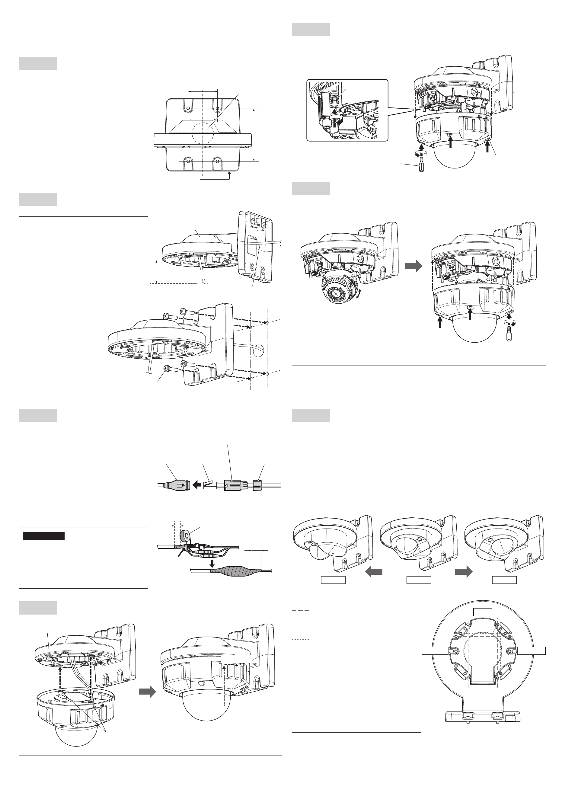
Step 2
Decide the location where this product is to be attached on the wall, then
make the holes for fixing and wiring as shown in the below illustration.
* Determine the diameter and depth of the holes
according to the specifications of the fixing
screws (4 pcs.) (M4: procured separately).
NOTE
When wiring using the “wiring hole on the
side” of the camera, the “wiring hole” in the
illustration at right is not necessary.
Step 3
Thread the cables through this product, then fix to the wall.
NOTE
When installing outside, waterproof the
wiring hole and the holes for the fixing
screws.
Fixing screws (4 pcs.) (M4: locally procured)
Minimum pullout strength:
196 N {44 lbf} (per 1 pc.)
Wiring hole on the side
Wiring hole
ø30 mm
{1-3/16 inches}
46 mm
{1-13/16 inches}
83.5 mm
{3-9/32
inches}
This product
Cables
100 mm {3-15/16 inches}
Fixing screws
Step 6
Remove the camera enclosure (when installing a camera type
other than the indoor dome type), then tighten the camera fixing
screws (red) to fix the camera firmly.
Camera fixing
screw (red)
Enclosure fixing
screws (4 places)
Bit
(camera accessory)
Step 7
After adjusting the angular field of view of the camera, fix the
enclosure to the original poisition.
Refer to the Installation Guide for the camera for detailed
adjustment methods.
Recommended tightening torque
: 0.78 N·m {0.58 lbf·ft}
NOTE
The recommended tightening torque for the screws depends on the camera you are
using. Refer to the Installation Guide for each camera.
Step 4
Connect the cables to the camera.
*. The following waterproofing procedures are
not necessary for indoor installations. Connect
directly to the camera.
1 Connect the RJ45 network cable and the
Ethernet cable.
NOTE
Refer to the Installation Guide for the
camera for information on how to
assemble the waterproof connector.
2
If necessary, also connect and waterproof other
cables as shown in the illustration at right.
IMPORTANT
Stretch the tape by approx. twice and wind
it around the cable.
Start and finish winding the waterproof
tape so that it overlaps the external covers
of the cables by approximately 20 mm
{25/32 inches}.
Step 5
Attach the camera to this product and temporarily fix.
Approx. 15°
Holes of the attachment
plate (4 places)
Attachment mounting
screws (2 places)
NOTE
Refer to the Installation Guide for the camera for information on how to attach.
RJ45
waterproof
jack
RJ45 plug
(locally procured)
RJ45 waterproof
connector cover
(camera accessory)
RJ45 waterproof
connector cap
(camera accessory)
RJ45 Network cable Ethernet cable
Waterproof tape (camera accessory)
Approx. 20 mm {25/32 inches}
Approx. 20 mm
{25/32 inches}
Wind the tape in a
half-overlapping
manner.
Step 8
Attaching the compact dome type WV-S31xx, S35xx series
1 Process the installation surface according to the description in Step 2.
2 Referring to the description in Step 3, thread the network cable through this product (the
attachment plate is not attached) to fix it in place.
3 Either connect the RJ45 waterproof connector according to Step 4, or for the indoor model,
attach the network cable directly to the camera.
4 Fix the camera to this product. The camera can be attached in the forward facing direction or
rotated at ±90° to the left or right. When shooting close to the wall, change the fixing position
by ±90° in either direction.
Refer to the Installation Guide for the camera for detailed attachment methods.
The following illustration shows an example of installing an indoor compact dome type
WV-S31xx series.
Left 90° Right 90°Front
<Positions for holes used for attachment>
Fixing positions for screws when using
an outdoor compact dome type
WV-S35xx series
(Front, rotated 90° left, rotated 90° right)
Fixing positions for screws when using
an indoor compact dome type
WV-S31xx series
(Front, rotated 90° left, rotated 90° right)
Recommended tightening torque
: 0.78 N·m {0.58 lbf·ft}
NOTE
When fixing a compact dome type
camera, of the three fixing positions, use
the 2 forward places to fix.
Right 90°Left 90°
Front
WV-QWL500_PGQX2359YAC6_カメラ壁取付金具_en.indd 2 2021/10/28 15:41:17