
Network Video Recorder
User Manual

About this Document
● This Document includes instructions for using and managing the Product. Pictures,
charts, images and all other information hereinafter are for description and
explanation only.
● The information contained in the Document is subject to change, without notice,
due to firmware updates or other reasons. Please find the latest version of the
Document at the Hikvision website (
https://www.hikvision.com). Unless
otherwise agreed, Hangzhou Hikvision Digital Technology Co., Ltd. or its affiliates
(hereinafter referred to as "Hikvision") makes no warranties, express or implied.
● Please use the Document with the guidance and assistance of professionals
trained in supporting the Product.
About this Product
● This product can only enjoy the after-sales service support in the country or region
where the purchase is made.
● If the product you choose is a video product, please scan the following QR code to
obtain the "Initiatives on the Use of Video Products", and read it carefully.
Acknowledgment of Intellectual Property Rights
● Hikvision owns the copyrights and/or patents related to the technology embodied
in the Products described in this Document, which may include licenses obtained
from third parties.
● Any part of the Document, including text, pictures, graphics, etc., belongs to
Hikvision. No part of this Document may be excerpted, copied, translated, or
modified in whole or in part by any means without written permission.
● and other Hikvision’s trademarks and logos are the properties
of Hikvision in various jurisdictions.
● Other trademarks and logos mentioned are the properties of their respective
owners.
● The terms HDMI and HDMI High-Definition Multimedia Interface, and
the HDMI Logo are trademarks or registered trademarks of HDMI Licensing
Administrator, Inc. in the United States and other countries.
LEGAL DISCLAIMER
● TO THE MAXIMUM EXTENT PERMITTED BY APPLICABLE LAW, THIS DOCUMENT
AND THE PRODUCT DESCRIBED, WITH ITS HARDWARE, SOFTWARE AND
FIRMWARE, ARE PROVIDED "AS IS" AND "WITH ALL FAULTS AND ERRORS".
HIKVISION MAKES NO WARRANTIES, EXPRESS OR IMPLIED, INCLUDING WITHOUT

LIMITATION, MERCHANTABILITY, SATISFACTORY QUALITY, OR FITNESS FOR A
PARTICULAR PURPOSE. THE USE OF THE PRODUCT BY YOU IS AT YOUR OWN RISK.
IN NO EVENT WILL HIKVISION BE LIABLE TO YOU FOR ANY SPECIAL,
CONSEQUENTIAL, INCIDENTAL, OR INDIRECT DAMAGES, INCLUDING, AMONG
OTHERS, DAMAGES FOR LOSS OF BUSINESS PROFITS, BUSINESS INTERRUPTION, OR
LOSS OF DATA, CORRUPTION OF SYSTEMS, OR LOSS OF DOCUMENTATION,
WHETHER BASED ON BREACH OF CONTRACT, TORT (INCLUDING NEGLIGENCE),
PRODUCT LIABILITY, OR OTHERWISE, IN CONNECTION WITH THE USE OF THE
PRODUCT, EVEN IF HIKVISION HAS BEEN ADVISED OF THE POSSIBILITY OF SUCH
DAMAGES OR LOSS.
● YOU ACKNOWLEDGE THAT THE NATURE OF THE INTERNET PROVIDES FOR
INHERENT SECURITY RISKS, AND HIKVISION SHALL NOT TAKE ANY
RESPONSIBILITIES FOR ABNORMAL OPERATION, PRIVACY LEAKAGE OR OTHER
DAMAGES RESULTING FROM CYBER-ATTACK, HACKER ATTACK, VIRUS INFECTION,
OR OTHER INTERNET SECURITY RISKS; HOWEVER, HIKVISION WILL PROVIDE
TIMELY TECHNICAL SUPPORT IF REQUIRED.
● YOU AGREE TO USE THIS PRODUCT IN COMPLIANCE WITH ALL APPLICABLE LAWS,
AND YOU ARE SOLELY RESPONSIBLE FOR ENSURING THAT YOUR USE CONFORMS
TO THE APPLICABLE LAW. ESPECIALLY, YOU ARE RESPONSIBLE, FOR USING THIS
PRODUCT IN A MANNER THAT DOES NOT INFRINGE ON THE RIGHTS OF THIRD
PARTIES, INCLUDING WITHOUT LIMITATION, RIGHTS OF PUBLICITY, INTELLECTUAL
PROPERTY RIGHTS, OR DATA PROTECTION AND OTHER PRIVACY RIGHTS. YOU
SHALL NOT USE THIS PRODUCT FOR ANY PROHIBITED END-USES, INCLUDING THE
DEVELOPMENT OR PRODUCTION OF WEAPONS OF MASS DESTRUCTION, THE
DEVELOPMENT OR PRODUCTION OF CHEMICAL OR BIOLOGICAL WEAPONS, ANY
ACTIVITIES IN THE CONTEXT RELATED TO ANY NUCLEAR EXPLOSIVE OR UNSAFE
NUCLEAR FUEL-CYCLE, OR IN SUPPORT OF HUMAN RIGHTS ABUSES.
● IN THE EVENT OF ANY CONFLICTS BETWEEN THIS DOCUMENT AND THE
APPLICABLE LAW, THE LATTER PREVAILS.
© Hangzhou Hikvision Digital Technology Co., Ltd. All rights reserved.

Network Video Recorder User Manual
3
Regulatory Information
FCC Information
Please take attention that changes or modification not expressly approved by the party
responsible for compliance could void the user’s authority to operate the equipment.
FCC compliance: This equipment has been tested and found to comply with the limits for a Class
A digital device, pursuant to part 15 of the FCC Rules. These limits are designed to provide
reasonable protection against harmful interference when the equipment is operated in a
commercial environment. This equipment generates, uses, and can radiate radio frequency
energy and, if not installed and used in accordance with the instruction manual, may cause
harmful interference to radio communications. Operation of this equipment in a residential area
is likely to cause harmful interference in which case the user will be required to correct the
interference at his own expense.
FCC Conditions
This device complies with part 15 of the FCC Rules. Operation is subject to the following two
conditions:
1. This device may not cause harmful interference.
2. This device must accept any interference received, including interference that may cause
undesired operation.
EU Conformity Statement
This product and - if applicable - the supplied accessories too are marked with "CE" and
comply therefore with the applicable harmonized European standards listed under the
EMC Directive 2014/30/EU, the LVD Directive 2014/35/EU, the RoHS Directive 2011/65/EU.
2012/19/EU (WEEE directive): Products marked with this symbol cannot be disposed of
as unsorted municipal waste in the European Union. For proper recycling, return this
product to your local supplier upon the purchase of equivalent new equipment, or
dispose of it at designated collection points. For more information see:
www.recyclethis.info
2006/66/EC (battery directive): This product contains a battery that cannot be disposed
of as unsorted municipal waste in the European Union. See the product documentation
for specific battery information. The battery is marked with this symbol, which may
include lettering to indicate cadmium (Cd), lead (Pb), or mercury (Hg). For proper recycling,
return the battery to your supplier or to a designated collection point. For more information see:
www.recyclethis.info
Industry Canada ICES-003 Compliance
This device meets the CAN ICES-3 (A)/NMB-3(A) standards requirements.
Network Video Recorder User Manual
4
Applicable Models
This manual is applicable to the models listed in the following table.
Series
Model
DS-96000NI-I16
DS-96064NI-I16
DS-96128NI-I16
DS-96256NI-I16
DS-96000NI-I16/H
DS-96128NI-I16/H
DS-96256NI-I16/H
DS-96000NI-I24
DS-96128NI-I24
DS-96256NI-I24
DS-96000NI-I24/H
DS-96128NI-I24/H
DS-96256NI-I24/H
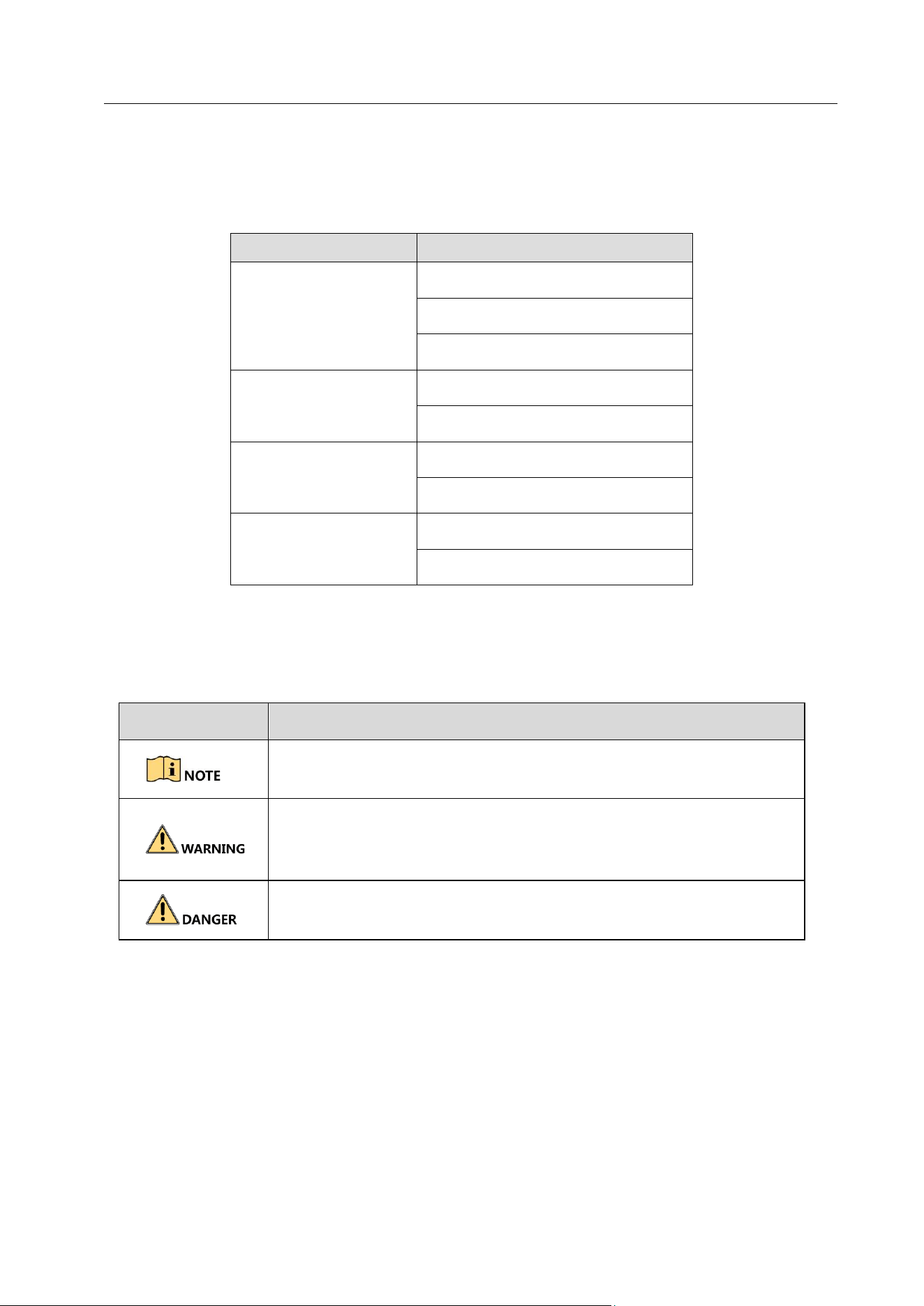
Symbol Conventions
The symbols that may be found in this document are defined as follows.
Symbol
Description
Provides additional information to emphasize or supplement
important points of the main text.
Indicates a potentially hazardous situation, which if not avoided,
could result in equipment damage, data loss, performance
degradation, or unexpected results.
Indicates a hazard with a high level of risk, which if not avoided,
will result in death or serious injury.

Network Video Recorder User Manual
5
Safety Instructions
Proper configuration of all passwords and other security settings is the responsibility of the
installer and/or end-user.
In the use of the product, you must be in strict compliance with the electrical safety
regulations of the nation and region. Please refer to technical specifications for detailed
information.
Input voltage should meet both the SELV (Safety Extra Low Voltage) and the Limited Power
Source with 100~240 VAC or 12 VDC according to the IEC60950-1 standard. Please refer to
technical specifications for detailed information.
Do not connect several devices to one power adapter as adapter overload may cause over-
heating or a fire hazard.
Please make sure that the plug is firmly connected to the power socket.
If smoke, odor or noise rise from the device, turn off the power at once and unplug the power
cable, and then please contact the service center.
Preventive and Cautionary Tips
Before connecting and operating your device, please be advised of the following tips:
Ensure unit is installed in a well-ventilated, dust-free environment.
Unit is designed for indoor use only.
Keep all liquids away from the device.
Ensure environmental conditions meet factory specifications.
Ensure unit is properly secured to a rack or shelf. Major shocks or jolts to the unit as a result of
dropping it may cause damage to the sensitive electronics within the unit.
Use the device in conjunction with an UPS if possible.
Power down the unit before connecting and disconnecting accessories and peripherals.
A factory recommended HDD should be used for this device.
Improper use or replacement of the battery may result in hazard of explosion. Replace with
the same or equivalent type only. Dispose of used batteries according to the instructions
provided by the battery manufacturer.

Network Video Recorder User Manual
6
When installing the device into a cabinet over 2U height, it is suggested to use rack shelf to
bear the weight. If the cabinet height is over 4U, it is suggested to use slide rails or rack shelf
to bear the weight.

Network Video Recorder User Manual
7
Product Key Features
General
Connectable to network cameras, network dome and encoders.
Connectable to the third-party network cameras like ACTI, Arecont, AXIS, Bosch, Brickcom,
Canon, PANASONIC, Pelco, SAMSUNG, SANYO, SONY, Vivotek and ZAVIO, and cameras that
adopt ONVIF or PSIA protocol.
Connectable to the smart IP cameras.
H.265, H.265+, H.264, H.264+, SVAC, MPEG4, and MJPEG (only for Hikvision IP camera) video
formats.
PAL/NTSC adaptive video inputs.
Each channel supports dual-stream.
Up to 128/256 network cameras can be added according to different models.
Independent configuration for each channel, including resolution, frame rate, bit rate, image
quality, etc.
The quality of the input and output record is configurable.
Local Monitoring
HDMI 1, HDMI 2, and VGA outputs are provided.
HDMI 2 video output at up to 4K resolution.
Multiple screen display in live view is supported, and the display sequence of channels is
adjustable.
Live view screen can be switched in group. Manual switch and auto-switch are provided and
the auto-switch interval is configurable.
Configurable main stream and sub-stream for the live view.
Quick setting menu is provided for live view.
Motion detection, video tampering, video exception alert and video loss alert functions.
Privacy mask.
Multiple PTZ protocols supported; PTZ preset, patrol and pattern.
Zooming in by clicking the mouse and PTZ tracing by dragging mouse.
HDD Management
Up to 16 SATA hard disks and 1 eSATA disk can be connected for DS-96000NI-I16(/H) series
NVR.
Up to 24 SATA hard disks and 1 eSATA disk can be connected for DS-96000NI-I24(/H) series
NVR.
Up to 10 TB storage capacity for each disk supported.
Supports 8 network disks (NAS/IP SAN disk).

Network Video Recorder User Manual
8
Supports S.M.A.R.T. and bad sector detection.
HDD group management.
Supports HDD standby function.
HDD property: redundancy, read-only, read/write (R/W).
HDD quota management; different capacity can be assigned to different channel.
RAID 0, RAID 1, RAID 5, RAID 6, and RAID 10 are supported.
Hot-swappable RAID storage scheme, and can be enabled and disabled on your demand. And
16/24 arrays can be configured.
Disk clone to the eSATA disk.
HDD health monitoring.
Recording, Capture and Playback
Holiday recording schedule configuration.
Continuous and event video recording parameters.
Multiple recording types: manual, continuous, alarm, motion, motion | alarm, motion &
alarm, and VCA.
8 recording time periods with separated recording types.
Pre-record and post-record for alarm, motion detection for recording, and pre-record time for
schedule and manual recording.
Searching record files and captured pictures by events (alarm input/motion detection).
Tag adding for record files, searching and playing back by tags.
Locking and unlocking record files.
Local redundant recording and capture.
Normal/Smart/custom video playback mode.
Searching and playing back record files by channel number, recording type, start time, end
time, etc.
Supports the playback by main stream or sub-stream.
Smart search for the selected area in the video.
Zooming in when playback.
Reverse playback of multi-channel.
Supports pause, play reverse, speed up, speed down, skip forward, and skip backward when
playback, and locating by dragging the mouse.
Supports thumbnails view and fast view during playback.
Up to 16-ch synchronous playback at 1080p real time.
Supports playback by transcoded stream.
Manual capture, continuous capture of video images and playback of captured pictures.
Supports enabling H.264+ to ensure high video quality with lowered bitrate.

Network Video Recorder User Manual
9
Files Management
Important files search and export.
Vehicle detection files and human appearance files search and export.
Export video data by USB, SATA or eSATA device.
Export video clips when playback.
Management and maintenance of backup devices.
Either Normal or Hot Spare working mode is configurable to constitute an N+1 hot spare
system.
Alarm and Exception
Configurable arming time of alarm input/output.
Alarm for video loss, motion detection, tampering, abnormal signal, video input/output
standard mismatch, illegal login, network disconnected, IP confliction, abnormal
record/capture, HDD error, and HDD full, etc.
VCA detection alarm is supported.
Smart analysis for people counting and heat map
Alarm triggers full screen monitoring, audio alarm, sending email, alarm output, etc.
Automatic restore when system is abnormal.
Other Local Functions
Operable by front panel, mouse, remote control, or control keyboard.
Three-level user management; admin user is allowed to create many operating accounts and
define their operating permission, which includes the limit to access any channel.
Admin password resetting by exporting/importing the GUID file.
Operation, alarm, exceptions and log recording and searching.
Manually triggering and clearing alarms.
Import and export of device configuration information.
Network Functions
Four self-adaptive 10M/100M/1000M network interfaces and the multi-address, and network
fault-tolerance working modes are configurable.
IPv6 is supported.
TCP/IP protocol, DHCP, DNS, DDNS, NTP, SADP, SMTP, NFS, and iSCSI are supported.
TCP, UDP and RTP for unicast.
Auto/Manual port mapping by UPnP
TM
.
Support access by Hik-Connect.
Remote web browser access by HTTPS ensures high security.

Network Video Recorder User Manual
10
ANR (Automatic Network Replenishment) function is supported, which enables the IP camera
save the recording files in the local storage when the network is disconnected, and
synchronizes the files to the device when the network is resumed.
Remote reverse playback via RTSP.
Supports accessing by the platform via ONVIF.
Remote search, playback, download, locking and unlocking of the record files, and support
downloading files broken transfer resume.
Remote parameters setup; remote import/export of device parameters.
Remote viewing of the device status, system logs and alarm status.
Remote keyboard operation.
Remote HDD formatting and program upgrading.
Remote system restart and shutdown.
RS-232, RS-485 transparent channel transmission.
Alarm and exception information can be sent to the remote host
Remotely start/stop recording.
Remotely start/stop alarm output.
Remote PTZ control.
Two-way audio and voice broadcasting.
Embedded WEB server.
Development Scalability:
SDK for Windows system.
Source code of application software for demo.
Development support and training for application system.

Network Video Recorder User Manual
11
TABLE OF CONTENTS
Chapter 1 Introduction .............................................................................................................. 18
Front Panel .................................................................................................................. 18
DS-96000NI-I16(/H) Series .................................................................................. 18
DS-96000NI-I24(/H) Series .................................................................................. 19
IR Remote Control Operations ..................................................................................... 20
Pairing (Enabling) the IR Remote to a Specific Device (optional) .......................... 20
Unpairing (Disabling) an IR Remote from a Device............................................... 21
Troubleshooting .................................................................................................. 24
USB Mouse Operation.................................................................................................. 25
Rear Panel.................................................................................................................... 26
Chapter 2 Getting Started .......................................................................................................... 28
Start up the Device ...................................................................................................... 28
Activate the Device ...................................................................................................... 28
Configure Unlock Pattern for Login .............................................................................. 29
Log in to the Device ..................................................................................................... 30
Log in via Unlock Pattern ..................................................................................... 30
Log in via Password ............................................................................................. 31
Enter Wizard to Configure Quick Basic Settings ............................................................ 32
Enter Main Menu ......................................................................................................... 36
System Operation ........................................................................................................ 37
Log out ................................................................................................................ 37
Shut Down the Device ......................................................................................... 37
Reboot the Device ............................................................................................... 37
Chapter 3 Camera Management ............................................................................................... 38
Add the IP Cameras...................................................................................................... 38
Add the IP Camera Manually ............................................................................... 38
Add the Automatically Searched Online IP Cameras ............................................ 39
Enable the H.265 Stream Access .................................................................................. 40
Upgrade the IP Camera ................................................................................................ 40
Configure the Customized Protocols ............................................................................ 40
Chapter 4 Camera Settings ........................................................................................................ 42
Configure OSD Settings ................................................................................................ 42

Network Video Recorder User Manual
12
Configure Privacy Mask ................................................................................................ 43
Configure the Video Parameters .................................................................................. 44
Configure the Day/Night Switch ................................................................................... 44
Configure IP Camera Time Sync ................................................................................... 44
Configure Other Camera Parameters ........................................................................... 45
Chapter 5 Live View .................................................................................................................. 46
Start Live View ............................................................................................................. 46
Digital Zoom ........................................................................................................ 46
Fisheye View ....................................................................................................... 46
3D Positioning ..................................................................................................... 47
Live View Strategy ............................................................................................... 47
Target Tracking .................................................................................................... 48
Switch Main/Auxiliary Port .................................................................................. 48
Target Detection .......................................................................................................... 48
Configure Live View Settings ........................................................................................ 49
Configure Live View Layout .......................................................................................... 50
Configure Custom Live View Layout ..................................................................... 50
Configure Live View Mode................................................................................... 51
Configure Auto-Switch of Cameras ............................................................................... 52
Configure Channel-zero Encoding ................................................................................ 52
Using an Auxiliary Monitor ........................................................................................... 53
Chapter 6 PTZ Control .............................................................................................................. 54
PTZ Control Wizard ...................................................................................................... 54
ConfigurePTZ Parameters ............................................................................................. 54
Set PTZ Presets, Patrols & Patterns............................................................................... 55
Set a Preset ......................................................................................................... 55
Call a Preset ........................................................................................................ 56
Set a Patrol .......................................................................................................... 57
Call a Patrol ......................................................................................................... 58
Set a Pattern ....................................................................................................... 59
Call a Pattern ....................................................................................................... 60
Set Linear Scan Limits .......................................................................................... 60
Call Linear Scan ................................................................................................... 61
One-touch Park ................................................................................................... 61
Auxiliary Functions ....................................................................................................... 62

Network Video Recorder User Manual
13
Chapter 7 Storage ....................................................................................................................... 64
Storage Device Management ....................................................................................... 64
Install the HDD .................................................................................................... 64
Add the Network Disk ......................................................................................... 64
Configure eSATA for Data Storage ........................................................................ 66
Configure eSATA for Auto Backup ........................................................................ 67
Storage Mode .............................................................................................................. 68
Configure HDD Group .......................................................................................... 68
Configure HDD Quota .......................................................................................... 70
Configure Data Release ....................................................................................... 71
Recording Parameters .................................................................................................. 72
Main Stream ....................................................................................................... 72
Sub-Stream ......................................................................................................... 73
Picture ................................................................................................................ 73
ANR ..................................................................................................................... 73
Configure Advanced Recording Settings .............................................................. 73
Configure Recording Schedule ..................................................................................... 74
Configure Continuous Recording .................................................................................. 76
Configure Motion Detection Triggered Recording ........................................................ 76
Configure Event Triggered Recording ........................................................................... 76
Configure Alarm Triggered Recording ........................................................................... 77
Configure Picture Capture ............................................................................................ 77
Configure Holiday Recording and Capture .................................................................. 78
Configure Redundant Recording and Capture............................................................. 80
Chapter 8 Disk Array ................................................................................................................. 82
Create Disk Array ......................................................................................................... 82
Enable RAID ........................................................................................................ 82
One-Touch Creation ............................................................................................ 83
Manual Creation ................................................................................................. 83
Rebuild Array ............................................................................................................... 85
Configure Hot Spare Disk ..................................................................................... 85
Automatically Rebuild Array ................................................................................ 85
Manually Rebuild Array ....................................................................................... 86
Delete Array ................................................................................................................. 87
Check and Edit Firmware ............................................................................................. 88

Network Video Recorder User Manual
14
Chapter 9 File Management ...................................................................................................... 89
Search and Export All Files ........................................................................................... 89
Search Files ......................................................................................................... 89
Export Files ......................................................................................................... 89
Search and Export Human Files .................................................................................... 90
Search Human Files ............................................................................................. 90
Export Human Files ............................................................................................. 90
Search and Export Vehicle Files .................................................................................... 91
Search Vehicle Files ............................................................................................. 91
Export Vehicle Files ............................................................................................. 91
Search History Operation ............................................................................................. 92
Save Search Condition ......................................................................................... 92
Call Search History .............................................................................................. 92
Chapter 10 Playback .................................................................................................................. 93
Play Video Files .......................................................................................................... 93
Instant Playback ................................................................................................ 93
Play Normal Video ............................................................................................. 93
Play Smart Searched Video ................................................................................ 94
Play Custom Searched Files ............................................................................... 95
Video Synopsis .................................................................................................. 96
Play Tag Files ..................................................................................................... 97
Play Event Files .................................................................................................. 99
Play by Sub-periods ......................................................................................... 100
Play Log Files ................................................................................................... 101
Play External File ........................................................................................... 101
Playback Operations ................................................................................................ 102
Set Play Strategy in Smart/Custom Mode ........................................................ 102
Edit Video Clips ............................................................................................... 103
Switch between Main Stream and Sub-Stream ................................................ 103
Thumbnails View ............................................................................................. 103
Fisheye View ................................................................................................... 103
Fast View ......................................................................................................... 104
Digital Zoom .................................................................................................... 104
Chapter 11 Event and Alarm Settings .................................................................................... 105
Configure Arming Schedule ...................................................................................... 105

Network Video Recorder User Manual
15
Configure Alarm Linkage Actions .............................................................................. 105
The alarm signal will be transmitted automatically at detection mode when remote
alarm host is configured. Please refer to Chapter 14.8 Configuring NAT ........................... 107
Configure Motion Detection Alarm .......................................................................... 109
Configure Video Loss Alarm ..................................................................................... 111
Configure Video Tampering Alarm............................................................................ 112
Configure Sensor Alarms .......................................................................................... 113
Configure Alarm Input ..................................................................................... 113
Configure One-Key Disarming .......................................................................... 114
Configure Alarm Output .................................................................................. 114
Configure Exceptions Alarm ..................................................................................... 116
Alarm Linkage Actions .............................................................................................. 117
Configure Auto-switch Full Screen Monitoring ................................................ 117
Configure Audio Warning ................................................................................ 118
Notify Surveillance Center ............................................................................... 118
Configure Email Linkage .................................................................................. 118
Trigger Alarm Output ...................................................................................... 119
Configure PTZ Linkage ..................................................................................... 119
Trigger or Clear Alarm Output Manually ................................................................. 120
Chapter 12 VCA Event Alarm ................................................................................................. 121
Face Detection ......................................................................................................... 121
Vehicle Detection ..................................................................................................... 122
Line Crossing Detection ............................................................................................ 123
Intrusion Detection .................................................................................................. 124
Region Entrance Detection ....................................................................................... 126
Region Exiting Detection .......................................................................................... 127
Unattended Baggage Detection ............................................................................... 128
Object Removal Detection ....................................................................................... 129
Audio Exception Detection ....................................................................................... 130
Sudden Scene Change Detection ............................................................................ 132
Defocus Detection.................................................................................................. 133
PIR Alarm ............................................................................................................... 133
Thermal Camera Detection .................................................................................... 134
Queue Management ............................................................................................. 135
Chapter 13 Smart Analysis ...................................................................................................... 137

Network Video Recorder User Manual
16
People Counting....................................................................................................... 137
Heat Map ................................................................................................................. 137
Chapter 14 Network Settings .................................................................................................. 139
Configure TCP/IP Settings ......................................................................................... 139
Configure Hik-Connect ............................................................................................. 140
Configure DDNS ....................................................................................................... 141
Configure PPPoE ...................................................................................................... 142
Configure NTP .......................................................................................................... 142
Configure SNMP ....................................................................................................... 143
Configure Email........................................................................................................ 144
Configuring NAT ....................................................................................................... 145
Configure Ports ........................................................................................................ 146
Chapter 15 Hot Spare Device Backup .................................................................................... 148
Set Hot Spare Device ................................................................................................ 148
Set Working Device .................................................................................................. 149
Manage Hot Spare System ....................................................................................... 149
Chapter 16 System Maintenance ............................................................................................. 151
Storage Device Maintenance .................................................................................... 151
Configure Disk Clone ....................................................................................... 151
S.M.A.R.T Detection ........................................................................................ 152
Bad Sector Detection ....................................................................................... 153
HDD Health Detection ..................................................................................... 154
Search & Export Log Files ......................................................................................... 155
Search the Log Files ......................................................................................... 155
Export the Log Files ......................................................................................... 156
Import/Export IP Camera Configuration Files ........................................................... 157
Import/Export Device Configuration Files................................................................. 159
Upgrade System ....................................................................................................... 160
Upgrade by Local Backup Device ..................................................................... 160
Upgrade by FTP ............................................................................................... 160
Upgrade by Hik-Connect .................................................................................. 161
Restore Default Settings ........................................................................................... 162
System Service ......................................................................................................... 162
Network Security Settings ............................................................................... 162
Managing ONVIF User Accounts ...................................................................... 164

Network Video Recorder User Manual
17
Managing IP Camera Activation ....................................................................... 165
Configure Stream Encryption ................................................................................... 166
Chapter 17 General System Settings ....................................................................................... 168
Configure General Settings ....................................................................................... 168
Configure Date & Time ............................................................................................. 169
Configure DST Settings ............................................................................................. 170
Manage User Accounts ............................................................................................ 170
Add a User ...................................................................................................... 170
Set the Permission for a User .......................................................................... 172
Set Local Live View Permission for Non-Admin Users....................................... 174
Set Live View Permission on Lock Screen ......................................................... 175
Edit the Admin User ........................................................................................ 176
Edit the Operator/Guest User .......................................................................... 178
Delete a User .................................................................................................. 178
Configure Password Security .................................................................................... 179
Export GUID File .............................................................................................. 179
Configure Security Questions .......................................................................... 179
Configure Reserved Email ................................................................................ 180
Reset Password ........................................................................................................ 181
Reset Password by GUID ................................................................................. 181
Reset Password by Security Questions............................................................. 181
Reset Password by Reserved Email .................................................................. 182
Chapter 18 Appendix ............................................................................................................... 183
Glossary ................................................................................................................... 183
Troubleshooting ....................................................................................................... 184
Network Video Recorder User Manual
18
Chapter 1 Introduction
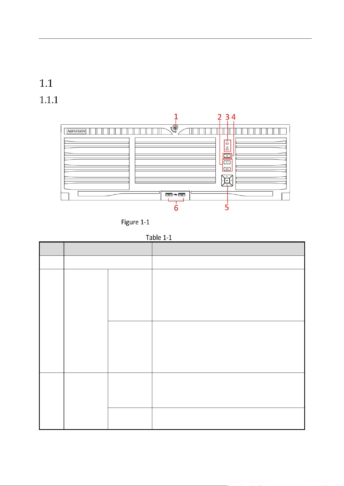
Front Panel
DS-96000NI-I16(/H) Series
DS-96000NI-I16(/H) Series
Description
No.
Name
Description
1
Panel lock
Locks or unlocks the panel by the key.
2
Shortcut
buttons
Exit
Returns to the previous menu.
Press it twice quickly to switch the main and
auxiliary port.
In live view mode, press it to enter PTZ control
interface.
Menu
Press it to pop up main menu.
Hold it for 5 seconds to turn on/off button
sound.
During playback, press it to show/hide control
panel.
3
Status
indicator
HDD
Solid red: at least one HDD is installed
Unlit: no HDD is detected.
Flashing red: HDD is reading/writing.
Tx/Rx
Flashing blue indicates network communication is
normal.
Network Video Recorder User Manual
19
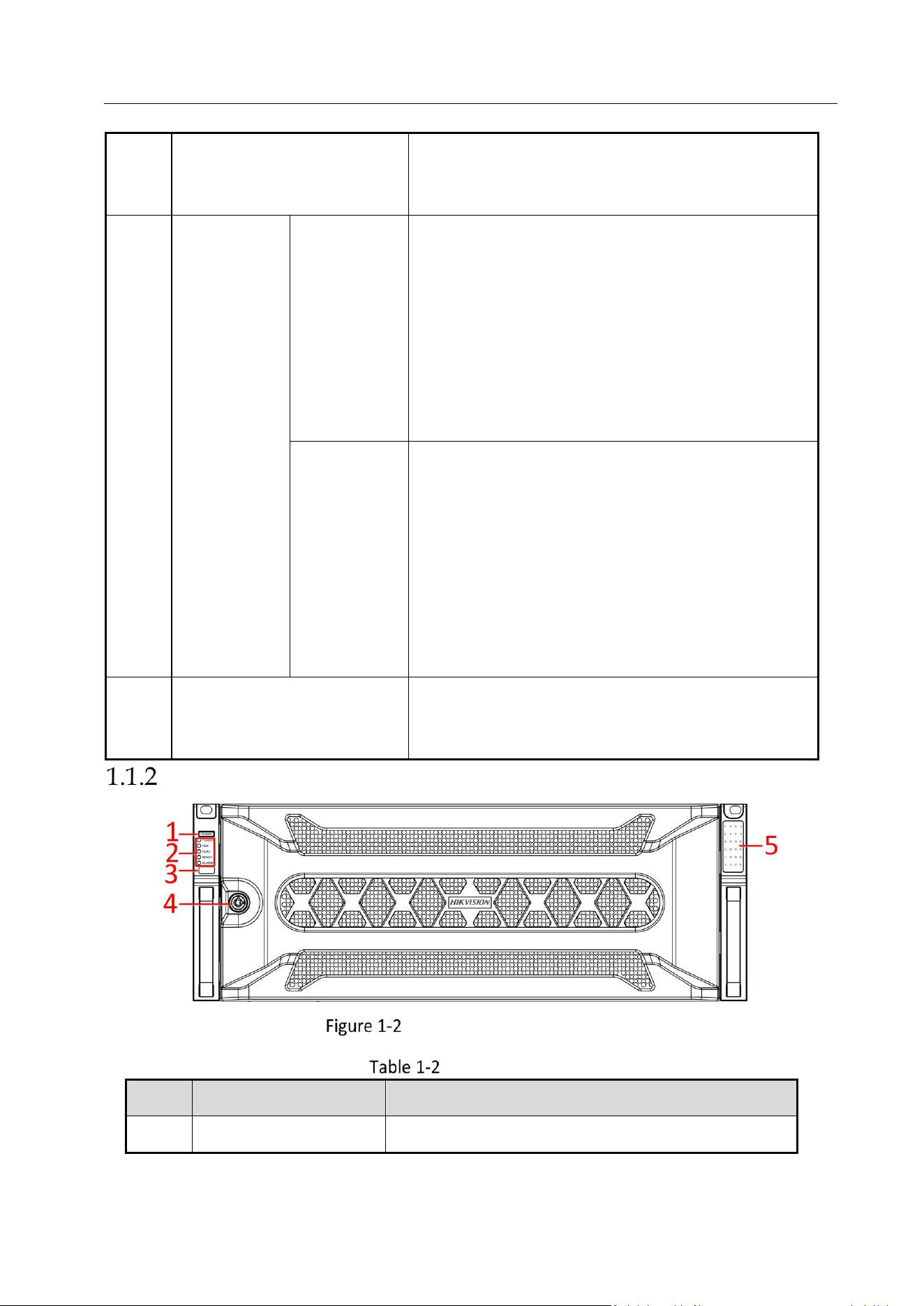
DS-96000NI-I24(/H) Series
DS-96000NI-I24(/H) Series
Panel Description
4
Power switch
Powers on/off device. Solid blue indicates device
is powered on. Solid red indicates device is shut
down.
5
Control
buttons
ENTER
Confirms selection in any of the menu modes.
Checks the checkbox fields.
Switches on/off status.
Plays or pauses the video playing in playback
mode.
Advances the video by a single frame in single-
frame playback mode.
Stops/starts auto switch in auto-switch mode.
DIRECTION
Navigates between different fields and items in
menus.
In the playback mode, use the Up and Down
buttons to speed up and slow down recorded
video. Use the Left and Right buttons to select
the next and previous video files.
Cycles through channels in live view mode.
Controls the movement of the PTZ camera in
PTZ control mode.
6
USB interfaces
Universal Serial Bus (USB) ports for additional
devices such as USB mouse and USB Hard Disk
Drive (HDD).
No.
Name
Description
1
Power switch
Powers on/off device.

Network Video Recorder User Manual
20
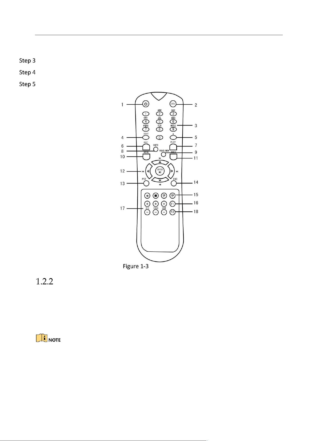
IR Remote Control Operations
The device may also be controlled with the included IR remote control, shown in Figure 1-3.
Batteries (2×AAA) must be installed before operation.
The IR remote is set at the factory to control the device (using default Device ID# 255) without
any additional steps. Device ID# 255 is the default universal device identification number shared
by the devices. You may also pair an IR Remote to a specific device by changing the Device ID#,
as follows:
Pairing (Enabling) the IR Remote to a Specific Device
(optional)
You can pair an IR Remote to a specific device by creating a user-defined Device ID#. This feature
is useful when using multiple IR Remotes and devices.
On the device:
Go to System > General.
Type a number (255 digits maximum) into the Device No. field.
2
Status
indicator
Power
Solid blue indicates device is powered on. Solid
red indicates device is shut down.
HDD
Solid red: at least one HDD is installed
Unlit: no HDD is detected.
Flashing red: HDD is reading/writing.
Tx/Rx
Flashing blue indicates network communication is
normal.
Ready
Solid blue indicates device runs properly.
Alarm
Solid red indicates alarm occurs.
3
USB interface
Universal Serial Bus (USB) ports for additional
devices such as USB mouse and USB Hard Disk
Drive (HDD).
4
Panel lock
Locks or unlocks the panel by the key.
5
HDD sequence
indicator
Shows the HDD installation slot.
Network Video Recorder User Manual
21
On the IR Remote:
Press the DEV button.
Use the Number buttons to enter the Device ID# that was entered into the device.
Press Enter button to accept the new Device ID#.
Remote Control
Unpairing (Disabling) an IR Remote from a Device
To unpair an IR Remote from a device so that the unit cannot control any device functions,
proceed as follows:
Press the DEV key on the IR Remote. Any existing Device ID# will be erased from the unit’s
memory and it will no longer function with the device.
(Re)-enabling the IR Remote requires pairing to a device. See “Pairing the IR Remote to a Specific
device (optional),” above.
The keys on the remote control closely resemble the ones on the front panel.

Network Video Recorder User Manual
22
IR Remote Functions
No.
Name
Function Description
1
POWER
ON/OFF
•To Turn Power On:
-If User Has Not Changed the Default device Device ID# (255):
1.Press Power On/Off button (1).
-If User Has Changed the device Device ID#:
1.Press DEV button.
2.Press Number buttons to enter user-defined Device ID#.
3.Press Enter button.
4.Press Power button to start device.
•To Turn device Off:
-If User Is Logged On:
1.Hold Power On/Off button (1) down for five seconds to display the
“Yes/No” verification prompt.
2.Use Up/Down Arrow buttons (12) to highlight desired selection.
3.Press Enter button (12) to accept selection.
-If User Is Not Logged On:
1.Hold Power On/Off button (1) down for five seconds to display the user
name/password prompt.
2.Press the Enter button (12) to display the on-screen keyboard.
3.Input the user name.
4.Press the Enter button (12) to accept input and dismiss the on-screen
keyboard.
5.Use the Down Arrow button (12) to move to the “Password” field.
6.Input password (use on-screen keyboard or numeric buttons (3) for
numbers).
7.Press the Enter button (12) to accept input and dismiss the on-screen
keyboard.
8.Press the OK button on the screen to accept input and display the
Yes/No” verification prompt (use Up/Down Arrow buttons (12) to move
between fields)
9.Press Enter button (12) to accept selection.

Network Video Recorder User Manual
23
User name/password prompt depends on device is configuration. See
“System Configuration” section.
2
DEV
Enable IR Remote: Press DEV button, enter device Device ID# with number
keys, press Enter to pair unit with the device
Disable IR Remote: Press DEV button to clear Device ID#; unit will no
longer be paired with the device
3
Numera
ls
Switch to the corresponding channel in Live View or PTZ Control mode
Input numbers in Edit mode
4
EDIT
Delete characters before cursor
Check the checkbox and select the ON/OFF switch
5
A
Adjust focus in the PTZ Control menu
Switch on-screen keyboards (upper and lower case alphabet, symbols, and
numerals)
6
REC
Enter Manual Record setting menu
Call a PTZ preset by using the numeric buttons in PTZ control settings
Turn audio on/off in Playback mode
7
PLAY
Go to Playback mode
Auto scan in the PTZ Control menu
8
INFO
Reserved
9
VOIP
Switches between main and spot output
Zooms out the image in PTZ control mode
10
MENU
Return to Main menu (after successful login)
N/A
Show/hide full screen in Playback mode
12
DIRECTI
ON
Navigate between fields and menu items
Use Up/Down buttons to speed up/slow down recorded video, and
Left/Right buttons to advance/rewind 30 secs in Playback mode
Cycle through channels in Live View mode
Control PTZ camera movement in PTZ control mode
ENTER
Confirm selection in any menu mode

Network Video Recorder User Manual
24
Troubleshooting
Make sure you have installed batteries properly in the remote control. And you have to aim the
remote control at the IR receiver in the front panel.
If there is no response after you press any button on the remote, follow the procedure below to
troubleshoot.
Go to System > General by operating the front control panel or the mouse.
Check and remember device ID#. The default ID# is 255. This ID# is valid for all the IR remote
controls.
Press the DEV button on the remote control.
Enter the device ID# you set in step 2.
Press the ENTER button on the remote.
Checks checkbox
Play or pause video in Playback mode
Advance video a single frame in single-frame Playback mode
Stop/start auto switch in auto-switch mode
13
PTZ
Enter PTZ Control mode
14
ESC
Go back to previous screen
N/A
15
RESERV
ED
Reserved
16
F1
Select all items on a list
N/A
Switch between play and reverse play in Playback mode
17
PTZ
Control
Adjust PTZ camera iris, focus, and zoom
18
F2
Cycle through tab pages
Switch between channels in Synchronous Playback mode

Network Video Recorder User Manual
25
If the Status indicator on the front panel turns blue, the remote control is operating properly. If
the Status indicator does not turn blue and there is still no response from the remote, please
check the following:
Batteries are installed correctly and the polarities of the batteries are not reversed.
Batteries are fresh and not out of charge.
IR receiver is not obstructed.
No fluorescent lamp is used nearby
If the remote still can’t function properly, please change a remote and try again, or contact the
device provider.
USB Mouse Operation
A regular 3-button (Left/Right/Scroll-wheel) USB mouse can also be used with this device. To use
a USB mouse:
Plug USB mouse into one of the USB interfaces on the front panel of the device.
The mouse should automatically be detected. If in a rare case that the mouse is not detected,
the possible reason may be that the two devices are not compatible, please refer to the
recommended the device list from your provider.
The operation of the mouse:
Description of the Mouse Control
Name
Action
Description
Left-Click
Single-Click
Live view: Select channel and show the quick set
menu.
Menu: Select and enter.
Double-
Click
Live view: Switch between single-screen and multi-
screen.
Click and
Drag
PTZ control: pan, tilt and zoom.
Video tampering, privacy mask and motion
detection: Select target area.
Digital zoom-in: Drag and select target area.
Live view: Drag channel/time bar.
Right-
Click
Single-Click
Live view: Show menu.
Menu: Exit current menu to upper level menu.
Scroll-
Wheel
Scrolling up
Live view: Previous screen.
Menu: Previous item.
Network Video Recorder User Manual
26
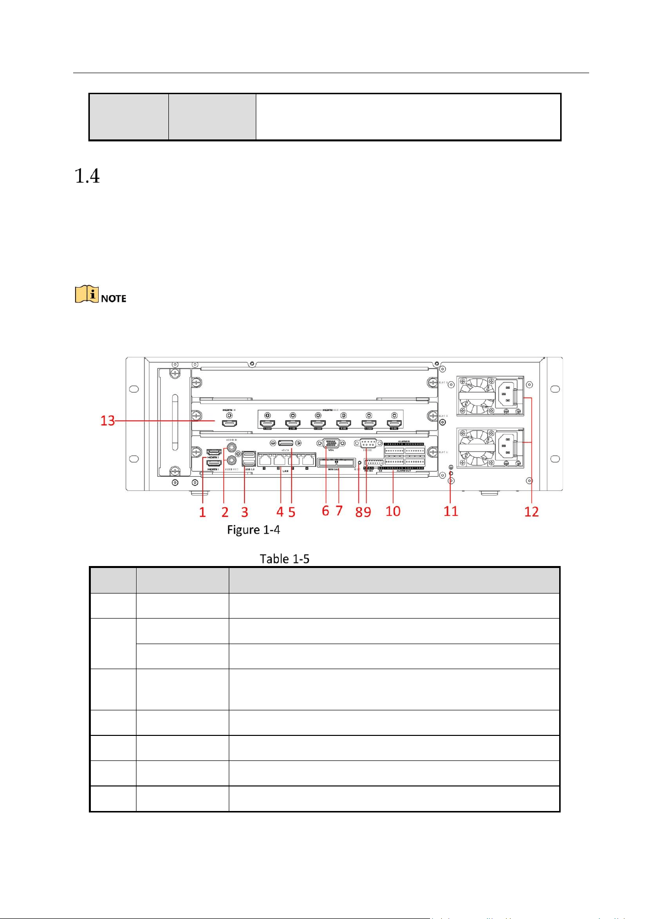
Rear Panel
Purpose:
The interfaces of DS-96000NI-I16 and DS-96000NI-I24 are the same. The interfaces of DS-
96000NI-I16/H and DS-96000NI-I24/H are the same. We take the example of DS-96000NI-I16/H
series to introduce the rear panel.
The difference between DS-96000NI-I16 and DS-96000NI-I16/H is DS-96000NI-I16/H contains the
decoding board, that is the module marked as 13 in following figure.
DS-96000NI-I16/H Series
Panel Description
Scrolling
down
Live view: Next screen.
Menu: Next item.
No.
Name
Description
1
HDMI 1/2
HDMI video output connector.
2
Audio in
RCA connector for audio input.
Audio out
RCA connector for audio output.
3
USB 3.0
Universal Serial Bus (USB 3.0) ports for additional devices
such as USB mouse and USB Hard Disk Drive (HDD).
4
LAN
4 10/100/1000 Mbps self-adaptive Ethernet interfaces.
5
eSATA
Connects external SATA HDD, CD/DVD-RM.
6
VGA
DB9 connector for VGA output.
7
Mini SAS
Connector for mini SAS.

Network Video Recorder User Manual
27
(optional)
8
Reset
Reset button.
9
RS-232
Connector for RS-232 devices.
10
Alarm in
Connector for alarm input.
Alarm out
Connector for alarm output.
RS-485
Connector for RS-485 devices.
KB
Connector for keyboard.
11
GND
Ground (needs to be connected when NVR starts up).
12
Power
supply
modules
Two power supply modules are used for redundancy.
13
Decoding
board
Decoding board. Only available for DS-96000NI-I16/H and
DS-96000NI-I24/H.
Network Video Recorder User Manual
28
Chapter 2 Getting Started
Start up the Device
Purpose:
Proper startup and shutdown procedures are crucial to expanding the life of the device.
Before you start:
Check that the voltage of the extra power supply is the same with the device’s requirement, and
the ground connection is working properly.
Connect the device power supply interface and electrical socket with delivered power cable. It
is HIGHLY recommended that an Uninterruptible Power Supply (UPS) be used in conjunction
with the device. The Power button on the front panel should be red, indicating the device is
receiving the power.
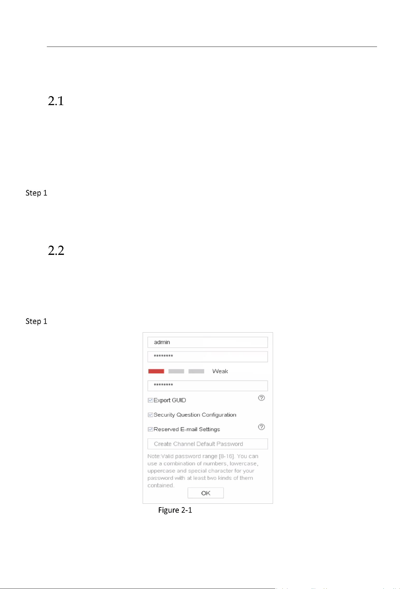
Activate the Device
Purpose:
For the first-time access, you need to activate the device by setting an admin password. No
operation is allowed before activation. You can also activate the device via Web Browser, SADP
or Client Software.
Enter the admin password twice.
Activate the Device
Network Video Recorder User Manual
29
We highly recommend you create a strong password of your own choosing (Using a minimum of 8
characters, including at least three of the following categories: upper case letters, lower case
letters, numbers, and special characters.) in order to increase the security of your product. And we
recommend you reset your password regularly, especially in the high security system, resetting the
password monthly or weekly can better protect your product.
Enter the password to activate the IP camera(s) connected to the device.
(Optional) Check Export GUID, Security Question Configuration, or Reserved E-mail
Click OK.
What to do next:
When you have enabled the Export GUID, continue to export the GUID file to the USB
flash driver for the future password resetting.
When you have enabled the Security Question Configuration, continue to set the security
questions for the future password resetting.
When you have enabled Reserved E-mail Settings, continue to set the reserved email for the
future password resetting.
After the device is activated, you should properly keep the password.
You can duplicate the password to the IP cameras that are connected with default protocol.
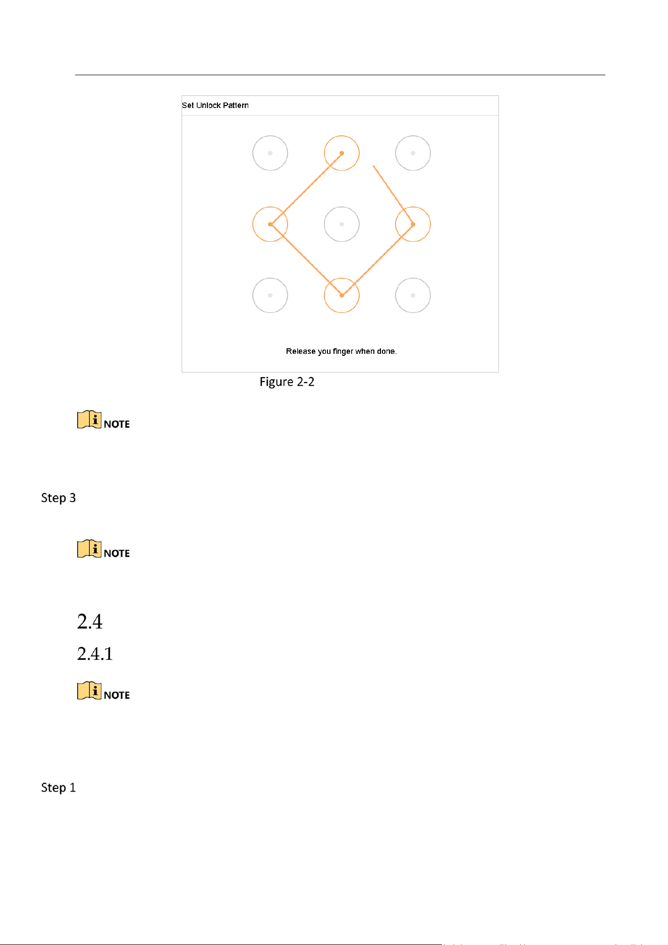
Configure Unlock Pattern for Login
For the admin user, you can configure the unlock pattern for device login.
After the device is activated, you can enter the following interface to configure the device
unlock pattern.
Use the mouse to draw a pattern among the 9 dots on the screen. Release the mouse when the
pattern is done.
Network Video Recorder User Manual
30
Draw the Pattern
Connect at least 4 dots to draw the pattern.
Each dot can be connected for once only.
Draw the same pattern again to confirm it. When the two patterns match, the pattern is
configured successfully.
If the two patterns are different, you must set the pattern again.
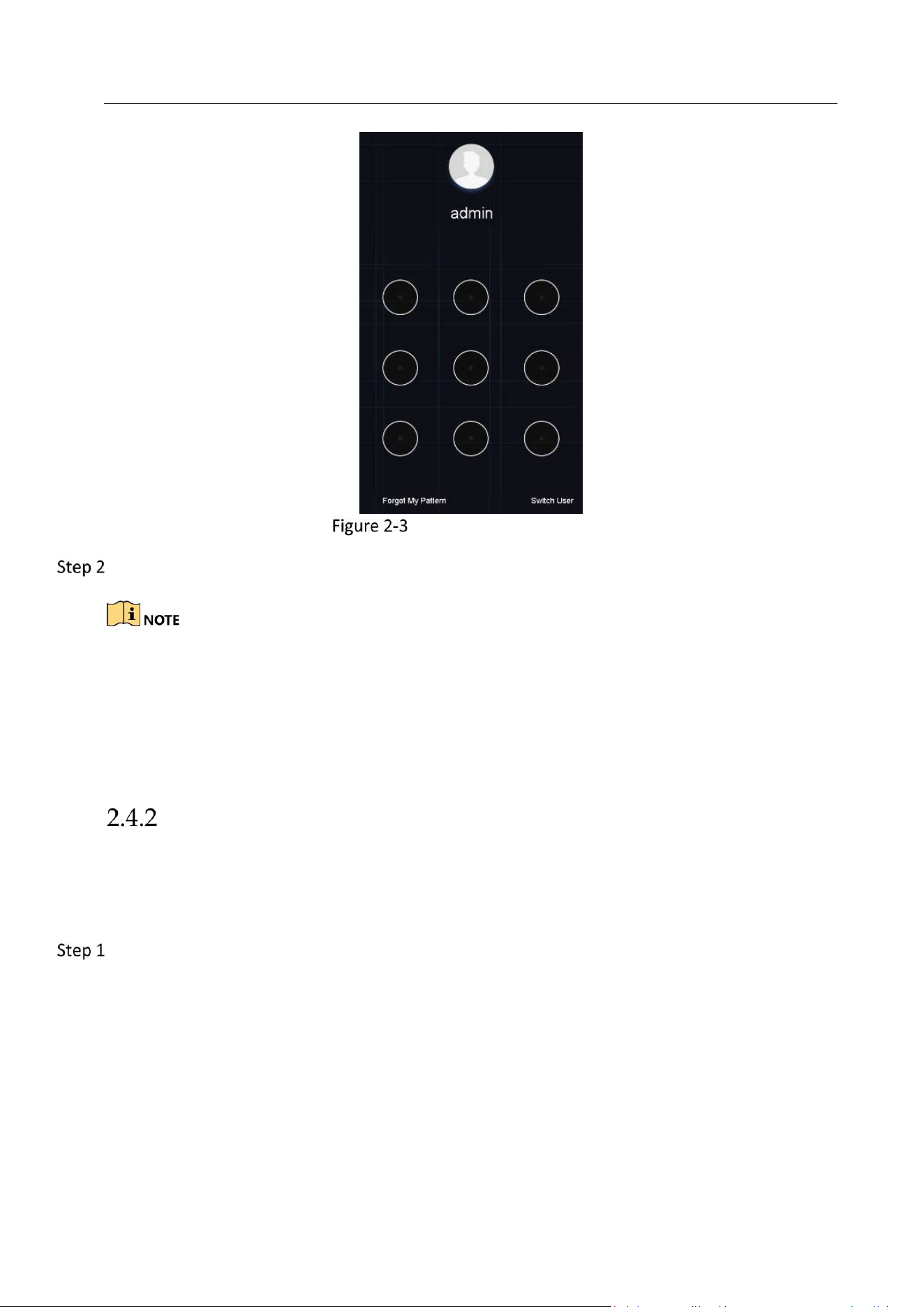
Log in to the Device
Log in via Unlock Pattern
Only the admin user has the permission to unlock the device.
Please configure the pattern first before unlocking. Please refer to Chapter 2.3 Configure
Unlock Pattern for Login.
Right click the mouse on the screen and select the menu to enter the interface.
Network Video Recorder User Manual
31
Draw the Unlock Pattern
Draw the pre-defined pattern to unlock to enter the menu operation.
If you have forgotten your pattern, you can select the Forgot My Pattern or Switch User
option to enter the normal login dialog box.
When the pattern you draw is different from the pattern you have configured, you should
try again.
If you have drawn the wrong pattern for more than 5 times, the system will switch to the
normal login mode automatically.
Log in via Password
Purpose:
If device has logged out, you must login the device before operating the menu and other
functions.
Enter User Name.

Network Video Recorder User Manual
32
Login Interface
Enter Password.
Click OK to log in.
When you forget the password of the admin, you can click Forgot Password to reset the
password.
In the Login dialog box, if you enter the wrong password for 7 times, the current user
account will be locked for 60 seconds.
Enter Wizard to Configure Quick Basic Settings
By default, the Setup Wizard starts once the device has loaded.
The Setup Wizard can walk you through some important settings of the device. If you don’t want
to use the Setup Wizard at that moment, click Exit.
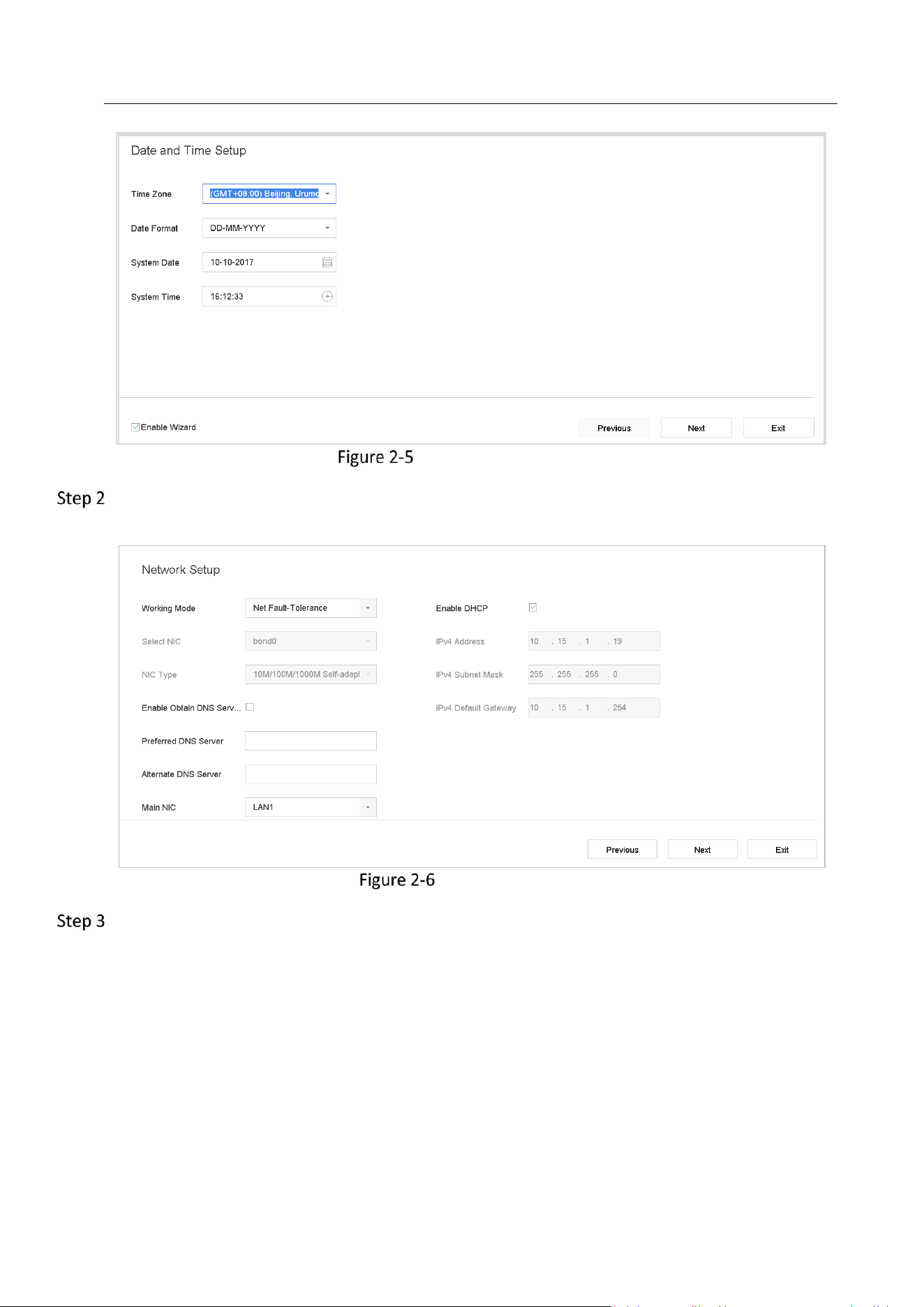
Configure the date and time on the Date and Time Setup interface.
Network Video Recorder User Manual
33
Date and Time Settings
After the time settings, click Next to enter the Network Setup Wizard window, as shown in the
following figure.
Network Settings
Click Next after you configured the network parameters, which takes you to the HDD
Management window.
Network Video Recorder User Manual
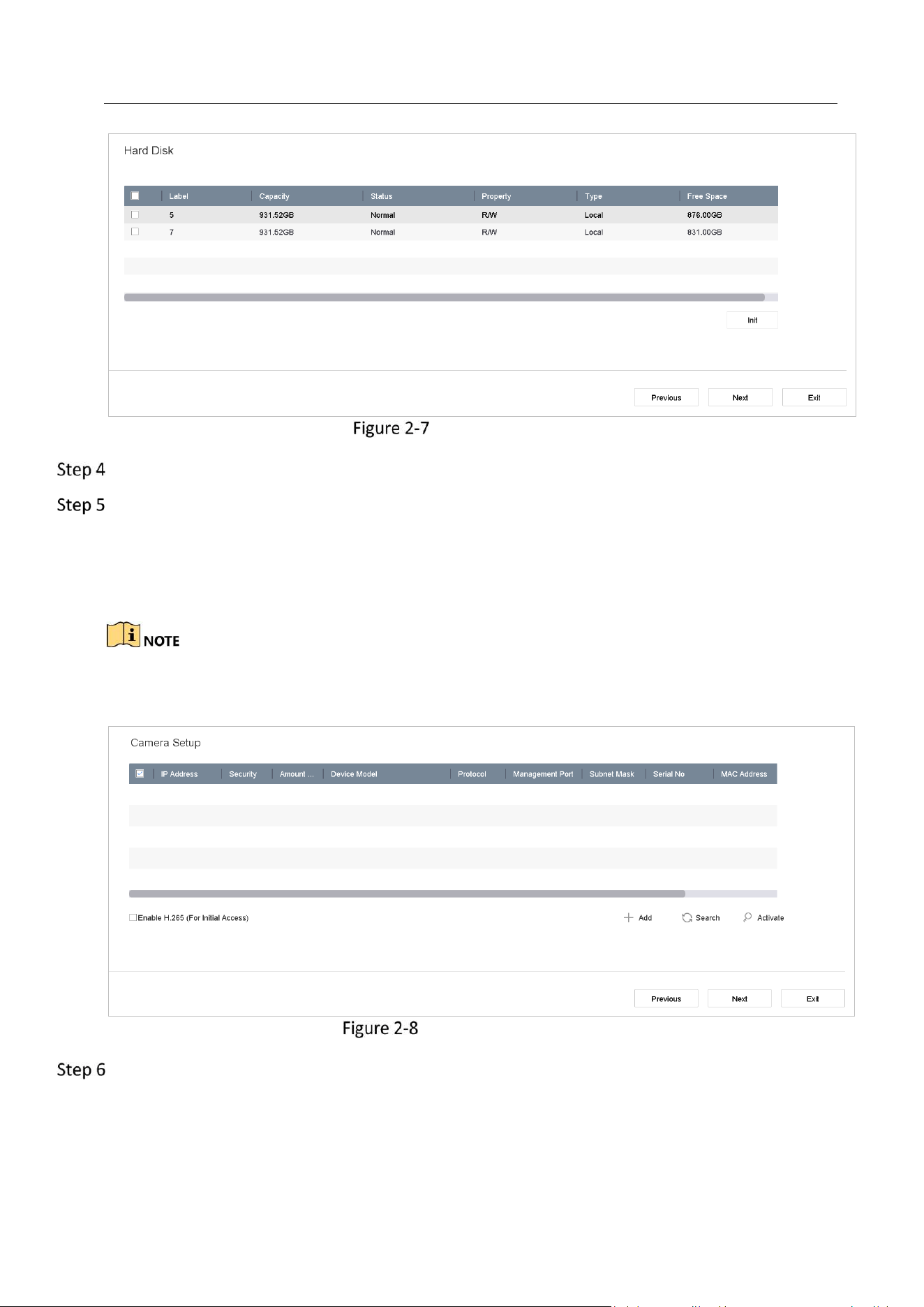
34
HDD Management
To initialize the HDD, click the Init button. Initialization removes all the data saved in the HDD.
Click Next. You enter the Camera Setup interface to add the IP cameras.
1) Click Search to search the online IP Camera. Before adding the camera, make sure the IP
camera to be added is in active status.
2) Click the Add to add the camera.
If the camera is in inactive status, you can select the camera from the list and click Activate to
activate the cameras.
Search for IP Cameras
Enter the Platform Access and configure the Hik-Connect settings.
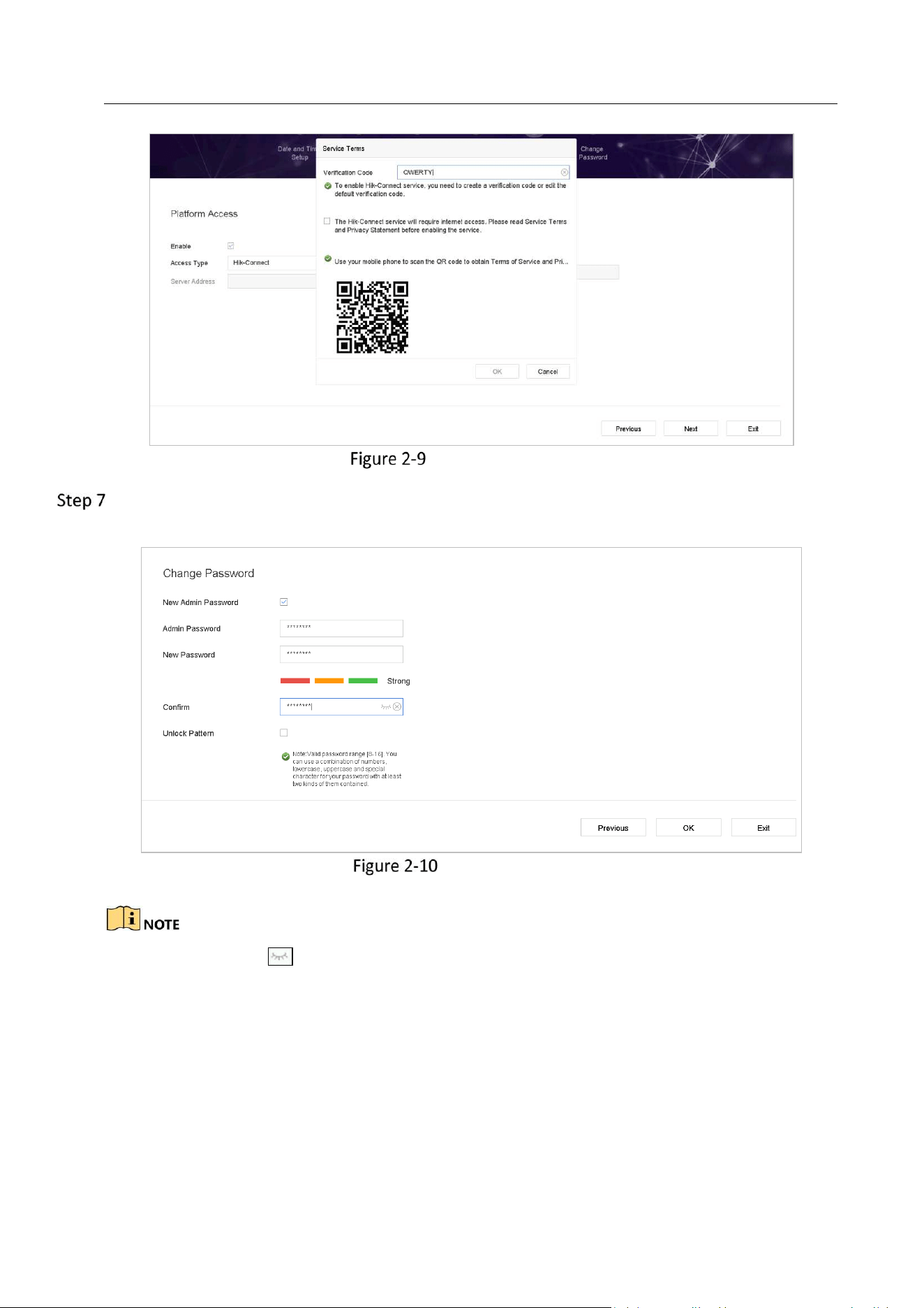
Network Video Recorder User Manual
35
Hik-Connect Access
Click Next to enter the Change Password interface to create the new admin password if
required.
Change Password
You can enter click the to show the characters input.
1) Check the checkbox of New Admin Password.
2) Enter the original password in the text field of Admin Password
3) Input the same password in the text field of New Password and Confirm.
4) Check the Unlock Pattern to enable the unlock pattern login.
Network Video Recorder User Manual
36
We highly recommend you create a strong password of your own choosing (Using a minimum of
8 characters, including at least three of the following categories: upper case letters, lower case
letters, numbers, and special characters.) in order to increase the security of your product. And
we recommend you reset your password regularly, especially in the high security system, resetting
the password monthly or weekly can better protect your product.
Click OK to complete the startup Setup Wizard.
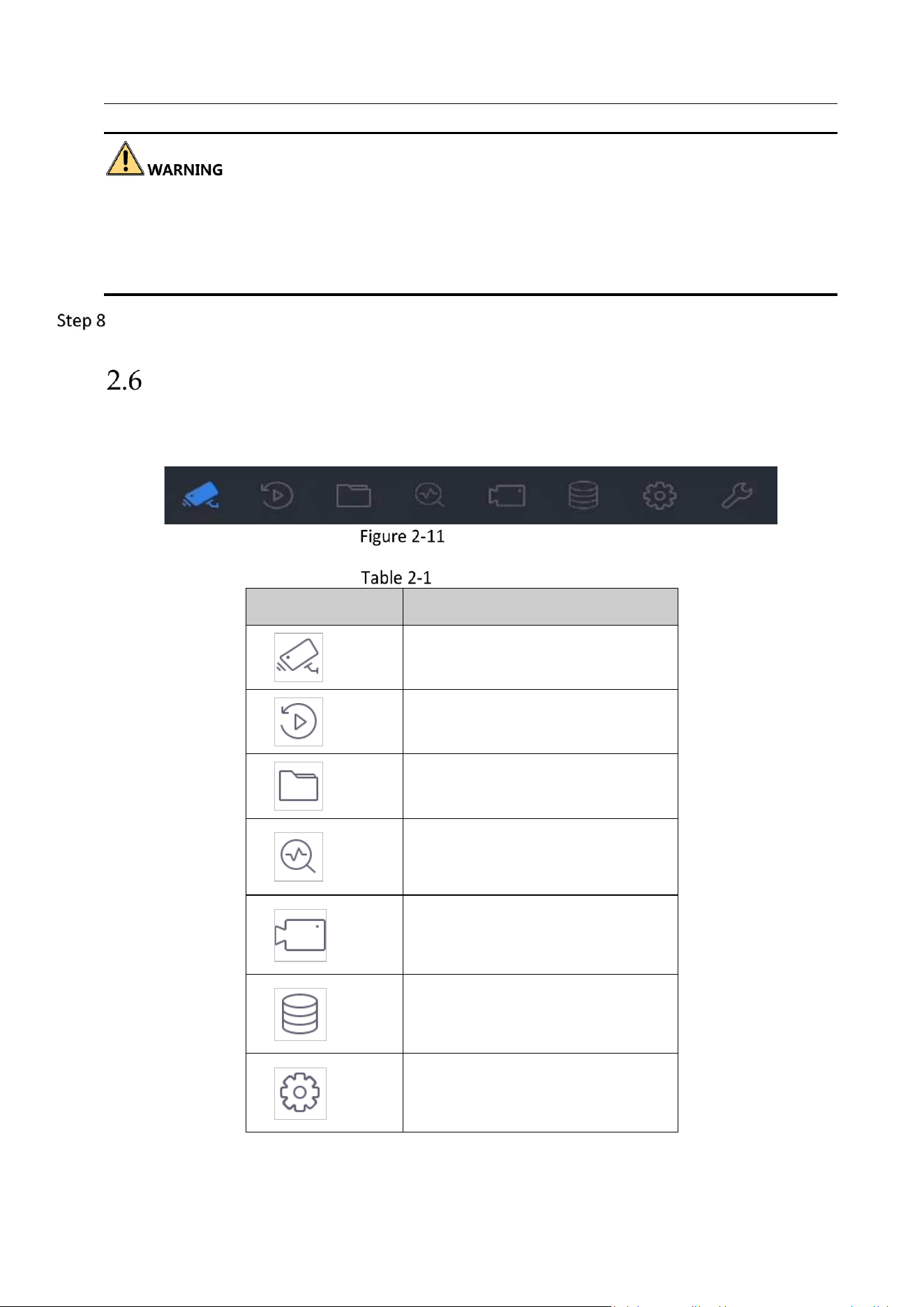
Enter Main Menu
After you have completed the wizard, you can right click on the screen to enter the main menu
bar. Refer to the following figure and table for the description of main menu and sub-menus.
Main Menu Bar
Description of Icons
Icon
Description
Live View
Playback
File Management
Smart Analysis
Camera Management
Storage Management
System Management

Network Video Recorder User Manual
37
System Maintenance:
System Operation
Log out
Purpose:
After logging out, the monitor turns to the live view mode and if you want to perform any
operations, you need to enter user name and password to log in again.
Click on the menu bar.
Click Logout.
After you have logged out the system, menu operation on the screen is invalid. It is required to
input a user name and password to unlock the system.
Shut Down the Device
Click on the menu bar.
Click the Shutdown button.
Click the Yes button.
Do not press the POWER button again when the system is shutting down.
Reboot the Device
From the Shutdown menu, you can also reboot the device.
Click on the menu bar.
Click Reboot to reboot the device.
Network Video Recorder User Manual
38
Chapter 3 Camera Management
Add the IP Cameras
Add the IP Camera Manually
Purpose:
Before you can get live video or record the video files, you should add the network cameras to
the connection list of the device.
Before you start:
Ensure the network connection is valid and the IP camera has been activated.
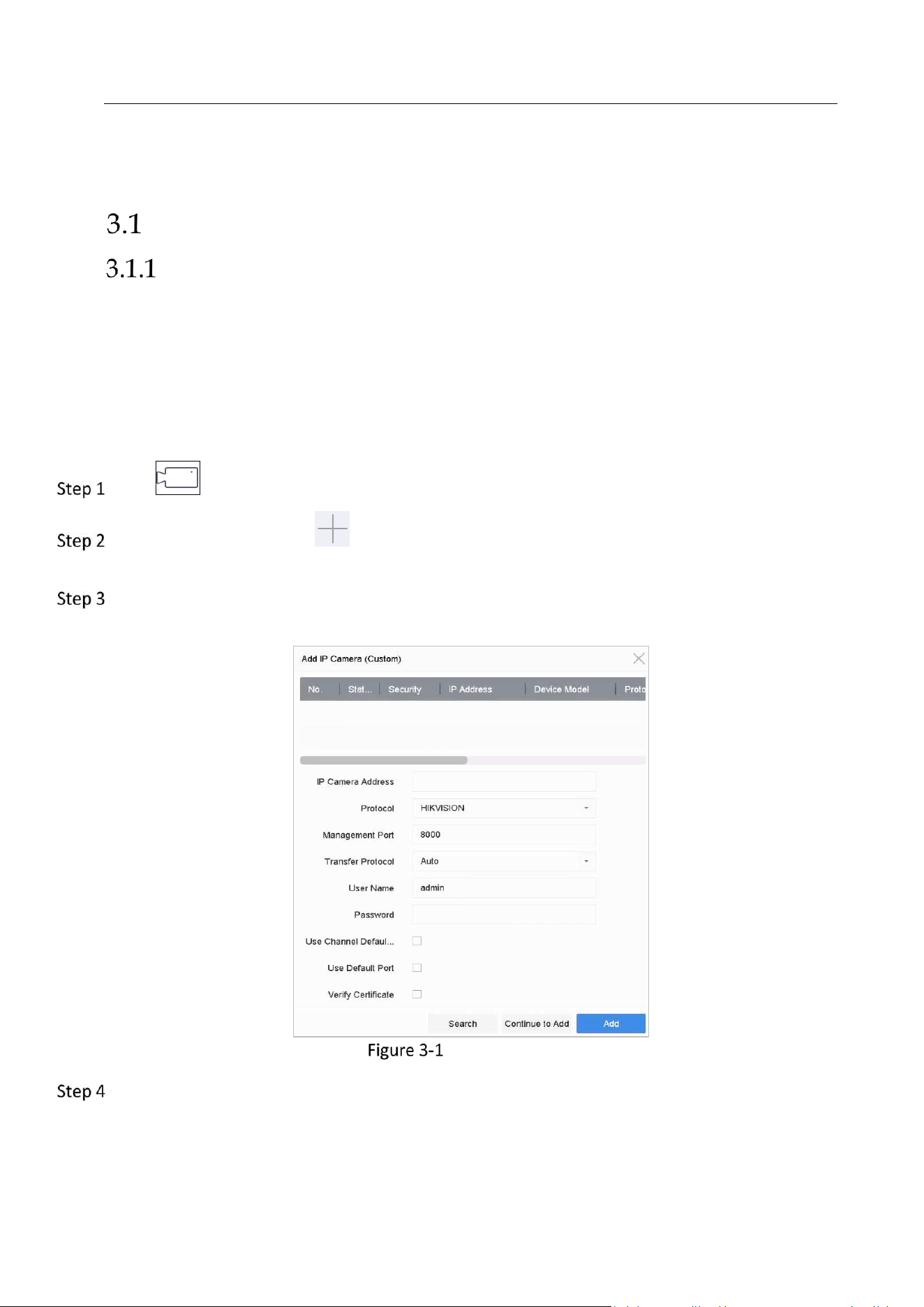
Click on the main menu.
Click Custom Add, or click in the idle channel window to enter the Add IP Camera
interface.
Set IP Camera Address, Protocol, Management Port, Transfer Protocol, User Name, and
Password. Management Port ranges from 1 to 65535.
Add IP Camera
(Optional) Check Use Channel Default Password to use the default password to add the
camera.
Network Video Recorder User Manual
39
(Optional) Check Use Default Port to use the default management port to add the camera. For
SDK service, the default port value is 8000. For enhanced SDK service, the default value is 8443.
The function is only available when you use HIKVISION protocol.
(Optional) Check Verify Certificate to verify the camera with certificate. The certificate is a form
of identification for the camera that provides more secure camera authentication. It requires to
import the IP camera certificate to the NVR first when you use this function.
1) Log in the IP camera by web browser.
2) Go to Configuration > Network > Advanced Settings > HTTPS on the web browser o to
export its certificate.
3) Click Export at Export Certificate to save the certificate.
4) Log in the NVR by web browser.
5) Go to Configuration > System > Security > Trusted Root Certification Authorities >
Import.
6) Click Import to import the IP camera certificate.
The function is only available when you use HIKVISION protocol.
Click Add to finish the adding of the IP camera.
(Optional) Click Continue to Add to continue to add other IP cameras.
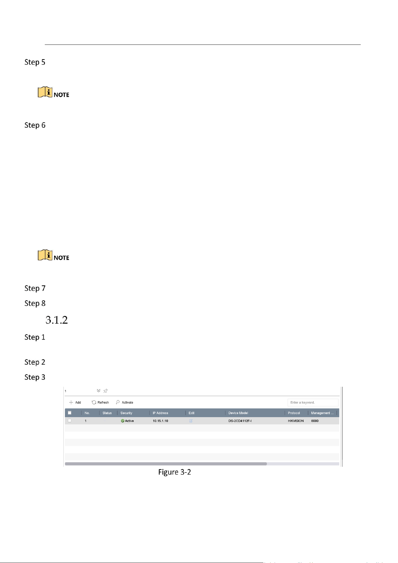
Add the Automatically Searched Online IP Cameras
On the Camera Management interface, click the Online Device panel to expand the Online
Device interface.
Select the automatically searched online devices.
Click Add.
Add IP Camera
Network Video Recorder User Manual
40
If the IP camera to add has not been actiavated, you can activate it from the IP camera list on the
camera management interface.
Enable the H.265 Stream Access
The device can automatically switch to the H.265 stream of IP camera (which supports H.265
video format) for the initial access.
Go to More Settings > H.265 Auto Switch Configuration.
Check Enable H.265 (For Initial Access).
Click OK.
Upgrade the IP Camera
The IP camera can be remotely upgraded through the device.
Plug the U-flash drive with the IP camera’s firmware upgrade file to the device.
On the camera management interface, select a camera.
Go to More Settings > Upgrade at the top taskbar.
Select the firmware upgrade file from the U-flash drive.
Click Upgrade.
Result:
The IP camera will reboot automatically after the upgrading completes.
Configure the Customized Protocols
Purpose
To connect the network cameras which are not configured with the standard protocols, you can
configure the customized protocols for them. The system provides 16 customized protocols.
Click More Settings > Protocol at the top taskbar to enter the protocol management interface.
Network Video Recorder User Manual
41
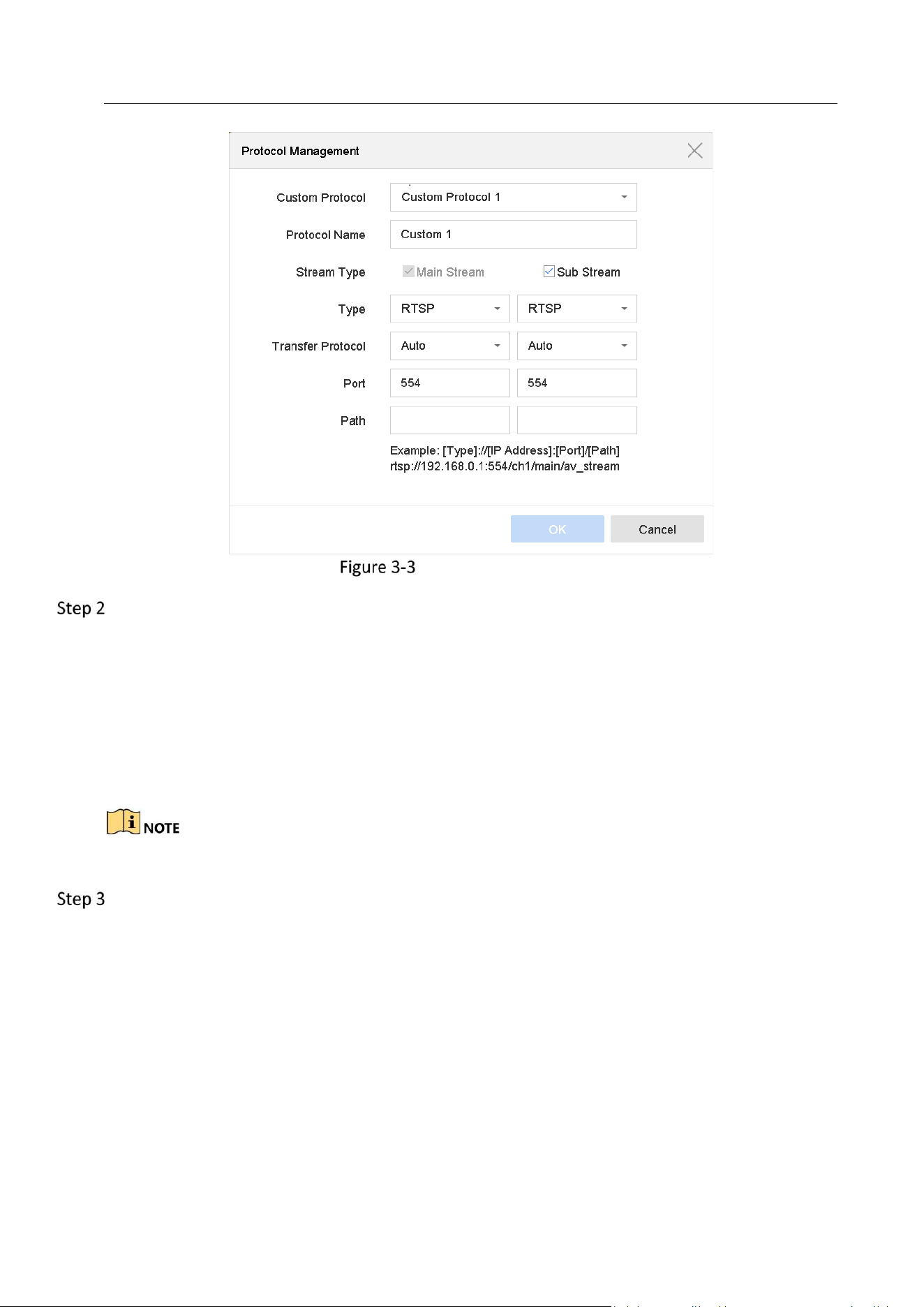
Protocol Management
Select the protocol type of transmission and choose the transfer protocols.
Type: The network camera adopting custom protocol must support getting stream through
standard RTSP.
Path: you have to contact the manufacturer of the network camera to consult the URL
(uniform resource locator) for getting main stream and sub-stream.
The format of the URL is: [Type]://[IP Address of the network camera]:[Port]/[Path].
Example: rtsp://192.168.1.55:554/ch1/main/av_stream.
The protocol type and the transfer protocols must be supported by the connected IP camera.
Click OK to save the settings.
Result:
After adding the customized protocols, you can see the protocol name is listed in the drop-down
list.
Network Video Recorder User Manual
42
Chapter 4 Camera Settings
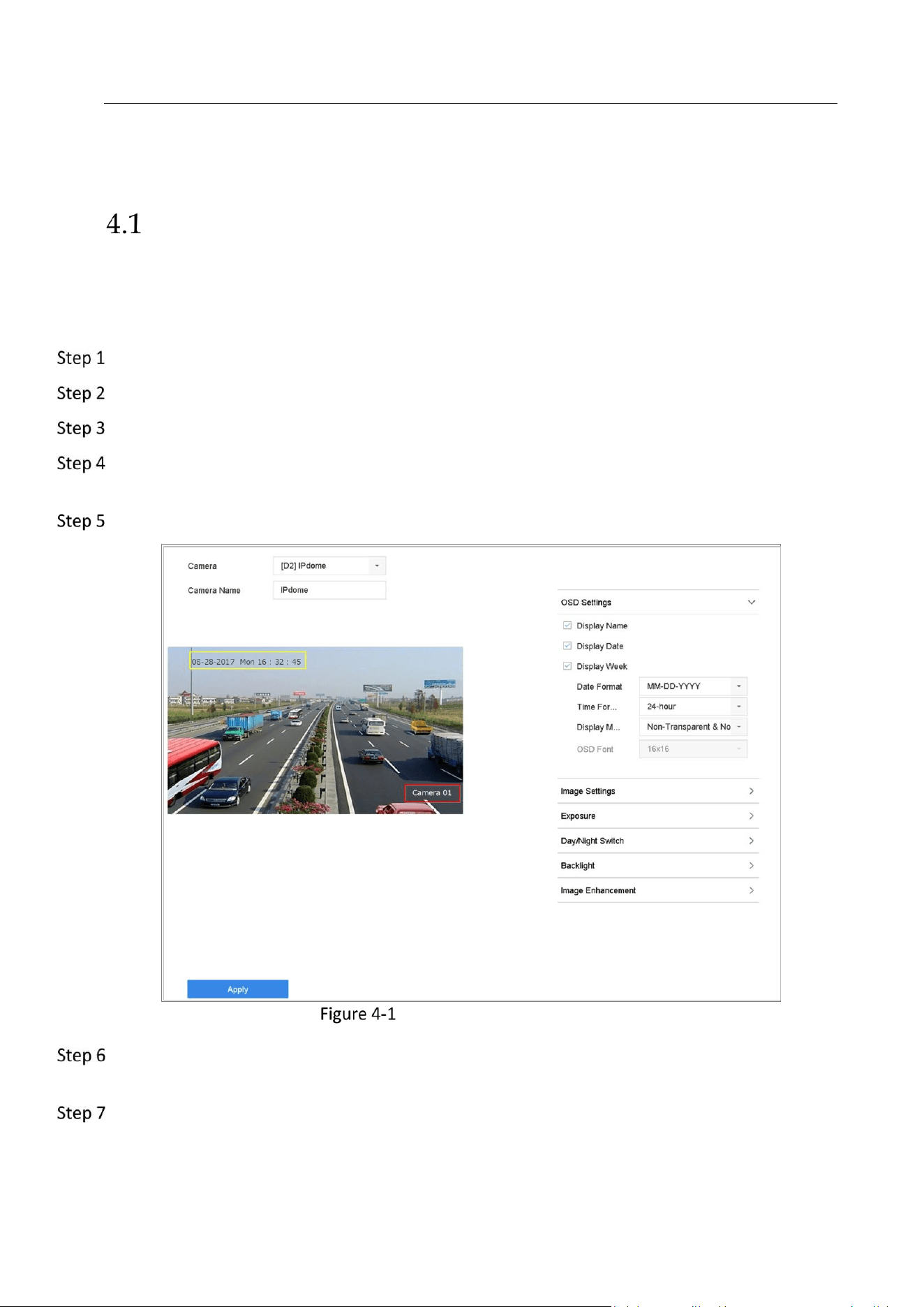
Configure OSD Settings
Purpose:
You can configure the OSD (On-screen Display) settings for the camera, including date/time,
camera name, etc.
Go to Camera > Display.
Select the camera from the drop-down list.
Edit the name in the Camera Name text field.
Check the checkbox of the Display Name, Display Date and Display Week if you want to show
the information on the image.
Set the date format, time format, and display mode.
OSD Configuration Interface
You can use the mouse to click and drag the text frame on the preview window to adjust the
OSD position.
Click the Apply button to apply the settings.
Network Video Recorder User Manual
43
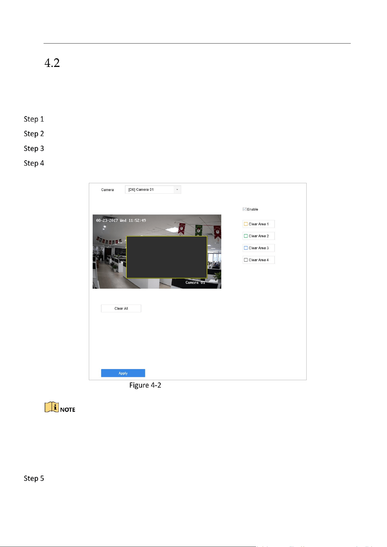
Configure Privacy Mask
Purpose:
The privacy mask can be used to protect personal privacy by concealing parts of the image from
view or recording with a masked area.
Go to Camera >Privacy Mask.
Select the camera to set privacy mask.
Click the checkbox of Enable to enable this feature.
Use the mouse to draw a zone on the window. The zones will be marked with different frame
colors.
Privacy Mask Settings Interface
Up to 4 privacy masks zones can be configured and the size of each area can be adjusted.
Related Operation:
The configured privacy mask zones on the window can be cleared by clicking the corresponding
Clear Zone1-4 icons on the right side of the window, or click Clear All to clear all zones.
Click Apply to save the settings.

Network Video Recorder User Manual
44
Configure the Video Parameters
Purpose:
You can customize the image parameters including the brightness, contrast, saturation for the
live view and recording effect.
Go to Camera > Display.
Select the camera from the drop-down list.
Adjust the slider or click on the up/down arrow to set the value of the brightness, contrast or
saturation.
Click Apply to save the settings.
Configure the Day/Night Switch
The camera can be set to day, night or auto switch mode according to the surrounding
illumination conditions.
Go to Camera > Display.
Select the camera from the drop-down list.
Select the day/night switch mode to Day, Night, Auto or Auto-Switch.
Auto: The camera switches between the day mode and the night mode according to the
illumination automatically.
The sensitivity ranges from 0 to 7, and the higher sensitivity results in the more easily to trigger
the mode switch.
The switch time refers to the interval time between the day/night switch. You can set it from 5
sec to 120 sec.
Auto-Switch: The camera switches the day mode and the night mode according to the start
time and end time you set.
Click the Apply to save the settings.
Configure IP Camera Time Sync
The device can automatically synchronize the time of connected IP camera after enabling this
function.
Go to Camera > Camera > IP Camera.
Position the cursor on the window of the IP camera and click .
Check Enable IP Camera Time Sync.

Network Video Recorder User Manual
45
Click OK.
Configure Other Camera Parameters
For the connected camera, you can configure the camera parameters including the exposure
mode, backlight and image enhancement.
Go to Camera > Display.
Select the camera from the drop-down list.
Configure the camera parameters.
Exposure: Set the exposure time (1/10000 to 1 sec) of camera. The larger exposure value
results in the brighter image.
Backlight: Set the wide dynamic range (0 to 100) of the camera. When the surrounding
illumination and the object have larger difference in brightness, you should set the WDR
value.
Image Enhancement: For optimized image contrast enhancement.
Click the Apply to save the settings.

Network Video Recorder User Manual
46
Chapter 5 Live View
Live view shows you the video image getting from each camera in real time.
Start Live View
Click on the main menu bar to enter the live view.
You can select a window and double click a camera from the list to play the video from the
camera in the selected window.
Use the toolbar at the playing window bottom to realize the capture, instant playback, audio
on/off, digital zoom, live view strategy, show information and start/stop recording, etc.
Digital Zoom
Digital Zoom is for zooming in the live image. You can zoom in the image to different
proportions (1 to 16X).
In the live view mode, click from the toolbar to enter the digital zoom interface.
You can move the sliding bar or scroll the mouse wheel to zoom in/out the image to different
proportions (1 to 16X).
Digital Zoom
Fisheye View
The device supports the fisheye expansion for the connected fisheye camera in live view or
playback mode.
Network Video Recorder User Manual
47
The fisheye expansion view feature is supported by the DS-7600/7700/8600/9600-I (/P)
series device only.
The connected camera must support the fisheye view.
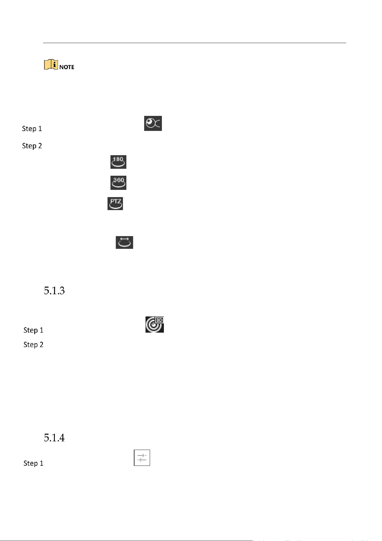
In the live view mode, click the to enter the fisheye expansion mode.
Select the expansion view mode.
180° Panorama ( ): Switch the live view image to the 180° panorama view.
360° Panorama ( ): Switch the live view image to the 360° panorama view.
PTZ Expansion ( ): The PTZ Expansion is the close-up view of some defined area in the
fisheye view or panorama expansion, and it supports the electronic PTZ function, which is
also called e-PTZ.
Radial Expansion ( ): In the radial expansion mode, the whole wide-angle view of the
fisheye camera is displayed. This view mode is called Fisheye View because it approximates
the vision of a fish’s convex eye. The lens produces curvilinear images of a large area, while
distorting the perspective and angles of objects in the image.
3D Positioning
3D Positioning (for I series device) is for zooming in/out the specific area of live image.
In the live view mode, click the to enter the 3D positioning mode.
Operate the zoom in/out in the image.
Zoom in
Use the left key of mouse to click on the desired position in the video image and drag a
rectangle area in the lower right direction to realize zoom in.
Zoom out
Use the left key of mouse to drag a rectangle area in the upper left direction to move the
position to the center and enable the rectangle area to zoom out.
Live View Strategy
In the live view mode, click to enter the digital zoom operation interface in full screen
mode.
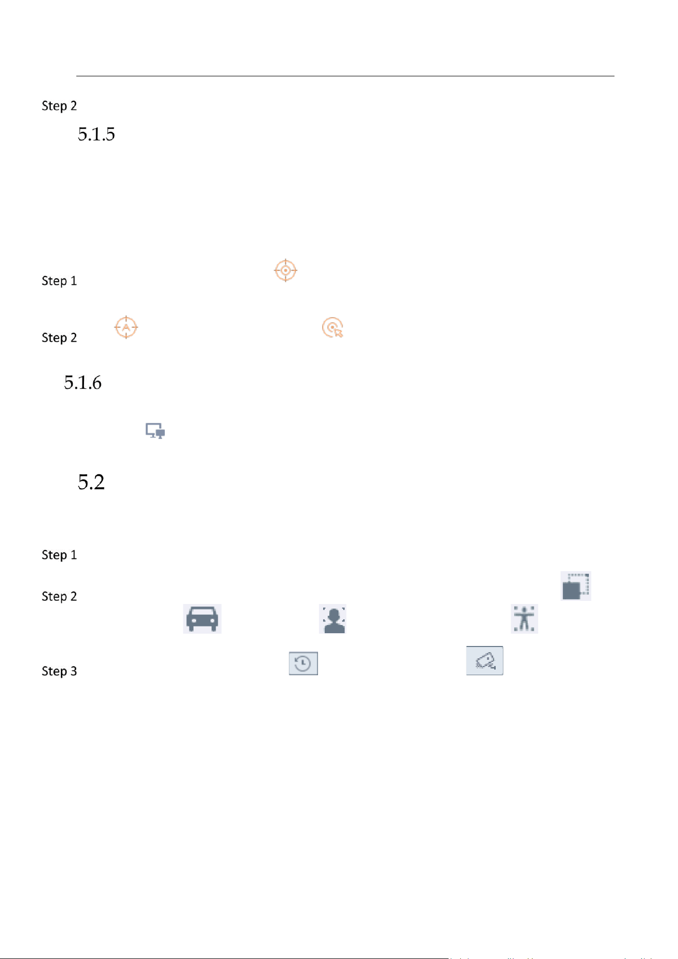
Network Video Recorder User Manual
48
Select the live view strategy to Real-time, Balanced or Fluency.
Target Tracking
Purpose:
The function is only available for PanoVu series network camera.
Before you start:
Add a 24 MP PanoVu series network camera to channel 1, 2, 3, or 4.
Enter live view interface and click of PanoVu series network camera. The live view
window will be divided into 1+5 windows to show details.
Click to start auto-tracking. Or click and drag to select five areas in PanoVu series
network camera.
Switch Main/Auxiliary Port
Only the image displaying at the main port can enter main menu and achieve device operation.
You can click in Live View mode to switch the main/auxiliary port.
Target Detection
In live view mode, the target detection function can be used to detect the human
motoion/face/vechicle/human body during the last 5 seconds and the following 10 seconds.
In the live view mode, click Target Detection tab to enter the target detection interface.
Check the checkbox of the icons to select different detection types: motion detection ( ),
vehicle detection ( ), face detection ( ) and human body detection ( ).
You can select the historical analysis ( ) or the real-time analysis ( ) to obtain the
results.
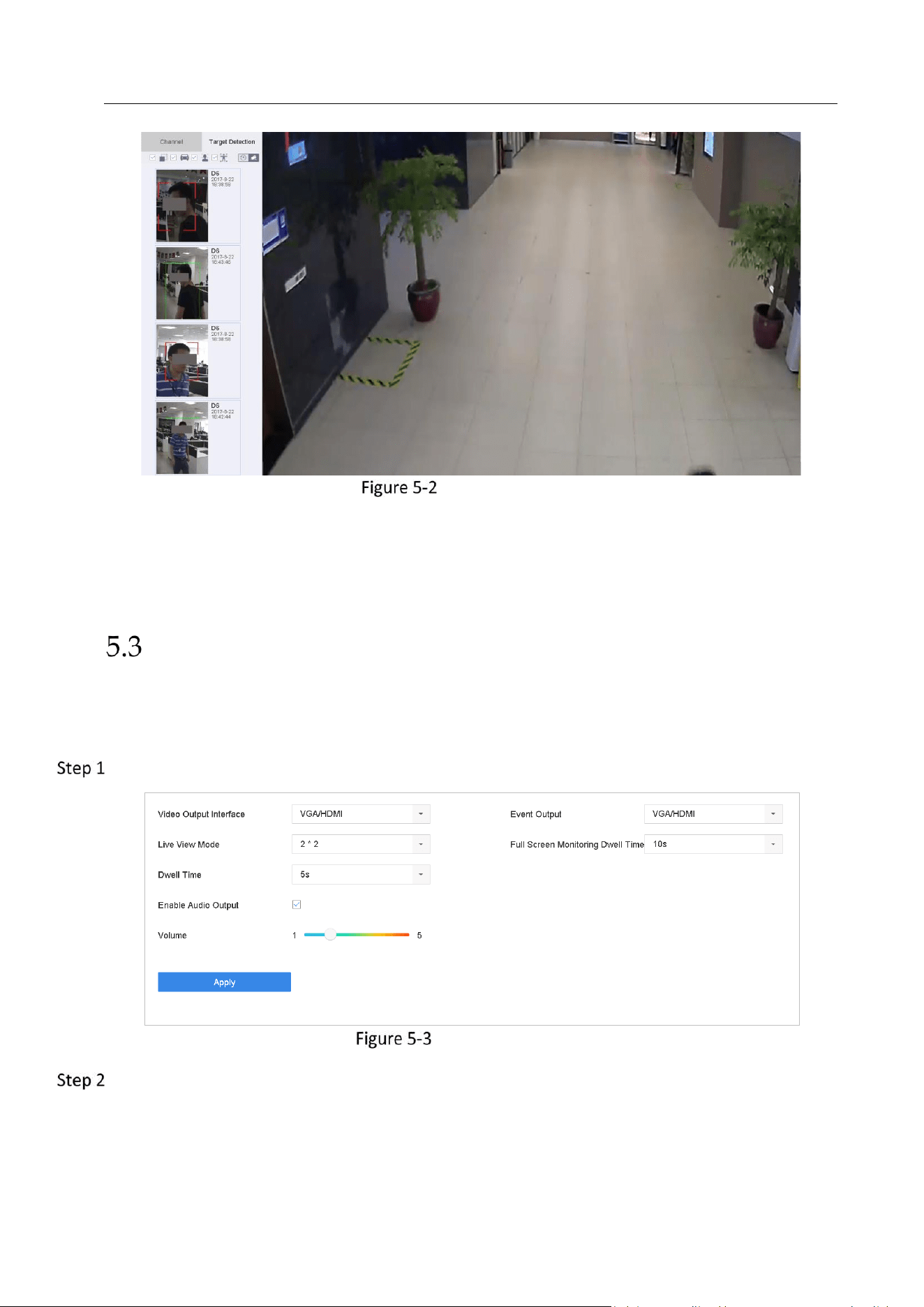
Network Video Recorder User Manual
49
Target Detection
Result:
The smart analysis results of the detection are displayed in the list. Optionally, click a result in
list to play the related video.
Configure Live View Settings
Live View settings can be customized according to different needs. You can configure the output
interface, dwell time for screen to be shown, mute or turning on the audio, the screen number
for each channel, etc.
Go to System > Live View > General.
Live View-General
Configure the live view parameters.
Video Output Interface: Select the video output to configure.
Live View Mode: Select the display mode for live view, e.g., 2*2, 1*5, etc.
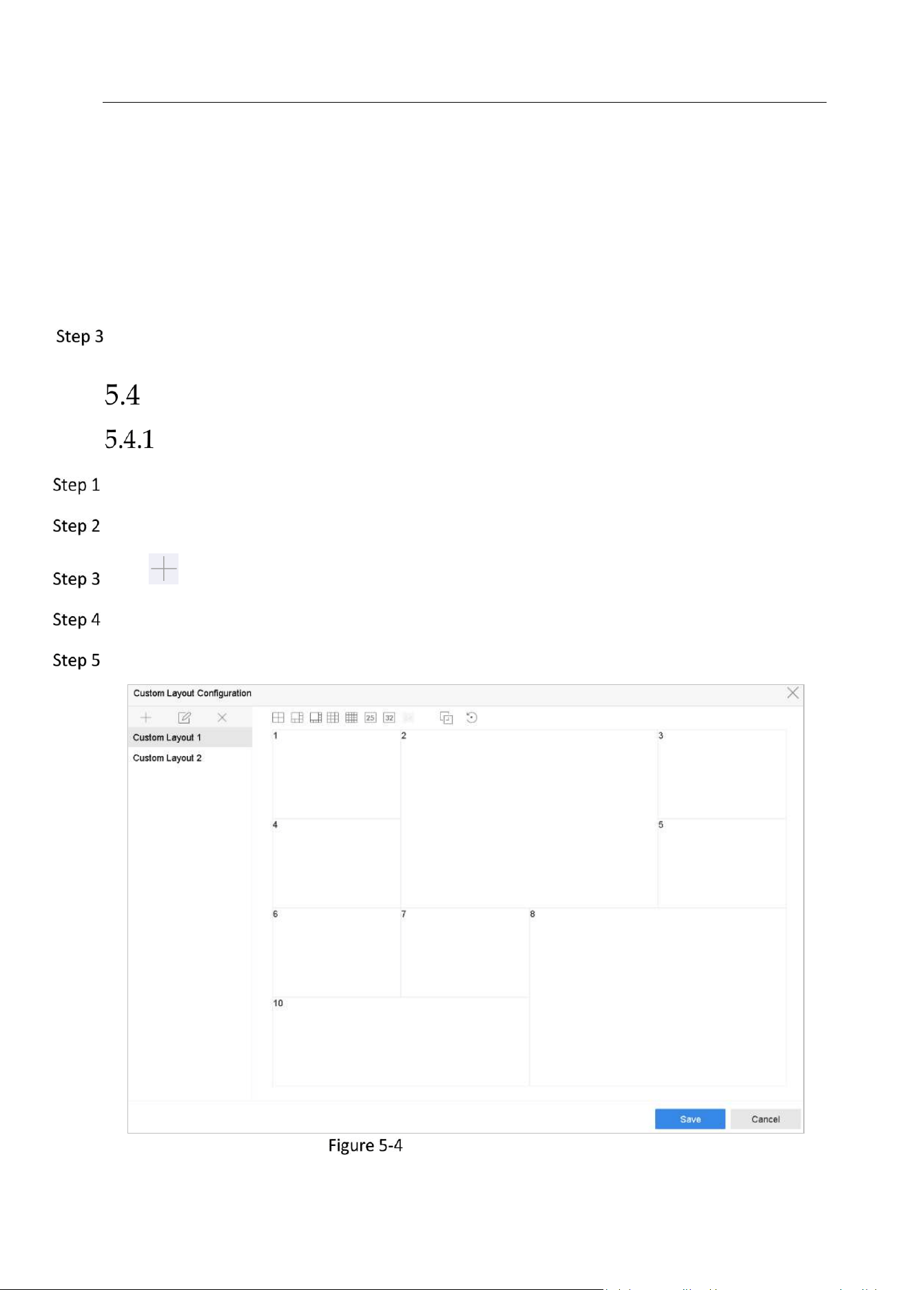
Network Video Recorder User Manual
50
Dwell Time: The time in seconds to dwell between switching of cameras when enabling auto-
switch in Live View.
Enable Audio Output: Enable/disable audio output for the selected video output.
Volume: Adjust the volume of live view, playback and two-way audio for the selected output
interface.
Event Output: Select the output to show event video.
Full Screen Monitoring Dwell Time: Set the time in seconds to show alarm event screen.
Click OK to save the settings.
Configure Live View Layout
Configure Custom Live View Layout
Go to System > Live View > View.
Click Set Custom Layout.
Click on the Custom Layout Configuration interface.
Edit the layout name.
Select a window division mode from the toolbar.
Configure Live View Layout
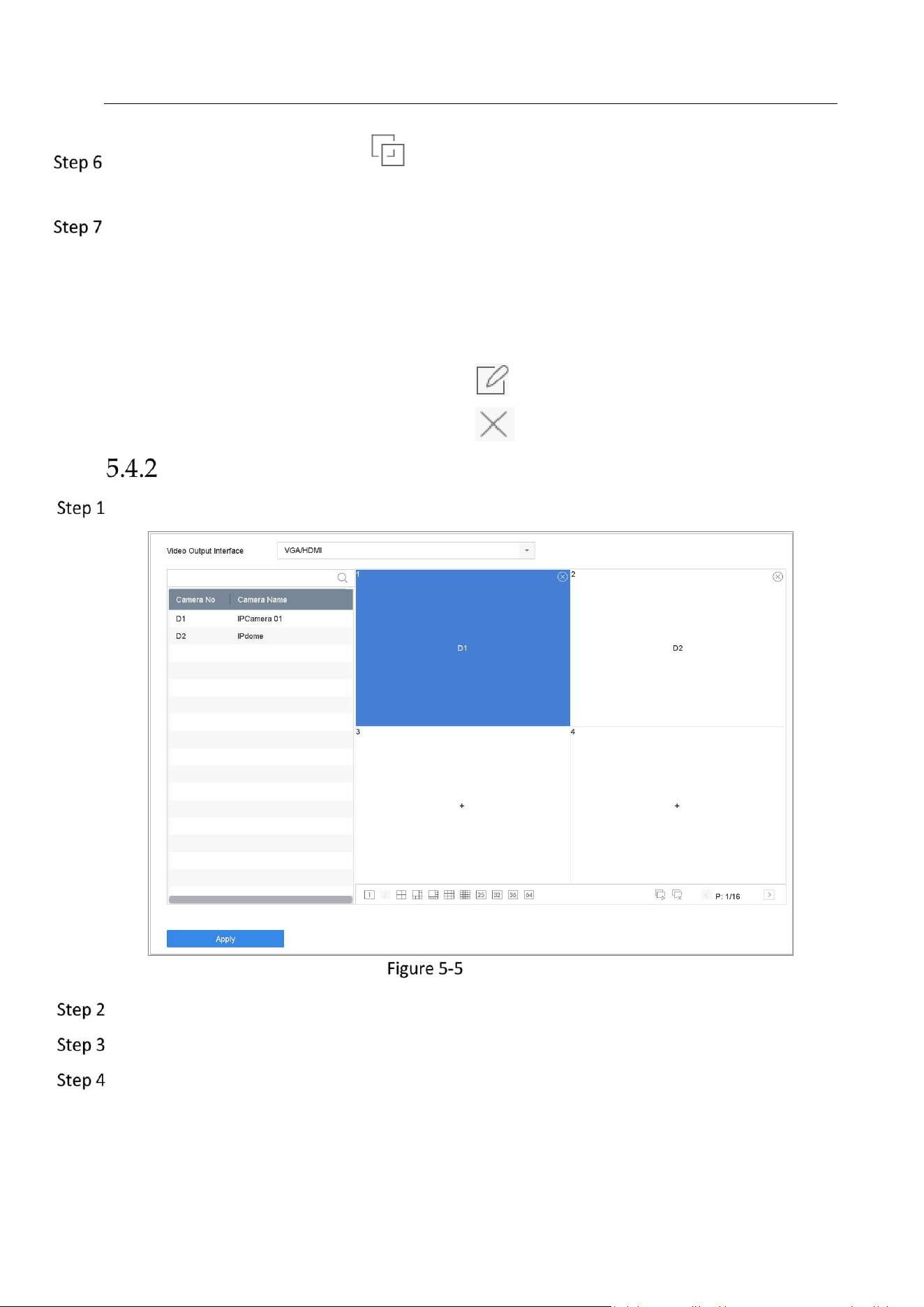
Network Video Recorder User Manual
51
Select multiple windows and click to join the windows. The selected windows must be in
rectangle area.
Click Save.
Result:
The successfully configured view layout is displayed in the list.
Related Operations:
Select a live view layout from the list and click to edit the name.
Select a live view layout from the list and click to delete the name.
Configure Live View Mode
Go to System> Live View>View Settings.
Live View
Select the video output interface, e.g., HDMI/ VGA or channel-zero.
Select a window division mode from the toolbar.
Select a division window, and double-click on the camera from the list to set the camera to the
window.
You can enter the number in the text field to quickly search the camera from the list.

Network Video Recorder User Manual
52
You can also click-and-drag the camera to the desired window on the live view interface to set the
camera order.
Related Operation:
1) Click button to start live view for all the channels.
2) Click to stop all the live view.
Click Apply to save the settings.
Configure Auto-Switch of Cameras
You can set the auto-switch of cameras to play in different display modes.
Go to System > Live View > General.
Set the video output interface, live view mode and dwell time.
Video Output Interface: Select the video output interface.
Live View Mode: Select the display mode for live view, e.g., 2*2, 1*5, etc.
Dwell Time: The time in seconds to dwell between switching of cameras when enabling auto-
switch. The range is from 5s to 300s.
Go to View Settings to set the view layout.
Click OK to save the settings.
Configure Channel-zero Encoding
Purpose:
You can enable the channel-zero encoding when you need to get a remote view of many
channels in real time from web browser or CMS (Client Management System) software, in order
to decrease the bandwidth requirement without affecting the image quality.
Go to System > Live View > General.
Select the video output interface to Channel-Zero.
Go to System > Live View > Channel-Zero.
Check the checkbox to enable the channel-zero.
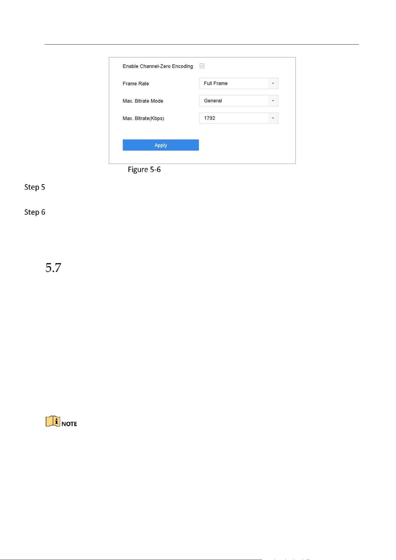
Network Video Recorder User Manual
53
Live View- Channel-Zero Encoding
Configure the Frame Rate, Max. Bitrate Mode and Max. Bitrate. The higher frame rate and
bitrate settings result in the higher requirement of bandwidth.
Click Apply.
Result:
You can view all of the channels in one screen using the CMS or web browser.
Using an Auxiliary Monitor
Certain features of the Live View are also available while in an Aux monitor. These features
include:
Single Screen: Switch to a full screen display of the selected camera. Camera can be selected
from a dropdown list.
Multi-screen: Switch between different display layout options. Layout options can be selected
from a dropdown list.
Next Screen: When displaying less than the maximum number of cameras in Live View, clicking
this feature will switch to the next set of displays.
Playback: Enter into Playback mode.
PTZ Control: Enter PTZ Control mode.
Main Monitor: Enter Main operation mode.
In the live view mode of the main output monitor, the menu operation is not available while Aux
output mode is enabled.
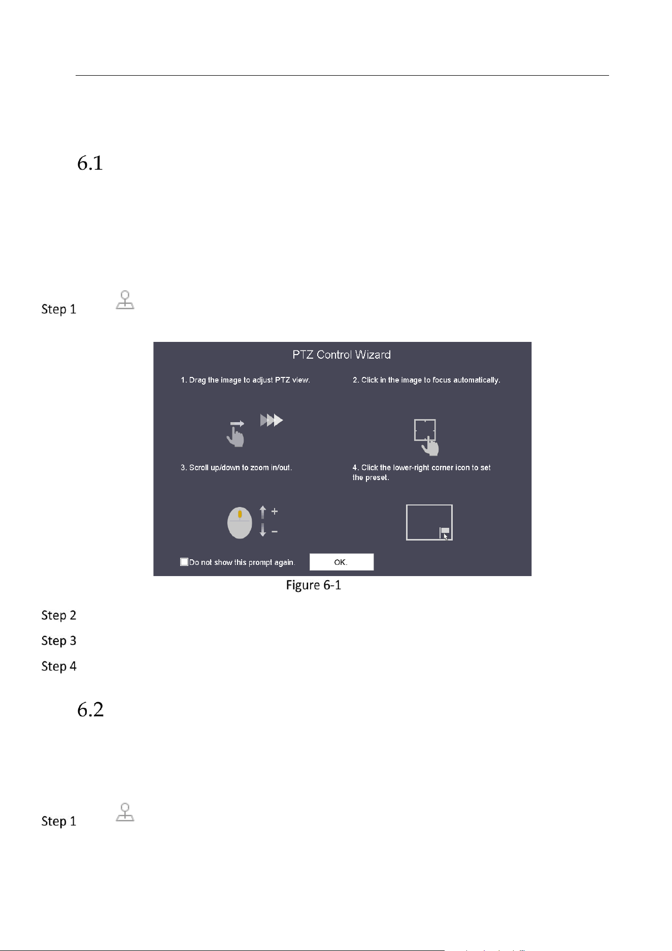
Network Video Recorder User Manual
54
Chapter 6 PTZ Control
PTZ Control Wizard
Before you start
Please make sure the connected IP camera supports the PTZ function and is properly connected.
Purpose
Follow the PTZ control wizard to guide you through the basic PTZ operation.
Click on the quick settings toolbar of the PTZ camera live view. The PTZ control wizard
pops up as below.
PTZ Control Wizard
Follow the wizard to adjust the PTZ view, focus, and zoom in/out the camera.
(Optional) Check Do not show this prompt again.
Click OK to exit.
ConfigurePTZ Parameters
Purpose
Follow the procedure to set the parameters for PTZ. The configuration of the PTZ parameters
should be done before you control the PTZ camera.
Click on the quick settings toolbar of the PTZ camera live view. The PTZ control panel
displays on the right of the interface.
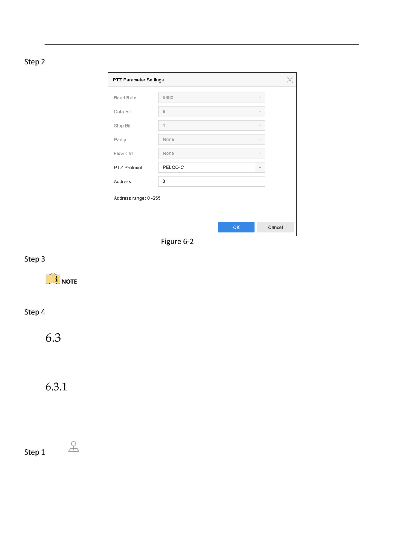
Network Video Recorder User Manual
55
Click PTZ Parameters Settings to set the PTZ parameters.
PTZ Parameters Settings
Edit the parameters of the PTZ camera.
All the parameters should be exactly the same as the PTZ camera parameters.
Click OK to save the settings.
Set PTZ Presets, Patrols & Patterns
Before you start:
Please make sure that the presets, patrols and patterns should be supported by PTZ protocols.
Set a Preset
Purpose:
Follow the steps to set the preset location which you want the PTZ camera to point to when an
event takes place.
Click on the quick settings toolbar of the PTZ camera live view.
The PTZ control panel displays on the right of the interface.
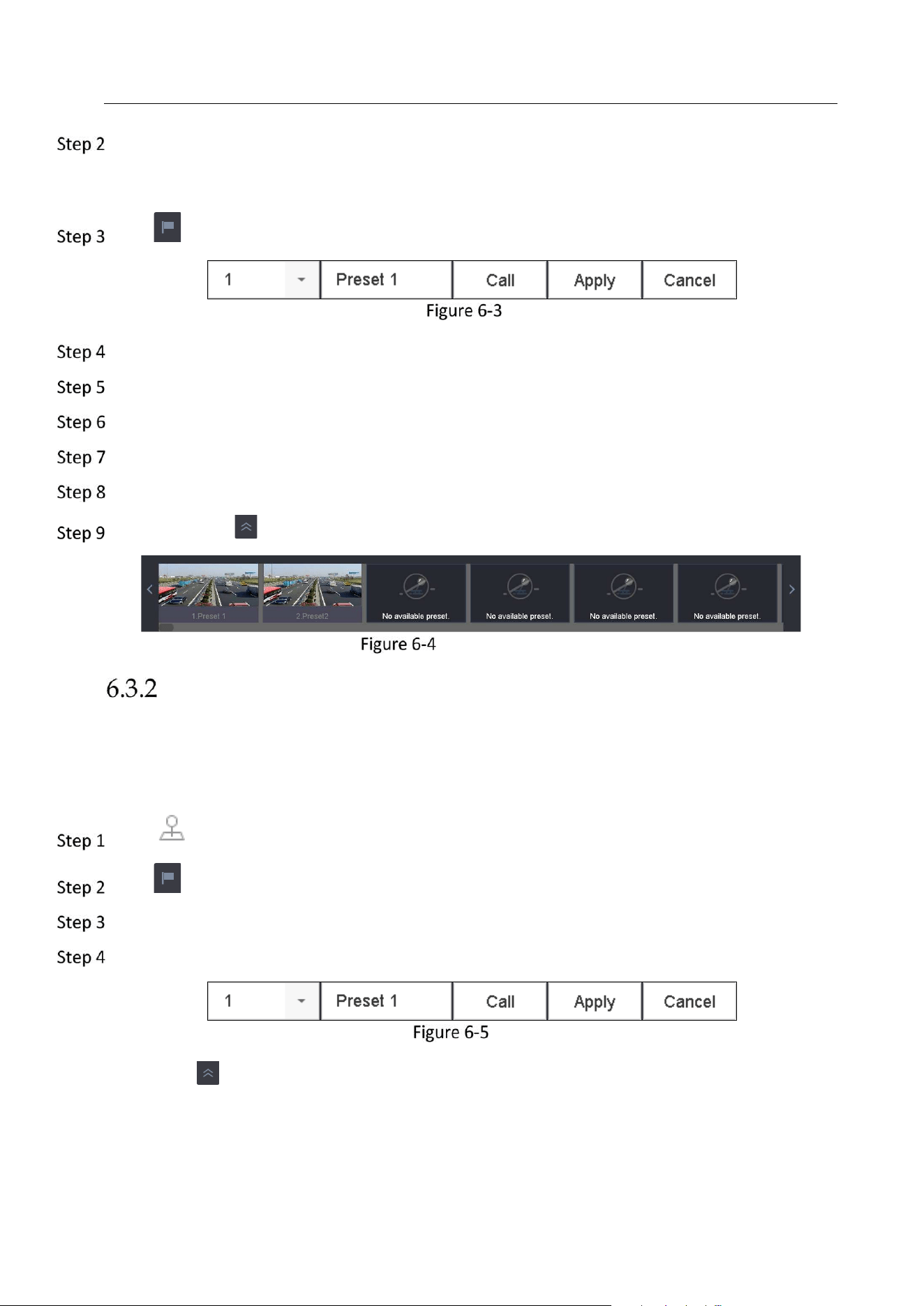
Network Video Recorder User Manual
56
Use the directional buttons on the PTZ control panel to wheel the camera to the location where
you want to set preset, and the zoom and focus operations can be recorded in the preset as
well.
Click in the lower right corner of live view to set the preset.
Set Preset
Select the preset No. (1~255) from the drop-down list.
Enter the preset name in the text field.
Click Apply to save the preset.
Repeat steps 2-6 to save more presets.
(Optional) Click Cancel to cancel the location information of the preset.
(Optional) Click in the lower right corner of live view to view the configured presets.
View the Configured Presets
Call a Preset
Purpose:
This feature enables the camera to point to a specified position such as a window when an event
takes place.
Click on the quick settings toolbar of the PTZ camera live view.
Click in the lower right corner of live view.
Select the preset No. from the drop-down list.
Click Call to call it.
Call Preset (1)
Or click in the lower right corner of live view, and click the configured preset to call it.
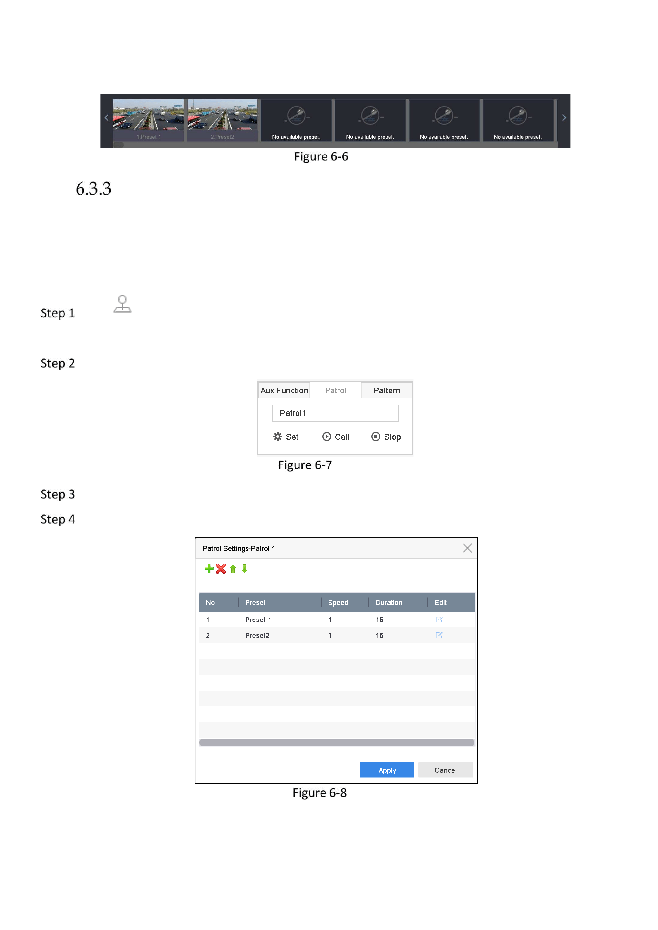
Network Video Recorder User Manual
57
Call Preset (2)
Set a Patrol
Purpose:
Patrols can be set to move the PTZ to different key points and have it stay there for a set
duration before moving on to the next key point. The key points are corresponding to the
presets.
Click on the quick settings toolbar of the PTZ camera live view.
The PTZ control panel displays on the right of the interface.
Click Patrol to configure patrol.
Patrol Configuration
Select the patrol No. in the text field.
Click Set to enter the Patrol Settings interface.
Patrol Settings
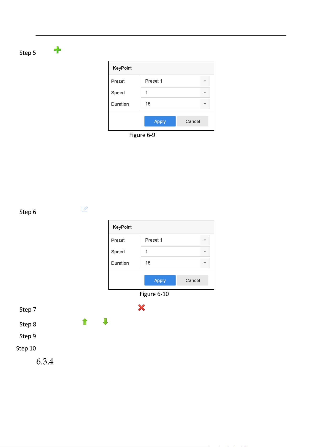
Network Video Recorder User Manual
58
Click to add key point for the patrol.
Key Point Configuration
1) Configure key point parameters.
Preset: It determines the order at which the PTZ will follow while cycling through the patrol.
Speed: It defines the speed at which the PTZ will move from one key point to the next.
Duration: It refers to the time span to stay at the corresponding key point.
2) Click Apply to save the key points to the patrol.
(Optional) Click to edit the added key point.
Edit Key Point
(Optional) Select a key point and click to delete it.
(Optional) Click or to adjust the key point order.
Click Apply to save the settings of the patrol.
Repeat steps 3-9 to set more patrols.
Call a Patrol
Purpose:
Calling a patrol makes the PTZ to move according to the predefined patrol path.
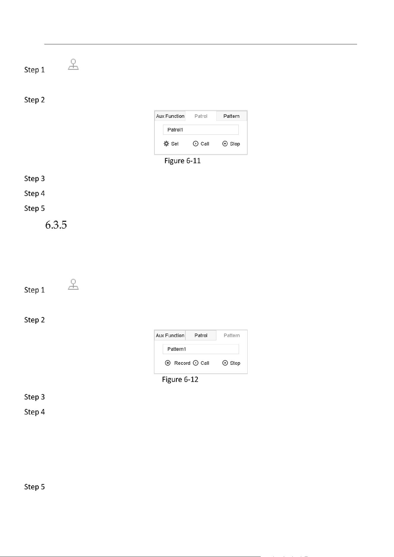
Network Video Recorder User Manual
59
Click on the quick settings toolbar of the PTZ camera live view.
The PTZ control panel displays on the right of the interface.
Click Patrol on the PTZ control panel.
Patrol Configuration
Select a patrol in the text field.
Click Call to call it.
(Optional) Click Stop to stop calling it.
Set a Pattern
Purpose:
Patterns can be set by recording the movement of the PTZ. You can call the pattern to make the
PTZ movement according to the predefined path.
Click on the quick settings toolbar of the PTZ camera live view.
The PTZ control panel displays on the right of the interface.
Click Pattern to configure pattern.
Pattern Configuration
Select the pattern No. in the text field.
Set the pattern.
1) Click Record to start recording.
2) Click corresponding buttons on the control panel to move the PTZ camera.
3) Click Stop to stop recording.
The movement of the PTZ is recorded as the pattern.
Repeat steps 3-4 to set more patterns.
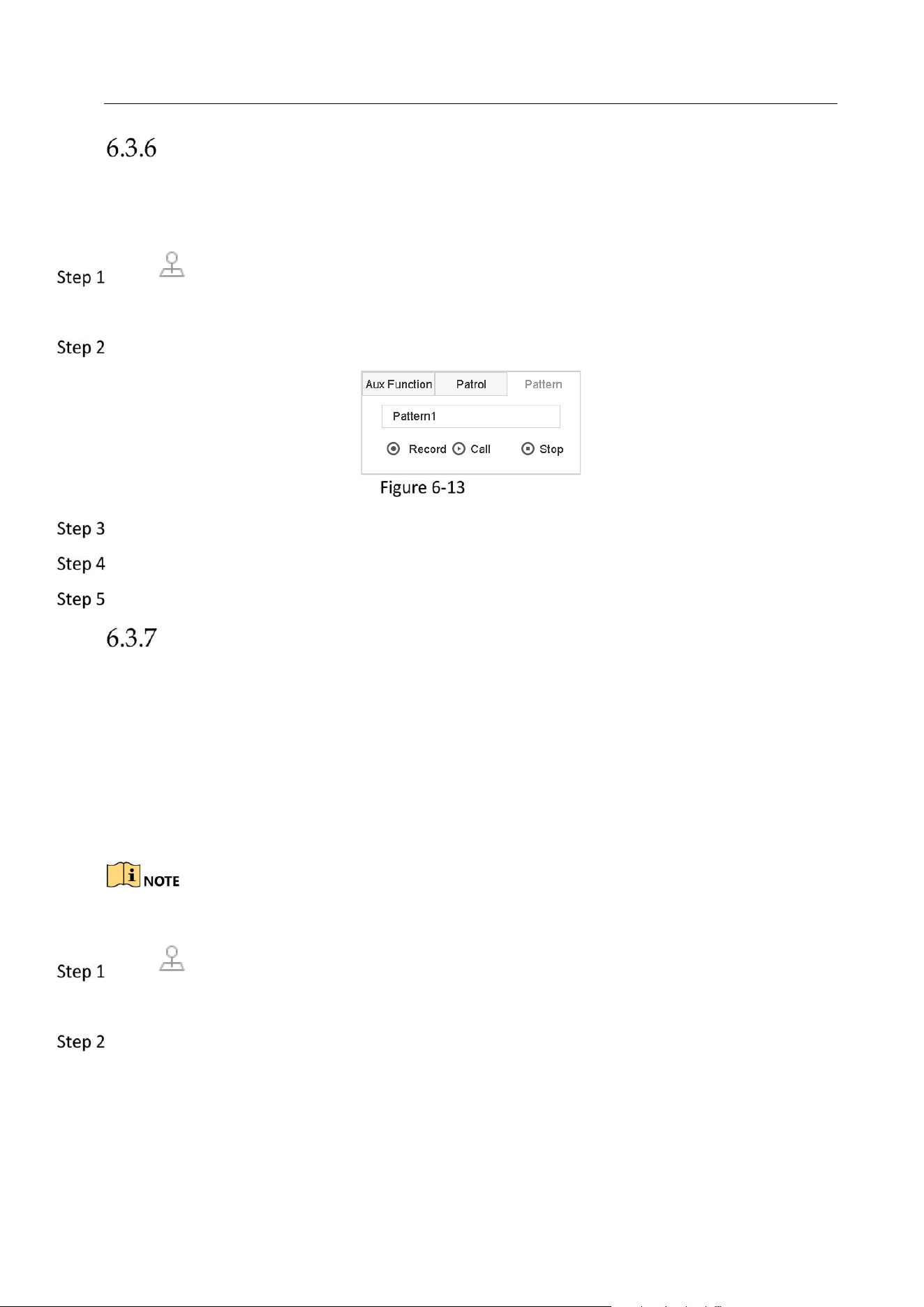
Network Video Recorder User Manual
60
Call a Pattern
Purpose:
Follow the procedure to move the PTZ camera according to the predefined patterns.
Click on the quick settings toolbar of the PTZ camera live view.
The PTZ control panel displays on the right of the interface.
Click Pattern to configure pattern.
Pattern Configuration
Select a pattern in the text field.
Click Call to call it.
(Optional) Click Stop to stop calling it.
Set Linear Scan Limits
Before you start:
Please make sure the connected IP camera supports the PTZ function, and is properly
connected.
Purpose:
The linear scan can be enabled to trigger the scan in the horizontal direction in the predefined
range.
This function is supported by some certain models.
Click on the quick settings toolbar of the PTZ camera live view.
The PTZ control panel displays on the right of the interface.
Click the directional buttons to wheel the camera to the location where you want to set the
limit, and click Left Limit or Right Limit to link the location to the corresponding limit.
Network Video Recorder User Manual
61
The speed dome starts linear scan from the left limit to the right limit, and you must set the left
limit on the left side of the right limit, as well the angle from the left limit to the right limit should
be no more than 180º.
Call Linear Scan
Before operating this function, make sure the connected camera supports the linear scan and is in
HIKVISION protocol.
Purpose:
Follow the procedure to call the linear scan in the predefined scan range.
Click on the quick settings toolbar of the PTZ camera live view.
The PTZ control panel displays on the right of the interface.
Click Linear Scan to start the linear scan and click it again to stop it.
(Optional) Click Restore to clear the defined left limit and right limit data.
Reboot the camera to take the settings into effect.
One-touch Park
Before operating this function, make sure the connected camera supports the linear scan and is in
HIKVISION protocol.
Purpose
For some certain model of the speed dome, it can be configured to start a predefined park
action (scan, preset, patrol and etc.) automatically after a period of inactivity (park time).
Click on the quick settings toolbar of the PTZ camera live view.
The PTZ control panel displays on the right of the interface.
Click Park (Quick Patrol), Park (Patrol 1) or Park (Preset 1) to activate the park action.
Park (Quick Patrol): The dome starts patrol from the predefined preset 1 to preset 32 in
order after the park time. The undefined preset will be skipped.
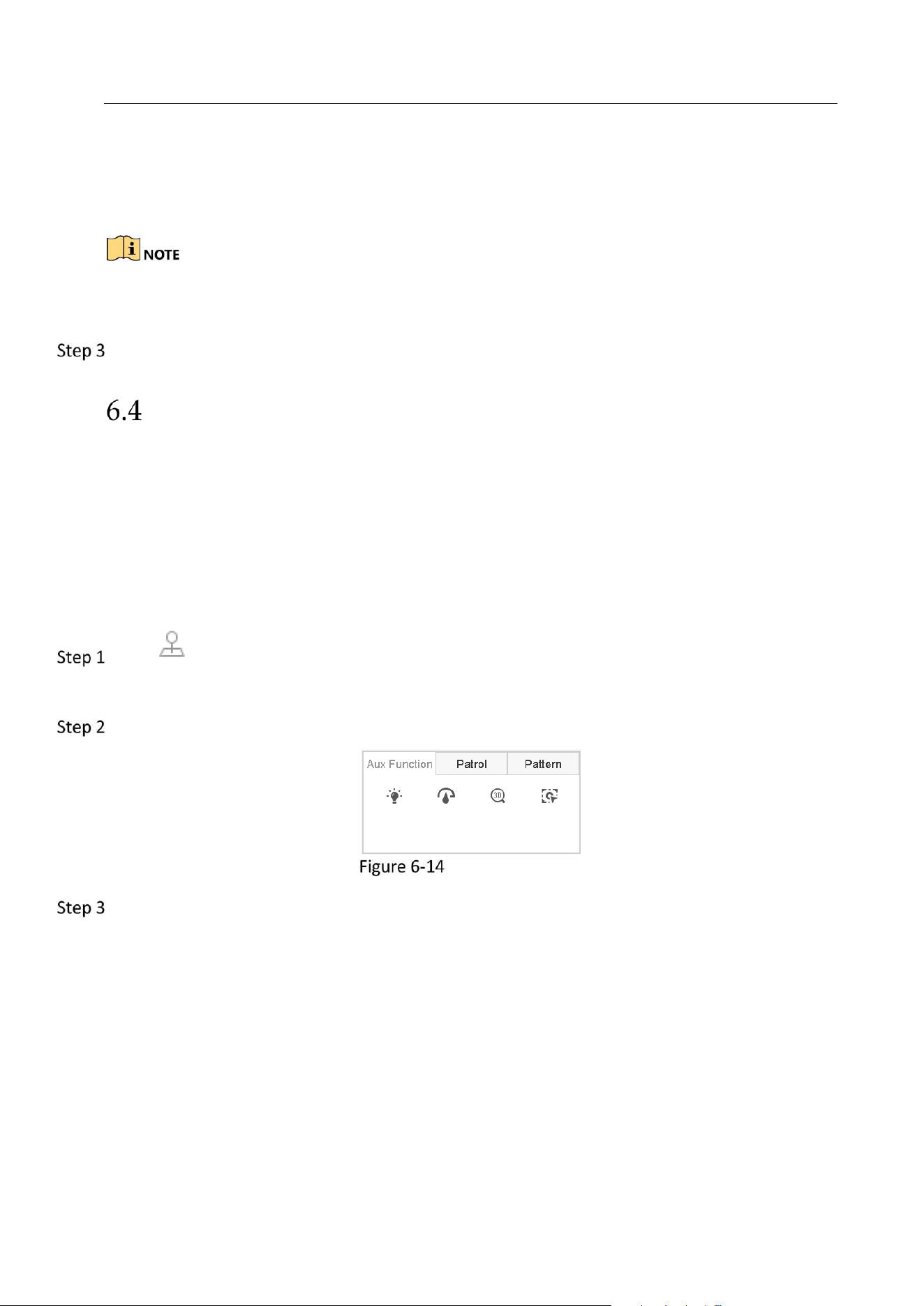
Network Video Recorder User Manual
62
Park (Patrol 1): The dome starts moving according to the predefined patrol 1 path after the
park time.
Park (Preset 1): The dome moves to the predefined preset 1 location after the park time.
The park time can only be set via the speed dome configuration interface. The value is 5s by
default.
Click Stop Park (Quick Patrol), Stop Park (Patrol 1) or Stop Park (Preset 1) to inactivate it.
Auxiliary Functions
Before you start
Please make sure the connected IP camera supports the PTZ function, and is properly
connected.
Purpose
You can operate the auxiliary functions including light, wiper, 3D positioning, and center on the
PTZ control panel.
Click on the quick settings toolbar of the PTZ camera live view.
The PTZ control panel displays on the right of the interface.
Click Aux Function.
Aux Function Configuration
Click the icons to operate the aux functions. See the table for the description of the icons.
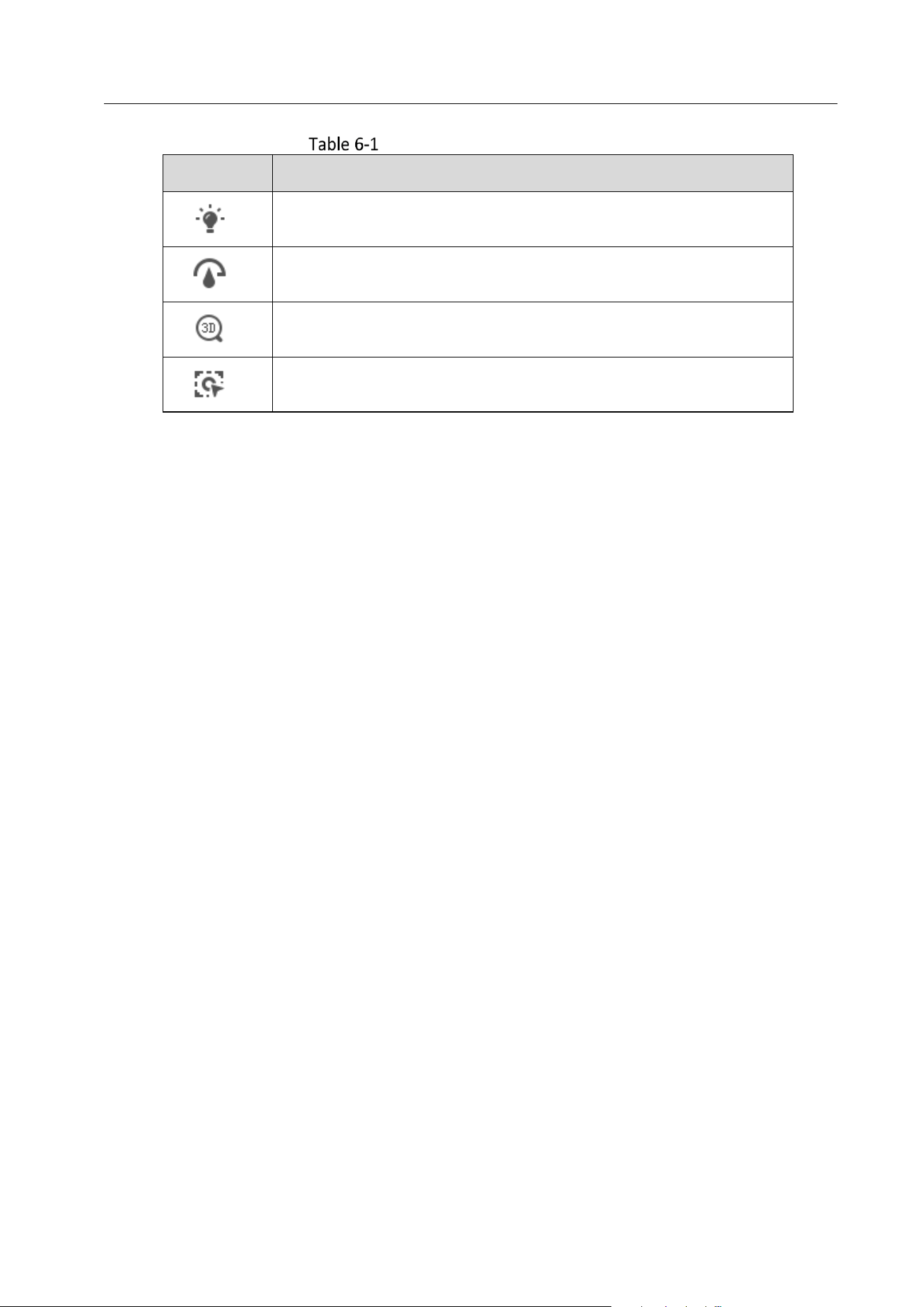
Network Video Recorder User Manual
63
Description of Aux Functions Icons
Icon
Description
Light on/off
Wiper on/off
3D positioning
Center
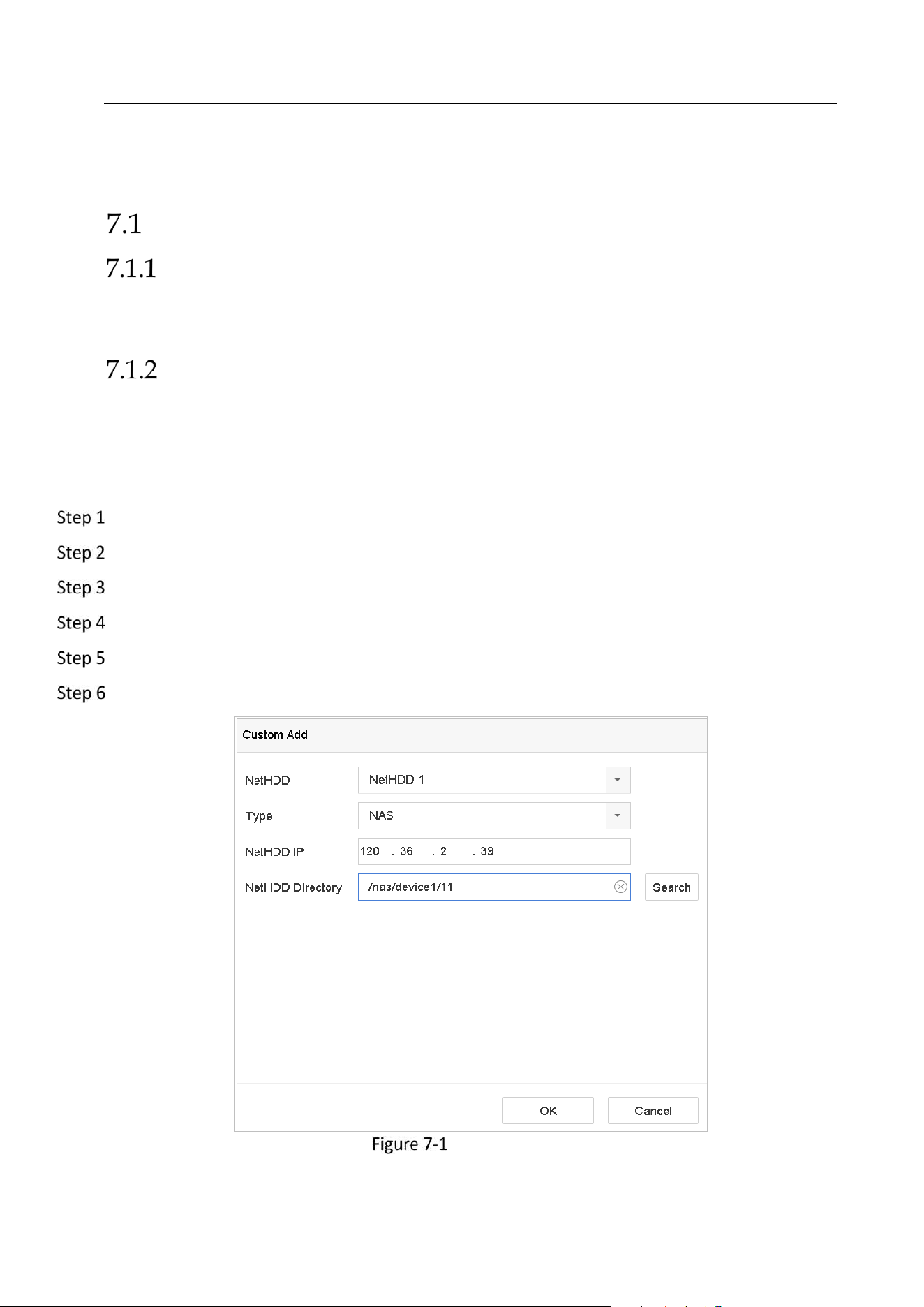
Network Video Recorder User Manual
64
Chapter 7 Storage
Storage Device Management
Install the HDD
Before startup of the device, install and connect the HDD to the device. Refer to the Quick Start
Guide for the installation instructions.
Add the Network Disk
You can add the allocated NAS or disk of IP SAN to device, and use it as network HDD. Up to 8
network disks can be added.
Adding NAS
Go to Storage > Storage Device.
Click Add to enter the Custom Add interface.
Select the NetHDD from the drop-down list.
Select the type to NAS.
Enter the NetHDD IP address in the text field.
Click Search to search the available NAS disks.
Add NAS Disk
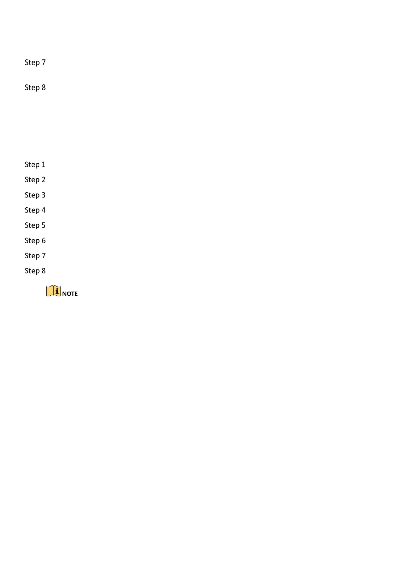
Network Video Recorder User Manual
65
Select the NAS disk from the list shown below, or you can manually enter the directory in the
text field of NetHDD Directory.
Click the OK to complete the adding of the NAS disk.
Result:
After having successfully added the NAS disk, return to the HDD Information menu. The added
NetHDD will be displayed in the list.
Adding IP SAN
Go to Storage > Storage Device.
Click Add to enter the Custom Add interface.
Select the NetHDD from the drop-down list.
Select the type to IP SAN.
Enter the NetHDD IP address in the text field.
Click Search to search the available IP SAN disks.
Select the IP SAN disk from the list shown below.
Click OK to complete the adding of the IP SAN disk.
Up to 1 IP SAN disk can be added.
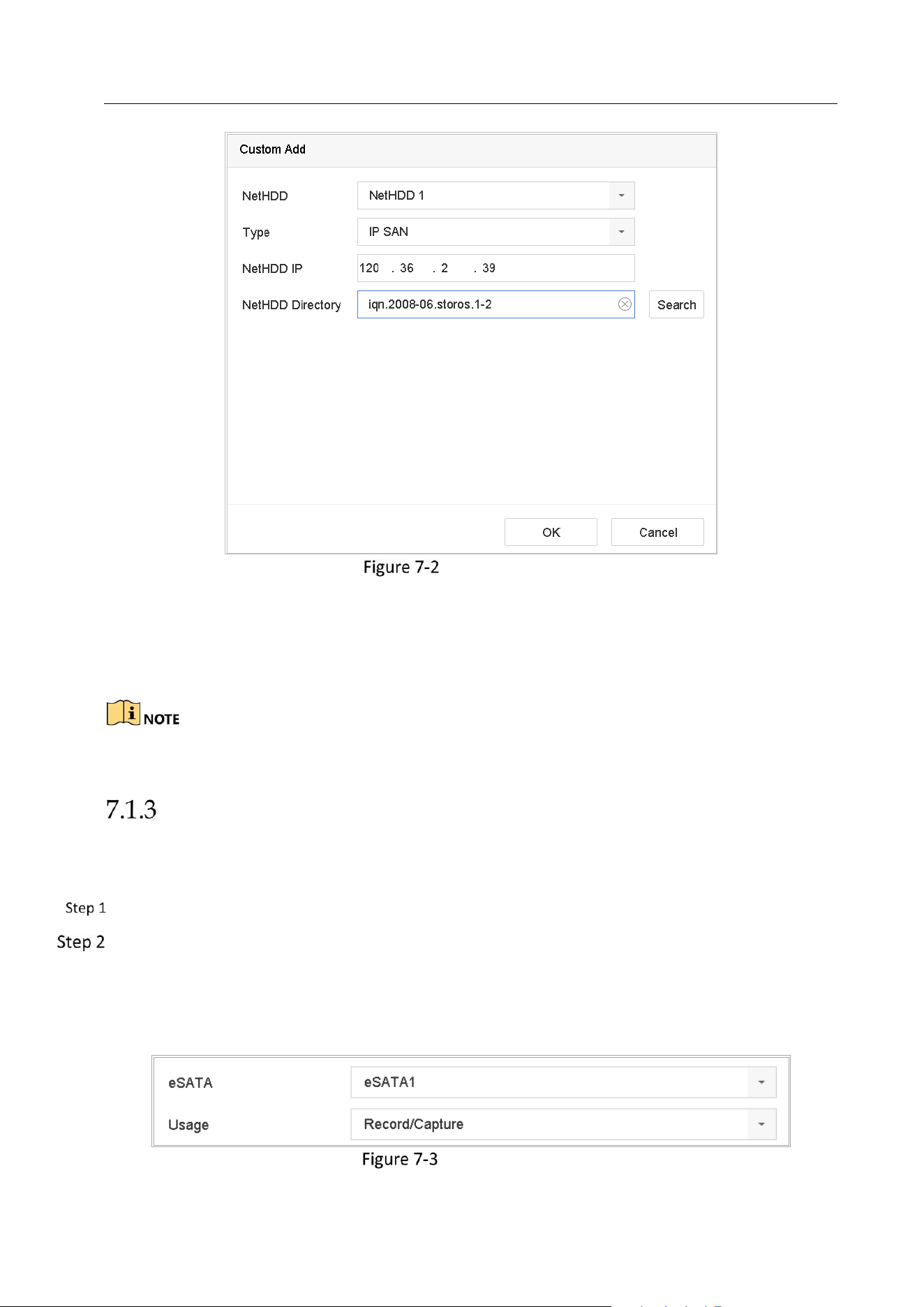
Network Video Recorder User Manual
66
Add IP SAN Disk
Result:
After having successfully added the IP SAN disk, return to the HDD Information menu. The added
NetHDD will be displayed in the list.
If the installed HDD or NetHDD is uninitialized, please select it and click the Init button for
initialization.
Configure eSATA for Data Storage
When there is an external eSATA device connected to device, you can configure eSATA for the
data storage, and you can manage the eSATA in the device.
Click Storage>Advanced.
Select the eSATA type to Export or Record/Capture from the dropdown list of eSATA.
Export: use the eSATA for backup.
Record/Capture: use the eSATA for record/capture. Refer to the following steps for operating
instructions.
Set eSATA Mode
Network Video Recorder User Manual
67
When the eSATA type is selected to Record/Capture, enter the storage device interface.
Edit the property of the selected eSATA, or initialize it is required.
Configure eSATA for Auto Backup
After you set an auto backup plan, the system will back up the local record files to eSATA. It will
back up the record files 24 hours ahead of the backup start time.
Before you start
Ensure the device has correctly connected with an external eSATA hard drive, and its usage type
is set as Export. Refer to 7.1.3 Configure eSATA for Data Storage for details.
Go to Storage > Auto Backup.
Check Auto Backup.
Set the backup start time in Start Backup at.
If the day experiences a failed backup, the device will back up the record files 48 hours ahead of
the backup start time in the next day.
Select channel(s) for backup.
Select Backup Stream Type as you desired.
Select overwrite type.
Disable: When hard drive is full, it will stop writing.
Enable: When hard drive is full, it will continue to write new files by deleting the oldest files.
Click Apply to finish.
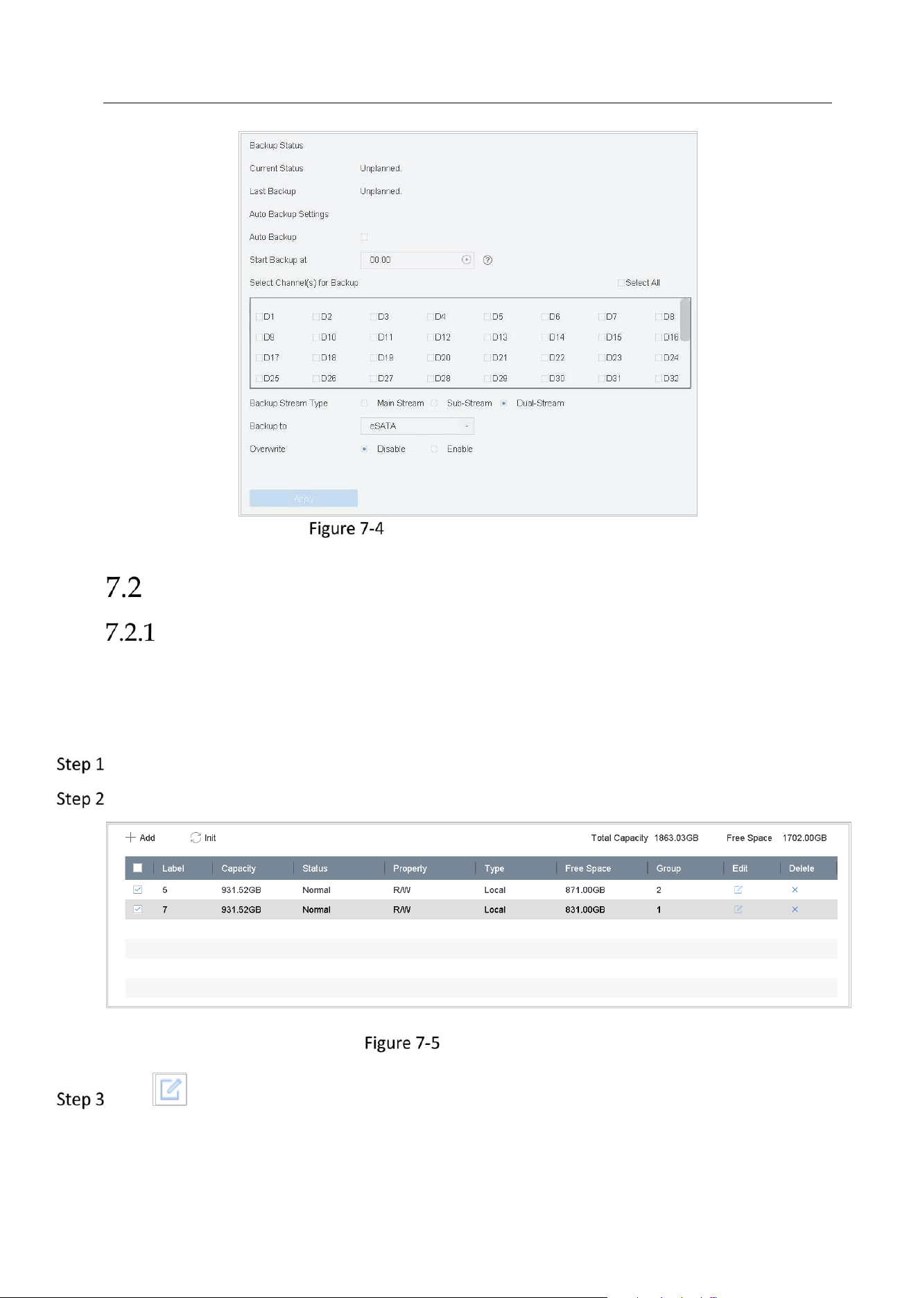
Network Video Recorder User Manual
68
Configure eSATA for Auto Backup
Storage Mode
Configure HDD Group
Purpose:
Multiple HDDs can be managed in groups. Video from specified channels can be recorded onto a
particular HDD group through HDD settings.
Go to Storage> Storage Device.
Check the checkbox to select the HDD to set the group.
Storage Device
Click to enter the Local HDD Settings interface.
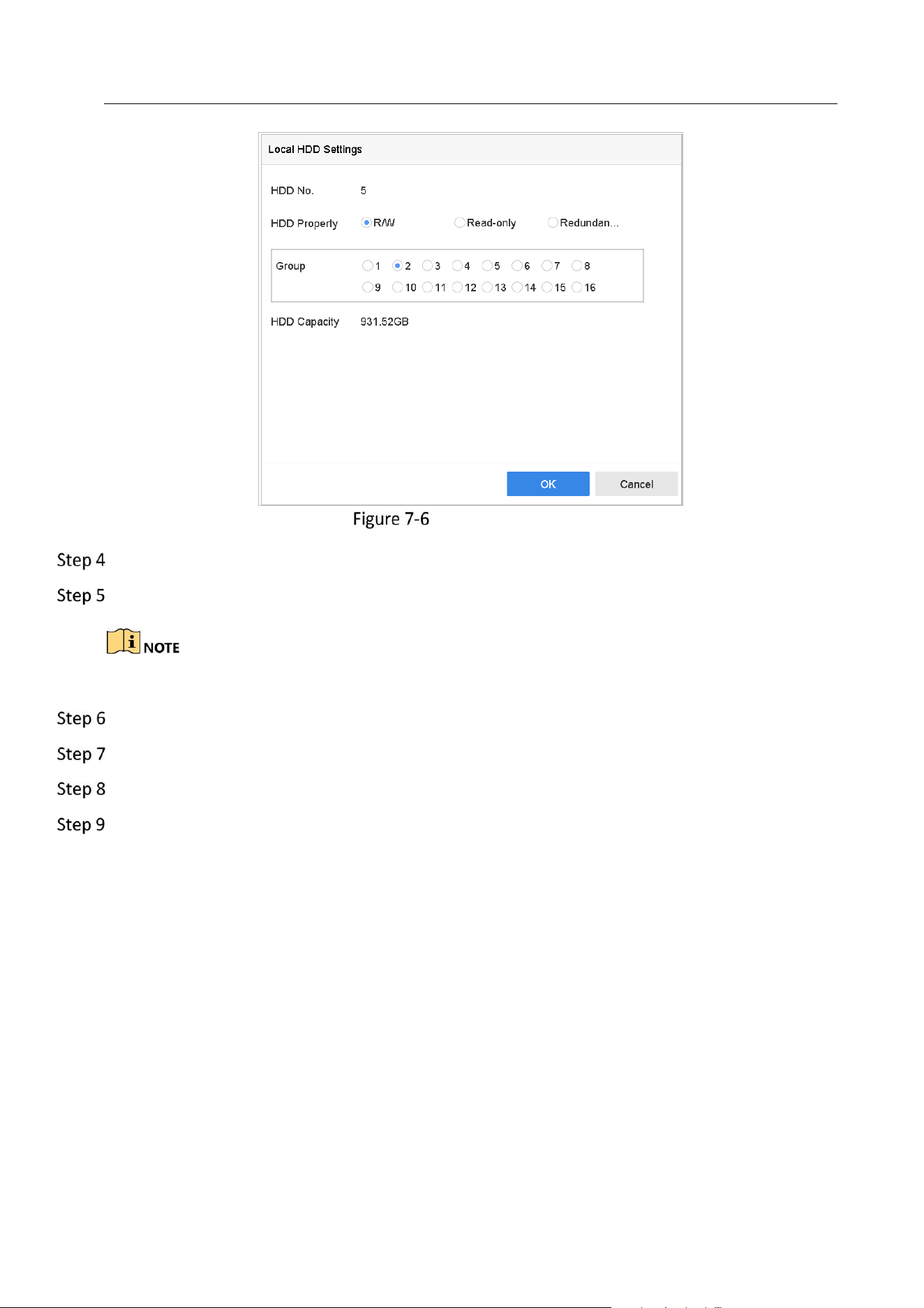
Network Video Recorder User Manual
69
Local HDD Settings
Select the Group number for the current HDD.
Click OK.
Regroup the cameras for HDD if the HDD group number is changed.
Go to Storage> Storage Mode.
Check the checkbox of Group tab.
Select the group No. from the list.
Check the checkbox to select the IP camera (s) to record/capture on the HDD group.
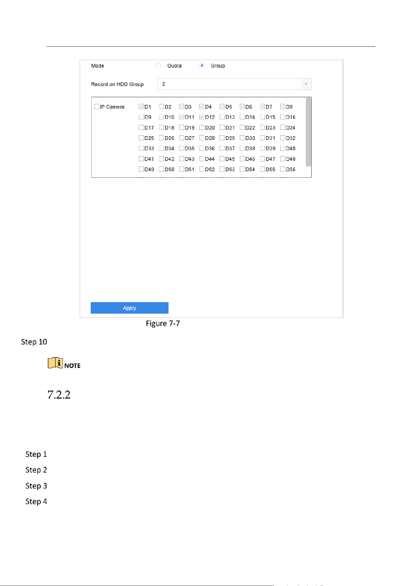
Network Video Recorder User Manual
70
Storage Mode-HDD Group
Click Apply.
Reboot the device to activate the new storage mode settings.
Configure HDD Quota
Purpose:
Each camera can be configured with allocated quota for the storage of recorded files or captured
pictures.
Go to Storage > Storage Mode.
Check the checkbox of Quota tab.
Select a camera to set quota.
Enter the storage capacity in the text fields of Max. Record Capacity (GB) and Max. Picture
Capacity (GB).
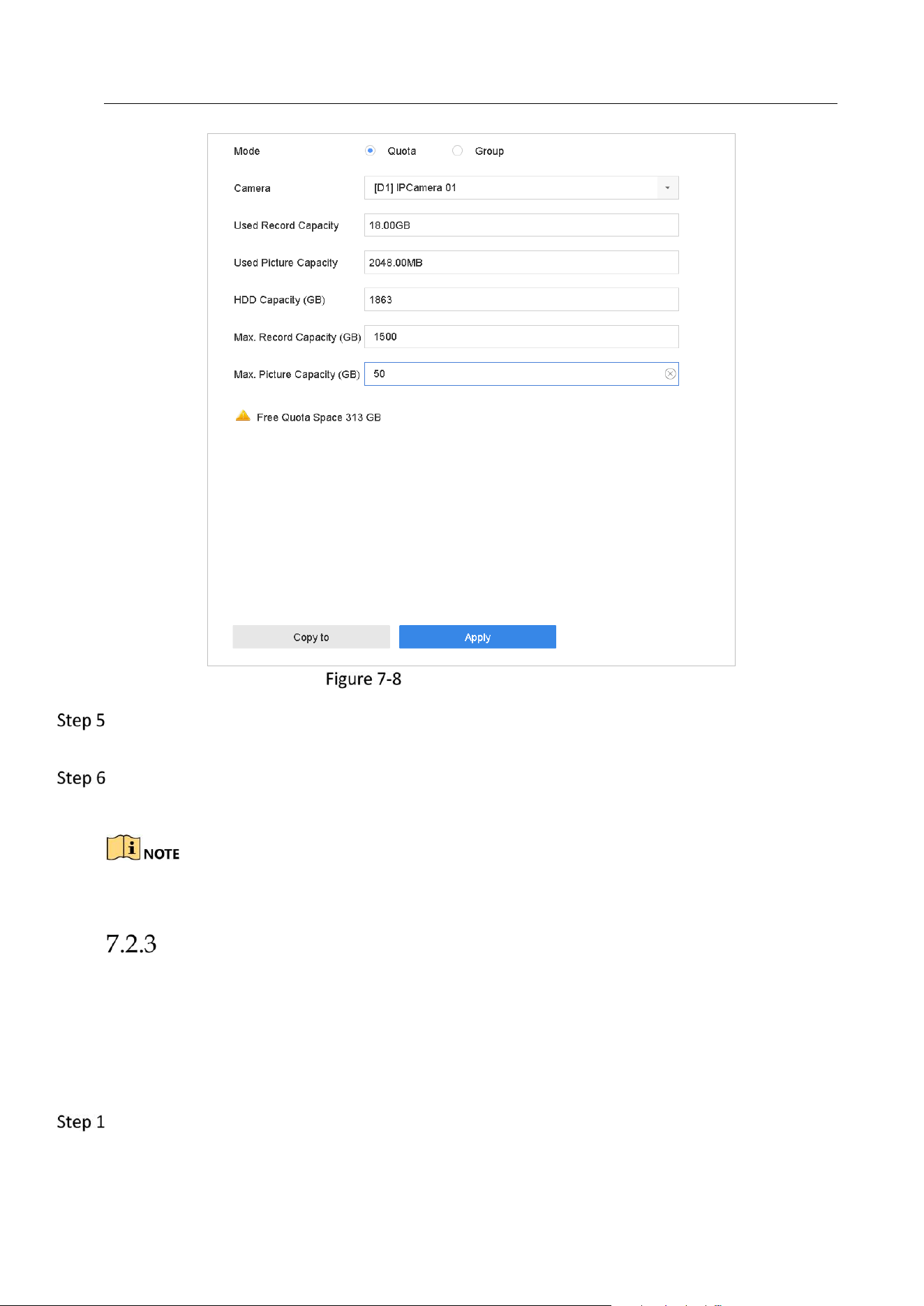
Network Video Recorder User Manual
71
Storage Mode-HDD Quota
(Optional) You can click Copy to if you want to copy the quota settings of the current camera to
other cameras.
Click the Apply button to apply the settings. Reboot the device to activate the new storage
mode settings.
When the quota capacity is set to 0, all cameras will use the total capacity of HDD for record and
picture capture.
Configure Data Release
Purpose:
Enable smart release function and set the quota ratio between the normal video and important
video. After these, the device immigrates the important video from the normal video quota to
the quota of important video. The device will automatically delete the expired videos. The
function greatly improves the utility rate of space without consuming R/W performance.
Go to Storage > Storage Mode.
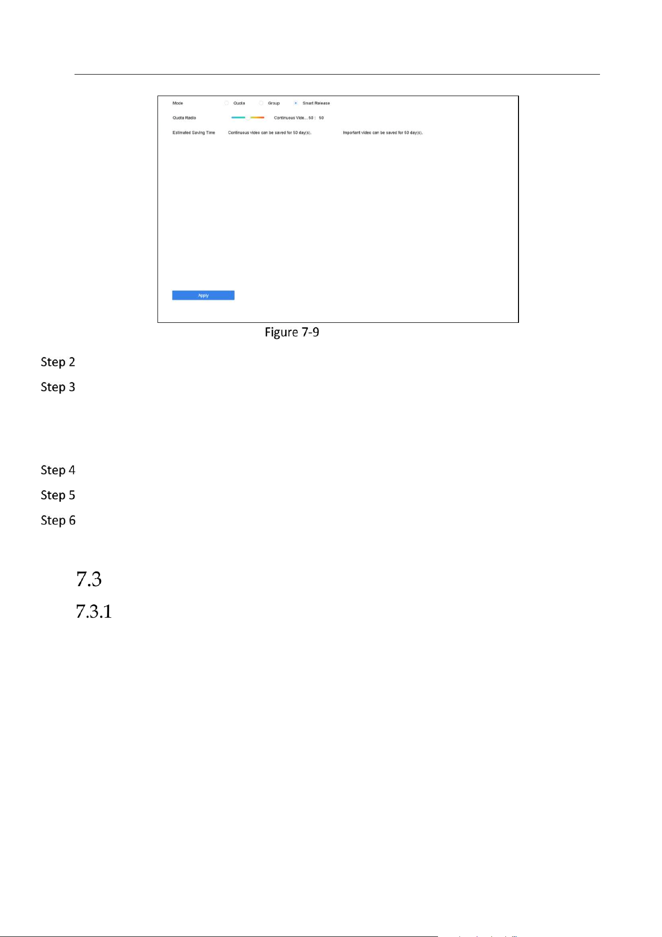
Network Video Recorder User Manual
72
Storage Mode
Select Mode as Smart Release.
Adjust the Quota Ratio between the normal video and important video. You can view the
Estimated Saving Time for the continuous video and import video.
Estimated Saving Time: Calculated based on the quota ratio, storage capacity, and video size
of last week. Expired continuous videos will be deleted. The time updates every minute.
Click Apply.
Click Yes on popup message dialog to reboot device.
Optionally, go to Maintenance > System Info > Smart Release Status to view release status for
each channel.
Recording Parameters
Main Stream
The Main Stream refers to the primary stream that affects data recorded to the hard disk drive
and will directly determine your recording quality and image size.
Comparing with the sub-stream, the main stream can provide a higher quality video with higher
resolution and frame rate.
Frame Rate (FPS - Frames Per Second): refers to how many frames are captured each second. A
higher frame rate is advantageous when there is movement in the video stream, as it maintains
image quality throughout.
Resolution: Image resolution is a measure of how much detail a digital image can hold: the greater
the resolution, the greater the level of detail. Resolution can be specified as the number of pixel-
columns (width) by the number of pixel-rows (height), e.g.,1024×768.

Network Video Recorder User Manual
73
Bitrate: The bit rate (in kbit/s or Mbit/s) is often referred to as speed, but actually defines the
number of bits/time unit and not distance/time unit.
Enable H.264+ Mode: The H.264+ mode helps to ensure the high video quality with a lowered
bitrate. It can effectively reduces the need of bandwith and HDD storage space.
A higher resolution, frame rate and bitrate setting will provide you the better video quality, but it
will also require more internet bandwidth and use more storage space on the hard disk drive.
Sub-Stream
The sub-stream is a second codec that runs alongside the mainstream. It allows you to reduce
the outgoing internet bandwidth without sacrificing your direct recording quality.
The sub-stream is often exclusively used by smartphone applications to view live video. Users
with limited internet speeds may benefit most from this setting.
Picture
The picture refers to the live picture capture in continuous or event recording type.
Picture Quality: set the picture quality to low, medium or high. The higher picture quality results
in more storage space requirement.
Interval: the interval of capturing live picture.
Capture Delay Time: the duration of capturing pictures.
ANR
ANR (Automatic Network Replenishment) function which enables the IP camera to save the
recording files in the local storage when the network is disconnected, and when the network is
resumed, it uploads the files to the device.
Enable the ANR (Automatic Network Replenishment) function via the web browser
(Configuration > Storage > Schedule Settings > Advanced).
Configure Advanced Recording Settings
Go to Storage > Schedule Settings > Record Schedule/Capture Schedule.
Check the checkbox of Enable to enable scheduled recording.
Click Advanced to set the recording parameters.
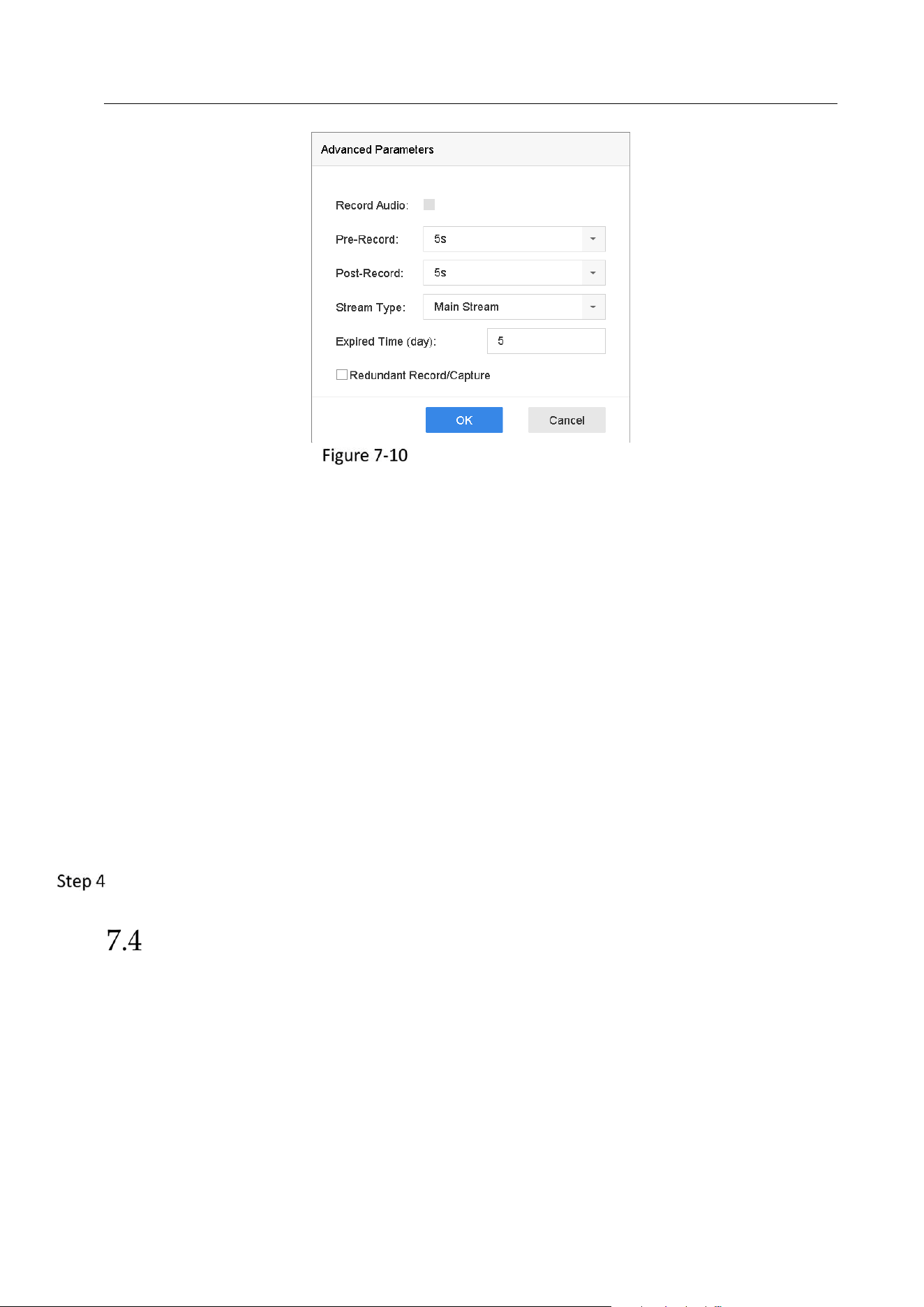
Network Video Recorder User Manual
74
Advanced Record Settings
Record Audio: Check the checkbox to enable or disable audio recording.
Pre-record: The time you set to record before the scheduled time or event. For example, when
an alarm triggers the recording at 10:00, and if you set the pre-record time as 5 seconds, the
camera records at 9:59:55.
Post-record: The time you set to record after the event or the scheduled time. For example,
when an alarm triggered recording ends at 11:00, and if you set the post-record time as 5
seconds, it records till 11:00:05.
Expired Time: The expired time is period for a recorded file to be kept in the HDD. When the
deadline is reached, the file will be deleted. If you set the expired time to 0, the file will not be
deleted. The actual keeping time for the file should be determined by the capacity of the HDD.
Redundant Record/Capture: By enabling redundant record or capture you save the record and
captured picture in the redundant HDD. See Chapter Configure Redundant Recording and
Capture.
Stream Type: Main stream and sub-stream are selectable for recording. When you select sub-
stream, you can record for a longer time with the same storage space.
Click OK to save the settings.
Configure Recording Schedule
Set the record schedule, and then the camera automatically starts/stops recording according to
the configured schedule.
Before you start
Make sure you have installed the HDDs to the device or added the network disks before you
want to store the video files, pictures and log files.
Refer to the Quick Start Guide for the HDD installation.
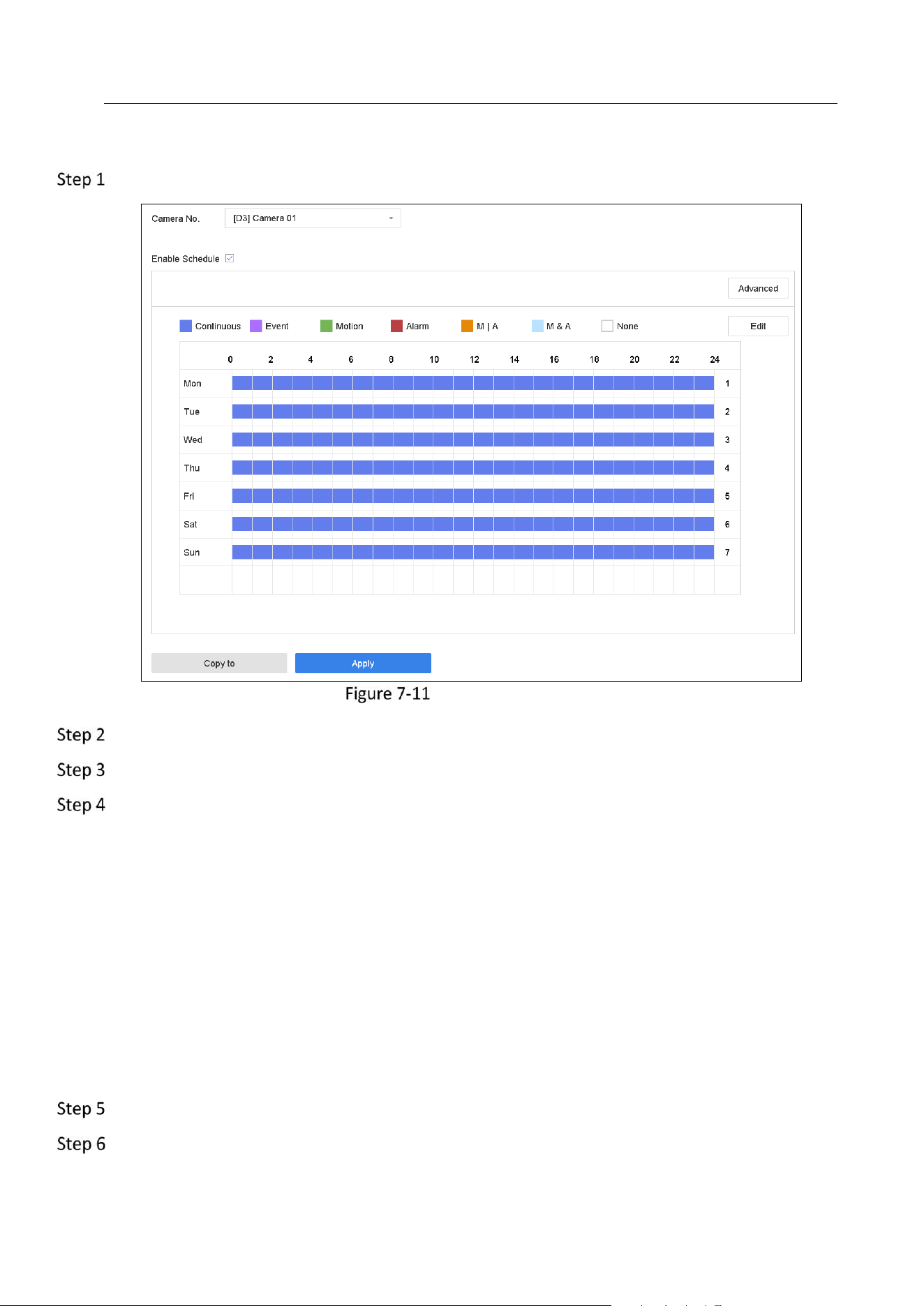
Network Video Recorder User Manual
75
Refer to Chapter 7.1.2 Add the Network Disk for network HDD connections.
Go to Storage > Recording Schedule.
Recording Schedule
Select a camera.
Check Enable Schedule.
Select a record type. The record type can be Continuous, Motion Detection, Alarm, Motion |
Alarm, Motion & Alarm, and Event.
Different recording types are configurable.
Continuous: scheduled recording.
Event: recording triggered by all event triggered alarm.
Motion: recording triggered by motion detection.
Alarm: recording triggered by alarm.
M/A: recording triggered by either motion detection or alarm.
M&A: recording triggered by motion detection and alarm.
Select a day and click-and-drag the mouse on the time bar to set the record schedule.
Repeat the above steps to schedule recording or capture for other days in the week.

Network Video Recorder User Manual
76
The all-day continuous recording is configured for the device by factory default.
Click Apply to save the settings.
To enable Motion, Alarm, M | A (motion or alarm), M & A (motion and alarm) and Event triggered
recording and capture, you must configure the motion detection settings, alarm input settings and
other events as well. Please refer to Chapter 10 and Chapter 12 for details.
Configure Continuous Recording
Go to Camera > Encoding Parameters > Recording Parameters.
Set the continuous main stream/sub-stream recording parameters for the camera.
Go to Storage > Recording Schedule.
Select the recording type to Continuous.
Drag the mouse on the time bar to set the continuous recording schedule. Refer to Chapter 7.4
Configure Recording Schedule for details.
Configure Motion Detection Triggered Recording
You can configure the recording triggered by the motion detection event.
Go to System > Event > Normal Event > Motion Detection.
Configure the motion detection and select the channel (s) to trigger the recording when motion
event occurs. Refer to Chapter 11.4 Configure Motion Detection Alarm for details.
Go to Camera > Encoding Parameters > Recording Parameters.
Set the event main stream/sub-stream recording parameters for the camera.
Go to Storage > Recording Schedule.
Select the recording type to Motion.
Drag the mouse on the time bar to set the motion detection recording schedule. Refer to
Chapter 7.4 Configure Recording Schedule for details.
Configure Event Triggered Recording
You can configure the recording triggered by the motion detection, motion detection and alarm,
face detection, vehicle detection, line crossing detection, etc.

Network Video Recorder User Manual
77
Go to System > Event.
Configure the event detection and select the channel (s) to trigger the recording when event
occurs. Refer to Chapter 10 and Chapter 12 VCA Event Alarm for details.
Go to Camera > Encoding Parameters > Recording Parameters.
Set the event main stream/sub-stream recording parameters for the camera.
Go to Storage > Recording Schedule.
Select the recording type to Event.
Drag the mouse on the time bar to set the event detection recording schedule. Refer to Chapter
7.4 Configure Recording Schedule for details.
Configure Alarm Triggered Recording
You can configure the recording triggered by the motion detection, face detection, vehicle
detection, line crossing detection, etc.
Go to System > Event > Normal Event > Alarm Input.
Configure the alarm input and select the channel (s) to trigger the recording when alarm occurs.
Refer to Chapter 10 and Chapter 12 VCA Event Alarm for details.
Go to Camera > Encoding Parameters > Recording Parameters.
Set the event main stream/sub-stream recording parameters for the camera.
Go to Storage > Recording Schedule.
Select the recording type to Alarm
Drag the mouse on the time bar to set the alarm recording schedule. Refer to Chapter 7.4
Configure Recording Schedule for details.
Configure Picture Capture
The picture refers to the live picture capture in continuous or event recording type.
Go to Storage > Capture Schedule > Advanced.
Set the picture parameters.
Resolution: set the resolution of the picture to capture.
Picture Quality: set the picture quality to low, medium or high. The higher picture quality
results in more storage space requirement.
Interval: the interval of capturing live picture.
Capture Delay Time: the duration of capturing pictures.
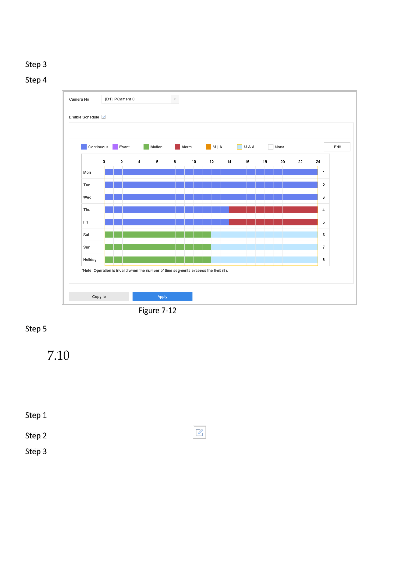
Network Video Recorder User Manual
78
Go to Storage > Capture Schedule.
Select the camera to configure the picture capture.
Set Picture Capture Schedule
Set the picture capture schedule. Refer to Chapter 7.4 Configure Recording Schedule for details.
Configure Holiday Recording and Capture
Purpose:
Follow the steps to configure the record or capture schedule on holiday for that year. You may
want to have different plan for recording and capture on holiday.
Go to System > Holiday Settings.
Select a holiday item from the list and click .
Check the Enable to configure the holiday.
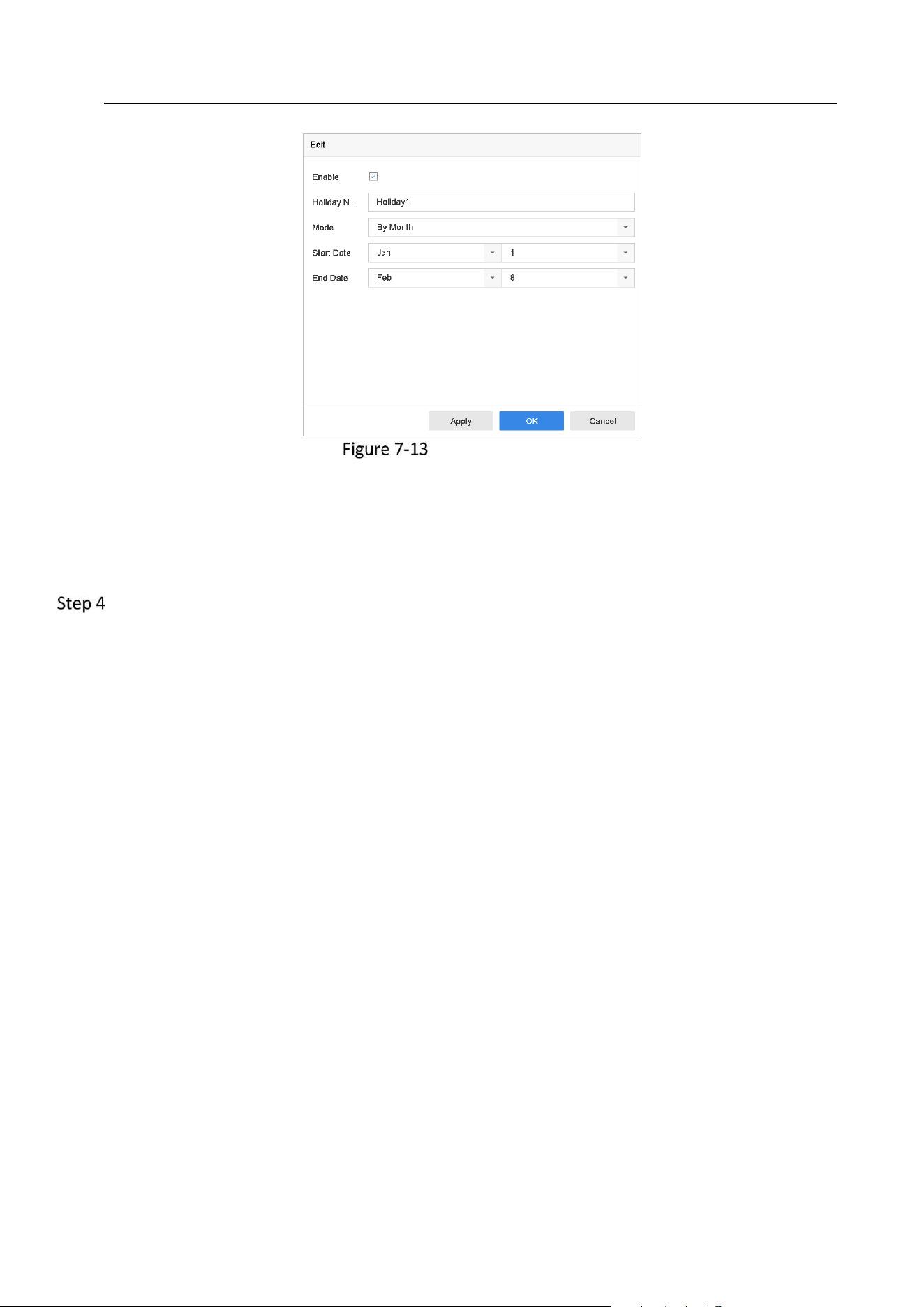
Network Video Recorder User Manual
79
Edit Holiday Settings
1) Edit the holiday name.
2) Select the mode to by date, by week or by month.
3) Set the start and end date of the holiday.
4) Click OK.
Set the schedule for the holiday recording. Refer to Chapter 7.4 Configure Recording Schedule
for details.
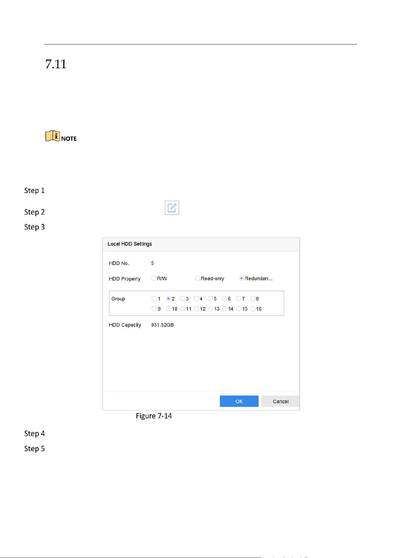
Network Video Recorder User Manual
80
Configure Redundant Recording and Capture
Purpose:
Enabling redundant recording and capture, which means saving the record files and captured
pictures not only in the R/W HDD but also in the redundant HDD, will effectively enhance the
data safety and reliability. .
You must set the storage mode to Group before you set the HDD property to Redundancy. For
detailed information, please refer to Chapter 7.2.1 Configure HDD Group. There should be at least
another HDD which is in Read/Write status.
Go to Storage > Storage Device.
Select a HDD from the list and Click to enter the Local HDD Settings interface.
Set the HDD property to Redundancy.
HDD Property-Redundancy
Go to Storage > Schedule Settings > Record Schedule/Capture Schedule.
Click Advanced to set the camera recording parameters.
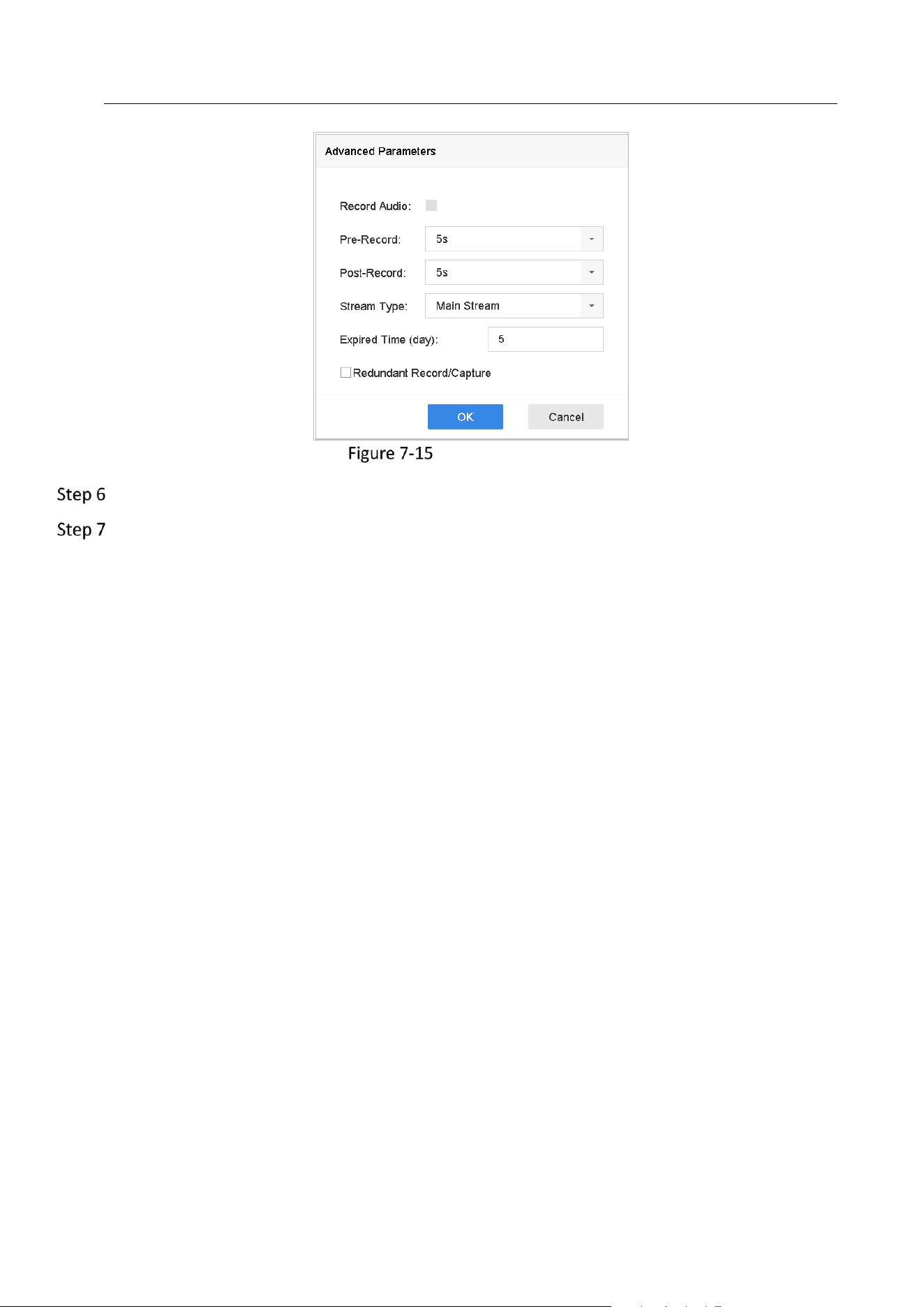
Network Video Recorder User Manual
81
Record Parameters
Check the checkbox of Redundant Record/Capture.
Click OK to save settings.
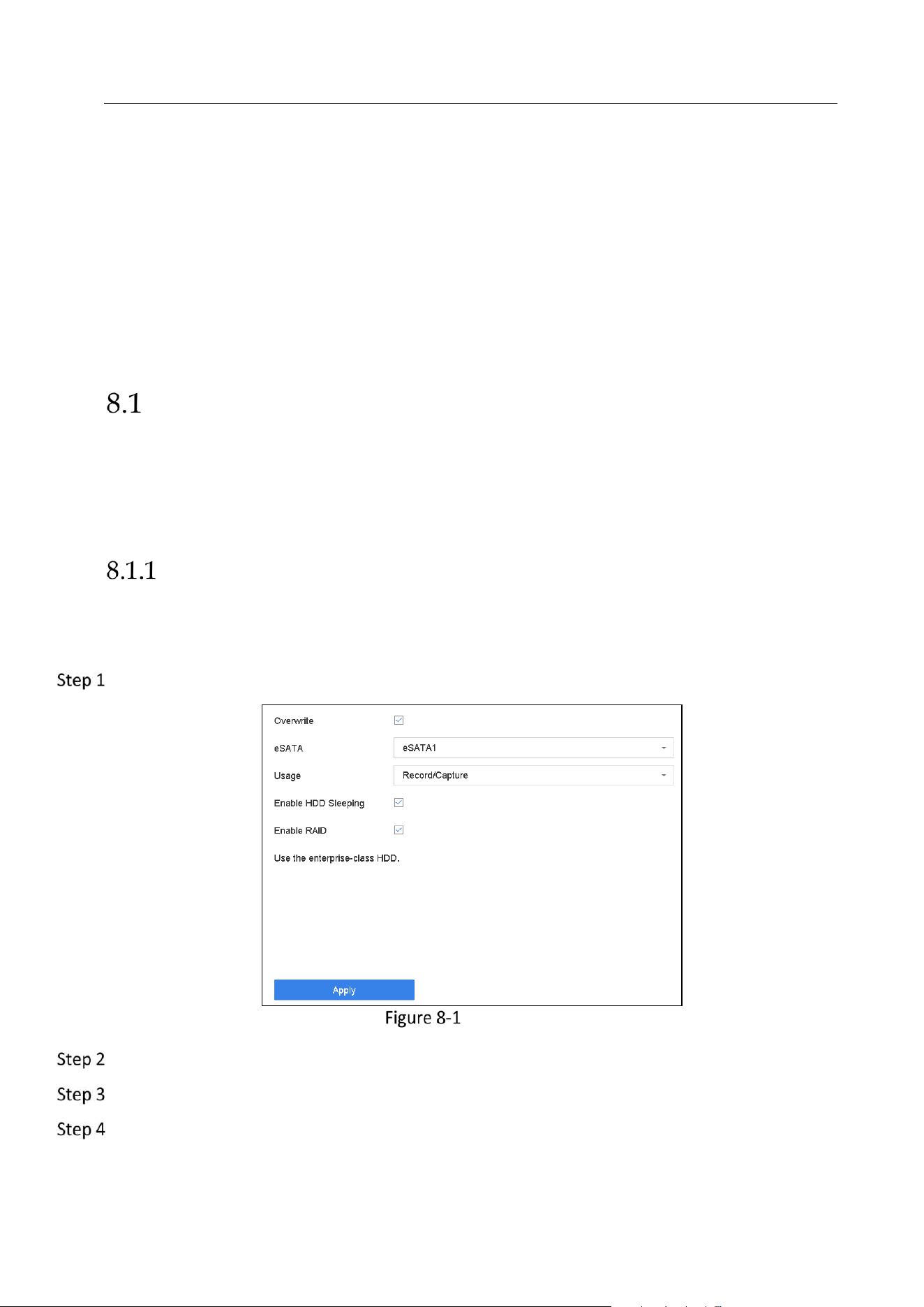
Network Video Recorder User Manual
82
Chapter 8 Disk Array
Purpose:
Disk array is a data storage virtualization technology that combines multiple physical disk drive
components into a single logical unit. An array stores data over multiple HDDs to provide
enough redundancy so that data can be recovered if one disk fails. Data is distributed across the
drives in one of several ways called "RAID levels", depending on what level of redundancy and
performance is required.
Create Disk Array
Purpose:
The device supports the disk array that is realized by software. You can enable the RAID function
as required. Two ways are available for creating array: one-touch configuration and manual
configuration. The following flow chart shows the process of creating array.
Enable RAID
Purpose:
Perform the following steps to enable the disk array function.
Go to Storage > Advanced.
Advanced
Check Enable RAID.
Click Apply.
Reboot device to take effect the settings.
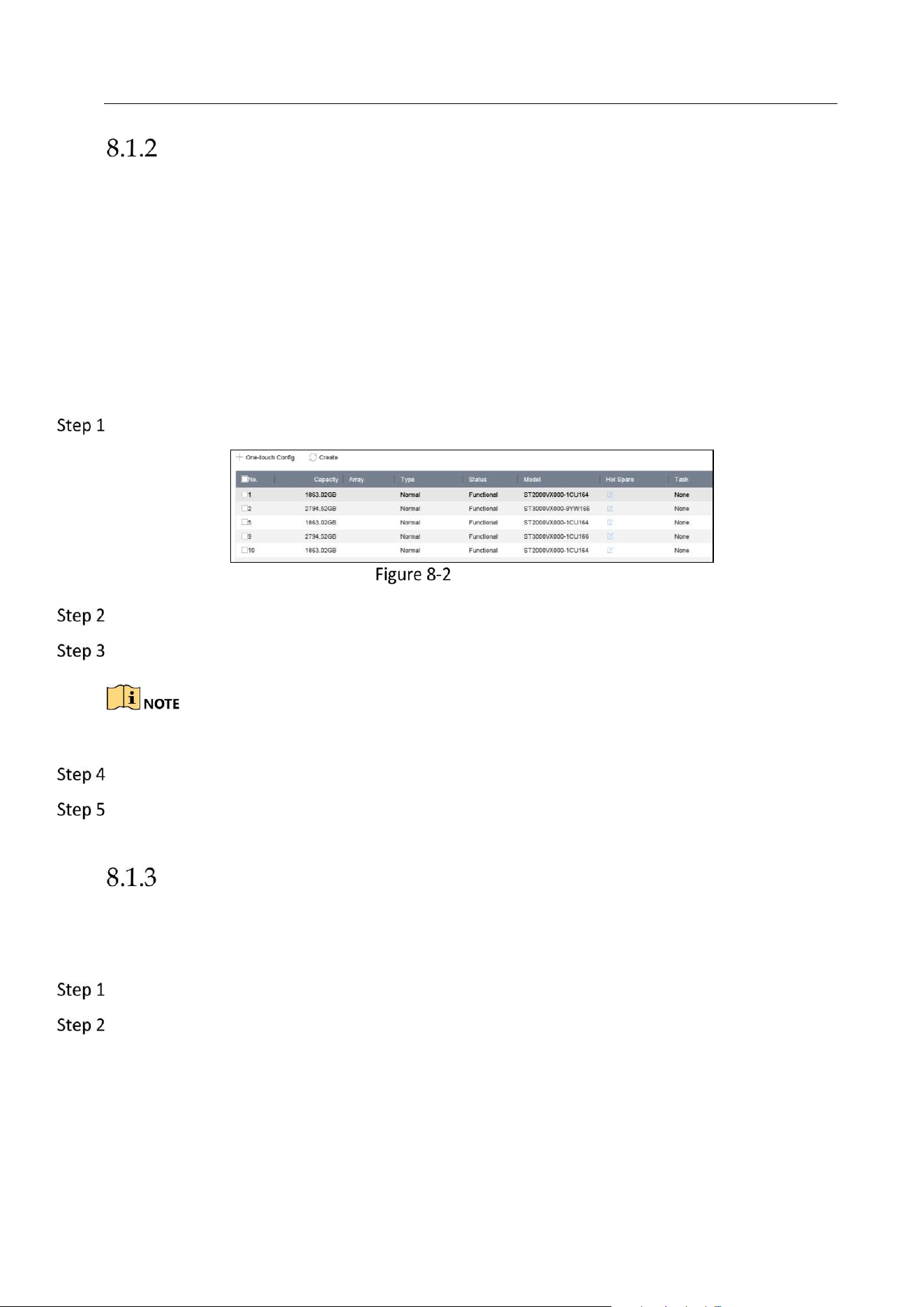
Network Video Recorder User Manual
83
One-Touch Creation
Purpose:
One-touch configuration helps you to quickly create the disk array. By default, the array type
created by one-touch configuration is RAID 5.
Before you start:
Enable RAID function. For details, refer to Chapter 8.1.1 Enable RAID.
Install at least 3 HDDs. If more than 10 HDDs are installed, 2 arrays will be created. To maintain
reliable and stable running of the HDDs, it is recommended to use enterprise-level HDDs with
the same model and capacity.
Go to Storage > RAID Setup > Physical Disk.
Physical Disk
Click One-touch Config.
Edit the array name in Array Name text filed and click OK to start configuring.
If you install 4 HDDs or more, a hot spare disk for array rebuilding will be created.
A message box will pop up when the array creation is completed, click OK on it.
Optionally, the device will automatically initialize the created array. Go to Storage > RAID
Setup > Array view the information of created arrray.
Manual Creation
Purpose:
Manually create the array of RAID 0, RAID 1, RAID 5, RAID 6, and RAID 10.
Go to Storage > RAID Setup > Physical Disk.
Click Create.
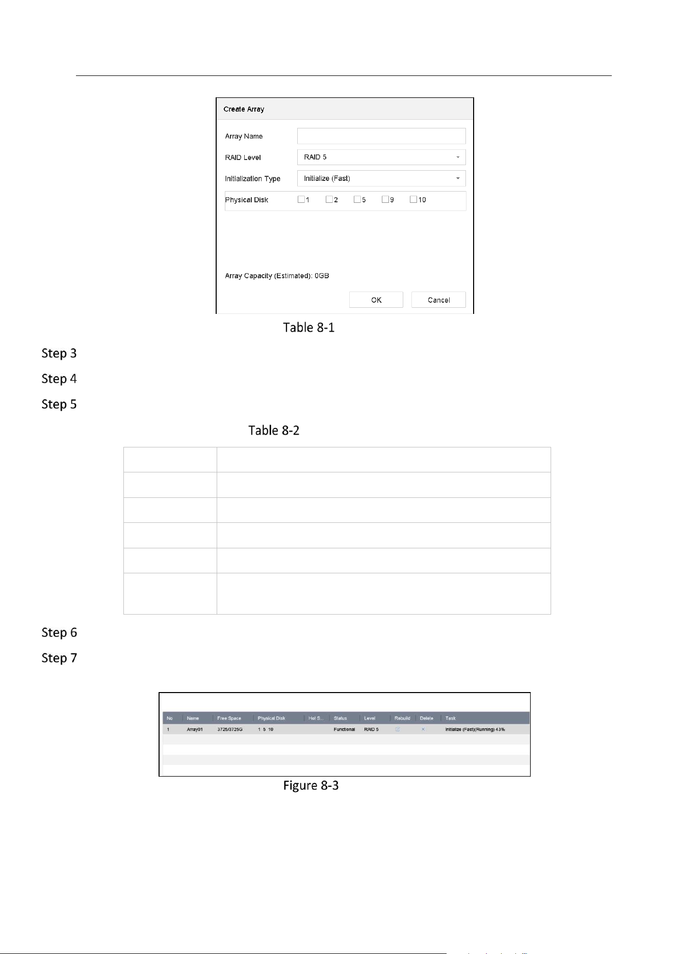
Network Video Recorder User Manual
84
Create Array
Enter the array name.
Select RAID Level as RAID 0, RAID 1, RAID 5, RAID 6, or RAID 10 as required.
Select the physical disks to constitute array.
Required Number of HDD
RAID Level
Required Number of HDD
RAID 0
At least 2 HDDs.
RAID 1
At least 2 HDDs.
RAID 5
At least 3 HDDs.
RAID 6
At least 4 HDDs.
RAID 10
The number of HDD must be an even ranges from 4 to
16.
Click OK.
Optionally, the device will automatically initialize the created array. Go to Storage > RAID
Setup > Array view the information of created arrray.
Array List
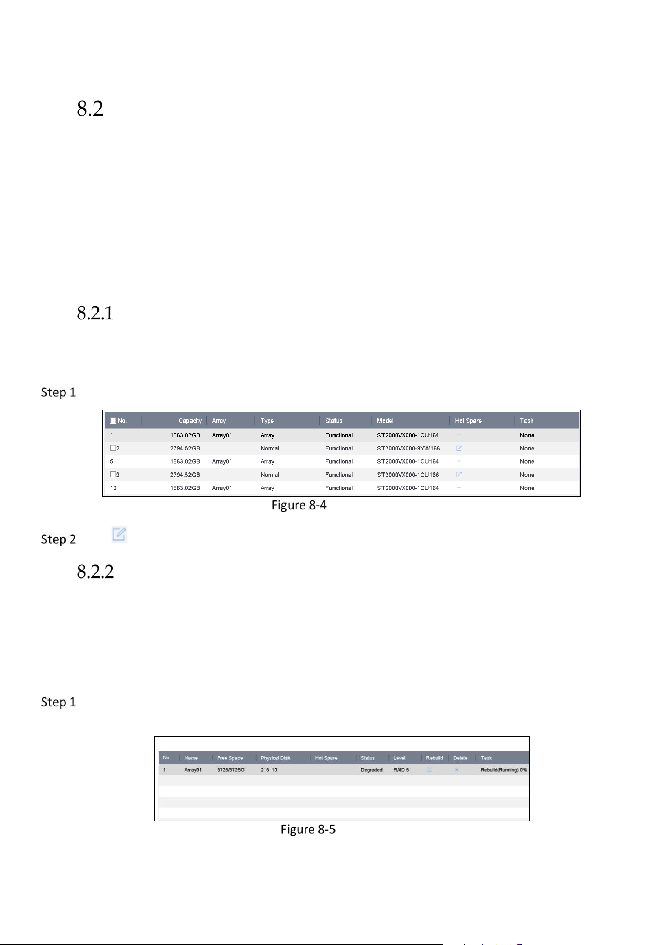
Network Video Recorder User Manual
85
Rebuild Array
Purpose:
The status of array includes Functional, Degraded and Offline. To ensure the high security and
reliability of the data stored in array, you should take immediate and proper maintenance at
arrays according their status.
Functional: No disk loss in the array.
Offline: The number of lost disks has exceeded the limit.
Degraded: If amount of HDD fail in array, array degrades. You should recover it to Functional by
array rebuilding.
Configure Hot Spare Disk
Purpose:
Hot spare disks are required for disk array automatic rebuilding.
Go to Storage > RAID Setup > Physical Disk.
Physical Disk
Click of an available HDD to set it as the hot spare disk.
Automatically Rebuild Array
Purpose:
The device can automatically rebuild degraded arrays with the hot spare disks.
Before you start:
Create hot spare disks. For details, refer to Chapter 8.2.1 Configure Hot Spare Disk.
The device will automatically rebuild the degraded arrays with the hot spare disks. Go to
Storage > RAID Setup > Array to view rebuilding progress.
Array List
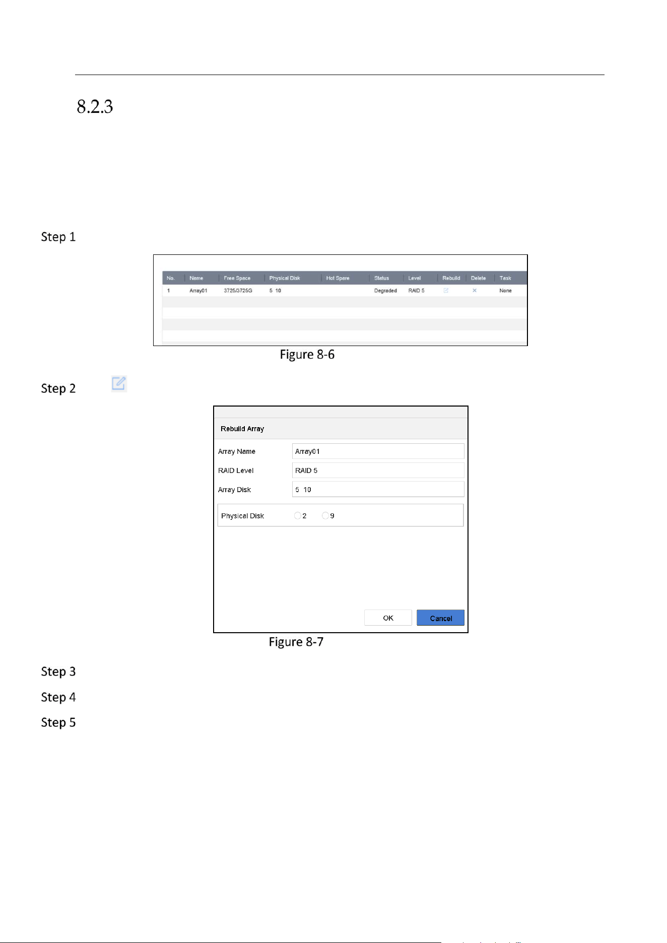
Network Video Recorder User Manual
86
Manually Rebuild Array
Purpose:
If no hot spare disks are configured, rebuild the degraded array manually.
Before you start:
At least one available physical disk should exist for rebuilding the array.
Go to Storage > RAID Setup > Array.
Array List
Click of degraded array.
Rebuild Array
Select the available physical disk.
Click OK.
Click OK on the pop up message box “Do not unplug the physical disk when it is under
rebuilding”.
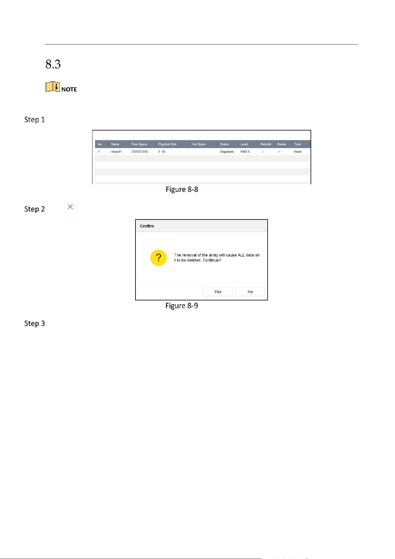
Network Video Recorder User Manual
87
Delete Array
Deleting array will delete all the data saved in it.
Go to Storage > RAID Setup > Array.
Array List
Click of array to delete.
Attention
Click Yes on the popup message box.
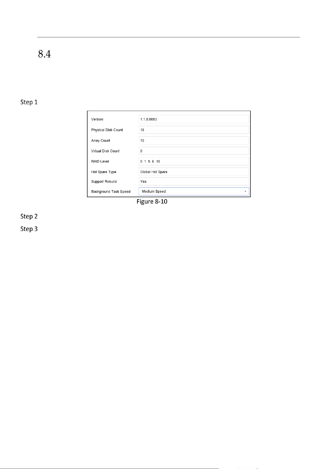
Network Video Recorder User Manual
88
Check and Edit Firmware
Purpose:
You can view the information of the firmware and set the background task speed on the
Firmware interface.
Go to Storage > RAID Setup > Firmware.
Firmware
Optionally, set the Background Task Speed.
Click Apply.
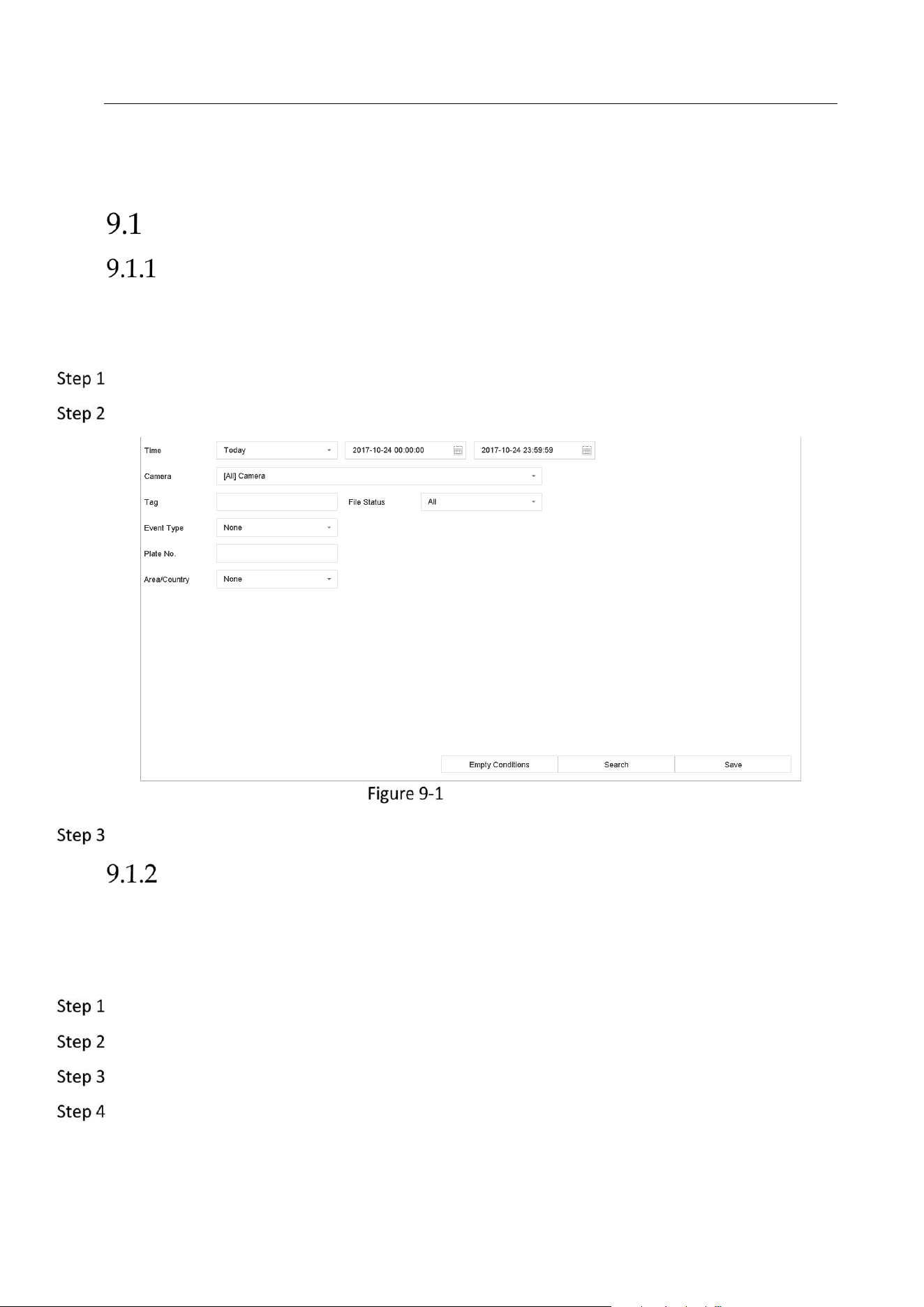
Network Video Recorder User Manual
89
Chapter 9 File Management
Search and Export All Files
Search Files
Purpose
Specify detailed conditions to search videos and pictures.
Go to File Management > All Files.
Specify detailed conditions, including time, camera, event type, etc.
Search All Files
Click Search to display results. The matched files will be displayed.
Export Files
Purpose
Export files for backup purposes using USB device (USB flash drive, USB HDD, USB optical disc
drive), SATA optical disc drive or eSATA HDD.
Search files to export. For details, see 9.1.1 Search Files.
Click to select files and click Export.
Select the file to export as Video and Log and click OK.
Click OK to export files to backup device.
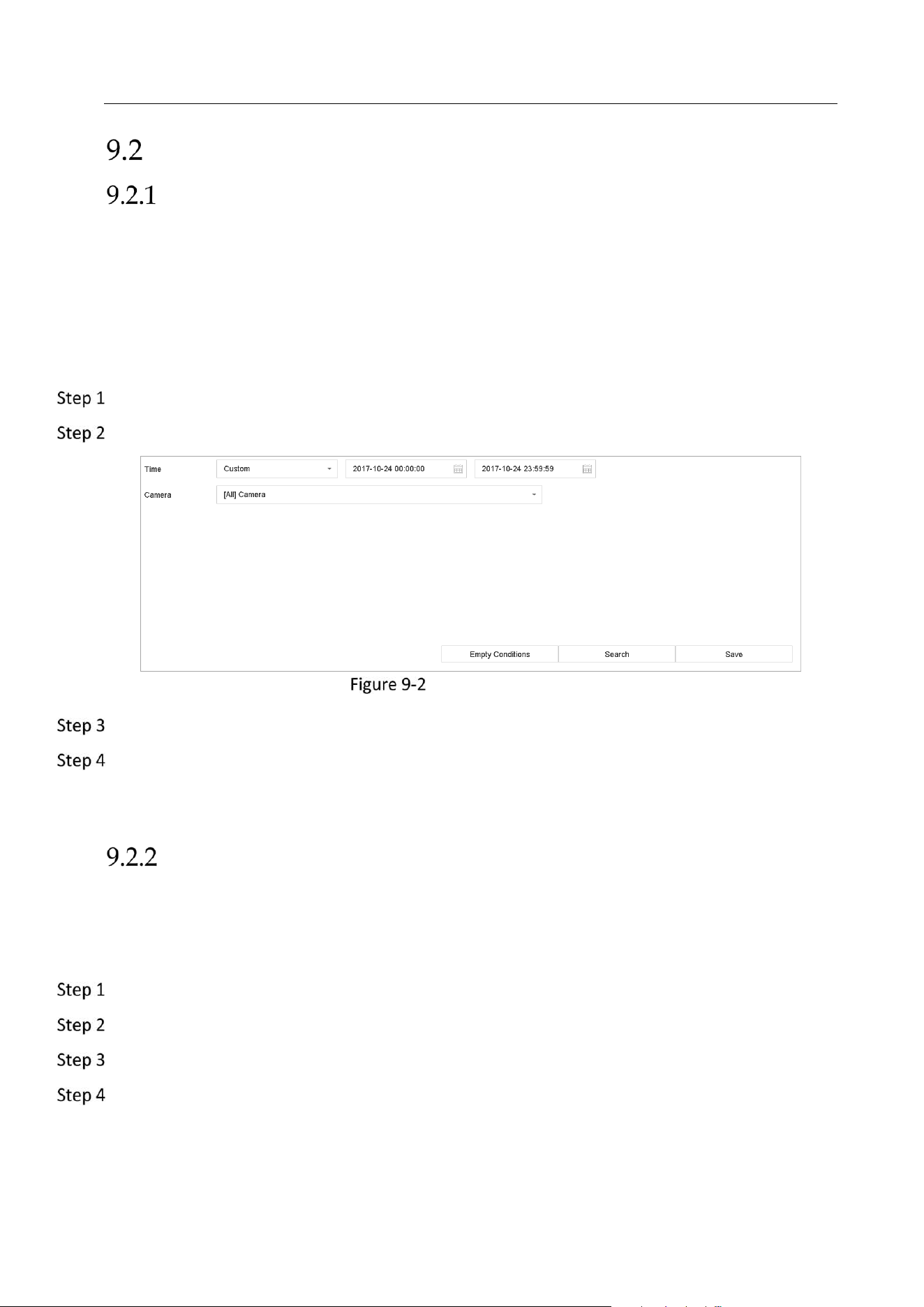
Network Video Recorder User Manual
90
Search and Export Human Files
Search Human Files
Purpose
Specify detailed conditions to search human pictures and videos.
Before you start
Configure human body detection function for the cameras you want to search and export
human pictures and videos.
Go to File Management > Human Files.
Select Time and Camera to search.
Search Human Files
Click Search to display results. The matched files are displayed in thumbnail or list.
Select Target Picture or Source Picture in menu bar to display related pictures only.
Target Picture: Display the search results of people close-up.
Source Picture: Display the search results of original picture captured by camera.
Export Human Files
Purpose
Export files for backup purposes using USB device (USB flash drive, USB HDD, USB optical disc
drive), SATA optical disc drive or eSATA HDD.
Search for the human files to export. For details, see 9.2.1 Search Human Files.
Click to select files and click Export.
Select the file to export as Video and Log and click OK.
Click OK to export files to backup device.
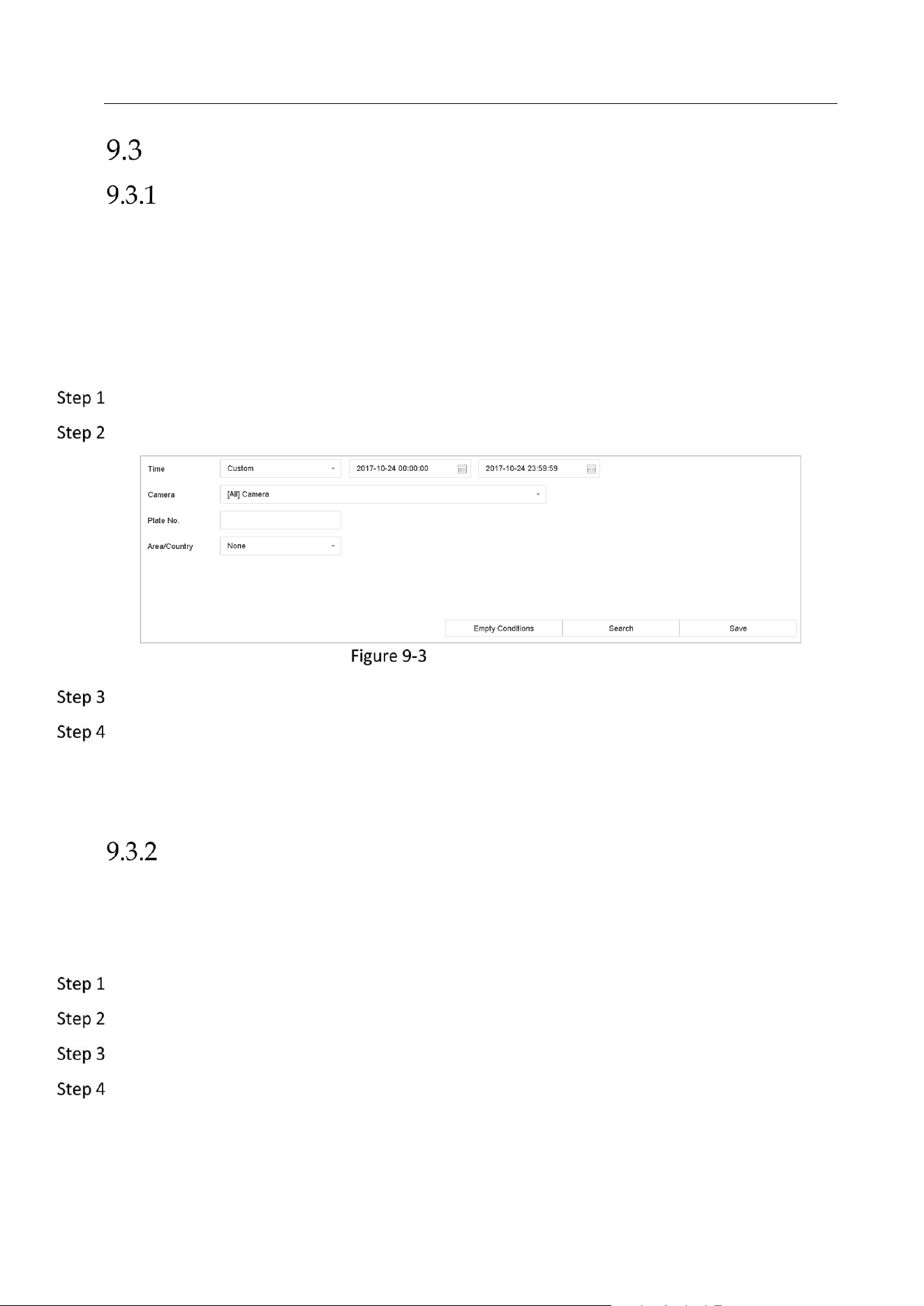
Network Video Recorder User Manual
91
Search and Export Vehicle Files
Search Vehicle Files
Purpose
Specify detailed conditions to search vehicle pictures and videos.
Before you start
Configure vehicle detection function for the cameras you want to search and export vehicle
pictures and videos.
Go to File Management > Vehicle Files.
Specify detailed conditions, including Time, Camera, Plate No., and Area/Country.
Search Vehicle Files
Click Search to display results. The matched files are displayed in thumbnail or list.
Select Target Picture or Source Picture in menu bar to display related pictures only. Select
Video or Picture to specify the file type.
Target Picture: Display the search results of vehicle close-up.
Source Picture: Display the search results of original picture captured by camera.
Export Vehicle Files
Purpose
Export files for backup purposes using USB device (USB flash drive, USB HDD, USB optical disc
drive), SATA optical disc drive or eSATA HDD.
Search for the vehicle files to export. For details, see 9.3.1 Search Vehicle Files.
Click to select files and click Export.
Select the file to export as Video and Log and click OK.
Click OK to export files to backup device.

Network Video Recorder User Manual
92
Search History Operation
Save Search Condition
Purpose
You can save the search conditions for future reference and quick search.
Go to File Management > All Files/People Appearance File/Vehicle File.
Set the search conditions.
Click Save.
Enter a name in text field and click Finished. The saved search conditions will be displayed in
search history list.
Call Search History
Purpose:
You can quickly search files by calling search history.
Go to File Management > All Files/Human Files/Vehicle Files.
Click a search conditon to quickly search files.
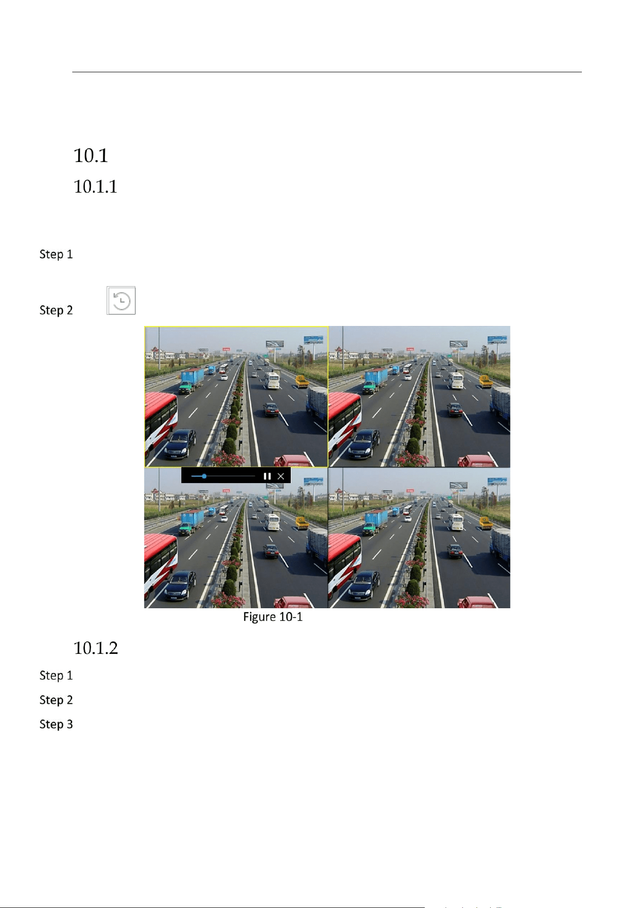
Network Video Recorder User Manual
93
Chapter 10 Playback
Play Video Files
Instant Playback
Instant Playback enables the device to play the recorded video files in last five minutes. If no
video is found, it means there is no recording during the last five minutes.
On the live view window of the selected camera, move the cursor to the window bottom to
access the toolbar.
Click to start instant playback.
Playback Interface
Play Normal Video
Go to Playback.
Check one or more cameras in the camera list to start playing the video.
Select a date in the calendar.
Use the toolbar in the bottom part of playback interface to control the playing and realize a
series of operations. Refer to Chapter 10.2 Playback Operations 8.2.
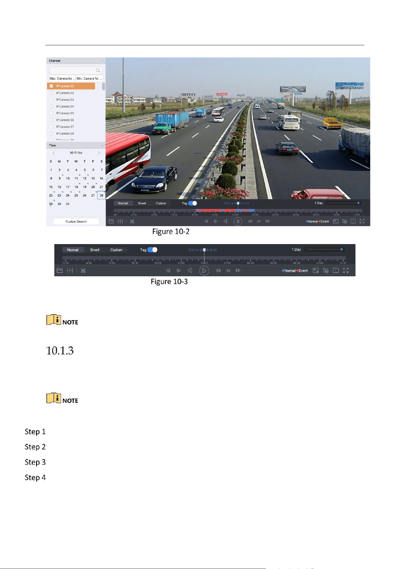
Network Video Recorder User Manual
94
Playback Interface
Toolbar of Playback
Click the channel(s) to execute simultaneous playback of multiple channels.
The playing speed of 256X is supported.
Play Smart Searched Video
In the smart playback mode, the device can analyze the video containing the motion, line or
intrusion detection information, mark it in red color and play the smart searched video.
The smart playback must be in the single-channel playing mode.
Go to Playback.
Start playing the video of camera.
Click Smart.
From the toolbar at the bottom of the playing window, click the motion/line crossing/ intrusion
icon for search.
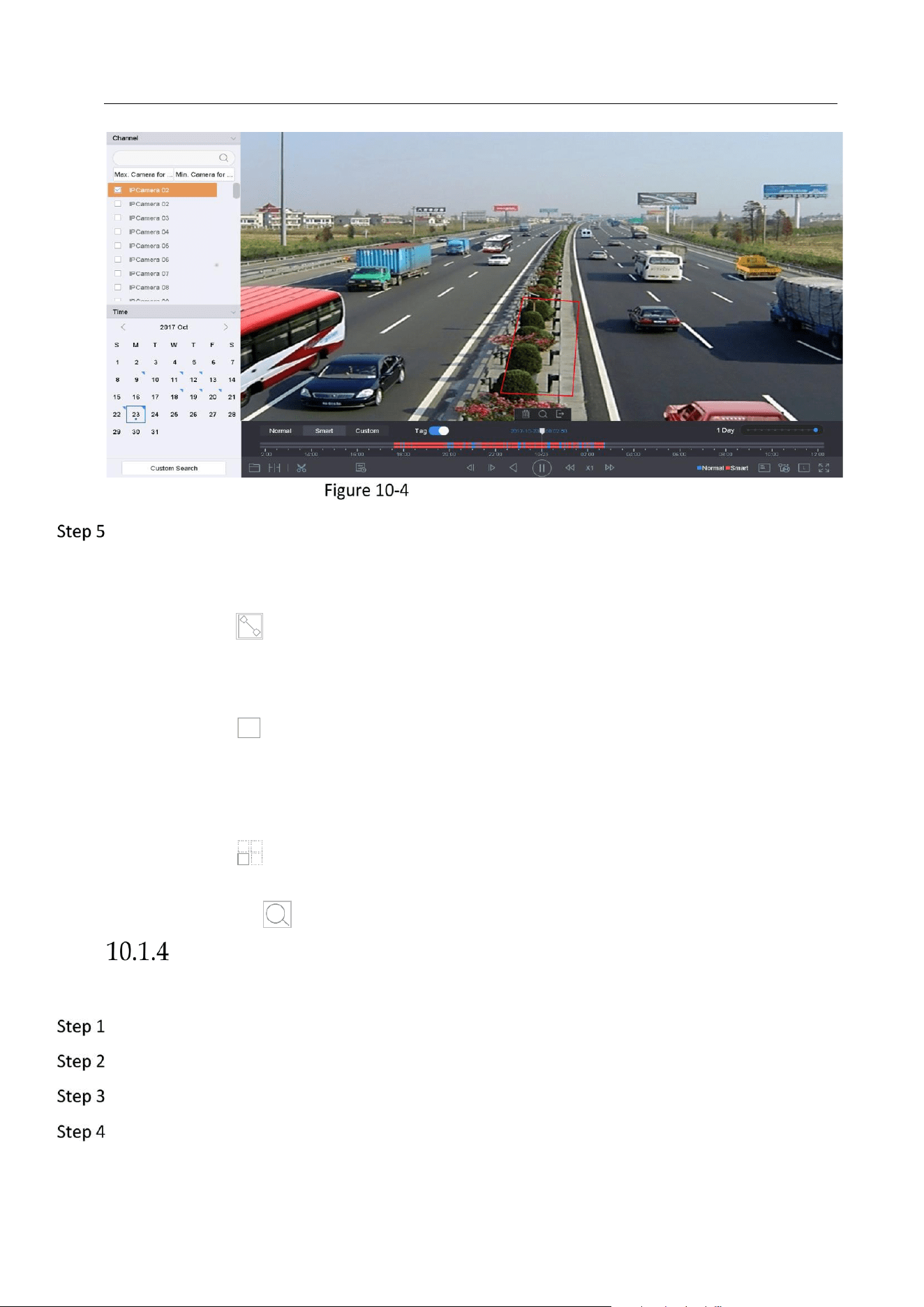
Network Video Recorder User Manual
95
Playback by Smart Search
Set the rules and areas for smart search of line crossing detection, intrusion detection or
motion detection event triggered recording.
Line Crossing Detection
1) Click the icon.
2) Click on the image to specify the start point and end point of the line.
Intrusion Detection
1) Click the icon.
2) Specify 4 points to set a quadrilateral region for intrusion detection. Only one region can
be set.
Motion Detection
1) Click the icon.
2) Hold the mouse on the image to draw the detection area manually.
3) Click Search to search the matched video and start to play it.
Play Custom Searched Files
You can play the files by custom search with different conditions.
Go to Playback.
Select a camera or cameras from the list.
Click Custom Search on the left bottom to enter the Search Condition interface.
Enter the search conditions for the files, e.g., time, file status, event type, etc.

Network Video Recorder User Manual
96
Custom Search
Click Search.
Custom Searched Video Files
On the search results interface, select a file and click to start playing the video.
Video Synopsis
Purpose:
Video synopsis is an approach to create a short video summary of a long video. It tracks and
analyzes moving objects (also called events), and converts video streams into a database of
objects and activities.
Before you start:
Enable Dual-VCA and intrusion detection/line crossing detection on the network camera.
Go to Playback interface.
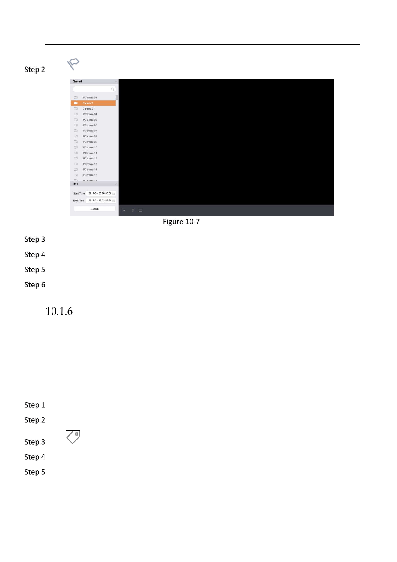
Network Video Recorder User Manual
97
Click in toolbar.
Synopsis Playback
Select a camera in channel list.
Specify Start Time and End Time. The duration must be within 24 hours.
Click Search to start play.
Optionally, double click a target on the playback window. A 60-second video of 30 seconds
before and after the time will be played.
Play Tag Files
Purpose:
Video tag allows you to record related information like people and location of a certain time
point during playback. You can use video tag(s) to search for video files and position time point.
Before playing back by tag:
Add Tag Files
Go to Playback.
Search and play back the video file(s).
Click to add the tag.
Edit the tag information.
Click OK.
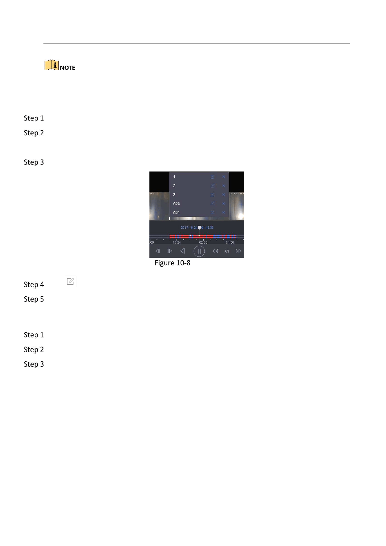
Network Video Recorder User Manual
98
Max. 64 tags can be added to a single video file.
Edit Tag Files
Go to Playback.
Click Tag.
The available tags are white marked and displayed in the time bar.
Point the white marked tag in the time bar to access the tag information.
Edit Tag Files
Click to edit the tag name.
Click OK.
Play Tag Files
Go to Playback.
Click Custom Search on the left bottom to enter the Search Condition interface.
Enter the search conditions for the tag files, including the time and the tag keyword.
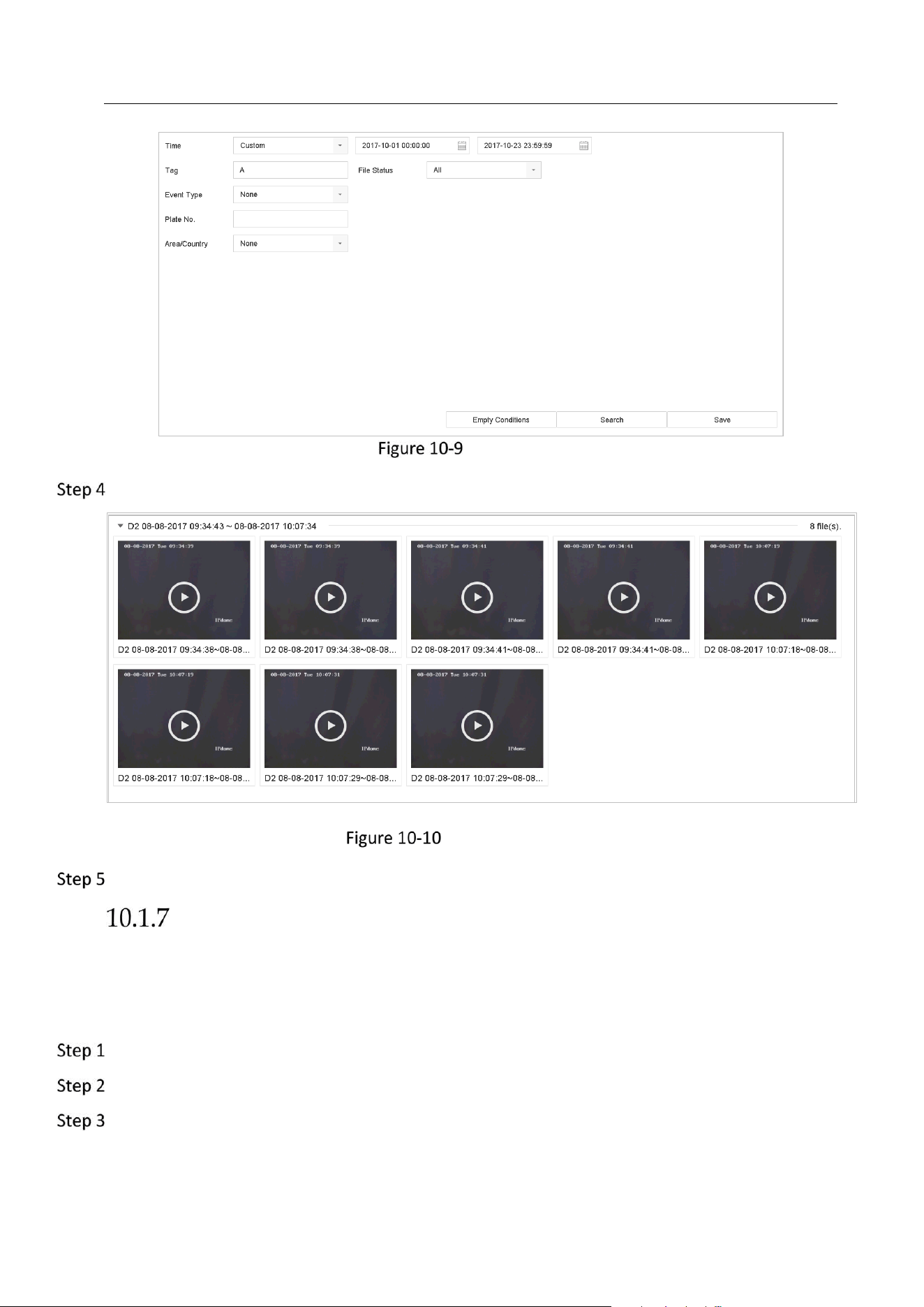
Network Video Recorder User Manual
99
Tag Search
Click Search.
Searched Tag Files
On the search results interface, select a tag file and click to start playing the video.
Play Event Files
Purpose
Play back video files on one or several channels searched by event type (e.g., alarm input,
motion detection, line crossing detection, face detection, vehicle detection, etc.).
Go to Playback.
Click Custom Search on the left bottom to enter the Search Condition interface.
Enter the search conditions for the event files, e.g., time, event type, file status, vehicle
information (for vehicle detection event), etc.
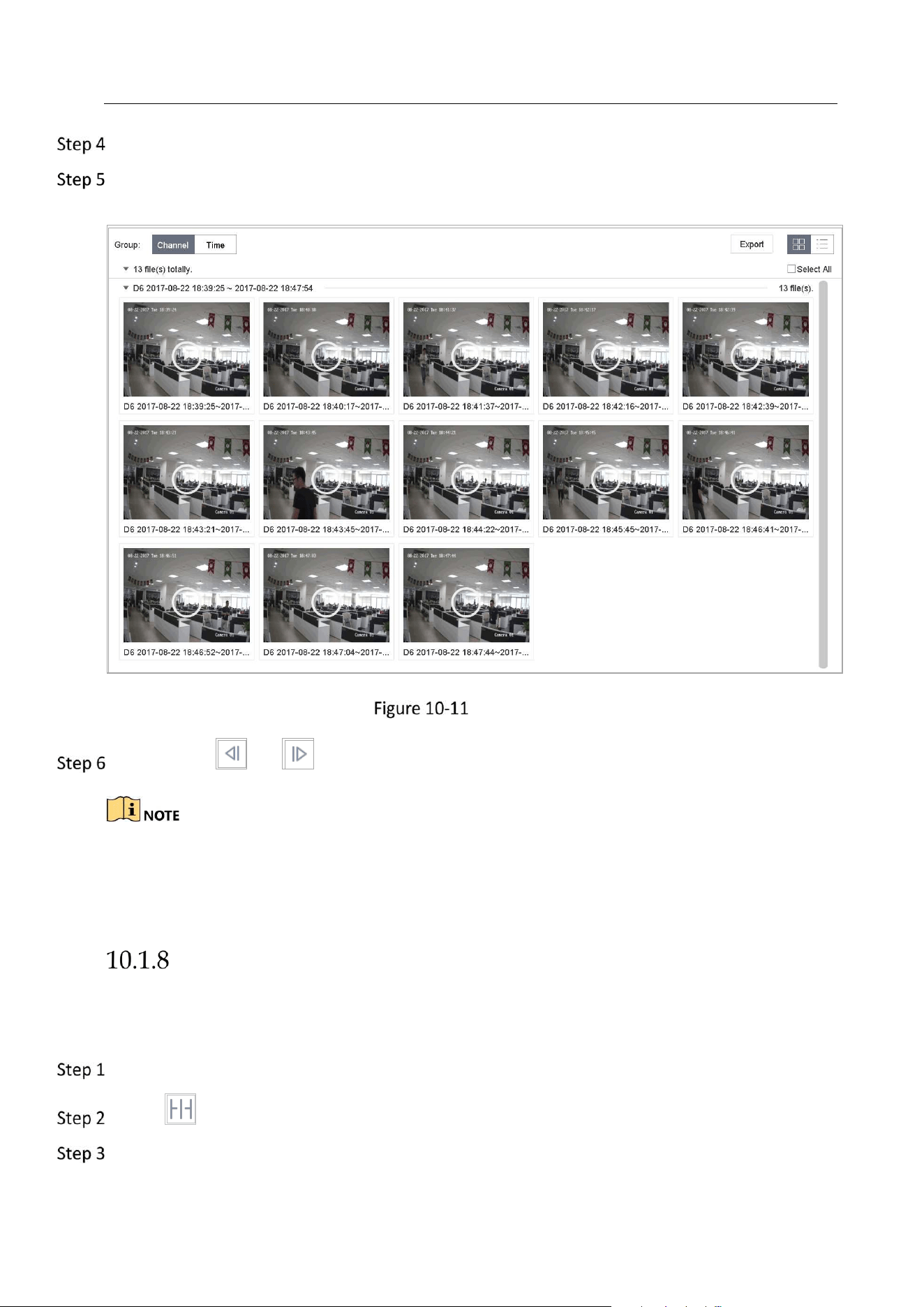
Network Video Recorder User Manual
100
Click Search.
On the search results interface, select an event video file/picture file and double click to start
playing the video.
Event Files
You can click or button to play 30s backward or forward.
Refer to Chapter 10 and Chapter 12 VCA Event Alarm for details for event and alarm
settings.
Refer to Chapter 7.7 Configure Event Triggered Recording for the event triggered
recording/capture settings.
Play by Sub-periods
Purpose:
The video files can be played in multiple sub-periods simultaneously on the screens.
Go to Playback.
Select icon at the left bottom corner to enter the sub-period playing mode.
Select a camera.
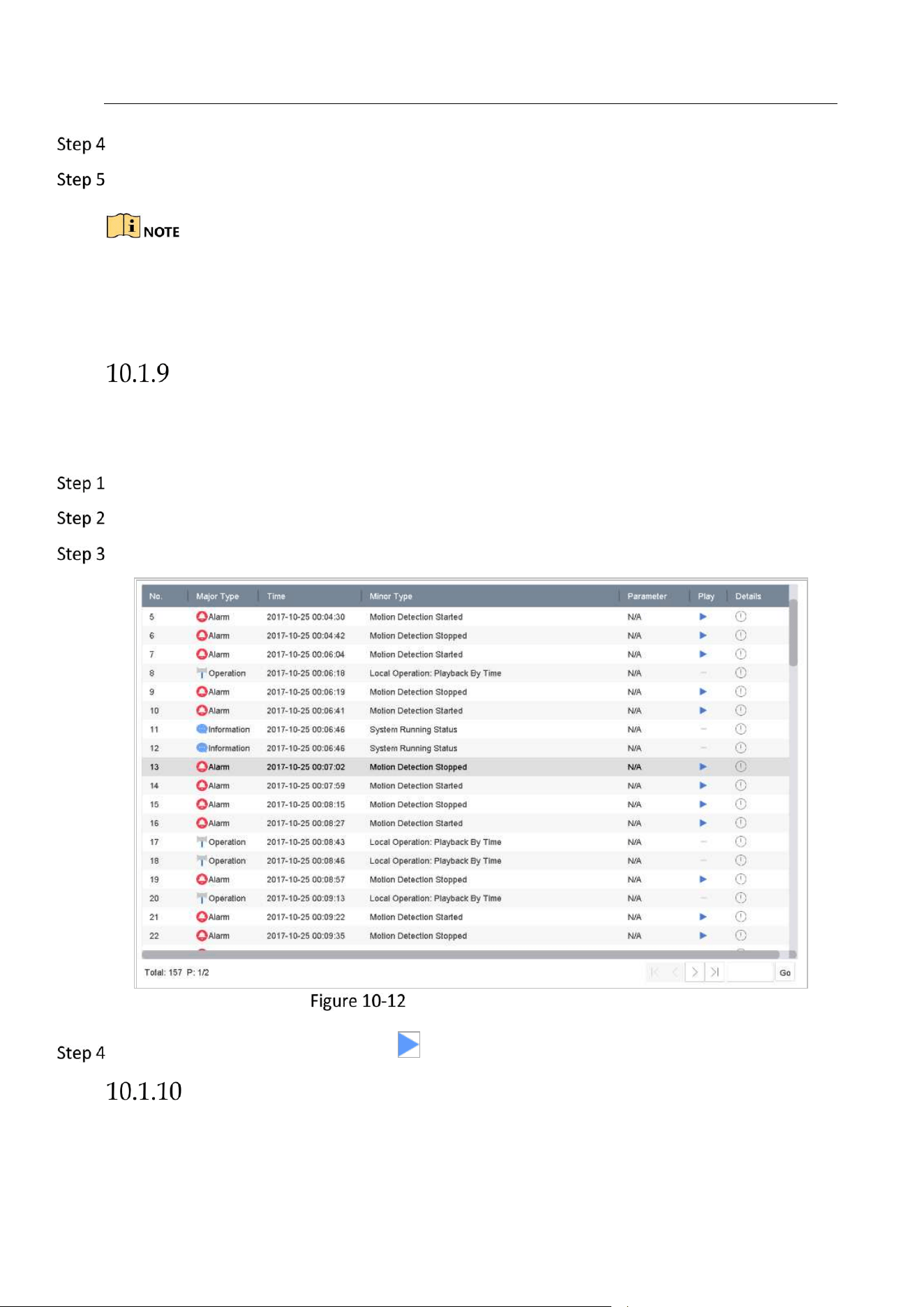
Network Video Recorder User Manual
101
Set the start time and end time for searching video.
Select the different multi-period at the right bottom corner, e.g., 4-Period.
According to the defined number of split-screens, the video files on the selected date can be
divided into average segments for playback. E.g., if there are video files existing between 16:00 and
22:00, and the 6-screen display mode is selected, then it can play the video files for 1 hour on each
screen simultaneously.
Play Log Files
Purpose:
Play back record file(s) associated with channels after searching system logs.
Go to Maintenance>Log Information.
Click Log Search tab to enter Playback by System Logs.
Set search time and type and click Search.
System Log Search Interface
Choose a log with video file and click to start playing the log file.
Play External File
Purpose:
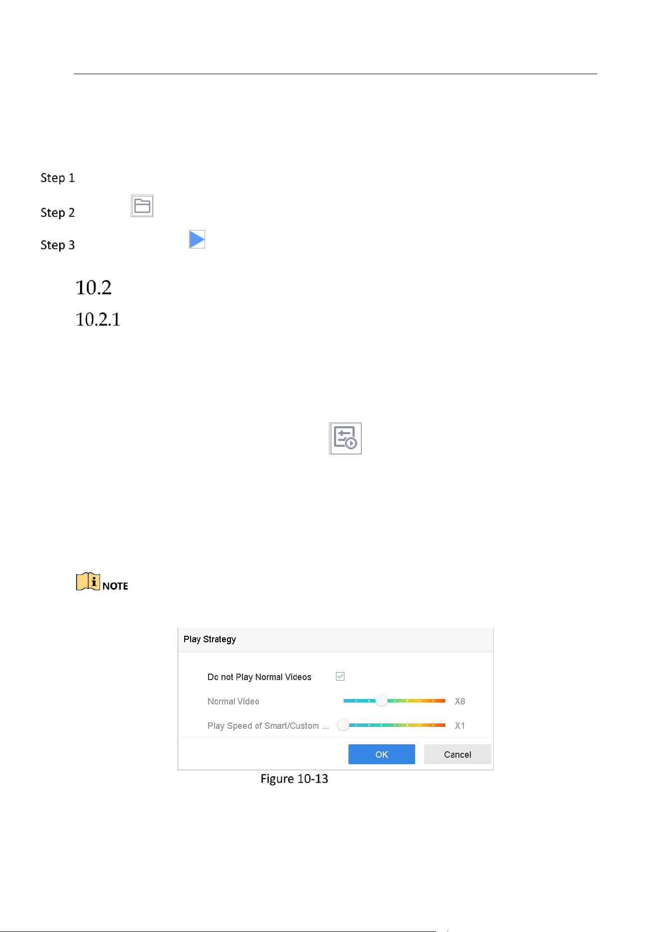
Network Video Recorder User Manual
102
You can play files from the external storage devices.
Before You Start:
Connect the storage device with the video files to your device.
Go to Playback.
Click the icon at the left bottom corner.
Select and click the button or double click to play the file.
Playback Operations
Set Play Strategy in Smart/Custom Mode
Purpose:
When you are in the smart or custom video playback mode, you can set the playing speed
separately for the normal video and the smart/custom video, or you can select to skip the
normal video.
In the Smart/Custom video playback mode, click to set the play strategy.
When Do not Play Normal Videos is checked, the device will skip the normal video and play
the smart (motion/line crossing/intrusion) video and the custom (searched video) only in
the normal speed (X1).
When Do not Play Normal Videos is unchecked, you can set the play speed for the normal
video the smart/custom video separately. The speed range is from X1 to XMAX.
You can set the speed in the single-channel play mode only.
Play Strategy
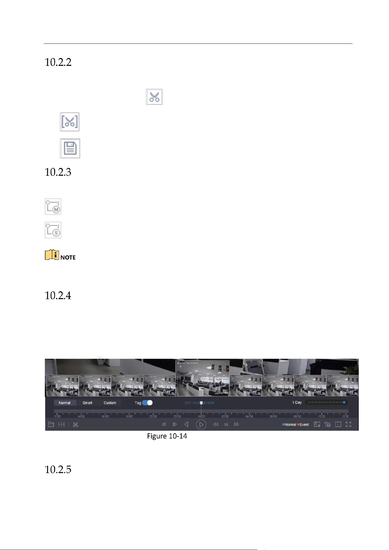
Network Video Recorder User Manual
103
Edit Video Clips
You can take video clips during the playback and export the clips.
In the video playback mode, click to start video clipping operation.
: Set the start time and end time of the video clipping.
: Export the video clips to the local storage device.
Switch between Main Stream and Sub-Stream
You can switch between the main stream and the sub-stream during the playback.
: Play the video in main stream.
: Play the video in sub-stream.
The encoding parameters for the main stream and sub-stream can be configured in Storage >
Encoding Parameters.
Thumbnails View
With the thumbnails view on the playback interface, you can conveniently locate the required
video files on the time bar.
In the video playback mode, move the mouse to the time bar to get the preview thumbnails of
the video files.
Thumbnails View
You can select and click on a required thumbnail to enter the full-screen playback.
Fisheye View
You can enter the fisheye expansion view during the video playback.
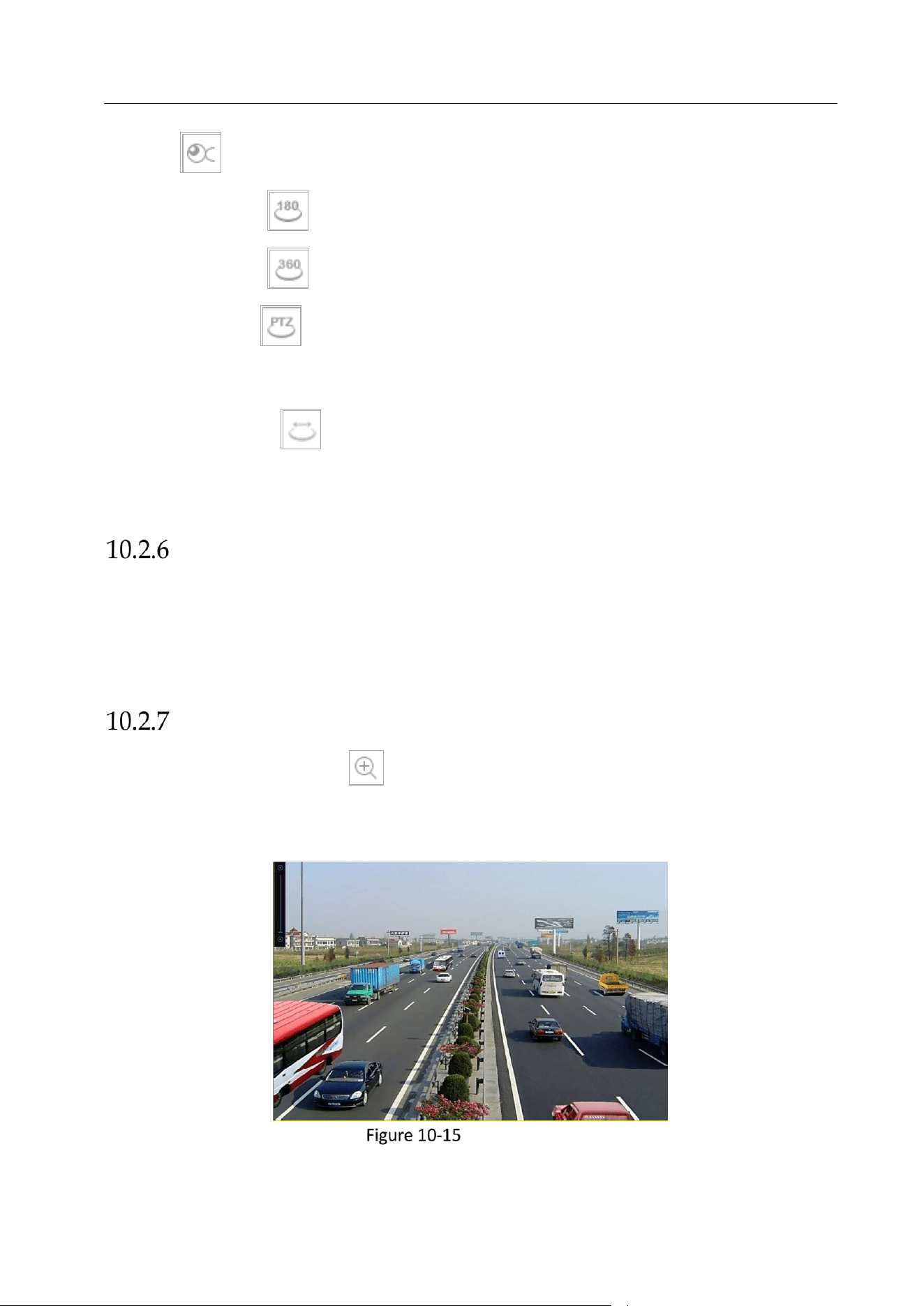
Network Video Recorder User Manual
104
Click the to enter the fisheye expansion mode.
180° Panorama ( ): Switch the live view image to the 180° panorama view.
360° Panorama ( ): Switch the live view image to the 360° panorama view.
PTZ Expansion ( ): The PTZ Expansion is the close-up view of some defined area in the
fisheye view or panorama expansion, and it supports the electronic PTZ function, which is
also called e-PTZ.
Radial Expansion ( ): In the radial expansion mode, the whole wide-angle view of the
fisheye camera is displayed. This view mode is called Fisheye View because it approximates
the vision of a fish’s convex eye. The lens produces curvilinear images of a large area, while
distorting the perspective and angles of objects in the image.
Fast View
You can hold the mouse to drag on the time bar to get the fast view of the video files.
In the video playback mode, use the mouse to hold and drag through the playing time bar to fast
view the video files.
Release the mouse to the required time point to enter the full-screen playback.
Digital Zoom
In the video playback mode, click from the toolbar to enter the digital zoom interface.
You can move the sliding bar or scroll the mouse wheel to zoom in/out the image to different
proportions (1 to16X).
Digital Zoom
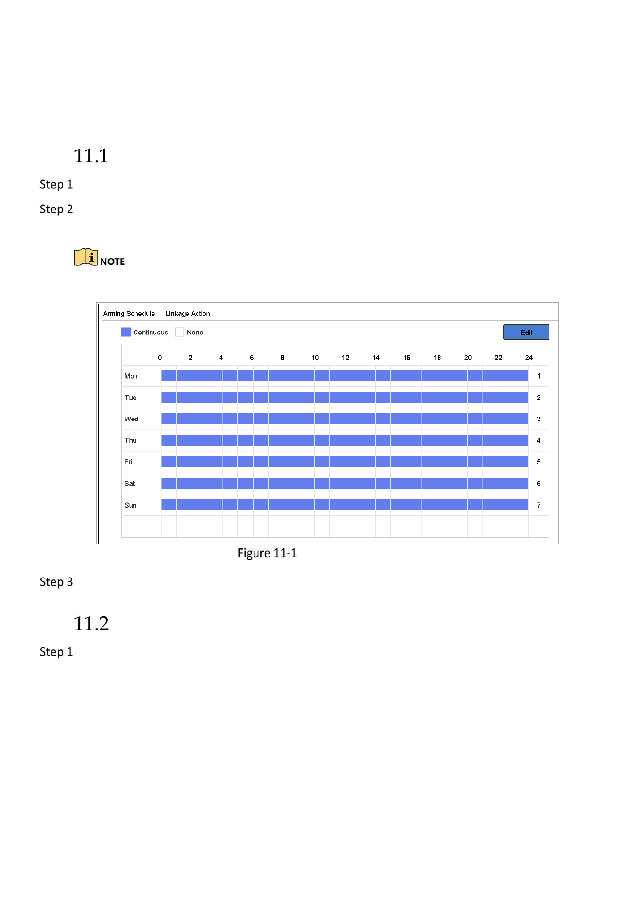
Network Video Recorder User Manual
105
Chapter 11 Event and Alarm Settings
Configure Arming Schedule
Select the Arming Schedule tab.
Choose one day of a week and set the time segment. Up to eight time periods can be set within
each day.
Time periods shall not be repeated or overlapped.
Set Arming Schedule
Click Apply to save the settings.
Configure Alarm Linkage Actions
Click Linkage Action to set the alarm linkage actions.
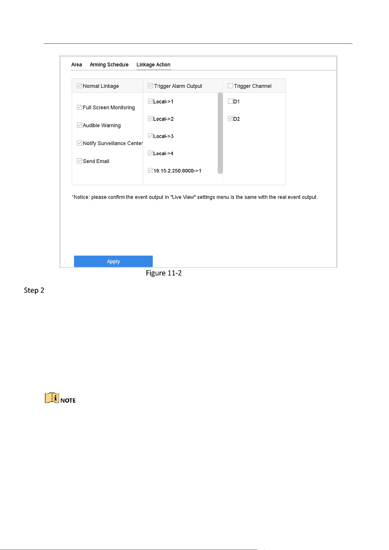
Network Video Recorder User Manual
106
Set Linkage Actions
Select the normal linkage actions, trigger alarm output or trigger recording channel.
Full Screen Monitoring
When an alarm is triggered, the local monitor displays in full screen the video image from the
alarming channel configured for full screen monitoring.
If alarms are triggered simultaneously in several channels, their full-screen images will be
switched at an interval of 10 seconds (default dwell time). A different dwell time can be set by
going to System>Live View > Full Screen Monitoring Dwell Time.
Auto-switch will terminate once the alarm stops and back to the live view interface.
You must select the channel(s) in Trigger Channel settings you want to trigger full screen
monitoring.
Audible Warning
It will trigger an audible beep when an alarm is detected.
Notify Surveillance Center
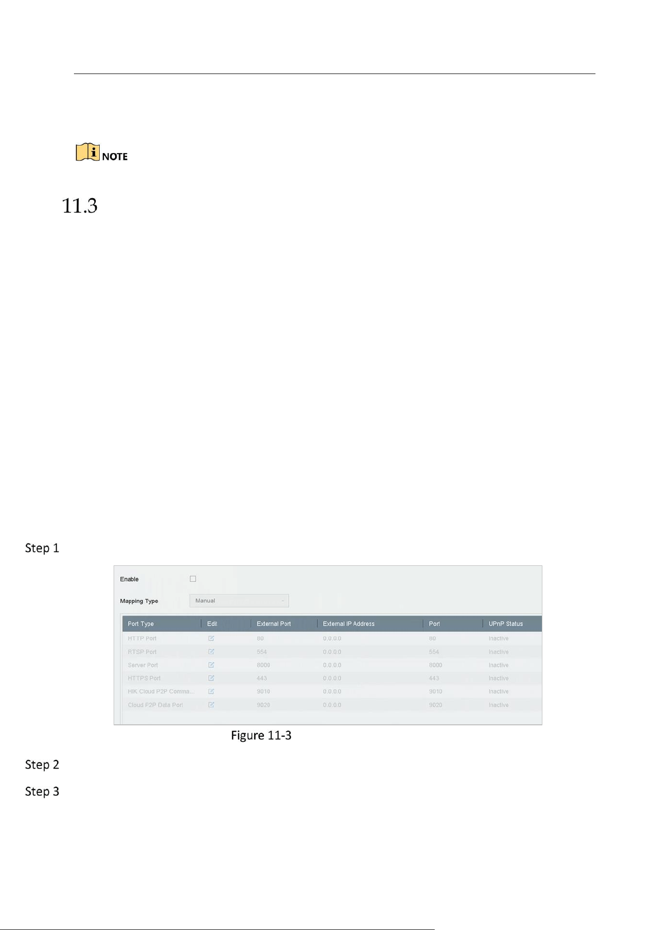
Network Video Recorder User Manual
107
It will send an exception or alarm signal to the remote alarm host when an event occurs. The
alarm host refers to the PC installed with Remote Client.
The alarm signal will be transmitted automatically at
detection mode when remote alarm host is configured.
Please refer to Chapter 14.8 Configuring NAT
Purpose:
Two ways are provided for port mapping to realize the remote access via the cross-segment
network, UPnP™ and manual mapping.
UPnP
TM
Universal Plug and Play (UPnP™) can permit the device seamlessly discover the presence of other
network devices on the network and establish functional network services for data sharing,
communications, etc. You can use the UPnP™ function to enable the fast connection of the device
to the WAN via a router without port mapping.
Before you start:
If you want to enable the UPnP™ function of the device, you must enable the UPnP™ function of
the router to which your device is connected. When the network working mode of the device is set
as multi-address, the Default Route of the device should be in the same network segment as that
of the LAN IP address of the router.
Go to Menu > Configuration > Network > NAT.
UPnP™ Settings Interface
Check Enable UPnP.
Select Mapping Type as Manual or Auto.
OPTION 1: Auto
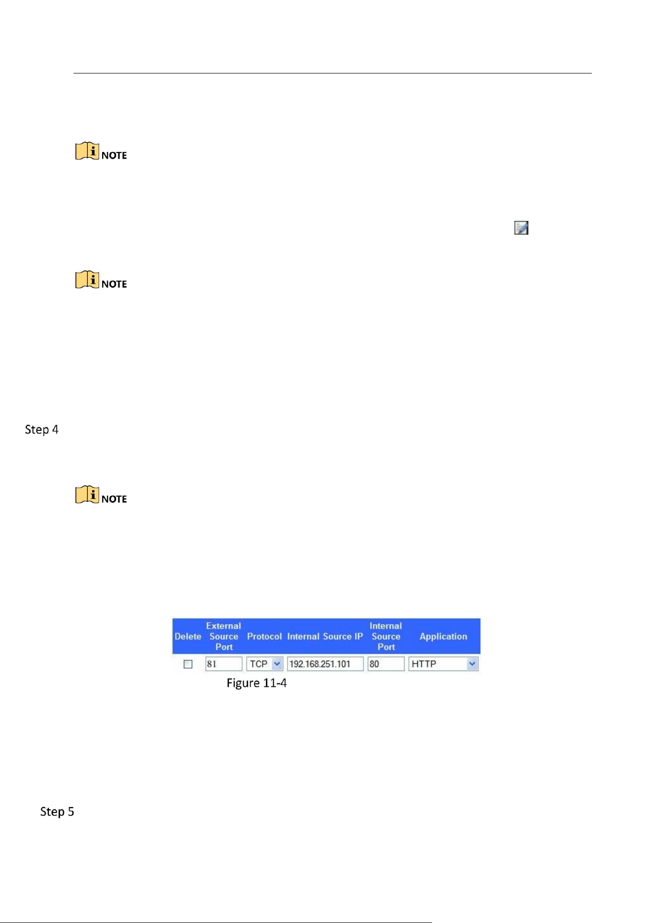
Network Video Recorder User Manual
108
If you select Auto, the port mapping items are read-only, and the external ports are set by the
router automatically.
You can click Refresh to get the latest status of the port mapping.
OPTION 2: Manual
If you select Manual, you can edit the external port on your demand by clicking to
activate External Port Settings.
You can use the default port No., or change it according to actual requirements.
External Port indicates the port No. for port mapping in the router.
The value of the RTSP port No. should be 554 or between 1024 and 65535, while the value
of the other ports should be between 1 and 65535 and the value must be different from
each other. If multiple devices are configured for the UPnP™ settings under the same
router, the value of the port No. for each device should be unique.
Enter the virtual server setting page of router; fill in the blank of Internal Source Port with the
internal port value, the blank of External Source Port with the external port value, and other
required contents.
Each item should be corresponding with the device port, including server port, http port,
RTSP port and https port.
The virtual server setting interface below is for reference only, it may be different due to
different router manufactures. Please contact the manufacture of router if you have any
problems with setting virtual server.
Setting Virtual Server Item
Configure Ports for alarm host configuration.
Send Email
It will send an email with alarm information to the user when an alarm is detected.
Please refer to 14.7 Configure Email for details of Email configuration.
Check the checkbox to select the alarm output when an alarm is triggered.
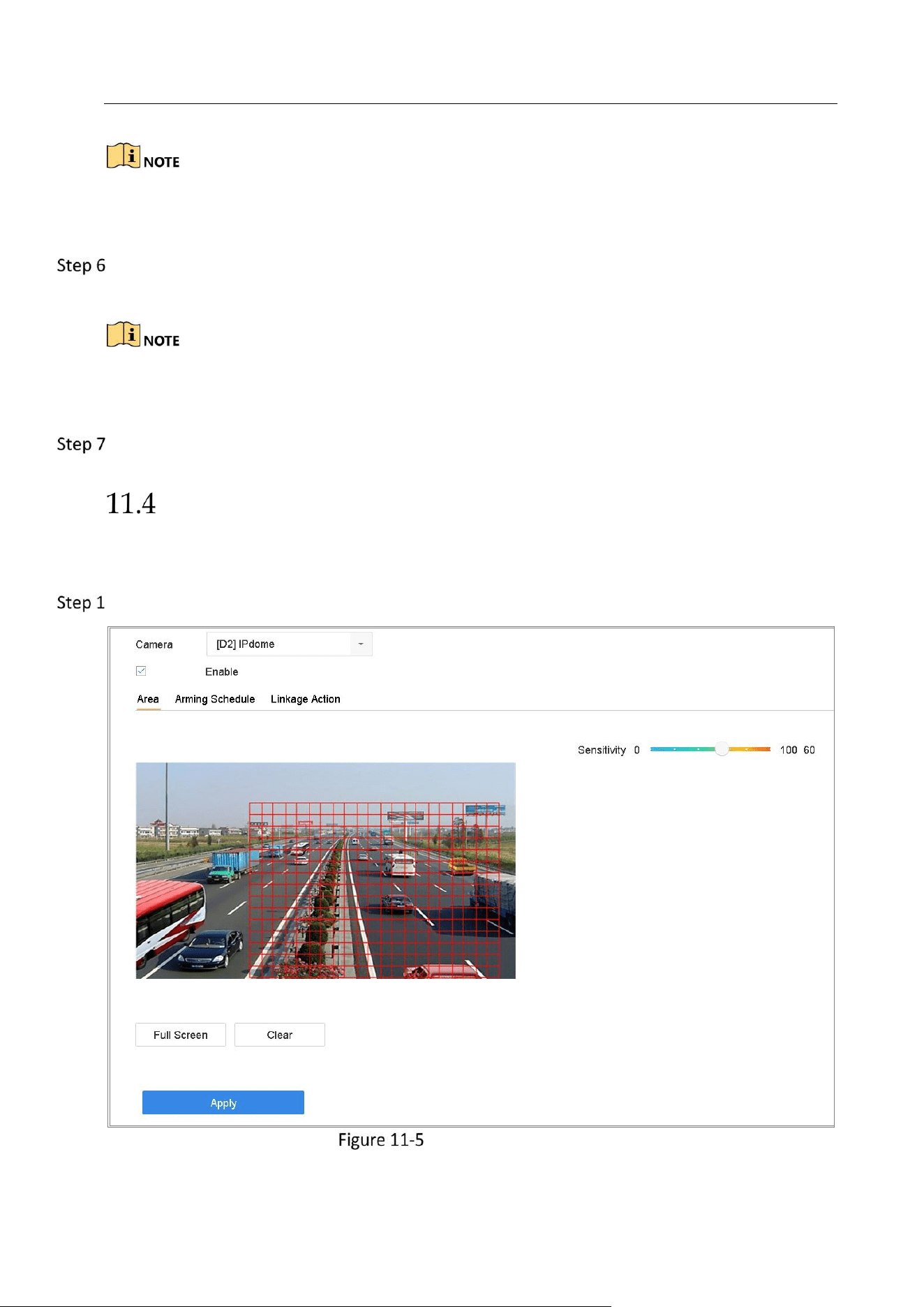
Network Video Recorder User Manual
109
To trigger an alarm output when an event occurs, please refer to Chapter 11.7.3 Configure Alarm
Output to set the alarm output parameters.
Click Trigger Channel and select one or more channels which will start to record/capture or
perform full-screen monitoring when motion alarm is triggered.
You have to set the recording schedule to realize this function. Please refer to Refer to Chapter
7.4 Configure Recording Schedule for settings of the recording schedule.
Click Apply to save the settings.
Configure Motion Detection Alarm
The motion detection enables the device to detect the moving objects in the monitoring area
and trigger the alarm.
Go to System> Event>Normal Event>Motion Detection.
Set Motion Detection

Network Video Recorder User Manual
110
Select the camera to configure the motion detection.
Check Enable.
Set the motion detection area.
Full screen: click to set the full-screen motion detection for the image.
Customized area: use the mouse to click and drag on the preview screen to draw the
customized motion detection area (s).
You can click Clear to clear the current motion detection area settings and draw again.
Set sensitivity (0-100). The sensitivity allows you to calibrate how readily movement triggers the
alarm. The higher value results in the more readily to trigger the motion detection.
Set the arming schedule. Refer to Chapter 11.1 Configure Arming Schedule.
Set the linkage actions. Refer to Chapter 11.2 Configure Alarm Linkage Actions.
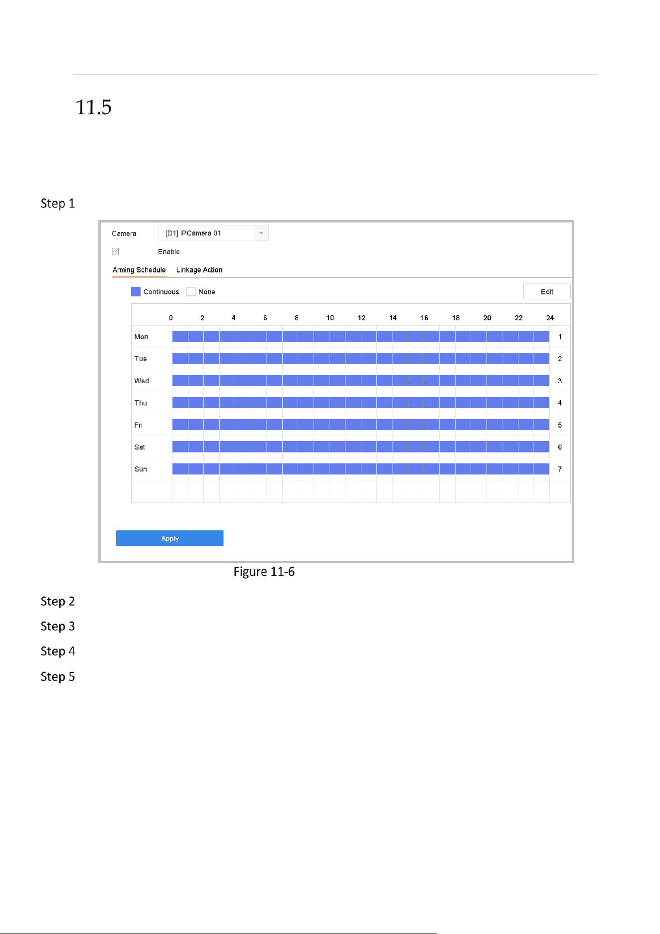
Network Video Recorder User Manual
111
Configure Video Loss Alarm
Purpose:
The video loss detection enables to detect video loss of a channel and take alarm response
action(s).
Go to System> Event>Normal Event>Video Loss.
Set Video Loss Detection
Select the camera to configure the video loss detection.
Check Enable.
Set the arming schedule. Refer to Chapter 11.1 Configure Arming Schedule.
Set the linkage actions. Refer to Chapter 11.2 Configure Alarm Linkage Actions
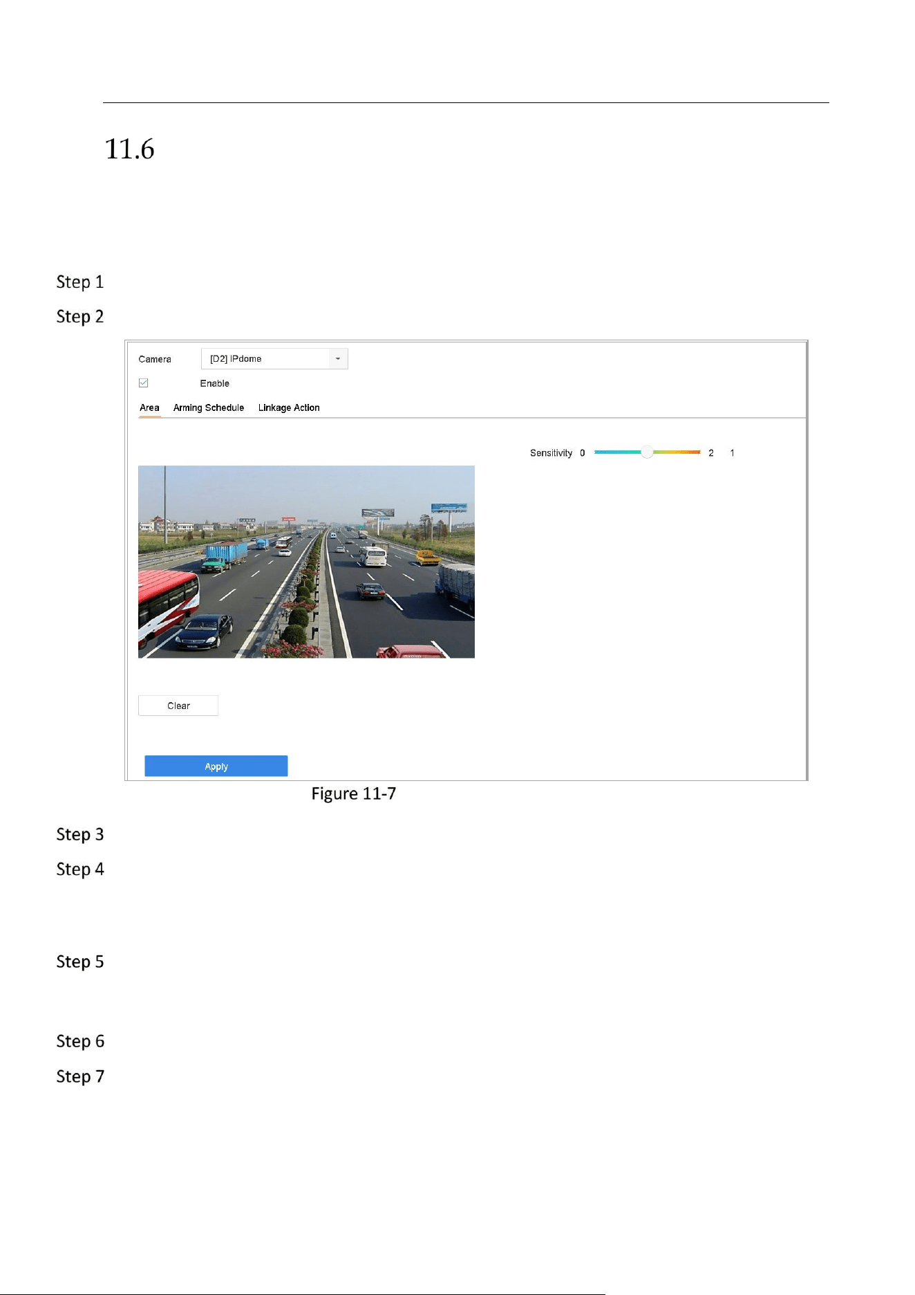
Network Video Recorder User Manual
112
Configure Video Tampering Alarm
Purpose:
The video tampering detection enables to trigger alarm when the camera lens is covered and
take alarm response action(s).
Go to System> Event>Normal Event>Video Tampering.
Select the camera to configure the video tampering detection.
Set Video Tampering Setting
Check Enable.
Set the video tampering area. Use the mouse to click and drag on the preview screen to draw
the customized video tampering area.
You can click Clear to clear the current area settings and draw again.
Set sensitivity level (0-2). 3 levels are available. The sensitivity allows you to calibrate how
readily movement triggers the alarm. The higher value results in the more readily to trigger the
video tampering detection.
Set the arming schedule. Refer to Chapter 11.1 Configure Arming Schedule.
Set the linkage actions. Refer to Chapter 11.2 Configure Alarm Linkage Actions。
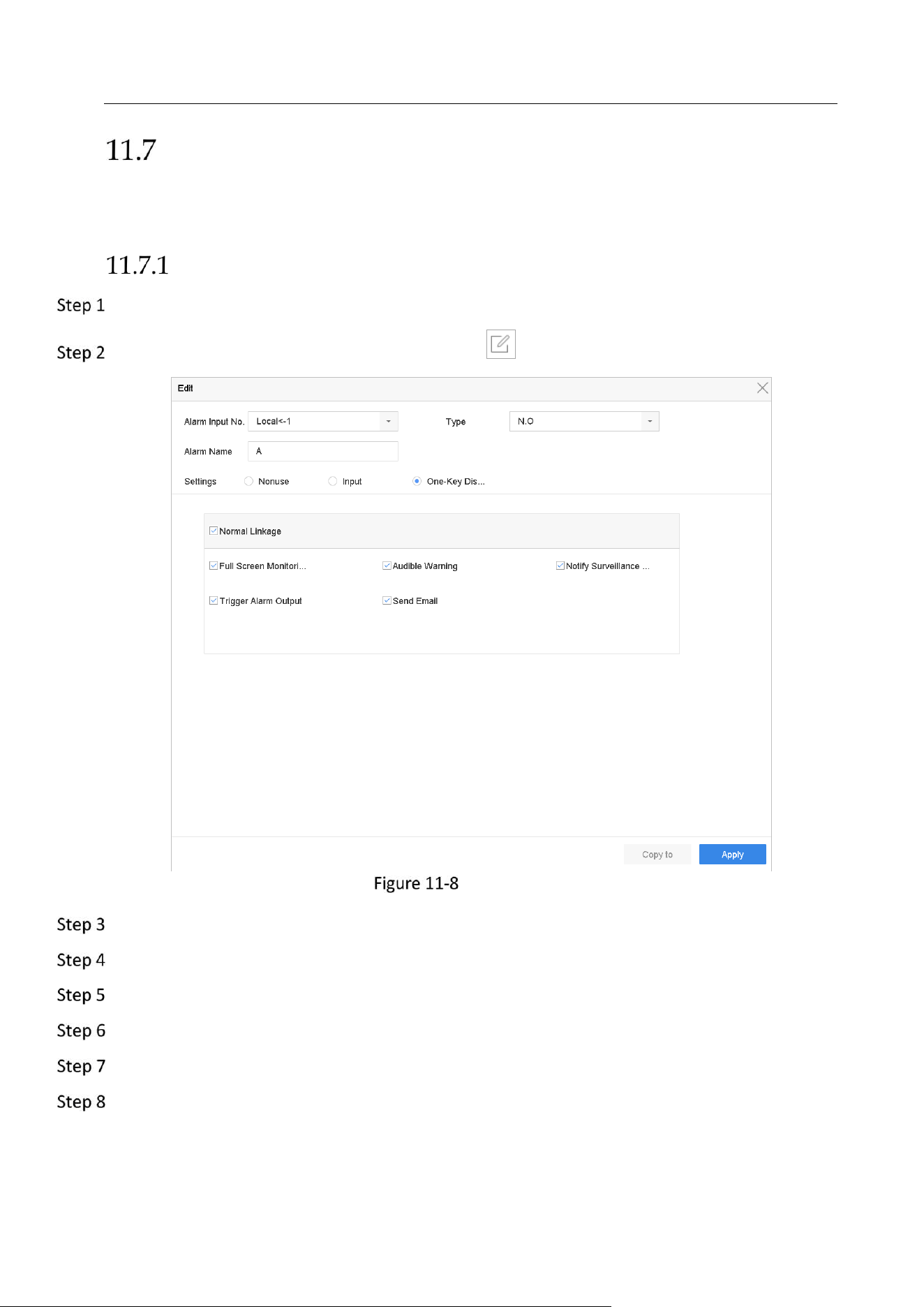
Network Video Recorder User Manual
113
Configure Sensor Alarms
Purpose:
Set the handling action of an external sensor alarm.
Configure Alarm Input
Go to System> Event>Normal Event>Alarm Input.
Select an alarm input item from the list and click .
Alarm Input
Select the alarm input type to N.C or N.O.
Edit the alarm name.
Check the radio button of Input.
Set the arming schedule. Refer to Chapter 11.1 Configure Arming Schedule.
Set the linkage actions. Refer to Chapter 11.2 Configure Alarm Linkage Actions。
Click Apply and follow the message box to reboot device to take effect the settings.
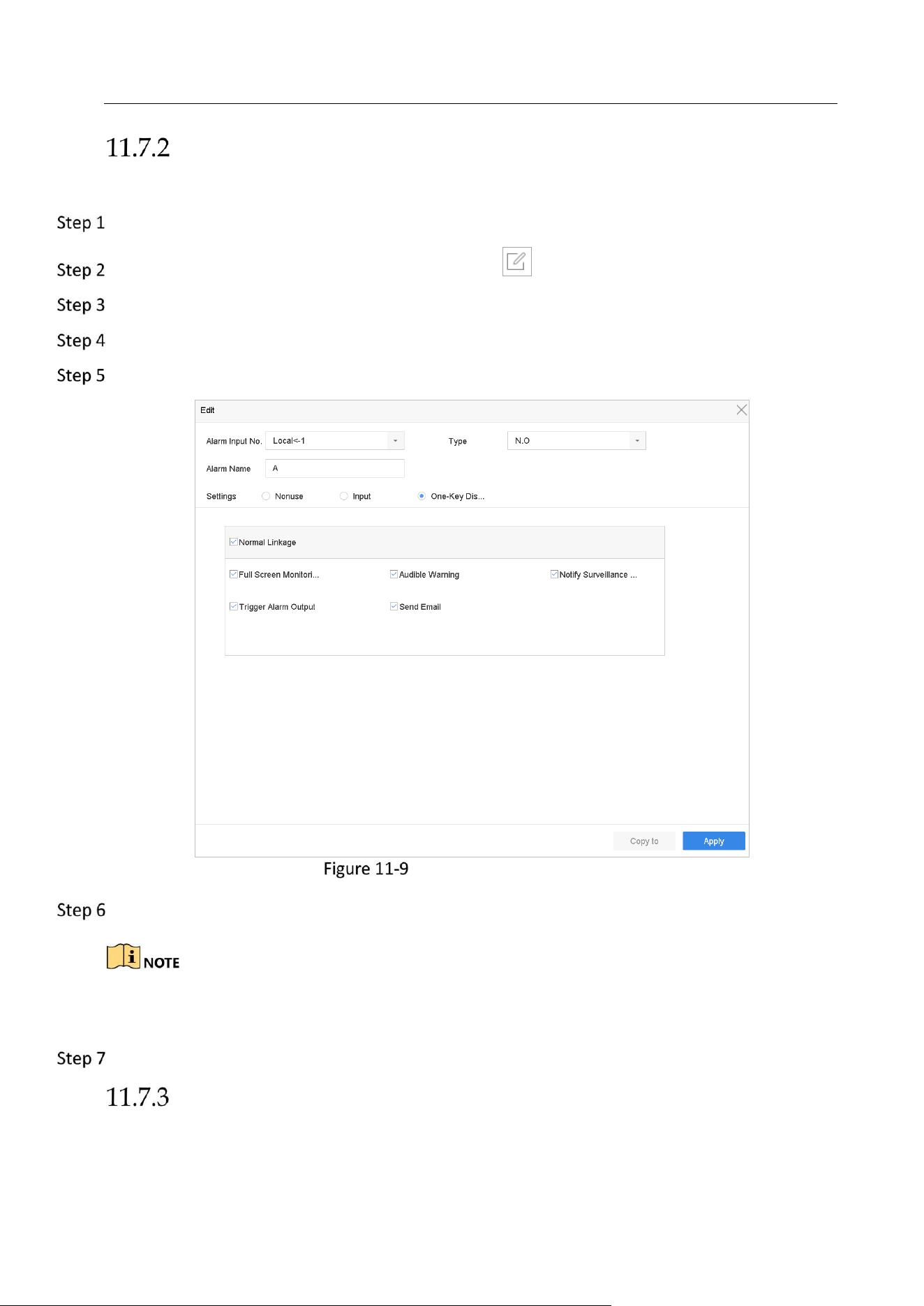
Network Video Recorder User Manual
114
Configure One-Key Disarming
The one-key disarming enables the device to disarm the alarm input 1 by one-key operation.
Go to System> Event>Normal Event>Alarm Input.
Select the alarm input1 item from the list and click .
Select the alarm input type to N.C or N.O.
Edit the alarm name.
Check the radio button of Enable One-Key Disarming.
One-Key Alarm Disarming
Select the alarm linkage action (s) you want to disarm for the local alarm input1.
When the alarm input 1 (Local<-1) is enabled with one-key disarming, the other alarm input
settings are not configurable.
Click Apply to save the settings.
Configure Alarm Output
Trigger an alarm output when an alarm is triggered.
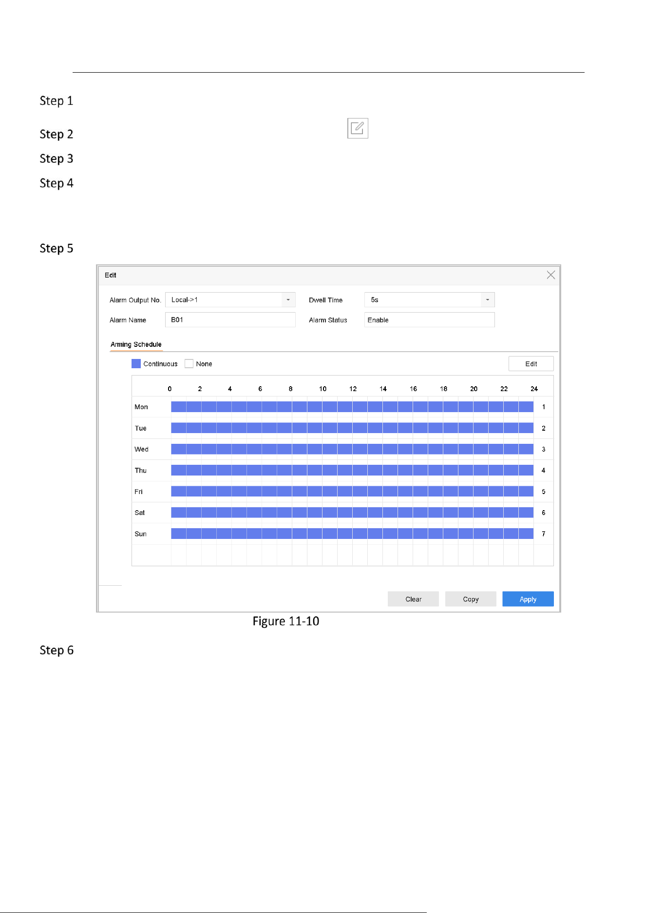
Network Video Recorder User Manual
115
Go to System> Event>Normal Event>Alarm Output.
Select an alarm output item from the list and click .
Edit the alarm name.
Select the dwell time (the alarm duration) from 5s to 600s, or Manually Clear.
Manually Clear: you should manually clear the alarm when the alarm occurs. Refer to Chapter
11.10 Trigger or Clear Alarm Output Manually for detailed instructions.
Set the arming schedule. Refer to Chapter 11.1 Configure Arming Schedule.
Alarm Output
(Optional) You can click Copy to copy the same settings to other alarm output (s).
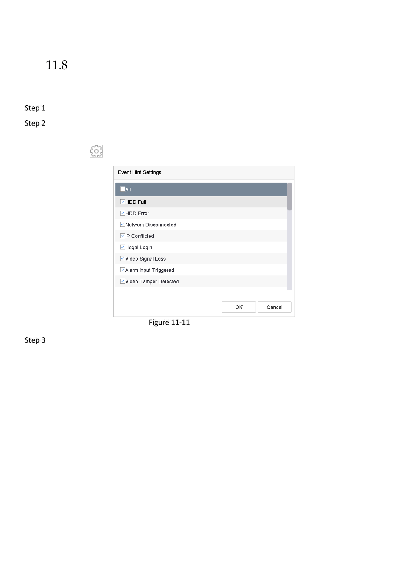
Network Video Recorder User Manual
116
Configure Exceptions Alarm
The exception events can be configured to take the event hint in the live view window, trigger
alarm output and linkage actions.
Go to System> Event>Normal Event>Exception.
(Optional) Enable the event hint if you want to display the event hint in the live view window.
1) Check the checkbox of Enable Event Hint.
2) Click to select the exception type (s) to take the event hint.
Event Hint Settings
Select the excetion type from the drop-down list to set the linkage actions.
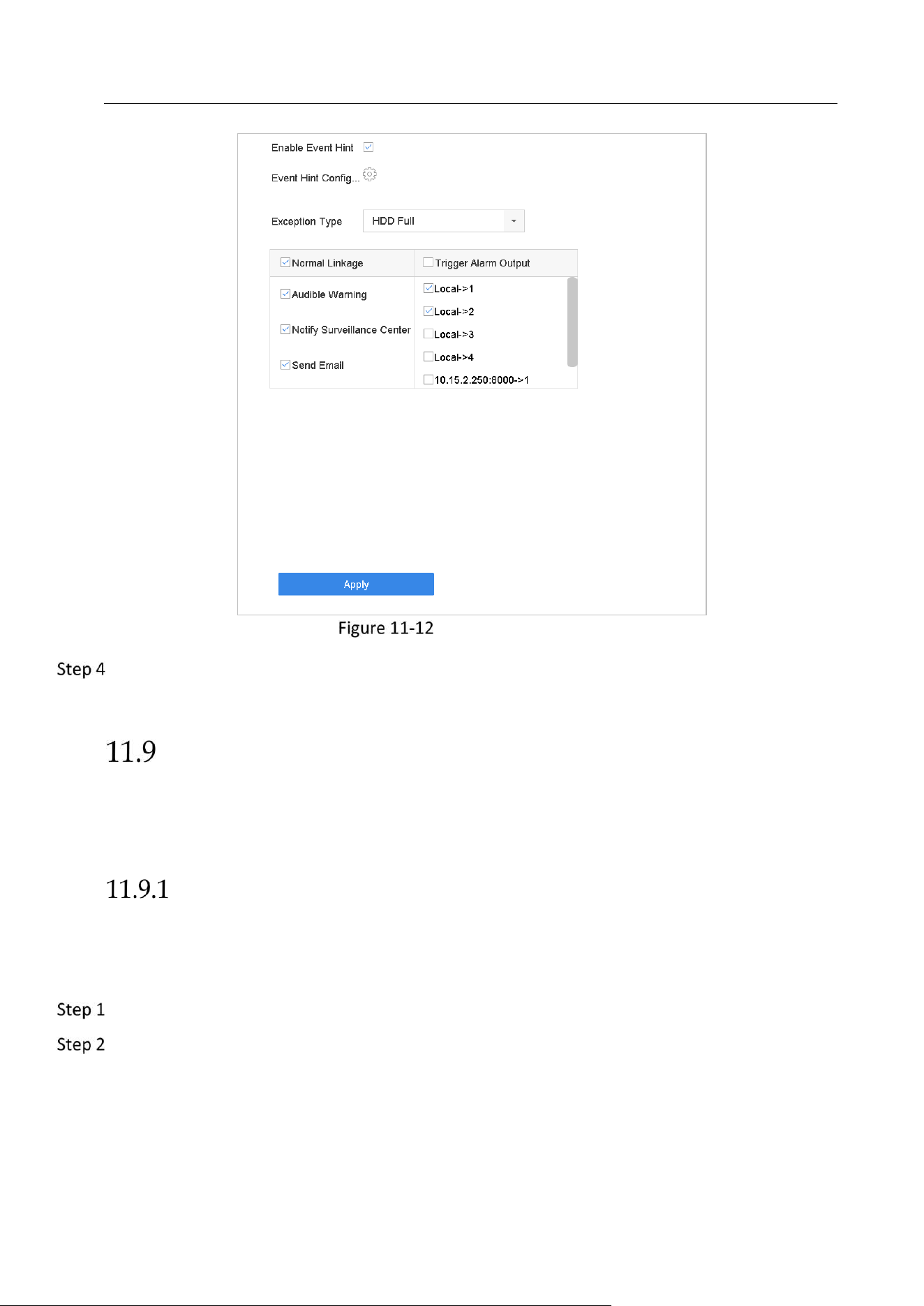
Network Video Recorder User Manual
117
Exceptions Handling
Set the normal linkage and alarm output triggering. Refer to 11.2 Configure Alarm Linkage
Actions.
Alarm Linkage Actions
Purpose:
Alarm linkage actions will be activated when an alarm or exception occurs, including Event Hint
Display, Full Screen Monitoring, Audible Warning (buzzer), Trigger Alarm Output, etc.
Configure Auto-switch Full Screen Monitoring
When an alarm is triggered, the local monitor displays in full screen the video image from the
alarming channel configured for full screen monitoring. And when the alarm is triggered
simultaneously in several channels, you must configure the auto-switch dwell time.
Go to System > View > General.
Set the event output and dwell time.
Event Output: Select the output to show event video.
Full Screen Monitoring Dwell Time: Set the time in seconds to show alarm event screen. If
alarms are triggered simultaneously in several channels, their full-screen images will be
switched at an interval of 10 seconds (default dwell time).
Network Video Recorder User Manual
118
Go to the Linkage Action interface of the alarm detection (e.g., motion detection, video
tampering, face detection, etc.).
Select the Full Screen Monitoring alarm linkage action.
Select the channel(s) in Trigger Channel settings you want to make full screen monitoring.
Auto-switch will terminate once the alarm stops and back to the live view interface.
Configure Audio Warning
The audio warning enables the system to trigger an audible beep when an alarm is detected.
Go to System>View>General.
Enable the audio output and set the volume.
Go to the Linkage Action interface of the alarm detection (e.g., motion detection, video
tampering, face detection, etc.).
Select the Audio Warning alarm linkage action.
Notify Surveillance Center
The device can send an exception or alarm signal to the remote alarm host when an event
occurs. The alarm host refers to the PC installed with client software (e.g., iVMS-4200, iVMS-
5200).
Go to System > Network > Advanced > More Settings.
Set the alarm host IP and alarm host port.
Go to the Linkage Action interface of the alarm detection (e.g., motion detection, video
tampering, face detection, etc.).
Select the Notify Surveillance Center.
Configure Email Linkage
The system can send an email with alarm information to a user or users when an alarm is
detected.
Please refer to Chapter 14.7 Configure Email for details of Email configuration.
Go to System>Network>Advanced.
Configure the Email settings.
Go to the Linkage Action interface of the alarm detection (e.g., motion detection, video
tampering, face detection, etc.).
Select the Send Email alarm linkage action.
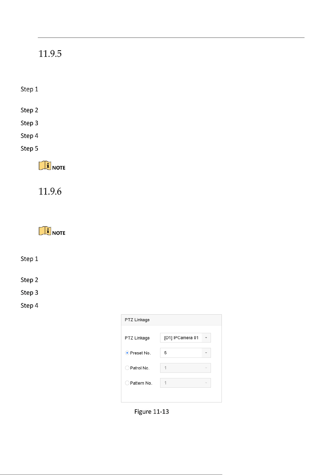
Network Video Recorder User Manual
119
Trigger Alarm Output
The alarm output can be triggered by the alarm input, motion detection, video tampering
detection, face detection, line crossing detection, and all other events.
Go to the Linkage Action interface of the alarm input or event detection (e.g., motion
detection, face detection, line crossing detection, intrusion detection, etc.).
Click the Trigger Alarm Output tab.
Select the alarm output (s) to trigger.
Go to System> Event>Normal Event>Alarm Output.
Select an alarm output item from the list.
Refer to Chapter 11.7.3 Configure Alarm Output for the alarm output settings.
Configure PTZ Linkage
The system can trigger the PTZ actions (e.g., call preset/patrol/pattern) when the alarm event,
or VCA detection events occur.
Make sure the PTZ or speed dome connected supports PTZ linkage.
Go to the Linkage Action interface of the alarm input or VCA detection (e.g., face detection, line
crossing detection, intrusion detection, etc.).
Select the PTZ Linkage.
Select the camera to perform the PTZ actions.
Select the preset/patrol/pattern No. to call when the alarm events occur.
PTZ Linkage
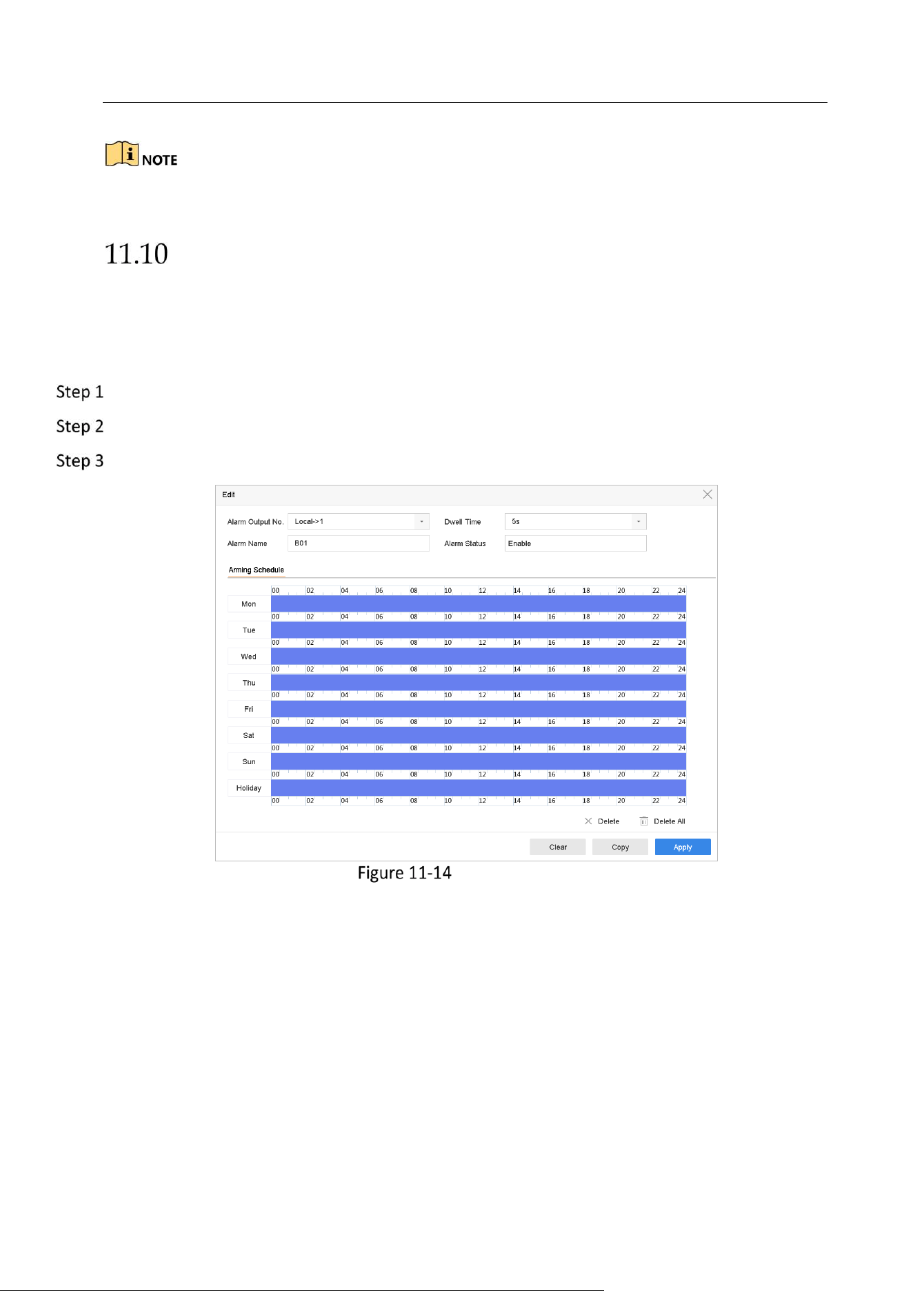
Network Video Recorder User Manual
120
You can set one PTZ type only for the linkage action each time.
Trigger or Clear Alarm Output Manually
Purpose:
Sensor alarm can be triggered or cleared manually. When the Manually Clear is selected for the
dwell time of an alarm output, the alarm can be cleared only by clicking Clear button.
Go to System> Event>Normal Event>Alarm Output.
Select the alarm output you want to trigger or clear.
Click Trigger/Clear to trigger or clear an alarm output.
Alarm Output

Network Video Recorder User Manual
121
Chapter 12 VCA Event Alarm
The device supports receiving the VCA detections sent by connected IP cameras. Enable and
configure the VCA detection on the IP camera settings interface first.
VCA detections must be supported by the connected IP camera.
Refer to the User Manual of Network Camera for the detailed instructions for the VCA
detection.
Face Detection
Purpose:
Face detection function detects the face appears in the scene. Linkage actions will be triggered
when a human face is detected.
Go to System > Event > Smart Event.
Select a camera to configure.
Click Face Detection.
Face Detection
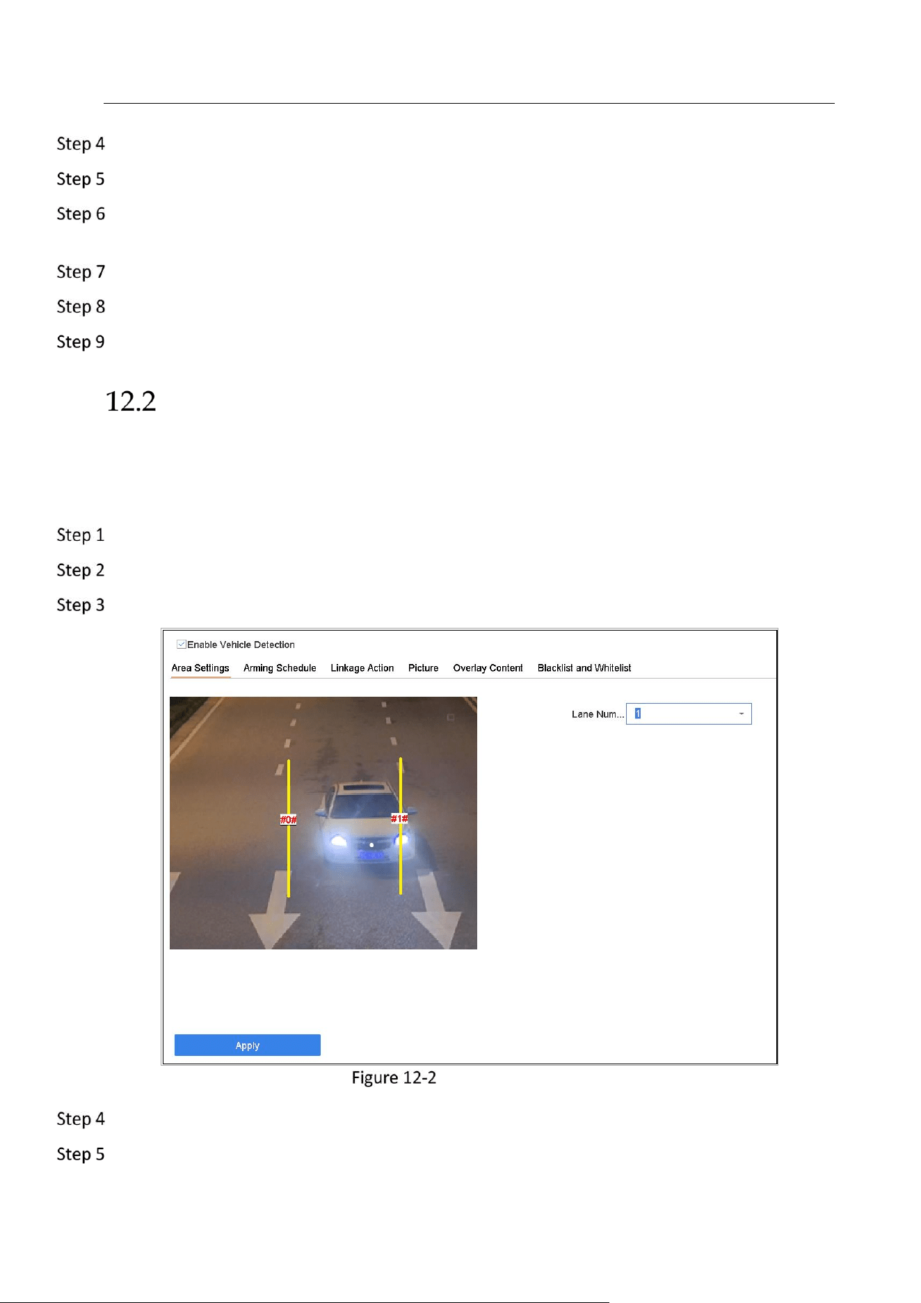
Network Video Recorder User Manual
122
Check Enable Face Detection.
Optionally, check Save VCA Picture to save the captured pictures of face detection.
Drag the Sensitivity slider to set the detection sensitivity. Sensitivity range: [1-5]. The higher
the value is, the more easily the face can be detected.
Set the arming schedule. Refer to Chapter 11.1 Configure Arming Schedule.
Set the linkage actions. Refer to Chapter 11.2 Configure Alarm Linkage Actions.
Click Apply.
Vehicle Detection
Purpose:
Vehicle Detection is available for the road traffic monitoring. In Vehicle Detection, the passed
vehicle can be detected and the picture of its license plate can be captured.
Go to System > Event > Smart Event.
Select a camera to configure.
Click Vehicle.
Vehicle Detection
Check Enable Vehicle Detection.
Optionally, check Save VCA Picture to save the captured pictures of vehicle detection.
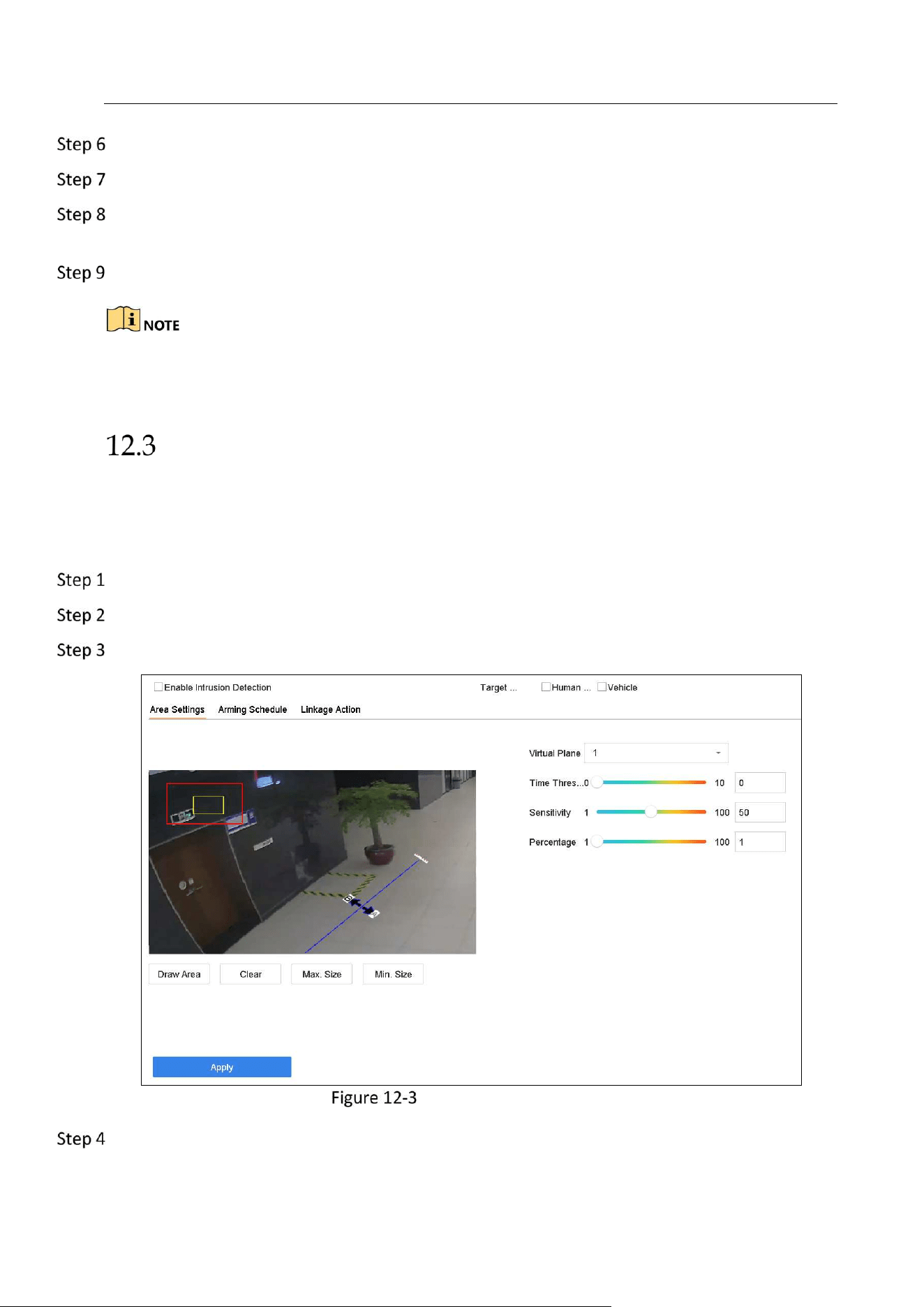
Network Video Recorder User Manual
123
Set the arming schedule. Refer to Chapter 11.1 Configure Arming Schedule.
Set the linkage actions. Refer to Chapter 11.2 Configure Alarm Linkage Actions
Configure rules, including Area Settings, Picture, Overlay Content, and Blacklist and Whitelist.
Area Settings: Up to 4 lanes are selectable.
Click Save.
Refer to the User Manual of Network Camera for the detailed instructions for the vehicle
detection.
Line Crossing Detection
Purpose:
Line crossing detection detects people, vehicles, and objects crossing a set virtual line. The
detection direction can be set as bidirectional, from left to right or from right to left.
Go to System > Event > Smart Event.
Click Line Crossing.
Select a camera to configure.
Line Crossing Detection
Check Enable Line Crossing Detection.

Network Video Recorder User Manual
124
Optionally, check Save VCA Picture to save the captured pictures of line crossing detection.
Follow the steps to set the line crossing detection rules and detection areas.
1) Select Arming Region to configure. Up to 4 arming regions are selectable.
2) Select the Direction as A<->B, A->B, or A<-B.
A<->B: Only the arrow on the B side shows. When an object goes across the configured
line with both direction can be detected and alarms are triggered.
A->B: Only the object crossing the configured line from the A side to the B side can be
detected.
B->A: Only the object crossing the configured line from the B side to the A side can be
detected.
3) Set the detection sensitivity. The higher the value is, the more easily the detection alarm
can be triggered.
4) Click Draw Region and set two points in the preview window to draw a virtual line.
Draw the maximum size/minimum size for targets. Only the targets in the size ranging from
max. size to min. size will trigger line crossing detection.
1) Click Max. Size/Min. Size.
2) Draw an area in preview window.
3) Click Stop Drawing.
Set the arming schedule. Refer to Chapter 11.1 Configure Arming Schedule.
Set the linkage actions. Refer to Chapter 11.2 Configure Alarm Linkage Actions.
Click Apply.
Intrusion Detection
Purpose:
Intrusion detection function detects people, vehicle or other objects which enter and loiter in a
pre-defined virtual region, and some certain actions can be taken when the alarm is triggered.
Go to System > Event > Smart Event.
Click Intrusion.
Select a camera to configure.
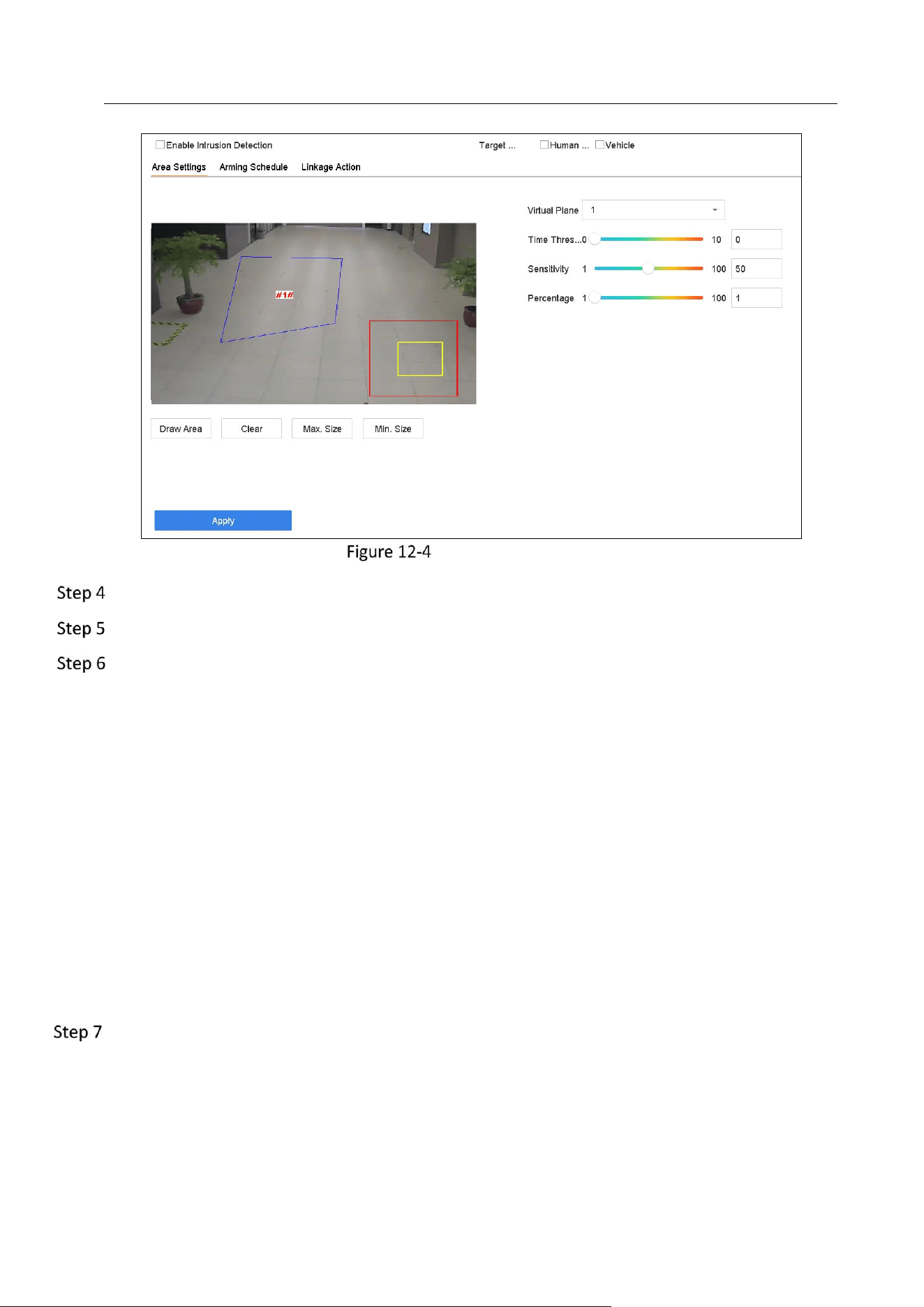
Network Video Recorder User Manual
125
Intrusion Detection
Check Enable Intrusion Detection.
Optionally, check Save VCA Picture to save the captured pictures of intrusion detection.
Follow the steps to set the detection rules and detection areas.
1) Select a Virtual Panel to configure. Up to 4 virtual panels are selectable.
2) Drag the sliders to set Time Threshold, Sensitivity, and Percentage.
Time Threshold: The threshold for the time of the object loitering in the region. When
the duration of the object in the defined detection area is longer than the threshold,
device will trigger an alarm. Its range is [1s-10s].
Sensitivity: The size of the object that can trigger the alarm. The higher the value is,
the more easily the detection alarm can be triggered. Its range is [1-100].
Percentage: The ratio of the in-region part of the object that can trigger the alarm. For
example, if the percentage is 50%, when the object enters the region and occupies half
of the whole region, device will trigger an alarm. Its range is [1-100].
3) Click Draw Region and draw a quadrilateral in the preview window by specifying four
vertexes of the detection region.
Draw the maximum size/minimum size for targets. Only the targets in the size ranging from
max. size to min. size will trigger intrusion detection.
1) Click Max. Size/Min. Size.
2) Draw an area in preview window.
3) Click Stop Drawing.
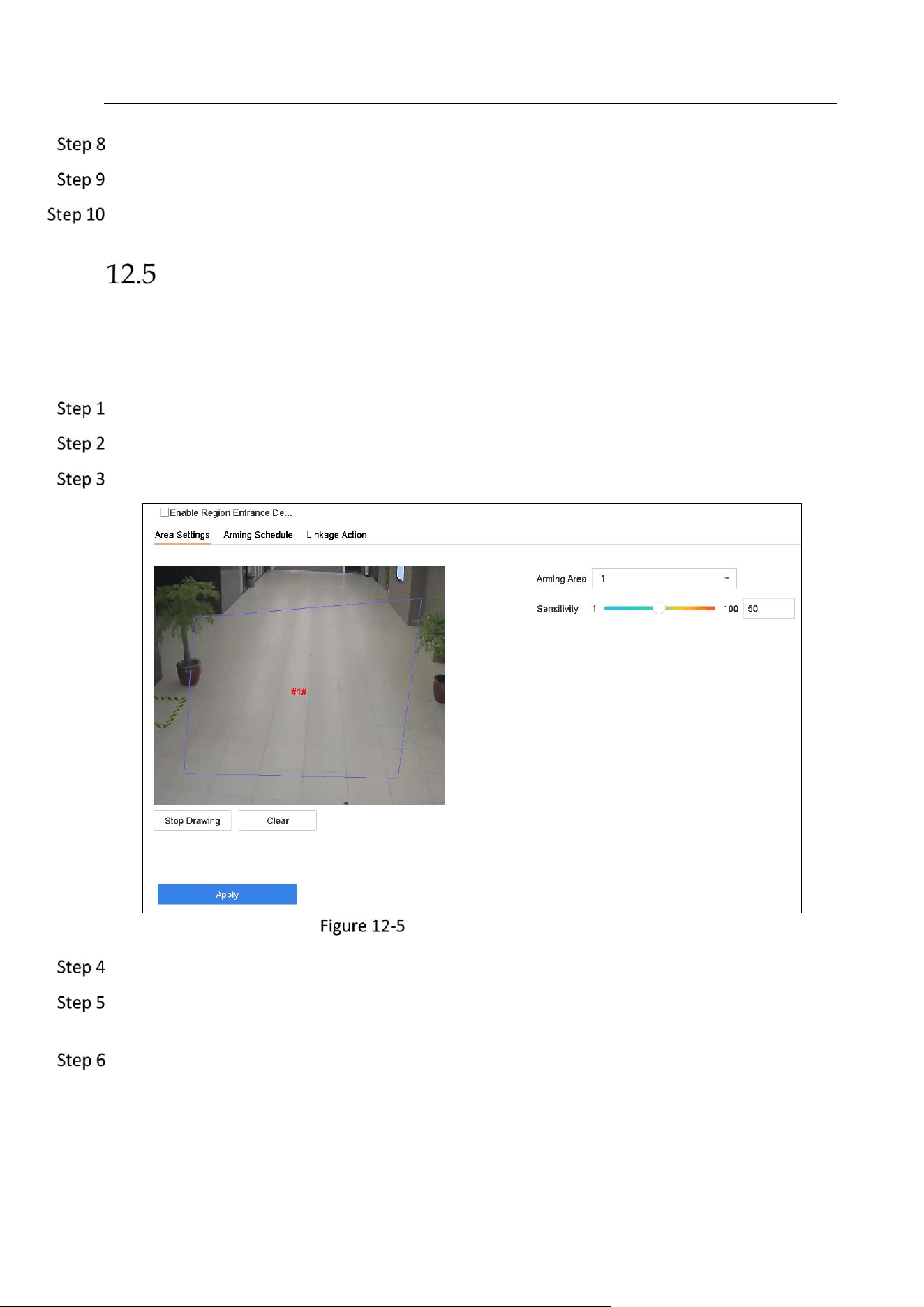
Network Video Recorder User Manual
126
Set the arming schedule. Refer to Chapter 11.1 Configure Arming Schedule.
Set the linkage actions. Refer to Chapter 11.2 Configure Alarm Linkage Actions.
Click Apply.
Region Entrance Detection
Purpose:
Region entrance detection function detects objects that enter a pre-defined virtual region from
the outside place.
Go to System Management > Event Settings > Smart Event.
Select a camera to configure.
Click the Region Entrance Detection item.
Region Entrance Detection
Check Enable Region Entrance Detection.
Optionally, check Save VCA Picture checkbox to save the captured pictures of region entrance
detection.
Follow the steps to set the detection rules and detection areas.
1) Select an Arming Region to configure. Up to 4 regions are selectable.
2) Drag the sliders to set Sensitivity.
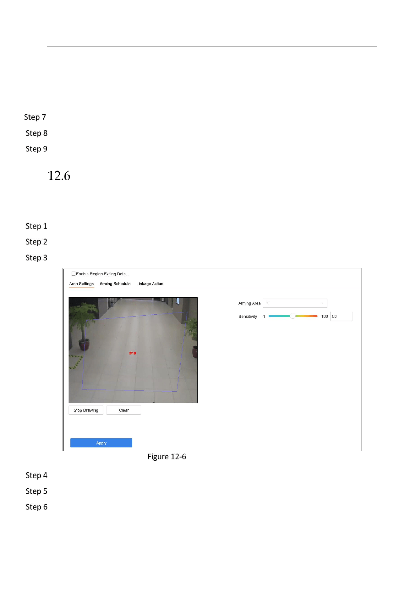
Network Video Recorder User Manual
127
Sensitivity: The higher the value is, the more easily the detection alarm can be triggered.
Its range is [0-100].
3) Click Draw Region and draw a quadrilateral in the preview window by specifying four
vertexes of the detection region.
Set the arming schedule. Refer to Chapter 11.1 Configure Arming Schedule.
Set the linkage actions. Refer to Chapter 11.2 Configure Alarm Linkage Actions.
Click Apply.
Region Exiting Detection
Purpose:
Region exiting detection function detects objects that exit from a pre-defined virtual region.
Go to System > Event > Smart Event.
Select a camera to configure.
Click Region Exiting.
Region Exiting Detection
Check Enable Region Exiting Detection.
Optionally, check Save VCA Picture to save the captured pictures of region exiting detection.
Follow the steps to set the detection rules and detection areas.
1) Select an Arming Region to configure. Up to 4 regions are selectable.
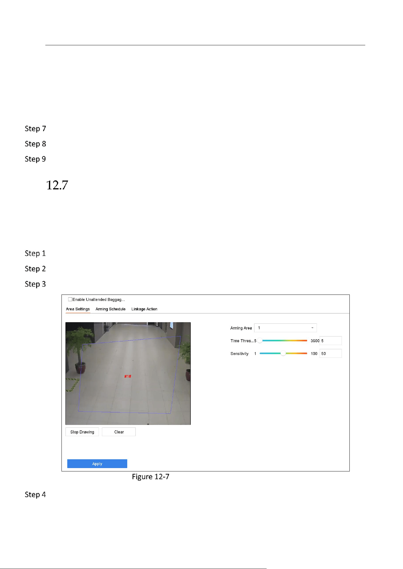
Network Video Recorder User Manual
128
2) Drag the sliders to set Sensitivity.
Sensitivity: The higher the value is, the more easily the detection alarm can be triggered.
Its range is [0-100].
3) Click Draw Region and draw a quadrilateral in the preview window by specifying four
vertexes of the detection region.
Set the arming schedule. Refer to Chapter 11.1 Configure Arming Schedule.
Set the linkage actions. Refer to Chapter 11.2 Configure Alarm Linkage Actions.
Click Apply.
Unattended Baggage Detection
Purpose:
Unattended baggage detection function detects the objects left over in the pre-defined region
such as the baggage, purse, dangerous materials, etc., and a series of actions can be taken when
the alarm is triggered.
Go to System > Event > Smart Event.
Select a camera to configure.
Click Unattended Baggage.
Unattended Baggage Detection
Check Enable Unattended Baggage Detection.

Network Video Recorder User Manual
129
Optionally, check Save VCA Picture to save the captured pictures of unattended baggage
detection.
Follow the steps to set the detection rules and detection areas.
1) Select an Arming Region to configure. Up to 4 regions are selectable.
2) Drag the sliders to set Time Threshold and Sensitivity.
Time Threshold: The time of the objects left over in the region. If the value is 10, alarm is
triggered after the object is left and stayed in the region for 10s. Its range is [5s-20s].
Sensitivity: Similarity degree of the background image. The higher the value is, the more
easily the detection alarm can be triggered.
3) Click Draw Region and draw a quadrilateral in the preview window by specifying four
vertexes of the detection region.
Set the arming schedule. Refer to Chapter 11.1 Configure Arming Schedule.
Set the linkage actions. Refer to Chapter 11.2 Configure Alarm Linkage Actions.
Click Apply.
Object Removal Detection
Purpose:
Object removal detection function detects the objects removed from the pre-defined region,
such as the exhibits on display, and a series of actions can be taken when the alarm is triggered.
Go to System > Event > Smart Event.
Select a camera to configure.
Click Object Removable.
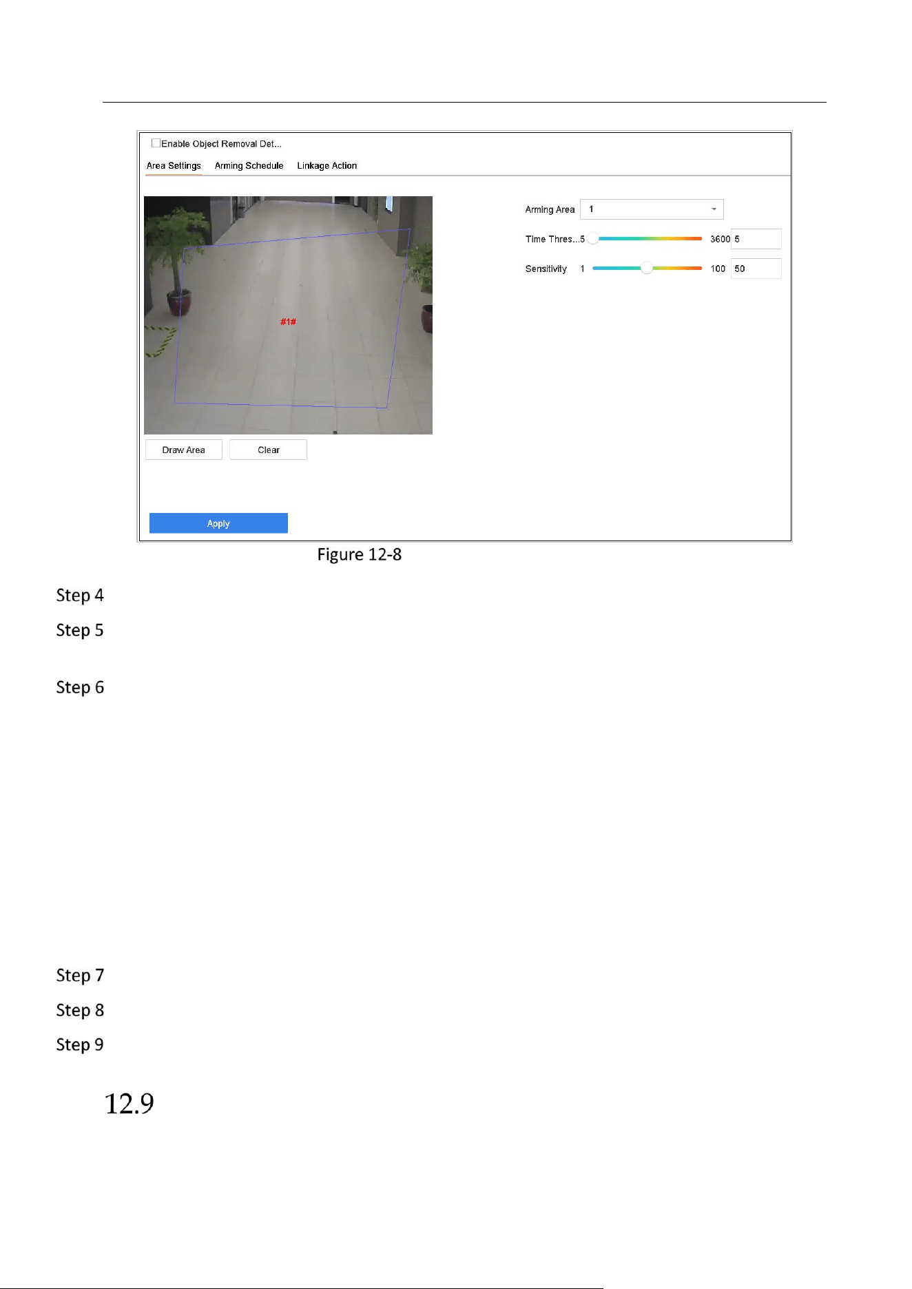
Network Video Recorder User Manual
130
Object Removal Detection
Check Enable Object Removable Detection.
Optionally, check Save VCA Picture to save the captured pictures of object removable
detection.
Follow the steps to set the detection rules and detection areas.
1) Select an Arming Region to configure. Up to 4 regions are selectable.
2) Drag the sliders to set Time Threshold and Sensitivity.
Time Threshold: The time of the objects removed from the region. If the value is 10,
alarm is triggered after the object disappeared from the region for 10s. Its range is [5s-
20s].
Sensitivity: The similarity degree of the background image. Usually, when the sensitivity is
high, a very small object taken from the region can trigger the alarm.
3) Click Draw Region and draw a quadrilateral in the preview window by specifying four
vertexes of the detection region.
Set the arming schedule. Refer to Chapter 11.1 Configure Arming Schedule.
Set the linkage actions. Refer to Chapter 11.2 Configure Alarm Linkage Actions.
Click Apply.
Audio Exception Detection
Purpose:
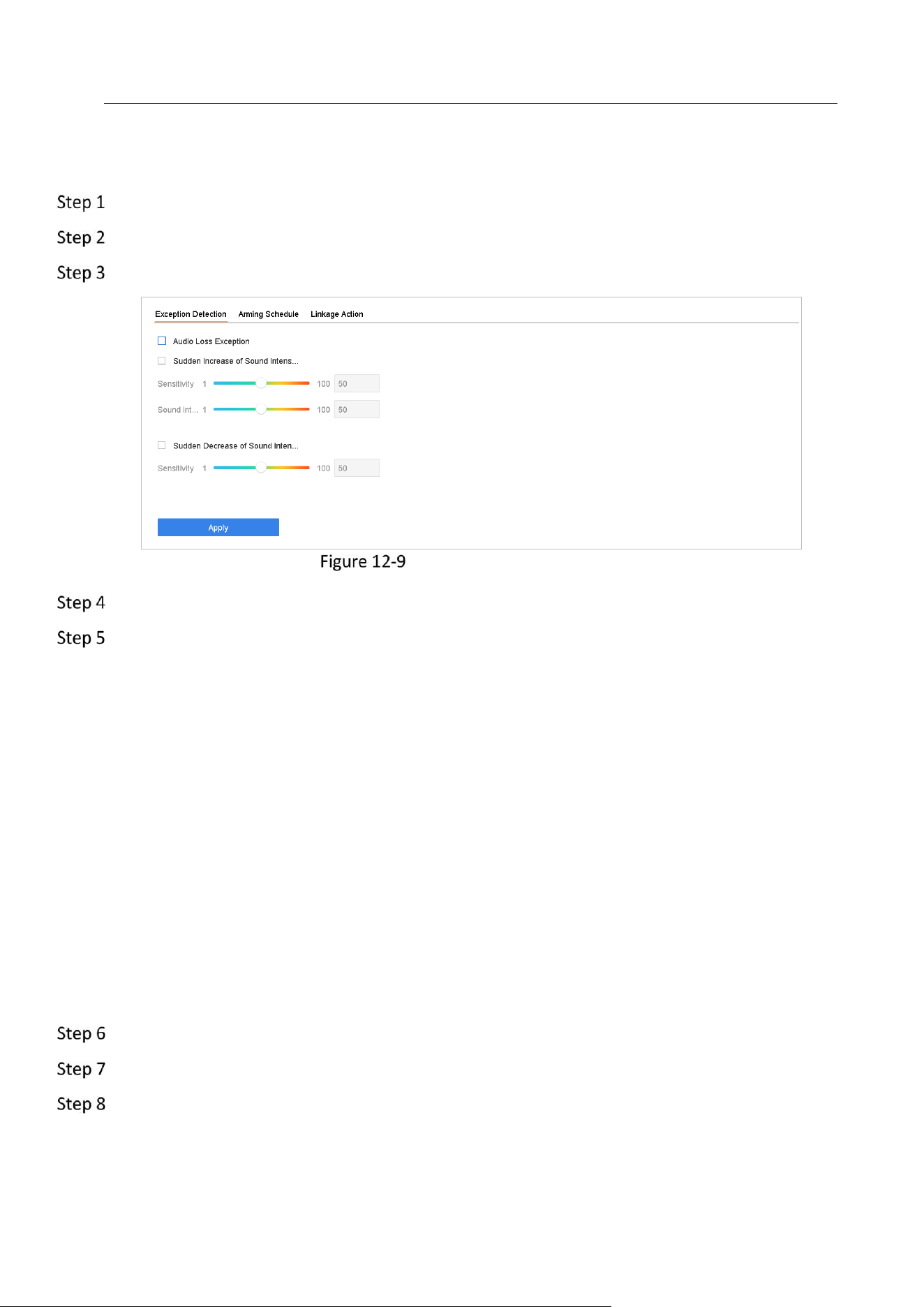
Network Video Recorder User Manual
131
Audio exception detection detects the abnormal sounds in the scene, such as the sudden
increase/decrease of the sound intensity.
Go to System > Event > Smart Event.
Select a camera to configure.
Click Audio Exception.
Audio Exception Detection
Optionally, check Save VCA Picture to save the captured pictures of audio exception detection.
Follow the steps to set the detection rules.
1) Select the Exception Detection tab.
2) Check the checkboxes of Audio Loss Exception, Sudden Increase of Sound Intensity
Detection, or Sudden Decrease of Sound Intensity Detection.
Audio Loss Exception: Detects the sound steep rise in the scene. You can set the
detection sensitivity and threshold for sound steep rise. You need to configure its
Sensitivity and Sound Intensity Threshold.
Sensitivity: The smaller the value is, the more severe the change should be to trigger the
detection. Range [1-100].
Sound Intensity Threshold: It can filter the sound in the environment. The louder the
environment sound, the higher the value should be. Adjust it according to the
environment. Range [1-100].
Sudden Decrease of Sound Intensity Detection: Detects the sound steep drop in the
scene. You need set the detection sensitivity [1-100].
Set the arming schedule. Refer to Chapter 11.1 Configure Arming Schedule.
Set the linkage actions. Refer to Chapter 11.2 Configure Alarm Linkage Actions.
Click Apply.
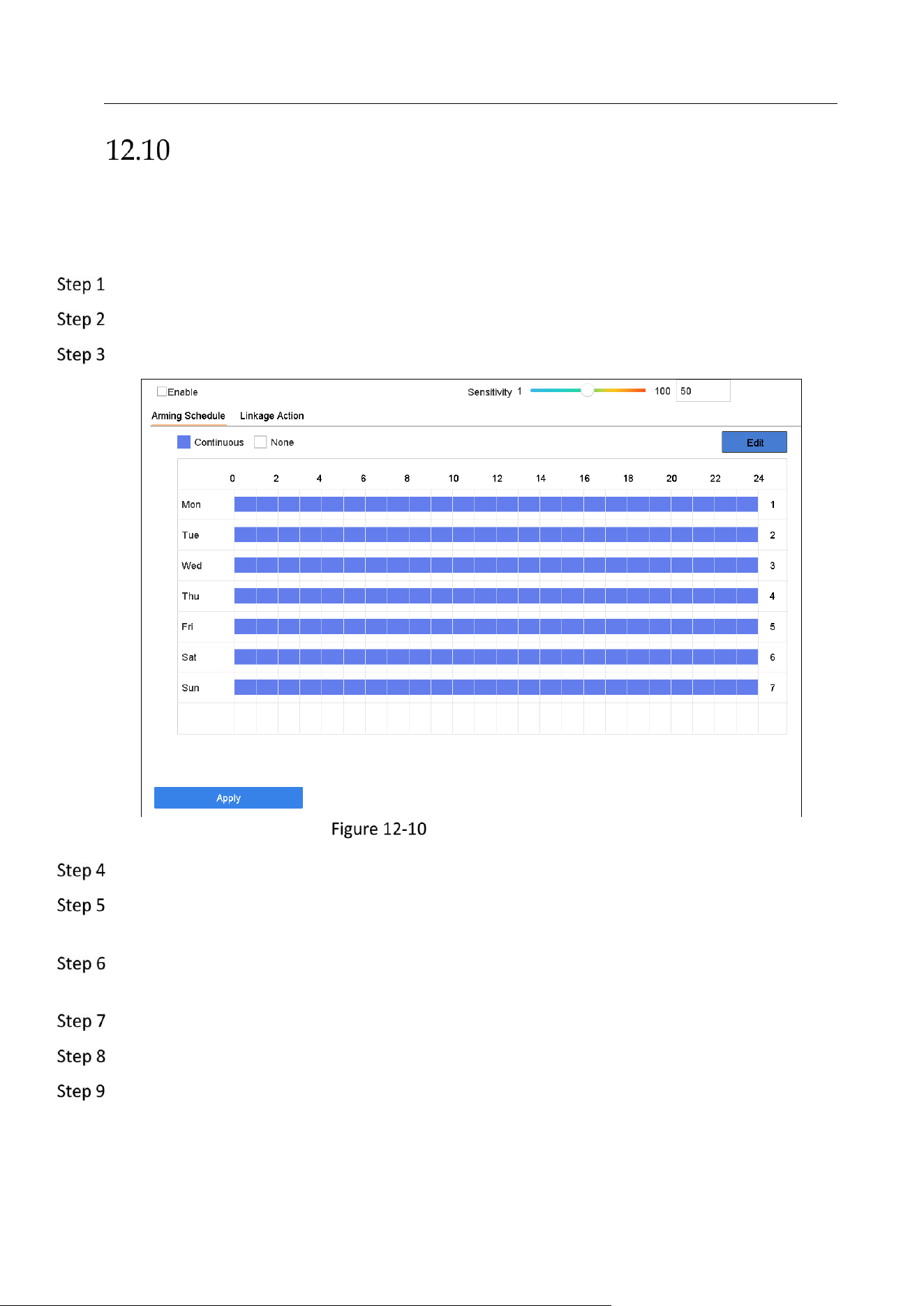
Network Video Recorder User Manual
132
Sudden Scene Change Detection
Purpose:
Scene change detection detects the change of environment affected by the external factors,
such as the intentional rotation of the camera.
Go to System > Event > Smart Event.
Select a camera to configure.
Click Sudden Scene Change.
Sudden Scene Change
Check Enable Sudden Scene Change Detection.
Optionally, check Save VCA Picture to save the captured pictures of sudden scene change
detection.
Drag the Sensitivity slider to set the detection sensitivity. Sensitivity range: [1-100]. The higher
the value is, the more easily the change of scene can trigger the alarm.
Set the arming schedule. Refer to Chapter 11.1 Configure Arming Schedule.
Set the linkage actions. Refer to Chapter 11.2 Configure Alarm Linkage Actions.
Click Apply.
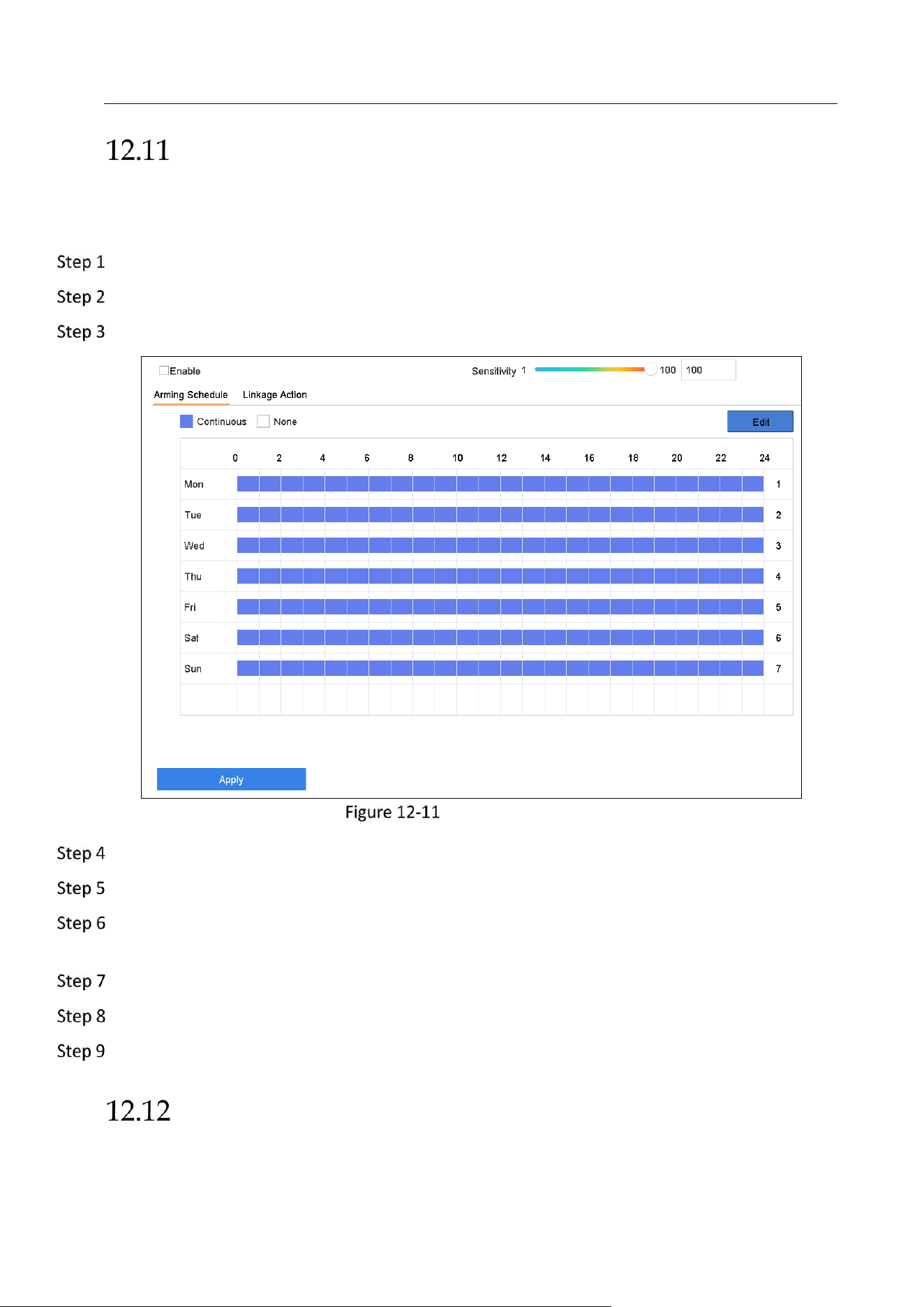
Network Video Recorder User Manual
133
Defocus Detection
Purpose:
The image blur caused by defocus of the lens can be detected.
Go to System > Event > Smart Event.
Select a camera to configure.
Click Defocus.
Defocus Detection
Check Enable Defocus Detection.
Optionally, check Save VCA Picture to save the captured pictures of defocus detection.
Drag the Sensitivity slider to set the detection sensitivity. Sensitivity range: [1-100]. The higher
the value is, the more easily the defocus image can be detected.
Set the arming schedule. Refer to Chapter 11.1 Configure Arming Schedule.
Set the linkage actions. Refer to Chapter 11.2 Configure Alarm Linkage Actions.
Click Apply.
PIR Alarm
Purpose:
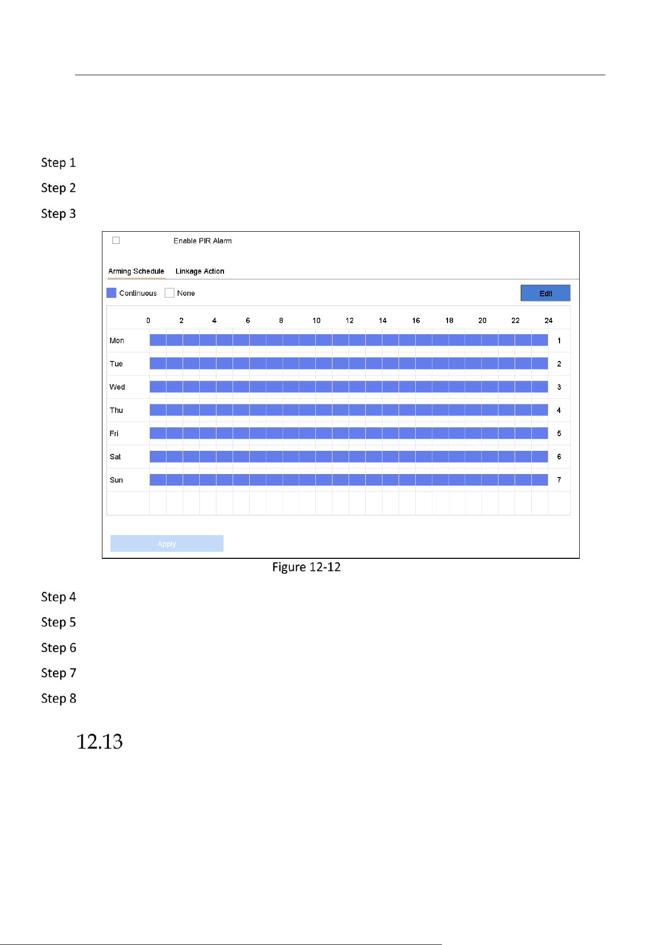
Network Video Recorder User Manual
134
A PIR (Passive Infrared) alarm is triggered when an intruder moves within the detector vision
field. The heat energy dissipated by a person, or any other warm blooded creature such as dogs,
cats, etc., can be detected.
Go to System > Event > Smart Event.
Select a camera to configure.
Click PIR Alarm.
FIR Alarm
Check Enable PIR Alarm.
Optionally, check Save VCA Picture to save the captured pictures of PIR alarm.
Set the arming schedule. Refer to Chapter 11.1 Configure Arming Schedule.
Set the linkage actions. Refer to Chapter 11.2 Configure Alarm Linkage Actions.
Click Apply.
Thermal Camera Detection
The NVR supports the event detection modes of the thermal network cameras: fire and smoke
detection, temperature detection, temperature difference detection, etc.
Before you start
Add the thermal network camera to your device and make sure the camera is activated.

Network Video Recorder User Manual
135
Go to System > Event > Smart Event.
Select a thermal camera from the camera list.
(Optional) Check Save VCA Picture to save the captured pictures of detection.
Select an event detection (Temperature, etc.).
Set the arming schedule. Refer to Chapter 11.1 Configure Arming Schedule.
Set the linkage actions. Refer to Chapter 11.1 Configure Arming Schedule
Select the Arming Schedule tab.
Choose one day of a week and set the time segment. Up to eight time periods can be set within
each day.
Time periods shall not be repeated or overlapped.
Set Arming Schedule
Click Apply to save the settings.
Configure Alarm Linkage Actions.
Click Apply.
Queue Management
After connecting the device with queue management camera, you can set the arming schedule
and linkage action of queue management.
Before you start

Network Video Recorder User Manual
136
Ensure you have connected the device with queue management camera, and the camera is
online.
Go to System > Event > Smart Event.
Select a queue management camera from the camera list.
(Optional) Check Save VCA Picture to save the captured pictures of detection.
Set the arming schedule. Refer to Chapter 11.1 Configure Arming Schedule.
Set the linkage actions. Refer to Chapter 11.1 Configure Arming Schedule
Select the Arming Schedule tab.
Choose one day of a week and set the time segment. Up to eight time periods can be set within
each day.
Time periods shall not be repeated or overlapped.
Set Arming Schedule
Click Apply to save the settings.
Configure Alarm Linkage Actions.
Click Apply.
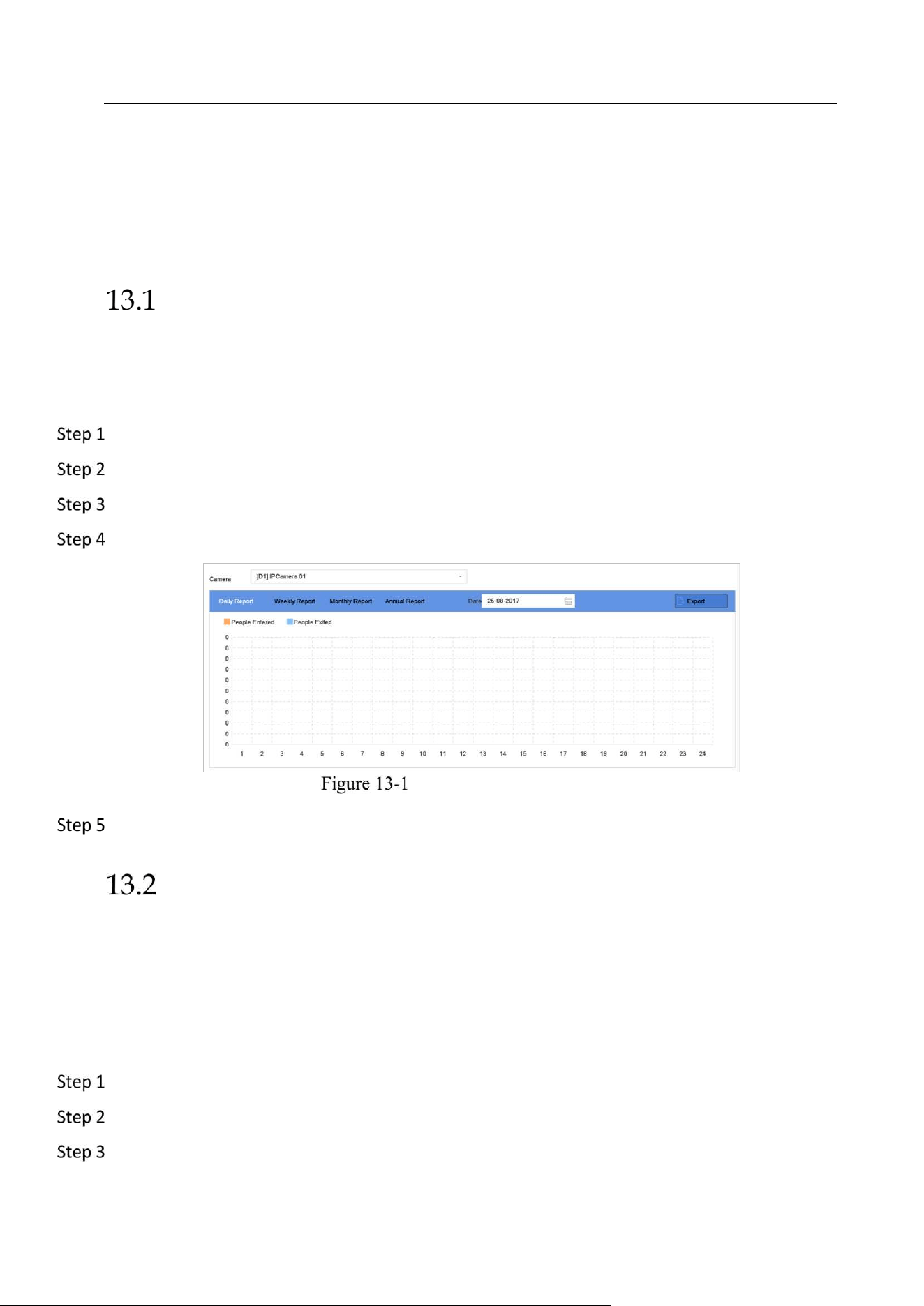
Network Video Recorder User Manual
137
Chapter 13 Smart Analysis
With the configured VCA detection, the device supports the smart analysis for people counting and
heat map.
People Counting
Purpose:
The Counting is used to calculate the number of people entered or left a certain configured area
and form in daily/weekly/monthly/annual reports for analysis.
Go to Smart Analysis > Counting.
Select the camera.
Select the report type to Daily Report, Weekly Report, Monthly Report, or Annual Report.
Set the Date to analyze. Then the people counting graphic will show.
People Counting Interface
(Optional) Click Export to export the report in excel format.
Heat Map
Purpose:
Heat map is a graphical representation of data. The heat map function is usually used to analyze
how many people visited and stayed in a specified area.
The heat map function must be supported by the connected IP camera and the corresponding
configuration must be set.
Go to Smart Analysis > Heat Map.
Select a camera.
Select the report type as Daily Report, Weekly Report, Monthly Report, or Annual Report.
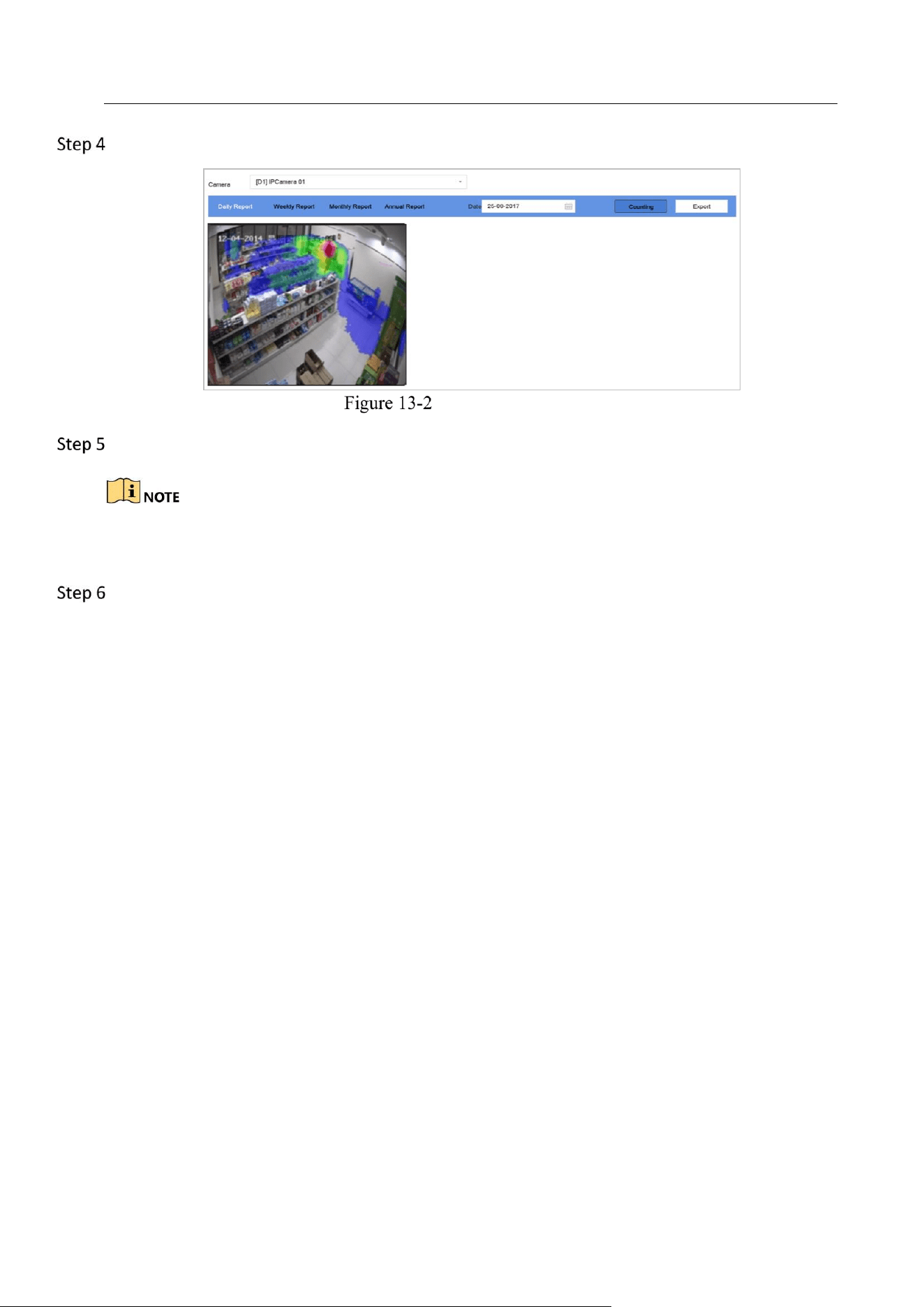
Network Video Recorder User Manual
138
Set the Data to analyze.
Heat Map Interface
Click Counting. Then the results displayed in graphics marked in different colors will show.
As shown in the figure above, red color block (255, 0, 0) indicates the most welcome area, and blue
color block (0, 0, 255) indicates the less-popular area.
(Optional) Click Export to export the statistics report in excel format.
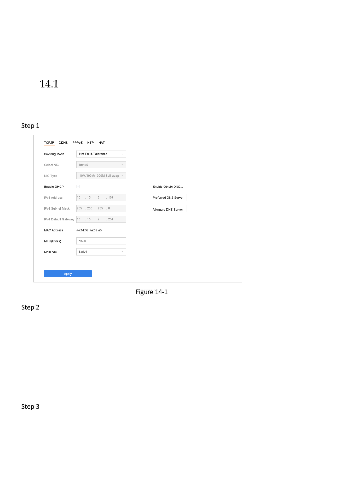
Network Video Recorder User Manual
139
Chapter 14 Network Settings
Configure TCP/IP Settings
Purpose
TCP/IP settings must be properly configured before you can operate the device over network.
Go to System > Network > TCP/IP.
TCP/IP Settings
Select Net-Fault Tolerance or Multi-Address Mode under Working Mode.
Net-Fault Tolerance: The two NIC cards use the same IP address, and you can select the main
NIC to LAN1 or LAN2. By this way, in case of one NIC card failure, the device will automatically
enable the other standby NIC card so as to ensure the normal running of the whole system.
Load Balance: By using the same IP address and two NIC cards share the load of the total
bandwidth, which enables the system to provide two Gigabit network capacity.
Multi-address Mode: The parameters of the two NIC cards can be configured independently.
You can select LAN1 or LAN2 under Select NIC for parameter settings. You can select one NIC
card as default route. And then the system is connecting with the extranet the data will be
forwarded through the default route.
Configure other IP settings as needed.

Network Video Recorder User Manual
140
Check Enable DHCP to obtain IP settings automatically if a DHCP server is available in the
network.
Valid range of MTU value is 500 to 9676.
Click Apply.
Configure Hik-Connect
Purpose
Hik-Connect provides mobile phone application and platform service to access and manage your
connected devices, which enables you to get a convenient remote access to the video security
system.
Go to System > Network > Advanced > Platform Access.
Check Enable to activate the function. Then the service terms will pop up.
1) Enter the verification code in Verification Code.
2) Scan the QR code to read the service terms and privacy statement.
3) Check The Hik-Connect service will require internet access. Please read Service Terms
and Privacy Statement before enabling the service if you agree the service terms and
privacy statement.
4) Click OK to save the settings.
Hik-Connect is disabled by default.
The verification code is empty by default. It must contain 6 to 12 letters or numbers, and it
is case sensitive.
(Optional) Check Custom to enter the server address as your desire.
(Optional) Check Enable Stream Encryption, verification code is required for remote access and
live view.
(Optional) Click Unbind if the device requires to unbind with the current Hik-Connect account.
Click Apply.
What to do next:
After configuration, you can access and manage your devices through Hik-Connect app or
website.
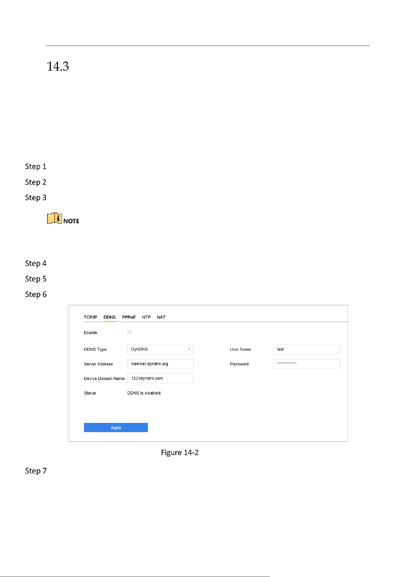
Network Video Recorder User Manual
141
Configure DDNS
Purpose
You can set Dynamic DNS service for network access. Different DDNS modes are available:
DynDNS, PeanutHull, and NO-IP.
Before You Start
You must register DynDNS, PeanutHull and NO-IP services with your ISP before configuring DDNS
settings.
Go to System > Network > TCP/IP > DDNS.
Check Enable.
Select DynDNS under DDNS Type.
PeanutHull and NO-IP are also available under DDNS Type, and required information should be
entered accordingly.
Enter Server Address for DynDNS (i.e. members.dyndns.org).
Under Device Domain Name, enter the domain name obtained from the DynDNS website.
Enter the User Name and Password registered in the DynDNS website.
DDNS Settings
Click Apply.
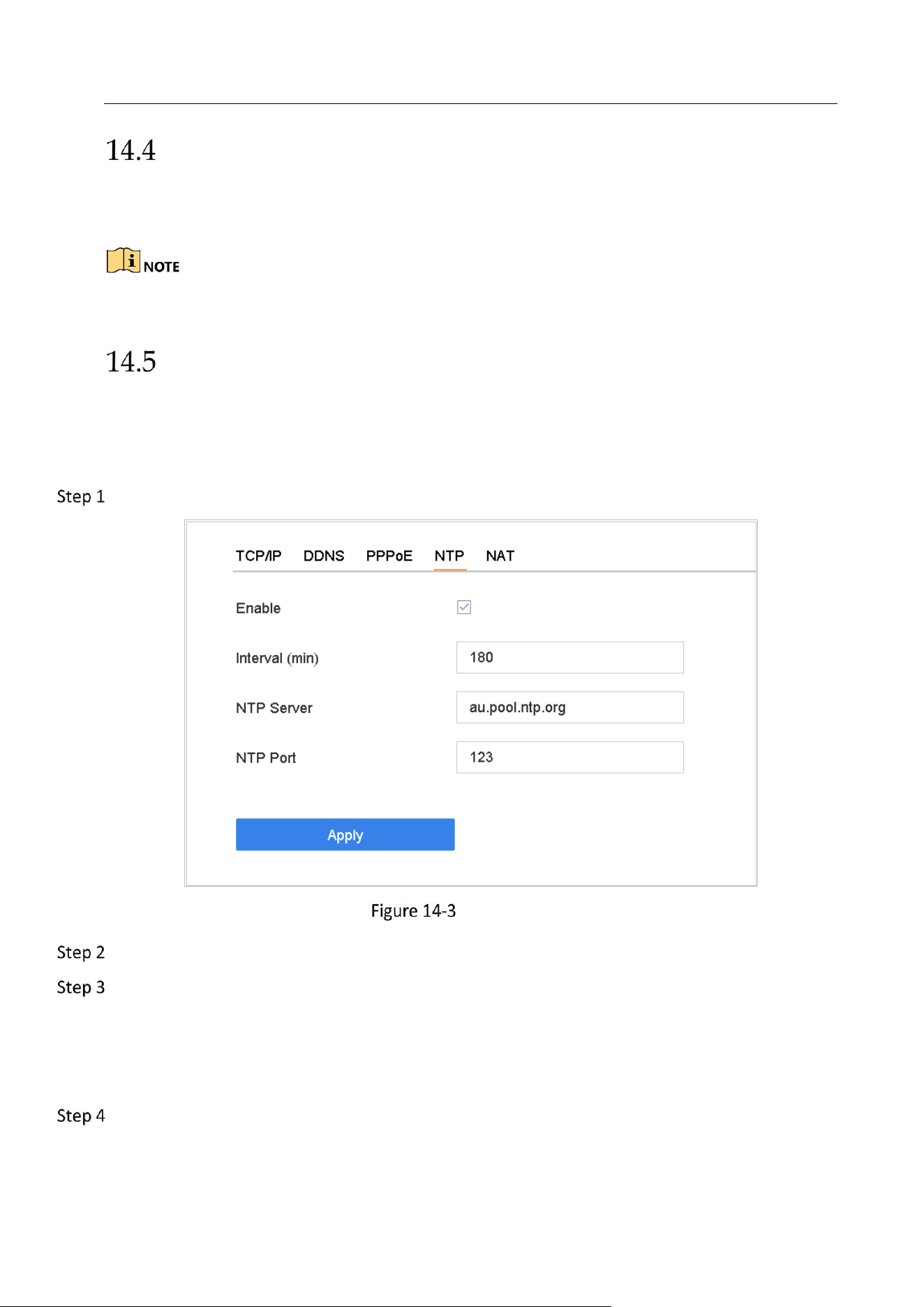
Network Video Recorder User Manual
142
Configure PPPoE
If the device is connected to Internet through PPPoE, you need to configure user name and
password accordingly under System > Network > TCP/IP > PPPoE.
Contact your Internet service provider for details about PPPoE service.
Configure NTP
Purpose
Connection to a network time protocol (NTP) server can be configured on your device to ensure
the accuracy of system date and time.
Go to System > Network > TCP/IP > NTP.
NTP Settings
Check Enable.
Configure NTP settings as need.
Interval (min): Time interval between two time synchronization with NTP server.
NTP Server: IP address of the NTP server.
NTP Port: Port of the NTP server.
Click Apply.
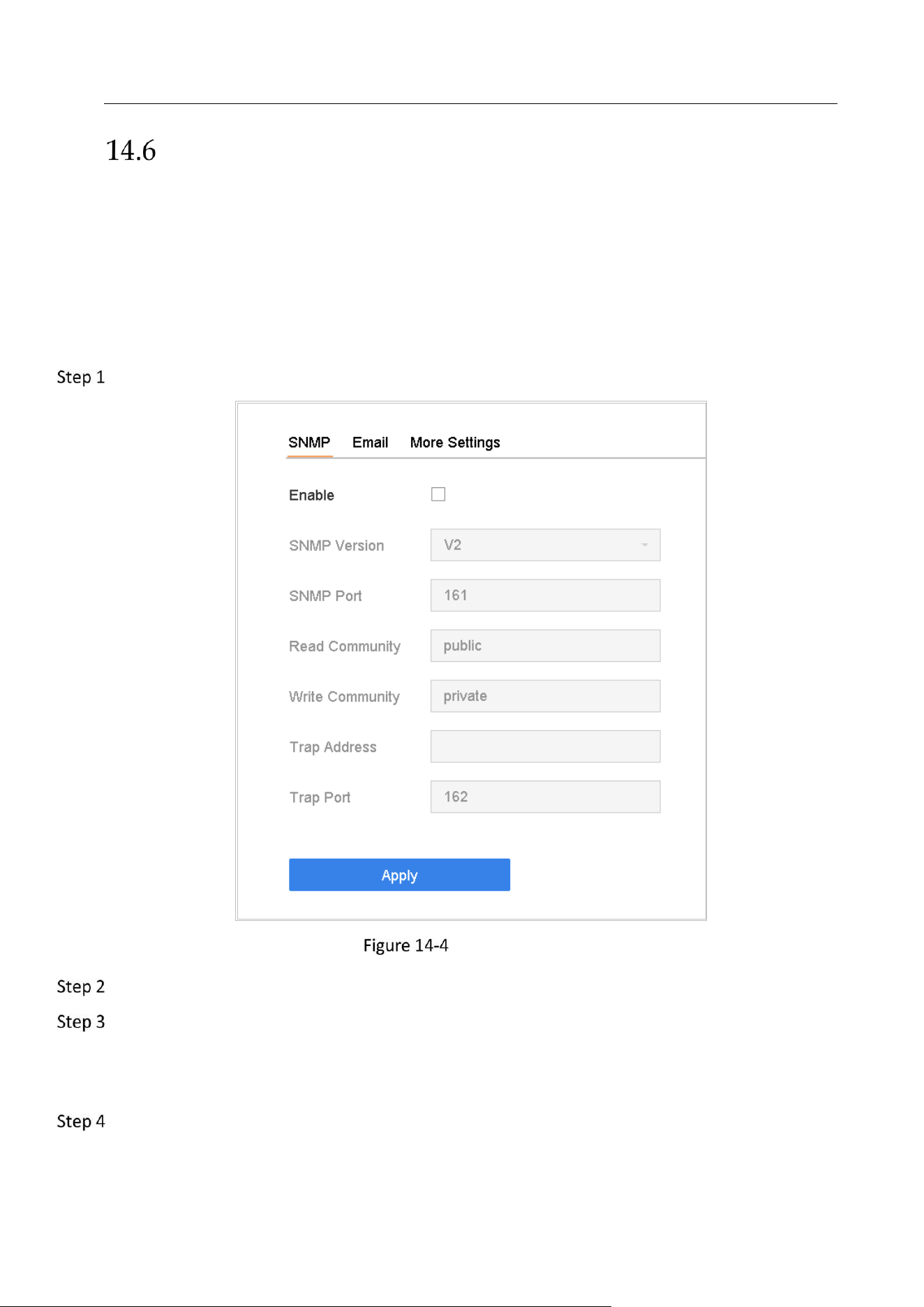
Network Video Recorder User Manual
143
Configure SNMP
Purpose
You can configure SNMP settings to get device status and parameter information.
Before You Start
Download the SNMP software to receive device information via SNMP port. By setting the trap
address and port, the device is allowed to send alarm event and exception message to the
center.
Go to System > Network > Advanced > SNMP.
SNMP Settings
Check Enable. A message will pop up to prompt possible security risk and click Yes to continue.
Configure the SNMP settings as needed.
Trap Address: IP address of the SNMP host.
Trap Port: Port of the SNMP host.
Click Apply.
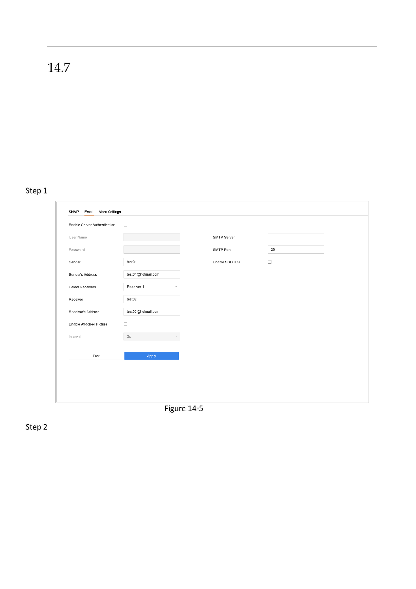
Network Video Recorder User Manual
144
Configure Email
Purpose
The system can be configured to send an Email notification to all designated users when a
specified event occur, such as an alarm or motion event is detected, or the administrator
password is changed, etc.
Before You Start
The device must be connected to a local area network (LAN) that contains an SMTP mail server.
The network must also be connected to either an intranet or the Internet depending on the
location of the e-mail accounts to which you want to send notification.
Go to System > Network > Advanced > Email.
Email Settings
Configure the following Email settings.
Enable Server Authentication: Check to enable the function if the SMTP server requires user
authentication and enter user name and password accordingly.
SMTP Server: The IP address of SMTP Server or host name (e.g., smtp.263xmail.com).
SMTP Port: The SMTP port. The default TCP/IP port used for SMTP is 25.
Enable SSL/TLS: Check to enable SSL/TLS if required by the SMTP server.
Sender: The name of the sender.
Sender's Address: Sender's Address.
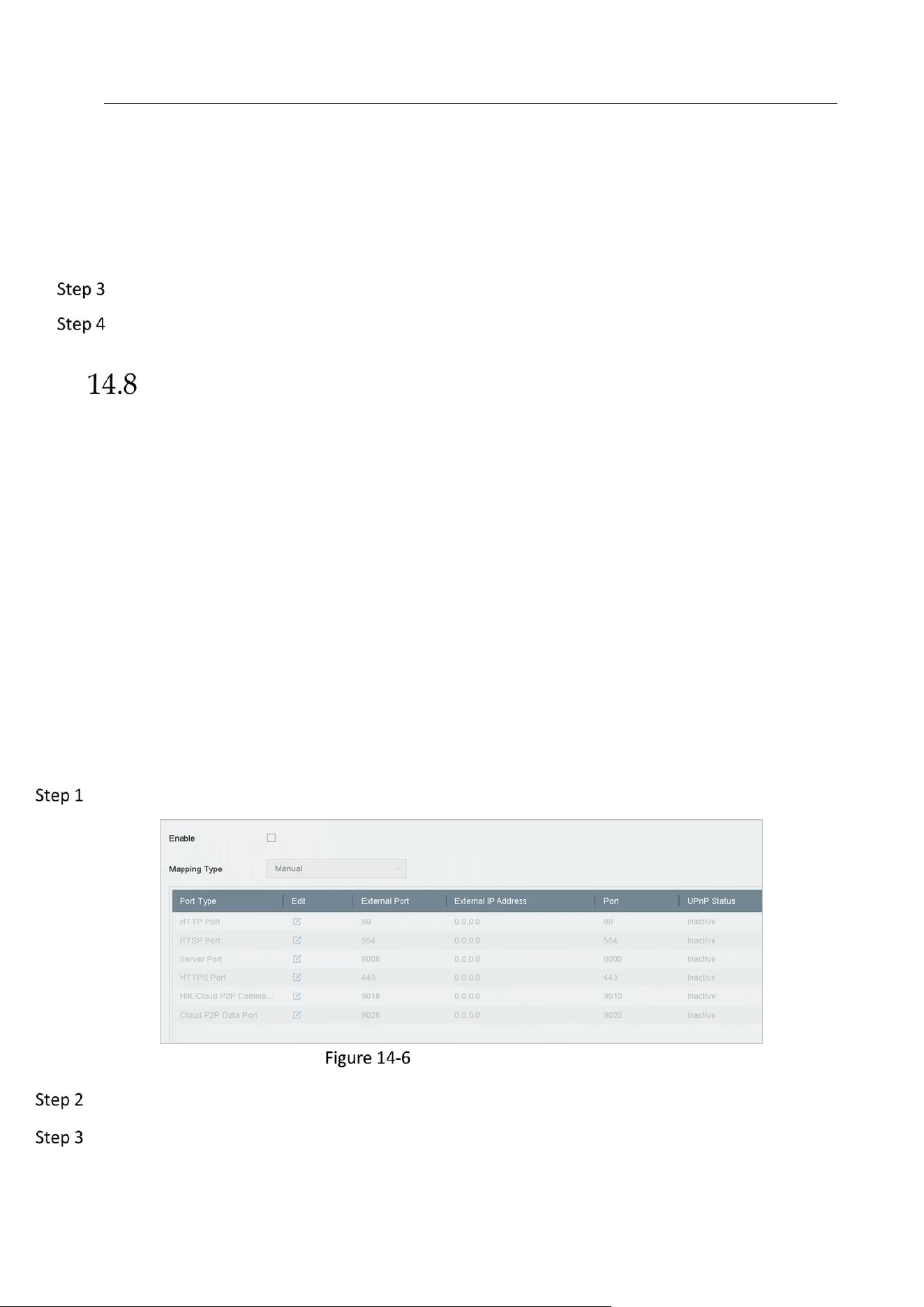
Network Video Recorder User Manual
145
Select Receivers: Select the receiver. Up to 3 receivers can be configured.
Receiver: The name of the receiver.
Receiver's Address: The Email address of user to be notified.
Enable Attached Picture: Check to enable the function if you want to send email with attached
alarm images. The interval is the time between two adjacent alarm images.
Click Apply.
(Optional) Click Test to send a test email.
Configuring NAT
Purpose:
Two ways are provided for port mapping to realize the remote access via the cross-segment
network, UPnP™ and manual mapping.
UPnP
TM
Universal Plug and Play (UPnP™) can permit the device seamlessly discover the presence of other
network devices on the network and establish functional network services for data sharing,
communications, etc. You can use the UPnP™ function to enable the fast connection of the device
to the WAN via a router without port mapping.
Before you start:
If you want to enable the UPnP™ function of the device, you must enable the UPnP™ function of
the router to which your device is connected. When the network working mode of the device is set
as multi-address, the Default Route of the device should be in the same network segment as that
of the LAN IP address of the router.
Go to Menu > Configuration > Network > NAT.
UPnP™ Settings Interface
Check Enable UPnP.
Select Mapping Type as Manual or Auto.
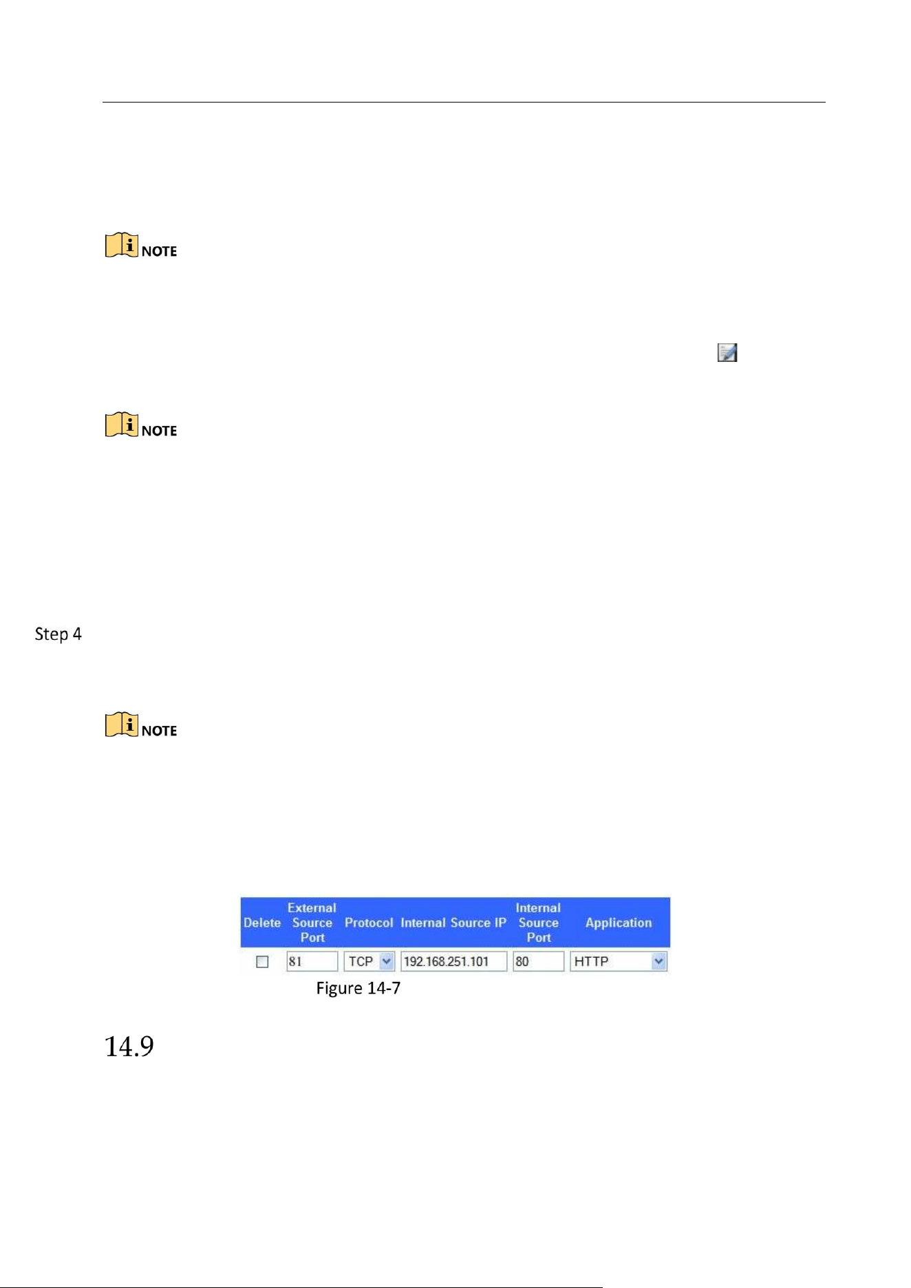
Network Video Recorder User Manual
146
OPTION 1: Auto
If you select Auto, the port mapping items are read-only, and the external ports are set by the
router automatically.
You can click Refresh to get the latest status of the port mapping.
OPTION 2: Manual
If you select Manual, you can edit the external port on your demand by clicking to
activate External Port Settings.
You can use the default port No., or change it according to actual requirements.
External Port indicates the port No. for port mapping in the router.
The value of the RTSP port No. should be 554 or between 1024 and 65535, while the value
of the other ports should be between 1 and 65535 and the value must be different from
each other. If multiple devices are configured for the UPnP™ settings under the same
router, the value of the port No. for each device should be unique.
Enter the virtual server setting page of router; fill in the blank of Internal Source Port with the
internal port value, the blank of External Source Port with the external port value, and other
required contents.
Each item should be corresponding with the device port, including server port, http port,
RTSP port and https port.
The virtual server setting interface below is for reference only, it may be different due to
different router manufactures. Please contact the manufacture of router if you have any
problems with setting virtual server.
Setting Virtual Server Item
Configure Ports
You can configure different types of ports to enable relevant functions.
Go to System > Network > Advanced > More Settings and configure port settings as needed.
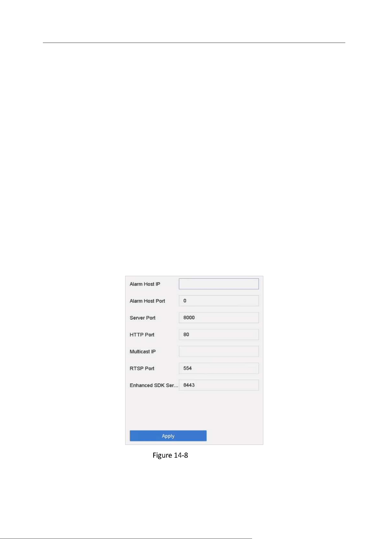
Network Video Recorder User Manual
147
Alarm Host IP/Port: With a remote alarm host configured, the device will send the alarm
event or exception message to the host when an alarm is triggered. The remote alarm host
must have the client management system (CMS) software installed.
The Alarm Host IP refers to the IP address of the remote PC on which the CMS software (e.g.,
iVMS-4200) is installed, and the Alarm Host Port (7200 by default) must be the same as the
alarm monitoring port configured in the software.
Server Port: Server port (8000 by default) should be configured for remote client software
access and its valid range is 2000 to 65535.
HTTP Port: HTTP port (80 by default) should be configured for remote web browser access.
Multicast IP: Multicast can be configured to enable live view for cameras that exceed the
maximum number allowed through network. A multicast IP address covers Class-D IP ranging
from 224.0.0.0 to 239.255.255.255 and it is recommended to use the IP address ranging from
239.252.0.0 to 239.255.255.255.
When adding a device to the CMS software, the multicast address must be the same as that of
the device.
RTSP Port: RTSP (Real Time Streaming Protocol) is a network control protocol designed for use
in entertainment and communications systems to control streaming media servers. The port is
554 by default.
Enhanced SDK Service Port: The enhanced SDK service adopts TLS protocol over the SDK
service that provides safer data transmission. The port is 8443 by default.
Port Settings
Network Video Recorder User Manual
148
Chapter 15 Hot Spare Device Backup
Purpose:
The device can form an N+1 hot spare system. The system consists of several working devices
and a hot spare device; when the working device fails, the hot spare device switches into
operation, thus increasing the reliability of the system. Please contact dealer for details of
models which support the hot spare function.
A bidirectional connection shown in the figure below is required to be built between the hot
spare device and each working device.
Set a hot spare
device
Add a hot spare
device on normal
device
Add the normal
device on the hot
spare device
Start
Finish
Building Hot Spare System
Before you start:
At least 2 devices are online.
Set Hot Spare Device
Purpose:
Hot spare devices takes over working device tasks when working device fails.
Go to System > Hot Spare.
Set the Work Mode as Hot Spare Mode.
Hot Spare
Click Apply.
Click Yes in popup attention box to reboot the device.
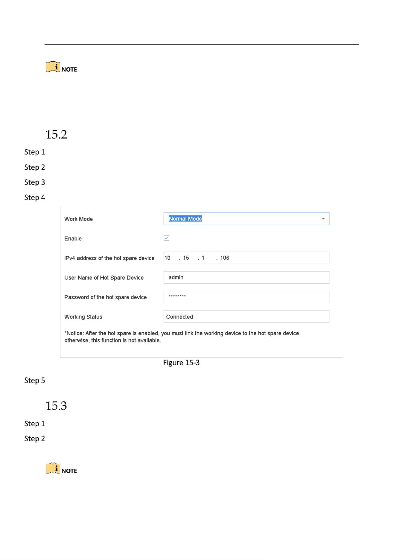
Network Video Recorder User Manual
149
The camera connection will be disabled when the device works in the hot spare mode.
It is highly recommended to restore the defaults of the device after switching the working
mode of the hot spare device to normal mode to ensure the normal operation afterwards.
Set Working Device
Go to System > Hot Spare.
Set the Work Mode as Normal Mode.
Check Enable.
Enter the IP address, user name, and password of hot spare device.
Hot Spare
Click Apply.
Manage Hot Spare System
Go to System > Hot Spare in hot spare device.
Check working devices from the device list and click Add to link the working device to the hot
spare device.
A hot spare device can connect up to 32 working devices.

Network Video Recorder User Manual
150
Working Status Descrption
Working
Status
Description
No record
The working device works properly.
Backing up
The working device gets offline, the hot spare device will record the
video of the IP camera connected to the working device for backup
The record backing up can be functioned for 1 working device at a time.
Synchronizing
The working device comes online, the lost video files will be restored
by the record synchronization function.
The record synchronization function can be enabled for 1 working
device at a time.
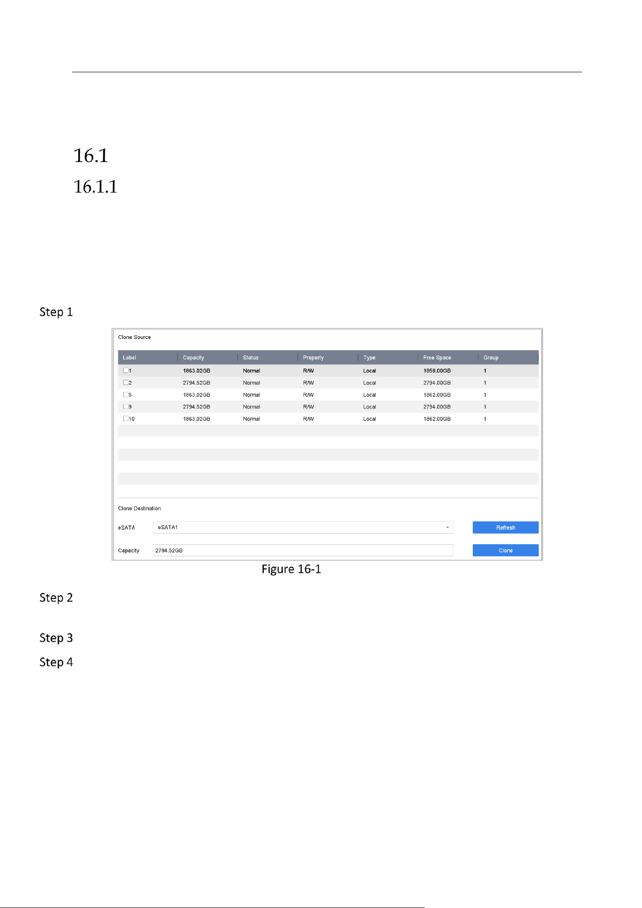
Network Video Recorder User Manual
151
Chapter 16 System Maintenance
Storage Device Maintenance
Configure Disk Clone
Purpose:
Select the HDDs to clone to eSATA HDD.
Before you start:
Connect an eSATA disk to the device.
Go to Maintenance > HDD Operation > HDD Clone.
HDD Clone
Check the HDD to clone. The capacity of selected HDD must match the capacity of clone
destination.
Click Clone.
Click Yes on popup message box to continue clone.
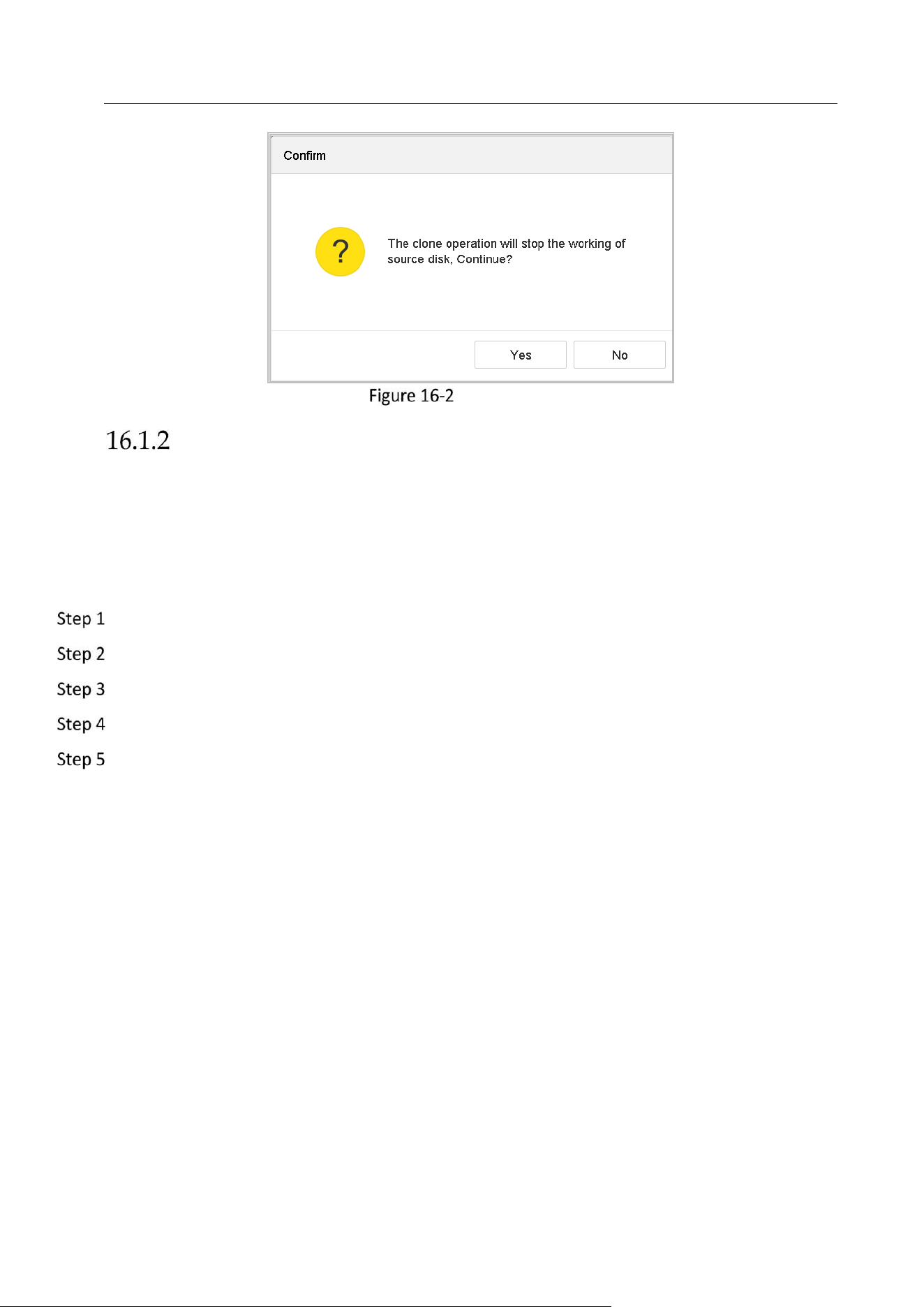
Network Video Recorder User Manual
152
Message Box
S.M.A.R.T Detection
Purpose:
The device provides the HDD detection function such as the adopting of the S.M.A.R.T. and the
Bad Sector Detection technique. The S.M.A.R.T. (Self-Monitoring, Analysis and Reporting
Technology) is a monitoring system for HDD to detect and report on various indicators of
reliability in the hopes of anticipating failures.
Go to Maintenance > HDD Operation > S.M.A.R.T..
Select the HDD to view its S.M.A.R.T information list.
Select the self-test types as Short Test, Expanded Test or the Conveyance Test.
Click Self-Test to start the S.M.A.R.T. HDD self-evaluation.
The related information of the S.M.A.R.T. is shown on the interface. You can check the HDD
status.
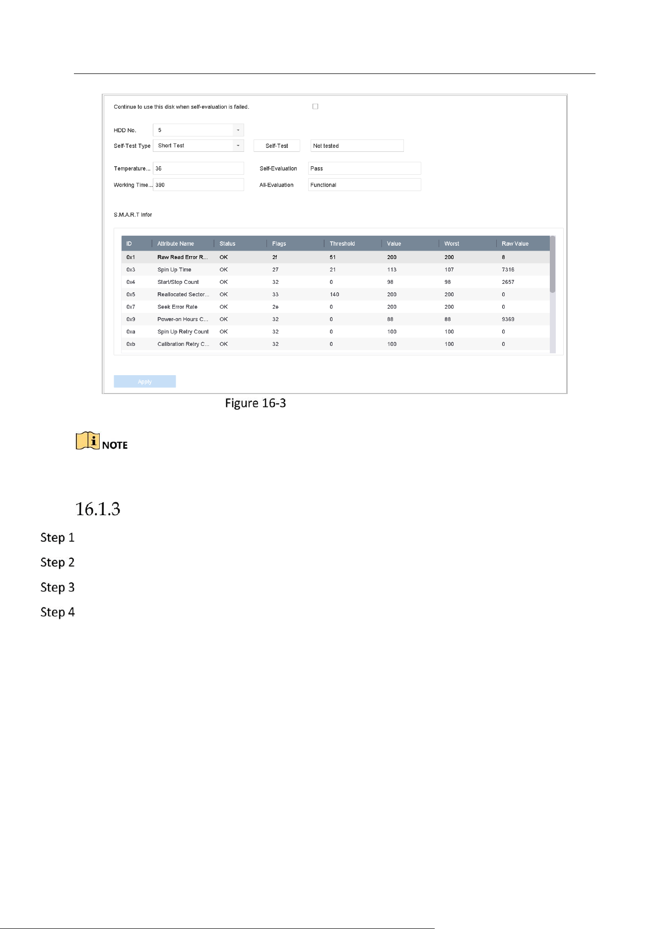
Network Video Recorder User Manual
153
S.M.A.R.T Settings Interface
If you want to use the HDD even when the S.M.A.R.T. checking is failed, you can check the
checkbox of the Continue to use the disk when self-evaluation is failed item.
Bad Sector Detection
Go to Maintenance > HDD Operation > Bad Sector Detection.
Select the HDD No. in the dropdown list you want to configure.
Select All Detection or Key Area Detection as the detection type.
Click the Self-Test button to start the detection.
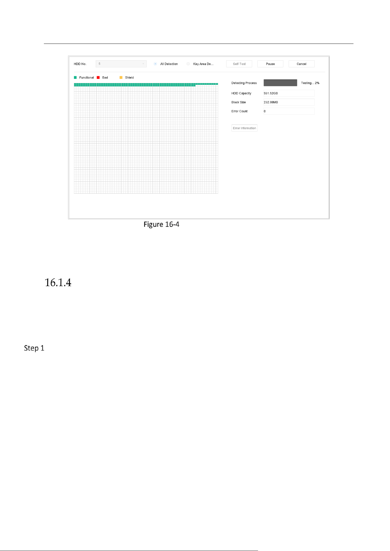
Network Video Recorder User Manual
154
Bad Sector Detection
You can also pause/resume or cancel the detection.
After testing completed, you can click Error information button to see the detailed damage
information.
HDD Health Detection
Purpose:
You can view the health status of Seagate HDD that generated after October 1th, 2017 and
capacity ranges from 4 TB to 8 TB. The function helps you to troubleshoot HDD problems.
Compared with S.M.A.R.T function, health detection shows HDD status with more details.
Go to Maintenance > HDD Operation > Health Detection.
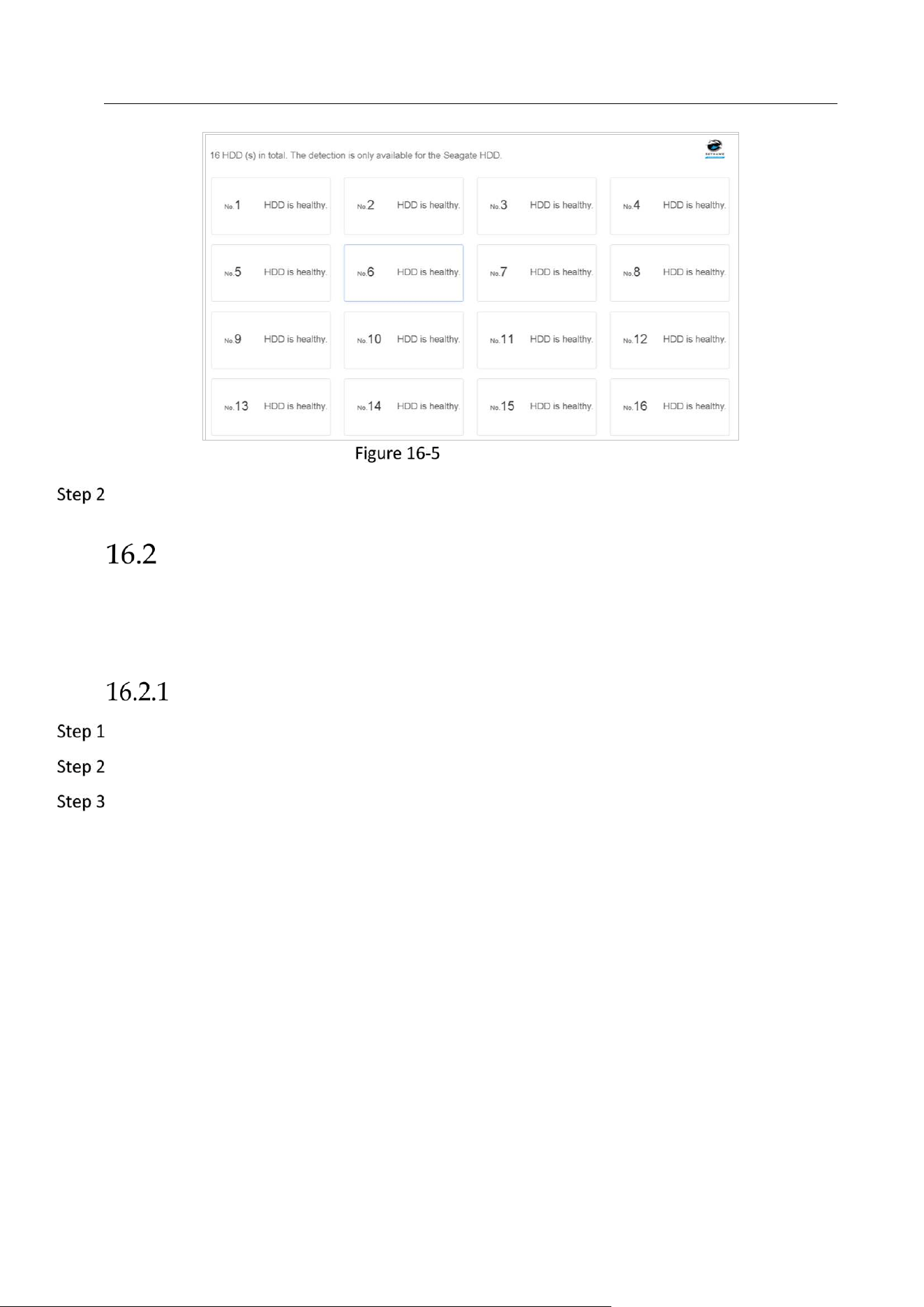
Network Video Recorder User Manual
155
Health Detection
Click a HDD to view details.
Search & Export Log Files
Purpose:
The operation, alarm, exception and information of the device can be stored in log files, which
can be viewed and exported at any time.
Search the Log Files
Go to Maintenance > Log Information.
Set the log search conditions, including the Time, Major Type and Minor Type.
Click Search to start search log files.
The matched log files will be displayed on the list shown below.
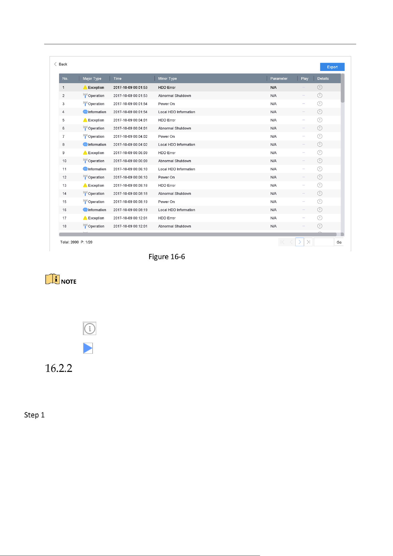
Network Video Recorder User Manual
156
Log Search Results
Up to 4000 log files can be displayed each time.
Related Operation:
Click the button or double click it to view its detailed information.
Click the button to view the related video file.
Export the Log Files
Before You Start:
Connect a storage device to your device.
Search the log files. Refer to Chapter 16.2.1 Search the Log Files.
Click Export to export the result log files of searching. Or you can click Export ALL on the Log
Search interface to export all the system logs to the storage device.
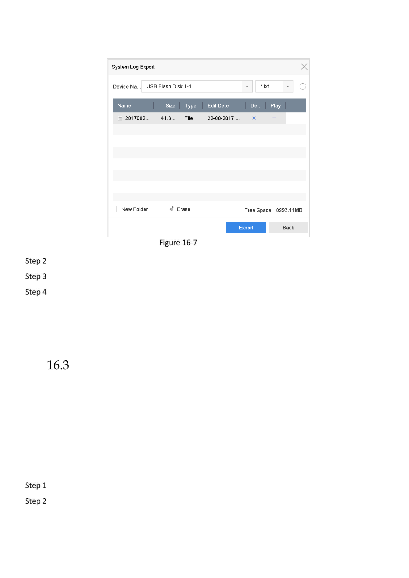
Network Video Recorder User Manual
157
Export Log Files
On the Export interface, select the storage device from the dropdown list of Device Name.
Select the format of the log files to be exported. Up to 15 formats are selectable.
Click the Export to export the log files to the selected storage device.
Related Operation:
Click the New Folder button to create new folder in the storage device.
Click the Format button to format the storage device before log export.
Import/Export IP Camera Configuration Files
Purpose:
The information of added IP camera can be generated into an excel file and exported to the local
device for backup, including the IP address, manage port, password of admin, etc. And the
exported file can be edited on your PC, like adding or deleting the content, and copy the setting
to other devices by importing the excel file to it.
Before You Start:
Connect a storage device to your device. For importing the configuration file, the storage device
must be with the file.
Go to Camera > IP Camera Import/Export.
Click the IP Camera Import/Export tab, and the content of detected plugged external device
appears.

Network Video Recorder User Manual
158
Export or import the IP camera configuration files.
Click Export to export configuration files to the selected local backup device.
To import a configuration file, select the file from the selected backup device and click the
Import button.
After the importing process is completed, you must reboot the device to activate the settings.
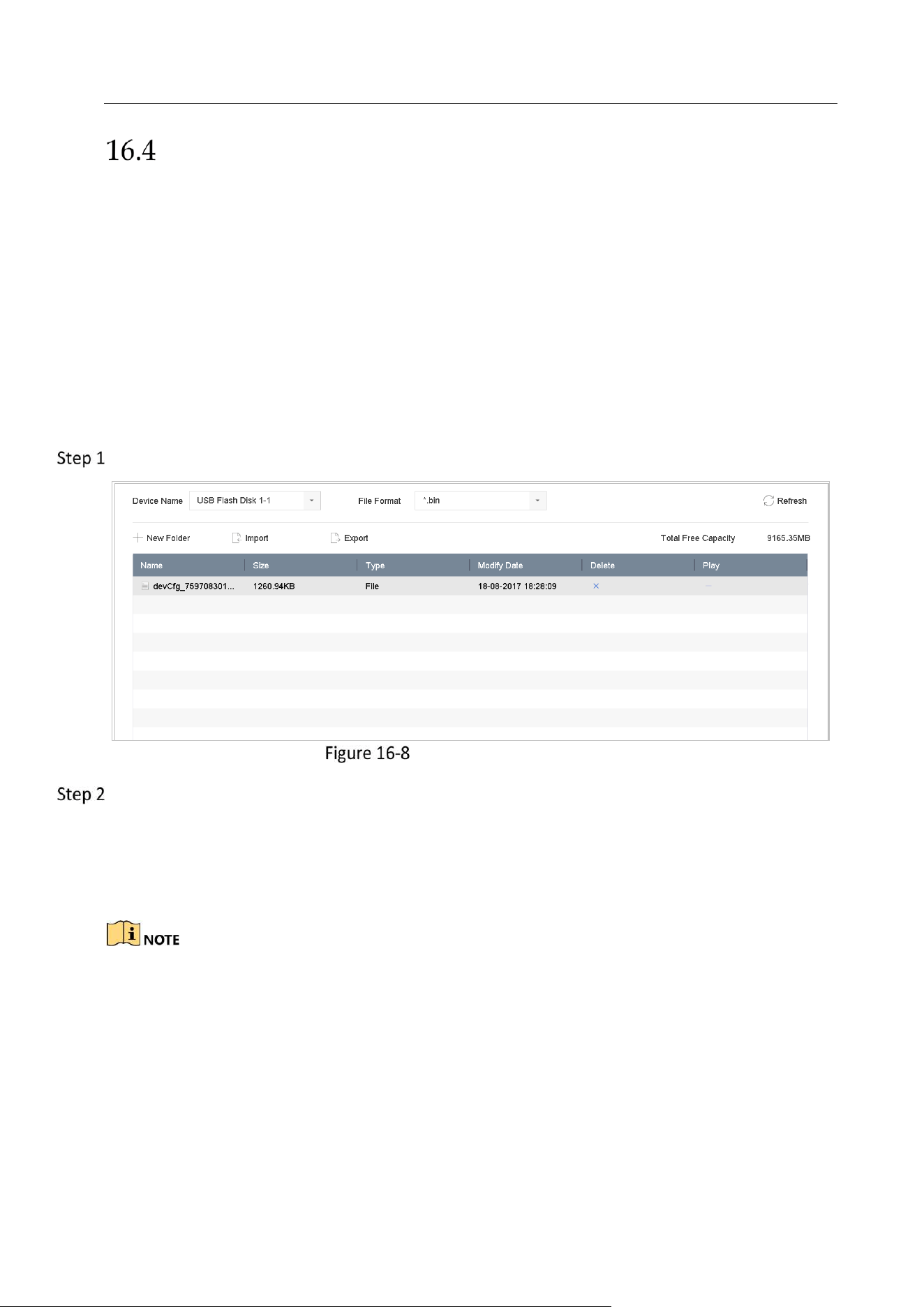
Network Video Recorder User Manual
159
Import/Export Device Configuration Files
Purpose:
The configuration files of the device can be exported to local device for backup; and the
configuration files of one device can be imported to multiple devices if they are to be configured
with the same parameters.
Connect a storage device to your device. For importing the configuration file, the storage device
must be with the file.
Before You Start:
Connect a storage device to your device. For importing the configuration file, the storage device
must be with the file.
Go to Maintenance >Import/Export.
Import/Export Config File
Export or import the device configuration files.
Click Export to export configuration files to the selected local backup device.
To import a configuration file, select the file from the selected backup device and click the
Import button.
After having finished the import of configuration files, the device will reboot automatically.
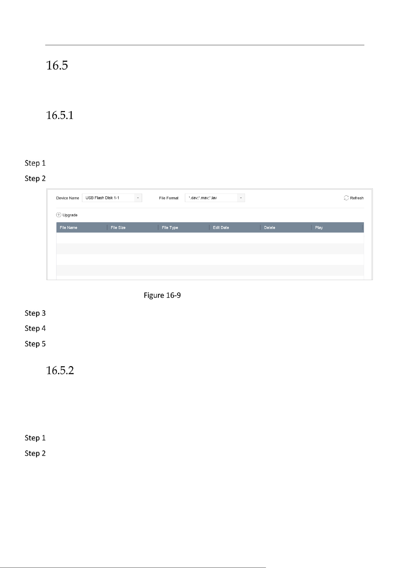
Network Video Recorder User Manual
160
Upgrade System
Purpose:
The firmware on your device can be upgraded by local backup device or remote FTP server.
Upgrade by Local Backup Device
Before You Start:
Connect your device with a local storage device with update firmware file.
Go to Maintenance>Upgrade.
Click the Local Upgrade tab to enter the local upgrade interface.
Local Upgrade Interface
Select the update file from the storage device.
Click Upgrade to start upgrading.
After the upgrading is complete, the device will reboot automatically to activate the new
firmware.
Upgrade by FTP
Before you start:
Ensure the network connection of the PC (running FTP server) and the device is valid and
correct. Run the FTP server on the PC and copy the firmware into the corresponding directory of
your PC.
Go to Maintenance>Upgrade.
Click the FTP tab to enter the local upgrade interface.
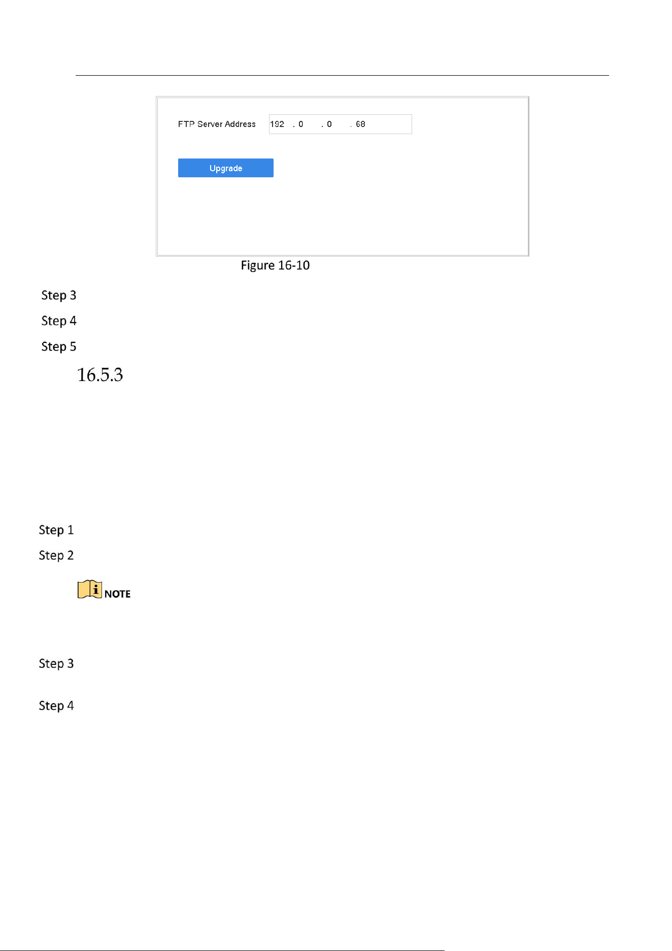
Network Video Recorder User Manual
161
FTP Upgrade Interface
Enter the FTP Server Address in the text field.
Click the Upgrade button to start upgrading.
After the upgrading is complete, reboot the device to activate the new firmware.
Upgrade by Hik-Connect
After logging the device in to Hik-Connect, the device would periodically check for the latest
firmware from Hik-Connect. If an upgrade firmware is available, the device will notify you when
you log in. You can also manually check for the latest firmware.
Before You Start
Ensure the device has successfully connected to Hik-Connect, and it requires to install at least
one read-write HDD for firmware downloading.
Go to Maintenance > Upgrade > Online Upgrade.
Click Check Upgrade to manually check for the latest firmware from Hik-Connect.
The device will automatically check for the latest firmware every 24 hours. If it detects available
upgrade firmware, the device will notify you when you log in.
(Optional) You can switch on Download Latest Package Automatically to automatically
download the latest firmware package.
Click Upgrade Now.
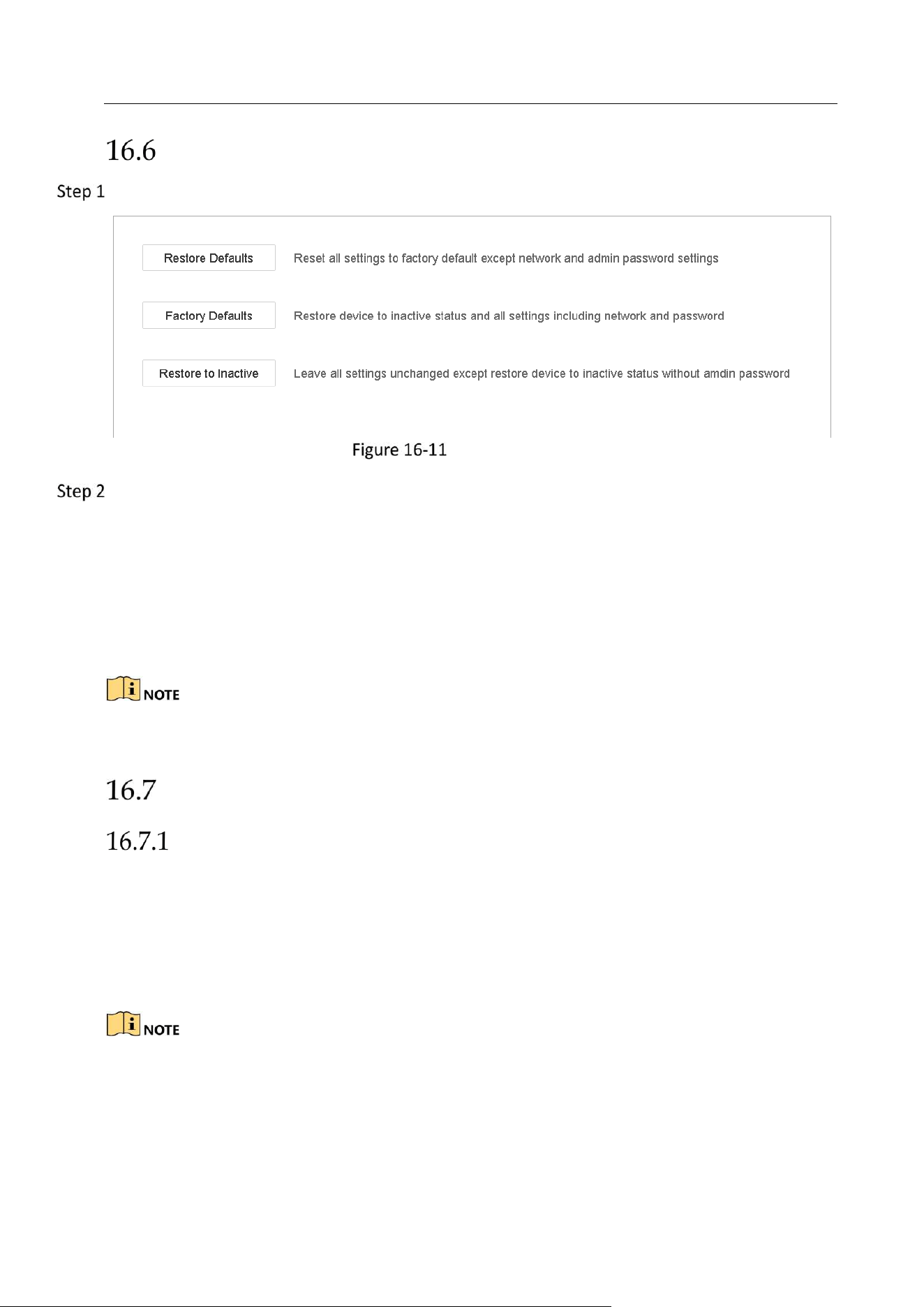
Network Video Recorder User Manual
162
Restore Default Settings
Go to Maintenance > Default.
Restore Defaults
Select the restoring type from the following three options.
Restore Defaults: Restore all parameters, except the network (including IP address, subnet
mask, gateway, MTU, NIC working mode, default route, server port, etc.) and user account
parameters, to the factory default settings.
Factory Defaults: Restore all parameters to the factory default settings.
Restore to Inactive: Restore the device to the inactive status.
The device will reboot automatically after restoring to the default settings.
System Service
Network Security Settings
HTTP
You can choose to disable the HTTP, or set the HTTP authentication when it is enabled as
demand to enhance the access security.
By default, the HTTP service is enabled.
Setting HTTP Authentication
Purpose
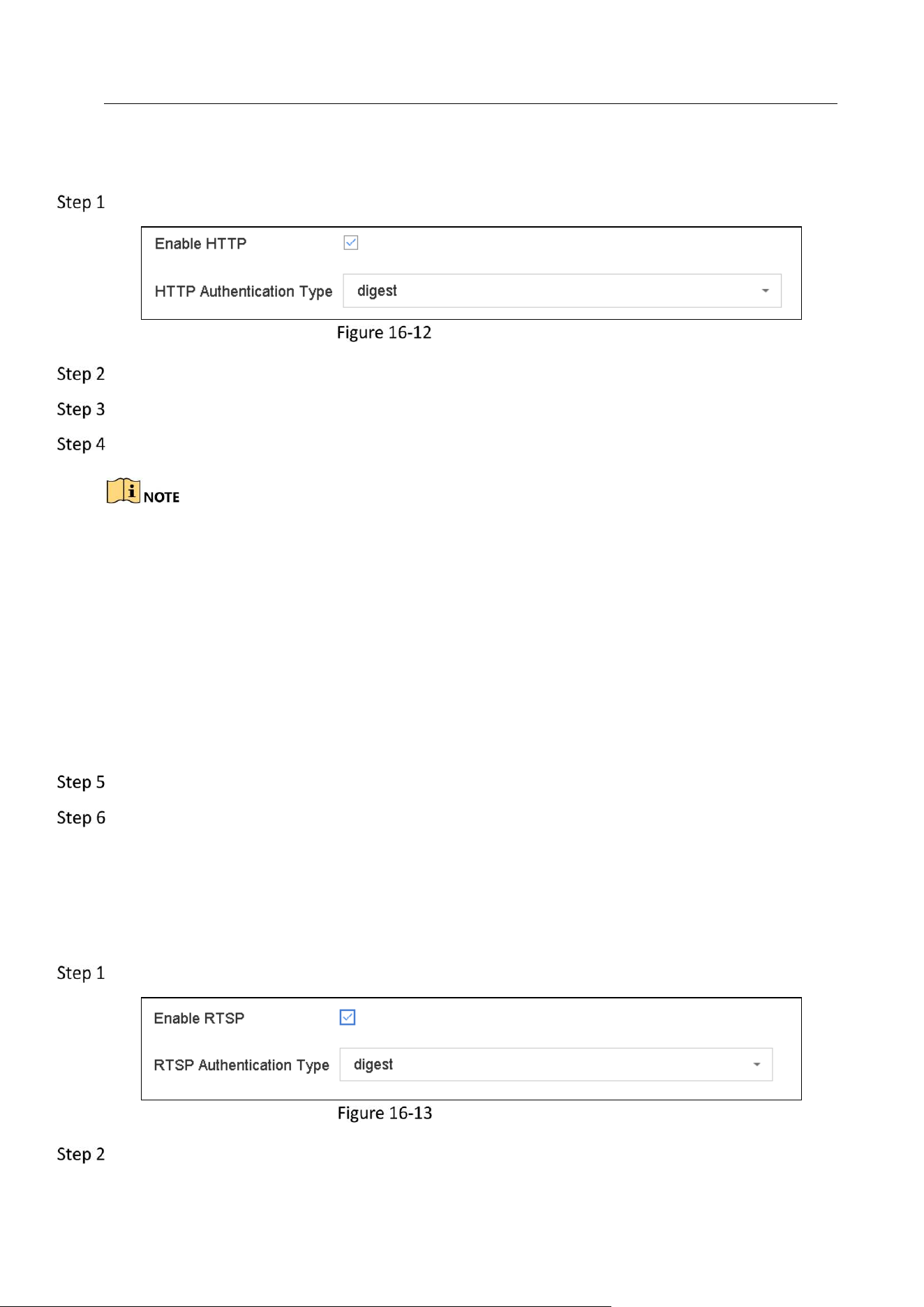
Network Video Recorder User Manual
163
If you need to enable the HTTP service, you can set the HTTP authentication to enhance the
access security.
Go to System > System Service > System Service.
HTTP Authentication
Check the Enable HTTP to enable the HTTP service.
Select the digest as the HTTP Authentication in the drop-down list.
Click Save to save the settings.
Two authentication types are selectable: digest and digest/basic. For security reasons, it is
recommended to select digest as the authentication type.
Disabling HTTP
Purpose
The admin user account can disable the HTTP service from the GUI or the web browser.
After the HTTP is disabled, all its related services, including the ISAPI, Onvif and Gennetc, will
terminate as well.
Go to System > System Service> System Service.
Uncheck the Enable HTTP to disable the HTTP service.
RTSP Authentication
Purpose
You can specifically secure the stream data of live view by setting the RTSP authentication.
Go to System > System Service> System Service.
RTSP Authentication
Select the authentication type.

Network Video Recorder User Manual
164
Two authentication types are selectable: digest and digest/basic. If you select digest, as the RTSP
authentication, only the request with digest authentication can access the video stream by the
RTSP protocol via the IP address. For security reasons, it is recommended to select digest as the
authentication type.
Click Save to save the settings.
Enable SDK Service
Purpose
SDK service is used for developing applications of hardware platform, software framework,
operating system, etc.
Go to System > System Service > System Service.
Check Enable SDK Service.
Click Apply to save the settings.
Restart the device to take effect the settings.
Enable Enhanced SDK Service
Purpose
The enhanced SDK service adopts TLS protocol over the SDK service that provides safer data
transmission.
Go to System > System Service > System Service.
Check Enable SDK Service.
Click Apply to save the settings.
Restart the device to take effect the settings.
The enhanced SDK service will restrict TLS outgoing bandwidth to max. 128 Mbps, when RAID is
enabled, the TLS outgoing bandwidth will be restricted to max. 64 Mbps.
Managing ONVIF User Accounts
Purpose
For the third-party camera connection to the device via ONVIF, you can enable ONVIF function
and manage the user accounts.
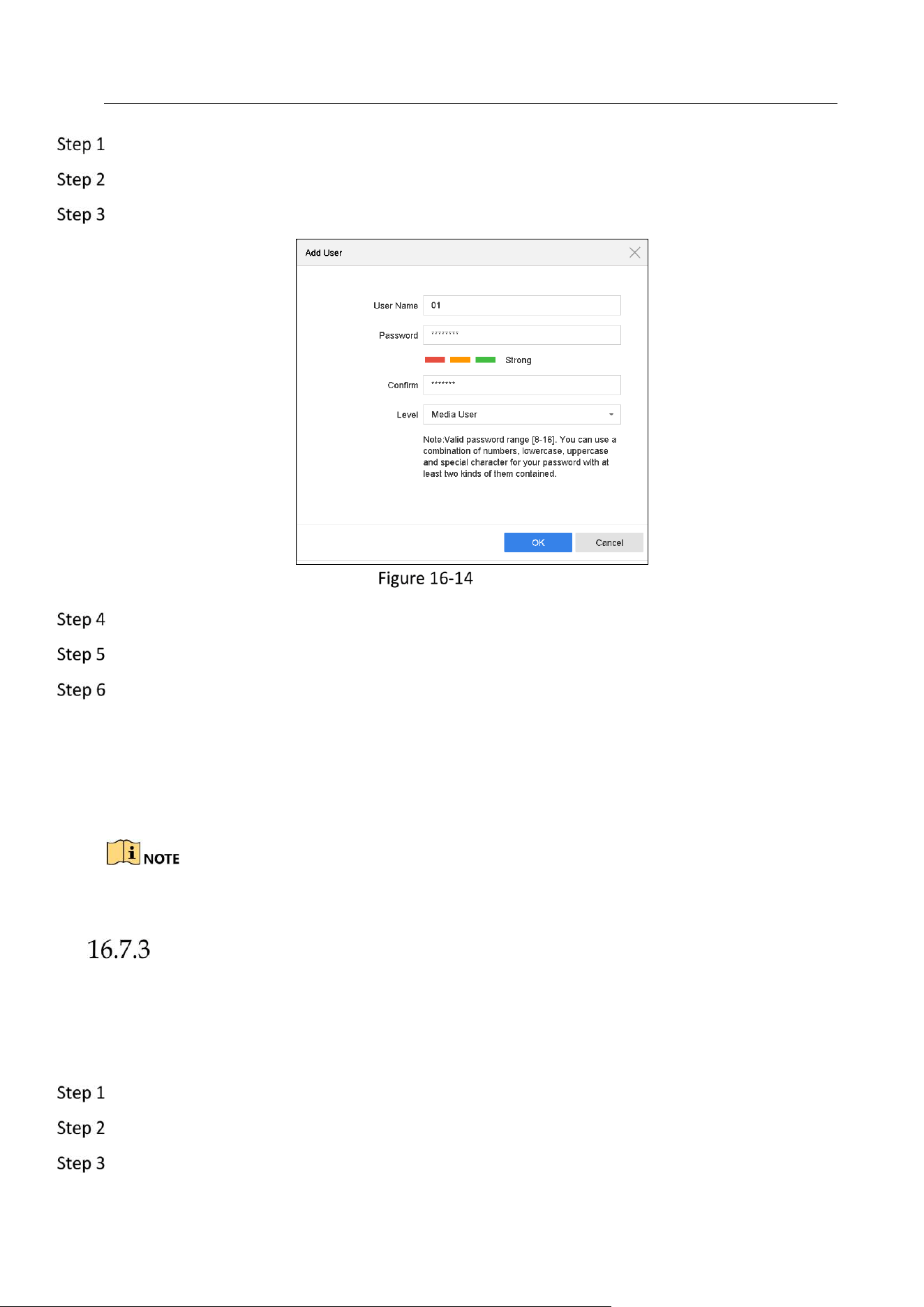
Network Video Recorder User Manual
165
Go to System > System Service > ONVIF.
Check Enable ONVIF to enable the ONVIF access management.
Click Add to enter the Add User interface.
Add User
Edit the user name, and enter the strong password.
Select the user level to Media User, Operator and Admin.
Click OK to save the settings.
Result:
The added user accounts have the permission to connect other devices to the device via ONVIF
protocol.
ONVIF protocol is disabled by default.
Managing IP Camera Activation
When you activate the device for the first-time access, you can set the activation password for the
IP camera(s) as well. Refer to Chapter 2.2 Activate the Device. And you can also manage the
password to enhance the security.
Go to System > System Service > IP Camera Activation.
Check the Change Password to enable the permission.
Enter the admin password of the device to obtain the permission.
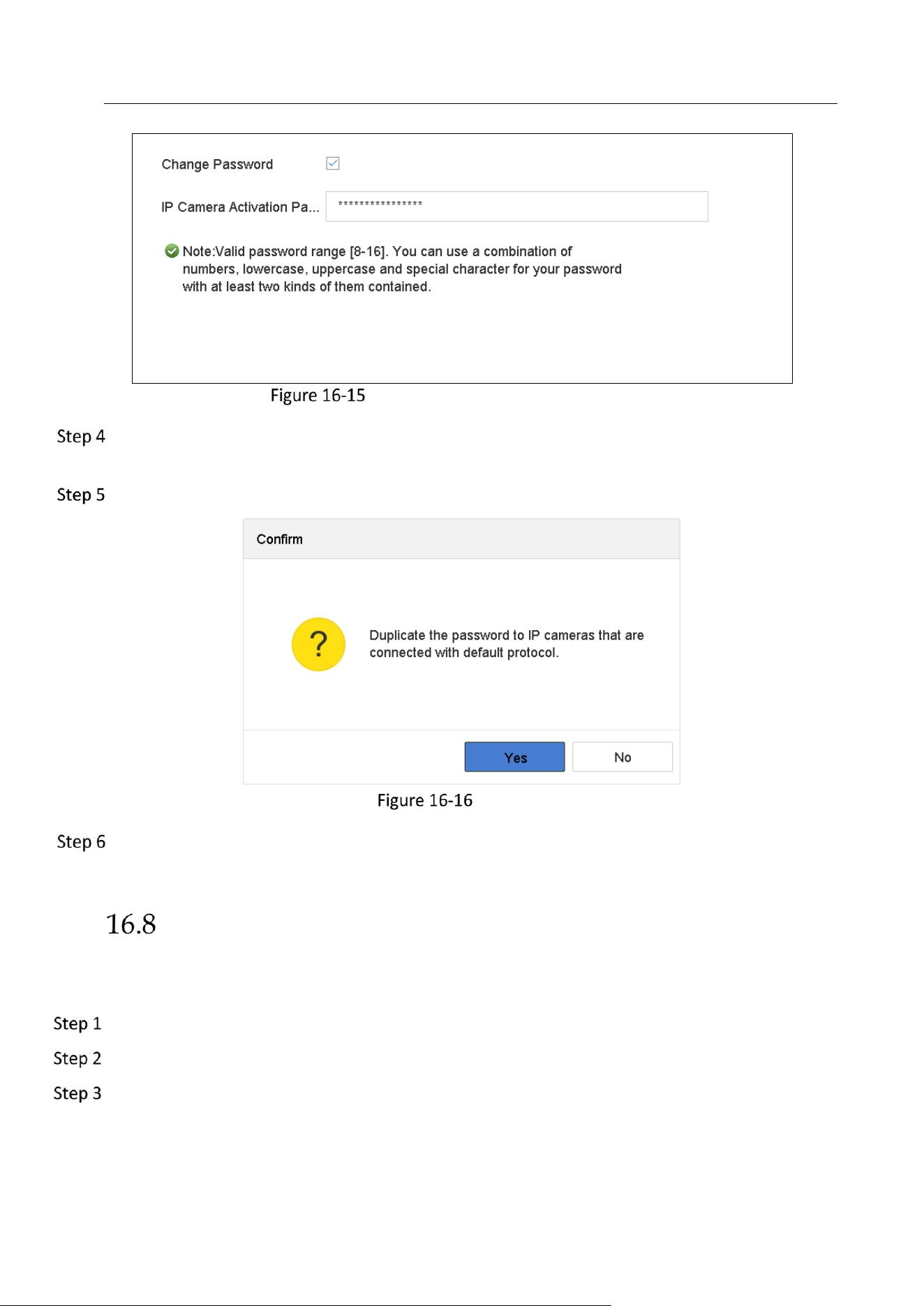
Network Video Recorder User Manual
166
Change IP Camera Activation Password
In the text filed of the IP Camera Activation Password, enter the new strong password for the
cameras.
Click Apply to have the following pop-up attention box.
Attention
Click Yes to duplicate the current password to the IP cameras which are connected with the
default protocol.
Configure Stream Encryption
The stream encryption enables to encrypt the streams for live view, playback, download,
backup, etc.
Go to Menu > Maintenance > System Service > Stream Encryption.
Check Enable Stream Encryption.
Create the encryption password.

Network Video Recorder User Manual
167
The stream encryption password is synchronized with the Hik-Connect service verification code.
After enabling the encryption code, the Hik-Connect stream will be forcedly encrypted. Make
sure the Hik-Connect service supports the stream encryption as well.
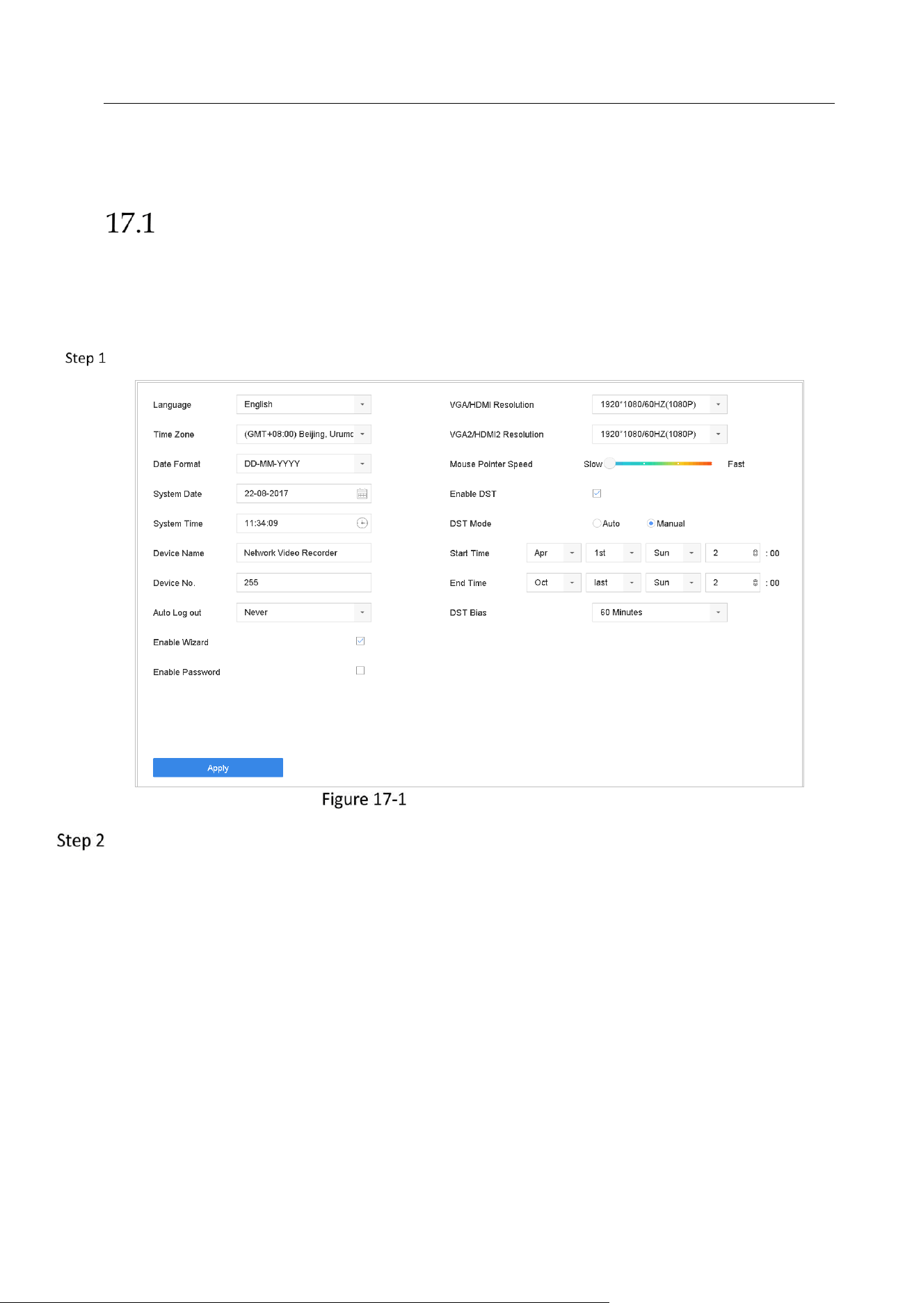
Network Video Recorder User Manual
168
Chapter 17 General System Settings
Configure General Settings
Purpose:
You can configure the BNC output standard, VGA output resolution, mouse pointer speed
through the System > General interface.
Go to System > General.
General Settings Interface
Configure the following settings.
Language: The default language used is English.
Output Standard: Select the output standard to NTSC or PAL, which must be the same with
the video input standard.
Resolution: Configure the resolution of the video output.
Device Name: Edit the name of the device
Device No.: Edit the serial number of the device. The Device No. can be set in the range of
1~255, and the default No. is 255. The number is used for the remote and keyboard control.
Auto Logout: Set timeout time for menu inactivity. E.g., when the timeout time is set to 5
Minutes, then the system will exit from the current operation menu to live view screen after
5 minutes of menu inactivity.
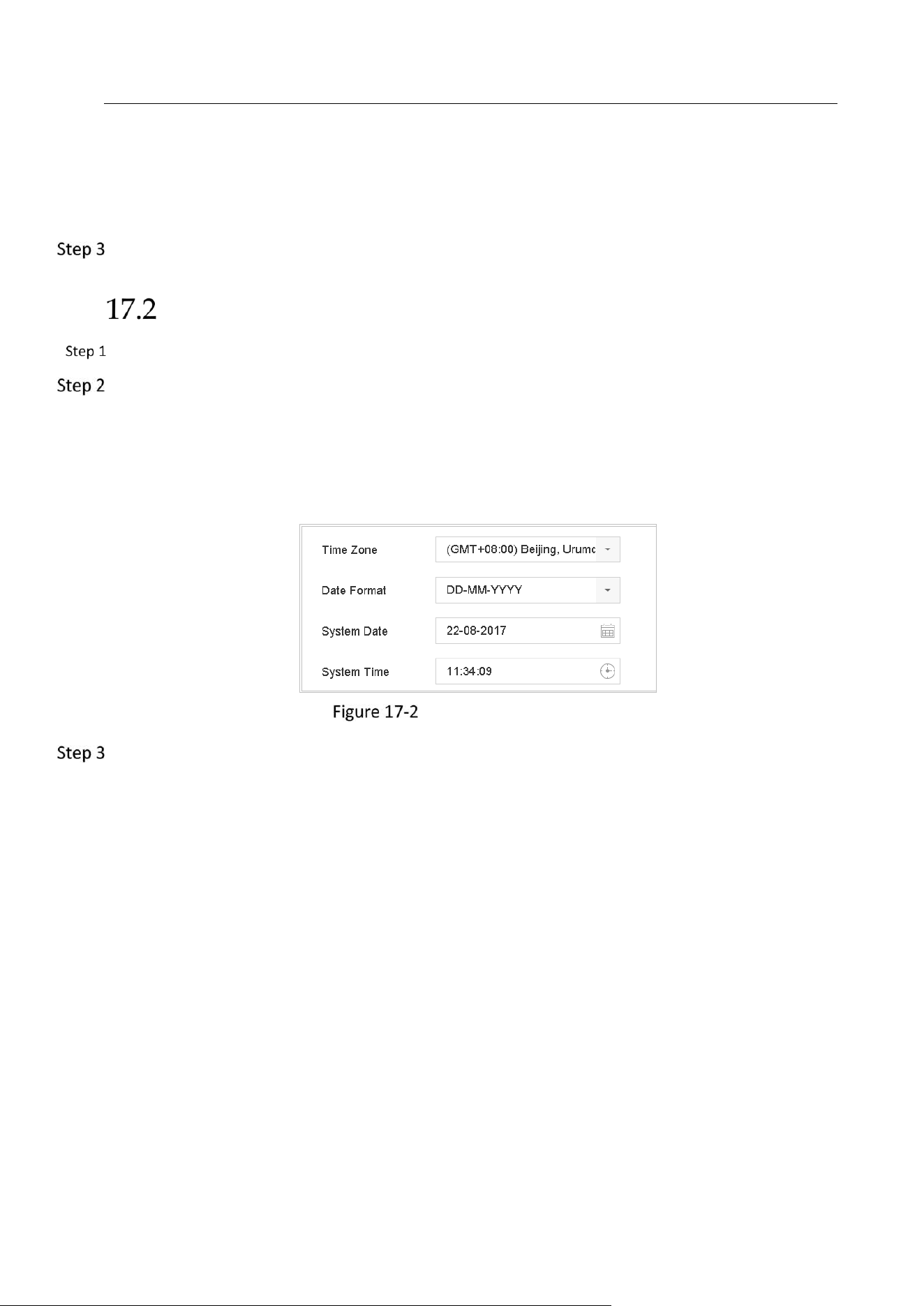
Network Video Recorder User Manual
169
Mouse Pointer Speed: Set the speed of mouse pointer; 4 levels are configurable.
Enable Wizard: Enable/disable the Wizard when the device starts up.
Enable Password: Enable/disable the use of the login password.
Click the Apply button to save the settings.
Configure Date & Time
Go to System > General.
Configure the date and time.
Time Zone: Select the time zone.
Date Format: Select the date format.
System Date: Select the system date.
System Time: Set the system time.
Date and Time Settings
Click the Apply button to save the settings.
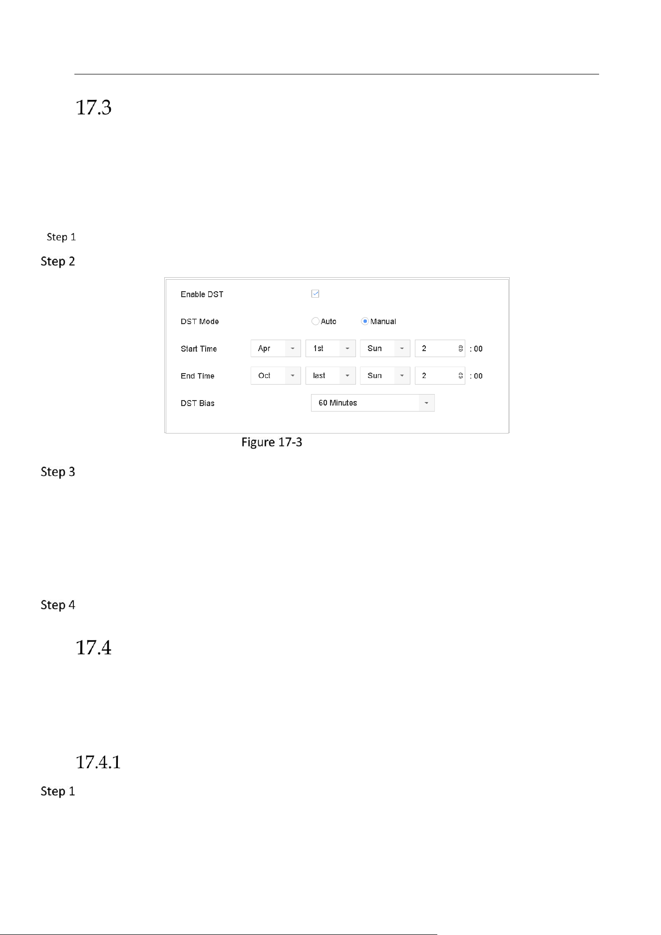
Network Video Recorder User Manual
170
Configure DST Settings
The DST (daylight saving time) refers to the period of the year when clocks are moved one
period ahead. In some areas worldwide, this has the effect of creating more sunlit hours in the
evening during months when the weather is the warmest.
We advance our clocks ahead a certain period (depends on the DST bias you set) at the
beginning of DST, and move them back the same period when we return to standard time (ST).
Go to System > General.
Check the Enable DST.
DST Settings Interface
Select the DST mode to Auto or Manual.
Auto: automatically enable the default DST period according to the local DST rules.
Manual: manually set the start time and end time of the DST period, and the DST bias.
DST Bias: set the time (30/60/90/120 minutes) offset from the standard time.
Example: The DST begins at 2:00 a.m. on the second Sunday of March and ends at 2:00 a.m. on
the first Sunday of November, with 60 minutes ahead.
Click the Apply button to save the settings.
Manage User Accounts
Purpose:
The Administrator user name is admin and the password is set when you start the device for the
first time. The Administrator has the permission to add and delete user and configure user
parameters.
Add a User
Go to System > User.
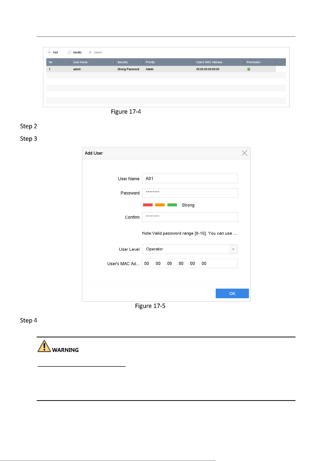
Network Video Recorder User Manual
171
User Management Interface
Click Add to enter the operation permission interface.
Enter the admin password and click OK.
Add User
In the Add User interface, enter the information for new user, including User Name, Password,
Confirm (password), User Level (Operator/Guest) and User’s MAC Address.
Strong Password recommended–We highly recommend you create a strong password of your
own choosing (Using a minimum of 8 characters, including at least three of the following
categories: upper case letters, lower case letters, numbers, and special characters.) in order to
increase the security of your product. And we recommend you reset your password regularly,
especially in the high security system, resetting the password monthly or weekly can better
protect your product.
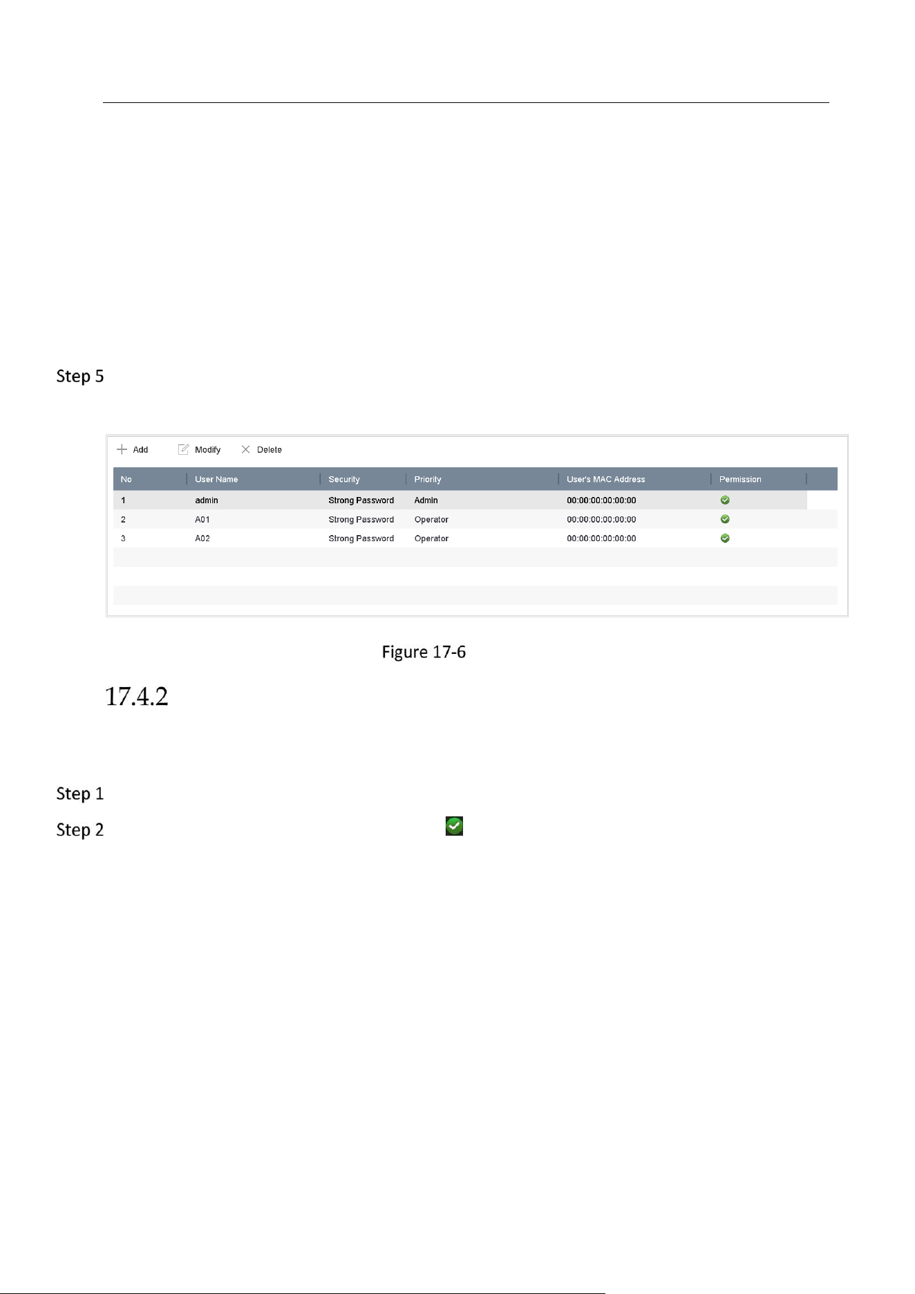
Network Video Recorder User Manual
172
User Level: Set the user level to Operator or Guest. Different user levels have different
operating permission.
Operator: The Operator user level has permission of Two-way Audio in Remote
Configuration and all operating permission in Camera Configuration by default.
Guest: The Guest user has no permission of Two-way Audio in Remote Configuration and
only has the local/remote playback in the Camera Configuration by default.
User’s MAC Address: The MAC address of the remote PC which logs onto the device. If it is
configured and enabled, it only allows the remote user with this MAC address to access the
device.
Click OK to finish the new user account adding.
Result: In the User Management interface, the added new user is displayed on the list.
User List
Set the Permission for a User
For the added user, you can assign the different permissions, including the local and remote
operation for the device.
Go to System > User.
Select a user from the list and then click the button to enter the permission settings
interface.
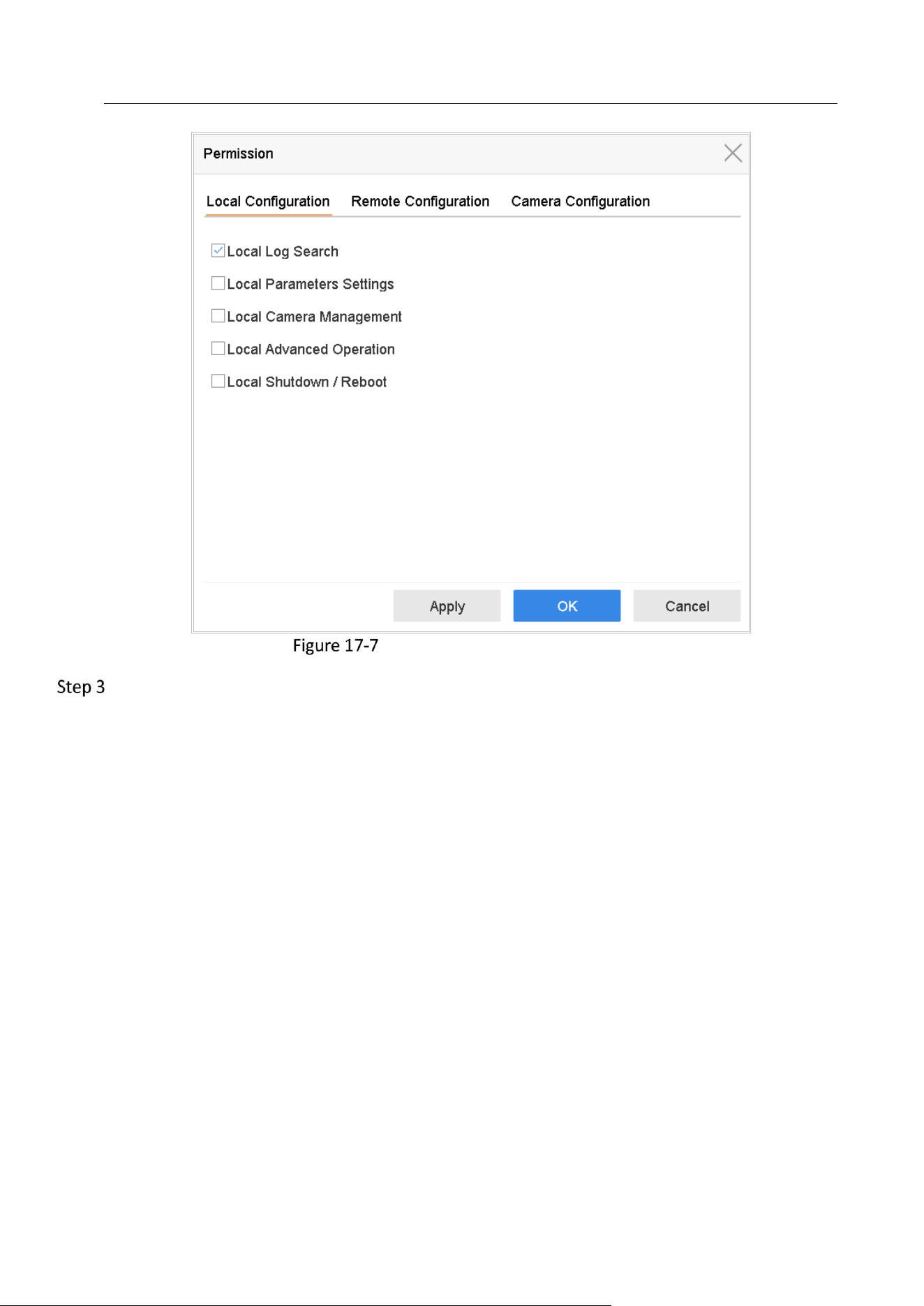
Network Video Recorder User Manual
173
User Permission Settings Interface
Set the operating permission of Local Configuration, Remote Configuration and Camera
Configuration for the user.
Local Configuration
Local Log Search: Searching and viewing logs and system information of device.
Local Parameters Settings: Configuring parameters, restoring factory default parameters and
importing/exporting configuration files.
Local Camera Management: The adding, deleting and editing of IP cameras.
Local Advanced Operation: Operating HDD management (initializing HDD, setting HDD
property), upgrading system firmware, clearing I/O alarm output.
Local Shutdown Reboot: Shutting down or rebooting the device.
Remote Configuration
Remote Log Search: Remotely viewing logs that are saved on the device.
Remote Parameters Settings: Remotely configuring parameters, restoring factory default
parameters and importing/exporting configuration files.
Remote Camera Management: Remote adding, deleting and editing of the IP cameras.
Remote Serial Port Control: Configuring settings for RS-232 and RS-485 ports.
Remote Video Output Control: Sending remote button control signal.
Two-Way Audio: Realizing two-way radio between the remote client and the device.
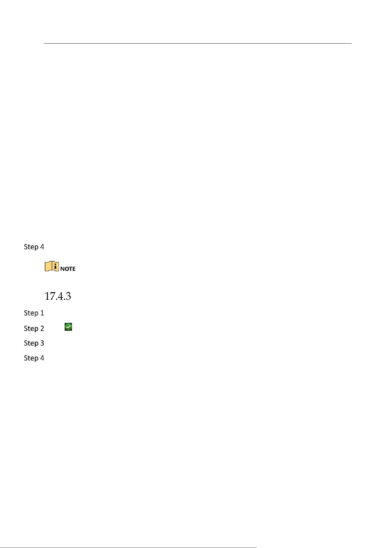
Network Video Recorder User Manual
174
Remote Alarm Control: Remotely arming (notify alarm and exception message to the remote
client) and controlling the alarm output.
Remote Advanced Operation: Remotely operating HDD management (initializing HDD, setting
HDD property), upgrading system firmware, clearing I/O alarm output.
Remote Shutdown/Reboot: Remotely shutting down or rebooting the device.
Camera Configuration
Remote Live View: Remotely viewing live video of the selected camera (s).
Local Manual Operation: Locally starting/stopping manual recording and alarm output of the
selected camera (s).
Remote Manual Operation: Remotely starting/stopping manual recording and alarm output of
the selected camera (s).
Local Playback: Locally playing back recorded files of the selected camera (s).
Remote Playback: Remotely playing back recorded files of the selected camera (s).
Local PTZ Control: Locally controlling PTZ movement of the selected camera (s).
Remote PTZ Control: Remotely controlling PTZ movement of the selected camera (s).
Local Video Export: Locally exporting recorded files of the selected camera (s).
Click OK to save the settings.
Only the admin user account has the permission of restoring factory default parameters.
Set Local Live View Permission for Non-Admin Users
Go to System > User.
Click of admin user.
Enter admin password and click OK.
Select cameras that non-admin user can view in local and click OK.
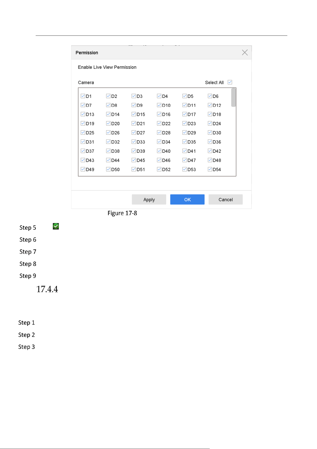
Network Video Recorder User Manual
175
Enable Live View Permission
Click of non-admin user.
Enter Camera Configuration tab.
Select Camera Permission as Local Live View.
Select cameras to live view.
Click OK.
Set Live View Permission on Lock Screen
The admin user can set live view permission for specific cameras in the screen lock status of
device.
Go to System > User.
Click Live View Permission on Lock Screen.
Input admin password and click Next.
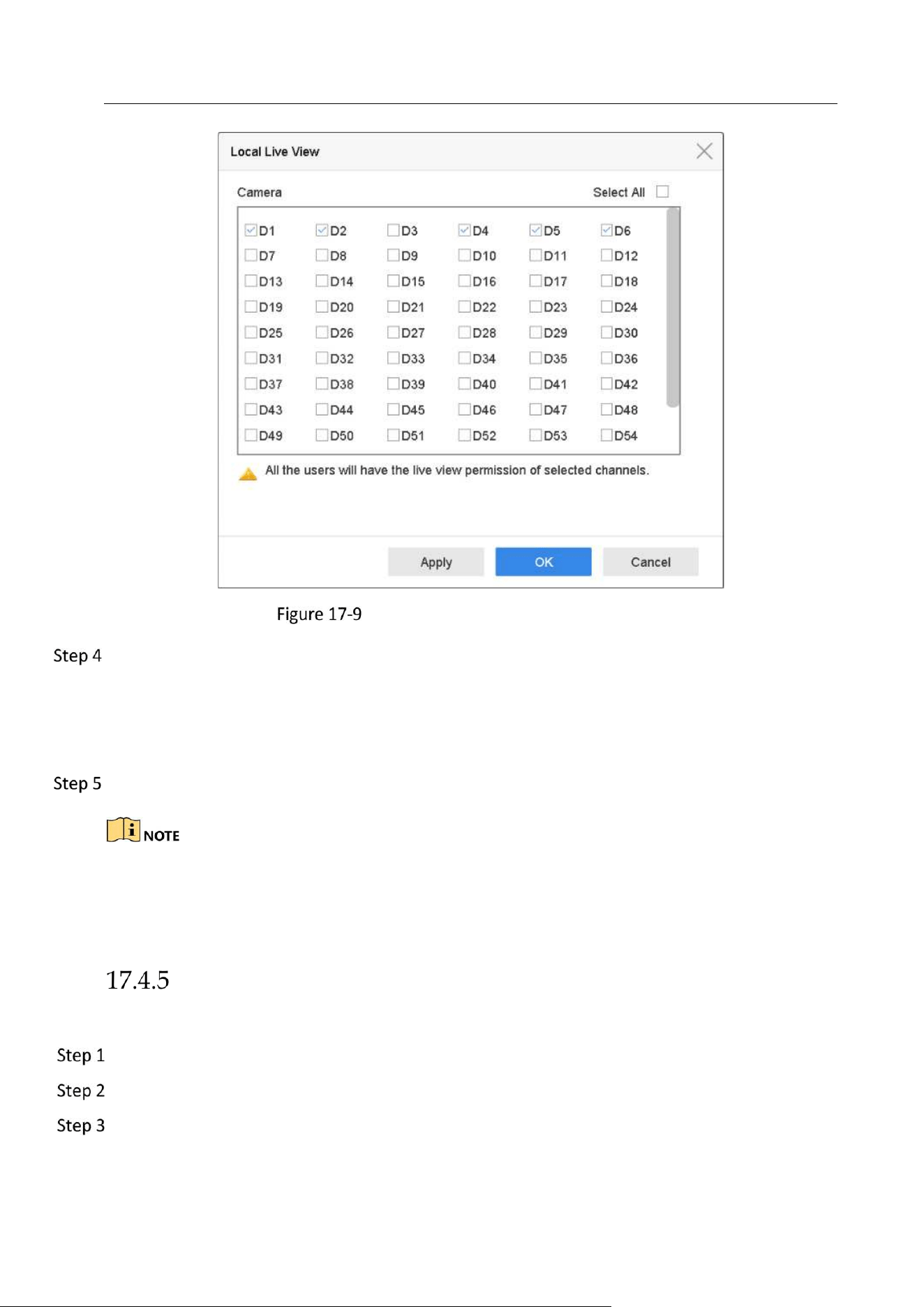
Network Video Recorder User Manual
176
Set Live View Permissions on Lock Screen
Set the permissions.
Select the camera (s) to allow live view when the current user account is in logout status.
Deselect the camera (s) to forbidden the camera (s) being viewed when the current user
account is in logout status.
Click OK.
The admin user can set this permission for user accounts.
When the normal user (Operator or Guest) has no local live view permission for specific
camera (s), the live view permission for such camera (s) on lock screen status cannot be
configured (live view not allowed by default).
Edit the Admin User
For the admin user account, you can modify your password and unlock pattern.
Go to System > User.
Select the admin user from the list.
Click Modify.
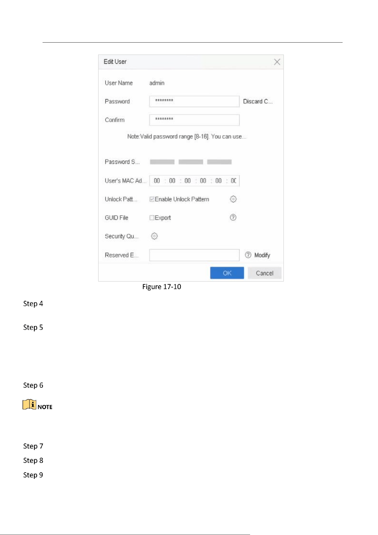
Network Video Recorder User Manual
177
Edit User (Admin)
Edit the admin user information as desired, including a new admin password (strong password
is required) and MAC address.
Edit the unlock pattern for the admin user account.
1) Check Enable Unlock Pattern to enable the use of an unlock pattern when logging in to
the device.
2) Use the mouse to draw a pattern among the 9 dots on the screen, and release the
mouse when the pattern is done.
Check Export of Export GUID to export the GUID file for the admin user account.
When the admin password is changed, export the new GUID to the connected USB flash disk in
the Import/Export interface for the future password resetting.
Configure security question for password resetting.
Configure reserved email for password resetting.
Click OK to save the settings.
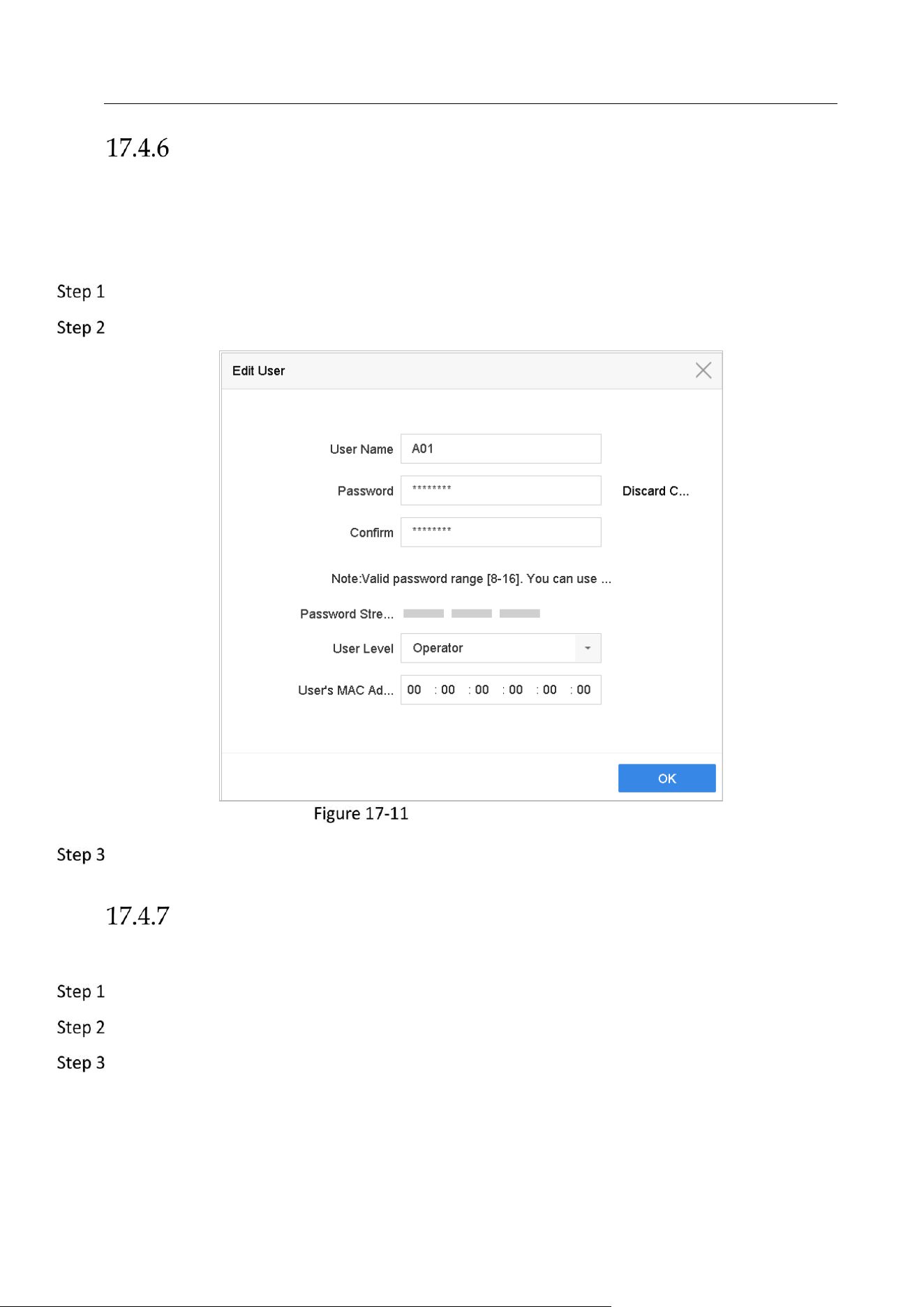
Network Video Recorder User Manual
178
Edit the Operator/Guest User
You can edit the user information, including user name, password, permission level and MAC
address. Check the checkbox of Change Password if you want to change the password, and
input the new password in the text field of Password and Confirm. A strong password is
recommended.
Go to System > User.
Select a user from the list and click Modify.
Edit User (Operator/Guest)
Edit the user information as demand, including the new password (strong password is
required), and MAC address.
Delete a User
The admin user account has the permission to delete the operator/guest user account.
Go to System > User.
Select a user from the list.
Click Delete to delete the selected user account.
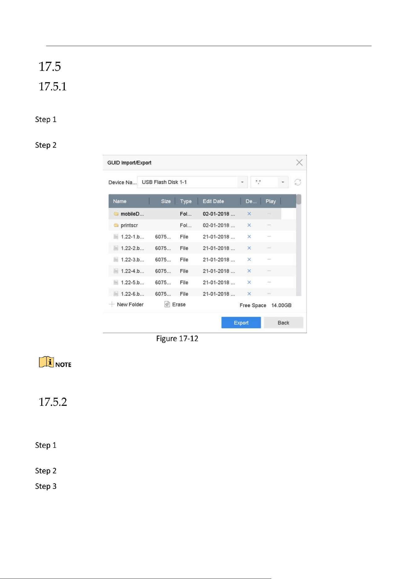
Network Video Recorder User Manual
179
Configure Password Security
Export GUID File
The GUID file may help you to reset password when you forget password.
Select to export GUID file when you are activating the device, or editing the admin user
account.
Insert the USB flash drive to your device, and export the GUID file to the USB flash drive.
Export GUID File
Please keep your GUID file properly for future password resetting.
Configure Security Questions
The security question configuration may help you to reset password when you forget your
password or encounter security issues.
Click Security Question Configuration when you are activating the device, or editing the
admin user account.
Select three security questions from the drop-down list and input the answers.
Click OK.
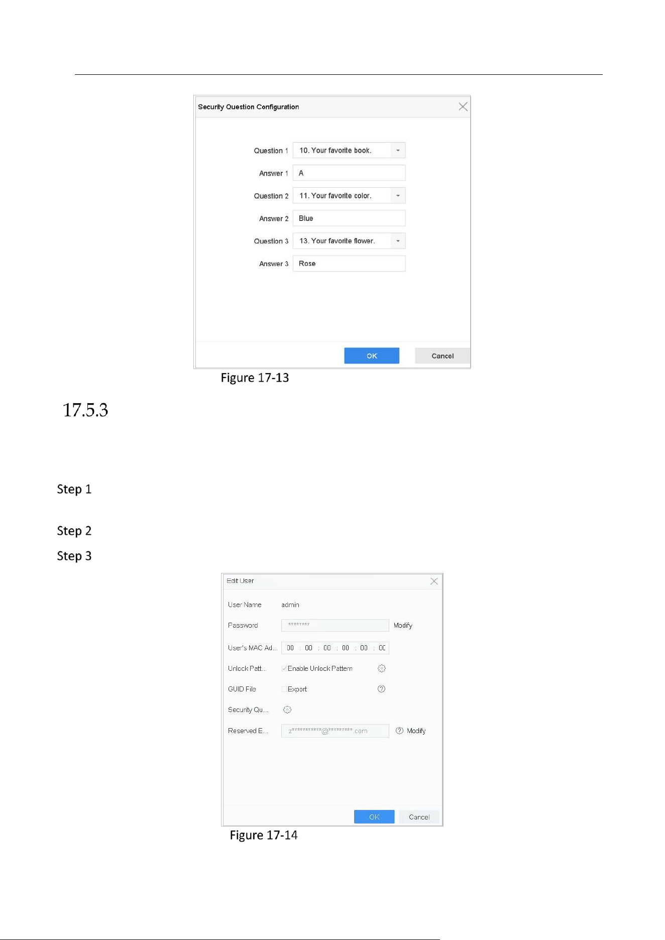
Network Video Recorder User Manual
180
Configure Security Questions
Configure Reserved Email
Purpose:
The reserved email will help you to reset password when you forget your password.
Check Reserved E-mail when you are activating the device, or click Modify when you are
editing the admin user account.
Enter reserved email address.
Click OK.
Configure Reserved Email
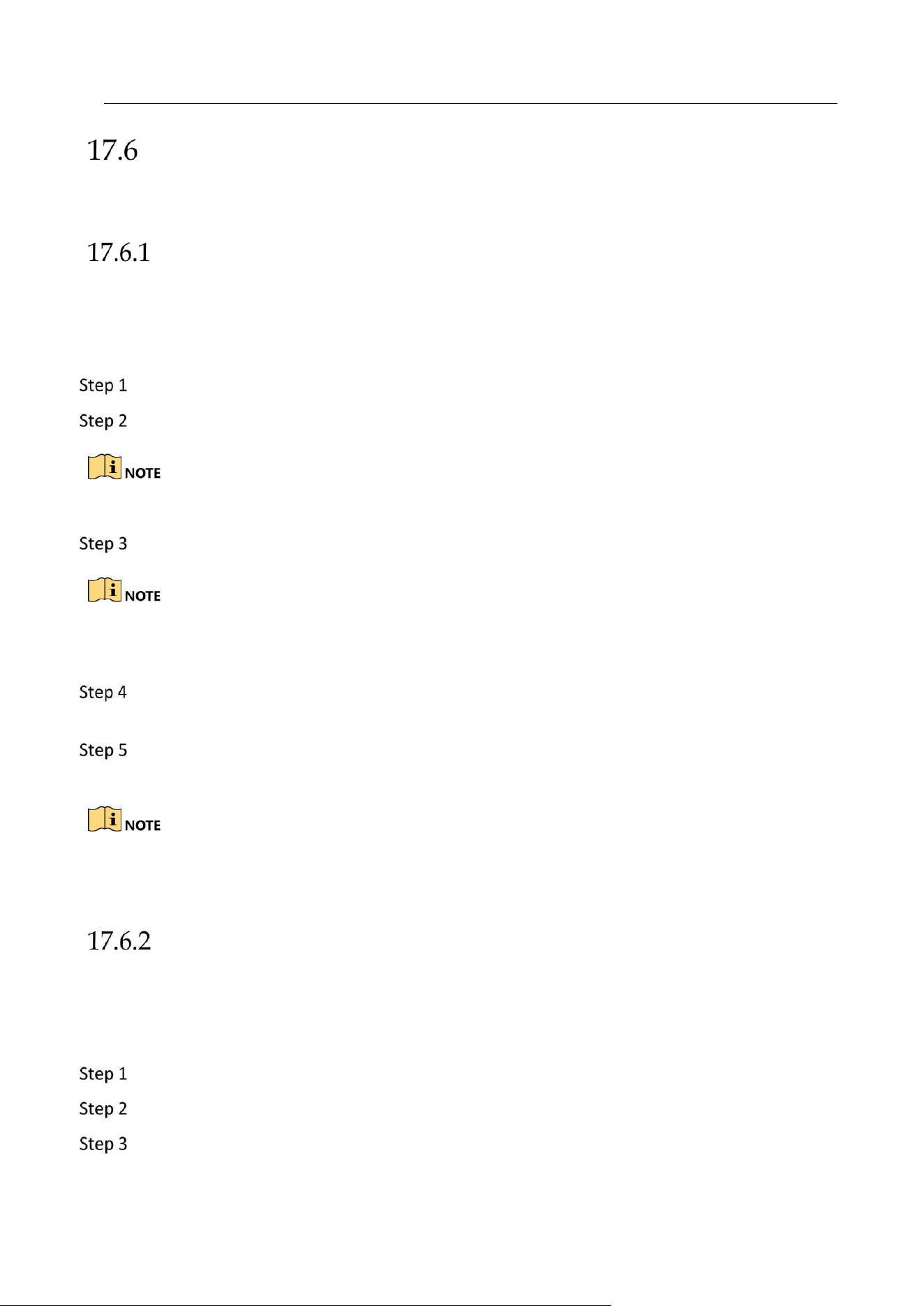
Network Video Recorder User Manual
181
Reset Password
When you forget the admin password, you can reset the password by importing the GUID file,
answering security questions, or entering verification code from your reserved email.
Reset Password by GUID
Before You Start
The GUID file must be exported and saved in the local U flash disk after you have activated the
device or edited the admin user account. (Refer to Chapter 17.5.1 Export GUID File).
On the user login interface, click Forgot Password.
Select the password resetting type to Verify by GUID.
Please insert the U flash disk stored with the GUID file to the NVR before resetting password.
Select the GUID file from the U flash disk and click Import to import the file to the device.
If you have imported the wrong GUIE file for 7 times, you will be not allowed to reset the
password for 30 minutes.
After the GUID file is successfully imported, enter the reset password interface to set the
new admin password.
Click OK to set the new password. You can export the new GUID file to the U flash disk for
future password resetting.
When the new password is set, the original GUID file will be invalid. The new GUID file should be
exported for future password resetting. You can also enter the User>User Management to edit
the admin user and export the GUID file.
Reset Password by Security Questions
Before You Start
You have configured the security questions when you activate the device or edit the admin user
account. (Refer to Chapter 17.5.2 Configure Security Questions).
On the user login interface, click Forgot Password.
Select the password resetting type to Verify by Security Question.
Input the correct answers of the three security questions.

Network Video Recorder User Manual
182
Click OK.
If the answers mismatch, the verification is failed.
Create the new admin password on the Reset Password interface.
Reset Password by Reserved Email
Before You Start
Ensure you have configured the reserved email when you are activating the device or editing the
admin user account. (Refer to 17.5.3 Configure Reserved Email)
On the user login interface, click Forgot Password.
Select the password resetting type to Verify by Reserved Email.
Click OK.
Click Next if you accept the legal disclaimer. You can use a smartphone to scan the QR code
to read the legal disclaimer.
Obtain the verification code. There are two ways to get the verification code.
− Use Hik-Connect app to scan the QR code. You can find the scanning tool in More > Reset
Device Password.
− Send the QR code to email server.
1) Insert a USB flash drive to your device.
2) Click Export to export the QR code to USB flash drive.
3) Email the QR code to pw_recovery@hikvision.com as attachment.
Check your reserved email, and you will receive a verification code within 5 minutes.
Enter the verification code.
Click OK to set the new password.

Network Video Recorder User Manual
183
Chapter 18 Appendix
Glossary
• Dual Stream: Dual stream is a technology used to record high resolution video locally while
transmitting a lower resolution stream over the network. The two streams are generated by
the device, with the main stream having a maximum resolution of 4CIF and the sub-stream
having a maximum resolution of CIF.
• HDD: Acronym for Hard Disk Drive. A storage medium which stores digitally encoded data on
platters with magnetic surfaces.
• DHCP: Dynamic Host Configuration Protocol (DHCP) is a network application protocol used by
devices (DHCP clients) to obtain configuration information for operation in an Internet
Protocol network.
• HTTP: Acronym for Hypertext Transfer Protocol. A protocol to transfer hypertext request and
information between servers and browsers over a network
• DDNS: Dynamic DNS is a method, protocol, or network service that provides the capability
for a networked device, such as a router or computer system using the Internet Protocol
Suite, to notify a domain name server to change, in real time (ad-hoc) the active DNS
configuration of its configured hostnames, addresses or other information stored in DNS.
• PPPoE: Stands for "Point-to-Point Protocol over Ethernet." PPPoE is a network configuration
used for establishing a PPP connection over an Ethernet protocol.
• Hybrid device: A hybrid device is a combination of a DVR and device.
• NTP: Acronym for Network Time Protocol. A protocol designed to synchronize the clocks of
computers over a network.
• NTSC: Acronym for National Television System Committee. NTSC is an analog television
standard used in such countries as the United States and Japan. Each frame of an NTSC signal
contains 525 scan lines at 60Hz.
• Device: Acronym for Network Video Recorder. A device can be a PC-based or embedded
system used for centralized management and storage for IP cameras, IP Domes and other
devices.
• PAL: Acronym for Phase Alternating Line. PAL is also another video standard used in
broadcast televisions systems in large parts of the world. PAL signal contains 625 scan lines at
50Hz.
• PTZ: Acronym for Pan, Tilt, Zoom. PTZ cameras are motor driven systems that allow the
camera to pan left and right, tilt up and down and zoom in and out.
• USB: Acronym for Universal Serial Bus. USB is a plug-and-play serial bus standard to interface
devices to a host computer.
Network Video Recorder User Manual
184
Troubleshooting
No image displayed on the monitor after starting up normally.
Possible Reasons:
− No VGA or HDMI connections.
− Connection cable is damaged.
− Input mode of the monitor is incorrect.
Verify the device is connected with the monitor via HDMI or VGA cable.
If not, please connect the device with the monitor and reboot.
Verify the connection cable is good.
If there is still no image display on the monitor after rebooting, please check if the connection
cable is good, and change a cable to connect again.
Verify Input mode of the monitor is correct.
Please check the input mode of the monitor matches with the output mode of the device (e.g. if
the output mode of device is HDMI output, then the input mode of monitor must be the HDMI
input). And if not, please modify the input mode of monitor.
Check if the fault is solved by the step 1 to step 3.
If it is solved, finish the process.
If not, please contact the engineer from Hikvision to do the further process.
There is an audible warning sound “Di-Di-Di-DiDi” after a new bought device starts up.
Possible Reasons:
− No HDD is installed in the device.
− The installed HDD has not been initialized.
− The installed HDD is not compatible with the device or is broken-down.
Verify at least one HDD is installed in the device.
− If not, please install the compatible HDD.
Please refer to the Quick Start Guide for the HDD installation steps.
− If you don’t want to install a HDD, go to Menu>System> Event>Normal Event>Exception, and
uncheck the Audible Warning checkbox of “HDD Error”.
Verify the HDD is initialized.

Network Video Recorder User Manual
185
1) Go to Menu>Storage>Storage Device.
2) If the status of the HDD is “Uninitialized”, please check the checkbox of corresponding
HDD and click the “Init” button.
Verify the HDD is detected or is in good condition.
1) Select Menu>Storage>Storage Device.
2) If the HDD is not detected or the status is “Abnormal”, please replace the dedicated HDD
according to the requirement.
Check if the fault is solved by the step 1 to step 3.
If it is solved, finish the process.
If not, please contact the engineer from Hikvision to do the further process.
The status of the added IP camera displays as “Disconnected” when it is connected through
Private Protocol. Select “Menu>Camera>Camera>IP Camera” to get the camera status.
Possible Reasons:
− Network failure, and the device and IP camera lost connections.
− The configured parameters are incorrect when adding the IP camera.
− Insufficient bandwidth.
Verify the network is connected.
1) Connect the device and PC with the RS-232 cable.
2) Open the Super Terminal software, and execute the ping command. Input “ping IP” (e.g.
ping 172.6.22.131).
Simultaneously press Ctrl and C to exit the ping command.
If there exists return information and the time value is little, the network is normal.
Verify the configuration parameters are correct.
1) Go to Menu>Camera.
2) Verify the following parameters are the same with those of the connected IP devices,
including IP address, protocol, management port, user name and password.
Verify the whether the bandwidth is enough.
1) Go to Menu>Maintenance>Net Detect>Network Stat.
2) Check the usage of the access bandwidth, and see if the total bandwidth has reached its
limit.
Check if the fault is solved by the step 1 to step 3.
If it is solved, finish the process.

Network Video Recorder User Manual
186
If not, please contact the engineer from Hikvision to do the further process.
The IP camera frequently goes online and offline and the status of it displays as
“Disconnected”.
Possible Reasons:
− The IP camera and the device versions are not compatible.
− Unstable power supply of IP camera.
− Unstable network between IP camera and device.
− Limited flow by the switch connected with IP camera and device.
Verify the IP camera and the device versions are compatible.
1) Go to Menu>Camera, and view the firmware version of connected IP camera.
2) Go to Menu>Maintenance>System Info>Device Info and view the firmware version of
device.
Verify power supply of IP camera is stable.
1) Verify the power indicator is normal.
2) When the IP camera is offline, please try the ping command on PC to check if the PC
connects with the IP camera.
Verify the network between IP camera and device is stable.
1) When the IP camera is offline, connect PC and device with the RS-232 cable.
2) Open the Super Terminal, use the ping command and keep sending large data packages
to the connected IP camera, and check if there exists packet loss.
Simultaneously press Ctrl and C to exit the ping command.
Example: Input ping 172.6.22.131 –l 1472 –f.
Verify the switch is not flow control.
Check the brand, model of the switch connecting IP camera and device, and contact with the
manufacturer of the switch to check if it has the function of flow control. If so, please turn it
down.
Check if the fault is solved by the step 1 to step 4.
If it is solved, finish the process.
If not, please contact the engineer from Hikvision to do the further process.
No monitor connected with the device locally and when you manage the IP camera to
connect with the device by web browser remotely, of which the status displays as Connected.

Network Video Recorder User Manual
187
And then you connect the device with the monitor via VGA or HDMI interface and reboot the
device, there is black screen with the mouse cursor.
Connect the device with the monitor before startup via VGA or HDMI interface, and manage
the IP camera to connect with the device locally or remotely, the status of IP camera displays
as Connect. And then connect the device with the CVBS, and there is black screen either.
Possible Reasons:
After connecting the IP camera to the device, the image is output via the main spot interface by
default.
Enable the output channel.
Go to Menu>System>Live View>General, and select video output interface in the drop-down
list and configure the window you want to view.
The view settings can only be configured by the local operation of device.
Different camera orders and window-division modes can be set for different output
interfaces separately, and digits like “D1”and “D2” stands for the channel number, and “X”
means the selected window has no image output.
Check if the fault is solved by the above steps.
If it is solved, finish the process.
If not, please contact the engineer from Hikvision to do the further process.
Live view stuck when video output locally.
Possible Reasons:
− Poor network between device and IP camera, and there exists packet loss during the
transmission.
− The frame rate has not reached the real-time frame rate.
Verify the network between device and IP camera is connected.
When image is stuck, connect the RS-232 ports on PC and the rear panel of device with the RS-
232 cable.
Open the Super Terminal, and execute the command of “ping 192.168.0.0 –l 1472 –f” (the IP
address may change according to the real condition), and check if there exists packet loss.
Simultaneously press Ctrl and C to exit the ping command.
Verify the frame rate is real-time frame rate.

Network Video Recorder User Manual
188
Go to Menu>Camera>Encoding Parameters, and set the Frame rate to Full Frame.
Check if the fault is solved by the above steps.
If it is solved, finish the process.
If not, please contact the engineer from Hikvision to do the further process.
Live view stuck when video output remotely via the Internet Explorer or platform software.
Possible Reasons:
− Poor network between device and IP camera, and there exists packet loss during the
transmission.
− Poor network between device and PC, and there exists packet loss during the transmission.
− The performances of hardware are not good enough, including CPU, memory, etc..
Verify the network between device and IP camera is connected.
1) When image is stuck, connect the RS-232 ports on PC and the rear panel of device with
the RS-232 cable.
2) Open the Super Terminal, and execute the command of “ping 192.168.0.0 –l 1472 –f”
(the IP address may change according to the real condition), and check if there exists
packet loss.
Simultaneously press Ctrl and C to exit the ping command.
Verify the network between device and PC is connected.
1) Open the cmd window in the Start menu, or you can press “windows+R” shortcut key to
open it.
2) Use the ping command to send large packet to the device, execute the command of “ping
192.168.0.0 –l 1472 –f” (the IP address may change according to the real condition), and
check if there exists packet loss.
Simultaneously press Ctrl and C to exit the ping command.
Verify the hardware of the PC is good enough.
Simultaneously press Ctrl, Alt and Delete to enter the windows task management interface,
as shown in the following figure.
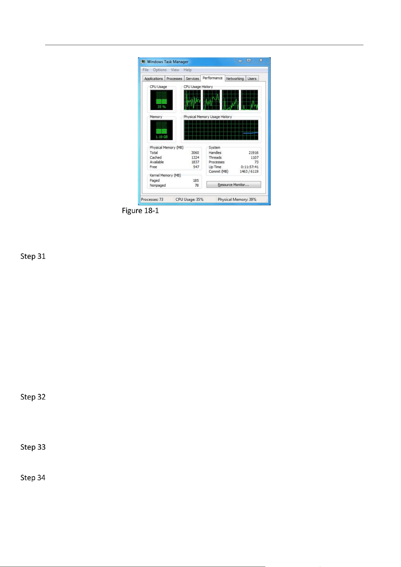
Network Video Recorder User Manual
189
Windows task management interface
Select the “Performance” tab; check the status of the CPU and Memory.
If the resource is not enough, please end some unnecessary processes.
Check if the fault is solved by the above steps.
If it is solved, finish the process.
If not, please contact the engineer from Hikvision to do the further process.
When using the device to get the live view audio, there is no sound or there is too much
noise, or the volume is too low.
Possible Reasons:
− Cable between the pickup and IP camera is not connected well; impedance mismatches or
incompatible.
− The stream type is not set as “Video & Audio”.
− The encoding standard is not supported with device.
Verify the cable between the pickup and IP camera is connected well; impedance matches and
compatible.
Log in the IP camera directly, and turn the audio on, check if the sound is normal. If not,
please contact the manufacturer of the IP camera.
Verify the setting parameters are correct.
Go to Menu>Camera>Encoding Parameters, and set the Stream Type as “Audio & Video”.
Verify the audio encoding standard of the IP camera is supported by the device.

Network Video Recorder User Manual
190
The device supports G722.1 and G711 standards, and if the encoding parameter of the input
audio is not one of the previous two standards, you can log in the IP camera to configure it to
the supported standard.
Check if the fault is solved by the above steps.
If it is solved, finish the process.
If not, please contact the engineer from Hikvision to do the further process.
The image gets stuck when device is playing back by single or multi-channel.
Possible Reasons:
− Poor network between device and IP camera, and there exists packet loss during the
transmission.
− The frame rate is not the real-time frame rate.
− The device supports up to 16-channel synchronize playback at the resolution of 4CIF, if you
want a 16-channel synchronize playback at the resolution of 720p, the frame extracting may
occur, which leads to a slight stuck.
Verify the network between device and IP camera is connected.
1) When image is stuck, connect the RS-232 ports on PC and the rear panel of device with the
RS-232 cable.
2) Open the Super Terminal, and execute the command of “ping 192.168.0.0 –l 1472 –f” (the IP
address may change according to the real condition), and check if there exists packet loss.
Simultaneously press the Ctrl and C to exit the ping command.
Verify the frame rate is real-time frame rate.
Select “Menu > Record > Parameters > Record”, and set the Frame Rate to “Full Frame”.
Verify the hardware can afford the playback.
Reduce the channel number of playback.
Go to Menu>Camera>Encoding Parameters, and set the resolution and bitrate to a lower
level.
Reduce the number of local playback channel.
Go to Menu>Playback, and uncheck the checkbox of unnecessary channels.
Check if the fault is solved by the above steps.
If it is solved, finish the process.
If not, please contact the engineer from Hikvision to do the further process.

Network Video Recorder User Manual
191
No record file found in the device local HDD, and prompt “No record file found”.
Possible Reasons:
− The time setting of system is incorrect.
− The search condition is incorrect.
− The HDD is error or not detected.
Verify the system time setting is correct.
Go to Menu>System>General, and verify the “Device Time” is correct.
Verify the search condition is correct.
Go to playback interface, and verify the channel and time are correct.
Verify the HDD status is normal.
Go to Menu>Storage>Storage Device to view the HDD status, and verify the HDD is detected
and can be read and written normally.
Check if the fault is solved by the above steps.
If it is solved, finish the process.
If not, please contact the engineer from Hikvision to do the further process.

Network Video Recorder User Manual
192
UD12787B