
Loading ...
Loading ...
Loading ...
21
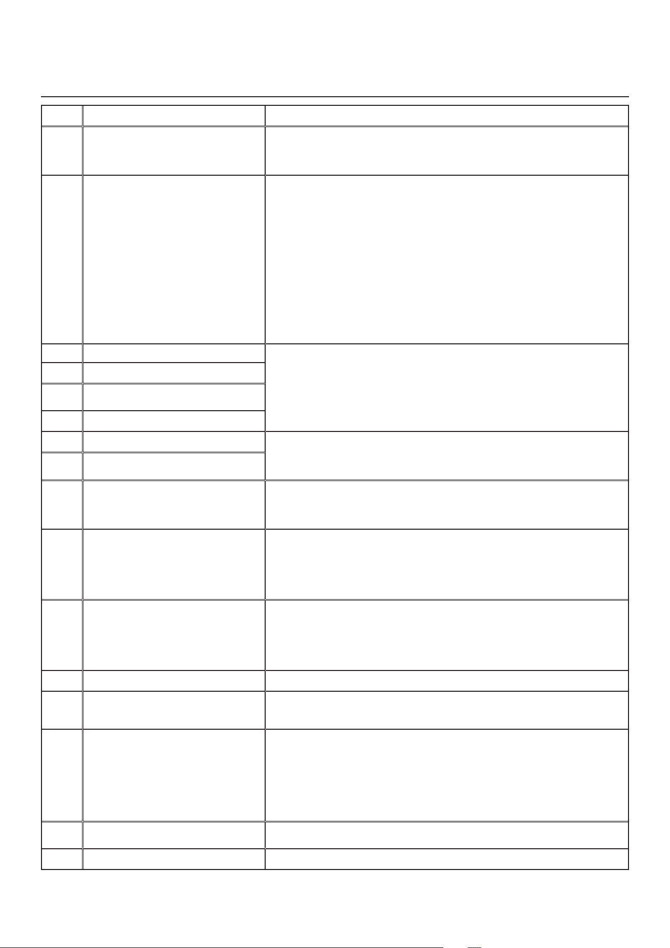
e
rror
d
eSCription
S
olution
E26
Supplymotor(driveovertemp)
STEP 1: Validate if the air exchanger is exposed to ambient temperatures
within the operating limits (see p. 4)
IfSTEP1didnot�xtheproblem,performSTEP2:Replacetheelectronic
assembly.
E32
Exhaustairow
STEP 1: Unplug the unit. Perform a visual inspection of the exhaust damper
system.Clean�lters,distributionregistersandoutsideexhausthood.Make
sure no non-return damper is installed in exhaust hood since it can freeze in
winter. Inspect ducting to ensure it is not squeezed or bent. Plug the unit.
IfSTEP1didnot�xtheproblem,performSTEP2:Removeductingofthe
supplypath.OntheLCDscreen,selectMAXtocheckiftheunitisableto
reachtheselectedow.Ifso,reviewtheductingpath.
IfSTEP2didnot�xtheproblem,performSTEP3:OntheLCDscreen,select
theMINandMAXowsettingvaluesthenresettheunit.MAXowvaluewill
displayontheLCDscreen.IfMAXowisabovedesiredMAXow,setMAX
andMINows.
IfSTEP3didnot�xtheproblem,performSTEP4:Replacetheexhaust
blower and repeat STEP 3.
IfSTEP4didnot�xtheproblem,performSTEP5:Replacetheelectronic
assembly. See also section 8.1.
E33
Exhaustmotor(driveovercurrent)
STEP 1: Unplug/plug unit.
IfSTEP1didnot�xtheproblem,performSTEP2:Removecoreandclearthe
ventilation wheel from any dirt or obstacles.
IfSTEP2didnot�xtheproblem,performSTEP3:DisconnectJ3(red)and
connect a spare blower system. If it works, replace exhaust blower.
IfSTEP3didnot�xtheproblem,performSTEP4:Replacetheelectronic
assembly.
E37
Exhaustmotor(drivefocduration)
E38
Exhaustmotor(drivespeed
feedback)
E39
Exhaustmotor(startup)
E34
Exhaustmotor(driveovervoltage)
STEP 1: Unplug/plug unit. Under and over voltage may be detected with
severein-housepowersupplyuctuationandstopthemotorforprotection.
IfSTEP1didnot�xtheproblem,performSTEP2:Replacetheelectronic
assembly.
E35
Exhaustmotor(driveundervoltage)
E36
Exhaustmotor(driveovertemp)
STEP 1: Validate if the air exchanger is exposed to ambiant temperatures
within the operating limits (see p. 4)
IfSTEP1didnot�xtheproblem,performSTEP2:Replacetheelectronic
assembly.
E40
Outside air thermistor STEP 1: Check if thermistor is well connected in connector J7A.
IfSTEP1didnot�xtheproblem,performSTEP2:DisconnectconnectorJ7A
and check if the measured resistance (thermistor connector) is within
5 Kohms to 120 Kohms. If outside the range, replace the thermistor.
IfSTEP2didnot�xtheproblem,performSTEP3:Replacetheelectronic
assembly.
E41
Distributionairthermistor
STEP 1: Check if thermistor is well connected in connector J7B.
IfSTEP1didnot�xtheproblem,performSTEP2:DisconnectconnectorJ7B
and check if the measured resistance (thermistor connector) is within
5 Kohms to 120 Kohms. If outside the range, replace the thermistor.
IfSTEP2didnot�xtheproblem,performSTEP3:Replacetheelectronic
assembly.
E42
PCBA thermistor fault
STEP 1: Replace the electronic assembly.
E43
PCBA temperature over limit
STEP 1: Validate if the air exchanger is exposed to ambiant temperatures
within the operating limits (see p. 4)
IfSTEP1didnot�xtheproblem,performSTEP2:Replacetheelectronicassembly.
E50
Wall control communication lost
STEP 1: Unplug unit, inspect wires, plug unit.
IfSTEP1didnot�xtheproblem,performSTEP2:Removewallcontrolfrom
the wall installation and test with a short cable. If it works, bring a new cable
to the wall installation location.
IfSTEP2didnot�xtheproblem,performSTEP3:Testtheairexchangerwith
a spare wall control. If it works, replace the wall control.
IfSTEP3didnot�xtheproblem,performSTEP4:Replacetheelectronic
assembly.
E51
Wall control sensor
STEP 1: Unplug unit, inspect wires, plug unit.
IfSTEP1didnot�xtheproblem,performSTEP2:Replacethewallcontrol.
E60
Protection mode
STEP1:Performgeneralinspectionoftheunit(dampers,core,�lters).
8.INSTALLER’STROUBLESHOOTING(
Cont
’
d
)
Loading ...
Loading ...
Loading ...