USER AND INSTALLER MANUAL
INSTALLER: READ THESE INSTRUCTIONS
SAVE THEM FOR USER
1107074
rev
. C
VB0360
REGISTER YOUR PRODUCT ONLINE AT:
www.venmar.ca/register-your-product.html or
www.vanee.ca/en/register-your-product.html
For additional information, visit venmar.ca or vanee.ca
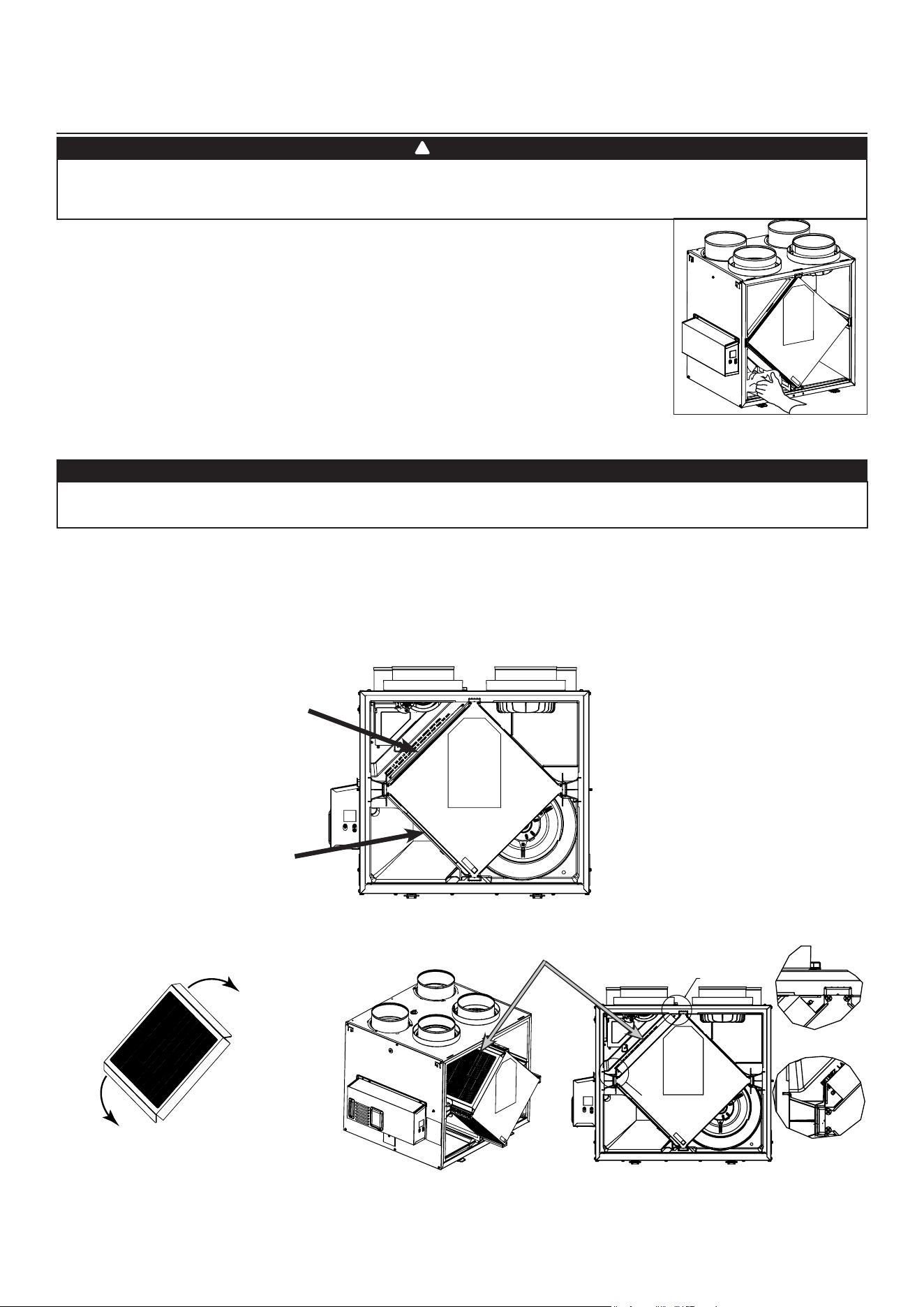
A180H75rT*
A180E75RT*
A230H75RT* A230H75RS*
A210E75RT* A210E75RS*
v180H75rT*
V180E75RT*
V230H75RT* V230H75RS*
V210E75RT* V210E75RS*
Venmar Ventilation ULC, 550 Lemire Blvd., Drummondville, Québec, Canada J2C 7W9 venmar.ca / vanee.ca 800-567-3855
*T
Hese
producTs
eArned
THe
enerGY
sTAr
®
bY
meeTinG
sTricT
enerGY
efficiencY
Guidelines
seT
bY
n
ATurAl
r
esources
c
AnAdA
And
THe
us epA. T
HeY
meeT
enerGY sTAr
requiremenTs
onlY
wHen
used
in
c
AnAdA
.

2
Please take note that this manual uses the following symbols to emphasize particular information:
Identi�esaninstructionwhich,ifnotfollowed,mightcauseseriouspersonalinjuriesincludingpossibilityof
death.
CAUTION
Denotes an instruction which, if not followed, may severely damage the unit and/or its components.
NOTE: Indicates supplementary information needed to fully complete an instruction.
LIMITATION
For an installation and use in Canada only. Intended for a building on which Part 9 of division B from the effective version
ot the National Building Code of Canada applies with additional restrictions and exception (see page 25 for more details).
Installationworkandelectricalwiringmust be donebyaquali�edpersoninaccordancewithallapplicablecodesand
standards,including�re-ratedconstructioncodesandstandards.
⚠
WARNING
TO REDUCE THE RISK OF FIRE, ELECTRIC SHOCK, OR INJURY TO PERSON(S) OBSERVE THE FOLLOWING:
1. Use this unit only in the manner intended by the manufacturer.
2. Before servicing or cleaning this unit, disconnect power cord from electrical outlet.
3. This unit is not designed to provide combustion and/or dilution air for fuel-burning appliances.
4. When cutting or drilling into a wall or ceiling, do not damage electrical wiring and other hidden utilities.
5. Donotusethisunitwithanysolid-statespeedcontroldeviceotherthanthosespeci�edinsection3.1.
6. This unit must be grounded. The power supply cord has a 3-prong grounding plug for your personal safety. It must be
plugged into a mating 3-prong grounding receptacle, grounded in accordance with the national electrical code and local
codes and ordinances. Do not remove the ground prong. Do not use an extension cord.
7. Do not install in a cooking area or connect directly to any appliances.
8. Do not use to exhaust hazardous or explosive materials and vapors.
9. When performing installation, servicing or cleaning this unit, it is recommended to wear safety glasses and gloves.
10. When applicable local regulation comprises more restrictive installation and/or certi�cation requirements, the
aforementioned requirements prevail on those of this document and the installer agrees to conform to these at his own
expenses.
CAUTION
1. Toavoidprematurelyclogged�lters,turntheunitOFFduringconstructionorrenovation.
2. Pleasereadspeci�cationlabelonproductforfurtherinformationandrequirements.
3. Be sure to duct air outside – Do not intake/exhaust air into spaces within walls or ceiling or into attics, crawl spaces, or
garage. Do not attempt to recover the exhaust air from a dryer or a range hood.
4. Do not run any air ducts directly above or within 2 ft (0.61 m) of a furnace or its supply plenum, boiler, or other heat
producing appliance. If a duct has to be connected to the furnace return plenum, it must be connected 10’ (3.1 m) away
from plenum’s connection to the furnace.
5. The ductwork is intended to be installed in compliance with all applicable local and national codes.
6. When leaving the house for a long period of time (more than two weeks), a responsible person should regularly check
if the unit operates adequately.
7. If the ductwork passes through an unconditioned space (e.g.: attic), the unit must operate continuously except when
performing maintenance and/or repair. Also, the ambient temperature of the house should never drop below 18°C
(65°F).
8. Atleastonceayear,theunitmechanicalandelectronicpartsshouldbeinspectedbyquali�edservicepersonnel.
9. Do not use your unit during construction or renovation of your house or when sanding drywall. Certain types of dust
and vapors may damage your system.
10. Make sure at all times that the outside intake and exhaust hoods are free from any snow during the winter season. It
is important to check your unit during a big snow storm, so it doesn’t draw in any snow. If this is the case, please turn
the unit OFF for a few hours.
11. Since the electronic control system of the unit uses a microprocessor, it may not operate correctly because of external
noise or very short power failure. If this happens, unplug the unit and wait approximately 10 seconds. Then, plug the
unit in again.
12. Do not make excessive use of fragrance appliances or chemicals since some may damage the unit components material.
⚠
WARNING

3
TABLE OF CONTENT
1. TECHNICAL DATA ...............................................................................................................4
1.1 AIR DISTRIBUTION (NORMAL OPERATION) .............................................................................................4
2. INSTALLATION ....................................................................................................................4
2.1 LOCATING AND MOUNTING THE UNIT .....................................................................................................4
2.2 INSTALLING THE DUCTWORK AND THE REGISTERS .............................................................................6
2.2.1 F
ULLY
D
UCTED
S
YSTEM
(T-1) (T
HIS
CONFIGURATION
ALLOWS
RECIRCULATION
MODE
TO
OPERATE
.) ............................6
2.2.2 E
XHAUST
D
UCTED
S
YSTEM
(T-2) (T
HIS
CONFIGURATION
ALLOWS
RECIRCULATION
MODE
TO
OPERATE
.) .......................6
2.2.3 S
IMPLIFIED
I
NSTALLATION
(T-4) (T
HIS
CONFIGURATION
DOES
NOT
ALLOW
RECIRCULATION
MODE
TO
OPERATE
.) ..............7
2.3 CONNECTING THE DRAIN (HRV ONLY) ....................................................................................................8
2.4 INSTALLING THE EXTERIOR HOODS .......................................................................................................9
2.5 CONNECTING THE DUCTS TO THE UNIT .................................................................................................9
2.5.1 D
UCTS
C
ONNECTION
................................................................................................................................. 10
3. CONNECTIONS .................................................................................................................11
3.1 ELECTRICAL CONNECTION TO OPTIONAL MAIN WALL CONTROL .................................................... 11
3.1.1 E
LECTRICAL
C
ONNECTION
TO
D
EHUMIDISTAT
OR
A
UTOMATIC
O
PTIONAL
M
AIN
W
ALL
C
ONTROL
................................ 11
3.1.2 E
LECTRICAL
C
ONNECTION
TO
A
DVANCED
O
PTIONAL
M
AIN
W
ALL
C
ONTROL
.......................................................... 11
3.2 ELECTRICAL CONNECTION TO OPTIONAL AUXILIARY WALL CONTROL ...........................................12
3.2.1 E
LECTRICAL
C
ONNECTION
TO
20-40-60 O
PTIONAL
A
UXILIARY
W
ALL
C
ONTROL
...................................................12
3.2.2 E
LECTRICAL
C
ONNECTION
TO
D
RY
C
ONTACT
O
PTIONAL
A
UXILIARY
W
ALL
C
ONTROL
(
E
.
G
. C
RANK
T
IMER
) .................12
3.3 CONNECTION TO THE CENTRAL FORCED-AIR SYSTEM .....................................................................13
3.3.1 U
NIT
O
PERATION
U
SING
A
D
RY
C
ONTACT
C
ONNECTION
...................................................................................13
3.3.2 U
NIT
I
NTERCONNECTION
WITH
C
ENTRAL
F
ORCED
-A
IR
S
YSTEM
(R/C/G/G
F
) .......................................................13
3.3.3 S
YNCHRONIZATION
WITH
C
ENTRAL
F
ORCED
-A
IR
S
YSTEM
F
UNCTION
...................................................................13
4. WIRING DIAGRAM ............................................................................................................14
5. NAVIGATION ON LCD SCREEN .......................................................................................15
5.1 LCD SCREEN ............................................................................................................................................16
5.2 UNIT FIRST BOOT .....................................................................................................................................16
5.3 SETTINGS MODIFICATION .......................................................................................................................16
5.3.1 P
ROCEDURE
TO
M
ODIFY
MIN
CFM
S
ETTING
....................................................................................................16
5.3.2 P
ROCEDURE
TO
M
ODIFY
MAX
CFM
S
ETTING
...................................................................................................16
5.3.3 P
ROCEDURE
TO
M
ODIFY
O
PTIONS
S
ETTING
...................................................................................................16
5.3.4 P
ROCEDURE
TO
M
ODIFY
I
NDEPENDENT
A
IRFLOWS
S
ETTING
..............................................................................16
5.4 FACTORY SETTINGS RESET ...................................................................................................................17
6. USING THIS UNIT ..............................................................................................................17
6.1 YOUR VENTILATION SYSTEM ..................................................................................................................17
6.2 INTEGRATED CONTROL ..........................................................................................................................17
6.3 AHU MODE DISPLAY ................................................................................................................................17
7. SERVICE PARTS ................................................................................................................18
8. INSTALLER’S TROUBLESHOOTING ...............................................................................20
8.1 ELECTRONIC PROTECTION TO PREVENT ABNORMAL HIGH STATIC PRESSURE ............................22
9. MAINTENANCE .................................................................................................................23
9.1 QUARTERLY ..............................................................................................................................................23
9.2 ANNUAL (AT FALL) ....................................................................................................................................24
10. USER’S TROUBLESHOOTING .......................................................................................24
11. WARRANTY ......................................................................................................................25
4
1. TECHNICAL DATA
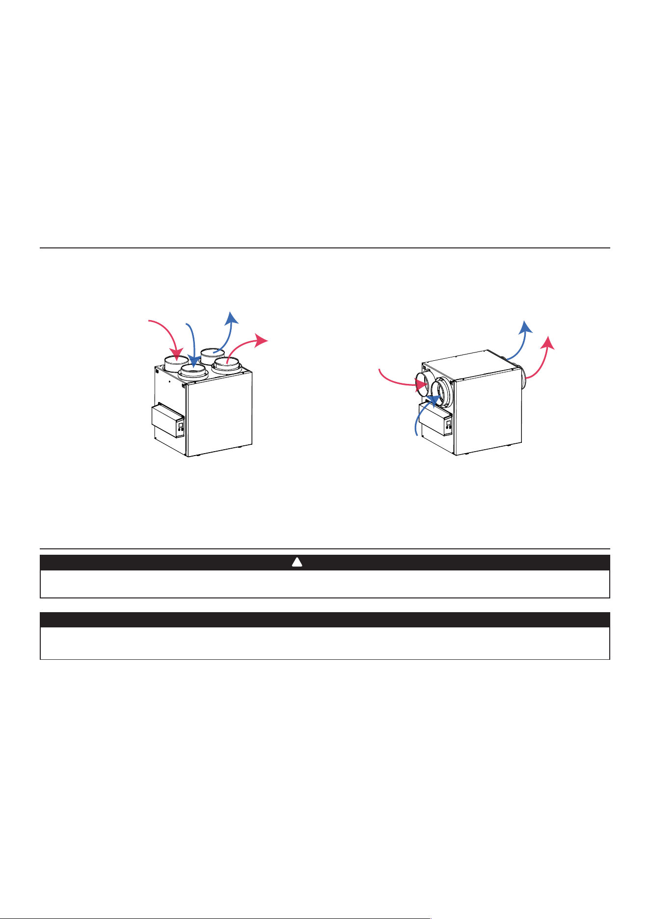
1.1 A
ir
d
isTribuTion
(n
ormAl
o
perATion
)
VF0077
NOTE:Thedimensions,performancechartsandspeci�cationsarelistedonthespeci�cationsheetsoftheunit.
Visit our website at venmar.ca or vanee.ca.
2. INSTALLATION
2.1 l
ocATinG
And
m
ounTinG
THe
u
niT
The wearing of safety glasses and gloves is recommended when installing, maintaining or cleaning the unit to
reducetheriskofinjurythatcouldbecausedbythepresenceofthinmetaland/orhighmovingparts.
WARNING
!
Stale air
from
building
Fresh air
from
outdoors
Fresh air to
building
Stale air
to
outdoors
Stale air
from
building
Fresh air
from
outdoors
Fresh air to
building
Stale air
to
outdoors
Choose an appropriate location for the unit:
• Within an area of the house where the ambient temperature is kept between 10°C (50°F) and 65°C (149°F);
• Away from living areas (dining room, living room, bedroom), if possible;
• So as to provide easy access to the interior cabinet for maintenance, and to the control panel on the side of the unit;
• Closetoanexteriorwall,soastolimitthelengthoftheinsulatedexibleductstoandfromtheunit;
• HRV units only: close to a drain. If no drain is close by, use a pail to collect run-off;
• Awayfromhotchimneys,electricalpanelandother�rehazards;
• Within 6 feet of a power source (standard outlet).
Consumer Information
A.ToensurequietoperationoftheENERGYSTARcerti�edH/ERV,eachproductmodelmustbeinstalledusingsound
attenuation techniques appropriate for the installation.
B.Thewayyourheat/energy-recoveryventilatorisinstalledcanmakeasigni�cantdifferencetotheelectricalenergy
you use. To minimize the electricity use of the heat/energy-recovery ventilator, a stand-alone fully ducted installation is
recommended.Ifyouchooseasimpli�edinstallationthatoperatesyourfurnaceairhandlerforroom-to-roomventilation,
anelectricallyef�cientfurnacethathasanelectronicallycommutated(EC)variablespeedblowermotorwillminimize
your electrical energy consumption and operating cost.
C.Installationofauser-accessiblecontrolwithyourproductmodelwillimprovecomfortandmaysigni�cantlyreducethe
product model’s energy use.
Make sure that no piece of mineral wool will enter in the unit during installation. Otherwise, this could reduce
airowandgeneratevibrationsandnoiseintheunit.
CAUTION
5
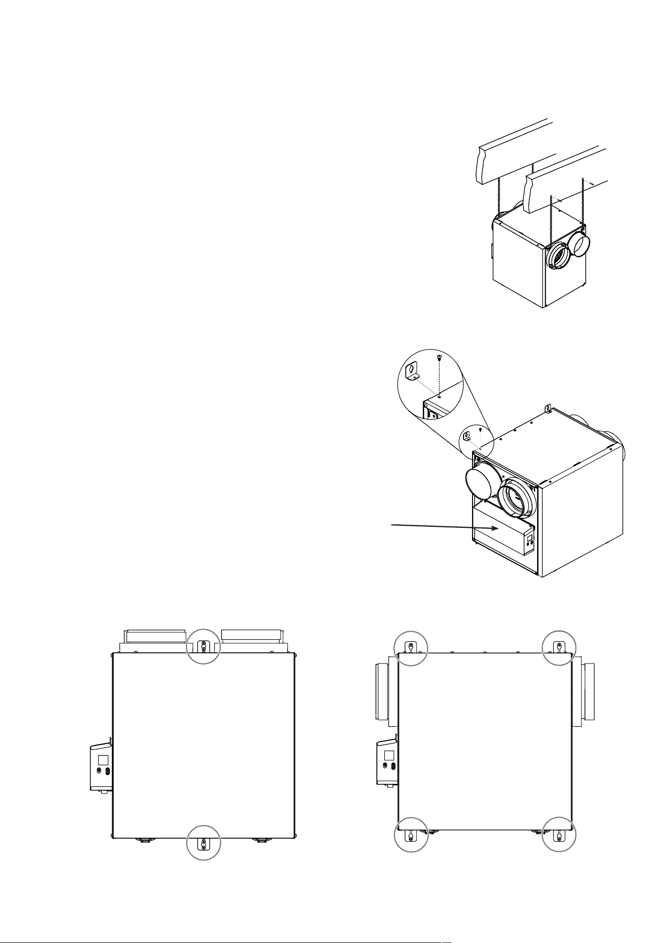
Suspended to the joists or trusts:
• Slightly bend the brackets on the unit to insert the provided chains.
• Hangtheunittothejoistsusingtheprovidedchains.Springsarenotrequired.
• Always make sure that the unit is no more than 1/4" off level.
OR
Wall mounted:
• Choose the appropriate location(s) for the mounting brackets
(see illustration below) according to stud(s) position.
• Insert the provided brackets under the unit frame (see illustration
hereafter).
• Fix the bracket using the screw no. 8 x 3/8".
• Using the 4 no. 8 x 1½" screws provided, secure the unit to the wall
making sure that the 4 screws engage into a stud.
• Always make sure that the unit is no more than 1/4" off level.
VD0485
2.1 l
ocATinG
And
m
ounTinG
THe
u
niT
(
conT
’
d
)
VD0488
VD0486
VD0487
INSTALLATION WITH 2 BRACKETS INSTALLATION WITH 4 BRACKETS
NOTE: Keep 3" clearance
on electrical box
side for cooling and
servicing.
6
VH0165
A
B
S
tale
air
from
building
:
• Install registers in areas where contaminants and humidity are
produced: kitchen, bathrooms, laundry room, etc.
• Install registers on an interior wall, 6 to 12 inches away from
the ceiling OR in the ceiling.
• Install the kitchen register at least 4 feet away from the range.
• Bathroom fans and range hoods can be used to better exhaust
stale air.
• Homes with more than one level require at least one exhaust
register at the highest level.
f
reSh
air
to
building
:
• Install registers in bedrooms, dining room, living room and
basement.
• Install registers in the ceiling OR high on the walls with the
airowdirectedtowardstheceiling.
• Ifaregistermustbeinstalledintheoor,directtheairowup
the wall.
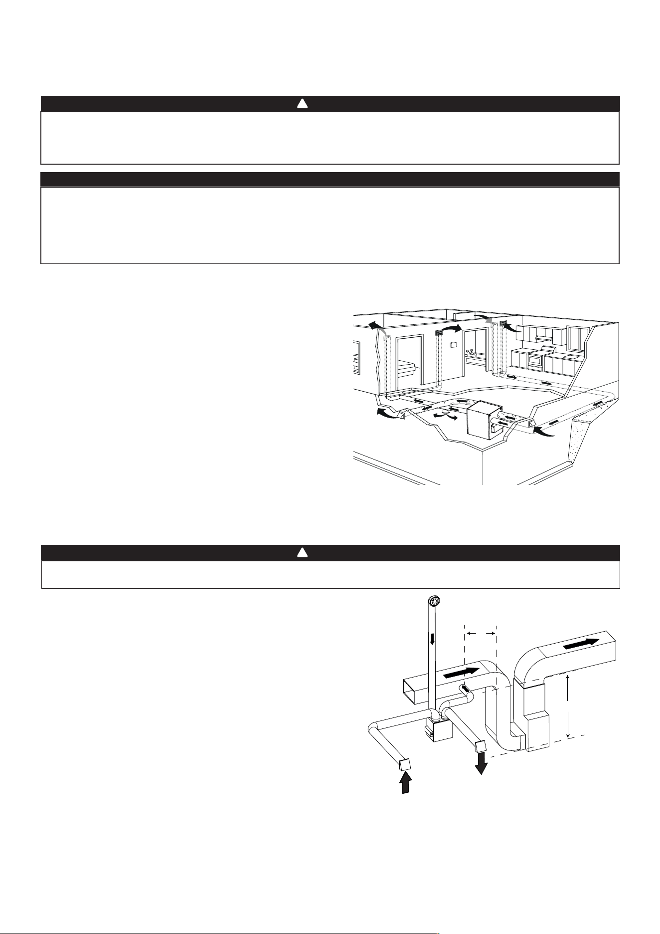
2.2.1 f
ullY
d
ucTed
s
YsTem
(T-1) (T
His
confiGurATion
Allows
recirculATion
mode
To
operATe
.)
2.2 i
nsTAllinG
THe
d
ucTwork
And
THe
r
eGisTers
Never install a stale air exhaust register in a room where there is a combustion device, such as a furnace, gas
waterheater,�replaceoranyapplianceorequipmentthatcangenerategaseouscontaminants,orpollutants.
The negative pressure this could create in the room may impair proper evacuation of the gas or pollutants,
which may have severe health consequences.
WARNING
!
S
tale
air
from
building
:
Same as for Fully Ducted System, described on point 2.2.1.
f
reSh
air
to
building
:
• Connect the fresh air distribution duct of the unit to the central
forced-air system return duct at least 10 feet away from the
central forced-air system (A+B)*.
* This 10-ft. distance applies only in areas where the outside
temperature falls below the freezing point 0°C (32°F).
NOTE: The central forced-air system blower operation can be
synchronized with the unit (see Section 3.3). It is recommended, but
not essential that the central forced-air system blower runs when
the unit is in operation.
2.2.2 e
xHAusT
d
ucTed
s
YsTem
(T-2) (T
His
confiGurATion
Allows
recirculATion
mode
To
operATe
.)
Duct connection to the central forced-air system can be regulated by some codes and standards. It is your
responsibility to consider and comply with your local requirements to avoid any non-compliance.
WARNING
!
NOTE:Forthistypeofcon�guration,theT-1optionmustbeselectedontheLCDscreenwhenauto-balancingtheunit.
NOTE:Forthistypeofcon�guration,theT-2optionmustbe
selectedontheLCDscreenwhenauto-balancingtheunit.
Stale air from
bathroom
Fresh air to
building
Stale air to
outdoors
Fresh air from
outdoors
If ducts have to go through an unconditioned space (e.g.: attic), always use insulated ducts to prevent condensation
formation inside and outside ducts, which could cause material damage and/or mold growth. Moreover, if
fresh air to building duct and/or stale air from building duct goes/go through an unconditioned space, the unit
must be set to operate continuously in cold conditions (below 10°C/50°F). Continuous air movement inside
ducts will prevent condensation formation. The unit can be stopped temporarily for maintenance and/or repair
purposes in such conditions.
CAUTION
A+b=
min
10’
7
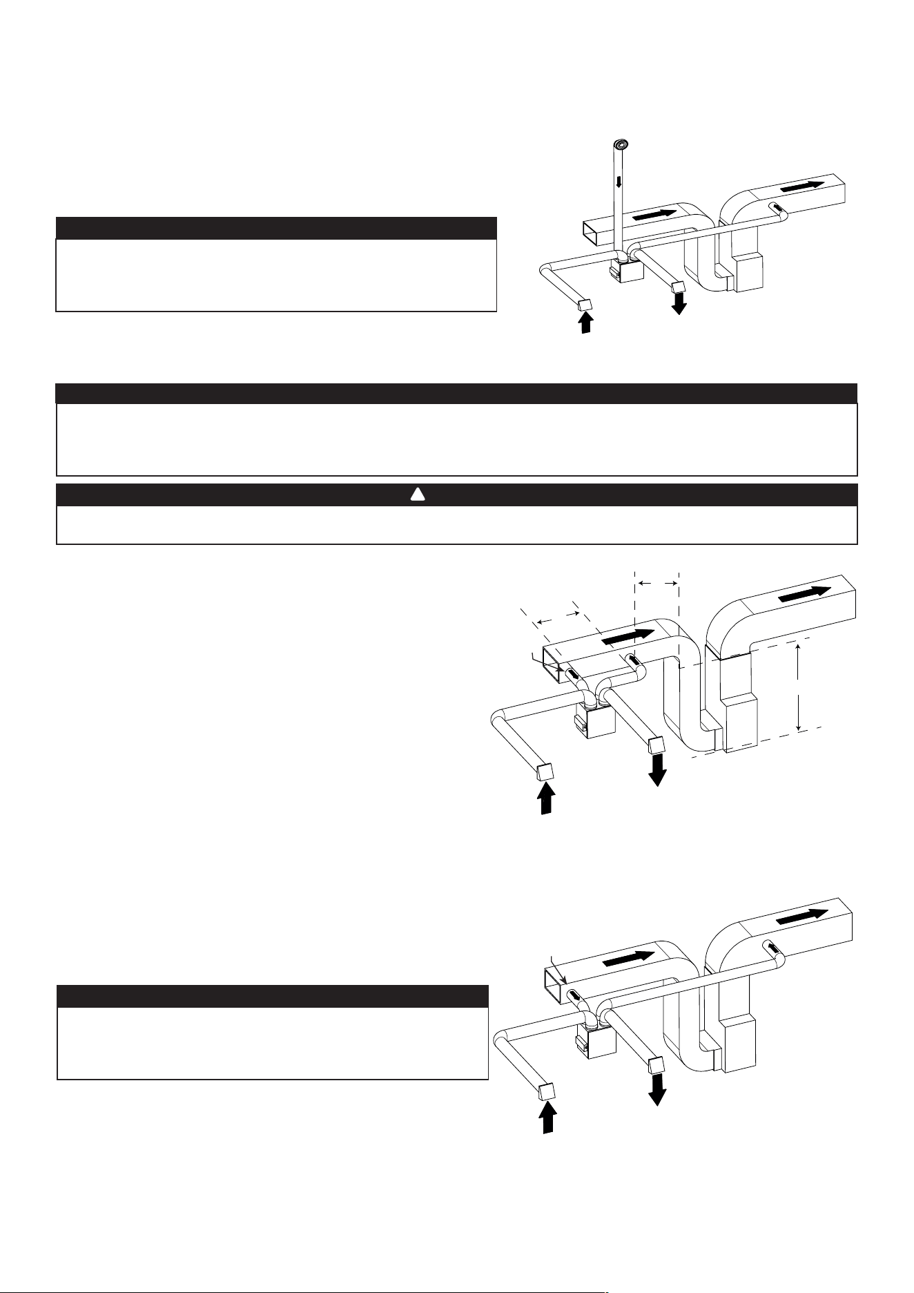
2.2.3 s
implified
i
nsTAllATion
(T-4) (T
His
confiGurATion
does
noT
Allow
recirculATion
mode
To
operATe
.)
The central forced-air system must be synchronized with the unit since fresh air evacuation and distribution
come from the same section. The central forced-air system must operate to avoid fresh air to be directly
drawnbytheevacuation,whichwouldreducesigni�cantlyfreshairsupplytothebuilding.SeeSection3.3
for ducting.
CAUTION
Duct connection to the central forced-air system can be regulated by some codes and standards. It is your
responsibility to consider and comply with your local requirements to avoid any non-compliance.
WARNING
!
VH0168
Fresh air and exhaust air ow through the central forced-air
systemducts,whichsimpli�estheinstallation.
The use of bathroom fans and a range hood is suggested to
exhaust stale air.
S
tale
air
from
building
:
Connect the stale air intake port of the unit to the central forced-
air system return duct at least 3 feet ahead of the fresh air
distribution from the unit.
f
reSh
air
to
building
:
Connect the fresh air distribution duct of the unit to the central
forced-air system return duct at least 10 feet away from the
central forced-air system (A+B)*.
* This 10-ft. distance applies only in areas where the outside
temperature falls below the freezing point 0°C (32°F).
VH0167
C
B
A
A+b=
min
10’
c=3’
A
lTernATe
insTAllATion
(T-5) (T
His
confiGurATion
does
noT
Allow
recirculATion
mode
To
operATe
.)
Unit should be synchronized with central forced-air system
operation to avoid condensation and mold growth in central
forced-air system distribution ducting if cooling mode of central
forced-air system is used.
Fresh air
to building
Stale air from
building
Stale air to
outdoors
Fresh air from
outdoors
Thiscon�gurationisnotrecommendedwithhighvelocity
central forced-air system. High pressures produced by
these systems could affect unit proper operation and
generate errors.
CAUTION
NOTE:Forthistypeofcon�guration,theT-5optionmustbe
selectedontheLCDscreenwhenauto-balancingtheunit.
Stale air to
outdoors
Fresh air from
outdoors
Fresh air to
building
Stale air from
building
NOTE:Forthistypeofcon�guration,theT-4optionmustbe
selectedontheLCDscreenwhenauto-balancingtheunit.
VH0166
A
lTernATe
insTAllATion
(T-3) (T
His
confiGurATion
Allows
recirculATion
mode
To
operATe
.)
Unit should be synchronized with central forced-air system
operation to avoid condensation and mold growth in central forced-
air system distribution ducting if cooling mode of central forced-air
system is used.
Thiscon�gurationis notrecommendedwith highvelocity
central forced-air system. High pressures produced by these
systems could affect unit proper operation and generate
errors.
CAUTION
NOTE:Forthistypeofcon�guration,theT-3optionmustbe
selectedontheLCDscreenwhenauto-balancingtheunit.
Stale air from
bathroom
Fresh air to
building
Stale air to
outdoors
Fresh air from
outdoors
8
2.3 c
onnecTinG
THe
d
rAin
(Hrv o
nlY
)
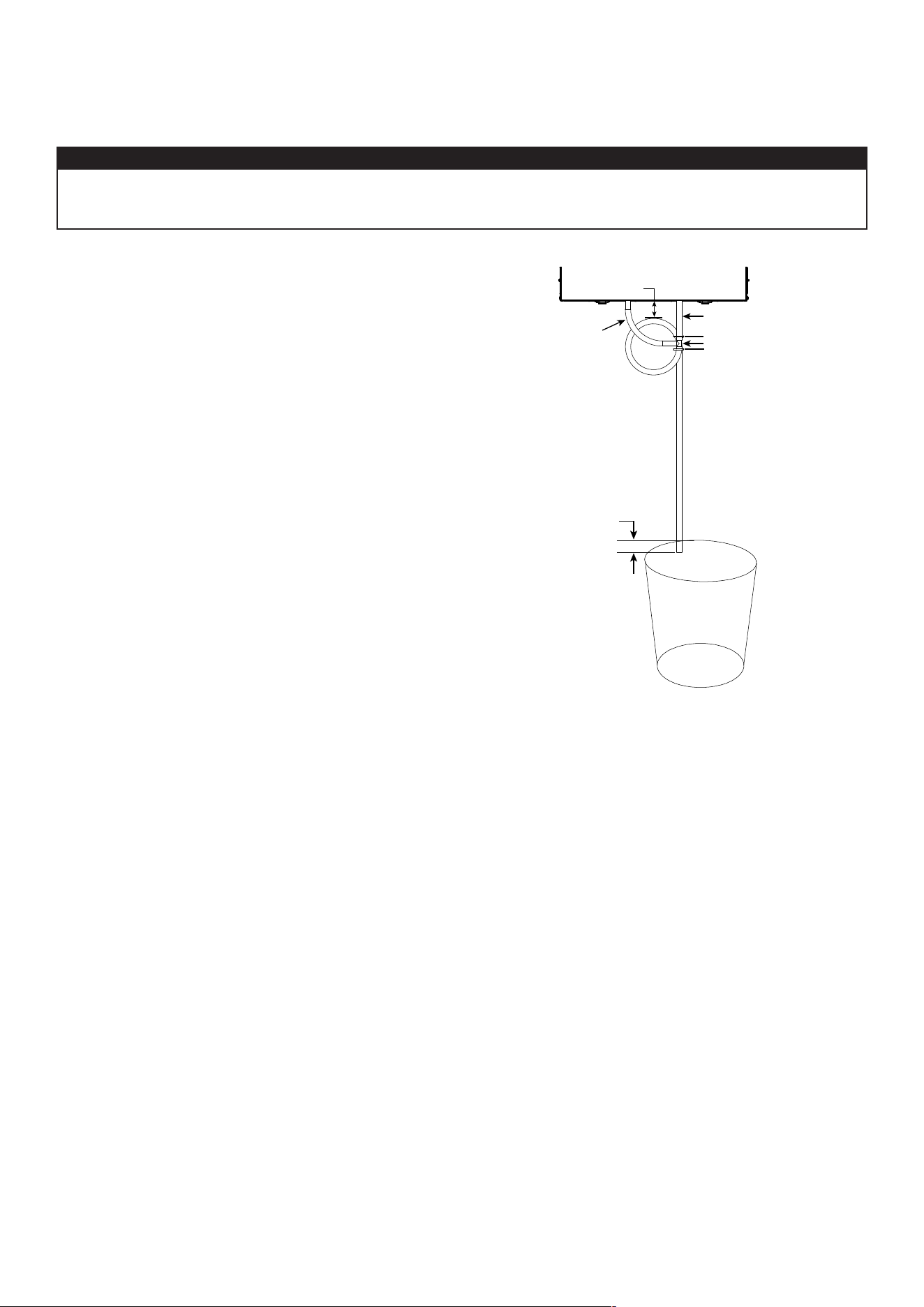
Install the drain hose included and run it to a drain or a pail. This unit may generate a large amount of water
in cooler weather. It is necessary to install the drain hose properly to prevent water damage and/or material
damage.
CAUTION
• Cut the appropriate length of drain tubing (see illustration
at right).
• Connect the tubing to the provided adaptor.
• Make a water trap loop in the tube to prevent the unit
from drawing unpleasant odors from the drain source.
• Add water in the loop to prevent noise or hiss.
• Make sure there is a distance of at least 2" between the
unit and the tubing loop (see illustration at right).
• Using tie wraps provided, attach the tubing as illustrated.
• Runthetubetotheoordrainortoanalternatedrain
pipe or pail.
• IMPORTANT: If using a pail to collect water, place the tube
end approximately 1" inside the pail in order to prevent
water from being drawn back up into the unit.
≥
2"(51 mm)
±
1"(25 mm)
5 1/4" (133 mm)
9 3/4" (248 mm)
T
VO0296
T
ie
w
rAp
T
ie
w
rAp
9
T
rAnsiTioninG
To
8-
in
.
ducTs
If using 8-in. ducts, install 6-in. to 8-in. transitions on the ports, and secure using duct tape only. If rigid ducting is used,
installa12-in.sectionofexibleductbetweenthetransitionandtherigidducting(seeabove).
r
iGid
ducTs
Topreventpotentialwaterleakageincoldsiderigidductinginsulation,sealallrigidductingjointswithducttape.
Toavoidtransmissionofvibrations,alwaysusea12-inchsectionofexibleducttoconnectrigidductstotheunit.To
connectinsulatedrigidductstotheunit(coldside)usinginsulatedexibleducts,followinstructionsinsection2.4.To
connectregularrigidducts(warmside)totheunitusingnon-insulatedexibleducts,useatiewrap.
2.5 c
onnecTinG
THe
d
ucTs
To
THe
u
niT
i
nsulATed
flexible
ducTs
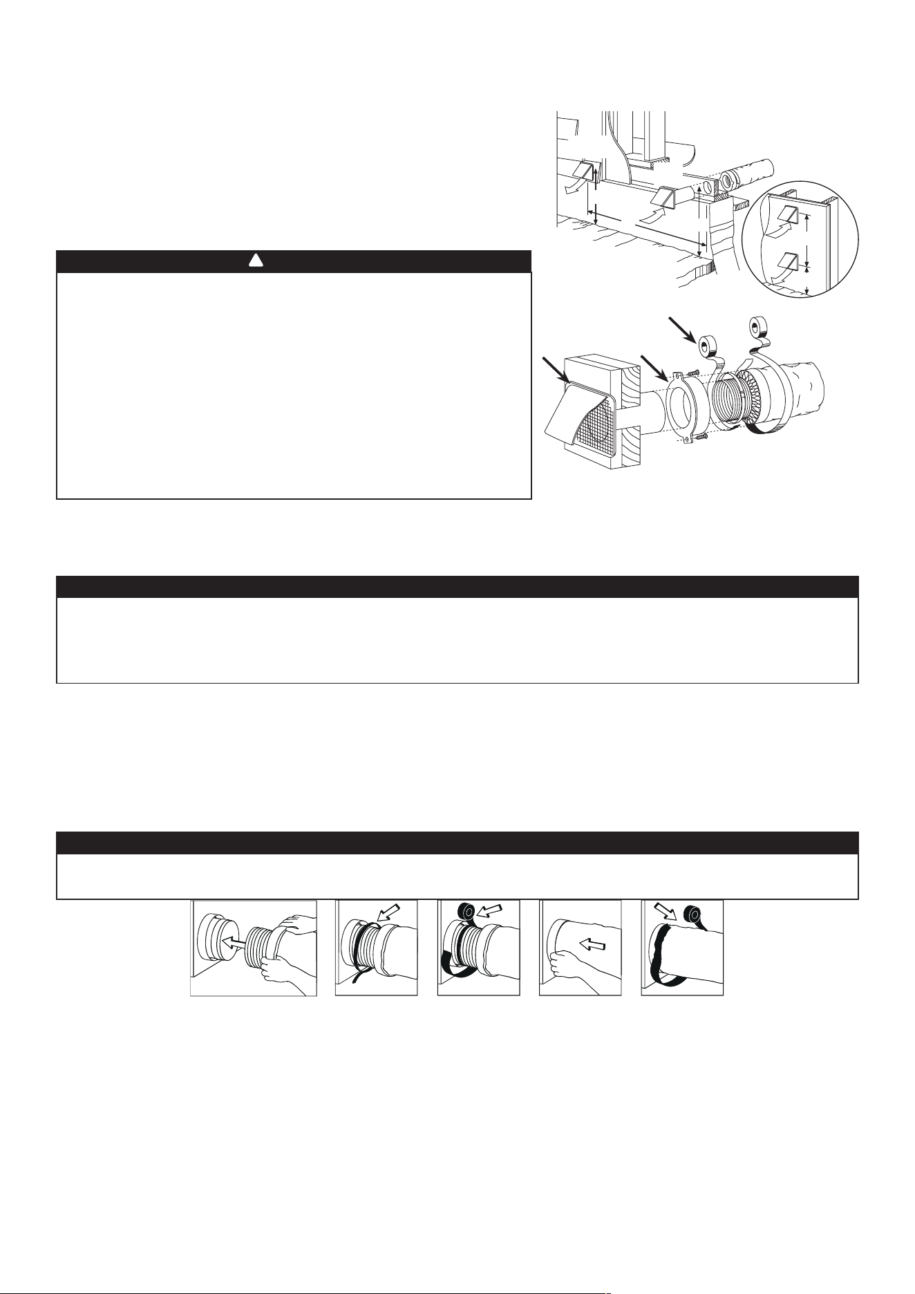
Usethefollowingproceduretoconnecttheinsulatedexibleductstotheportsoftheunit(exhausttooutsideandfresh
air from outside).
1. Exposetheexibleductbypullingbacktheinsulation,andplaceitover the inner port ring.
2. Attachtheexibleducttotheportusingatiewrap.
3. Sealthejointusingducttape.
4. Pulltheinsulationandvaporbarrieroverthejoint,tuckthembetweentheinnerandouterrings of the double collar and
fasten them in place using duct tape.
VJ0157
• If ducts have to go through an unconditioned space (e.g.: attic), always use insulated ducts to prevent
condensation formation inside and outside ducts, which could cause material damage and/or mold growth.
• Do not use screws to connect the ducts or transitions to the ports so as not to interfere with ports
inner dampers operation. A non-functioning damper could freeze the unit, which could cause damages.
CAUTION
The vapor barrier should remain intact and free of cracks or openings. An opening could produce condensation
inside or outside duct, which could cause material damage and/or mold growth in the long run.
CAUTION
2.4 i
nsTAllinG
THe
e
xTerior
H
oods
To avoid cross-contamination:
• Keep at least 6 feet between both hoods.
• Install hood(s) at least at 18 inches away from the ground OR depth of
expected snow accumulation, whichever is greater.
Refer to illustration above for proper connection
method of the insulated ducts to the hoods. An
“Anti-Gust Intake Hood” should be installed in
regions where a lot of snow is expected to fall.
VD0028
e
xHAusT
H
ood
*
i
nTAke
H
ood
18”
18”
6’
6’
18”
o
pTionAl
ducT
locATion
T
Ape
And
ducT
Tie
c
AulkinG
Make sure intake hood is at least 6 feet (1.8 m) away from any
of the following:
• Dryerexhaust,highef�ciencycentralforced-airsystemvent,
central vacuum vent
• Gas meter exhaust, gas barbecue-grill
• Any exhaust from a combustion source
• Garbage bin and any other source of contamination.
Ignoringtheserecommendationscouldsigni�cantlydegradethe
quality of the incoming air which, in some cases, could result in
health consequences.
In the event of a conict between our conditions and local
requirements, the latter will have priority.
WARNING
!
NOTE:Itisrecommendedtouse8"ductinginsteadof6"ductingifrequiredairowisover200CFMandlongrunof
ductingorhighquantityofelbowsisused.Itwillpreventhavingtoohighstaticpressureintheducting.
c
AulkinG
*Do not install exhaust hood with non-return
damper since it can freeze in winter.
10
2.5.1 d
ucTs
c
onnecTion
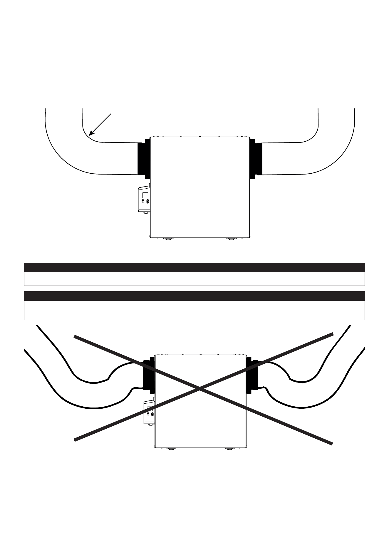
VD0489
C
orreCt
inStallation
VD0490
i
nCorreCt
inStallation
IMPORTANT: Makesuretoconnectductingasillustratedbelowtogetairowsreadingaccuracy.Correct
installation will also allow proper drainage of water that may accumulate in ducting.
Insulated ducts must have the same diameter as the ports to ensure proper drainage of water that may
accumulate in ducts.
CAUTION
Ductingmustnotbetoocrushed.Otherwise,airowsreadingaccuracywillbeaffected.
CAUTION
R = 3" minimum
NOTE:Routeductsasstraightaspossible,minimizethenumberofelbowsanddesignandinstallductsinaccordancewith
HRAIbestpractices.
11
3.CONNECTIONS
3.1 e
lecTricAl
c
onnecTion
To
o
pTionAl
m
Ain
w
All
c
onTrol
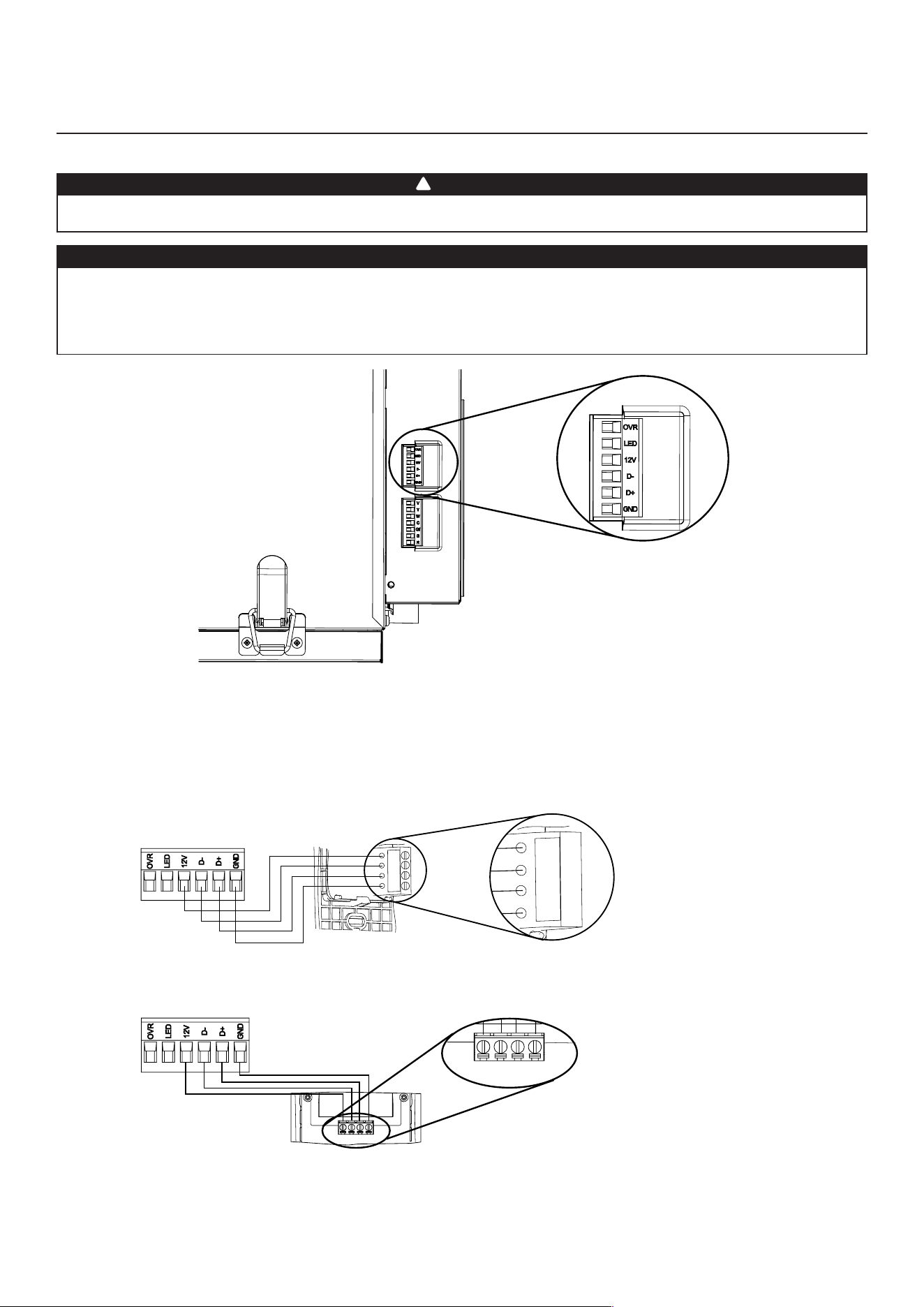
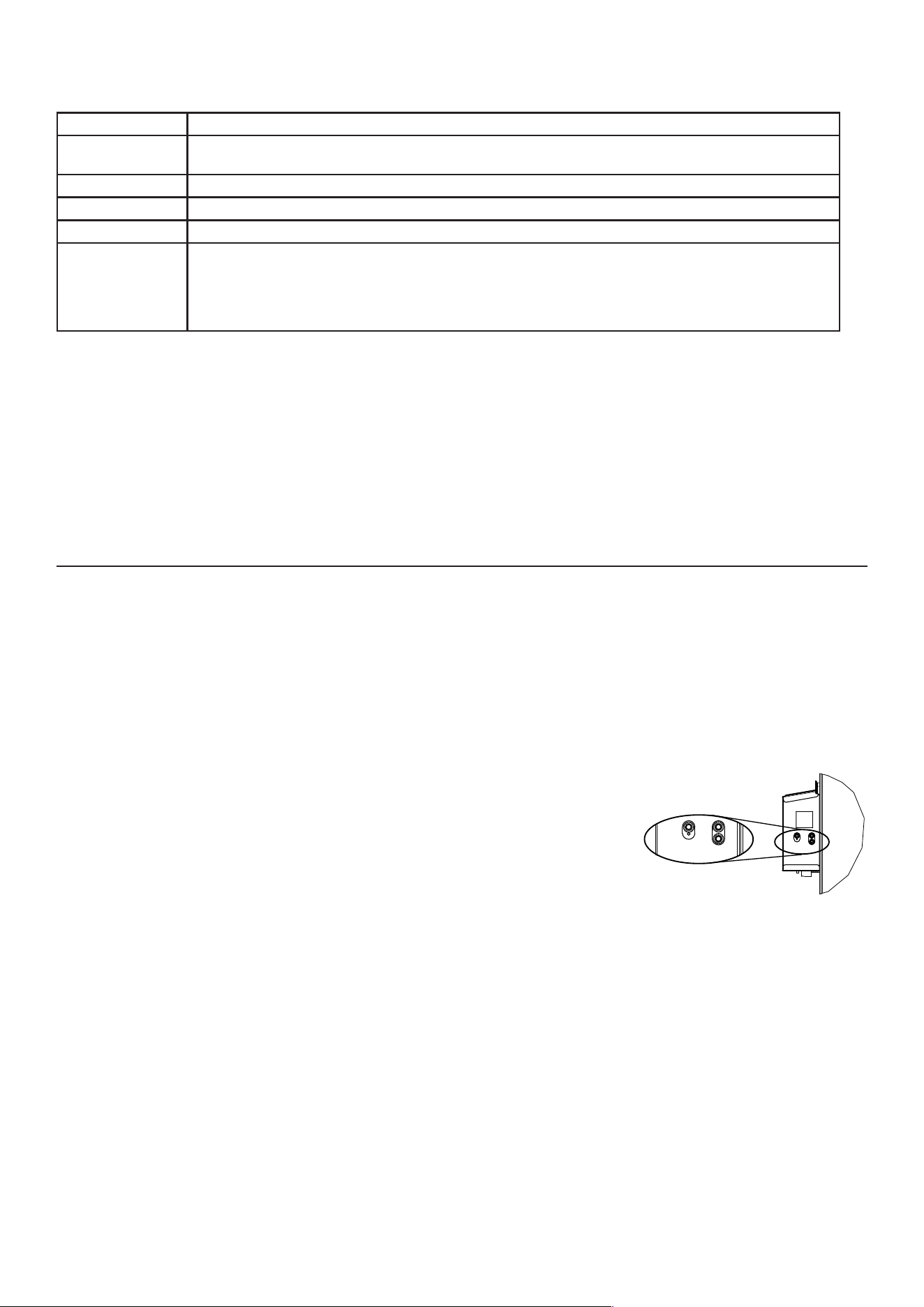
Use the terminal connector included to perform the electrical connection for optional main wall control. Check if all wires are
correctlyinsertedintheircorrespondingholesintheterminalconnector.Usescrewsto�xwiresintheterminalconnector.
3.1.1 e
lecTricAl
c
onnecTion
To
d
eHumidisTAT
or
A
uTomATic
o
pTionAl
m
Ain
w
All
c
onTrol
Gnd
D+
12V
D-
VC0241
12V
D-
D+
Gnd
Once the wall control connections have been made, insert the terminal connector in the electrical compartment.
NOTE : For information about the operation of the wall control, refer to the corresponding Installation and User Guide, available at
vanee.ca or venmar.ca.
Always disconnect the unit before making any connections. Failure to cut power could result in electrical shock
or damage to the wall control or electronic module inside the unit.
Never install more than one optional main wall control per unit. Make sure that the wires do not short-circuit
between themselves or by touching any other components on the wall control. Avoid poor wiring connections.
To reduce the risk of electrical interference (noise), do not run wall control wiring next to control contactors or
near light dimming circuits, electrical motors, dwelling/building power or lighting wiring or power distribution
panel.
CAUTION
WARNING
!
HD0491
u
niT
b
oTTom
v
iew
T
erminAl
c
onnecTor
3.1.2 e
lecTricAl
c
onnecTion
To
A
dvAnced
o
pTionAl
m
Ain
w
All
c
onTrol
12V D- D+ Gnd
VC0242
12V D- D+ Gnd
12
3.CONNECTIONS(CONT’D)
3.2 e
lecTricAl
c
onnecTion
To
o
pTionAl
A
uxiliArY
w
All
c
onTrol
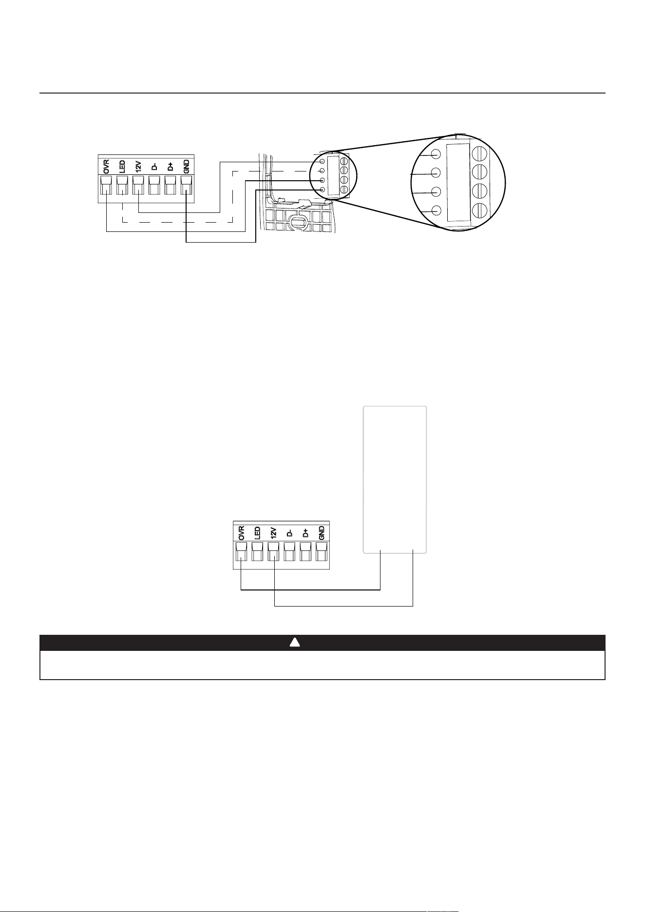
3.2.1 e
lecTricAl
c
onnecTion
To
20-40-60 o
pTionAl
A
uxiliArY
w
All
c
onTrol
Gnd
OVR
12V
LED
VC0243
Gnd
OVR
12V
LED
Whencon�guratingOVRoptionontheLCDscreen,chooseamongthese3con�gurations:BAL(theunitremainsbalanced
whileprovidingmaximumairow),PER(theunitisslightlyunbalancedsincethedistributionmotorisinMAXspeedwhile
allowing maximum exhaust ventilation) and DIS (the unit is unbalanced since air distribution is constant despite a higher
need in exhaust ventilation).
NOTE : The auxiliary wall control can be used with a 3-wire connection by removing the LED signals. This optional wiring
will not allow an installation with more than 1 auxiliary wall control to properly synchronize their LEDs on an event
requested from a peer. Only the auxiliary wall control having requested the timer event will have the LEDs updated
accordingly.
3.2.2 e
lecTricAl
c
onnecTion
To
d
rY
c
onTAcT
o
pTionAl
A
uxiliArY
w
All
c
onTrol
(
e
.
G
. c
rAnk
T
imer
)
Crank Timer
or
Any Dry Contact
12VOVR
VC0256A
A miswiring that sends a 24 VAC signal to the 6-position terminal block (OVR, LED, 12V, D-, D+, GND) could
permanently damage the control circuit. Verify carefully wire connections before powering-up the unit.
WARNING
!
13
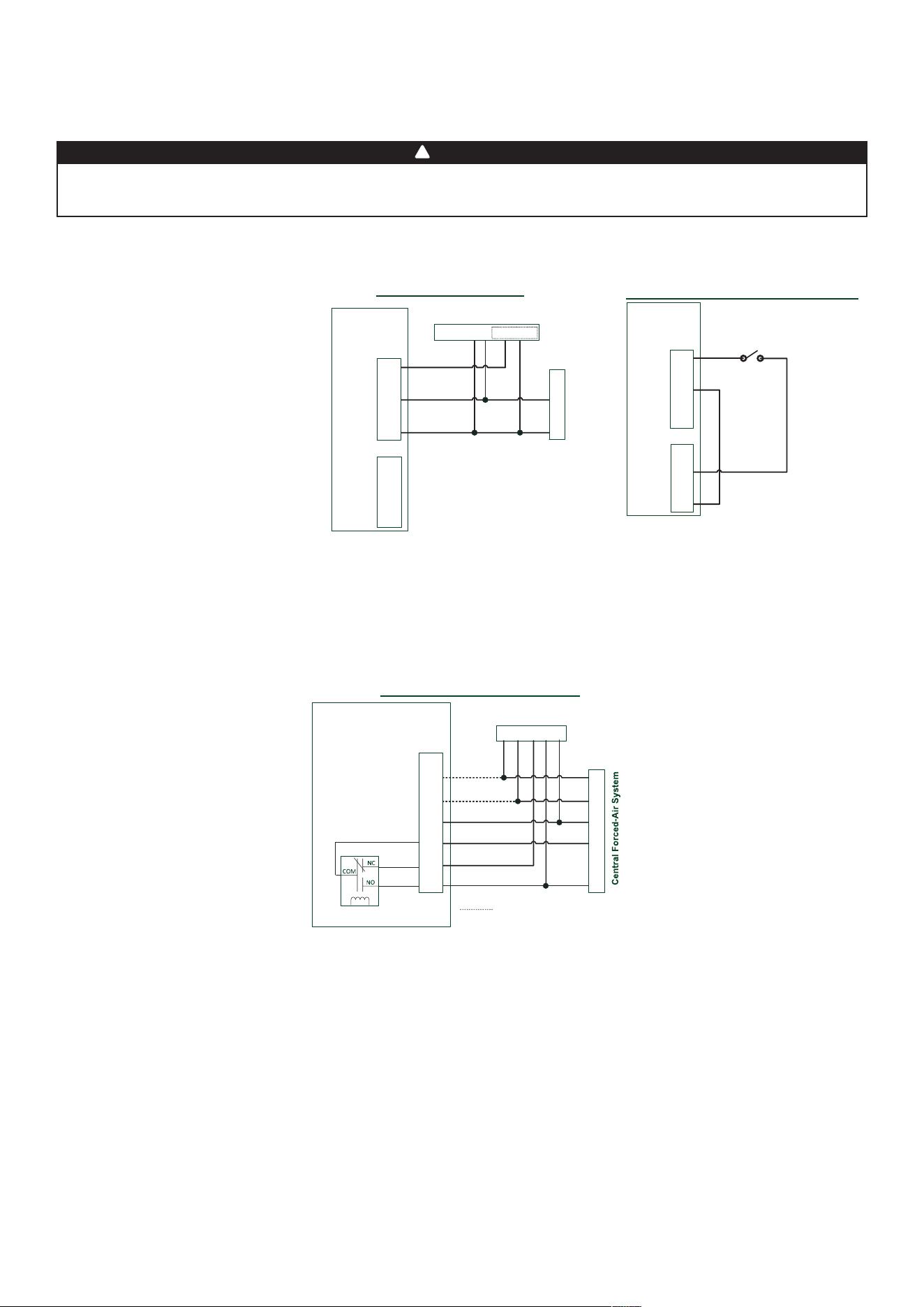
The Virtuo technology allows synchronizing the unit operation with the central forced-air system operating time. It
prevents unnecessary central forced-air system operating time while providing a better air distribution.
To use this function, W and Y connections must be added to R and C connections to inform the unit that the central
forced-air system is running (refer to dotted lines in above diagram).
Never connect a 120-volt AC circuit to the terminals of the central forced-air system interlock (standard
wiring). Only use the low voltage class 2 circuit of the central forced-air system blower control. The unit is
designed for low voltages only. Connecting the unit on 120-volt circuit would damage it instantly.
WARNING
!
3.3 c
onnecTion
To
THe
c
enTrAl
f
orced
-A
ir
s
YsTem
Air Exchanger PCB
Terminal Blocks
Y
W
C
G
R
Y W G R C
Central Forced-Air System Thermostat
Wiring Options with Central Forced-Air System
Vent
Y
W
C
Gf
G
R
J13
Internal
Logic
Optional Wiring for Synchronization
3.3.1 u
niT
o
perATion
u
sinG
A
d
rY
c
onTAcT
c
onnecTion
3.3.2 u
niT
i
nTerconnecTion
wiTH
c
enTrAl
f
orced
-A
ir
s
YsTem
(r/c/G/G
f
)
These connections must be done if you want the unit to force the central forced-air system blower operation when
ventilating (refer to solid lines in above diagram).
NOTE: Theseconnectionsarerequiredforinstallationcon�gurationT-4.Refertosection2.2formoredetails.
3.3.3 s
YncHronizATion
wiTH
c
enTrAl
f
orced
-A
ir
s
YsTem
f
uncTion
Y
W
C
G
R
Y W G R C Acc+ Acc-
Central Forced-Air System Thermostat
Central Forced-Air System
Wiring for Dry Contact Connection
1
1- External switch or any Dry-contact can be used to
activate Vent input if not available on the Thermostat
Air Exchanger
Terminal Blocks
Alternate Wiring for Dry Contact Independent Installation
Vent
Y
W
C
Gf
G
R
J13
OVR
LED
12V
D-
D+
GND
J9
External Switch or any
alternate Dry-Contact
Air Exchanger
Terminal Blocks
Vent
Y
W
C
Gf
G
R
J13
OVR
LED
12V
D-
D+
GND
J9
Note : Synchronization with a central forced-air system
with W and Y is not available with this configuration.
1 - External switch or any dry contact can be used to activate vent input if not
available on the thermostat. Some thermostats offer a single wire 24VAC output
for accessory ventilation. It can be directly connected to vent input and therefore
the Acc- / R connection is not required.
This unit can be controlled by any dry contact connection such as the thermostat equipped with an optional ventilation output.
Once wired, unit will toggle between
the Standby mode when contact is
opened and the selected mode when
contact is closed. Choose among these 4
con�gurations:minimum(unitoperating
in MIN speed), intermittent (unit
operating in MIN speed 20 min/hr then
asperINTcon�gurationselectionfor
40 min), auto* (unit operating according
to outdoor temperature) and maximum
(unitoperatinginMAXspeed)inDRY
option on the LCD screen when the VENT
contact is activated. Refer to section 5
for more details.
* In auto mode, the unit will operate as
follows:
• Less than -25°C = 10 min/hr
• -25°C to -7°C = 20 min/hr
• -7°C to 10°C = 40 min/hr
• 10°C to 25°C = MIN speed
• 25°C to 28°C = 30 min/hr
• 28°C to 33°C = 20 min/hr
• Above 33°C = 10 min/hr
NOTE : This dry contact option will override the main wall control so we do not
recommend the use of a wall control with this type of connection.
NOTE:Followingductinginstallationcon�gurationandtemperatureconditions,it
may be necessary for the unit to operate continuously. Refer to section 2.2
for more details.
14
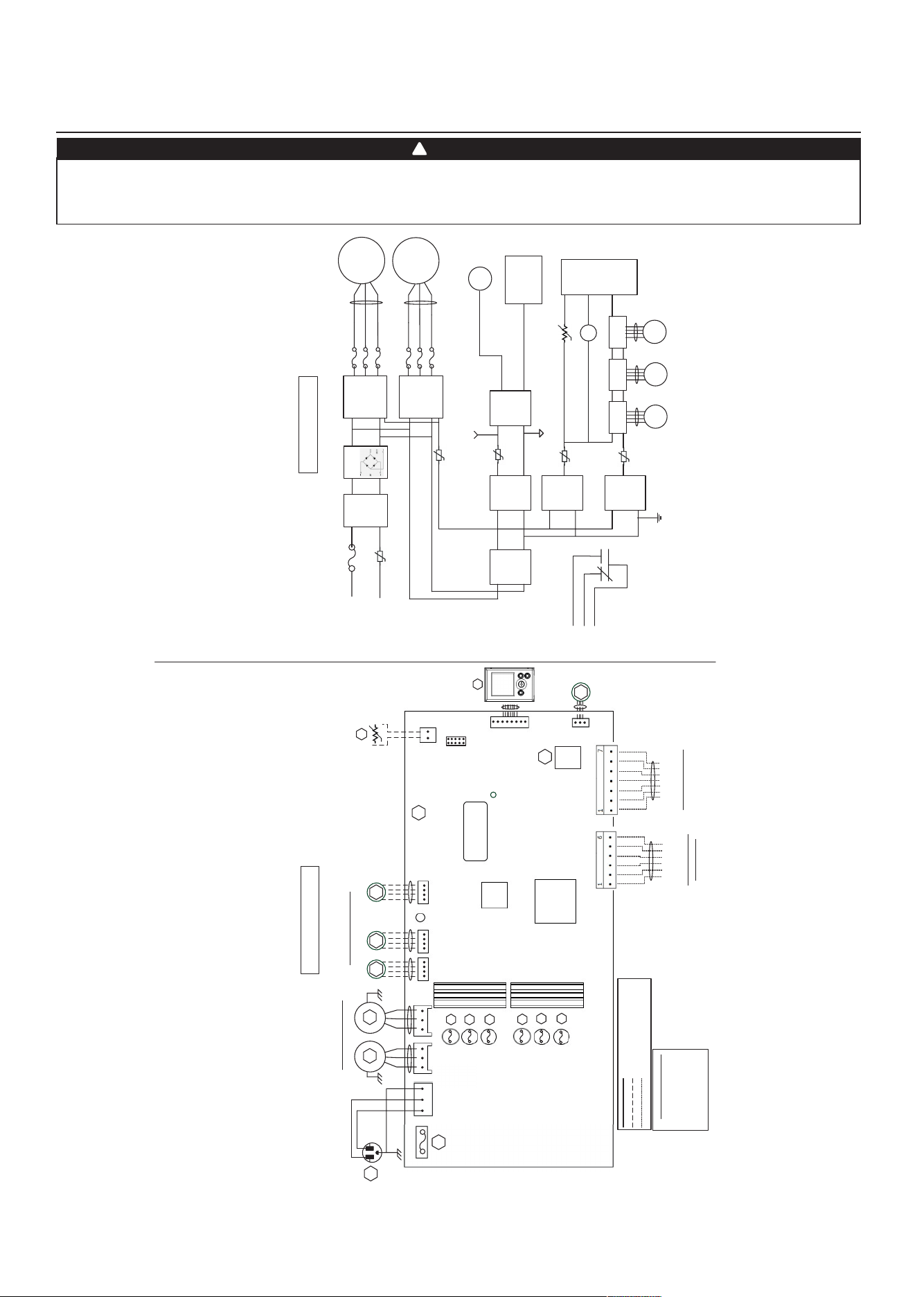
4.WIRINGDIAGRAM
BLK
BLK
GRN
LOGIC DIAGRAM
WIRING COLOR CODE
BLK BLACK
BLU BLUE
GRN GREEN
RED RED
WHT WHITE
Line voltage factory wiring
Low voltage factory wiring
Low voltage field wiring
(Exhaust)
BLU
RED
12
0VAC
60Hz
W1
GRN
1
Power
LED
J1
M3
Damper Stepper Motors
Y
M1
WHT
BLK
A1
MAIN ELECTRONIC
ASSEMBLY
M1
Power
Supply
(15VDC)
Line
Neutral
K1
G
Gf
AC
Line
Filter
J1-2
F1
High Voltage
(120VAC)
J1-1
To J2
MCU
K1
M3
Stepper
Driver
To J5
WIRING DIAGRAM
BDM
1
J2 J3 J5 J6
J7
1
1 1 1
1
J7a
J15a
1
A2
LCD
ASSEMBLY
GRN
Venlaon Fan Motors
BLU
RED
M2
M4 M5
(Supply)
(Supply )
(Recirc) (Exhaust)
MCU
Seria l Numbe r
Isolaon
Transformer
Motor Fuses
F3
F6
F5
F7
V W GfC G R
* Oponal AHU Wiring
(Isol ated 24VAC)
OVR
LED
12V
D-
D+
GND
Main and Auxilliary
Controls Wiring
Thermistor
R1
RT1
(NTC)
Bridge
IPM
Motor 1
IPM
Motor 2
F3
F2
M2
To J3
F
F4
AHU
Relay
K1
PTC3
Isolated
Supply
(12VDC)
Isolated
Supply
(3.3VDC)
J9
J13
Logic
Supply
(3.3VDC)
PTC2
To J9
Logic
Supply
(12VDC)
M4
Stepper
Driver
To J6
M5
Stepper
Driver
To J7
PTC6
PTC4
To J13
R
TH1
To J7a
(R1)
LCD
Assembly
Isolated GND
Digital GND
To J15a
(A2)
J14
F2
F4
J16a
M6
Cooling
Fan
F7
F
M6
To J16a
F1
5A/125VAC
* 210-230 CFM
Mod els only
* 210-230 CFM
Mod els only
VE0481A
6
5
WARNING
• Risk of electric shocks. Before performing any maintenance or servicing, always disconnect the unit from its power source.
• This product is equipped with an overload protection (fuse). A blown fuse indicates an overload or a short-circuit situation.
If the fuse blows, unplug the product from the outlet. Discontinue using the unit and contact technical support.
!
15
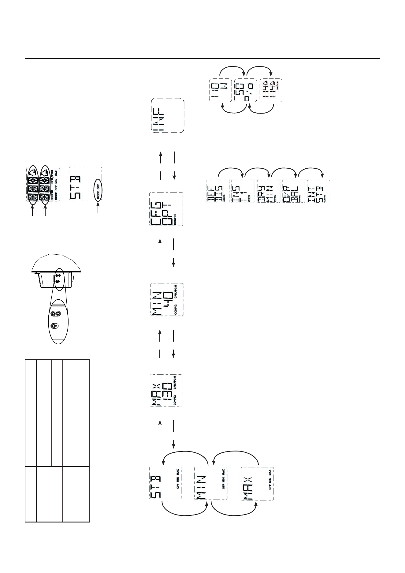
5.NAVIGATIONONLCDSCREEN
+
-
OK
VD0492
OK button Tocon�rmaselection.
+
button
To increase a value.
To scroll up in a selection.
-
button
To decrease a value.
To scroll down in a selection.
VQ0211
VQ0209
VQ021
0
VQ0203
VQ0212
Indicates current
mode
Indicates
freshairow
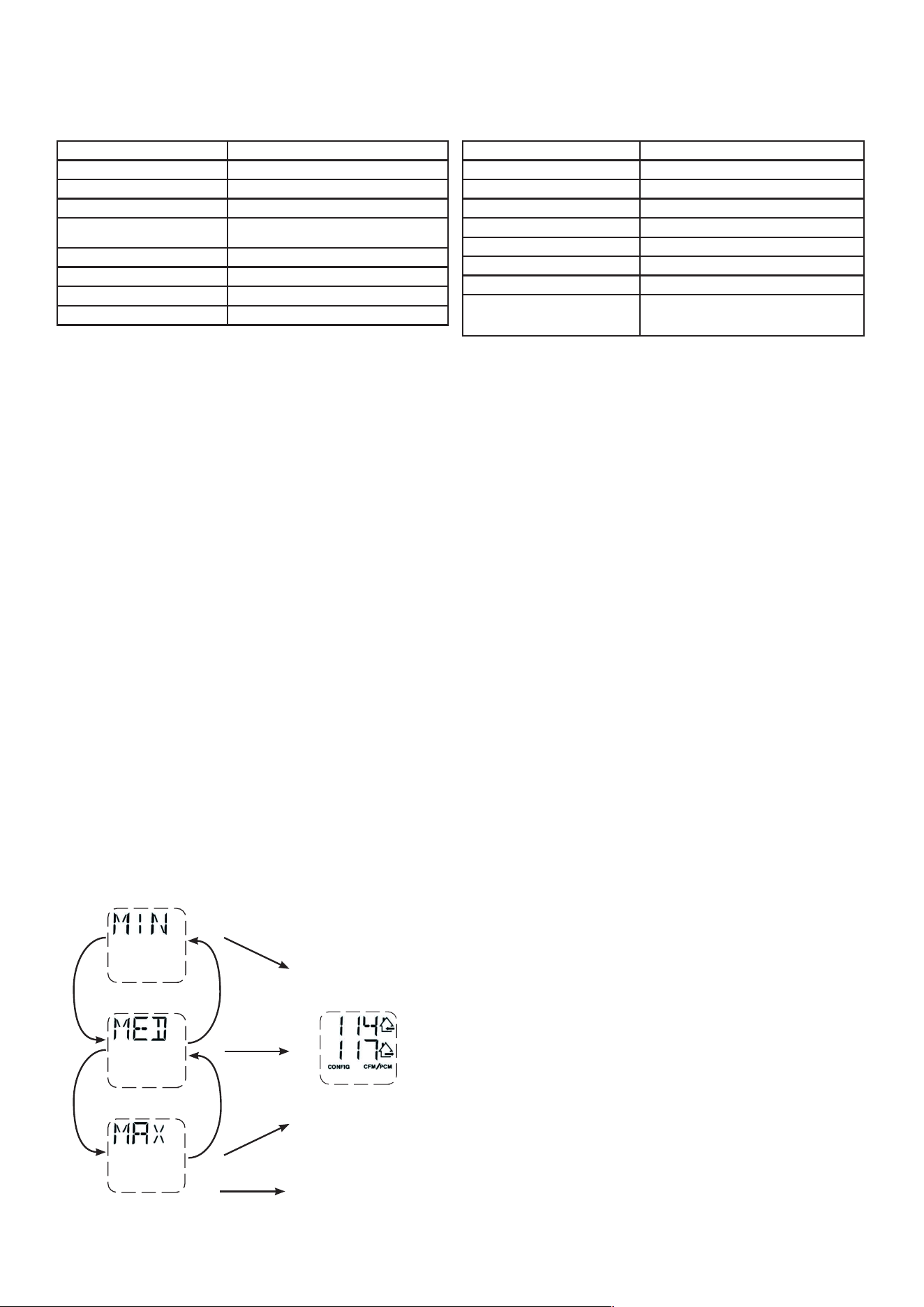
PRESS ON OK BUTTON TO
CHANGE THE OPERATING MODE.
USE + BUTTON OR - BUTTON
TO SELECT THE DESIRED
OPERATING MODE.
+
-
PRESS ON OK BUTTON TO
CONFIRM THE OPERATING
MODE SELECTION.
VQ0205
VQ0207
VQ0201
Indicates
staleairow
+
+
-
-
+
-
+
-
PRESS ON + BUTTON OR -BUTTONTOMODIFYMAXCFM,MINCFMOROPTIONSCONFIGURATION.
PRESS ON OK BUTTON DURING
4SECONDSTOMODIFYMAX
CFM CONFIGURATION.
MAXCFMDATAWILLFLASH.
USE + BUTTON TO INCREASE
VALUE OR - BUTTON TO
DECREASE VALUE.
PRESS ON OK BUTTON TO
CONFIRM VALUE.
PRESS ON OK BUTTON DURING
4 SECONDS TO MODIFY MIN
CFM CONFIGURATION.
MIN CFM DATA WILL FLASH.
USE + BUTTON TO INCREASE
VALUE OR - BUTTON TO
DECREASE VALUE.
PRESS ON OK BUTTON TO
CONFIRM VALUE.
PRESS ON OK BUTTON DU-
RING 4 SECONDS TO MODIFY
OPTIONS CONFIGURATION.
VQ0
19
7
VQ0202
VQ0
19
9
VQ0
19
8
VQ0200
FOR EACH
OPTION
CONFIGURATION,
USE + BUTTON
TO SCROLL UP
IN OPTIONS
AVAILABLE OR
- BUTTON TO
SCROLL DOWN
IN OPTIONS
AVAILABLE.
ONCE OPTION
SELECTION IS
DONE, PRESS
OK BUTTON
TO CONFIRM
SELECTION. THE
NEXTOPTION
CONFIGURATION
WILL THEN
DISPLAY.
VQ0213
+
-
PRESS ON OK BUTTON
DURING 4 SECONDS TO
ACCESS COMPLEMENTARY
INFORMATION.
VQ0214
VQ0215
VQ0216
+
+
-
-
DISPLAYS ELECTRICAL
POWER CONSUMPTION.
DISPLAYS UNIT %
RUNNING TIME
(PER HOUR)
FOR SELECTED
OPERATING MODE.
DISPLAYS UNIT
AIRFLOWS.
PRESS ON OK BUTTON TO
EXITCOMPLEMENTARY
INFORMATION.
NOTE:Accordingtounitmodelandcon�guration,somemenusmaynotbeavailable.
In the example above, the unit provides
114 CFM with a power consumption of
110 W during 50% of the hour. The net
airowis57CFM(50%X114),thenet
power consumption is about 55 W
(50%X110).
16
5.3 s
eTTinGs
m
odificATion
5.3.1 p
rocedure
To
m
odifY
min
cfm
s
eTTinG
• Go to MIN using (+/-) then press on the OK button for 4 seconds.
• Use(+/-)toincrease/decreaseCFMandOKtocon�rm.
5.3.2 p
rocedure
To
m
odifY
mAx
cfm
s
eTTinG
• GotoMAXusing(+/-)thenpressontheOKbuttonfor4seconds.
• Use(+/-)toincrease/decreaseCFMandOKtocon�rm.
5.3.3 p
rocedure
To
m
odifY
o
pTions
s
eTTinG
• Go to CFG OPT using (+/-) then press on the OK button for 4 seconds.
5.2 u
niT
f
irsT
b
ooT
p
repArATion
Follow these steps to ensure accurate measurements:
• Seal all the ductwork with tape. Close all windows and doors.
• Turn off all exhaust devices such as range hood, dryer and bathroom fans.
• If the installation is in any way connected to a ductwork of a central forced-air system, make sure that the central forced-air
system blower is ON. If not, leave central forced-air system blower OFF.
A
uTo
-b
AlAncinG
p
rocedure
• Plug the unit and wait for the maximum CFM to display on the LCD screen. If unit is colder than ambient temperature, it is
normal to experience a 60 s longer boot-up since motors have to preheat. Refer to section 8.1 if errors E22 or E32 display.
• ThemaximumCFMwilldisplayontheLCDscreen.Use(+/-)toadjusttheCFMandOKtocon�rm.
• TheminimumCFMwilldisplayontheLCDscreen.Use(+/-)toadjusttheCFMandOKtocon�rm.
• ThehousethatashesontheLCDscreenindicateswhichsidecurrentlylimitstheairow(supplyorexhaust).Iftheairow
reachedisnotsuf�cient,theinstallercanimprovetheinstallationtoincreaseairow.
i
nsTAllATion
c
onfiGurATion
s
elecTion
• INSwilldisplayontheLCDscreen.ChooseamongT-1,T-2,T-3,T-4orT-5followingtheinstallationcon�guration(Referto
section 2.2 for more details).
• Auto-balancing is completed.
5.1 lcd s
creen
DISPLAY DEFINITION
STB Standby mode
MED MED speed
INT Intermittent mode
REC Recirculation mode
(Min, Med or Max speed)
AUT AUTO mode
SMT SMART mode
OVR 20 Override 20 min
OVR 40 Override 40 min
5.3.4 p
rocedure
To
m
odifY
i
ndependenT
A
irflows
s
eTTinG
• Press simultaneously (+/-) buttons for 4 seconds.
VQ0217
VQ0218
VQ0219
VQ0220
+
+
-
-
OK
O
K
O
K
+
WHENMAXDISPLAYS,PRESS
ON
+
BUTTONTOEXIT
INDEPENDENT AIRFLOWS
SETTING.
SUPPLY AIRFLOW VALUE WILL FLASH.
PRESS ON + BUTTON OR - BUTTON TO
INCREASE/DECREASE VALUE.
PRESS OK BUTTON.
EXHAUSTAIRFLOWVALUEWILLFLASH.
PRESS ON + BUTTON OR - BUTTON TO
INCREASE/DECREASE VALUE.
PRESS OK BUTTON.
DISPLAY DEFINITION
OVR 60 Override 60 min
OVR CNT Override by dry contact
AHU Refer to section 6.3 for explanation
HUM Humidistat or Dehumidistat override
TUR Turbo mode
OTH Away mode or Scheduling mode
DEF Defrost mode
EXXorWXX
(XXreferringtoerrororwarning
number)
Refer to section 8 for each error/warning
explanation
17
6.USINGTHISUNIT
This balanced ventilation unit is designed to provide fresh air to your home while exhausting stale, humid air. Thanks to
its energy/heat recovery module, the unit recovers a large proportion of heat or energy that is part of indoor or outdoor
airaccordingtotheseasonstoimprovecomfortandenergyef�ciencyduringtheheatingandthecoolingperiods.With
the Virtuo Air Technology
TM
, this unit responds to the variations in its environment in an autonomous way, ensuring to
provide a proper level of ventilation and air quality. This unit also features automatic modes (AUTO or SMART) that manage
autonomously the required ventilation level as per indoor and/or outdoor conditions. In colder areas, the unit will perform,
at intervals, recovery module discreet defrost to maintain performance and comfort.
6.1 Y
our
v
enTilATion
s
YsTem
6.2 i
nTeGrATed
c
onTrol
All units are equipped with an integrated control, located in front of the electrical compartment. For more convenience,
these units can be controlled using an optional wall control or the central forced-air system thermostat equipped with
external fan activation.
+
-
O K
V D049 2
m
ode
selecTion
1. To change the mode, use (+/-) to access the Mode screen. Press OK to edit the mode
and use (+/-) to change the mode (Standby, Min, Max).
2. PressOKtocon�rmselection.TheairowswillbedisplayedforbothMINandMAXmodes.
NOTE: If an optional auxiliary wall control or the central forced-air system thermostat
equipped with external fan activation is used, it overrides the integrated control.
6.3 AHu m
ode
d
isplAY
Dependingonunitcon�gurationand/orinstallation,theunitcouldnotbeabletoreachdesiredsetminimumCFM.This
situationcouldhappenwithinstalledcon�gurationsT-2toT-5duetoAHUstaticpressureandasetminimumCFMbelow
75.Insuchacase,AHUXX(XXreferringtodesiredminimumCFMvalue)willdisplayonLCDscreen.InAHUmode,theunit
operates in intermittent mode to reach desired minimum CFM value. Intermittent mode duration varies as per desired
minimum CFM value.
Options Con�gurationsavailable
DEF (Defrost)
DIS* (Discretion - defrost without speed variation for more comfort),
PLU (Plus - extended defrost for colder areas)
INS (Installation) T-1,T-2,T-3,T-4*,T-5 (Refer to section 2.2)
DRY (Dry contact) MIN* (Minimum), INT (Intermittent), AUT (AUTO), MAX (Maximum) (Refer to section 3.3.1)
OVR (Override) BAL* (Balanced), PER (Performance), DIS (Discretion) (Refer to section 3.2.1)
INT (Intermittent)
STB* (Standby - 20 min in MIN speed and 40 min in standby mode), REC** (Recirculation - 20
mininMINspeedand40mininrecirculationmode)**REC(Recirculation)con�gurationisnot
availableforT-4andT-5installationcon�gurations.
NOTE: Followingductinginstallationcon�gurationandtemperatureconditions,itmaybe
necessary for the unit to operate continuously. Refer to section 2.2 for more details.
Ifanychangeismadetotheducting,resetsettingstorestarttheairowtest.
p
rocedure
To
reseT
seTTinGs
PressontheOKand(-)buttonssimultaneouslyfor4seconds.Use(+/-)toselectYesorNoandOKtocon�rm.
Then perform the auto-balancing procedure.
NOTE: Ifnoselectioniscon�rmedwithin10minutes,theunitwillexitthemenuwithoutsavinganychanges.
* Factory setting
5.4 f
AcTorY
s
eTTinGs
r
eseT

18
7.SERVICEPARTS
i
Tem
d
escripTion
p
ArT
number
1 6" port warm side SV66139 2 2 2 2 2 2
2 6" metal port motorized damper SV66135 1 1 1 1 1 1
3 Electronic assembly (180 models) SV68027** 1 1
4 Electronic assembly with cooling fan kit (210-230 models) SV68028** 1 1 1 1
5 Cooling fan kit for electronic (210-230 models) SV68031 1 1 1 1
6 Terminal blocks SV66145 1 1 1 1 1 1
7 6" exhaust port assembly SV66137 1 1 1 1 1 1
8 Door latches and keepers for door SV61218 1 1 1 1 1 1
9 Thermistor SV66134 1 1 1 1 1 1
10 Recirculation damper with thermistor SV68029 1 1 1 1 1 1
11 Exhaust blower assembly with damper (180 models) SV68022 1 1
12 Exhaust blower assembly with damper (210-230 models) SV68024 1 1 1 1
13 Supply blower assembly (180 models) SV68021 1 1
14 Supply blower assembly (210-230 models) SV68023 1 1 1 1
15 Core ERV 75 % SV68018 1 1 1
16 Core HRV 75 % SV68019 1 1 1
17 Core sliders kit with screws SV68026 1 1 1 1 1 1
18 MERV8�lterskit SV68020 1 1 1 1 1 1
19 Door SV68030 1 1 1 1 1 1
20 Exhaust damper SV68025 1 1 1 1 1 1
* Hardware kit SV66146 1 1 1 1 1 1
* Fuse for PCB SV66147 1 1 1 1 1 1
* ½" hose SV00592 1 1 1
* Not shown.
VL0091
B
C
D
E
F
G
H
I
J
K
LM
N
A180H75RT
V180H75RT
A180E75RT
V180E75RT
A230H75RS
V230H75RS
A230H75RT
V230H75RT
A210E75RS
V210E75RS
A210E75RT
V210E75RT
P
O
** See next page to get the part number that corresponds to the ventilation unit model.
Q
R
R
S
U
T
19
v
enTilATion
uniT
model
e
lecTronic
AssemblY
pArT
number
SV68027-01
X
SV68027-02
X
SV68028-01
X
SV68028-02
X
SV68028-03
X
SV68028-04
X
A/V180H75RT
A/V180E75RT
A/V230H75RS
A/V230H75RT
A/V210E75RS
A/V210E75RT
7.SERVICEPARTS(
Cont
’
d
)
r
eplAcemenT
pArTs
And
repAirs
In order to ensure your ventilation unit remains in good working condition, you must use the
manufacturer’s genuine replacement parts only. The manufacturer’s genuine replacement parts are
speciallydesignedforeachunitandaremanufacturedtocomplywithalltheapplicablecerti�cation
standards and maintain a high standard of safety. Any third party replacement part used may
cause serious damage and drastically reduce the performance level of your unit, which will result
in premature failing. The manufacturer recommends to contact a certi�ed service depot for all
replacement parts and repairs.

20
8.INSTALLER’STROUBLESHOOTING
The wearing of safety glasses and gloves is recommended since a few diagnosis procedures may require the
unittobeinoperationwhileproceeding.Becarefulwithmovingandlivepartstopreventanyriskofinjury.
WARNING
!
e
rror
d
eSCription
S
olution
E01
Supplydamperrange
STEP 1: Unplug unit, inspect the damper system, remove any undesirable
obstacleordirt(�ltersandcoremayhavetoberemovedtoaccessthe
damper system). Plug unit.
IfSTEP1didnot�xtheproblem,performSTEP2:Openelectrical
compartment, check if connector J5 (white) is well inserted, check for any
loose wires.
IfSTEP2didnot�xtheproblem,performSTEP3:Ifthedamperisnot
moving at all, unplug J7 (red) from the electronic assembly, connect the
white damper system connector into J7. If the damper moves (but the
system still shows an error), the electronic assembly must be replaced.
Otherwise, replace the damper system.
E02
Supply damper timeout
E03
Supply damper
E05
Exhaustdamperrange
STEP 1: Unplug the unit, inspect the damper system, remove any undesirable
obstacleordirt(�ltersandcoremayhavetoberemovedtoaccessthe
damper system). Plug the unit.
IfSTEP1didnot�xtheproblem,performSTEP2:Openelectrical
compartment, check if connector J7 (red) is well inserted, check for any
loose wires.
IfSTEP2didnot�xtheproblem,performSTEP3:Ifthedamperisnot
moving at all, unplug J5 (white) from the electronic assembly, connect the
white damper system connector into J5. If the damper moves (but the
system still shows an error), the electronic assembly must be replaced.
Otherwise, replace the damper system.
E06
Exhaust damper timeout
E07
Exhaust damper
E09
Recirculationdamperrange
STEP 1: Unplug the unit, inspect the damper system, remove any undesirable
obstacleordirt(�ltersandcoremayhavetoberemovedtoaccessthe
damper system). Plug the unit.
IfSTEP1didnot�xtheproblem,performSTEP2:Openelectrical
compartment, check if connector J6 (blue) is well inserted, check for any
loose wires.
IfSTEP2didnot�xtheproblem,performSTEP3:Ifthedamperisnot
moving at all, unplug J5 (white) from the electronic assembly, connect the
blue damper system connector into J5. If the damper moves (but the system
still shows an error), the electronic assembly must be replaced. Otherwise,
replace the damper system.
E10
Recirculation damper timeout
E11
Recirculation damper
E22
Supplyairow
STEP 1: Unplug the unit. Perform a visual inspection of the supply damper
system.Clean�lters,distributionregistersandoutsidesupplyhood.Inspect
ducting to ensure it is not squeezed or bent. Plug the unit.
IfSTEP1didnot�xtheproblem,performSTEP2:Removeductingofthe
supplypath.OntheLCDscreen,selectMAXtocheckiftheunitisableto
reachtheselectedow.Ifso,reviewtheductingpath.
IfSTEP2didnot�xtheproblem,performSTEP3:OntheLCDscreen,select
theMINandMAXowsettingvaluesthenresettheunit.MAXowvalue
willdisplayontheLCDscreen.IfMAXowisabovedesiredMAXow,set
MAXandMINows.
IfSTEP3didnot�xtheproblem,performSTEP4:Replacethesupply
blower and repeat STEP 3.
IfSTEP4didnot�xtheproblem,performSTEP5:Replacetheelectronic
assembly. See also section 8.1.
E23
Supplymotor(driveovercurrent)
STEP 1: Unplug/plug unit.
IfSTEP1didnot�xtheproblem,performSTEP2:Removecoreandclear
the ventilation wheel from any dirt or obstacles.
IfSTEP2didnot�xtheproblem,performSTEP3:DisconnectJ2(white)and
connect a spare blower system. If it works, replace supply blower.
IfSTEP3didnot�xtheproblem,performSTEP4:Replacetheelectronic
assembly.
E27
Supplymotor(drivefocduration)
E28
Supplymotor(drivespeedfeedback)
E29
Supplymotor(startup)
E24
Supplymotor(driveovervoltage)
STEP 1: Unplug/plug unit. Under and over voltage may be detected with
severein-housepowersupplyuctuationandstopthemotorforprotection.
IfSTEP1didnot�xtheproblem,performSTEP2:Replacetheelectronic
assembly.
E25
Supplymotor(driveundervoltage)
21
e
rror
d
eSCription
S
olution
E26
Supplymotor(driveovertemp)
STEP 1: Validate if the air exchanger is exposed to ambient temperatures
within the operating limits (see p. 4)
IfSTEP1didnot�xtheproblem,performSTEP2:Replacetheelectronic
assembly.
E32
Exhaustairow
STEP 1: Unplug the unit. Perform a visual inspection of the exhaust damper
system.Clean�lters,distributionregistersandoutsideexhausthood.Make
sure no non-return damper is installed in exhaust hood since it can freeze in
winter. Inspect ducting to ensure it is not squeezed or bent. Plug the unit.
IfSTEP1didnot�xtheproblem,performSTEP2:Removeductingofthe
supplypath.OntheLCDscreen,selectMAXtocheckiftheunitisableto
reachtheselectedow.Ifso,reviewtheductingpath.
IfSTEP2didnot�xtheproblem,performSTEP3:OntheLCDscreen,select
theMINandMAXowsettingvaluesthenresettheunit.MAXowvaluewill
displayontheLCDscreen.IfMAXowisabovedesiredMAXow,setMAX
andMINows.
IfSTEP3didnot�xtheproblem,performSTEP4:Replacetheexhaust
blower and repeat STEP 3.
IfSTEP4didnot�xtheproblem,performSTEP5:Replacetheelectronic
assembly. See also section 8.1.
E33
Exhaustmotor(driveovercurrent)
STEP 1: Unplug/plug unit.
IfSTEP1didnot�xtheproblem,performSTEP2:Removecoreandclearthe
ventilation wheel from any dirt or obstacles.
IfSTEP2didnot�xtheproblem,performSTEP3:DisconnectJ3(red)and
connect a spare blower system. If it works, replace exhaust blower.
IfSTEP3didnot�xtheproblem,performSTEP4:Replacetheelectronic
assembly.
E37
Exhaustmotor(drivefocduration)
E38
Exhaustmotor(drivespeed
feedback)
E39
Exhaustmotor(startup)
E34
Exhaustmotor(driveovervoltage)
STEP 1: Unplug/plug unit. Under and over voltage may be detected with
severein-housepowersupplyuctuationandstopthemotorforprotection.
IfSTEP1didnot�xtheproblem,performSTEP2:Replacetheelectronic
assembly.
E35
Exhaustmotor(driveundervoltage)
E36
Exhaustmotor(driveovertemp)
STEP 1: Validate if the air exchanger is exposed to ambiant temperatures
within the operating limits (see p. 4)
IfSTEP1didnot�xtheproblem,performSTEP2:Replacetheelectronic
assembly.
E40
Outside air thermistor STEP 1: Check if thermistor is well connected in connector J7A.
IfSTEP1didnot�xtheproblem,performSTEP2:DisconnectconnectorJ7A
and check if the measured resistance (thermistor connector) is within
5 Kohms to 120 Kohms. If outside the range, replace the thermistor.
IfSTEP2didnot�xtheproblem,performSTEP3:Replacetheelectronic
assembly.
E41
Distributionairthermistor
STEP 1: Check if thermistor is well connected in connector J7B.
IfSTEP1didnot�xtheproblem,performSTEP2:DisconnectconnectorJ7B
and check if the measured resistance (thermistor connector) is within
5 Kohms to 120 Kohms. If outside the range, replace the thermistor.
IfSTEP2didnot�xtheproblem,performSTEP3:Replacetheelectronic
assembly.
E42
PCBA thermistor fault
STEP 1: Replace the electronic assembly.
E43
PCBA temperature over limit
STEP 1: Validate if the air exchanger is exposed to ambiant temperatures
within the operating limits (see p. 4)
IfSTEP1didnot�xtheproblem,performSTEP2:Replacetheelectronicassembly.
E50
Wall control communication lost
STEP 1: Unplug unit, inspect wires, plug unit.
IfSTEP1didnot�xtheproblem,performSTEP2:Removewallcontrolfrom
the wall installation and test with a short cable. If it works, bring a new cable
to the wall installation location.
IfSTEP2didnot�xtheproblem,performSTEP3:Testtheairexchangerwith
a spare wall control. If it works, replace the wall control.
IfSTEP3didnot�xtheproblem,performSTEP4:Replacetheelectronic
assembly.
E51
Wall control sensor
STEP 1: Unplug unit, inspect wires, plug unit.
IfSTEP1didnot�xtheproblem,performSTEP2:Replacethewallcontrol.
E60
Protection mode
STEP1:Performgeneralinspectionoftheunit(dampers,core,�lters).
8.INSTALLER’STROUBLESHOOTING(
Cont
’
d
)
22
W
arning
d
eSCription
S
olution
W22
Supplyairow
STEP 1: Unplug the unit. Perform a visual inspection of the supply damper system. Clean
�lters,distributionregistersandoutsidesupplyhood.Inspectductingtoensureitisnot
squeezed or bent. Plug the unit.
IfSTEP1didnot�xtheproblem,performSTEP2:Removeductingofthesupplypath.Onthe
LCDscreen,selectMAXtocheckiftheunitisabletoreachtheselectedow.Ifso,reviewthe
ducting path.
IfSTEP2didnot�xtheproblem,performSTEP3:OntheLCDscreen,selecttheMINand
MAXowsettingvaluesthenresettheunit.MAXowvaluewilldisplayontheLCDscreen.If
MAXowisabovedesiredMAXow,setMAXandMINows.
IfSTEP3didnot�xtheproblem,performSTEP4:Replacethesupplyblowerandrepeat
STEP 3.
IfSTEP4didnot�xtheproblem,performSTEP5:Replacetheelectronicassembly.
W32
Exhaustairow
STEP 1: Unplug the unit. Perform a visual inspection of the exhaust damper system. Clean
�lters,distributionregistersandoutsideexhausthood.Makesurenonon-returndamper
is installed in exhaust hood since it can freeze in winter. Inspect ducting to ensure it is not
squeezed or bent. Plug the unit.
IfSTEP1didnot�xtheproblem,performSTEP2:Removeductingofthesupplypath.Onthe
LCDscreen,selectMAXtocheckiftheunitisabletoreachtheselectedow.Ifso,reviewthe
ducting path.
IfSTEP2didnot�xtheproblem,performSTEP3:OntheLCDscreen,selecttheMINand
MAXowsettingvaluesthenresettheunit.MAXowvaluewilldisplayontheLCDscreen.If
MAXowisabovedesiredMAXow,setMAXandMINows.
IfSTEP3didnot�xtheproblem,performSTEP4:Replacetheexhaustblowerandrepeat
STEP 3.
IfSTEP4didnot�xtheproblem,performSTEP5:Replacetheelectronicassembly.
W52
Initialsetting
incomplete
STEP 1: Press + or - to access the selection menu.
STEP2:Completecon�guration.(Refertosection5formoredetails).
W61
Protection mode
electronics
overheating
The unit is currently in protection mode. The power transmitted to the motor is deliberately
reduced to decrease electronics temperature. The unit will exit this mode by itself once
conditionsarebacktonormal.Itisnormaltoobservereductioninairowsduringthisperiod.
This condition should appear only when the unit is set in high speed and located in a warmer
environment, for example over 30°C (86°F).
8.INSTALLER’STROUBLESHOOTING(
Cont
’
d
)
Make sure that no piece of mineral wool will enter in the unit during installation. Otherwise, this could reduce
airowandgeneratevibrationsandnoiseintheunit.
CAUTION
NOTE: 210 and 230 CFM models have a cooling fan in electrical box that can start if ambient temperature near the unit is
over 40°C (104°F).
180CFMERVModels
Theunitwillreduceairowby30CFMifthemaxairowduringauto-balancingprocedureis130CFMorlesstoprevent
ERV core membrane deformation due to very high static pressure (over 1.3 in. w.g.).
All180CFMModels
ErrorE22orE32willdisplayifthemaximumairowis90CFMorlessduringtheauto-balancingprocedure(theunit
will attempt to execute auto-balancing procedure 3 times before displaying an error). Static pressure of ducting shall be
reduced to allow good operation of the unit.
210CFMERVModels
Theunitwillreduceairowby30CFMifthemaxairowduringauto-balancingprocedureis160CFMorlesstoprevent
ERV core membrane deformation due to very high static pressure (over 1.3 in. w.g.).
All210and230CFMModels
ErrorE22orE32willdisplayifthemaximumairowis120CFMorlessduringtheauto-balancingprocedure(theunit
will attempt to execute auto-balancing procedure 3 times before displaying an error). Static pressure of ducting shall be
reduced to allow good operation of the unit.
8.1 e
lecTronic
p
roTecTion
To
p
revenT
A
bnormAl
H
iGH
s
TATic
p
ressure
23
9.MAINTENANCE
High voltage risk. During maintenance or repairs, always stop the unit then unplug it to prevent any risk of
electric shock. The wearing of safety glasses and gloves is recommended when handling unit components to
preventanyriskofinjurythatcouldbecausedbythepresenceofthinmetal.
1. Disconnect power cord.
2. The door of this unit is hinged and maintained closed by 2 latches. Open them and set aside.
3. Clean the inside of the door with a damp cloth.
4.Clean�lters:
• Remove�lters.
• Vacuum to remove most of the dust.
• Wash with a mixture of warm water and mild soap. You may add bleach if you wish to
disinfect(onetablespoonpergallon).Rinsethoroughly.Shake�lterstoremoveexcesswater
and let dry.
Note:Theoptional�lterisadisposable�lter.Itshouldbereplacedwhenitistoodirty.
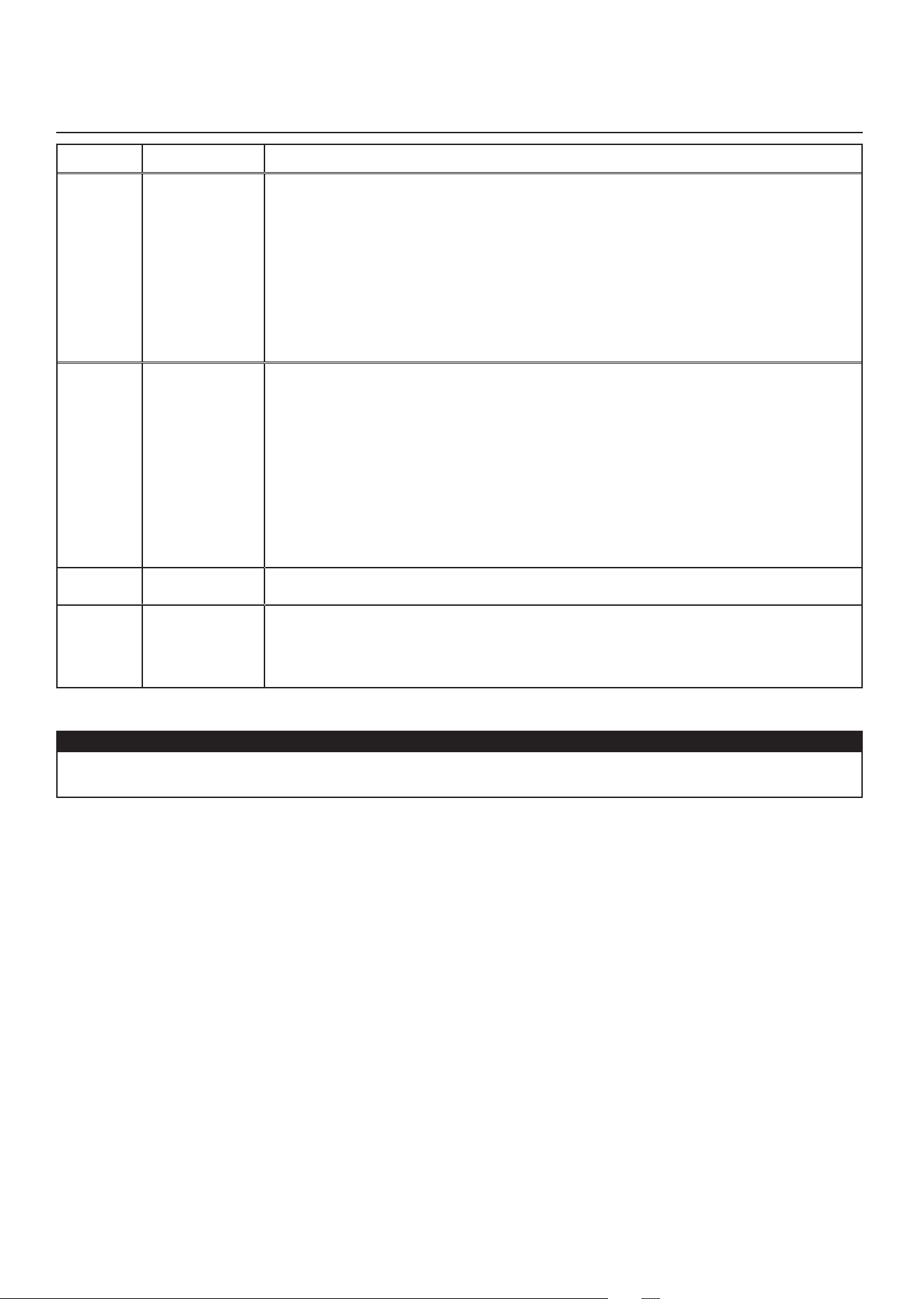
5. Remove the core.
6. Clean the condensing tray with a damp cloth.
7. Check the exterior air intake hood:
• Make sure there are no leaves, twigs, ice or snow that could be drawn into the vent.
• Clean if necessary.
8. Rotate the blower wheels by hand. If one of the wheels does not rotate easily, contact your installer.
9.Reassemblethecomponents.Payspecialattentiontothe�ltersbymakingsurethattheyareengagedintheirslots.
10. Close the unit door and reconnect power supply.
11.Reset�lters,ifrequired.Ifusinganoptionalmainwallcontrol(d
eHumidisTAT
or
A
uTomATic
), press on the INT/AUTO button for
5secondstoresetthe�lters.IfusingtheA
dvAnced
optional main wall control, follow the instructions on the touch screen.
CAUTION
Ablockedairventor�lter,evenpartially,couldcausetheunittomalfunction.Thecomfortprovidedbythe
unit could be reduced and the risk of unit frost could increase. This could cause unit breakdown and/or damage
to property.
VD0493
9.1 q
uArTerlY
WARNING
!
merv8
filTer
included
o
pTionAl
filTer
(
exHAusT
filTer
noT
included
)
e
xHAusT
filTer
included
NOTE: Theoptional�lterreplacestheMERV8�lter.
SEE DETAIL A
SEE DETAIL B
DETAIL A
DETAIL B
Pull the core 3
"
to 4
"
out.
Bendthetwo�lterframeapstoform
a 45-degree angle, as illustrated below.
Install the �lter over the core as
illustrated hereafter.
Push the core and the �lter to the
bottom of the unit.
45˚
45˚

24
1. Repeat steps 1 to 6 from the previous section and continue with the following steps:
2. Clean the recovery core:
Hrv m
odels
erv m
odels
• Remove the core.
• Let it soak in a mixture of cold or lukewarm water
and mild soap (dishwashing liquid).
• Rinse thoroughly.
• Shake the core to remove excess water and let it dry.
Remove the dust on the core using a vacuum cleaner
and a soft brush attachment.
CAUTION: DO NOT SOAK THE ENERGY RECOVERY
CORE IN WATER
3. Clean the blower assemblies. Do not disassemble the blower assemblies.
4. Remove the dust using a vacuum cleaner with a soft brush attachment.
5. Reassemble the components.
6. Reconnect power supply.
CAUTION
• Handle the recovery core with care.
p
roblem
t
ry
thiS
1. Nothing works. • See if the unit is plugged in.
• See if the unit is receiving power from the house circuit breaker or fuse.
2. Noisy unit. • Clean the unit (see Section 9). If the problem is not solved, contact your installer.
3. Condensation inside windows under
cold weather conditions.
•Operate the unit at MAX speed during activities generating excess humidity
(family gatherings, extra cooking, etc.).
• Leave curtains half-open to allow air circulation.
•Storeall�rewoodinaclosedroomwithadehumidi�erorinawellventilated
room, or store the wood outdoors.
• Keep the temperature in your house above 18 °C
(
64°F).
4. Humidity inside under hot/humid
weather conditions.
• Operate the unit in MIN speed.
• Temporarily switch to INT mode (if available).
•Useadehumidi�er.
5. Air too dry. • Operate the unit at MIN speed.
• Temporarily switch to INT mode (if available).
•Temporarilyuseahumidi�er.
6. Air too cold at the air supply register. • Make sure the outdoor hoods are not blocked.
• Operate the unit at MIN speed.
• Install a duct heater (contact your installer).
9.2 A
nnuAl
(
AT
f
All
)
10.USER’STROUBLESHOOTING
If the unit does not work properly, reset the unit by unplugging it for one minute then replug it.
Contact customer service at 1-800-567-3855 for any unresolved issue.
VD0494
9.MAINTENANCE(
Cont
’
d
)

25
11. WARRANTY
This ventilation unit is a high quality product, built and packaged with care. The manufacturer warrants to the original
purchaser of its product, that such products will be free from defects for the period stated below, from date of original
purchase.Forallunits,thewarrantycoverspartsonlyagainstanyoperationaldefect.This5-yearwarrantyissubjectto
performance of the core maintenance according to recommendations in this manual. The heat recovery core (HRV) has a
10-year warranty, and the energy recovery core (ERV) has a 5-year warranty. If any defect should occur, we urge you to
read the user guide carefully. If the problem persists, observe the following rules:
rules To follow
If the unit is defective, contact your ventilation contractor (see address on your user manual cover page). The contractor
will determine with you the reason for the defect, and if needed, do the replacement or repair. If ever it is impossible to
reach your ventilation contractor, call 1-800-567-3855 (in North America); the personnel will be pleased to give you the
phone number of a distributor or a service center near you.
replAcemenT pArTs And repAir
In order to ensure your ventilation unit remains in good working condition, you must use the manufacturer’s genuine
replacement parts only. The manufacturer’s genuine replacement parts are specially designed for each unit and are
manufacturedtocomplywithalltheapplicablecerti�cationstandardsandmaintainahighstandardofsafety.Any
third party replacement part used may cause serious damage and drastically reduce the performance level of your unit,
whichwillresultinprematurefailing.Themanufactureralsorecommendscontactingaservicedepotcerti�edbythe
manufacturer for all replacement parts and repair.
bill of purcHAse
No replacement or repair covered by the warranty will be carried out unless the unit is accompanied by a copy of the
original bill of purchase. Please retain your original.
miscellAneous cosTs
In each case, the labor costs for the removal of a defective part and/or installation of a compliant part will not be covered
by the manufacturer.
condiTions And limiTATions
Intended for a building on which Part 9 of division B from the effective version of the National Building Code of Canada
applies with additional restrictions and exception as described below.
Part 9 of Division B application according to the effective version of the National Building Code of Canada:
Part9ofDivisionBappliestoallbuildingsfallingundertheeffectiveversionoftheCanadianBuildingCodede�nitionsand
conditions as listed below:
All building* of 3 storeys or less in building height, having a building area not exceeding 600 m
2
, and usedfor major
occupanciesclassi�edasof:
Group C1, residential occupancies,
Group D2, business and personal services occupancies,
Group E3, mercantile occupancies, or
Group F, Divisions 2
4
and 3
5
, medium- and low-hazard industrial occupancies.
Andallmajoroccupanciesclassi�edasof:
Group C1, residential occupancies exceeding 600 m
2
in building area or exceeding 3 storeys in building height
However, Group F buildings are excluded since the H/ERV have only been evaluated for installation in non-hazardous
locations as per the applicable Canadian safety standard.
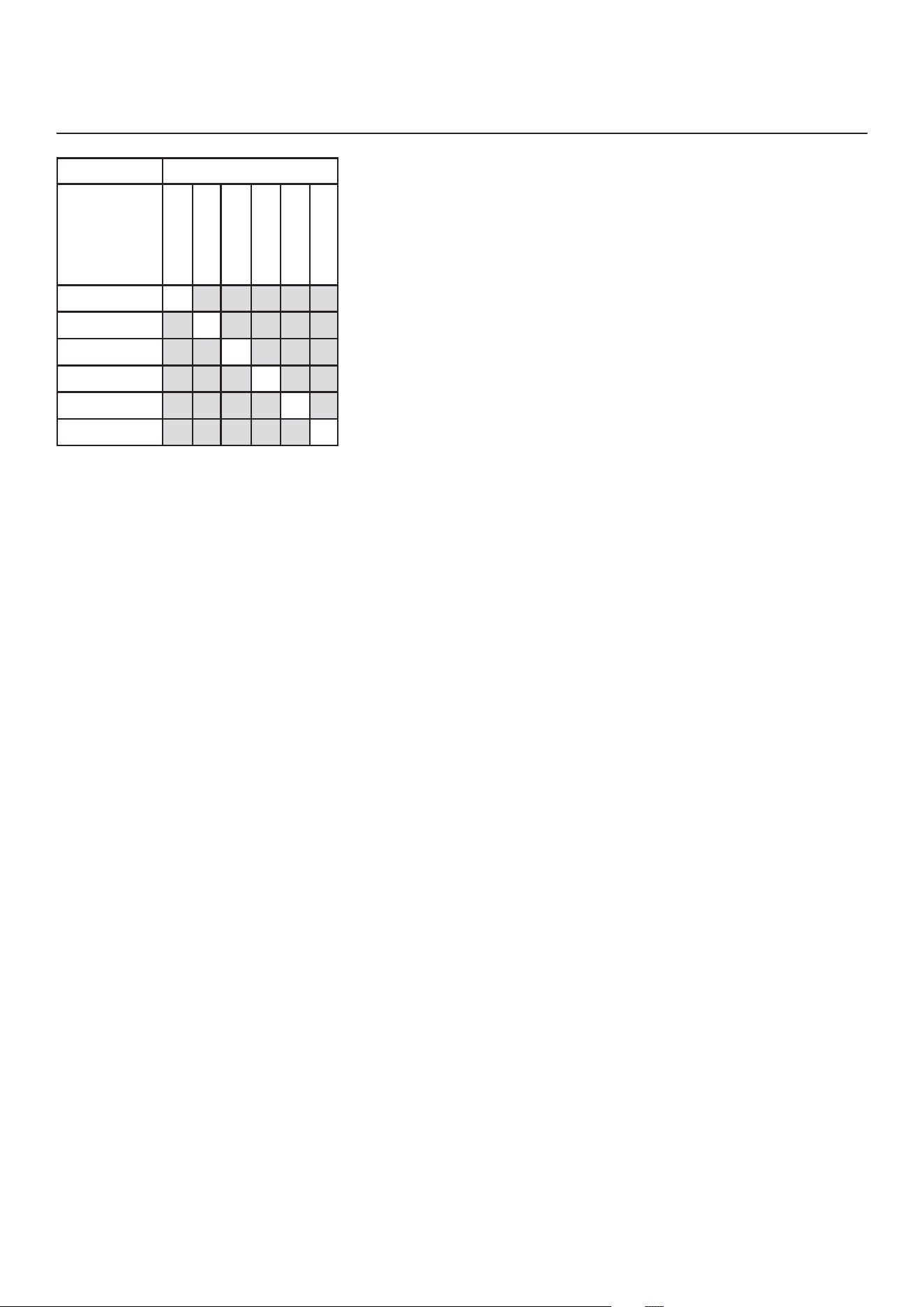
Refer to the table below for some common examples included in each building group.
Group & Division MajorOccupancy Examples
C Residential Single-family houses, Hostels,
Multi-family buildings
D Business and Personal Services Banks,Of�ces
E Mercantile Department stores, Supermarkets
Refer to note A-3.1.2.1 from the effective version of theNational Building Code of Canada for more examples.
*Building size determination consider internal separation and shall be evaluated in accordance with section 1.3.3.4 from the
effective version of the National Building Code of Canada.

26
1
Residential occupancy means the occupancy or use of a building or part thereof by persons for whom sleeping accomodation
is provided but who are not harbored for the purpose of receiving care of treatment and are not involuntarily detained.
2
Business and personal services occupancy (Group D) means the occupancy or use of a building or part thereof for the
transaction of business or the rendering or receiving of professional or personal services.
3
Mercantile occupancy (Group E) means the occupancy or use of a building or part thereof for displaying or selling of retail
goods, wares or merchandise.
4
Medium-hazard industrial occupancy (Group F, Division 2) means an industrial occupancy in which the combustible content
is more than 50 kg/m
2
or 1200 MJ/m
2
ofoorareaandnoclassi�edasahigh-hazardindustrialoccupancy.
5
Low-hazard industrial occupancy (Group F, Division 3) means an industrial occupancy in which the combustible content is
not more than 50 kg/m
2
or 1200 MJ/m
2
ofoorarea.
Exception:
Installation within a single classroom is acceptable provided the unit is installed with an independent ducting system,
distinct from the HVAC system, which is limited to that classroom and used to ventilate that classroom only. Additional
restrictions from this section remain applicable.
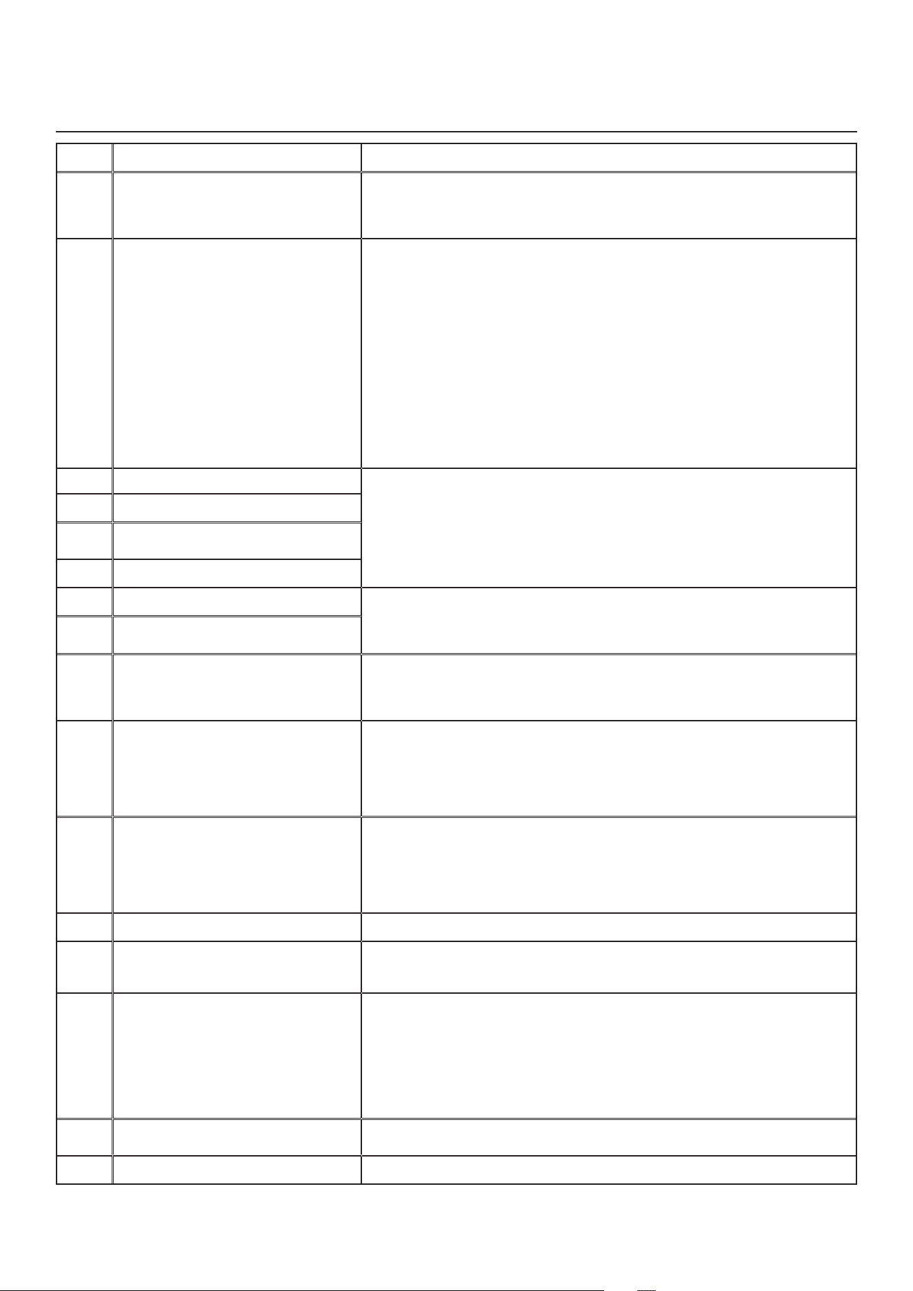
Restrictions:
The H/ERV shall not be installed within or be used to exhaust air from an environment that contains:
- Corrosive gas, vapor, emanations or solvents.
- Flammable or explosives gas, vapor, emanations, solvents or dusts.
- High concentrations of perfumes, nail polish or hair treatment products (bleaching, coloring agents, etc) such as from
hairdressing or nail salons.
- High concentration of chemical emanations from solvents, paints or other chemical cleaning agent products.
The H/ERV shall not be used to exhaust air exceeding 50% RH and 11
o
dew point over an extended period (more than 24
hours) when outdoor temperature is below -15
o
C.
The H/ERV shall not be used to exhaust air from an environment that contains high levels of particles concentration unless
theexhaustairispre-�lteredwithcaptureef�ciency�ltersselectedrelativetotheparticlesizedistributionbeforeentering
the H/ERV.
TheH/ERVshallnotbeusedtoexhaustaircookingefuentsbutcouldbeusedtoprovideventilationforakitcheninagroup
C building of 3 storeys or less in building height, having a building area not exceeding 600 m
2
only. The stale air exhaust
register location must comply with the requirement from the building code and the user manual.
Applications involving airborne pathogens or virus, smoke, harmful gas are not recommended. Such application requires
extra care to avoid recirculation and internal cross-contamination. Please contact customer service for more information.
The above warranty applies to all cases where the damage is not a result of poor installation, improper use, mistreatment or
negligence, acts of God, or any other circumstances beyond the control of the manufacturer. Furthermore, the manufacturer
willnotbeheldresponsibleforanybodilyinjuryordamagetopersonalpropertyorrealestate,whethercauseddirectlyor
indirectly by the unit. This warranty supersedes all prior warranties.
Venmar Ventilation ULC, 550 Lemire Blvd., Drummondville, Québec, Canada J2C 7W9 venmar.ca / vanee.ca 800-567-3855
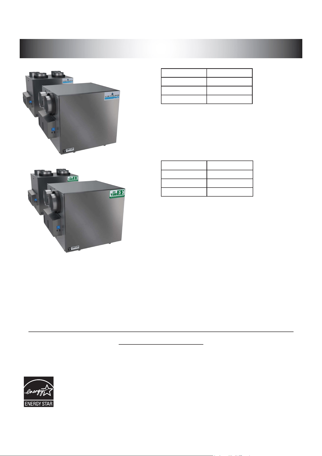
GUIDED’INSTALLATIONETD’UTILISATION
INSTALLATEUR : LIRE ET REMETTRE CES DIRECTIVES
À L’UTILISATEUR
1107074
rév
. C
VB0360
ENREGISTREZ VOTRE PRODUIT EN LIGNE AU :
venmar.ca/enregistrez-votre-produit.html ou
vanee.ca/fr/enregistrez-votre-produit.html
Pour de l’information supplémentaire, visitez venmar.ca ou vanee.ca
Venmar Ventilation ULC, 550 boul. Lemire, Drummondville, Québec, Canada J2C 7W9 venmar.ca / vanee.ca 800 567-3855
*c
es
présenTs
produiTs
sonT
HomoloGués
enerGY sTAr
®
pArce
qu
’
ils
respecTenT
des
exiGences
riGoureuses
en
mATière
d
’
efficAciTé
énerGéTique
éTAblies
pAr
r
essources
nATurelles
c
AnAdA
eT
lA
epA
des
é
TATs
-u
nis
.
i
ls
répondenT
Aux
exiGences
enerGY sTAr
seulemenT
lorsqu
’
ils
sonT
uTilisés
Au
c
AnAdA
.
A180H75rT*
A180E75RT*
A230H75RT* A230H75RS*
A210E75RT* A210E75RS*
v180H75rT*
V180E75RT*
V230H75RT* V230H75RS*
V210E75RT* V210E75RS*

2
Veuilleznoterquedansceguide,lessymbolessuivantssontutilisésa�nd’accentuercertainesinformationsparticulières:
Identi�eunedirectivequi,siellen’estpassuivie,peutcauserdegravesblessurescorporellesoulamort.
ATTENTION
Identi�eunedirectivequi,siellen’estpassuivie,peutgravementendommagerl’appareilousespièces.
NOTE:Indiqueuneinformationsupplémentairea�nderéalisercomplètementunedirective.
LIMITATION
Pour une installation et une utilisation au Canada seulement. Vise un bâtiment pour lequel la partie 9 de la division B de
la version en vigueur du Code national du bâtiment du Canada s’applique avec des restrictions et exception additionnelles
(se référer à la page 25 pour obtenir plus de détails). Les travaux d’installation et de raccordement électrique doivent être
effectuéspardupersonnelquali�é,conformémentauxcodesetauxstandardsdeconstruction,incluantceuxconcernant
la protection contre les incendies.
⚠
AVERTISSEMENT
AFIN DE DIMINUER LES RISQUES D’INCENDIE, D’ÉLECTROCUTION OU DE BLESSURES CORPORELLES, SUIVEZ LES DIRECTIVES
SUIVANTES :
1. N’utiliser cet appareil que de la façon prévue par le manufacturier.
2. Débrancher le cordon d’alimentation de l’appareil avant d’effectuer l’entretien ou la réparation.
3. Cet appareil n’est pas conçu pour fournir l’air nécessaire à la combustion et/ou à la dilution pour les appareils à
combustion.
4. Lorsquevouscoupezouperforezunmurouunplafond,nepasendommagerles�lsélectriquesouautresinstallations
qui pourraient y être dissimulés.
5. Ne pas utiliser cet appareil avec une commande de vitesse à semi-conducteur autre que celles mentionnées à la section 3.1.
6. Cetappareildoitêtremisàlaterre.Pourvotrepropreprotection,lecordond’alimentationestmunid’une�cheà3
broches.Cette�chedoitêtrebranchéeàunepriseàtroistrousavecunemiseàlaterre,conformémentaucodenational
d’électricitéainsiqu’auxcodesetrèglementslocaux.Nepasenleverlabrochepourlamiseàlaterre.Nepasutiliserde
rallonge électrique.
7. Ne pas installer dans une aire de cuisson ou brancher directement à un appareil ménager.
8. Ne pas utiliser pour évacuer des vapeurs ou des produits dangereux ou explosifs.
9. Il est recommandé de porter des lunettes et des gants de sécurité lors de l’installation, de l’entretien ou de la réparation
de ces appareils.
10. Lorsqu’une réglementation est en vigueur localement et qu’elle comporte des exigences d’installation et/ou de
certi�cationplusrestrictivesquelesprésentes,lesditesexigencesprévalentsurcellesdecedocumentetl’installateur
entend s’y conformer à ses frais.
ATTENTION
1. A�nd’éviterl’encrassementprématurédes�ltres,arrêterl’appareillorsdetravauxdeconstructionouderénovation.
2. Pourplusderenseignementsausujetdevotreappareil,veuillezlirelesautocollantsapposéssurcelui-ci.
3. S’assurer que les bouches appropriées donnent à l’extérieur. Ne pas aspirer/évacuer l’air dans des espaces restreints
comme l’intérieur des murs ou plafond ou dans le grenier, un vide sanitaire ou un garage. Ne pas essayer de récupérer
l’airévacuéprovenantd’unesécheuseoud’unehottedecuisinière.
4. Ne pas installer de conduits directement au-dessus ou à moins de 2 pi (0,61 m) d’une fournaise, de son conduit de
distribution,d’unechaudièreoud’unappareildechauffage.Siunconduitdoitêtreraccordéauplenumderetourd’air
de la fournaise, il doit être installé à au moins 10 pi (3,1 m) du raccordement de ce plenum à la fournaise.
5. Le réseau de conduits doit être installé selon tous les codes locaux et nationaux en vigueur.
6. En cas d’absence prolongée (plus de deux semaines), laissez une personne responsable véri�er régulièrementque
l’appareil fonctionne adéquatement.
7. Si le réseau de conduits traverse un espace non tempéré (ex. : grenier), l’appareil doit fonctionner continuellement sauf
lorsdesonentretienoudesaréparation.Latempératureambiantedelamaisonnedoitégalementjamaissesituer
sous 18 °C (65 °F).
8. Au moins une fois par année, les composantes électroniques et mécaniques de cet appareil devraient être inspectées
pardupersonnelquali�é.
9. Ne pas utiliser votre appareil lorsque des travaux de construction ou de rénovation sont en cours, ou lors du sablage de
jointsdecloisonsèche.Certainstypesdepoussièreetdevapeurspeuventendommagervotresystèmedeventilation.
10. Pendant l’hiver, s’assurer que les bouches extérieures ne sont pas encombrées par la neige. Il est également important
de s’assurer que l’appareil n’aspire pas de neige pendant les tempêtes de neige. Au besoin, arrêter l’appareil pendant
quelques heures.
11. Le contrôle électronique de cet appareil contient un microprocesseur qui peut ne pas fonctionner normalement en raison
d’interférences ou à la suite de courtes interruptions de courant. Si cela se produit, débrancher l’appareil, attendre une
dizaine de secondes, puis rebrancher l’appareil.
12. Ne pas faire un usage abusif de diffuseurs d’odeur ou de produits chimiques puisque certains peuvent endommager le
matériau des composantes de l’appareil.
⚠
AVERTISSEMENT

3
TABLE DES MATIÈRES
1. DONNÉES TECHNIQUES ....................................................................................................4
1.1 DISTRIBUTION DE L’AIR (FONCTIONNEMENT NORMAL) ........................................................................4
2. INSTALLATION ....................................................................................................................4
2.1 EMPLACEMENT ET INSTALLATION DE L’APPAREIL .................................................................................4
2.2 INSTALLATION DES CONDUITS ET GRILLES ...........................................................................................6
2.2.1 S
YSTÈME
INDÉPENDANT
(T-1) (L
E
MODE
RECIRCULATION
PEUT
FONCTIONNER
AVEC
CETTE
CONFIGURATION
.) ................6
2.2.2 S
YSTÈME
D
’
ÉVACUATION
À
LA
SOURCE
(T-2) (L
E
MODE
RECIRCULATION
PEUT
FONCTIONNER
AVEC
CETTE
CONFIGURATION
.)6
2.2.3 I
NSTALLATION
SIMPLIFIÉE
(T-4) (L
E
MODE
RECIRCULATION
NE
PEUT
PAS
FONCTIONNER
AVEC
CETTE
CONFIGURATION
.) ....7
2.3 RACCORDER LE BOYAU DE DRAINAGE (VRC SEULEMENT).................................................................8
ATTACHE AUTOBLOQUANTE ...........................................................................................................................8
ATTACHE AUTOBLOQUANTE ...........................................................................................................................8
2.4 INSTALLER LES BOUCHES EXTÉRIEURES .............................................................................................9
2.5 RACCORDER LES CONDUITS À L’APPAREIL ............................................................................................9
2.5.1 R
ACCORDEMENT
DES
CONDUITS
................................................................................................................... 10
3. BRANCHEMENT ...............................................................................................................11
3.1 BRANCHEMENT DE LA COMMANDE MURALE PRINCIPALE OPTIONNELLE ...................................... 11
3.1.1 B
RANCHEMENT
DE
LA
COMMANDE
MURALE
PRINCIPALE
OPTIONNELLE
D
ÉSHUMIDISTAT
OU
A
UTOMATIQUE
..................... 11
3.1.2 B
RANCHEMENT
DE
LA
COMMANDE
MURALE
PRINCIPALE
OPTIONNELLE
A
VANCÉE
À
ÉCRAN
TACTILE
.............................. 11
3.2 BRANCHEMENT DE LA COMMANDE MURALE AUXILIAIRE OPTIONNELLE .......................................12
3.2.1 B
RANCHEMENT
DE
LA
COMMANDE
MURALE
AUXILIAIRE
OPTIONNELLE
20-40-60 ....................................................12
3.2.2 B
RANCHEMENT
DE
LA
COMMANDE
MURALE
AUXILIAIRE
OPTIONNELLE
DE
TYPE
CONTACT
SEC
(
EX
.
MINUTERIE
MÉCANIQUE
) 12
3.3 RACCORDEMENT ÉLECTRIQUE AU SYSTÈME CENTRAL À AIR PULSÉ .............................................13
3.3.1 F
ONCTIONNEMENT
DE
L
’
APPAREIL
AVEC
CONNEXION
À
CONTACT
SEC
...................................................................13
3.3.2 I
NTERCONNEXION
DE
L
’
APPAREIL
AVEC
UN
SYSTÈME
CENTRAL
À
AIR
PULSÉ
(R/C/G/G
F
) .........................................13
3.3.3 S
YNCHRONISATION
AVEC
LE
FONCTIONNEMENT
DU
SYSTÈME
CENTRAL
À
AIR
PULSÉ
.................................................13
4. SCHÉMA ÉLECTRIQUE ....................................................................................................14
5. NAVIGATION À L’ÉCRAN ACL ..........................................................................................15
5.1 ÉCRAN ACL ...............................................................................................................................................16
5.2 PREMIER DÉMARRAGE DE L’APPAREIL .................................................................................................16
5.3 MODIFICATION DES RÉGLAGES .............................................................................................................16
5.3.1 P
ROCÉDURE
POUR
MODIFIER
LE
RÉGLAGE
MIN
PI
³/
MIN
......................................................................................16
5.3.2 P
ROCÉDURE
POUR
MODIFIER
LE
RÉGLAGE
MAX
PI
³/
MIN
.....................................................................................16
5.3.3 P
ROCÉDURE
POUR
MODIFIER
LE
RÉGLAGE
DES
OPTIONS
...................................................................................16
5.3.4 P
ROCÉDURE
POUR
MODIFIER
LE
RÉGLAGE
DES
DÉBITS
D
’
AIR
INDÉPENDANTS
.........................................................16
5.4 RÉINITIALISATION DES RÉGLAGES .......................................................................................................17
6. UTILISER VOTRE APPAREIL ............................................................................................17
6.1 VOTRE SYSTÈME DE VENTILATION ........................................................................................................17
6.2 COMMANDE INTÉGRÉE ...........................................................................................................................17
6.3 AFFICHAGE DU MODE AHU .....................................................................................................................17
7. PIÈCES DE REMPLACEMENT ..........................................................................................18
8. DÉPANNAGE POUR INSTALLATEUR ..............................................................................20
8.1 PROTECTION ÉLECTRONIQUE POUR ÉVITER UNE PRESSION STATIQUE ANORMALEMENT ÉLEVÉE22
9. ENTRETIEN .......................................................................................................................23
9.1 TRIMESTRIEL ............................................................................................................................................23
9.2 ANNUEL (À L’AUTOMNE) ...........................................................................................................................24
10. DÉPANNAGE POUR L’UTILISATEUR .............................................................................24
11. GARANTIE ........................................................................................................................25
4
1. DONNÉES TECHNIQUES
NOTE: Lestableauxdeperformance,lesdimensionsetlesspéci�cationssontinscritssurles�chestechniquesdes
appareils.
Visitez note site Web au venmar.ca ou vanee.ca.
1.1 d
isTribuTion
de
l
’
Air
(f
oncTionnemenT
normAl
)
2. INSTALLATION
Le port de lunettes et de gants de sécurité est recommandé lors de l’installation, de l’entretien ou du nettoyage
del’appareila�nderéduirelerisquedeblessurequipourraitêtrecauséeparlaprésencedemétalminceet/
oudepiècesmobilesenhauteur.
AVERTISSEMENT
!
2.1 e
mplAcemenT
eT
insTAllATion
de
l
’
AppAreil
VF0077
Aspiration
d’air vicié
Aspiration
d’air frais
Distribution
d’air frais
Évacuation
d’air vicié
Aspiration
d’air vicié
Aspiration
d’air frais
Distribution
d’air frais
Évacuation
d’air vicié
Choisir un emplacement adéquat pour l’appareil :
• Dans un endroit chauffé de la maison où la température est maintenue entre 10 °C/50 °F et 65 °C/149 °F;
• Autant que possible, éloigné des endroits les plus fréquentés (salle à manger, salon, chambres à coucher);
• De façon à pouvoir accéder facilement à l’intérieur du boîtier pour l’entretien trimestriel et annuel, ainsi qu’au compartiment
électrique sur le côté de l’appareil;
• Prèsd’unmurextérieur,defaçonàréduirelalongueurdesconduitsexiblesisolés;
• Appareils HRV : à proximité d’un drain. S’il n’y en a pas, se servir d’un seau pour récupérer l’écoulement;
• Éloigné des cheminées chaudes, du panneau des circuits électriques et autres risques d’incendie;
• Prévoir une source d’alimentation électrique standard à moins de 6 pi.
Renseignementspourlesconsommateurs
A.A�nd’assurerlefonctionnementsilencieuxdesVRC/VREcerti�ésENERGYSTAR,chaquemodèledeproduitdoitêtre
installé avec les techniques d’atténuation du son appropriées.
B.LamanièredontonainstallévotreVRC/VREpeutfaireunedifférenceconsidérablequantàl’énergieélectriqueque
vousutilisez.A�nderéduirelaconsommationd’électricitéduVRC/VRE,onrecommandeuneinstallationautonome
entièrementcanalisée.Sivouschoisissezuneinstallationsimpli�éequiactionnel’appareildetraitementd’airdevotre
générateurd’airchaudaux�nsd’uneventilationdepièceenpièce,ungénérateurd’airchaudquiconsommepeu
d’électricité et qui est muni d’un moteur de ventilation à vitesse variable et à commutation électronique vous permettra
de réduire votre consommation d’énergie électrique ainsi que vos coûts d’exploitation.
C.L’installationd’unecommandeaccessibleauxutilisateurssurlemodèledeproduitamélioreleconfortetpourrait
considérablement réduire la consommation d’énergie du produit.
ATTENTION
S’assurer qu’aucun morceau de laine minérale n’entre dans l’appareil durant l’installation. Sinon, cela pourrait
réduire le débit et générer des vibrations et du bruit dans l’appareil.
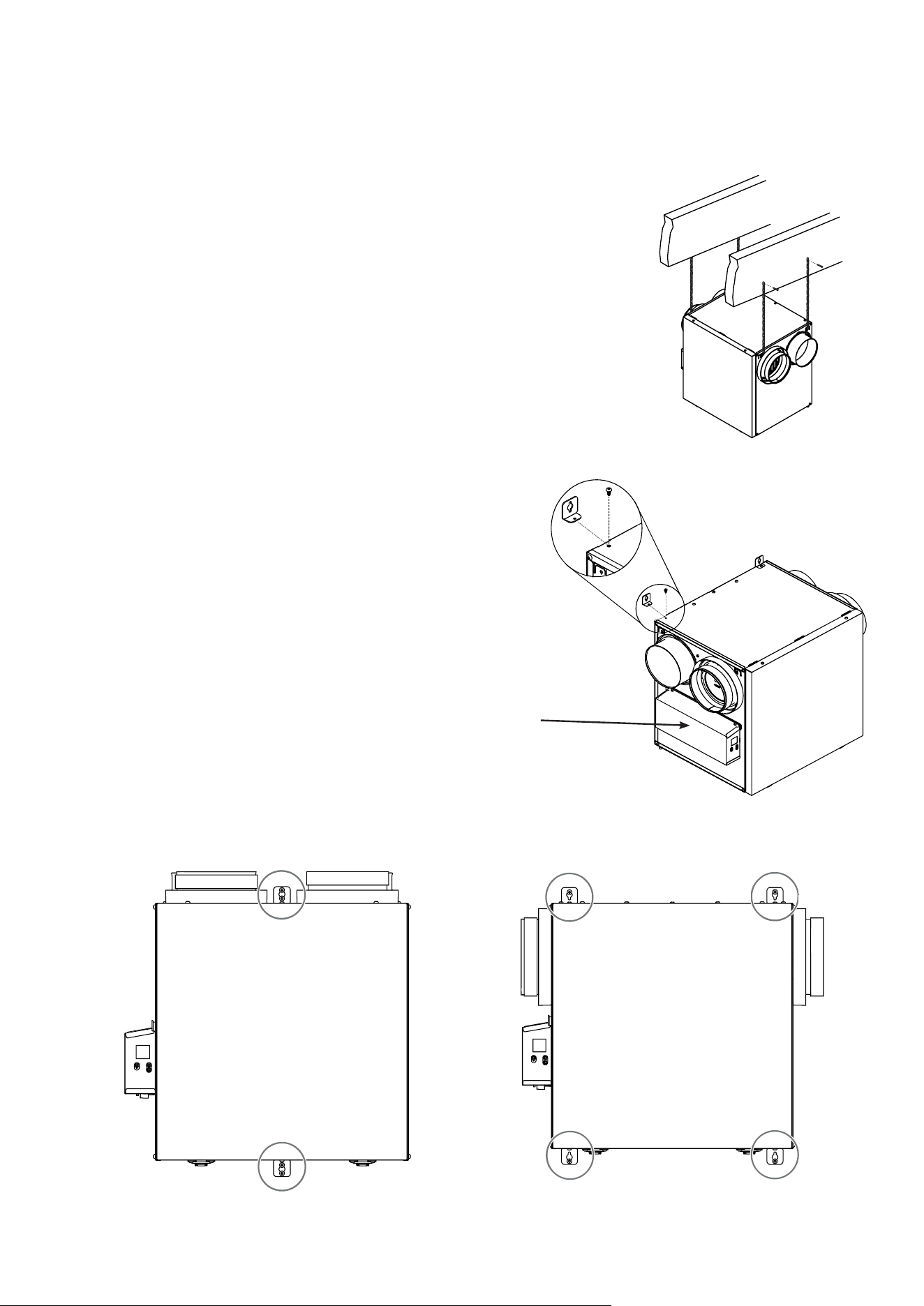
5
Suspendu aux solives :
• Plierlégèrementlessupportssurl’appareila�nd’yinsérerleschaînesincluses.
• Suspendre l’appareil aux solives à l’aide des chaînes incluses. Les ressorts ne
sont pas nécessaires.
• S’assurer que l’appareil est de niveau. Le dénivellé ne doit pas dépasser 1/4 po.
OU
Installé au mur :
• Choisir l’/les emplacement(s) approprié(s) pour les supports (voir
l’illustration ci-dessous) selon la position du/des montant(s).
• Insérer les supports fournis sous le châssis de l’appareil (voir
l’illustration ci-contre).
• À l’aide de la vis n
o
8 x 3/8 po, installer le support.
• À l’aide de 4 vis n
o
8 x 1 1/2 po, installer l’appareil au mur en
s’assurant que toutes les vis mordent dans le montant.
• S’assurer que l’appareil est de niveau. Le dénivellé ne doit pas dépasser
1/4 po.
2.1 e
mplAcemenT
eT
insTAllATion
de
l
’
AppAreil
(
suiTe
)
VD0485
VD0488
VD0487
INSTALLATION AVEC 2 SUPPORTS INSTALLATION AVEC 4 SUPPORTS
VD0486
NOTE : Garder un dégagement
de 3 po sur le côté du
boîtier électrique pour
le refroidissement et
l’entretien.
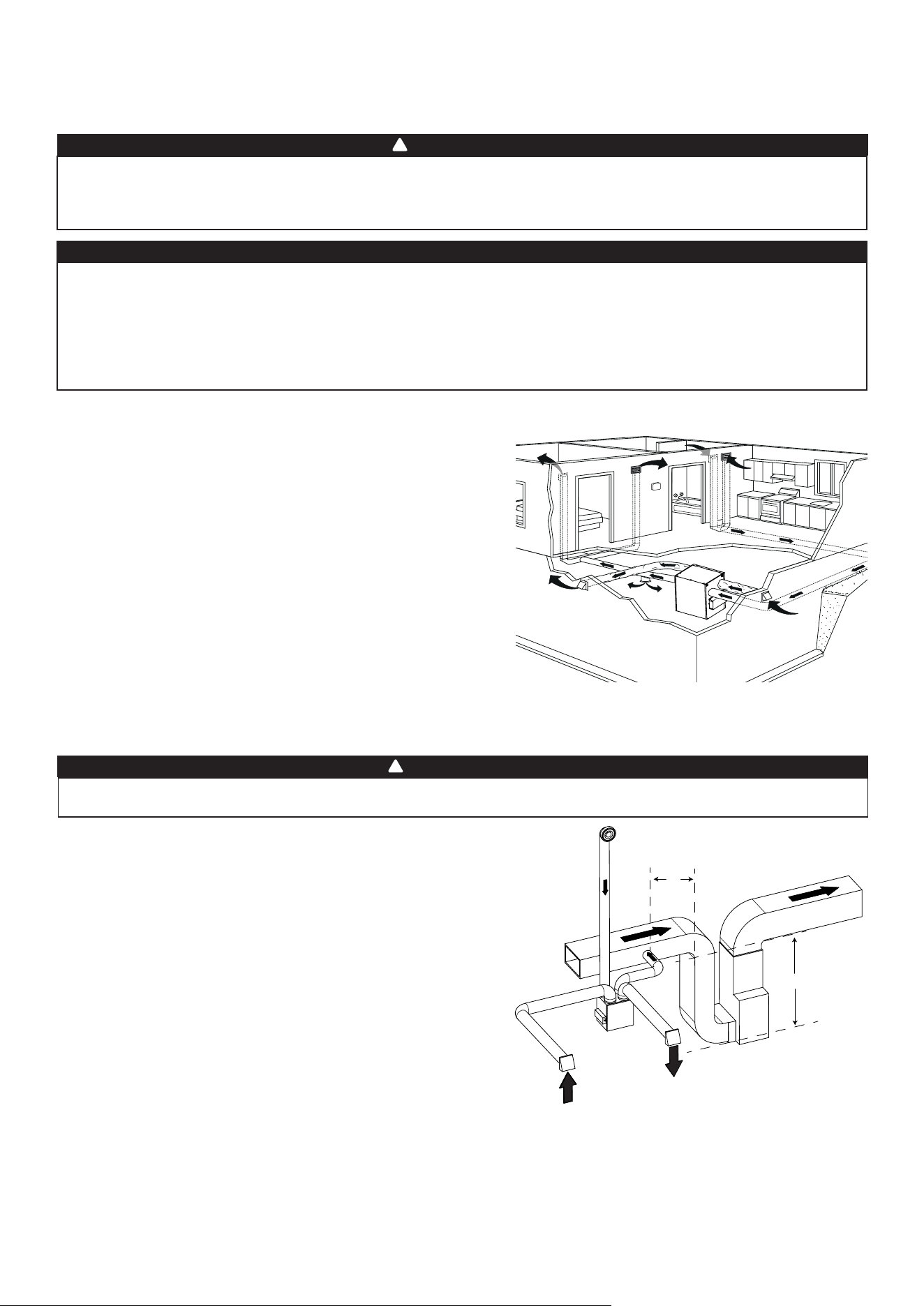
6
VH0165
A
B
a
Spiration
d
’
air
viCié
:
• Installer les grilles dans les pièces qui génèrent des polluants :
Cuisine, salle de bains, buanderie, etc.
• Installer les grilles sur un mur intérieur, à une distance de 6 po à
12 po (152 mm à 305 mm) du plafond OU les installer au plafond.
• Installer la grille de cuisine à au moins 4 pieds (1,2 m) du four.
• Si requis, des ventilateurs de salle de bains et une hotte de
cuisinièrepeuventêtreutiliséspourmieuxévacuerl’airvicié.
• Pour les maisons ayant plus d’un étage, il faut prévoir au moins
une grille d’aspiration au niveau le plus élevé.
d
iStribution
d
’
air
fraiS
:
• Installer dans les chambres à coucher, salle à manger, salle de
séjouretsous-sol.
• Installer les grilles soit au plafond ou en haut des murs, en
dirigeantleuxd’airversleplafond.
• Si une grille doit être installée au plancher, diriger l’air vers un mur.
2.2.1 s
YsTème
indépendAnT
(T-1) (l
e
mode
recirculATion
peuT
foncTionner
Avec
ceTTe
confiGurATion
.)
2.2 i
nsTAllATion
des
conduiTs
eT
Grilles
Nejamaisinstallerunegrilled’évacuationd’airviciédansunepièceoùsetrouveunappareildecombustion
comme une fournaise, un chauffe-eau à gaz, un foyer ou tout autre appareil ou équipement pouvant générer
desgazcontaminantsoudespolluants.Unepressionnégativepourraitainsiêtrecrééedanslapièceetnuire
à l’évacuation des gaz ou polluants, ce qui peut avoir de graves conséquences sur la santé.
AVERTISSEMENT
!
a
Spiration
d
’
air
viCié
:
Commepourlesystèmeindépendant,décritàlasection2.2.1.
d
iStribution
d
’
air
fraiS
:
• Relier la bouche de distribution d’air frais de l’appareil au
conduitderetourdusystèmecentralàairpulsé,àaumoins10
pieds de celui-ci (A+B)*.
* Cette distance de 10 pieds s’applique seulement dans les régions
où la température extérieure descend sous le point de congélation
0°C (32°F).
NOTE : Il est recommandé, sans toutefois être essentiel, que le
ventilateurdu systèmecentralàair pulsé soitsynchronisé
avec l’appareil (voir la section 3.3).
2.2.2 s
YsTème
d
’
évAcuATion
à
lA
source
(T-2) (l
e
mode
recirculATion
peuT
foncTionner
Avec
ceTTe
confiGurATion
.)
Leraccordementdesconduitsausystèmecentralàairpulsépeutêtreréglementéparcertainscodesetnormes.
Ilestdevotreresponsabilitédeconsulteretd’appliquerlesexigenceslocalesa�nd’évitertoutenon-conformité.
AVERTISSEMENT
!
NOTE:Pourcetypedecon�guration,l’optionT-1doitêtresélectionnéeàl’écranACLlorsdel’auto-balancementdel’appareil.
NOTE:Pourcetypedecon�guration,l’optionT-2doitêtre
sélectionnéeàl’écranACLlorsdel’auto-balancementdel’appareil.
A+b=
min
10
pi
Aspiration
d’air vicié de la
salle de bain
Distribution d’air
frais
Évacuation
d’air vicié
Aspiration d’air
frais
Silesconduitsdoiventpasserparunespacenontempéré(ex.:grenier),toujoursutiliserdesconduitsisolés
pour éviter que de la condensation se forme à l’intérieur ou à l’extérieur du conduit, ce qui pourrait causer
des dégâts matériels et/ou la prolifération de moisissure. De plus, si le conduit de distribution d’air frais et/
ou le conduit d’aspiration d’air vicié passe(nt) par un espace non tempéré, l’appareil doit être réglé pour
fonctionner de façon continue par temps froid (sous 10°C/50°F). Un mouvement d’air continu à l’intérieur
desconduitséviteralaformationdecondensation.L’appareilpeutêtrearrêtétemporairementàdes�ns
d’entretien et/ou de réparation dans de telles conditions.
ATTENTION
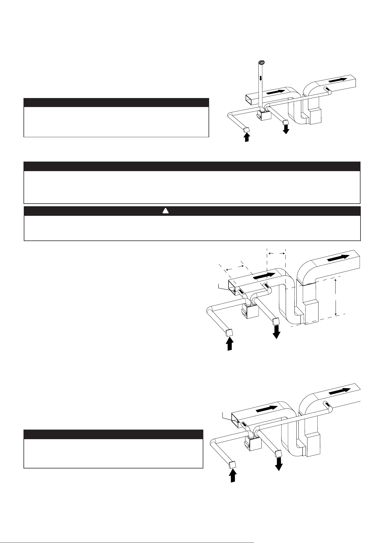
7
2.2.3 i
nsTAllATion
simplifiée
(T-4) (l
e
mode
recirculATion
ne
peuT
pAs
foncTionner
Avec
ceTTe
confiGurATion
.)
Lesystèmecentralàairpulsédoitêtresynchroniséavecl’appareilpuisquel’évacuationetladistributiond’air
fraisproviennentdelamêmesection.Lesystèmecentralàairpulsédoitfonctionnerpouréviterquel’airfrais
soit directement aspiré par l’évacuation; ce qui réduirait considérablement l’apport d’air frais au bâtiment. Voir la
section 3.3 pour le raccordement.
ATTENTION
Le raccordement des conduits au système central à air pulsé peut être réglementé par certains codes et
standards.Ilestdevotreresponsabilitédeconsulteretd’appliquerlesexigenceslocalesa�nd’évitertoute
non-conformité.
AVERTISSEMENT
!
VH0168
L’airfraisetviciéempruntelesconduitsdusystèmecentralàair
pulsé,cequisimpli�el’installation.
L’utilisation d’un ventilateur de salle de bains et d’une hotte de
cuisinièreestrecommandépourmieuxévacuerl’airvicié.
a
Spiration
d
’
air
viCié
:
Relier la bouche d’aspiration d’air vicié de l’appareil au conduit de
retourdusystèmecentralàairpulsé,aumoins 3 pieds (0,9 m) en
amont de la bouche de distribution d’air frais de l’appareil.
d
iStribution
d
’
air
fraiS
:
Relier la bouche de distribution d’air frais de l’appareil au
conduitderetourdusystèmecentralàairpulsé,àaumoins
10 pieds de celui-ci (A+B)*.
* Cette distance de 10 pieds s’applique seulement dans les
régions où la température extérieure descend sous le point de
congélation 0°C (32°F).
VH0167
C
B
A
A+b=
min
10
pi
c=3
pi
Distribution
d’air frais
Aspiration
d’air vicié
Évacuation
d’air vicié
Aspiration d’air
frais
Évacuation
d’air vicié
Aspiration d’air
frais
Distribution
d’air frais
Aspiration
d’air vicié
NOTE:Pourcetypedecon�guration,l’optionT-4doitêtre
sélectionnéeàl’écranACLlorsdel’auto-balancementdel’appareil.
i
nsTAllATion
AlTernATive
(T-5)
(
l
e
mode
recirculATion
ne
peuT
pAs
foncTionner
Avec
ceTTe
confiGurATion
.)
L’appareildoitêtresynchroniséaveclefonctionnementdusystème
central à air pulsé pour éviter la formation de condensation et
la croissance de moisissures dans les conduits de distribution du
systèmecentralàairpulsési lemodeclimatisationdusystème
central à air pulsé est utilisé.
Cette con�guration n’est pas recommandée avec un
systèmecentralàairpulséàhautevélocité.Lespressions
élevées généréespar ces systèmespourraient altérerle
bon fonctionnement de l’appareil et générer des erreurs.
ATTENTION
NOTE:Pourcetypedecon�guration,l’optionT-5doitêtre
sélectionnéeàl’écranACLlorsdel’auto-balancementdel’appareil.
VH0166
i
nsTAllATion
AlTernATive
(T-3) (l
e
mode
recirculATion
peuT
foncTionner
Avec
ceTTe
confiGurATion
.)
L’appareildoitêtresynchroniséaveclefonctionnementdusystème
central à air pulsé pour éviter la formation de condensation et
la croissance de moisissures dans les conduits de distribution du
système central à air pulsé si le mode climatisation du système
central à air pulsé est utilisé.
Cettecon�gurationn’estpasrecommandéeavecunsystème
central à air pulsé à haute vélocité. Les pressions élevées
générées par ces systèmes pourraient altérer le bon
fonctionnement de l’appareil et générer des erreurs.
ATTENTION
NOTE:Pourcetypedecon�guration,l’optionT-3doitêtre
sélectionnéeàl’écranACLlorsdel’auto-balancementdel’appareil.
Aspiration
d’air vicié de la
salle de bain
Distribution
d’air frais
Évacuation
d’air vicié
Aspiration d’air
frais
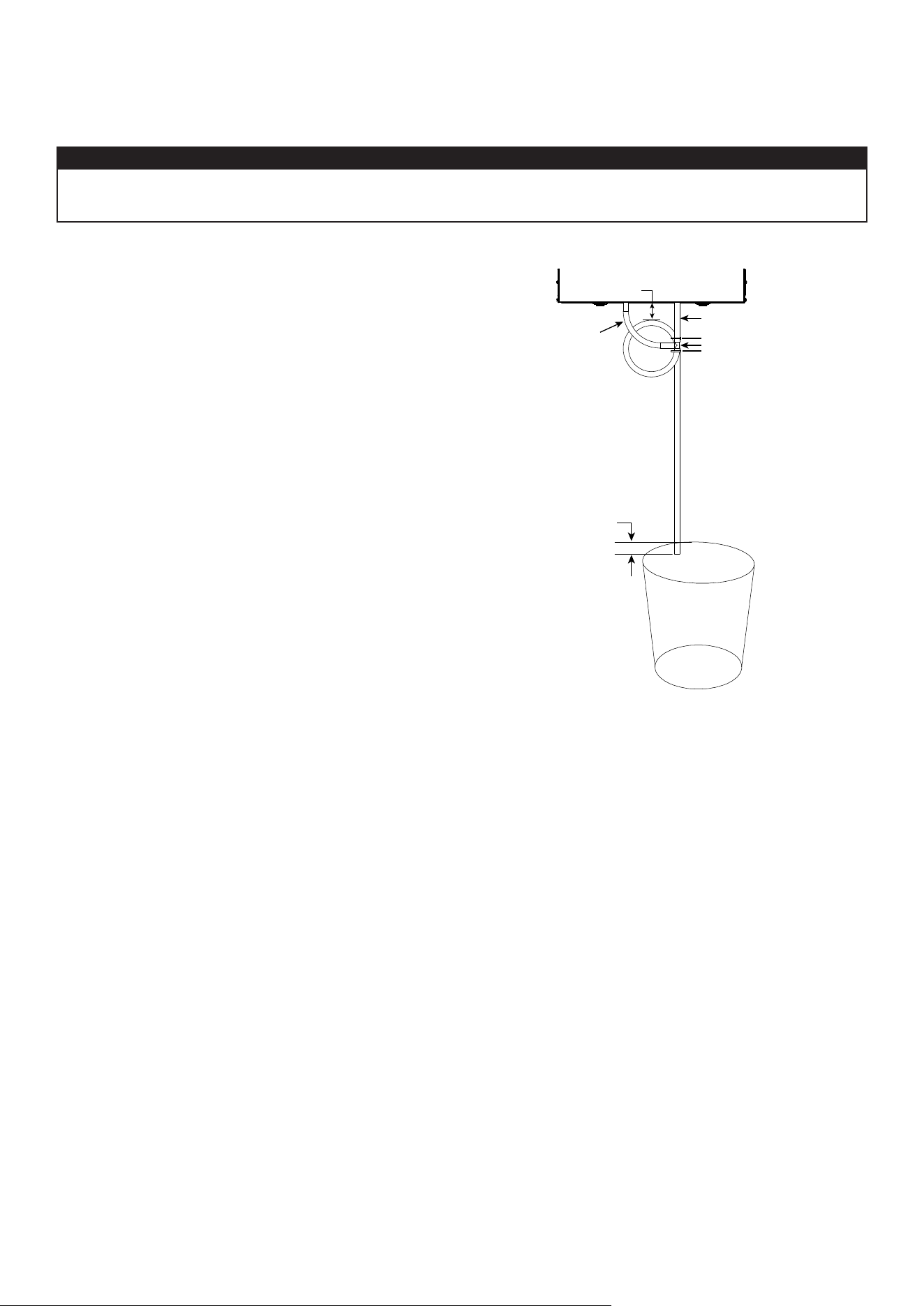
8
2.3 r
Accorder
le
boYAu
de
drAinAGe
(
vrc
seulemenT
)
Installerleboyaudedrainageinclusetl’acheminerversundrainouunechaudière.Cetappareilpeutgénérer
une bonne quantité d’eau par temps plus frais; il est nécessaire d’installer le boyau de drainage adéquatement
a�nd’évitertoutdégâtet/oubrismatériel.
ATTENTION
• Couper la longueur appropriée de boyau de drainage
(voir l’illustration à droite).
• Raccorder le boyau à l’adaptateur fourni.
• Faire une boucle dans le boyau pour retenir l’eau a�n
d’empêcher que l’appareil n’aspire de mauvaises odeurs.
• Ajouterdel’eaudanslabouclepourprévenirlebruitou
lessifements.
• S’assurer qu’il y a une distance d’au moins 2 po entre
l’appareil et la boucle du boyau (voir l’illustration à droite).
• À l’aide des attaches autobloquantes fournies, attacher le
boyau tel qu’illustré.
• Raccorder le boyau au drain du sous-sol ou à un seau.
• IMPORTANT: Si un seau est utilisé pour recueillir l’eau,
placer le bout du boyau à environ 1 po du bord du seau
a�nd’éviterquel’eauneremontedansl’appareil.
≥
2"(51 mm)
±
1"(25 mm)
5 1/4" (133 mm)
9 3/4" (248 mm)
T
VO0296
Attache autobloquante
Attache autobloquante
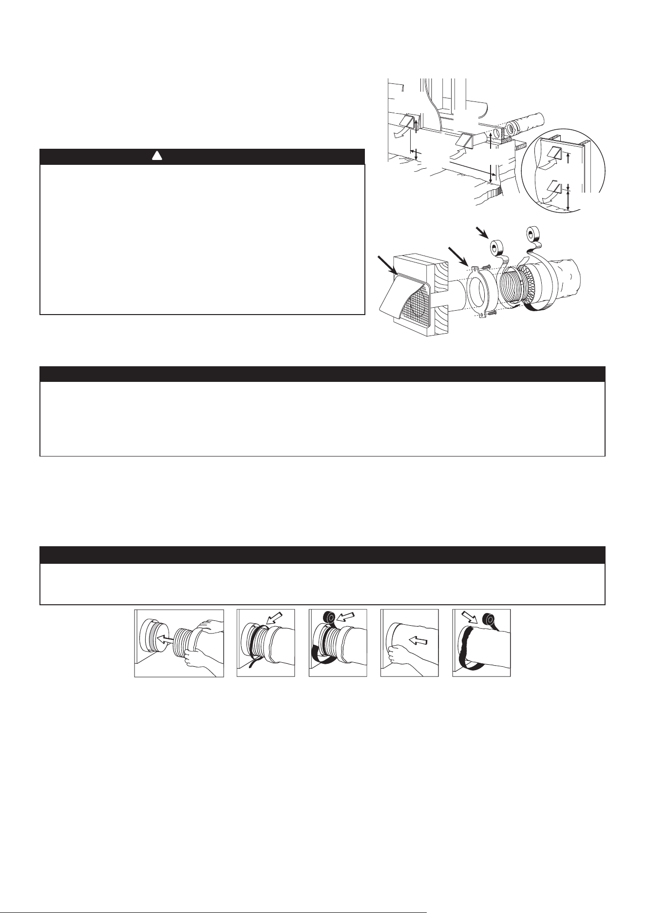
9
2.4 i
nsTAller
les
boucHes
exTérieures
Pour éviter toute contamination :
• Garder une distance d’au moins 6 pieds (1,8 m) entre les deux
bouches.
• Installer la/les bouche(s) à au moins 18 pouces (457 mm) du sol OU à la hauteur
prévuedel’accumulationdeneigesicettedernièreestplusimportante.
Consulter l’illustration ci-contre pour relier le conduit isolé aux bouches extérieures.
Un capuchon anti-rafales devrait être installé sur la bouche d’aspiration d’air frais
dans les régions où il tombe généralement beaucoup de neige.
VD0028
18
po
(457
mm
)
18
po
(457
mm
)
6
pi
(1,8
m
)
6
pi
(1,8
m
)
18
po
(457
mm
)
e
mplaCement
alternatif
C
alfeutre
S
ortie
d
’
air
viCié
*
e
ntrée
d
’
air
fraiS
C
ollier
de
Serrage
et
ruban
adhéSif
en
toile
S’assurer que la bouche d’entrée d’air se trouve à au moins 6 pi
(1,8 m) des éléments suivants :
•Sortiedesécheuse,desystèmecentralàairpulséàvitesse
variable, d’aspirateur central;
• Sortie de compteur de gaz, barbecue à gaz;
• Sortie de toute source de combustion;
• Poubelle et toute autre source de contamination.
Ignorer ces recommandations pourrait grandement détériorer
la qualité de l’air entrant dans la maison ce qui, dans certains
cas, pourrait avoir des répercussions sur la santé.
Encasdeconitentrenosconditionsetlesexigenceslocales,
cesdernièresontpriorité.
AVERTISSEMENT
!
T
rAnsiTion
vers
des
conduiTs
de
8
po
Si des conduits de 8 po sont utilisés, installer des transitions de 6 po à 8 po sur les bouches de l’appareil. Utiliser
seulementdurubanàconduitspour�xerlestransitionsauxbouchesdel’appareil.Sidesconduitsrigidessontutilisés,les
raccorderàlatransitionaumoyend’unesectionde12podeconduitexible(voirci-dessus).
c
onduiTs
riGides
Pourprévenirlesfuitesd’eaudansl’isolantdesconduitsrigidesisolésducôtéfroid,scellertouslesjointsdeceux-ciavecdu
ruban à conduits.
Pouréviterlatransmissiondevibrations,toujoursraccorderlesconduitsrigidesàl’appareilaumoyend’unesectionde12po
deconduitexible.Pourraccorderlesconduitsrigidesisolésàl’appareil(côtéfroid)àl’aidedeconduitexibleisolé,suivrela
procédureàlasection2.4.Pourraccorderlesconduitsrigidesnonisolésàl’appareil(côtéchaud)àl’aidedeconduitexible
non isolé, utiliser une attache autobloquante.
2.5 r
Accorder
les
conduiTs
à
l
’
AppAreil
c
onduiTs
flexibles
isolés
Procédercomme suitpourlebranchementdu conduitexibleisoléauxbouchesdel’appareil(évacuationd’airviciéet
aspiration d’air frais de l’extérieur).
1. Tirersurl’isolantpourexposerleconduitexibleetleplacer par-dessusl’anneau intérieur de la bouche.
2. Àl’aided’uneattacheautobloquante,�xerleconduitexibleintérieuràlabouche.
3. Scellerlejointàl’aidederubanàconduit.
4. Tirerl’isolantetlecoupe-vapeurpar-dessuslejoint,les insérer entre les anneaux intérieur et extérieur de la bouche et
les�xeràl’aidederubanàconduit.
• Siles conduitsdoiventpasserparun espacenontempéré(ex.:grenier),toujoursutiliserdesconduits
isolés pour éviter que de la condensation se forme à l’intérieur ou à l’extérieur du conduit, ce qui pourrait
causer des dégâts matériels et/ou la prolifération de moisissure.
• Nejamaisutiliserdevispourraccorderlesconduitsauxbouchesa�ndenepasnuireau
fonctionnement des volets situés à l’intérieur des bouches. Un volet non fonctionnel pourrait faire geler
l’appareil, ce qui pourrait occasionner des bris.
ATTENTION
• Le pare-vapeur doit demeurer intact et exempt de �ssures ou d’ouvertures. Une ouverture pourrait
générer de la condensation à l’intérieur ou à l’extérieur du conduit, ce qui pourrait occasionner des dégâts
matériels et/ou la prolifération de moisissure à long terme.
ATTENTION
NOTE:Ilestrecommandéd’utiliserdesconduitsde8poaulieudesconduitsde6posiledébitd’airrequisestsupérieur
à200pi
3
/minetsiunlongtrajetdeconduitouunegrandequantitédecoudesestutilisé.Cecipermettrad’éviterd’avoir
unepressionstatiquetropélevéedanslesconduits.
C
alfeutre
*Ne pas installer de bouche de sortie
d’air vicié avec volet anti-retour puisqu’il
pourrait geler en hiver.
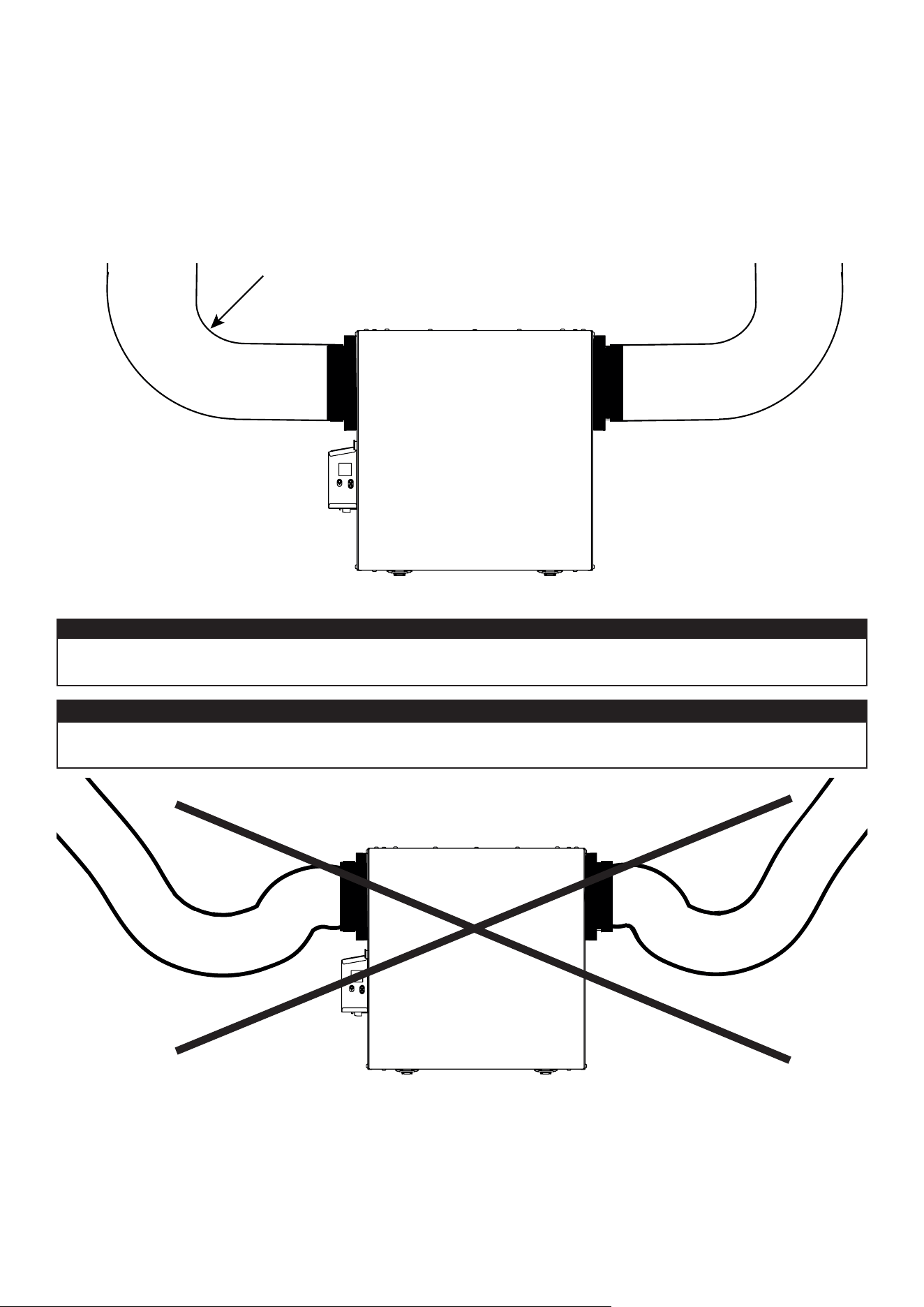
10
2.5.1 r
AccordemenT
des
conduiTs
VD0489
i
nStallation
CorreCte
VD0490
i
nStallation
inCorreCte
IMPORTANT: S’assurer de raccorder les conduits tel qu’illustré ci-dessous pour obtenir une lecture des débits
précise. Une installation correcte permettra également un drainage adéquat de l’eau qui pourrait s’accumuler
dans les conduits.
Lesconduitsisolésdoiventavoirlemêmediamètrequelesbouchesdel’appareilpourassurerundrainage
adéquat de l’eau qui pourrait s’accumuler dans les conduits.
ATTENTION
Les conduits ne doivent pas être trop écrasés. Dans le cas contraire, la précision de lecture des débits sera
affectée.
ATTENTION
R = 3 po minimum
NOTE:Installerlesconduitsaussidroitsquepossible,réduirelenombredecoudesetdeformesetinstallerlesconduits
selonlesmeilleurespratiquesdeHRAI.

11
3.BRANCHEMENT
3.1 b
rAncHemenT
de
lA
commAnde
murAle
principAle
opTionnelle
Utiliserlebornierincluspoureffectuerlebranchementdelacommandemuraleprincipaleoptionnelle.S’assurerqueles�ls
sontinséréscorrectementdansleurréceptacledeborniercorrespondant.Utiliserlesvispour�xerles�lsaubornier.
3.1.1 b
rAncHemenT
de
lA
commAnde
murAle
principAle
opTionnelle
d
ésHumidisTAT
ou
A
uTomATique
Gnd
D+
12V
D-
VC0241
12V
D-
D+
Gnd
Une fois les branchements effectués, insérer le bornier dans le compartiment électrique.
NOTE : Pour connaître le fonctionnement de la commande murale, consulter le guide d’installation et d’utilisation correspondant
disponible au vanee.ca ou venmar.ca.
Toujoursdébrancherl’appareilavantd’effectuertoutesconnexions.Lefaitdenepasdébrancherl’appareil
pourrait causer un choc électrique ou endommager l’appareil, la commande murale, ou le module électronique
à l’intérieur de l’appareil.
Nejamais installerplusd’unecommandemurale principalepar appareil.S’assurerqu’iln’y a aucuncourt-
circuitentreles�lsouentreles�lsetuneautrecomposantedelacommandemurale.Éviterlesconnexions
relâchées.A�ndediminuerlesrisquespotentielsd’interférenceélectrique(parasites),nepasfairecheminerle
�ldelacommandemuraleprèsdecontacteursdecontrôleouprèsdecircuitsgradateurd’éclairage,moteurs
électriques, câblage électrique de la maison, ou panneau de distribution de courant.
ATTENTION
AVERTISSEMENT
!
HD0491
v
ue
de
dessous
de
l
’
AppAreil
b
ornier
3.1.2 b
rAncHemenT
de
lA
commAnde
murAle
principAle
opTionnelle
A
vAncée
à
écrAn
TAcTile
12V D- D+ Gnd
VC0242
12V D- D+ Gnd
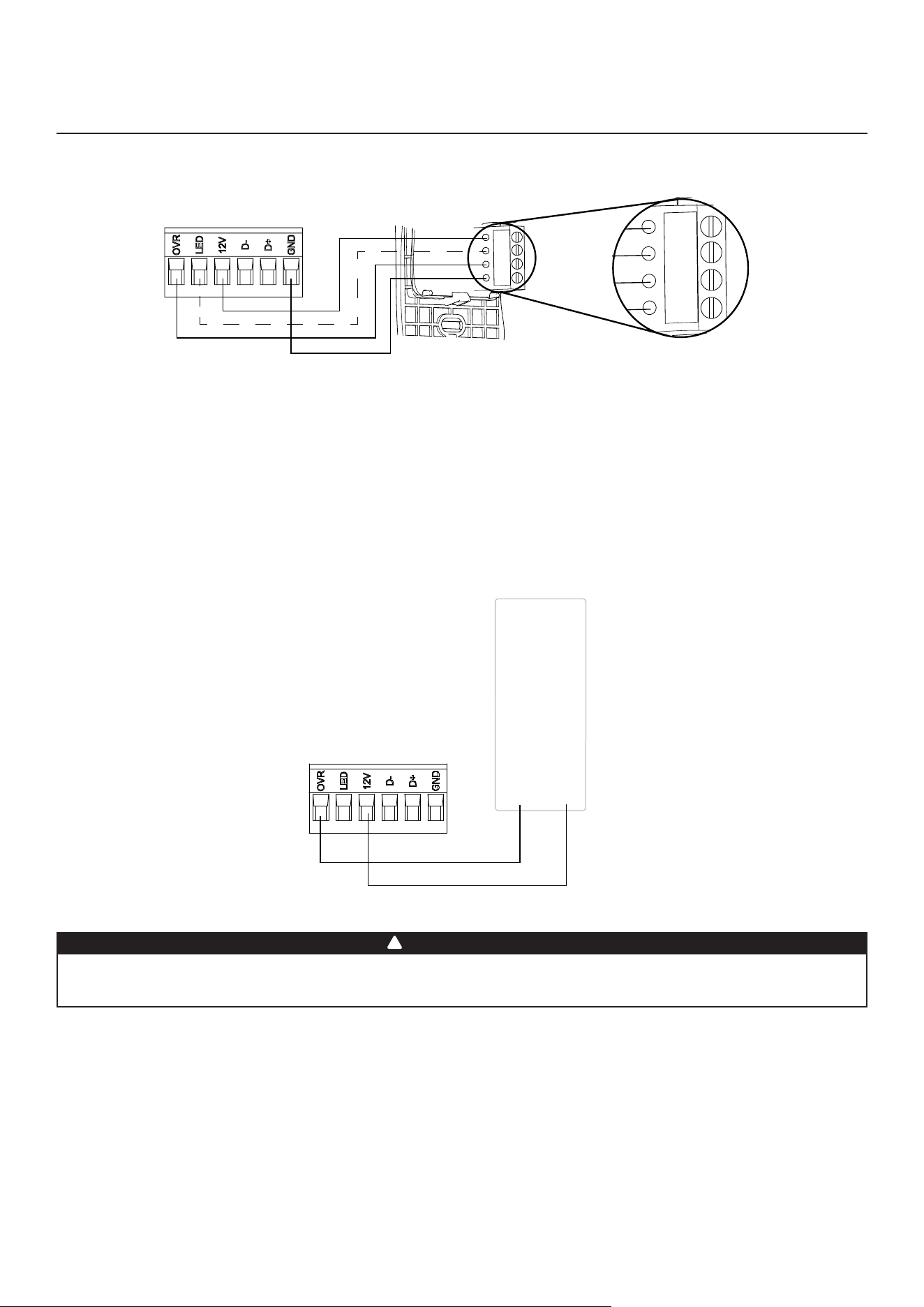
12
3.BRANCHEMENT
(SUITE)
3.2 b
rAncHemenT
de
lA
commAnde
murAle
AuxiliAire
opTionnelle
3.2.1 b
rAncHemenT
de
lA
commAnde
murAle
AuxiliAire
opTionnelle
20-40-60
Gnd
OVR
12V
LED
VC0243
Gnd
OVR
12V
LED
Lorsdelacon�gurationdel’optionOVRàl’écranACL,choisirl’unedeces3con�gurations:BAL(l’appareildemeure
balancétoutenfournissantundébitd’airmaximum),PER(l’appareilestlégèrementdébalancépuisquelemoteurde
distributionfonctionneàvitesseMAXtoutenfournissantuneventilationmaximaleàl’évacuation)etDIS(l’appareilest
débalancé puisque la distribution de l’air est constante malgré un besoin plus élevé en ventilation à l’évacuation).
NOTE: La commande murale auxiliaire peut être utilisée avec une connexion à 3 �ls en enlevant les signaux LED. Ce
branchementoptionnelnepermetpasuneinstallationavecplusd’unecommandemuraleauxiliairea�ndepermettre
la synchronisation adéquate de leurs LEDs pour un événement demandé par un pair. Seules les LEDs de la commande
muraleauxiliaireayantdemandél’événementdetypeminuterieserontmisesàjour.
3.2.2 b
rAncHemenT
de
lA
commAnde
murAle
AuxiliAire
opTionnelle
de
TYpe
conTAcT
sec
(
ex
.
minuTerie
mécAnique
)
Minuterie
mécanique
ou
Tout contact sec
12VOVR
VC0256F
Un branchement inadéquat qui envoie un signal 24 VCA au bornier à 6 positions (OVR, LED, 12V, D-, D+, GND)
peutendommagerdefaçonpermanentelecircuitdecommande.Véri�ersoigneusementlesconnexionsdes
�lsavantdemettrel’appareilsoustension.
AVERTISSEMENT
!
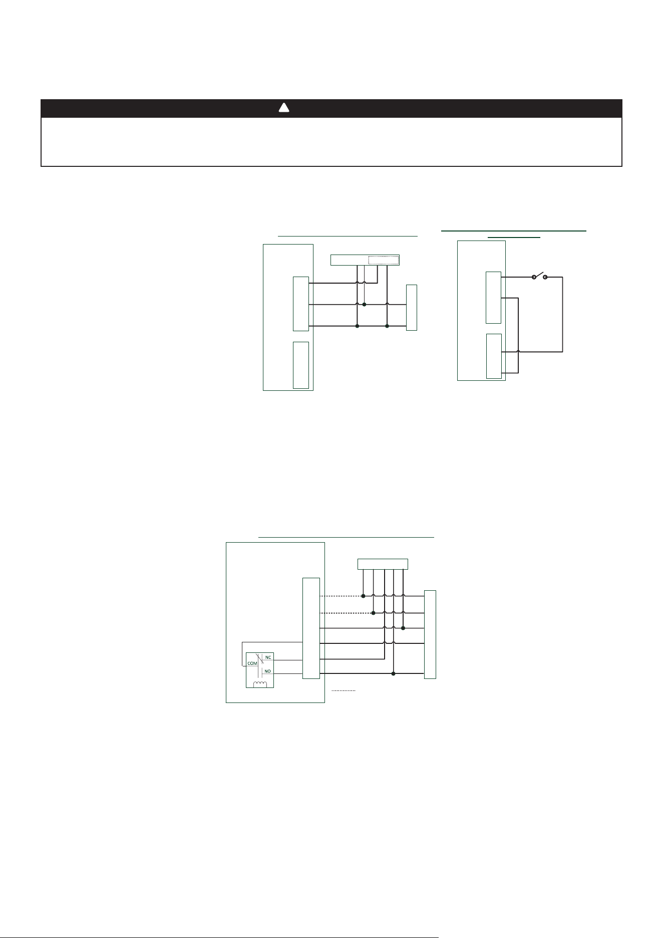
13
Nejamaisbrancheruncircuit120voltsc.a.auxbornesducâblagedusystèmecentralàairpulsé(méthode
standard). Utiliser seulement le circuit classe 2 du ventilateur du système central à air pulsé. L’appareil
est conçu pour des basses tensions uniquement; le brancher à une tension de 120 volts l’endommagerait
instantanément.
AVERTISSEMENT
!
3.3 r
AccordemenT
élecTrique
Au
sYsTème
cenTrAl
à
Air
pulsé
Borniers de la carte
électronique de
l’échangeur d’air
Y
W
C
G
R
Y W G R C
Thermostat du système central à air pulsé
Options de branchement avec système central à air pulsé
Vent
Y
W
C
Gf
G
R
J13
Logique
interne
Branchement optionnel pour synchronisation
Système central à air pulsé
3.3.1 f
oncTionnemenT
de
l
’
AppAreil
Avec
connexion
à
conTAcT
sec
3.3.2 i
nTerconnexion
de
l
’
AppAreil
Avec
un
sYsTème
cenTrAl
à
Air
pulsé
(r/c/G/G
f
)
Cesconnexionsdoiventêtreeffectuéessivousvoulezquel’appareilforcelefonctionnementduventilateurdusystème
central à air pulsé lors de la ventilation (se référer aux lignes continues dans le schéma ci-dessus).
NOTE : Cesconnexionssontrequisespourlacon�gurationd’installationT-4.Consulterlasection2.2pourobtenirplusde
détails.
3.3.3 s
YncHronisATion
Avec
le
foncTionnemenT
du
sYsTème
cenTrAl
à
Air
pulsé
La technologie Virtuo permet de synchroniser le fonctionnement de l’appareil avec le temps de fonctionnement du
systèmecentralàairpulsé.Celaévitequelesystèmecentralàairpulséfonctionneinutilementtoutenfournissantune
meilleure distribution d’air.
NOTE:LesconnexionsWetYdoiventêtreajoutéesauxconnexionsRetCpourinformerl’appareildufaitquelesystème
central à air pulsé est en fonction (se référer aux lignes pointillées dans le schéma ci-dessus).
VE0454F
Y
W
C
G
R
Y W G R C Acc+ Acc-
Thermostat du système central à air pulsé
Système central à air pulsé
Branchement pour connexion de type contact sec
1
1- External switch or any Dry-contact can be used to
activate Vent input if not available on the Thermostat
Borniers de
l’échangeur d’air
Branchement alternatif pour installation indépendante
de type contact sec
Vent
Y
W
C
Gf
G
R
J13
OVR
LED
12V
D-
D+
GND
J9
Commutateur externe ou
tout autre contact sec alternatif
Borniers de
l’échangeur d’air
Vent
Y
W
C
Gf
G
R
J13
OVR
LED
12V
D-
D+
GND
J9
Note : La synchronisation à un système central à air pulsé
avec W et Y n’est pas disponible avec cette configuration.
1 - Un commutateur externe ou tout autre contact sec peut être utilisé pour
activer l’entrée vent si non disponible sur le thermostat. Certains thermostats
offrent une sortie 24VCA à fil unique pour la ventilation accessoire. Elle peut
être branchée directement à l’entrée vent et par conséquent la connexion à
Acc- / R n’est pas requise.
Il est possible d’utiliser toute connexion à contact sec pour faire fonctionner l’appareil (ex. un thermostat équipé d’une sortie
ventilation optionnelle).
Une fois branché, l’appareil alternera
entre le mode Standby, lorsque le contact
est ouvert, et le mode sélectionné,
lorsque le contact est fermé. Choisir
parmices4con�gurations:minimum
(appareil fonctionnant à vitesse MIN),
intermittent (appareil fonctionnant
à vitesse MIN 20 min/h, puis selon
lacon�gurationsélectionnéepour
INT durant 40 min), auto* (appareil
fonctionnant selon la température
extérieure) et maximum (appareil
fonctionnantàvitesseMAX)àl’option
DRY sur l’écran ACL lorsque le contact
VENT est activé. Consulter la section 5
pour obtenir plus de détails.
* En mode auto, l’appareil fonctionnera
de la façon suivante :
• Sous -25°C = 10 min/h
• -25°C à -7°C = 20 min/h
• -7°C à 10°C = 40 min/h
• 10°C à 25°C = vitesse MIN
• 25°C à 28°C = 30 min/h
• 28°C à 33°C = 20 min/h
• Plus de 33°C = 10 min/h
NOTE : Cette option de contact sec prévaudra sur la commande murale principale;
nous ne recommandons pas l’utilisation d’une commande murale avec ce
type de connexion.
NOTE: Selon la con�guration d’installation des conduits et la température, il
pourrait être nécessaire que l’appareil fonctionne de façon continue. Se
référer à la section 2.2 pour obtenir plus de détails.
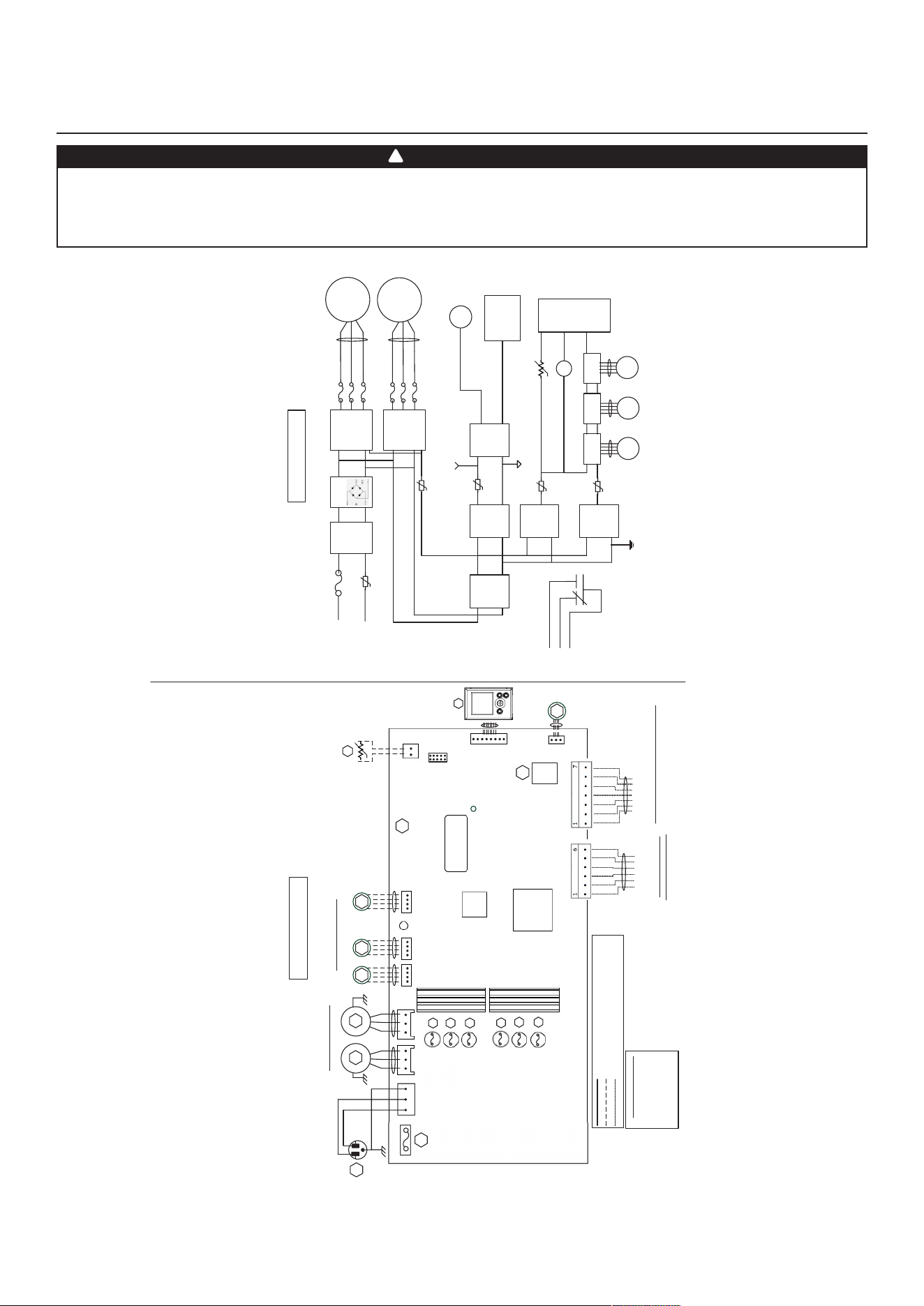
14
4.SCHÉMAÉLECTRIQUE
N
N
V
SCHÉMA LOGIQUE
CODE DES COULEURS
BLA BLANC
BLE BLEU
N NOIR
R ROUGE
V VERT
Fils de tension d’alimentaon installés en usine
Fils de basse tension installés en usine
Fils de basse tension installés sur place
(Évacua o n)
BLE
R
120VCA
60Hz
W1
V
1
ON
DEL
J1
M3
Moteurs pas à pas du volet
Y
M1
BLA
N
A1
ASSEMBLAGE
ÉLECTRONIQUE
PRINCIPAL
M1
Aliment.
élect.
(15VCD)
Ligne
Neutre
K1
G
Gf
CA
Ligne
Filtre
J1-2
F1
Haute tension
(120VCA)
J1-1
À J 2
MCU
K1
M3
À J 5
SCHÉMA ÉLECTRIQUE
BDM
1
J2 J3 J5 J6
J7
1
1 1 1
1
J7a
J15a
1
A2
ASSEMBLAGE
ACL
V
Moteurs venlateur
BLE
R
M2
M4 M5
(Distribuon)
(Recirc)
UCM
Numéro de série
d’iso laon
Transformateur
F usibles du moteur
F3
F6
F5
F7
V W GfC G R
* Câblage oponnel système central à air pulsé
(Isolé 24VCA
)
OVR
LED
12V
D-
D+
GND
Câblage des commandes
Thermistor
R1
RT1
(CTN)
Pont
IPM
Moteur 1
IPM
Moteur 2
F3
F2
M2
À J 3
F5
F4
K1
CTP3
Aliment.
isolée
(12VCD)
Aliment.
isolée
(3.3VCD)
J9
J13
Aliment.
logique
(3.3VCD)
CTP2
À J 9
Aliment.
logique
(12VCD)
M4
À J 6
M5
Moteur
pas à pas
À J 7
CTP6
CTP4
À J 13
R
TH1
À J 7a
(R1)
Assemblage
ACL
Mise à la terre
isolée
Mise à la terre
À J 15a
(A2)
J14
F2
F4
J16a
M6
Venlateur
refroidissement
F7
F6
M6
À J 16a
F1
5A/125VCA
*Seul ement
pour les
modè les
210 - 230 pi
3
/min
*Seulement pour
les modèles
210 - 230 pi/min
(Distribuon)
(Évacua o n)
Relais système
central à air
pulsé
principales et auxiliaires
Moteur
pas à pas
Moteur
pas à pas
• Dangerd’électrocution.Toujoursdébrancherl’appareilavantd’effectuerlestravauxd’entretienouderéparation.
• Cet appareil est muni d’une protection contre les surcharges (fusible). Un fusible brûlé indique une surcharge
ou un court-circuit. Si le fusible brûle, débrancher l’appareil de la prise de courant. Cesser d’utiliser l’appareil et
communiquer avec le support technique.
AVERTISSEMENT
!
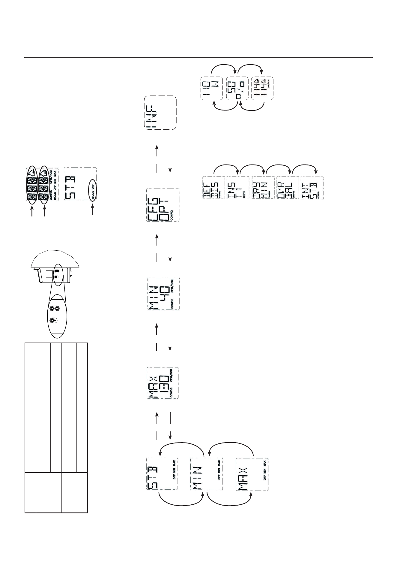
15
5.NAVIGATIONÀL’ÉCRANACL
APPUYER SUR LE BOUTON
OK POUR CONFIRMER LA
SÉLECTION DU MODE.
APPUYER SUR LE BOUTON OK
DURANT 4 SECONDES POUR
MODIFIER LA CONFIGURATION
MAXPI³/MIN.
LADONNÉEMAXPI³/MIN
CLIGNOTERA.
UTILISER LE BOUTON + POUR
AUGMENTER LA VALEUR OU LE
BOUTON - POUR DIMINUER LA
VALEUR.
APPUYER SUR LE BOUTON OK
POUR CONFIRMER LA VALEUR.
APPUYER SUR LE BOUTON OK
DURANT 4 SECONDES POUR
MODIFIER LA CONFIGURATION
DES OPTIONS.
POUR CHAQUE
CONFIGURATION
D’OPTION, UTILISER
LE BOUTON + POUR
FAIRE DÉFILER
VERS LE HAUT
LES OPTIONS
DISPONIBLES OU
LE BOUTON -
POUR FAIRE
DÉFILER VERS LE
BAS LES OPTIONS
DISPONIBLES. UNE
FOIS LA SÉLECTION
DE L’OPTION FAITE,
APPUYER SUR
LE BOUTON OK
POUR CONFIRMER
LA SÉLECTION.
LA PROCHAINE
CONFIGURATION
D’OPTION
S’AFFICHERA.
APPUYER SUR LE BOUTON OK
POUR CONFIRMER LA VALEUR.
UTILISER LE BOUTON + POUR
AUGMENTER LA VALEUR OU LE
BOUTON - POUR DIMINUER LA
VALEUR.
LA DONNÉE MIN PI³/MIN
CLIGNOTERA.
APPUYER SUR LE BOUTON OK
DURANT 4 SECONDES POUR
MODIFIER LA CONFIGURATION
MIN PI³/MIN.
VQ0211
VQ0209
VQ021
0
+
-
VQ0205
VQ0207
VQ0201
+
+
-
-
+
-
+
-
VQ0
19
7
VQ0202
VQ0
19
9
VQ0
19
8
VQ0200
+
-
OK
VD0492
Bouton OK Pourcon�rmerunesélection.
Bouton + Pour augmenter une valeur.
Pourfairedé�lerunesélectionverslehaut.
Bouton - Pour diminuer une valeur.
Pourfairedé�lerunesélectionverslebas.
VQ0203
VQ0212
Indique le
mode actuel
Indique le
débit d’air
frais
Indique le
débit d’air
vicié
APPUYER SUR LE BOUTON OK
POUR CHANGER LE MODE.
UTILISER LE BOUTON + OU LE
BOUTON - POUR SÉLECTIONNER
LE MODE SOUHAITÉ.
APPUYER SUR LE BOUTON + OU LE BOUTON -POURMODIFIERMAXPI³/MIN, MIN PI³/MIN OU LA
CONFIGURATION DES OPTIONS.
VQ0213
APPUYER SUR LE BOUTON OK
DURANT 4 SECONDES POUR
ACCÉDER À L’INFORMATION
COMPLÉMENTAIRE.
+
+
-
-
AFFICHE LE %
DE TEMPS DE
FONCTIONNEMENT
DE L’APPAREIL
(PAR HEURE)
POUR LE MODE DE
FONCTIONNEMENT
SÉLECTIONNÉ.
AFFICHE LES
DÉBITS D’AIR DE
L’APPAREIL.
APPUYER SUR LE
BOUTON OK POUR
QUITTER L’INFORMATION
COMPLÉMENTAIRE.
Dans l’exemple ci-dessus, l’appareil
fournit 114 pi
3
/min avec une
consommation électrique de 110 W
durant 50 % de l’heure. Le débit d’air
net est de 57 pi
3
/min(50%X114),
la consommation électrique nette est
d’environ55W(50%X110).
VQ0214
VQ0215
VQ0216
NOTE :Selonlemodèleetlacon�gurationdel’appareil,certainsmenuspeuventnepasêtredisponibles.
+
-
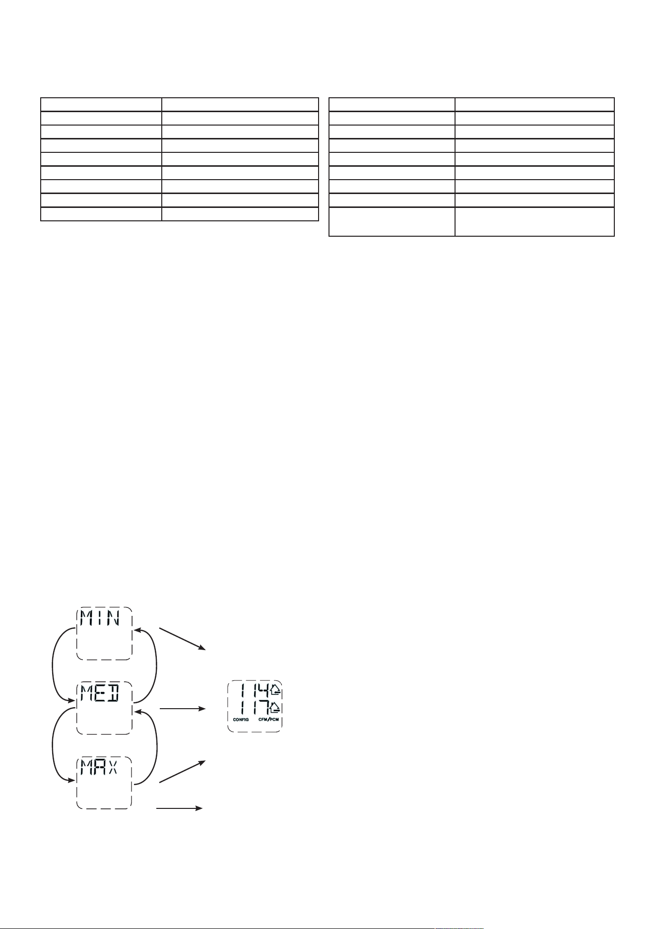
16
5.3 m
odificATion
des
réGlAGes
5.3.1 p
rocédure
pour
modifier
le
réGlAGe
min
pi
³/
min
• Aller à MIN à l’aide de (+/-) et appuyer sur le bouton OK durant 4 secondes.
• Utiliser (+/-) pour augmenter/diminuer
pi³/min
etOKpourcon�rmer.
5.3.2 p
rocédure
pour
modifier
le
réGlAGe
mAx
pi
³/
min
• AlleràMAXàl’aidede(+/-)etappuyersurleboutonOKdurant4secondes.
• Utiliser (+/-) pour augmenter/diminuer
pi³/min
etOKpourcon�rmer.
5.3.3 p
rocédure
pour
modifier
le
réGlAGe
des
opTions
• Aller à CFG OPT à l’aide de (+/-) et appuyer sur le bouton OK durant 4 secondes.
5.2 p
remier
démArrAGe
de
l
’
AppAreil
p
répArATion
Pour obtenir des données précises, suivre d’abord les étapes suivantes:
• Sceller tous les conduits du réseau avec du ruban à conduit. Fermer toutes les portes et fenêtres.
• Arrêtertouslesdispositifsd’évacuationd’airtelsquehottedecuisinière,ventilateursdesalledebainsousécheuse.
• Si l’installation est reliée de quelque façon que ce soit avec un conduit du système central à air pulsé, s’assurer que le
ventilateurdecelui-ciestenmarche.Sinon,nepasfairefonctionnerleventilateurdusystèmecentralàairpulsé.
p
rocédure
d
’
AuTo
-
bAlAncemenT
• Brancher l’appareil et attendre que le pi
3
/minmaximums’af�cheàl’écranACL.Sil’appareilestplusfroidquelatempérature
ambiante, il est normal que le premier démarrage soit plus long (60 s) puisque les moteurs doivent préchauffer. Se référer à la
section8.1sileserreursE22ouE32s’af�chent.
• Le pi
3
/minmaximums’af�cheraàl’écranACL.Utiliser(+/-)pourajusterlepi
3
/minetOKpourcon�rmer.
• Le pi
3
/minminimums’af�cheraàl’écranACL.Utiliser(+/-)pourajusterlepi
3
/minetOKpourcon�rmer.
• La maison qui clignote à l’écran ACL indique le côté qui limite le débit d’air (air frais ou air vicié). Si le débit d’air atteint est
insuf�sant,l’installateurpeutaméliorerl’installationpouraugmenterledébitd’air.
s
élecTion
de
lA
confiGurATion
d
’
insTAllATion
• INSs’af�cheraàl’écranACL.ChoisirparmiT-1,T-2,T-3,T-4ouT-5selonlacon�gurationd’installation(consulterlasection2.2
pour plus de détails).
• L’auto-balancement est complété.
5.1 é
crAn
Acl
AFFICHAGE DÉFINITION
STB Mode attente
MED Vitesse MED
INT Mode intermittent
REC Mode recirculation (vitesse Min, Med ou Max)
AUT Mode AUTO
SMT Mode SMART
OVR 20 Auxiliaire 20 min
OVR 40 Auxiliaire 40 min
5.3.4 p
rocédure
pour
modifier
le
réGlAGe
des
débiTs
d
’
Air
indépendAnTs
• Appuyer simultanément sur les boutons (+/-) durant 4 secondes.
VQ0217
VQ0218
VQ0219
VQ0220
+
+
-
-
OK
OK
OK
+
LORSQUEMAXS’AFFICHE,
APPUYER SUR LE BOUTON
+
POUR SORTIR DU RÉGLAGE DES
DÉBITS D’AIR INDÉPENDANTS.
LA VALEUR DU DÉBIT D’AIR FRAIS CLIGNOTERA.
APPUYER SUR LE BOUTON + OU SUR LE BOUTON -
POUR AUGMENTER/DIMINUER LA VALEUR.
APPUYER SUR LE BOUTON OK.
LA VALEUR DU DÉBIT D’AIR VICIÉ CLIGNOTERA.
APPUYER SUR LE BOUTON + OU SUR LE BOUTON -
POUR AUGMENTER/DIMINUER LA VALEUR.
APPUYER SUR LE BOUTON OK.
AFFICHAGE DÉFINITION
OVR 60 Auxiliaire 60 min
OVR CNT Auxiliaire par contact sec
AHU Se référer à la section 6.3 pour plus de détails
HUM Auxiliaire humidistat ou déshumidistat
TUR Mode turbo
OTH ModeabsenceouModeplani�cation
DEF Mode dégivrage
EXXouWXX
(XXréfèreaunumérodel’erreurou
de l’avertissement)
Se référer à la section 8 pour l’explication de
chaque erreur/avertissement
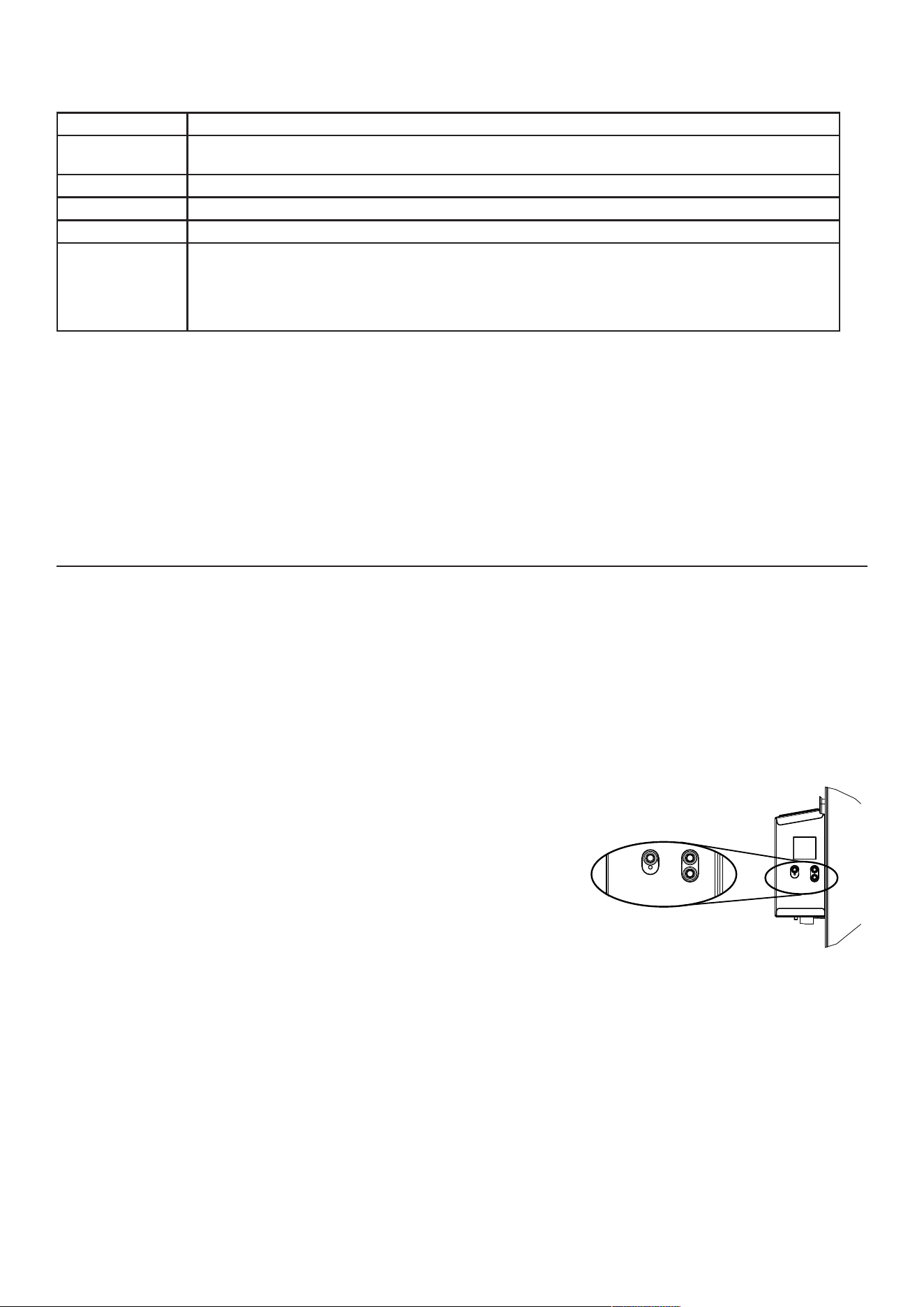
17
6.UTILISERVOTREAPPAREIL
Cette unité de ventilation balancée introduira de l’air frais dans votre demeure tout en évacuant l’air vicié. À l’aide de son
modulederécupérationd’énergie/dechaleur,l’appareilrécupèreunegrandepartiedelachaleuroudel’énergieprésente
dansl’airintérieurouextérieur,selonlessaisons,a�nd’accroîtreleconfortetl’ef�cacitéénergétiquedurantlespériodes
de chauffage et de climatisation. Grâce à Virtuo Air Technology
TM
,cetappareils’ajusteauxvariationsdesonenvironnement
de façon autonome, s’assurant ainsi de fournir un niveau adéquat de ventilation et de qualité d’air. Cet appareil comprend
égalementdesmodesautomatiques(AUTOouSMART)quigèrentdefaçonautonomeleniveaudeventilationrequisen
fonction des conditions intérieures et/ou extérieures. Dans les régions plus froides, l’appareil exécutera, à certains intervalles,
undégivragediscretdumodulederécupérationa�ndemaintenirperformanceetconfort.
6.1 v
oTre
sYsTème
de
venTilATion
6.2 c
ommAnde
inTéGrée
Tous les appareils sont munis d’une commande intégrée, située à l’avant du compartiment électrique. Pour plus de commodité,
cesappareilspeuventêtrecontrôlésaumoyend’unecommandemuraleoptionnelleouduthermostatdusystèmecentralàair
pulsé équipé d’une sortie pour activation d’un ventilateur externe.
+
-
OK
VD0492
s
élecTion
du
mode
1. Pour changer le mode, utiliser (+/-) pour accéder à l’écran Mode. Appuyer sur
OKpourmodi�erlemodeetutiliser(+/-)pourchangerlemode(Standby,Min,
Max).
2. Appuyersur OK pourcon�rmer lasélection.Lesdébitsd’airs’af�cheront
tantpourlemodeMINquepourlemodeMAX.
NOTE : Si une commande murale auxiliaire optionnelle ou le thermostat du
systèmecentralàairpulsééquipéd’unesortiepouractivationd’un
ventilateur externe est utilisé, il prévaudra sur la commande intégrée.
6.3 A
fficHAGe
du
mode
AHu
Selonlacon�gurationdel’appareilet/oul’installation,l’appareilpourraitnepasêtrecapabled’atteindrelepi
3
/min minimum
réglédésiré.Cettesituationpourraitsurveniraveclescon�gurationsinstalléesT-2àT-5àcausedelapressionstatiquedeAHUet
d’un pi
3
/minminimumréglésous75.Dansuntelcas,AHUXX(XXréférantàlavaleurminimalesouhaitéeenpi
3
/min)s’af�chera
à l’écran ACL. En mode AHU, l’appareil fonctionne en mode intermittent pour atteindre la valeur minimale souhaitée en pi
3
/min.
La durée du mode intermittent varie selon la valeur minimale souhaitée en pi
3
/min.
Si un changement est effectué aux conduits, réinitialiser les réglages pour recommencer le test de débit d’air.
p
rocédure
pour
réiniTiAliser
les
réGlAGes
AppuyersimultanémentsurlesboutonsOKet(-)durant4secondes.Utiliser(+/-)poursélectionnerYesouNoetOKpourcon�rmer.
Effectuer la procédure d’auto-balancement.
NOTE:Siaucunesélectionn’estcon�rméeen10minutes,l’appareilquitteralemenusanssauvegarderlesmodi�cations.
* Réglage en usine
Options Con�gurationsdisponibles
DEF (Dégivrage) DIS* (Discrétion - dégivrage sans variation de vitesse pour plus de confort),
PLU (Plus - dégivrage prolongé pour les régions plus froides)
INS (Installation) T-1,T-2,T-3,T-4*,T-5 (Consulter la section 2.2)
DRY (Contact sec) MIN* (Minimum), INT (Intermittent), AUT (AUTO), MAX (Maximum) (Consulter la section 3.3.1)
OVR (Auxiliaire) BAL* (Balancé), PER (Perfo), DIS (Discrétion) (Consulter la section 3.2.1)
INT (Intermittent) STB* (Attente - 20 min à vitesse MIN et 40 min en mode attente), REC** (Recirculation -
20minàvitesseMINet40minenmoderecirculation)**REC(Recirculation)con�gurationnon
disponiblepourlescon�gurationsd’installationT-4etT-5.
NOTE:Selonlacon�gurationd’installationdesconduitsetlatempérature,ilpourraitêtrenécessaireque
l’appareil fonctionne de façon continue. Se référer à la section 2.2 pour obtenir plus de détails.
5.4 r
éiniTiAlisATion
des
réGlAGes
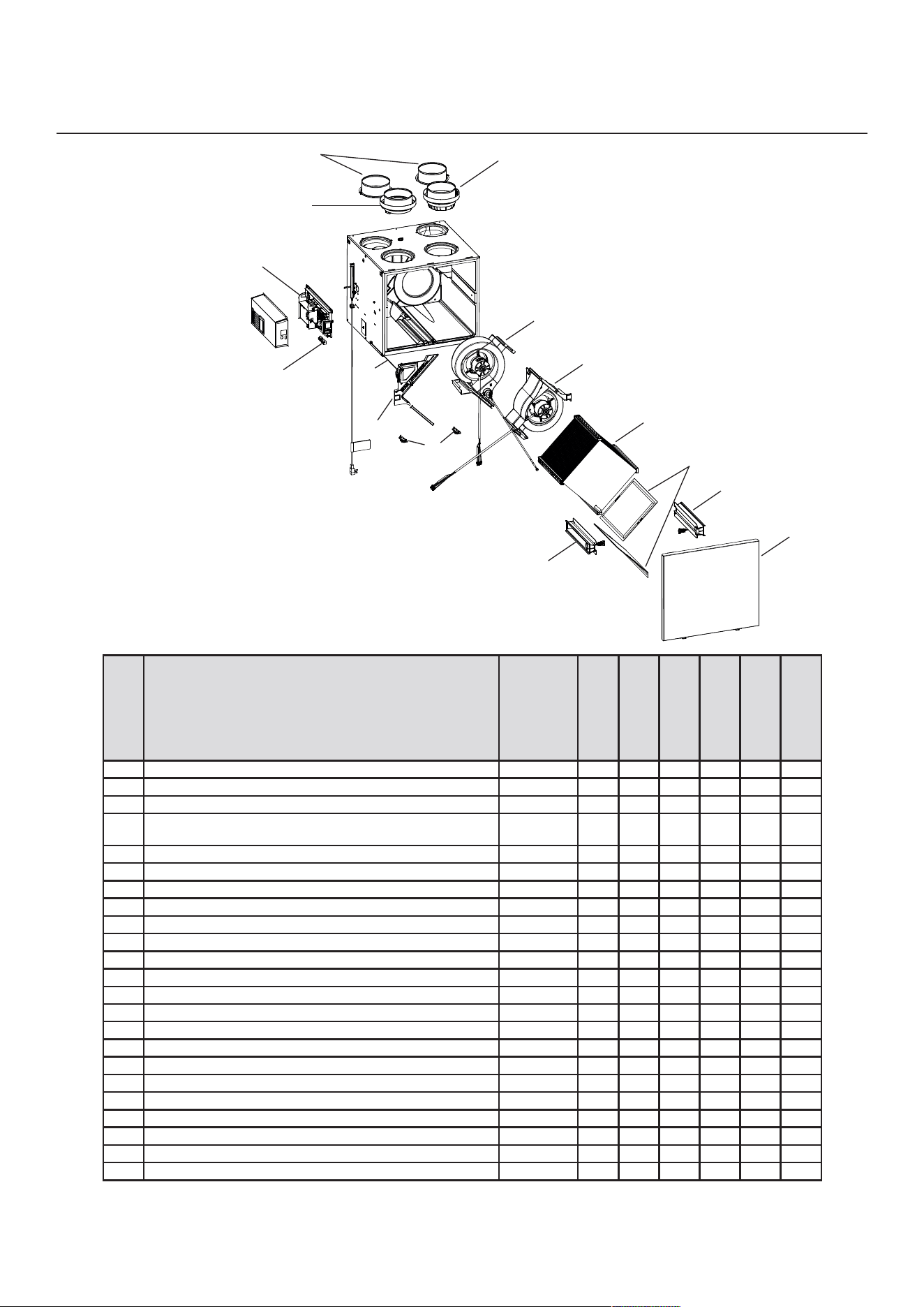
18
* Non illustré.
**Consulterlapagesuivantepourobtenirlenumérodepiècecorrespondantaumodèledel’appareildeventilation.
r
éf
. d
escripTion
n
uméro
de
pièce
1 Bouche de 6 po (côté chaud) SV66139 2 2 2 2 2 2
2 Bouche mélallique 6 po volet motorisé SV66135 1 1 1 1 1 1
3 Assemblageélectronique(modèles180) SV68027** 1 1
4
Assemblage électronique avec ventilateur de
refroidissement(modèles210-230)
SV68028** 1 1 1 1
5 Ensembledeventilateurderefroidissement(modèles210-230) SV68031 1 1 1 1
6 Borniers SV66145 1 1 1 1 1 1
7 Assemblage bouche évacuation 6 po SV66137 1 1 1 1 1 1
8 Loquets-crochets pour porte SV61218 1 1 1 1 1 1
9 Thermistor SV66134 1 1 1 1 1 1
10 Volet recirculation avec thermistor SV68029 1 1 1 1 1 1
11 Ventilateurévacuationavecvolet(modèles180) SV68022 1 1
12 Ventilateurévacuationavecvolet(modèles210-230) SV68024 1 1 1 1
13 Assemblageventilateuralimentation(modèles180) SV68021 1 1
14 Assemblageventilateuralimentation(modèles210-230) SV68023 1 1 1 1
15 Noyau VRE 75 % SV68018 1 1 1
16 Noyau VRC 75 % SV68019 1 1 1
17 Ensembledeglissièresdenoyauavecvis SV68026 1 1 1 1 1 1
18 Ensemble�ltresMERV8 SV68020 1 1 1 1 1 1
19 Porte SV68030 1 1 1 1 1 1
20 Volet évacuation SV68025 1 1 1 1 1 1
* Ensemble quincaillerie SV66146 1 1 1 1 1 1
* Fusible pour carte électronique SV66147 1 1 1 1 1 1
* Boyau ½ po SV00592 1 1 1
VL0091
B
C
D
E
F
G
H
I
J
K
LM
N
A180H75RT
V180H75RT
A180E75RT
V180E75RT
A230H75RS
V230H75RS
A230H75RT
V230H75RT
A210E75RS
V210E75RS
A210E75RT
V210E75RT
P
O
Q
R
R
S
U
T
7. PIÈCES DE REMPLACEMENT
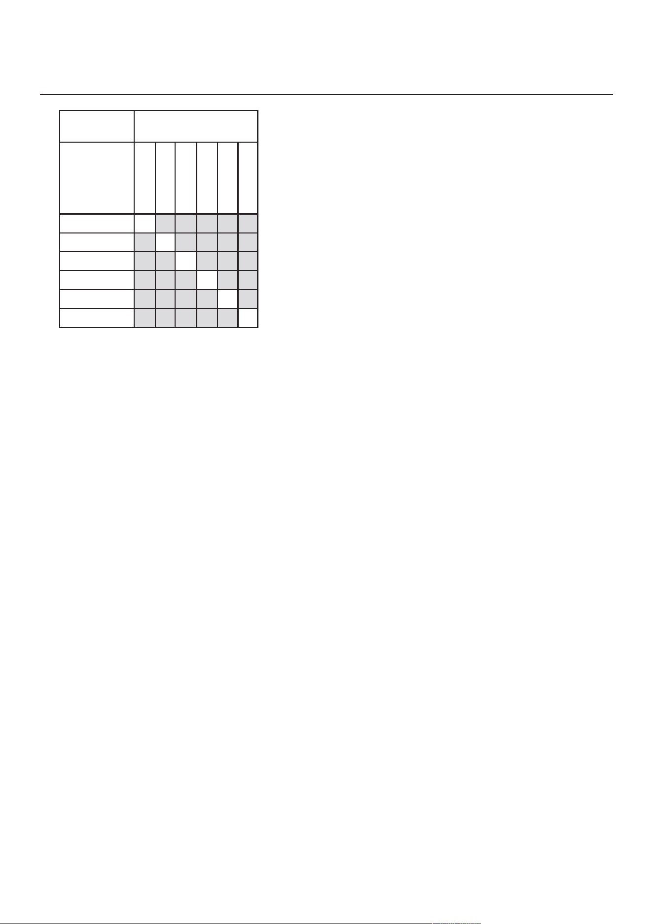
19
7.PIÈCESDEREMPLACEMENT(
Suite
)
p
ièces
de
remplAcemenT
eT
service
Pourassurerlebonfonctionnementdevotreappareil,vousdeveztoujoursutiliserdespièces
d’origineprovenantdufabricant.Lespiècesd’originedufabricantsontspécialementconçues
poursatisfairetouteslesnormesdecerti�cationdesécuritéapplicables.Leurremplacement
par des pièces ne provenant pas du fabricant pourrait ne pas assurer la sécurité de
l’appareil,entraîneruneréductionsévèredesperformancesainsiqu’unrisquededéfaillance
prématurée.Aussi,lefabricantrecommandedetoujoursvousréférer àuneentreprisede
servicescompétenteetreconnueparlefabricantpourvospiècesderemplacementetappels
de service.
m
odèle
de
l
’
AppAreil
de
venTilATion
n
uméro
de
pièce
de
l
’
AssemblAGe
élecTronique
SV68027-01
X
SV68027-02
X
SV68028-01
X
SV68028-02
X
SV68028-03
X
SV68028-04
X
A/V180H75RT
A/V180E75RT
A/V230H75RS
A/V230H75RT
A/V210E75RS
A/V210E75RT
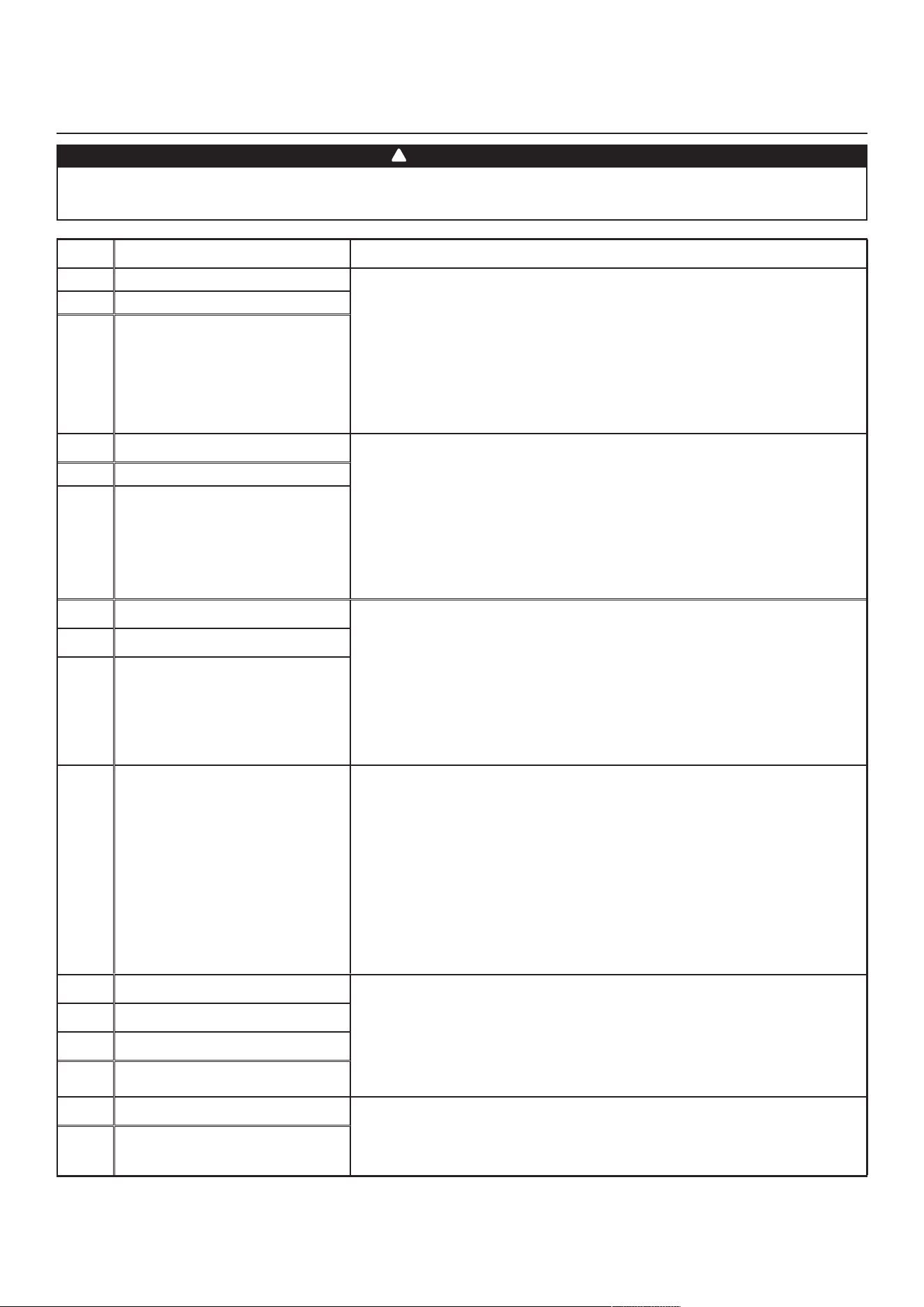
20
8. DÉPANNAGE POUR INSTALLATEUR
Le port de lunettes et de gants de sécurité est recommandé puisque certaines prodédures de diagnostic
doiventêtreeffectuéesalorsquel’appareilfonctionne.Porteruneattentionparticulièreauxpiècesmobileset
auxcomposantesélectriquesa�nd’évitertoutrisquedeblessure.
AVERTISSEMENT
!
e
rreur
d
eSCription
S
olution
E01
Position volet alimentation
ÉTAPE1:Débrancherl’appareil,véri�erlesystèmedevolets,enlevertoutobstacle
indésirableousaleté(sinécessaire,enleverles�ltresetlenoyaupouraccéderau
systèmedevolets).Brancherl’appareil.
Sil’ÉTAPE1n’apasrégléleproblème,effectuerl’ÉTAPE2:Ouvrirle
compartimentélectrique,véri�ersileconnecteurJ5(blanc)estbieninséré,
véri�ers’ilyades�lsmal�xés.
Sil’ÉTAPE2n’apasrégléleproblème,effectuerl’ÉTAPE3:Silevoletnebougepas
du tout, débrancher J7 (rouge) de l’assemblage électronique, connecter le connecteur
blancdusystèmedevoletsdansJ7.Silevoletbouge(maisle
systèmeindiqueencoreuneerreur),l’assemblageélectroniquedoitêtreremplacé.
Sinon,remplacerlesystèmedevolets.
E02
Arrêtvoletalimentation
E03
Voletalimentation
E05
Position volet évacuation
ÉTAPE1:Débrancherl’appareil,véri�erlesystèmedevolets,enlevertoutobstacle
indésirableousaleté(sinécessaire,enleverles�ltresetlenoyaupouraccéderau
systèmedevolets).Brancherl’appareil.
Sil’ÉTAPE1n’apasrégléleproblème,effectuerl’ÉTAPE2:Ouvrirle
compartimentélectrique,véri�ersileconnecteurJ7(rouge)estbieninséré,
véri�ers’ilyades�lsmal�xés.
Sil’ÉTAPE2n’apasrégléleproblème,effectuerl’ÉTAPE3:Silevoletnebougepas
du tout, débrancher J5 (blanc) de l’assemblage électronique, connecter le connecteur
blancdusystèmedevoletsdansJ5.Silevoletbouge(maisle
systèmeindiqueencoreuneerreur),l’assemblageélectroniquedoitêtreremplacé.
Sinon,remplacerlesystèmedevolets.
E06
Arrêtvoletévacuation
E07
Voletévacuation
E09
Position volet recirculation
ÉTAPE1:Débrancherl’appareil,véri�erlesystèmedevolets,enlevertoutobstacle
indésirableousaleté(sinécessaire,enleverles�ltresetlenoyaupouraccéderau
systèmedevolets).Brancherl’appareil.
Sil’ÉTAPE1n’apasrégléleproblème,effectuerl’ÉTAPE2:Ouvrirle
compartimentélectrique,véri�ersileconnecteurJ6(bleu)estbieninséré,
véri�ers’ilyades�lsmal�xés.
Sil’ÉTAPE2n’apasrégléleproblème,effectuerl’ÉTAPE3:Silevoletnebougepas
du tout, débrancher J5 (blanc) de l’assemblage électronique, connecter le connec-
teurbleudusystèmedevoletsdansJ5.Silevoletbouge(maislesystèmeindique
encore une erreur), l’assemblage électronique doit être remplacé. Sinon, remplacer le
systèmedevolets.
E10
Arrêtvoletrecirculation
E11
Voletrecirculation
E22
Débitd’airalimentation
ÉTAPE1:Débrancherl’apareil.Effectueruneinspectionvisuelledusystèmedevoletsà
l’alimentation.Nettoyerles�ltres,lesgrillesdedistributionetlabouched’aspirationextérieure.
Véri�erleconduitpours’assurerqu’iln’estpasécraséouplié.Brancherl’appareil.
Sil’ÉTAPE1n’apasrégléleproblème,effectuerl’ÉTAPE2:Enleverleconduit
d’alimentation.Àl’écranACL,sélectionnerMAXpourvéri�ersil’appareilestcapable
d’atteindreledébitsélectionné.Sic’estlecas,revoirletrajetduconduit.
Sil’ÉTAPE2n’apasrégléleproblème,effectuerl’ÉTAPE3:Àl’écranACL,
sélectionnerlesvaleursderéglagedesdébitsMINetMAXetréinitialiserl’appareil.
LavaleurdedébitMAXs’af�cheraàl’écranACL.SiledébitMAXestsupérieurau
débitMAXsouhaité,réglerlesdébitsMAXetMIN.
Sil’ÉTAPE3n’apasrégléleproblème,effectuerl’ÉTAPE4:Remplacerleventilateurà
l’alimentation et répéter l’ÉTAPE 3.
Sil’ÉTAPE4n’apasrégléleproblème,effectuerl’ÉTAPE5:Remplacerl’assemblage
électronique. Se référer également à la section 8.1.
E23
Moteuralimentation(surcharge)
ÉTAPE 1 : Débrancher/brancher l’appareil.
Sil’ÉTAPE1n’apasrégléleproblème,effectuerl’ÉTAPE2:Retirerlenoyauet
enlever tout obstacle ou saleté de la roue du ventilateur.
Sil’ÉTAPE2n’apasrégléleproblème,effectuerl’ÉTAPE3:DébrancherJ2(blanc)et
connecterunsystèmedeventilateurderemplacement.Sicelafonctionne,
remplacer le ventilateur à l’alimentation.
Sil’ÉTAPE3n’apasrégléleproblème,effectuerl’ÉTAPE4:Remplacerl’assemblage
électronique.
E27
Moteuralimentation(durée)
E28
Moteuralimentation(rétroaction)
E29
Moteuralimentation(démarrage)
E24
Moteuralimentation(surtension)
ÉTAPE 1 : Débrancher/brancher l’appareil. La sous-tension et la surtension peuvent
êtredétectéesparuneimportanteuctuationdel’alimentation
électrique de la maison et peuvent arrêter le moteur pour le protéger.
Sil’ÉTAPE1n’apasrégléleproblème,effectuerl’ÉTAPE2:Remplacerl’assemblage
électronique.
E25
Moteuralimentation(sous-tension)
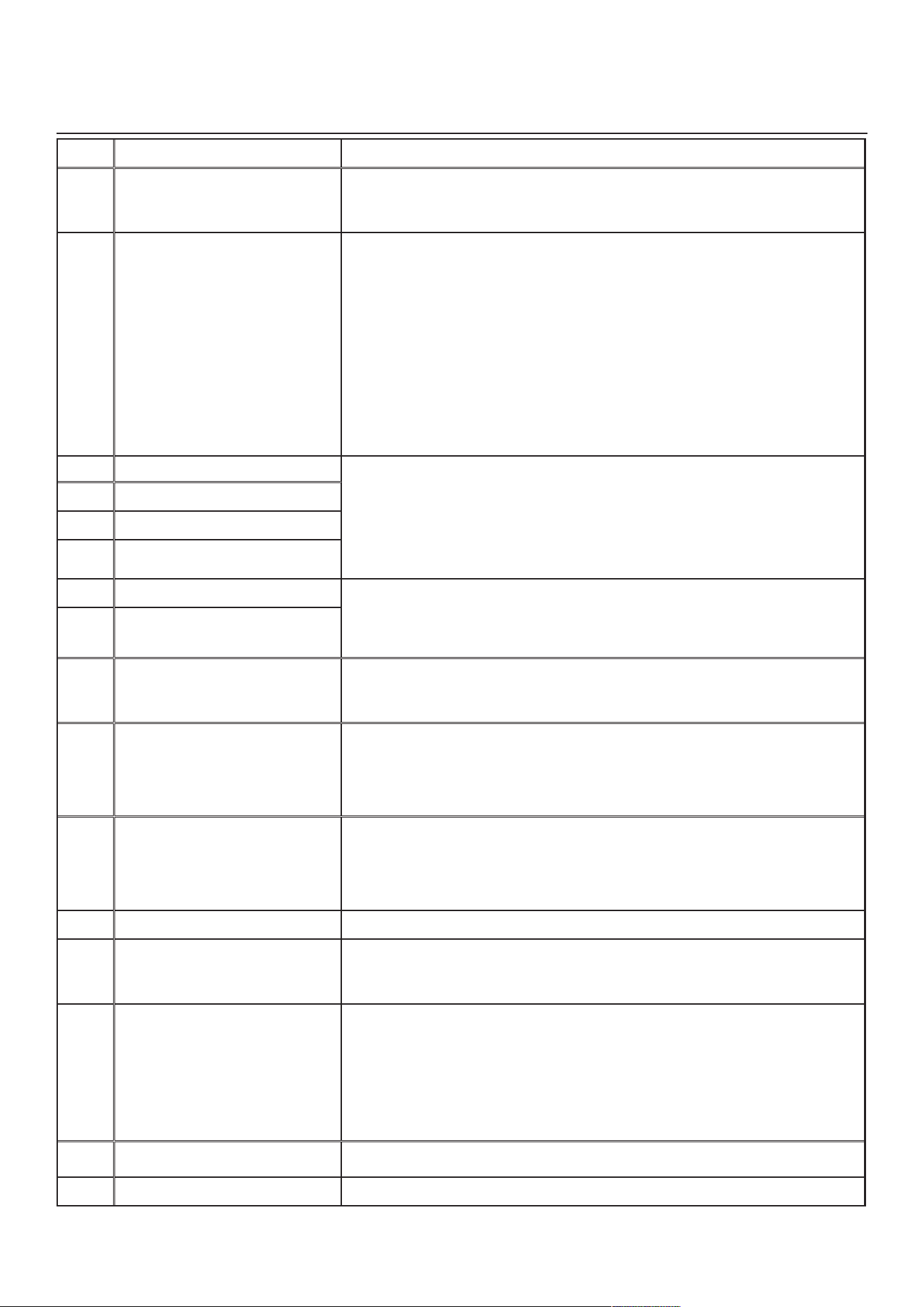
21
e
rreur
d
eSCription
S
olution
E26
Moteuralimentation(surchauffe)
ÉTAPE 1 : Valider si l’échangeur d’air est exposé à des températures ambiantes se
situant dans les limites de fonctionnement (voir p. 4)
Sil’ÉTAPE1n’apasrégléleproblème,effectuerl’ÉTAPE2:Remplacerl’assemblage
électronique.
E32
Débitd’airévacuation
ÉTAPE1:Débrancherl’appareil.Effectueruneinspectionvisuelledu systèmedevoletsà
l’évacuation.Nettoyerles�ltres,lesgrillesdedistributionetlabouched’évacuationextérieure.
S’assurer qu’il n’y a pas de volet anti-retour dans la bouche d’évacuation puisqu’il peut geler
enhiver.Véri�erleconduitpours’assurerqu’iln’estpasécraséouplié.Brancherl’appareil.
Sil’ÉTAPE1n’apasrégléleproblème,effectuerl’ÉTAPE2:Enleverleconduit
d’alimentation.Àl’écranACL,sélectionnerMAXpourvéri�ersil’appareilestcapable
d’atteindreledébitsélectionné.Sic’estlecas,revoirletrajetduconduit.
Sil’ÉTAPE2n’apasrégléleproblème,effectuerl’ÉTAPE3:Àl’écranACL,sélectionner
lesvaleursderéglagedesdébitsMINetMAXetréinitialiserl’appareil.Lavaleurde
débitMAXs’af�cheraàl’écranACL.SiledébitMAXestsupérieuraudébitMAX
souhaité,réglerlesdébitsMAXetMIN.
Sil’ÉTAPE3n’apasrégléleproblème,effectuerl’ÉTAPE4:Remplacerleventilateurà
l’évacuation et répéter l’ÉTAPE 3.
Sil’ÉTAPE4n’apasrégléleproblème,effectuerl’ÉTAPE5:Remplacerl’assemblage
électronique. Se référer également à la section 8.1.
E33
Moteurévacuation(surcharge)
ÉTAPE 1 : Débrancher/brancher l’appareil.
Sil’ÉTAPE1n’apasrégléleproblème,effectuerl’ÉTAPE2:Retirerlenoyauetenlever
tout obstacle ou saleté de la roue du ventilateur.
Sil’ÉTAPE2n’apasrégléleproblème,effectuerl’ÉTAPE3:DébrancherJ3(rouge)et
connecterunsystèmedeventilateurderemplacement.Sicelafonctionne,remplacerle
ventilateur à l’évacuation.
Sil’ÉTAPE3n’apasrégléleproblème,effectuerl’ÉTAPE4:Remplacerl’assemblage
électronique.
E37
Moteurévacuation(durée)
E38
Moteurévacuation(rétroaction)
E39
Moteurévacuation(démarrage)
E34
Moteurévacuation(surtension)
ÉTAPE 1 : Débrancher/brancher l’appareil. La sous-tension et la surtension peuvent
êtredétectéesparuneimportanteuctuationdel’alimentationélectriquedelamaison
et peuvent arrêter le moteur pour le protéger.
Sil’ÉTAPE1n’apasrégléleproblème,effectuerl’ÉTAPE2:Remplacerl’assemblage
électronique.
E35
Moteurévacuation(sous-tension)
E36
Moteurévacuation(surchauffe)
ÉTAPE 1 : Valider si l’échangeur d’air est exposé à des températures ambiantes se
situant dans les limites de fonctionnement (voir p. 4)
Sil’ÉTAPE1n’apasrégléleproblème,effectuerl’ÉTAPE2:Remplacerl’assemblage
électronique.
E40
Thermistor air extérieur
ÉTAPE1:Véri�ersilethermistorestbienconnectédansleconnecteurJ7A.
Sil’ÉTAPE1n’apasrégléleproblème,effectuerl’ÉTAPE2:DébrancherleconnecteurJ7A
etvéri�ersilarésistancemesurée(connecteurduthermistor)sesitueentre5Kohmset
120 Kohms. Si ce n’est pas le cas, remplacer le thermistor.
Sil’ÉTAPE2n’apasrégléleproblème,effectuerl’ÉTAPE3:Remplacerl’assemblage
électronique.
E41
Thermistordistributiond’air
ÉTAPE1:Véri�ersilethermistorestbienconnectédansleconnecteurJ7B.
Sil’ÉTAPE1n’apasrégléleproblème,effectuerl’ÉTAPE2:DébrancherleconnecteurJ7B
etvéri�ersilarésistancemesurée(connecteurduthermistor)sesitueentre5Kohmset
120 Kohms. Si ce n’est pas le cas, remplacer le thermistor.
Sil’ÉTAPE2n’apasrégléleproblème,effectuerl’ÉTAPE3:Remplacerl’assemblage
électronique.
E42
Thermistorassemb.carteélectron.
ÉTAPE 1 : Remplacer l’assemblage électronique.
E43
Températurecarteélectronique
dépasse limite
ÉTAPE 1 : Valider si l’échangeur d’air est exposé à des températures ambiantes se
situant dans les limites de fonctionnement (voir p. 4)
Sil’ÉTAPE1n’apasrégléleproblème,effectuerl’ÉTAPE2:Remplacerl’assemblage
électronique.
E50
Perte communication commande
ÉTAPE1:Débrancherl’appareil,inspecterles�ls,brancherl’appareil.
Sil’ÉTAPE1n’apasrégléleproblème,effectuerl’ÉTAPE2:Enleverlacommande
murale du mur et la tester avec un câble court. Si cela fonctionne, passer un nouveau
câble dans le mur et réinstaller la commande murale.
Sil’ÉTAPE2n’apasrégléleproblème,effectuerl’ÉTAPE3:Testerl’échangeurd’air
avec une commande murale de remplacement. Si cela fonctionne, remplacer la
commande murale.
Sil’ÉTAPE3n’apasrégléleproblème,effectuerl’ÉTAPE4:Remplacerl’assemblage
électronique.
E51
Capteur commande murale
ÉTAPE1:Débrancherl’appareil,inspecterles�ls,brancherl’appareil.
Sil’ÉTAPE1n’apasrégléleproblème,effectuerl’ÉTAPE2:Remplacerlacommandemurale.
E60
Mode protection
ÉTAPE1:Effectueruneinspectiongénéraledel’appareil(volets,noyau,�ltres).
8. DÉPANNAGE POUR INSTALLATEUR (
Suite
)
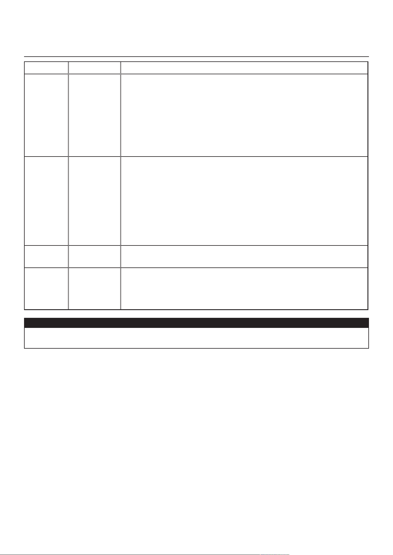
22
a
vertiSSement
d
eSCription
S
olution
W22
Débitd’air
alimentation
ÉTAPE1:Débrancherl’appareil.Effectueruneinspectionvisuelledusystèmedevoletsà
l’alimentation.Nettoyerles�ltres,lesgrillesdedistributionetlabouched’aspirationextérieure.
Véri�erleconduitpours’assurerqu’iln’estpasécraséouplié.Brancherl’appareil.
Sil’ÉTAPE1n’apasrégléleproblème,effectuerl’ÉTAPE2:Enleverleconduitd’alimentation.À
l’écranACL,sélectionnerMAXpourvéri�ersil’appareilestcapabled’atteindreledébitsélectionné.
Sic’estlecas,revoirletrajetduconduit.
Sil’ÉTAPE2n’apasrégléleproblème,effectuerl’ÉTAPE3:Àl’écranACL,sélectionnerles
valeursderéglagedesdébitsMINetMAXetréinitialiserl’appareil.LavaleurdedébitMAX
s’af�cheraàl’écranACL.SiledébitMAXestsupérieuraudébitMAXsouhaité,réglerlesdébits
MAXetMIN.
Sil’ÉTAPE3n’apasrégléleproblème,effectuerl’ÉTAPE4:Remplacerleventilateurà
l’alimentation et répéter l’ÉTAPE 3.
Sil’ÉTAPE4n’apasrégléleproblème,effectuerl’ÉTAPE5:Remplacerl’assemblageélectronique.
W32
Débitd’air
évacuation
ÉTAPE1:Débrancherl’appareil.Effectueruneinspectionvisuelledusystèmedevoletsà
l’évacuation.Nettoyerles�ltres,lesgrillesdedistributionetlabouched’évacuationextérieure.
S’assurer qu’il n’y a pas de volet anti-retour dans la bouche d’évacuation puisqu’il peut geler en hiver.
Véri�erleconduitpours’assurerqu’iln’estpasécraséouplié.Brancherl’appareil.
Sil’ÉTAPE1n’apasrégléleproblème,effectuerl’ÉTAPE2:Enleverleconduitd’alimentation.À
l’écranACL,sélectionnerMAXpourvéri�ersil’appareilestcapabled’atteindreledébitsélectionné.
Sic’estlecas,revoirletrajetduconduit.
Sil’ÉTAPE2n’apasrégléleproblème,effectuerl’ÉTAPE3:Àl’écranACL,sélectionnerles
valeursderéglagedesdébitsMINetMAXetréinitialiserl’appareil.LavaleurdedébitMAX
s’af�cheraàl’écranACL.SiledébitMAXestsupérieuraudébitMAXsouhaité,réglerlesdébits
MAXetMIN.
Sil’ÉTAPE3n’apasrégléleproblème,effectuerl’ÉTAPE4:Remplacerleventilateurà
l’évacuation et répéter l’ÉTAPE 3.
Sil’ÉTAPE4n’apasrégléleproblème,effectuerl’ÉTAPE5:Remplacerl’assemblageélectronique.
W52
Con�guration
initiale
incomplète
ÉTAPE 1 : Appuyer sur + ou - pour accéder au menu sélection.
ÉTAPE2:Compléterlacon�guration.(Consulterlasection5pourobtenirplusdedétails).
W61
Mode protection
surchauffe de
l’électronique
L’appareil est actuellement en mode protection. La puissance transmise au moteur est
volontairement réduite en vue d’abaisser la température de l’électronique. L’appareil
sortiraparlui-mêmedecemodedèsquelesconditionsserontredevenuesnormales.Ilest
donc normal d’observer une diminution des débits durant cette période. Cette condition
devrait se produire uniquement lorsque l’appareil est réglé à haute vitesse et situé dans un
environnement chaud, par exemple plus de 30 °C (86 °F).
8. DÉPANNAGE POUR INSTALLATEUR (
Suite
)
ATTENTION
S’assurer qu’aucun morceau de laine minérale n’entre dans l’appareil durant l’installation. Sinon, cela pourrait
réduire le débit et générer des vibrations et du bruit dans l’appareil.
NOTE:Lesmodèles210et230pi
3
/min ont un ventilateur de refroidissement dans le boîtier électrique qui peut démarrer
silatempératureprèsdel’appareildépasse40°C(104°F).
8.1 p
roTecTion
élecTronique
pour
éviTer
une
pression
sTATique
AnormAlemenT
élevée
ModèlesVRE180pi
3
/min
L’appareil réduira le débit d’air de 30 pi
3
/min si le débit d’air maximum lors de la procédure d’auto-balancement est de
130 pi
3
/minoumoinspouréviterquelamembranedunoyauVREsedéformeàcausedelapressionstatiquetrèsélevée
(plus de 1,3 po d’eau).
Touslesmodèles180pi
3
/min
LeserreursE22ouE32s’af�cherontsiledébitd’airmaximumestde90pi
3
/min ou moins lors de la procédure d’auto-
balancement(l’appareiltenterad’exécuterlaprocédured’auto-balancementà3reprisesavantd’af�cheruneerreur).La
pression statique dans le conduit doit être réduite pour permettre le bon fonctionnement de l’appareil.
ModèlesVRE210pi
3
/min
L’appareil réduira le débit d’air de 30 pi
3
/min si le débit d’air maximum lors de la procédure d’auto-balancement est de
160 pi
3
/minoumoinspouréviterquelamembranedunoyauVREsedéformeàcausedelapressionstatiquetrèsélevée
(plus de 1,3 po d’eau).
Touslesmodèles210et230pi
3
/min
LeserreursE22ouE32s’af�cherontsiledébitd’airmaximumestde120pi
3
/min ou moins lors de la procédure d’auto-
balancement(l’appareiltenterad’exécuterlaprocédured’auto-balancementà3reprisesavantd’af�cheruneerreur).La
pression statique dans le conduit doit être réduite pour permettre le bon fonctionnement de l’appareil.
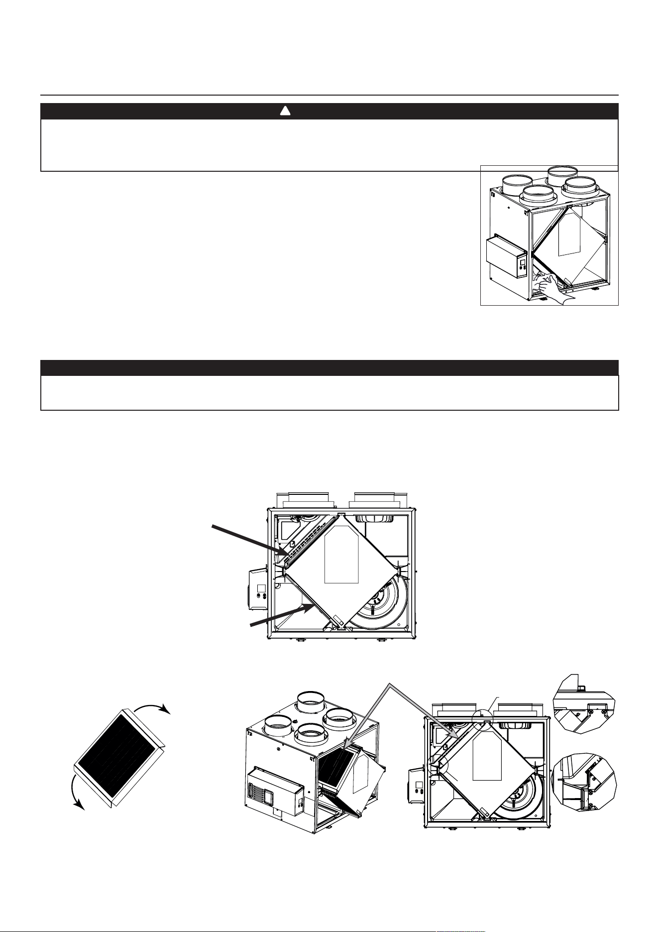
23
9.ENTRETIEN
Risquedehautetension.Lorsdel’entretienoudelaréparation,toujoursarrêterl’appareil,puisledébrancher
pour éviter tout risque de choc électrique. Le port de lunettes et de gants de sécurité est recommandé lors
de la manipulation des composantes de l’appareil pour éviter tout risque de blessure qui pourrait être causée
par la présence de métal mince.
1. Débrancher l’appareil.
2.Laportedel’appareilestmuniedecharnièresetestmaintenueferméepardeuxloquets.Les
ouvrir et mettre la porte de côté.
3. Nettoyer l’intérieur de la porte à l’aide d’un chiffon humide.
4.Nettoyerles�ltres:
• Retirerles�ltres.
• Retirerlapoussièreàl’aided’unaspirateur.
• Laverdansunesolutiond’eauchaudeetdesavondoux.Del’eaudeJavelpeutêtreajoutéesi
désirépourdésinfecter(unecuilleréeàtablepargallon).Rinceràfond.Secouerles�ltrespour
retirerl’excèsd’eauetlaissersécher.
Note:Le�ltreoptionnelestun�ltrejetable.Ildoitêtreremplacélorsqu’ilesttropsale.
5. Retirer le noyau.
6. Nettoyer le bac à condensation à l’aide d’un linge humide.
7.Véri�erlabouched’aspirationextérieure:
• S’assurer qu’il n’y a pas de feuilles, de brindilles, de glace ou de neige qui pourraient être aspirées par la bouche d’air.
• Nettoyer au besoin.
8.Fairetournerlesrouesdesmoteursmanuellement.Sil’uned’entreellestournedif�cilement,contactervotreinstallateur.
9.Remettrelescomposantesenplace.Accorderuneattentionparticulièreàcequeles�ltressoientcorrectementengagésdansleursfentes.
10. Fermer la porte et rebrancher l’appareil.
11. Réinitialiser les �ltres, si requis. Si une commande murale principale optionnelle est utilisée (d
ésHumidisTAT
ou
A
uTomATique
),
appuyersurleboutonINT/AUTOdurant5secondespourréinitialiserles�ltres.Silacommandemuraleprincipaleoptionnelle
Avancée est utilisée, suivre les instructions à l’écran tactile.
ATTENTION
Uneprised’airouun�ltrebouché,mêmepartiellement,pourraitentraînerunmauvaisfonctionnementde
l’appareil. Le confort que procure l’appareil pourrait être réduit et le risque de gel de l’appareil pourrait
augmenter. Un bris d’appareil et/ou des dommages à la propriété pourraient en résulter.
VD0493
9.1 T
rimesTriel
AVERTISSEMENT
!
f
ilTre
merv8
inclus
f
ilTre
opTionnel
(
filTre
à
l
’
évAcuATion
non
inclus
)
f
ilTre
à
l
’
évAcuATion
inclus
NOTE: Le�ltreoptionnelremplacele�ltreMERV8.
Tirer le noyau de 3
po à 4
po vers l’extérieur.
Plierlesdeuxrabatsdu�ltrepourformer
un angle de 45 degrés, tel qu’illustré ci-
dessous.
Installerle�ltresurlenoyau,telqu’illustré
ci-contre.
Pousser le noyau et le �ltre au fond de
l’appareil.
SEE DETAIL A
SEE DETAIL B
DETAIL A
DETAIL B
45˚
45˚
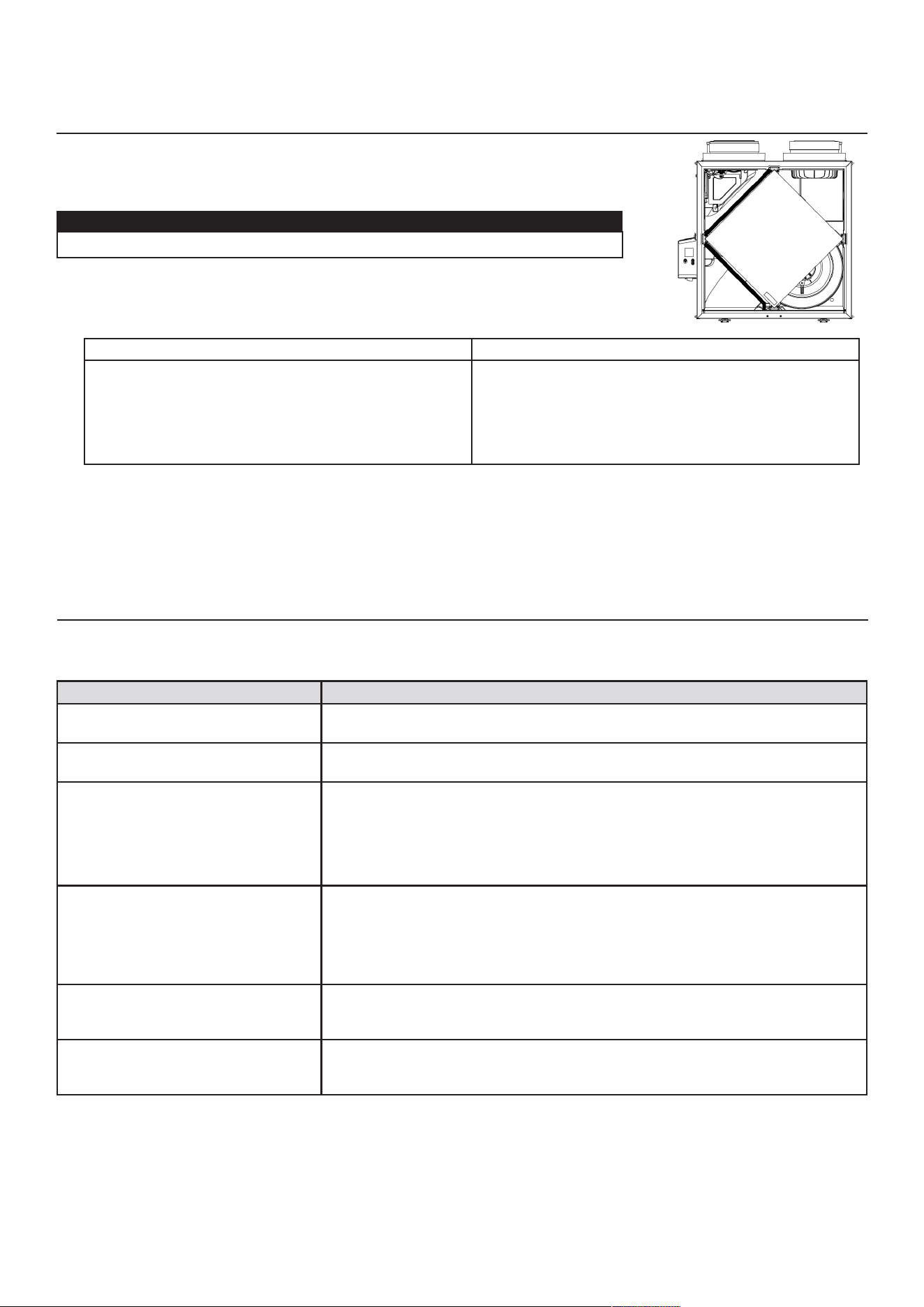
24
1. Répéter les étapes 1 à 6 de la section précédente et effectuer les étapes suivantes:
2. Nettoyer le noyau de récupération:
m
odèles
vrc m
odèles
vre
• Retirer le noyau.
• Le laisser tremper dans un mélange d’eau froide ou
tièdeadditionnéedesavonàvaisselle.
• Rincer abondamment.
• Secouer le noyau pour retirerl’excès d’eau, puis le
laisser sécher.
Enleverlapoussièreàl’aided’unaspirateurmunid’une
brosse à poils doux.
ATTENTION: NE PAS FAIRE TREMPER LE NOYAU DE
RÉCUPÉRATION D’ÉNERGIE
3. Nettoyer les assemblages du ventilateur. Ne pas désassembler les assemblages du ventilateur.
4. Enleverlapoussièreàl’aided’unaspirateurmunid’unebrosseàpoilsdoux.
5. Remettre les composantes en place.
6. Rebrancher l’appareil.
ATTENTION
• Manipuler le noyau de récupération avec soin.
p
roblème
e
SSayer
CeCi
1. Rien ne fonctionne. •Véri�ersil’appareilestbranché.
•Véri�erledisjoncteuroulefusibledelamaisonalimentantl’appareil.
2. L’appareil est bruyant. •Nettoyerl’appareil(voirlasection9).Sileproblèmepersiste,contactervotre
installateur.
3. Condensation à l’intérieur des
fenêtres dans des conditions
climatiques froides.
•Fairefonctionnerl’appareil à vitesse MAX au cours d’activités produisant un
excèsd’humidité(rassemblementsfamiliaux,préparationdeplatscuisinés,etc.).
• Laisser les rideaux entrouverts pour laisser circuler l’air.
•Entreposer le bois de chauffage dans une pièce fermée dotée d’un
déshumidi�cateuroudansunepiècebienaéréeoul’entreposeràl’extérieur.
• Garder la température à l’intérieur de votre maison au-dessus de 18 °C
(
64°F).
4. Humidité à l’intérieur dans des
conditions climatiques chaudes/
humides.
• Faire fonctionner l’appareil à vitesse MIN.
• Utiliser temporairement le mode INT (si disponible).
•Utiliserundéshumidi�cateur.
5. Air trop sec. • Faire fonctionner l’appareil à vitesse MIN.
• Utiliser temporairement le mode INT (si disponible).
•Utilisertemporairementunhumidi�cateur.
6. Air trop froid à la grille de
distribution.
• S’assurer que les bouches extérieures ne sont pas obstruées.
• Faire fonctionner l’appareil à vitesse MIN.
• Installer un chauffage d’appoint (contacter votre installateur).
9.2 A
nnuel
(
à
l
’
AuTomne
)
10.DÉPANNAGEPOURL’UTILISATEUR
Si l’appareil ne fonctionne pas correctement, le réinitialiser comme suit : débrancher l’appareil, attendre durant une minute
puislerebrancher.Pourtoutproblèmenonrésolu,communiqueravecleserviceàlaclientèleau1800567-3855.
VD0494
9.ENTRETIEN(
Suite
)

25
11. GARANTIE
Votre appareil de ventilation est un produit de grande qualité, fabriqué et emballé avec soin. Le fabricant garantit au
consommateur, acheteur initial de ses produits, que ceux-ci sont exempts de tout défaut de fabrication pour la période
citéeplusbasetce,àpartirdeladated’achatoriginale.Lagarantiedetouslesappareilscouvrelespiècesseulement
contre toute défectuosité pouvant nuire à leur fonctionnement, et elle est d’une durée de cinq (5) ans. Sous réserve d’avoir
effectuél’entretiendunoyautelqu’ilestmentionnédansleprésentguide,lenoyauderécupérationdechaleurpossède
une garantie de dix (10) ans, et le noyau de récupération d’énergie est couvert par une garantie de cinq (5) ans. Si un
fonctionnementinadéquatdevaitseproduire,veuillezvousréférerauprésentguide.Sileproblèmepersiste,lamarcheà
suivre est la suivante :
mArcHe à suivre
Si l’appareil est défectueux, veuillez communiquer immédiatement avec votre entrepreneur en ventilation (voir son adresse
sur la page couverture de votre guide de l’utilisateur). Il déterminera la source du mauvais fonctionnement et effectuera le
remplacementoularéparation,s’ilyalieu.Sijamaisildevenaitimpossibledelejoindre,téléphonez(enAmériqueduNord)
au 1 800 567-3855 où notre personnel se fera un plaisir de vous transmettre le numéro de téléphone du distributeur ou du
centredeserviceleplusprèsdechezvous.
pièces de remplAcemenT eT service
Pour assurer le bon fonctionnement de votre appareil, vous devez toujours utiliser des pièces d’origine provenant du
fabricant.Lespiècesd’originedufabricantsontspécialementconçuespoursatisfairetouteslesnormesdecerti�cationde
sécuritéapplicables.Leurremplacementpardespiècesneprovenantpasdufabricantpourraitnepasassurerlasécurité
del’appareil,entraîneruneréductionsévèredesperformancesainsiqu’unrisquededéfaillanceprématurée.Lefabricant
recommandeégalementdetoujoursvousréféreràuneentreprisedeservicescompétenteetreconnueparlefabricantpour
vospiècesderemplacementetappeldeservice.
fAcTure
Aucune réparation ou aucun remplacement ne sera couvert par la garantie sans la copie de la facture originale d’achat.
Prenez soin de bien la conserver.
frAis divers
Lesfraisdemain-d’œuvrerelatifsauretraitdelapiècedéfectueuseet/ouàl’installationdelapièceconformeneseront,en
aucun cas, couverts par le fabricant.
condiTions eT limiTes
Vise un bâtiment pour lequel la partie 9 de la division B de la version en vigueur du Code national du bâtiment du Canada
s’applique avec les restrictions et exception additionnelles indiquées ci-dessous:
Domaine d’application de la partie 9, division B selon la version en vigueur du Code national du bâtiment du Canada :
Lapartie9deladivisionBs’appliquepourtoutbâtimentviséparlesdé�nitionsetconditionsdelaversionenvigueurdu
Code national du bâtiment du Canada indiquées ci-dessous:
Tout bâtiment* d’une hauteur de bâtiment d’au plus 3 étages, d’une aire de bâtiment d’au plus 600 m2, et qui abritent des
usages principaux du :
Groupe C1, habitations,
Groupe D2, établissement d’affaires,
Groupe E3, établissements commerciaux, ou
Groupe F, divisions 2
4
et 3
5
, établissements industriels à risques moyens et établissements industriels à risques faibles.
Et tout bâtiment dont l’usage principal est classé comme suit :
Groupe C1
,
habitations avec aire de bâtiment de plus de 600 m
2
ou d’une hauteur de bâtiment de plus de 3 étages.
Cependant, les établissements du groupe F sont exclus puisque les VRE/C ont seulement été évalués pour une installation
dans des endroits sans risques conformément à la norme de sécurité canadienne applicable.
Se référer au tableau ci-dessous pour obtenir des exemples communs compris dans chaque groupe d’établissements.
Groupe & Division Usage principal Exemples
C Habitations Maisons unifamiliales, Auberges,
Bâtiments multifamiliaux
D Établissement d’affaires Banques, Bureaux
E Établissement commercial Grands magasins, Supermarchés
Se référer à la note A-3.1.2.1 de la version en vigueur du Code national du bâtiment du Canada pour obtenir plus d’exemples.
*La détermination de la taille d’un bâtiment prend en considération la séparation intérieure et doit être évaluée conformément
à la section 1.3.3.4 du Code national du bâtiment du Canada en vigueur.

26
1
Habitation : bâtiment, ou partie de bâtiment, où des personnes peuvent dormir, sans y être hébergées en vue de recevoir
des soins ou des traitements, et sans y être détenues.
2
Établissement d’affaires (Groupe D) : bâtiment, ou partie de bâtiment, utilisé pour la conduite des affaires ou la prestation
de services professionnels ou personnels.
3
Établissement commercial (Groupe E) : bâtiment, ou partie de bâtiment, utilisé pour l’étalage ou la vente de marchandises
ou de denrées au détail.
4
Établissement industriel à risques moyens (Groupe F, Division 2) : établissement industriel non classé comme établissement
industriel à risques très élevés, mais dont le contenu combustible par aire de plancher est supérieur à 50 kg/m
2
ou
1200 MJ/m
2
.
5
Établissement industriel à risques faibles (Groupe F, Division 3) : établissement industriel dont le contenu combustible par
aire de plancher est d’au plus 50 kg/m
2
ou 1200 MJ/m
2
.
Exception :
L’installation dansune salle de classeest acceptableàcondition quel’unitésoit installéeavecunsystèmede conduits
indépendant, distinct du systèmeCVAC, qui est limité à cettesalle de classe et servant à ventiler cettesalle declasse
seulement. Les restrictions supplémentaires de cette section demeurent applicables.
Restrictions :
Le VRC/E ne doit pas être installé dans un environnement ni être utilisé pour évacuer de l’air contenant:
- Gaz, vapeur, émanations ou solvants corrosifs.
-Gaz,vapeur,émanations,solvantsoupoussièresinammablesouexplosifs.
- Concentrations élevées de parfums, de vernis à ongles ou de produits de traitement capillaire (agents de
décoloration et de coloration, etc) tel qu’on les trouve dans les salons de coiffure ou les salons de manucure.
- Concentration élevée d’émanations chimiques provenant de solvants, de peinture ou d’agents de nettoyage.
Le VRC/E ne doit pas être utilisé pour évacuer l’air dépassant 50 % HR et un point de rosée de 11
o
C sur une longue période
(plus de 24 heures) lorsque la température extérieure est sous -15
o
C.
Le VRC/E ne doit pas être utilisé pour évacuer l’air d’un environnement contenant une concentration élevée de particules à
moinsquel’airévacuésoitpré-�ltréàl’aidede�ltreshauteef�cacitésélectionnésselonlatailledesparticulesavantleur
entrée dans le VRC/E.
Le VRC/E ne doit pas être utilisé pour évacuer les émanations de cuisson, mais peut être utilisé pour ventiler la cuisine
dans un bâtiment du groupe C d’une hauteur de bâtiment d’au plus 3 étages et d’une aire de bâtiment d’au plus 600 m
2
seulement. L’emplacement du registre d’évacuation d’air vicié doit respecter les exigences du Code du bâtiment et du guide
d’installation et d’utilisation.
Lesapplicationsmettantencausedespathogènesouvirusaériens,delafuméeoudesgaznocifsnesontpasrecommandées.
De telles applications nécessitent une attention supplémentaire pour éviter la recirculation et la contamination croisée
interne.Veuillezcontacterleserviceàlaclientèlepourplusd’information.
La garantie ci-dessus s’appliquera dans tous les cas où les dommages ne seront pas le résultat d’une installation inadéquate,
d’un usage inapproprié, d’abus ou de négligence, de cas fortuit ou de toute autre circonstance hors du contrôle du fabricant.
Deplus,lefabricantneserapastenuresponsabledesblessuresoudommagesàlapropriétépersonnelleouimmobilière
causés directement ou indirectement par l’appareil de ventilation. Cette garantie annule toutes les garanties précédentes.
Venmar Ventilation ULC, 550 boul. Lemire, Drummondville, Québec, Canada J2C 7W9 venmar.ca / vanee.ca 800 567-3855