READ AND SAVE THESE INSTRUCTIONS!
Always disconnect the unit before making any connections. Failure in disconnecting power could result in electric
shock or damage of the wall control or electronic module inside the unit.
WARNING
!
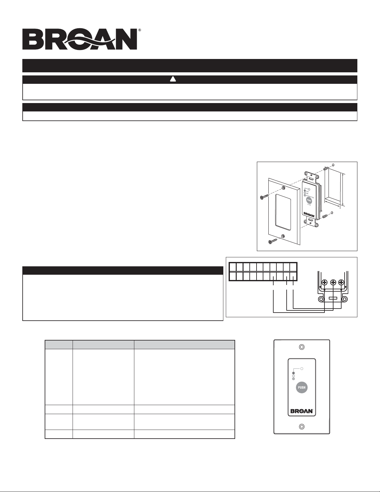
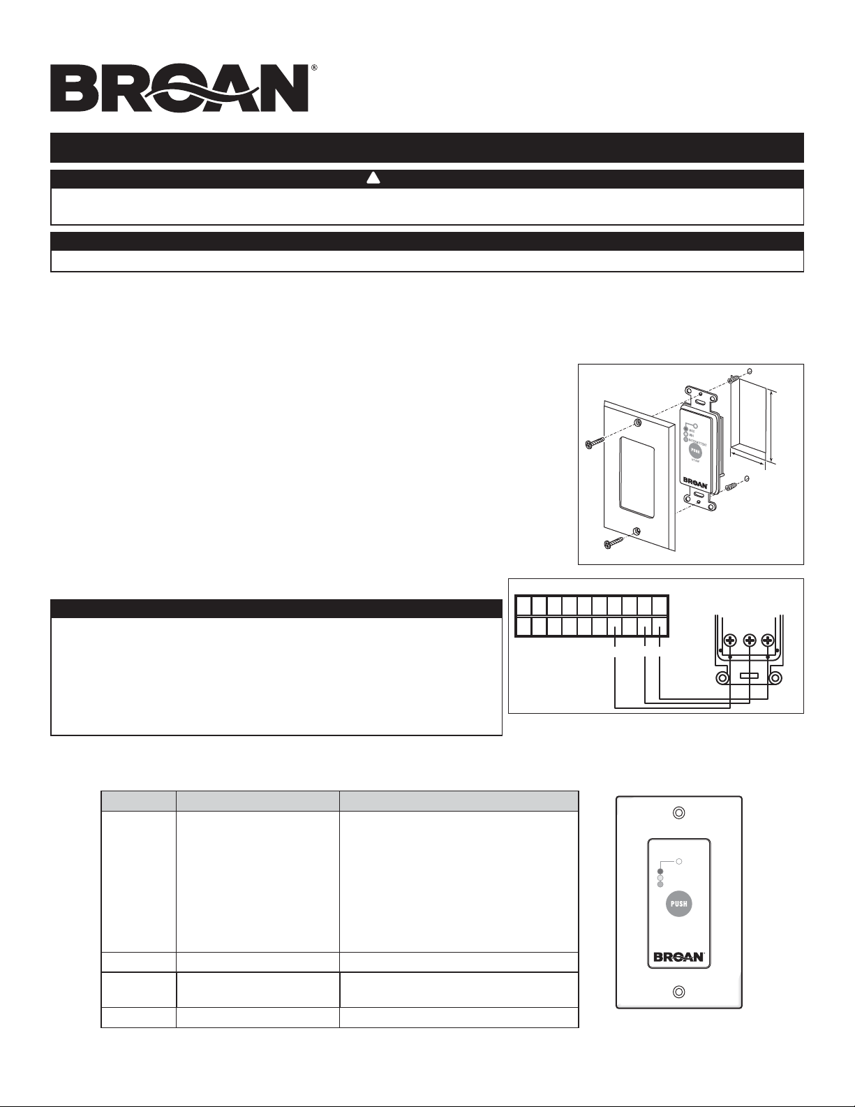
Cut a 2³/8” x 1³/8” hole in a wall, at a convenient location for the wall control. Route the wall
control cable from the unit to this hole. See figure at right.
Temporarily place the switch over the hole and mark both mounting screw hole positions.
Remove the push button, drill both screw holes (3/16” Ø) in wall and insert both wall anchors.
1 3/8”
2 3/8”
VC0121
Mount the VT4W wall control to the wall. Plug the ventilation unit and test the wall control operation.
NO C NC I OC OL Y R G B
B G
G
B
Y
VE0328A
Y
INTERMITTENT
MAX
MIN
VC0070
VT4W
05890E rev. 03
Never install more than one VT4W main wall control per unit.
CAUTION
Make sure the wires do not short-circuit between themselves or
by touching any other components on the wall control. Avoid poor
wiring connections. To reduce internal interference (noise) potential,
do not run wall control wiring next to another control contactors
or near light dimming circuits, electrical motors, dwelling/building
power or lighting wiring, or power distribution panel.
CAUTION
Color Mode Suggested use
GREEN Intermittent Select this mode when you are
away from the house for a few days.
Also, when you deem the inside
air is too dry in cold season or too
humid in cooling season. In this mode, the
unit is OFF for 40 minutes per hour and
ventilates at minimum speed the
remaining 20 minutes of the hour.
YELLOW Min. speed ventilation For normal daily operation.
RED Max. speed ventilation For excess pollutants and humidity
(parties, odors, smoke, etc.)
No light Off To perform maintenance.
NOTES: 1. This wall control will only operate on following Broan units: ERV70S, ERV70T, HRV80S, HRV80T, HRV90S, HRV90T, ERV110T,
ERV110S, HRV120T, HRV120S, ERV120T, ERV120S, ERV140TE, HRV160TE, HRV160T, ERV100S, ERV100SP, HRV150S,
ERV180S and HRV190S.
2. The integrated control on these units must be turned OFF to ensure proper wall control operation.
VT4W
MAIN WALL CONTROL
REAR VIEW
INSTRUCTION SHEET
VT4W WALL CONTROL INSTALLATION
PART NUMBER VT4W
INSTALLATION
Perform the electrical connetion as showm at right.
¡ LEA Y CONSERVE ESTAS INSTRUCCIONES !
Desconecte el aparato siempre antes de efectuar cualquier conexión. De no hacerlo, pódria producirse un choque
eléctrico o daños en el control de pared o en el módulo electrónico que hay dentro del aparato.
ADVERTENCIA
!
Corte en la pared un agujero de 2³/8” de alto x 1³/8” de ancho, en la ubicación más
conveniente para el control de pared. Dirija el cable de control desde la unidad hasta el
control de pared. Véase la ilustración al lado.
Coloque momentáneamente el interruptor en el agujero para marcar la ubicación correcta
de los dos anclajes para pared.
Retire el interruptor, perfore los dos orificios (3/16” Ø) e introduzca los dos anclajes para
pared.
1 3/8”
2 3/8”
VC0121
Instale el control de pared VT4W en la pared. Enchufe el aparato y pruebe el funcionamiento del control de pared.
NO C NC I OC OL Y R G B
B G
V
N
A
VE0328E
Y
INTERMITTENT
MAX
MIN
VC0070
VT4W
05890E rev. 03
No instale nunca más de un control de pared VT4W por aparato.
CUIDADO
Compruebe que los cables no hagan cortocircuito entre ellos o
tocando otros componentes del control de pared. Evite las malas
conexiones de los cables. Para reducir la interferancia eléctrica
(ruido) potencial, no pase los cables del control de pared cerca de
los contactores de control ni de circuitos de atenuación de la luz,
motores eléctricos, alimentación de viviendas o edificios, cables
de iluminación o tableros de distribución de energía.
CUIDADO
Color Modo Uso sugerido
VERDE Intermittente Seleccione este modo cuando no esté
en su casa durante unos días o cuando
considere que el aire interior está
demasiadoseco durante la estación fría, o
demasiado húmedo en la estación cálida.
En este modo el aparato se apaga
durante 40 minutos por hora e intercambia
el aire con el exterior a baja velocidad
durante los últimos 20 minutos de la hora.
AMARILLO Ventilación velocidad Mín. Funcionamiento normal diario.
ROJO Ventilación velocidad Máx. Cuando haya demasiados contaminantes
y humedad (fiestas, olores, humo, etc.).
Sin luz Apagado Para efectuar el mantenimiento.
NOTAS: 1. Este control de pared sólo funcionará con los siguientes aparatos de Broan: ERV70S, ERV70T, HRV80S, HRV80T, HRV90S,
HRV90T, ERV110T, ERV110S, HRV120T, HRV120S, ERV120T, ERV120S, ERV140TE, HRV160TE, HRV160T, ERV100S,
ERV100SP, HRV150S, ERV180S and HRV190S.
2. Debe apagarse el control integrado des los aparatos para que el control de pared funcione debidamente.
VISTA POSTERIOR DEL
CONTROL DE PARED
PRINCIPAL VT4W
HOJA DE INSTRUCCIONES
INSTALACIÓN DEL CONTROL DE PARED VT4W
NÚMERO DE PIEZA VT4W
INSTALACIÓN
Haga la conexión eléctrica como se ve en la ilustración de al lado..
