
March 2015
© 2015 Fluke Corporation. All rights reserved. Specifications are subject to change without notice.
All product names are trademarks of their respective companies.
721Ex
Pressure Calibrator
Users Manual
1.888.610.7664 sales@GlobalTestSupply.com
Fluke-Direct.com

LIMITED WARRANTY AND LIMITATION OF LIABILITY
This Fluke product will be free from defects in material and workmanship for three years from the date of purchase. This
warranty does not cover fuses, disposable batteries, or damage from accident, neglect, misuse, alteration, contamination, or
abnormal conditions of operation or handling. Resellers are not authorized to extend any other warranty on Fluke’s behalf.
To obtain service during the warranty period, contact your nearest Fluke authorized service center to obtain return
authorization information, then send the product to that Service Center with a description of the problem.
THIS WARRANTY IS YOUR ONLY REMEDY. NO OTHER WARRANTIES, SUCH AS FITNESS FOR A PARTICULAR
PURPOSE, ARE EXPRESSED OR IMPLIED. FLUKE IS NOT LIABLE FOR ANY SPECIAL, INDIRECT, INCIDENTAL OR
CONSEQUENTIAL DAMAGES OR LOSSES, ARISING FROM ANY CAUSE OR THEORY. Since some states or countries
do not allow the exclusion or limitation of an implied warranty or of incidental or consequential damages, this limitation of
liability may not apply to you.
11/99
1.888.610.7664 sales@GlobalTestSupply.com
Fluke-Direct.com

i
Table of Contents
Title Page
Introduction .................................................................................................................... 1
Contact Fluke ................................................................................................................. 1
Safety Information .......................................................................................................... 2
Ex-Hazardous Areas ................................................................................................. 4
Measuring Pressure .................................................................................................. 4
Symbols ......................................................................................................................... 5
Standard Equipment....................................................................................................... 6
Product Features ............................................................................................................ 6
Display ....................................................................................................................... 9
Language Selection ................................................................................................... 11
Home Menu Functionality .......................................................................................... 11
Backlight Use ............................................................................................................ 11
Zero Function ............................................................................................................ 11
Menus ........................................................................................................................ 12
SWITCHTEST ........................................................................................................... 12
1.888.610.7664 sales@GlobalTestSupply.com
Fluke-Direct.com

721Ex
Users Manual
ii
%ERROR .................................................................................................................. 15
MINMAX ................................................................................................................... 18
SET UNITS ............................................................................................................... 19
CONTRAST .............................................................................................................. 20
Lock and Unlock Configurations (CFG) .................................................................... 20
AUTO OFF ................................................................................................................ 21
RESOLUTION ........................................................................................................... 22
PROBE TYPE ........................................................................................................... 22
DAMP ....................................................................................................................... 24
Measure Pressure ......................................................................................................... 25
Media Compatibility ....................................................................................................... 25
Measurements ............................................................................................................... 26
Transmitter Calibration .................................................................................................. 27
mA Input Function ..................................................................................................... 27
Pressure-to-Current Transmitter Calibration ............................................................. 27
Ranges and Resolution ............................................................................................. 29
Maintenance .................................................................................................................. 30
Replace the Batteries ................................................................................................ 30
Clean the Product ..................................................................................................... 31
User-Replaceable Parts and Accessories ..................................................................... 32
Specifications ................................................................................................................ 34
Environmental ........................................................................................................... 34
Electrical and Temperature Measurement (1 year) ................................................... 34
Physical .................................................................................................................... 35
1.888.610.7664 sales@GlobalTestSupply.com
Fluke-Direct.com

iii
List of Tables
Table Title Page
1. Symbols ................................................................................................................................. 5
2. Product Features ................................................................................................................... 8
3. Display Functions .................................................................................................................. 10
4. Ranges and Resolutions ....................................................................................................... 29
5. Approved Batteries ................................................................................................................ 30
6. User-Replaceable Parts and Accessories ............................................................................. 32
1.888.610.7664 sales@GlobalTestSupply.com
Fluke-Direct.com

721Ex
Users Manual
iv
1.888.610.7664 sales@GlobalTestSupply.com
Fluke-Direct.com

v
List of Figures
Figure Title Page
1. Product Interface ................................................................................................................... 7
2. Display................................................................................................................................... 10
3. Pressure Switch Connection ................................................................................................. 13
4. Percent Error Function Connection ....................................................................................... 16
5. Temperature Measurement with RTD Probe ......................................................................... 24
6. Measure Current ................................................................................................................... 26
7. Pressure-to-Current Transmitter Connections ....................................................................... 28
8. Battery Replacement ............................................................................................................. 31
9. User-Replaceable Parts and Accessories ............................................................................. 33
1.888.610.7664 sales@GlobalTestSupply.com
Fluke-Direct.com

721Ex
Users Manual
vi
1.888.610.7664 sales@GlobalTestSupply.com
Fluke-Direct.com

1
Introduction
The 721Ex Pressure Calibrator (the Product) is a simple
to use and versatile pressure calibrator. The two internal
pressure sensors are configured with different pressure
measurement ranges. One range for lower pressure (P1)
and one range for higher pressure (P2). The Product
features inputs for mA, switch contacts, and an RTD
probe.
1.888.610.7664 sales@GlobalTestSupply.com
Fluke-Direct.com

721Ex
Users Manual
2
Safety Information
A Warning identifies conditions and procedures that are
dangerous to the user. A Caution identifies conditions
and procedures that can cause damage to the Product or
the equipment under test.
Warning
To prevent possible electrical shock, fire, or
personal injury:
• Only assemble and operate high-pressure
systems if you know the correct safety
procedures. High-pressure liquids and
gases are hazardous and the energy from
them can be released without warning.
• Read all safety information before you use
the Product.
• Carefully read all instructions.
• Only operate the Product in non-hazardous
areas or classified areas where this device
is certified to operate.
• Use the correct terminals, function, and
range for measurements.
• Do not apply more than the rated voltage,
between the terminals or between each
terminal and earth ground.
• Do not touch voltages > 30 V ac rms, 42 V
ac peak, or 60 V dc.
• Remove all probes, test leads, and
accessories before the battery door is
opened.
• Do not exceed the Measurement Category
(CAT) rating of the lowest rated individual
component of a Product, probe, or
accessory.
• Do not use and disable the Product if it is
damaged.
• Remove the input signals before you clean
the Product.
• Use only specified replacement parts.
• Have an approved technician repair the
Product.
• Use the Product only as specified, or the
protection supplied by the Product can be
compromised.
• Only change batteries in an area known to
be non-hazardous.
1.888.610.7664 sales@GlobalTestSupply.com
Fluke-Direct.com

Pressure Calibrator
Safety Information
3
• The battery door must be closed and
locked before you operate the Product.
• Do not improperly apply pressure. Vacuum
should not be applied to any gauge
pressure sensor. The Product display
shows “OL” when an inappropriate
pressure is applied. If “OL” is shown on
any pressure display, the pressure should
be reduced or vented immediately to
prevent Product damage or possible
personnel injury. “OL” is shown when the
pressure exceeds 110 % of the nominal
range of the sensor or when a vacuum in
excess of 2 PSI is applied on gauge range
sensors.
• Push the ZERO button to zero the pressure
sensor when vented to atmospheric
pressure.
• Check entity parameters before making
any connections to this Product.
• Remove the batteries if the Product is not
used for an extended period of time, or if
stored in temperatures that exceed the
battery manufacturer’s specifications. If
the batteries are not removed, battery
leakage can damage the Product.
• Replace the batteries when the low battery
indicator shows to prevent incorrect
measurements.
• Be sure that the battery polarity is correct
to prevent battery leakage.
• Repair the Product before use if the battery
leaks.
• Use only specified replacement parts.
1.888.610.7664 sales@GlobalTestSupply.com
Fluke-Direct.com

721Ex
Users Manual
4
Ex-Hazardous Areas
An Ex-hazardous area as used in this manual refers to an
area made hazardous by the potential presence of
flammable or explosive vapors. These areas are also
referred to as hazardous locations.
The Product has been designed for use in Ex-Hazardous
Areas. These are areas where potentially flammable or
explosive vapors may occur. These areas are referred to
as hazardous (classified) locations in the United States,
as Hazardous Locations in Canada, as Potentially
Explosive Atmospheres in Europe and as Explosive Gas
Atmospheres by most of the rest of the world. The
Product is designed as intrinsically safe. This means that
connecting the Product to equipment that is used within
intrinsically-safe circuits will not cause an ignition-capable
arc as long as the entity parameters are suitably
matched.
Warning
To prevent possible personal injury, check
entity parameters before making any
connections to this device.
Measuring Pressure
Warning
For safe operation and maintenance of the
Product, Refer to the table of ranges and
resolutions at the back of the manual for
information about overpressure and burst
pressure ratings. Pressure sensors can be
damaged and personnel injury can occur due
to improper application of pressure. Vacuum
should not be applied to any gauge pressure
sensor. The Product display shows “OL”
when an inappropriate pressure is applied. If
“OL” is seen on any pressure display, reduce
or vent pressure immediately to prevent
equipment damage or possible personnel
injury. “OL” is shown when pressure >120 %
of the nominal range of the sensor or when a
vacuum >2 PSI is applied on gauge range
sensors.
1.888.610.7664 sales@GlobalTestSupply.com
Fluke-Direct.com

Pressure Calibrator
Symbols
5
Symbols
Symbols used on the Product or in this manual are shown in Table 1.
Table 1. Symbols
Symbol Description Symbol Description
Risk of Danger. Important information. See
Manual.
Conforms to relevant Australian EMC standards.
Hazardous voltage. Risk of electric shock.
Battery
Conforms to European Union directives.
Conforms to relevant South Korean EMC Standards.
Conforms to ATEX requirements
This product complies with the WEEE Directive
(2002/96/EC) marking requirements. The affixed label
indicates that you must not discard this
electrical/electronic product in domestic household
waste. Product Category: With reference to the
equipment types in the WEEE Directive Annex I, this
product is classed as category 9 "Monitoring and
Control Instrumentation" product. Do not dispose of
this product as unsorted municipal waste. Go to
Fluke’s website for recycling information.
1.888.610.7664 sales@GlobalTestSupply.com
Fluke-Direct.com

721Ex
Users Manual
6
Standard Equipment
Make sure that the Product shipment is complete. It must
include:
• The Product
• Product Manuals CD
• Getting Started Manual
• Quick Reference Guide
• Test leads
• Carry case
• Calibration certificate
Product Features
Figure 1 and Table 2 shows the location of the buttons,
pressure controls, connection ports, and electrical inputs.
1.888.610.7664 sales@GlobalTestSupply.com
Fluke-Direct.com

Pressure Calibrator
Product Features
7
F1 F2 F3
ZERO
1
2
3
4
5
6
8
7
9
10
11
hvf001.eps
Figure 1. Product Interface
1.888.610.7664 sales@GlobalTestSupply.com
Fluke-Direct.com

721Ex
Users Manual
8
Table 2. Product Features
Item Description
Power button. Turns on and off the Product
Function buttons. Used to configure the Product. These keys correspond to messages on the display.
Zero button. Zeros pressure measurements.
Backlight button. Push to turn the backlight on or off.
COMMON input
Input terminals to measure current and a contact closer for switch test.
Low pressure port [P1]
High pressure port [P2]
RTD probe connector
Firmware programming connector (for factory use only)
Battery door
1.888.610.7664 sales@GlobalTestSupply.com
Fluke-Direct.com

Pressure Calibrator
Product Features
9
Notes
When is pushed to turn on the Product, a
short startup self-check routine is run. During
that routine, the display shows the current
firmware revision level, auto-shutdown status,
and the range of the internal pressure sensors.
A maximum of 5 minutes warm-up is necessary
for the product to reach rated accuracy. A longer
warm-up period can be necessary for large
changes in ambient temperature. See the “Zero
Function Use” section for more about zeroing
the pressure sensor displays. It is recommended
that pressure ranges be zeroed each time the
Product is started.
Display
The display has two main regions:
• The menu bar (located at the bottom of the screen) is
used with the function buttons to access the Product
menu.
• The main display has a maximum of three process
measurement sub-regions.
These sub-regions will be referred to as the UPPER,
MIDDLE and LOWER displays. Figure 2 shows the
location of the different display fields. Table 3 describes
them.
1.888.610.7664 sales@GlobalTestSupply.com
Fluke-Direct.com

721Ex
Users Manual
10
hvf007.eps
Figure 2. Display
Table 3. Display Functions
Item
Number
Nam
e Description
Primary
Parameters
Shows what is being
measured.
Span
Indicator
Shows the percent of the
4 mA to 20 mA span. (For
mA functions only.)
Pressure
Units
Shows one of 17 pressure
units available for display.
Units
Shows the unit of measure
for the display.
1.888.610.7664 sales@GlobalTestSupply.com
Fluke-Direct.com

Pressure Calibrator
Product Features
11
Language Selection
The user interface is available in three languages:
• English
• Norwegian
• German
To select a language:
1. Turn the Product off.
2. Hold down , , and simultaneously.
3. As the Product powers up, the display shows the
language in the top left corner of the display. Repeat
the procedure to show each subsequent language.
Once the necessary language is shown, the Product
user interface stays in that language until another
language is chosen.
Home Menu Functionality
There are three options for the Home Menu:
• P1/P2
• mA/RTD
• MENU
These options are shown across the bottom of the
display.
From anywhere within the menu structure, push to get
back to the Home Menu.
Backlight Use
Push to toggle on and off the backlight.
Zero Function
In pressure mode and when the pressure is within the
zero limit, The Product zeros pressure on any port that is
currently shown on the display. The zero limits are within
10 % of the full-scale range of the selected sensor. If the
display shows “OL,” the zero function will not operate.
1.888.610.7664 sales@GlobalTestSupply.com
Fluke-Direct.com

721Ex
Users Manual
12
Menus
There are 11 sub menus that can be accessed from
(Main Menu). Push to go to the next menu selection.
For the last menu, push (DONE) to return to the Main
Menu.
The 11 sub-main menus are:
• SWITCHTEST
• %ERROR
• MINMAX
• SET UNITS
• CONTRAST
• LOCK CFG
• AUTO OFF
• RESOLUTION
• HART
• PROBE TYPE
• DAMP
Push , , or , depending on the menu, to toggle
through each parameter of an active menu. The individual
menus are explained in the subsequent sections.
SWITCHTEST
To access the SWITCHTEST menu, push .
SWITCHTEST is shown on the menu bar.
Connect a pressure switch to the Product as shown in
Figure 3.
For all connections in this manual:
Warning
To prevent possible electrical shock, fire, or
personal injury, check entity parameters
before making any connections to this
Product.
1.888.610.7664 sales@GlobalTestSupply.com
Fluke-Direct.com

Pressure Calibrator
Product Features
13
F1 F2 F3
ZERO
Pressure
Switch
Use low volume tubing
when possible
hvf017.eps
Figure 3. Pressure Switch Connection
To do a switch test:
1. Use the P1 or P2 pressure input connections to
connect the Product to the input of the switch.
Connect the contact output of the switch to the COM
and mA terminals of the Product. The polarity of the
terminals does not matter.
2. Connect the pump to the Product and the pressure
switch.
3. Make sure the vent on the pump is open.
4. Push to select P1 or P2 depending on how the
Product is connected.
5. Zero the Product if necessary.
6. Close the vent after the Product is zeroed.
7. If connected to a normally closed switch, the top of
the display will read “CLOSE”.
8. Slowly apply pressure with the pump until the switch
opens.
Note
In the SWITCHTEST mode the display update
rate is increased to help capture changing
pressure inputs. Even with this enhanced
sample rate pressurizing, the test should be
done slowly to ensure accurate readings.
1.888.610.7664 sales@GlobalTestSupply.com
Fluke-Direct.com

721Ex
Users Manual
14
9. Once the switch is open, “OPEN” will be shown.
Bleed the pump slowly until the pressure switch
closes.
hix043.eps
At the top of the display it will now read, “SW OPENED
AT” and show the pressure at which the switch opened.
hix044.eps
1.888.610.7664 sales@GlobalTestSupply.com
Fluke-Direct.com

Pressure Calibrator
Product Features
15
10. Push the “NEXT” option to view when the switch
closed, and the dead band.
hix045.eps
hix046.eps
11. Push the “NEW TEST” option to clear the data and
do another test.
12. Push to en
d the test and return to the main menu.
%ERROR
The Product features a unique function which can
calculate pressure vs. milliamp error as a percentage of
the 4 mA - 20 mA loop span. The %ERROR mode uses
all three screens and has a unique menu structure. It
simultaneously shows pressure, mA, and percent error.
See Figure 4.
1.888.610.7664 sales@GlobalTestSupply.com
Fluke-Direct.com

721Ex
Users Manual
16
F1 F2 F3
ZERO
-
External
Loop Supply
hvf019.eps
Figure 4. Percent Error Function Connection
1.888.610.7664 sales@GlobalTestSupply.com
Fluke-Direct.com

Pressure Calibrator
Product Features
17
Example:
A pressure transmitter under test is 30 psi (2 Bar) Full-
Scale and outputs a corresponding 4 mA to 20 mA signal.
Program a 0 psi to 30 psi pressure span into the Product
and the Product calculates and shows the deviation or
%Error from the expected 4 mA to 20 mA output. This
eliminates the need for manual calculations and helps
when it is difficult to set an exact pressure.
To use the %ERROR function:
1. Push to access the menus.
2. Push to step through the menu until %ERROR is
shown on the menu bar.
3. Push to open the %ERROR screen.
4. Push to scroll through the port choices (P1 or P2).
5. Push to configure the pressure range settings.
6. Use the arrow keys to set the 100 % point of the
desired pressure range, select DONE SET when
finished.
7. Use the arrow keys to set 0 % point and select
DONE SET. The % ERROR mode is now ready to
use.
Note
The 0 % and 100 % point will be saved in non-
volatile memory until they are changed again by
the user.
hmq054.eps
1.888.610.7664 sales@GlobalTestSupply.com
Fluke-Direct.com
721Ex
Users Manual
18
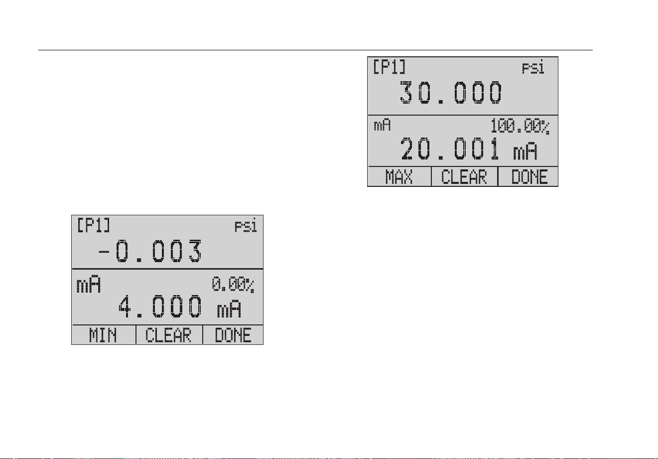
MINMAX
The Product has a min/max feature to capture the
minimum and maximum values of any displayed
parameter. To use the MINMAX menu:
1. Push to access the menus.
2. Push to step through the menu until MINMAX is
shown on the menu bar.
3. Push to toggle the display through the min and
max values that are stored in the min/max registers.
These readings are live so that the new min/max
values will be recorded while in this mode.
hix055.eps
hix056.eps
To reset the min/max registers, push for “CLEAR”.
These registers are also cleared at power-up or when the
configuration is changed. Push to exit MIN MAX and
see live measurements.
1.888.610.7664 sales@GlobalTestSupply.com
Fluke-Direct.com

Pressure Calibrator
Product Features
19
SET UNITS
Use the SET UNITS menu to select the measurement
units for each port. To use this menu:
1. Push to access the menus.
2. Push to step through the menu until SET UNITS is
shown on the menu bar.
3. Push to select the necessary unit. The choices
are:
• inHg 0 °C
• mmHg 0 °C
• kg/cm
2
• mmH
2
O 4 °C
• mmH
2
O 20 °C
• ftH
2
O 60 °F
• psi
• inH
2
O 4 °C
• inH
2
O 20 °C
• inH
2
O 60 °F
• cmH
2
O 4 °C
• cmH
2
O 20 °C
• bar
• mbar
• MPa
• kPa
1.888.610.7664 sales@GlobalTestSupply.com
Fluke-Direct.com

721Ex
Users Manual
20
4. Push to move through each function (P1, P2, or
RTD) and change to the desired units.
5. Push when finished with units selection.
CONTRAST
Use the Contrast menu to adjust the display contrast.
1. Push to access the menus.
2. Push to step through the menu until CONTRAST
is shown on the menu bar.
3. Push to access the Contrast menu.
hix024.eps
4. Push and repeatedly to adjust the display
contrast to the necessary level. Push to finish the
adjustment and go home as shown below.
hix025.eps
Lock and Unlock Configurations (CFG)
Use the LOCK CFG or UNLOCK CFG options of the
Configuration Lock Menu (CONFIG), shown below, to
lock or unlock the display configuration.
hix026.eps
When the LOCK CFG option is pushed, the menu display
goes home and the menu configuration option on the
Main Menu is locked. All menus are locked with the
exception of:
• MINMAX
• CONTRAST
• CONFIG
1.888.610.7664 sales@GlobalTestSupply.com
Fluke-Direct.com

Pressure Calibrator
Product Features
21
You will also notice that some menu choices disappear
when the LOCK CFG is used.
When the UNLOCK CFG option is selected, the
configuration is unlocked and the menu display goes to
the subsequent menu.
AUTO OFF
The Product can be set to automatically power off after a
chosen number of minutes. This function can also be
disabled. To set the auto off parameters:
1. Push to access the menus.
2. Push to step through the menu until AUTO OFF is
shown on the menu bar.
3. Push on the Auto Off Main Menu shown below.
hix031.eps
4. Push or to select the number of minutes before
the Product turns off or scroll down to 0 to disable
Auto Off as shown below.
hix032.eps
5. Push to set the parameters and go to the main
menu. The auto off time is reset when a key is
pushed.
1.888.610.7664 sales@GlobalTestSupply.com
Fluke-Direct.com

721Ex
Users Manual
22
RESOLUTION
To choose between a low or high resolution display:
1. Push to access the menus.
2. Push to step through the menu until
RESOLUTION is shown on the menu bar.
3. Push to select the Resolution menu.
4. Push or to turn low resolution on or off.
5. Push when finished.
hmq062.eps
PROBE TYPE
To select an external RTD probe for use with the Product:
1. Push to access the menus.
2. Push to step through the menu until PROBE is
shown on the menu bar.
hix035.eps
3. Push on to select the Probe type. The probe
choices are:
• P100-385
• P100-392
• P100-JIS
1.888.610.7664 sales@GlobalTestSupply.com
Fluke-Direct.com

Pressure Calibrator
Product Features
23
4. Push to select the necessary probe type (see the
figure below). Push to store the change and go to
the Main Menu.
Note
The default probe type is PT100-385.
SELECT RTD PROBE TYPE
hix036.eps
5. Connect the RTD Probe.
The standard probe has a 10-inch insertion depth with a
¼-inch diameter stainless steel sheath. See Figure 5.
Note
The factory default type is PT100-385 so if the
Product is used with the Fluke 720 RTD Probe
(pn 4366669), it is not necessary to set the
probe type. Connect the probe to the Product
and configure the display to read temperature.
The display shows “OL” when the measured
temperature is outside the nominal
measurement range of the RTD function (below
-40
°
C or above 150
°
C).
1.888.610.7664 sales@GlobalTestSupply.com
Fluke-Direct.com

721Ex
Users Manual
24
F1 F2 F3
ZERO
RTD Probe
hvf016.eps
Figure 5. Temperature Measurement with RTD Probe
DAMP
Turn on or off Damping with the DAMP menu selection.
When damping is on, the Product shows a running
average from ten measurements. The Product makes
approximately three indications per second.
To use the Damping function:
1. Push to access the menus.
2. Push to step through the menu until DAMP is
shown on the menu bar.
3. Push to select the DAMP menu.
4. Push or to turn on or off the DAMP function.
5. Push when finished.
hmq064.eps
1.888.610.7664 sales@GlobalTestSupply.com
Fluke-Direct.com

Pressure Calibrator
Measure Pressure
25
Measure Pressure
To measure pressure, connect the Product with the
correct fitting and select a pressure port. The Product has
two internal sensors. Make sure to choose the sensor
based on working pressures and accuracy.
Warning
To prevent personal injury:
• Pressure sensors can be damaged
and/or personnel injury can occur due to
improper application of pressure. Refer
to Table 4 for information on
overpressure and burst pressure ratings.
Vacuum should not be applied to any
gauge pressure sensor. The Product
display shows “OL” when an
inappropriate pressure is applied. If “OL”
is shown on any pressure display, the
pressure should be reduced or vented
immediately to prevent Product damage
or possible personnel injury. “OL” is
shown when the pressure exceeds 110 %
of the nominal range of the sensor or
when a vacuum in excess of 2 PSI is
applied on gauge range sensors.
• Push Z to zero the pressure sensor
when vented to atmospheric pressure.
Note
To ensure accuracy of the Product, the Product
must be zeroed before a device is calibrated.
See the “Zero Function Use” section.
Media Compatibility
The Product has a media-isolated sensor to prevent
sensor contamination. Whenever possible, clean dry air is
the media of choice. If this is not possible, make sure the
media is compatible with the sensor. For the 16 PSIG and
36 PSIG range, use media compatible with Silicon, Pyrex,
RTV, Gold, Ceramic, Nickel, and Aluminum. For all other
ranges, use media compatible with 316 Stainless Steel.
1.888.610.7664 sales@GlobalTestSupply.com
Fluke-Direct.com

721Ex
Users Manual
26
Measurements
Use the input terminals on the front of the Product to
measure current. Current is measured in mA and
percentage of range. The range on the Product is set at
0 % at 4 mA and 100 % at 20 mA.
Use the RTD connector and an RTD probe to measure
temperature.
From the main menu, push to select mA or RTD. This
function will only work on the LOWER screen.
Note
The display shows “OL” when the measured
current is more than the nominal range of
current measurement (24 mA).
F1 F2 F3
ZERO
4 to 20mA
Device
Under
Tes t
hvf011.eps
Figure 6. Measure Current
1.888.610.7664 sales@GlobalTestSupply.com
Fluke-Direct.com

Pressure Calibrator
Transmitter Calibration
27
Transmitter Calibration
mA Input Function
The mA input function reads back the 4 mA to 20 mA
output from the device being calibrated. This can be done
passively. The device under test directly generates 4 mA
to 20 mA and can be read by the Product.
hvf047.eps
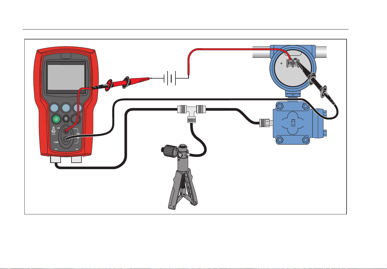
Pressure-to-Current Transmitter Calibration
To calibrate a pressure-to-current transmitter (P/I):
1. Connect the Product and the pump to the transmitter.
See Figure 7.
2. Apply pressure with the pump.
3. Measure the current output of the transmitter.
4. Ensure the reading is correct. If not, adjust the
transmitter as necessary.
Note
Use low-volume tubing when possible.
1.888.610.7664 sales@GlobalTestSupply.com
Fluke-Direct.com
721Ex
Users Manual
28
F1 F2 F3
ZERO
-
External
Loop Supply
hvf018.eps
Figure 7. Pressure-to-Current Transmitter Connections
1.888.610.7664 sales@GlobalTestSupply.com
Fluke-Direct.com

Pressure Calibrator
Transmitter Calibration
29
Ranges and Resolution
Ranges and resolutions for the Product are shown in Table 4.
Table 4. Ranges and Resolutions
Range (PSI) 16 36 100 300 500 1000 1500 3000 5000
Burst Pressure 60 120 400 1200 2000 4000 6000 9000 10000
Proof Pressure
(PSI)
35 70 200 600 1000 2000 3000 6000 7000
Engineering Unit Factor
psi 1 16 36 100 300 500 1000 1500 3000 5000
bar 0.06894757 1.1032 2.4821 6.8947 20.684 34.474 68.947 103.42 206.84 344.74
mbar 68.94757 1103.2 2482.1 6894.8 20684 34474 68948 N/A N/A N/A
kPa 6.894757 110.32 248.21 689.48 2068.4 3447.4 6894.8 10342 20684 34474
MPa 0.00689476 0.1103 0.2482 0.6894 2.0684 3.4474 6.8948 10.342 20.684 34.474
kg/cm2 0.07030697 1.1249 2.5311 7.0307 21.092 35.153 70.307 105.46 210.92 351.53
cmH20 @ 4 °C
70.3089 1124.9 2531.1 7030.9 21093 35154 70309 N/A N/A N/A
cmH20 @ 20 °C
70.4336 1126.9 2535.6 7043.4 21130 35217 70434 N/A N/A N/A
mmH20 @ 4 °C
703.089 11249 25311 70309 N/A N/A N/A N/A N/A N/A
mmH20 @ 20 °C
704.336 11269 25356 70434 N/A N/A N/A N/A N/A N/A
inH20 @ 4 °C
27.68067 442.89 996.50 2768.1 8304.2 13840 27681 41521 83042 N/A
inH20 @ 20 °C
27.72977 443.68 998.27 2773.0 8318.9 13865 27730 41595 83189 N/A
inH20 @ 60 °F
27.70759 443.32 997.47 2770.8 8312.3 13854 27708 41561 83123 N/A
mmHg @ 0 °C
51.71508 827.44 1861.7 5171.5 15515 25858 51715 77573 N/A N/A
inHg @ 0 °C
2.03602 32.576 73.297 203.60 610.81 1018.0 2036.0 3054.0 6108.1 10180
• Proof pressure - maximum allowable pressure without a shift in calibration.
• Burst pressure - sensor damaged or destroyed; some risk of personnel injury.
1.888.610.7664 sales@GlobalTestSupply.com
Fluke-Direct.com

721Ex
Users Manual
30
Maintenance
Replace the Batteries
If the batteries discharge too far, the Product
automatically shuts down to prevent battery leakage.
Warning
To prevent possible electrical shock, fire, or
personal injury:
• Remove the batteries if the Product is
not used for an extended period of time,
or if stored in temperatures above 50 °C.
If the batteries are not removed, battery
leakage can damage the Product.
• Replace the batteries when the low
battery indicator shows to prevent
incorrect measurements.
• Be sure that the battery polarity is
correct to prevent battery leakage.
• Repair the Product before use if the
battery leaks.
• The battery door must be closed and
locked before you operate the Product.
• Only change batteries in an area known
to be non-hazardous.
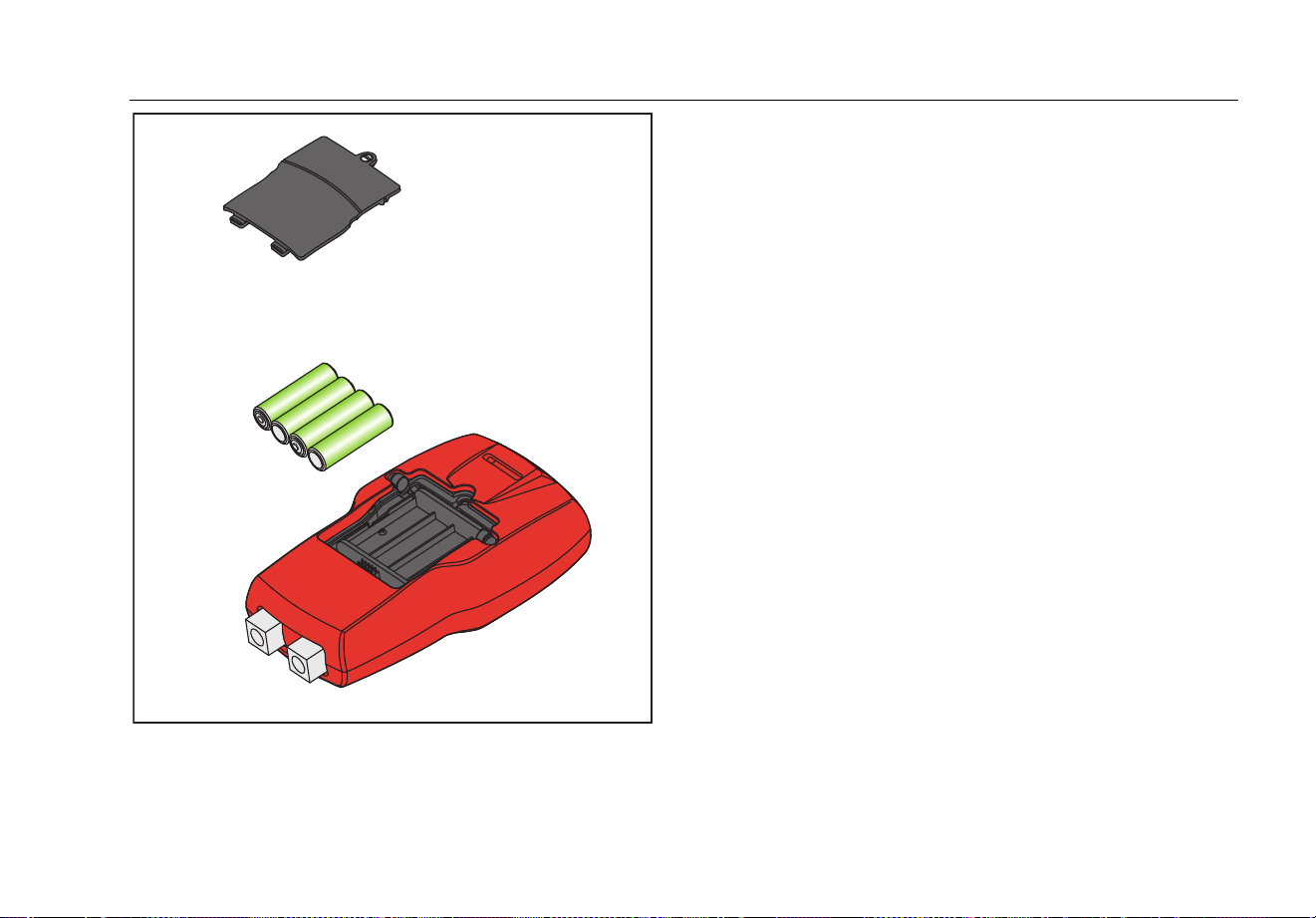
To change the batteries, see Figure 8:
1. Turn off the Product.
2. Turn the Product so that the display is down.
3. With a flat-head screwdriver, remove the battery door
screw.
4. Replace the four AA batteries with new batteries.
Make sure that the polarity on the batteries is correct.
See Table 5 for a list of approved batteries.
5. Replace the battery door.
6. Tighten the battery door screw.
Table 5. Approved Batteries
Battery Manufacturer
(All Batteries Alkaline 1.5 V)
Type
Duracell MN1500
Rayovac Max Plus 815
Eveready (Energizer) E91
Panasonic LR6XWA
1.888.610.7664 sales@GlobalTestSupply.com
Fluke-Direct.com
Pressure Calibrator
Maintenance
31
hvf061.eps
Figure 8. Battery Replacement
Clean the Product
Caution
To avoid damaged to the Product:
• Do not use solvents or abrasive
cleansers.
• Do not allow water into the case.
Clean the Product with a soft cloth dampened with water
or water and mild soap.
1.888.610.7664 sales@GlobalTestSupply.com
Fluke-Direct.com

721Ex
Users Manual
32
User-Replaceable Parts and
Accessories
Warning
To prevent possible electrical shock, fire, or
personal injury, use only specified
replacement parts.
User-replaceable parts are listed in Table 6 and shown
in Figure 9 . For more information about these items,
contact a Fluke representative. See the “Contact Fluke”
section of this manual.
Table 6. User-Replaceable Parts and Accessories
Item Description
Part
Number
Red Holster
4497306
TL7X Probe Cap, Red 3986579
TL7X Probe Cap, Black 3986568
TPAK80-4-2002, Magnet
Strap
669952
TPAK80-4-8001, Strap 9
inches
669960
Item Description
Part
Number
AA Alkaline Batteries 376756
Safety Sheet 4561164
Quick Reference Guide 4561158
Users Manual CD 4561173
Not Shown
Rubber Feet 4364579
Not Shown
Fluke-720RTD Probe for 721
and 719Pro
4366669
Not Shown
Test Lead Set Variable
[1]
Not Shown
Alligator Clip, Red Variable
[1]
Not Shown
Alligator Clip, Black Variable
[1]
[1] See www.fluke.com for more information about the
test leads and alligator clips available for your
region.
1.888.610.7664 sales@GlobalTestSupply.com
Fluke-Direct.com

Pressure Calibrator
User-Replaceable Parts and Accessories
33
1
3
2
5
4
6
7
8
hvf065.eps
Figure 9. User-Replaceable Parts and Accessories
1.888.610.7664 sales@GlobalTestSupply.com
Fluke-Direct.com

721Ex
Users Manual
34
Specifications
(15 °C to 35 °C unless otherwise noted)
Environmental
Operating Temperature ............................ -10 °C to +45 °C (14 °F to +113 °F)
Storage
With Batteries ........................................ Per battery manufacturer’s specification, not to exceed storage specification without batteries.
Without Batteries ................................... -20 °C to +60 °C (-4 °F to +140 °F)
Altitude ...................................................... 2000 m
Power Requirements ............................... 6 V dc
Batteries .................................................... 4 AA batteries (alkaline)
Battery Life ................................................ >35 hours, typical usage
Electrical and Temperature Measurement (1 year)
Function Range Resolution Accuracy
mA Measure 0 to 24 mA 0.001 mA
±0.015 % of rdg ±0.002 mA
*Temperature measure
(RTD/Ohms)
-40 °C to 150 °C (-40 °F to 302 °F) 0.01 °C, 0.01 °F
±0.015 % of rdg ±0.02 Ω; ±0.1 °C (±0.2 °F)
±0.25 °C (± 0.45 °F) combined uncertainty when us
ing
720 RT
D probe accessory
*Temperature measurement requires optional 720RTD Pt-100 RTD probe available as an accessory.
1.888.610.7664 sales@GlobalTestSupply.com
Fluke-Direct.com

Pressure Calibrator
Specifications
35
Physical
Dimensions (with holster) ......................... (H x W x D) (20 x 11 x 5.8) cm, (7.9 x 4.3 x 2.3) in
Weight (with holster) ................................ 0.539 kg (1 lb 3 oz)
Ingress Protection ..................................... IEC 60529 - IP40
Connectors/Ports
Pressure .............................................. Two, 1/8 in NPT
RTD ..................................................... RTD probe
Temperature Effect (all functions) ............. No effect on accuracy on all functions from 15 °C to 35 °C
Add ±0.002
% Full Scale/°C for temps outside of 15 °C to 35 °C
1.888.610.7664 sales@GlobalTestSupply.com
Fluke-Direct.com

721Ex
Users Manual
36
1-year Specifications Low Pressure Sensor High Pressure Sensor
Model
Calibrator
Description
Range
Sensor 1
Resolution
Sensor 1
Accuracy
Sensor 1
Range
Sensor 2
Resolution
Sensor 2
Accuracy
Sensor 2
721Ex-
1601
16 PSIG, 100 PSIG
-14 psi + 16 psi
-0.97 bar to
1.1 bar
0.001 psi,
0.0001 bar
0.025 % of
full scale
-12 psi to +100 psi
-0.83 bar to
6.9 bar
0.01 psi
0.0001 bar
0.025 % of full
scale
721Ex-
1603
16 PSIG, 300 PSIG
-12 psi to +300 psi
-0.83 bar to 20 bar
0.01 psi
0.001 bar
721Ex-
1605
16 PSIG, 500 PSIG
-12 psi to +500 psi
-0.83 bar to
34.5 bar
0.01 psi
0.001 bar
721Ex-
1610
16 PSIG, 1000
PSIG
0 psi to +1000 psi
0.00 bar to 69 bar
0.1 psi
0.001 bar
721Ex-
1615
16 PSIG, 1500
PSIG
0 psi to +1500 psi
0.00 bar to
103.4 bar
0.1 psi
0.001 bar
721Ex-
1630
16 PSIG, 3000
PSIG
0 psi to +3000 psi
0.00 bar to
200 bar
0.1 psi
0.01 bar
721Ex-
1650
16 PSIG, 5000
PSIG
0 psi to +5000 psi
0.00 bar to
345 bar
0.1 psi
0.01 bar
0.035 % of full
scale
1.888.610.7664 sales@GlobalTestSupply.com
Fluke-Direct.com

Pressure Calibrator
Specifications
37
1-year Specifications Low Pressure Sensor High Pressure Sensor
Model
Calibrator
Description
Range
Sensor 1
Resolution
Sensor 1
Accuracy
Sensor 1
Range
Sensor 2
Resolution
Sensor 2
Accuracy
Sensor 2
721Ex-
3601
36 PSIG, 100 PSIG
-14 psi + 36 psi
-0.97 bar to
2.48 bar
0.001 psi,
0.0001 bar
0.025 % of full
scale
-12 psi to +100 psi
-0.83 bar to
6.9 bar
0.01 psi
0.0001 bar
0.025 % of
full scale
721Ex-
3603
36 PSIG, 300 PSIG
-12 psi to +300 psi
-0.83 bar to 20 bar
0.01 psi
0.001 bar
721Ex-
3605
36 PSIG, 500 PSIG
-12 psi to +500 psi
-0.83 bar to
34.5 bar
0.01 psi
0.001 bar
721Ex-
3610
36 PSIG, 1000
PSIG
0 psi to +1000 psi
0.00 bar to 69 bar
0.1 psi
0.001 bar
721Ex-
3615
36 PSIG, 1500
PSIG
0 psi to +1500 psi
0.00 bar to
103.4 bar
0.1 psi
0.01 bar
721Ex-
3630
36 PSIG, 3000
PSIG
0 psi to +3000 psi
0.00 bar to
200 bar
0.1 psi
0.01 bar
721Ex-
3650
36 PSIG, 5000
PSIG
0 psi to +5000 psi
0.00 bar to
345 bar
0.1 psi
0.01 bar
0.035 % of
full scale
1.888.610.7664 sales@GlobalTestSupply.com
Fluke-Direct.com

721Ex
Users Manual
38
Electromagnetic Compatibility (EMC) ........... IEC 61326-1 (Portable); IEC 61326-2-2, CISPR 11, Group 1, Class A
Group 1 equipment: group 1 has intentionally generated and/or use conductively coupled radio-
frequency energy which is necessary for the internal functioning of the equipment itself.
Class A equipment is equipment suitable for use in all establishments other than domestic and
those directly connected to a low voltage power supply network which supplies buildings used
for domestic purposes. Caution - There may be potential difficulties in ensuring electromagnetic
compatibility in other environments, due to conducted and radiated disturbances.
USA (FCC) – 47 CFR 15 subpart B, this product is considered an exempt device per clause
15.103
Applies to use in Korea only. Class A Equipment (Industrial Broadcasting & Communication
Equipment)
[1]
[1] This product
meets requirements for industrial (Class A) electromagnetic wave e
quipment
and the seller or
user should take notice of it. This equipment is intended for use in bu
siness
environments and is not to be used in homes.
Ex-Haza
rdous Area Markings .......................
Ex ia IIB T3 Gb (Ta= -10… +45 °C)
KEMA 10 ATEX 0168X
Ex ia IIB T3 Gb (Ta= -10…+45 °C)
II 2 G IECEX CSA 10.0013X
Manufactured by Martel Electronics, Inc.,
3 Corporate Park Dr.
Derry, NH, USA
Entity Parameters ......................................... MEASUREMENT JACKS:
Ui = 30 V; Li = 80 mA; Pi = 750 mW; Ci = 0 μF; Li = 0 mH
Uo = 7, 14 V; lo = 1,12 mA; Po = 2 mW: Co = 240 μF; Lo = 1 H
Circular Connector: FOR USE WITH LTP100A RTD PROBE ONLY
1.888.610.7664 sales@GlobalTestSupply.com
Fluke-Direct.com