
®
718 Series
Pressure Calibrator
Users Manual
July 1998 Rev. 4, 3/06
© 1998-2006 Fluke Corporation. All rights reserved. Printed in U.S.A.
All product names are trademarks of their respective companies.
1.888.610.7664 sales@GlobalTestSupply.com
Fluke-Direct
.com

i
Table of Contents
Title Page
Introduction..................................................................................................................... 1
Safety Information .......................................................................................................... 2
Getting Acquainted with the Calibrator ........................................................................... 6
Power Saver.............................................................................................................. 6
Switch Test..................................................................................................................... 8
Zeroing with Absolute Pressure Modules ....................................................................... 9
Calibrating a P/I Transmitter........................................................................................... 10
Using the Internal Pump ............................................................................................ 10
Pump Valve Assembly Cleaning Instructions ................................................................. 15
Using an External Pump................................................................................................. 16
External Fluke Pressure Module Compatibility ............................................................... 18
Sourcing Loop Voltage ................................................................................................... 19
Percent Error Setup........................................................................................................ 19
Maintenance................................................................................................................... 20
In Case of Difficulty.................................................................................................... 20
Cleaning .................................................................................................................... 20
Calibration ................................................................................................................. 20
1.888.610.7664 sales@GlobalTestSupply.com
Fluke-Direct
.com

718 Series
Users Manual
ii
Replacing the Batteries ............................................................................................. 21
Parts and Accessories ................................................................................................... 22
Specifications................................................................................................................. 25
Pressure Sensor Input .............................................................................................. 25
Pressure Module Input .............................................................................................. 25
DC mA Input ............................................................................................................. 25
Loop Supply .............................................................................................................. 25
General Specifications .............................................................................................. 26
How to Contact Fluke..................................................................................................... 27
1.888.610.7664 sales@GlobalTestSupply.com
Fluke-Direct
.com

iii
List of Tables
Table Title Page
1. Input Units ............................................................................................................................. 2
2. Safety Information ................................................................................................................. 3
3. International Electrical Symbols............................................................................................. 5
4. Pushbutton Functions............................................................................................................ 7
5. Pump Features...................................................................................................................... 10
6. Recommended Pressure Modules ........................................................................................ 14
7. Fluke Pressure Module Compatibility .................................................................................... 18
8. Replacement Parts................................................................................................................ 22
1.888.610.7664 sales@GlobalTestSupply.com
Fluke-Direct
.com

v
List of Figures
Figure Title Page
1. Connection Technique........................................................................................................... 5
2. Front Panel Features............................................................................................................. 6
3. Pump Features...................................................................................................................... 9
4. Internal Pressure Sensor with Internal Pump ........................................................................ 12
5. Pressure Module with Internal Pump..................................................................................... 13
6. Pressure Module with External Pump.................................................................................... 17
7. Sourcing Loop Voltage .......................................................................................................... 19
8. Battery Replacement............................................................................................................. 21
9. Replacement Parts................................................................................................................ 24
1.888.610.7664 sales@GlobalTestSupply.com
Fluke-Direct
.com

1
Pressure Calibrator
Introduction
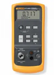
The Fluke 718 Series Pressure Calibrators do the
following:
• Calibrate P/I (pressure to current) transmitters
• Measure pressure via a 1/8-inch NPT pressure fitting
and an internal pressure sensor or via a Fluke 700
Series Pressure Module
•
Source pressure
• Measure current up to 24 mA
• Simultaneously display pressure and current
measurements.
• Supply loop voltage
• Calculate mA percentage in Percent Mode
• Calculate mA error % in Percent Error Mode
The 718 Pressure Calibrators (hereafter, “the Calibrator”)
include:
• 718 1G
• 718 30G
• 718 100G
• 718 300G
The Calibrator makes 5-digit pressure readings in the
following units: psi, inH
2
O at 4 °C, inH
2
O at 20 °C, kPa,
cmH
2
O at 4 °C, cmH
2
O at 20 °C, bar, mbar, kg/cm
2
, inHg,
and mmHg.
Pressure sensor specifications are as listed under
“Pressure Sensor Input”.
The Calibrator measures pressure sensor inputs in the
units shown in Table 1.
For pressure modules, full scale readings for all pressure
ranges can be made in psi, kPa, and inHg units. To avoid
display overflow, full scale readings are limited to 1000 psi
in cmH
2
O, mbar, and mmHg units, and 3000 psi in inH
2
O
units. Pressures of at least 15 psi must be measured for
meaningful readings in bar and kg/cm
2
units.
Your Calibrator is supplied with a holster, two installed 9 V
alkaline batteries, one set of TL75 test leads, one set of
AC70A alligator clips, one 700-ILF In-Line Filter (to protect
the pump), a Product Overview Manual, and a CD-Rom.
If the Calibrator is damaged or something is missing,
contact the place of purchase immediately. Contact your
Fluke distributor for information about accessories. See
1.888.610.7664 sales@GlobalTestSupply.com
Fluke-Direct
.com

718 Series
Users Manual
2
“How to Contact Fluke.” To order replacement parts or
spares, see “Parts and Accessories.”
Table 1. Input Units
Displayed Pressure Units
psi
inH
2
O at 4°C
inH
2
O at 20°C
cmH
2
O at 4°C
cmH
2
O at 20°C
bar
mbar
kPa
inHg
mmHg
kg/cm
2
Safety Information
Use the Calibrator only as specified in this Users Manual,
otherwise the protection provided by the Calibrator may be
impaired.
A Warning identifies conditions and actions that pose
hazard(s) to the user; a Caution identifies conditions and
actions that may damage the Calibrator or the equipment
under test.
1.888.610.7664 sales@GlobalTestSupply.com
Fluke-Direct
.com

Pressure Calibrator
Safety Information
3
Table 2. Safety Information
XW Warning
To avoid possible electric shock or personal injury:
• Never apply more than 30 V between the mA terminals, or between either of the mA terminals and earth
ground.
• Do not use the Calibrator to make measurements in a CAT II, CAT III, or a CAT IV environment.
CAT I equipment is designed to protect against transient from high-voltage, low-energy sources, such
as electronic circuits or a copy machine
• Remove the test leads from the Calibrator before you open the battery door.
• Make sure the battery door is closed and latched before you operate the Calibrator.
• Do not operate the Calibrator if it is damaged.
• Do not operate the Calibrator around explosive gas, vapor, or dust.
• When using probes, keep fingers behind the finger guards on the probes.
• Use only two 9 V batteries, properly installed in the Calibrator case, to power the Calibrator.
• Follow all equipment safety procedures.
• Turn off circuit power before connecting the Calibrator mA and COM terminals in the circuit. Place
Calibrator in series with the circuit.
• When servicing the Calibrator, use only specified replacement parts.
• Do not allow water inside the case.
1.888.610.7664 sales@GlobalTestSupply.com
Fluke-Direct
.com

718 Series
Users Manual
4
Table 2. Safety Information (cont.)
XW Warning
• To avoid false readings, which could lead to possible electric shock or personal injury, replace the
battery as soon as the battery indicator
B
appears.
• To avoid a violent release of pressure in a pressurized system, shut off the valve and slowly bleed off
the pressure before you attach or detach the internal pressure sensor or pressure module fitting to the
pressure line.
• To avoid over pressure damages, do not apply pressure that exceeds the limits listed in the Pressure
Specifications table in the “Specifications” section.
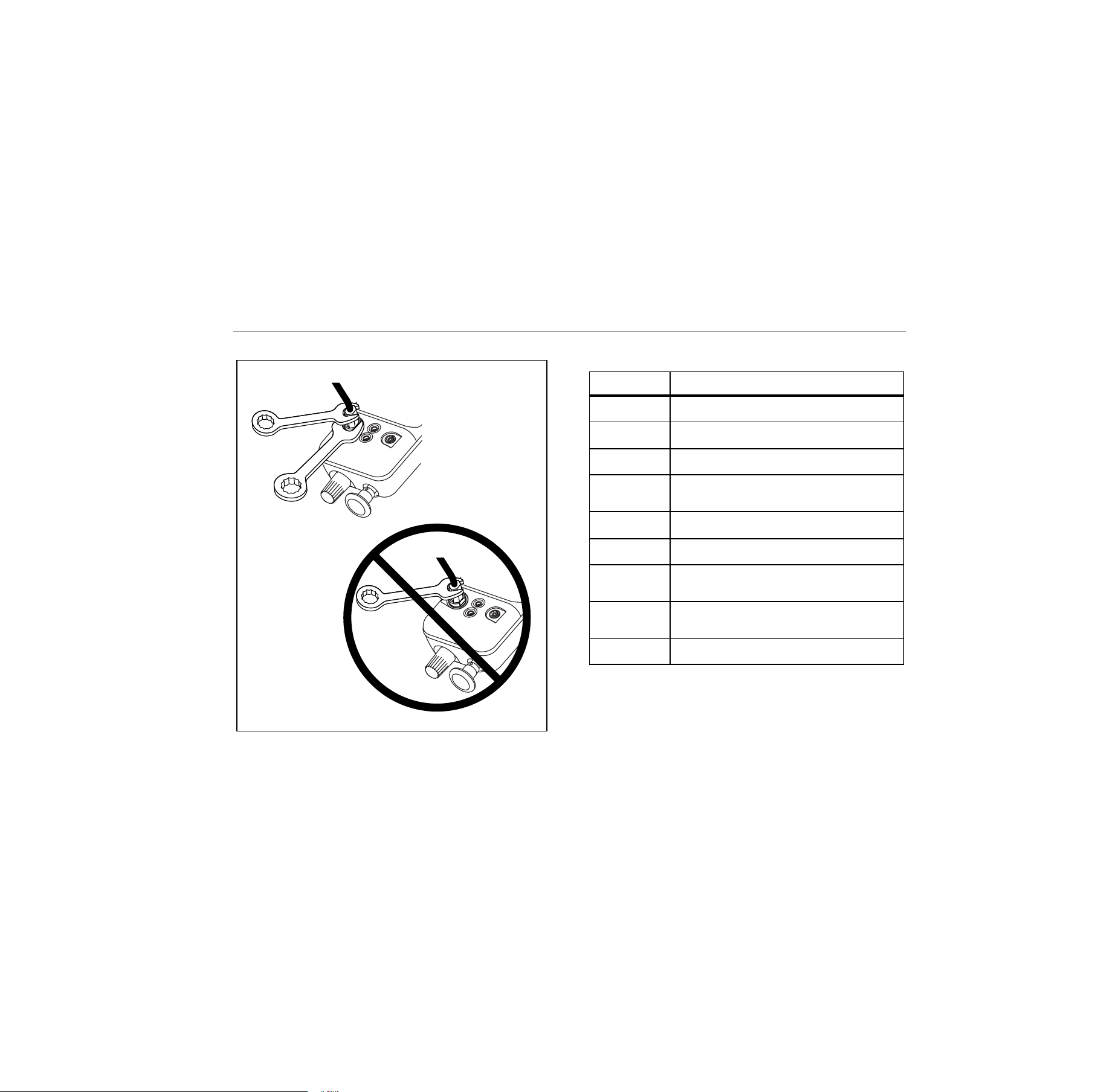
• To avoid mechanically damaging the Calibrator, do not apply torque between the pressure fitting and
the Calibrator case. See Figure 1 for the proper use of tools.
• To avoid misleading readings, disconnect the pressure module connector at the Calibrator.
• To avoid damage to the pressure module, refer to the related Instruction Sheet.
• To avoid damage to the pump, use with dry air and non-corrosive gases only. Check test leads for
continuity before using. Inspect Calibrator for cracks or damage, do not use the probes if they are
damaged or show high resistance.
1.888.610.7664 sales@GlobalTestSupply.com
Fluke-Direct
.com
Pressure Calibrator
Safety Information
5
Hold in
fixed
position
wh001f.eps
Figure 1. Connection Technique
Table 3. International Electrical Symbols
Symbol Meaning
J
Earth ground
I
Fuse
M
Battery
W
Refer to this instruction sheet for
information about this feature.
X
Hazardous voltage. Risk of electric
shock.
T
Double insulated
)
Conforms to relevant Canadian
Standards Association directives.
P
Conforms to relevant European Union
directives
f
Pressure
1.888.610.7664 sales@GlobalTestSupply.com
Fluke-Direct
.com
718 Series
Users Manual
6
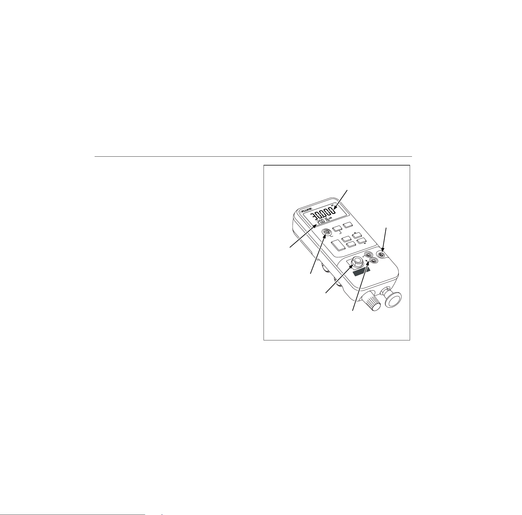
Getting Acquainted with the Calibrator
Press
O
to turn the Calibrator on and off. The Calibrator
displays pressure and current measurements
simultaneously. See Figure 2.
The upper part of the display shows the applied pressure
or vacuum. (Vacuum is shown as a negative value.) Press
U
to select a different unit. When you cycle the power
off and on, the Calibrator retains the unit you last used.
The lower part of the display shows the current (up to 24
mA) applied to the current (mA) inputs.
To source loop voltage, press
U while pressing O on.
Pushbutton operation is described in Table 4. Pump
features are shown in Figure 3 and described in Table 5.
Power Saver
The Calibrator automatically turns off after 30 minutes of
inactivity. To reduce this time or disable this feature:
1. With the Calibrator OFF, press
O.
2. P.S. xx is displayed, where xx is the turn-off time in
minutes. OFF means the power saver is disabled.
3. Press
h (W) to decrease or a(X) to increase
the turn-off time.
4. To disable, press
h until the display shows OFF.
The Calibrator resumes normal operation after 2 seconds.
RANGE
-1 O 1 PSI
MAX 5 PSI 34.5
P
-7 O 7 kP
Current mA
measurement
Pressure
measurement
Pressure
module input
Pressure
sensor input
(Install filter here)
Current
input
On/Off Button
718
PRESSURE
CALIBRATOR
HOLD
COM
mA
30V
MAX
0-30psi 0-206kPa
RANGE
UNITS
ZERO
DAMP
mA
MODE
HOLD
LOOP
POWER
B
A
R
O
M
E
T
R
IC
A
D
J
.
MIN
MAX
SWITCH
TEST
ENTER
wh005f.eps
Figure 2. Front Panel Features
1.888.610.7664 sales@GlobalTestSupply.com
Fluke-Direct
.com

Pressure Calibrator
Getting Acquainted with the Calibrator
7
Table 4. Pushbutton Functions
Pushbutton Description
U
Press to select a different pressure unit. All units are available when the pressure sensor input is used. For
higher pressure module inputs, inappropriate (out-of-range) units are not available. Press
O
on while
pressing
U
to source loop voltage.
D
ENTER
Turns pressure reading damping on and off. With damping on, the Calibrator averages several
measurements before displaying a reading. Press to confirm selection of 0% and 100% output parameters.
Z
Press to zero the pressure display. Vent pressure to atmosphere before you press this pushbutton. With an
Absolute Pressure Module, see special instructions below.
N
Press to read the minimum pressure and current readings since power was turned on or the registers were
cleared. Press again to read the maximum pressure and current readings since power was turned on. Press
and hold for 3 seconds to clear the MIN/MAX registers.
S
Press to perform switch test.
Z
a
Press to toggle the mA display mode between mA, mA Percent, and mA Percent Error.
h
W
Press
h
to freeze the display. The
g
symbol appears on the display. Press
h
again to resume
normal operation.
1.888.610.7664 sales@GlobalTestSupply.com
Fluke-Direct
.com

718 Series
Users Manual
8
Switch Test
To perform a switch test, do the following:
Note
This example uses a normally closed switch. The
procedure is the same for an open switch but the
display reads OPEN instead of CLOSE.
1. Connect the Calibrator mA and COM terminals to the
switch using the pressure switch terminals and
connect an external pump between the Calibrator and
the pressure switch. The polarity of the terminals does
not matter.
Note
If using an external pump, connect the pump to
the Calibrator and to the input of the switch using
a tee fitting.
2. Make sure the vent on the pump is open and zero the
Calibrator if necessary. Close the vent after zeroing
the Calibrator.
3. Press
S to enter pressure switch test mode. The
Calibrator will display CLOSE instead of a mA
measurement.
4. Apply pressure with the pump slowly until the switch
opens.
Note
In the switch test mode, the display update rate is
increased to help capture changing pressure
inputs. Even with the enhanced sample rate,
pressuring the device under test should be done
slowly to ensure accurate readings.
5. OPEN is displayed once the switch is open. Bleed the
pump slowly until the pressure switch closes. RCL
appears on the display.
6. Press
S to read the pressure values for when the
swith opened, for when it closed, and for the
deadband
Hold
S for 3 seconds to reset Switch Test mode; hold
any other key for 3 seconds to exit.
1.888.610.7664 sales@GlobalTestSupply.com
Fluke-Direct
.com
Pressure Calibrator
Zeroing with Absolute Pressure Modules
9
Zeroing with Absolute Pressure Modules
For zeroing, adjust the Calibrator to read a known
pressure. This can be barometric pressure, if it is
accurately known, for all but the 700PA3 module. An
accurate pressure standard can also apply a pressure
within range for any Absolute Pressure Module. Adjust the
Calibrator reading as follows:
1. Press and hold
Z
.
2. Press
a(Z) to increase or
h
(Y) to decrease
the Calibrator reading to equal the applied pressure.
3. Release
Z
to exit the zeroing procedure.
Press the
U button to convert to any convenient
measurement display unit.
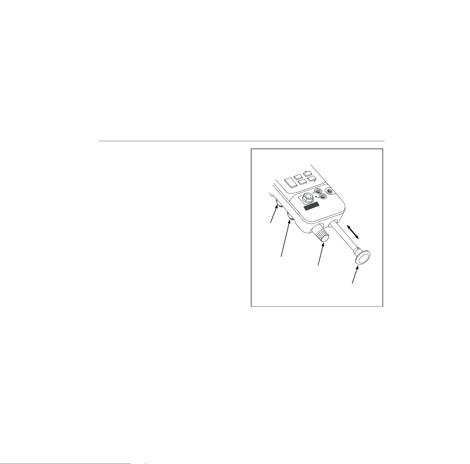
Pressure/
Vacuum
Switch
Fine
Adjustment
Knob
Internal Pump
Pressure/Vacuum
Release
Control
COM
mA
30V
MAX
0-30psi 0-206kPa
RANGE
ZERO
HOLD
B
A
R
O
M
E
T
R
IC
A
D
J
.
mA
MODE
RANGE
O 1 PSI
MAX 5 PSI
P
-7 O 7 kP
MIN
MAX
SWITCH
TEST
wh009f.eps
Figure 3. Pump Features
1.888.610.7664 sales@GlobalTestSupply.com
Fluke-Direct
.com

718 Series
Users Manual
10
Table 5. Pump Features
Item Description
Pressure
Vacuum
Switch
Rotate forward (clockwise) for pressure,
backward (counter-clockwise) for
vacuum.
Pressure
Vacuum
Release
Valve
Rotate fully backward (counter-
clockwise) to release all pressure or
vacuum. (Rotate slightly for partial
release.) Rotate fully forward (clockwise)
to close valve.
Fine
Adjustment
Knob
Rotate either direction for precise
adjustment of applied pressure or
vacuum. Full rotation is about 30 turns.
Internal
Pump
Increase pressure on the inward stroke.
In vacuum mode, decrease pressure on
the outward stroke.
Calibrating a P/I Transmitter
To calibrate a P/I (pressure to current) transmitter, apply a
pressure to the transmitter and measure the transmitter’s
current loop output. You can apply pressure with the
Calibrator’s internal pump or with an external pump.
XW Warning
To avoid a violent release of pressure or vacuum,
always depressurize the system slowly using the
pressure/vacuum release control before detaching
any pressure line.
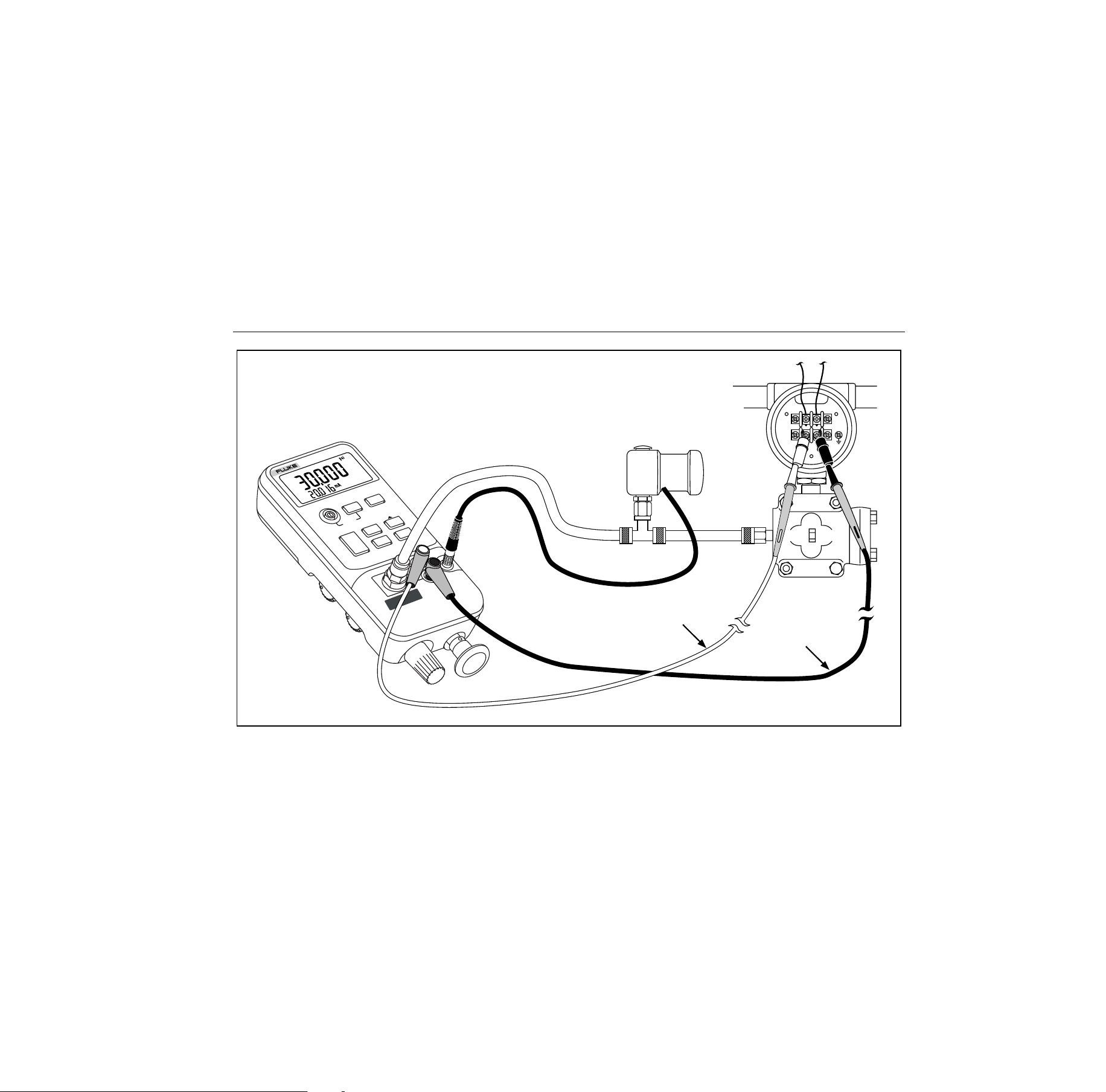
Using the Internal Pump
The internal pump can provide the rated pressure for all
Model 718 Calibrators.
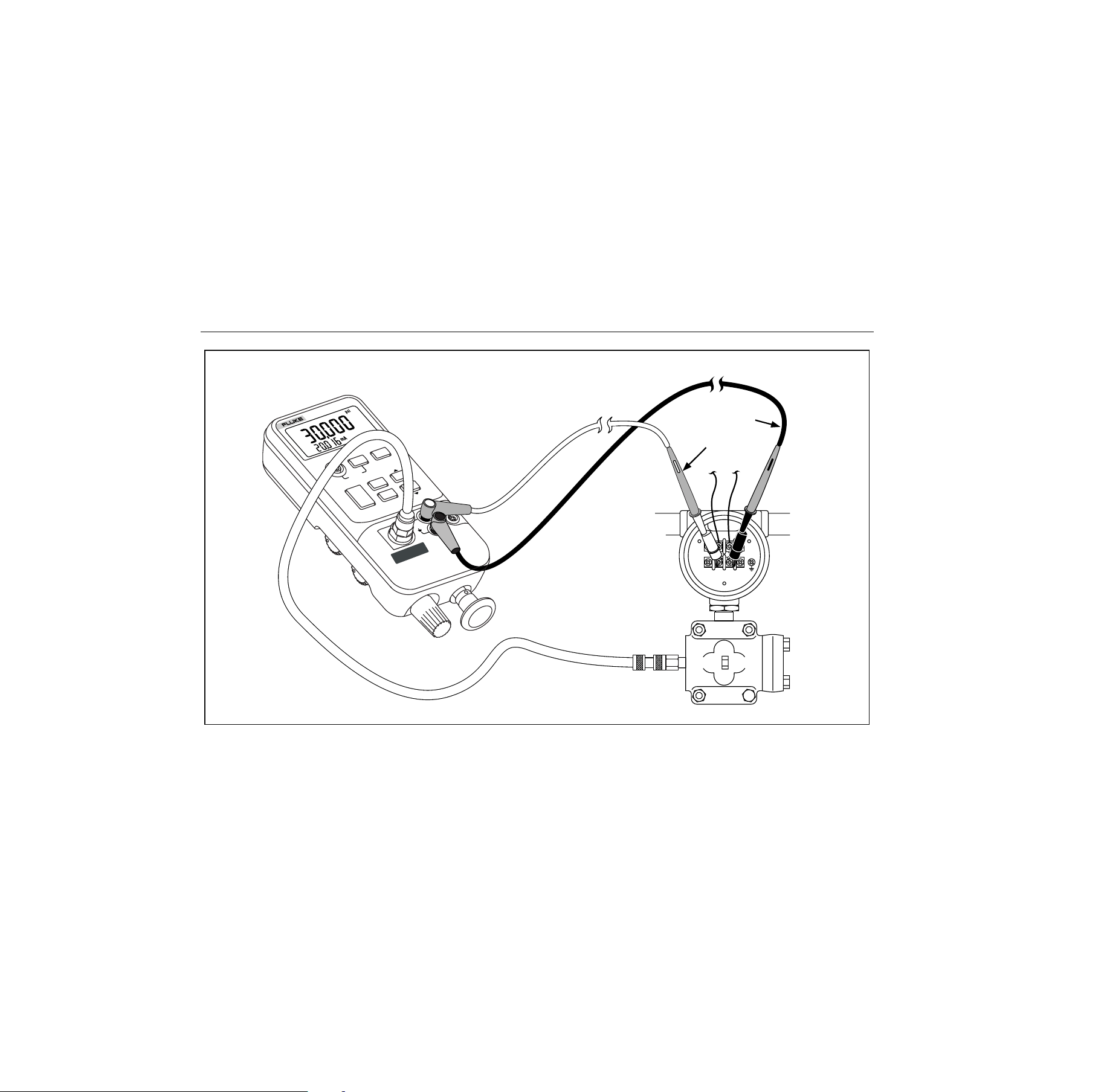
The preferred use for the internal pump is shown in Figure
4, where the Calibrator displays pressure measured with
the internal sensor and provided by the internal pump.
The internal pump can also be used with certain Fluke 700
Series Pressure Modules. In this case, pressure measured
by the Pressure Module is displayed by the Calibrator.
Appropriate pressure modules for each Calibrator model
are identified in Table 6 . Figure 5 shows the internal pump
being used with a pressure module.
1.888.610.7664 sales@GlobalTestSupply.com
Fluke-Direct
.com

Pressure Calibrator
Calibrating a P/I Transmitter
11
XW Warning
If both a pressure module and the internal
sensor are connected, the Calibrator displays
ONLY the pressure module measurement.
To use the Calibrator’s internal pump, refer to Figure 3 and
perform the following steps:
1. Depressurize and drain the line before connecting the
Calibrator.
2. Connect the pressure transmitter to the Calibrator
internal sensor as shown in Figure 4 (for internal
pressure sensor measurements) or Figure 5 (for
pressure module measurements.)
Note
To avoid leaks, use Teflon tape or similar sealant
on all pressure connections.
3. Make sure the pressure/vacuum switch is in the
desired position. Forward (clockwise) is for pressure;
backward (counter-clockwise) is for vacuum.
4. Turn the pressure/vacuum release control backward
(counter-clockwise) to vent pressure/vacuum from the
pump.
5. Press
Z to zero the pressure display.
6. Turn the fine adjustment knob to mid-range.
7. Turn the pressure/vacuum release control forward
(clockwise) to close the release valve.
8. Work the pump handle in and out to apply
incrementally larger pressure/vacuum changes.
Shorten the stroke to apply smaller increments of
pressure/vacuum change.
9. To make very small pressure/vacuum changes, use
the fine adjustment knob.
Note
This knob adjusts a small internal reservoir to
vary the total volume. With larger external
pressure/vacuum volumes, this control will adjust
pressure or vacuum within a smaller range.
10. Depressurize the system before disconnecting the
pressure line.
1.888.610.7664 sales@GlobalTestSupply.com
Fluke-Direct
.com
718 Series
Users Manual
12
mA
MODE
RANGE
O 1 PSI
MAX 5 PSI
P
-7 O 7 kP
MIN
MAX
SWITCH
TEST
COM
mA
30V
MAX
0-30psi 0-206kPa
RANGE
SIGNAL
TEST
+
–
Red
Black
718
PRESSURE
CALIBRATOR
HOLD
UNITS
ZERO
DAMP
HOLD
LOOP
POWER
BAR
OM
ETR
IC AD
J.
wh002f.eps
Figure 4. Internal Pressure Sensor with Internal Pump
1.888.610.7664 sales@GlobalTestSupply.com
Fluke-Direct
.com
Pressure Calibrator
Calibrating a P/I Transmitter
13
mA
MODE
RANGE
O 1 PSI
MAX 5 PSI P
-7 O 7 kP
MIN
MAX
SWITCH
TEST
CO
M
m
A
30V
MAX
0-30psi 0-206kPa
RANGE
UNITS
ZERO
DAMP
HOLD
LOOP
POWER
B
A
RO
M
ETR
IC
A
D
J.
SIGNAL
TEST
+
–
Pressure Module
Red
Black
718
PRESSURE
CALIBRATOR
HOLD
wh010f.eps
Figure 5. Pressure Module with Internal Pump
1.888.610.7664 sales@GlobalTestSupply.com
Fluke-Direct
.com

718 Series
Users Manual
14
Table 6. Recommended Pressure Modules
External
Pump
Internal
Pump
Pressure
Module
718
all models
718
1G
718
30G
718
100G
718
300G
700 P00 X X
700 P01 X X
700 P02 X X X X X
700 P22 X X X X X
700 P03 X X X X
700 P23 X X X X
700 P04 X X X X
700 P24 X X X X
700 P05 X X X X
700 P06 X X X
700 P27 X X
700 P07 X
700 P08 X
700 P09 X
External
pump
Internal Pump
Pressure
Module
All 718
models
718
1G
718
30G
718
100G
718
300G
700 PA3 X X X X
700 PA4 X X X X
700 PA5 X X X X
700 PA6 X X X
700 PV3 X X X X
700 PV4 X X X X
700 PD2 X X X X X
700 PD3 X X X X
700 PD4 X X X X
700 PD5 X X X X
700 PD6 X X X
700 PD7 X X
700 D29 X
700 P30 X
700 P31 X
1.888.610.7664 sales@GlobalTestSupply.com
Fluke-Direct
.com

Pressure Calibrator
Pump Valve Assembly Cleaning Instructions
15
Pump Valve Assembly Cleaning
Instructions
1. Using a small screwdriver, remove the two valve
retention caps located in the oval shaped opening on
the underside of the Calibrator.
2. After the caps have been removed, gently remove the
spring and o-ring assembly.
3. Set aside the valve assemblies in a safe area and
clean out the valve body using a cotton swab soaked
in IPA (isopropyl alcohol).
4. Repeat this process several times using a new cotton
swab each time until there is no remaining sign of
residue.
5. Pump the unit several times and check again for
residue.
6. Clean the o-ring assembly and o-ring on the retention
caps with IPA and inspect the o-rings closely for any
cuts, nicks, or wear. Replace if needed.
7. Inspect the springs for wear or loss of tension. They
should be approximately 8.6 mm long in the relaxed
state. If they are shorter than this, they may not allow
the o-ring to seat properly. Replace if needed.
8. Once all parts have been cleaned and inspected,
reinstall the o-ring and spring assemblies into the
valve body.
9. Reinstall the retention caps and gently tighten the
cap.
10. Seal the output of the Calibrator and pump up the unit
to at least 50 % its rated pressure.
11. Release the pressure and repeat several times to
ensure that the o-rings seat properly.
The Calibrator is now ready for use.
1.888.610.7664 sales@GlobalTestSupply.com
Fluke-Direct
.com

718 Series
Users Manual
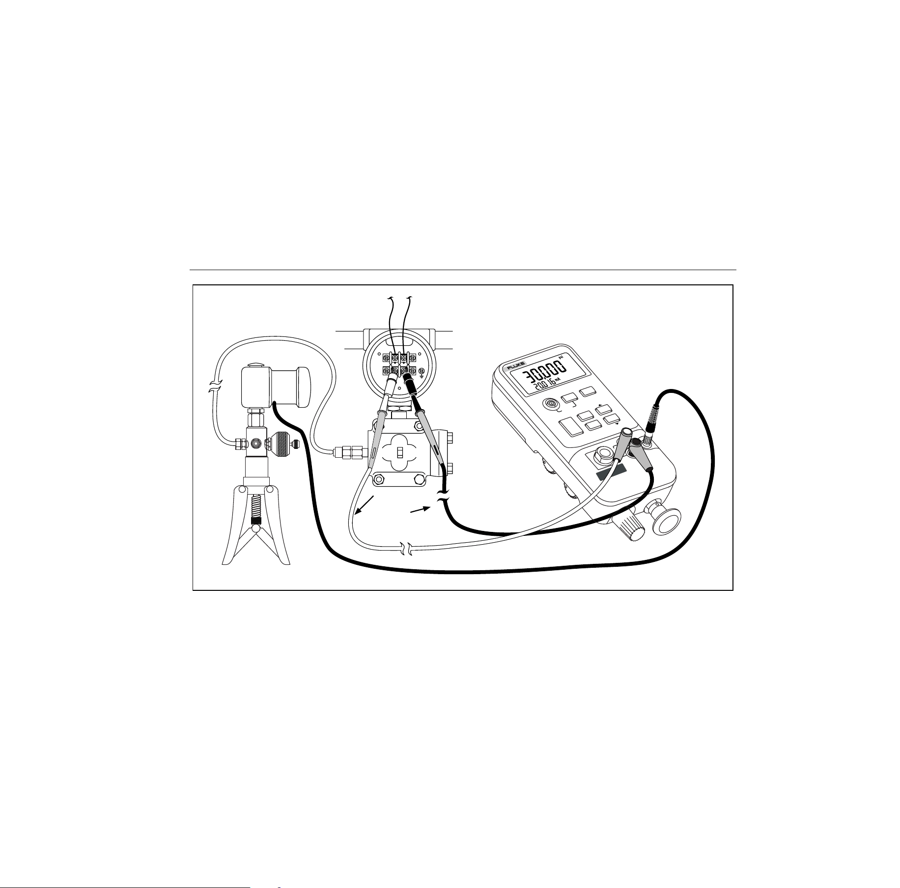
16
Using an External Pump
XW Warning
To avoid damage to the Calibrator and possible
release of pressure, do not connect the internal
sensor to an external pressure source that
exceeds the maximum rated pressure.
To develop higher pressure or vacuum, use an external
pump (such as the Fluke Model 700PTP). Use a Fluke
Pressure Module connected to the pressure module input
on the Calibrator. Pressure modules are listed in Table .
Make overall connections as shown in Figure 6.
Refer to setup and operating instructions included with the
pressure module and pump.
1.888.610.7664 sales@GlobalTestSupply.com
Fluke-Direct
.com
Pressure Calibrator
Using an External Pump
17
mA
MODE
RANGE
O 1 PSI
5 PSI
P
O 7 kP
MIN
MAX
SWITCH
TEST
CO
M
m
A
30V
MAX
0-30psi 0-206kPa
RANGE
SIGNAL
TEST
+
–
Pressure Module
Red
Black
718
PRESSURE
CALIBRATOR
HOLD
UNITS
ZERO
DAMP
HOLD
LOOP
POWER
B
A
R
O
M
ETRIC
ADJ.
MAX
wh006f.eps
Figure 6. Pressure Module with External Pump
1.888.610.7664 sales@GlobalTestSupply.com
Fluke-Direct
.com

718 Series
Users Manual
18
External Fluke Pressure Module
Compatibility
If inappropriate units are selected, the output of Fluke
700P Pressure Modules can cause the Calibrator display
to overflow (OL), or displays values that are too low to be
read. Refer to Table 7 for appropriate unit and range
compatibility.
Table 7. Fluke Pressure Module Compatibility
Pressure Unit Module Compatibility
psi Available on all pressure ranges
inH
2
0 All ranges through 3000 psi
cmH
2
0 All ranges through 1000 psi
bar 15 psi and above
mbar All ranges through 1000 psi
kPa Available on all pressure ranges
inHg Available on all pressure ranges
mmHg All ranges through 1000 psi
kg/cm
2
15 psi and above
1.888.610.7664 sales@GlobalTestSupply.com
Fluke-Direct
.com

Pressure Calibrator
Sourcing Loop Voltage
19
Sourcing Loop Voltage
The Calibrator can supply loop power at 24 V dc to a
current transmitter that is disconnected from the system.
Use the following procedure:
1. With power off, hold down
U
while pressing
O
on. The “Loop Power” icon appears in the display.
2. With the transmitter disconnected from normal loop
power, connect the Calibrator mA (+) and COM (-)
test leads in series with the instrument current loop as
shown in Figure 7.
3. Measure loop current in the mA display.
4. Press
O off to deactivate the 24 V dc supply when
you are done sourcing loop voltage.
In addition to mA, the current can be displayed in two
alternative modes:
• Percent Mode- The current is displayed as a
percentage based on a 4-20 mA scale.
• Percent Error Mode- Transmitter current output error
is displayed. Error is calculated based on a
configurable zero and span pressure and a 4-20 mA
scale.
1. Measure loop current in the mA measurement display.
2. Press
O OFF to deactivate the 24 V dc supply when
you are done sourcing loop voltage.
Percent Error Setup
Press and hold a. After 3 seconds the set icon and 0%
appears on the lower display. Use Wand
X
to adjust the
0% point for the Percent Error calculation, then press
D(ENTER) key to confirm selection. Press a. 100%
is displayed on the lower display. Use Wand
X
to adjust
the 100% point for the Percent Error calculation. Press
D(ENTER) to confirm the selection and to exit.
SIGNAL
TEST
+
–
qo007f.eps
Figure 7. Sourcing Loop Voltage
1.888.610.7664 sales@GlobalTestSupply.com
Fluke-Direct
.com

718 Series
Users Manual
20
Maintenance
XWWarning
To avoid possible electric shock, personal
injury, or sudden release of pressure, review
“Safety Information” earlier in this manual
before proceeding.
Remove test leads before opening.
For maintenance procedures not described in this
instruction sheet, or if the Calibrator needs repair, contact
a Fluke Service Center.
In Case of Difficulty
• Check the battery, test leads, pressure module, and
pressure tubing. Follow replacement and connection
instructions properly.
• Review this instruction sheet to make sure you are
using the Calibrator correctly.
If the Calibrator needs repair, and the Calibrator is under
warranty, see the warranty statement for terms. If the
warranty has lapsed, the Calibrator can be repaired and
returned for a fixed fee.
Cleaning
Periodically wipe the case with a damp cloth and
detergent; do not use abrasives or solvents.
Calibration
Fluke recommends that you calibrate your Calibrator once
a year to ensure that it performs according to its
specifications. A calibration manual is available (PN
686540). Call 1-800-526-4731 from the U.S.A. and
Canada. In other countries, contact a Fluke Service
Center.
1.888.610.7664 sales@GlobalTestSupply.com
Fluke-Direct
.com
Pressure Calibrator
Maintenance
21
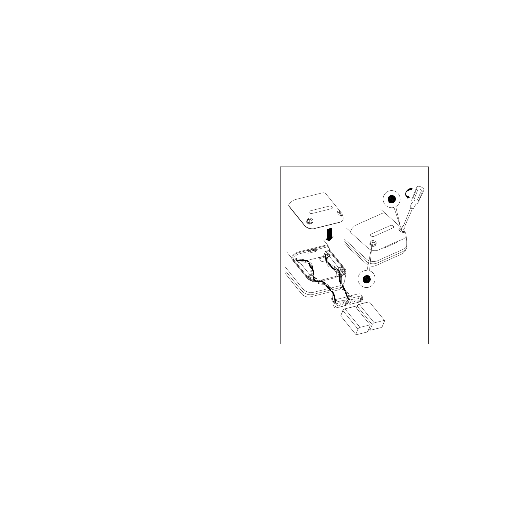
Replacing the Batteries
When the
B
symbol appears on the display, replace
the two 9 V alkaline batteries. Refer to Figure 8.
XW Warning
To avoid false readings, which could lead to
possible electric shock or personal injury,
replace the batteries as soon as the battery
indicator
B
appears.
wh008f.eps
Figure 8. Battery Replacement
1.888.610.7664 sales@GlobalTestSupply.com
Fluke-Direct
.com
718 Series
Users Manual
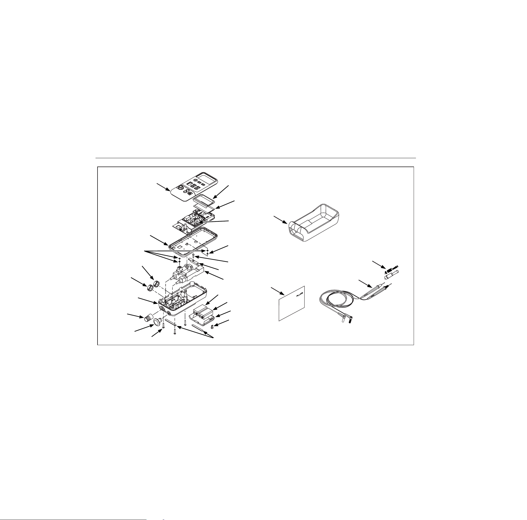
22
Parts and Accessories
Refer to Table 8 and Figure 9.
Table 8. Replacement Parts
Item Description Part/ Mod. No. Qty
AC72
Alligator clip red
Alligator clip black
1670641
1670652
1
1
BT1, BT2 9 V battery, ANSI/NEDA 1604A or IEC 6LR61 614487 2
Holster Holster, Yellow 664182 1
H2, 3, 4 Case screw 832246 3
H5, 6 Battery door fasteners 948609 2
H7, 8 Bracket screw 641131 2
MP1 LCD bezel, 718 30G 664158 1
MP1 LCD bezel, 718 100G 664169 1
MP1 LCD bezel, 718 1G 2545047 1
MP1 LCD bezel, 718 300G 2545058 1
MP2 LCD 686482 1
MP3, 4 Pump retainer bracket 664201 2
MP5 Gasket 664208 1
1G pump 2571725 1
MP6
30G, 100G and 300G pump 2558508 1
MP7, 8 Selector knob 664193 2
MP9 Vernier adjust knob 664190 1
1.888.610.7664 sales@GlobalTestSupply.com
Fluke-Direct
.com

Pressure Calibrator
Parts and Accessories
23
Table 8. Replacement Parts (cont.)
Item Description Part/ Mod. No. Qty
MP10 Pump handle knob 664185 1
MP11, 12, 13 O-ring 146688 3
MP14 Spacer 687449 1
MP85 Case top/connector, 718 1G, 30G, 100G, 300G 2546299 1
MP86 Case bottom 664174 1
MP89, 90 Non-skid foot 885884 2
MP92 Battery door 664177 1
S1 Keypad 2113087 1
TL20 Industrial test lead set 1639457 Opt
TL75 Test lead set 855742 1
TM1 718 Product Overview Manual 1549632 1
- 718 CD-ROM (contains Users Manual) 1574463 1
- 71X Series Calibration Manual 686540 Opt
- Pump (with cleanout) rebuild kit 2553919 Opt
-
718 1G Top Case Decal 2546993 1
-
718 30G Top Case Decal 2547000 1
-
718 100G Top Case Decal 2547017 1
-
718 300G Top Case Decal 2547021 1
1.888.610.7664 sales@GlobalTestSupply.com
Fluke-Direct
.com
718 Series
Users Manual
24
AC72
Alligator Clips
TL75
Test Lead Set
TMI
MP1
H7,8
H2,3,4
H5,6
MP2
S1
Holster
MP85
MP14
MP5
MP7
MP8
MP10
MP9
MP86
MP3,4
MP11,12,13
MP6
MP89,90
BT1
BT2
MP92
wh004f.eps
Figure 9. Replacement Parts
1.888.610.7664 sales@GlobalTestSupply.com
Fluke-Direct
.com

Pressure Calibrator
Specifications
25
Specifications
Specifications are based on a one year calibration cycle
and apply for ambient temperature from +18 °C to +28 °C
unless stated otherwise. “Counts” are the number of
increments or decrements of the least significant digit.
Pressure Sensor Input
Model Range Accuracy
Max Non-
destructive
Pressure
1G -1 to 1 PSI
(-7 to 8 kPa)
5 PSI
(34.5 kPa)
30G -12 to 30 PSI (-
83 to 207 kPa)
60 PSI
(413 kPa)
100G -12 to 100 PSI
(-83 to 690
kPa)
200 PSI
(1.4 mPa)
300G -12 to 300 PSI
(-83 to 2068
kPa)
± 0.05 % of
Range
375 PSI
(2.6 mPa)
Temperature coefficient: 0.01 % of range per
°
C for
temperature ranges -10
°
C to 18
°
C and 28
°
C to 55
°
C
Pressure Module Input
Range Resolution Accuracy
(determined by Pressure Module)
DC mA Input
Range Resolution Accuracy, ±(% of
Reading + Counts)
24 mA 0.001 mA 0.015 + 2
Fuseless overload protection
Temperature coefficient: 0.005 % of range per
°
C for
temperature ranges -10
°
C to 18
°
C and 28
°
C to
55
°
C
Loop Supply
24 V dc nominal
1.888.610.7664 sales@GlobalTestSupply.com
Fluke-Direct
.com

718 Series
Users Manual
26
General Specifications
Maximum voltage applied between either mA terminal
and earth ground or between the mA terminals: 30 V
Storage temperature: -40 °C to 60 °C
Operating temperature: -10 °C to 55 °C
Operating altitude: 3000 meters maximum
Relative humidity: 95 % up to 30 °C, 75 % up to 40 °C,
45 % up to 50 °C, and 35 % up to 55 °C
Vibration: Random 2 g, 5 Hz to 500 Hz per MIL-PRF-
28800F Class 2
Shock: 1 meter drop test, per IEC 61010-1
Safety: Certified as compliant to ISA-82.02.01 (IEC
61010-1 Mod) CSA C22.2 No. 1010.1
Protection Class: Class 2, Double insulated
Power requirements: Two 9 V batteries (ANSI/NEDA
1604A or IEC 6LR61)
Size: 60 mm H x 87 mm W x 210 mm L (2.38 in H x 3.41
in W x 8.28 in L); with holster: 66 mm H x 94 mm W x 216
mm L (2.61 in H x 3.72 in W x 8.5 in L)
Weight: 737 g (26 oz); with holster: 992 g (35 oz)
1.888.610.7664 sales@GlobalTestSupply.com
Fluke-Direct
.com