R&S
®
MXO 5 Series
Oscilloscope
User Manual
1802336902
Version 02
(B2QÓ2)

This manual describes the following R&S
®
MXO 5 models with firmware version 2.0.x.x.
●
R&S
®
MXO54, 4 channels (1802.1008k04)
●
R&S
®
MXO58, 8 channels (1802.1008k08)
© 2023 Rohde & Schwarz
Muehldorfstr. 15, 81671 Muenchen, Germany
Phone: +49 89 41 29 - 0
Email: [email protected]
Internet: www.rohde-schwarz.com
Subject to change – data without tolerance limits is not binding.
R&S
®
is a registered trademark of Rohde & Schwarz GmbH & Co. KG.
The terms HDMI, HDMI High-Definition Multimedia Interface, HDMI trade dress and the HDMI Logos are trademarks or registered
trademarks of HDMI Licensing Administrator, Inc.
All other trademarks are the properties of their respective owners.
1802.3369.02 | Version 02 | R&S
®
MXO 5 Series
Throughout this manual, products from Rohde & Schwarz are indicated without the
®
symbol, e.g. R&S
®
MXO 5 series oscilloscope is
indicated as R&S MXO 5.

Contents
R&S
®
MXO 5 Series
3User Manual 1802.3369.02 ─ 02
Contents
1 Safety and regulatory information......................................................15
1.1 Safety instructions......................................................................................................15
1.2 Labels on the product.................................................................................................20
1.3 Warning messages in the documentation................................................................ 20
1.4 Where to find key documents on Rohde & Schwarz............................................... 21
1.5 Korea certification class A......................................................................................... 21
2 Preface.................................................................................................. 22
2.1 Key features.................................................................................................................22
2.2 Options described in this document.........................................................................22
3 Getting Started..................................................................................... 24
3.1 Preparing for use........................................................................................................ 24
3.1.1 Lifting and carrying........................................................................................................24
3.1.2 Unpacking and checking............................................................................................... 24
3.1.3 Choosing the operating site.......................................................................................... 24
3.1.4 Setting up the product................................................................................................... 25
3.1.5 Considerations for test setup........................................................................................ 27
3.1.6 Connecting to power..................................................................................................... 27
3.1.7 Connecting to LAN........................................................................................................ 28
3.1.8 Connecting external devices......................................................................................... 28
3.1.9 Switching on or off.........................................................................................................29
3.2 Instrument tour............................................................................................................30
3.2.1 Front view......................................................................................................................30
3.2.2 Side view.......................................................................................................................32
3.2.3 Rear view...................................................................................................................... 34
3.2.4 Keys and controls..........................................................................................................35
3.2.5 Checking the functionality............................................................................................. 42
4 Operating the instrument.................................................................... 45
4.1 Means of manual interaction......................................................................................45
4.2 Touchscreen display...................................................................................................46
4.2.1 Information on the display............................................................................................. 46

Contents
R&S
®
MXO 5 Series
4User Manual 1802.3369.02 ─ 02
4.2.2 Control elements on the GUI.........................................................................................49
4.3 Applications.................................................................................................................51
4.4 Working with waveforms............................................................................................52
4.5 Rohde & Schwarz SmartGrid..................................................................................... 54
4.6 Toolbar......................................................................................................................... 56
4.6.1 Using the toolbar........................................................................................................... 56
4.6.2 Configuring the toolbar..................................................................................................56
4.6.3 Toolbar functions........................................................................................................... 57
4.7 Using dialog boxes..................................................................................................... 59
4.8 Entering data............................................................................................................... 60
4.9 Displaying results....................................................................................................... 62
4.10 Adding annotations.................................................................................................... 63
4.11 Information and notifications.....................................................................................65
4.12 Getting user assistance..............................................................................................67
4.12.1 Displaying help..............................................................................................................67
4.12.2 Using help..................................................................................................................... 67
5 Instrument setup..................................................................................69
5.1 System settings...........................................................................................................70
5.1.1 About settings............................................................................................................... 70
5.1.2 Network settings............................................................................................................70
5.1.3 Remote settings............................................................................................................ 73
5.1.4 Localization settings......................................................................................................74
5.1.5 Date and time settings.................................................................................................. 75
5.2 Option settings............................................................................................................76
5.2.1 Software options settings.............................................................................................. 76
5.3 Appearance settings...................................................................................................78
5.3.1 Colors............................................................................................................................78
5.3.2 Grid............................................................................................................................... 80
5.3.3 Dialogs.......................................................................................................................... 82
5.3.4 Peak list.........................................................................................................................83
5.3.5 Miscellaneous............................................................................................................... 84
5.4 Display settings...........................................................................................................84
5.4.1 Persistence settings...................................................................................................... 84

Contents
R&S
®
MXO 5 Series
5User Manual 1802.3369.02 ─ 02
5.4.2 Signal settings...............................................................................................................85
5.4.3 Backlight settings.......................................................................................................... 86
5.5 Front panel settings....................................................................................................87
5.5.1 Hardkeys: function assignment..................................................................................... 87
5.5.2 Knobs............................................................................................................................ 87
5.5.3 LED............................................................................................................................... 88
5.6 Preset setup.................................................................................................................88
5.6.1 Preset settings.............................................................................................................. 89
5.6.2 Factory preset............................................................................................................... 90
5.6.3 Secure erase.................................................................................................................90
5.6.4 Restoring settings......................................................................................................... 91
5.7 Maintenance settings..................................................................................................91
5.7.1 Firmware update........................................................................................................... 91
5.7.2 Alignment...................................................................................................................... 92
5.7.3 Power management...................................................................................................... 94
5.7.4 Service.......................................................................................................................... 94
5.8 Save / recall................................................................................................................. 95
5.8.1 Autonaming................................................................................................................... 95
5.8.2 CSV export....................................................................................................................98
6 Acquisition and waveform setup......................................................100
6.1 Horizontal setup........................................................................................................ 100
6.1.1 About the horizontal system........................................................................................100
6.1.2 Horizontal Setup settings............................................................................................ 101
6.1.3 Zoom settings..............................................................................................................102
6.1.4 Roll mode.................................................................................................................... 102
6.1.5 Reference clock.......................................................................................................... 104
6.2 Acquisition.................................................................................................................104
6.2.1 About the acquisition system...................................................................................... 105
6.2.2 Acquisition Setup settings........................................................................................... 106
6.2.3 Segmentation settings.................................................................................................110
6.2.4 High definition mode.................................................................................................... 111
6.2.5 History settings............................................................................................................112
6.2.6 Speed.......................................................................................................................... 112

Contents
R&S
®
MXO 5 Series
6User Manual 1802.3369.02 ─ 02
6.3 Vertical setup............................................................................................................. 113
6.3.1 About the vertical system............................................................................................ 114
6.3.2 Vertical Setup settings................................................................................................. 114
6.3.3 Bandwidth settings...................................................................................................... 117
6.3.4 Probe settings..............................................................................................................118
6.3.5 Other vertical settings..................................................................................................118
6.4 Probes........................................................................................................................ 119
6.4.1 Common probe settings.............................................................................................. 119
6.4.2 Setup for passive probes............................................................................................ 122
6.4.3 Setup for active voltage probes...................................................................................123
6.4.4 Setup for current probes............................................................................................. 129
6.4.5 Probe info....................................................................................................................131
6.4.6 Adjusting passive probes............................................................................................ 132
7 Trigger.................................................................................................134
7.1 Basics of triggering.................................................................................................. 134
7.1.1 Trigger information...................................................................................................... 135
7.2 Common trigger settings......................................................................................... 135
7.3 Trigger types..............................................................................................................137
7.3.1 Edge trigger.................................................................................................................138
7.3.2 Edge trigger on external trigger source.......................................................................138
7.3.3 Glitch trigger................................................................................................................140
7.3.4 Width trigger................................................................................................................142
7.3.5 Runt trigger................................................................................................................. 143
7.3.6 Window trigger............................................................................................................ 145
7.3.7 Timeout trigger............................................................................................................ 147
7.3.8 Interval trigger............................................................................................................. 148
7.3.9 Slew rate trigger.......................................................................................................... 150
7.3.10 Line trigger.................................................................................................................. 152
7.4 Trigger mode / holdoff.............................................................................................. 152
7.5 Hysteresis.................................................................................................................. 155
7.6 Channel filter............................................................................................................. 156
7.7 Actions on trigger..................................................................................................... 157
8 Waveform analysis.............................................................................160

Contents
R&S
®
MXO 5 Series
7User Manual 1802.3369.02 ─ 02
8.1 Zoom.......................................................................................................................... 160
8.1.1 Zoom settings..............................................................................................................160
8.1.2 Zooming for details......................................................................................................163
8.2 Mathematics.............................................................................................................. 164
8.2.1 Displaying math waveforms........................................................................................ 165
8.2.2 Math waveforms settings............................................................................................ 165
8.2.3 Math filter.................................................................................................................... 168
8.2.4 Math scale settings..................................................................................................... 169
8.3 History........................................................................................................................170
8.3.1 About history............................................................................................................... 170
8.3.2 History setup............................................................................................................... 171
8.3.3 Quick access history dialog.........................................................................................173
8.3.4 Using history............................................................................................................... 174
8.4 Reference waveforms............................................................................................... 176
8.4.1 Working with reference waveforms............................................................................. 176
8.4.2 Settings for reference waveforms............................................................................... 177
9 Measurements....................................................................................184
9.1 Cursor measurements.............................................................................................. 184
9.1.1 Cursors and results of cursor measurements............................................................. 184
9.1.2 Using cursors.............................................................................................................. 185
9.1.3 Settings for cursor measurements.............................................................................. 187
9.2 Automatic measurements........................................................................................ 193
9.2.1 Measurement results...................................................................................................196
9.2.2 Gate settings for measurements................................................................................. 197
9.2.3 Reference level........................................................................................................... 199
9.2.4 Measurement types.....................................................................................................202
9.2.5 Settings for measurements......................................................................................... 204
9.2.6 Statistics...................................................................................................................... 211
9.2.7 Track........................................................................................................................... 213
10 Spectrum analysis............................................................................. 218
10.1 Fundamentals of spectrum analysis....................................................................... 218
10.2 Configuring spectrum waveforms...........................................................................220
10.3 Spectrum setup......................................................................................................... 222

Contents
R&S
®
MXO 5 Series
8User Manual 1802.3369.02 ─ 02
10.4 Spectrum scale..........................................................................................................225
10.5 Spectrum gate........................................................................................................... 226
10.6 Spectrum peak list.................................................................................................... 227
11 Applications........................................................................................231
11.1 Frequency response analysis (option R&S MXO5-K36)........................................ 231
11.1.1 About the frequency response analysis plot............................................................... 232
11.1.2 Using a frequency response analysis......................................................................... 233
11.1.3 Settings for frequency response analysis................................................................... 234
11.1.4 FRA saving results...................................................................................................... 244
11.1.5 Dependencies of the measurement setup.................................................................. 245
11.2 Power analysis (option R&S MXO5-K31)................................................................ 246
11.2.1 Power measurement selection....................................................................................246
11.2.2 Power measurements................................................................................................. 248
11.2.3 Reference level........................................................................................................... 259
11.2.4 Deskew....................................................................................................................... 261
11.2.5 Offset compensation................................................................................................... 262
11.3 Digital voltmeter........................................................................................................ 263
11.3.1 Using the digital voltmeter...........................................................................................263
11.3.2 Settings of the digital voltmeter................................................................................... 264
12 Data and file management.................................................................266
12.1 Save and recall user settings...................................................................................267
12.1.1 Using savesets............................................................................................................267
12.1.2 Gen saveset................................................................................................................ 269
12.2 Save and recall waveform data................................................................................271
12.2.1 Waveform settings.......................................................................................................271
12.2.2 Saving waveforms.......................................................................................................273
12.2.3 Waveform export files..................................................................................................274
12.3 Saving results............................................................................................................279
12.4 Screenshots...............................................................................................................280
12.4.1 Screenshot settings.....................................................................................................281
12.4.2 Configuring and saving screenshots........................................................................... 283
12.5 File browser dialog................................................................................................... 283

Contents
R&S
®
MXO 5 Series
9User Manual 1802.3369.02 ─ 02
13 Protocol analysis............................................................................... 285
13.1 Basics of protocol analysis......................................................................................285
13.1.1 Setup - general settings.............................................................................................. 286
13.1.2 Advanced.................................................................................................................... 288
13.1.3 Display........................................................................................................................ 288
13.1.4 Filter............................................................................................................................ 289
13.1.5 Trigger......................................................................................................................... 289
13.1.6 Shortcuts..................................................................................................................... 290
13.1.7 Export protocol results................................................................................................ 291
13.1.8 Bit pattern editor..........................................................................................................292
13.2 SPI bus (option R&S MXO5-K510)........................................................................... 293
13.2.1 About the SPI protocol................................................................................................ 293
13.2.2 SPI configuration.........................................................................................................294
13.2.3 SPI filter.......................................................................................................................298
13.2.4 SPI trigger................................................................................................................... 301
13.2.5 SPI decode results...................................................................................................... 303
13.2.6 Performing SPI decoding............................................................................................ 305
13.3 I²C (option R&S MXO5-K510)................................................................................... 309
13.3.1 About the I²C protocol................................................................................................. 309
13.3.2 I²C configuration.......................................................................................................... 311
13.3.3 I2C filter.......................................................................................................................314
13.3.4 I²C trigger settings.......................................................................................................316
13.3.5 I²C decode results....................................................................................................... 320
13.3.6 Performing I2C decoding............................................................................................ 322
13.4 UART (option R&S MXO5-K510).............................................................................. 326
13.4.1 About the UART / RS-232 interface............................................................................ 326
13.4.2 UART configuration.....................................................................................................327
13.4.3 UART filter...................................................................................................................331
13.4.4 UART trigger............................................................................................................... 333
13.4.5 UART decode results.................................................................................................. 335
13.4.6 Performing UART decoding........................................................................................ 336
13.5 CAN (option R&S MXO5-K520)................................................................................ 340
13.5.1 CAN configuration....................................................................................................... 340

Contents
R&S
®
MXO 5 Series
10User Manual 1802.3369.02 ─ 02
13.5.2 CAN filter.....................................................................................................................346
13.5.3 CAN trigger settings.................................................................................................... 349
13.5.4 CAN decode results.................................................................................................... 358
13.5.5 Performing CAN decoding.......................................................................................... 360
13.6 LIN (option R&S MXO5-K520).................................................................................. 365
13.6.1 LIN configuration......................................................................................................... 366
13.6.2 LIN trigger settings...................................................................................................... 368
13.6.3 LIN filter.......................................................................................................................370
13.6.4 LIN decode results...................................................................................................... 373
13.6.5 Performing LIN decoding............................................................................................ 375
14 Mixed signal option (MSO, R&S MXO5-B1)..................................... 378
14.1 Logic configuration...................................................................................................378
14.1.1 Setup...........................................................................................................................378
14.1.2 Bus.............................................................................................................................. 381
14.1.3 Label settings.............................................................................................................. 382
14.1.4 Skew settings.............................................................................................................. 383
14.2 Display....................................................................................................................... 384
14.2.1 Logic bus - decode table............................................................................................. 385
15 Waveform generator (option R&S MXO5-B6).................................. 386
15.1 Setup of the waveform generator............................................................................ 386
15.1.1 General settings.......................................................................................................... 386
15.1.2 Modulation settings..................................................................................................... 394
15.1.3 Sweep settings............................................................................................................397
15.1.4 Arbitrary waveforms.................................................................................................... 398
15.2 Synchronize settings................................................................................................ 402
15.3 Configuring the waveform generator...................................................................... 403
15.3.1 Configuring a function waveform.................................................................................403
15.3.2 Configuring a modulation waveform............................................................................403
15.3.3 Configuring a sine sweep waveform........................................................................... 405
15.3.4 Configuring an arbitrary waveform.............................................................................. 405
16 Network operation and remote control............................................ 407
16.1 Connecting the instrument to the network (LAN).................................................. 407

Contents
R&S
®
MXO 5 Series
11User Manual 1802.3369.02 ─ 02
16.1.1 Connecting the instrument to the network...................................................................408
16.1.2 Assigning the IP address............................................................................................ 408
16.1.3 Using host names....................................................................................................... 409
16.2 Web interface.............................................................................................................410
16.2.1 Settings on the R&S MXO 5........................................................................................410
16.2.2 Web browser............................................................................................................... 410
16.3 Remote operation with VNC client.......................................................................... 415
16.4 Remote control..........................................................................................................415
16.4.1 Remote control interfaces and protocols.....................................................................415
16.4.2 Starting and stopping remote control.......................................................................... 417
16.5 Remote control - status reporting system..............................................................418
16.5.1 Hierarchy of status registers....................................................................................... 418
16.5.2 Structure of a SCPI status register..............................................................................420
16.5.3 Contents of the status registers.................................................................................. 421
16.5.4 Error queue................................................................................................................. 426
16.5.5 Reset values of the status reporting system............................................................... 426
17 Remote control commands...............................................................428
17.1 Conventions used in remote command description............................................. 428
17.2 Finding the appropriate command.......................................................................... 429
17.3 Frequently used parameters and suffixes.............................................................. 429
17.3.1 Waveform parameter...................................................................................................429
17.3.2 Slope parameter..........................................................................................................430
17.3.3 Polarity parameter.......................................................................................................430
17.4 Programming examples........................................................................................... 430
17.4.1 SmartGrid layout with zoom........................................................................................ 430
17.4.2 Saving screenshots to file........................................................................................... 434
17.4.3 Data transfer in roll mode............................................................................................435
17.5 Common commands.................................................................................................435
17.6 General remote settings........................................................................................... 439
17.7 Instrument setup....................................................................................................... 441
17.7.1 System........................................................................................................................ 441
17.7.2 SmartGrid....................................................................................................................443
17.7.3 Toolbar........................................................................................................................ 448

Contents
R&S
®
MXO 5 Series
12User Manual 1802.3369.02 ─ 02
17.7.4 Appearance.................................................................................................................449
17.7.5 Display........................................................................................................................ 453
17.7.6 Maintenance................................................................................................................459
17.8 Acquisition and setup...............................................................................................460
17.8.1 Starting and stopping acquisition................................................................................ 460
17.8.2 Horizontal setup.......................................................................................................... 461
17.8.3 Roll mode.................................................................................................................... 463
17.8.4 Vertical setup...............................................................................................................464
17.8.5 Waveform data export................................................................................................. 469
17.8.6 Acquisition setup......................................................................................................... 471
17.8.7 Fast segmentation.......................................................................................................476
17.8.8 Probes.........................................................................................................................476
17.8.9 High definition mode................................................................................................... 490
17.8.10 Reference clock.......................................................................................................... 491
17.9 Trigger........................................................................................................................ 492
17.9.1 Common trigger settings............................................................................................. 493
17.9.2 Edge trigger.................................................................................................................494
17.9.3 Glitch trigger................................................................................................................497
17.9.4 Width trigger................................................................................................................498
17.9.5 Runt trigger................................................................................................................. 499
17.9.6 Window trigger............................................................................................................ 502
17.9.7 Timeout trigger............................................................................................................ 505
17.9.8 Interval trigger............................................................................................................. 506
17.9.9 Slew rate trigger.......................................................................................................... 507
17.9.10 Trigger mode, holdoff.................................................................................................. 510
17.9.11 Hysteresis................................................................................................................... 513
17.9.12 Channel filter............................................................................................................... 515
17.9.13 Actions on trigger........................................................................................................ 516
17.10 Waveform analysis....................................................................................................518
17.10.1 Zoom........................................................................................................................... 518
17.10.2 Mathematics................................................................................................................526
17.10.3 History......................................................................................................................... 531
17.10.4 Reference waveforms................................................................................................. 534

Contents
R&S
®
MXO 5 Series
13User Manual 1802.3369.02 ─ 02
17.11 Data management..................................................................................................... 543
17.11.1 Instrument settings......................................................................................................543
17.11.2 Saveset....................................................................................................................... 550
17.11.3 Gen saveset................................................................................................................ 550
17.11.4 Waveform export to file............................................................................................... 550
17.11.5 Results........................................................................................................................ 553
17.11.6 Screenshots................................................................................................................ 554
17.12 Automatic measurements........................................................................................ 557
17.12.1 General settings.......................................................................................................... 557
17.12.2 Measurement-specific settings....................................................................................560
17.12.3 Results........................................................................................................................ 563
17.12.4 Statistics......................................................................................................................566
17.12.5 Gate............................................................................................................................ 568
17.12.6 Reference levels......................................................................................................... 571
17.12.7 Tracks..........................................................................................................................575
17.13 Cursor measurements.............................................................................................. 577
17.13.1 Cursor setup................................................................................................................578
17.13.2 Cursor results..............................................................................................................584
17.13.3 Peak search using cursors..........................................................................................585
17.13.4 Cursor appearance..................................................................................................... 587
17.14 Spectrum analysis.................................................................................................... 588
17.14.1 Spectrum setup........................................................................................................... 588
17.14.2 Spectrum gate.............................................................................................................596
17.14.3 Peak list.......................................................................................................................597
17.14.4 Data export of spectrum waveforms........................................................................... 601
17.15 Applications...............................................................................................................603
17.15.1 Frequency response analysis (option R&S MXO5-K36)............................................. 603
17.15.2 Power analysis (option R&S MXO5-K31)....................................................................618
17.15.3 Digital voltmeter.......................................................................................................... 641
17.16 Protocols....................................................................................................................644
17.16.1 Configuration settings for all serial protocols.............................................................. 644
17.16.2 SPI (option R&S MXO5-K510).................................................................................... 648
17.16.3 I²C (option R&S MXO5-K510)..................................................................................... 666

Contents
R&S
®
MXO 5 Series
14User Manual 1802.3369.02 ─ 02
17.16.4 UART / RS-232 (option R&S MXO5-K510).................................................................685
17.16.5 CAN (option R&S MXO5-K520).................................................................................. 700
17.16.6 LIN (option R&S MXO5-K520).................................................................................... 733
17.17 Mixed signal option (option R&S MXO5-B1)...........................................................749
17.17.1 Digital channels...........................................................................................................749
17.17.2 Logic configuration...................................................................................................... 752
17.17.3 MSO data.................................................................................................................... 759
17.18 Waveform generator (option R&S MXO5-B6)......................................................... 761
17.18.1 Waveform generator setup..........................................................................................762
17.18.2 Synchronize settings................................................................................................... 779
17.19 Status reporting........................................................................................................ 780
17.19.1 General commands.....................................................................................................781
17.19.2 STATus:OPERation register........................................................................................781
17.19.3 STATus:QUEStionable registers................................................................................. 782
17.19.4 Reading out the CONDition part................................................................................. 784
17.19.5 Reading out the EVENt part........................................................................................785
17.19.6 Controlling the ENABle part........................................................................................ 785
17.19.7 Controlling the negative transition part........................................................................786
17.19.8 Controlling the positive transition part......................................................................... 787
17.19.9 Programming tips and examples.................................................................................788
18 Maintenance and support..................................................................791
18.1 Cleaning..................................................................................................................... 791
18.2 Changing fuses......................................................................................................... 791
18.3 Contacting customer support..................................................................................791
18.4 Information for technical support............................................................................792
18.5 Data security..............................................................................................................792
18.6 Transporting.............................................................................................................. 793
18.7 Storage.......................................................................................................................793
18.8 Disposal..................................................................................................................... 793
List of commands.............................................................................. 795
Index....................................................................................................820

Safety and regulatory information
R&S
®
MXO 5 Series
15User Manual 1802.3369.02 ─ 02
1 Safety and regulatory information
The product documentation helps you to use the product safely and efficiently.
Where do I find safety information?
Safety information is part of the product documentation. It warns you of potential dan-
gers and gives instructions on how to prevent personal injury or damage caused by
dangerous situations. Safety information is provided as follows:
●
In Chapter 1.1, "Safety instructions", on page 15. The same information is provi-
ded in many languages in printed format. The printed "Safety Instructions for Oscil-
loscopes and Accessories" are delivered with the product.
●
Throughout the documentation, safety instructions are provided when you need to
take care during setup or operation.
Intended use
The R&S MXO 5 oscilloscope is designed for measurements on circuits that are only
indirectly connected to the mains or not connected at all. It is not rated for any mea-
surement category.
The product is intended for the development, production and verification of electronic
components and devices in industrial, administrative, and laboratory environments.
Use the product only for its designated purpose. Observe the operating conditions and
performance limits stated in the data sheet.
1.1 Safety instructions
Products from the Rohde & Schwarz group of companies are manufactured according
to the highest technical standards. To use the products safely, follow the instructions
provided here and in the product documentation. Keep the product documentation
nearby and offer it to other users.
Use the product only for its intended use and within its performance limits. Intended
use and limits are described in the product documentation such as the data sheet,
manuals and the printed "Safety Instructions for Oscilloscopes and Accessories" docu-
ment. If you are unsure about the appropriate use, contact Rohde & Schwarz customer
service.
Using the product requires specialists or specially trained personnel. These users also
need sound knowledge of at least one of the languages in which the user interfaces
and the product documentation are available.
Reconfigure or adjust the product only as described in the product documentation or
the data sheet. Any other modifications can affect safety and are not permitted.
Never open the casing of the product. Only service personnel authorized by
Rohde & Schwarz are allowed to repair the product. If any part of the product is dam-
aged or broken, stop using the product. Contact Rohde & Schwarz customer service at
https://www.rohde-schwarz.com/support.
Safety instructions

Safety and regulatory information
R&S
®
MXO 5 Series
16User Manual 1802.3369.02 ─ 02
In these safety instructions, the term "product" covers instruments (oscilloscopes),
probes and their accessories.
Lifting and carrying the instrument
Check the data sheet for the maximum weight of the instrument. A single person can
only carry a maximum of 18 kg safely depending on age, gender and physical condi-
tion. If your instrument is heavier than 18 kg, do not move or carry it by yourself.
Use the instrument handles to move or carry the instrument. Do not use the mounted
accessories instead of the handles. Accessories are not designed to carry the weight
of the instrument.
To move the instrument safely, you can use lifting or transporting equipment such as lift
trucks and forklifts. Follow the instructions provided by the equipment manufacturer.
Choosing the operating site
Only use the product indoors. The product casing is not waterproof. Water that enters
can electrically connect the casing with live parts, which can lead to electric shock,
serious personal injury or death if you touch the casing. If Rohde & Schwarz provides
accessories designed for outdoor use of your product, e.g. a protective cover, you can
use the product outdoors.
Unless otherwise specified in the data sheet, you can operate the product up to an alti-
tude of 2000 m above sea level.
The product is suitable for pollution degree 2 environments where nonconductive con-
tamination can occur. For more information on environmental conditions such as ambi-
ent temperature and humidity, see the data sheet.
Setting up the product
Always place the product on a stable, flat and level surface with the bottom of the prod-
uct facing down. If the product is designed for different positions, secure the product so
that it cannot fall over.
If the product has foldable feet, always fold the feet completely in or out to ensure sta-
bility. The feet can collapse if they are not folded out completely or if the product is
moved without lifting it. The foldable feet are designed to carry the weight of the prod-
uct, but not an extra load.
If stacking is possible, keep in mind that a stack of products can fall over and cause
injury.
If you mount products in a rack, ensure that the rack has sufficient load capacity and
stability. Observe the specifications of the rack manufacturer. Always install the prod-
ucts from the bottom shelf to the top shelf so that the rack stands securely. Secure the
product so that it cannot fall off the rack.
Connecting the product
Unless specified otherwise in the data sheet, only connect the interfaces and measure-
ment ports of the product to other products or circuits that have double or reinforced
Safety instructions

Safety and regulatory information
R&S
®
MXO 5 Series
17User Manual 1802.3369.02 ─ 02
insulation to protect against dangerous live voltages. This protective measure against
electric shock is known as SELV (safety extra-low voltage).
Connecting to power and grounding
The mains power supply input of the instrument complies with overvoltage category II.
Connect the product to a fixed installation used to supply energy-consuming equipment
such as household appliances and similar loads. Keep in mind that electrically pow-
ered products have risks, such as electric shock, fire, personal injury or even death.
Take the following measures for your safety:
●
Do not use an isolating transformer to connect the instrument to the mains power
supply.
●
Before switching on the product, ensure that the voltage and frequency indicated
on the product match the available power source. If the power adapter does not
adjust automatically, set the correct value and check the rating of the fuse.
●
If a product has an exchangeable fuse, its type and characteristics are indicated
next to the fuse holder. Before changing the fuse, switch off the product and dis-
connect it from the power source. How to change the fuse is described in the prod-
uct documentation.
●
Only use the power cable delivered with the product. It complies with country-spe-
cific safety requirements. Only insert the plug into an outlet with protective conduc-
tor terminal.
●
Only use intact cables and route them carefully so that they cannot be damaged.
Check the power cables regularly to ensure that they are undamaged. Also ensure
that nobody can trip over loose cables.
●
If you connect the product to an external power supply, use the one delivered with
the product or recommended in the product documentation. The external power
supply must conform to the country-specific regulations.
●
Ensure that you can disconnect the product from the power source at any time.
Pull the power plug to disconnect the product. The power plug must be easily
accessible. If the product is integrated into a system that does not meet these
requirements, provide an easily accessible circuit breaker at the system level.
●
Replace parts that are relevant to safety only by original parts, e.g. power cables or
fuses.
Performing measurements
Take the following measures for your safety:
●
To ascertain voltage-free state, use an appropriate voltage tester. Any measure-
ment setup including an oscilloscope is not suitable for this purpose.
●
The maximum input voltage on channel inputs and the external trigger input must
not exceed the value specified in the data sheet.
●
Observe all voltage and current ratings of the instrument, the probes, and the
accessories. Exceeding the allowed voltages can lead to an electric shock.
Limits and ratings are marked on the products and listed in the data sheets.
Consider that the rated voltage depends on the frequency. The voltage limitation
curves or values are provided in the data sheet.
Safety instructions

Safety and regulatory information
R&S
®
MXO 5 Series
18User Manual 1802.3369.02 ─ 02
●
Never cause any short circuits when measuring sources with high output currents.
●
Use only probes and accessories that comply with the measurement category
(CAT) of your measurement task. If the product is rated for any measurement cate-
gory, the permitted category is indicated on the product and in the data sheet. If
you use other than Rohde & Schwarz accessories, make sure that they are suita-
ble for the instrument and the measurement task.
●
Set the correct attenuation factor on the instrument according to the probe being
used. Otherwise, the measurement results do not reflect the actual voltage level,
and you might misjudge the actual risk.
●
When working with high voltages and current probes, observe the additional oper-
ating conditions specified in these safety instructions.
●
The probe pins are extremely pointed and can easily penetrate clothes and the
skin. Handle the probe pins with great care. To exchange a probe pin, use tweez-
ers or pliers to avoid injuries. When transporting the accessories, always use the
box supplied with the probe.
●
Prevent the probe from receiving mechanical shock. Avoid putting excessive strain
on the probe cable or exposing it to sharp bends. Touching a broken cable during
measurements can cause injuries.
●
Set up all probe connections to the instrument before applying power.
Working with hazardous voltages
Voltages higher than 30 V RMS, or 42 V peak, or 60 V DC are regarded as hazardous
contact voltages. Direct contact with them can cause serious injuries.
Make sure that only electrically skilled persons use the products for measurements on
hazardous contact voltages. These working conditions require special education and
experience to perceive risks and to avoid hazards which electricity can create.
When working with hazardous contact voltages, use protective measures to preclude
direct contact with the measurement setup:
●
Do not touch exposed connections and components when power is applied.
●
Switch off the test circuit while connecting and disconnecting probe leads.
●
Use only insulated voltage probes, test leads and adapters.
●
Make sure that the input leads fulfill the safety requirements for your measurement.
The delivered input leads might have a jacket wear indicator that indicates a worn
jacket by different jacket color. In this case, do not use the input lead. Replace it
with a new one.
●
When connecting to the DUT, keep your fingers behind finger guard. Remove jew-
elry, watches, and other metallic objects. Only use 4 mm safety banana plugs.
Working with current probes
When working with current probes, you can measure high-frequency currents or cur-
rents that contain high-frequency components.
●
Switch off the test circuit while connecting the probe.
Safety instructions

Safety and regulatory information
R&S
®
MXO 5 Series
19User Manual 1802.3369.02 ─ 02
●
Do not attach the clamp to bare unisolated conductors. To avoid injury from a short
circuit, measure at a location on an insulated wire where the insulation is sufficient
for the circuit voltage.
●
Connect the probe only to the secondary side of a breaker. With this measure, you
avoid injury, if a short circuit occurs.
●
The following effects can cause burns and fire or damage to the measurement site:
– Eddy current loss can cause heating of the sensor head.
– Dielectric heating can cause heating of cord insulation and other materials.
●
When measuring current that includes a high-frequency component, consider the
derating characteristics of the probe. Do not measure any current that exceeds the
rated current.
●
Using the probes with high frequencies or strong magnetic fields may cause the
device to become abnormally hot, resulting in fire, equipment damage, or burns.
Measurement categories
IEC 61010-2-030 defines measurement categories that rate instruments on their ability
to resist short transient overvoltages that occur in addition to the working voltage. Use
the measurement setup only in electrical environments for which they are rated.
●
0 - Instruments without rated measurement category
For measurements performed on circuits not directly connected to mains, for exam-
ple, electronics, circuits powered by batteries, and specially protected secondary
circuits. This measurement category is also known as CAT I.
●
CAT II:
For measurements performed on circuits directly connected to the low-voltage
installation by a standard socket outlet, for example, household appliances and
portable tools.
●
CAT III:
For measurements performed in the building installation, such as junction boxes,
circuit breakers, distribution boards, and equipment with permanent connection to
the fixed installation.
●
CAT IV:
For measurements performed at the source of the low-voltage installation, such as
electricity meters and primary overcurrent protection devices.
Safety instructions
Safety and regulatory information
R&S
®
MXO 5 Series
20User Manual 1802.3369.02 ─ 02
Cleaning the product
Use a dry, lint-free cloth to clean the product. When cleaning, keep in mind that the
casing is not waterproof. Do not use liquid cleaning agents.
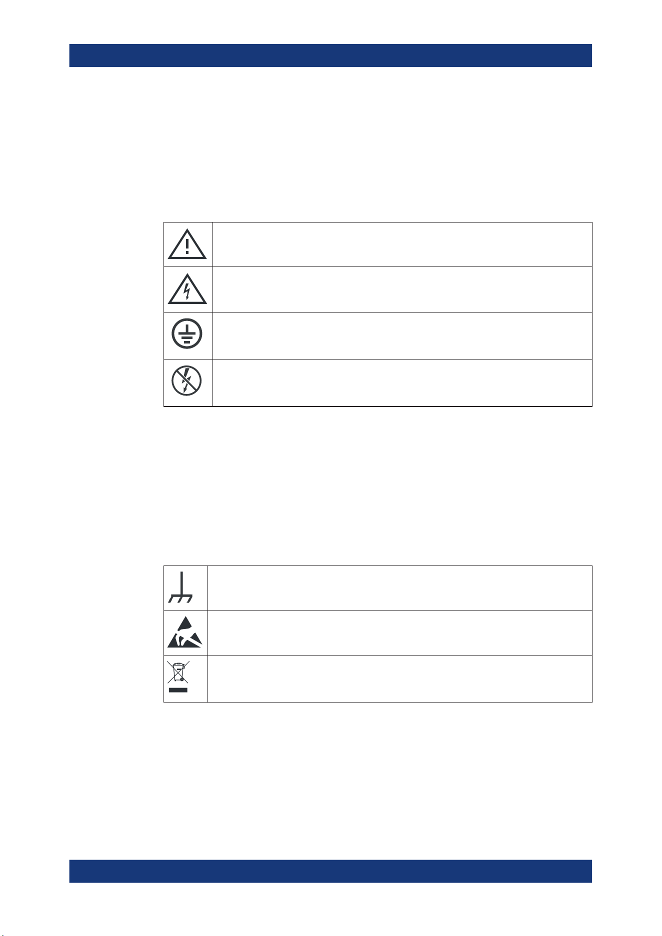
Meaning of safety labels
Safety labels on the product warn against potential hazards.
Potential hazard
Read the product documentation to avoid personal injury or product damage.
Electrical hazard
Indicates live parts. Risk of electric shock, fire, personal injury or even death.
Protective conductor terminal
Connect this terminal to a grounded external conductor or to protective ground. This connec-
tion protects you against electric shock if an electric problem occurs.
Hazardous contact voltages
Do not use the probe at uninsulated live lines. Make sure to measure at sufficiently insulated
conductors. This measure protects you against electric shock, electric burn, or arc flash.
1.2 Labels on the product
Labels on the casing inform about:
●
Personal safety, see "Meaning of safety labels" on page 20
●
Product and environment safety, see Table 1-1
●
Identification of the product
Table 1-1: Labels regarding product and environment safety
Chassis grounding terminal
Take care when handling electrostatic sensitive devices.
Labeling in line with EN 50419 for disposal of electrical and electronic equipment after the prod-
uct has come to the end of its service life.
For more information, see "Disposing of electrical and electronic equipment" on page 793.
1.3 Warning messages in the documentation
A warning message points out a risk or danger that you need to be aware of. The sig-
nal word indicates the severity of the safety hazard and how likely it will occur if you do
not follow the safety precautions.
Warning messages in the documentation

Safety and regulatory information
R&S
®
MXO 5 Series
21User Manual 1802.3369.02 ─ 02
WARNING
Potentially hazardous situation. Could result in death or serious injury if not avoided.
CAUTION
Potentially hazardous situation. Could result in minor or moderate injury if not avoided.
NOTICE
Potential risks of damage. Could result in damage to the supported product or to other
property.
1.4 Where to find key documents on Rohde & Schwarz
Certificates issued to Rohde & Schwarz that are relevant for your country are provided
at www.rohde-schwarz.com/key-documents, e.g. concerning:
●
Quality management
●
Environmental management
●
Information security management
●
Accreditations
1.5 Korea certification class A
이 기기는 업무용(A급) 전자파 적합기기로서 판매자 또는 사용자는 이 점을 주의하시기
바라며, 가정외의 지역에서 사용하는 것을 목적으로 합니다.
Korea certification class A

Preface
R&S
®
MXO 5 Series
22User Manual 1802.3369.02 ─ 02
2 Preface
2.1 Key features
The R&S MXO 5 series oscilloscope is a next generation oscilloscope with 4 or 8 chan-
nels, evolved for more challenges.
Using the R&S MXO 5, you can:
●
Acquire, process and display signals with unrivaled speed.
●
Detect signal details, faults and anomalies instantly.
●
Increase your statistical confidence.
The R&S MXO 5 series oscilloscopes utilize advanced technologies:
●
Fastest update rate of up to 4.5 million waveforms/s thanks to MXO-EP ASIC
●
12 bit ADC at all sample rates, and 18 bit vertical resolution in HD mode
●
Bandwidth up to 2 GHz, and up to 5 Gsample/s sample rate
●
Deepest standard memory: 500 Mpoints per channel
●
High-precision digital trigger with best-in-class trigger jitter, also available in HD
mode
●
Nearly zero blind time: up to 99% real-time signal activity capture
●
Lowest measurement noise
●
Eco-friendly design: low power consumption, automatic power-up capability,
scarcely audible
Features and applications help achieve fast and accurate results, for example:
●
Segmented memory & history mode to analyze previous acquisitions
●
Superior spectrum analysis with 45 000 FFT/s, which allows capture of spurious
spectrum events
4 simultaneous spectrums with independent time and frequency control
●
Integrated arbitrary waveform generator
●
Logic analysis with 16 digital channels
●
Dual-path serial protocol analysis
●
Frequency response analysis (Bode plots)
●
Large high-resolution touchscreen, R&S SmartGrid, configurable toolbar, intuitive
navigation
●
Wide selection of compatible probes
2.2 Options described in this document
In addition to the base unit, the following options are described in this documentation:
Options described in this document

Preface
R&S
®
MXO 5 Series
23User Manual 1802.3369.02 ─ 02
Type Designation Order No.
R&S MXO5-B1 MSO
R&S MXO5-B6 Waveform and pattern generator 1802.0753.02
R&S MXO5-K31 Power analysis 1802.0799.02
R&S MXO5-K36 Frequency response analysis 1802.1943.02
R&S MXO5-K510 Triggering and decoding low
speed serial buses:
I2C, SPI, UART/RS-232/RS-422/
RS-485
1802.1243.02
R&S MXO5-K520 Triggering and decoding automo-
tive protocols:
LIN, CAN, CAN FD, CAN XL
1802.1920.02
Options described in this document

Getting Started
R&S
®
MXO 5 Series
24User Manual 1802.3369.02 ─ 02
3 Getting Started
3.1 Preparing for use
Here, you can find basic information about setting up the instrument for the first time or
when changing the operating site.
3.1.1 Lifting and carrying
See: "Lifting and carrying the instrument" on page 16.
3.1.2 Unpacking and checking
1. Unpack the product carefully.
2. Retain the original packing material. Use it when transporting or shipping the prod-
uct later.
3. Using the delivery notes, check the equipment for completeness.
4. Check the equipment for damage.
If the delivery is incomplete or equipment is damaged, contact Rohde & Schwarz.
3.1.3 Choosing the operating site
Specific operating conditions ensure proper operation and avoid damage to the prod-
uct and connected devices. For information on environmental conditions such as ambi-
ent temperature and humidity, see the data sheet.
For safety information, see "Choosing the operating site" on page 16.
Electromagnetic compatibility classes
The electromagnetic compatibility (EMC) class indicates where you can operate the
product. The EMC class of the product is given in the data sheet.
●
Class B equipment is suitable for use in:
– Residential environments
– Environments that are directly connected to a low-voltage supply network that
supplies residential buildings
●
Class A equipment is intended for use in industrial environments. It can cause
radio disturbances in residential environments due to possible conducted and radi-
ated disturbances. It is therefore not suitable for class B environments.
Preparing for use
Getting Started
R&S
®
MXO 5 Series
25User Manual 1802.3369.02 ─ 02
If class A equipment causes radio disturbances, take appropriate measures to
eliminate them.
3.1.4 Setting up the product
When setting up the instrument, follow the safety instructions:
●
"Setting up the product" on page 16
●
"Intended use" on page 15
3.1.4.1 Placing the product on a bench top
For standalone operation, place the instrument on a horizontal bench with even, flat
surface. The instrument can be used in horizontal position, standing on its feet, or with
the support feet on the bottom extended.
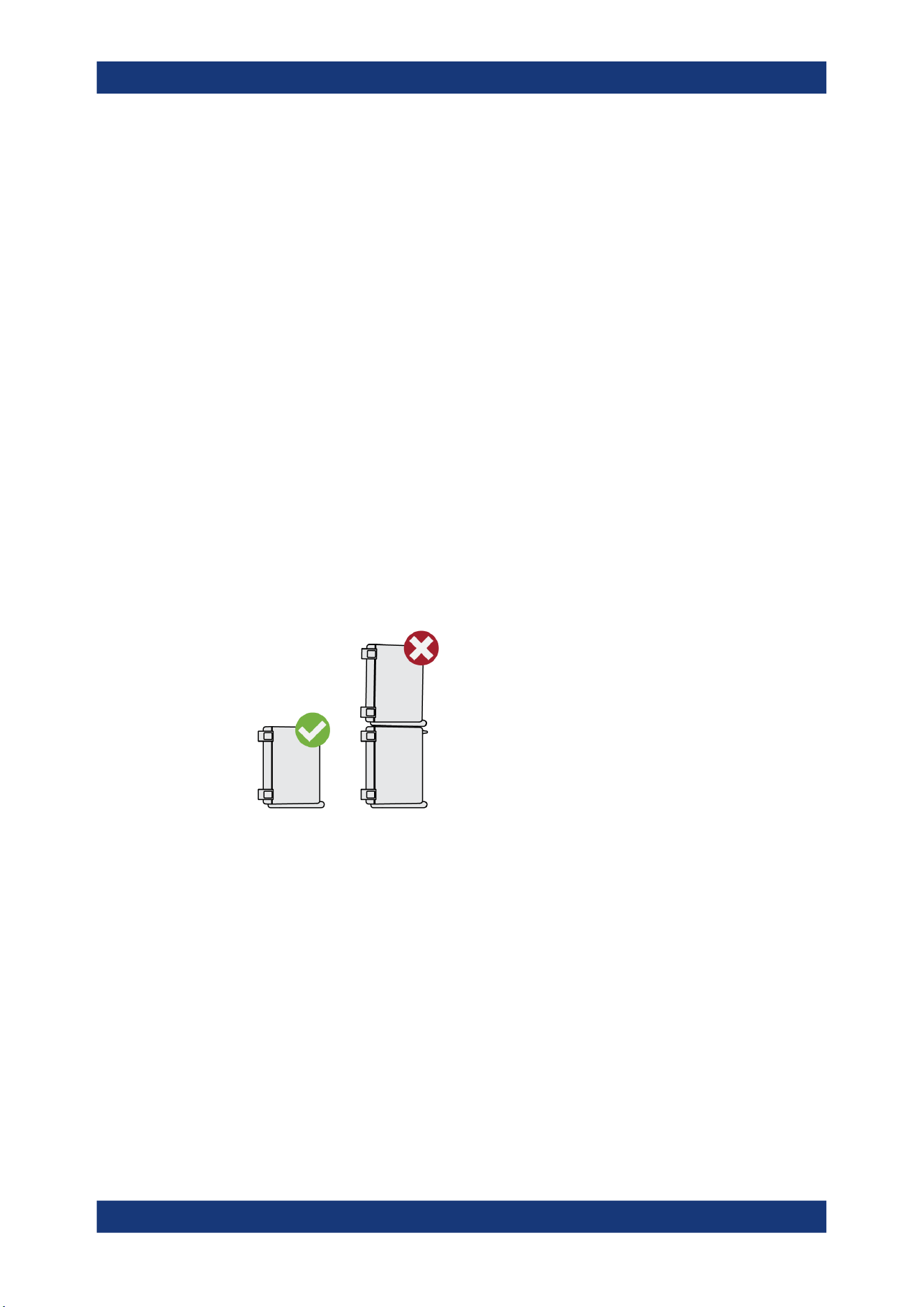
To place the product on a bench top
1. Place the product on a stable, flat and level surface.
2.
CAUTION! The top surface of the product is too small for stacking. If you stack
another product on top of the product, the stack can fall over and cause injury.
If you want to save space, mount several products in a rack.
3.
CAUTION! Foldable feet can collapse. For safety information, see "Setting up the
product" on page 16.
Always fold the feet completely in or out. With folded-out feet, do not place any-
thing on top or underneath.
4.
NOTICE! Overheating can damage the product.
Prevent overheating as follows:
● Keep a minimum distance of 10 cm between the fan openings of the product
and any object in the vicinity to provide sufficient airflow and ventilation.
● Do not place the product next to heat-generating equipment such as radiators
or other products.
Preparing for use

Getting Started
R&S
®
MXO 5 Series
26User Manual 1802.3369.02 ─ 02
3.1.4.2 Mounting the product on a monitor arm
You can mount the oscilloscope to a monitor arm with VESA mount.
1.
NOTICE! Only use a VESA mount compatible to FDMI MIS-D, up to 14kg with
M4x10 screws and standard 100 mm × 100 mm pattern.
Order the VESA adapter R&S MXO5-Z7. For the order number, see data sheet.
2. Mount the adapter to the rear panel of the oscilloscope. Follow the assembly
instructions provided with the adapter.
3. Mount the VESA mount of the monitor arm to the VESA adapter.
3.1.4.3 Mounting the product in a rack
The instrument can be installed in a rack using a rack adapter kit. The order number is
given in the data sheet. The installation instructions are part of the adapter kit.
To prepare the rack
1. Observe the requirements and instructions in "Setting up the product" on page 16.
2.
NOTICE! Insufficient airflow can cause overheating and damage the product.
Design and implement an efficient ventilation concept for the rack.
To mount the oscilloscope in a rack
1. Use an adapter kit to prepare the product for rack mounting.
a) Order the rack adapter kit designed for the R&S MXO 5 series oscilloscope.
For the order number, see data sheet.
b) Mount the adapter kit. Follow the assembly instructions provided with the
adapter kit.
2. Lift the product to shelf height. If the rack is high, use a safe climbing aid when
placing on upper shelves.
3. Grip the product by the handles. Slide the product onto the shelf until the rack
brackets fit closely to the rack.
4. Tighten all screws at the rack brackets with a tightening torque of 1.2 Nm to secure
the product at the rack.
To unmount the product from a rack
1. Loosen the screws at the rack brackets.
2. Remove the product from the rack.
3. If placing the product on a bench top again, unmount the adapter kit from the prod-
uct. Follow the instructions provided with the adapter kit.
Preparing for use

Getting Started
R&S
®
MXO 5 Series
27User Manual 1802.3369.02 ─ 02
3.1.5 Considerations for test setup
Observe safety instructions, see "Performing measurements" on page 17.
Cable selection and electromagnetic interference (EMI)
Electromagnetic interference (EMI) can affect the measurement results.
To suppress electromagnetic radiation during operation:
●
Use high-quality shielded cables, for example, double-shielded RF and LAN
cables.
●
Always terminate open cable ends.
●
Ensure that connected external devices comply with EMC regulations.
Measuring accessories
Use only probes and measuring accessories that comply with IEC 61010-031.
Signal input and output levels
Information on signal levels is provided in the data sheet. Keep the signal levels within
the specified ranges to avoid damage to the product and connected devices.
During operation, if the firmware observes a serious unexpected disturbance (e.g. due
to ESD), it resets some hardware components and initiates a new alignment to ensure
proper instrument functioning. Then it restores the user settings to the state before the
disturbance.
3.1.6 Connecting to power
For safety information, see "Connecting to power and grounding" on page 17.
The R&S MXO 5 can be used with different AC power voltages and adapts itself auto-
matically to it.
The nominal ranges are indicated on a label near the power connector on the instru-
ment and in the data sheet.
1. Plug the AC power cable into the AC power connector on the rear panel of the
product. Only use the AC power cable that is delivered with the product.
2. Plug the AC power cable into a power outlet with ground contact.
The required ratings are listed next to the AC power connector and in the data
sheet.
If the voltage dips at the AC power connector (according to EN 61326-2-1 6.4.101), a
restart of the R&S MXO 5 can happen. All instrument settings are restored after the
restart.
Preparing for use

Getting Started
R&S
®
MXO 5 Series
28User Manual 1802.3369.02 ─ 02
3.1.7 Connecting to LAN
For remote operation of the instrument using a computer, you need a local area net-
work (LAN) connection.
Network environment
Before connecting the product to a LAN, consider the following:
●
Install the latest firmware to reduce security risks.
●
For internet or remote access, use secured connections if applicable.
●
Ensure that the network settings comply with the security policies of your company.
Contact your local system administrator or IT department before connecting your
product to your company LAN.
●
When connected to the LAN, the product may potentially be accessed from the
internet, which may be a security risk. For example, attackers might misuse or
damage the product.
To connect a LAN cable
► Connect an RJ-45 cable to the LAN connector on the rear panel, and to the LAN.
For supported LAN interfaces, refer to the data sheet.
By default, the R&S MXO 5 is configured to use DHCP. Configuration of a static IP
address is not required.
3.1.8 Connecting external devices
3.1.8.1 Connecting USB devices
You can use USB connectors on the front panel and on the side or rear panel to con-
nect various devices:
●
Connect a keyboard and a mouse for operation and data entry, alternatively or in
addition to the touchscreen functionality.
●
Connect USB flash drives to save screenshots, and to transfer files to and from the
instrument without a network connection.
► Connect the USB device to any of the USB connectors.
You can connect or disconnect USB devices during operation of the instrument.
3.1.8.2 Connecting external monitors
Using the HDMI or DisplayPort connector on the side panel, you can connect one
external monitor or projector to the oscilloscope. The display connectors are not plug &
play, the monitor is recognized by the instrument during the boot process.
Preparing for use

Getting Started
R&S
®
MXO 5 Series
29User Manual 1802.3369.02 ─ 02
1.
NOTICE! Missing ground contact can damage the oscilloscope.
Ensure that the monitor and the oscilloscope are connected to a ground contact.
See also: Chapter 3.1.6, "Connecting to power", on page 27.
2.
NOTICE! Use only standard-compliant monitor cables.
Connect the monitor or projector to a monitor connector on the rear panel.
3. Switch on the oscilloscope. See also "To switch on the product" on page 29.
The oscilloscope recognizes the external monitor. During the running session, you
can disconnect the monitor and connect it again.
If the monitor provides touch functionality, an additional connection can be required,
e.g. a USB connection. Refer to the documentation of your monitor.
The oscilloscope outputs a Full HD image with 1920x1080 pixel. The instrument's dis-
play is duplicated. If the screen resolution of the monitor is set higher than the instru-
ment's resolution, the application window uses a 1920x1080 area of the monitor dis-
play. For full screen display, adjust the monitor's screen resolution.
3.1.9 Switching on or off
The instrument is switched on or off with the power switch and the [Power] key. The
[Power] key is located in the bottom left corner of the front panel. The power switch is
located at the rear panel of the instrument.
Table 3-1: Overview of power states
Status LED Power switch
Off
(unlighted)
[0] (off)
Standby
yellow
[I] (on)
Ready
green
[I] (on)
To switch on the product
The product is off but connected to power.
1. Set the switch on the power supply to position [I].
The power key on the front panel lights up.
2. Press the [Power] key on the front panel.
The instrument performs a system check, boots the operating system, and then
starts the R&S MXO 5 firmware.
The [Power] key turns green and the illuminated keys on the front panel light up. If
the previous session was terminated regularly, the oscilloscope uses the last set-
tings.
Before you start measurements, be sure to comply with the warm-up phase specified
in the data sheet.
Preparing for use

Getting Started
R&S
®
MXO 5 Series
30User Manual 1802.3369.02 ─ 02
To shut down the product
The product is in the ready state.
► Press the [Power] key.
All current settings are saved, and the software shuts down. The [Power] key turns
yellow. The standby power supplies only the power switch circuits.
The
"Power" icon in the "Menu" shuts down only the firmware application. To shut
down the instrument completely, use the [Power] key.
Remote command for firmware shutdown: SYSTem:EXIT on page 442.
To disconnect from power
The product is in the standby state.
1.
NOTICE! Risk of data loss. If you disconnect the product from power when it is in
the ready state, you can lose settings and data. Shut it down first.
Set the switch on the power supply to position [0].
The LED of the [Power] key is switched off.
2. Disconnect the product from the power source.
3.2 Instrument tour
This section describes the front, rear and side view of the instrument including all func-
tion keys and connectors.
3.2.1 Front view
This section provides an overview of the R&S MXO 5 front panel.
Instrument tour
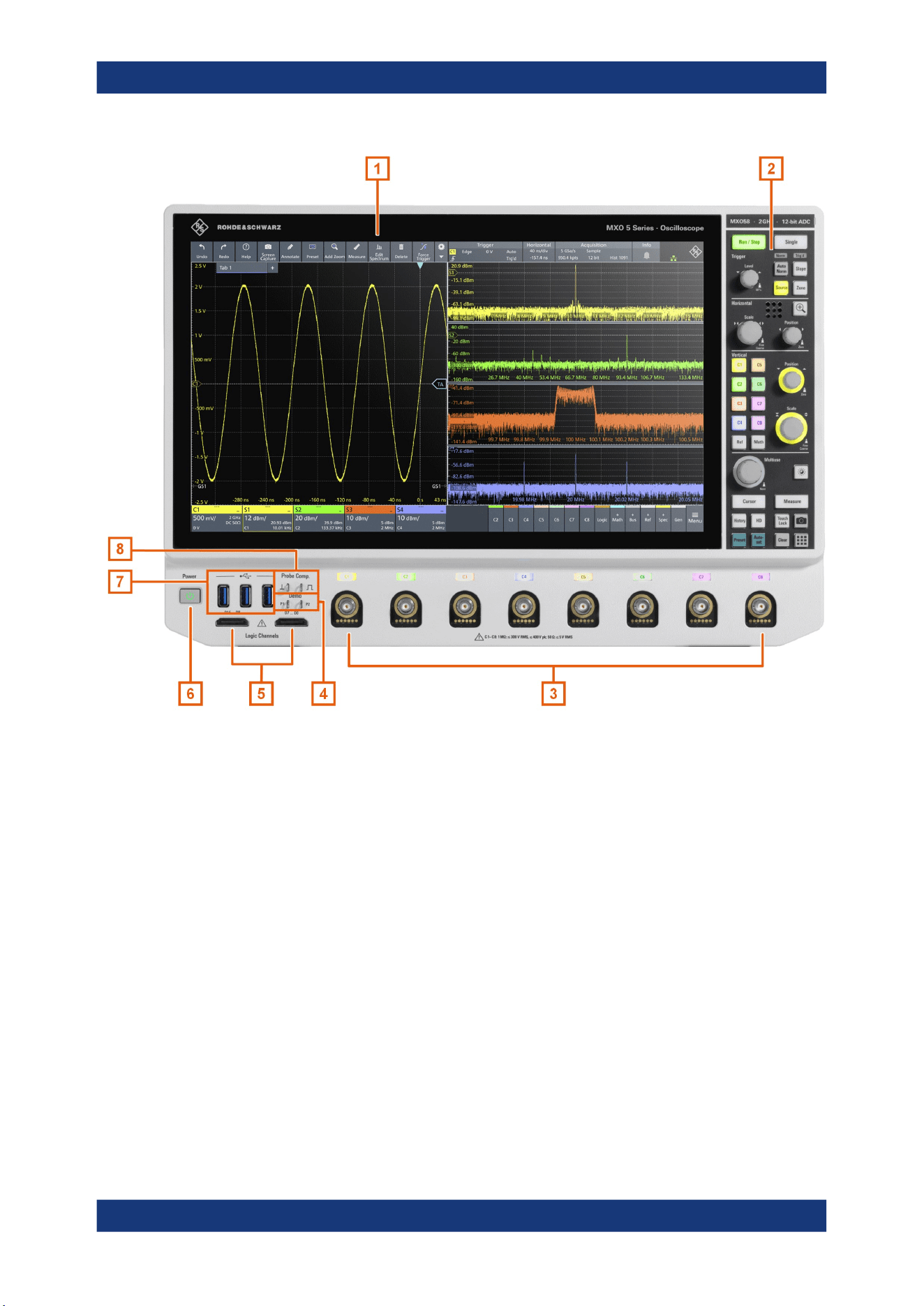
Getting Started
R&S
®
MXO 5 Series
31User Manual 1802.3369.02 ─ 02
Figure 3-1: Front view of R&S
MXO
558, with 8 input channels
1 = Display
2 = Keys and controls
3 = Analog input channels
4 = Connectors for demo signal output
5 = Connectors for logic probe (R&S MXO5-B1 Mixed Signal Option)
6 = [Power] key
7 = USB connectors
8 = Connectors for probe compensation
Analog channel inputs
The R&S MXO 5 has 4 or 8 channel inputs to connect the input signals, depending on
the model.
You can connect probes with Rohde & Schwarz probe interface or BNC connectors.
The input impedance is selectable, the values are 50 Ω and 1 MΩ.
The maximum input voltage on channel inputs is:
●
400 V (V
p
) and 300 V (RMS) at 1 MΩ input impedance
●
30 V (V
p
) and 5 V (RMS) at 50 Ω input impedance
Instrument tour

Getting Started
R&S
®
MXO 5 Series
32User Manual 1802.3369.02 ─ 02
Demo
The pins are intended for demonstration purposes.
Logic Channels
Two connectors for logical probes with 8 digital channels each (D0 to D7 and D8 to
D15). Using logic channels requires the Mixed Signal Option R&S MXO5-B1.
The maximum input voltage is 40 V (Vp) at 100 kΩ input impedance. The maximum
input frequency for a signal with the minimum input voltage swing and medium hystere-
sis of 800 mV (Vpp) is 400 MHz.
USB
Three USB 3.1 gen1 interfaces of type A. They are used to connect a mouse or key-
board, a USB flash drive for storing and reloading instrument settings and measure-
ment data, and to update the firmware.
Probe Comp.
Probe compensation terminal to adjust passive probes to the input channel.
Square wave signal for probe compensation.
Ground connector for probes.
3.2.2 Side view
On the side of the instrument, you can find the computer connectors and the ground
connector for probes.
Instrument tour
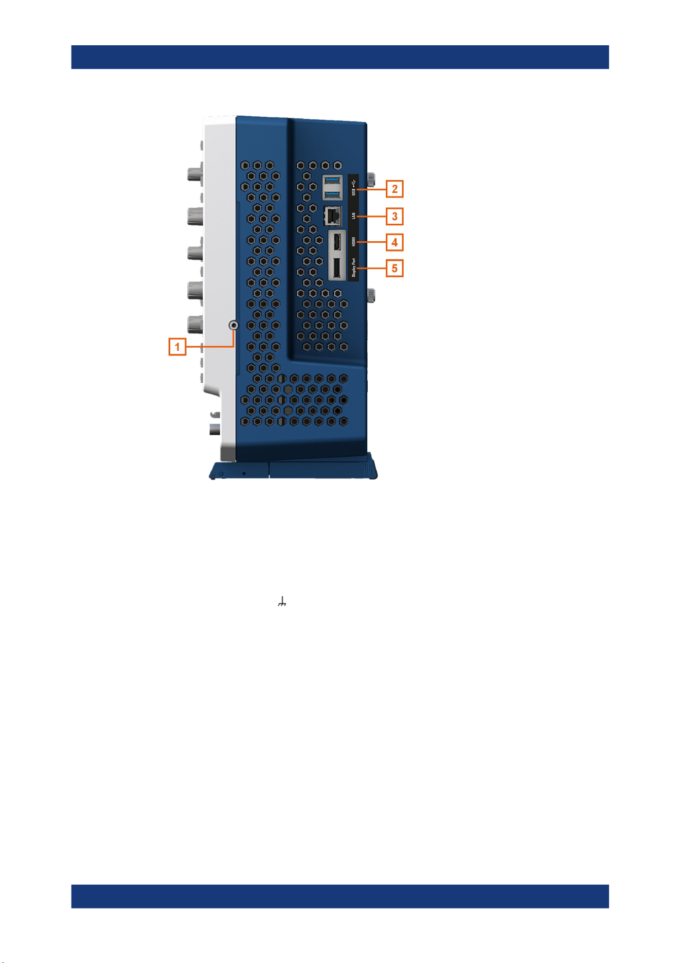
Getting Started
R&S
®
MXO 5 Series
33User Manual 1802.3369.02 ─ 02
Figure 3-2: Side view of R&S
MXO
5
1 = Grounding terminal
2 = USB connector
3 = LAN connector
4 = HDMI display output
5 = DisplayPort connector
Grounding terminal
4 mm banana jack to connect ground of DUT and test fixtures, and wrist strap.
USB
Two USB 3.1 gen1 interfaces of type A.
LAN
8-pin connector RJ-45 used to connect the instrument to a Local Area Network (LAN).
It supports up to 1 Gbit/s.
HDMI
HDMI Version 2.0 connector for an external monitor or projector. The monitor shows
the complete content of the instrument's screen.
DisplayPort
DisplayPort connector for an external monitor or projector. It supports DisplayPort++
version 1.3.
Instrument tour
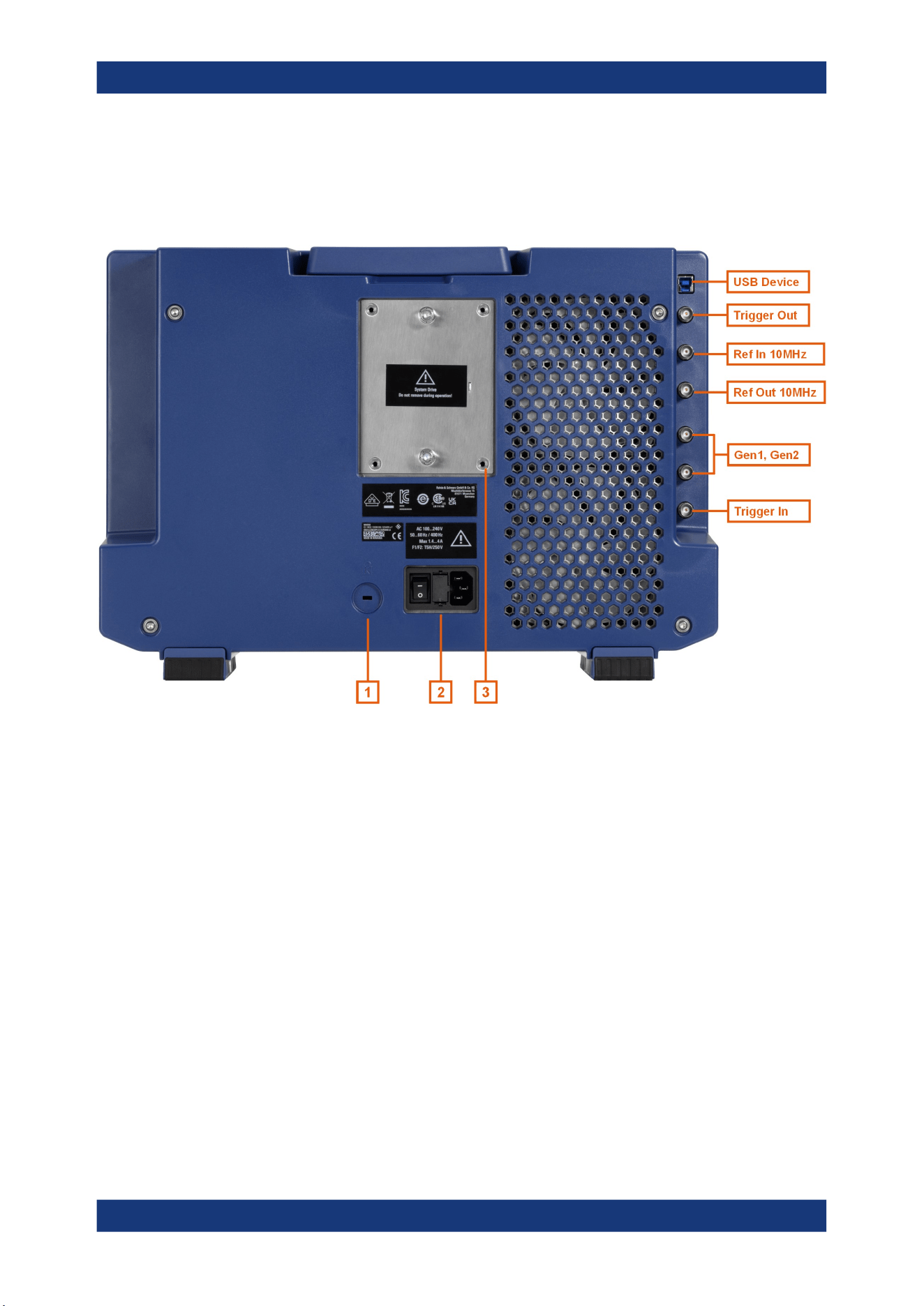
Getting Started
R&S
®
MXO 5 Series
34User Manual 1802.3369.02 ─ 02
3.2.3 Rear view
On the rear panel of the R&S MXO 5, you find more connectors and the power supply
switch.
Figure 3-3: Rear panel view of R&S
MXO
5
USB Device = USB connector, type B
Trigger Out = BNC connector for trigger out signal
Ref In 10 MHz = BNC connector for incoming reference signal
Ref Out 10 MHz = BNC connector for outgoing reference signal
Gen1, Gen2 = BNC connectors for optional function generator output (option R&S MXO5-B6)
Trigger In = BNC connector for external trigger input
1 = Kensington lock slot to secure the instrument against theft
2 = AC power supply connector and main power switch
3 = Exchangeable solid state disk (SSD, option R&S MXO5--B19)
USB Device
USB 3.1 gen1 interface of type B (device USB), to be used for remote control of the
instrument.
Trigger Out
BNC output that can function as pass/fail output or trigger output.
Ref In 10 MHz
BNC input connector for 10 MHz reference frequency signals.
Instrument tour

Getting Started
R&S
®
MXO 5 Series
35User Manual 1802.3369.02 ─ 02
Ref Out 10 MHz
BNC output for 10 MHz frequency reference. Can be switched between internal and
external reference.
See also: "Menu" > "Horizontal" > "Setup" tab > "Ref Clock"
Gen1, Gen2: Function generator
BNC output of the function generator, requires option R&S MXO5-B6.
Trigger In
The external trigger input is a BNC connector that is used to control the measurement
by an external signal. The trigger level can be set from -5 V to 5 V.
For the external trigger input, the maximum input voltage is 400 V (V
p
) and
300 V (RMS) at 1 MΩ input impedance.
Transient overvoltages on all input connectors must not exceed 400 V (V
p
).
AC power supply connector and main power switch
The instrument supports a wide range power supply. It automatically adjusts to the cor-
rect range for the applied voltage. There is no line voltage selector.
The AC main power switch disconnects the instrument from the AC power line.
When you power up the instrument, be sure to comply with the warm-up phase speci-
fied in the data sheet before you start measurements.
3.2.4 Keys and controls
For an overview of the front panel keys, see Chapter 3.2.1, "Front view", on page 30.
3.2.4.1 Power key
The [Power] key is located on the lower left corner of the front panel. It starts up and
shuts down the instrument's software.
The light of the key shows the instrument state, see Chapter 3.1.9, "Switching on or
off", on page 29.
Remote command: SYSTem:SHUTdown on page 442.
3.2.4.2 Trigger controls
The keys and knob in the Trigger functional block adjust the trigger and start or stop
acquisition.
Instrument tour
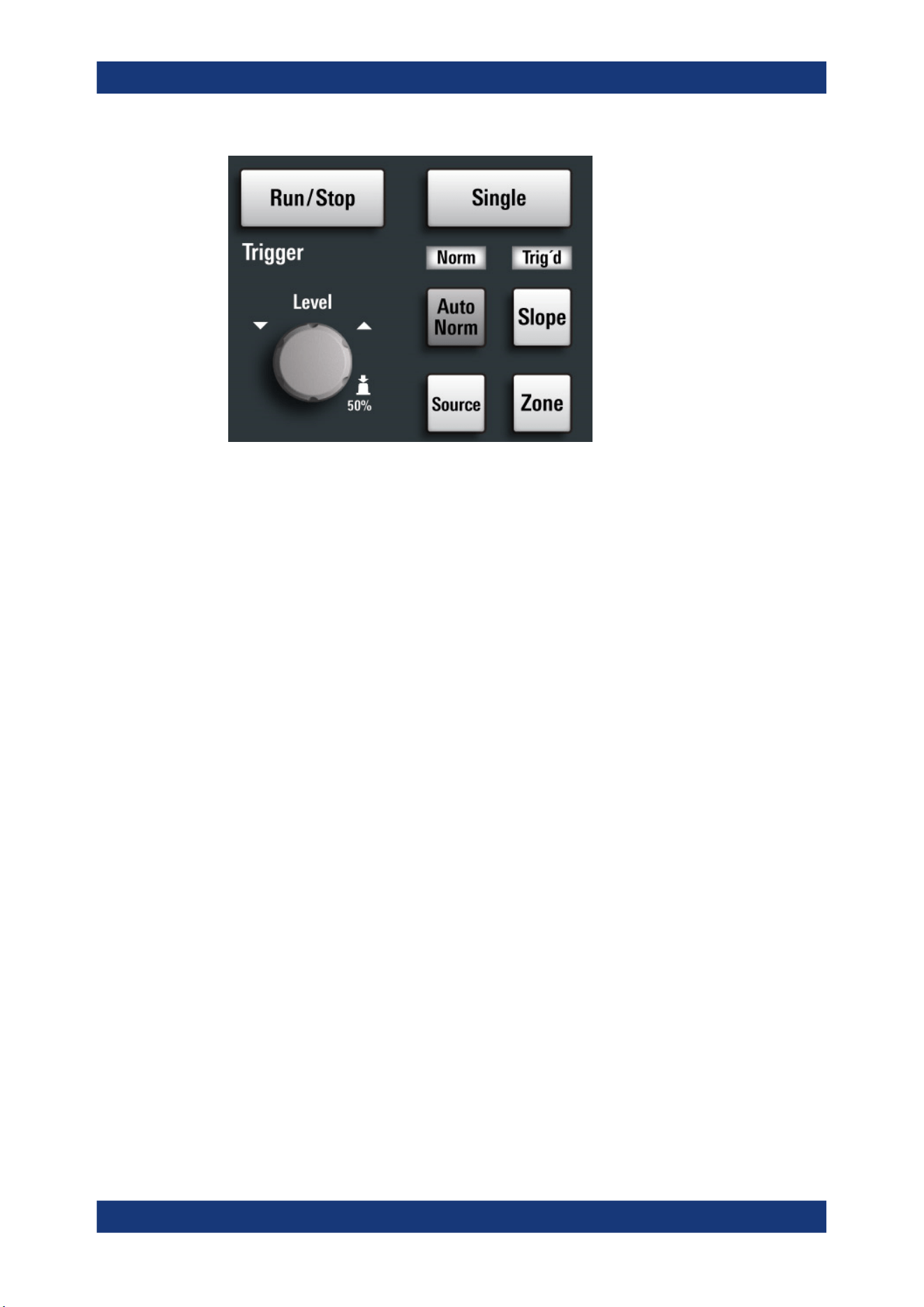
Getting Started
R&S
®
MXO 5 Series
36User Manual 1802.3369.02 ─ 02
[Run / Stop]
Starts and stops the continuous acquisition. The [Run / Stop] key lights green when the
acquisition is running. When the acquisition is stopped, the key lights red.
[Single]
Starts a defined number of acquisitions. The [Single] key lights green when the acquisi-
tion is running. When the acquisition is stopped, the key lights red.
[Auto Norm]
Toggles the trigger mode between "Auto" and "Normal". The current setting is shown
on the trigger label.
Auto
The instrument triggers repeatedly after a time interval if the trigger
conditions are not fulfilled. If a real trigger occurs, it takes prece-
dence. The time interval depends on the time base.
Norm
The instrument acquires a waveform only if a trigger occurs. The
"Norm" LED lights up in green.
[Source]
Toggles the trigger source between the channels: C1...C8. The key lights up in the
color of the selected channel.
[Slope]
Toggles the trigger slope or trigger polarity, dependent on the trigger type. The current
setting is shown on the trigger label.
[Zone]
Opens a dialog to configure the zone trigger. A zone trigger combines the trigger condi-
tion with the intersection or non-intersection of one or more zones or masks.
Instrument tour
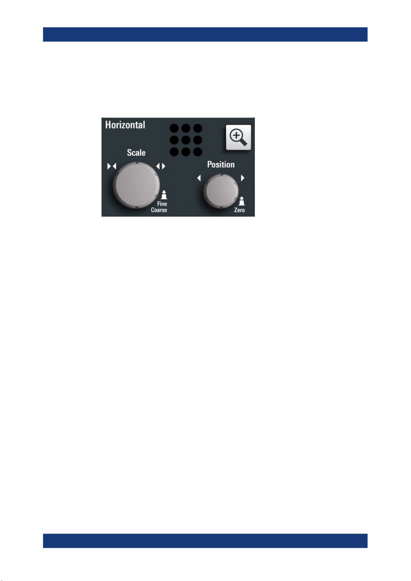
Getting Started
R&S
®
MXO 5 Series
37User Manual 1802.3369.02 ─ 02
3.2.4.3 Horizontal controls
The rotary knobs in the Horizontal functional block adjust the horizontal parameters.
These settings are effective for all channel waveforms. In addition, a [Zoom] key is
available.
[Position]
The rotary knob changes the horizontal position of the waveforms. Turn clockwise to
move the waveforms to the right. To set the value to zero, press the knob. The current
value is shown in the "Horizontal" label above the diagram.
The horizontal position defines the zero point of the diagram. It is the time distance to
the reference point, which marks the rescaling center of the time scale.
[Scale]
The rotary knob adjusts the time scale for all signals. The time scale is also known as
timebase.
Turn clockwise to stretch the waveforms. Doing so, the scale value time/div decreases.
Press the knob to toggle between coarse and fine scale adjustment.
[Zoom]
Activates a zoom and supports the zoom setup.
If no zoom is on, the first press opens a zoom diagram for the active diagram. If at
least one zoom is shown, the keypress opens the "Zoom" dialog. If only one zoom is
defined, the next press closes the dialog and removes the zoom. If several zooms are
defined and the dialog is open, the key toggles the zooms.
3.2.4.4 Vertical controls
The keys and knobs in the Vertical functional block select a signal and adjust the verti-
cal scale and position of the selected signal.
Instrument tour
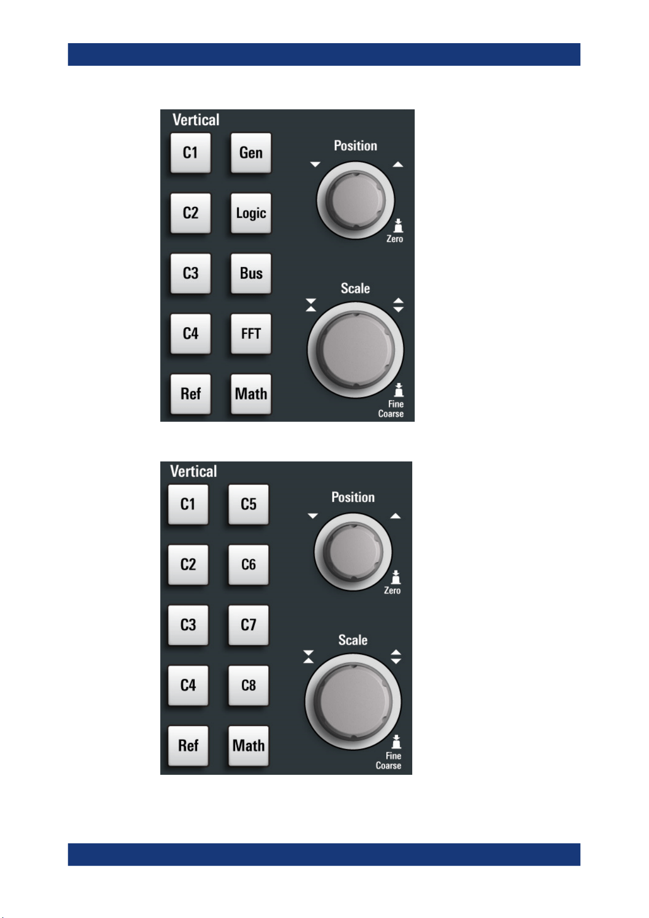
Getting Started
R&S
®
MXO 5 Series
38User Manual 1802.3369.02 ─ 02
Figure 3-4: Vertical controls of R&S
MXO
5 with 4 input channels
Figure 3-5: Vertical controls of R&S
MXO
5 with 8 input channels
Instrument tour

Getting Started
R&S
®
MXO 5 Series
39User Manual 1802.3369.02 ─ 02
[Position]
The vertical [Position] knob changes the vertical offset or the position of the selected
waveform. The horizontal axis and the selected waveform are moved vertically. You
can select whether the knob changes the offset or the position in the "Menu" > "Set-
tings" > "Frontpanel" > "Knobs" dialog.
●
Position indicates the vertical location in divisions.
●
Offset moves the vertical center of the selected channel to the offset value.
If the selected waveform is a math or reference waveform, serial bus, or logic channel,
the knob changes its vertical position.
The knob lights up in the color of the selected waveform. Turn clockwise to move up
the waveform. To set the value to zero, press the knob.
The current offset value is shown in the channel icon.
Remote command:
CHANnel<ch>:POSition on page 466
CHANnel<ch>:OFFSet on page 465
[Scale]
Sets the vertical scale, which defines the displayed amplitude of the selected wave-
form.
The [Scale] knob lights up in the color of the selected waveform.
Turn the knob clockwise to stretch the waveform. Doing so, the scale value V/div
decreases. Press the knob to toggle between fine and coarse adjustment. For analog
waveforms, the scale value is shown in the signal icon.
To get the maximum resolution of the waveform amplitude, make sure that the wave-
forms cover most of the diagram's height.
Remote command:
CHANnel<ch>:SCALe on page 465
CALCulate:MATH<m>:VERTical:SCALe[:VALue] on page 528
REFCurve<rc>:SCALe on page 537
[Gen]
Available only for R&S MXO 5 with 4 input channels.
Opens the "Waveform Generator" dialog, if option R&S MXO5-B6 is installed.
The waveform generator can generate various function and arbitrary waveforms,
sweeps, and parallel patterns. For detailed specifications, refer to the data sheet.
[Logic]
Available only for R&S MXO 5 with 4 input channels.
Opens the "Logic" dialog to configure and enable the logic buses L1 to L4. A logic bus
(or parallel bus) has up to 16 logic (digital) channels. If logic buses are active, pressing
the key toggles these buses.
The key lights up if at least one logic bus is enabled.
[Bus]
Available only for R&S MXO 5 with 4 input channels.
Instrument tour
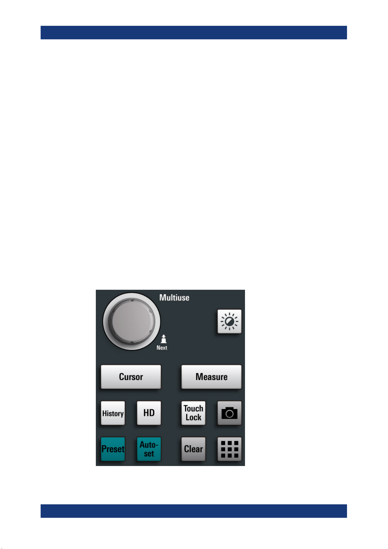
Getting Started
R&S
®
MXO 5 Series
40User Manual 1802.3369.02 ─ 02
Opens and closes the "Protocol" tab in the "Apps" dialog, where you can select the
required serial protocol and proceed to the protocol setup. The key lights up if the
decoding of a serial bus is active.
[FFT]
Available only for R&S MXO 5 with 4 input channels.
Opens and closes the "Spectrum" dialog. The key lights up if a spectrum is active.
[Ref]
Opens the "Reference" dialog box, where you can configure and display reference
waveforms. Press the key repeatedly to switch the reference waveform.
If a reference waveform is selected, the vertical rotary knobs are illuminated in white or
light gray (default colors), depending on the selected waveform.
[Math]
Opens the "Math" dialog, where you can configure the calculation of mathematical
waveforms using various mathematic operations on other waveforms. Press the key
repeatedly to toggle the selected math waveform. If no math waveform is active, the
key closes the dialog.
If a math waveform is selected, the vertical rotary knobs are illuminated in blue (default
color).
3.2.4.5 Analysis keys
The controls in the bottom functional block have various functions.
Instrument tour

Getting Started
R&S
®
MXO 5 Series
41User Manual 1802.3369.02 ─ 02
[Multiuse]
The multiuse knob changes the element that is in focus. It lights up when a function is
active on the knob.
[Intensity]
Adjusts the intensity of the waveforms on the screen.
[Cursor]
Starts a cursor measurement: sets vertical and horizontal cursors in the active dia-
gram, and displays results of the cursor measurement. If cursors are already set, the
keypress opens the "Cursor" dialog, where you can adjust the settings. The next key-
press closes the dialog.
Cursors are markers which are placed at points of interest on a waveform. The instru-
ment measures the cursor positions and delta values between parallel cursors.
[Measure]
Opens the "Measurement" dialog, where you can set up various measurements.
[History]
Activates the history and opens the history player. The next keypress closes the player.
The history shows stored acquisitions that were acquired before the current one. The
key is illuminated as long as the history is active.
[HD]
Activates the high definition mode and opens the "HD Mode" dialog box.
If the dialog is open, pressing the key closes the dialog. If the dialog is closed, the key
disables the high definition mode. The key is illuminated as long as the HD mode is
active.
[Touch Lock]
Locks the touchscreen to prevent unintended use. When the touchscreen is off, the
key is illuminated. Press again to unlock the touchscreen.
Camera
Saves a screenshot of the waveform display.
[Preset]
Resets the instrument to a predefined state and starts the continuous acquisition. All
measurements, mask tests, zoom, and most individual settings are deleted, and all
channels except for channel 1 are disabled. You can define preset configurations and
save them to a file. The [Preset] key can be configured to set either factory defaults or
a user-defined preset configuration.
[Autoset]
The instrument analyzes the enabled channel signals, and adjusts appropriate horizon-
tal, vertical, and trigger settings to display stable waveforms.
Instrument tour

Getting Started
R&S
®
MXO 5 Series
42User Manual 1802.3369.02 ─ 02
In particular, the horizontal scale is set to a common value for all active channels,
record length and sample rate are set to automatic detection. Vertical scale and offset
are set for each channel individually. Probe settings, channel coupling and impedance
remain unchanged. The trigger source is set to the signal with the lowest frequency,
and the trigger type to positive edge. The trigger level is adjusted, and the trigger posi-
tion is set to the reference point. Measurements, math and spectrum waveforms are
kept. Undo and redo of an autoset is possible.
[Clear]
Deletes all measurement results including long-term measurement and statistics, all
waveforms, and the history.
Apps
Opens the "Apps" dialog, where you can start an application, serial protocol or another
analysis function.
3.2.5 Checking the functionality
To check if the instrument works correctly, you can use the probe compensation signal
and check the displayed signal.
1. Perform a self-alignment of the instrument:
a) Warm up the instrument. The minimum warm-up time is indicated in the data
sheet.
b) Remove all probes from the input connectors.
c) Open the "Menu", and select "Settings" > "Maintenance" > "Alignment".
d) Tap "Start Alignment". Wait until the alignment has finished successfully.
2.
Connect the probe's ground connector to the ground pin
, and the tip to the
square wave pin .
3. Press the [Preset] key.
4. Connect the probe to the input connector [C1].
The instrument recognizes the probe, and a signal is displayed in the diagram.
5. Tap the signal icon of C1 to open the vertical settings.
6. In the "Vertical" > "Setup" dialog, adjust the following:
● "Vertical scale" = 600 mV/div
● "Offset" = 900 mV
Instrument tour
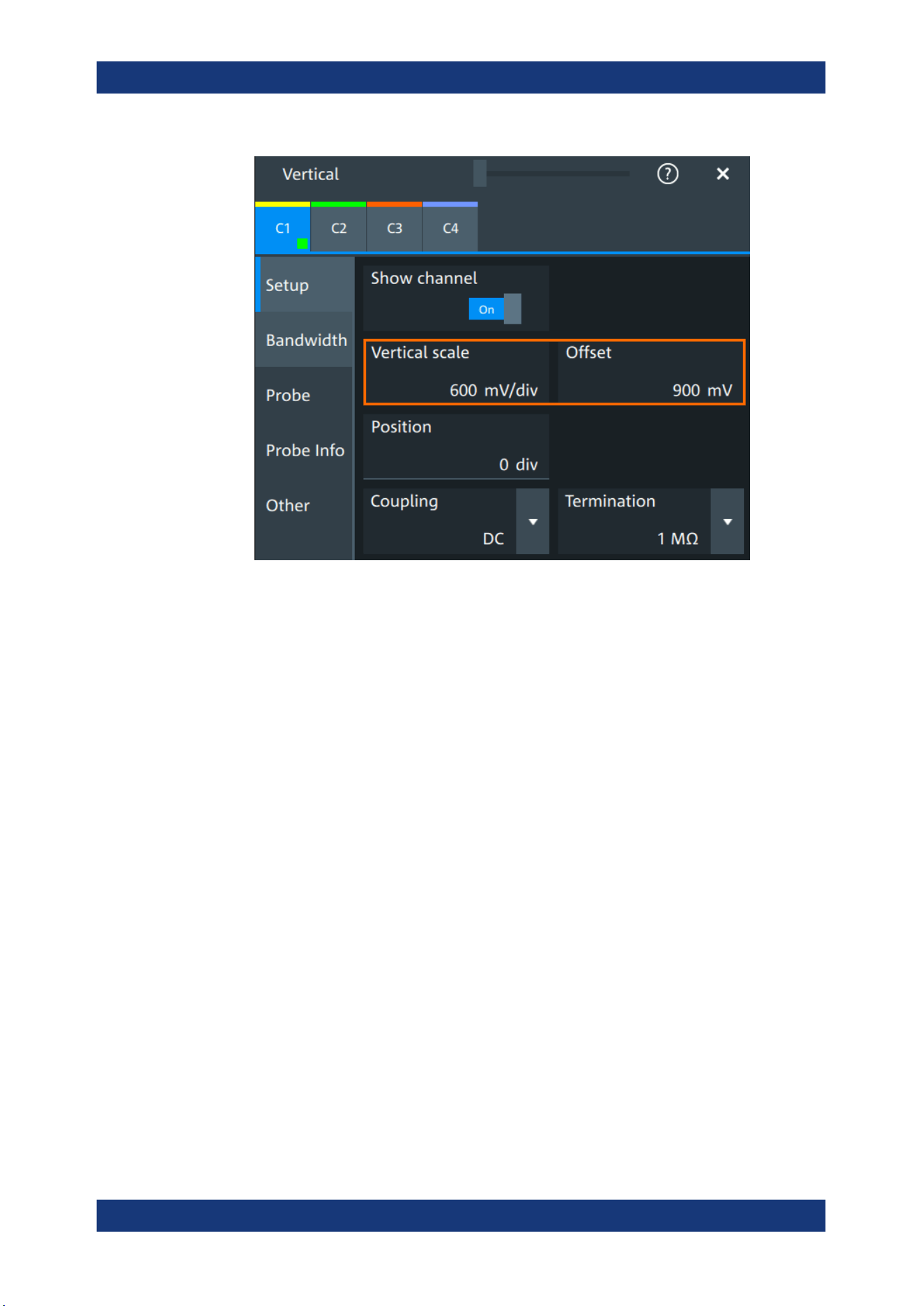
Getting Started
R&S
®
MXO 5 Series
43User Manual 1802.3369.02 ─ 02
7. Turn the horizontal [Scale] knob to set the horizontal scale to 1 ms/div.
8. Press the [Source] key to set the trigger source to C1. The color of the key indi-
cates the selected channel.
9. Turn the [Level] knob to set the trigger level to 300 mV.
10. Check the rectangle signal on the screen. The displayed signal should have an
amplitude of about 3.3 V, which covers 5.5 divisions.
Instrument tour
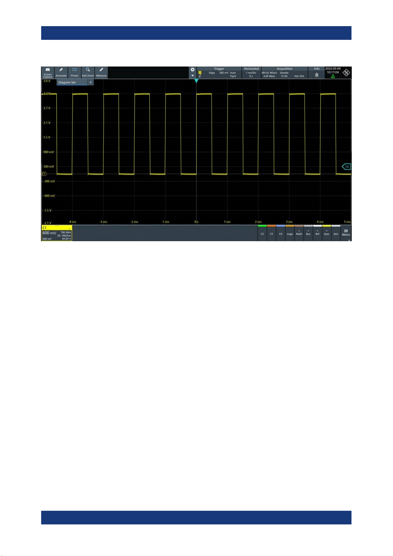
Getting Started
R&S
®
MXO 5 Series
44User Manual 1802.3369.02 ─ 02
11. Repeat steps 4 to 10 for all other channels. Make sure to adjust the vertical set-
tings for the connected channel, and also to set the trigger source to the connected
channel.
Instrument tour

Operating the instrument
R&S
®
MXO 5 Series
45User Manual 1802.3369.02 ─ 02
4 Operating the instrument
There are three ways to operate the R&S MXO 5.
Manual operation
Use the touchscreen, keys and rotary knobs, or an optional mouse and/or keyboard.
The principles of manual operation are explained in this section.
Remote control
Create programs to automatize repeating settings, tests, and measurements. The
instrument is connected to a computer that runs the program.
This way of operation is described in: Chapter 17, "Remote control commands",
on page 428.
Remote operation
For remote monitoring and operation of the instrument, a VNC server is installed on the
R&S MXO 5. You need a LAN connection to the computer, and a VNC client or web
browser to connect to the instrument.
For details, refer to Chapter 16, "Network operation and remote control", on page 407.
4.1 Means of manual interaction
The R&S MXO 5 provides the following means of manual interaction, which you can
use alternatively or complementary:
●
Touchscreen:
Using the touchscreen allows for direct interaction with the instrument. Use your
finger to place waveforms on the screen, mark areas for zoom, set parameters in
dialogs, enter data, and much more. The control elements and actions on the
screen are based on common concepts, and you easily become familiar with the
user interface.
Tapping the screen works like clicking mouse buttons:
– Tap = click: Selects a waveform or parameter, or provokes an action.
– Double-tap = double-click: Has the same effect as touch and hold, it opens the
on-screen keyboard or keypad, or a specific editor if available.
●
Function keys and rotary knobs:
The front panel provides frequently used functions and controls to operate the
instrument. Use knobs to set levels and scales, and keys to initiate actions and to
open dialogs.
●
Optional mouse and/or keyboard
These devices work in the normal manner.
Means of manual interaction
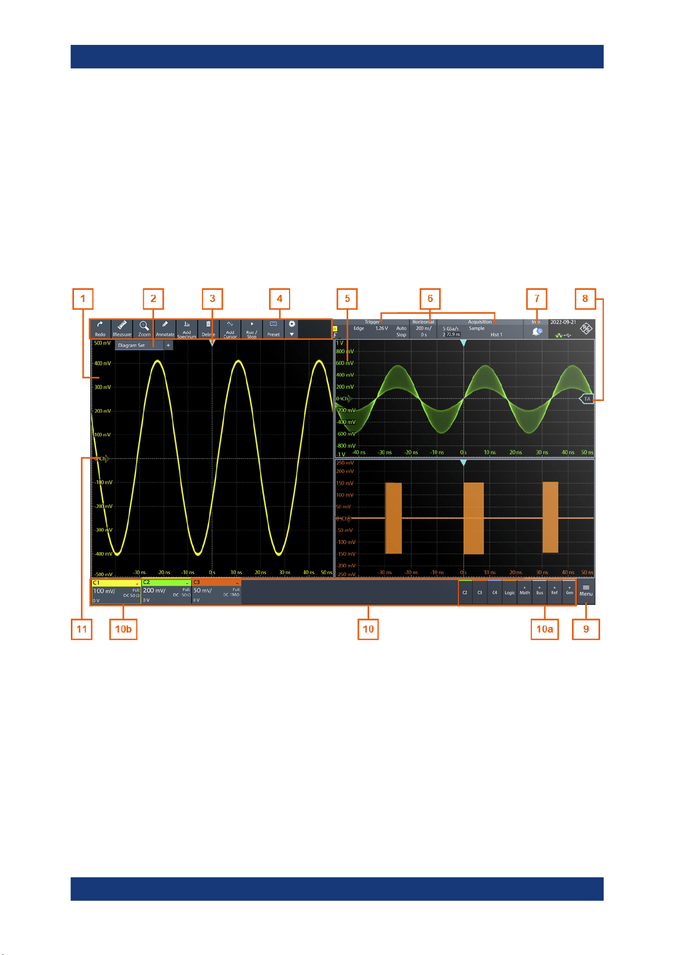
Operating the instrument
R&S
®
MXO 5 Series
46User Manual 1802.3369.02 ─ 02
4.2 Touchscreen display
4.2.1 Information on the display
The GUI of the instrument shows the waveforms and measurement results, and also
information and everything that you need to control the instrument. All waveform-rela-
ted GUI elements are shown in Figure 4-1. An overview of control elements - like dia-
log box, toolbar - is given in Chapter 4.2.2, "Control elements on the GUI",
on page 49.
Figure 4-1: Information in the graphical user interface
1 = Diagram
2 = Layout
3 = Trigger position
4 = Toolbar
5 = Grid
6 = Trigger, horizontal and acquisition label
7 = Info
8 = Trigger level
9 = Menu
10 = Signal bar with signal activators (10a), and active waveforms (10b)
11 = Channel markers indicate the ground levels
Touchscreen display
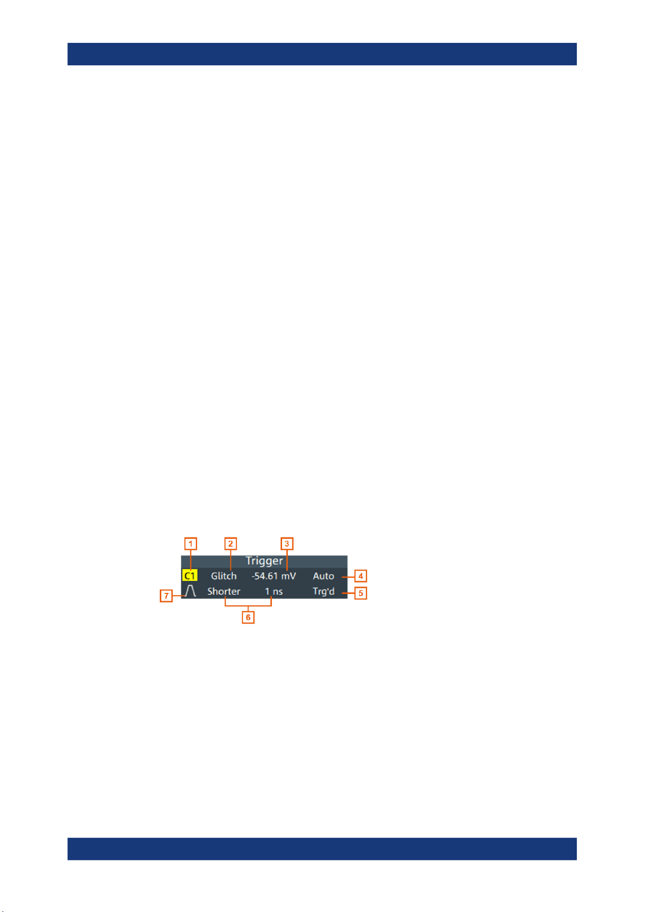
Operating the instrument
R&S
®
MXO 5 Series
47User Manual 1802.3369.02 ─ 02
Diagram
A diagram shows one or more waveforms: analog and digital channels, reference and
math waveforms, track, and serial buses. Zoom details, spectrum and other special
waveforms are shown in separate diagrams. One diagram can hold up to 16 analog
waveforms, i.e. analog channels, reference and math waveforms, and tracks.
To arrange the diagrams on the screen, the Rohde & Schwarz SmartGrid function
helps you to find the target place simply and quickly. For details, see Chapter 4.5,
"Rohde & Schwarz SmartGrid", on page 54. You can also adjust the diagram size by
dragging the diagram border.
Layout
A layout shows a set of diagrams and result tables. You can configure up to four lay-
outs using the SmartGrid functionality. For details, see Chapter 4.5, "Rohde & Schwarz
SmartGrid", on page 54.
Grid
The grid shows the vertical and horizontal divisions. The division lines are labeled with
the correspondent values. The grid labels have the color of the waveform to which they
belong. If several waveforms are shown in one diagram, the grid has the color of the
selected waveform.
Trigger position and trigger level
The blue markers show the horizontal position of the trigger and the vertical trigger
level. You can touch and move the trigger markers in the diagram to set the positions.
The trigger point is the zero point of the diagram.
The trigger position can be moved outside the diagram.
Trigger
The "Trigger" label shows the main trigger settings. If you tap the label, the corre-
sponding dialog box opens.
Figure 4-2: Trigger label
1 = Trigger source
2 = Trigger type
3 = Trigger level
4 = Trigger mode
5 = Trigger state
6 = Trigger type specific settings
7 = Trigger slope
See also: Chapter 7.1.1, "Trigger information", on page 135.
Touchscreen display

Operating the instrument
R&S
®
MXO 5 Series
48User Manual 1802.3369.02 ─ 02
Horizontal
The "Horizontal" label shows the main timebase settings. If you tap the label, the corre-
sponding dialog box opens.
Figure 4-3: Horizontal label
1 = Time scale
2 = Horizontal position
Acquisition
The "Acquisition" label shows the main acquisition settings, and the progress of long
acquisitions. If you tap the label, the corresponding dialog box opens.
Figure 4-4: Acquisition label
1 = Sample rate
2 = Record length
3 = Acquisition mode
4 = Number of acquired waveforms
5 = Resolution
See also: "Progress information" on page 66.
Info
The "Info" button on the toolbar points to the status messages of the instrument. To
open the message box, tap the button. See also: Chapter 4.11, "Information and notifi-
cations", on page 65.
Signal bar
The signal bar is the control center for all waveforms. All enabled waveforms are
shown on the left side of the signal bar. On the right side of the signal bar, you see the
signal activators of inactive waveforms. Tap a signal activator to enable the waveform.
Each waveform is represented by a signal icon. If the waveform is shown in a diagram,
the signal icon displays its main vertical and probe settings. If you tap a signal icon, the
dialog with vertical settings for this waveform opens. If you tap the "Minimize" icon on
the signal icon, the waveform switches from the diagram area to the signal icon: the
icon is grayed out. See Chapter 4.4, "Working with waveforms", on page 52 for a
detailed description.
In Figure 4-1, the signal icons C1, C2 and C3 show the main settings, and the wave-
forms are displayed in diagrams.
Touchscreen display
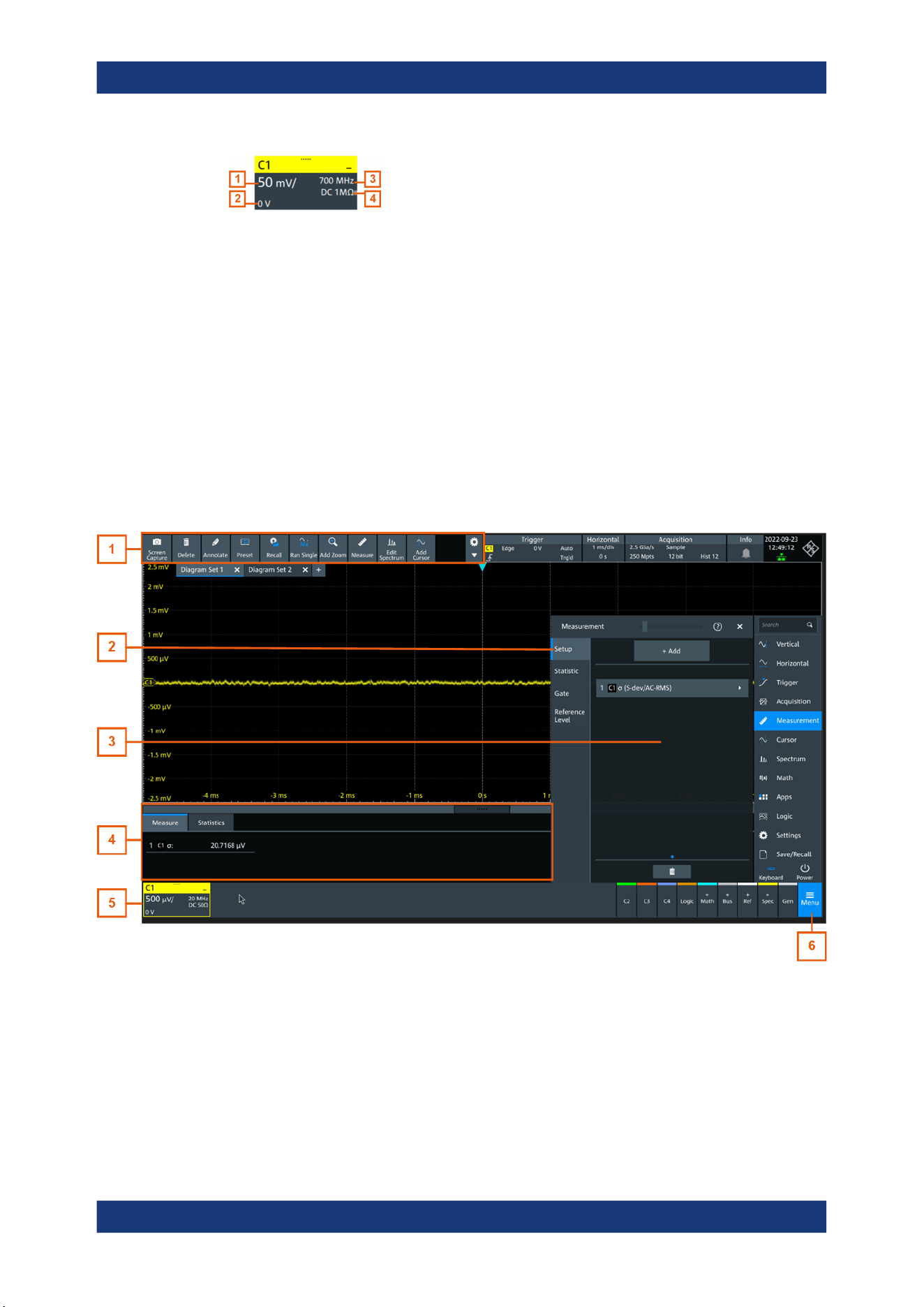
Operating the instrument
R&S
®
MXO 5 Series
49User Manual 1802.3369.02 ─ 02
Figure 4-5: Signal label
1 = Vertical scale
2 = Offset
3 = Bandwidth
4 = Coupling and termination
If many waveforms are active, then waveforms of the same type are grouped in one
signal icon. Tap the group icon to open the individual signal icons.
4.2.2 Control elements on the GUI
The GUI provides everything that you need to control the instrument, to analyze wave-
forms, and to get measurement results. Figure 4-6 shows the control elements at a
glance.
Figure 4-6: Control elements on the graphical user interface
1 = Toolbar
2 = Tab in a dialog box
3 = Dialog box
4 = Result table
5 = Signal bar
6 = Menu
Touchscreen display

Operating the instrument
R&S
®
MXO 5 Series
50User Manual 1802.3369.02 ─ 02
Toolbar (1)
The icons on the toolbar provide quick and easy access to the most important function-
ality. For a detailed description, refer to Chapter 4.6, "Toolbar", on page 56.
If you adjust the settings of an analyzing function, e.g., cursor measurement, the over-
lay menu is shown instead of the icons. The overlay menu provides the most important
settings of the current action. If you need more settings, "Setup" opens the correspond-
ing dialog box.
Dialog box (2, 3)
The tabs of the dialog boxes contain all task-oriented settings and operations, and but-
tons for calling related tabs. The usage of dialog boxes is described in Chapter 4.7,
"Using dialog boxes", on page 59.
Result table (4)
If you perform cursor or automatic measurements, the result table shows the results of
the action below the diagrams. You can move the result tables to the left or right of the
diagrams.
See also: Chapter 4.9, "Displaying results", on page 62.
Signal bar (5)
The signal bar summarizes all waveforms as described in "Signal bar" on page 48.
Menu (6)
The menu provides access to the complete functionality of the R&S MXO 5.
At the top of the menu, you can find a search box for a quick access to any parameter
you need. A list of all found results is shown on the left side of the menu. Tap the result
entry and the dialog containing this parameter opens.
Touchscreen display
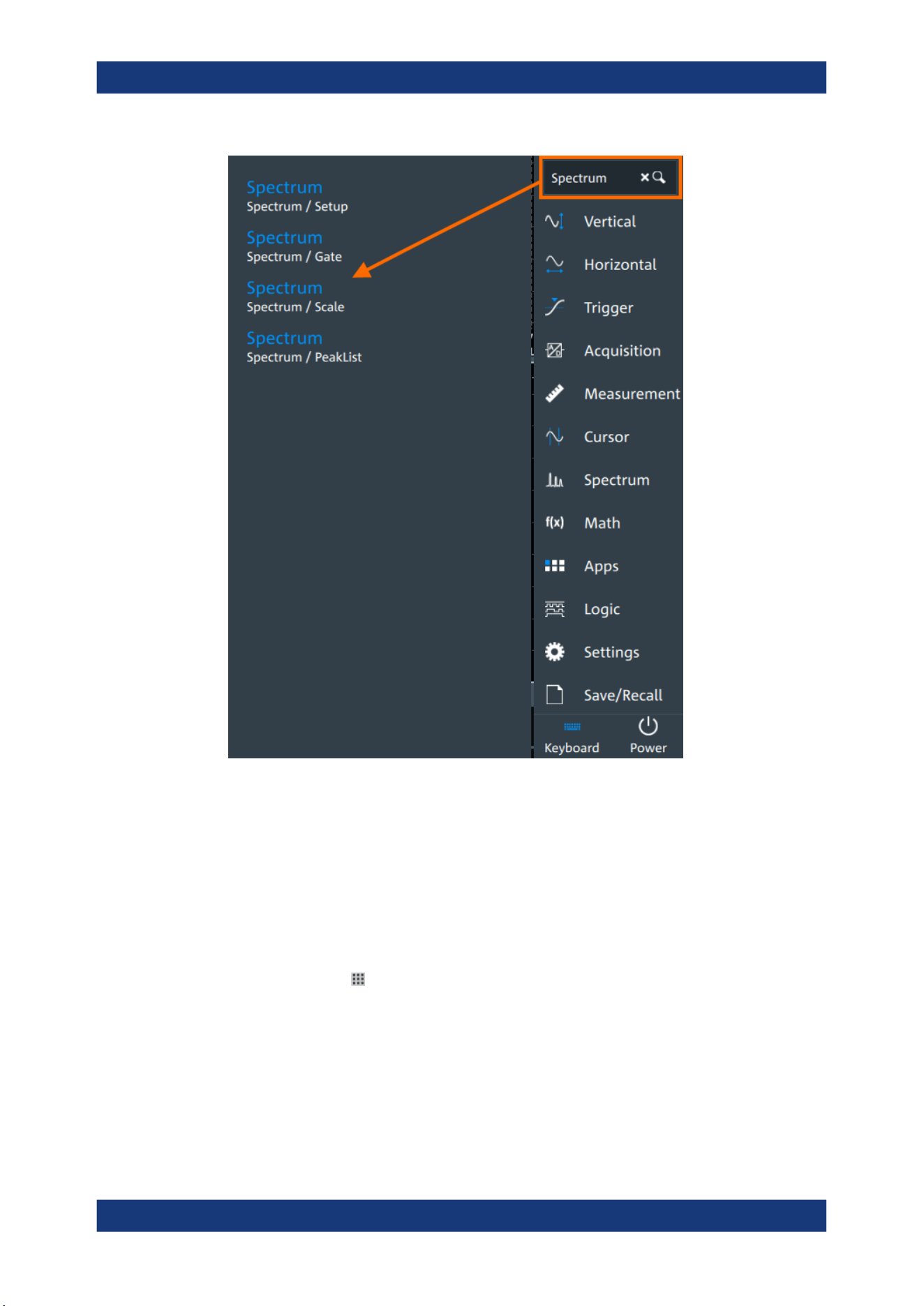
Operating the instrument
R&S
®
MXO 5 Series
51User Manual 1802.3369.02 ─ 02
4.3 Applications
The "Apps" dialog provides fast access to all available applications, for example, to
serial protocols, frequency response analysis or file browser.
► To open the "Apps" dialog:
● Open "Menu" > "Apps".
●
Press the [Apps] key on the front panel.
Applications

Operating the instrument
R&S
®
MXO 5 Series
52User Manual 1802.3369.02 ─ 02
4.4 Working with waveforms
The R&S MXO 5 can create and display many waveform types. The most important
are:
●
Channel waveforms:
For each input channel, one channel waveform is shown.
●
Reference waveforms:
Four waveforms can be used as reference for comparison and analysis.
●
Math waveforms:
Five mathematic waveforms can be created with mathematic operations performed
on channel, reference, and other math waveforms.
●
Zoom waveforms:
Show the details of waveforms.
●
Digital waveforms:
The Mixed Signal Option R&S MXO5-B1 provides 16 digital channels grouped in
two logic probes (pods) with 8 channels each.
Waveform handling
The R&S MXO 5 can show and analyze many waveforms. To handle this multitude
while keeping track of it, the R&S MXO 5 provides intelligent support:
●
The color system helps to distinguish the waveforms. The color of the vertical
rotary knobs indicates the signal that is focused (selected). The color of each
waveform can be changed, the color of its signal icon and of the illuminated keys is
adjusted to the new color. Alternatively, a color table can be assigned to a wave-
form.
Settings: "Menu" > "Settings" > "Appearance" > "Colors" tab.
●
You can arrange the waveforms in one diagram, or in separate diagrams. The
Rohde & Schwarz SmartGrid function helps to arrange the waveforms.
See also: "Diagram" on page 47.
Working with waveforms

Operating the instrument
R&S
®
MXO 5 Series
53User Manual 1802.3369.02 ─ 02
Waveform states
Depending on its place on the screen and the effect of settings, a waveform has one of
the following states:
●
Off
●
Active:
The waveform is shown in a diagram
●
Selected:
One of the active waveforms that has the focus. In each diagram, one of the
assigned waveforms is selected – it appears "on top" in the diagram, and the grid
labels have the color of the selected waveform.
The vertical [Position] and the [Scale] knobs are illuminated with the color of the
selected waveform.
●
Minimized:
The waveform signal icon is greyed out, and the waveform is removed from the
diagram.
To switch a waveform on
A channel waveform is activated when you connect the probe. You can switch it on and
off according to your needs.
► Choose one of the following ways:
● Press the channel key.
● In the "Vertical" dialog box, select the channel. Tap "Show channel" > "On".
The waveform is now active, selected, and is shown in the diagram.
Remote command: CHANnel<ch>:STATe on page 464
To select a waveform
► Choose one of the following ways:
● Tap the waveform in the waveform diagram.
● Tap the signal icon.
● To select a channel, reference, or math waveform, press the corresponding
key.
Note: Zoom waveforms in zoom diagrams cannot be selected.
To minimize a waveform
► Tap the "Minimize" icon in the upper right corner of the waveform's signal icon in
the signal bar.
The waveform disappears from the diagram and the signal icon turns lighter gray.
To arrange a waveform using the SmartGrid
See Chapter 4.5, "Rohde & Schwarz SmartGrid", on page 54.
Working with waveforms
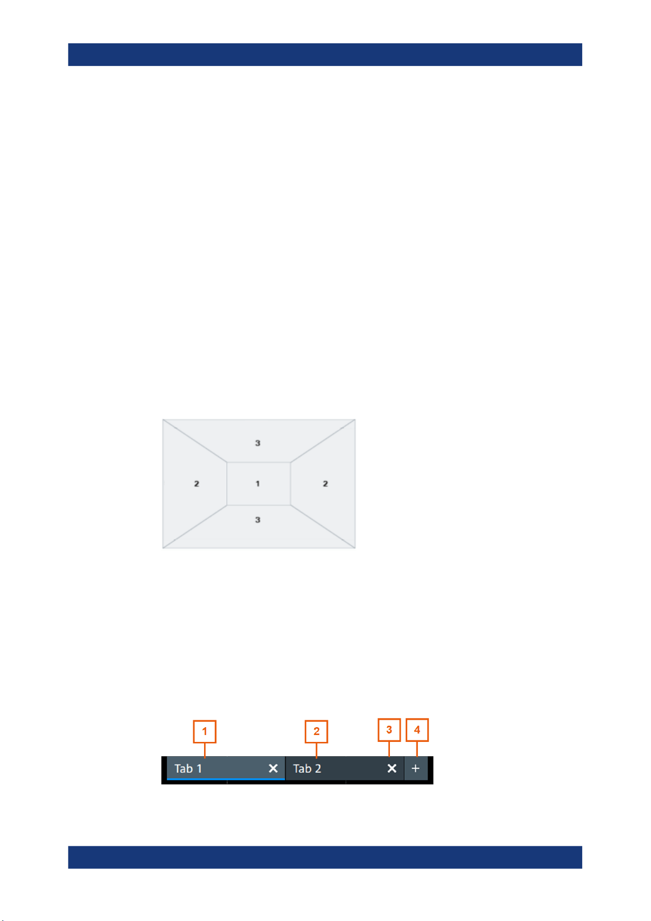
Operating the instrument
R&S
®
MXO 5 Series
54User Manual 1802.3369.02 ─ 02
To switch off a waveform
► Do one of the following:
● Tap the "Delete" icon in the toolbar, and then signal icon of the waveform.
You can also tap the waveform directly. If several waveforms overlap or lie
close together, a selection list is shown.
● To switch off a minimized waveform, tap the "Close" icon in the upper right cor-
ner of the signal icon.
● If the waveform is an input channel:
– Disable "Show channel" in the "Vertical" > "Setup" tab.
– Select the channel. Then press its channel key twice.
Remote command: CHANnel<ch>:STATe on page 464
4.5 Rohde & Schwarz SmartGrid
The Rohde & Schwarz SmartGrid helps to create and arrange the diagrams on the
screen with drag&drop. The diagram layout depends on the position where you drop
the signal icon, in relation to an existing diagram.
Figure 4-7: SmartGrid positions
1 = In the existing diagram, overlay of signal
2 = New diagram on the left or right
3 = New diagram above or below
The diagram configuration is deleted when you use [Preset] or *RST.
Working with layouts
A SmartGrid configuration of one or more diagrams is called "tab" or "layout". You can
define several layouts and switch between them.
Rohde
& Schwarz SmartGrid
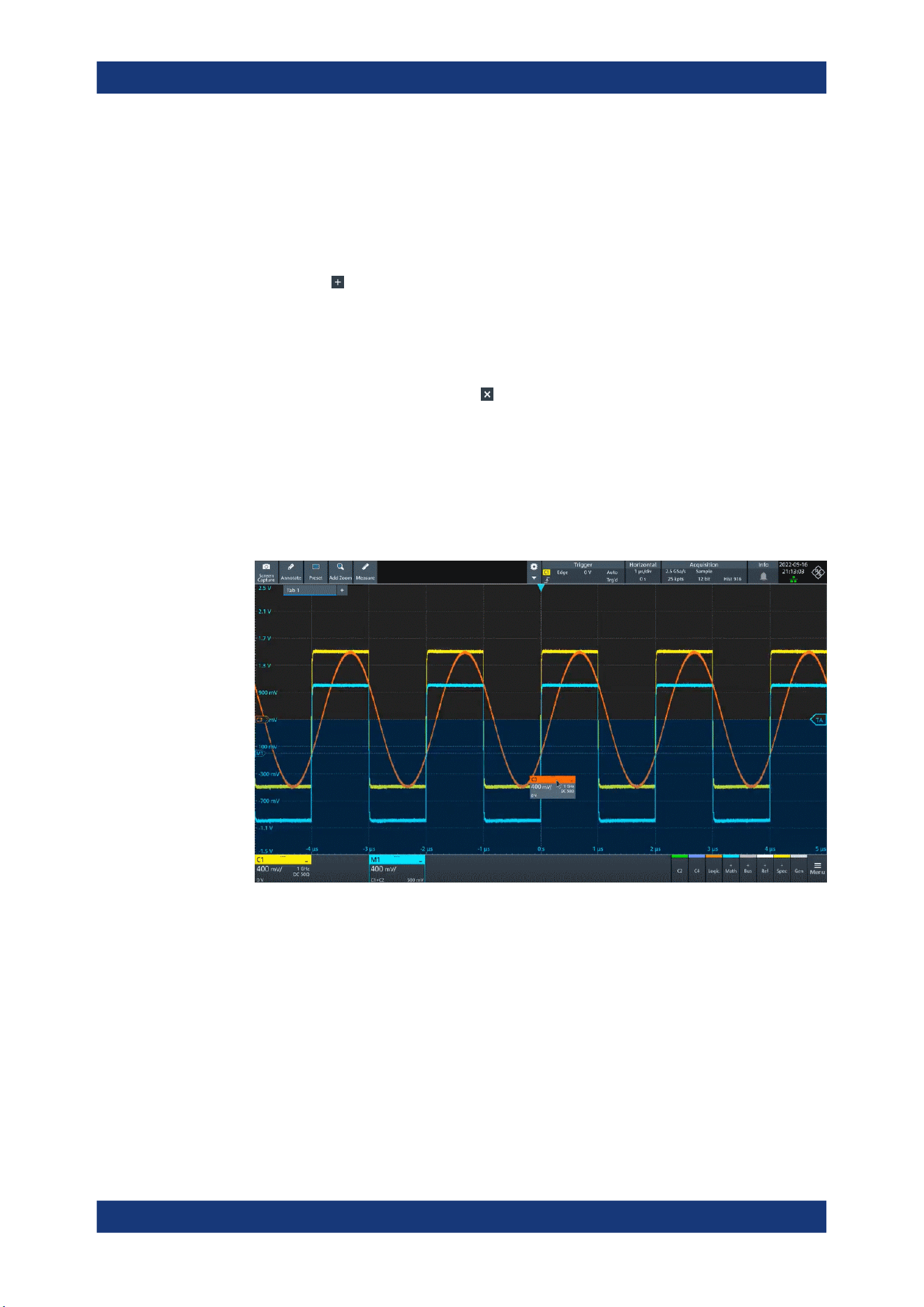
Operating the instrument
R&S
®
MXO 5 Series
55User Manual 1802.3369.02 ─ 02
1 = Tab 1 (layout 1, blue underline indicates that the set is currently displayed)
2 = Tab 2 (layout 2)
3 = Tap to remove a layout
4 = Tap to add a layout
You can add up to four layouts at the upper left corner of the screen:
1.
Tap on the icon next to the layout.
A new layout is created.
2. To change the layout name, touch and hold the tab name. The on-screen keyboard
opens to enter the new name. Names must be unique.
3.
To remove the layout, tap on the
next to the layouts title.
To arrange a waveform using the SmartGrid
1. Select the layout that you want to rearrange.
2. Drag the signal icon to the diagram area, and move it around.
The Rohde & Schwarz SmartGrid appears and a blue or highlighted area shows
where the waveform will be placed.
3. Drop the waveform in the target area.
The waveform appears in an existing or in a new diagram, and it is selected for fur-
ther actions.
4. To change the size of a diagram, touch the border between two diagram frames
and drag it to the required position.
5. If a diagram is empty, you see a trash can icon in the diagram center. Use the icon
to delete the diagram, or drag waveform icons into the diagram.
Remote commands: see Chapter 17.7.2, "SmartGrid", on page 443
Rohde
& Schwarz SmartGrid

Operating the instrument
R&S
®
MXO 5 Series
56User Manual 1802.3369.02 ─ 02
4.6 Toolbar
The toolbar provides direct access to important control and measurement functions.
By default, the toolbar shows the most frequently used functions. You can configure the
content of the toolbar, see Chapter 4.6.2, "Configuring the toolbar", on page 56.
4.6.1 Using the toolbar
Using the toolbar is easy and straightforward.
Some of the toolbar functions are one-click actions. These actions are performed
immediately when you tap the icon.
Other toolbar functions are analyzing functions. These actions are interactive actions.
To use analyzing functions (interactive actions)
1. Tap the icon of the function in the toolbar.
2. Check and adjust the settings in the overlay menu.
3. Select the source waveform if needed. For zoom, drag a rectangle, or tap the dia-
gram to define the zoom area.
4.
If the overlay menu does not close automatically, tap the
icon.
4.6.2 Configuring the toolbar
You can configure the content of the toolbar so that only the required functions are dis-
played. The toolbar configuration is part of the user preferences. It is retained when
you switch off and on the instrument, and you can save it in the user preferences and
user-defined preset.
1. To open the toolbar configuration, tap the icon in the toolbar:
2. Select the required toolbar functions:
a) In the "Show/Hide tools" section, disable all functions that you do not need.
b) In the "Show/Hide tools" section, enable the functions that you want to add to
the toolbar.
c) In the "Drag to rearrange tools" section, move the icons to arrange them as
required.
3. To empty the toolbar, select "Deslect all".
Toolbar
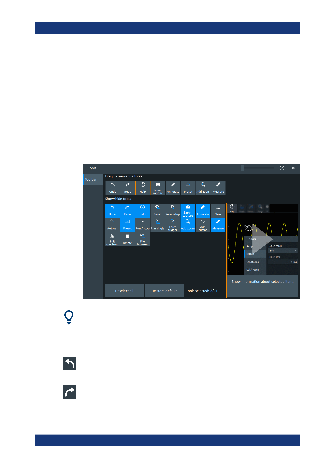
Operating the instrument
R&S
®
MXO 5 Series
57User Manual 1802.3369.02 ─ 02
4. To get the factory configuration of the toolbar, select "Restore default".
A detailed description of the toolbar functions is given in Chapter 4.6.3, "Toolbar func-
tions", on page 57.
Remote commands:
●
DISPlay:TOOLbar:COUNt? on page 449
●
DISPlay:TOOLbar:DESelect on page 449
●
DISPlay:TOOLbar:RESTore on page 449
4.6.3 Toolbar functions
This section describes all toolbar functions in detail.
You can configure the content of the toolbar, see Chapter 4.6.2, "Configuring the tool-
bar", on page 56.
The following list describes at first the default toolbar functions and then the additional
functions.
Undo
Undoes the last setting actions step by step. Some actions cannot be revoked: locking
the touchscreen with [Touch Lock], and saving data.
Redo
Recovers the undo steps in reverse order.
Toolbar
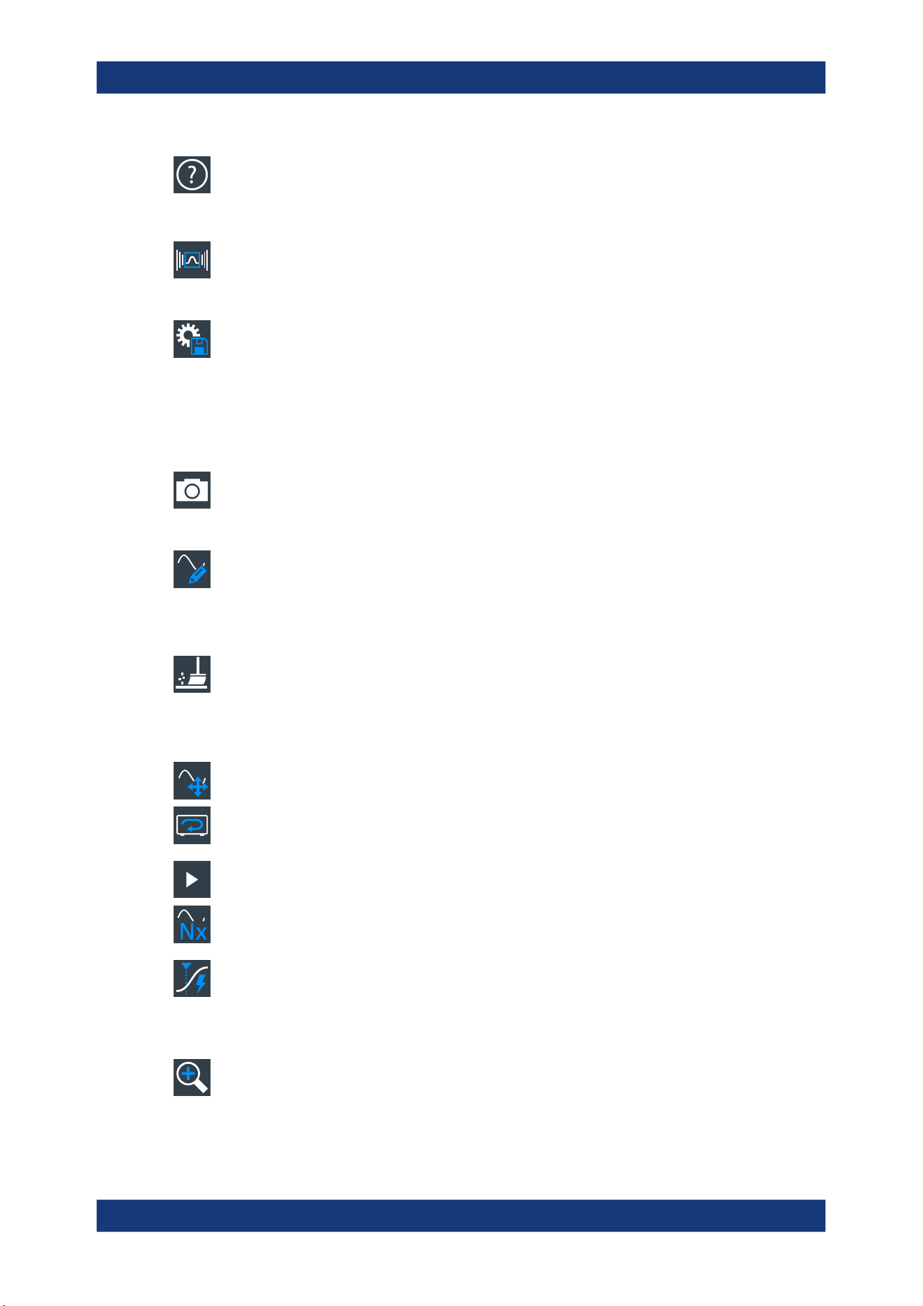
Operating the instrument
R&S
®
MXO 5 Series
58User Manual 1802.3369.02 ─ 02
Help
Enables the context help display. The help window opens when you tap a parameter.
See also: "To display the context help" on page 67.
Recall
Opens a window to select and load instrument settings that were previously stored in a
saveset.
Save setup
Saves the current instrument settings in a saveset.
You can reload the saveset using the "Recall" toolbar icon, or using "Menu" >"Save/
Recall" > "Recall" tab > "Saveset".
The filename is created according to the autonaming pattern, defined in "Menu" > "Set-
tings" > "Save / Recall" > "Autonaming" tab.
Screen capture
Saves a screenshot of the current display using the settings defined in "Menu" >"Save/
Recall" > "Save" tab > "Screenshot".
Annotate
Displays drawing tools for marking areas on the diagram, and for adding text. You can
also select the color.
See also: Chapter 4.10, "Adding annotations", on page 63.
Clear
Deletes all measurement results including all waveforms and statistics.
Remote command:
DISPlay:CLR on page 456
Autoset and Preset
Performs an autoset, or a preset to a default state. The icons have the same function-
ality as the corresponding keys on the front panel. They are useful when you operate
the instrument remotely.
Run / stop and Run single
Starts and stops the continuous acquisition, or starts a defined number of acquisition
cycles. The icons have the same functionality as the corresponding keys on the front
panel. They are useful when you operate the instrument remotely.
Force trigger
Starts an immediate single acquisition. If the acquisition is running in normal mode and
no valid trigger occurs, use "Force trigger" to confirm that a signal is available. Then
you can use the displayed waveform to determine how to trigger on it.
Add zoom
Adds a zoom diagram, an area of the acquired waveform which is visually enlarged.
Click a diagram to create a zoom or draw a rectangle to define the range of the zoom.
Toolbar
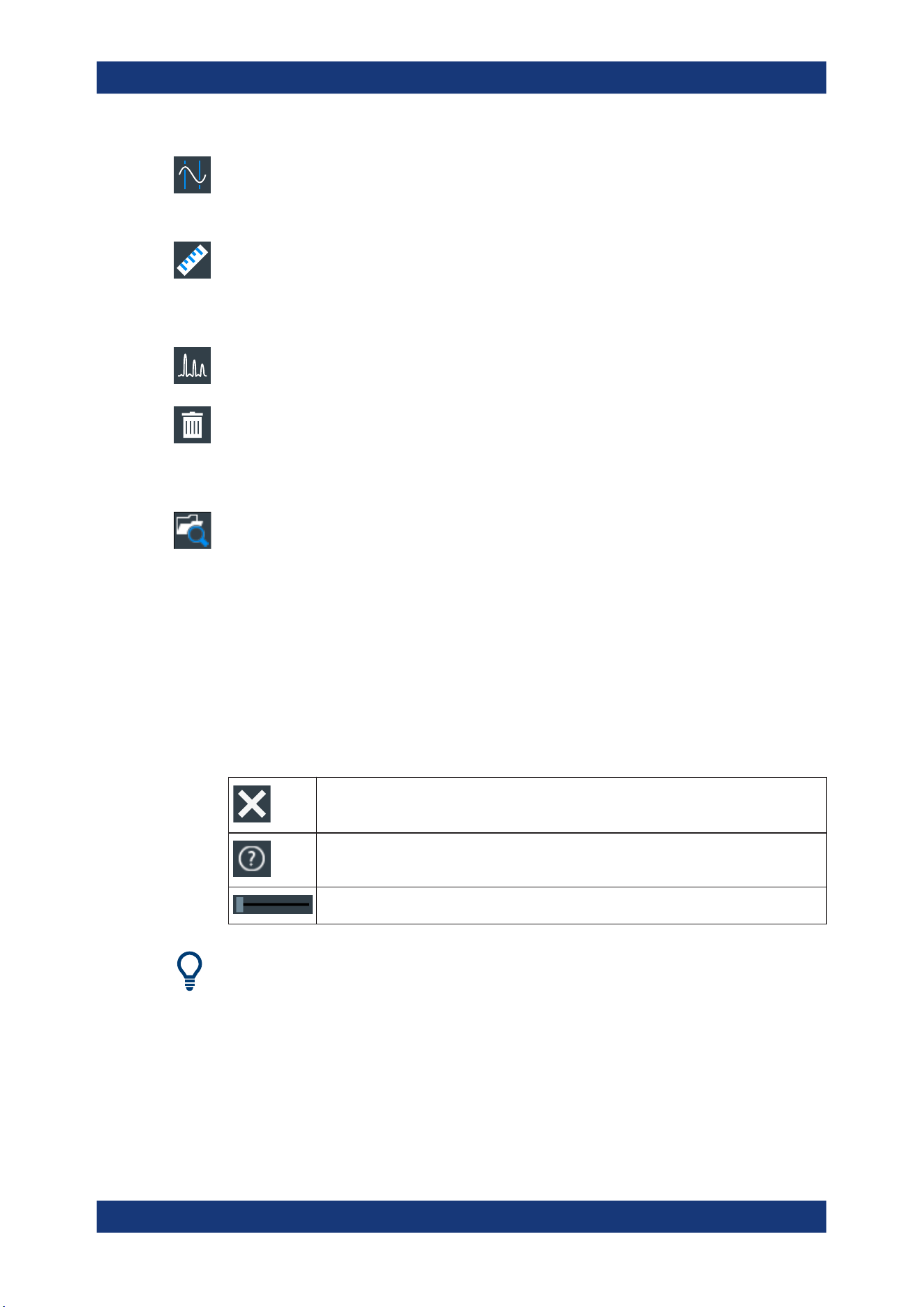
Operating the instrument
R&S
®
MXO 5 Series
59User Manual 1802.3369.02 ─ 02
Add cursor
Adds a cursor set. Select the cursor type and the source to be measured.
See also: Chapter 9.1, "Cursor measurements", on page 184.
Measure
Adds one or more measurements to the waveform.
Tap the icon, and select the category and the measurements in the overlay menu.
Select the waveform to be measured, and close the overlay menu.
Edit spectrum
Edit the existing spectrum settings in the overlay menu.
Delete
Removes waveforms, diagrams and zooms from the display.
Tap the "Delete" icon. A recycle bin icon marks all objects that can be deleted. Tap this
icon to remove an object. Tap the "Delete" icon again to disable the function.
File browser
Opens the file browser dialog.
See also: Chapter 12.5, "File browser dialog", on page 283.
4.7 Using dialog boxes
All functionality is provided in dialog boxes as known from computer programs. You
can control the instrument intuitively with the touchscreen. This section provides an
overview of the accessing methods and describes how to use the dialog boxes.
Each dialog box has three icons in the upper right corner:
Closes the dialog box
Opens the help window for the dialog
Shift sideways to change the transparency of the dialog box
For direct access to important control and measurement functions, use the toolbar, see
Chapter 4.6, "Toolbar", on page 56.
To open a dialog box
► Perform one of the following actions:
● Open the "Menu", and select the menu entry.
● Press the function key on the front panel.
Using dialog boxes

Operating the instrument
R&S
®
MXO 5 Series
60User Manual 1802.3369.02 ─ 02
●
Double-tap a result icon, or tap the icon in a result box to open the corre-
sponding dialog box.
● To open the "Vertical" dialog box of a waveform, tap the signal icon.
● Tap the "Horizontal", "Acquisition" or "Trigger" label to open the corresponding
dialog box.
To close a dialog box
► Tap the "Close" icon in the upper right corner.
4.8 Entering data
To set parameter values and enter other data, you use the various knobs and the on-
screen keypad or keyboard.
Using scale, position and level knobs
The instrument has dedicated rotary knobs to set vertical and horizontal positions and
scale, and the trigger level.
1. Turn the knob to change the value.
2. Press the knob:
● [Scale]: to toggle the increment.
● [Position]: to set to zero.
● [Level]: to set the trigger level to 50% of the signal.
To enter values with the on-screen keypad
For data input in dialog boxes, the touchscreen provides an on-screen keypad to enter
numeric values and units. For text input, the on-screen keyboard with English key lay-
out is used.
1. Double-tap the entry field. The on-screen keypad opens.
Entering data
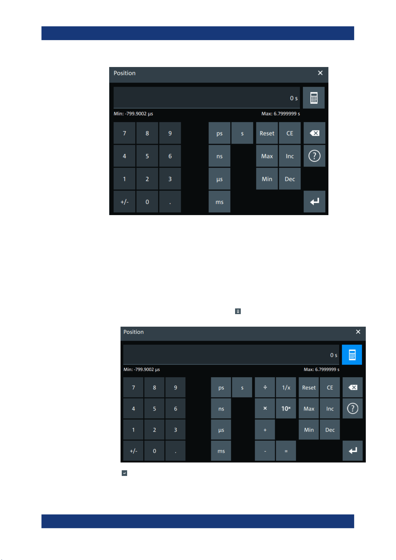
Operating the instrument
R&S
®
MXO 5 Series
61User Manual 1802.3369.02 ─ 02
2. Enter the numeric value using the following methods:
● To use the default value, tap "Reset" (if available).
● To get the value that was used before the keypad was displayed, tap "CE".
● To use the minimum or maximum value, tap "Min" or "Max", respectively.
● To increase the displayed value in fixed steps, tap "Inc".
To decrease the value in fixed steps, tap "Dec".
● To enter a user-defined value, tap the numbers and complete the entry by tap-
ping the unit button.
– "±" changes the sign of the value.
●
To calculate a value, tap the calculator
to display the arithmetic operators.
Use the displayed fields to calculate your values.
3.
Tap
to complete the entry.
Entering data
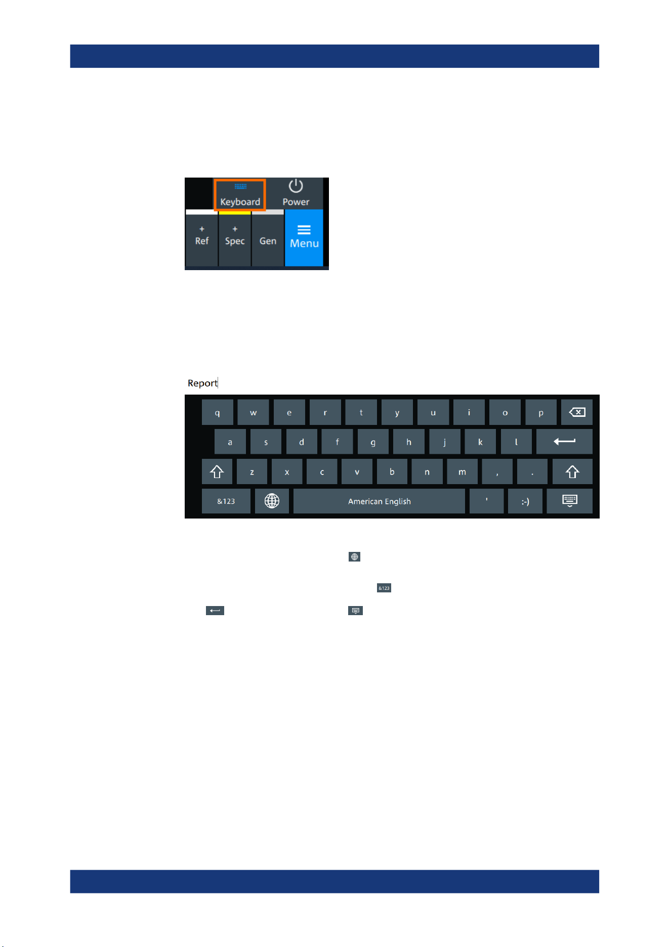
Operating the instrument
R&S
®
MXO 5 Series
62User Manual 1802.3369.02 ─ 02
To enable the on-screen keyboard
1. Tap "Menu".
2. Tap on "Keyboard" to enable the on-screen keyboard.
If the on-screen keyboard is enabled, the keyboard icon is colored blue. If it is dis-
abled, the color is white.
To enter data with the on-screen keyboard
1. Double-tap the entry field to open the on-screen keyboard.
2. Enter the text as you would on a normal keyboard.
●
To change the language, tap . The current language is shown on the blank
key.
●
To display numbers and signs, tap .
3.
Tap
to complete the entry or to minimize the keyboard.
4.9 Displaying results
The results of measurements, protocol decoding and others are displayed immediately.
The font size can be adjusted.
To arrange the results on the display
1. Touch and hold the "....." field on top of the results table.
Displaying results
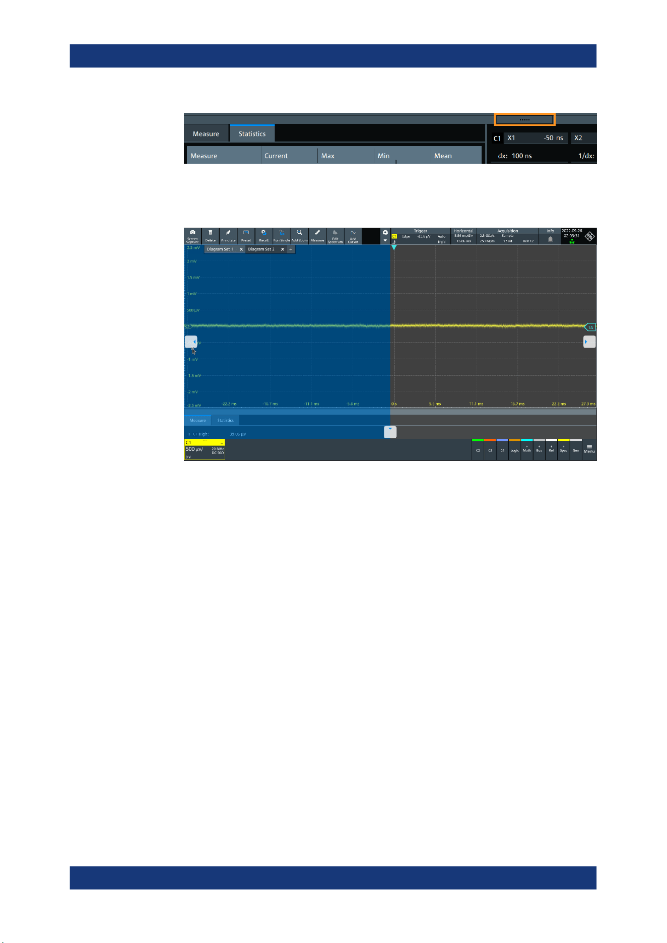
Operating the instrument
R&S
®
MXO 5 Series
63User Manual 1802.3369.02 ─ 02
2. Drag on the screen. The SmartGrid indicates where the result table can be placed.
Drop the box on one of the buttons. The results are shown at the left the right, or
below the diagrams.
To open the corresponding settings
► Double-tap one of the result values.
The corresponding dialog opens.
To adjust the font size of results
1. Open the "Menu" > "Settings" > "Appearance" dialog.
2. Select the "Dialogs" tab.
3. Set the "Result dialog" > "Font size".
4.10 Adding annotations
The R&S MXO 5 provides an easy way to add annotations to the screen. With the tool-
bar "Annotate" you can add text, forms or even draw.
To add an annotation
1. On the toolbar, tap on the "Annotate" icon.
Adding annotations
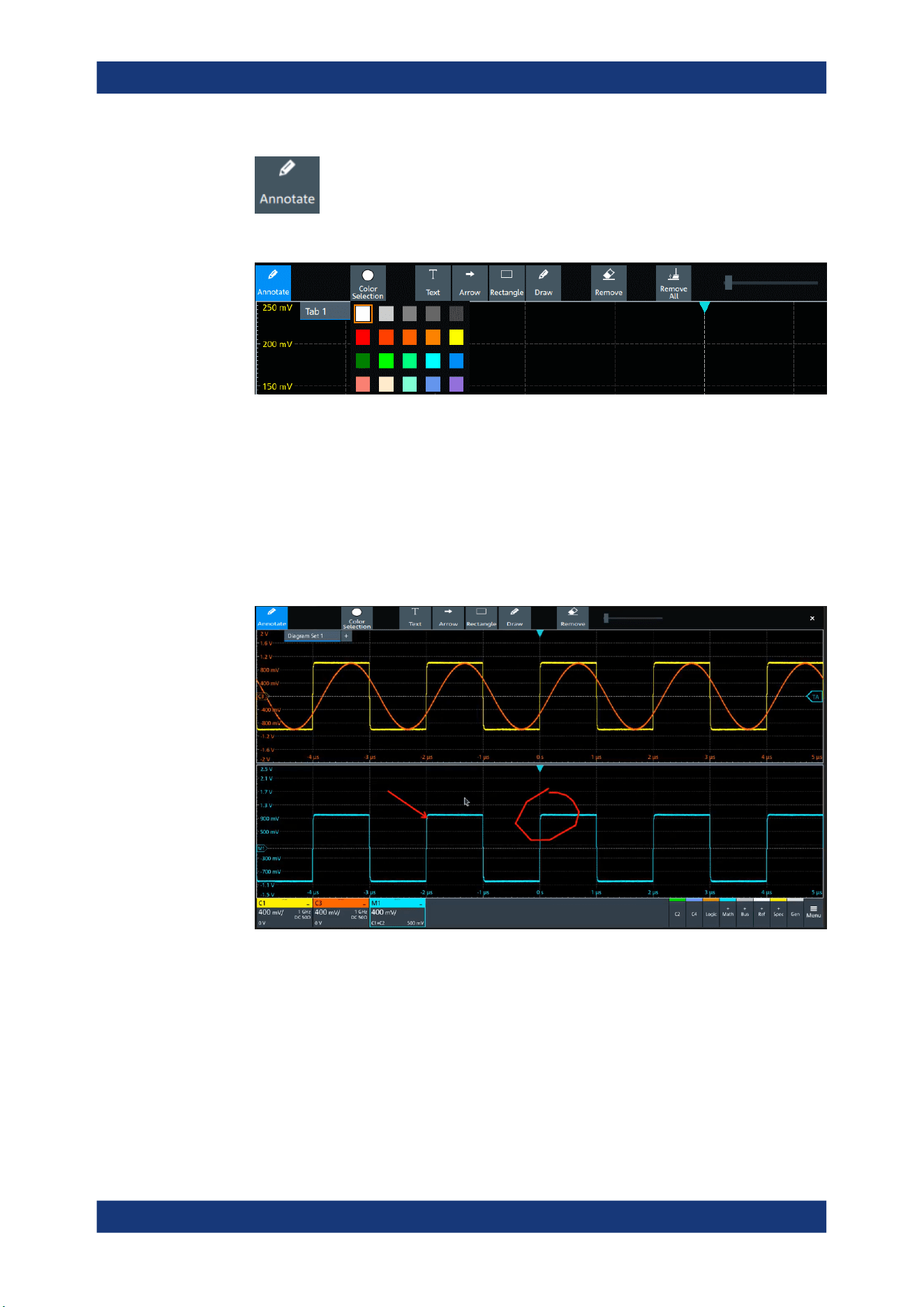
Operating the instrument
R&S
®
MXO 5 Series
64User Manual 1802.3369.02 ─ 02
The annotation overlay menu opens.
2. Tap "Color selections" and select the color that you want to use for your annota-
tions.
3. Add one or more of the following:
● One of the predefined forms: "Arrow" or "Rectangle"
● "Text": adds a text element to the screen and opens on-screen keyboard. You
can change the text later, by tapping on an existing annotation and typing in the
new text.
● "Draw": you can draw any form on the screen.
4. To move one of the annotations, tap on it and drag it to the required position.
To remove an annotation
1. In the "Annotate" overlay menu, tap on "Remove".
2. Tap on any existing "Arrow", "Rectangle" or "Text" annotation to remove it.
3. The "Remove" function, acts as an eraser on drawings: it enables you to erase only
certain parts of your drawing. Drag your finger over any part of your drawing to
erase it.
Adding annotations

Operating the instrument
R&S
®
MXO 5 Series
65User Manual 1802.3369.02 ─ 02
4. To remove all annotations from the screen, tap on "Remove All".
4.11 Information and notifications
The oscilloscope provides various information:
●
Instrument information, e.g. connection status, firmware version
●
Notifications, e.g. status messages
●
Progress information, e.g. for long acquisitions, data saving
Instrument information
In the upper right corner of the screen, you see the Rohde & Schwarz logo, date and
time, the symbolic information on LAN connection and the notifications status.
► To see the instrument information, select the Rohde & Schwarz logo.
You can find information about the instrument model, bandwidth, network settings,
firmware version and operating time.
► To hide the date and time or change the display format, select the date/time dis-
play.
Notifications
Notifications are status messages, information on mismatching settings and similar
information. They are displayed for a few seconds and saved.
The color of the dot before the text indicates the severity: gray for information, orange
for warnings, and red for errors.
► To read the notifications, select "Notification".
Information and notifications
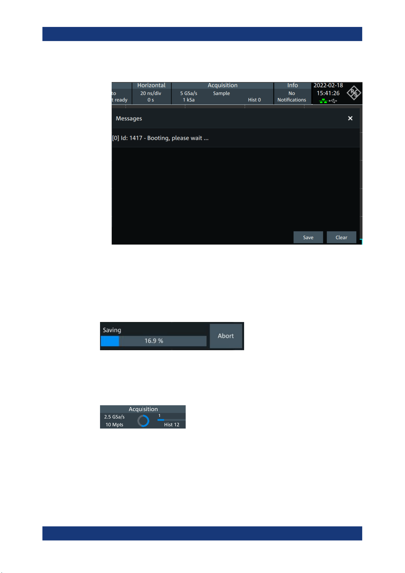
Operating the instrument
R&S
®
MXO 5 Series
66User Manual 1802.3369.02 ─ 02
You can save or delete the list of notifications.
Progress information
If an acquisition, operation or process takes more time until results are displayed, a
progress bar or symbol indicates that a process is running.
The progress of saving operations and update or creation of a reference waveform is
shown in a progress bar. You can cancel the process. A notification informs about the
result.
Figure 4-8: Progress bar for saving waveform data
The progress of running acquisitions is shown in the acquisition label. A circle indicates
the state of the current, incomplete acquisition. Progress in roll mode, average mode
and single acquisition with N > 1 is indicated by a progress bar and counter.
Figure 4-9: Progress of incomplete long acquisition in average mode, Run Single = 5, first acquisition
is finished
Information and notifications

Operating the instrument
R&S
®
MXO 5 Series
67User Manual 1802.3369.02 ─ 02
4.12 Getting user assistance
If you need information on the instrument's functionality, you can use the instrument
help. It provides contextual information on a setting or dialog. If the help window is
open, you can browse and search for further information using links, table of contents,
and search.
4.12.1 Displaying help
To display the context help
1. Enable the "Help" icon on the toolbar.
2. Tap the parameter for which you need information.
The "Help" window opens and displays the comprehensive description and the cor-
responding remote command. You can browse the help for further information.
To open a dialog help
1. Open a dialog.
2.
Tap the "Help" icon in the dialog header.
3. Tap a subtab or menu item.
The help window opens with the dialog help page, where you can select the topics.
4.12.2 Using help
You can find a specific information and navigate the contents by following means:
●
Table of contents
●
Buttons in the help window title:
– "Home": Go to the start page
– "Back", "Forward": Browse the pages that you visited before
●
Search with filter:
Getting user assistance

Operating the instrument
R&S
®
MXO 5 Series
68User Manual 1802.3369.02 ─ 02
– Enter the word to be found, or a phrase in quotes.
– Tap the filter icon and select the information type.
Getting user assistance
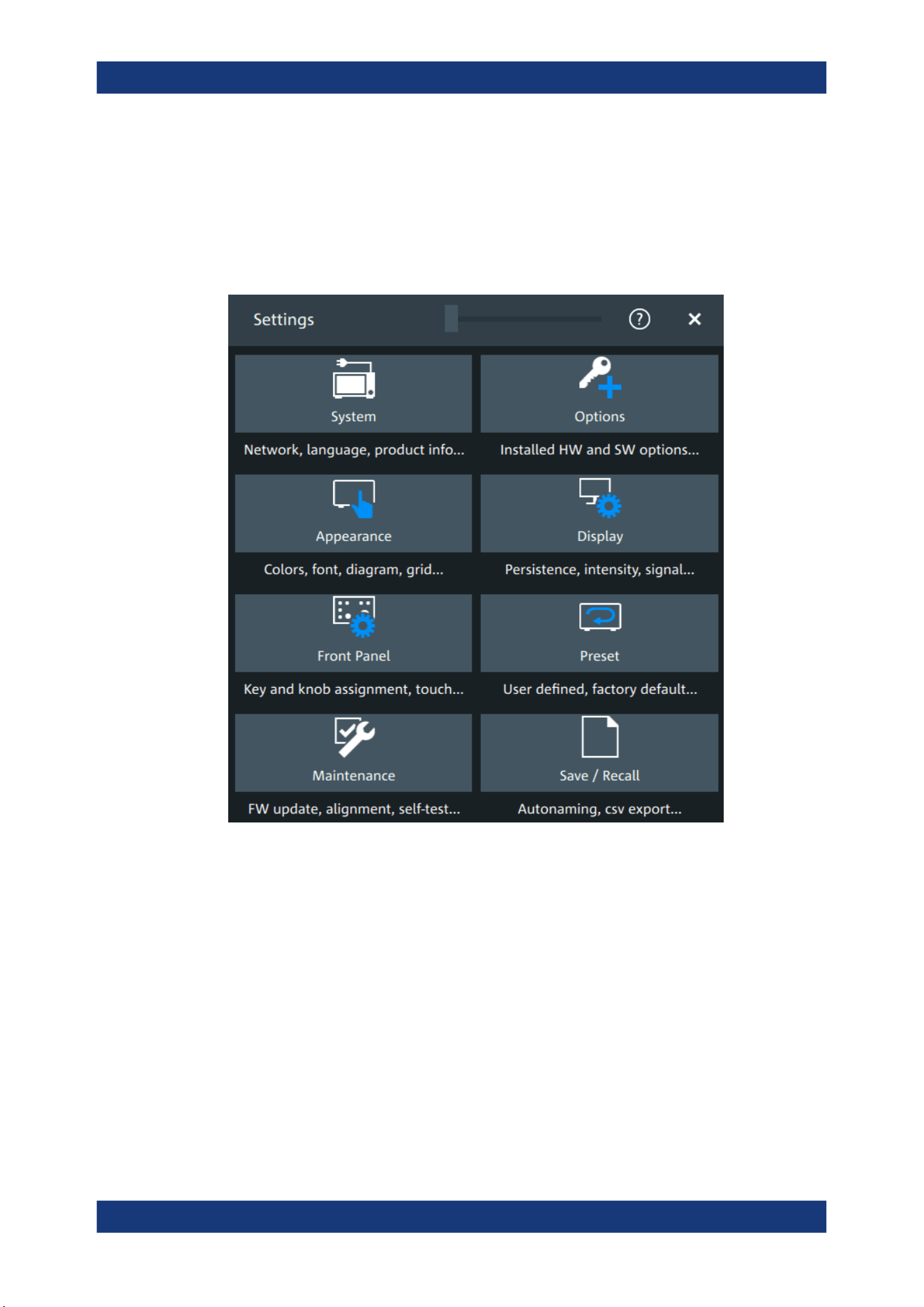
Instrument setup
R&S
®
MXO 5 Series
69User Manual 1802.3369.02 ─ 02
5 Instrument setup
Access: "Menu" > "Settings".
In the "Settings" dialog, you can adapt various instrument settings to your require-
ments, such as language, display appearance, and assign functions to some keys.
The following settings and procedures are described in the current section:
● System settings.......................................................................................................70
● Option settings........................................................................................................ 76
● Appearance settings............................................................................................... 78
● Display settings.......................................................................................................84
● Front panel settings.................................................................................................87
● Preset setup............................................................................................................88
● Maintenance settings.............................................................................................. 91
● Save / recall............................................................................................................ 95
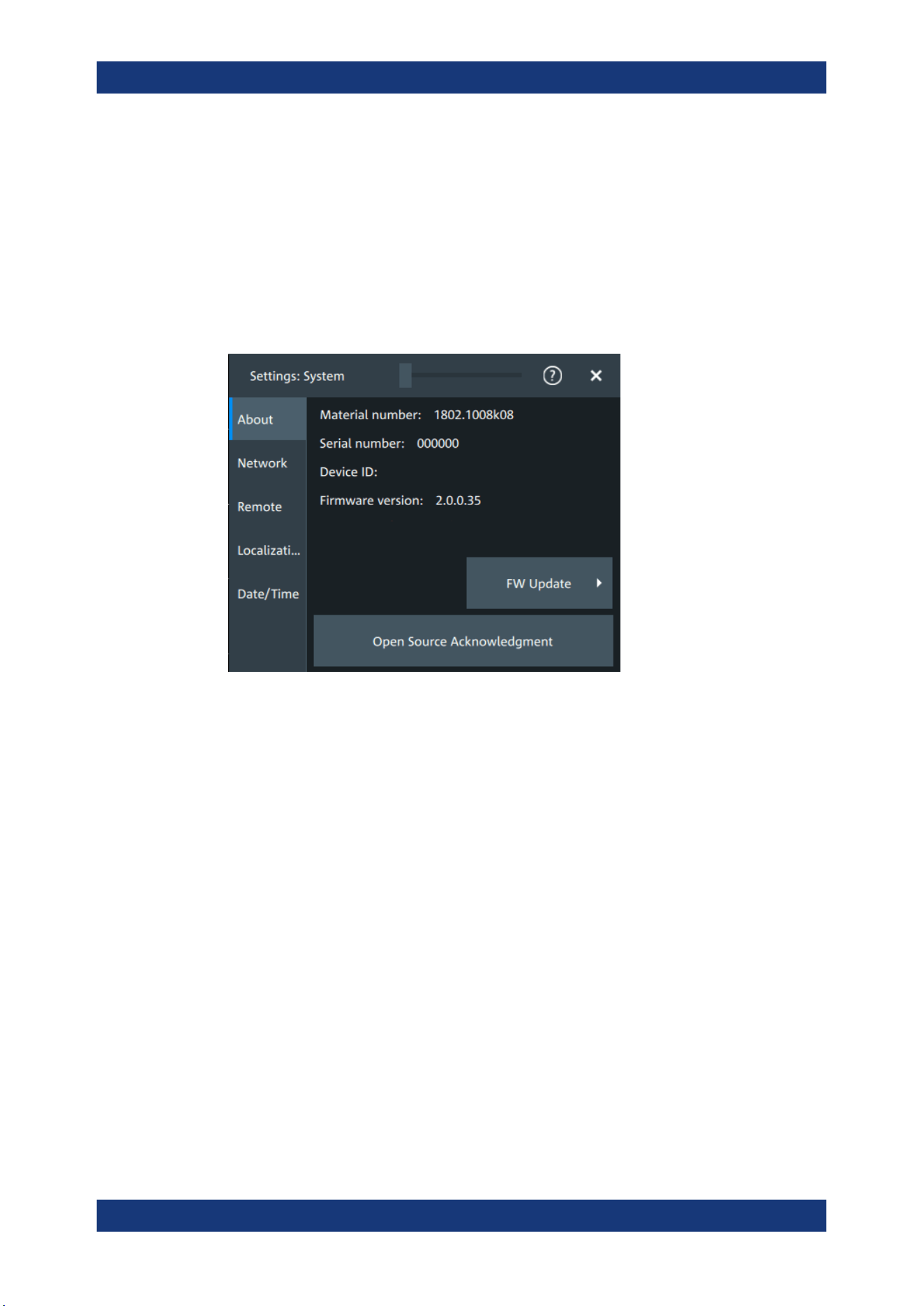
Instrument setup
R&S
®
MXO 5 Series
70User Manual 1802.3369.02 ─ 02
5.1 System settings
In the "Settings" > "System" dialog box, you find all instrument, firmware and network-
related information. Here you can also set the language that is used in the dialogs.
5.1.1 About settings
Access: "Menu" > "Settings" > "System" > "About".
Instrument
Displays general information about the instrument, including:
●
"Material number"
●
"Serial number"
●
"Device ID"
●
"Firmware version"
Remote command:
*IDN? on page 436
FW update
Opens the "FW update" dialog box. See Chapter 5.7.1, "Firmware update",
on page 91.
Open source acknowledgment
Displays the "Open Source Acknowledgment" document.
5.1.2 Network settings
Access: "Menu" > "Settings" > "System" > "Network".
System settings
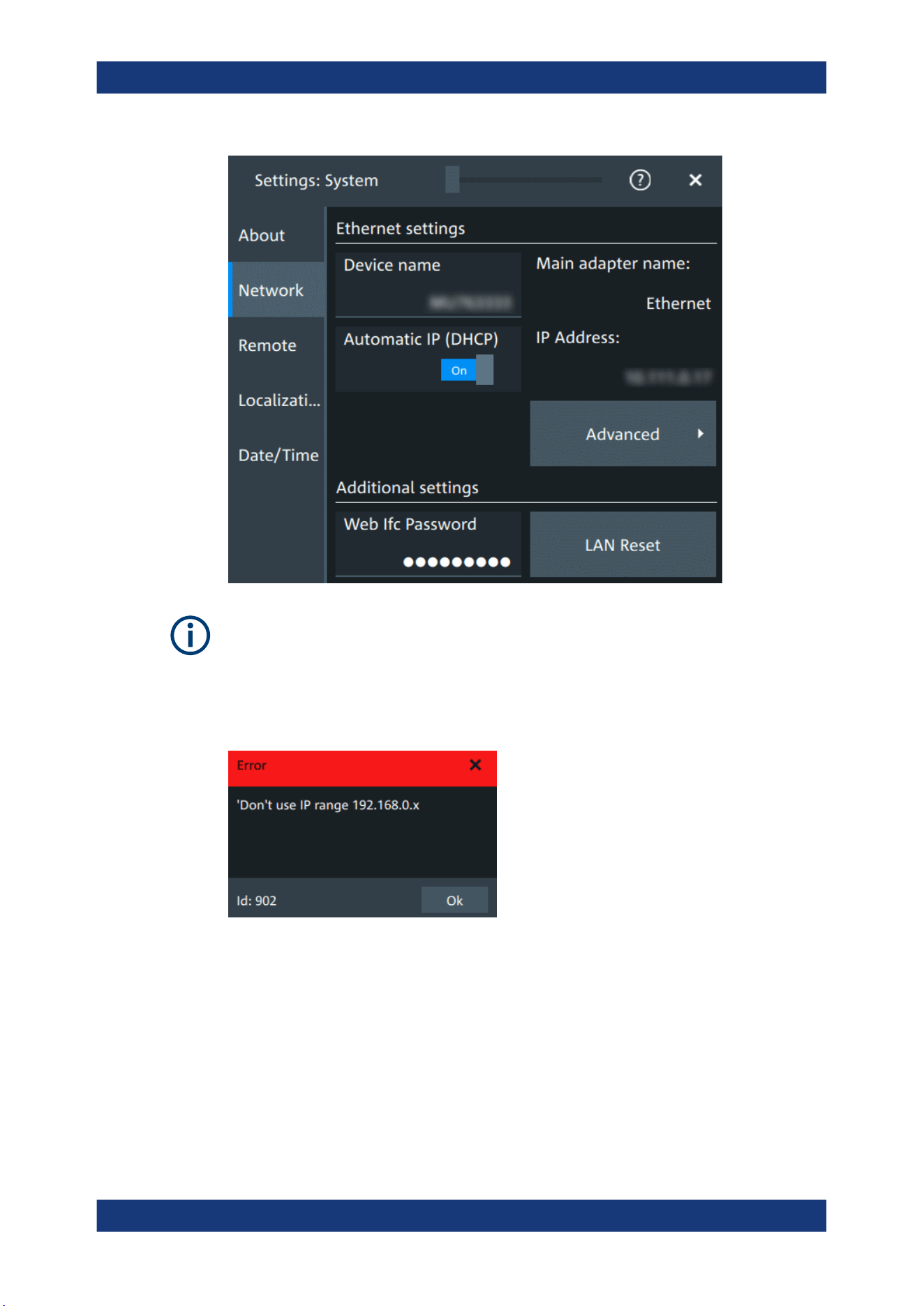
Instrument setup
R&S
®
MXO 5 Series
71User Manual 1802.3369.02 ─ 02
Ensure that you do not use the IP address range 192.168.0.x to avoid internal address
conflict.
Setting up a manual IP address within this range is rejected by the firmware. If the
automatic DHCP server assigns an IP address within this range, the instrument is not
reachable from this network.
An error message is displayed, if the firmware detects an IP address error:
Device name
Indicates the currently defined device name. This value is required to configure the
instrument for work in a network.
NOTICE! Risk of network problems. Incorrect configuration of the device name can
create network problems. Consult your network administrator before changing the
name.
Remote command:
SYSTem:COMMunicate:NET[:HOSTname] on page 441
System settings

Instrument setup
R&S
®
MXO 5 Series
72User Manual 1802.3369.02 ─ 02
Automatic IP (DHCP)
If enabled, the IP address of the oscilloscope is obtained automatically.
IP address
Shows the current IP address of the instrument. If "Automatic IP (DHCP)" is "Off", you
can change the IP address here. For complete manual configuration, select
"Advanced". See also: Chapter 16.1, "Connecting the instrument to the network
(LAN)", on page 407.
Web Ifc Password
Password for LAN configuration. The default password is LxiWebIfc.
LAN reset
Resets the LAN configuration to its default settings using the network configuration
reset mechanism (LCI) for the instrument.
The LAN settings are configured in the "Advanced" dialog, or using the instrument's
web browser (see Chapter 16.2, "Web interface", on page 410).
Advanced
Opens a dialog box to configure the network connection.
System settings
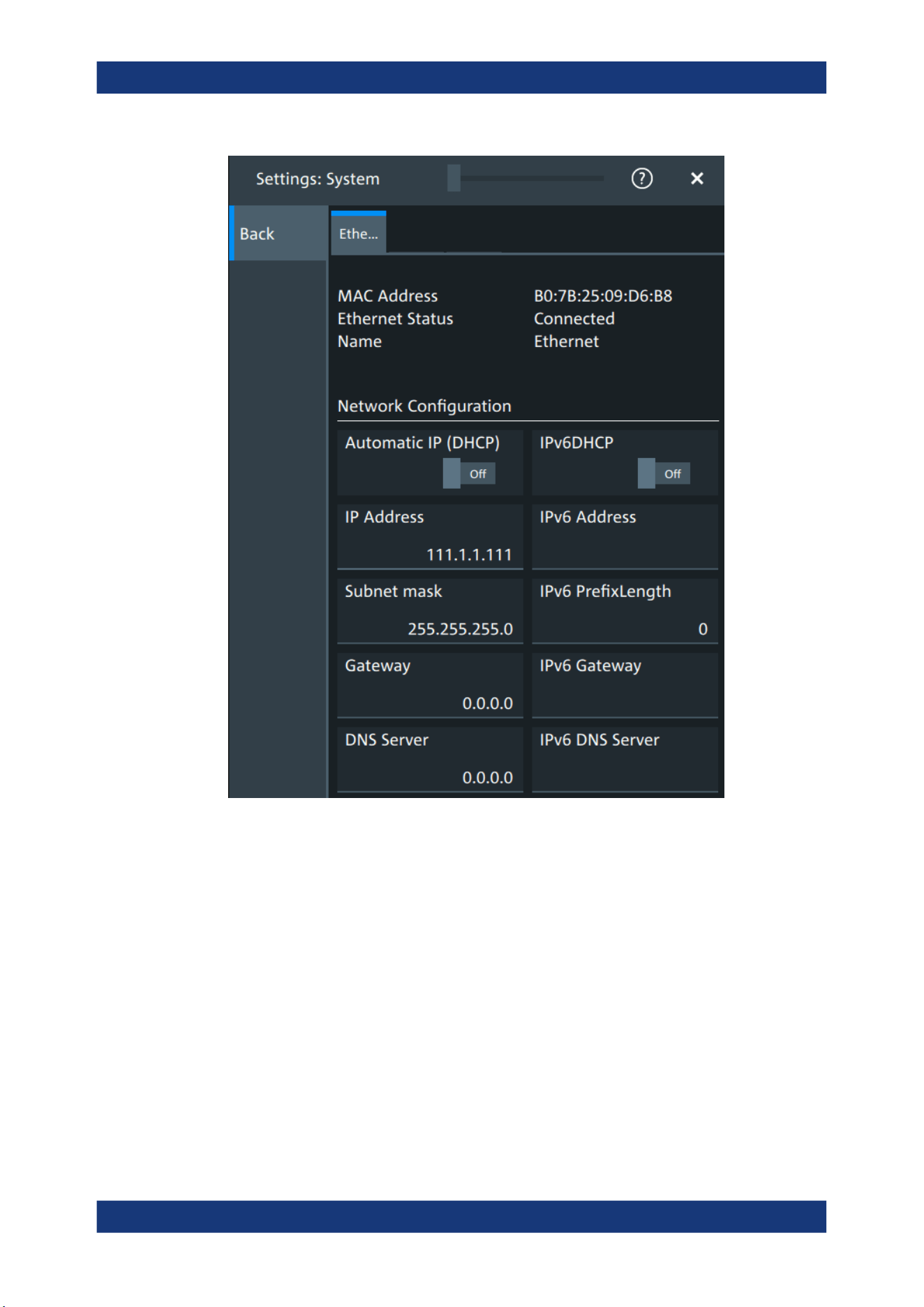
Instrument setup
R&S
®
MXO 5 Series
73User Manual 1802.3369.02 ─ 02
You need these settings to configure the LAN connection manually, without DHCP.
NOTICE! Connection errors can affect the entire network. You must assign valid
address information before connecting the instrument to the LAN. Contact your net-
work administrator to obtain a valid IP address and other connection data.
See also: Chapter 16.1, "Connecting the instrument to the network (LAN)",
on page 407.
5.1.3 Remote settings
Access: "Menu" > "Settings" > "System" > "Remote".
System settings
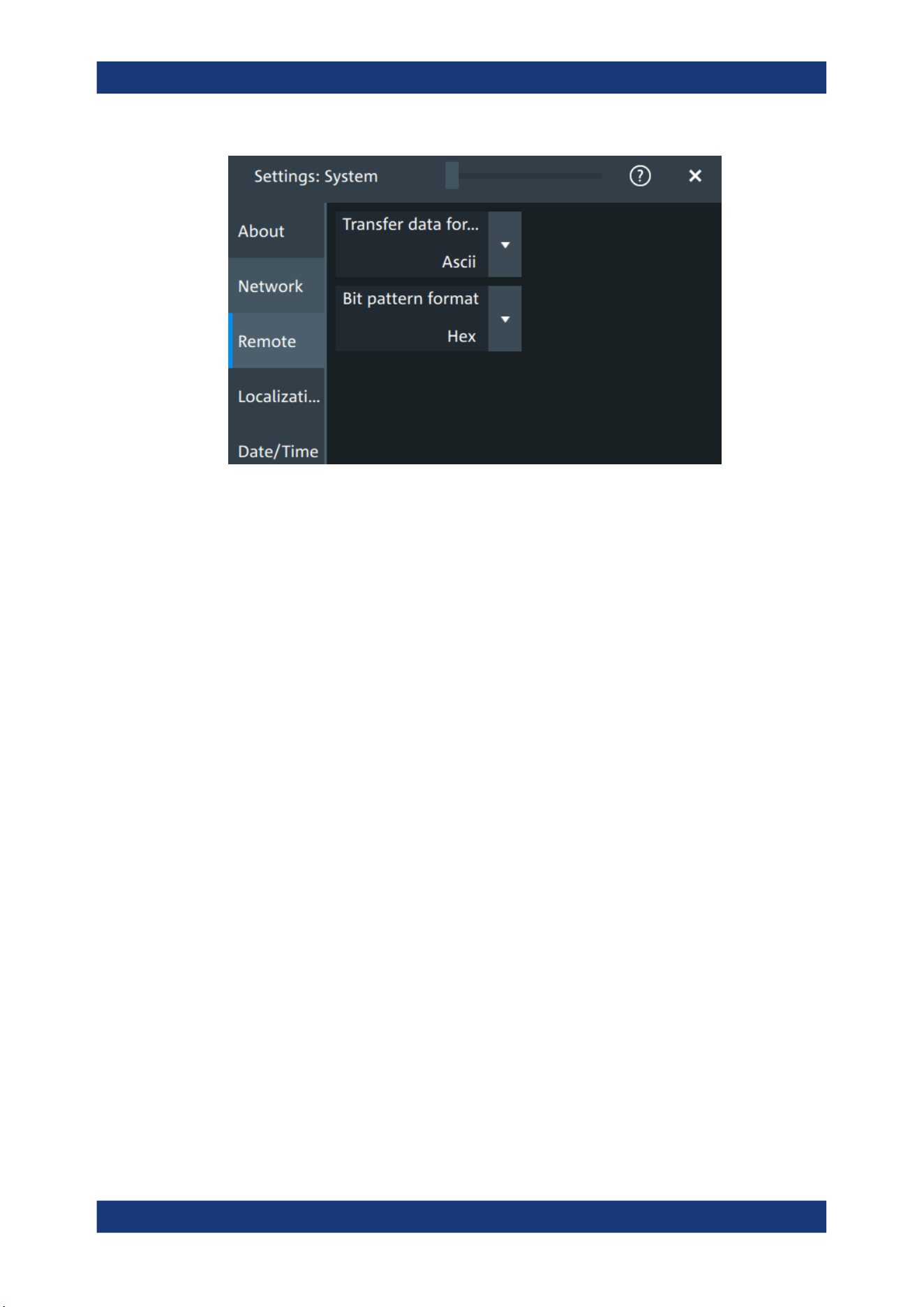
Instrument setup
R&S
®
MXO 5 Series
74User Manual 1802.3369.02 ─ 02
The following settings are required for remote control of the instrument via a connected
computer.
Transfer data format
Selects the data format that is used for transmission of waveform data from the instru-
ment to the controlling computer.
Waveform data can be retrieved using the following commands:
●
DIGital<m>:DATA[:VALues]?
"Ascii"
Data values are returned in ASCII format as a list of comma-separa-
ted values in floating point format.
"FLOAT"
Binary format. Up to 7 significant digits are stored. If there are more
than 7 digits, the number is rounded off.
"DOUBLE"
Binary format. Up to 15 significant digits of the numbers are stored.
"INT8/16/32"
Signed integer data with length 8/16/ 32 bit.
Remote command:
FORMat[:DATA] on page 439
Bit pattern format
Sets the format for all bit pattern queries.
Remote command:
FORMat:BPATtern on page 440
5.1.4 Localization settings
Access: "Menu" > "Settings" > "System" > "Localization".
System settings
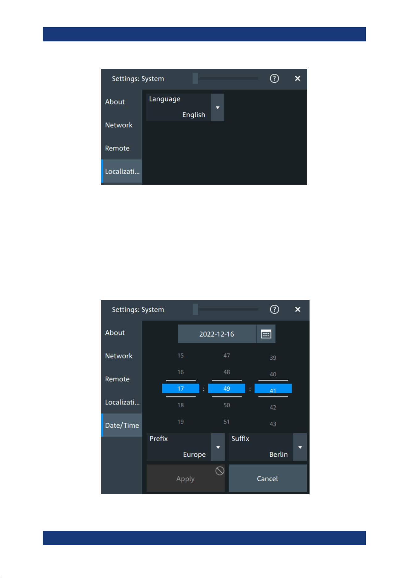
Instrument setup
R&S
®
MXO 5 Series
75User Manual 1802.3369.02 ─ 02
Language
Selects the language in which the dialog boxes, result boxes and other screen informa-
tion is displayed. You can change the instrument language while the instrument is run-
ning.
Available languages are, for example, English, German, French, Japanese. For a com-
plete list of supported languages, refer to the data sheet.
5.1.5 Date and time settings
Access: "Menu" > "Settings" > "System" > "Date/time".
System settings

Instrument setup
R&S
®
MXO 5 Series
76User Manual 1802.3369.02 ─ 02
The instrument uses the system time of the operating system, but you can change date
and time for the R&S MXO 5 firmware.
1. To change the date:
a) Tap the date button.
b) Select the date in the calendar.
c) Tap the blue calendar icon to close the calendar.
2. To change the time, move the hour, minute and second sliders to the required val-
ues.
3. Adjust the "Prefix" and "Suffix" to indicate your location.
4. Tap "Apply".
Remote command:
●
SYSTem:DATE on page 441
●
SYSTem:TIME on page 443
5.2 Option settings
Additional options for the R&S MXO 5 are enabled using a license key. To obtain the
license key, consult your sales representative.
Unregistered licenses
Unregistered licenses are not assigned to a particular instrument. The instrument
accepts only registered licenses. If your license is delivered unregistered, use the
online tool R&S License Manager to register the license for your instrument. The regis-
tration of a permanent license is irreversible, so ensure that you register it for the cor-
rect instrument. The address of the tool is https://extranet.rohde-schwarz.com/service.
For registration, you need the device ID of the instrument on which the option will be
installed.
5.2.1 Software options settings
Access: "Settings" > "Options" > "Software"
Option settings
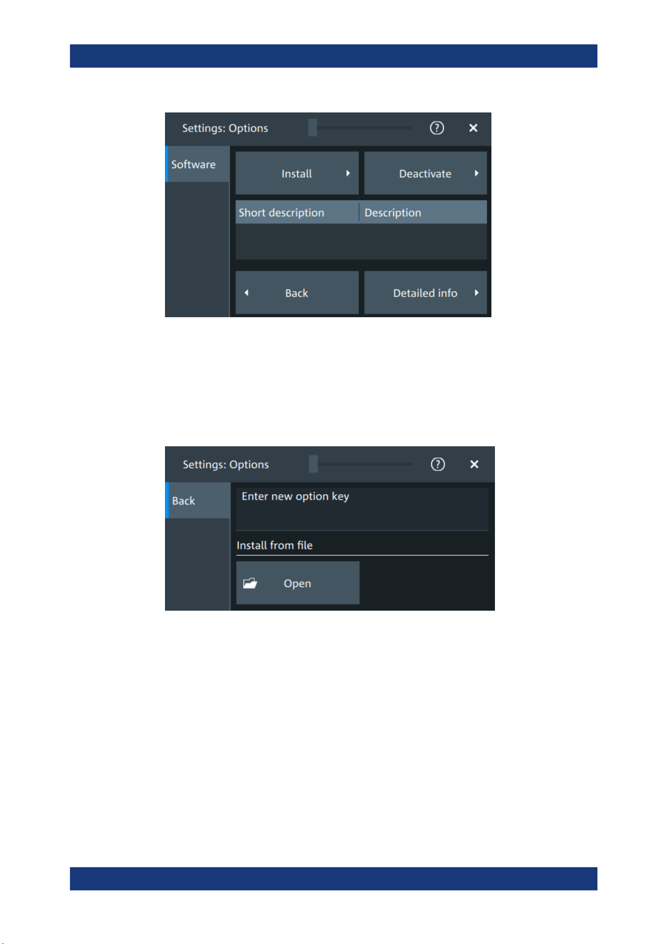
Instrument setup
R&S
®
MXO 5 Series
77User Manual 1802.3369.02 ─ 02
In this dialog, you can access settings for installing and deactivating options. In the
"Detailed Info" dialog, you can get an overview of all options installed on your
R&S MXO 5.
5.2.1.1 Install options
Access: "Settings" > "Options" > "Software" > "Install"
In the "Install" tab, you can install new options using license keys.
Enter new option key
Enter the license key here to activate the option. For license keys delivered as a file,
use "Install from file" on page 77.
Install from file
If you got a license file, install the license here.
Tap "Open" to open the file selection dialog, or enter the complete path and filename.
5.2.1.2 Deactivate options
Access: "Settings" > "Options" > "Software" > "Deactivate"
Option settings
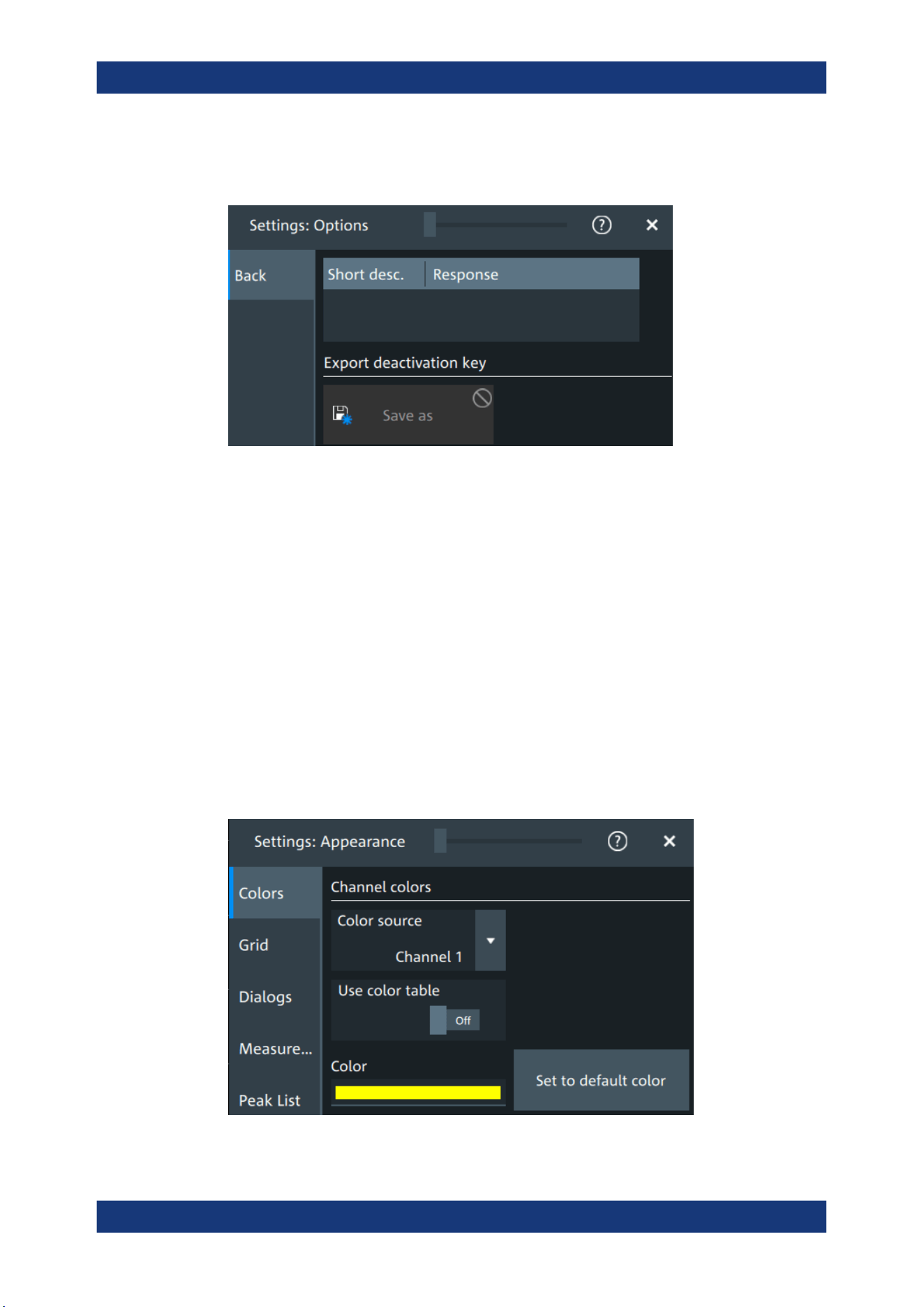
Instrument setup
R&S
®
MXO 5 Series
78User Manual 1802.3369.02 ─ 02
When you deactivate an option, you might need to note the response key, or to save
the response to a file. This is done in the "Deactivate" dialog.
5.3
Appearance settings
In the "Settings" > "Appearance" dialog box, you define the look and feel of the display
element, e.g. waveform colors, result position, or grid behavior.
Appearance settings are not included in user-defined presets. To reset all appearance
settings at once, user the factory preset.
5.3.1 Colors
Access: "Settings" > "Appearance" > "Colors"
By default, various colors are assigned to the different waveform types for better visibil-
ity and distinguishability. You can change the color assignment and select another
color or a color table to waveforms.
Appearance settings

Instrument setup
R&S
®
MXO 5 Series
79User Manual 1802.3369.02 ─ 02
Color source
Selects the waveform to which the color or the color table is assigned.
Use color table
If enabled, the selected waveform is displayed according to its assigned color table.
If disabled, the selected color is displayed, and the intensity of the signal color varies
according to the cumulative occurrence of the values.
Remote command:
DISPlay:COLor:SIGNal:USE on page 450
Assigned color table
Assigns a color table to the source waveform instead of a dedicated color. Color tables
define the color of the waveform pixels depending on the cumulative occurrence of the
associated values.
The following color tables are provided:
●
"False colors": color changes gradually in a wide color spectrum.
●
"Single Event": single events and very seldom events appear yellow, a higher
cumulative occurrence is shown with blue color. This view helps to identify specific
events.
●
"Spectrum": colors display the wavelengths of the light. Low cumulative occurrence
is displayed blue like high wavelength.
●
"Temperature": color changes gradually from blue (low temperature) to red (high
temperature) with increasing cumulative occurrence.
Remote command:
DISPlay:COLor:SIGNal:ASSign on page 450
Color
Shows the current color of the selected waveform. To change the color, tap the button
to open the "Color" dialog.
In the dialog, you can pick from a list of basic colors, or define a color with the color
picker.
Appearance settings
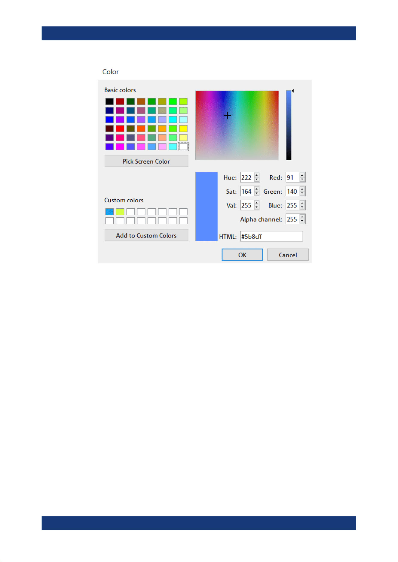
Instrument setup
R&S
®
MXO 5 Series
80User Manual 1802.3369.02 ─ 02
The color of the waveform, its signal icon, and of the illuminated keys is adjusted to the
new color. If the waveform is a spectrum, the knobs for vertical scale and position
retain the color of the spectrum's source.
Remote command:
DISPlay:COLor:SIGNal:COLor on page 450
Set to default color
Resets the color of the selected waveform to the factory default.
Remote command:
DISPlay:COLor:SIGNal:COLor <Signal>,DEF
5.3.2 Grid
Access: "Settings" > "Appearance" > "Grid"
Appearance settings
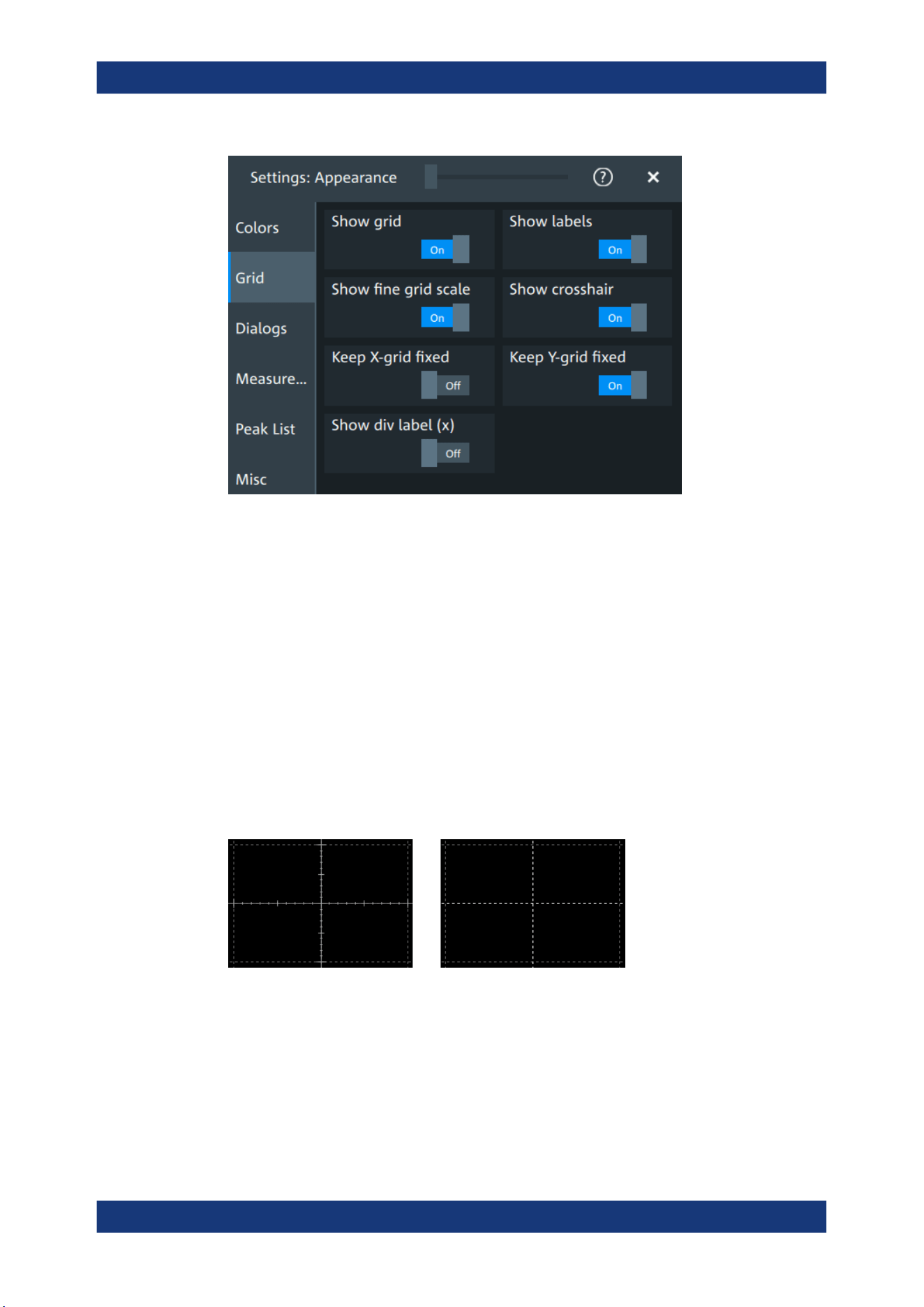
Instrument setup
R&S
®
MXO 5 Series
81User Manual 1802.3369.02 ─ 02
Show grid
If selected, a grid is displayed in the diagram area. A grid helps you associate a spe-
cific data point to its exact value on the x- or y-axis.
Remote command:
DISPlay:DIAGram:GRID on page 451
Show labels
If selected, labels mark values on the x- and y-axes in specified intervals in the dia-
gram.
Remote command:
DISPlay:DIAGram:LABels on page 451
Show fine grid scale
If selected, the crosshair is displayed as a ruler with scale markers. If disabled, the
crosshair is shown as dashed lines.
Remote command:
DISPlay:DIAGram:FINegrid on page 451
Show crosshair
If selected, a crosshair is displayed in the diagram area. A crosshair allows you to
select a specific data point by its coordinates.
Appearance settings
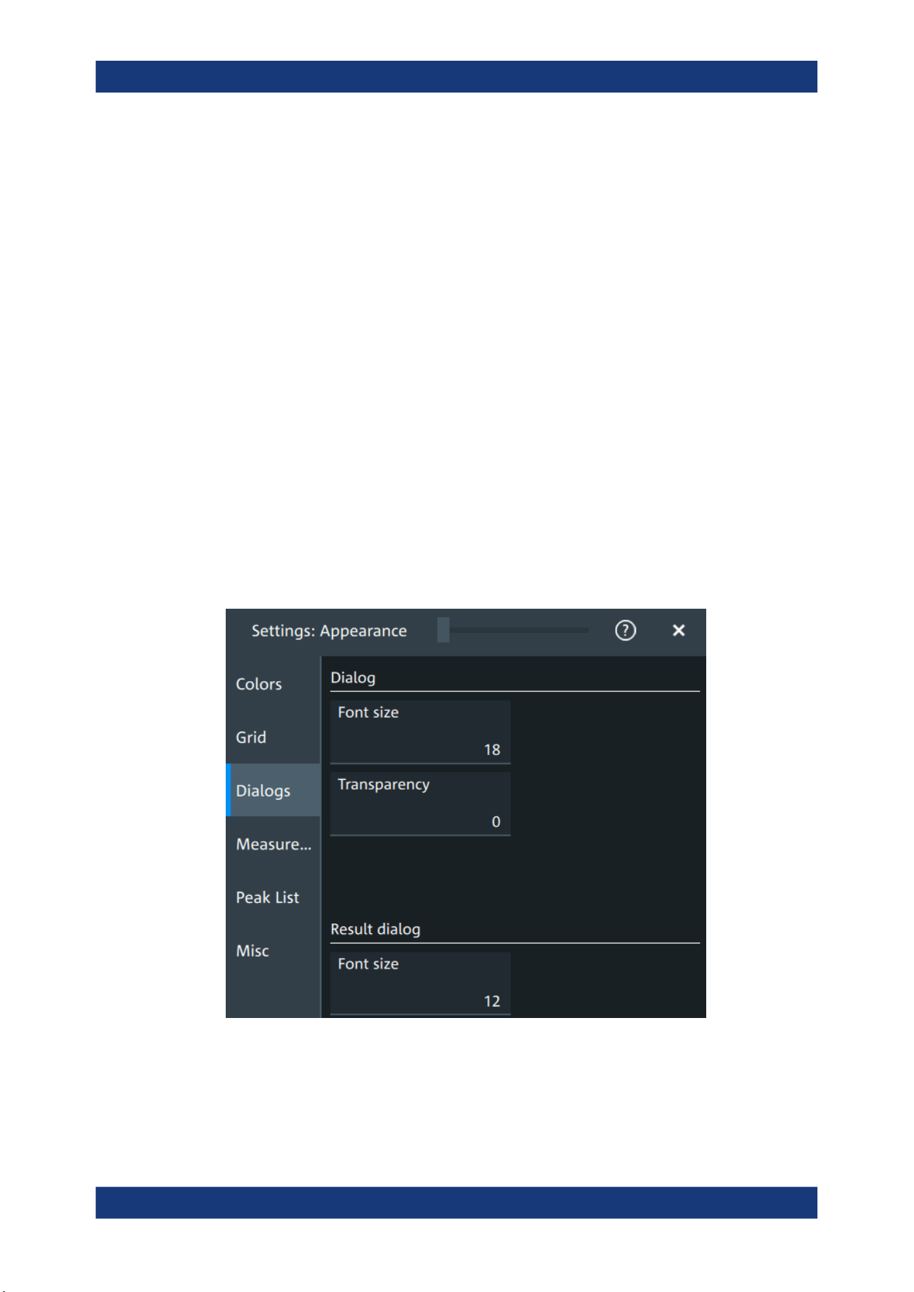
Instrument setup
R&S
®
MXO 5 Series
82User Manual 1802.3369.02 ─ 02
Remote command:
DISPlay:DIAGram:CROSshair on page 451
Keep X-grid fixed
If enabled, the vertical grid lines remain in their position when the horizontal position is
changed. Only the values at the grid lines are adapted.
Keep Y-grid fixed
If enabled, the horizontal grid lines remain in their position when the position of the
curve is changed. Only the values at the grid lines are adapted.
Fixed horizontal grid lines correspond to the behavior of traditional oscilloscopes.
Remote command:
DISPlay:DIAGram:YFIXed on page 452
Show div label (x)
If selected, the time scale value is shown at the diagram bottom instead of the horizon-
tal grid labels. For example, 10 ns/div is shown instead of the values 0, 10, 20, 30... ns.
5.3.3 Dialogs
Access: "Settings" > "Appearance" > "Dialogs"
Font size (Dialog)
Sets the font size of the text in dialog boxes.
Remote command:
DISPlay:DIALog:FONTsize on page 452
Appearance settings
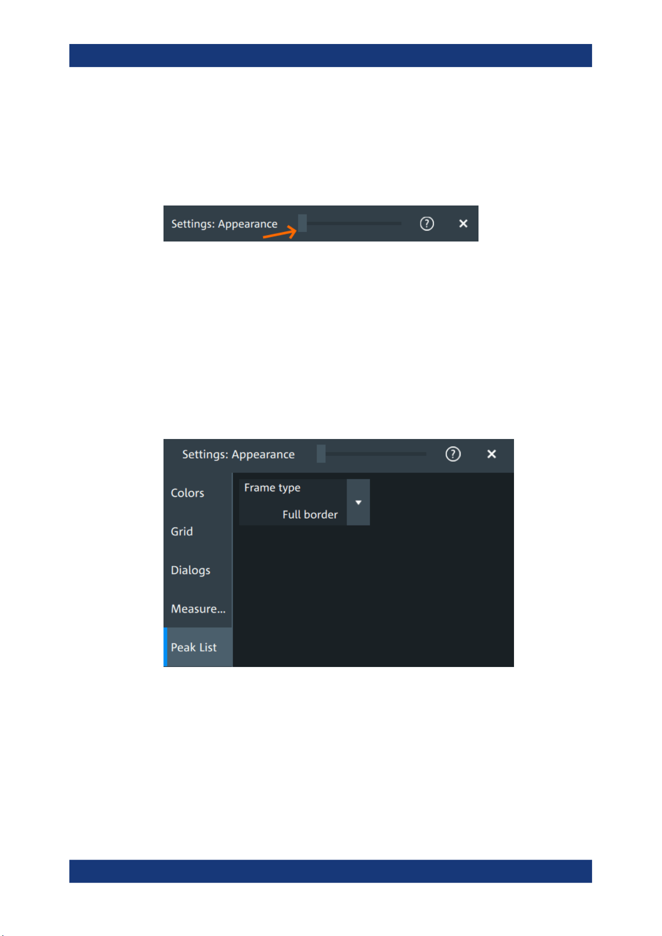
Instrument setup
R&S
®
MXO 5 Series
83User Manual 1802.3369.02 ─ 02
Transparency (Dialog)
Sets the transparency of the dialog box background. For high transparency values, you
can see the waveform display in the background, and possibly check the effect of the
changed setting. For lower transparency values, readability in the dialog box improves.
You can also set the dialog transparency, by moving the transparency bar at the top of
the dialog.
Remote command:
DISPlay:DIALog:TRANsparency on page 452
Font size (Result dialog)
Sets the font size of the text in result tables.
Remote command:
DISPlay:RESult:FONTsize on page 453
5.3.4 Peak list
Access: "Settings" > "Appearance" > "Peak list"
Peak list settings apply to peak list measurements. They are visible when the peak list
for spectrum measurements is enabled.
Frame type
Defines the layout of the labels, full border or none.
Remote command:
CALCulate:SPECtrum<sp>:PLISt:LABel:BORDer on page 453
Appearance settings
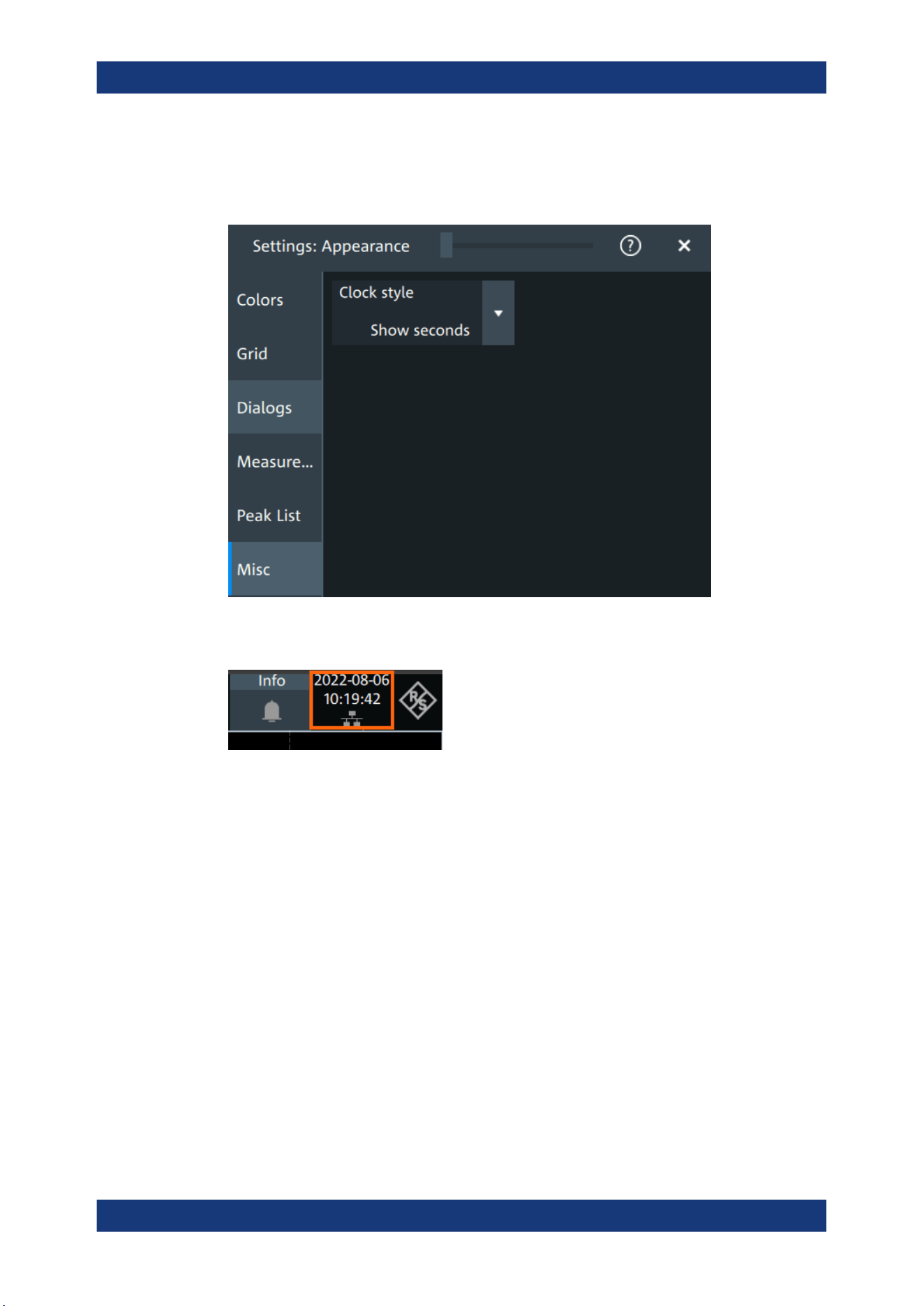
Instrument setup
R&S
®
MXO 5 Series
84User Manual 1802.3369.02 ─ 02
5.3.5 Miscellaneous
Access: "Settings" > "Appearance" > "Misc"
Clock style
Select how the clock in the upper right corner of the screen is displayed:
●
"Show seconds": format is hh:mm:ss
●
"Hide seconds": format is hh:mm
●
"Hide clock": no time is shown
5.4 Display settings
In the "Settings" > "Display" dialog, you can define the display settings like brightness
and signal intensity.
5.4.1 Persistence settings
Access: "Menu" > "Settings" > "Display" > "Persistence".
Display settings
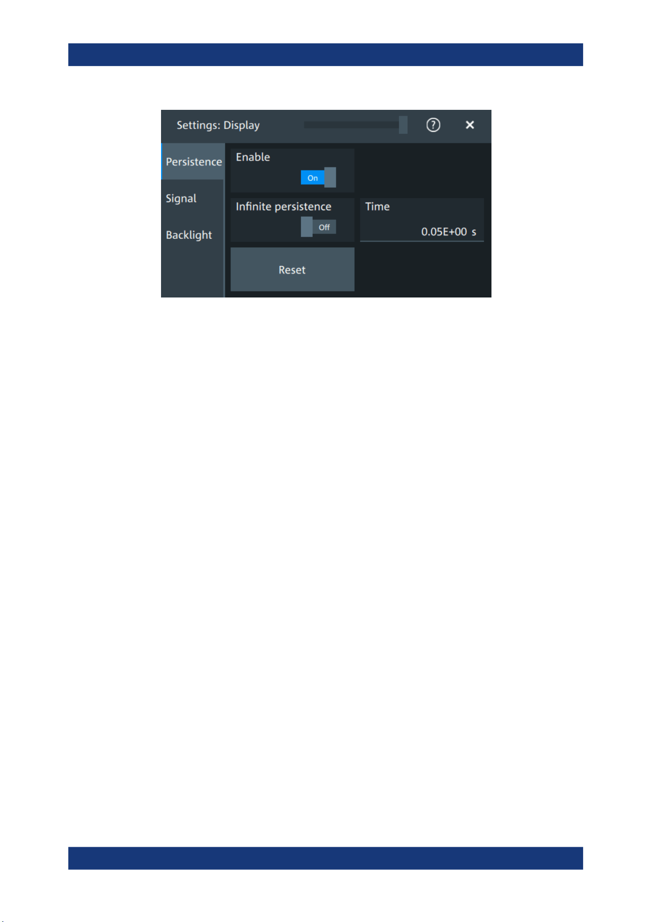
Instrument setup
R&S
®
MXO 5 Series
85User Manual 1802.3369.02 ─ 02
Enable
If enabled, each new data point in the diagram area remains on the screen for the
duration that is defined using Time, or as long as Infinite persistence is enabled.
If disabled, the waveform points are displayed only for the current acquisition.
Remote command:
DISPlay:PERSistence[:STATe] on page 454
Infinite persistence
If infinite persistence is enabled, each new waveform point remains on the screen until
this option is disabled. Use infinite persistence to display rare events in the signal.
Remote command:
DISPlay:PERSistence:INFinite on page 454
Time
Sets a time factor that controls how long the waveforms points fade away from the dis-
play. Thus, the R&S MXO 5 emulates the persistence of analog phosphor screens.
Remote command:
DISPlay:PERSistence:TIME on page 454
Reset
Resets the display, removing persistent all waveform points.
Remote command:
DISPlay:PERSistence:RESet on page 454
5.4.2 Signal settings
Access: "Menu" > "Settings" > "Display" > "Signal".
Display settings
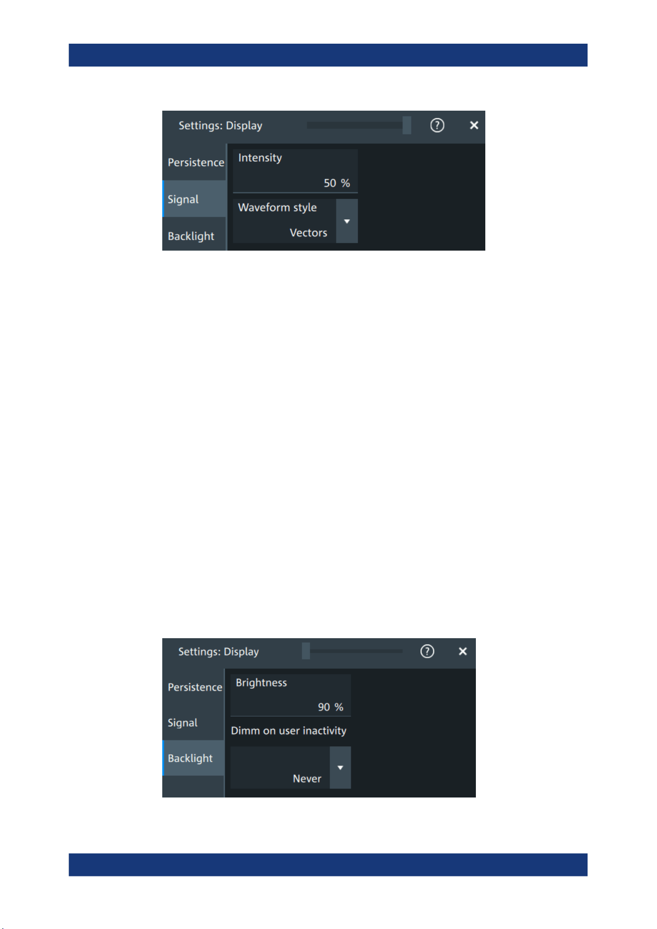
Instrument setup
R&S
®
MXO 5 Series
86User Manual 1802.3369.02 ─ 02
Intensity
The intensity determines the strength of the waveform line in the diagram. Enter a per-
centage between 0 (not visible) and 100% (strong). The default value is 50%.
You can also use the [Intensity] knob to adjust the waveform intensity directly.
Remote command:
DISPlay:INTensity on page 455
Waveform style
Selects the style in which the waveform is displayed.
"Vectors"
The individual waveform points are connected by a line.
Define the strength of the line using the [Intensity] knob.
"Dots"
Only the individual waveform points are displayed.
To see the dots of one waveform, perform one acquisition with
[Single] and N=1 (N-single/Avg count). During continuous acquisition,
or a [Single] acquisition with N > 1, the dots of multiple subsequent
waveforms are displayed on the screen, and the waveform looks like
a line.
Remote command:
DISPlay:DIAGram:STYLe on page 455
5.4.3 Backlight settings
Access: "Menu" > "Settings" > "Display" > "Backlight".
Display settings
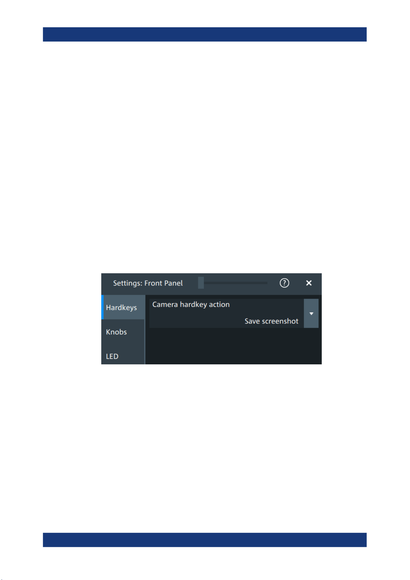
Instrument setup
R&S
®
MXO 5 Series
87User Manual 1802.3369.02 ─ 02
Brightness
Sets the background luminosity of the touchscreen.
Remote command:
DISPlay:BACKlight[:BRIGtness] on page 455
Dimm on user inactivity
Selects a time, after which the monitor brightness is reduced, if the instrument was
inactive. Remote control of the instrument is also considered as an activity.
Remote command:
DISPlay:BACKlight:DIMMing on page 456
5.5 Front panel settings
In the "Front Panel" dialog box, you can assign functions to keys and knobs and adjust
the brightness of the keys.
5.5.1 Hardkeys: function assignment
Access: "Settings" > "Front Panel" > "Hardkeys"
Camera hardkey action
The Camera key on the bottom right is a shortcut key that initiates an associated
action.
You can assign one of the following actions:
●
Save screenshot
●
Open screenshot setup
Configure the settings for the selected action.
●
Screenshots: "Save/Recall" key > "Save" tab > "Screenshot", see Chapter 12.4,
"Screenshots", on page 280.
5.5.2 Knobs
Access: "Settings" > "Front Panel" > "Knobs"
Front panel settings
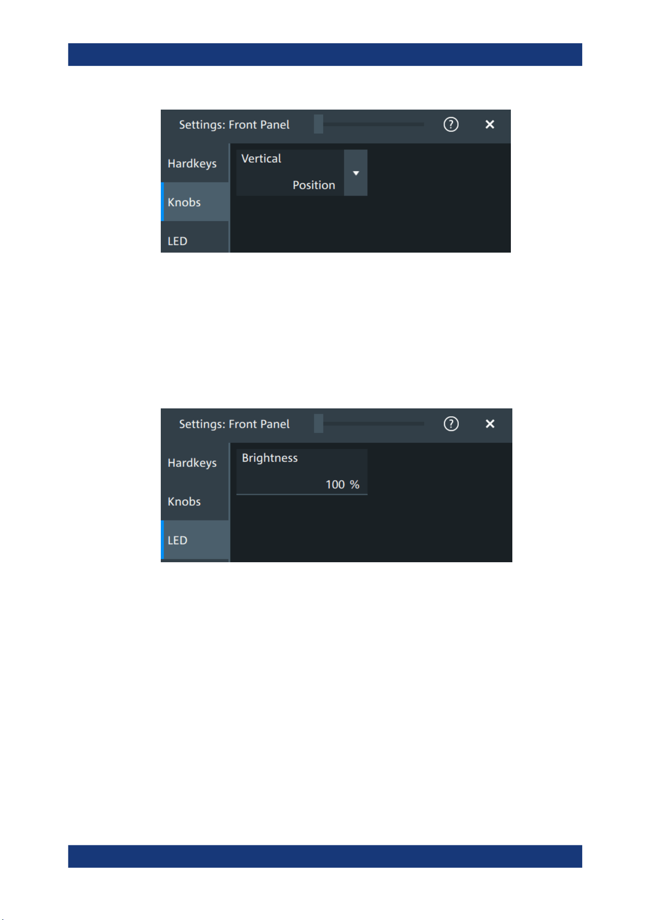
Instrument setup
R&S
®
MXO 5 Series
88User Manual 1802.3369.02 ─ 02
Vertical
The vertical Position knob can change the waveform position or the offset of the
selected waveform. Select the action that you want to perform.
See also: "[Position]" on page 39.
5.5.3 LED
Access: "Settings" > "Front Panel" > "LED".
Brightness
Defines the luminosity of illuminated front panel keys and knobs.
5.6 Preset setup
The preset sets the instrument to a default configuration, or to a user-defined configu-
ration. A user-defined preset file is one of the saveset files, which are stored on the
instrument. It contains the measurement setup, while the user's display settings are not
included. You can save the current configuration to a preset file, and enable saved pre-
set file to be applied with the [Preset] key.
See also: Chapter 12.1, "Save and recall user settings", on page 267.
Preset setup
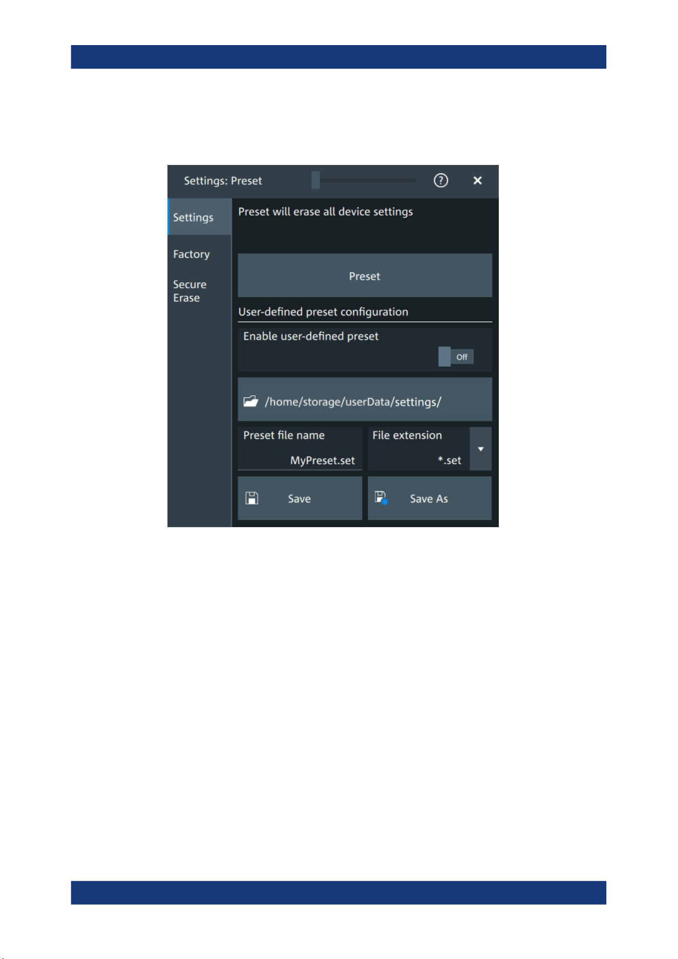
Instrument setup
R&S
®
MXO 5 Series
89User Manual 1802.3369.02 ─ 02
5.6.1 Preset settings
Access: "Menu" > "Settings" > "Preset" > "Settings".
Preset
Set the instrument to a default configuration, or to a user-defined configuration.
Enable user-defined preset
If enabled, the settings from the selected saveset are restored when the [Preset] key is
pressed.
If disabled, [Preset] sets the instrument to the factory defaults.
Saveset to be loaded on preset
Select the saveset file that contains the required settings. If "Enable user-defined pre-
set" is enabled, this saveset is loaded when you press the [Preset] key.
"Preset file
name"
Enter the filename of the preset file. This file is loaded on user-
defined preset. The filename is also used when you save a preset file
with "Preset file name".
"File exten-
sion"
The file extension is .set.
<Directory>
Shows the currently used directory. To change the directory, tap the
button and select the correct directory in the file dialog.
Preset setup
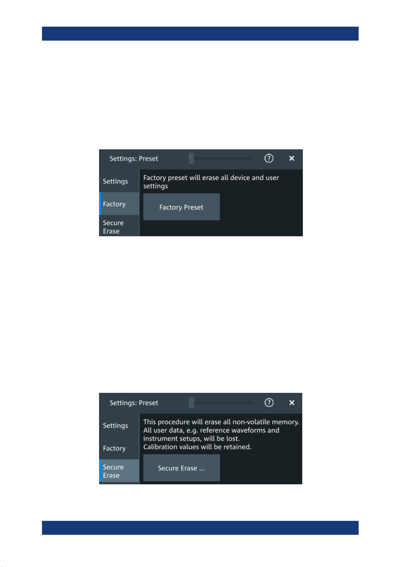
Instrument setup
R&S
®
MXO 5 Series
90User Manual 1802.3369.02 ─ 02
Save as, Save
"Save as" opens the file selection dialog, where you can select the directory and enter
the filename of the preset file. "Save" saves the current settings immediately to the file
that is named in "Preset file name" in the current directory.
5.6.2 Factory preset
Access: "Menu" > "Settings" > "Preset" > "Factory".
Factory preset
Resets the instrument to the factory default settings, to the initial state. Factory settings
comprise all instrument settings, including display, intensity and transparency settings.
Remote command:
SYSTem:PRESet on page 442
5.6.3 Secure erase
Access: "Menu" > "Settings" > "Preset" > "Secure erase"
To purge all non-volatile memory, a special delete function is available. This function
erases all user data, including instrument setups and reference waveforms. Calibration
data is retained on the instrument. The instrument reboots after erasing the data.
The procedure is required if user data must not leave the test area with the instrument,
e.g. when working in highly secured environments.
Preset setup

Instrument setup
R&S
®
MXO 5 Series
91User Manual 1802.3369.02 ─ 02
5.6.4 Restoring settings
When you have changed many settings on the instrument, and you are not sure which
settings are causing which effect, you can restore the default settings and start anew.
The following methods are available:
●
Saving instrument settings as a user-defined preset and restoring the instrument
settings to user-defined default values
●
Restoring all settings on the R&S MXO 5 to the factory-defined values
●
Restoring settings from a file
To save a user-defined preset
1. Open the "Menu" > "Settings" > "Preset" tab.
2. Enter a name for the preset file. Select the file format.
3. Tap "Save preset file".
Note: If you want to store the file in another directory than the displayed one,
select "Save as". See also: Chapter 12.5, "File browser dialog", on page 283.
To restore the instrument settings to user-defined default values
1. Open the "Menu" > "Settings" > "Preset" > "Settings" tab.
2. In "Preset file name", enter the name of the file that contains the required settings.
3. To use these settings as preset values, select "Enable user-defined preset".
4. Press the [Preset] key.
To restore all settings to the factory defaults
1. Open the "Menu" > "Settings" > "Preset" > "Factory" tab.
2. Tap the "Factory preset" button.
All settings on the R&S MXO 5 are reset to their factory-defined values.
As long as no user-defined preset file is loaded and "Enable user-defined preset" is
disabled, the [Preset] key also resets the instrument settings to factory defaults.
5.7 Maintenance settings
In the "Settings" > "Maintenance" dialog box, you can update the firmware, perform
self-alignment.
5.7.1 Firmware update
Access: "Menu" > "Settings" >"Maintenance" > "FW update".
Maintenance settings
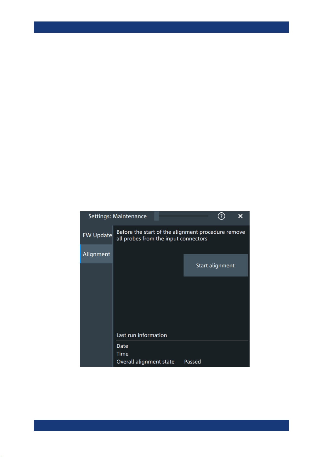
Instrument setup
R&S
®
MXO 5 Series
92User Manual 1802.3369.02 ─ 02
Your instrument is delivered with the latest firmware version. Firmware updates are
provided on the internet at:
The "Release Notes" describe the improvements and modifications of all firmware ver-
sions. They also explain how to update the firmware. They are available along with the
firmware on the same web page.
Remote commands:
●
SYSTem:FW:FILepath on page 442
●
SYSTem:FW:STARt on page 443
5.7.2 Alignment
When data from several input channels is displayed at the same time, it can be neces-
sary to align the data. Alignment is done vertically or horizontally to synchronize the
time bases or amplitudes and positions. Perform an alignment, for example, when
strong temperature changes occur (> 5°).
5.7.2.1 Alignment settings
Access: "Menu" > "Settings" > "Maintenance" > "Alignment"
Start alignment
Starts the self-alignment procedure for all channels.
Maintenance settings
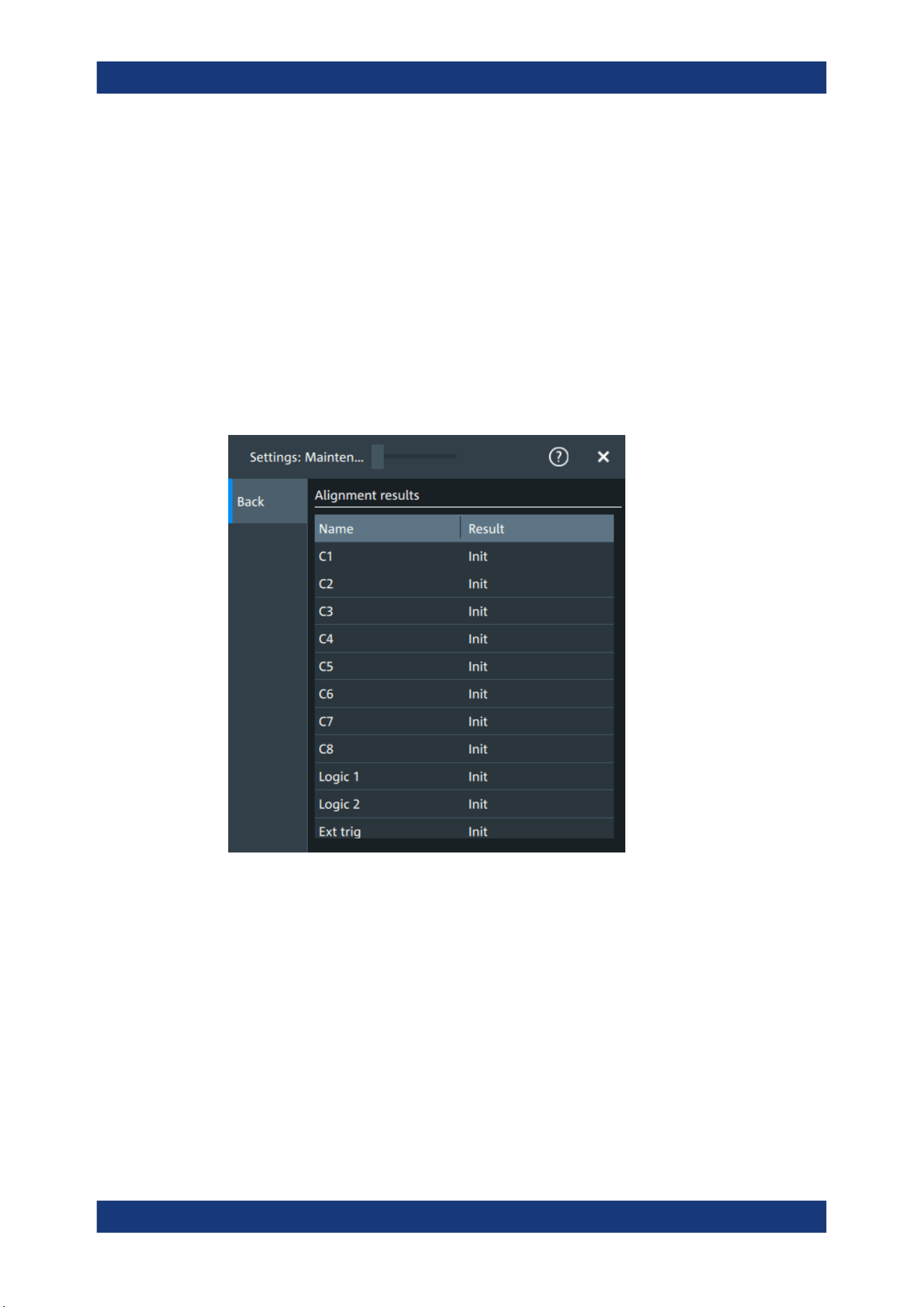
Instrument setup
R&S
®
MXO 5 Series
93User Manual 1802.3369.02 ─ 02
Date, Time, Overall alignment state
Show the date, time and the summary result of the self-alignment process: not aligned,
passed or failed. Detailed results are provided on the "Alignment results" tab.
Remote command:
CALibration:DATE? on page 459
CALibration:TIME? on page 459
CALibration:RESult? on page 459
Show results
Opens a dialog to display the alignment results.
For each channel, the results of the individual alignment steps are shown for all techni-
cal channel component. In case you require support, you may be asked to provide this
information.
5.7.2.2 Performing a self-alignment
The self-alignment aligns the data from several input channels vertically and horizon-
tally to synchronize the timebases, amplitudes and positions. The self-alignment proc-
ess includes a basic hardware check.
Recommendation on performing the self-alignment:
●
When putting the instrument into operation for the first time
●
After a firmware update
●
Once a week
●
When major temperature changes occur (> 5°)
Maintenance settings
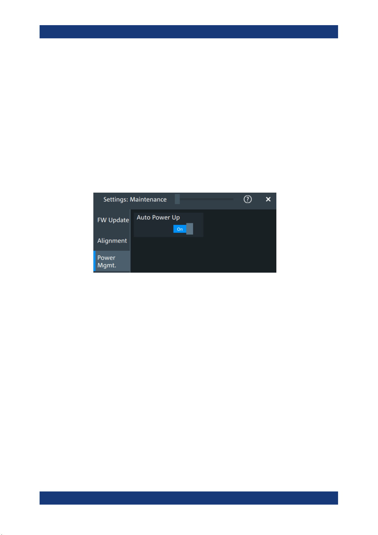
Instrument setup
R&S
®
MXO 5 Series
94User Manual 1802.3369.02 ─ 02
1. Warm up the instrument before you start the self-alignment. The minimum warm-up
time is indicated in the data sheet.
2. Remove the probes from the input connectors.
3. Open "Menu" > "Settings" > "Maintenance".
4. In the "Alignment" tab, tap "Start alignment".
The alignment is performed, the process can take several minutes. A message box
informs you about the running process, wait until this message box closes.
The overall pass/fail result is shown in the "Overall alignment state" field.
5.7.3 Power management
Access: "Menu" > "Settings" > "Maintenance" > "Power mgmt."
Auto power up
If enabled, the instrument powers up automatically when it is connected to the mains
voltage.
Remote command:
SYSTem:APUP on page 460
5.7.4 Service
Access: "Menu" > "Settings" > "Maintenance" > "Service"
Maintenance settings

Instrument setup
R&S
®
MXO 5 Series
95User Manual 1802.3369.02 ─ 02
Create report
Creates a service report.
The service report is a ZIP file with a complete bug report, all relevant setup informa-
tion, reporting and log files, alignment files, and the instrument configuration.
If a USB flash drive is connected, the report is saved on the USB flash drive. Other-
wise, the report is saved in the user data folder /home/storage/userData.
See also: Chapter 18.4, "Information for technical support", on page 792.
Remote command:
SERVice:REPort on page 459
5.8 Save / recall
5.8.1 Autonaming
Access:"Menu" > "Settings" key > "Save/Recall" > "Autonaming" tab.
Save / recall
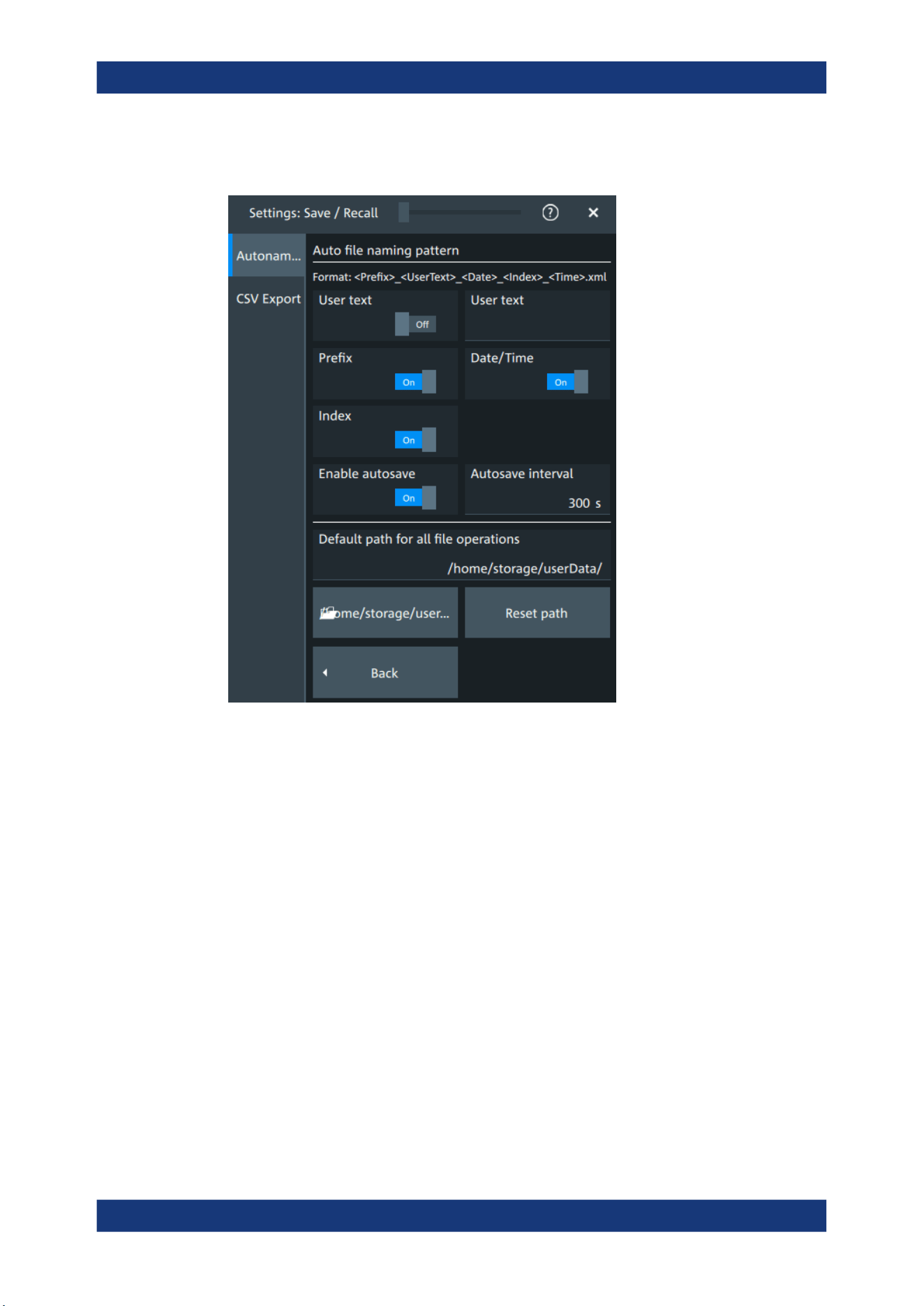
Instrument setup
R&S
®
MXO 5 Series
96User Manual 1802.3369.02 ─ 02
5.8.1.1 Autonaming settings
In the "Autonaming" tab, you can define the pattern for automatic file name generation.
This name is used as the default file name. The default path is the storage location for
all saved files and their subdirectories. The directory for user data on the instrument
is /home/storage/userData, the path to a USB storage device
is /run/media/usb/.
User text
If enabled, inserts the specified user text after the prefix.
Remote command:
MMEMory:AUTonaming:USERtext on page 457
MMEMory:AUTonaming:TEXT on page 458
Prefix
If enabled, inserts the default prefix in the file name. The prefix indicates the type of
data that is saved, for example, RefCurve, Settings.
Remote command:
MMEMory:AUTonaming:PREFix on page 456
Date/time
If enabled, the current date and time are inserted in the filename pattern.
Save / recall

Instrument setup
R&S
®
MXO 5 Series
97User Manual 1802.3369.02 ─ 02
Remote command:
MMEMory:AUTonaming:TIME on page 456
Index
If enabled, inserts an index.
Remote command:
MMEMory:AUTonaming:INDex on page 456
Enable autosave
Enables the automatic saving of the waveform. With "Autosave interval", you can
define the time interval for the automatic saving.
Remote command:
MMEMory:AUSave:ENABle on page 457
MMEMory:AUSave:INTerval on page 457
Default path for all file operations
Defines the path that is displayed in the file selection dialog box for loading and storing
operations. On the instrument, all user data is written to /home/storage/userData.
You can create subfolders in this folder. The path to a USB storage device
is /run/media/usb/.
To switch the directory quickly, double-tap the path button. Use the symbols on the left
of the file explorer box to change the directory.
Remote command:
MMEMory:AUTonaming:DEFaultpath on page 458
Reset path
Resets the default file path to the factory default.
Remote command:
MMEMory:AUTonaming:RESPath on page 458
MMEMory:AUTonaming:RESall on page 458
5.8.1.2 Defining default file paths and names
When a save or load operation is performed, a default file name and path is provided.
You can configure which path is used and how the file name is generated. In the file
selection dialog box, you can change the folder and name as desired.
To define the default file path
1. Tap "Menu" > "Settings".
2. Select the "Save/Recall" tab.
3. Select the "Autonaming" tab.
4. Double-tap the path button.
The directory selection dialog box is opened.
Save / recall
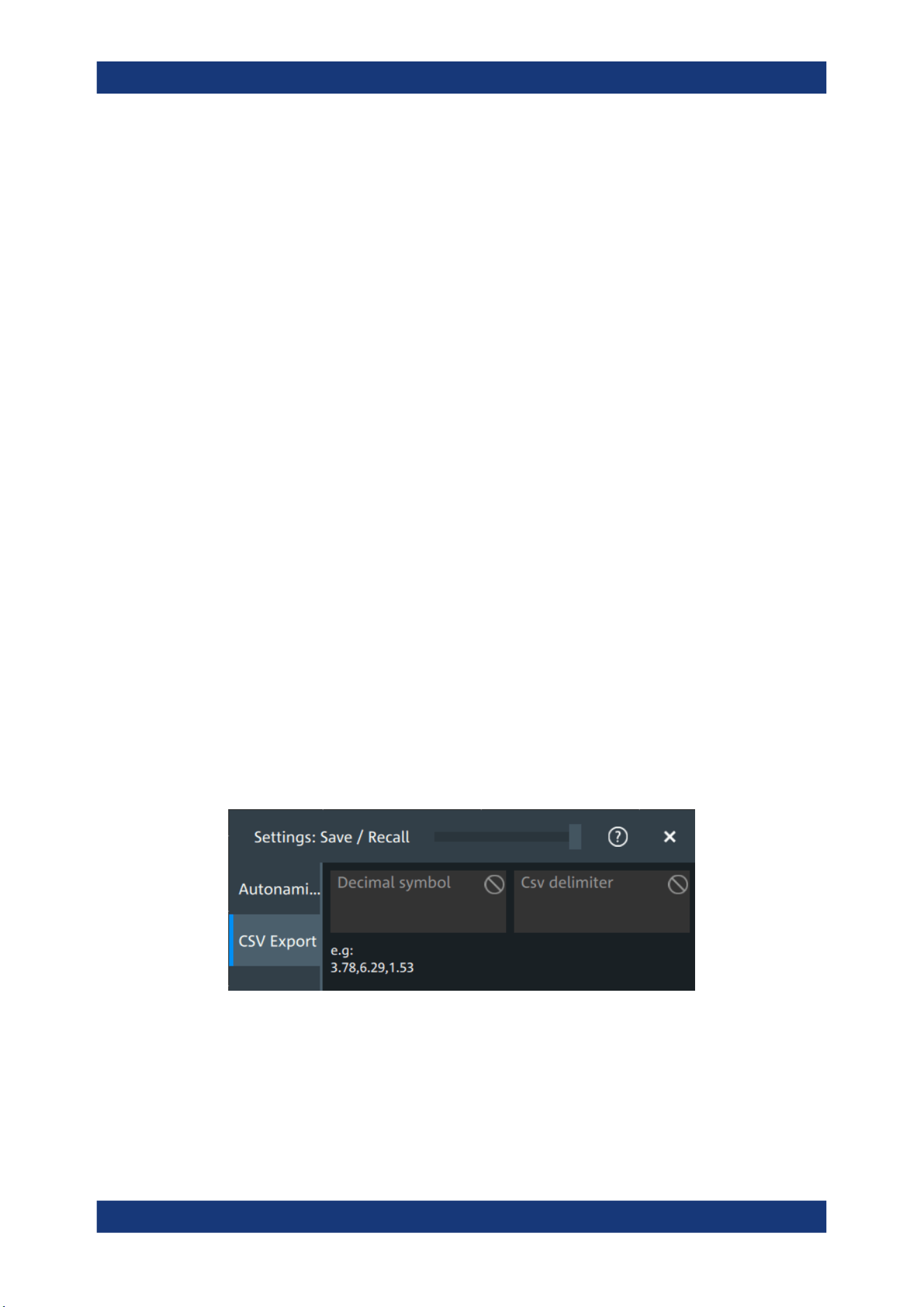
Instrument setup
R&S
®
MXO 5 Series
98User Manual 1802.3369.02 ─ 02
5. Select the folder in which the data is stored by default. Use the symbols on the left
of the file explorer box to switch to often used directories.
Alternatively, you can tap the "Default path for all file operations" field and type the
path.
6. To restore the factory-set default path, tap "Reset" next to the path field.
To define the automatic file name pattern
The automatic file name pattern can consist of the following elements:
<Prefix>_<UserText>_<Date>_<Index>_<Time>
The prefix depends on the data type to be stored and cannot be changed by the user.
The other elements can be enabled or disabled as required.
1. Tap "Menu" > "Settings".
2. Select the "Save/Recall" tab.
3. Select the "Autonaming" tab.
4. If you want to exclude the "Prefix", "Date/time" or an "Index" (serial number), dis-
able the corresponding option.
5. To insert a user-defined text after the prefix, enable "User text". Enter the text in the
edit field.
The specified elements are used to generate the default file name for the next stor-
age operation.
5.8.2 CSV export
Access:"Menu" > "Settings" key > "Save/Recall" > "CSV export" tab.
In this dialog, you can define the format of your CSV file.
Decimal symbol
Selects if point or comma is used as a decimal symbol in the exported CSV file.
CSV delimiter
Selects the list separator symbol from a list. Available are semicolon, comma, space,
tab and colon.
Save / recall

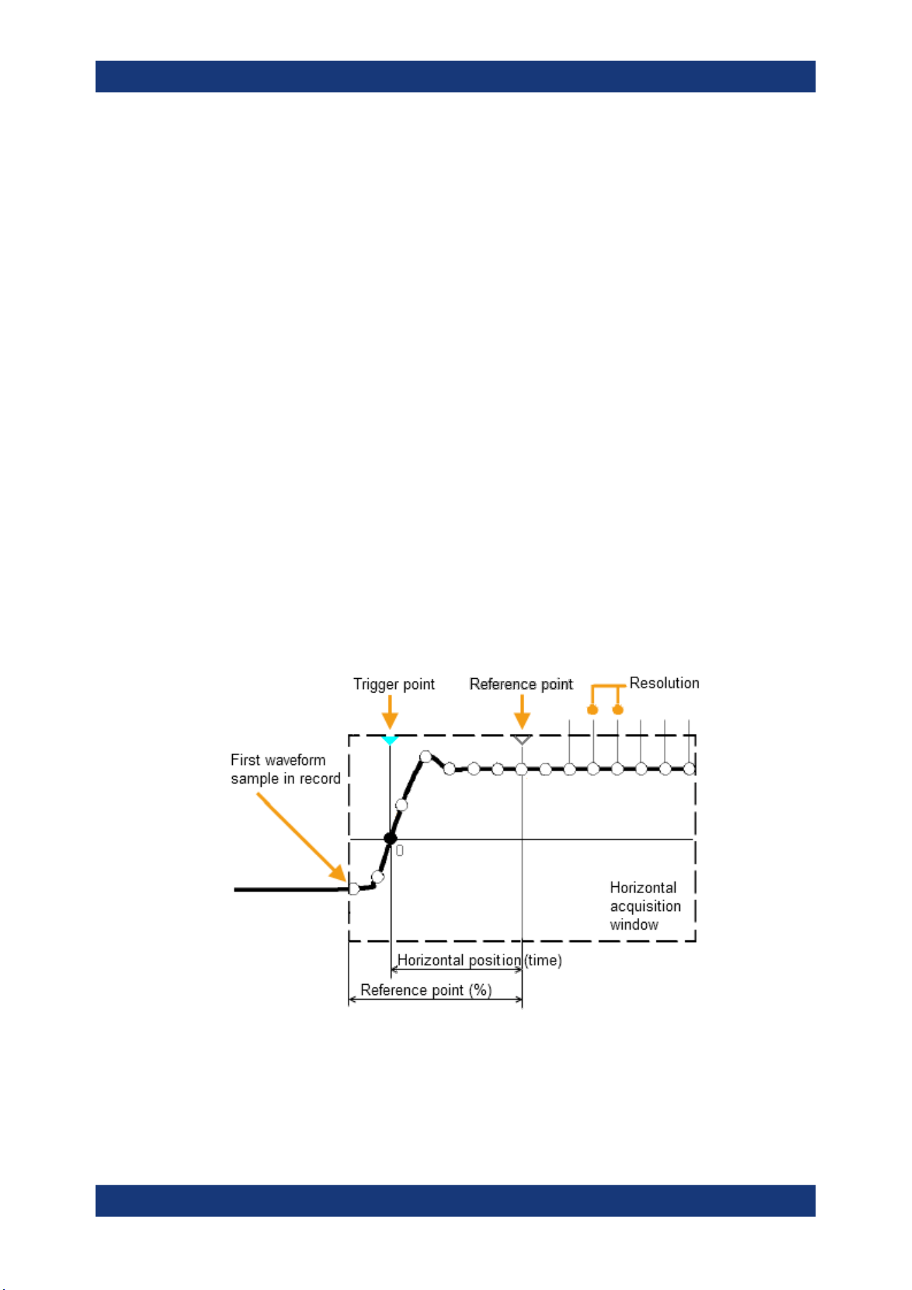
Acquisition and waveform setup
R&S
®
MXO 5 Series
100User Manual 1802.3369.02 ─ 02
6 Acquisition and waveform setup
6.1 Horizontal setup
The "Horizontal" dialog provides the time base configuration for channel and spectrum
waveforms.
6.1.1 About the horizontal system
Horizontal settings, also known as timebase settings, adjust the waveforms in horizon-
tal direction.
Typically, the trigger is the determining point of the waveform record. In many scenar-
ios, you want to analyze the waveform some time before or after the trigger. To adjust
the horizontal acquisition window to the waveform section of interest, you can use the
following parameters:
●
The horizontal position defines the time distance of the trigger point (the zero
point of the diagram) to the reference point. Changing the horizontal position, you
can move the trigger point, even outside the screen.
●
The reference point is the rescaling center of the time scale on the screen. If you
modify the time scale, the reference point remains fixed on the screen, and the
scale is stretched or compressed to both sides of the reference point.
Unlike vertical settings, which are waveform-specific, the horizontal settings apply to all
active waveforms.
Timebase settings are interdependent:
Timebase range = Time scale * Number of divisions
Horizontal setup
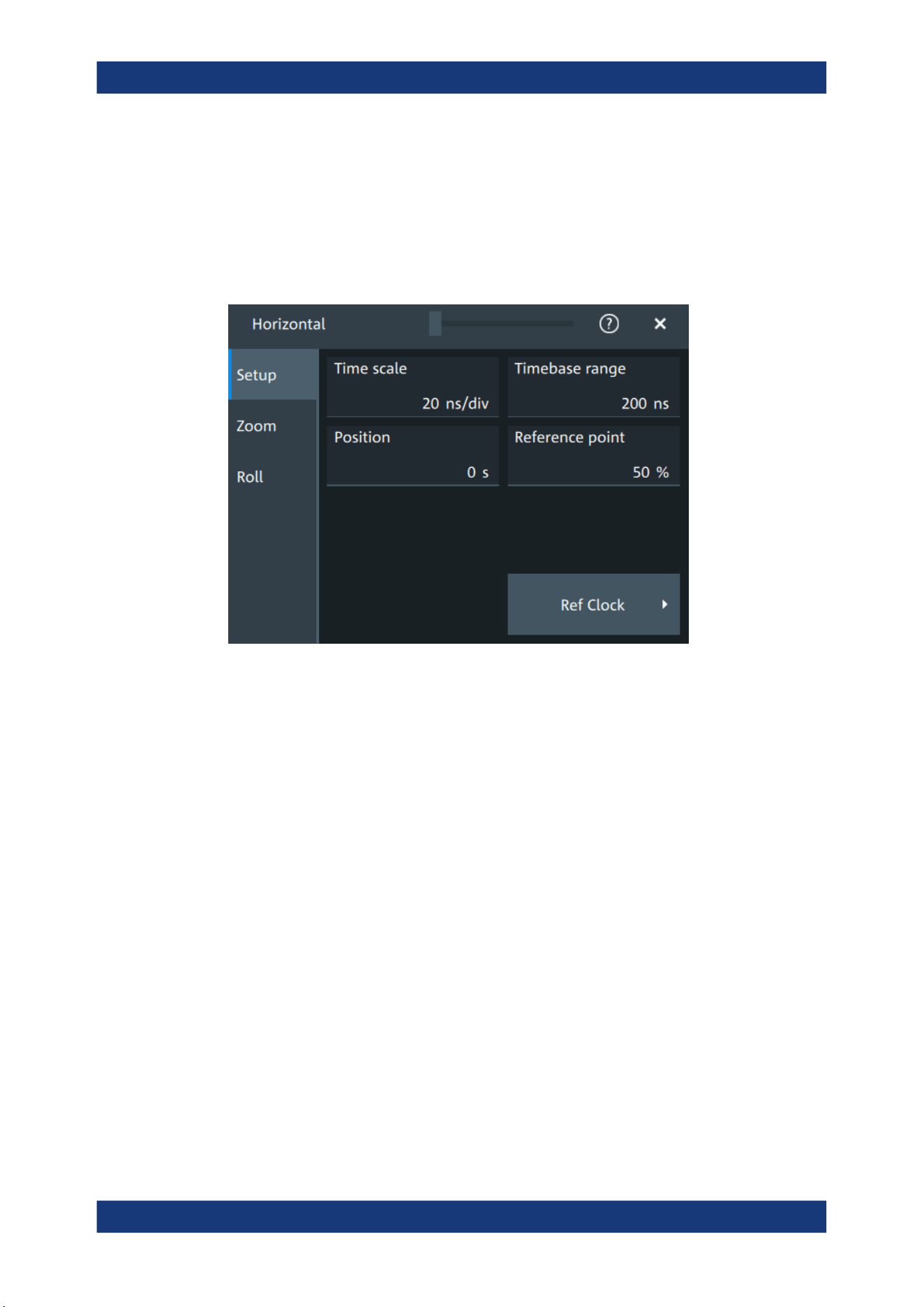
Acquisition and waveform setup
R&S
®
MXO 5 Series
101User Manual 1802.3369.02 ─ 02
The number of divisions is 10, which is the only constant parameter.
6.1.2 Horizontal Setup settings
Access: "Menu" > "Horizontal" > "Setup" tab, or tap the "Horizontal" label above the
diagram.
Time scale
Sets the horizontal scale, the time per division, for all waveforms in the time domain,
for example, channel and math waveforms.
Increase the scale to see a longer time interval of the waveform. Decrease the scale to
see it in more detail. The scale has a point that remains fixed on the screen when the
scale value is changing: the reference point.
Remote command:
TIMebase:SCALe on page 461
Timebase range
Sets the time of one acquisition, which is the time across the 10 divisions of the dia-
gram: Acquisition time = Time scale * 10 divisions.
Changing the acquisition time changes the time scale, too.
For long timebases, the acquisition progress is shown in the acquisition label, see
"Progress information" on page 66.
Remote command:
TIMebase:RANGe on page 461
Position
Defines the time distance between the reference point and the trigger point, which is
the zero point of the diagram. The horizontal position is also known as trigger offset.
Horizontal setup
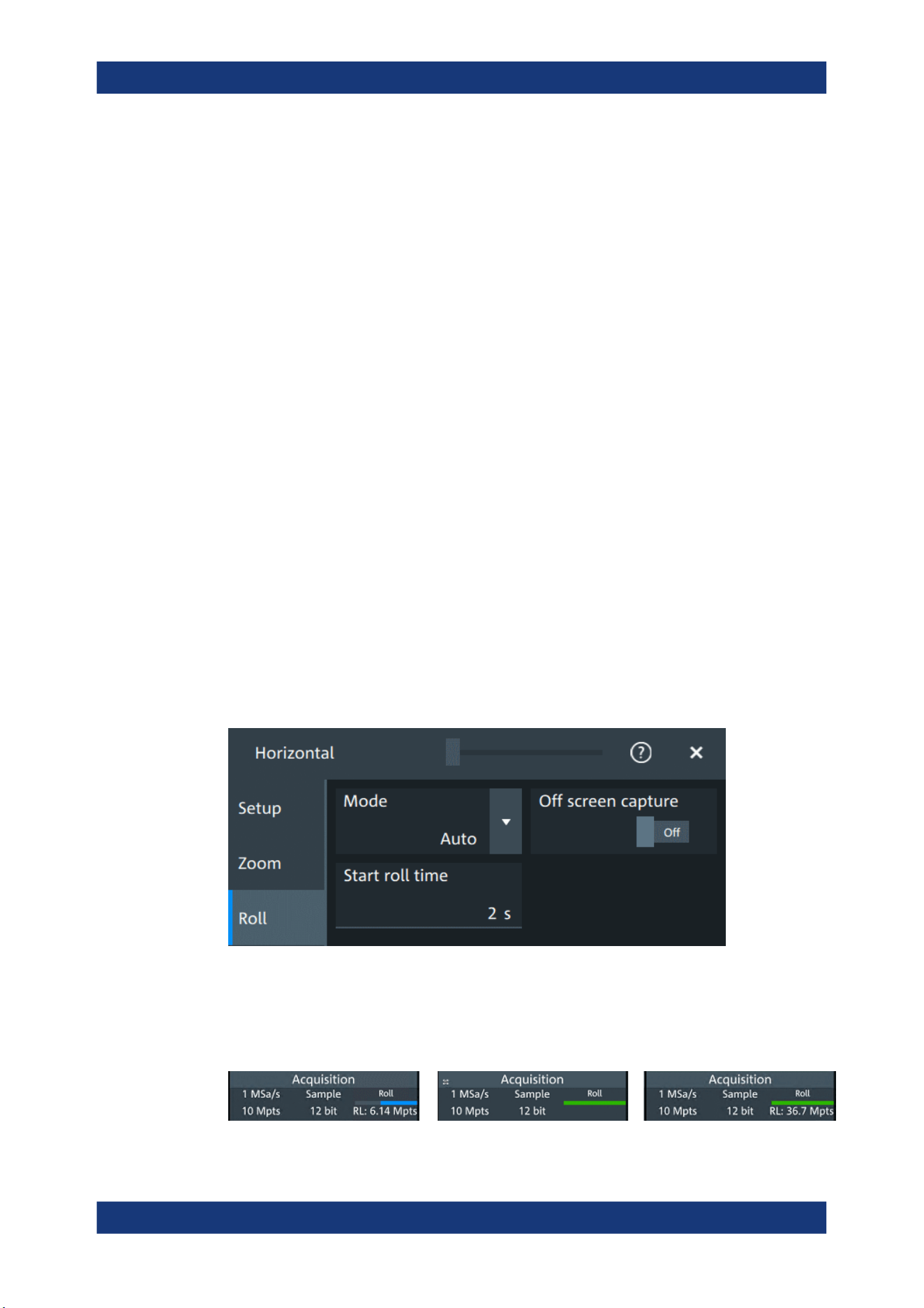
Acquisition and waveform setup
R&S
®
MXO 5 Series
102User Manual 1802.3369.02 ─ 02
If you want to see a section of the waveform some time before or after the trigger, enter
this time as horizontal position. The requested waveform section is shown around the
reference point. Use positive values to see waveform sections after the trigger - the
waveform and the diagram origin move to the left.
Remote command:
TIMebase:HORizontal:POSition on page 462
Reference point
Sets the position of the reference point in % of the screen. It defines which part of the
waveform is shown.
The reference point marks the rescaling center of the time scale on the screen. If you
modify the time scale, the reference point remains fixed on the screen, and the scale is
stretched or compressed to both sides of the reference point. If the "Position" is 0, the
trigger point is on the reference point.
The reference point is not marked in the diagram.
Remote command:
TIMebase:REFerence on page 462
6.1.3 Zoom settings
The zoom settings are described in Chapter 8.1, "Zoom", on page 160.
6.1.4 Roll mode
Access: "Menu" > "Horizontal" > "Roll" tab.
In this dialog, you can define the behavior of the roll mode.
Progress bar
The "Roll" progress bar in the "Acquisition" label shows how the record length is filled.
The bar turns green when all samples are acquired, and the record is filled.
Horizontal setup

Acquisition and waveform setup
R&S
®
MXO 5 Series
103User Manual 1802.3369.02 ─ 02
Left = incomplete roll waveform
Middle = roll completed with "Off screen capture" = Off
Right = roll completed with "Off screen capture" = On
Mode
Selects, if the roll mode is set automatically by the instrument or if it is turned off.
In roll mode, the instrument shows the waveforms immediately, without waiting for the
complete acquisition of the waveform record. If the time base is slow - at long time
scale values - the roll mode saves waiting for the waveform display. The instrument
displays newly acquired waveform points at the right edge of the display and moves
the waveform to the left.
The roll mode has following restrictions:
●
Roll mode disables persistence
●
Event actions are not possible
The instrument activates the roll mode automatically if the following conditions are ful-
filled:
●
"Timebase range" exceeds the defined "Start roll time"
●
The "Acquisition mode" is set to "Sample" or "Peak detect"
●
"N-single/Avg count" = 1
●
Fast segmentation is disabled
●
Event actions are disabled
●
All serial buses are disabled
Measurement statistics evaluate the currently displayed waveform. Therefore, "Mea-
sure all events" is enabled automatically in roll mode.
Remote command:
TIMebase:ROLL:ENABle on page 463
TIMebase:ROLL:STATe? on page 464
Start roll time
Sets the minimum acquisition time for automatic start of the roll mode.
The instrument activates the roll mode automatically if the "Timebase range" exceeds
the value of the "Start roll time".
Remote command:
TIMebase:ROLL:MTIMe on page 463
Off screen capture
If enabled, the analyzable waveform in roll mode is extended. Samples that arrive the
left edge of the display are kept, they are moved to the unvisible area on the left.
After stopping the acquisition, you can analyze the complete roll waveform, including
the invisible part:
●
Increase the "Time scale" to see a longer part of the waveform.
●
Scroll the waveform: tap and drag the waveform to the right.
Horizontal setup

Acquisition and waveform setup
R&S
®
MXO 5 Series
104User Manual 1802.3369.02 ─ 02
The "Roll" progress bar in the "Acquisition" label shows how the record length is filled,
see "Progress bar" on page 102. If "Off screen capture" = Off, the analyzable record
length is the value that is set in the "Acquisition" > "Setup" tab. If "Off screen capture" =
On, the analyzable record length is longer. The value is shown in the progress bar
when the bar is green, or returned by the remote command ACQuire:ROLLmode:
POINts?.
Remote command:
ACQuire:ROLLmode:OSCapture on page 463
ACQuire:ROLLmode:POINts? on page 464
6.1.5 Reference clock
Access: "Menu" > "Horizontal" > "Setup" tab > "Ref Clock"
The oven-controlled crystal oscillator (OCXO) produces a 10 MHz internal reference
signal with precise and stable frequency. You can output this clock signal for synchroni-
zation of other instruments. Conversely, you can also use an external 10 MHz refer-
ence signal. The input and output connectors for reference signals are on the rear
panel of the instrument.
Use external ref. clock
Enables the use of an external 10 MHz reference signal instead of the internal refer-
ence clock.
Remote command:
SENSe[:ROSCillator]:SOURce on page 492
Output 10 MHz ref. signal
Sends the internal reference clock signal to the Ref Out 10 MHz connector.
If "Use external ref. clock" is enabled, the external reference signal is output instead of
the internal clock.
Remote command:
SENSe[:ROSCillator]:OUTPut[:ENABle] on page 491
6.2 Acquisition
Access: "Menu" > "Acquisition".
Acquisition settings define the processing of the captured samples in the instrument.
Acquisition
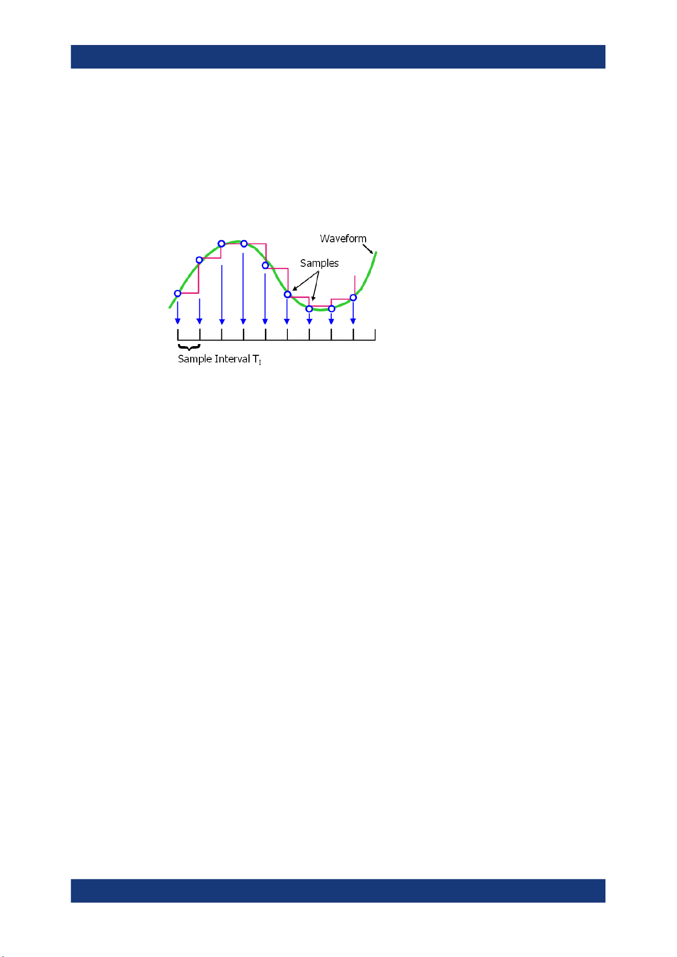
Acquisition and waveform setup
R&S
®
MXO 5 Series
105User Manual 1802.3369.02 ─ 02
6.2.1 About the acquisition system
Sampling and processing
The A/D converter samples the continuous signal under test at specific points in time
and captures digital values. The converter is working at a constant rate specified in
GHz.
The captured values are processed according to the acquisition settings. The result is
a waveform record that contains waveform samples and is stored in the waveform
memory. The waveform samples are displayed on the screen and build up the wave-
form.
The number of waveform samples in one waveform record is called record length.
The rate of recording waveform samples - the number of waveform samples per sec-
ond - is the sample rate. The higher the sample rate, the better the resolution is and
the more details of the waveform are visible.
Sample rate = 1 / Resolution
The sample rate can be the same as the constant rate of the A/D converter, or higher,
or lower. To get a higher sample rate, interpolation is used. Several interpolation meth-
ods are available. Other processing methods reduce the sample rate, or build the
resulting waveform from several consecutive acquisitions of the signal. These methods
are called acquisition modes.
Minimum sample rate and aliasing
A sufficient resolution is essential for correct reconstruction of the waveform. If the sig-
nal is undersampled, aliasing occurs - a false waveform is displayed. To avoid aliasing
and accurately reconstruct a signal, the sample rate must be at least 3 to 5 times the
fastest frequency component of the signal. A higher sample rate increases signal fidel-
ity, increases the chance to capture glitches and other signal anomalies, and improves
the zoom-in capabilities.
Interleaving
The R&S MXO 5 with 8 channels achieves its highest sample rate of 5 Gsample/s by
interleaving channels by twos. Interleaving assumes that only one of the paired chan-
nels is used. If the second channel of a pair is used (on display, or as trigger source,
math source, or measurement source), the interleaving mode is disabled. Without
interleaving, the channels work with 2.5 Gsample/s and reduced bandwidth.
Acquisition
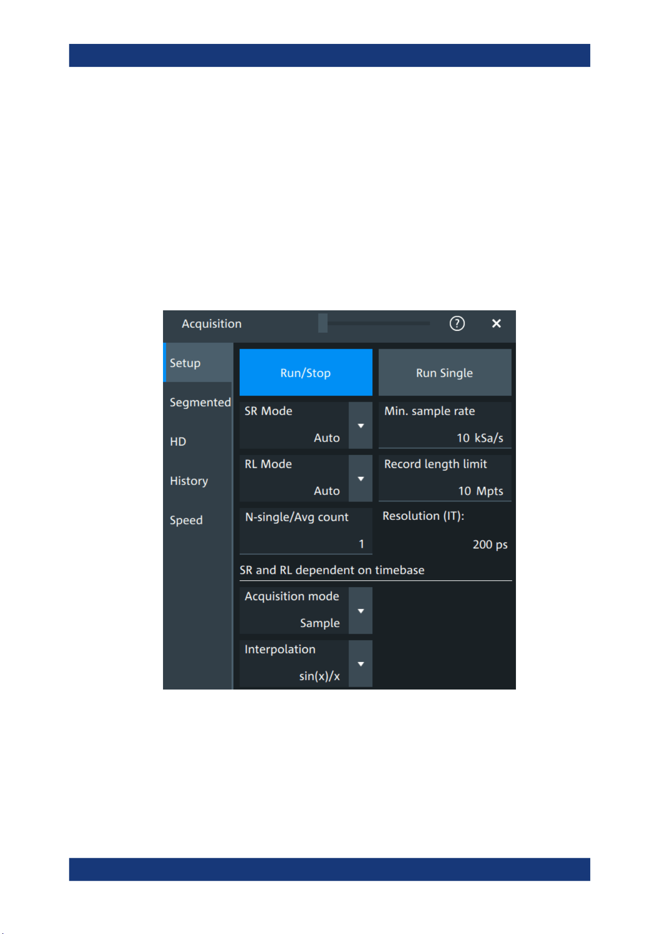
Acquisition and waveform setup
R&S
®
MXO 5 Series
106User Manual 1802.3369.02 ─ 02
The interleaved channels of an 8-channel oscilloscope are:
●
C1 and C5
●
C2 and C6
●
C3 and C7
●
C4 and C8
The 4-channel R&S MXO 5 is always in interleaving mode, and all 4 channels work
with 5 Gsample/s and maximum bandwidth.
6.2.2 Acquisition Setup settings
Access: "Menu" > "Acquisition" > "Setup" tab.
Figure 6-1: Acquisition settings: automatic sample rate and record length
Acquisition
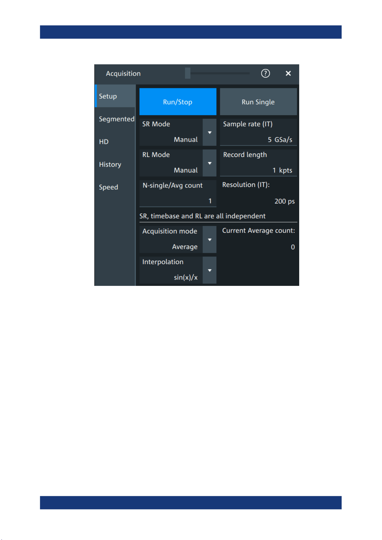
Acquisition and waveform setup
R&S
®
MXO 5 Series
107User Manual 1802.3369.02 ─ 02
Figure 6-2: Acquisition settings: manual sample rate and record length
Run/Stop
Starts and stops the continuous acquisition. The [Run / Stop] key lights green when the
acquisition is running. When the acquisition is stopped, the key lights red.
Remote command:
RUN on page 460
STOP on page 461
Run Single
Starts a defined number of acquisitions. The [Single] key lights green when the acquisi-
tion is running. When the acquisition is stopped, the key lights red.
To set the number of acquisitions, set "N-single/Avg count" in the "Acquisition" setup.
The acquisition progress is shown in the acquisition label, see "Progress information"
on page 66.
Remote command:
SINGle on page 460
SR mode
Defines how the sample rate is set.
Acquisition

Acquisition and waveform setup
R&S
®
MXO 5 Series
108User Manual 1802.3369.02 ─ 02
"Auto"
Sample rate is determined automatically and changes due to instru-
ment internal adjustments due to other setting changes.
"Manual"
The sample rate is manually defined with "Sample rate", "Min. sample
rate".
Remote command:
ACQuire:SRATe:MODE on page 475
RL mode
Selects the mode of the waveform record length adjustment.
"Auto"
Record length is determined automatically and changes due to instru-
ment internal adjustments due to other setting changes.
"Manual"
The waveform record length is manually defined with "Record length",
"Record length limit".
Remote command:
ACQuire:POINts:MODE on page 473
Sample rate, Min. sample rate
Sets the number of waveform points per second in manual sample rate mode. In auto-
matic sample rate mode, it sets the minimum value of the sample rate for automatic
calculation.
The sample rate considers the samples of the ADC, and the processing of the cap-
tured samples including interpolation.
The setting is relevant, if "SR mode" is set to "Manual".
Remote command:
ACQuire:SRATe[:VALue] on page 474
Record length, Record length limit
Sets the record length in manual record length mode. In automatic record length mode,
it sets the maximum value of the record length for automatic calculation.
The record length is the number of waveform samples that are stored in one waveform
record after processing, including interpolation.
Remote command:
ACQuire:POINts[:VALue] on page 473
N-single/Avg count
The acquisition and average count has several effects:
●
It sets the number of waveforms acquired with [Single].
●
It defines the number of waveforms used to calculate the average waveform.
Thus, the instrument acquires sufficient waveforms to calculate the correct average
if "Average" is enabled for waveform arithmetic. The higher the value is, the better
the noise is reduced.
●
It sets the number of acquisitions to be acquired in a fast segmentation acquisition
series, and in the history.
The setting is read-only if "Segmented" > "Acquire maximum" is "On". See also
"Acquire maximum" on page 110.
Acquisition

Acquisition and waveform setup
R&S
®
MXO 5 Series
109User Manual 1802.3369.02 ─ 02
Remote command:
ACQuire:COUNt on page 472
Resolution
Defines the time between two waveform samples in the waveform record. It considers
the processing of the captured samples including interpolation. A fine resolution with
low values produces a more precise waveform record.
The resolution is the reciprocal of the sample rate.
Remote command:
ACQuire:RESolution on page 474
Acquisition mode
Sets how the waveform is built from the captured samples.
"Sample"
Usually, most signals are displayed optimally with this acquisition
mode but very short glitches can remain undiscovered by this
method.
"Peak detect"
The minimum and the maximum of n samples are recorded as wave-
form points, the other samples are discarded. Thus the instrument
can detect fast signal peaks at slow time scale settings that would be
missed with other acquisition modes.
"Envelope"
Each acquisition is done in sample mode, and the minimum and max-
imum values over some consecutive acquisitions build the envelope.
"Average"
The average is calculated from the data of the current acquisition and
a specific number of consecutive acquisitions before. The method
reduces random noise. It requires a stable, triggered and repetitive
signal.
The number of acquisitions for average calculation is defined with N-
single/Avg count.
If the waveform is clipped, the instrument shows a distorted average
waveform to indicate the clipping. Adjust the vertical scale to avoid
the clipping. The acquisition progress is shown in the acquisition
label, see "Progress information" on page 66.
Remote command:
ACQuire:TYPE on page 475
Current Average count
Shows the current number of acquired waveforms that contribute to the average, for
Acquisition mode = "Average".
Remote command:
ACQuire:AVERage? on page 471
Interpolation
Selects the interpolation method.
If the defined sample rate ("Sample rate", "Min. sample rate") is higher than the ADC
sample rate, interpolation adds points between the captured samples of the waveform
by various mathematic methods. The selected interpolation method is also used for
zooming.
Acquisition
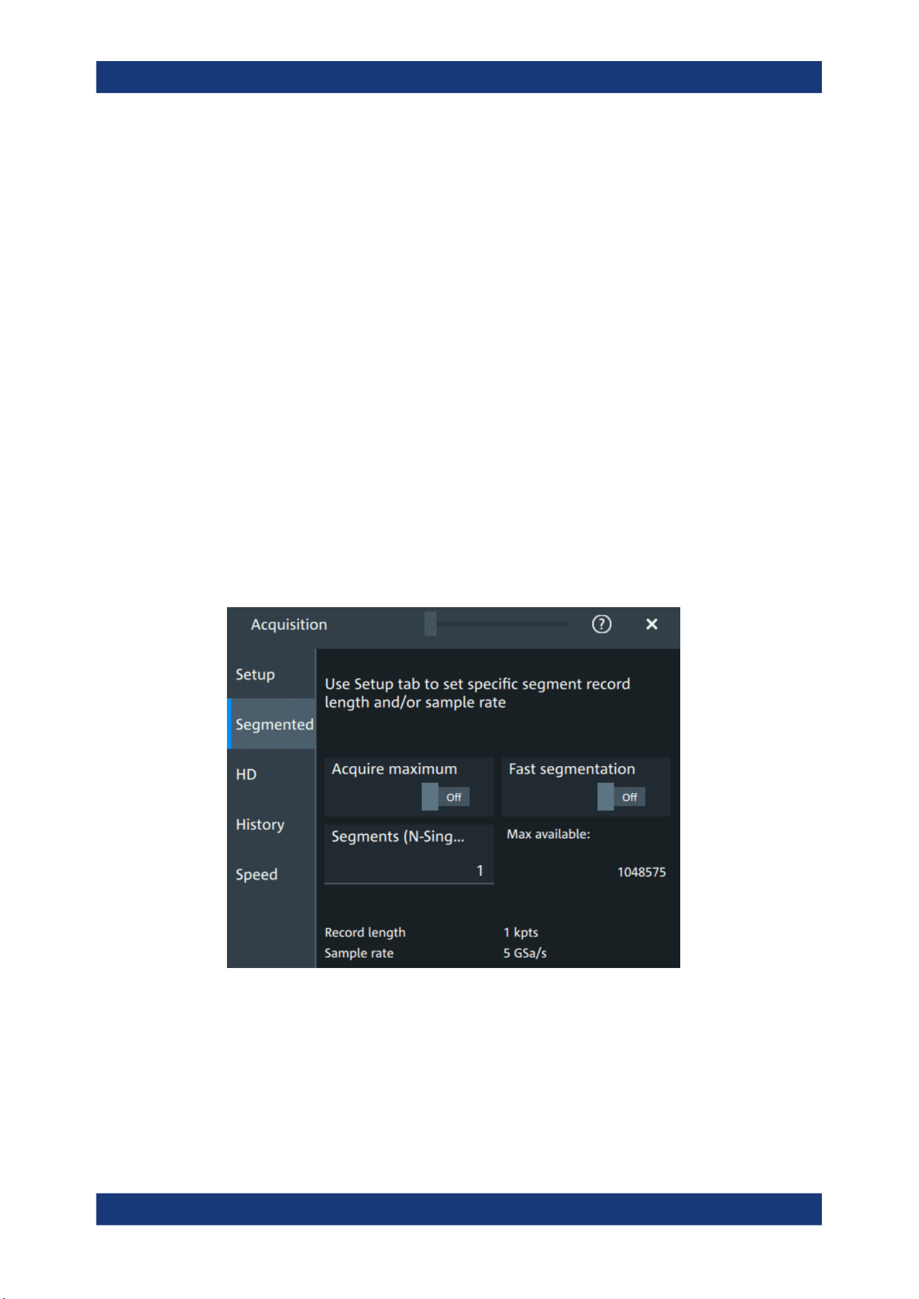
Acquisition and waveform setup
R&S
®
MXO 5 Series
110User Manual 1802.3369.02 ─ 02
"Linear"
Two adjacent ADC sample points are connected by a straight line, the
interpolated points are located on the line. You see a polygonal wave-
form similar to the real signal, and also the ADC sample points as
vertexes.
"sin (x)/x"
Two adjacent ADC sample points are connected by a sin(x)/x curve,
and also the adjoining sample points are considered by this curve.
The interpolated points are located on the resulting curve. This inter-
polation method is precise and shows the best signal curve.
"Sample/Hold"
The ADC sample points are displayed like a histogram. For each
sample interval, the voltage is taken from the sample point and con-
sidered as constant, and the intervals are connected with vertical
lines. Thus, you see the discrete values of the ADC - the measured
samples.
Remote command:
ACQuire:INTerpolate on page 472
6.2.3 Segmentation settings
Access: "Menu" > "Acquisition" > "Segmented" tab.
You can acquire a limited number of segments, or the maximum number.
Acquire maximum
The setting takes effect for N-single acquisitions ([Single]). During continuous acquisi-
tion ([Run / Stop]), the history is used completely.
If "On", "Segments (N-Single)" is set to the maximum number of available segments,
which is shown in "Max available". Thus, the history is filled completely with an N-sin-
gle acquisition. "Segments (N-Single)" is read-only, you cannot change the value.
Acquisition

Acquisition and waveform setup
R&S
®
MXO 5 Series
111User Manual 1802.3369.02 ─ 02
If "Off", set the number of segments in "Segments (N-Single)", which is the same set-
ting as "N-single/Avg count" on the "Setup" tab. Thus you can acquire a fast segmenta-
tion acquisition series and history of defined length with [Single].
You can stop the running acquisition before the series is completed.
The number of acquired waveforms is shown in the "History" dialog, when the history is
active.
Remote command:
ACQuire:SEGMented:MAX on page 476
Fast segmentation
If fast segmentation is enabled, the acquisitions are performed as fast as possible,
without processing and displaying the waveforms. When acquisition has been stopped,
the data is processed and the latest waveform is displayed. Older waveforms are
stored in segments. You can display and analyze the segments using the history.
Remote command:
ACQuire:SEGMented:STATe on page 476
Segments (N-Single)
See "N-single/Avg count" on page 108.
Max available
Shows the maximum number of segments that can be captured with current sample
rate and record length settings.
6.2.4 High definition mode
The high definition mode increases the numeric resolution of the waveform signal by
using digital filtering, leading to reduced noise. The higher vertical resolution reduces
quantization noise and acquires waveforms of higher accuracy with finer details of the
signal to be seen. The high definition is also applied to the digital trigger, thus the
R&S MXO 5 can trigger with the same high resolution with which they can display sig-
nals.
The maximum numeric resolution in high definition mode is 18 bit. The actual value
depends on the selected bandwidth. Increasing the bandwidth reduces the resulting
digital resolution. For dependencies and details, refer to the R&S MXO 5 specifica-
tions.
The number of vertical resolution bits defines the number of vertical levels that the
acquisition samples are mapped to (quantization). For example, 16 bits of resolution
represent 65536 voltage quantization levels, while 8 bits of resolution represent only
256 voltage levels. The waveform values are recorded with a word length of 16 bit,
except for peak detect decimation.
6.2.4.1 High definition settings
Access: [HD]
Acquisition
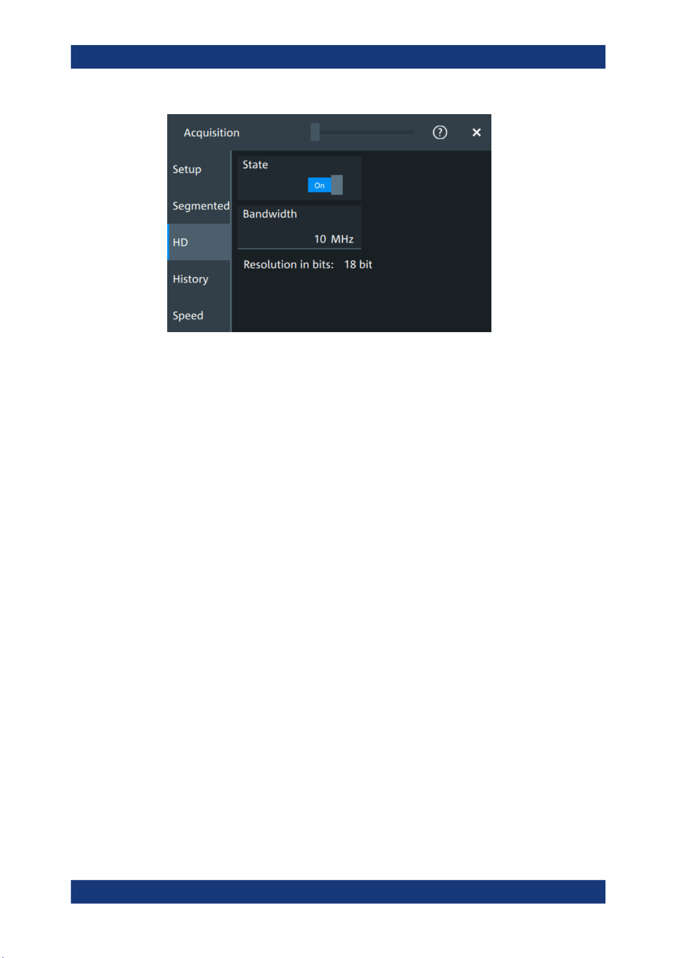
Acquisition and waveform setup
R&S
®
MXO 5 Series
112User Manual 1802.3369.02 ─ 02
High definition is a special acquisition mode of the oscilloscope. This mode has only
one setting - the filter bandwidth.
State
Enables high definition mode, which increases the numeric resolution of the waveform
signal.
Remote command:
HDEFinition:STATe on page 491
Bandwidth
Sets the filter bandwidth for the high definition mode.
Increasing the bandwidth reduces the resulting digital resolution. For dependencies
and details, refer to R&S MXO 5 specifications.
Remote command:
HDEFinition:BWIDth on page 491
Resolution in bits
Displays the resulting vertical resolution in high definition mode. The higher the filter
bandwidth, the lower the resolution.
Remote command:
HDEFinition:RESolution? on page 491
6.2.5 History settings
The history settings are described in Chapter 8.3.2, "History setup", on page 171.
6.2.6 Speed
Access: "Menu" > "Acquisition" > "Speed" tab.
Acquisition
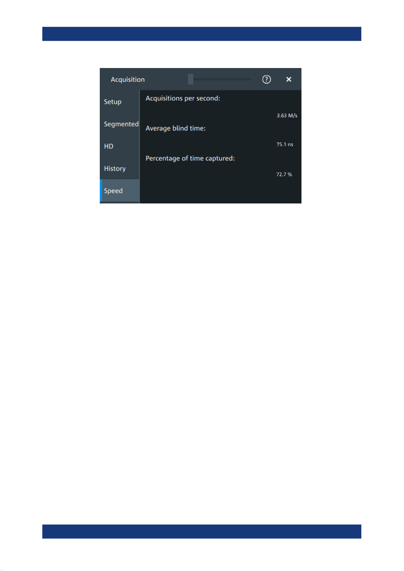
Acquisition and waveform setup
R&S
®
MXO 5 Series
113User Manual 1802.3369.02 ─ 02
The "Speed" dialog shows information on the current acquisition performance values of
the R&S MXO 5.
You can see the number of "Acquisitions per second", "Average blind time" and the
"Percentage of time captured".
6.3 Vertical setup
The controls and parameters of the vertical system adjust the vertical scale and posi-
tion of the waveform, and the waveform display. The probe settings also belong to the
vertical setup.
The signal icons at the bottom of the display show the most important actual settings
for each channel. The signal icon also indicates if the incoming data is clipped before
processing, i.e. the input range of the ADC is exceeded.
There are several ways to adjust vertical settings:
●
Use the keys and knobs in the Vertical functional block of the front panel to select
the channel, to scale the waveform, and to set the position or offset.
See Chapter 3.2.4.4, "Vertical controls", on page 37.
●
Drag one finger vertically on the screen to change the position of the selected
channel waveform.
●
Spread or pinch two fingers in vertical direction to change the vertical scale of the
selected waveform.
●
Use the "Vertical" dialog to adjust all vertical settings. See:
– Chapter 6.3.2, "Vertical Setup settings", on page 114
– Chapter 6.3.3, "Bandwidth settings", on page 117
– Chapter 6.4, "Probes", on page 119
– Chapter 6.3.5, "Other vertical settings", on page 118
Vertical setup

Acquisition and waveform setup
R&S
®
MXO 5 Series
114User Manual 1802.3369.02 ─ 02
6.3.1 About the vertical system
The controls and parameters of the vertical system are used to scale and position the
waveform vertically.
Vertical scale and resolution
Vertical scale and vertical position directly affect the resolution of the waveform ampli-
tude. The vertical scale corresponds to the ADC input range. To get the full resolution
of the ADC, set up the waveforms to cover most of the height of the diagram.
With an R&S MXO 5, you work with multiple diagrams, and each diagram obtains the
full vertical resolution, no matter where the diagram is placed. Therefore, use a sepa-
rate diagram for each waveform instead of the traditional setup that arranges the wave-
forms side by side in one diagram.
Bandwidth
For analog applications, the highest signal frequency determines the required oscillo-
scope bandwidth. The oscilloscope bandwidth should be higher than the maximum fre-
quency included in the analog test signal to measure the amplitude with very little mea-
surement error. To avoid aliasing, the oscilloscope bandwidth should be at least 3
times higher than the maximum frequency included in the signal.
Most test signals are more complex than a simple sine wave and include several spec-
tral components. A digital signal, for example, is built up of several odd harmonics. For
digital signals, the oscilloscope bandwidth should be at least 5 times higher than the
clock frequency to be measured.
The oscilloscope is not a stand-alone system. You need a probe to measure the signal
of interest, and the probe has a limited bandwidth, too. The combination of oscillo-
scope and probe creates a system bandwidth. To reduce the effect of the probe on the
system bandwidth, the probe bandwidth should exceed the bandwidth of the oscillo-
scope, the recommended factor is 1.5 x oscilloscope bandwidth.
6.3.2 Vertical Setup settings
Access: "Menu" > "Vertical" > "Setup" tab
The "Setup" tab provides all basic vertical settings. The channels are listed in horizon-
tal subtabs. Make sure to select the correct channel tab before you enter the settings.
Vertical setup
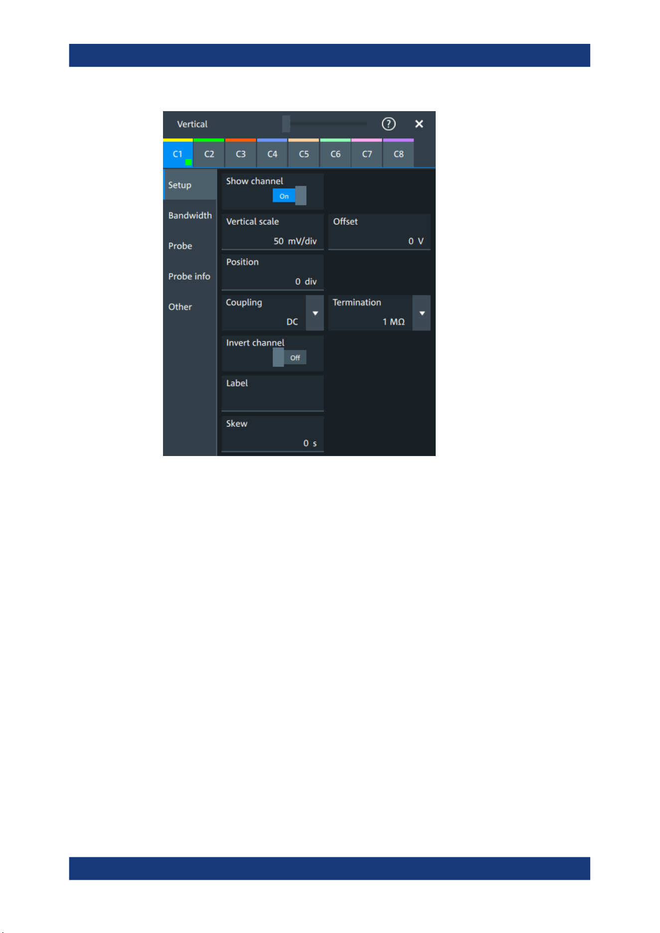
Acquisition and waveform setup
R&S
®
MXO 5 Series
115User Manual 1802.3369.02 ─ 02
Show channel
Switches the selected channel signal on or off.
The signal icon opens on the signal bar. The waveform of the last acquisition is dis-
played in the diagram.
Remote command:
CHANnel<ch>:STATe on page 464
Vertical scale
Sets the vertical scale, which defines the displayed amplitude of the selected wave-
form.
The unit depends on the connected probe.
The current value is shown in the signal icon. Vertical scale directly affects the resolu-
tion of the waveform amplitude. To get the best resolution of the ADC, set the wave-
forms to cover most of the height of the diagram.
Remote command:
CHANnel<ch>:SCALe on page 465
Offset
Sets the offset voltage, which corrects an offset-affected signal. The vertical center of
the selected channel is shifted by the offset value and the signal is repositioned within
the diagram.
Vertical setup

Acquisition and waveform setup
R&S
®
MXO 5 Series
116User Manual 1802.3369.02 ─ 02
To set the offset automatically, use [Autoset]. The current value is shown in the signal
icon.
Use the offset to measure small AC voltages that are overlaid by higher DC voltages.
Unlike AC coupling, the DC part of the signal is not lost with offset setting.
If an active probe is connected, the offset limit is defined by the probe. Refer to the
documentation of the probe for allowed values.
If a Rohde & Schwarz differential probe is connected, set the common-mode offset to
compensate for a common DC voltage applied to both input sockets (referenced to the
ground socket). Thus, you can measure on differential signals with high common mode
levels. You can measure the common mode input voltage using the R&S ProbeMeter.
Remote command:
CHANnel<ch>:OFFSet on page 465
Position
Moves the selected signal up or down in the diagram. While the offset sets a voltage,
position is a graphical setting given in divisions. The visual effect is the same as for off-
set.
Remote command:
CHANnel<ch>:POSition on page 466
Coupling
Sets the filter for the input signal. The coupling determines what part of the signal is
used for waveform analysis and triggering.
The selected coupling is shown in the signal icon.
"DC"
Passes both DC and AC components of the signal.
"AC"
Connection through DC capacitor, removes DC and very low-fre-
quency components. AC coupling is useful if the DC component of a
signal is of no interest. The waveform is centered on zero volts.
If AC coupling is set, the attenuation of passive probes has no effect,
and voltage is applied to the instrument with factor 1:1. Observe the
voltage limits, otherwise you can damage the instrument.
Remote command:
CHANnel<ch>:COUPling on page 466
Termination
Selects the input impedance of the channel input according to the connected probe.
Connection with 50 Ω termination is used to connect, for example, active probes. Con-
nection with 1 MΩ termination is used to connect standard passive probes.
Remote command:
CHANnel<ch>:COUPling on page 466
Invert channel
Turns the inversion of the signal amplitude on or off. To invert means to reflect the volt-
age values of all signal components against the ground level.
Inversion is indicated in the signal icon by line above the channel name.
Vertical setup
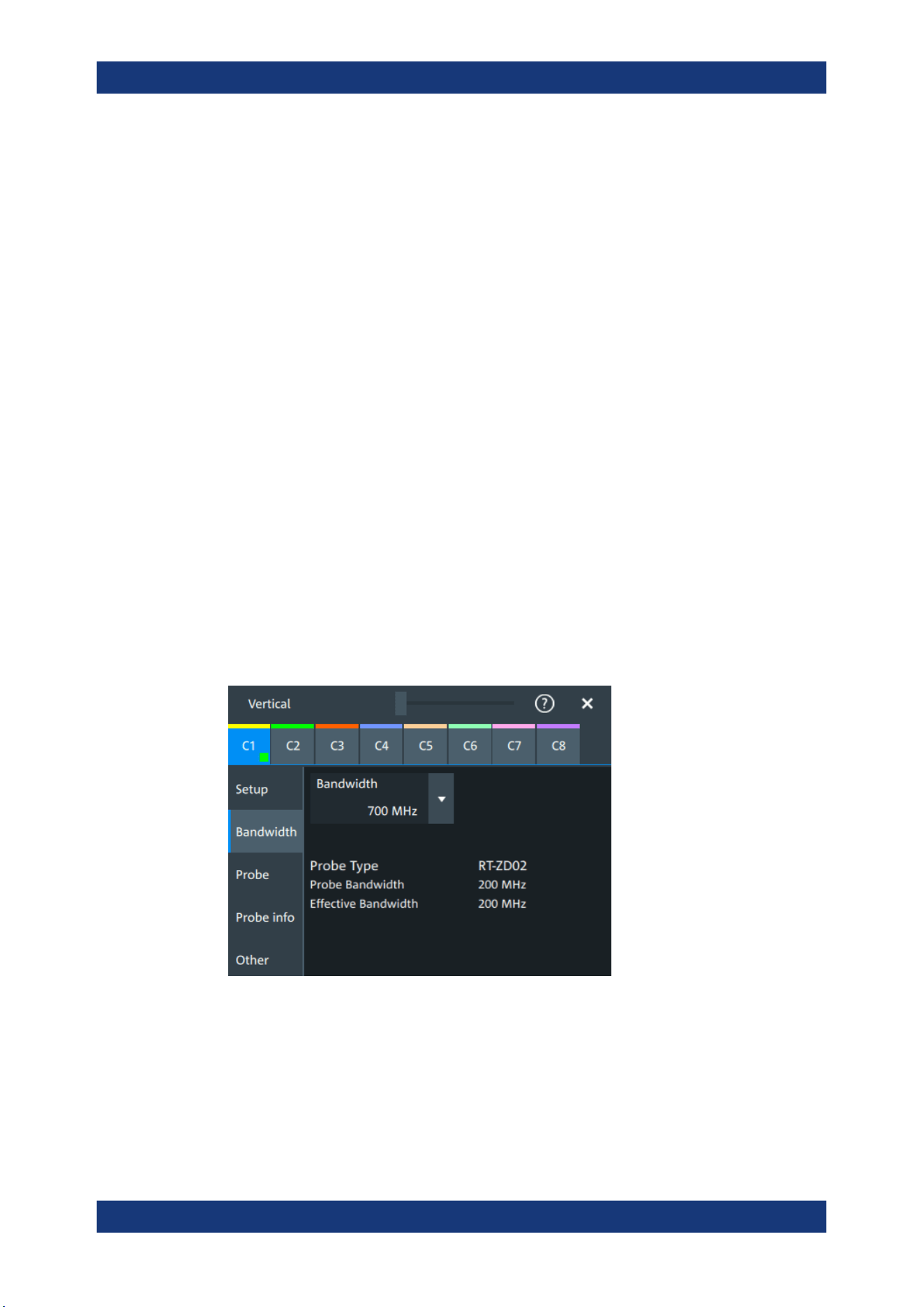
Acquisition and waveform setup
R&S
®
MXO 5 Series
117User Manual 1802.3369.02 ─ 02
Remote command:
CHANnel<ch>:INVert on page 467
Label
Defines a label text. The label is shown at the waveform on the right edge of the dis-
play.
Skew
Sets a skew value to compensate for the delay of the measurement setup or from the
circuit specifics that the instrument cannot compensate automatically. It affects only the
selected input channel.
Delay differences between channels are caused by the different length of cables,
probes, and other sources. Correct deskew values are important for accurate trigger-
ing. Signals that are routed over lines with different lengths have a different propaga-
tion delay. This delay can lead to a non-synchronous waveform display.
Remote command:
CHANnel<ch>:SKEW:TIME on page 467
6.3.3 Bandwidth settings
Access: "Menu" > "Vertical" > "Bandwidth" tab
The "Bandwidth" tab provides all settings that affect the bandwidth of the measurement
system. The channels are listed in horizontal subtabs. Make sure to select the correct
channel tab before you enter the settings.
Bandwidth
Sets the bandwidth limit. The specified bandwidth indicates the range of frequencies
that the instrument can acquire and display accurately with less than 3 dB attenuation.
Frequencies above the limit are removed from the signal, and noise is reduced.
The selected bandwidth is shown on the signal icon.
For basic information, see also: "Bandwidth" on page 114.
Vertical setup
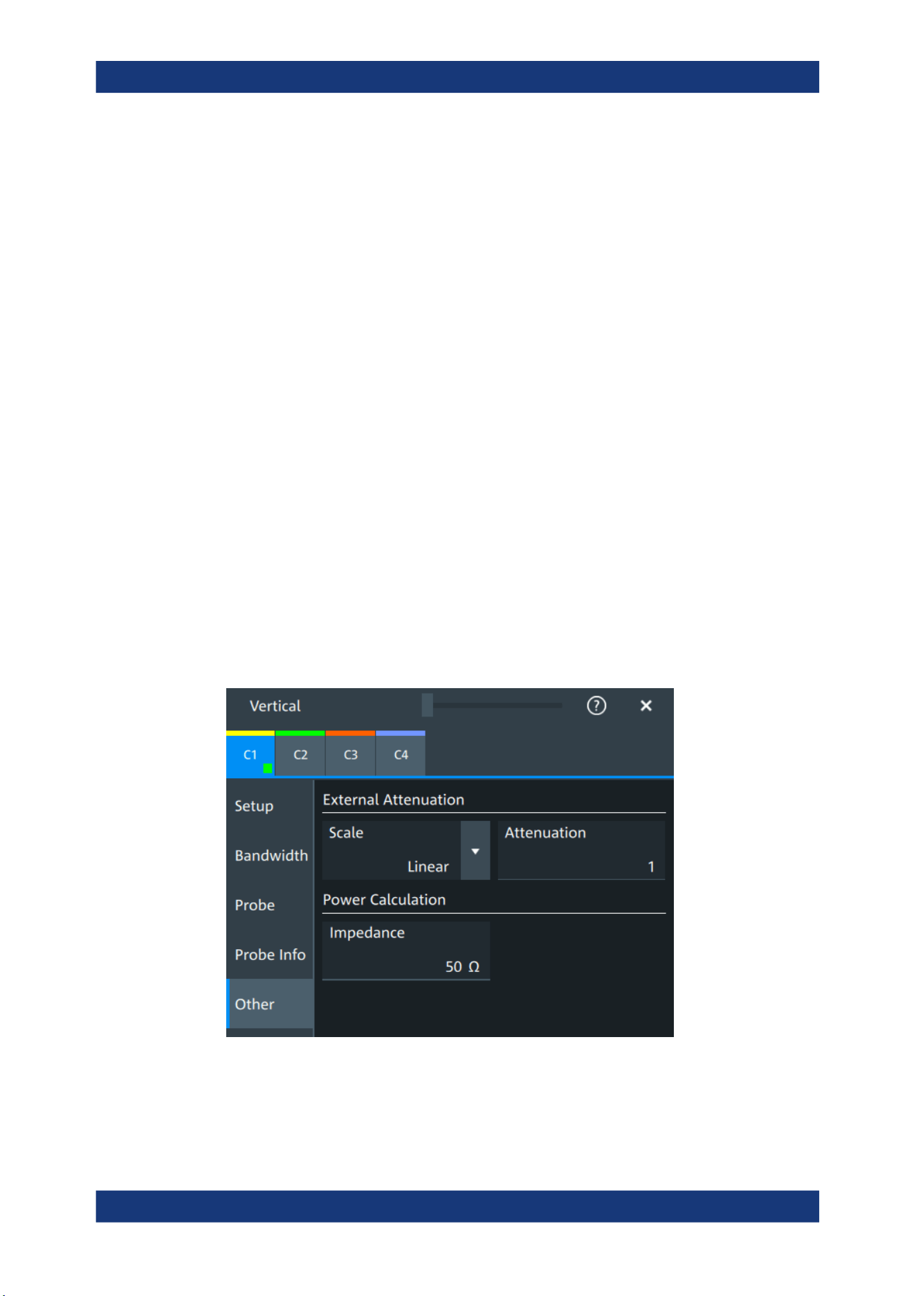
Acquisition and waveform setup
R&S
®
MXO 5 Series
118User Manual 1802.3369.02 ─ 02
"Full"
At full bandwidth, all frequencies in the instrument's frequency range
are acquired and displayed. Full bandwidth is used for most applica-
tions. However, at full bandwidth, the displayed bandwidth can be
less than the instrument bandwidth depending on the number of
active channels and other settings.
"xx MHz"
Frequencies above the selected limit are removed to reduce noise.
Remote command:
CHANnel<ch>:BANDwidth on page 468
Probe type, Probe bandwidth
Shows the type of the connected probe and its bandwidth. The probe is recognized
automatically, or selected in the "Probe" tab. See Chapter 6.4.1, "Common probe set-
tings", on page 119.
Effective bandwidth
Shows the effective bandwidth of probe and oscilloscope system.
6.3.4 Probe settings
See Chapter 6.4, "Probes", on page 119.
6.3.5 Other vertical settings
Access: "Menu" > "Vertical" > "Other" tab
Vertical setup

Acquisition and waveform setup
R&S
®
MXO 5 Series
119User Manual 1802.3369.02 ─ 02
External Attenuation: Scale, Attenuation
Consider a voltage divider that is part of the DUT before the measuring point. The
external attenuation is included in the measurement, and the instrument shows the
results that would be measured before the divider. External attenuation can be used
with all probes.
"Scale"
Select linear or logarithmic attenuation scale.
"Attenuation"
Enter the attenuation of the voltage divider according to the selected
scale. The conversion from linear to logarithmic values depends on
the "Vertical unit" of the probe:
For voltage-based unit (V and A):
attenuation (dB) = 20 * log
10
(attenuation factor)
For power-based unit (W):
attenuation (dB) = 10 * log
10
(attenuation factor)
Remote command:
CHANnel<ch>:EATScale on page 468
CHANnel<ch>:EATTenuation on page 468
Impedance
Sets the impedance of the connected probe for power calculations and measurements.
The value is used, for example, for scale calculation in the spectrum diagram.
Remote command:
CHANnel<ch>:IMPedance on page 469
6.4 Probes
With R&S MXO 5 oscilloscopes, you can use various probe types. Mostly these probes
are passive and active voltage probes. The instrument can detect many probes and
read out the probe-specific parameters, for example, bandwidth and attenuation.
You find all settings that are relevant for the connected probe in the "Vertical" > "Probe"
tab. The settings on the "Probe" tab change according to the type of the attached
probe. Probes with Rohde & Schwarz probe interface (probe box), and also many
other passive voltage probes, are recognized by the instrument. The R&S MXO 5
reads out the main characteristics of the probe and displays them. Other probes can-
not be detected, but their characteristics are known to the instrument. These known
probes are called "Predefined probes". Probes that are not recognized automatically
and not predefined are unknown probes, they require manual setting of measurement
unit and attenuation.
The complete characteristic of the connected probe is shown on the "Vertical" > "Probe
Info" tab.
6.4.1 Common probe settings
Access: "Menu" > "Vertical" > "Probe" tab
Probes
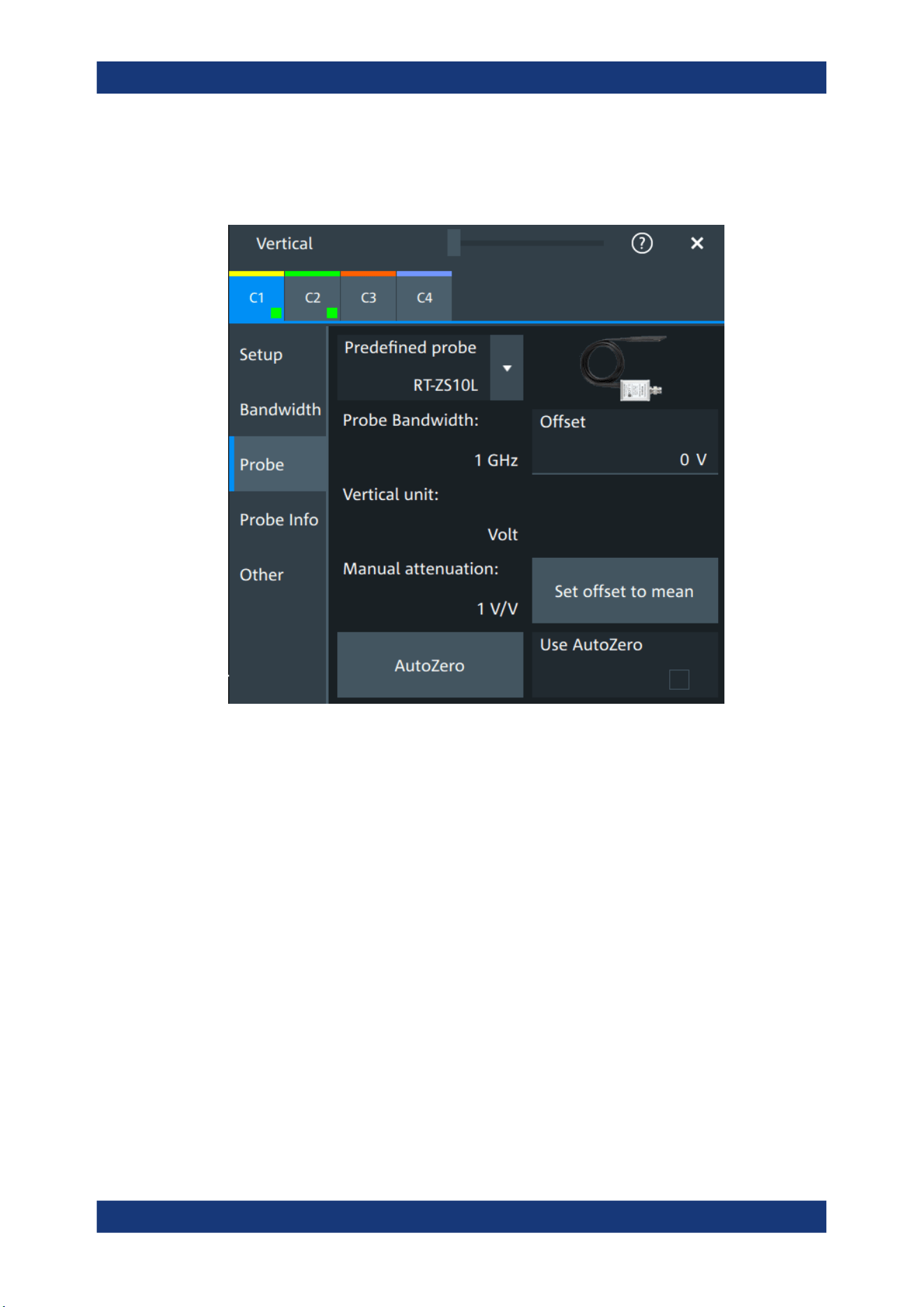
Acquisition and waveform setup
R&S
®
MXO 5 Series
120User Manual 1802.3369.02 ─ 02
Most the settings in the "Probe" tab are available for all probes. For some probe types,
additional settings are needed. These settings are described in the sections for the
individual probe types.
An external attenuation can be set on the "Other" tab, see Chapter 6.3.5, "Other verti-
cal settings", on page 118.
The common probe settings are:
Predefined probe, name and type of the probe...........................................................120
Probe bandwidth......................................................................................................... 121
Offset...........................................................................................................................121
Vertical unit..................................................................................................................121
Manual attenuation......................................................................................................121
Set offset to mean....................................................................................................... 121
AutoZero, Use AutoZero............................................................................................. 122
Predefined probe, name and type of the probe
The model name and type of a detected probe are shown in the dialog.
If the instrument cannot recognize the probe, "None" is indicated in the "Predefined
probe" list. Select the used probe on the list. The corresponding bandwidth, and
attenuation or gain are shown.
If the probe is not detected and not listed as predefined probe, it is an unknown probe.
To configure these probes, set "Predefined probe" to "User-Defined". Then adjust the
Vertical unit and Manual attenuation.
Probes

Acquisition and waveform setup
R&S
®
MXO 5 Series
121User Manual 1802.3369.02 ─ 02
Remote command:
PROBe<ch>:SETup:NAME? on page 480
PROBe<ch>:SETup:TYPE? on page 480
PROBe<ch>:SETup:STATe? on page 480
PROBe<ch>:SETup:ATTenuation:DEFProbe on page 477
Probe bandwidth
Shows the bandwidth of the connected probe. For probes that are not detected or pre-
defined, set the bandwidth manually.
Remote command:
PROBe<ch>:SETup:BANDwidth? on page 478
Offset
Channel offset that is also set on "Vertical" > "Setup" tab. See "Offset" on page 115.
Vertical unit
Shows the unit of the connected probe if the probe is detected or predefined. For
unknown probes, select the unit that the probe can measure.
Remote command:
PROBe<ch>:SETup:ATTenuation:UNIT on page 478
Manual attenuation
Shows the attenuation of the connected probe if the probe is detected or predefined.
For unknown probes, set the correct attenuation of the probe.
The vertical scaling and measured values are multiplied by this factor so that the dis-
played values are equal to the actual measured signal values.
Make sure to set the attenuation factor on the instrument according to the probe being
used. Otherwise, the measurement results do not reflect the actual voltage level, and
you might misjudge the actual risk.
Remote command:
PROBe<ch>:SETup:ATTenuation[:AUTO]? on page 477
PROBe<ch>:SETup:ATTenuation:MANual on page 477
Set offset to mean
Compensates automatically for a DC component of the input signal using the result of
a background mean measurement.
The result is shown in "Offset". The function is probe-independent and supports quick
and convenient measurements of input signals with different DC offsets. It detects off-
set values even when the signal is out of the current measurement range. It also sets
the zero level to the determined DC offset in the middle of the screen and thus pre-
vents clipping of the waveform.
Remote command:
PROBe<ch>:SETup:OFFSet:TOMean on page 479
Probes

Acquisition and waveform setup
R&S
®
MXO 5 Series
122User Manual 1802.3369.02 ─ 02
AutoZero, Use AutoZero
Differences in DUT and oscilloscope ground levels can cause larger zero errors, which
affect the waveform. If the DUT is ground-referenced, the AutoZero function corrects
the zero error of the probe to optimize measurement results at small signal levels. The
validation limit depends on the probe attenuation because probes with high attenuation
often have to compensate high offsets. AutoZero detects offset values even when the
signal is out of the current measurement range.
To correct the zero error of voltage probes, short the signal pin and the ground pin
together and connect them to the ground of the DUT. Then tap "AutoZero". While the
alignment is running, the instrument switches to DC coupling to display the waveform
correctly.
To include the measured offset in measurement results, enable "Use AutoZero".
If a current probe is connected, the function demagnetizes the probe's sensor head
and sets the waveform to zero position.
Remote command:
PROBe<ch>:SETup:OFFSet:AZERo on page 479
PROBe<ch>:SETup:OFFSet:USEautozero on page 479
6.4.2 Setup for passive probes
Passive probes are the most widely used probes for voltage measurements with oscil-
loscopes. If a passive probe is connected, the probe attenuation is read out and shown
in the "Probe" tab.
Passive probes require compensation, see Chapter 6.4.6, "Adjusting passive probes",
on page 132.
Probes
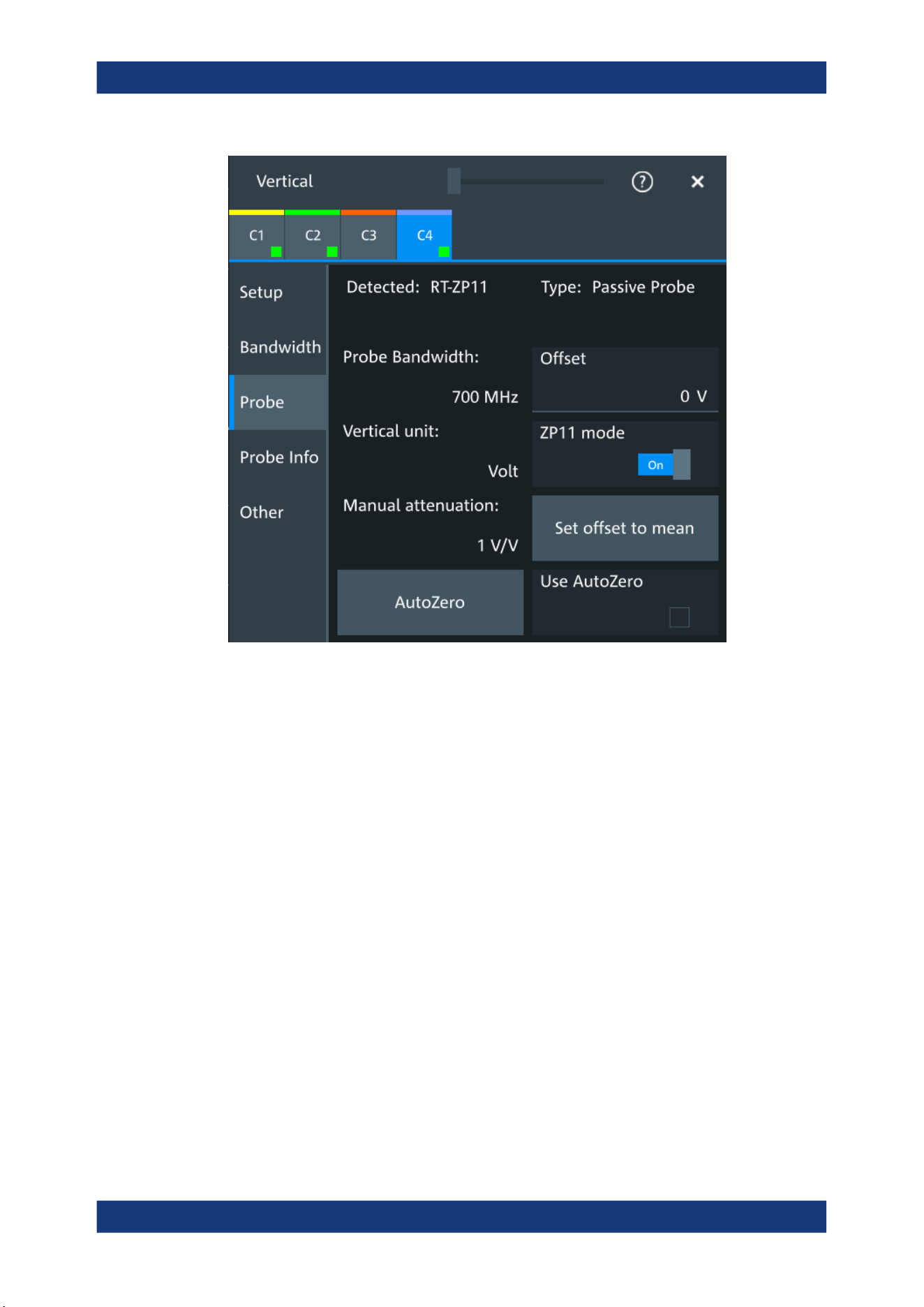
Acquisition and waveform setup
R&S
®
MXO 5 Series
123User Manual 1802.3369.02 ─ 02
Figure 6-3: Passive probe R&S
RT-ZP11, detected by the oscilloscope
The settings for passive probes are common settings, which are available for all probe
types. See Chapter 6.4.1, "Common probe settings", on page 119 for description of the
settings.
For R&S RT-ZP11, a special setting is available.
ZP11 mode
Enable if R&S RT-ZP11 is connected to adjust the probe bandwidth to 700 MHz.
If you use 500 MHz passive probe, e.g. R&S RT-ZP10, disable the setting.
6.4.3 Setup for active voltage probes
Active voltage probes with Rohde & Schwarz probe interface have an integrated data
memory that contains identification data and individual probe correction parameters.
The R&S MXO 5 can detect these probes and read out the data. Furthermore, the
Rohde & Schwarz probe interface provides special features: the micro button and the
ProbeMeter.
Active voltage probes that are offered by Rohde & Schwarz but not equipped with a
Rohde & Schwarz probe interface are known to the R&S MXO 5 as predefined probes.
Probes

Acquisition and waveform setup
R&S
®
MXO 5 Series
124User Manual 1802.3369.02 ─ 02
6.4.3.1 Settings for the Rohde & Schwarz probe interface
The Rohde & Schwarz probe interface provides special features: the micro button and
the ProbeMeter.
MicroButton
The micro button is located on the probe head. Pressing this button, you initiate an
action on the instrument directly from the probe. The button is disabled during internal
automatic processes, for example, during self-alignment, autoset, and level detection.
Select the action that you want to start from the probe.
"Run Continuous"
Starts or stops the acquisition (same as Run / Stop key).
"Run single"
Starts a defined number of acquisitions (same as [Single] key).
"Auto set"
Starts the autoset procedure (same as Autoset key).
"AutoZero"
Starts an auto zero measurement.
"Set offset to mean"
Performs an automatic compensation for a DC component of the
input signal using the result of a background mean measurement.
"Save image to file"
Saves the current display as image according to the image settings.
"No action"
Select this option to prevent unwanted actions due to unintended
usage of the micro button.
"Find trigger
level"
Sets the trigger level automatically to 0.5 * (MaxPeak – MinPeak).
"Probe Setup"
Opens the probe setup on the screen.
Remote command:
PROBe<ch>:SETup:MODE on page 481
ProbeMeter
Activates the integrated R&S ProbeMeter on probes with Rohde & Schwarz probe
interface.
The R&S ProbeMeter is a voltmeter. It measures DC voltages between the probe tip
and ground connection or between the probe tips with very high precision. The mea-
surement runs continuously and in parallel to the measurements of the oscilloscope.
If a single-ended or power rail probe is connected, the ProbeMeter measures DC vol-
tages between the probe tip and ground connection and enables ground-referenced
measurements of voltages.
If a differential probe is connected, you can select if the ProbeMeter measures differen-
tial and common mode voltages, or single-ended voltages. See "Display" on page 126.
Remote command:
PROBe<ch>:PMETer:STATe on page 483
PROBe<ch>:PMETer:RESults:SINGle? on page 484
PROBe<ch>:PMETer:RESults:COMMon? on page 484
PROBe<ch>:PMETer:RESults:DIFFerential? on page 484
Probes
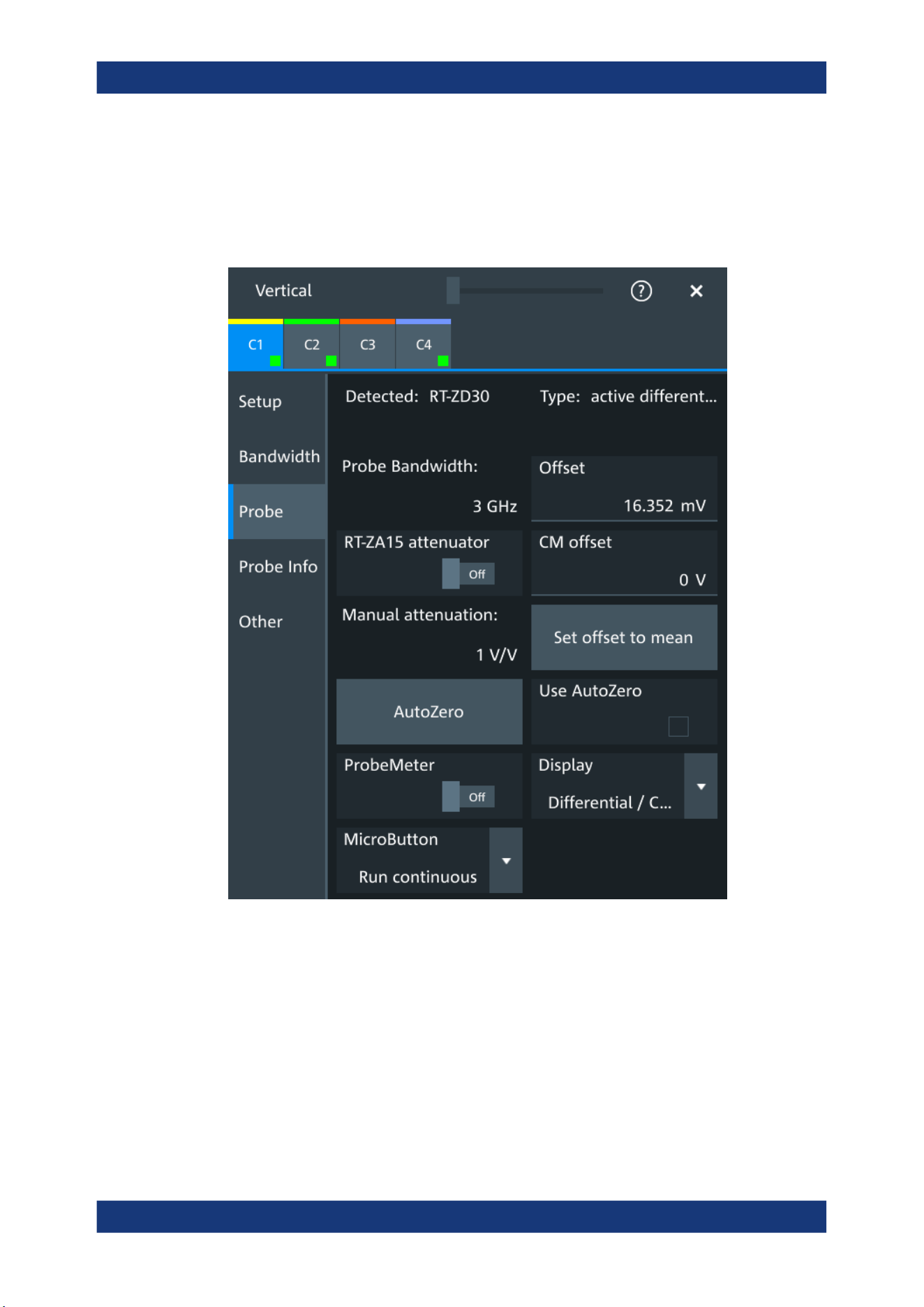
Acquisition and waveform setup
R&S
®
MXO 5 Series
125User Manual 1802.3369.02 ─ 02
PROBe<ch>:PMETer:RESults:NEGative? on page 485
PROBe<ch>:PMETer:RESults:POSitive? on page 485
6.4.3.2 Setup for R&S RT-ZD differential probes
Figure 6-4: Probe setup for active differential probe R&S
RT-ZD30
Most settings are common settings, which are available for all probe types. See Chap-
ter 6.4.1, "Common probe settings", on page 119 for description of these settings.
R&S RT-ZD differential probes have the Rohde & Schwarz probe interface and support
its functions. For details, see Chapter 6.4.3.1, "Settings for the Rohde & Schwarz
probe interface", on page 124.
The "Offset" is the differential offset, see "Offset" on page 115.
Specific settings for R&S RT-ZD probes are the following:
Probes

Acquisition and waveform setup
R&S
®
MXO 5 Series
126User Manual 1802.3369.02 ─ 02
CM offset
Sets the common-mode offset to compensate for a common DC voltage that is applied
to both input sockets (referenced to the ground socket). The setting is available for
Rohde & Schwarz differential probes.
Offset compensation is particularly helpful for measurements on differential signals with
high common mode levels, for example, current measurements using a shunt resistor.
You can measure the common mode input voltage using the R&S ProbeMeter.
Remote command:
PROBe<ch>:SETup:CMOFfset on page 482
RT-ZA15 attenuator
If you use the external attenuator R&S RT-ZA15 together with one of the differential
active probes R&S RT-ZD10/20/30, enable "RT-ZA15 attenuator" to include the exter-
nal attenuation in the measurements.
Remote command:
PROBe<ch>:SETup:ZAXV on page 483
Display
Selects the voltage to be measured by the ProbeMeter of differential active probes:
●
"Differential / Common Mode":
Differential voltage is the voltage between the positive and negative signal sockets.
Common mode voltage is the mean voltage between the signal sockets and the
ground socket. It measures the voltage level relative to ground, for example, to
check the operating voltage window.
●
"Single Ended Pos/Neg":
Measures the voltage between the positive/negative signal socket and the ground.
The ProbeMeter always measures the common mode and differential voltages.
Single-ended voltages are calculated values:
V
p
= V
cm
+ 0.5 * V
in
and V
n
= V
cm
- 0.5 * V
in
Remote command:
PROBe<ch>:SETup:DISPlaydiff on page 483
6.4.3.3 Setup for R&S RT‑ZPR power rail probes
R&S RT‑ZPR power rail probes are designed for power integrity measurements. They
can measure small signals in the millivolt range with large DC-offset components.
R&S RT‑ZPR power rail probes have the Rohde & Schwarz probe interface and sup-
port the ProbeMeter, but not the micro button. For details, see Chapter 6.4.3.1, "Set-
tings for the Rohde & Schwarz probe interface", on page 124.
R&S RT‑ZPR probes require 50 Ω input termination.
Probes
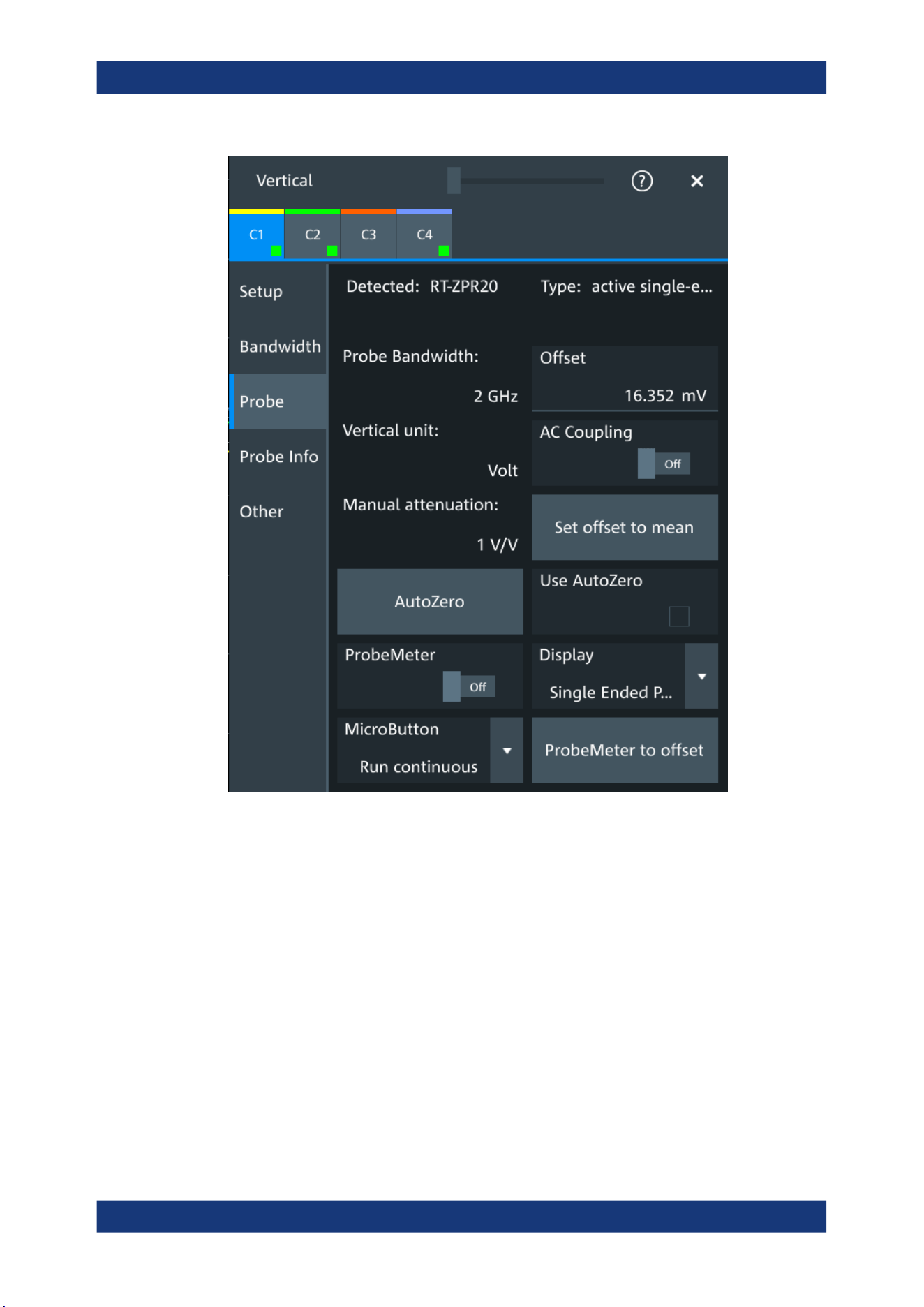
Acquisition and waveform setup
R&S
®
MXO 5 Series
127User Manual 1802.3369.02 ─ 02
Figure 6-5: Probe setup for power rail probe R&S
RT
‑
ZPR20
Most settings are common settings, which are available for all probe types. See Chap-
ter 6.4.1, "Common probe settings", on page 119 for description of these settings.
The "Offset" is the channel offset, see "Offset" on page 115.
Specific settings for R&S RT‑ZPR probe are the following:
AC Coupling
Enables AC coupling in R&S RT‑ZPR power rail probes, which removes DC and very
low-frequency components. The R&S RT‑ZPR probe requires 50 Ω input termination,
for which the channel AC coupling is not available. The probe setting allows AC cou-
pling also at 50 Ω inputs.
Remote command:
PROBe<ch>:SETup:ACCoupling on page 482
Probes
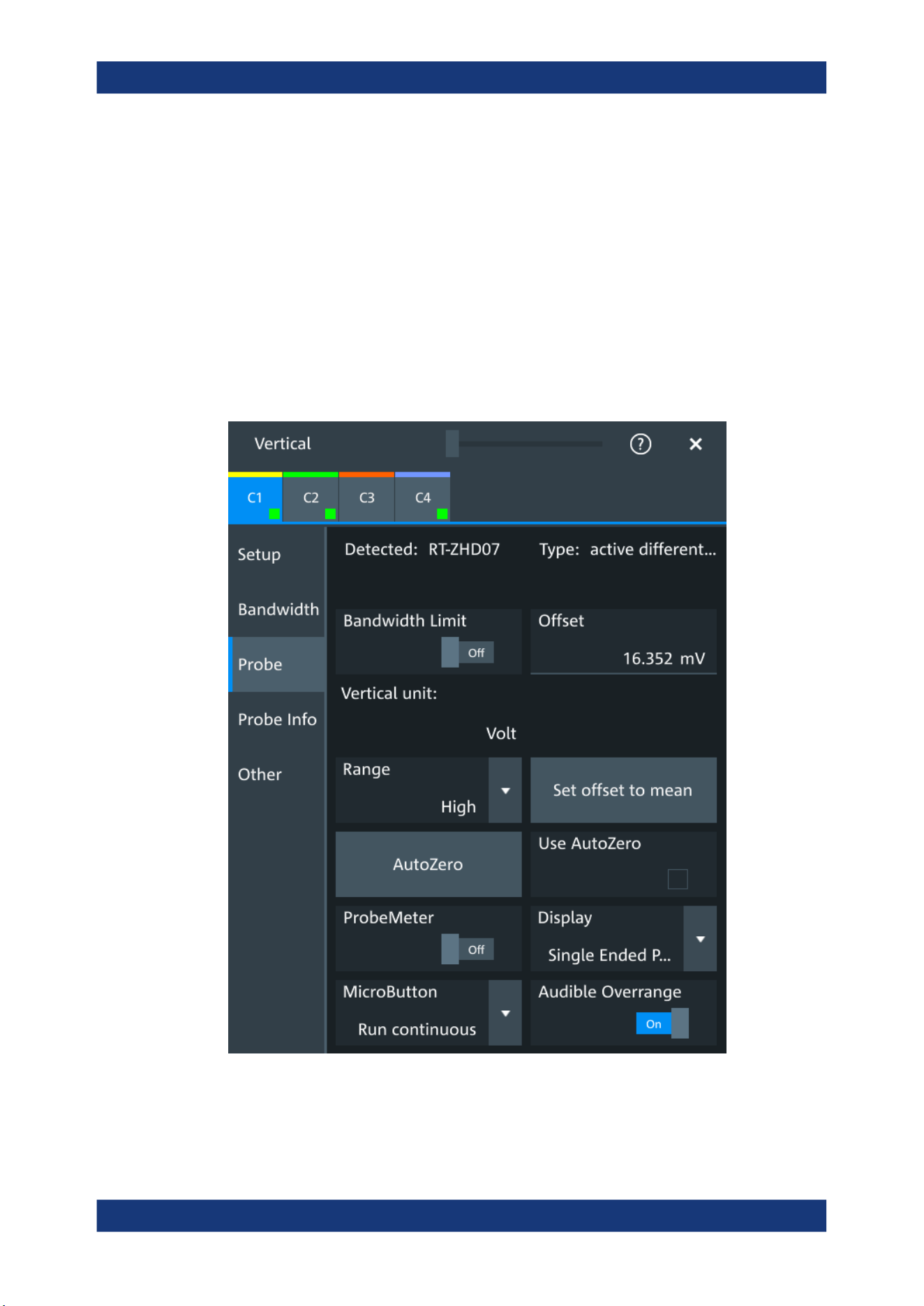
Acquisition and waveform setup
R&S
®
MXO 5 Series
128User Manual 1802.3369.02 ─ 02
ProbeMeter to offset
Sets the measured ProbeMeter value as offset. Thus, the value is considered in mea-
surements.
Remote command:
PROBe<ch>:SETup:ADVanced:PMToffset on page 487
6.4.3.4 Setup for R&S RT-ZHD high-voltage differential probes
R&S RT-ZHD high-voltage differential probes are designed to measure safely high-volt-
age floating circuits using a grounded oscilloscope. They extend the measurement
capability of oscilloscopes to measure electronic power converters, inverters, motor
speed controls, switch mode power supplies and many other applications.
Figure 6-6: Setup for high-voltage differential probe R&S
RT-ZHD07
Most settings are common settings, which are available for all probe types. See Chap-
ter 6.4.1, "Common probe settings", on page 119 for description of these settings.
Probes

Acquisition and waveform setup
R&S
®
MXO 5 Series
129User Manual 1802.3369.02 ─ 02
Bandwidth and attenuation values are indicated on the probe control box. The "Offset"
is the differential offset, see "Offset" on page 115.
R&S RT-ZHD high-voltage differential probes have the Rohde & Schwarz probe inter-
face and support its functions. For details, see Chapter 6.4.3.1, "Settings for the
Rohde & Schwarz probe interface", on page 124.
Specific settings for R&S RT-ZHD probes are the following:
Bandwidth limit
Activates the lowpass filter in the probe control box. The filter frequency depends on
the probe type and is indicated on the probe control box.
You can set the filter on the probe control box or at the oscilloscope.
Remote command:
PROBe<ch>:SETup:ADVanced:FILTer on page 486
Range
Sets the voltage range of an R&S RT-ZHD probe. You can set the range on the probe
control box or at the oscilloscope.
"Auto"
The voltage range is set only at the oscilloscope with "Vertical scale".
"Low"
Sets the lower voltage range of the connected probe. The range val-
ues depend on the probe type and are indicated on the probe control
box.
"High"
Sets the higher voltage range of the connected probe. The range val-
ues depend on the probe type and are indicated on the probe control
box.
Remote command:
PROBe<ch>:SETup:ADVanced:RANGe on page 486
Audible overrange
Activates the acoustic overrange warning in the probe control box. You can also acti-
vate the sound directly on the probe control box.
Remote command:
PROBe<ch>:SETup:ADVanced:AUDioverload on page 486
6.4.4 Setup for current probes
The setup and adjustment of current probes depends on the output connector of the
probe: BNC or Rohde & Schwarz probe box.
Current probes R&S RT-ZCxx
The current probes R&S RT-ZCxx have BNC connectors. They are known to the
R&S MXO 5 as predefined probes, see "Predefined probe, name and type of the
probe" on page 120. Demagnetizing and zero adjustment is done on the probe, see the
probe's User Manual for details. Make sure to demagnetize and adjust the probe
before taking measurements.
Probes
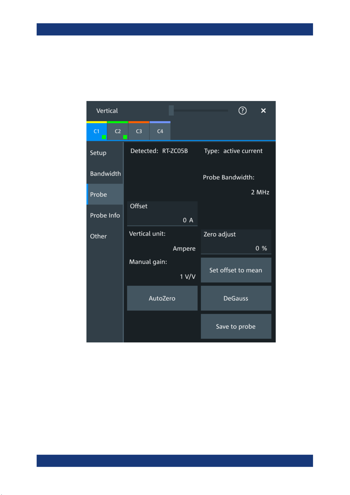
Acquisition and waveform setup
R&S
®
MXO 5 Series
130User Manual 1802.3369.02 ─ 02
Current probes R&S RT-ZCxxB
Current probes R&S RT-ZCxxB have a Rohde & Schwarz probe interface; they are
powered and remotely controlled by the oscilloscope.
When the probe is connected, demagnetization is performed automatically.
Figure 6-7: Setup for current probe R&S
RT-ZC05B
Most settings are common settings, which are available for all probe types. See Chap-
ter 6.4.1, "Common probe settings", on page 119 for description of these settings.
Current probes are adjusted by the following functions.
Gain, Manual gain
Shows the gain of the connected probe if the probe is detected or predefined. For
unknown current probes, set the correct gain of the probe.
Probes

Acquisition and waveform setup
R&S
®
MXO 5 Series
131User Manual 1802.3369.02 ─ 02
The vertical scaling and measured values are multiplied by this factor so that the dis-
played values are equal to the actual measured signal values.
Remote command:
PROBe<ch>:SETup:GAIN:AUTO? on page 487
PROBe<ch>:SETup:GAIN:MANual on page 487
DeGauss
Demagnetizes the core if it has been magnetized by switching the power on and off, or
by an excessive input. Always carry out demagnetizing before measurement.
The demagnetizing process takes about one second. During demagnetizing, a demag-
netizing waveform is displayed.
Demagnetizing is done automatically when R&S RT-ZCxxB is connected to the oscillo-
scope, or when "AutoZero" is performed.
Remote command:
PROBe<ch>:SETup:DEGauss on page 488
Zero adjust
Zero adjust corrects the effect of an offset caused by temperature drift, and compen-
sates for the remanence. The setting is only available if DC coupling is set.
To set the waveform to zero level by the instrument, use "AutoZero". The detected
value is displayed.
Alternatively, you can adjust the value manually until the waveform is set to zero level.
Make sure to demagnetize the probe before zero adjustment.
The value is given in percent of the maximum range, which is internally defined. The
actual setup range depends on the temperature drift, the measured current and other
variables, and it can change over time. If you measure high currents, the probe core
magnetizes, which impairs the measurement results. Therefore, repeat "AutoZero"
before the measurement.
Remote command:
PROBe<ch>:SETup:OFFSet:ZADJust on page 488
Save to probe
Saves the zero adjust value in the probe box. If you connect the probe to another
channel or to another Rohde & Schwarz oscilloscope, the value is read out again, and
you can use the probe without further adjustment.
Remote command:
PROBe<ch>:SETup:OFFSet:STPRobe on page 488
6.4.5 Probe info
The dialog shows general information on the connected probe, for example, type,
serial number, and part number. Below, electrical characteristics are shown, like band-
width, attenuation, input capacitance and impedance, voltage and DC offset range.
For a specification of the probe parameters, refer to the data sheet.
Probes
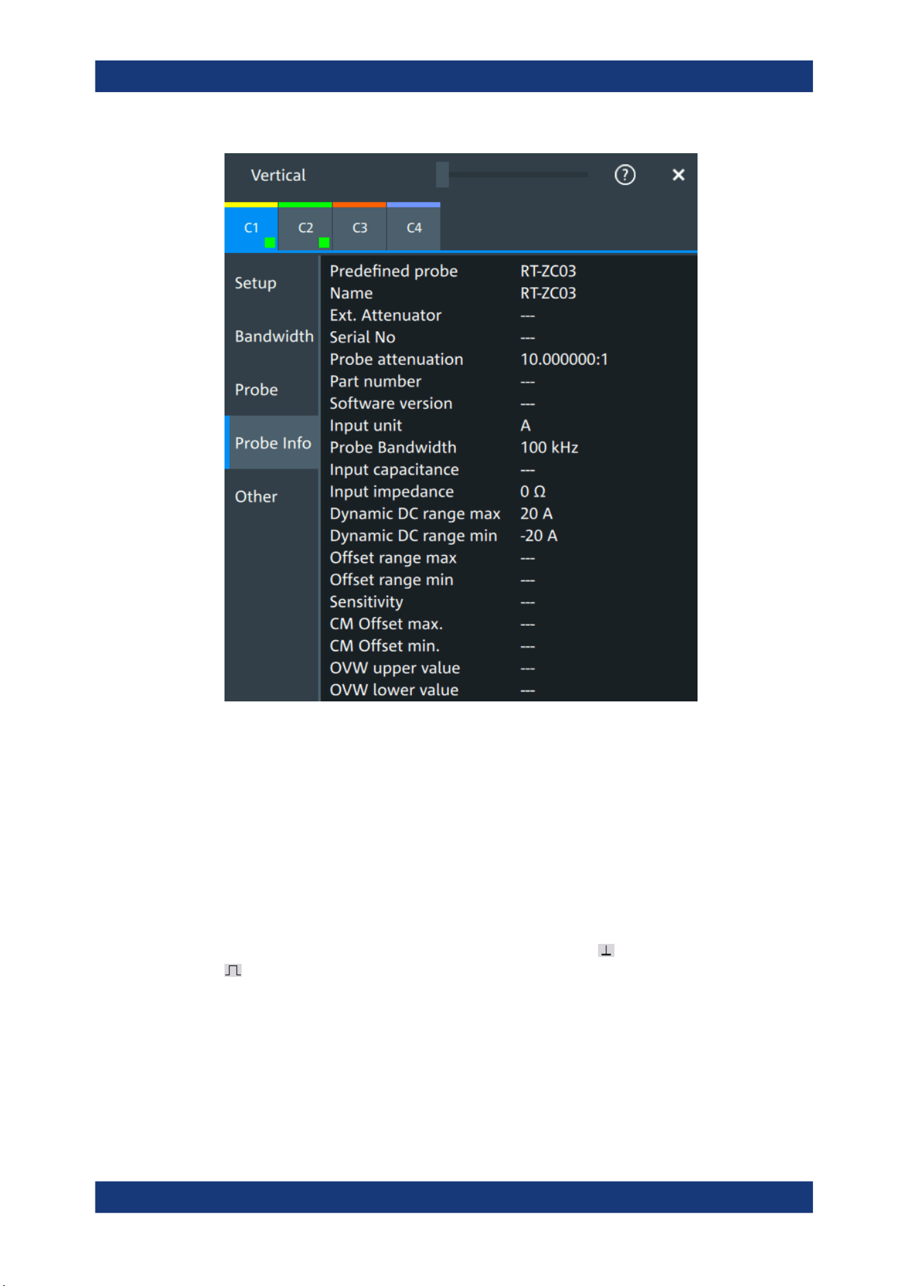
Acquisition and waveform setup
R&S
®
MXO 5 Series
132User Manual 1802.3369.02 ─ 02
Remote commands: Chapter 17.8.8.4, "Probe attributes", on page 489.
6.4.6 Adjusting passive probes
When using a passive probe, you have to compensate it when you connect it to the
instrument the first time. Compensation matches the probe cable capacitance to the
oscilloscope input capacitance to assure good amplitude accuracy from DC to upper
bandwidth limit frequencies. A poorly compensated probe reduces the performance of
the probe-oscilloscope system and introduces measurement errors resulting in distor-
ted waveforms and inaccurate results.
Two connector pins are located on the front panel. The pin is on ground level. The
pin supplies a square wave signal with 1 kHz for low frequency probe compensa-
tion.
1. Connect the BNC connector of the probe to one of the channel inputs.
2. Connect the probe's ground connector to the ground compensation pin, and the
probe tip to the signal pin.
3. Press [Autoset].
Probes

Acquisition and waveform setup
R&S
®
MXO 5 Series
133User Manual 1802.3369.02 ─ 02
A square wave appears on the display.
4. Adjust the compensation trimmer of the probe to optimum square wave response.
For details, refer to the documentation of your probe.
Probes

Trigger
R&S
®
MXO 5 Series
134User Manual 1802.3369.02 ─ 02
7 Trigger
● Basics of triggering................................................................................................134
● Common trigger settings.......................................................................................135
● Trigger types......................................................................................................... 137
● Trigger mode / holdoff........................................................................................... 152
● Hysteresis............................................................................................................. 155
● Channel filter.........................................................................................................156
● Actions on trigger.................................................................................................. 157
7.1 Basics of triggering
Triggering means to capture the interesting part of the relevant waveforms, and the
trigger point is the determining point in the waveform record. Choosing the right trigger
type and configuring all trigger settings correctly allows you to detect various incidents
in analog, digital, and protocol signals.
How the instrument triggers
A trigger occurs if the complete set of trigger conditions is fulfilled. The instrument
acquires continuously and keeps the sample points to fill the pre-trigger part of the
waveform record. When the trigger occurs, the instrument continues acquisition until
the post-trigger part of the waveform record is filled. Then it stops acquiring and waits
for the next trigger. When a trigger is recognized, the instrument does not accept
another trigger until the acquisition is complete and the holdoff time has expired.
Trigger setup
A simple trigger setup includes:
●
Source of the trigger signal
●
Trigger type selection and setup
●
Horizontal position of the trigger, see: Chapter 6.1.1, "About the horizontal system",
on page 100
●
Trigger mode
The R&S MXO 5 provides various trigger types for troubleshooting and signal analysis,
for example, edge trigger, glitch trigger, interval trigger, and much more.
For complex tasks like verifying and debugging designs, advanced trigger settings are
available:
●
Filter to remove high or low frequencies from the trigger signal
●
Hysteresis to avoid unwanted trigger events caused by noise
●
Holdoff to define exactly which trigger event causes the trigger
Action on trigger
A trigger can initiate a trigger out signal.
Basics of triggering
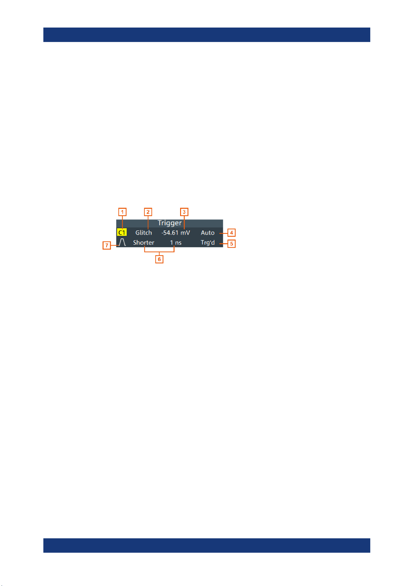
Trigger
R&S
®
MXO 5 Series
135User Manual 1802.3369.02 ─ 02
7.1.1 Trigger information
Information on the most important trigger settings is shown in the trigger label above
the diagram. If you tap the trigger label, the "Trigger" dialog opens.
If you trigger on a single event, the trigger label shows:
●
Trigger source
●
Trigger type
●
Trigger level
●
Trigger mode
●
Edge or polarity, and important trigger-type specific settings
●
Trigger state
Figure 7-1: Trigger label on the toolbar
1 = Trigger source
2 = Trigger type
3 = Trigger level
4 = Trigger mode
5 = Trigger state
6 = Trigger type specific settings
7 = Trigger slope
7.2 Common trigger settings
Access: "Menu" > "Trigger" > "Setup" tab
The common trigger settings are the trigger source and the trigger type, including the
trigger level. To set the trigger level automatically, use "Find level".
Common trigger settings
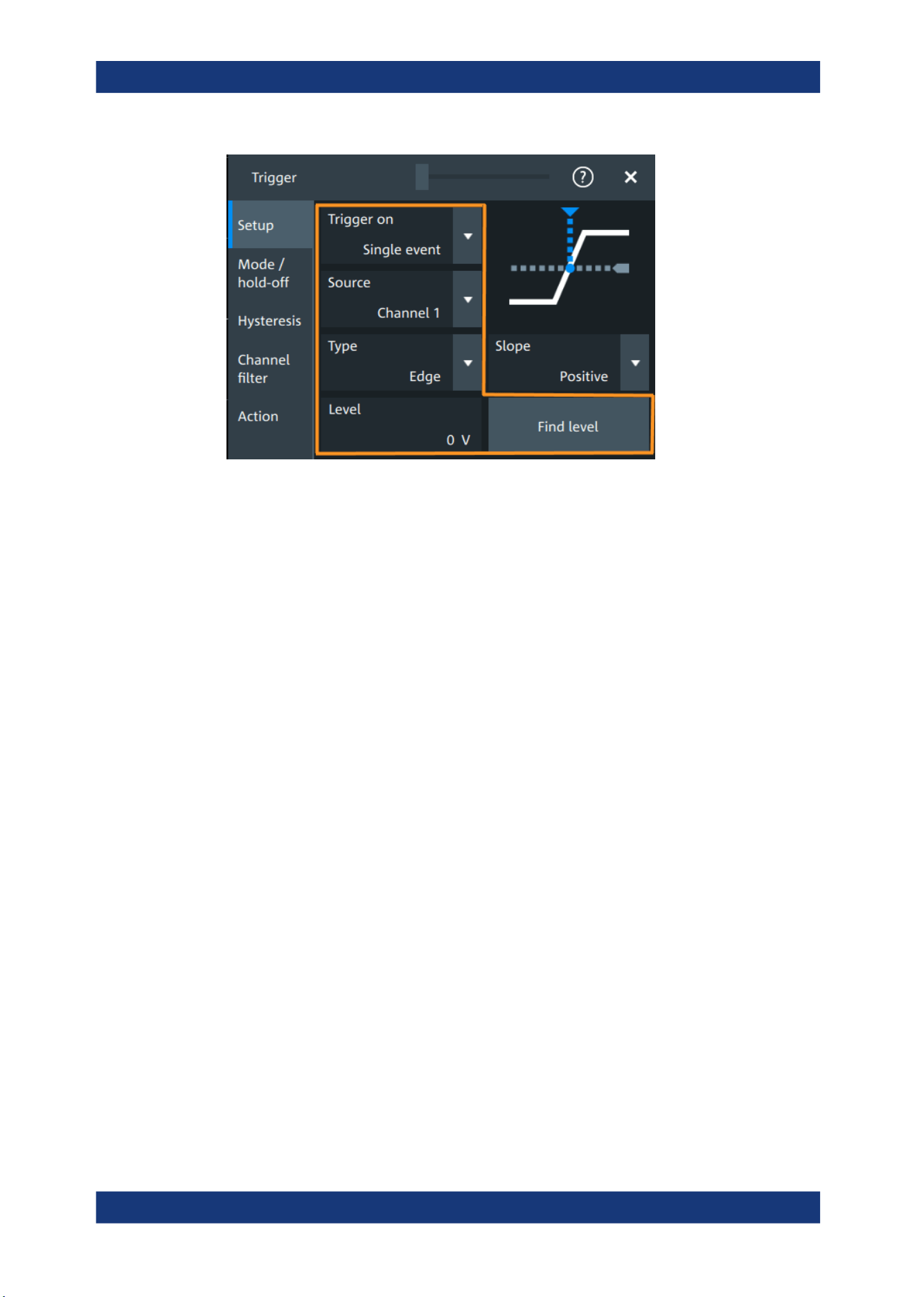
Trigger
R&S
®
MXO 5 Series
136User Manual 1802.3369.02 ─ 02
Depending on the trigger type, additional settings are available. They are explained in
the trigger-type specific sections.
Trigger on....................................................................................................................136
Source.........................................................................................................................136
Type............................................................................................................................ 136
Level............................................................................................................................137
Find level.....................................................................................................................137
Trigger on
Trigger on single event is the only supported mode.
Remote command:
TRIGger:MEVents:MODE on page 493
Source
Selects the source of the trigger signal for the selected trigger event. The trigger
source works even if it is not displayed in a diagram.
All inputs can be used as trigger source.
The trigger source can be:
●
Channel <n>: an analog input channel
●
Extern: external analog signal connected to the external trigger input. For the exter-
nal trigger source, the analog edge trigger is available.
●
Line: The instrument generates the trigger from the AC power input and synchroni-
zes the signal to the AC power frequency. Use this source if you want to analyze
signals related to the power line frequency, such as lighting equipment and power
supply devices. For the line trigger source, the edge trigger type is available.
●
Digital channels D0 to D15, serial bus
Remote command:
TRIGger:EVENt<ev>:SOURce on page 494
Type
Selects the trigger type.
Common trigger settings

Trigger
R&S
®
MXO 5 Series
137User Manual 1802.3369.02 ─ 02
The current trigger type is shown on the button and in the trigger label above the dia-
gram.
The following trigger types are available:
●
Edge trigger, see page 138
●
Glitch trigger, see page 140
●
Width trigger, see page 142
●
Runt trigger, see page 143
●
Window trigger, see page 145
●
Timeout trigger, see page 147
●
Interval trigger, see page 148
●
Slew rate trigger, see page 150
If the external trigger input is used as trigger source, the analog edge trigger is the only
available trigger type.
For digital channels, the edge, width and timeout trigger are available.
Remote command:
TRIGger:EVENt<ev>:TYPE on page 493
Level
Sets the voltage level or threshold for the trigger.
You can also drag the trigger level marker on the display, or turn the [Level] knob. To
set the trigger level to 50% of the signal amplitude, press the [Level] knob.
For the timeout trigger, the trigger level is the threshold for the high and low signal
states.
Runt, window and slew rate triggers require two trigger levels (upper and lower), which
are defined as specific settings.
Remote command:
TRIGger:EVENt<ev>:LEVel<n>[:VALue] on page 493
TRIGger:ANEDge:LEVel on page 495 (for external trigger source)
Find level
Sets the trigger level automatically to 0.5 * (MaxPeak – MinPeak).
The function is not available for trigger sources "Extern" and "Line".
Remote command:
TRIGger:FINDlevel on page 494
7.3 Trigger types
● Edge trigger...........................................................................................................138
● Edge trigger on external trigger source.................................................................138
● Glitch trigger..........................................................................................................140
● Width trigger..........................................................................................................142
● Runt trigger........................................................................................................... 143
● Window trigger...................................................................................................... 145
● Timeout trigger...................................................................................................... 147
Trigger types
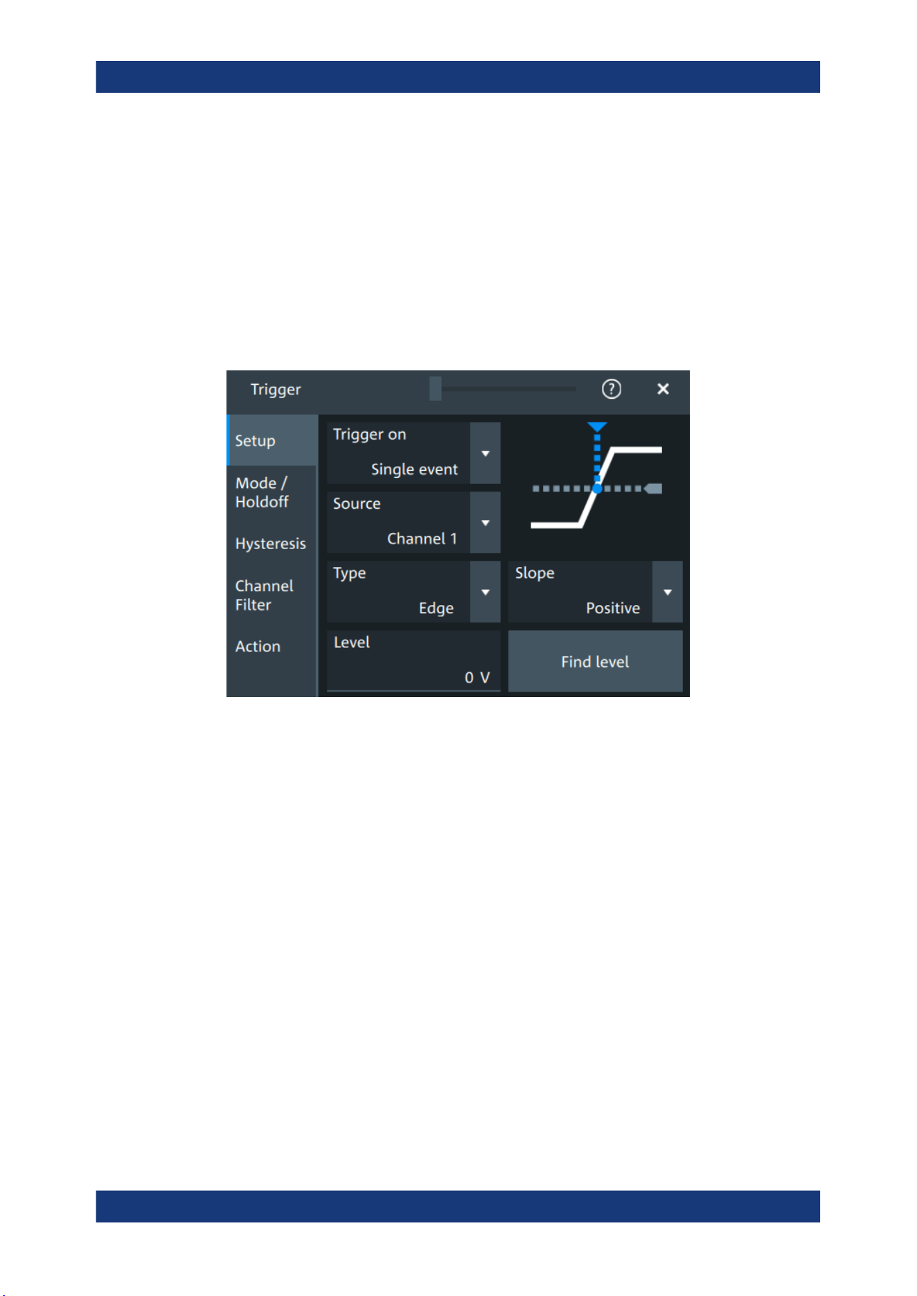
Trigger
R&S
®
MXO 5 Series
138User Manual 1802.3369.02 ─ 02
● Interval trigger....................................................................................................... 148
● Slew rate trigger....................................................................................................150
● Line trigger............................................................................................................ 152
7.3.1 Edge trigger
Access: "Menu" > "Trigger" > "Setup" tab > "Type = Edge"
The edge trigger is the most common trigger type. The trigger occurs when the signal
from the trigger source passes the trigger level in the specified direction (slope).
Level
See "Level" on page 137.
Remote command:
TRIGger:EVENt<ev>:LEVel<n>[:VALue] on page 493
Slope
Sets the edge direction for the trigger.
"Positive"
Selects the rising edge, which is a positive voltage change.
"Negative"
Selects the falling edge, which is a negative voltage change.
"Either"
Selects the rising and falling edge. After starting an acquisition, the
instrument triggers on the first identified edge.
Remote command:
TRIGger:EVENt<ev>:EDGE:SLOPe on page 494
7.3.2 Edge trigger on external trigger source
Access: "Menu" > "Trigger" > "Setup" tab > "Source" = "Extern" > "Type = Analog
Edge"
Trigger types
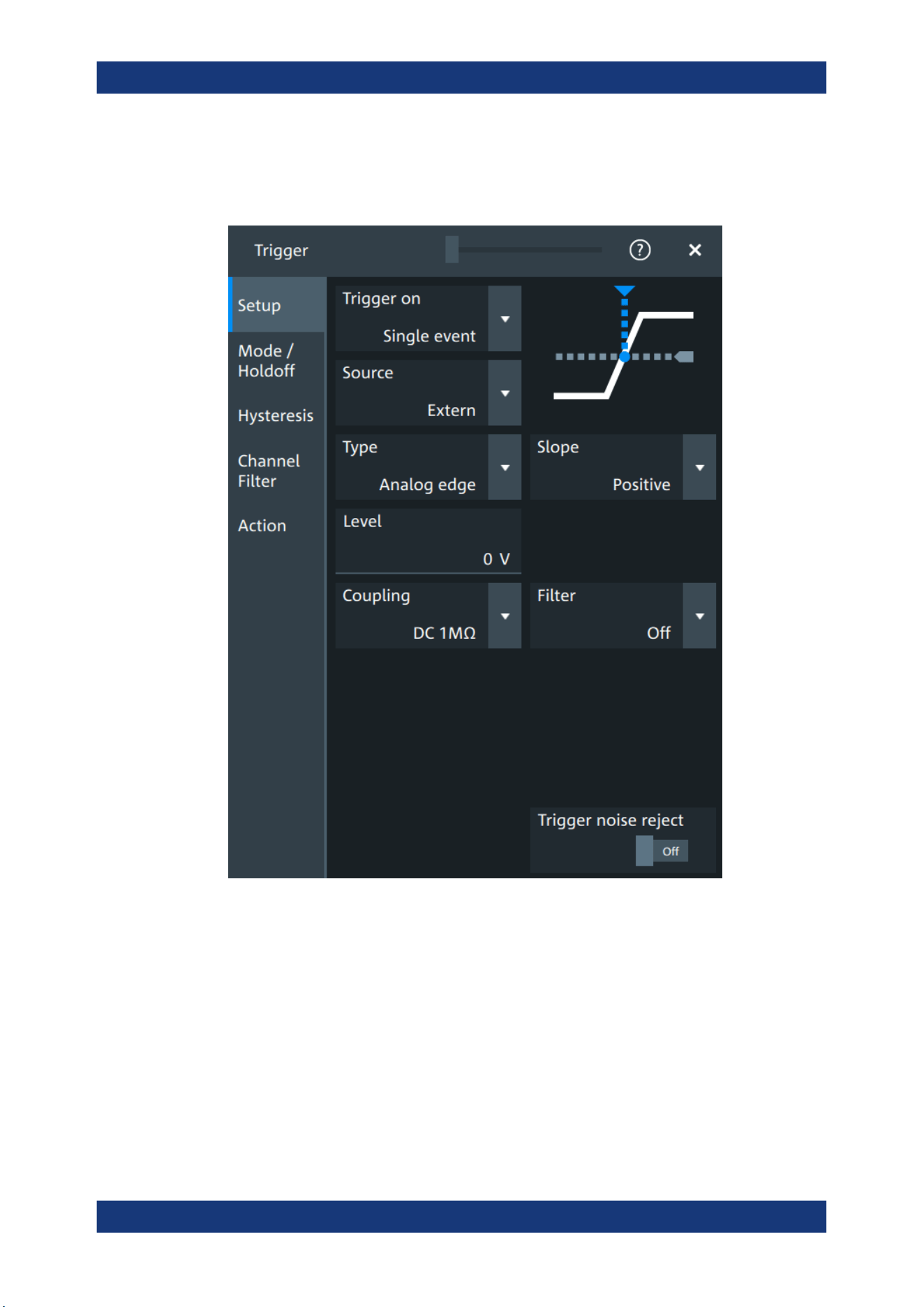
Trigger
R&S
®
MXO 5 Series
139User Manual 1802.3369.02 ─ 02
If an external trigger signal is connected to the Trigger In connector, and the trigger
source is set to "Extern", the analog edge trigger is available. Triggering on an external
source is only possible if you trigger on a single event but not for sequences.
The "Slope" and "Level" are the same settings as for the edge trigger, see:
●
"Level" on page 137
●
"Slope" on page 138
Specific settings for the analog edge trigger are the following:
Coupling
Sets the connection of the external trigger signal, i.e. the input impedance and a termi-
nation. The coupling determines what part of the signal is used for triggering.
"DC 50
Ω"
Connection with 50 Ω termination, passes both DC and AC compo-
nents of the signal.
Trigger types

Trigger
R&S
®
MXO 5 Series
140User Manual 1802.3369.02 ─ 02
"DC 1 MΩ"
Connection with 1 MΩ termination, passes both DC and AC compo-
nents of the signal.
"AC 1 MΩ"
Connection with 1 MΩ termination through DC capacitor, removes DC
and very low-frequency components. The waveform is centered on
zero volts.
Remote command:
TRIGger:ANEDge:COUPling on page 495
Filter, Cut-off
Selects the filter mode for the external trigger signal, and sets the cut-off frequency.
"Off"
The trigger signal is not filtered.
"LF reject"
Frequencies lower than the "Cut-off" frequency are rejected, higher
frequencies pass the filter.
"RF reject"
Frequencies higher than the "Cut-off" frequency are rejected, lower
frequencies pass the filter.
Remote command:
TRIGger:ANEDge:FILTer on page 495
TRIGger:ANEDge:CUToff:HIGHpass on page 496
TRIGger:ANEDge:CUToff:LOWPass on page 496
Trigger noise reject
Enables an automatic hysteresis on the trigger level to avoid unwanted trigger events
caused by noise.
Remote command:
TRIGger:ANEDge:NREJect on page 496
7.3.3 Glitch trigger
Access: "Menu" > "Trigger" > "Setup" tab > "Type = Glitch"
Trigger types
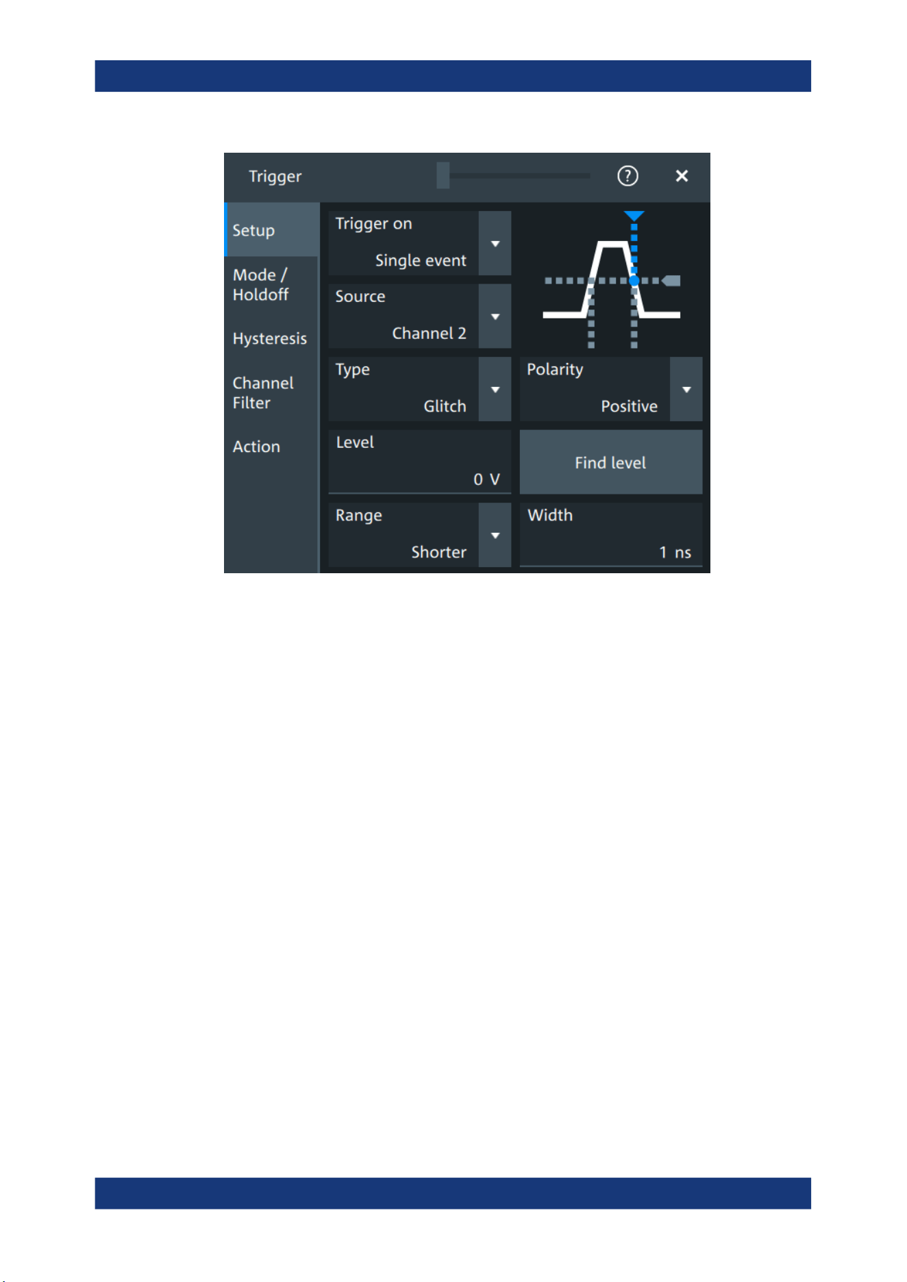
Trigger
R&S
®
MXO 5 Series
141User Manual 1802.3369.02 ─ 02
Level
See "Level" on page 137.
Remote command:
TRIGger:EVENt<ev>:LEVel<n>[:VALue] on page 493
Polarity
Sets the polarity of a pulse, which is the direction of the first pulse slope.
"Positive"
Selects positive going pulses, the width is defined from the rising to
the falling slopes.
"Negative"
Selects negative going pulses, the width is defined from the falling to
the rising slopes.
"Either"
Selects both positive and negative going pulses.
Remote command:
TRIGger:EVENt<ev>:GLITch:POLarity on page 497
TRIGger:EVENt<ev>:RUNT:POLarity on page 500
Range
Selects how the time limit of the runt pulse is defined.
Remote command:
TRIGger:EVENt<ev>:GLITch:RANGe on page 497
Width
Sets the length of a glitch. The instrument triggers on pulses shorter or longer than this
value, depending on the value set with "Range".
Trigger types
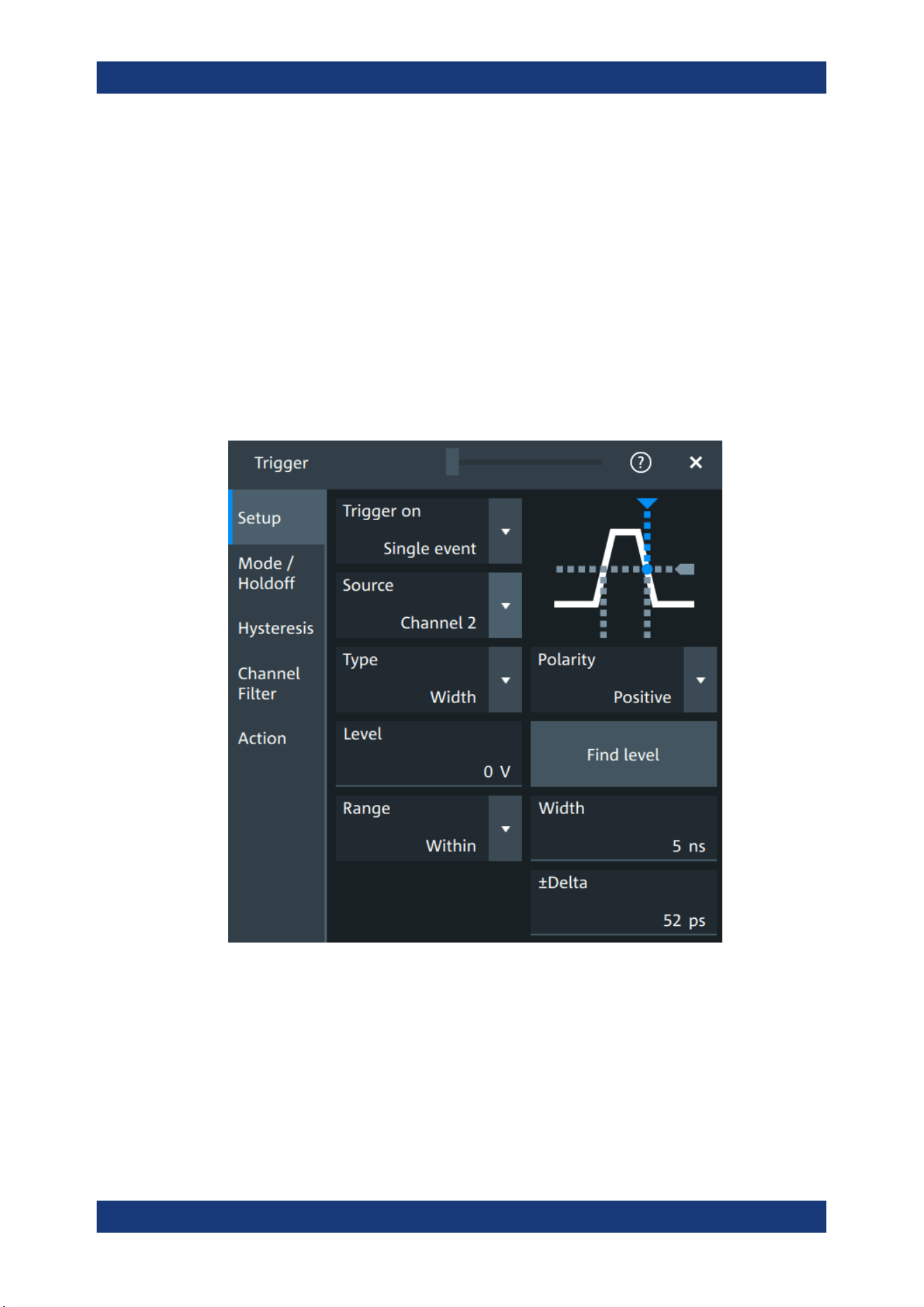
Trigger
R&S
®
MXO 5 Series
142User Manual 1802.3369.02 ─ 02
You need to know the expected pulse widths of the circuit to set the glitch width cor-
rectly.
Remote command:
TRIGger:EVENt<ev>:GLITch:WIDTh on page 497
7.3.4 Width trigger
Access: "Menu" > "Trigger" > "Setup" tab > "Type = Width"
The width trigger compares the pulse width (duration) with given time limits. It detects
pulses with an exact pulse width, pulses shorter or longer than a given time, and also
pulses inside or outside the allowable time range. The pulse width is measured at the
trigger level.
Level
See "Level" on page 137.
Remote command:
TRIGger:EVENt<ev>:LEVel<n>[:VALue] on page 493
Polarity
Sets the polarity of a pulse, which is the direction of the first pulse slope.
Trigger types

Trigger
R&S
®
MXO 5 Series
143User Manual 1802.3369.02 ─ 02
"Positive"
Selects positive going pulses, the width is defined from the rising to
the falling slopes.
"Negative"
Selects negative going pulses, the width is defined from the falling to
the rising slopes.
"Either"
Selects both positive and negative going pulses.
Remote command:
TRIGger:EVENt<ev>:WIDTh:POLarity on page 498
Range
Selects how the range of a pulse width is defined.
"Longer"
Triggers on pulses longer than the given "Width".
"Shorter"
Triggers on pulses shorter than the given "Width".
"Within"
Triggers on pulses inside a given range. The range of the pulse width
is defined by "±Delta" related to "Width".
"Outside"
Triggers on pulses outside a given range. The range definition is the
same as for "Within" range.
Remote command:
TRIGger:EVENt<ev>:WIDTh:RANGe on page 498
Width
For the ranges "Within" and "Outside", the width defines the center of a range which is
defined by the limits "±Delta".
For the ranges "Shorter" and "Longer", the width defines the maximum and minimum
pulse width, respectively.
Remote command:
TRIGger:EVENt<ev>:WIDTh:WIDTh on page 499
±Delta
Defines a range around the width value.
The combination "Range" = "Within" and "±Delta" = 0 triggers on pulses with a pulse
width that equals "Width".
The combination "Range" = "Outside" and "±Delta" = 0 means to trigger on pulse
widths ≠ "Width".
Remote command:
TRIGger:EVENt<ev>:WIDTh:DELTa on page 498
7.3.5 Runt trigger
Access: "Menu" > "Trigger" > "Setup" tab > "Type = Runt"
A runt is a pulse lower than normal in amplitude. The amplitude crosses the first
threshold twice in succession without crossing the second one. For example, this trig-
ger can detect logic, digital, and analog signals remaining below a specified threshold
amplitude because I/O ports are in undefined state.
Trigger types
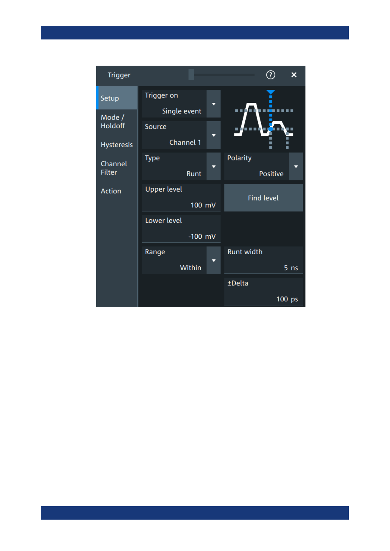
Trigger
R&S
®
MXO 5 Series
144User Manual 1802.3369.02 ─ 02
Polarity
Sets the polarity of a pulse, which is the direction of the first pulse slope.
"Positive"
Selects positive going pulses, the width is defined from the rising to
the falling slopes.
"Negative"
Selects negative going pulses, the width is defined from the falling to
the rising slopes.
"Either"
Selects both positive and negative going pulses.
Remote command:
TRIGger:EVENt<ev>:GLITch:POLarity on page 497
TRIGger:EVENt<ev>:RUNT:POLarity on page 500
Upper level
Sets the upper voltage limit.
Remote command:
TRIGger:EVENt<ev>:LEVel<n>:RUNT:UPPer on page 500
Lower level
Sets the lower voltage limit.
Trigger types

Trigger
R&S
®
MXO 5 Series
145User Manual 1802.3369.02 ─ 02
Remote command:
TRIGger:EVENt<ev>:LEVel<n>:RUNT:LOWer on page 499
Range
Selects how the time limit of the runt pulse is defined.
"Any runt"
Triggers on all runts fulfilling the level condition, without time limita-
tion.
"Longer"
Triggers on runts longer than the given "Runt width".
"Shorter"
Triggers on runts shorter than the given "Runt width".
"Within"
Triggers if the runt length is inside a given time range. The range is
defined by "Runt width" and "±Delta".
"Outside"
Triggers if the runt length is outside a given time range. The range
definition is the same as for "Within" range.
Remote command:
TRIGger:EVENt<ev>:RUNT:RANGe on page 501
Runt width
For the ranges "Shorter" and "Longer", the runt width defines the maximum and mini-
mum pulse width, respectively.
For the ranges "Within" and "Outside", the runt width defines the center of a range
which is defined by "±Delta".
Remote command:
TRIGger:EVENt<ev>:RUNT:WIDTh on page 501
±Delta
Defines a range around the runt width value.
Remote command:
TRIGger:EVENt<ev>:RUNT:DELTa on page 500
7.3.6 Window trigger
Access: "Menu" > "Trigger" > "Setup" tab > "Type = Window"
The window trigger checks the signal run in relation to a "window". The window is
formed by the upper and lower voltage levels. The trigger condition is fulfilled, if the
waveform enters or leaves the window, or if the waveform stays inside or outside for a
time longer or shorter than specified.
With the window trigger, you can display longer transient effects.
Trigger types
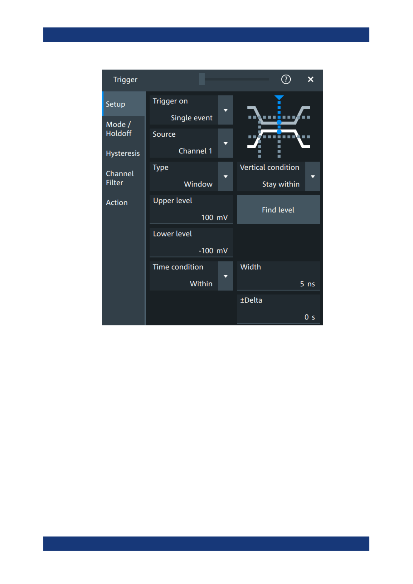
Trigger
R&S
®
MXO 5 Series
146User Manual 1802.3369.02 ─ 02
Vertical condition
Selects how the signal run is compared with the window.
"Enter"
Triggers when the signal crosses the upper or lower level and thus
enters the window made up of these two levels.
"Exit"
Triggers when the signal leaves the window.
"Stay within"
Triggers if the signal stays between the upper and lower level for a
specified time. The time is defined in various ways by the "Time con-
dition".
"Stay outside"
Triggers if the signal stays above the upper level or below the lower
level for a specified time. The time is also defined by the "Time condi-
tion".
Remote command:
TRIGger:EVENt<ev>:WINDow:RANGe on page 503
Upper level
Sets the upper voltage limit.
Remote command:
TRIGger:EVENt<ev>:LEVel<n>:WINDow:UPPer on page 502
Trigger types

Trigger
R&S
®
MXO 5 Series
147User Manual 1802.3369.02 ─ 02
Lower level
Sets the lower voltage limit.
Remote command:
TRIGger:EVENt<ev>:LEVel<n>:WINDow:LOWer on page 502
Time condition
Available for "Vertical condition" = "Stay within"/"Stay outside".
Selects how the time limit of the window is defined.
"Within"
Triggers if the signal stays inside or outside the vertical window limits
at least for the time Width - Delta and for Width + Delta at the most.
"Outside"
"Outside" is the opposite definition of "Within". The instrument triggers
if the signal stays inside or outside the vertical window limits for a
time shorter than Width - Delta or longer than Width + Delta.
"Shorter"
Triggers if the signal crosses vertical limits before the specified
"Width" time is reached.
"Longer"
Triggers if the signal crosses vertical limits after the specified "Width"
time is reached.
Remote command:
TRIGger:EVENt<ev>:WINDow:TIME on page 504
Width
For the ranges "Within" and "Outside", the width defines the center of a time range
which is defined by the limits "±Delta".
For the ranges "Shorter" and "Longer", it defines the maximum and minimum time
lapse, respectively.
Remote command:
TRIGger:EVENt<ev>:WINDow:WIDTh on page 504
±Delta
Defines a range around the width value.
Remote command:
TRIGger:EVENt<ev>:WINDow:DELTa on page 503
7.3.7 Timeout trigger
Access: "Menu" > "Trigger" > "Setup" tab > "Type = Timeout"
The timeout trigger checks if the signal stays above or below the threshold voltage for
a specified time lapse. In other words, the trigger occurs if the trigger source does not
have the expected transition within the specified time.
Trigger types
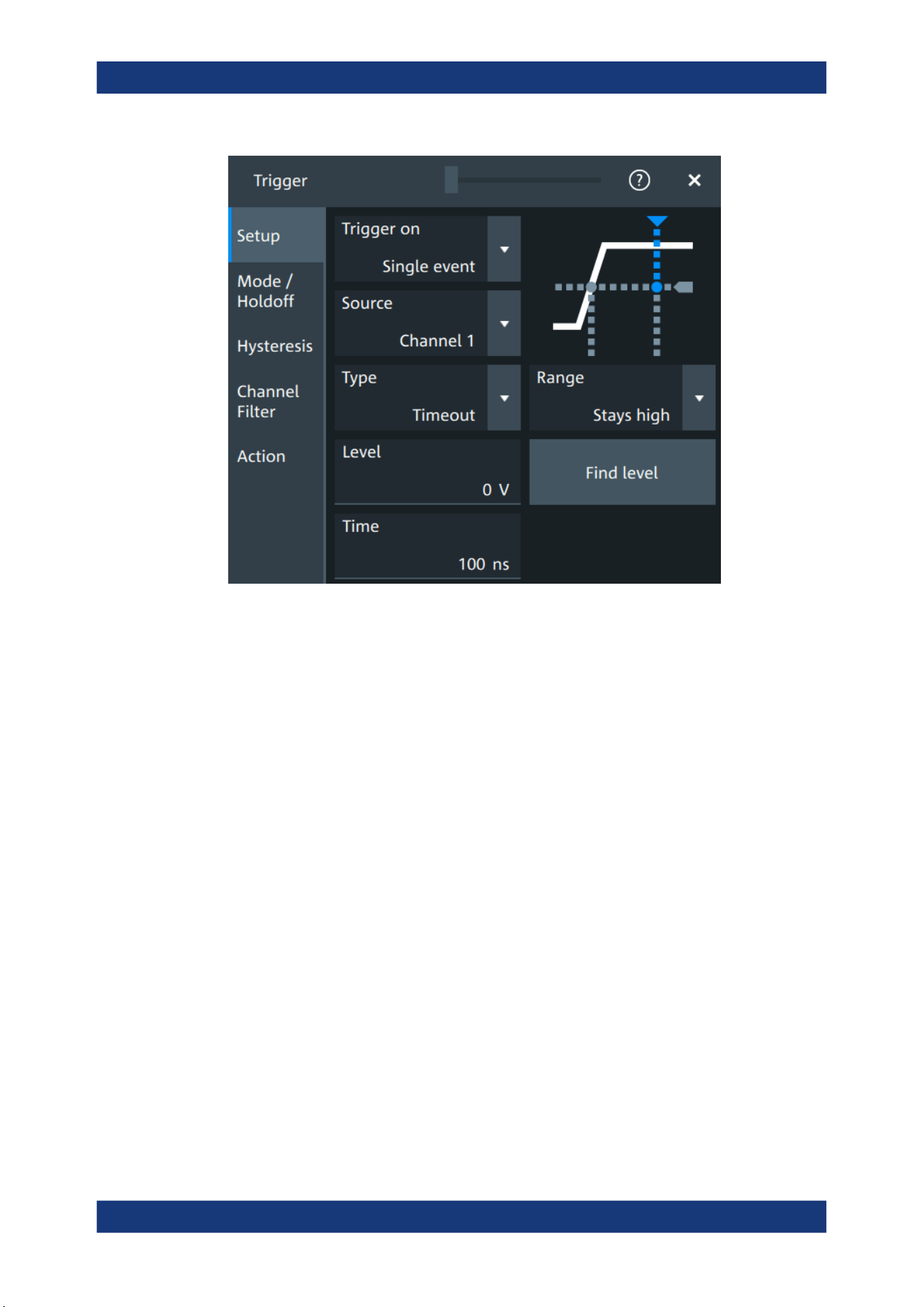
Trigger
R&S
®
MXO 5 Series
148User Manual 1802.3369.02 ─ 02
Level
Sets the threshold for the high and low signal states.
Remote command:
TRIGger:EVENt<ev>:LEVel<n>[:VALue] on page 493
Range
Sets the relation of the signal level to the trigger level for the timeout trigger.
"Stays high"
The signal level stays above the trigger level.
"Stays low"
The signal level stays below the trigger level.
"High or low"
The signal level stays above or below the trigger level.
Remote command:
TRIGger:EVENt<ev>:TIMeout:RANGe on page 505
Time
Sets the time limit for the timeout at which the instrument triggers.
Remote command:
TRIGger:EVENt<ev>:TIMeout:TIME on page 505
7.3.8 Interval trigger
Access: "Menu" > "Trigger" > "Setup" tab > "Type = Interval"
The interval trigger analyzes the time between two pulses.
Trigger types
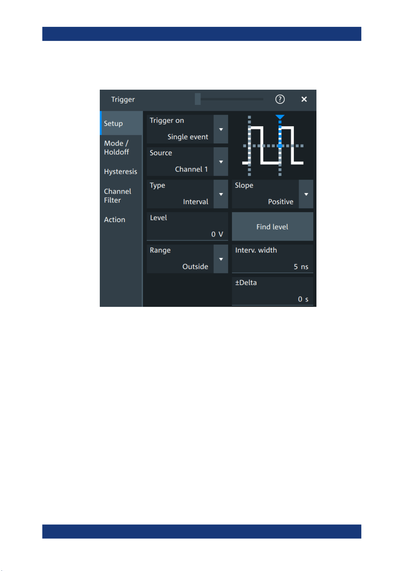
Trigger
R&S
®
MXO 5 Series
149User Manual 1802.3369.02 ─ 02
The interval trigger can analyze either rising or falling edges, but searching for an inter-
val is also possible for both edges at the same time ("Either").
Level
See "Level" on page 137.
Remote command:
TRIGger:EVENt<ev>:LEVel<n>[:VALue] on page 493
Slope
Sets the edge for the trigger. You can analyze the interval between positive edges or
between negative edges.
Remote command:
TRIGger:EVENt<ev>:INTerval:SLOPe on page 507
Range
Selects how the range of an interval is defined:
"Within"
Triggers on pulse intervals inside a given range. The range is defined
by "Interv. width" and "±Delta".
"Outside"
Triggers on intervals outside a given range. The range definition is
the same as for "Within" range.
"Shorter"
Triggers on intervals shorter than the given "Interv. width".
"Longer"
Triggers on intervals longer than the given "Interv. width".
Trigger types

Trigger
R&S
®
MXO 5 Series
150User Manual 1802.3369.02 ─ 02
Remote command:
TRIGger:EVENt<ev>:INTerval:RANGe on page 506
Interv. width
Sets the time between two pulses for the interval trigger.
Remote command:
TRIGger:EVENt<ev>:INTerval:WIDTh on page 507
±Delta
Defines a range around the "Interv. width" value.
Remote command:
TRIGger:EVENt<ev>:INTerval:DELTa on page 506
7.3.9 Slew rate trigger
Access: "Menu" > "Trigger" > "Setup" tab > "Type = Slew rate"
The slew rate trigger is also known as transition trigger. It triggers if the transition time
from the lower to higher voltage level (or vice versa) is shorter or longer as defined, or
outside or inside a specified time range.
The slew rate trigger finds slew rates faster than expected or permissible to avoid over-
shooting and other interfering effects. It also detects slow edges violating the timing in
pulse series.
Trigger types
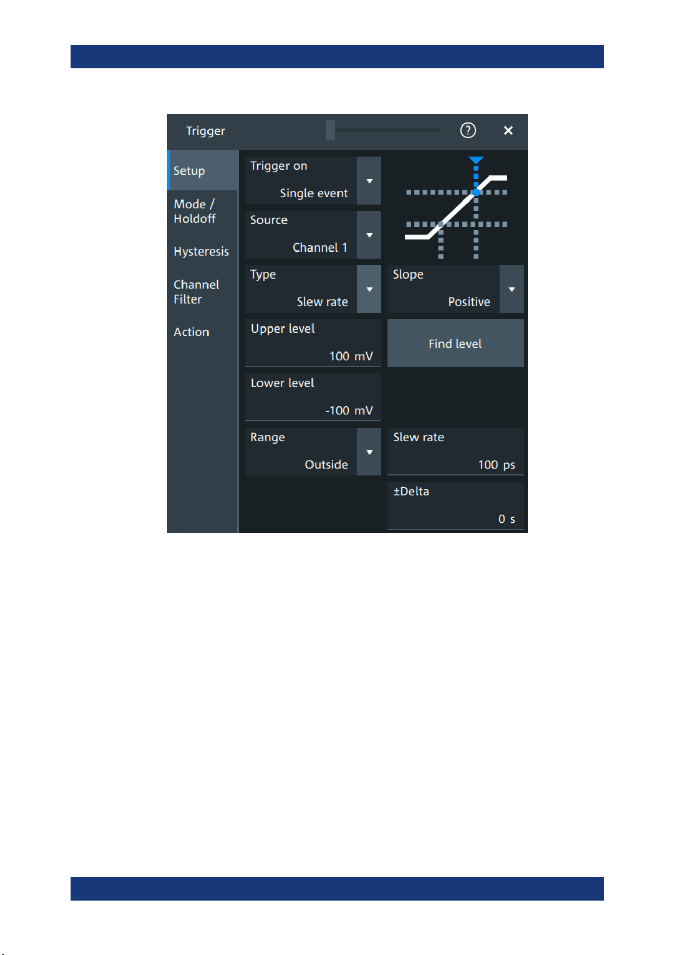
Trigger
R&S
®
MXO 5 Series
151User Manual 1802.3369.02 ─ 02
Slope
Sets the edge direction for the trigger.
"Positive"
Selects the rising edge, which is a positive voltage change.
"Negative"
Selects the falling edge, which is a negative voltage change.
"Either"
Selects the rising and falling edge. After starting an acquisition, the
instrument triggers on the first identified edge.
Remote command:
TRIGger:EVENt<ev>:SLEW:SLOPe on page 509
Upper level
Sets the upper voltage threshold. When the signal crosses this level, the slew rate
measurement starts or stops depending on the selected slope.
Remote command:
TRIGger:EVENt<ev>:LEVel<n>:SLEW:UPPer on page 508
Lower level
Sets the lower voltage threshold. When the signal crosses this level, the slew rate
measurement starts or stops depending on the selected slope.
Trigger types

Trigger
R&S
®
MXO 5 Series
152User Manual 1802.3369.02 ─ 02
Remote command:
TRIGger:EVENt<ev>:LEVel<n>:SLEW:LOWer on page 507
Range
Selects how the time limit for the slew rate is defined. The time measurement starts
when the signal crosses the first trigger level - the upper or lower limit depending on
the selected slope. The measurement stops when the signal crosses the second level.
"Within"
Triggers on slew rates inside a given time range. The range is defined
by "Slew rate" and "±Delta".
"Outside"
Triggers on slew rates outside a given time range. The range defini-
tion is the same as for "Within" range.
"Shorter"
Triggers on slew rates shorter than the given "Slew rate" limit.
"Longer"
Triggers on slew rates longer than the given "Slew rate" limit.
Remote command:
TRIGger:EVENt<ev>:SLEW:RANGe on page 508
Slew rate
For the ranges "Within" and "Outside", the slew rate defines the center of a range
which is defined by the limits "±Delta".
For the ranges "Shorter" and "Longer", the slew rate defines the maximum and mini-
mum slew rate limits, respectively.
Remote command:
TRIGger:EVENt<ev>:SLEW:RATE on page 509
±Delta
Defines a time range around the given slew rate.
Remote command:
TRIGger:EVENt<ev>:SLEW:DELTa on page 508
7.3.10 Line trigger
Access: "Menu" > "Trigger" > "Setup" tab > "Source" = "Line"
The line trigger is an edge trigger that triggers on the AC power input and synchronizes
the signal to the AC power frequency. It is not a trigger type but rather a special trigger
source. Use the line source if you want to analyze signals related to the power line fre-
quency, such as lighting equipment and power supply devices.
Slope
Selects the rising or falling edges of the AC power input.
7.4 Trigger mode / holdoff
Access: "Trigger" menu > "Mode / holdoff" tab
Trigger mode / holdoff
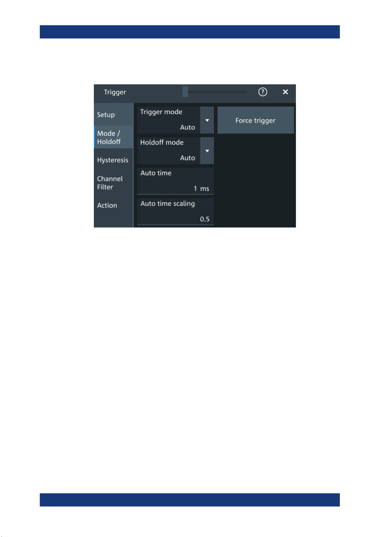
Trigger
R&S
®
MXO 5 Series
153User Manual 1802.3369.02 ─ 02
Holdoff conditions define a waiting time after the current trigger until the next trigger
can be recognized.
Trigger mode
Sets the trigger mode which determines the behavior of the instrument if no trigger
occurs. The current setting is shown on the trigger label.
To toggle quickly between "Auto" and "Normal" mode, use the [Auto Norm] key on the
front panel (in "Trigger" section).
"Auto"
The instrument triggers repeatedly after a time interval if the trigger
conditions are not fulfilled. If a real trigger occurs, it takes prece-
dence. This mode helps to see the waveform even before the trigger
conditions are set correctly. The waveform on the screen is not
synchronized, and successive waveforms are not triggered at the
same point of the waveform. The time interval depends on the time
base settings.
"Normal"
The instrument acquires a waveform only if a trigger occurs, that is, if
all trigger conditions are fulfilled. If no trigger occurs, no waveform is
acquired and the last acquired waveform is displayed. If no waveform
was captured before, none is displayed.
When no trigger has been found for longer than one second, a mes-
sage box appears that shows the time elapsed since the last trigger.
"Free run"
The instrument starts acquisition immediately and triggers after a
short time interval independent of the time base settings and faster
than in "Auto" mode. Real triggers are ignored. Use this mode if the
"Auto" mode is too slow.
Remote command:
TRIGger:MODE on page 510
Trigger mode / holdoff

Trigger
R&S
®
MXO 5 Series
154User Manual 1802.3369.02 ─ 02
Force trigger
Provokes an immediate single acquisition. Force the trigger if the acquisition is running
in normal mode and no valid trigger occurs. Thus, you can confirm that a signal is
available and use the waveform display to determine how to trigger on it.
Remote command:
TRIGger:FORCe on page 510
Holdoff mode
Selects the method to define the holdoff condition.
The trigger holdoff defines when the next trigger after the current will be recognized.
Thus, it affects the next trigger to occur after the current one. Holdoff helps to obtain
stable triggering when the oscilloscope is triggering on undesired events.
Holdoff settings are not available if the trigger source is an external trigger input or
serial bus, and if you trigger on a sequence of events.
Example:
For example, you want to analyze the first pulse in a burst of several pulses. At first,
you select a sufficiently slow time base to display the entire burst. Then, you set the
holdoff time a little longer than the length of the burst. Now, each trigger corresponds to
the first pulse in successive bursts, and you can change the time base to display the
waveform in more detail.
The following methods are available:
"Time"
Defines the holdoff directly as a time period. The next trigger occurs
only after the "Holdoff time" has passed.
"Events"
Defines the holdoff as a number of trigger events. The next trigger
only occurs when this number of events is reached. The number of
triggers to be skipped is defined in "Holdoff events".
"Random"
Defines the holdoff as a random time limited by "Minimum time" and
"Maximum time". For each acquisition cycle, the instrument selects a
new random holdoff time from the specified range.
Random holdoff prevents synchronization to discover effects invisible
with synchronized triggering, for example, the features of a pulse
train.
"Auto"
The holdoff time is calculated automatically based on the current hori-
zontal scale.
"Auto time scaling" defines the factor that the horizontal scale is multi-
plied with.
"Auto time" shows the resulting holdoff time: Auto time = Auto time
scaling * Horizontal scale.
"Off"
No holdoff
Remote command:
TRIGger:HOLDoff:MODE on page 511
TRIGger:HOLDoff:TIME on page 513
TRIGger:HOLDoff:EVENts on page 512
TRIGger:HOLDoff:MAX on page 512
Trigger mode / holdoff
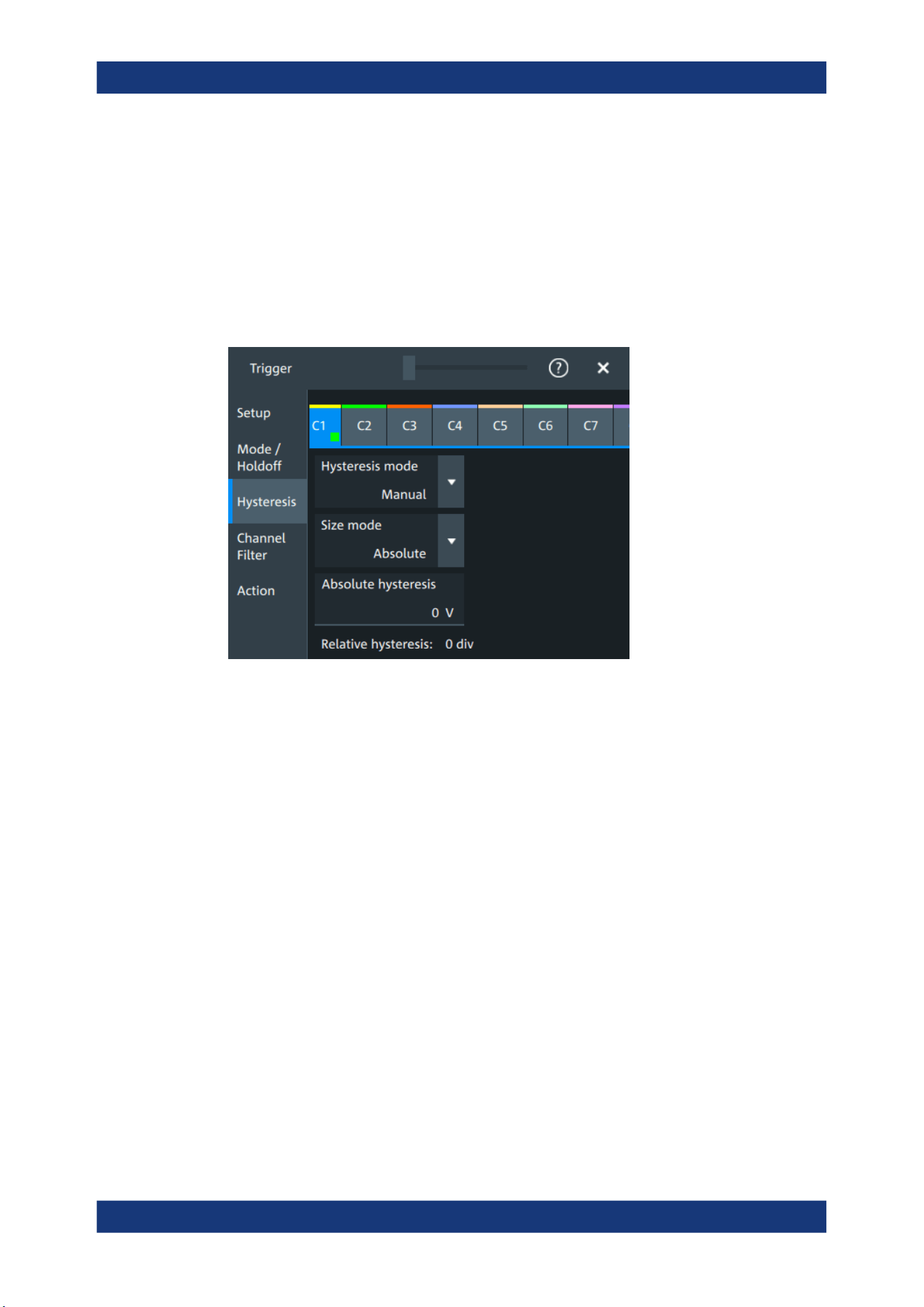
Trigger
R&S
®
MXO 5 Series
155User Manual 1802.3369.02 ─ 02
TRIGger:HOLDoff:MIN on page 513
TRIGger:HOLDoff:AUTotime? on page 511
TRIGger:HOLDoff:SCALing on page 512
7.5 Hysteresis
Access: "Menu">"Trigger" > "Hysteresis"
The rejection of noise by setting a hysteresis avoids unwanted trigger events caused
by noise oscillation around the trigger level.
HW hysteresis
Displays the hysteresis that is set by the instrument in automatic hysteresis mode.
Remote command:
TRIGger:NOISe<m>:EFFective? on page 514
Hysteresis mode
Selects how the hysteresis is set.
"Auto"
Automatic mode is the recommended mode. The hysteresis is set by
the instrument to reject the internal noise of the instrument.
"Manual"
The hysteresis is defined directly in absolute or relative values.
Remote command:
TRIGger:NOISe<m>:MODE on page 514
Size mode
Selects whether the hysteresis is defined in absolute or relative values. The setting is
available only in manual hysteresis mode.
Remote command:
TRIGger:NOISe<m>:MODE on page 514
Hysteresis
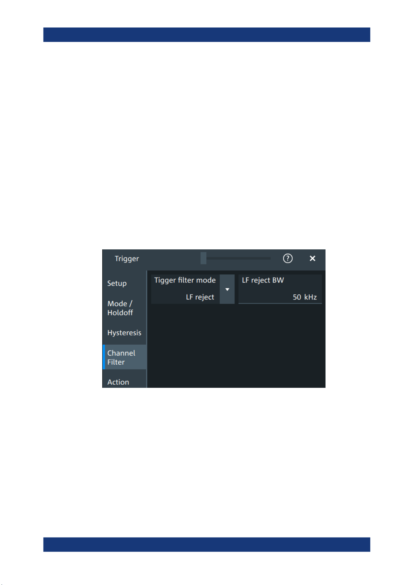
Trigger
R&S
®
MXO 5 Series
156User Manual 1802.3369.02 ─ 02
Absolute hysteresis
Defines a range in absolute values around the trigger level. If the signal oscillates
inside this range and thus crosses the trigger level, no trigger event occurs.
Remote command:
TRIGger:NOISe<m>:ABSolute on page 513
Relative hysteresis
Defines a range in divisions around the trigger level in division or as percentage. If the
signal oscillates inside this range and thus crosses the trigger level, no trigger event
occurs.
Remote command:
TRIGger:NOISe<m>:PERDivision on page 514
TRIGger:NOISe<m>:RELative on page 515
7.6 Channel filter
Access: "Menu">"Trigger" > "Channel filter"
Trigger filter mode
Selects the filter mode for the trigger channel.
"Off"
The trigger signal is not filtered.
"LF reject"
Frequencies lower than the "LF reject BW" are rejected, higher fre-
quencies pass the filter.
"RF reject"
Frequencies higher than the "RF reject BW" are rejected, lower fre-
quencies pass the filter.
Remote command:
TRIGger:FILTermode on page 515
Channel filter
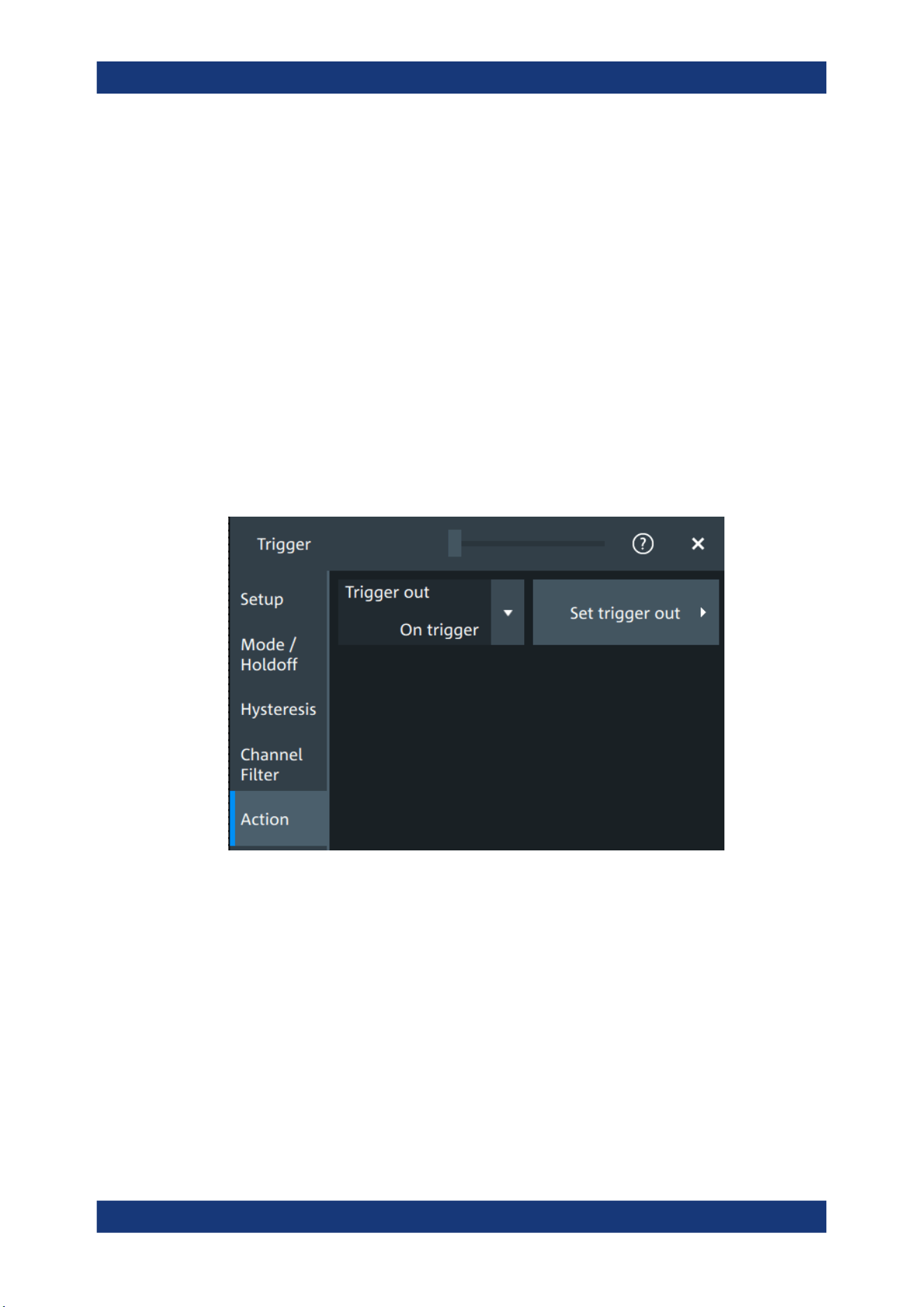
Trigger
R&S
®
MXO 5 Series
157User Manual 1802.3369.02 ─ 02
LF reject BW
Sets the limit frequency limit for the highpass filter of the trigger signal. Frequencies
lower than this value are rejected, higher frequencies pass the filter.
Remote command:
TRIGger:LFReject on page 516
RF reject BW
Sets the limit frequency limit for the lowpass filter of the trigger signal. Frequencies
higher than this value are rejected, lower frequencies pass the filter.
Remote command:
TRIGger:RFReject on page 516
7.7 Actions on trigger
Access: "Menu" > "Trigger" > "Action" tab
The action settings define what happens when a trigger occurs. All available actions
can be initiated at the same time.
Trigger out
Selects, if a pulse is provided to the [Trigger Out] connector on the rear panel. The trig-
ger-out signal is used to synchronize the measurements of other instruments.
To adjust the outgoing signal, tap "Set trigger out".
Remote command:
TRIGger:ACTions:OUT:STATe on page 516
Set trigger out
Opens a dialog to adjust the trigger out pulse.
Actions on trigger
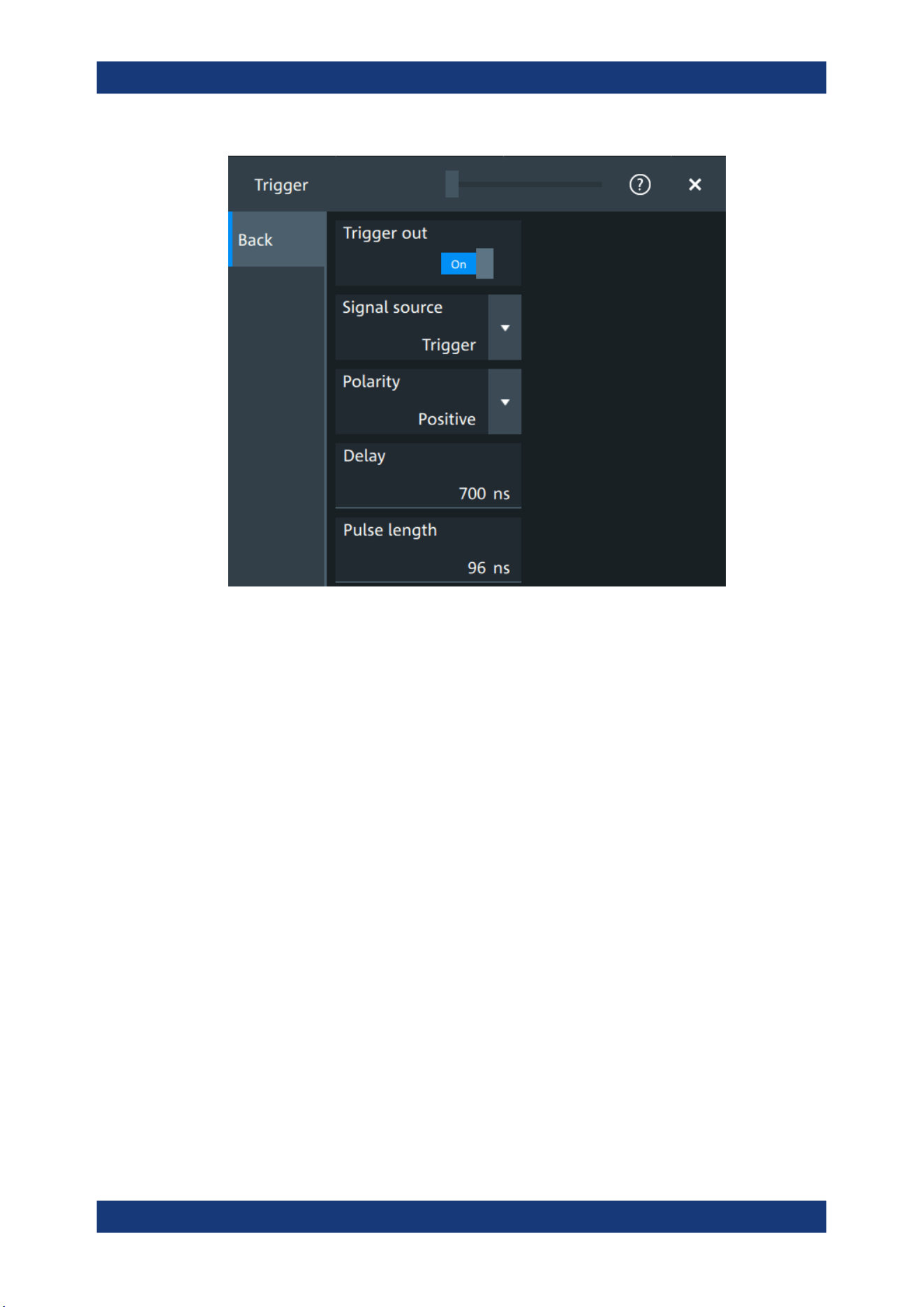
Trigger
R&S
®
MXO 5 Series
158User Manual 1802.3369.02 ─ 02
Trigger out ← Set trigger out
Activates the outgoing pulse on the [Trigger Out] connector on the rear panel.
Remote command:
TRIGger:ACTions:OUT:STATe on page 516
Signal source ← Set trigger out
Defines when the trigger out signal is initiated: at the trigger point, when waiting for the
trigger, or when the post-trigger time is finished.
Remote command:
TRIGger:ACTions:OUT:SOURce on page 517
Polarity ← Set trigger out
Sets the polarity of the trigger out pulse, which is the direction of the first pulse edge.
Remote command:
TRIGger:ACTions:OUT:POLarity on page 517
Delay ← Set trigger out
Defines the delay of the first pulse edge to the trigger point. The minimum delay is
600 ns.
Remote command:
TRIGger:ACTions:OUT:DELay on page 517
Pulse length ← Set trigger out
Sets the length of the trigger out pulse.
Actions on trigger


Waveform analysis
R&S
®
MXO 5 Series
160User Manual 1802.3369.02 ─ 02
8 Waveform analysis
This chapter describes general methods to check and analyze waveforms. These are:
● Zoom.....................................................................................................................160
● Mathematics..........................................................................................................164
● History...................................................................................................................170
● Reference waveforms........................................................................................... 176
8.1 Zoom
The zoom magnifies a part of the waveform to view more details. The zoom is applied
to all waveforms that are visible in a diagram.
For each diagram, you can define one zoom area.
●
You can define the zoom by drawing, moving and adjusting the zoom area on the
touchscreen.
●
You can precisely define the size of the zoom area by entering start and stop val-
ues in a dialog box.
Zoom areas can be used for gating, for example, to define a measurement gate. You
can set the gate exactly to the limits of the zoom.
8.1.1 Zoom settings
Access: "Menu" > "Horizontal" > "Zoom" tab.
The "Zoom" tab allows you to specify start and stop values for the x- and y-axes. The
acquired data within these ranges is zoomed.
Zoom
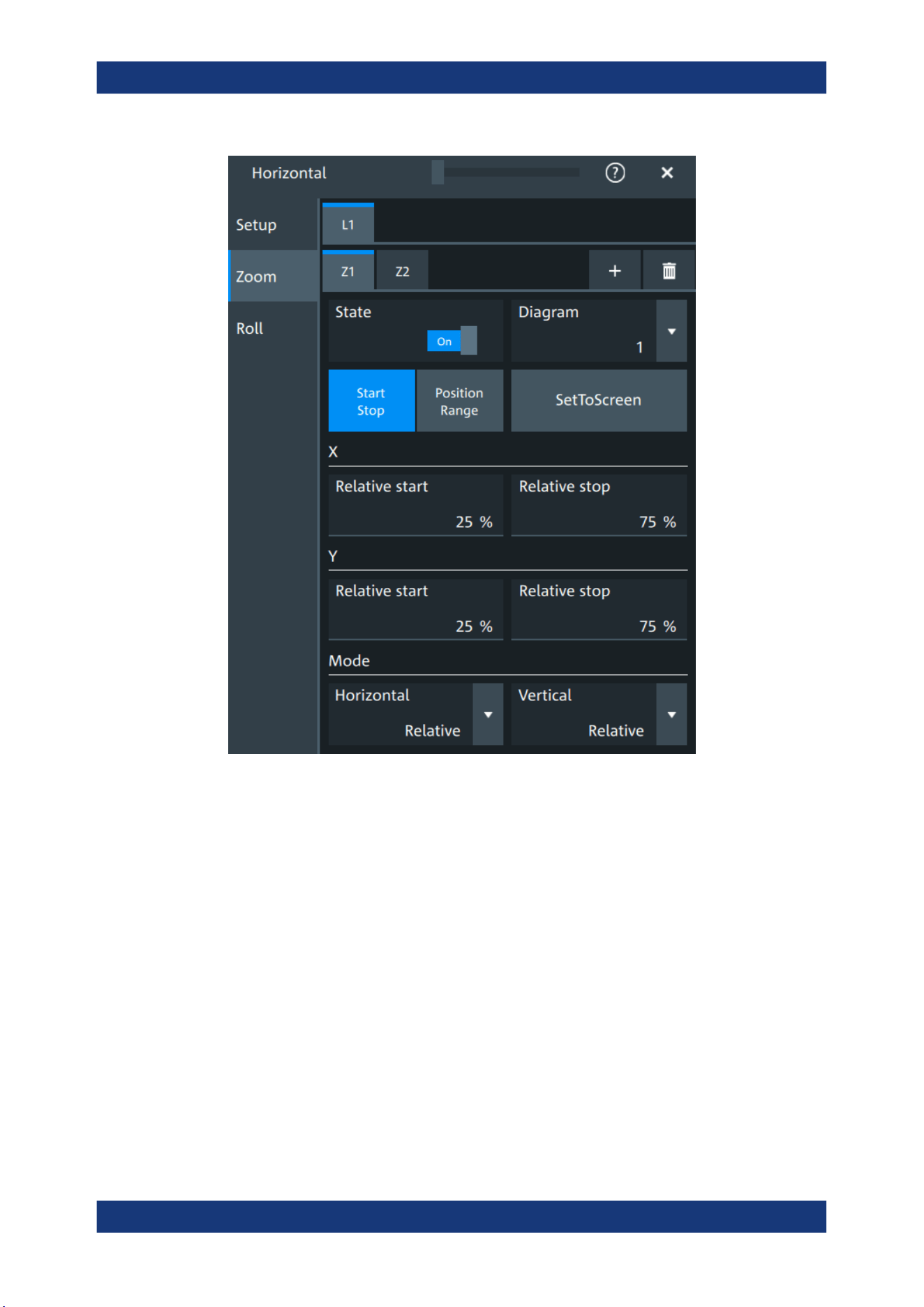
Waveform analysis
R&S
®
MXO 5 Series
161User Manual 1802.3369.02 ─ 02
Tabx
Selects one of the enabled SmartGrid layouts.
Zx
Selects the zoom window. You can add up to 8 different zooms.
State
Enables the zoom.
Remote command:
LAYout<ly>:ZOOM<zo>[:ENABle] on page 519
Diagram
Indicates which of the waveform diagrams is selected for zooming. The number is dis-
played on the screen in the middle of each diagram.
Remote command:
LAYout<ly>:ZOOM<zo>:SOURce on page 523
Zoom

Waveform analysis
R&S
®
MXO 5 Series
162User Manual 1802.3369.02 ─ 02
Start Stop, Position range
Selects how the window for the zoom diagram is defined. You can select between
defining "Start Stop" values or "Position range".
Start Stop
The "Start Stop" tab allows you to specify start and stop values for the x- and y-axes.
The acquired data within these ranges is zoomed.
According to the selected "Mode", absolute or relative values are used.
"Start", "Relative start"
Defines the lower limit of the zoom area on the axis.
"Stop", "Relative stop"
Defines the upper limit of the zoom area on the axis.
Remote command:
LAYout<ly>:ZOOM<zo>:HORizontal:ABSolute:STARt on page 520
LAYout<ly>:ZOOM<zo>:HORizontal:RELative:STARt on page 522
LAYout<ly>:ZOOM<zo>:HORizontal:ABSolute:STOP on page 520
LAYout<ly>:ZOOM<zo>:HORizontal:RELative:STOP on page 522
LAYout<ly>:ZOOM<zo>:VERTical:RELative:STARt on page 525
LAYout<ly>:ZOOM<zo>:VERTical:ABSolute:STARt on page 524
LAYout<ly>:ZOOM<zo>:VERTical:RELative:STOP on page 526
LAYout<ly>:ZOOM<zo>:VERTical:ABSolute:STOP on page 524
Position range
If "Position range" is selected, you specify the x and y position of center point of the
zoom area plus a range for the x- and y-axes. The area defined by that point and the
ranges is zoomed. You can set absolute values or relative values (in percent of the
screen, depending on the "Mode" selection.
"Range"
Defines the width or height of the zoom area.
"Position"
Defines the x or y value of the centerpoint of the zoom area.
Remote command:
LAYout<ly>:ZOOM<zo>:HORizontal:ABSolute:POSition on page 519
LAYout<ly>:ZOOM<zo>:HORizontal:RELative:POSition on page 521
LAYout<ly>:ZOOM<zo>:HORizontal:ABSolute:SPAN on page 520
LAYout<ly>:ZOOM<zo>:HORizontal:RELative:SPAN on page 522
LAYout<ly>:ZOOM<zo>:VERTical:ABSolute:POSition on page 523
LAYout<ly>:ZOOM<zo>:VERTical:RELative:POSition on page 525
LAYout<ly>:ZOOM<zo>:VERTical:ABSolute:SPAN on page 524
LAYout<ly>:ZOOM<zo>:VERTical:RELative:SPAN on page 526
Set to screen
Sets the zoom area to the whole screen.
Mode
Defines if absolute or relative values are used to specify the "Horizontal" (x-axis) and
the "Vertical" (y-axis) values.
Zoom

Waveform analysis
R&S
®
MXO 5 Series
163User Manual 1802.3369.02 ─ 02
Remote command:
LAYout<ly>:ZOOM<zo>:HORizontal:MODE on page 521
LAYout<ly>:ZOOM<zo>:VERTical:MODE on page 525
8.1.2 Zooming for details
To define the zoom area on the touchscreen
For graphical zooming, you use your finger on the screen.
1. On the toolbar, tap the "Add zoom" icon.
The zoom overlay menu opens.
2. Draw a rectangle in the diagram that defines the zoomed area.
While you drag your finger on the touchscreen, a dotted rectangle indicates the
current zoom area.
The indicated area is magnified in a new zoom diagram. The original diagram
shows the zoom area as a rectangle.
3. If the position of the zoom area is not correct, drag the rectangle in the overview to
the correct position.
4. If the size of the zoom area is not yet ideal, tap the rectangle in the overview dia-
gram.
Now, 4 white lines indicate the edges of the zoom area. A dashed white line indi-
cates the selected edge, which you can adjust.
5. Touch the edge that you want to move. Drag it to the required position.
To create a zoom using the zoom dialog box
► If you want to create a new, unconfigured zoom, tap the "Add" icon.
To define the zoom area numerically using start/stop values
1. Open "Menu" > "Horizontal".
2. In the "Zoom" tab, select "Start Stop".
3. Select a value for "Mode" > "Horizontal" to define "Absolute" or "Relative" x-axis
values. Relative values cause the zoom area to adapt to the input values dynami-
cally.
Zoom

Waveform analysis
R&S
®
MXO 5 Series
164User Manual 1802.3369.02 ─ 02
4. For "X", define the "Relative start" and "Relative stop" values. They define the
lower and upper borders of the zoom area on the x-axis.
5. Select the "Mode" > "Vertical" to define "Absolute" or "Relative" y-axis values.
6. For "Y", define the "Relative start" and "Relative stop" values. They define the
lower and upper borders of the zoom area on the y-axis.
When you close the dialog box, the specified area is magnified in a new zoom dia-
gram. The original diagram is displayed with the zoom area indicated as a rectan-
gle.
To define the zoom area numerically using position and range values
1. Open "Menu" > "Horizontal".
2. In the "Zoom" tab, select "Position range".
3. Select "Mode" > "Horizontal" to define "Absolute" or "Relative" x-axis values. Rela-
tive values cause the zoom area to adapt to the input values dynamically.
4. Under "X" > "Position", define the x-value of the center point of the zoom area.
5. Under "X" > "Range", define the width of the zoom area.
6. Select the "Mode" > "Vertical" to define "Absolute" or "Relative" y-axis values.
7. Under "Y" >"Position", define the y-value of the center point of the zoom area.
8. Under "Y" > "Range", define the height of the zoom area.
When you close the dialog box, the specified area is magnified in a new zoom dia-
gram. The original diagram is displayed with the zoom area indicated as a rectan-
gle.
8.2 Mathematics
Math waveforms are calculated waveforms. You can define up to 8 math waveforms
and display them on the screen, and use it as source for further analysis.
It is calculated out of one or two analog channels, or another math waveform using
several predefined operations. You can define up to 5 equations. The complete config-
uration is called equation set and can be saved for later use.
You can analyze math waveforms in the same way as channel waveforms: use zoom,
perform automatic and cursor measurements, and save as reference waveform.
You can store a math waveform as a reference waveform and restore it later.
Mathematics

Waveform analysis
R&S
®
MXO 5 Series
165User Manual 1802.3369.02 ─ 02
8.2.1 Displaying math waveforms
Math waveforms can be displayed in addition to the channel and other waveforms.
They also can be used for analysis, e.g. measurements, even if the math waveform is
not active.
1. Open "Menu" > "Math" >"Setup".
Alternatively, press the [Math] key.
2. Select the math "Operator".
3. If necessary, define the settings for the operator.
4. Tap "Display".
The math waveform is displayed on the screen. Also a green dot appears in the
enabled math tab.
5. To change the vertical scaling of the math waveform, open the "Scale" tab.
6. Set the "Scale mode" to "Manual".
7. Enter the "Vertical scale" factor (per division). If necessary, add a "Vertical offset".
By default the instrument performs an automatic scaling.
8. Close the "Math" dialog box.
8.2.2 Math waveforms settings
Access: [Math] > "Setup" tab
You can define up to eight different math waveforms. Each waveform is defined in a
separate tab in the "Math" dialog box ("M1" to "M8").
Mathematics
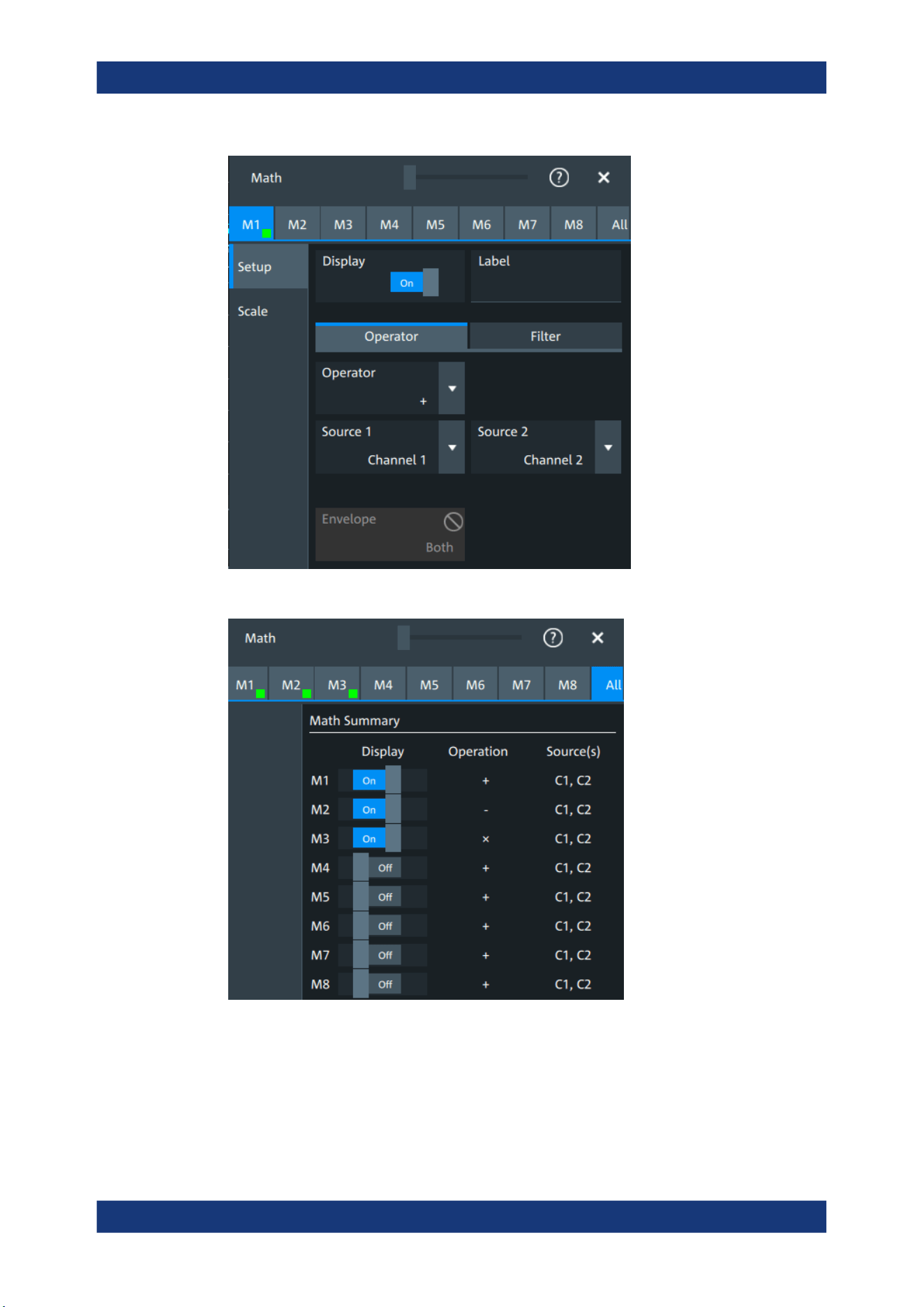

Waveform analysis
R&S
®
MXO 5 Series
167User Manual 1802.3369.02 ─ 02
Label
Adds a label to the math waveform.
Operator
Defines the type of operation to be performed on the selected signal sources.
The following functions are available:
"+"
Adds the values of 2 sources (channel or math waveform).
"-"
Subtracts source 2 from source 1.
"x"
Multiplies the two sources.
"/"
Divides source 1 by source 2.
"1/x"
Calculates the reciprocal of the source.
"- x"
Calculates the negative value of the source.
"|x|"
Determines the absolute value of the source.
"Δx/Δt"
Differentiates the source value relating to the time value.
Not possible on envelope waveforms and waveforms with "Peak
detect" decimation.
"Integral"
Calculates the definite integral of the source.
"log(x)"
Calculates the logarithm of the source value based on 10.
"ln(x)"
Calculates the natural logarithm of the source value (based on e).
"ld(x)"
Calculates the binary logarithm of the source value (binary logarithm,
based on 2).
"x
2
"
Squares the source. If the source contains negative values that have
been clipped, then the result contains positive clipping.
"√x"
Calculates the square root of the source. Note that the square root of
a negative number is undefined and the result is clipped.
"Rescale"
Rescaling of x.
Remote command:
CALCulate:MATH<m>[:EXPRession][:DEFine] on page 527
Source 1, Source 2
Defines the signal source to be evaluated by the math function.
a, b
Defines the values for the rescale function, if "Operator" = "Rescale"
"a"
Multiplication factor
"b"
Offset of the signal source on the y-axis.
Noise reject
Only available for "Operator" = "dx/dt".
Sets the number of neighboring samples that are skipped for differentiation.
To suppress noise effects during differentiation, it can be useful not to consider two
directly neighboring points to calculate dx (x
n
-x
n-1
). Instead, some samples in-between
are skipped and a point a few samples further is used (e.g. x
n
-x
n-3
).
Mathematics
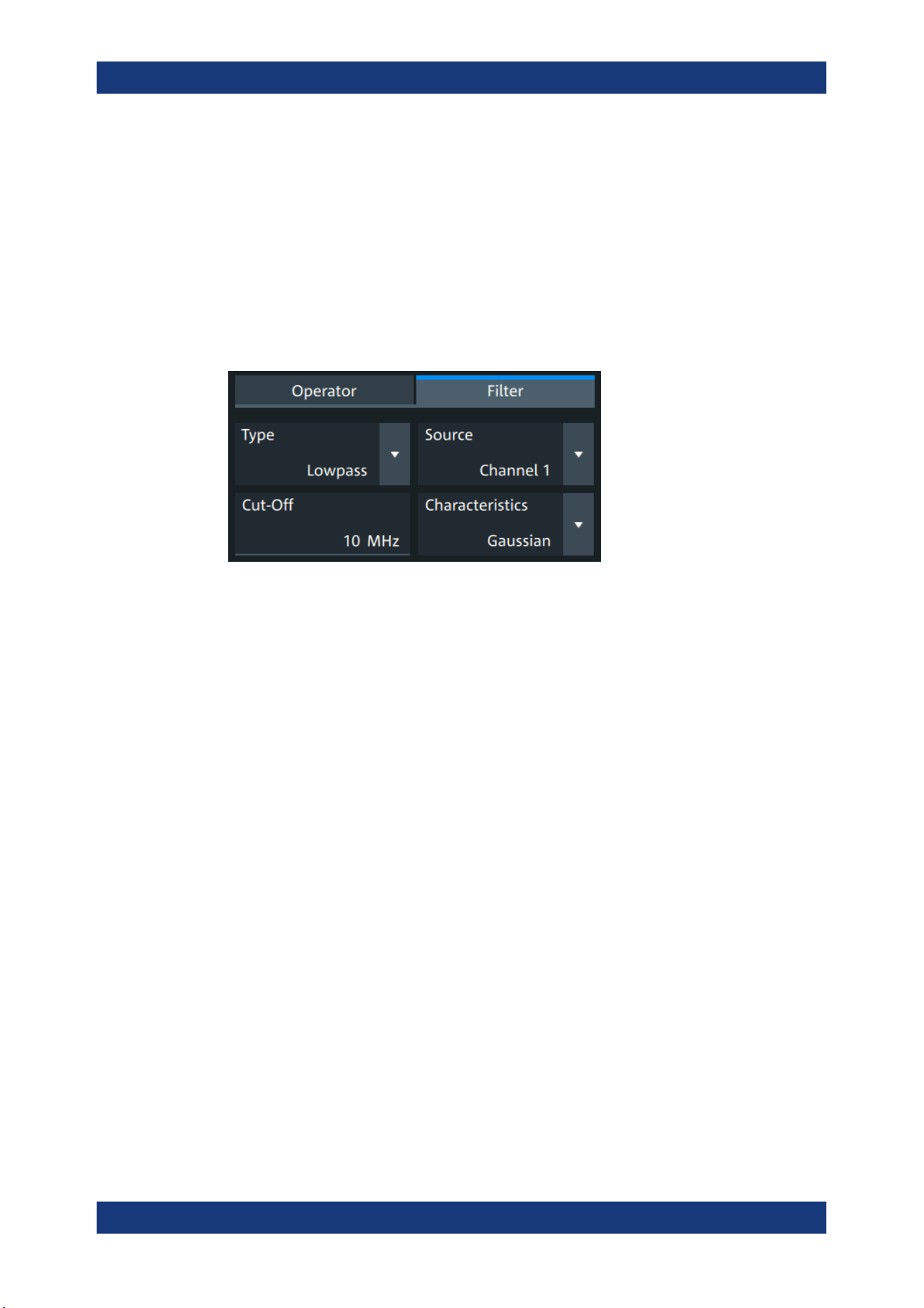
Waveform analysis
R&S
®
MXO 5 Series
168User Manual 1802.3369.02 ─ 02
Envelope wfm selection
Selects the upper or lower part of the input waveform for mathematic calculation, or a
combination of both.
Remote command:
CALCulate:MATH<m>:ENVSelection on page 529
8.2.3 Math filter
Access:[Math] > "Filter" tab
The finite impulse response filter is a filter to create filtered math waveforms with low-
pass or highpass. The filter requires additional settings.
In remote control, filter settings are defined in the expression string, see CALCulate:
MATH<m>[:EXPRession][:DEFine] on page 527.
Type
Selects, if the filter is highpass or lowpass.
Source 1
Selects the input channel of the signal.
Cut-off
Sets the limit frequency for the filter.
Cutoff frequency for lowpass filter
The cutoff frequency depends on the horizontal resolution and the filter characteristics.
The frequency for the lowpass filter can only be set in this range:
f_g_3dB = (0.001 ... 0.2)* f_a_in for Gaussian FIR filter
f_g_3dB = (0,001 ... 0.4)* f_a_in for rectangular FIR filter
Where: f_g_3dB = cutoff frequency to be set for the lowpass filter, and f_a_in = recipro-
cal of the resolution, or sample rate.
Cutoff frequency for highpass filter
To check limit frequency for the highpass filter, convert it to an equivalent lowpass fre-
quency:
f_LP = f_a_in/2 - f_HP
Mathematics
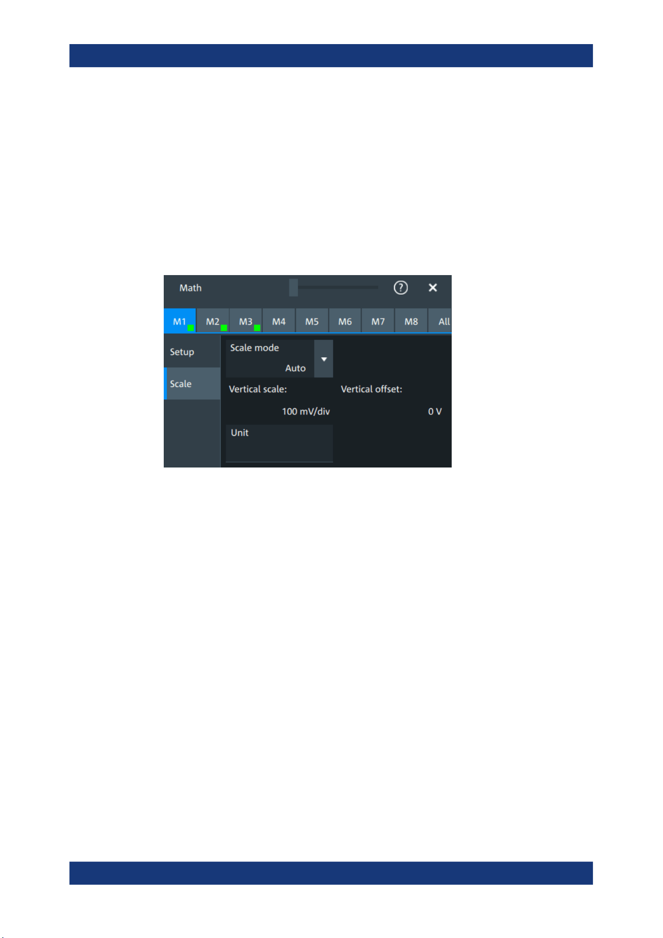
Waveform analysis
R&S
®
MXO 5 Series
169User Manual 1802.3369.02 ─ 02
Where f_HP is the requested highpass limit frequency and f_LP the equivalent lowpass
frequency that has to comply with the limits given above.
Characteristics
Selects if a Gaussian or a rectangular shape is used for the lowpass filter. The high-
pass filter is always Gaussian.
8.2.4 Math scale settings
Access:[Math] > "Scale" tab
Scale mode
By default, the vertical scale is adapted to the current measurement results automati-
cally to provide an optimal display. However, if necessary, you can define scaling val-
ues manually to suit your requirements.
"Manual"
Enter the required values for "Vertical scale" and "Vertical offset".
"Auto"
"Vertical scale" and "Vertical offset" are read-only.
Remote command:
CALCulate:MATH<m>:VERTical:SCALe:MODE on page 529
Vertical scale
Sets the scale of the y-axis in the math function diagram. The value is defined as
"<unit> per division", e.g. 50
mV/div. In this case, the horizontal grid lines are displayed
in intervals of 50 mV.
If Scale mode is set to "Auto", this setting is read-only.
Remote command:
CALCulate:MATH<m>:VERTical:SCALe[:VALue] on page 528
Vertical offset
Sets a voltage offset to adjust the vertical position of the math function on the screen.
Negative values move the waveform up, positive values move it down.
If Scale mode is set to "Auto", this setting is read-only.
Mathematics
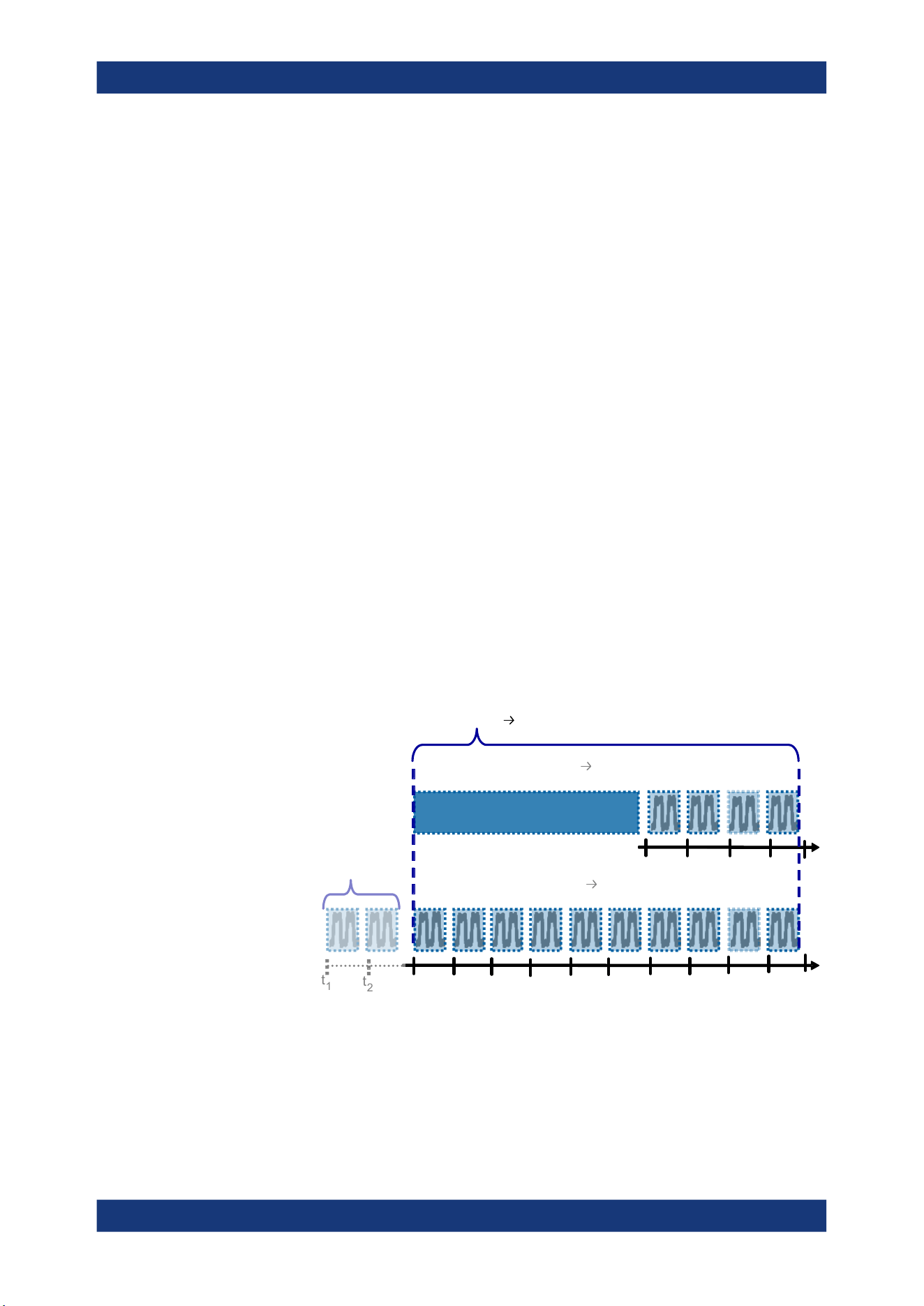
Waveform analysis
R&S
®
MXO 5 Series
170User Manual 1802.3369.02 ─ 02
Remote command:
CALCulate:MATH<m>:VERTical:OFFSet on page 528
Unit
Sets a user-defined unit for the math operation.
8.3 History
The history accesses the data of previous acquisitions and provides them for further
analysis.
8.3.1 About history
If a continuous acquisition runs, the captured data is stored in the sample memory and
the current acquisition is processed and shown on the display. After the acquisition is
stopped, the history accesses the captured samples that were stored, displays these
samples as history waveforms, and makes them available for further analysis. It con-
siders all channels that were enabled during the running acquisition.
When a new acquisition is started with [Single], the memory is cleared and written
anew. In continuous acquisition, stopping and starting the acquisition does not clear
the memory, and the history memory is continued. When the memory is full, new
acquisitions are stored, and the oldest are removed (first in, first out). The history mem-
ory is cleared when the acquisition parameters are changed. To clear the history mem-
ory on demand, use the [Clear] key or the "Clear" tool on the toolbar.
t
3
t
4
t
5
t
6
t
7
t
8
t
9
t
10
t
11
t
12
t
1
t
2
History
memory at
time = t
5
-3
-2
-1 0
t
1
t
2
t
3
t
4
4 waveforms acquired 4 history waveforms
Total memory 10 history waveforms
Discarded
earlier
waveforms
t
13
t
5
12 waveforms acquired 10 history waveforms
History
memory at
time = t
13
-3
-2
-1 0
-6
-5
-4
-9
-8
-7
Figure 8-1: History memory. In this example, the memory can store 10 waveforms.
The number of stored history waveforms depends on the memory size, the number of
enabled channels, and the record length. The shorter the record length, the less the
number of channels, and the larger the memory, the more history waveforms are
saved.
History
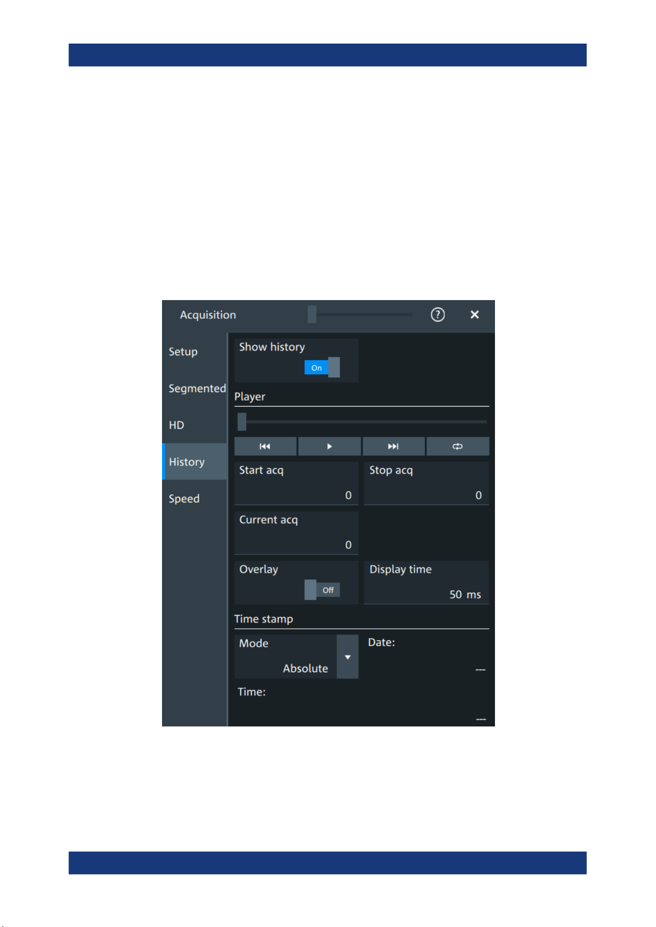
Waveform analysis
R&S
®
MXO 5 Series
171User Manual 1802.3369.02 ─ 02
You can work with history waveforms in the same way as with the waveform of the lat-
est acquisition: use zoom, cursors, measurements, create math waveforms and so on.
You can also save a single history waveform for further analysis.
8.3.2 History setup
The "History" dialog contains the complete functionality on history viewing and informa-
tion.
The most important information and functions are also provided in the quick-access
history dialog box.
Access: "Menu" > "Acquisition" > "History" tab.
Show history................................................................................................................172
Player.......................................................................................................................... 172
Start acq......................................................................................................................172
Stop acq...................................................................................................................... 172
Current acq................................................................................................................. 172
History

Waveform analysis
R&S
®
MXO 5 Series
172User Manual 1802.3369.02 ─ 02
Overlay........................................................................................................................173
Display time.................................................................................................................173
Time stamp..................................................................................................................173
Show history
Enables the history mode and allows you to save history waveforms to file.
The history display is enabled automatically when you press the [History] button. It is
disabled when you close the quick-access "History" dialog box.
Remote command:
ACQuire:HISTory[:STATe] on page 534
Player
The player can be used to control the playback of the history waveforms.
Sets the oldest acquisition in the sample memory as "Start acq" and
"Current acq".
Starts and stops the replay of the history waveforms from "Start acq"
to "Stop acq".
Sets the newest acquisition in the sample memory as "Stop acq" and
"Current acq". This acquisition always has the index "0".
"Auto repeat": If selected, the playback of the selected history seg-
ments repeats automatically. See also: "Auto repeat" on page 174.
Remote command:
ACQuire:HISTory:PLAY on page 531
Start acq
Sets the index of the first (oldest) acquisition to be displayed or exported. The index is
always negative.
Remote command:
ACQuire:HISTory:STARt on page 532
Stop acq
Sets the index of the last (newest) acquisition to be displayed or exported. The newest
acquisition of the complete acquisition series always has the index "0".
Remote command:
ACQuire:HISTory:STOP on page 532
Current acq
Accesses a particular acquisition in the memory to display it, or to save it. The newest
acquisition always has the index "0". Older acquisitions have a negative index.
If a history replay is running, the field shows the number of the currently shown acquisi-
tion.
Remote command:
ACQuire:HISTory:CURRent on page 531
History

Waveform analysis
R&S
®
MXO 5 Series
173User Manual 1802.3369.02 ─ 02
Overlay
Displays the segments with infinite persistence. Thus, you can see all data points of all
displayed segments of a player cycle. Same setting as "Infinite persistence"
on page 85.
Display time
Sets the display time for one acquisition. The shorter the time, the faster the replay is.
The setting takes effect for usual history replay and the display of a fast segmentation
series via the history.
Remote command:
ACQuire:HISTory:TPACq on page 532
Time stamp
The time stamp shows the time of the currently displayed history acquisition. Thus, the
time relation between acquisitions is always available.
The time stamp "Mode" can be absolute or relative:
●
In "Absolute" mode, the instrument shows the date and the daytime of the current
acquisition.
●
In "Relative" mode, the time difference to the newest acquisition (index = 0) is
shown.
During history replay, the time value is displayed and updated if the replay speed ("Dis-
play time") is slow enough, that is 40 ms or slower.
The quick-access history dialog box always shows the time according to the "Mode"
that is selected in the "Acquisition" > "History" tab.
Remote command:
ACQuire:HISTory:TSDate? on page 533
ACQuire:HISTory:TSABsolute? on page 532
ACQuire:HISTory:TSRelative? on page 533
ACQuire:HISTory:TSRReference? on page 533
8.3.3 Quick access history dialog
The quick access history dialog is visible when the history is active. Closing the dialog
disables the history display ("Show history" = "Off")
History

Waveform analysis
R&S
®
MXO 5 Series
174User Manual 1802.3369.02 ─ 02
Available acqs............................................................................................................. 174
Current acq................................................................................................................. 174
Time............................................................................................................................ 174
Auto repeat..................................................................................................................174
Play............................................................................................................... 174
Available acqs
Number of acquisitions that is saved in the memory and available for history viewing. It
is also the number of acquisitions in a fast segmentation acquisition series.
Remote command:
ACQuire:AVAilable? on page 471
Current acq
Index of the current acquisition, same as Current acq in the history setup.
Time
Shows the timestamp of the current acquisition. See "Time stamp" on page 173.
Auto repeat
If selected, the playback of the selected history segments repeats automatically.
Remote command:
ACQuire:HISTory:REPLay on page 531
Play
Starts and stops the replay of the history waveforms. See also: "Player" on page 172.
8.3.4 Using history
You can access the history waveforms in two ways:
●
Display a particular acquisition.
●
Replay all or a part of the saved waveforms to track the signal run.
To open the history and get information
1. Press the [History] key on the front panel.
A running acquisition is stopped, the history mode is enabled and the quick-access
"History" dialog box is displayed. The [History] key lights up as long as the history
mode is active.
2. Open the full configuration dialog box:
●
Tap the
icon.
● Open "Menu" > "Acquisition" dialog > "History" tab.
History
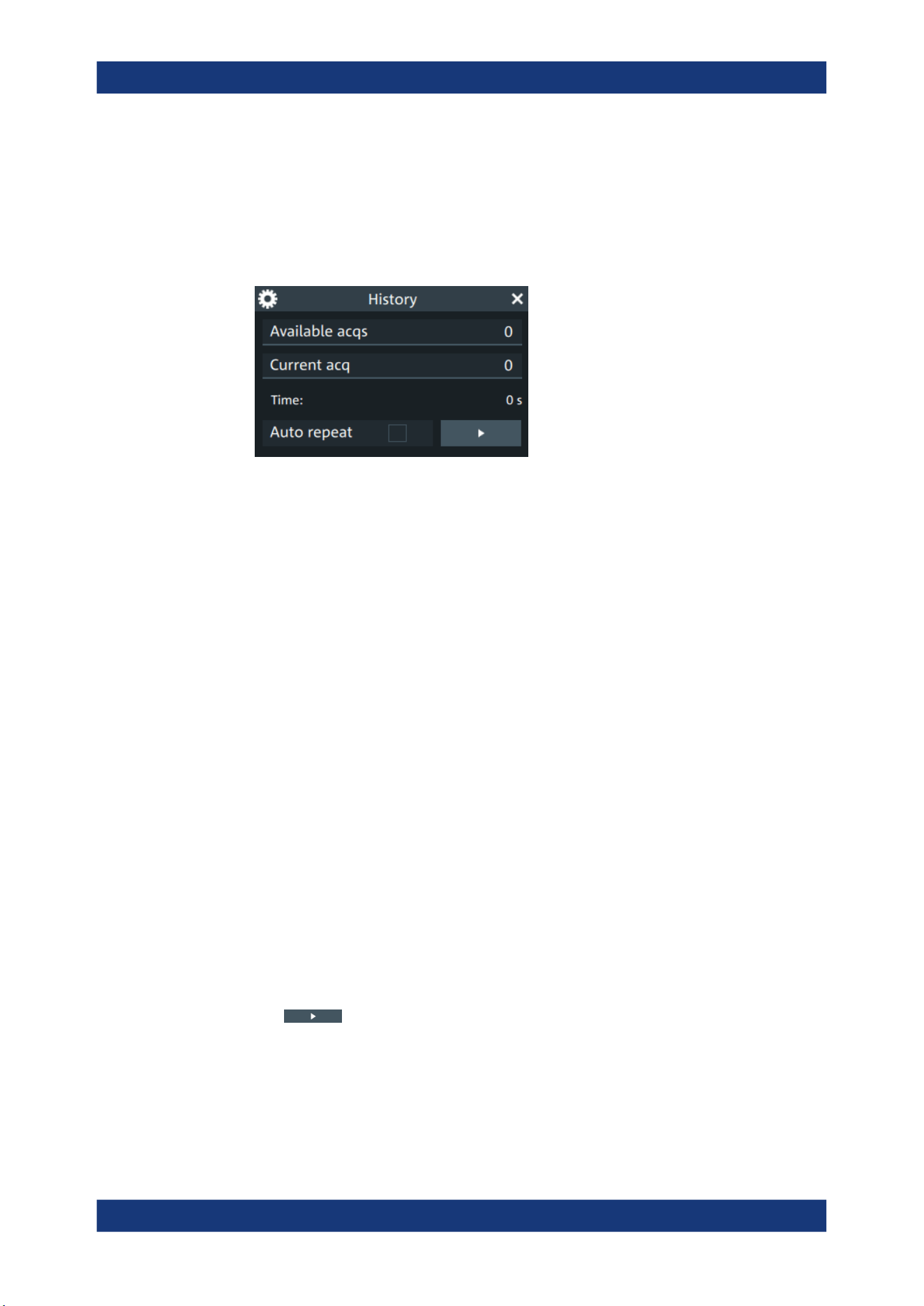
Waveform analysis
R&S
®
MXO 5 Series
175User Manual 1802.3369.02 ─ 02
To display a particular acquisition
You can analyze a selected history waveform, and save it to file.
► In the quick-access "History" dialog box, enter the number of the required acquisi-
tion in the "Current acq" field. The newest acquisition always has the index "0",
older acquisitions have a negative index.
Alternatively, you can configure and start the history display from the "History" configu-
ration dialog box:
1. Open the "History" configuration tab.
2. If the history mode is off (the [History] key is not illuminated), select "Show history".
3. Drag the slider to the required acquisition. The current number is shown in the
"Current acq" field.
Alternatively, enter the number of the required acquisition in the "Current acq" field.
To save a single history waveform
1. Select and display the required history waveform as described in "To display a par-
ticular acquisition" on page 175.
2. Save the selected waveform using "Save/Recall" > "Save" tab > "Waveform". For
details, see Chapter 12.2, "Save and recall waveform data", on page 271.
To replay history waveforms
If you want to see the complete acquisition series without any setup, simply tap in the
quick-access "History" dialog box. For specific analysis of history data, use the history
"Viewer" setup.
1. Open the "History" configuration dialog tab.
2. If the history mode is off (the [History] key is not illuminated), enable "Show his-
tory".
3.
Tap
to start.
To exit the history
► Choose one of the following ways:
● Close the quick-access "History" dialog box.
● In the "History" configuration tab, disable "Show history".
History

Waveform analysis
R&S
®
MXO 5 Series
176User Manual 1802.3369.02 ─ 02
● Start the acquisition.
8.4 Reference waveforms
You can configure up to four reference waveforms to display stored waveforms. Any
active signal, mathematical waveform or spectrum can be stored as a reference wave-
form. It can then be loaded again later to restore the waveform on the screen.
8.4.1 Working with reference waveforms
Reference waveforms can be displayed in addition to the signal waveforms.
To display a reference waveform
1. In the "Menu" > "Apps" > "General" tab, select "Reference".
Alternatively, press the [Ref] key.
2. Select the tab for the reference waveform that you want to display ("R1/2/3/4").
3. Load a stored reference waveform as described in To load a reference waveform.
Alternatively, select a source to be displayed as a reference:
a) In the "Setup" tab, select "Source".
b) Select the "Source" from the selection list. The list shows all active waveforms
that can be saved as references.
c) Tap the "Create/update" button to update the current reference waveform with
the source data.
4. Tap the "Show" button.
The reference waveform is displayed on the screen.
5. A reference waveform can have its own scaling settings or it can be scaled accord-
ing to the source settings. By default, the scaling of the reference waveform is cou-
pled to the source settings. Also, it can be stretched or compressed in vertical and
horizontal direction.
If necessary, change the settings on the "Vertical" and "Rescale" tabs of the "Refer-
ence Waveform" dialog.
To restore the original settings, tap the "Set to original" in the "Vertical" tab.
For a description of the scaling settings, see Chapter 8.4.2.4, "Reference waveform
rescale", on page 181.
To load a reference waveform
1. Press the [Ref] key.
2. Select the tab for the reference waveform that you want to load ("R1/2/3/4").
3. In the "Setup" tab, select "Recall".
4. Select the file from the file selection dialog box.
Reference waveforms
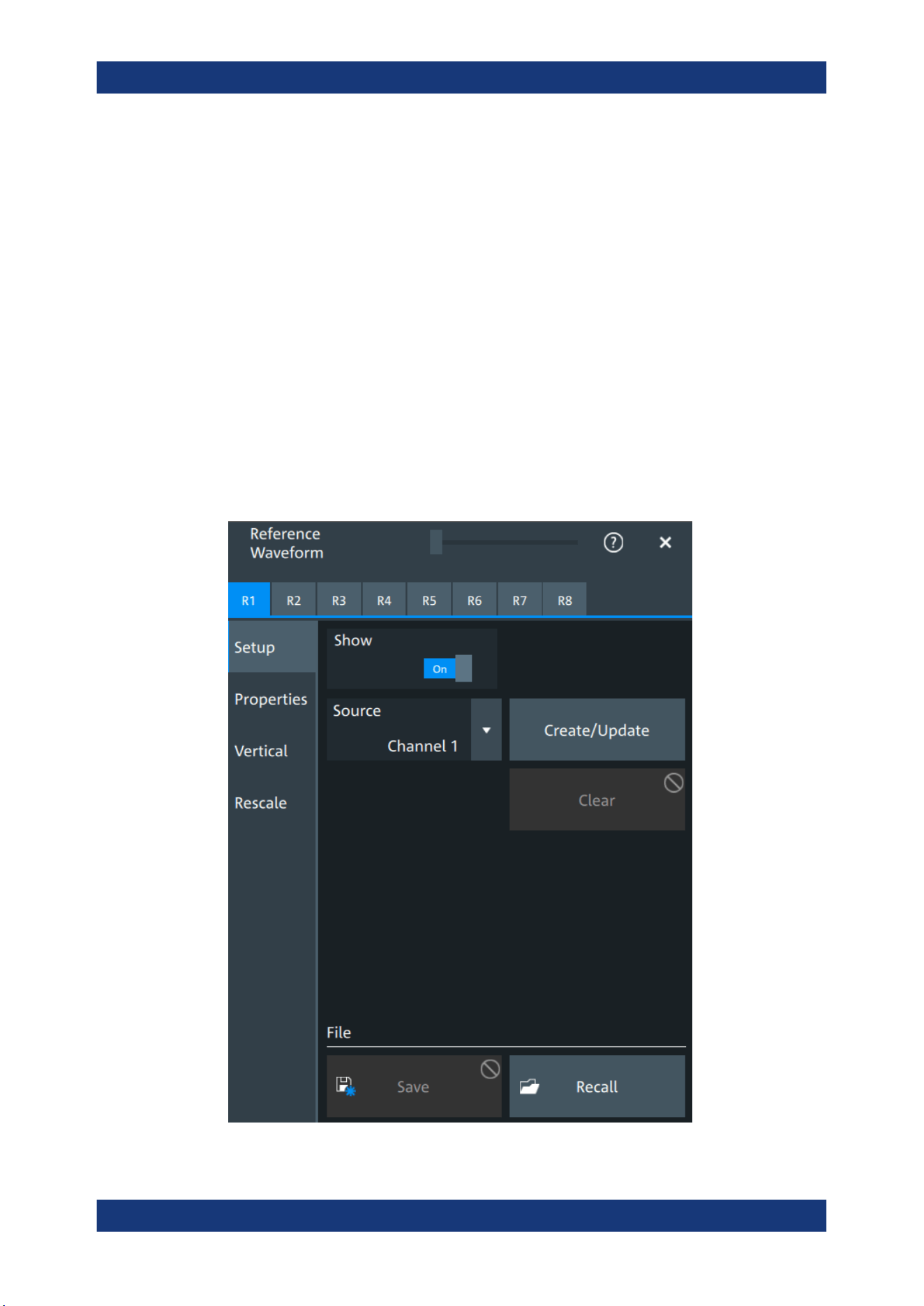
Waveform analysis
R&S
®
MXO 5 Series
177User Manual 1802.3369.02 ─ 02
5. To load the waveform from the specified file, tap "Open".
The selected waveform is loaded as the specified reference waveform.
8.4.2 Settings for reference waveforms
To compare waveforms and analyze differences between waveforms, you can use up
to eight reference waveforms R1 to R8.
Each reference waveform has its own memory on the instrument. You can also save
an unlimited number of reference waveforms and load them for further use.
The display of a reference waveform is independent from the display of the source
waveform; you can move, stretch and compress the curve vertically and horizontally.
8.4.2.1 Reference waveform setup
Access: [Ref] key > "Setup" tab
Reference waveforms

Waveform analysis
R&S
®
MXO 5 Series
178User Manual 1802.3369.02 ─ 02
In the "Setup" tab, you select the target reference waveform and its source.
R1/2/3/4
Each tab contains the settings for one of the available reference waveforms.
Show
Enables the display of the reference waveform in the diagram.
Remote command:
REFCurve<rc>:STATe on page 536
Source
Selects the source waveform from the active waveforms, e.g. input channels, math
waveforms, or spectrum.
Remote command:
REFCurve<rc>:SOURce on page 536
Create/update
Copies the selected source waveform with all its settings to the memory of the refer-
ence waveform. If there is a previously defined reference waveform in this memory, it is
updated by the current source waveform. If the acquisition is running, the reference
waveform is a snapshot.
A progress bar informs you about the process, see "Progress information" on page 66.
Remote command:
REFCurve<rc>:UPDate on page 537
Clear
The selected reference waveform disappears, its memory is deleted.
Remote command:
REFCurve<rc>:CLEar on page 534
Save
Saves the reference waveform. The complete reference waveform is stored in a REF
file and can be reloaded later.
A progress bar informs you about the process, see "Progress information" on page 66.
If you want to save only a part of the waveform, or need CSV format, use "Menu" key >
"Save/Recall" key > "Save" tab > "Waveform".
See also:
●
Chapter 12.2, "Save and recall waveform data", on page 271
●
Chapter 12.2.3, "Waveform export files", on page 274
Remote command:
REFCurve<rc>:SAVE on page 536
To abort the saving, use REFCurve<rc>:ABORt on page 534.
Recall
Opens a file selection dialog box and loads the selected reference waveform file.
Reference waveforms
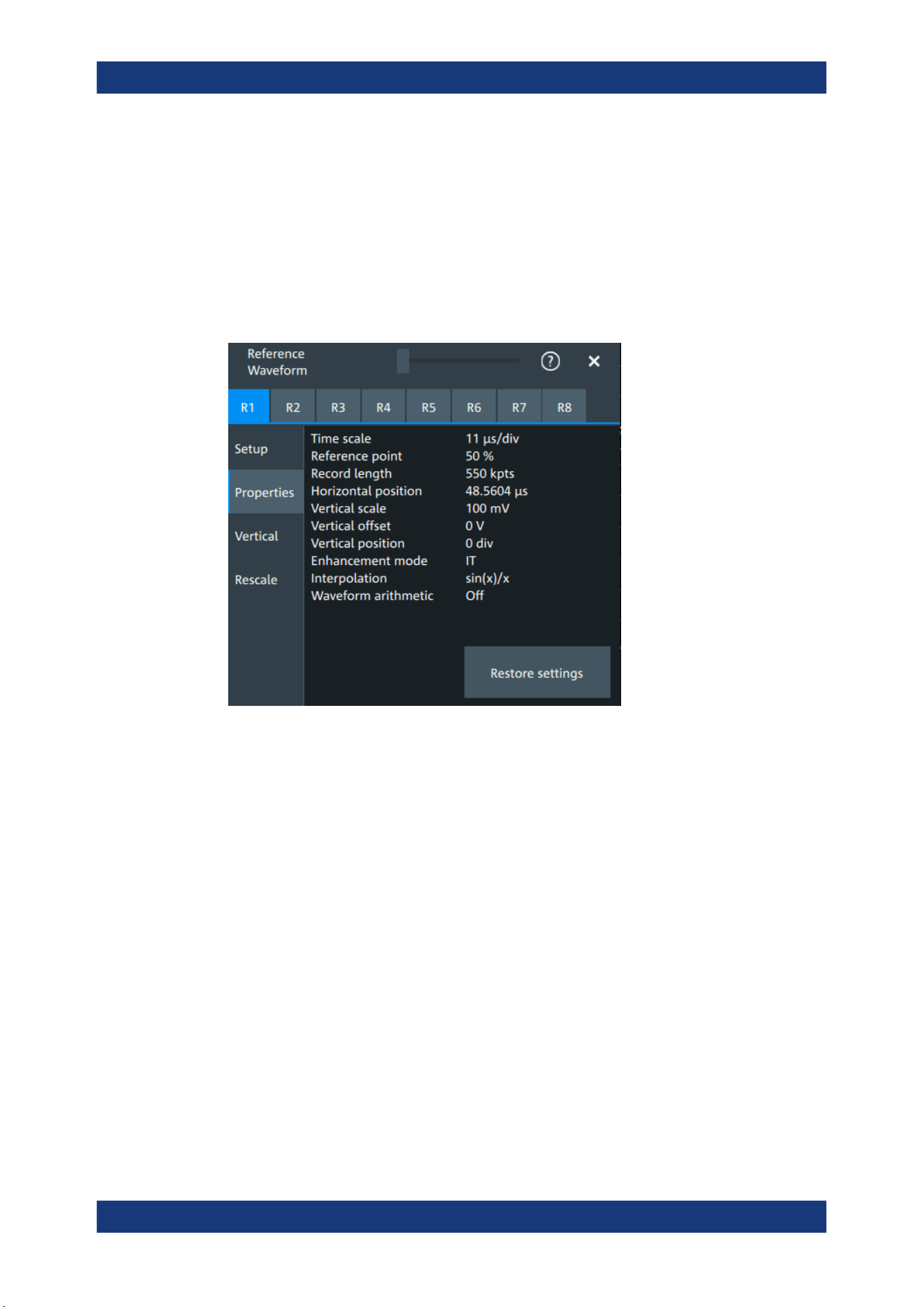
Waveform analysis
R&S
®
MXO 5 Series
179User Manual 1802.3369.02 ─ 02
Note that reference waveforms can be loaded only from .ref files. Other formats are
meant for further processing in other applications.
Remote command:
REFCurve<rc>:OPEN on page 535
8.4.2.2 Reference waveform properties
Access: [Ref] key > "Properties" tab
A reference waveform can be scaled, stretched and positioned in the diagram. The
"Properties" tab shows the original settings of the reference waveform, which are
stored together with the waveform data.
The following settings are displayed:
●
Time scale
●
Reference point
●
Record length, Record length limit
●
Position
●
Vertical scale
●
Offset
●
Position
●
Enhancement mode
●
Interpolation
●
Waveform arithmetic
Reference waveforms
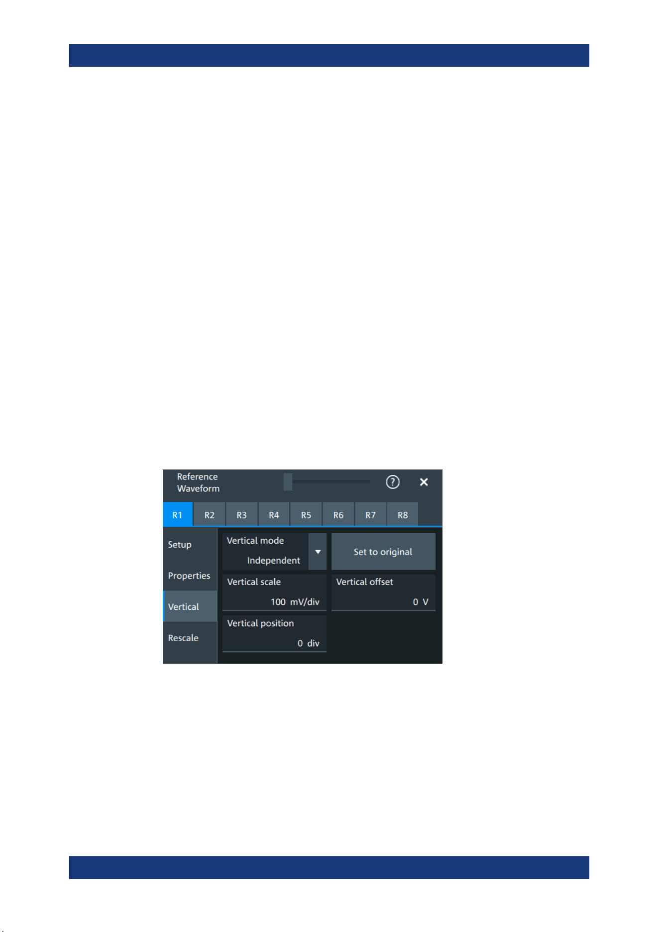
Waveform analysis
R&S
®
MXO 5 Series
180User Manual 1802.3369.02 ─ 02
Enhancement mode
The enhancement mode is taken from the source waveform of the reference. The
enhancement mode is set automatically by the instrument and depends on the sample
rate. As long as the waveform sample rate is not higher than the ADC sample rate, the
instrument works automatically in real time mode (RT). At higher waveform sample
rates, the instrument changes to interpolated time mode (IT), where interpolation adds
waveform points between the captured ADC samples by various mathematical meth-
ods, see Interpolation.
Waveform arithmetic
The waveform arithmetic is taken from the source waveform of the reference, and it
cannot be changed for the reference. Waveform arithmetic builds the resulting wave-
form from several consecutive acquisitions of the signal. The arithmetic methods are
envelope and average, which are set in the Acquisition mode.
Restore settings
Applies the original settings of the reference waveform to the horizontal and vertical
settings of the selected waveform.
Remote command:
REFCurve<rc>:RESTore on page 535
8.4.2.3 Reference waveform vertical
Access: [Ref] key > "Vertical" tab
Mode
Selects the type of vertical settings:
"Coupled to
source"
Vertical position and scale of the source are used.
"Independent"
Scaling and position can be set specific to the reference waveform.
Remote command:
REFCurve<rc>:VMODe on page 541
Reference waveforms

Waveform analysis
R&S
®
MXO 5 Series
181User Manual 1802.3369.02 ─ 02
Set to original
Available, if "Mode" = "Independent".
Restores the original vertical settings of the reference waveform (vertical scale, posi-
tion, and offset).
Remote command:
REFCurve<rc>:TOORiginal on page 540
Vertical scale
Available, if "Mode" = "Independent".
Sets the vertical scale, which defines the displayed amplitude of the selected wave-
form.
The unit of the reference is the same as the unit of the source waveform.
Remote command:
REFCurve<rc>:SCALe on page 537
Vertical offset
The vertical offset moves the reference waveform vertically. Enter a value with the unit
of the waveform.
Remote command:
REFCurve<rc>:OFFSet on page 535
Vertical position
Available, if "Mode" = "Independent".
Moves the reference waveform up or down in the diagram.
Remote command:
REFCurve<rc>:POSition on page 538
8.4.2.4 Reference waveform rescale
Access: [Ref] key > "Rescale" tab
Reference waveforms
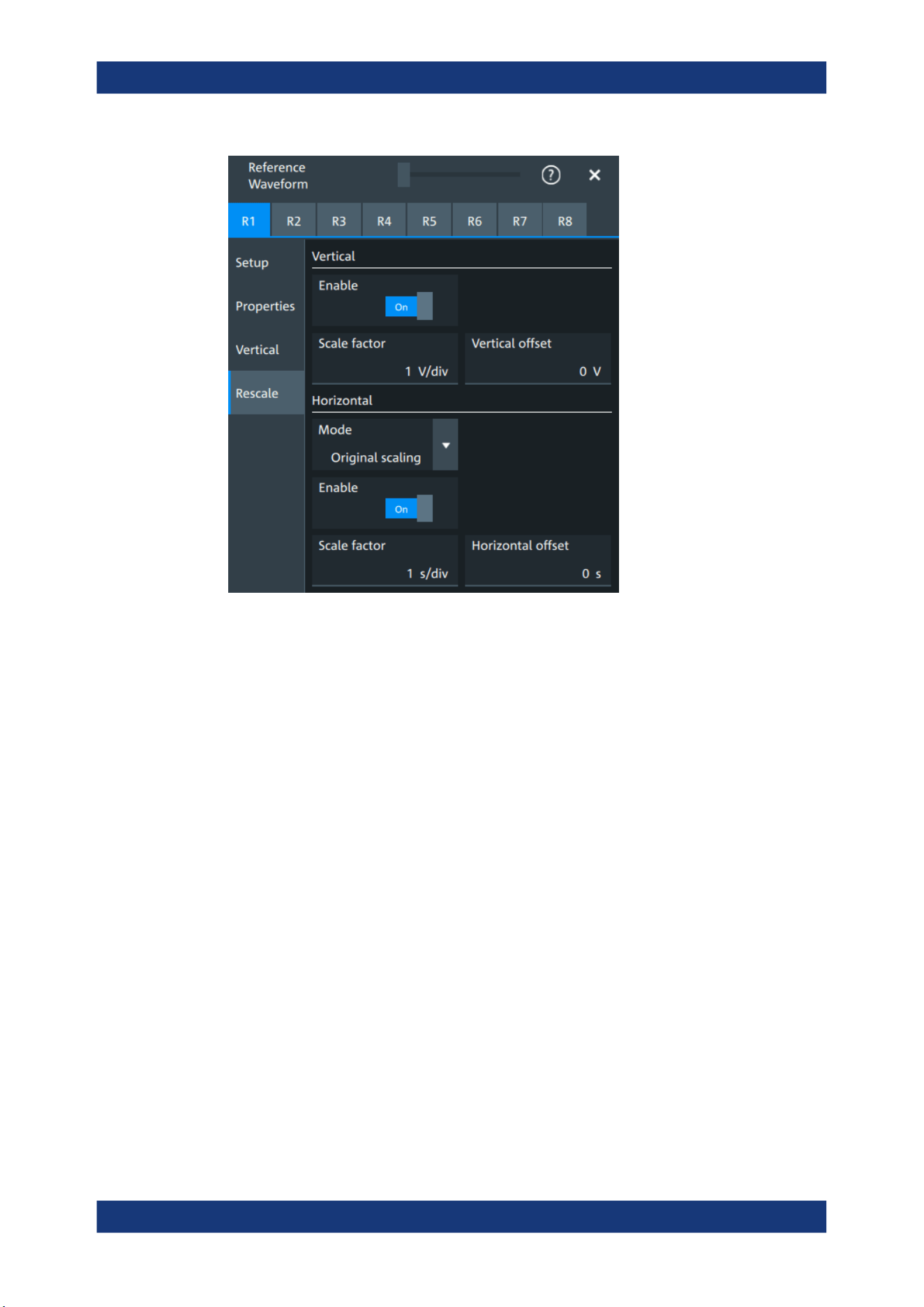
Waveform analysis
R&S
®
MXO 5 Series
182User Manual 1802.3369.02 ─ 02
In the "Rescale" tab you can adjust the vertical and horizontal scaling of the reference
waveform.
Vertical
Stretching and offset change the display of the waveform independent of the vertical
scale and position.
Enable ← Vertical
If enabled, the vertical offset and factor are applied to the reference waveform.
Remote command:
REFCurve<rc>:RESCale:VERTical:STATe on page 540
Scale factor ← Vertical
Sets the vertical scale factor. A factor greater than 1 stretches the waveform vertically,
a factor lower than 1 compresses the curve.
Remote command:
REFCurve<rc>:RESCale:VERTical:FACTor on page 539
Vertical offset ← Vertical
The vertical offset moves the reference waveform vertically. Enter a value with the unit
of the waveform.
Like vertical offset of a channel waveform, the offset of a reference waveform is sub-
tracted from the measured value. Negative values shift the waveform up, positive val-
ues shift it down.
Reference waveforms

Waveform analysis
R&S
®
MXO 5 Series
183User Manual 1802.3369.02 ─ 02
Remote command:
REFCurve<rc>:RESCale:VERTical:OFFSet on page 540
Horizontal
Stretching and offset change the display of the waveform independent of the horizontal
settings of the source waveform and of the horizontal diagram settings.
Mode ← Horizontal
Selects the type of horizontal settings:
"Original scal-
ing"
Horizontal scaling and reference point of the source waveform are
used.
"Adjust to X
Axis"
The current horizontal settings of the diagram are used.
Remote command:
REFCurve<rc>:HMODe on page 538
Enable ← Horizontal
If enabled, the horizontal offset and factor are applied to the reference waveform.
Remote command:
REFCurve<rc>:RESCale:HORizontal:STATe on page 539
Scale factor ← Horizontal
Sets the horizontal scale factor. A factor greater than 1 stretches the waveform hori-
zontally, a factor lower than 1 compresses the curve.
Remote command:
REFCurve<rc>:RESCale:HORizontal:FACTor on page 538
Horizontal offset ← Horizontal
Moves the waveform horizontally. Enter a value with a time unit suitable for the time
scale of the diagram.
Positive values shift the waveform to the right, negative values shift it to the left.
Remote command:
REFCurve<rc>:RESCale:HORizontal:OFFSet on page 539
Reference waveforms

Measurements
R&S
®
MXO 5 Series
184User Manual 1802.3369.02 ─ 02
9 Measurements
Using the R&S MXO 5 you can perform and display different measurements simultane-
ously, based on the active signal or math waveforms. The color of the results in the
result table corresponds with the source waveform color.
9.1 Cursor measurements
● Cursors and results of cursor measurements....................................................... 184
● Using cursors........................................................................................................ 185
● Settings for cursor measurements........................................................................ 187
9.1.1 Cursors and results of cursor measurements
Cursor measurements determine the results at the current cursor positions. The cur-
sors can be positioned manually, or can be configured to follow the waveform. You can
measure on one waveform, or on two different waveforms (sources).
Up to 4 cursor sets can be configured and displayed. Each cursor set consists of a pair
of horizontal or vertical cursors, or both. Cursor lines can be coupled so that the initially
defined distance is always maintained.
The cursors are displayed in the diagrams of the source waveform only, or in all dia-
grams. For each measurement, labels can be defined for the cursors. By default, the
cursors are labeled as Cu1.1 and Cu1.2.
How to set up cursor measurements is described in Chapter 9.1.2, "Using cursors",
on page 185. The Chapter 9.1.3, "Settings for cursor measurements", on page 187
provides a detailed description of all settings.
For details on using the result table, see Chapter 4.9, "Displaying results", on page 62.
9.1.1.1 Cursor measurements on time-based waveforms
The cursor for measurement on time-based waveforms returns the following results.
The results are displayed automatically when a cursor measurement is enabled.
Label Description
"X1, X2" Time at the position of the vertical cursors.
"Y1, Y2" Vertical values of the waveform at the position of the horizontal cursors in V or
A.
"dx" Difference between the vertical cursor (time) values
Cursor measurements
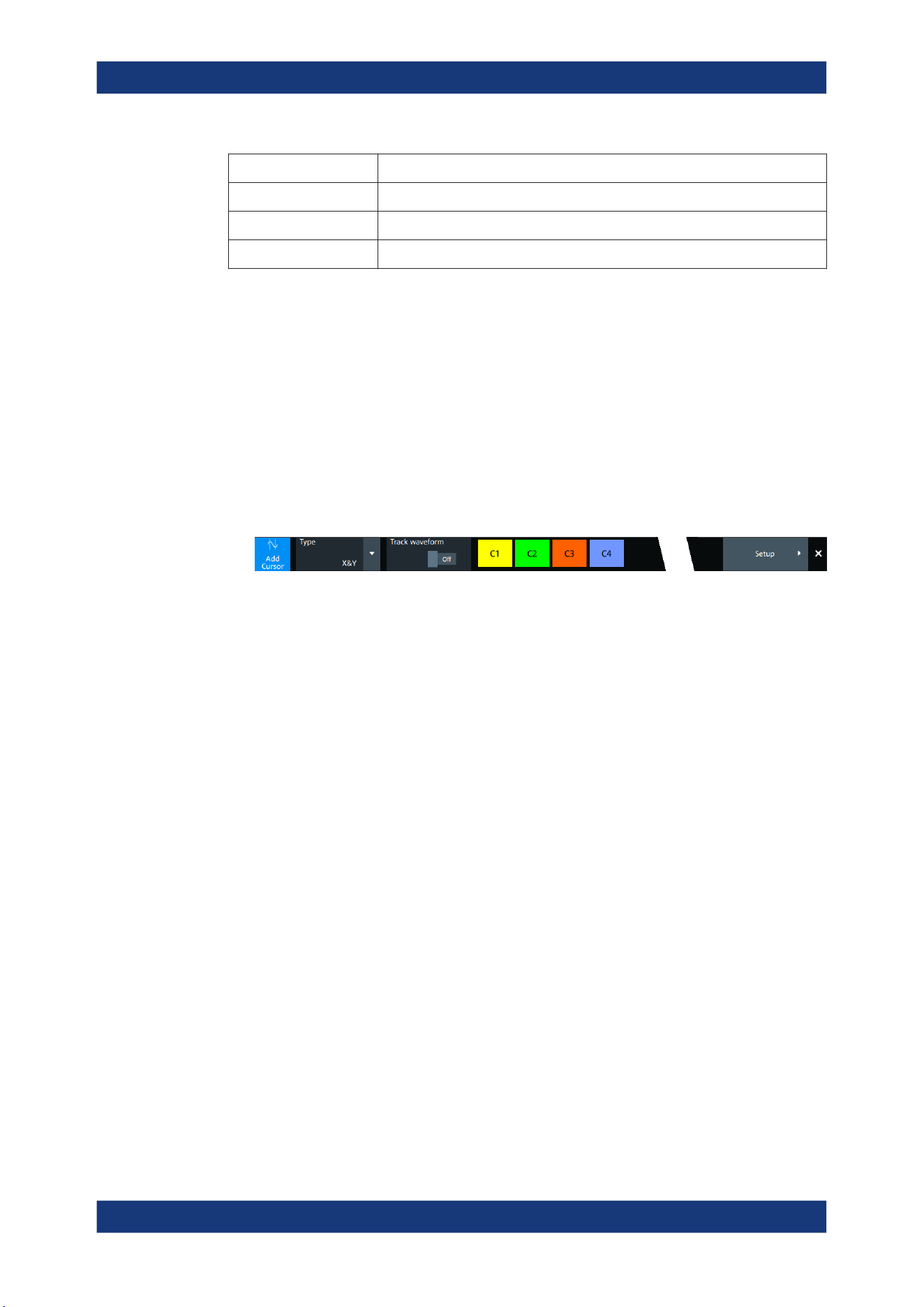
Measurements
R&S
®
MXO 5 Series
185User Manual 1802.3369.02 ─ 02
Label Description
"1/dx" Inverse time difference
"dy" Difference between the horizontal cursor values
"dy/dx" Slope of the waveform between the cursors (if measured on one source)
9.1.2 Using cursors
You can start cursor measurements by using the toolbar, or using the [Cursor] key. For
detailed configuration, use the "Cursor" dialog box.
9.1.2.1 Starting a simple cursor measurement
To add cursors using the toolbar
1. Tap the "Add cursor" icon on the toolbar.
2. Select the channel that you want to apply the cursor to.
Tap the waveform that you want to measure. Alternatively, you can draw a rectan-
gle in the diagram to position the cursor lines.
The cursor lines appear and the cursor results are displayed in a table or result
box.
To display cursors using the [Cursor] key
1. Select the waveform that you want to measure.
2. Press the [Cursor] key.
The cursor lines and the measurement results are displayed.
9.1.2.2 Configuring a cursor measurement
To modify the position of the cursor lines, you can drag the lines on the screen. In addi-
tion, various settings are possible to refine the measurement.
The complete configuration of cursor measurements is provided in the "Cursor" dialog.
1. To open the "Cursor" dialog, use one of these ways:
● Open the "Menu" > "Cursor".
● Press the [Cursor] key.
● Double-tap in the results table (but not on a result).
2. Select the "Setup" tab.
3. Select the subtab for the cursor set that you want to use.
Cursor measurements

Measurements
R&S
®
MXO 5 Series
186User Manual 1802.3369.02 ─ 02
4. Select the "Source" - the measured waveform. You can select any input channel, or
various other active waveforms. Available sources are shown in the source list.
5. If necessary, enable the "Second source". Select a waveform for "Source 2".
6. Select the "Type": X (vertical), Y (horizontal), or XY (both).
7. Define the position of the cursors:
a) To define exact positions of the cursor lines, enter the X-position for each verti-
cal cursor and the Y-position for each horizontal cursor.
If it is not possible to set horizontal cursors, disable "Track waveform".
b) To position the horizontal cursors automatically, select "Track waveform".
In this case, Cu 1.1 indicates the current maximum, Cu 1.2 indicates the cur-
rent minimum. If both horizontal and vertical cursors are displayed, the horizon-
tal cursors are placed at the crossing points of the vertical cursors with the
waveform. Adjust the vertical cursors manually, and the horizontal cursors fol-
low.
8. To display the cursor in all diagrams that are in the same domain as the selected
source (time or spectrum), enable "Show in all diagrams" in the "Advanced" tab.
9. To set the cursors for a spectrum measurement to peak values, select the "Peak
search" tab.
Tap one of the buttons to place the cursors on the selected peak value. For details,
see Chapter 9.1.3.3, "Peak search tab", on page 191.
10. Tap the "Type" button in the "Setup" tab to activate the cursor measurement.
The cursors lines and the results are displayed. For details on cursor measurement
results, see Chapter 9.1.1, "Cursors and results of cursor measurements",
on page 184.
9.1.2.3 Configuring the cursor display
By default, the cursors are displayed as lines in the diagrams and labeled according to
the syntax: Cu<cursor set number>.<1|2>
For example, the cursors for the cursor set 2 are labeled 2.1 and 2.2. The horizontal
and the vertical cursors lines have the same labels.
You can change the default cursor display and labels.
To set the cursor style
1. Press the [Cursor] key.
2. Select the subtab for the cursor set you want to configure.
3. Select the "Setup" tab.
4. Select the "Cursor style". See also: "Cursor style" on page 188.
Cursor measurements
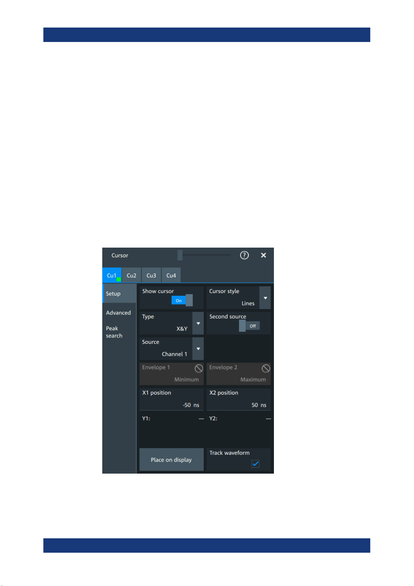
Measurements
R&S
®
MXO 5 Series
187User Manual 1802.3369.02 ─ 02
To add labels to cursor lines
1. Press the [Cursor] key.
2. Select the subtab for the cursor set you want to configure.
3. Select the "Advanced" tab.
4. Enter a label for "Vertical cursor 1", "Vertical cursor 2", "Horizontal cursor 1", "Hori-
zontal cursor 2".
5. Enable "Show label".
9.1.3 Settings for cursor measurements
Cursor measurements are configured in the "Cursor" dialog box.
9.1.3.1 Setup tab
The "Setup" tab contains the settings for cursor measurements.
Cursor measurements

Measurements
R&S
®
MXO 5 Series
188User Manual 1802.3369.02 ─ 02
Cu1/Cu2
The settings for each cursor measurement (or cursor set) are configured on separate
tabs. For each cursor set, a horizontal pair of cursors, a vertical pair of cursors, or both
can be displayed.
Show cursor
Enables the selected cursor measurement.
Remote command:
CURSor<cu>:STATe on page 579
Cursor style
Defines how the cursor is displayed in the diagram.
"Lines"
The cursors are displayed as lines.
"Line & Rhombus"
The cursors are displayed as lines. The intersections of the cursors
with the waveforms are displayed by rhombus-shaped points.
"VLine & Rhombus"
Vertical line and rhombus: the cursors are displayed as vertical lines.
The intersections of the cursors with the waveforms are displayed by
rhombus-shaped points.
"Rhombus"
The intersections of the cursors with the waveforms are displayed by
rhombus-shaped points.
Remote command:
CURSor<cu>:STYLe on page 587
Type
Defines the cursor type to be used for the measurement.
"X" (vertical cursors )
Both vertical cursor lines are set automatically to the trigger position,
and you can reposition them manually.
"Y" (horizontal cursors)
Horizontal cursors are positioned automatically along the waveform
and can be adjusted manually.
"X&Y" (both vertical and horizontal cursors)
Horizontal cursors are positioned automatically along the waveform
and vertical cursors are set to the trigger position. You can reposition
all cursor lines manually.
Remote command:
CURSor<cu>:FUNCtion on page 579
Second source, Source 2
Enables and selects a second source for the cursor measurements. If enabled, the
second cursor lines Cu2 measure on the second source. Using a second source, you
can measure differences between two channels with cursors.
Cursor measurements

Measurements
R&S
®
MXO 5 Series
189User Manual 1802.3369.02 ─ 02
Remote command:
CURSor<cu>:USSource on page 580
CURSor<cu>:SSOurce on page 580
Source
Defines the source of the cursor measurement. Any of the input signal, math or refer-
ence waveforms can be selected.
Remote command:
CURSor<cu>:SOURce on page 579
Envelope, Envelope 2
Define which horizontal cursor is positioned to the maximum and which to the minimum
envelope values.
Envelope selection is effective under the following conditions:
●
The acquisition mode of the cursor source waveform is set to envelope, see Acqui-
sition mode.
●
Track waveform is enabled.
●
Both horizontal and vertical cursors are enabled (Type = "X&Y").
"Minimum"
The horizontal cursor is set to the crossing point of the vertical cursor
with the minimum waveform envelope.
"Maximum"
The horizontal cursor is set to the crossing point of the vertical cursor
with the maximum waveform envelope.
Remote command:
CURSor<cu>:X1ENvelope on page 583
CURSor<cu>:X2ENvelope on page 583
X1 position, X2 position
Define the left and right position of the vertical cursors.
Remote command:
CURSor<cu>:X1Position on page 580
CURSor<cu>:X2Position on page 581
Y1 position, Y2 position
Define the upper and lower position of the horizontal cursor lines.
If Track waveform is enabled, the user setting is disabled and the measurement results
are displayed in the result table.
Remote command:
CURSor<cu>:Y1Position on page 581
CURSor<cu>:Y2Position on page 581
Track waveform
The horizontal cursors track the waveform. The first cursor line indicates the current
vertical minimum, and the second cursor line indicates the maximum. If the waveform
changes, e.g. during a running measurement, the cursors move along with it.
If both horizontal and vertical cursors are displayed, the horizontal cursors are posi-
tioned to the crossing points of the vertical cursors with the waveform. The measure-
ment results are displayed in the cursor result box.
Cursor measurements
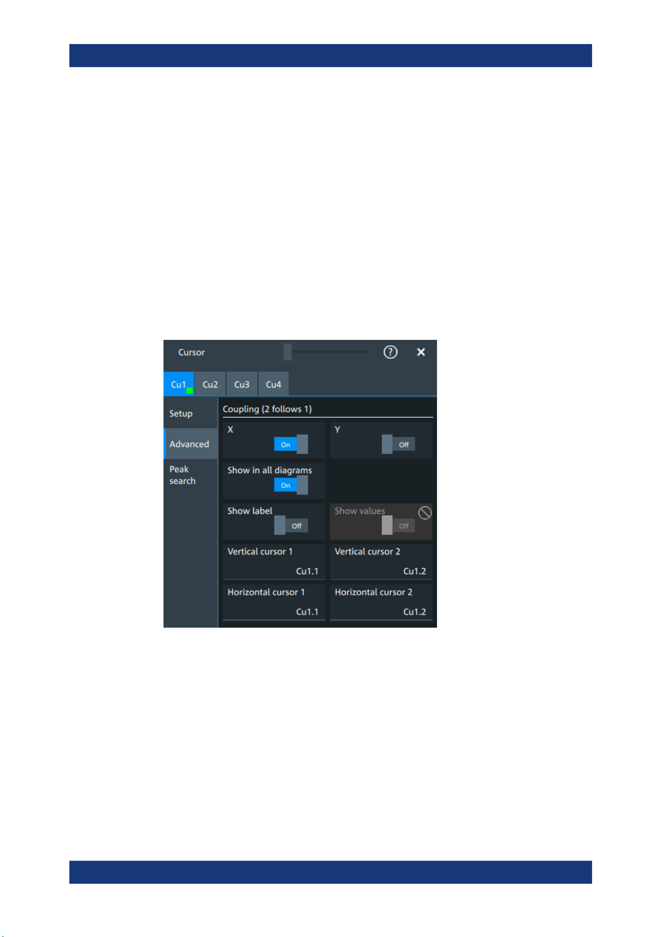
Measurements
R&S
®
MXO 5 Series
190User Manual 1802.3369.02 ─ 02
Remote command:
CURSor<cu>:TRACking[:STATe] on page 582
Place on display
Resets the cursors to their initial positions. Reset is helpful if the cursors have disap-
peared from the display or need to be moved for a larger distance.
9.1.3.2 Advanced settings
Access: Cursor key > "Advanced" tab
The settings in the "Advanced" cursor tab configure the behavior and display of cursor
lines, and labels for the lines.
The cursor style and position of the measurement results is defined in the "Settings" >
"Appearance" > "Cursor" dialog box.
X, Y
Couple the horizontal or vertical cursor lines so that the distance between the two lines
remains the same if one cursor is moved. "X" couples the vertical cursor lines, and "Y"
couples the horizontal cursor lines.
Remote command:
CURSor<cu>:XCOupling on page 582
CURSor<cu>:YCOupling on page 583
Show in all diagrams
Shows the enabled cursor measurements in all active diagrams of the same (time/
spectrum) domain.
Cursor measurements
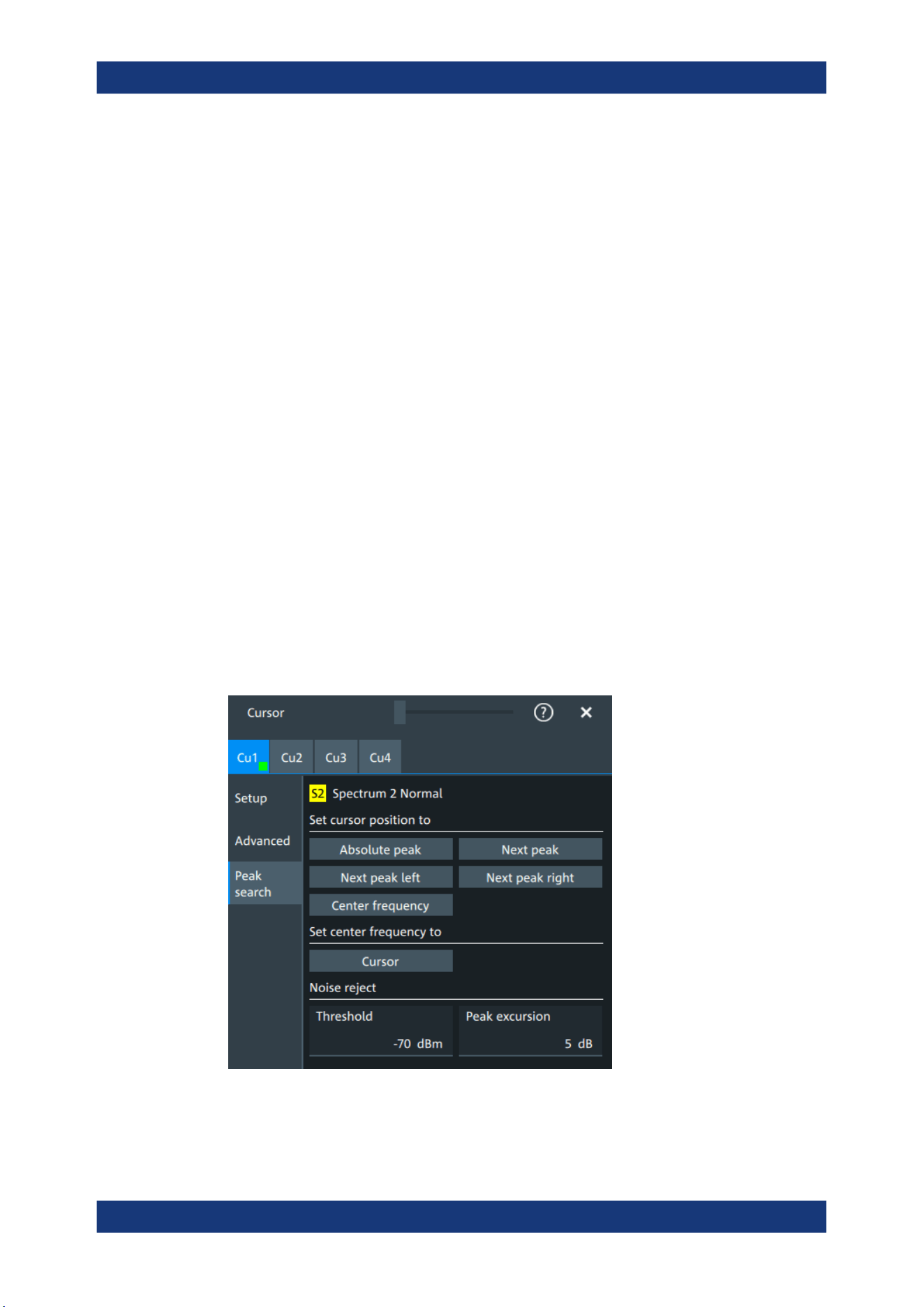
Measurements
R&S
®
MXO 5 Series
191User Manual 1802.3369.02 ─ 02
Remote command:
CURSor<cu>:SIAD on page 582
Show label
Shows the cursor labels in the diagram.
Remote command:
CURSor<cu>:LABel on page 582
Show values
Displays the values of the labels.
Vertical cursor 1, Vertical cursor 2
Defines a label to be displayed with the vertical cursors.
By default, the cursors are labeled as Cu1.1, Cu1.2, Cu2.1, Cu2.2.
Horizontal cursor 1, Horizontal cursor 2
Defines a label to be displayed with the horizontal cursors.
9.1.3.3 Peak search tab
Access: [Cursor] key > "Peak search" tab
The settings on this tab are only available in spectrum mode, i.e. the source of the cur-
sor measurement is a spectrum. In this case, the cursors can indicate the results of a
peak search on the waveform. You can define which peaks the instrument determines
by defining the noise reject settings.
Absolute peak
Sets both cursors to the absolute peak value.
Cursor measurements

Measurements
R&S
®
MXO 5 Series
192User Manual 1802.3369.02 ─ 02
Remote command:
CURSor<cu>:MAXimum[:PEAK] on page 586
Next peak
Cursor 2 is set to the next smaller absolute peak from the current position.
Remote command:
CURSor<cu>:MAXimum:NEXT on page 587
Next peak left
Cursor 2 is set to the next peak to the left of the current position.
Remote command:
CURSor<cu>:MAXimum:LEFT on page 586
Next peak right
Cursor 2 is set to the next peak to the right of the current position.
Remote command:
CURSor<cu>:MAXimum:RIGHt on page 586
Center frequency
Sets the vertical cursor line Cu1 to the center frequency.
Remote command:
CURSor<cu>:FFT:TOCenter on page 586
Set center frequency to
Sets the center frequency to the frequency value that is measured at cursor line Cu1.
Remote command:
CURSor<cu>:FFT:SETCenter on page 585
Threshold
Sets an absolute threshold as an additional condition for the peak search. Only peaks
that exceed the threshold are detected.
This setting is only available for spectrum waveforms. It is valid for cursor measure-
ments, spectrum measurements and peak search.
Remote command:
CALCulate:SPECtrum<sp>:THReshold on page 594
CURSor<cu>:THReshold on page 587
Peak excursion
Defines a relative threshold, the minimum level value by which the waveform must rise
by to be considered as a peak. For the peak to be considered, the excursion threshold
must be met both on the left and the right sides of the peak.
To avoid identifying noise peaks, enter a peak excursion value that is higher than the
noise levels.
This setting is only available for spectrum waveforms. It is valid for cursor measure-
ments, spectrum measurements and peak search.
Cursor measurements
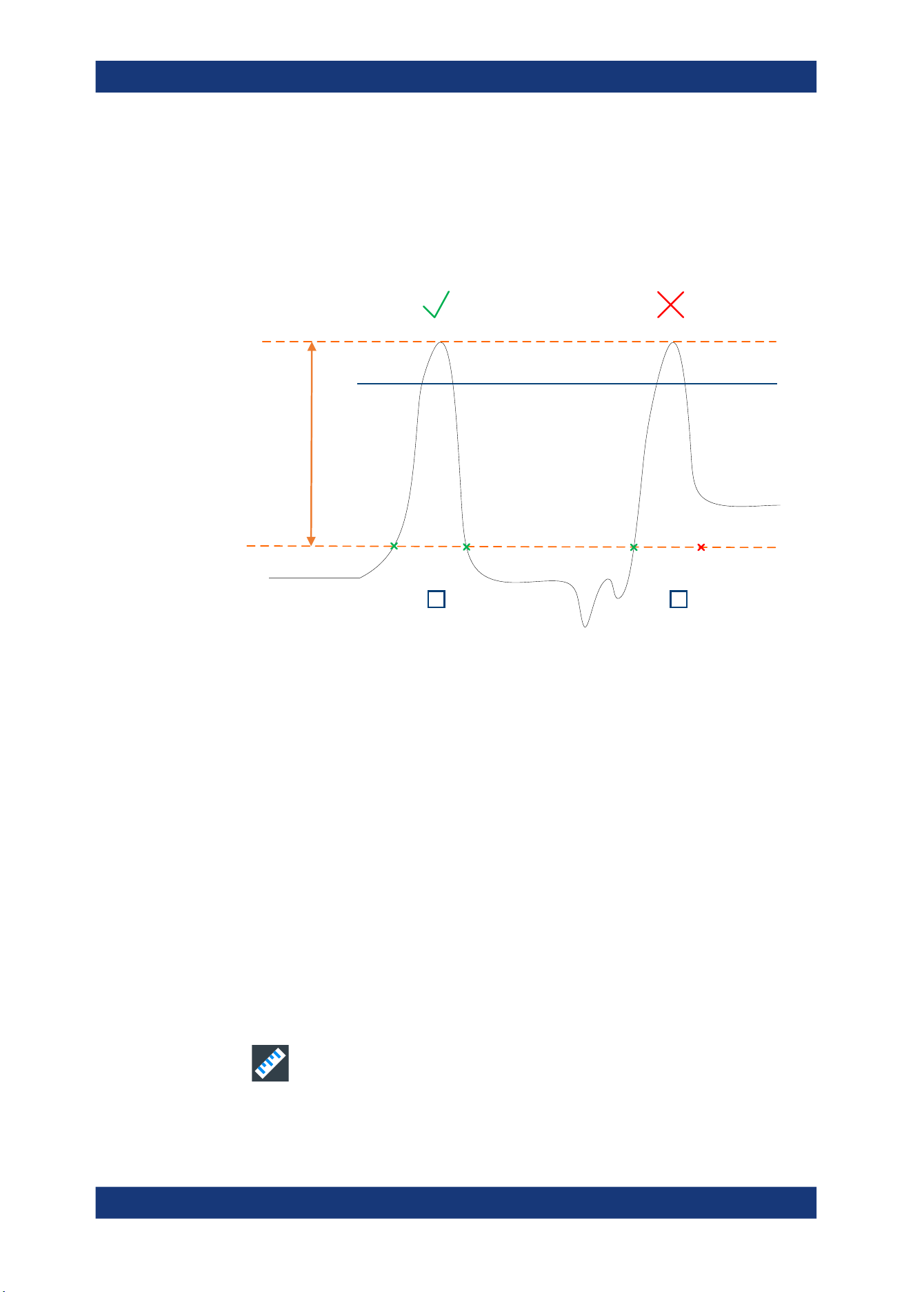
Measurements
R&S
®
MXO 5 Series
193User Manual 1802.3369.02 ─ 02
Example:
In the figure below, 2 peaks are shown, that rise above the defined "Threshold". Peak 1
fulfills the defined "Peak excursion" value and is counted as a peak. Peak 2 does not
fulfill the defined "Peak excursion" value on the right and is not counted as a peak.
Threshold
Peak excursion
1 2
Remote command:
CALCulate:SPECtrum<sp>:PEXCursion on page 594
CURSor<cu>:PEXCursion on page 587
9.2 Automatic measurements
You can perform up to 24 different measurements simultaneously.
There are two methods to start a measurement, each with slightly different effects:
●
Using the "Measure" icon on the toolbar:
See: "To start a measurement using the toolbar icon" on page 193.
●
Pressing the [Measure] key on the front panel, or using the "Measurement" menu.
See: "To configure measurements in the Measurement dialog" on page 194.
To start a measurement using the toolbar icon
1. Tap the "Measure" icon on the toolbar.
The measurement overlay menu opens.
Automatic measurements
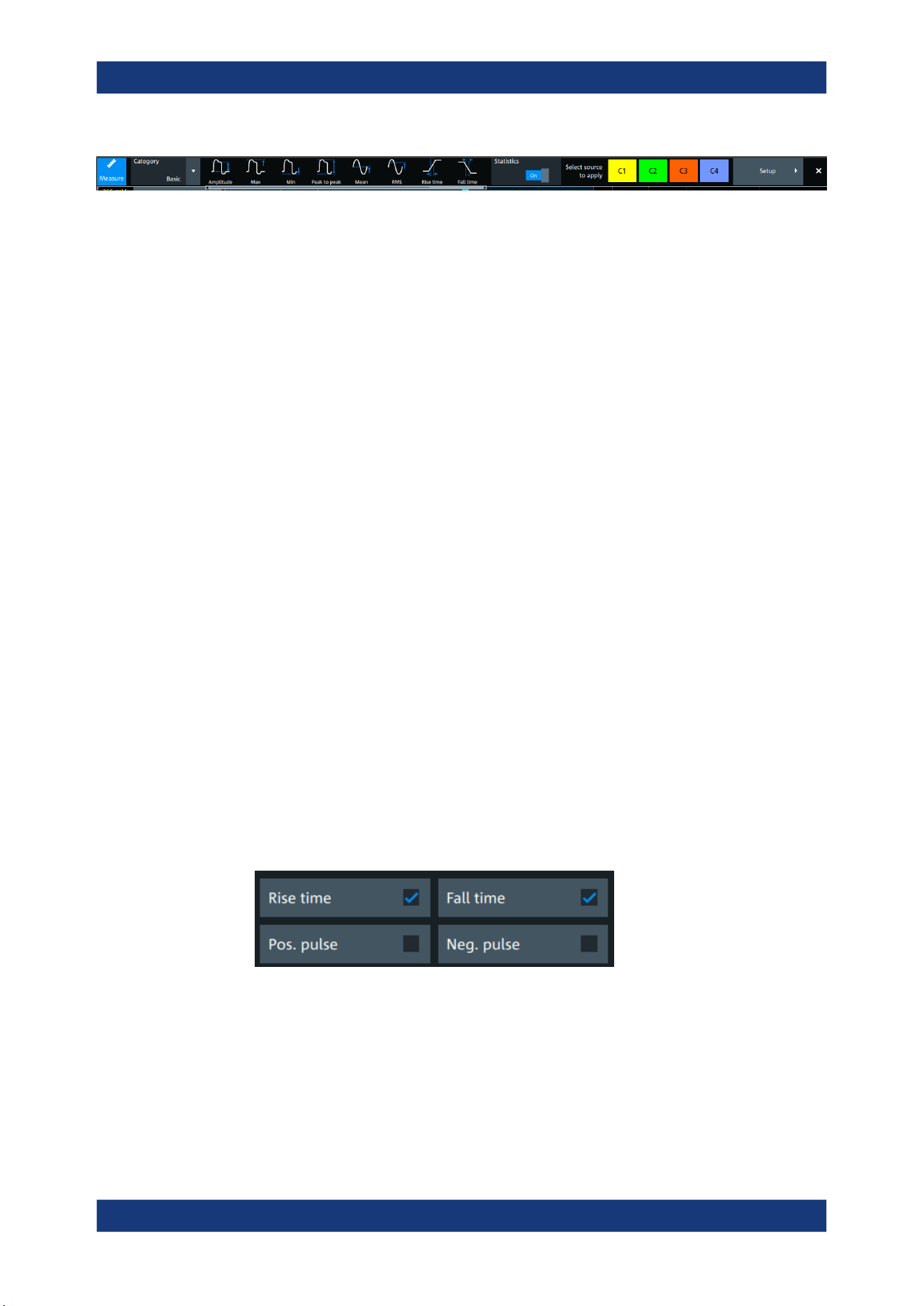
Measurements
R&S
®
MXO 5 Series
194User Manual 1802.3369.02 ─ 02
2. Select the "Category".
3. Tap on the measurements that you want to perform. You can scroll left and right
through the measurement list, to view all available measurements for the selected
"Category".
4. Select the source that you want to apply the measurement on.
5. If needed, click on "Setup" to configure further measurements.
The measurement results are displayed.
To configure measurements in the Measurement dialog
1. Select the waveform on the screen.
2. Press the [Measure] key.
The measurement for the selected waveform is enabled using the next available
measurement configuration. The measurement results are displayed.
To add a new measurement
1. Press the [Measure] key, to open the measurement dialog.
2. In the "Setup" tab, press "Add".
A dialog opens to select the measurements.
3. Select the "Source" for the measurement.
4. Select the "Category" of the measurement that you want to add, e.g. "Horizontal".
All available measurements for this category are displayed. For more details on the
available measurement types, see Chapter 9.2.4, "Measurement types",
on page 202.
5. Tap on a measurement from the list to enable it.
Selected measurements are marked with a blue check mark in their checkbox.
6. The measurements of some categories are listed on several tabs. To switch
between the tabs, press the points at the bottom of the list.
Automatic measurements
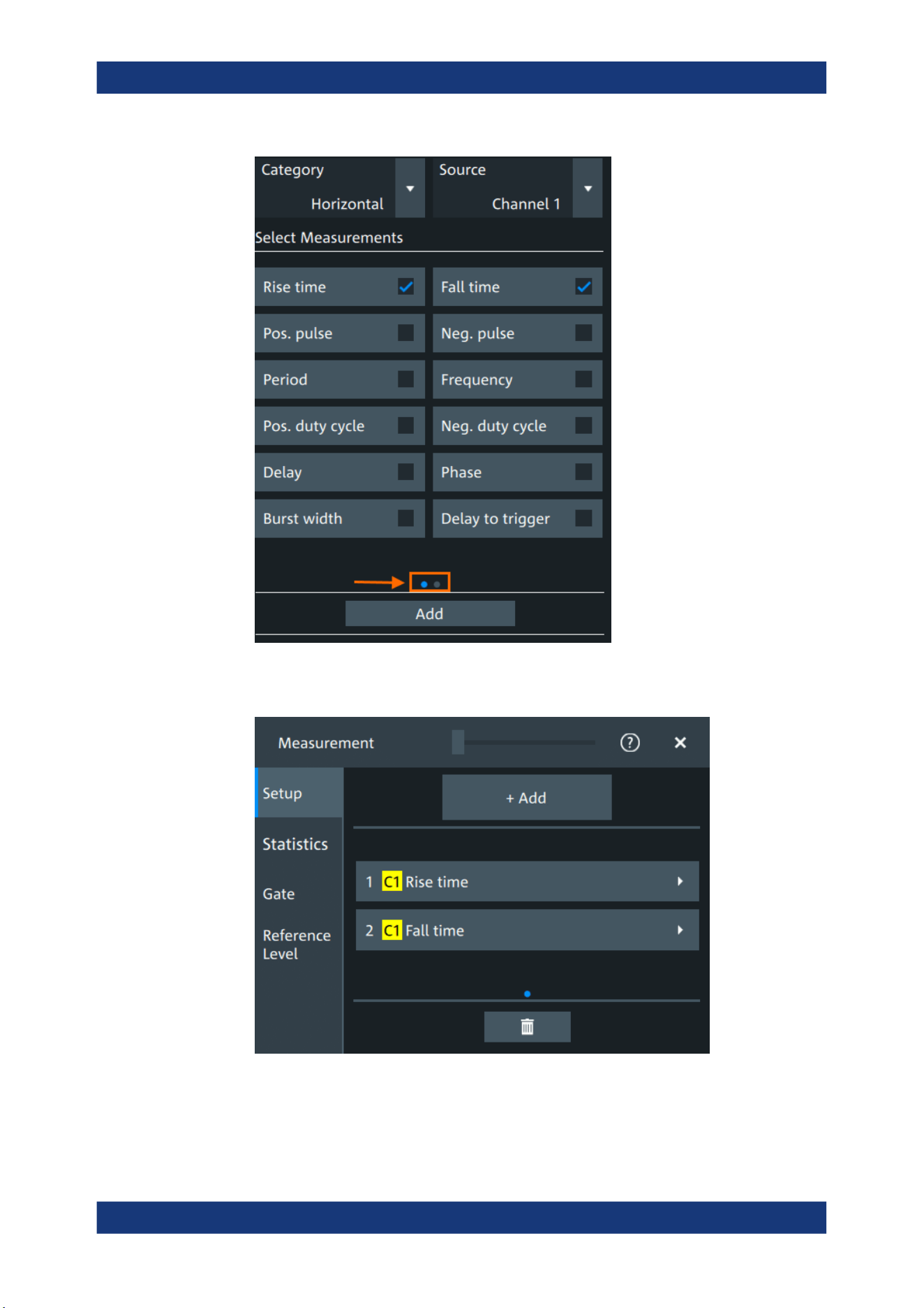
Measurements
R&S
®
MXO 5 Series
195User Manual 1802.3369.02 ─ 02
7. Tap "Add" to add the selected measurements.
All selected measurements are enabled.
To delete a measurement
1. Press the [Measure] key, to open the measurement dialog.
Automatic measurements
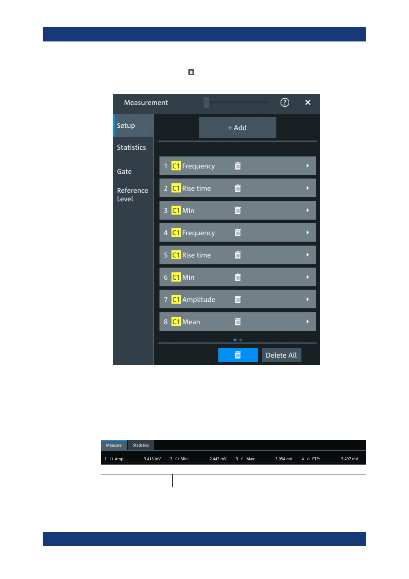
Measurements
R&S
®
MXO 5 Series
196User Manual 1802.3369.02 ─ 02
2.
In the "Setup" tab, press .
A delete icon appears in the selection button of each measurement.
3. Tap on the button of the measurement that you want to delete. Alternatively, tap
"Delete All" to delete all measurements.
9.2.1 Measurement results
The measurement results are shown in a table below the grid.
- No valid waveform is available, for example, if the source waveform is off.
Automatic measurements
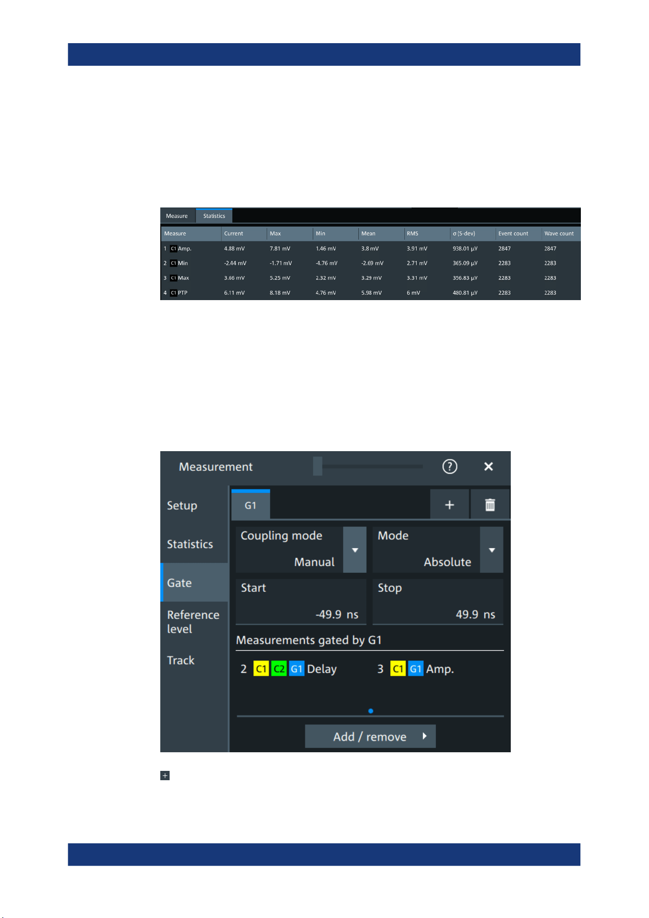
Measurements
R&S
®
MXO 5 Series
197User Manual 1802.3369.02 ─ 02
Statistics
In addition to the current measurement results, you can enable a statistic evaluation. It
returns the current, minimum and maximum measurement values, the average and
standard deviation, and the number of measured waveforms. The results are shown in
a separate tab below the grid. If the cursor measurement is active simultaneously, its
results are shown beside the statistics results.
9.2.2 Gate settings for measurements
Gate areas limit the measurement to a user-defined range of the waveform. The gate
settings are defined on the "Gate" tab.
You can define up to 8 separate gates for the measurement analysis. Then, you assign
the measurements to the gates.
Access: [Measure] > "Gate" tab
Add
Activates a new gate.
Automatic measurements

Measurements
R&S
®
MXO 5 Series
198User Manual 1802.3369.02 ─ 02
Remote command:
GATE<g>:ENABle on page 568
Coupling mode
The gate coupling mode selects how the gate area is defined.
"Manual"
Manually define the gate with a user-defined start and stop values.
"Cursor"
Cursor coupling is available if a cursor is defined. The gate area is
defined by the cursor lines of an active cursor measurement.
If several cursor measurements are enabled, select the "Cursor" to be
used for gating. The start and stop values of the gate are adjusted to
the values of the cursor line positions. The measurement is limited to
the part of the waveform between the cursor lines.
"Zoom"
Zoom coupling is available if a zoom is defined. The gate area is
defined identically to the zoom area - if you change the zoom, the
gate changes as well.
If several zoom diagrams are defined, select the "Zoom" diagram to
be used for gating. The start and stop values of the gate are adjusted
to the values of the zoom positions.
"Spectrum"
Spectrum coupling is available if a spectrum is enabled.
If several spectrums are enabled, select the "Spectrum" diagram to
be used for gating.
Remote command:
GATE<g>:GCOupling on page 568
GATE<g>:CURSor on page 569
GATE<g>:ZDIagram on page 569
Mode
Selects if the gate settings are configured using absolute or relative values.
"Absolute"
The gate is defined by absolute start and stop values with "Start" and
"Stop".
"Relative"
The gate's start and stop values are defined by a percentage of the
value range with "Relative start" and "Relative stop".
Remote command:
GATE<g>:MODE on page 569
GATE<g>:ABSolute:STARt on page 570
GATE<g>:ABSolute:STOP on page 570
GATE<g>:RELative:STARt on page 570
GATE<g>:RELative:STOP on page 570
Measurements gated by G<x>
Displays all active measurements that are limited by the gate.
Remote command:
MEASurement<mg>:GATE on page 563
Add
Opens a dialog to select the measurements to be gated by the active gate. You can
select from the list of all enabled measurements.
Automatic measurements
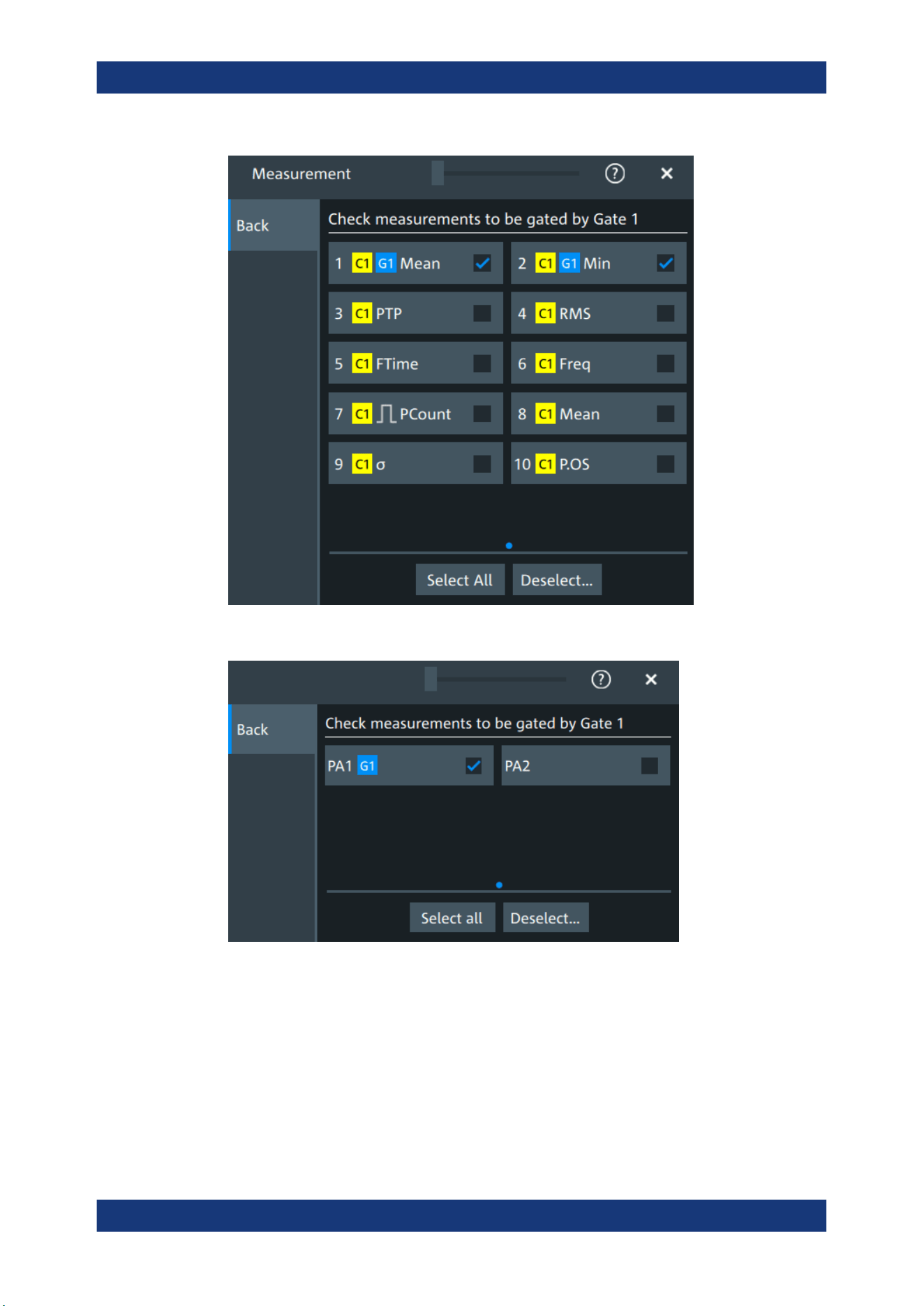
Measurements
R&S
®
MXO 5 Series
199User Manual 1802.3369.02 ─ 02
Figure 9-1: Automatic measurements gate dialog
Figure 9-2: Power quality analysis gate dialog
9.2.3 Reference level
Some measurements require reference levels to obtain the measurement points, e.g.
time measurements or pulse count. You can define 8 sets of reference levels. During
configuration of the measurement, you select which set of reference levels is used.
Automatic measurements
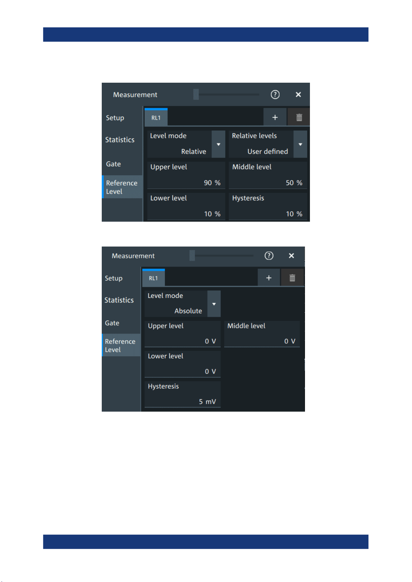
Measurements
R&S
®
MXO 5 Series
200User Manual 1802.3369.02 ─ 02
Access: [Measure] > "Reference level" tab
Figure 9-3: Relative reference level
Figure 9-4: Absolute reference level
RLx
Select the correct refreence level tab before you enter the settings.
You can add up to 8 reference levels.
Remote command:
REFLevel<rl>:ENABle on page 571
Automatic measurements

Measurements
R&S
®
MXO 5 Series
201User Manual 1802.3369.02 ─ 02
Level mode
Defines if the reference level is set in absolute or relative values.
Remote command:
REFLevel<rl>:LMODe on page 571
Absolute Level mode
In the absolute mode, the reference values are set as voltages, in absolute values.
Upper level, Middle level, Lower level ← Absolute Level mode
Sets the low, middle and upper reference signal levels.
Remote command:
REFLevel<rl>:ABSolute:LLEVel on page 572
REFLevel<rl>:ABSolute:MLEVel on page 572
REFLevel<rl>:ABSolute:ULEVel on page 572
Relative Level mode
In the relative mode, the reference values are set as percentages of the signal ampli-
tude.
Relative levels ← Relative Level mode
Selects the lower, middle and upper reference levels, defined as percentages of the
signal amplitude.
Available relative levels:
●
5/50/95
●
10/50/90
●
20/50/80
●
User defined: Enter "Upper level", "Middle level", and "Lower level".
For example, for "5/50/95" the levels are set to the following values:
●
Lower level = 5% of the signal amplitude
●
Middle level = 50% of the signal amplitude
●
Upper level = 95% of the signal amplitude
Remote command:
REFLevel<rl>:RELative:MODE on page 574
Upper level, Middle level,Lower level ← Relative Level mode
Define the reference levels in percent, if "Level mode" is set to "User-defined".
Remote command:
REFLevel<rl>:RELative:LOWer on page 573
REFLevel<rl>:RELative:MIDDle on page 573
REFLevel<rl>:RELative:UPPer on page 574
Hysteresis
Defines a hysteresis for the middle reference level. A rise or fall from the middle refer-
ence value that does not exceed the hysteresis is rejected as noise.
Remote command:
REFLevel<rl>:ABSolute:HYSTeresis on page 571
REFLevel<rl>:RELative:HYSTeresis on page 573
Automatic measurements

Measurements
R&S
®
MXO 5 Series
202User Manual 1802.3369.02 ─ 02
9.2.4 Measurement types
The R&S MXO 5 provides many measurement types to measure time and amplitude
characteristics, and to count pulses and edges.
9.2.4.1 Horizontal measurements (time)
Meas. type Symbol Description/result
Rise Time RTime Rise time of the first rising edge, the time it takes the signal to rise from the lower reference level
to the upper reference level.
Fall Time FTime Fall time of the first falling edge, the time it takes the signal to fall from the upper reference level
to the lower reference level.
Pos. pulse PPuls Duration of the first positive pulse: time between a rising edge and the following falling edge
measured on the middle reference level.
Neg. pulse NPuls Duration of the first negative pulse: time between a falling edge and the following rising edge
measured on the middle reference level.
Period T
in s
Time of the first period, measured on the middle reference level. The measurement requires at
least one complete period of the signal.
Frequency Freq Frequency of the signal, reciprocal value of the measured first period.
Delay Delay Time difference between two slopes of the same or different waveforms, measured on the mid-
dle reference level.
A negative result indicates that the slope of the second source comes before the slope of the
first source.
Phase Phs
in °
Phase difference between two waveforms, measured on the middle reference level.
Burst width Bst Duration of one burst, measured on the middle reference level from the first edge to the last
edge.
Setup
Hold
Setup/Hold time
Setup
Hold
SHT
Setup and Hold time measurements with positive and/or negative clock edge, measured on the
middle reference level.
Setup/Hold ratio SHR Setup/Hold ratio measurement with positive and/or negative clock edge.
Delay to trigger Dly Trg
in s
Time between the trigger point and a selectable edge, measured on the middle reference level.
If the edge is to the left of the trigger (before trigger), the result is negative.
Slew rate rising SrateRis-
ing
Steepness of the first rising edge, measured between the lower and the upper reference levels.
Slewrt = ΔV / Δt
Slew rate falling SrateFal-
ling
Steepness of the first falling edge, measured between the upper and the lower reference levels.
Slewrt = ΔV / Δt
9.2.4.2 Vertical measurements (amplitude)
The unit of most amplitude measurement results depends on the measured source.
Automatic measurements

Measurements
R&S
®
MXO 5 Series
203User Manual 1802.3369.02 ─ 02
Meas. type Symbol Description/result
High High High level of the displayed waveform - the upper maximum of the sample distribution, or the
mean value of the high level of a square wave without overshoot. The measurement requires at
least one complete period of the signal.
Low Low Low level of the displayed waveform - the lower maximum of the sample distribution, or the
mean value of the low level of a square wave without overshoot. The measurement requires at
least one complete period of the signal.
Amplitude Amp Difference between the top level and the base level of the signal. The measurement requires at
least one complete period of the signal.
Max Max Maximum value within the displayed waveform.
Min Min Minimum value within the displayed waveform.
Peak to peak PTP Difference of maximum and minimum values.
Mean Mean Arithmetic average of the complete displayed waveform.
N
k
k
x
N
1
1
Mean
RMS RMS RMS (root mean square) value of the voltage of the complete displayed waveform.
N
k
k
x
N
1
2
1
RMS
σ (S-dev/AC-RMS) σ (S-
dev/AC-
RMS)
Standard deviation of one cycle, usually of the first, left-most signal period.
Crest factor Crest The crest factor is also known as peak-to-average ratio. It is the maximum value divided by the
RMS value of the displayed waveform.
RMS
||Max
Crest
k
x
Pos. Overshoot
Neg. Overshoot
P.OS
N.OS
Overshoot of a square wave after a rising or falling edge. It is calculated from measurement val-
ues top level, base level, local maximum, local minimum, and amplitude.
%100
Amplitude
TopMax
Over
local
%100
Amplitude
Min Base
Over
local
9.2.4.3 Area and cycle measurements
All cycle measurements require that at least one complete period of the signal is
acquired.
Automatic measurements

Measurements
R&S
®
MXO 5 Series
204User Manual 1802.3369.02 ─ 02
Meas. type Symbol Description/result
Area Area Area between the waveform and a reference level (X
Ref
).
Eval
N
i
Ref
Eval
Eval
Ref
Xix
N
T
A
1
)(
T
Eval
: Evaluation time, time of a full waveform or limited by a gate
Cycle area CArea Area between the waveform and a reference level measured for one period, see also "Area" mea-
surement.
Pos duty cycle PDCyc Width of the first positive pulse in relation to the period in %.
%100
Period
PosPulse
PosCyc
T
T
R
Neg duty cycle NDCyc Width of the first negative pulse in relation to the period in %.
%100
Period
NegPulse
NegCyc
T
T
R
Cycle mean CMean Mean value of one cycle
Cycle RMS CRMS RMS (root mean square) value of one cycle
Cycle σ(S-dev) Cycσ Standard deviation of one cycle
Cycle max CMax Maximum value of one cycle
Cycle min CMin Minimum value of one cycle
Cycle peak to
peak
CPTP Peak-to-peak value of one cycle: the difference of CMax and CMin
9.2.4.4 Counting
Meas. type Symbol Description/result
Pulse count PCount The number of positive or negative pulses of the waveform, or of both positive and negative pul-
ses.
The mean value of the signal is determined. If the signal passes the mean value, an edge is coun-
ted. A positive pulse is counted if a rising edge and a following falling edge are detected. A nega-
tive pulse is counted if a falling edge and a following rising edge are detected.
Edge count EdCo The number of positive or negative edges, or of both positive and negative edges.
The instrument determines the mean value of the signal and counts an edge every time the signal
passes the mean value.
9.2.5 Settings for measurements
In the "Measurement" dialog, you can enable measurement and define their settings.
Automatic measurements
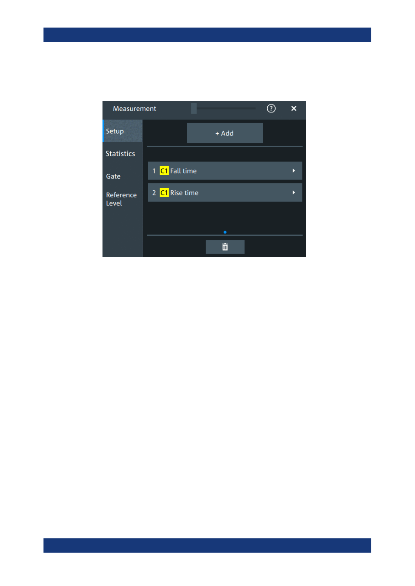
Measurements
R&S
®
MXO 5 Series
205User Manual 1802.3369.02 ─ 02
9.2.5.1 Setup tab
Access: "Menu" > "Measurement" > "Setup" tab.
Add
Opens a dialog to select the measurements.
Automatic measurements
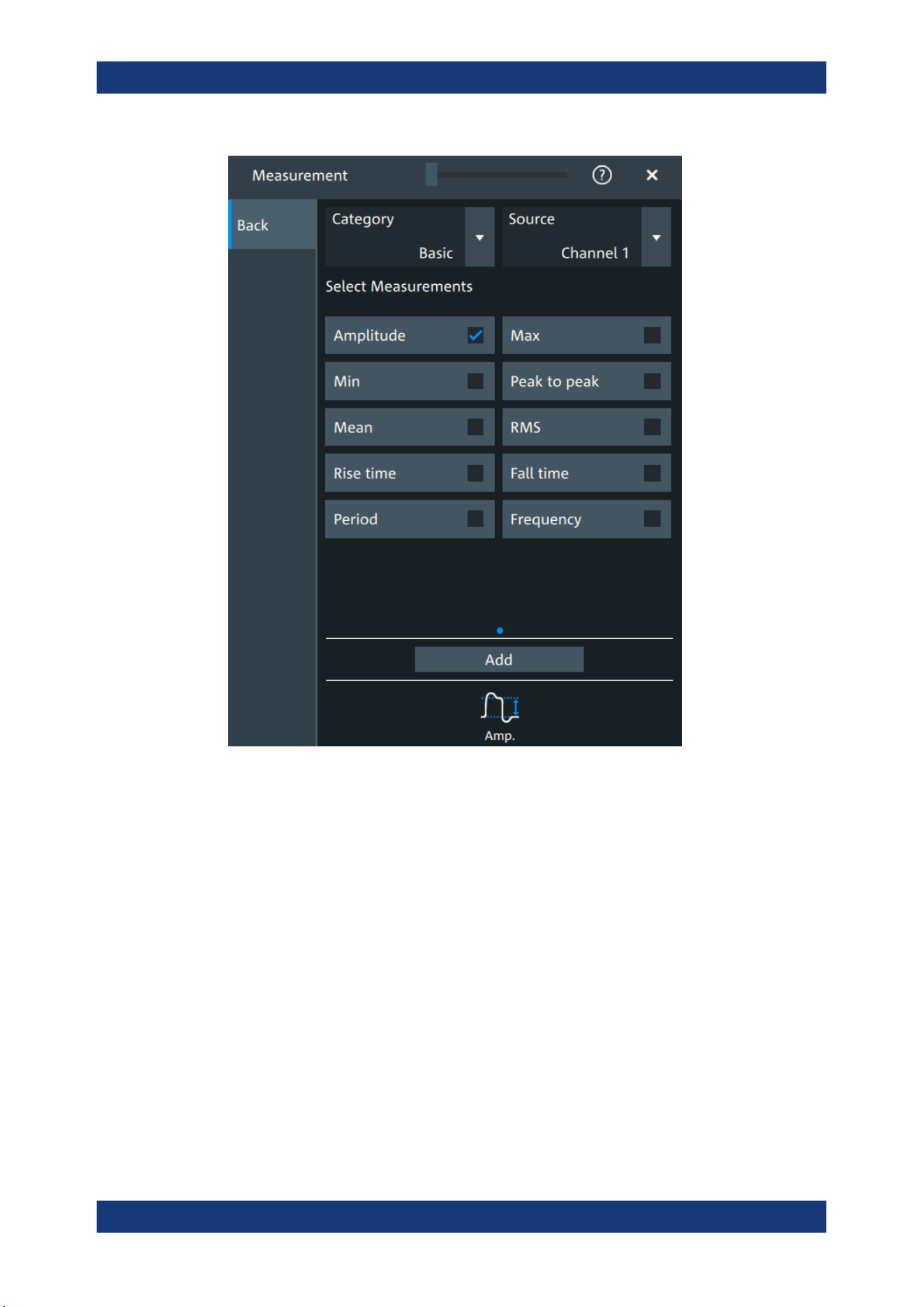
Measurements
R&S
®
MXO 5 Series
206User Manual 1802.3369.02 ─ 02
Category ← Add
Selects the measurement category. Some measurements are listed in more than one
category.
For an overview of the available categories and measurements, see Chapter 9.2.4,
"Measurement types", on page 202.
Source ← Add
Sets the source of the measurement.
Remote command:
MEASurement<mg>:SOURce on page 558
Delete icon
Enables the removal of measurements. You can delete a single measurement by tap-
ping on the delete icon next to it.
You can also delete all current measurements with "Delete All".
Automatic measurements
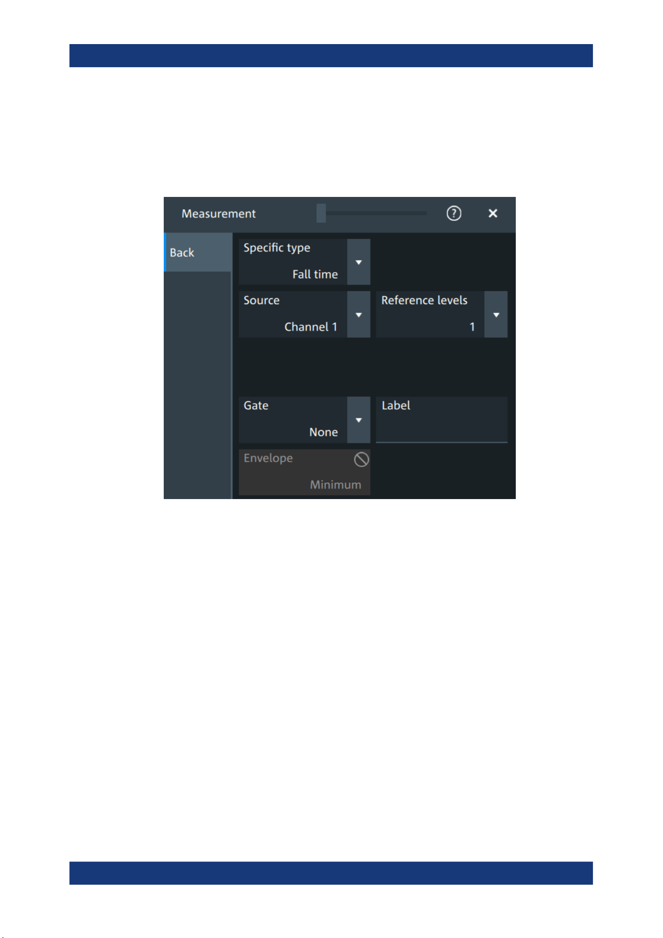
Measurements
R&S
®
MXO 5 Series
207User Manual 1802.3369.02 ─ 02
9.2.5.2 Measurement type specific settings
You can define additional parameters for some measurements.
Access: "Menu" > "Measurement" > "Setup" tab > Add measurement > Select mea-
surement
Specific type
Selects the type of measurement that you want to define the settings for.
Source
Sets the source of the measurement.
Remote command:
MEASurement<mg>:SOURce on page 558
Reference levels
Selects the set of reference levels that is used for the measurement (RL1, RL2...), and
for the selected source. Each source of the measurement can have its own reference
level set.
Only the numbers of defined reference level sets are listed. Define the reference level
set before you select it, see Chapter 9.2.3, "Reference level", on page 199.
Remote command:
MEASurement<mg>:REFLevel<sc>:REFerence on page 563
Gate
Selects the gate that is used for limiting the measurement range. Define a gate before
you select it, see Chapter 9.2.2, "Gate settings for measurements", on page 197.
Automatic measurements

Measurements
R&S
®
MXO 5 Series
208User Manual 1802.3369.02 ─ 02
Remote command:
MEASurement<mg>:GATE on page 563
Label
Adds a user-defined label to the measurement.
Envelope
This setting is only available for measurements on envelope waveforms, see Acquisi-
tion mode.
"Both"
The upper and the lower envelope are used in measurements. For
time measurements, the averages of min and max values are used,
that is, the measurement is performed on the average waveform built
from the upper and lower envelope.
"Maximum"
Measurements are performed on the upper envelope.
"Minimum"
Measurements are performed on the lower envelope.
Remote command:
MEASurement<mg>:ENVSelect on page 559
Pulse count
Available, if "Specific type" is set to "Pulse train".
Sets the number N of positive pulses for the "Pulse train" measurement. This measure-
ment measures the duration of N positive pulses from the rising edge of the first pulse
to the falling edge of the N-th pulse.
Remote command:
MEASurement<mg>:AMPTime:PTCount on page 561
Pulse slope
Available, if "Specific type" is set to "Pulse count".
Sets the first slope of the pulses to be counted.
"Positive"
Positive pulses are counted.
"Negative"
Negative pulses are counted.
"Either"
Both positive and negative pulses are counted.
Remote command:
MEASurement<mg>:AMPTime:PSLope on page 561
Edges slope
Available, if "Specific type" is set to "Edge count" or "Delay to trigger".
Sets the edge direction to be used for delay measurement: positive, negative, or either
edge.
Remote command:
MEASurement<mg>:AMPTime:ESLope on page 560
Automatic measurements
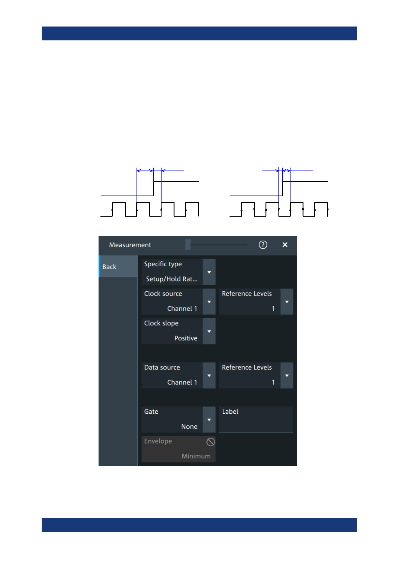
Measurements
R&S
®
MXO 5 Series
209User Manual 1802.3369.02 ─ 02
Setup/Hold time measurement
Setup/Hold measurements analyze the relative timing between two signals: a data sig-
nal and the synchronous clock signal. Setup time is the time that the data signal is
steady before clock edge - the time between a data transition and the next specified
clock edge. Hold time is the time that the data signal is steady after clock edge - the
time between a data transition and the previous specified clock edge.
"Setup/Hold time" measures and displays the setup and hold durations. "Setup/Hold
ratio" measurements return the ratio of the setup time to the sum of hold and setup
time: T
Setup
/
(T
Setup
+
T
Hold
).
The clock edge can be defined, the polarity of the data signal does not matter.
SetupHold Setup
Hold
Clock
Data
Clock slope = Positive Clock slope = Either
Clock source ← Setup/Hold time measurement
Sets the waveform used as clock in the setup/hold measurement.
Automatic measurements
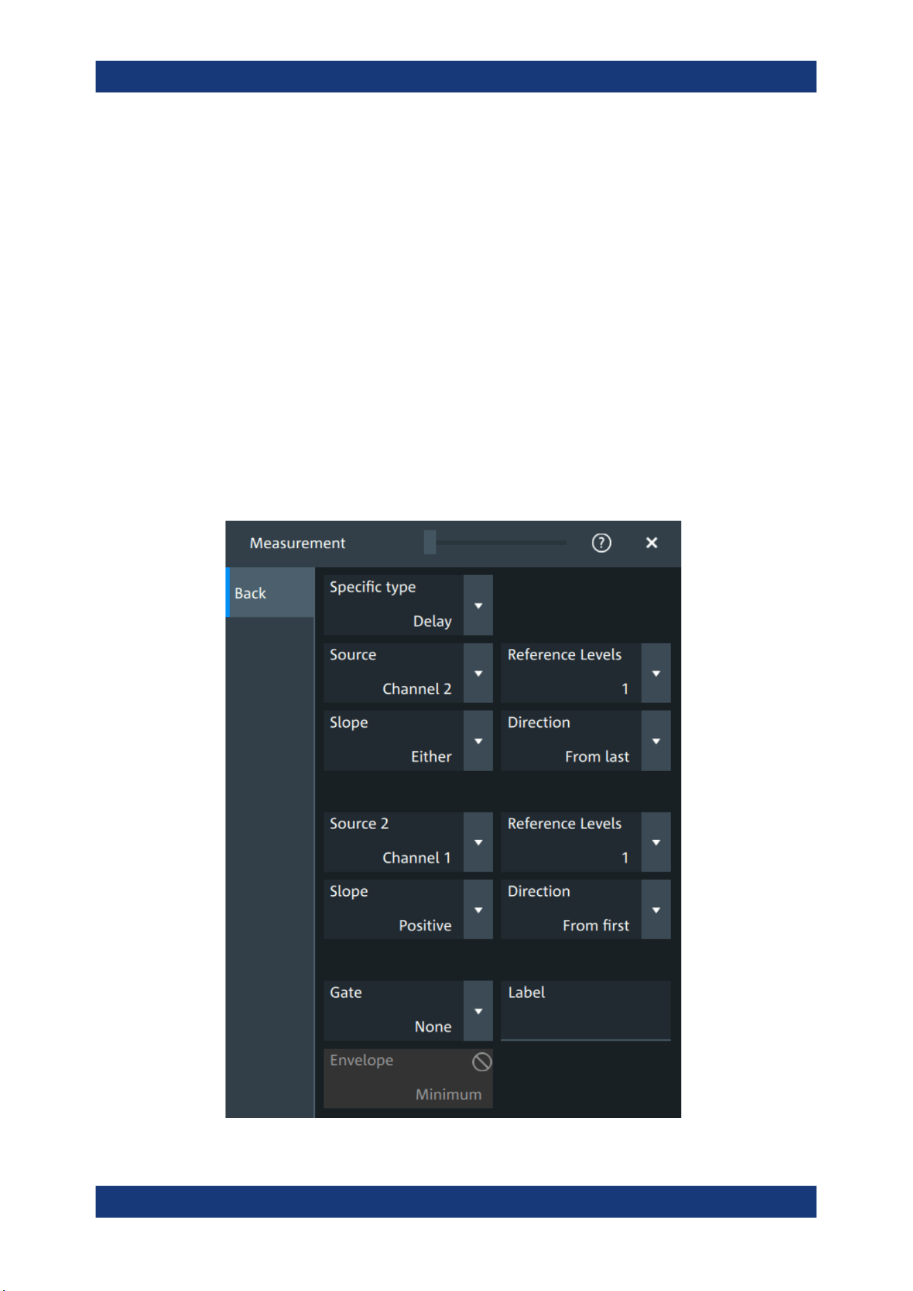
Measurements
R&S
®
MXO 5 Series
210User Manual 1802.3369.02 ─ 02
Remote command:
MEASurement<mg>:SSRC on page 559
Clock slope ← Setup/Hold time measurement
Sets the edge of the clock from which the setup and hold times are measured: positive,
negative, or either of them. If "Either" is selected, the clock edges next to the data edge
are considered regardless of the clock slope.
Remote command:
MEASurement<mg>:AMPTime:CSLope on page 560
Data source ← Setup/Hold time measurement
Sets the source for the data signal.
Delay measurement
The specific settings for delay measurement allow you to measure the time between
any two slopes at any reference level. Therefore, the reference levels and the slopes
must be defined for each source individually. The measurement result is negative if the
edge of the second source comes before the edge of the first source.
Automatic measurements
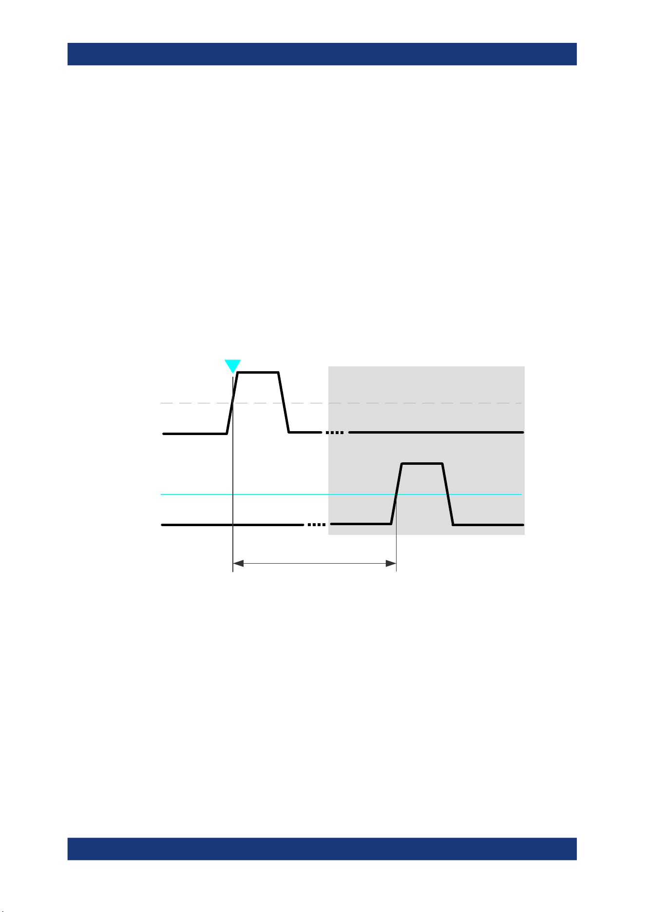
Measurements
R&S
®
MXO 5 Series
211User Manual 1802.3369.02 ─ 02
Slope ← Delay measurement
Sets the edge of each source, between which the delay is measured: positive, nega-
tive, or either of them.
Remote command:
MEASurement<mg>:AMPTime:DELay<n>:SLOPe on page 562
Direction ← Delay measurement
Selects the direction for counting slopes for each source: from the beginning of the
waveform, or from the end.
Remote command:
MEASurement<mg>:AMPTime:DELay<n>:DIRection on page 561
Delay to trigger measurement settings
Delay to trigger measures the time between the trigger point and the following slope of
a waveform. The delay between the trigger and the slope can be high compared to the
accuracy of the acquisition, and the trigger point can even be outside of the current
acquisition.
Trigger
source
Measurement
source
Trigger
level
Reference
level
Slope
Trigger
event
Delay to trigger
To configure the trigger conditions, use the trigger setup.
"Edges slope"
Sets the edge direction to be used for delay measurement: positive,
negative, or either edge.
Remote command:
MEASurement<mg>:AMPTime:DTOTrigger<n>:SLOPe on page 562
9.2.6 Statistics
Access: "Menu" > "Measurement" > "Statistics" tab.
Automatic measurements
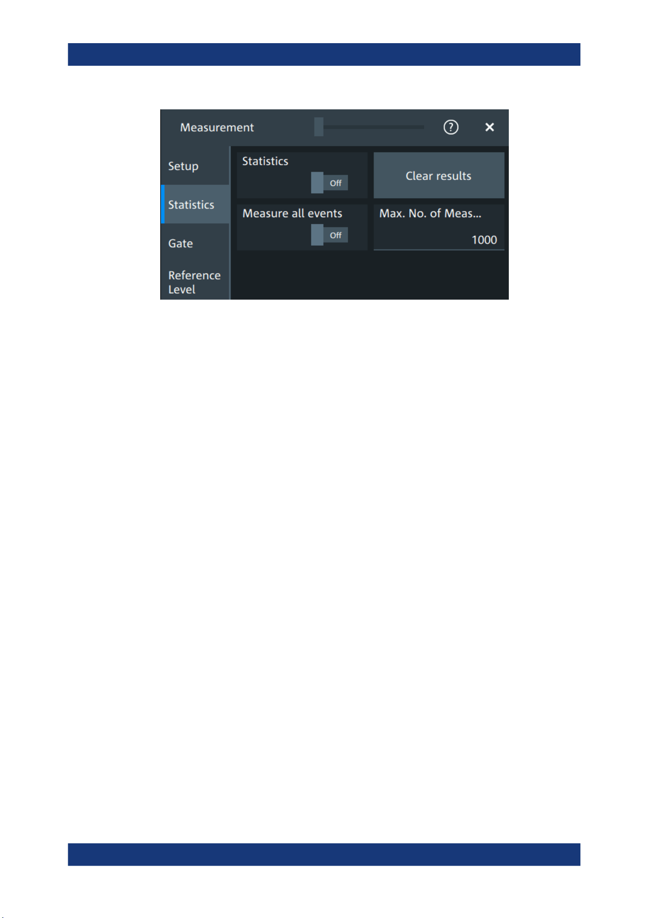
Measurements
R&S
®
MXO 5 Series
212User Manual 1802.3369.02 ─ 02
In addition to the current measurement results, you can enable a statistical evaluation.
It returns the current, minimum and maximum measurement values, the average and
standard deviation, and the number of measured waveforms. The results are shown in
a separate tab below the grid. If the cursor measurement is active simultaneously, its
results are shown beside the statistics results.
Statistics
Activates or deactivates the statistical evaluation for the measurement.
Remote command:
MEASurement<mg>:STATistics[:ENABle] on page 567
Clear results
Deletes the statistical results for all measurements, and starts a new statistical evalua-
tion if the acquisition is running.
Remote command:
MEASurement<mg>:STATistics:ARESet on page 566
Measure all events
Normally, only one measurement is performed for each acquired waveform to get best
performance. If "Measure all events" is enabled, more than one result is taken from
one acquired waveform and the results are included in evaluation. For example, the
rise time is measured on all pulses in the waveform, not only on the first.
The result table shows only the first result of the waveform, the following results are
used only for evaluation. The number of considered results can be restricted: see Max.
No. of events.
Measuring all events is useful when calculating statistics.
The setting affects all measurements, it is a global setting. However, if a track is
enabled for a selected measurement, all results are considered for this measurement,
independent from the global setting.
Remote command:
MEASurement<mg>:MULTiple on page 567
Automatic measurements
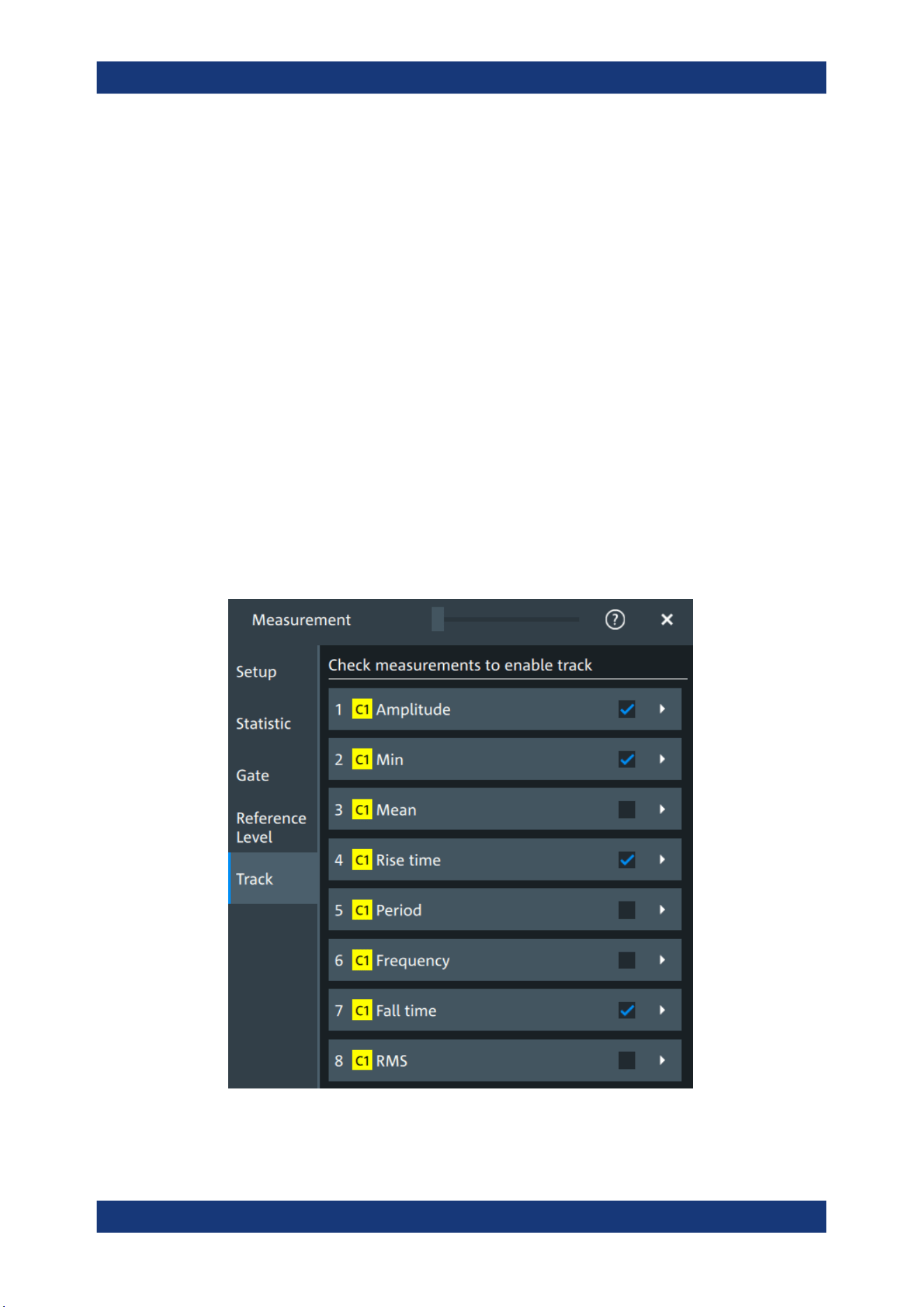
Measurements
R&S
®
MXO 5 Series
213User Manual 1802.3369.02 ─ 02
Max. No. of events
Sets the maximum number of measured events per acquisition.
Remote command:
MEASurement<mg>:MNOMeas on page 567
9.2.7 Track
A track shows the measurement results over time for an acquired waveform. The track
is the graphical interpretation of all measurement values of a single acquisition. Fur-
thermore, the track reveals trends of change in the analysis and preserves the timing
relationship of the measurement results to the signal.
Tracks can be enabled for each active measurement. Enabling the track also enables
"Measure all events" for the selected measurement.
To analyze tracks, you can use cursor measurements, zoom, mathematics and spec-
trum.
9.2.7.1 Track settings
Access: "Menu" > "Measurement" > "Track" tab.
Figure 9-5: Measurement selection for tracks
Automatic measurements
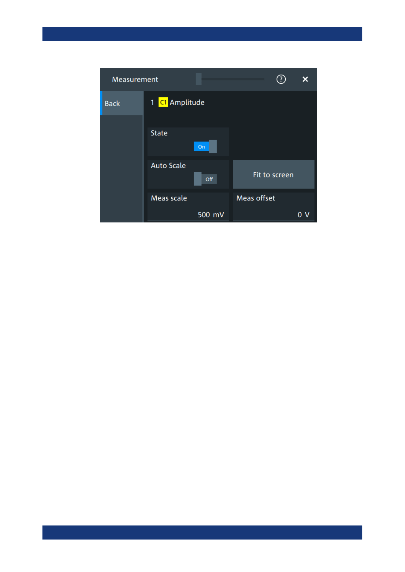
Measurements
R&S
®
MXO 5 Series
214User Manual 1802.3369.02 ─ 02
Figure 9-6: Track settings
Check measurements to enable track
The list shows all active measurements. Select the check square of a measurement to
enable the track for this measurement. Tap the button to open the track settings.
State
Enables or disables the track for the selected measurement.
Enabling the track also enables "Measure all events" for the selected measurement.
Remote command:
MEASurement<mg>:TRACk[:STATe] on page 575
Auto Scale
Performs an automatic scaling whenever the track does not fit in the diagram during
the measurement period.
Remote command:
MEASurement<mg>:TRACk:CONTiunous on page 575
Fit to screen
Sets the vertical scale and the offset of the track, so that the complete height of the
diagram is used.
Remote command:
MEASurement<mg>:TRACk:AUTO on page 575
Meas scale
Defines the vertical scale of the track diagram. If "Auto Scale" is on, the current scale
value is displayed.
You can also select the track waveform and use the vertical [Scale] knob to change the
scale.
Automatic measurements
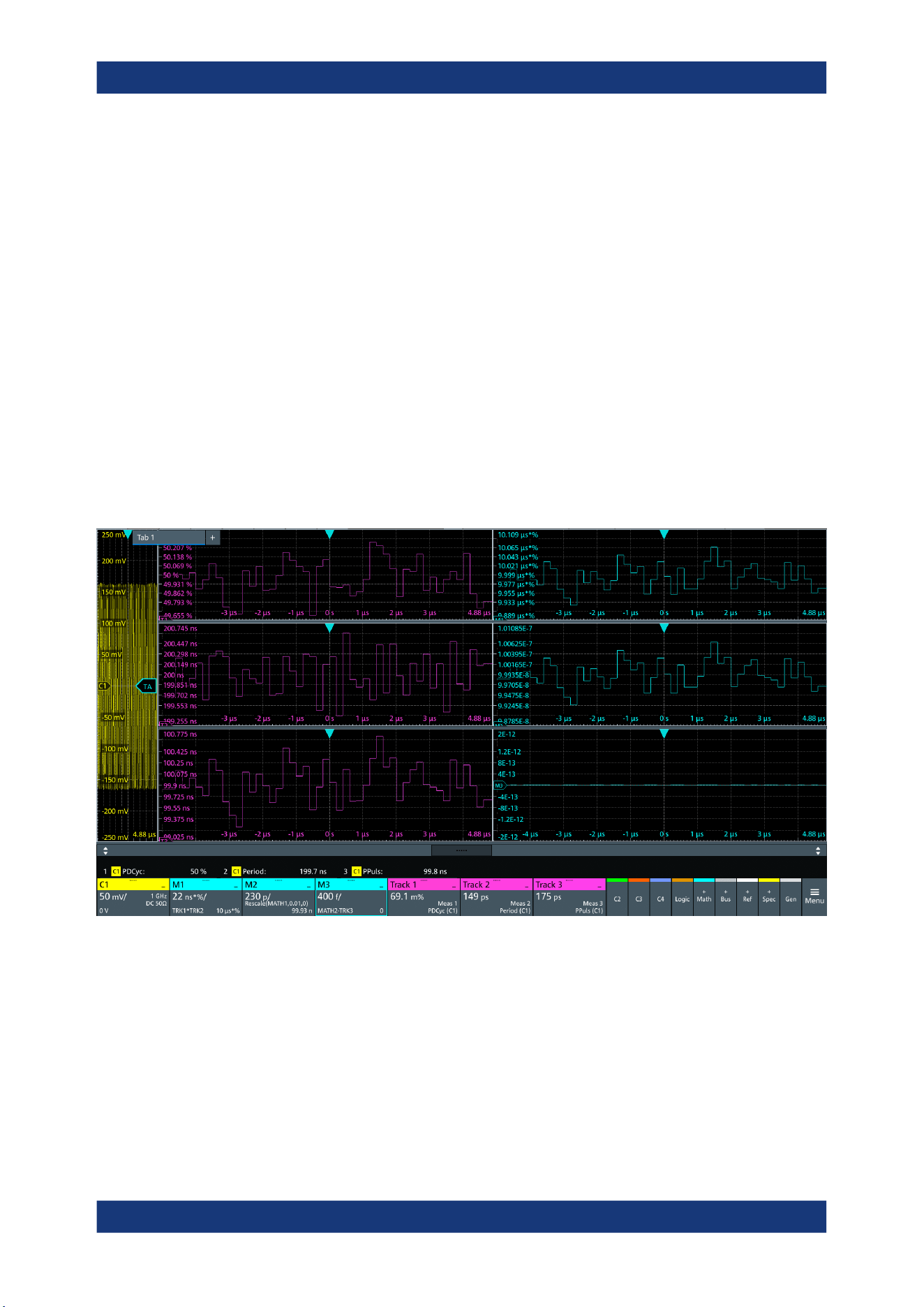
Measurements
R&S
®
MXO 5 Series
215User Manual 1802.3369.02 ─ 02
Remote command:
MEASurement<mg>:TRACk:SCALe on page 576
Meas offset
Defines the offset of the track waveform. If "Auto Scale" is on, the current offset value
is displayed.
You can also select the track waveform and use the vertical [Position] knob to change
the offset.
Remote command:
MEASurement<mg>:TRACk:OFFSet on page 576
9.2.7.2 Examples of track usage
The examples in this section provide ideas on how you can use tracks for waveform
analysis.
Tracks with math functions
Figure 9-7: Tracks used in math functions
The example is set up as follows:
●
Waveform on channel 1
●
3 measurements on C1: positive duty cycle, period and positive pulse width
●
Enable track for each measurement: Track 1 (positive duty cycle), Track 2 (period),
Track 3 (positive pulse width)
●
Math1 = Trk1 * Trk2
●
Math2 = Math1 / 100
Automatic measurements
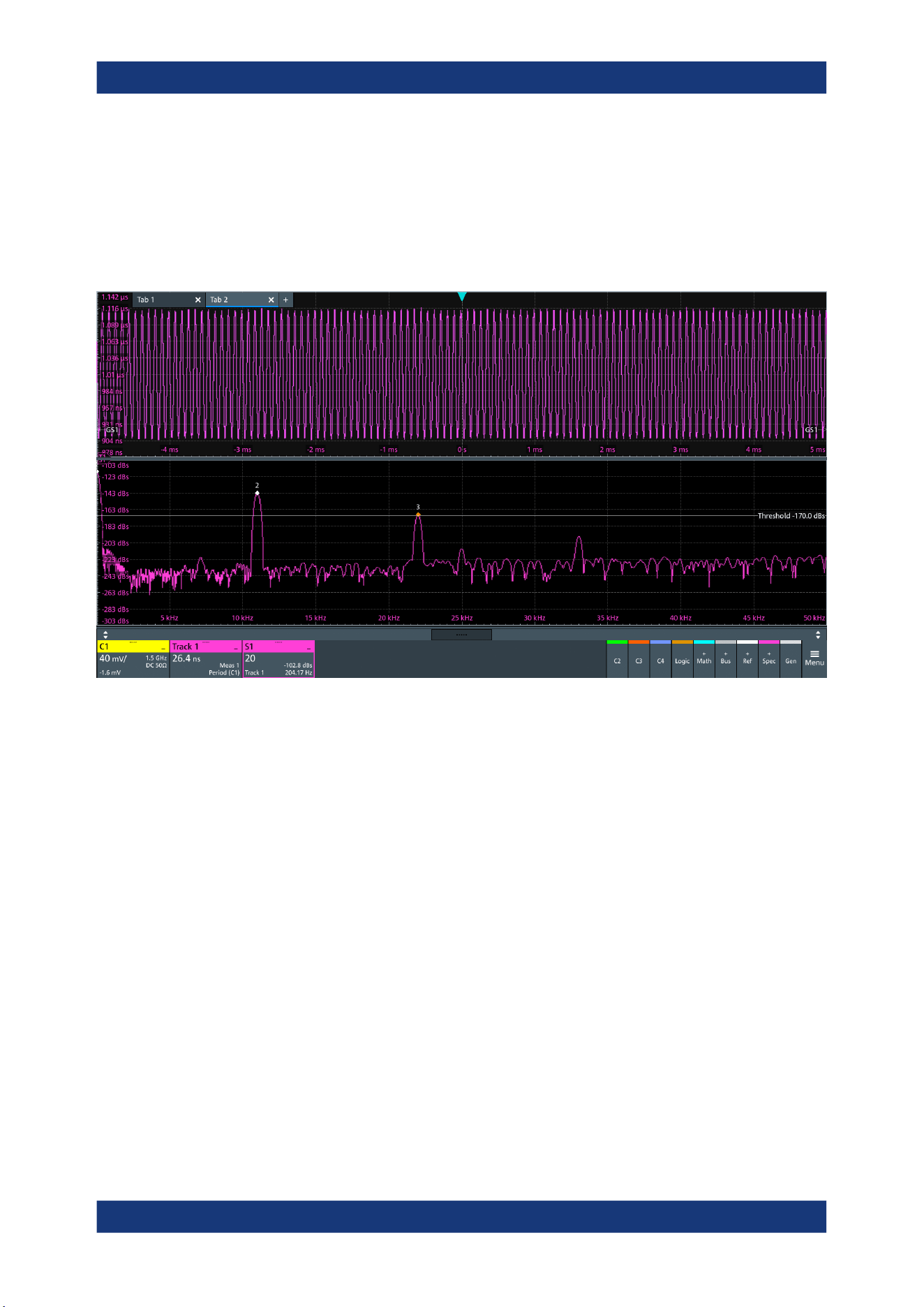
Measurements
R&S
®
MXO 5 Series
216User Manual 1802.3369.02 ─ 02
Expected values: Period * Pos. duty cycle / 100 = Positive pulse width, i.e. Math2 =
Trk3
●
Math3 = Math2 - Trk3
Expected values = 0
Spectrum on track
Figure 9-8: Track and spectrum on track, C1 is not in diagram
The example is set up as follows:
●
Waveform on channel 1
●
Period measurement on C1
●
Enable track for the period measurement: Track 1
●
Spectrum with "Source" = Track 1
●
Enable "PeakList" > "Peak on waveform"
Automatic measurements
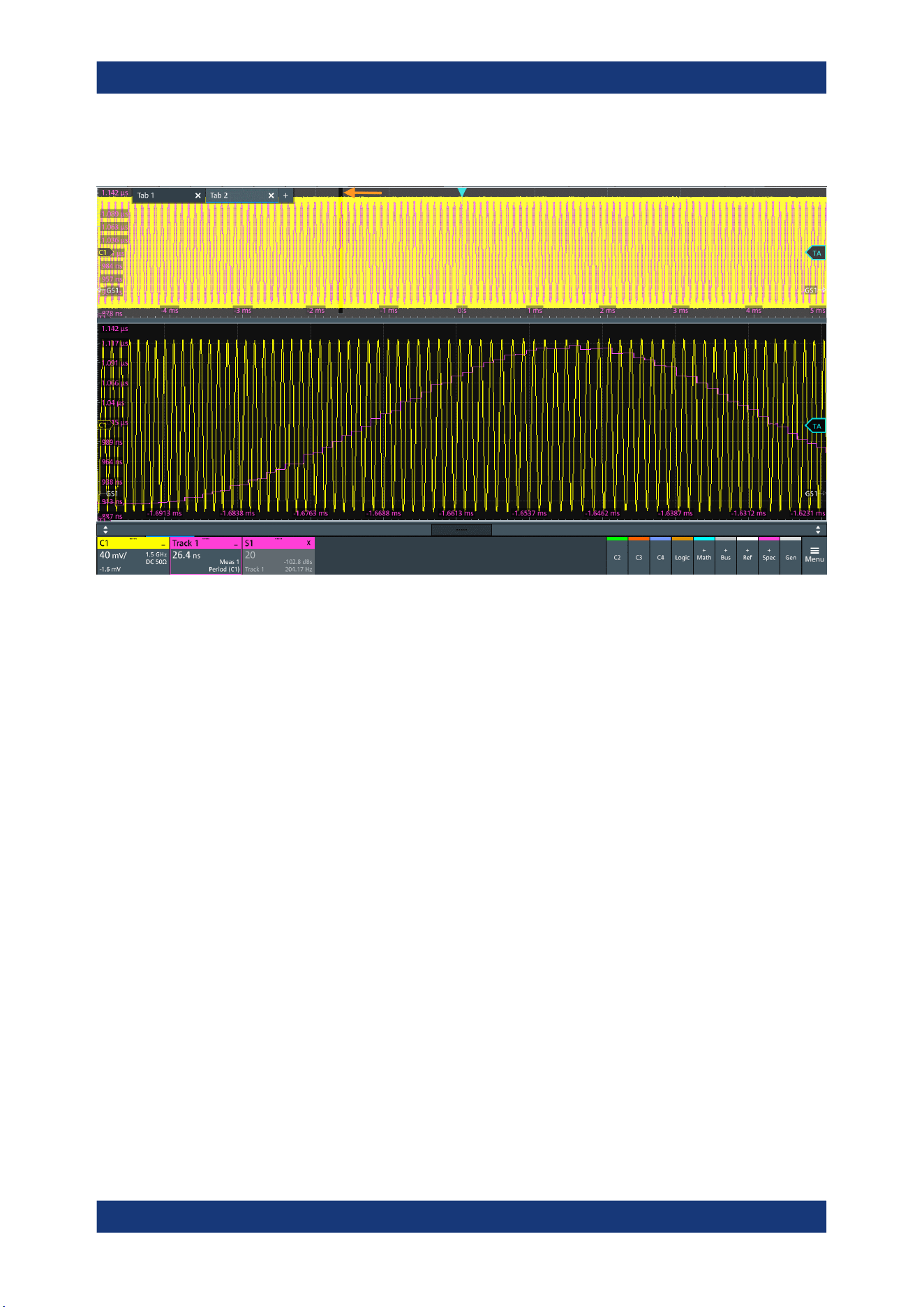
Measurements
R&S
®
MXO 5 Series
217User Manual 1802.3369.02 ─ 02
Zoom on track
Figure 9-9: Track and C1 in the upper diagram, zoom below
The example is set up as follows:
●
Waveform on channel 1
●
Period measurement on C1
●
Enable track for the period measurement: Track 1
●
Drag and drop the track on the channel waveform
●
Create zoom
Automatic measurements
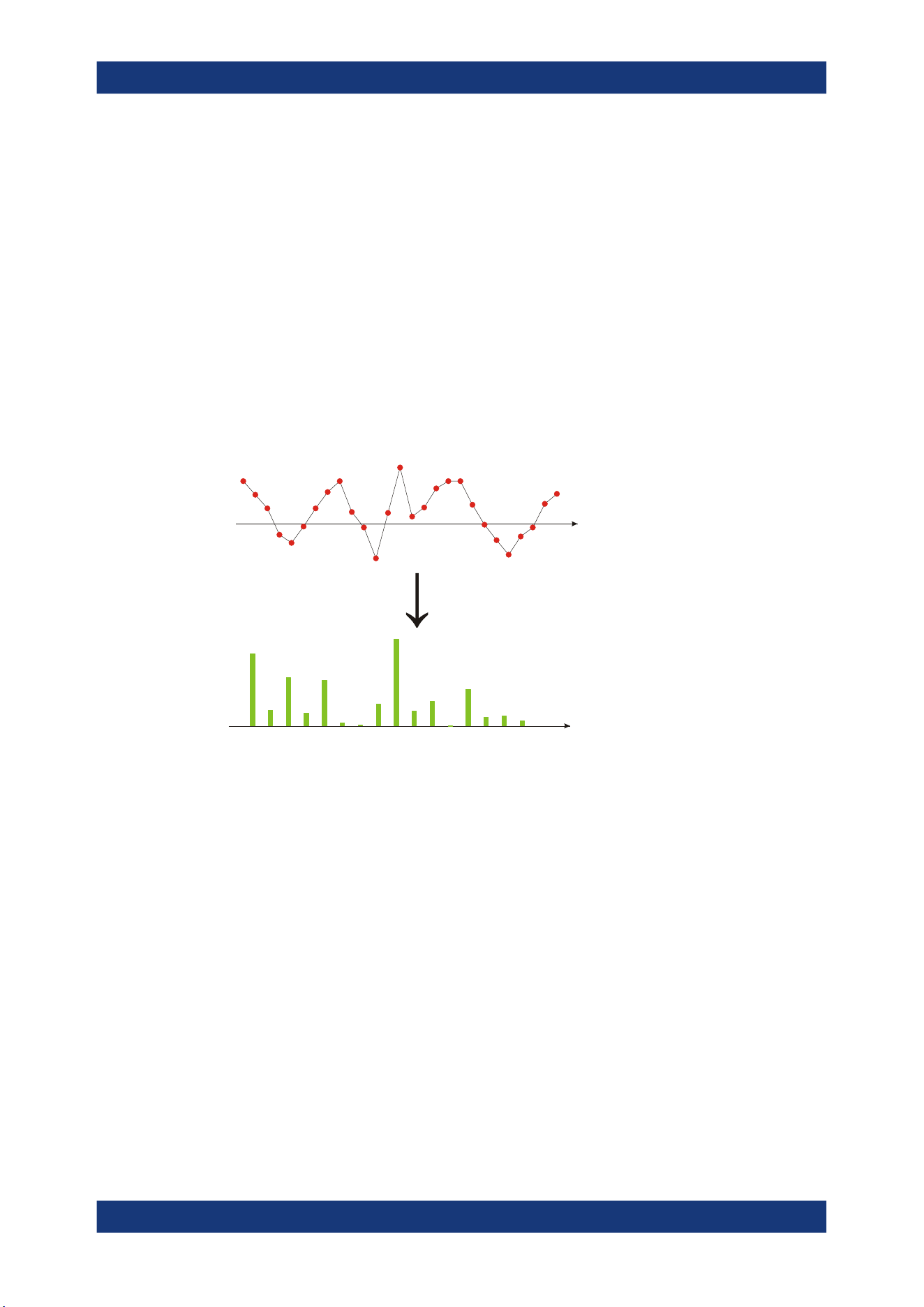
Spectrum analysis
R&S
®
MXO 5 Series
218User Manual 1802.3369.02 ─ 02
10 Spectrum analysis
The R&S MXO 5 provides an easy way to set up a spectrum analysis. The spectrum
settings are independent of the time domain settings but the time and frequency
domains are time-correlated.
10.1 Fundamentals of spectrum analysis
During spectrum analysis, a signal in the time domain is converted to a spectrum of
frequencies. As a result, either the magnitude or the phase of the determined frequen-
cies can be displayed. Spectrum analysis can be restricted to an extract of the original
time base, and the results display can be restricted to a specified frequency range.
t[s]
FFT
f[Hz]
Window functions
Each frame is multiplied with a specific window function after sampling in the time
domain. Windowing helps minimize the discontinuities at the end of the measured sig-
nal interval and thus reduces the effect of spectral leakage, increasing the frequency
resolution.
There are several window functions that can be used in FFT analysis. Each of the win-
dow functions has specific characteristics, including some advantages and some trade-
offs. Consider these characteristics carefully to find the optimum solution for the mea-
surement task.
For details, see "Window type" on page 224.
Gating functions
You can restrict the time base of the input signal for which spectrum analysis is to be
performed. You can define start and stop times for the time base extract.
Fundamentals of spectrum analysis
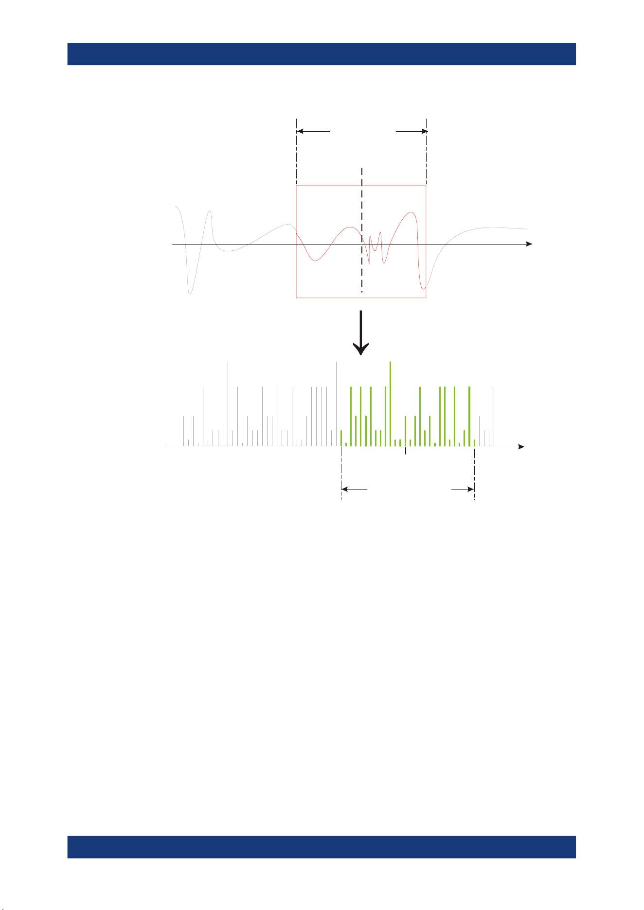
Spectrum analysis
R&S
®
MXO 5 Series
219User Manual 1802.3369.02 ─ 02
t[s]
Gate
Gate position
Gate length
f[Hz]
FFT
Center frequency
Frequency span
Restricting the result range
You can restrict the results of the spectrum analysis to a specified frequency range.
The frequency range can be defined in two ways:
●
Define a center frequency and frequency span
●
Define start and stop frequencies
Dependencies between spectrum parameters
Spectrum analysis in the R&S MXO 5 is highly configurable. Several parameters,
including the resolution bandwidth, frequency span and center frequency, can be
defined according to your requirements. Note, however, that several parameters are
correlated and not all can be configured independently of the others.
The resolution bandwidth defines the minimum frequency separation at which the
individual components of a spectrum can be distinguished. Small values result in high
precision, as the distance between two distinguishable frequencies is small. Higher val-
ues decrease the precision, but increase measurement speed.
The minimum achievable RBW depends on the integration time which is equivalent to
the number of samples available for calculation. If a higher spectral resolution is
Fundamentals of spectrum analysis
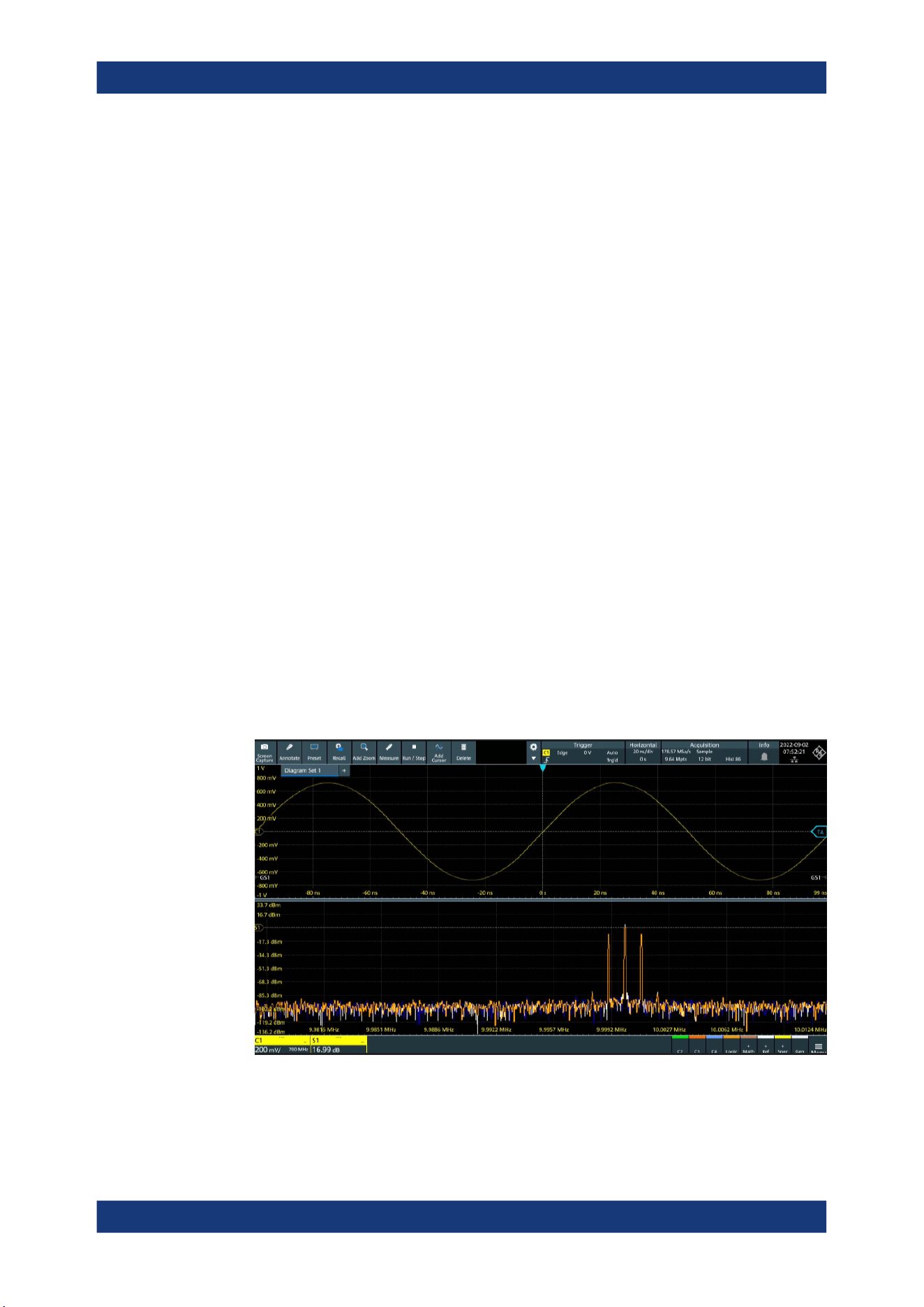
Spectrum analysis
R&S
®
MXO 5 Series
220User Manual 1802.3369.02 ─ 02
required, the number of samples must be increased by using a higher sample rate or
longer record length. To simplify operation, some parameters are coupled and auto-
matically calculated, such as record length and RBW.
The frequency span and center frequency define the start and stop frequency of the
spectral diagram. By default, a suitable frequency range according to the resolution
bandwidth is selected, in respect to performance and precision. Span and RBW set-
tings are coupled, so that the parameters can be adjusted automatically as necessary.
With a Span/RBW ratio of 100 and a screen resolution of 1000 pixels, each frequency
in the spectrum is displayed by 10 pixels. A span/RBW ratio of 1000 provides the high-
est resolution. For full flexibility, the span/RBW coupling can also be disabled. Note,
however, that a higher span/RBW ratio (i.e. low RBW values and large frequency
spans) result in large amounts of data and extend the duration of the calculation.
10.2 Configuring spectrum waveforms
During spectrum analysis, a signal in the time domain is converted to a spectrum of
frequencies. A basic spectrum waveform can be displayed quickly. By defining addi-
tional parameters, the waveform can be configured in more detail.
To display a basic spectrum waveform
1. Press the [FFT] key.
The "Setup" tab of the "Spectrum" dialog box opens.
2. Set the "Source" to the input signal.
3. Enable "Display".
4. If necessary, edit the spectrum waveform parameters as described in the following
procedures.
Configuring spectrum waveforms

Spectrum analysis
R&S
®
MXO 5 Series
221User Manual 1802.3369.02 ─ 02
To configure the spectrum
By default, a suitable frequency range for the expected horizontal values according to
the resolution bandwidth is selected, in respect to performance and precision. Span
and RBW settings are coupled. If a more precise evaluation is required, for example for
postprocessing in a different application, disable the coupling and change the fre-
quency ranges and resolution bandwidth values as required.
1. Press [FFT].
The "Spectrum" dialog opens.
2. In the "Setup" tab, specify the frequency range you want to display using one of the
following methods:
● Select "CF span". Enter a "Center" and a "Span" that define the spectrum.
● Select "Start Stop". Enter a "Start" and "Stop" frequencies that define the spec-
trum.
● Tap the "Full span" button to display the complete spectrum resulting from the
FFT analysis.
3. Define the resolution bandwidth for the spectrum result.
The resolution bandwidth defines how precise the results are, i.e. how close
together the individual frequencies can be. Small values result in high precision, as
the distance between two distinguishable frequencies is small. Higher values
decrease the precision, but increase performance.
You can define the RBW manually, or couple it to other settings. Do one of the fol-
lowing:
● To couple the RBW to the span, enable "Auto RBW". Define the "Span/RBW"
ratio, the smaller the ratio, the higher the RBW becomes to display the same
frequency span.
● Disable "Auto RBW". Enter the "RBW" manually.
4. Tap "Advanced".
5. Select the most suitable "Window type" for your source data. Window functions are
multiplied with the input values and thus can improve the spectrum display. For
details, see "Window type" on page 224.
To restrict the input values (gating)
You can restrict the time range for which the FFT is calculated, resulting in a restricted
spectrum.
1. Open [FFT] > "Gate" tab.
2. Enter the "Start" and the "Stop" times that define the gate area.
3. Set the "Position" and the "Width".
The spectrum waveform displays the spectrum for the specified time span.
Configuring spectrum waveforms
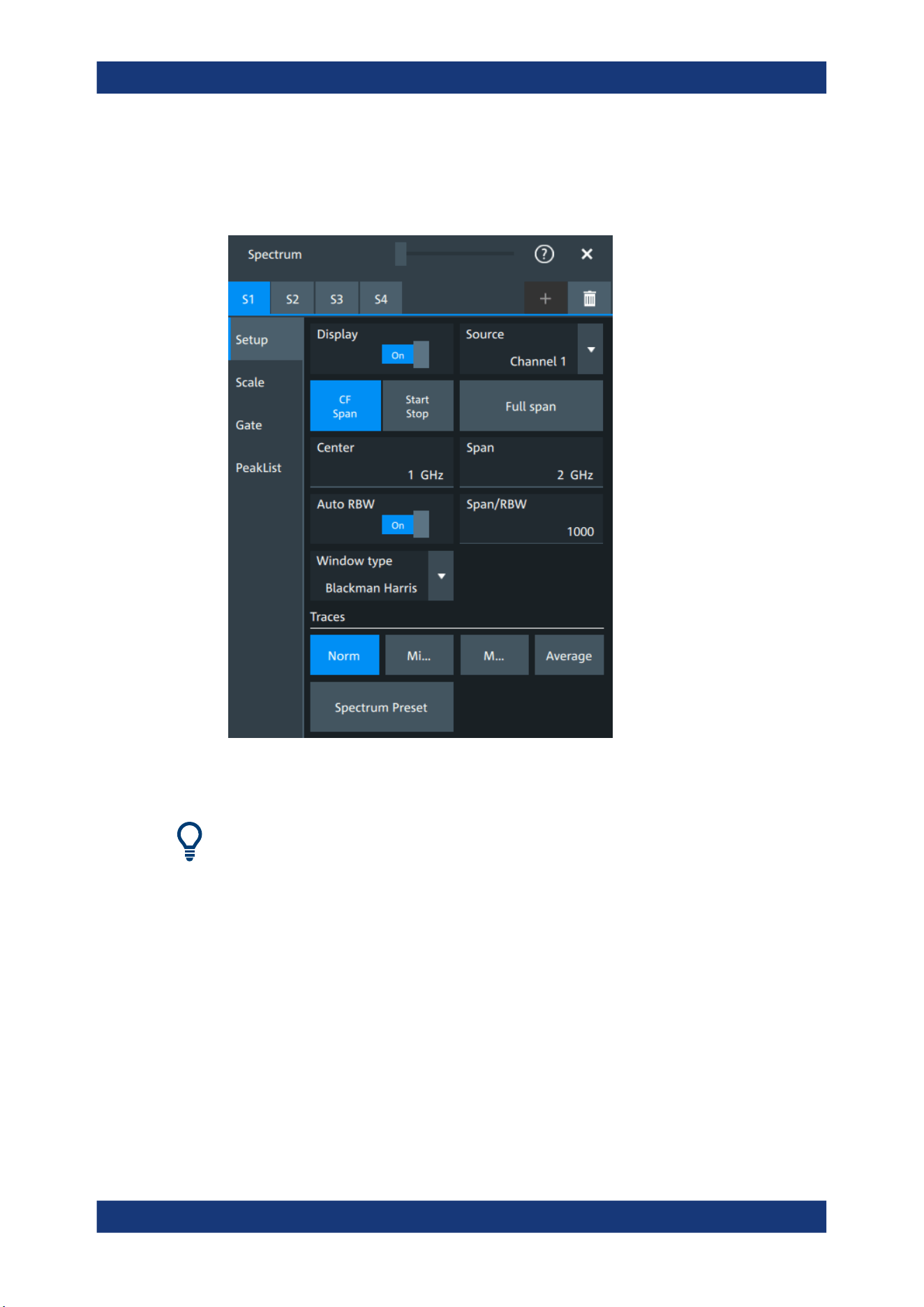
Spectrum analysis
R&S
®
MXO 5 Series
222User Manual 1802.3369.02 ─ 02
10.3 Spectrum setup
Access: "Menu" > "Spectrum" > "Setup" tab.
In this tab, you define the settings for the spectrum window. The display can be restric-
ted to the results for a certain time base extract and to a specified frequency range.
The settings in this dialog are greyed out and cannot be changed, if "Coupling" is
enabled in the "Scale" tab.
Display
Enables the spectrum.
Remote command:
CALCulate:SPECtrum<sp>:STATe on page 594
Source
Selects the source for the spectrum.
Remote command:
CALCulate:SPECtrum<sp>:SOURce on page 593
Full span
Displays the full frequency span.
Spectrum setup

Spectrum analysis
R&S
®
MXO 5 Series
223User Manual 1802.3369.02 ─ 02
CF span, Start Stop
Selects if the frequency span is defined through a "Center"/"Span" pair or through the
"Start"/"Stop".
Center
Defines the position of the displayed frequency range, which is (Center - Span/2) to
(Center + Span/2). The width of the range is defined using the frequency span setting.
Remote command:
CALCulate:SPECtrum<sp>:FREQuency:CENTer on page 590
Span
The span is specified in Hertz and defines the width of the displayed frequency range,
which is (Center - Span/2) to (Center + Span/2). The position of the span is defined
using the "Center" setting.
Remote command:
CALCulate:SPECtrum<sp>:FREQuency:SPAN on page 590
Start
Defines the start frequency of the displayed frequency span.
Remote command:
CALCulate:SPECtrum<sp>:FREQuency:STARt on page 591
Stop
Sets the stop frequency of the displayed frequency span.
Remote command:
CALCulate:SPECtrum<sp>:FREQuency:STOP on page 591
Auto RBW
Couples the frequency span to the "RBW" setting.
If span and RBW values are coupled, changing the span also changes the RBW.
Remote command:
CALCulate:SPECtrum<sp>:FREQuency:BANDwidth[:RESolution]:AUTO
on page 589
Span/RBW
Defines the coupling ratio for Span/RBW.
This setting is only available if "Auto RBW" is enabled.
Remote command:
CALCulate:SPECtrum<sp>:FREQuency:BANDwidth[:RESolution]:RATio
on page 589
RBW
Defines the resolution bandwidth. Note that the resolution bandwidth is correlated with
the span, record length and acquisition time. If a constant record length is to be used,
the RBW can be adapted if the required number of samples cannot be acquired.
Spectrum setup

Spectrum analysis
R&S
®
MXO 5 Series
224User Manual 1802.3369.02 ─ 02
Remote command:
CALCulate:SPECtrum<sp>:FREQuency:BANDwidth[:RESolution][:VALue]
on page 589
Window type
Selects the window type. Windowing helps minimize the discontinuities at the end of
the measured signal interval and thus reduces the effect of spectral leakage, increas-
ing the frequency resolution.
Various different window functions are provided in the R&S MXO 5 to suit different
input signals. Each of the window functions has specific characteristics, including some
advantages and some trade-offs. Consider these characteristics carefully, to find the
optimum solution for the measurement task.
Window type Frequency
resolution
Magnitude
resolution
Measurement recommendation
Rectangular Best Worst Separation of two tones with almost equal amplitudes
and a small frequency distance
Hamming
Hann
Good Poor Frequency response measurements, sine waves, peri-
odic signals and narrow-band noise
Blackman Harris
(default)
Worst Best Mainly for signals with single frequencies to detect har-
monics
Accurate single-tone measurements
Gaussian Good Good Weak signals and short duration
Flattop2 Poor Best Accurate single-tone measurements
Kaiser Bessel Poor Good Separation of two tones with differing amplitudes and a
small frequency distance
Remote command:
CALCulate:SPECtrum<sp>:FREQuency:WINDow:TYPE on page 591
Traces
Spectrum analysis can only be performed on a maximum number of values at once. If
more values must be calculated, the input signal is divided into segments, each of
which is calculated separately. The segments need not to be disjunct. In this case, the
arithmetic mode defines how the final result is calculated from the individual results.
The following methods are available:
"Norm"
The data of only one segment is considered. In effect, no arithmetics
are processed.
"Min hold"
Determines the minimum result for each input value from the data of
the current acquisition and the acquisitions before.
"Max hold"
Determines the maximum result for each input value from the data of
the current acquisition and the acquisitions before.
"Average"
The average is calculated over the number of segments set with
"Average count".
Spectrum setup
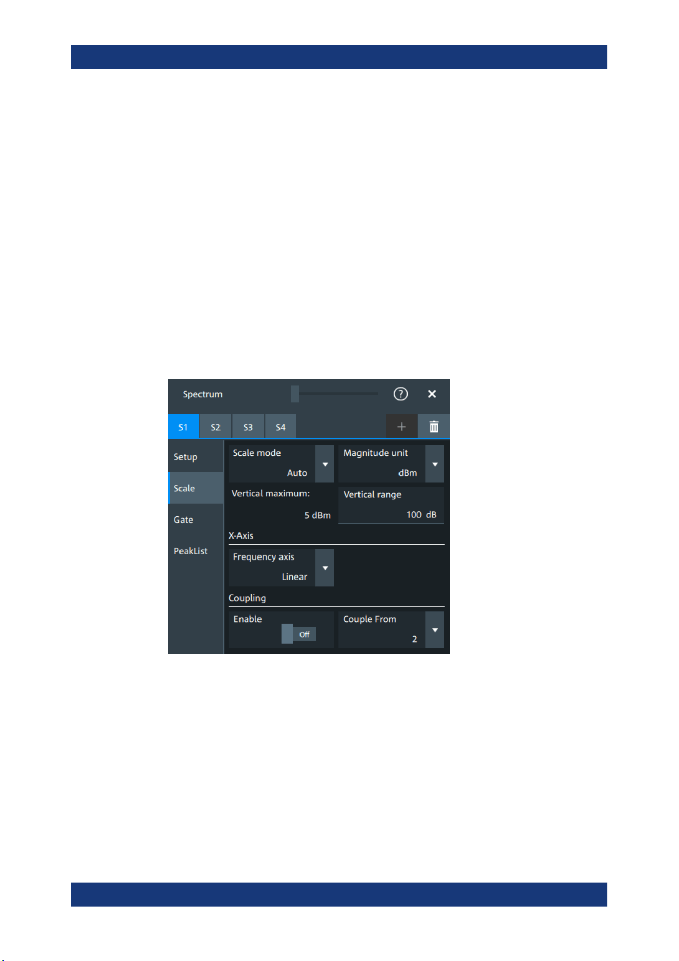
Spectrum analysis
R&S
®
MXO 5 Series
225User Manual 1802.3369.02 ─ 02
Remote command:
CALCulate:SPECtrum<sp>:WAVeform:AVERage:ENABle on page 595
CALCulate:SPECtrum<sp>:WAVeform:AVERage:COUNt on page 595
CALCulate:SPECtrum<sp>:WAVeform:MAXimum:ENABle on page 595
CALCulate:SPECtrum<sp>:WAVeform:MINimum:ENABle on page 595
CALCulate:SPECtrum<sp>:WAVeform:NORMal[:ENABle] on page 596
Spectrum preset
Presets the spectrum measurement.
Remote command:
CALCulate:SPECtrum<sp>:PRESet on page 593
10.4 Spectrum scale
Access: "Menu" > "Spectrum" > "Scale".
Scale mode
By default, the vertical scale is adapted to the current measurement results automati-
cally to provide an optimal display. However, if necessary, you can define scaling val-
ues manually to suit your requirements.
Note: When you change the scaling values manually using the [Scale] rotary knob, the
scale mode is set to "Manual" temporarily.
"Manual"
Enter the required values for "Vertical maximum" and "Vertical range".
"Auto"
"Vertical maximum" is read-only.
Magnitude unit
Sets the unit for the y-axis.
Spectrum scale
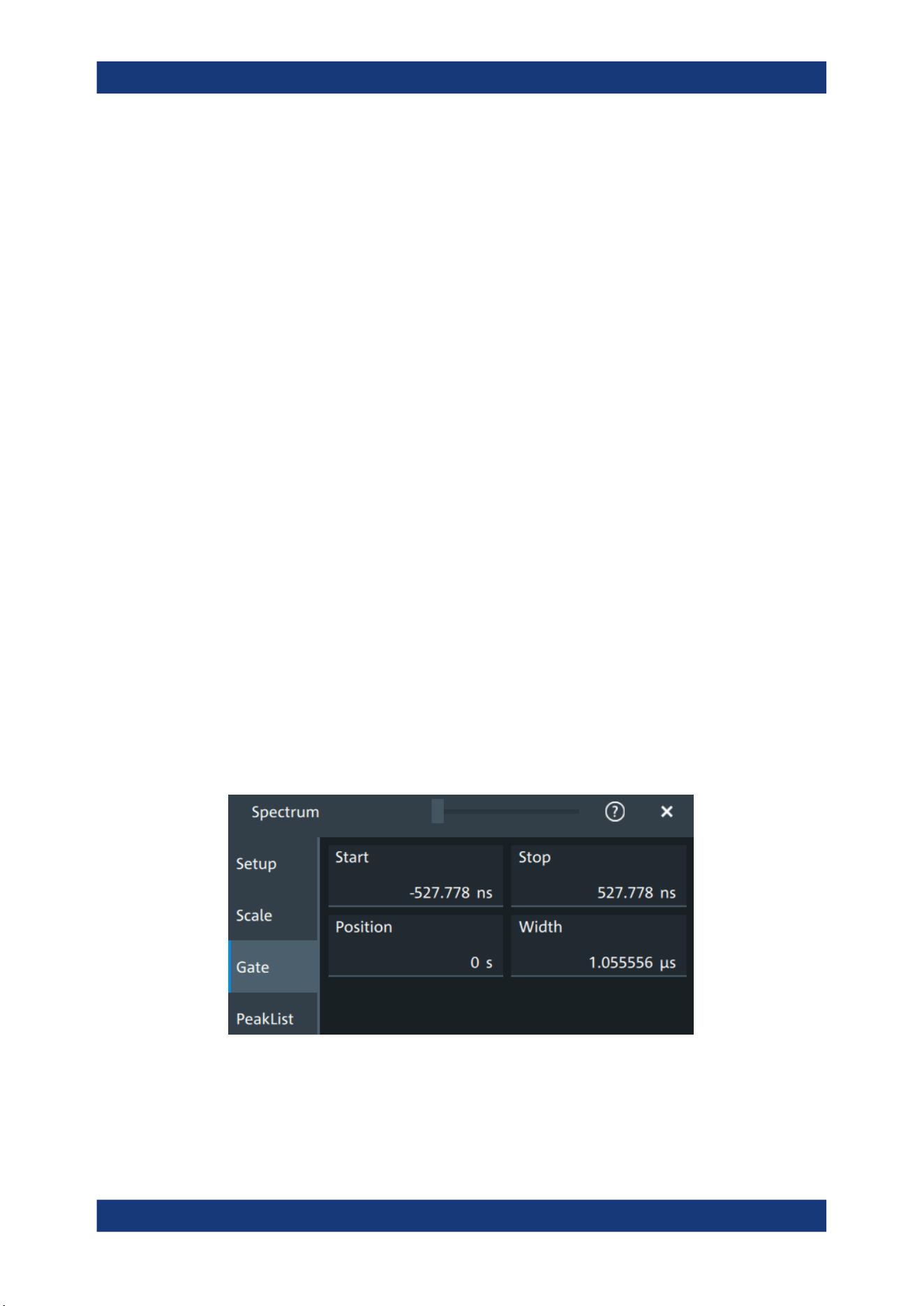
Spectrum analysis
R&S
®
MXO 5 Series
226User Manual 1802.3369.02 ─ 02
The display values are calculated for the termination impedance that is set in "Vertical"
> "Other" tab > "Impedance".
Remote command:
CALCulate:SPECtrum<sp>:MAGNitude:SCALe on page 593
Vertical maximum
Sets the maximum displayed value on the vertical scale.
Remote command:
CALCulate:SPECtrum<sp>:MAGNitude:LEVel on page 592
Vertical range
Sets the range of the spectrum values to be displayed.
Remote command:
CALCulate:SPECtrum<sp>:MAGNitude:RANGe on page 592
Frequency axis
Defines the scaling method for the frequency axis (x-axis) of the spectrogram.
Available are logarithmic and linear scaling.
Remote command:
CALCulate:SPECtrum<sp>:FREQuency:SCALe on page 590
Coupling
If the coupling is enabled, the settings of the current spectrum are coupled to the spec-
trum selected with "Couple from".
10.5 Spectrum gate
Access: "Menu" > "Spectrum" > "Scale"
Spectrum gating restrict the spectrum analysis to a user-defined region of the captured
time domain signal.
Start
Sets the starting value for the gate.
Spectrum gate
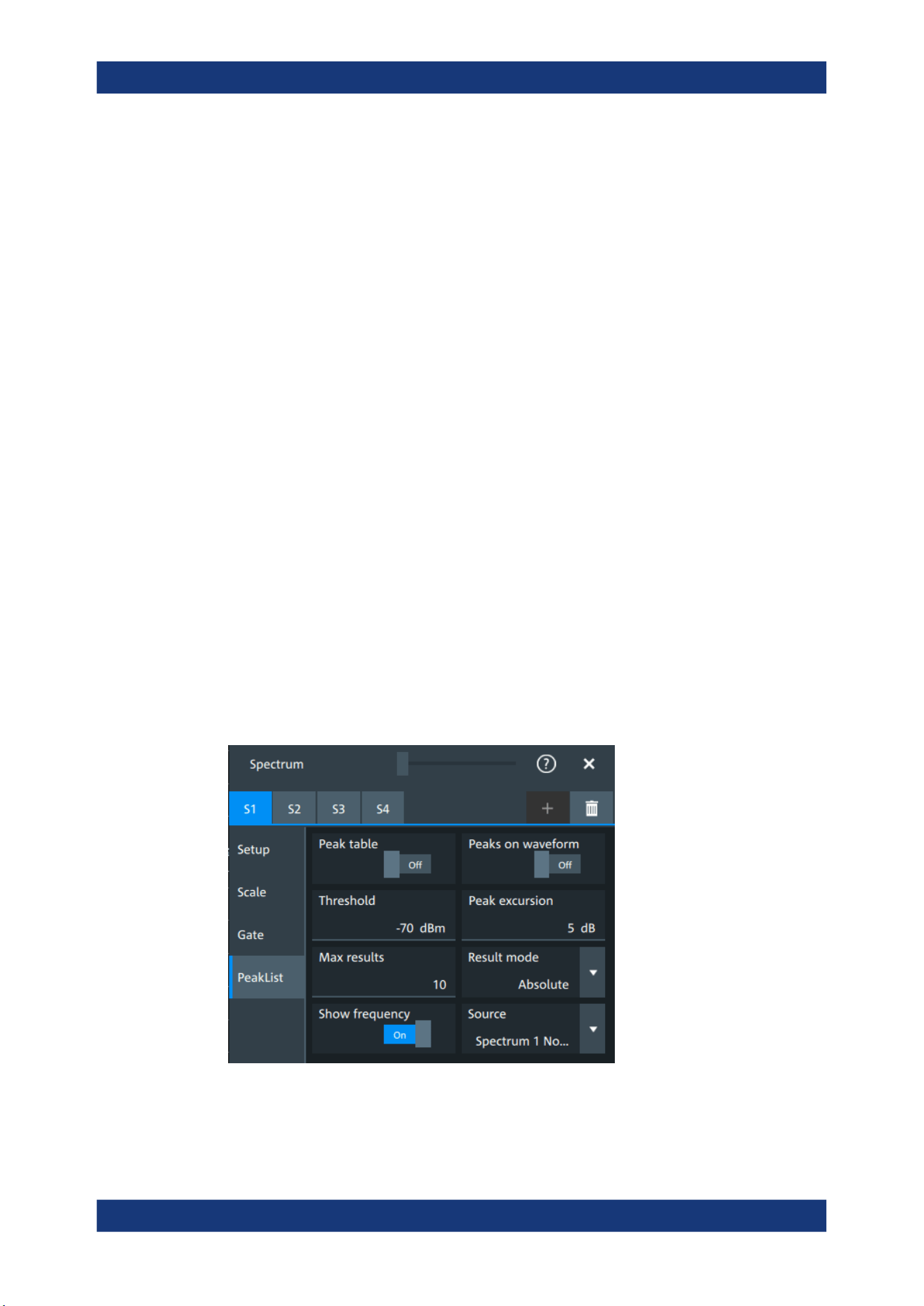
Spectrum analysis
R&S
®
MXO 5 Series
227User Manual 1802.3369.02 ─ 02
Remote command:
CALCulate:SPECtrum<sp>:GATE:STARt on page 596
Stop
Sets the end value for the gate.
Remote command:
CALCulate:SPECtrum<sp>:GATE:STOP on page 597
Position
Sets the position of the displayed frequency range.
The width of the gate is defined using the "Width" setting.
Remote command:
CALCulate:SPECtrum<sp>:GATE:POSition on page 596
Width
Defines the width of the displayed gate.
The position of the span is defined using the "Position" setting.
Remote command:
CALCulate:SPECtrum<sp>:GATE:WIDTh on page 597
10.6 Spectrum peak list
A peak list measurement detects all peaks above a user-definable threshold and
optionally indicates the peaks in the spectrum diagram.
Access: "Menu" > "Spectrum" > "PeakList".
In the peak list dialog, you can define various criteria for a peak search. The peaks can
be indicated in the frequency diagram by peak boxes, and the measured peak frequen-
cies and magnitudes are listed in the peak list table.
Spectrum peak list
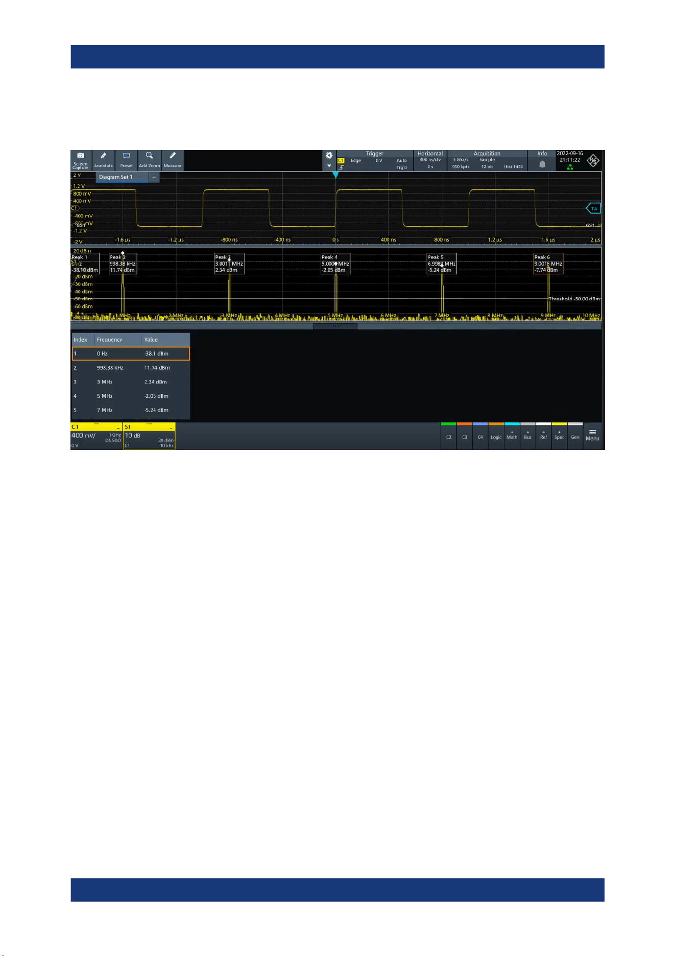
Spectrum analysis
R&S
®
MXO 5 Series
228User Manual 1802.3369.02 ─ 02
The number of determined peaks can be defined. You can sort the results by frequency
or power value, and the peak labels are adjusted accordingly.
Also, you can adjust some of the display settings, see Chapter 5.3.4, "Peak list",
on page 83.
To analyze the peaks in a spectrum, you can also use cursors on the spectrum wave-
form and peak search functions. For details, see Chapter 9.1.3.3, "Peak search tab",
on page 191.
Remote commands query peak results and to change the results display:
●
CALCulate:SPECtrum<sp>:PLISt:RESult[:VALue]? on page 599
●
CALCulate:SPECtrum<sp>:PLISt:SORT:COLumn on page 599
●
CALCulate:SPECtrum<sp>:PLISt:SORT:ORDer on page 600
●
CALCulate:SPECtrum<sp>:PLISt:LABel:INVert on page 601
Peak table
Enables the display of the peak table.
Remote command:
CALCulate:SPECtrum<sp>:PLISt[:STATe] on page 598
Peak on waveform
Displays a box with a description for each detected peak in the spectrum, including the
magnitude. If "Show frequency" is enabled, the frequency values are also displayed.
If this option is disabled, the peaks are marked on the diagram only with a point
marker.
Spectrum peak list
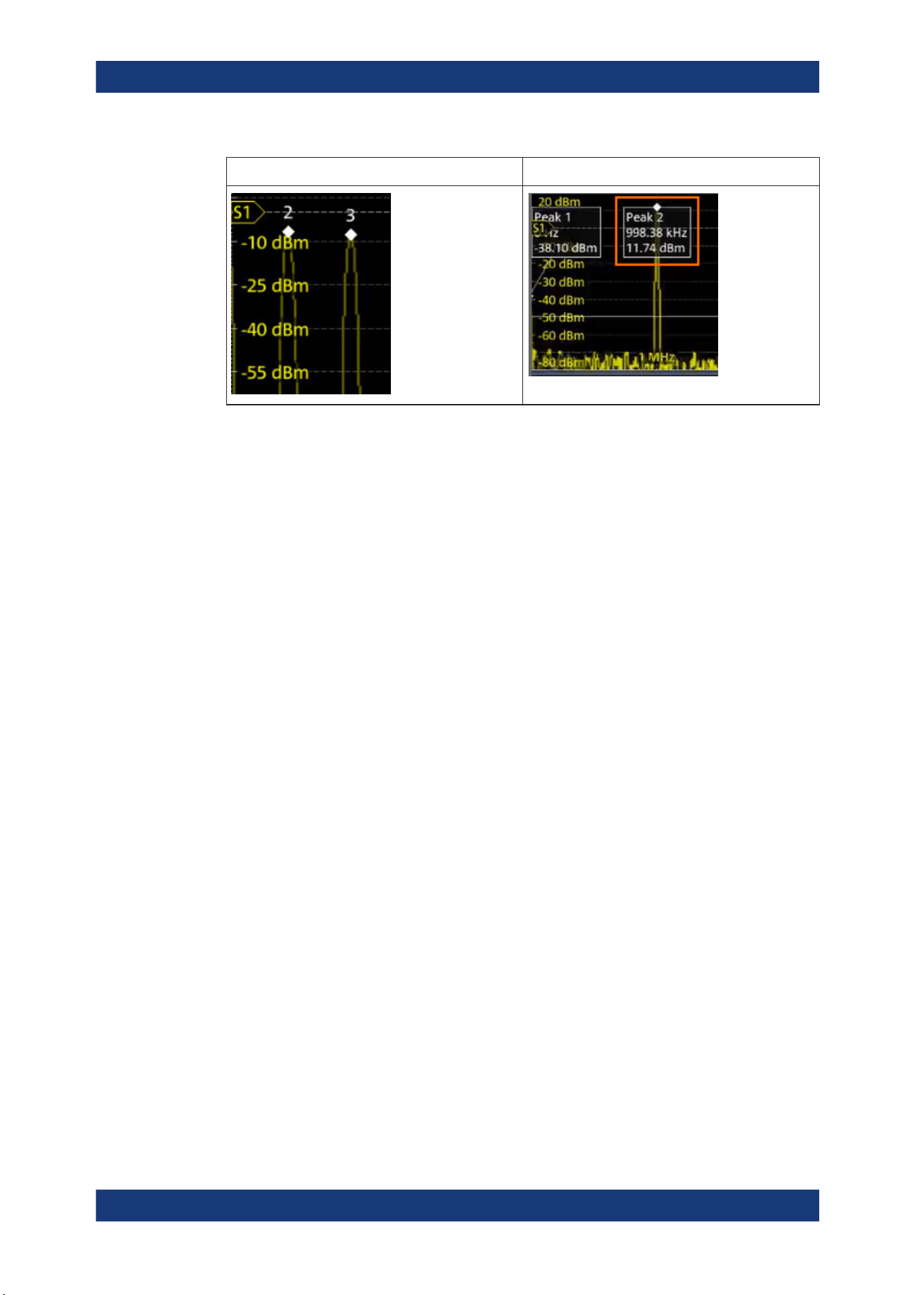
Spectrum analysis
R&S
®
MXO 5 Series
229User Manual 1802.3369.02 ─ 02
"Peak on waveform" > "Off" "Peak on waveform" > "On"
Remote command:
CALCulate:SPECtrum<sp>:PLISt:SPOW on page 599
Threshold
Sets an absolute threshold as an additional condition for the peak search. Only peaks
that exceed the threshold are detected.
This setting is only available for spectrum waveforms. It is valid for cursor measure-
ments, spectrum measurements and peak search.
Remote command:
CALCulate:SPECtrum<sp>:THReshold on page 594
CURSor<cu>:THReshold on page 587
Peak excursion
Defines a relative threshold, the minimum level value by which the waveform must rise
by to be considered as a peak. For the peak to be considered, the excursion threshold
must be met both on the left and the right sides of the peak.
To avoid identifying noise peaks, enter a peak excursion value that is higher than the
noise levels.
This setting is only available for spectrum waveforms. It is valid for cursor measure-
ments, spectrum measurements and peak search.
Example:
In the figure below, 2 peaks are shown, that rise above the defined "Threshold". Peak 1
fulfills the defined "Peak excursion" value and is counted as a peak. Peak 2 does not
fulfill the defined "Peak excursion" value on the right and is not counted as a peak.
Spectrum peak list
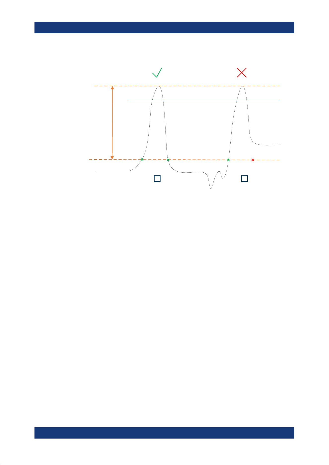
Spectrum analysis
R&S
®
MXO 5 Series
230User Manual 1802.3369.02 ─ 02
Threshold
Peak excursion
1 2
Remote command:
CALCulate:SPECtrum<sp>:PEXCursion on page 594
CURSor<cu>:PEXCursion on page 587
Max results
Sets the maximum number of measurement results that are listed in the result table.
Remote command:
CALCulate:SPECtrum<sp>:PLISt:MAXCount on page 598
Result mode
Selects how the measurement results are displayed.
"Absolute"
The peaks are shown in absolute value, dBm.
"Relative"
The level of the carrier is shown in absolute value dBm. The values of
the peaks are shown relatively to the carrier in dBc.
Remote command:
CALCulate:SPECtrum<sp>:PLISt:MODE on page 598
Show frequency
Includes the frequency of the detected peak in the diagram labels.
Remote command:
CALCulate:SPECtrum<sp>:PLISt:LABel:FREQuency[:STATe] on page 600
Source
Selects the source of the peak table. You can select one of the traces that is enabled
with Traces.
Remote command:
CALCulate:SPECtrum<sp>:PLISt:SOURce on page 599
Spectrum peak list
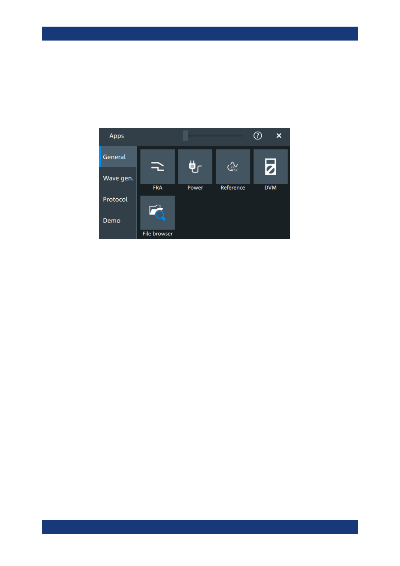
Applications
R&S
®
MXO 5 Series
231User Manual 1802.3369.02 ─ 02
11 Applications
All available applications are provided in the "Apps" dialog.
► To open an application, press the [Apps] key.
Some applications are described in different chapters. See:
●
Chapter 8.4, "Reference waveforms", on page 176
●
Chapter 15, "Waveform generator (option R&S MXO5-B6)", on page 386
●
Chapter 12.5, "File browser dialog", on page 283
●
Chapter 13, "Protocol analysis", on page 285
Also the "Demo" is available in the "Apps" dialog. It is only for demonstration purposes
of the functionalities of R&S MXO 5.
11.1 Frequency response analysis (option R&S MXO5-K36)
The frequency response analysis (FRA) option lets you perform low-frequency
response analysis on your oscilloscope. It characterizes the frequency response of a
variety of electronic devices, including passive filters and amplifier circuits. For
switched-mode power supplies, it measures the control loop response (CLR) and
power supply rejection ratio (PSRR).
The FRA option uses the oscilloscope’s built-in waveform generator to create stimulus
signals ranging from 10 Hz to 100 MHz. Measuring the ratio of the stimulus signal and
the output signal of the DUT at each test frequency, the oscilloscope plots gain and
phase logarithmically.
Having both time and frequency domain views allows you to monitor if the injected sig-
nal causes distortion that leads to errors in the measurement.
Frequency response analysis (option R&S
MXO5-K36)
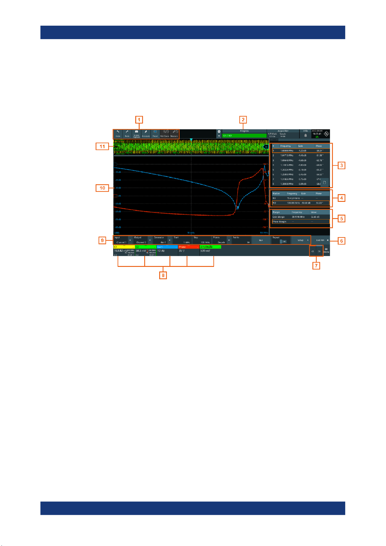
Applications
R&S
®
MXO 5 Series
232User Manual 1802.3369.02 ─ 02
11.1.1 About the frequency response analysis plot
FRA plot display
The FRA plot display is divided into several sections.
Figure 11-1: FRA plot display
1 = Toolbar
2 = Progress bar
3 = FRA result table
4 = Marker value table
5 = Margin value table
6 = Exit app button
7 = Inactive channels
8 = Active channels and plots
9 = FRA plot controls
10 = FRA plot diagram, gain: blue color; phase: red color; amplitude: green color
11 = Channel diagram
Progress bar
Displays the current status of the measurement: how many points have already been
displayed and the total set number of points.
FRA plot diagram
The FRA plot diagram has the frequency presented on the x-axis. The gain (blue color
waveform) and phase (red color waveform) scales are on the y-axis. The gain plot rep-
resents the ratio between input and output. The phase plot shows the phase shift
between input and output.
Frequency response analysis (option R&S
MXO5-K36)

Applications
R&S
®
MXO 5 Series
233User Manual 1802.3369.02 ─ 02
FRA plot result table
In the FRA plot result table, all sample points are displayed with the respective value
for the frequency, gain, phase and amplitude.
Marker value table
There are two markers available for the FRA plot. They are highlighted on the FRA plot
diagram by a white line and the respective marker number 1 or 2. You can move the
markers as needed.
In the marker table you can see the frequency, phase and gain values for both of them.
Remote commands:
●
FRANalysis:MARKer<m>:FREQuency on page 617
●
FRANalysis:MARKer<m>:GAIN? on page 617
●
FRANalysis:MARKer<m>:PHASe? on page 617
Margin value table
The margin value displays the gain and the phase margin frequency and value of the
system. Higher margin values are an indicator for higher stability of the system.
Remote commands:
●
FRANalysis:MARGin:STATe on page 615
●
FRANalysis:MARGin:GAIN:FREQuency? on page 616
●
FRANalysis:MARGin:GAIN:VALue? on page 616
●
FRANalysis:MARGin:PHASe:FREQuency? on page 616
●
FRANalysis:MARGin:PHASe:VALue? on page 616
Vertical position and size of the waveforms
To set the position and the vertical scaling of the gain, phase or amplitude waveforms,
select the waveform and use the vertical [Scale] and [Position] (upper knob) knobs.
The remote commands for setting the position and scales of the are described in
Chapter 17.15.1.4, "Frequency response analysis diagram settings", on page 611.
11.1.2 Using a frequency response analysis
Connecting the test setup
To avoid measurement uncertainties, make sure that the cables connecting the input
and the output of your DUT to the oscilloscope are of similar length.
Starting the FRA
1.
Press the [Apps] key.
Frequency response analysis (option R&S
MXO5-K36)
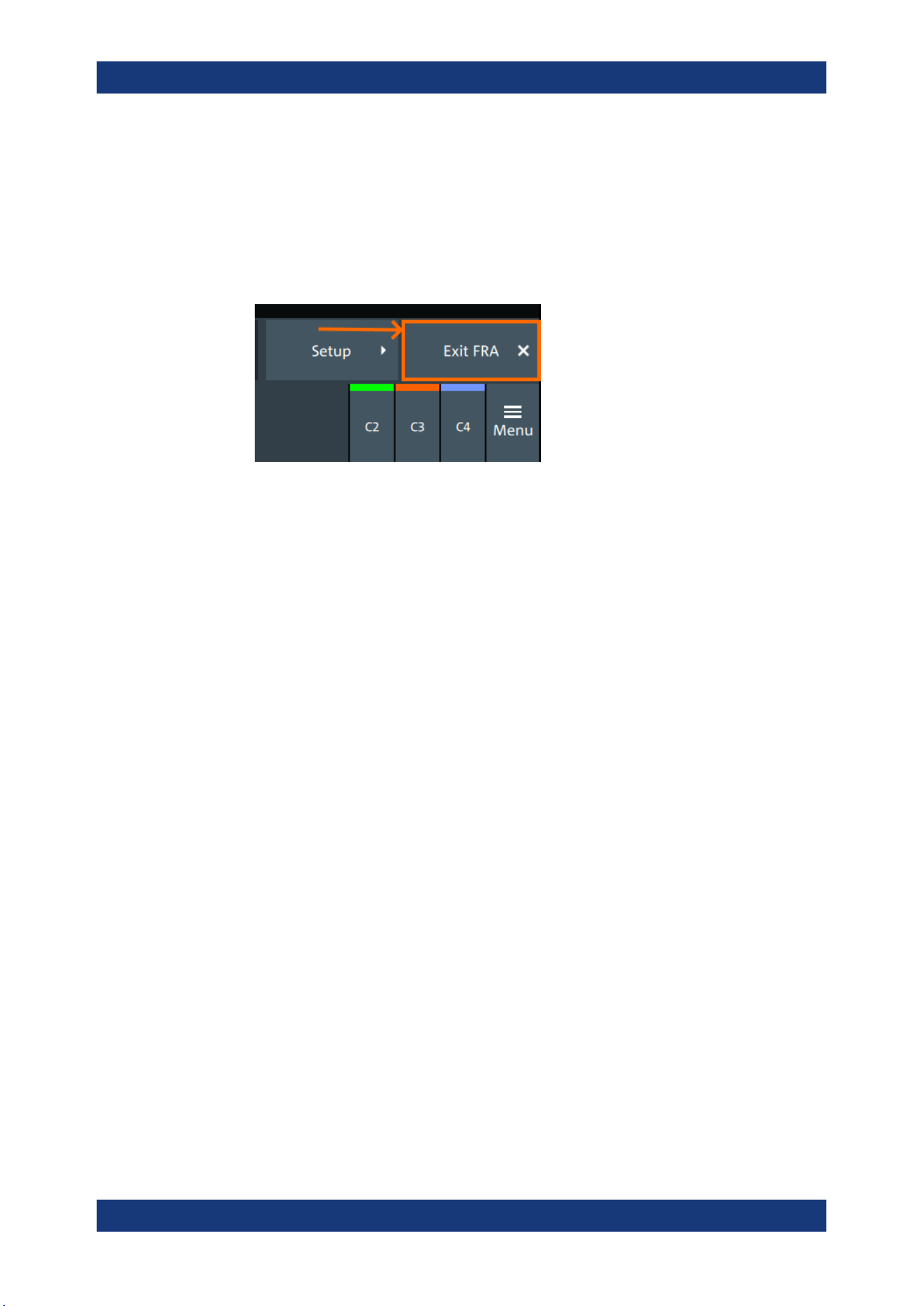
Applications
R&S
®
MXO 5 Series
234User Manual 1802.3369.02 ─ 02
2. In the "General" tab, tap "FRA".
The FRA window opens. Only the settings relevant for the FRA setup are visible in
the "Menu".
Closing the FRA
► Tap the "Exit FRA" key at the bottom-right corner of the display.
11.1.3 Settings for frequency response analysis
The following chapters, describes the settings that you can define for the frequency
response analysis.
11.1.3.1 Setup
Access: [Apps] > "General" > "FRA" > "Setup".
Frequency response analysis (option R&S MXO5-K36)
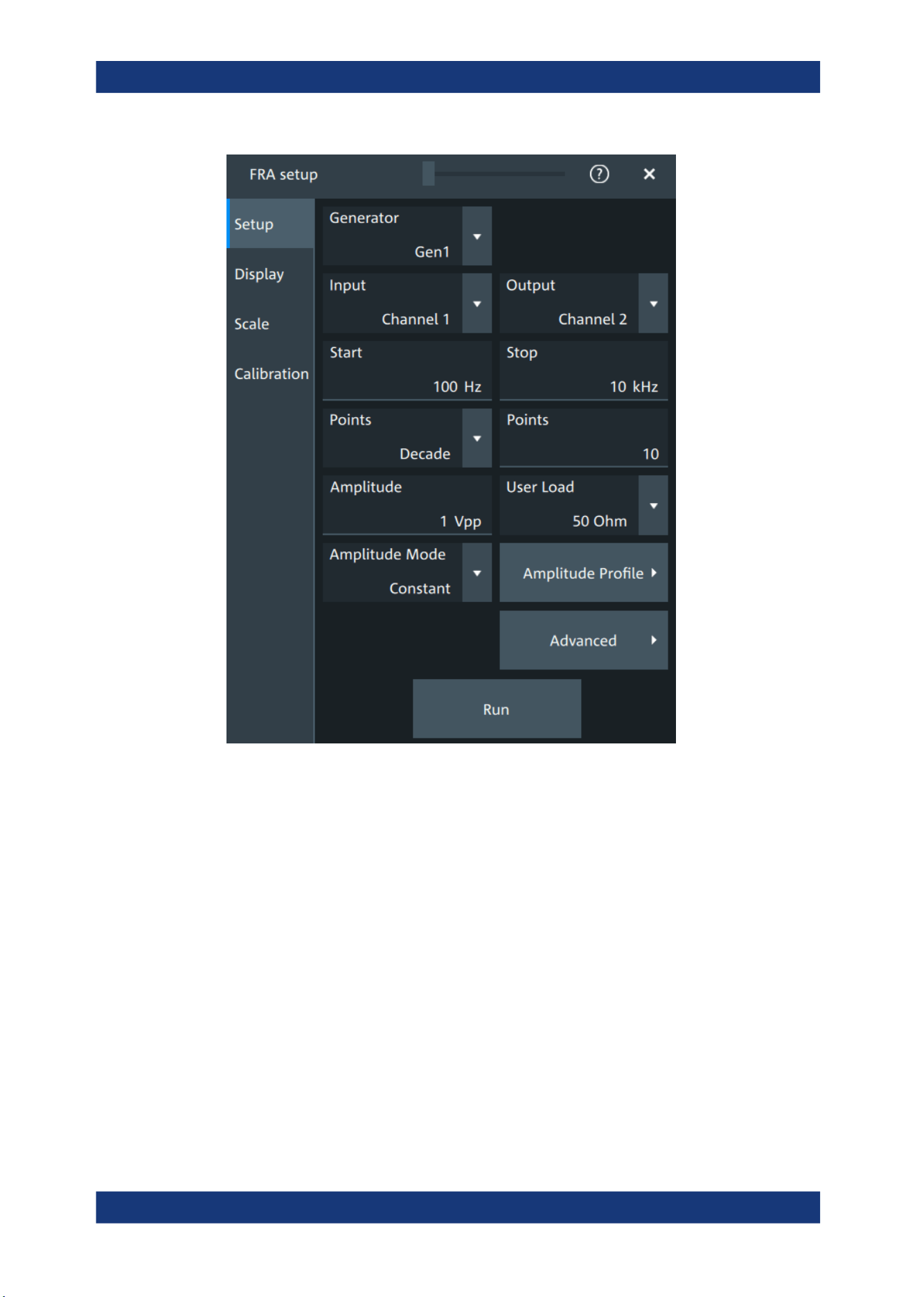
Applications
R&S
®
MXO 5 Series
235User Manual 1802.3369.02 ─ 02
Input
Sets the channel for the input signal of the DUT.
Remote command:
FRANalysis:INPut[:SOURce] on page 606
Output
Sets the channel for the output signal of the DUT.
Remote command:
FRANalysis:OUTPut[:SOURce] on page 607
Generator
Selects the built-in generator to start a frequency sweep for a defined frequency range.
Remote command:
FRANalysis:GENerator[:CHANnel] on page 605
Start, Stop
Set the start and stop frequency of the sweep.
Frequency response analysis (option R&S
MXO5-K36)

Applications
R&S
®
MXO 5 Series
236User Manual 1802.3369.02 ─ 02
Remote command:
FRANalysis:FREQuency:STARt on page 604
FRANalysis:FREQuency:STOP on page 605
Points
Selects, if the number of points are measured as total or per decade and sets the num-
ber of points.
Remote command:
FRANalysis:POINts:TOTal on page 608
FRANalysis:POINts:MODE on page 607
FRANalysis:POINts:LOGarithmic on page 607
Amplitude
Sets a fixed amplitude for the frequency response analysis.
Remote command:
FRANalysis:GENerator:AMPLitude on page 605
User load
Selects the generator voltage display for 50Ω or high impedance load.
Remote command:
FRANalysis:GENerator:LOAD on page 605
Amplitude mode
Selects, if the amplitude is a constant value ("Amplitude") or is defined as an amplitude
profile.
Remote command:
FRANalysis:POINts:MODE on page 607
Amplitude profile
Opens a dialog to set the amplitude profile. See Chapter 11.1.3.2, "Amplitude profile",
on page 237.
You can then define different amplitudes for different frequencies. The amplitude profile
is useful when testing sensitive circuits, where the amplitude gets too high. In this case
distortion might occur.
If this function is enabled, a green colored diagram of the amplitudes for the different
frequencies can be displayed on the screen.
Remote command:
FRANalysis:AMPLitude:MODE on page 604
FRANalysis:AMPLitude:ENABle on page 613
Run
Starts the frequency response analysis.
Remote command:
FRANalysis:STATe on page 603
Repeat
Repeats the measurement, using the same parameters.
Frequency response analysis (option R&S
MXO5-K36)
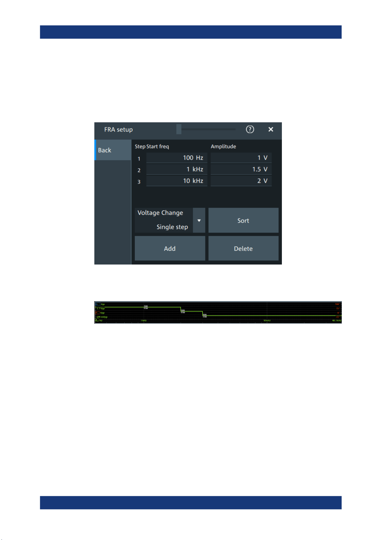
Applications
R&S
®
MXO 5 Series
237User Manual 1802.3369.02 ─ 02
Remote command:
FRANalysis:REPeat on page 608
11.1.3.2 Amplitude profile
Access: [Apps] > "General" > "FRA" > "Setup" > "Amplitude profile".
Opens a dialog to set the amplitude profile. You can then define different amplitudes for
different frequency. The amplitude profile is useful when testing sensitive circuits,
where the amplitude gets too high. In this case distortion can occur.
Step start freq, Amplitude
Set the frequency and amplitude values for the selected point.
Remote command:
FRANalysis:AMPLitude:PROFile:POINt<m>:AMPLitude on page 610
FRANalysis:AMPLitude:PROFile:POINt<m>:FREQuency on page 610
FRANalysis:AMPLitude:PROFile:COUNt on page 609
Voltage change
Selects if the voltage change is done as a single step or as a ramp.
Remote command:
FRANalysis:AMPLitude:PROFile:MODE on page 610
Add
Adds a new point to the amplitude profile.
Remote command:
FRANalysis:AMPLitude:PROFile:APOint on page 609
Frequency response analysis (option R&S
MXO5-K36)
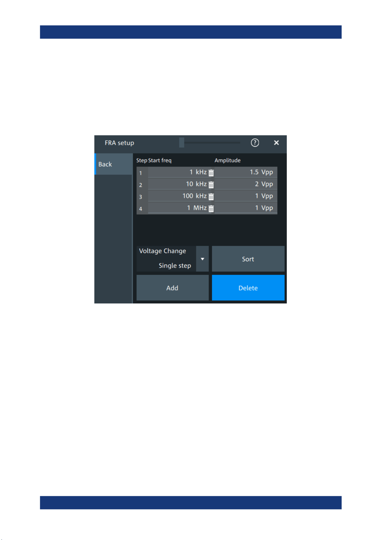
Applications
R&S
®
MXO 5 Series
238User Manual 1802.3369.02 ─ 02
Sort
Sorts the points in the amplitude table by frequency, starting with the lowest frequency.
Remote command:
FRANalysis:AMPLitude:PROFile:SORT on page 609
Delete
If enabled a delete icon appears next to each point in the amplitude profile table. You
can tap on it to delete the amplitude point.
Remote command:
FRANalysis:AMPLitude:PROFile:POINt<m>:REMove on page 609
11.1.3.3 Advanced
Access: [Apps] > "General" > "FRA" > "Setup" > "Advanced".
Frequency response analysis (option R&S MXO5-K36)
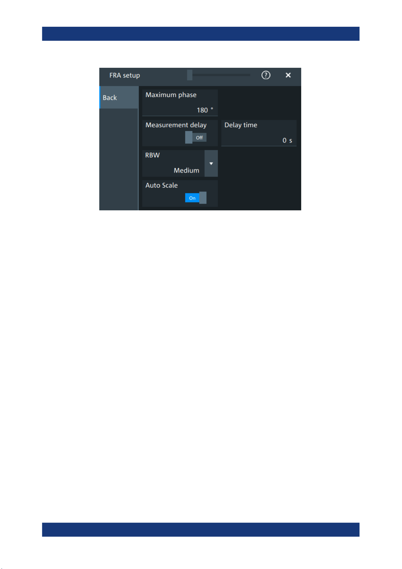
Applications
R&S
®
MXO 5 Series
239User Manual 1802.3369.02 ─ 02
Maximum phase
Sets the upper boundary of the vertical phase window.
The lower boundary is given by "Maximum phase" - 360°.
By default, the "Maximum phase" is set to 180° for a phase window ranging from -180°
to 180° accordingly.
Remote command:
FRANalysis:PHASe:MAXimum on page 608
Measurement delay, Delay time
Sets a time delay, that the system waits before measuring the next point of the plot.
Time delay is helpful in systems that need more time to adapt to the new frequency, for
example if filters with significant time group delays are present.
Remote command:
FRANalysis:MEASurement:DELay:STATe on page 606
FRANalysis:MEASurement:DELay[:TIME] on page 606
RBW
Sets the resolution bandwidth, which determines the number of measurements that are
used for creating the plot.
"High (fast)"
A high RBW value is useful for obtaining a general understanding of a
system's behavior over a wide frequency range. The accuracy of the
measurement is not as good, but the measurement is completed fast.
"Medium"
A medium RBW value is a compromise between the measurement
time and measurement accuracy.
"Low (slow)"
A low RBW value allows for a more detailed analysis of the system.
Since more data needs to be collected, the measurement time would
increase significantly.
Remote command:
FRANalysis:MEASurement:RBW on page 607
Frequency response analysis (option R&S
MXO5-K36)
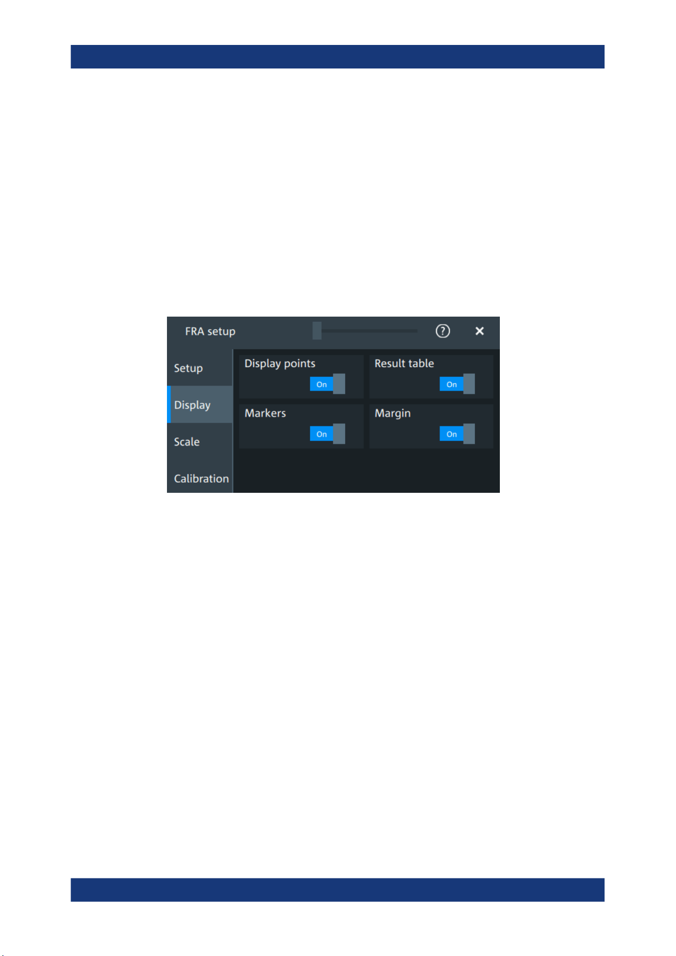
Applications
R&S
®
MXO 5 Series
240User Manual 1802.3369.02 ─ 02
Auto scale
If enabled, the vertical scaling of input and output channel is done automatically for
every new measurement frequency point.
That guarantees a non-disturbed signal and a maximum of measurement resolution.
For Coupling = "DC", the channel offset is also changed to compensate the signal off-
set.
Remote command:
FRANalysis:AUToscale on page 604
11.1.3.4 Display
Access: [Apps] > "General" > "FRA" > "Display".
In this dialog, you can select which elements are displayed in the FRA diagram.
Display points
Enables the display of the measurement points for the frequency response analysis.
Remote command:
FRANalysis:MEASurement:POINt[:DISPlay] on page 606
Result table
Enables the display of the result table for the FRA.
Remote command:
FRANalysis:RESult:STATe on page 615
Markers
Enables the display of the marker table for the FRA.
Remote command:
FRANalysis:MARKer<m>:STATe on page 616
Margin
Enables the display of the margin table for the FRA.
Remote command:
FRANalysis:MARGin:STATe on page 615
Frequency response analysis (option R&S
MXO5-K36)
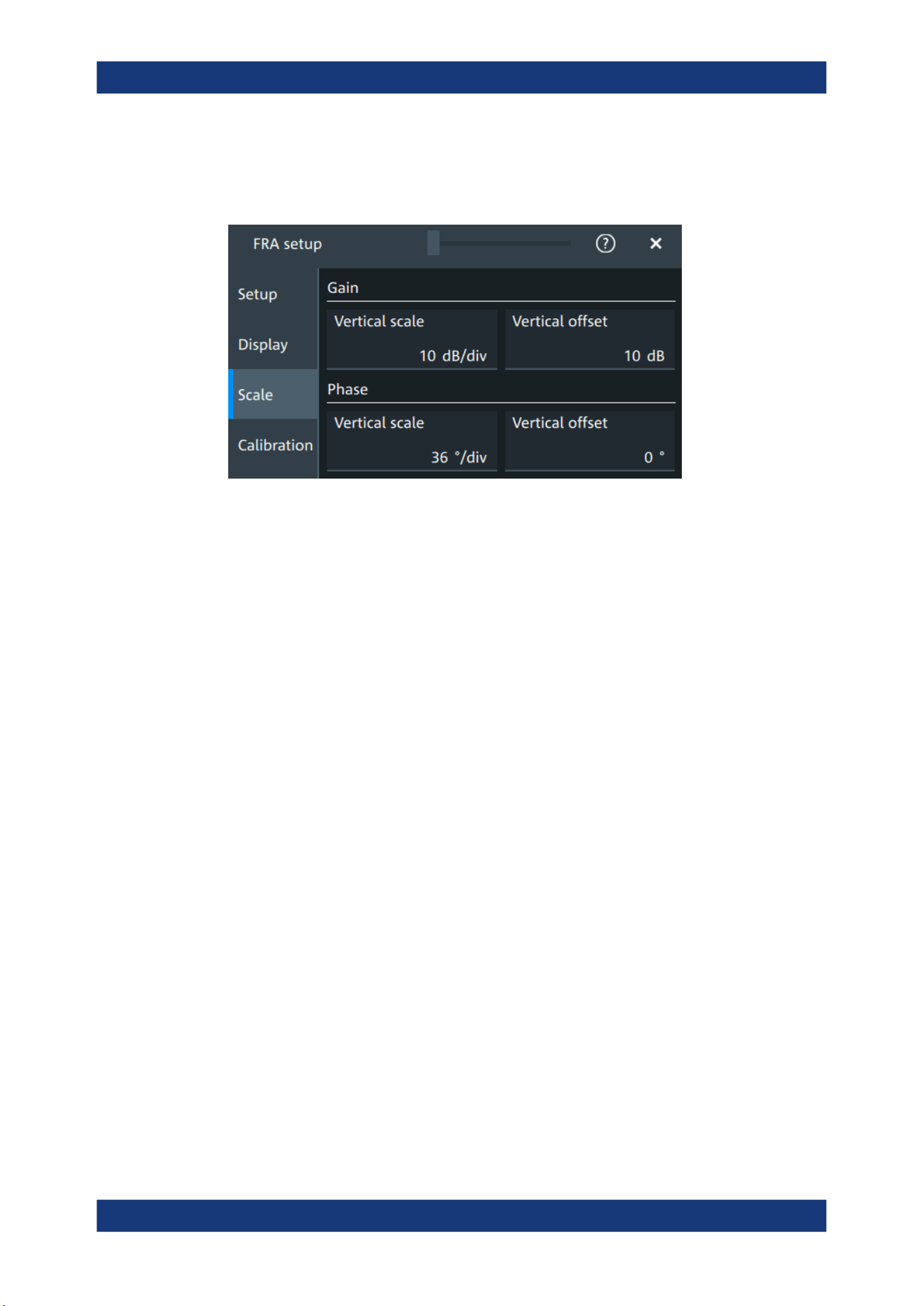
Applications
R&S
®
MXO 5 Series
241User Manual 1802.3369.02 ─ 02
11.1.3.5 Scale
Access: [Apps] > "General" > "FRA" > "Scale".
Figure 11-2: Scale dialog for Mode = Gain/Phase
Vertical scale
Sets the scale of the y-axis in the function diagram.
Vertical offset
Sets a voltage offset to adjust the vertical position on the screen.
11.1.3.6 Calibration
Calibration can be used to compensate the electrical parameter of probes, cables, con-
nector or fixtures.
Access: [Apps] > "General" > "FRA" > "Calibration".
Frequency response analysis (option R&S MXO5-K36)
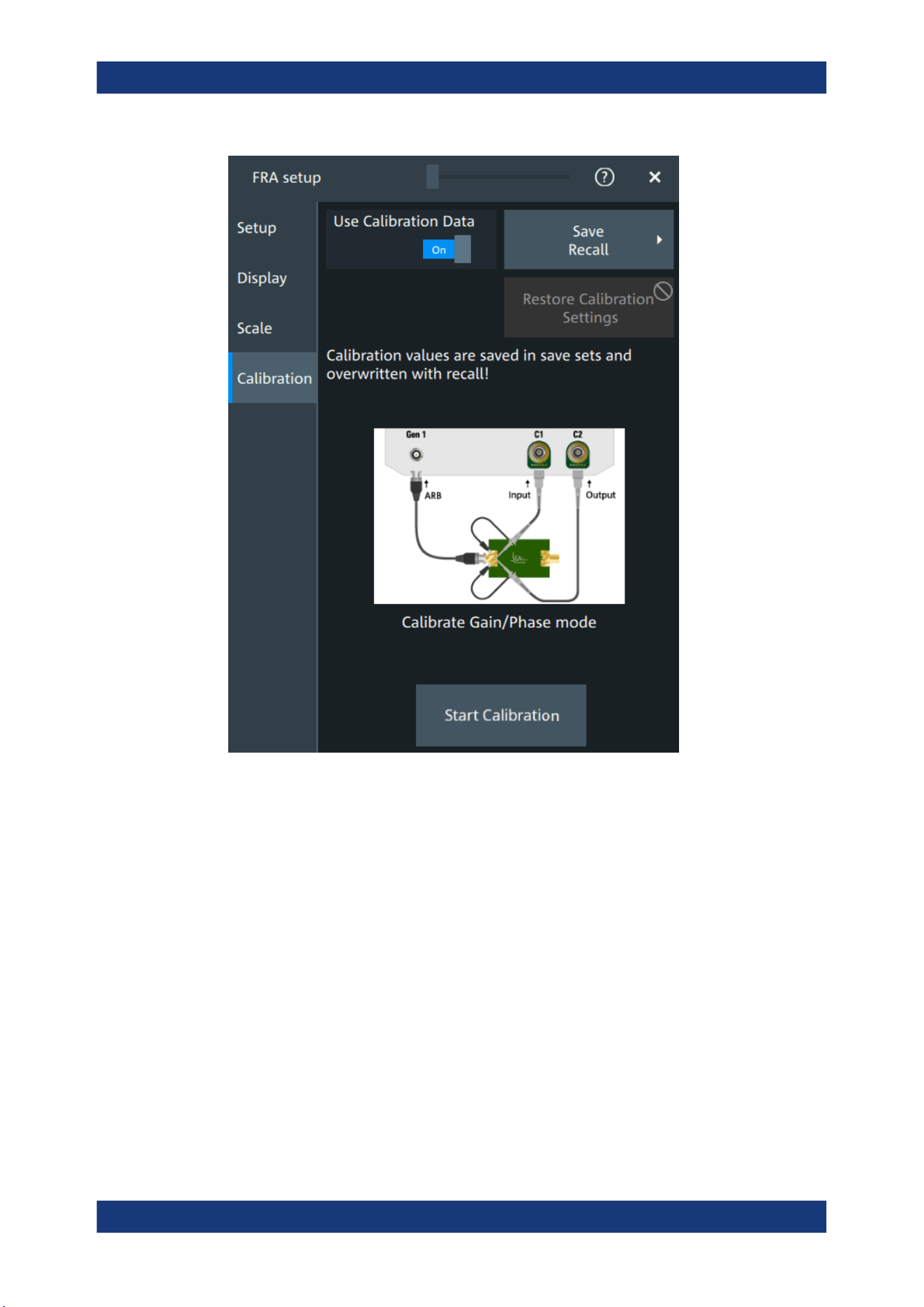
Applications
R&S
®
MXO 5 Series
242User Manual 1802.3369.02 ─ 02
Test setup considerations
Example of a calibration test setup shows an example of a test setup, where the input
probe is connected to [C1] and the output probe is connected to [C2]. The input is also
connected to the ARB generator.
Frequency response analysis (option R&S MXO5-K36)
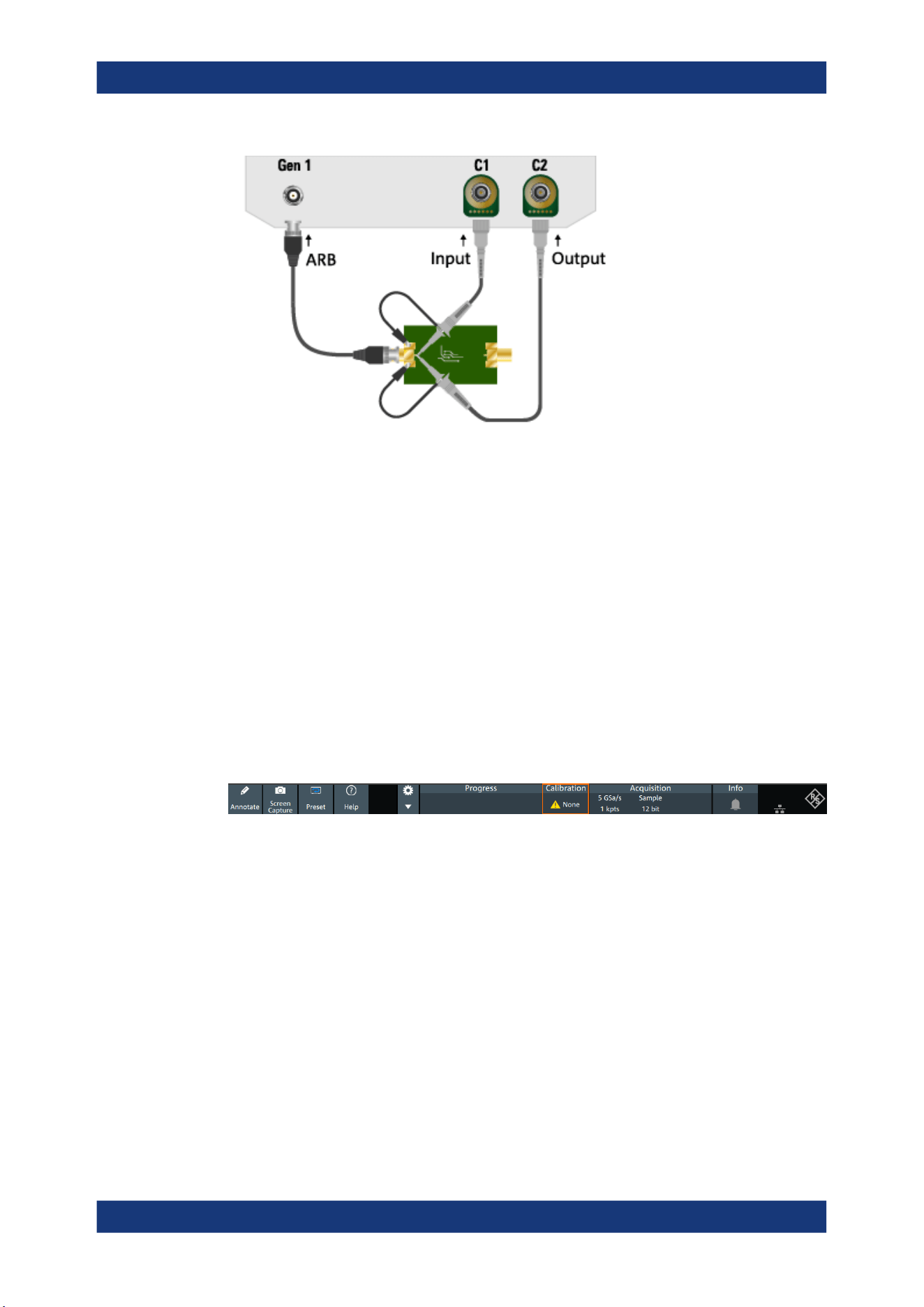
Applications
R&S
®
MXO 5 Series
243User Manual 1802.3369.02 ─ 02
Figure 11-3: Example of a calibration test setup
Input = [C1], [Gen1]
Output = [C2]
Consider also the following:
●
Calibration for FRA is only possible with probes connected to the input and output
channels.
●
For best FRA calibration results, shorten the DUT and place the probe tips as near
as possible to each other.
●
If there a fixture for the DUT it should be part of the calibration setup.
●
If the DUT needs a termination, it is to be conducted with an external termination
direct on DUT output / input.
Calibration state
Once the calibration is started, a label is shown in the toolbar.
The calibration label displays the status of the calibration. The following states are
available:
●
"Valid": calibration values are used
●
"Invalid": device settings changed
●
"Running": a calibration cycle is running
●
"None": not performed or no data
Settings influencing calibration
Calibration is only valid for the settings that are active during its execution. If one of the
following settings is changed, the calibration becomes "Invalid":
●
"Input" and "Output" channel
●
"Channel coupling" and "Bandwidth"
●
"Channel scaling"
Frequency response analysis (option R&S
MXO5-K36)

Applications
R&S
®
MXO 5 Series
244User Manual 1802.3369.02 ─ 02
●
"Generator"
●
"User load"
●
"Amplitude mode"
●
"Amplitude profile"
●
"Amplitude profile" > "Voltage change"
●
"Start" frequency
●
"Stop" frequency
●
"Points" mode and total points
●
"Measurement delay"
●
"Delay time"
●
"RBW"
The following settings are available for the calibration:
Use calibration data
If enabled, the user calibration data is used for the frequency response analysis.
Remote command:
FRANalysis:CALibration:STATe on page 611
Restore calibration settings
Restores the FRA settings, to the values that were selected during the calibration proc-
ess. This allows you to further perform measurements with a valid calibration state.
See also "Settings influencing calibration" on page 243.
Save/Recall
Opens the "Save/Recall" dialog. You can recall a saved saveset.
Start calibration
Starts the calibration. The button is only enabled, if there is a valid test setup.
The state of the calibration process is displayed in the calibration label in the toolbar.
After a calibration is performed successfully, the calibration values are saved automati-
cally.
Remote command:
FRANalysis:CALibration:CALibration on page 611
FRANalysis:CALibration:RESult? on page 611
11.1.4 FRA saving results
Access: [Apps] > "General" > "FRA" > "Setup" > "Save/Recall" >"Results".
Frequency response analysis (option R&S
MXO5-K36)
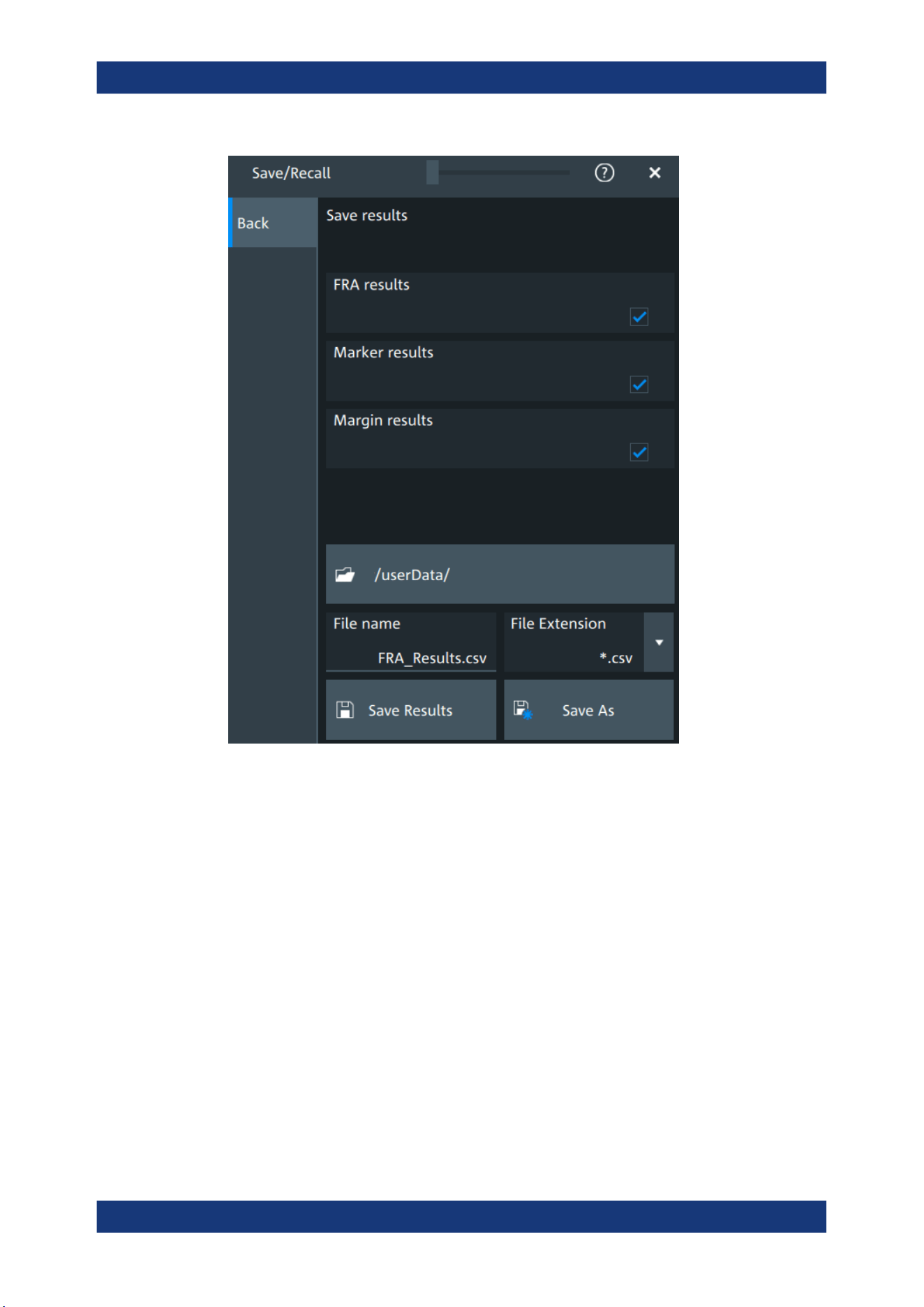
Applications
R&S
®
MXO 5 Series
245User Manual 1802.3369.02 ─ 02
FRA results
In this dialog you can select which result values you want to includes in your FRA
export results file.
The following options are available:
●
"FRA results": includes the frequency, gain, phase and amplitude
●
"Marker results": includes the marker frequency and gain
●
"Margin results": includes the margin gain and phase
Remote command:
EXPort:RESult:SELect:FRA:MARGin on page 618
EXPort:RESult:SELect:FRA:MARKer on page 618
EXPort:RESult:SELect:FRA:RESult on page 618
11.1.5 Dependencies of the measurement setup
When performing the FRA measurement consider the following dependencies on
parameters from the "Vertical" menu.
●
Coupling:
Frequency response analysis (option R&S
MXO5-K36)
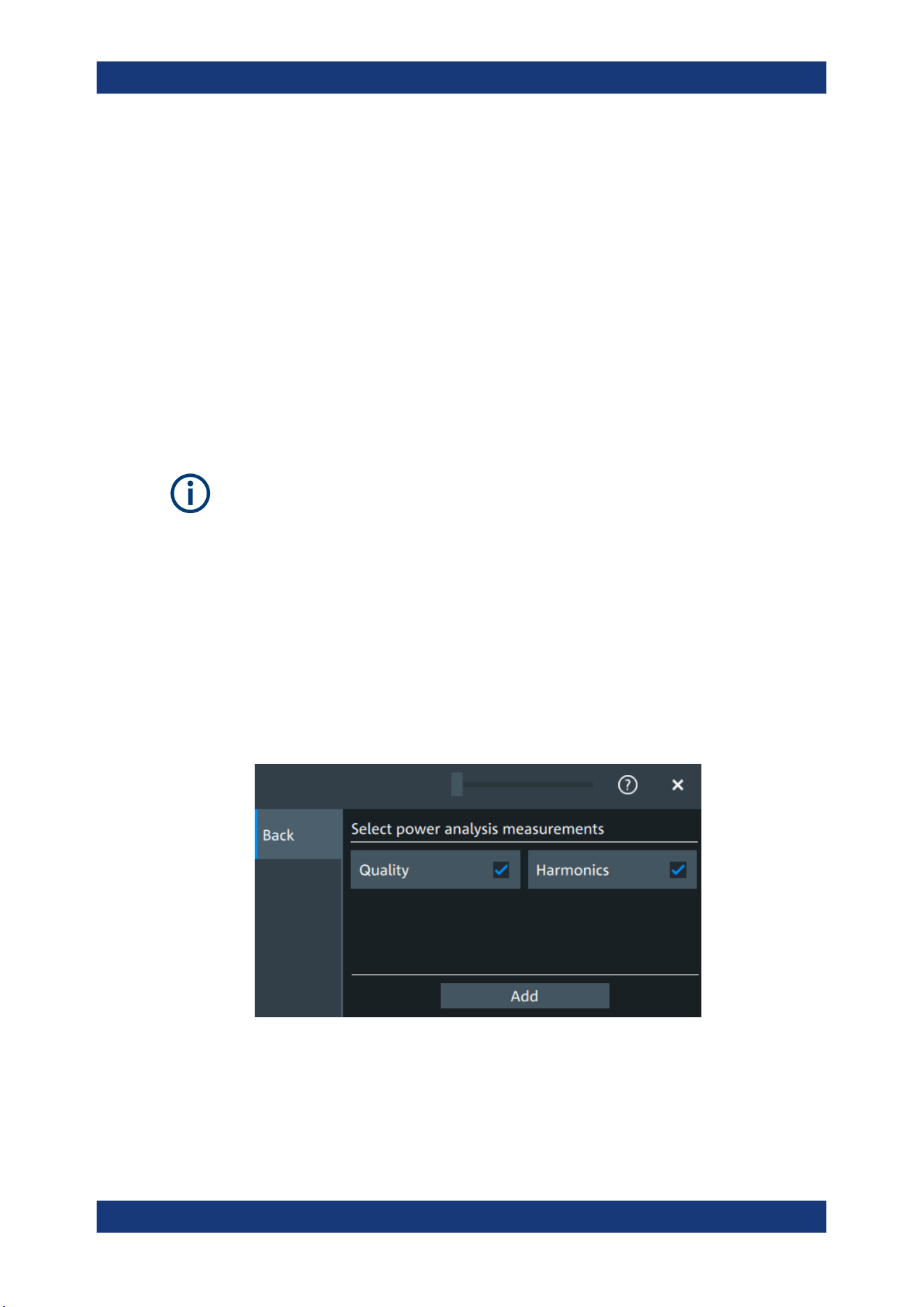
Applications
R&S
®
MXO 5 Series
246User Manual 1802.3369.02 ─ 02
– For frequencies smaller than 10 Hz, the "Coupling" on page 116 is set to DC.
– For frequencies higher than 10Hz, you can select a Coupling manually. The
default set value is AC.
●
The bandwidth value is changed to a higher value, if it the selected bandwidth is
smaller than double the stop frequency.
●
If the bandwidth of the connected probe is lower than the "Stop" frequency, a warn-
ing is shown.
11.2 Power analysis (option R&S MXO5-K31)
With the R&S MXO 5 and option R&S MXO5-K31, you can perform power analysis
measurements.
For best measurement results, it is recommended to set Bandwidth = 20 MHz.
If using the HD mode, it is recommended to set Bandwidth = 100 MHz.
11.2.1 Power measurement selection
To add a new power measurement
1. Tap the "Menu" > "Apps" > "General" tab > "Power", to open the power measure-
ment dialog.
2. In the "Analysis" tab, tap "Add".
A dialog opens to select the power measurements.
3. Tap on a power measurement from the list to enable it.
Selected measurements are marked with a blue check mark in their checkbox.
4. Tap "Add" to add the selected measurements.
All selected measurements are enabled.
Power analysis (option R&S
MXO5-K31)
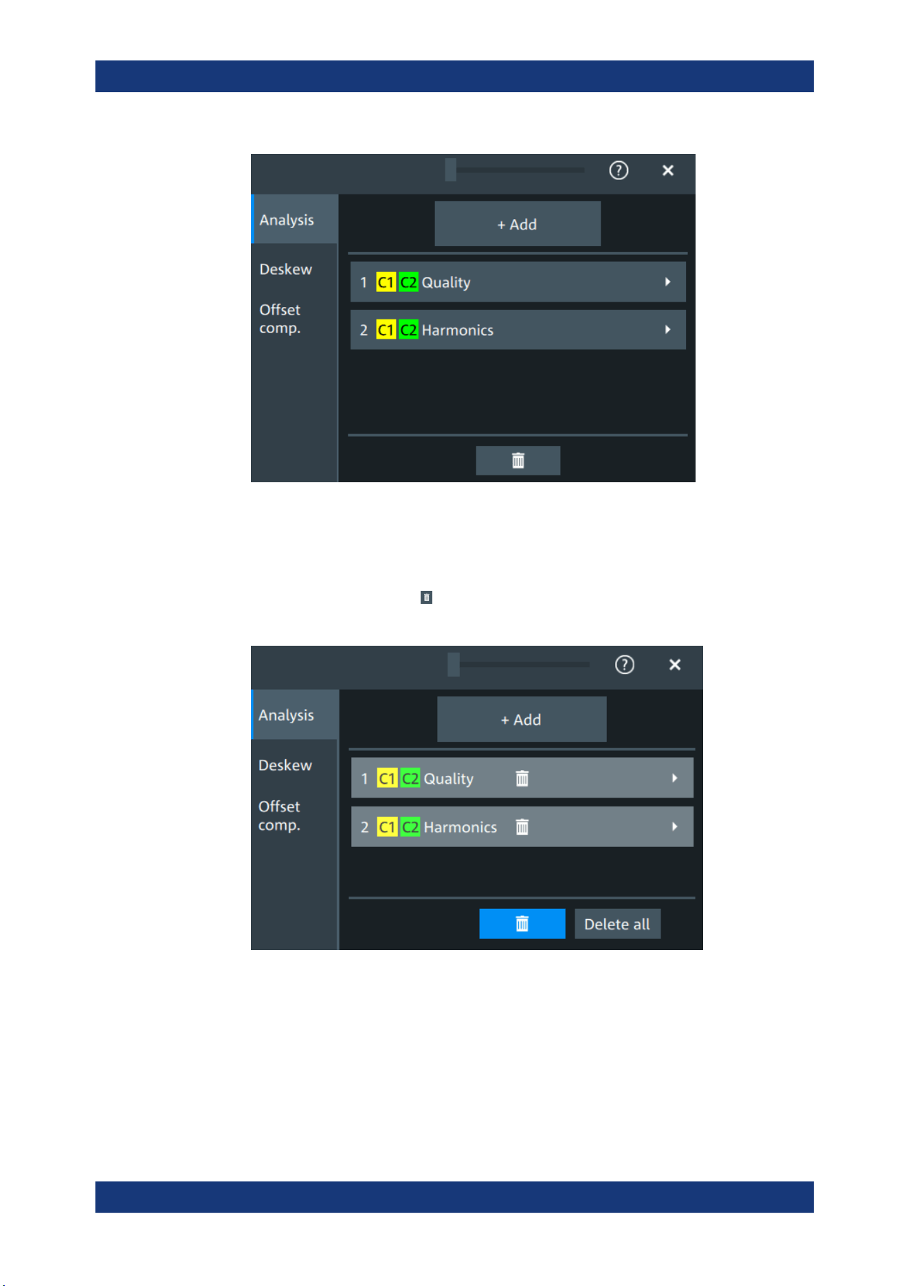
Applications
R&S
®
MXO 5 Series
247User Manual 1802.3369.02 ─ 02
To delete a measurement
1. Tap the "Menu" > "Apps" > "General" tab > "Power", to open the power measure-
ment dialog.
2.
In the "Analysis" tab, tap .
A delete icon appears in the selection button of each measurement.
3. Tap on the button of the power measurement that you want to delete. Alternatively,
tap "Delete All" to delete all measurements.
Power analysis (option R&S
MXO5-K31)
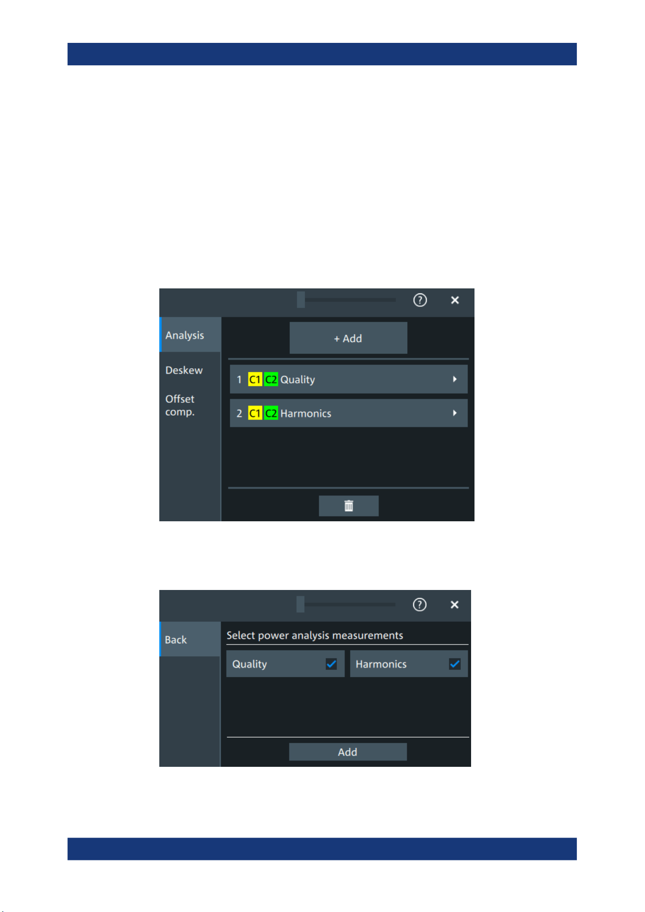
Applications
R&S
®
MXO 5 Series
248User Manual 1802.3369.02 ─ 02
11.2.2 Power measurements
11.2.2.1 Power analysis settings
In the "Analysis" you can enable the power analysis and access the dialog to select the
power analysis measurements.
You can add up to 6 power analysis measurements. You can also add several instan-
ces of the same measurement.
Also you can access the settings dialogs for all enabled power analysis measure-
ments.
Add
Opens a dialog to select the power analysis measurements.
Available are power quality and power harmonics measurements.
Power analysis (option R&S MXO5-K31)

Applications
R&S
®
MXO 5 Series
249User Manual 1802.3369.02 ─ 02
Remote command:
POWer<m>[:ENABle] on page 619
POWer<m>:TYPE on page 619
11.2.2.2 Power quality
In an electric circuit power is a measure for the rate of flow of energy at a certain point
of the circuit. The active power of a circuit, or the energy that can be used for work, is
the portion of energy that is transferred in one direction over a complete cycle of the
AC waveform. In AC circuits, however, inductive and capacitive elements can store
energy temporarily. This portion of the power flow known as reactive power is then
returned to the source without doing any work.
The power quality analysis measurements include the active power, the reactive
power, the apparent power and the power factor. The crest factors and the phase angle
between the current and voltage are also measured. These properties describe the
power transfer in the system and allow you to characterize the power quality of the sys-
tem.
Required probes:
●
Differential voltage probe
●
Current probe
Configuring power quality
For details of the configuration settings, see "Power quality settings" on page 251.
1. Add a new power quality measurement as described in "To add a new power mea-
surement" on page 246.
2. In the "Analysis" tab, tap the "Quality" measurement.
The "Quality" setup dialog opens.
Power analysis (option R&S MXO5-K31)
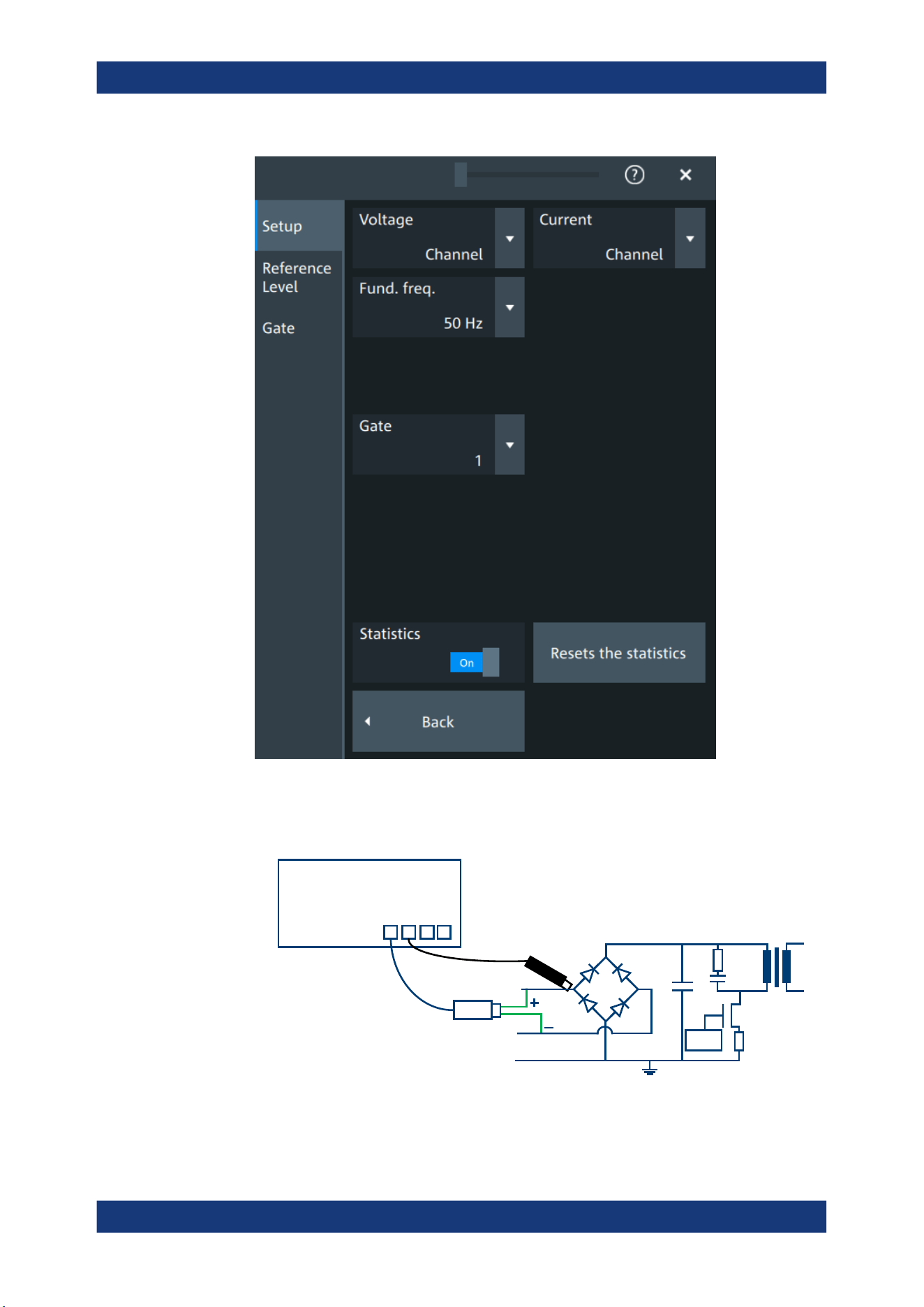
Applications
R&S
®
MXO 5 Series
250User Manual 1802.3369.02 ─ 02
3. Connect the differential voltage probe and the current probe to the oscilloscope.
4. Connect the probes to the DUT:
PWM
L
N
E
Drain
Source
Gate
MXO
C1
C2 C3 C4
Current probe
Voltage probe
Power analysis (option R&S MXO5-K31)
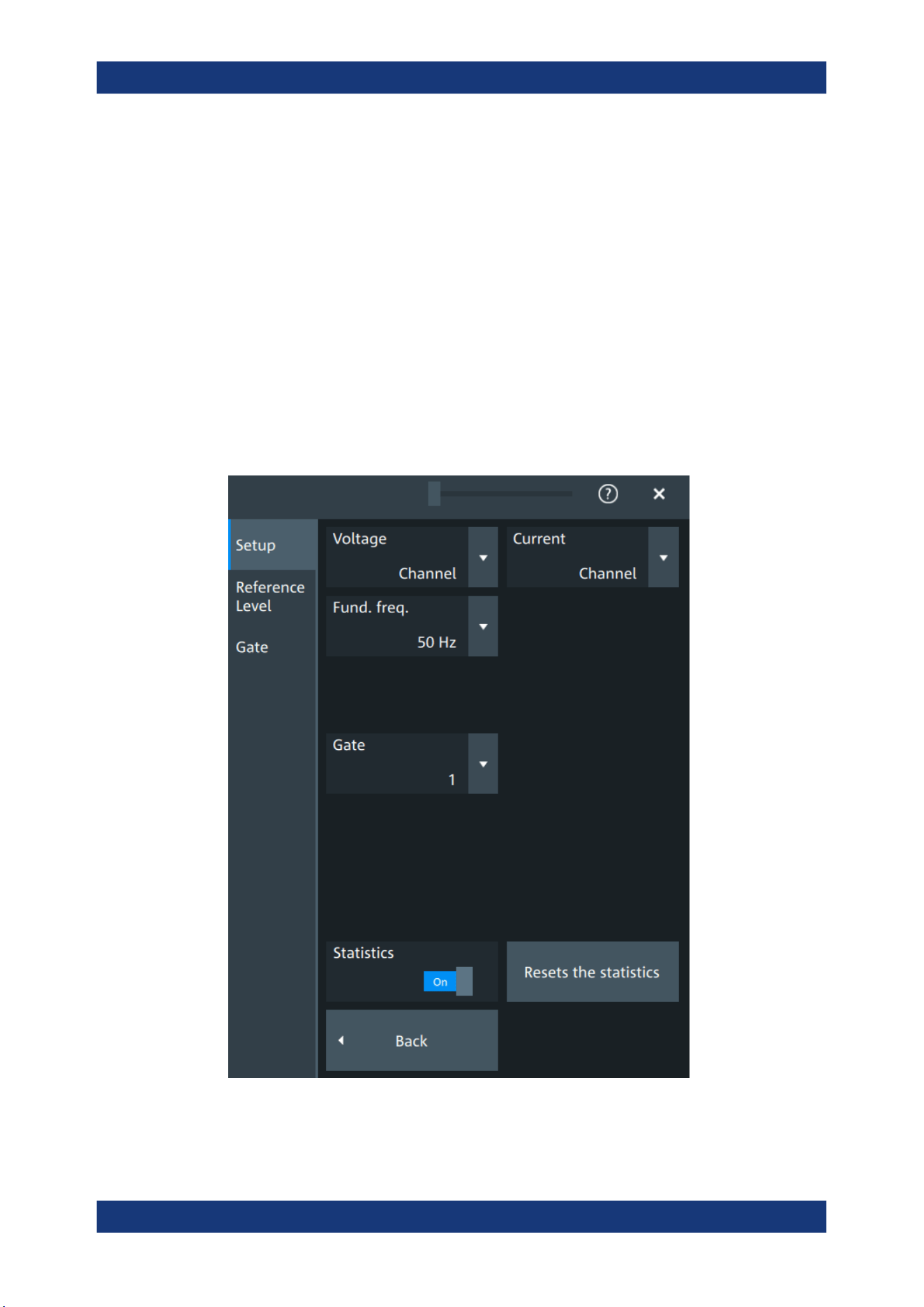
Applications
R&S
®
MXO 5 Series
251User Manual 1802.3369.02 ─ 02
a) Connect the positive (+) signal socket of the differential voltage probe to the
line of the AC input.
b) Connect the negative (-) signal socket of the differential voltage probe to the
neutral of the AC input.
c) Connect the current probe to the line of the AC input.
5. Select the correct channels for the "Voltage" and the "Current" probes.
6. Set the "Fund. Freq" according to your signal.
7. If necessary, enable "Statistics".
On the screen, you can see the measurement waveforms of the current, the volt-
age and the power. Also, the result box with numeric measurement results is
shown. For details, see "Power quality results" on page 253.
Power quality settings
Voltage
Selects the channel for the voltage source.
Power analysis (option R&S
MXO5-K31)

Applications
R&S
®
MXO 5 Series
252User Manual 1802.3369.02 ─ 02
Remote command:
POWer<m>:QUALity:SOURce[:VOLTage] on page 621
Current
Selects the channel for the current source.
Remote command:
POWer<m>:QUALity:SOURce:CURRent on page 620
Fund. Freq
Selects the input frequency of the source signal.
Remote command:
POWer<m>:QUALity:FREQuency[:VALue] on page 621
POWer<m>:QUALity:FREQuency:USER on page 621
Statistics
Activates or deactivates the statistical evaluation for the power measurement. If statis-
tics are enabled, the following results are calculated:
Label Description
Current Current value
Max Maximum value
Min Minimum value
Mean Average
RMS Root mean square
σ (S-dev) Standard deviation
Event count Number of measured events
Wave count Number of waveforms (acquisitions) the measurement is based on
Resets the statistics
Resets the statistical results for the respective power measurements, and starts a new
statistical evaluation if the acquisition is running.
Power analysis (option R&S MXO5-K31)
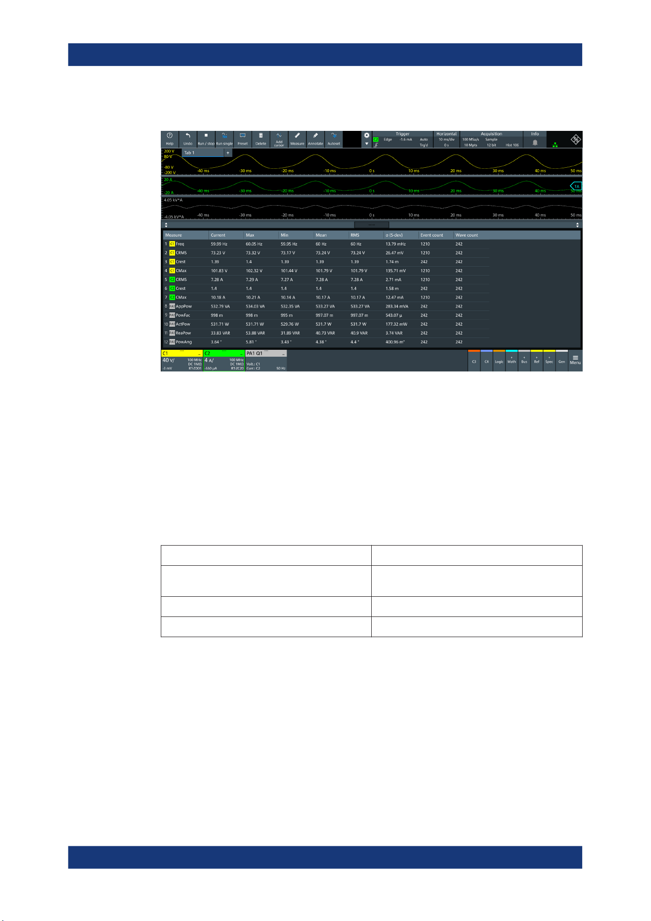
Applications
R&S
®
MXO 5 Series
253User Manual 1802.3369.02 ─ 02
Power quality results
The results of power quality measurements are provided in two ways:
●
The diagram shows the graphical presentation of:
– The voltage waveform
– The current waveform
– The power waveform that is the product of the current and voltage waveforms
●
The result box displays the numeric measurement results:
Voltage and current results
The voltage and current results are defined as follows:
Result Description
Current / Voltage RMS Square root of the mean of the square of the current
or voltage averaged over N cycles
Voltage Frequency Frequency of the signal
Current / Voltage Crest factor Peak value / RMS value
Power results
The power in a system is described by several physical quantities:
Power analysis (option R&S
MXO5-K31)

Applications
R&S
®
MXO 5 Series
254User Manual 1802.3369.02 ─ 02
Result Unit Formula Description
Apparent power, |S| VA |S| = V
RMS
∙
I
RMS
(averaged over N cycles)
|S| is the magnitude of the
vector sum of active and
reactive power (the complex
power S).
Reactive power, Q VAR
(Volt‑Ampere
reactive)
Q = |S| sin
φ
Power flow that is temporally
stored in a system because of
the inductive and capacitive
elements.
Power factor, P
Factor
- P
Factor
= |P| / |S| Measure of the system effi-
ciency. The value varies
between -1 and 1.
Active power, P W P = V
INSTANTENEOUS
∙
I
INSTANTENEOUS
(averaged over N cycles)
Energy of the system that can
be used to do work.
Phase, φ °
φ
= acos (P
Factor
) Phase angle between the cur-
rent and the voltage sine
waves.
Reference level
For a description of the gate settings, see Chapter 11.2.3, "Reference level",
on page 259.
Gate
For a description of the gate settings, see Chapter 9.2.2, "Gate settings for measure-
ments", on page 197.
11.2.2.3 Power harmonic
Current harmonics appear in an electric power system due to nonlinear electric loads.
The harmonics can be ejected back into the AC line and disturb other equipment on
the grid. To avoid this disturbance, there are often standards of compliance that con-
sumer or industry end-products must meet.
The "Harmonics" analysis tests the devices according to the precompliance standards
EN 61000-3-2, MIL-STD-1399 and RTCA DO-160.
Required probes:
●
Differential voltage probe
●
Current probe
Configuring power harmonics
For details of the configuration settings, see "Power harmonic settings" on page 256.
1. Add a new power quality measurement as described in "To add a new power mea-
surement" on page 246.
2. In the "Analysis" tab, tap the "Harmonics" measurement.
Power analysis (option R&S
MXO5-K31)
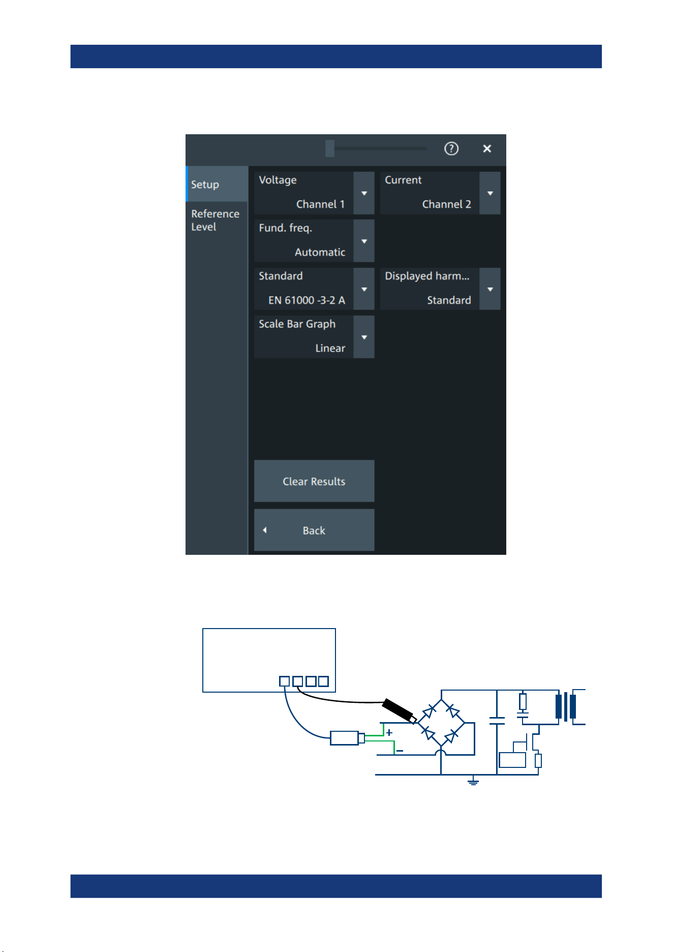
Applications
R&S
®
MXO 5 Series
255User Manual 1802.3369.02 ─ 02
The "Harmonics" setup dialog opens.
3. Connect the differential voltage probe and the current probe to the oscilloscope.
4. Connect the probes to the DUT:
PWM
L
N
E
Drain
Source
Gate
MXO
C1
C2 C3 C4
Current probe
Voltage probe
Power analysis (option R&S MXO5-K31)
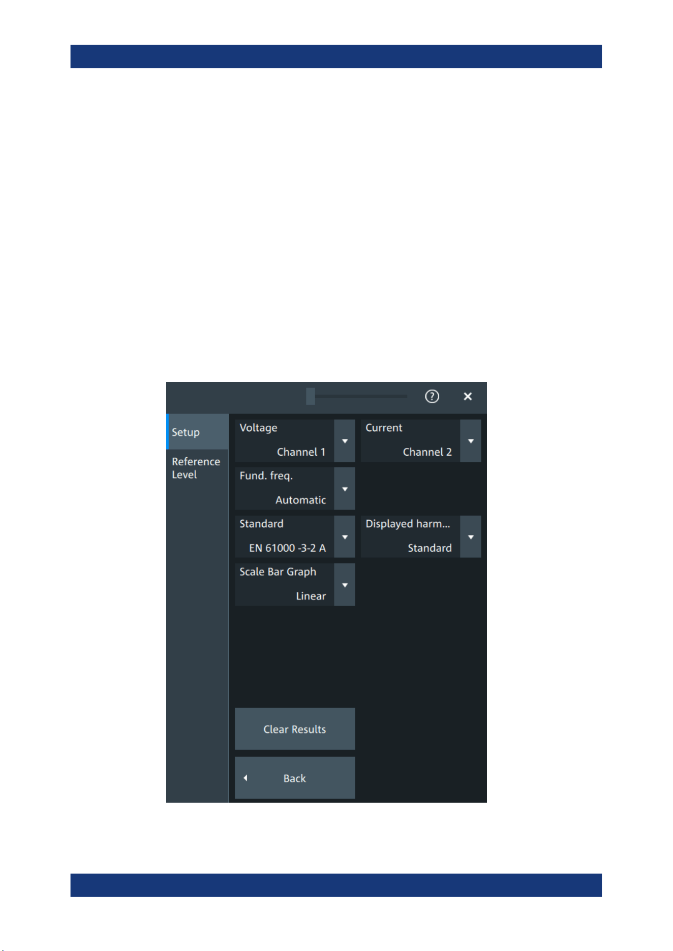
Applications
R&S
®
MXO 5 Series
256User Manual 1802.3369.02 ─ 02
a) Connect the positive (+) signal socket of the differential voltage probe to the
line of the AC input.
b) Connect the negative (-) signal socket of the differential voltage probe to the
neutral of the AC input.
c) Connect the current probe to the line of the AC input.
5. Select the correct channels for the "Voltage" and the "Current" probes.
6. Select the "Standard".
7. Select the "Fund. Freq" according to your signal.
On the screen, you can see the measurement of the current, the voltage and the
power. Also there is a table giving information about important measurement
parameters. For details, see "Power harmonic results" on page 258.
Power harmonic settings
In this tab, you configure the current harmonic measurement parameters and display
settings.
Power analysis (option R&S MXO5-K31)

Applications
R&S
®
MXO 5 Series
257User Manual 1802.3369.02 ─ 02
Voltage
Selects the channel for the voltage source.
Remote command:
POWer<m>:HARMonics:SOURce[:VOLTage] on page 629
Current
Selects the channel for the current source.
Remote command:
POWer<m>:HARMonics:SOURce:CURRent on page 628
Fund. Freq
Selects the frequency of the input signal. The available frequencies depend on the
selected Standard.
Remote command:
POWer<m>:HARMonics:FREQuency:EN on page 629
POWer<m>:HARMonics:FREQuency:MIL on page 630
POWer<m>:HARMonics:FREQuency:RTCA on page 630
Standard
Select the standard in use.
Table 11-1: Current harmonic precompliance standards
Standard Application
EN 61000-3-2 Class A Balanced 3-phase equipment, household appliances (excluding equip-
ment identified as class D), tools (excluding portable tools), dimmers for
incandescent lamps, audio equipment
EN 61000-3-2 Class B Portable tools, not professional arc welding equipment
EN 61000-3-2 Class C Lighting equipment
EN 61000-3-2 Class D PC, PC monitors, radio, or TV receivers with an input power less than or
equal to 600W
MIL-STD-1399 Military shipboard user equipment
RTCA DO-160 Environmental tests of avionics hardware
Remote command:
POWer<m>:HARMonics:STANdard on page 629
Displ. Harm.
Selects which harmonics are displayed in the bargraph: all, odd even or depending on
the standard definition.
Scale bar graph
Selects logarithmic or linear scale for the display for the harmonics bargraph.
Clear Results
Clears all current results and resets the statistics.
Power analysis (option R&S
MXO5-K31)
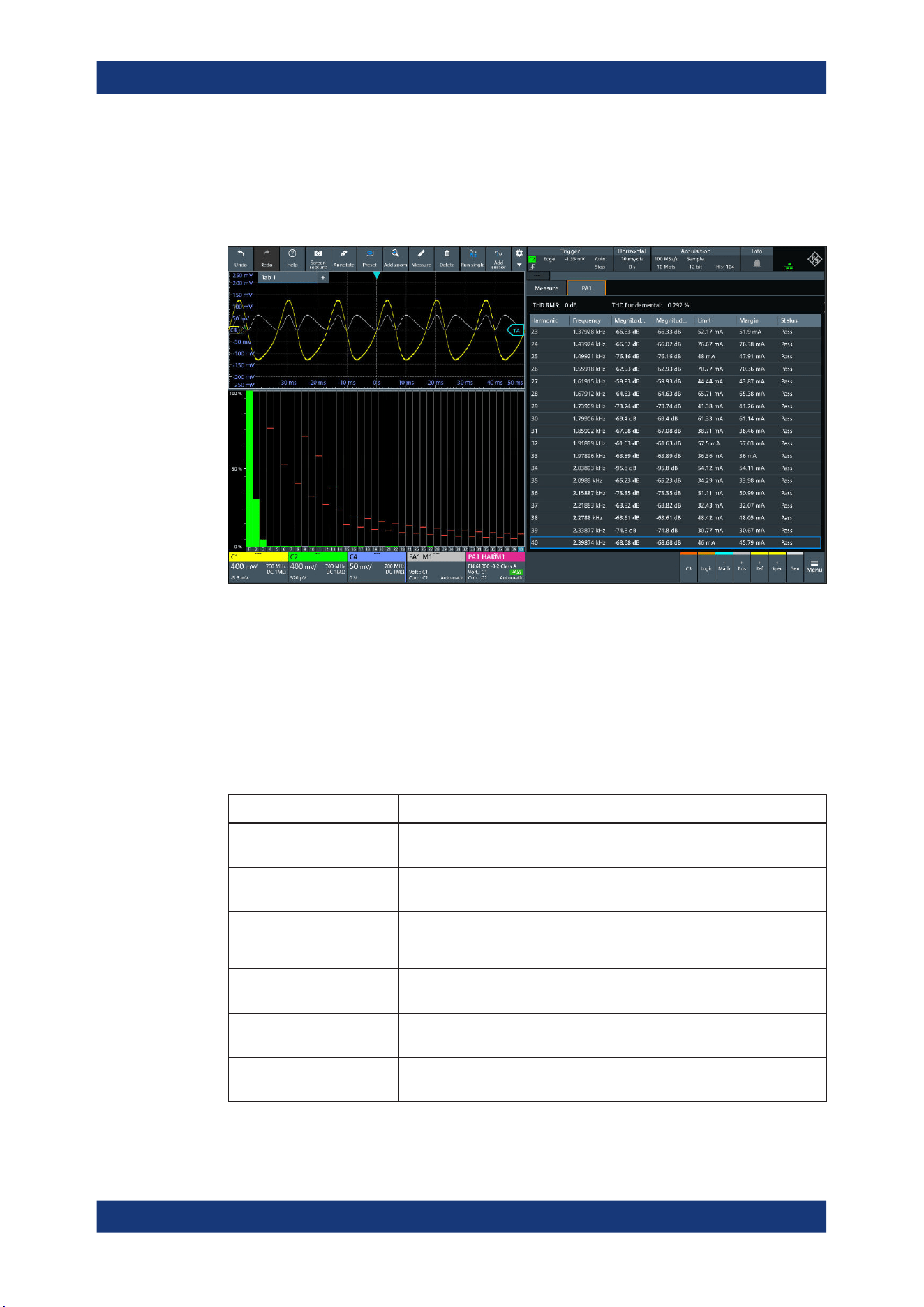
Applications
R&S
®
MXO 5 Series
258User Manual 1802.3369.02 ─ 02
Remote command:
POWer<m>:HARMonics:STATistics:RESet on page 630
Power harmonic results
The results of the Harmonic measurements are provided in two ways:
●
The diagram shows the graphical presentation of the voltage waveform, the current
waveform and the power waveform
●
The result box displays a bar chart and a table with the numerical measurement
results. The number of displayed harmonics depends on the standard definition.
When you tap on a harmonic in the bar chart, the respective row in the result box is
displayed.
The current harmonic results displayed in the result box are defined as follows:
Result table Bar chart match Description
THDF - Total harmonic distortion relative to the fun-
damental
THDR - Total harmonic distortion relative to the RMS
amplitude
Harmonic index Value of the x-axis The harmonic order
Frequency - The frequency value of the signal
Magnitude Value of the y-axis. Shown
by a green bar
The present value of the current harmonic
Magnitude (dB) Max Shown by a darkened green
bar
The maximum measured value
Limit Shown by a red bar The maxim allowed value according to the
selected standard
Power analysis (option R&S MXO5-K31)
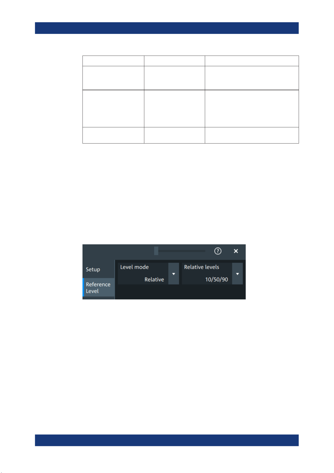
Applications
R&S
®
MXO 5 Series
259User Manual 1802.3369.02 ─ 02
Result table Bar chart match Description
Margin
Sets the upper limit for the display of the Y
scale.
This value can be reset with "Clear Results"
Status Pass: green bar
Dark orange bar: current
value
Light orange bar: maximum
value
Displays, if the harmonics is within the
defined limit (pass) or not (fail).
Blue outline of the row Blue bar The selected bar matches with the outlined
line in the result box.
Reference level
The power harmonic measurement requires reference levels to obtain the measure-
ment points. Power analysis uses its own reference level set, which is independent
from other measurements and is used for all power measurements. For a description
of the reference level settings, see Chapter 11.2.3, "Reference level", on page 259.
11.2.3 Reference level
Some power analysis measurements require reference levels to obtain the measure-
ment points. Power analysis uses its own reference level set, which is independent
from other measurements and is used for all power measurements.
Figure 11-4: Relative reference level
Power analysis (option R&S MXO5-K31)
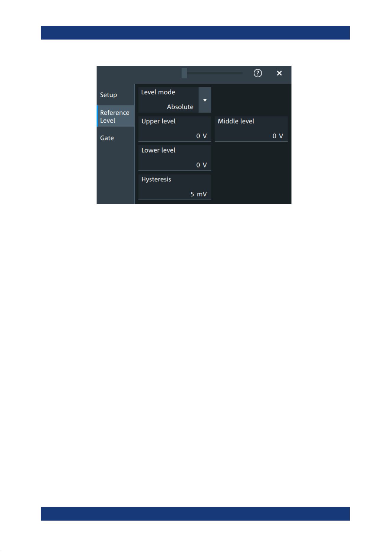
Applications
R&S
®
MXO 5 Series
260User Manual 1802.3369.02 ─ 02
Figure 11-5: Absolute reference level
Level mode
Defines if the reference level is set in absolute or relative values.
Remote command:
POWer<m>:HARMonics:REFLevel<rl>:LMODe on page 637
POWer<m>:QUALity:REFLevel<rl>:LMODe on page 637
Absolute Level mode
In the absolute mode, the reference values are set as voltages, in absolute values.
Upper level, Middle level, Lower level ← Absolute Level mode
Sets the low, middle and upper reference signal levels.
Remote command:
POWer<m>:HARMonics:REFLevel<rl>:ABSolute:LLEVel on page 636
POWer<m>:HARMonics:REFLevel<rl>:ABSolute:MLEVel on page 636
POWer<m>:HARMonics:REFLevel<rl>:ABSolute:ULEVel on page 636
POWer<m>:QUALity:REFLevel<rl>:ABSolute:LLEVel on page 636
POWer<m>:QUALity:REFLevel<rl>:ABSolute:MLEVel on page 636
POWer<m>:QUALity:REFLevel<rl>:ABSolute:ULEVel on page 636
Relative Level mode
In the relative mode, the reference values are set as percentages of the signal ampli-
tude.
Relative levels ← Relative Level mode
Selects the lower, middle and upper reference levels, defined as percentages of the
signal amplitude.
Available relative levels:
●
5/50/95
Power analysis (option R&S
MXO5-K31)

Applications
R&S
®
MXO 5 Series
261User Manual 1802.3369.02 ─ 02
●
10/50/90
●
20/50/80
●
User defined: Enter "Upper level", "Middle level", and "Lower level".
For example, for "5/50/95" the levels are set to the following values:
●
Lower level = 5% of the signal amplitude
●
Middle level = 50% of the signal amplitude
●
Upper level = 95% of the signal amplitude
Remote command:
POWer<m>:HARMonics:REFLevel<rl>:RELative:MODE on page 638
POWer<m>:QUALity:REFLevel<rl>:RELative:MODE on page 638
Upper level, Middle level,Lower level ← Relative Level mode
Define the reference levels in percent, if "Level mode" is set to "User-defined".
Remote command:
POWer<m>:HARMonics:REFLevel<rl>:RELative:LOWer on page 638
POWer<m>:HARMonics:REFLevel<rl>:RELative:MIDDle on page 638
POWer<m>:HARMonics:REFLevel<rl>:RELative:UPPer on page 639
POWer<m>:QUALity:REFLevel<rl>:RELative:LOWer on page 638
POWer<m>:QUALity:REFLevel<rl>:RELative:MIDDle on page 638
POWer<m>:QUALity:REFLevel<rl>:RELative:UPPer on page 639
Hysteresis
Defines a hysteresis for the middle reference level. A rise or fall from the middle refer-
ence value that does not exceed the hysteresis is rejected as noise.
Remote command:
POWer<m>:HARMonics:REFLevel<rl>:RELative:HYSTeresis on page 637
POWer<m>:HARMonics:REFLevel<rl>:ABSolute:HYSTeresis on page 635
POWer<m>:QUALity:REFLevel<rl>:RELative:HYSTeresis on page 637
POWer<m>:QUALity:REFLevel<rl>:ABSolute:HYSTeresis on page 635
11.2.4 Deskew
In the dialog box you can perform a deskew of your current and voltage probes.
Required equipment:
●
R&S RT-ZF20 power deskew fixture
●
Rohde & Schwarz voltage probe
●
Rohde & Schwarz current probe
Power analysis (option R&S
MXO5-K31)
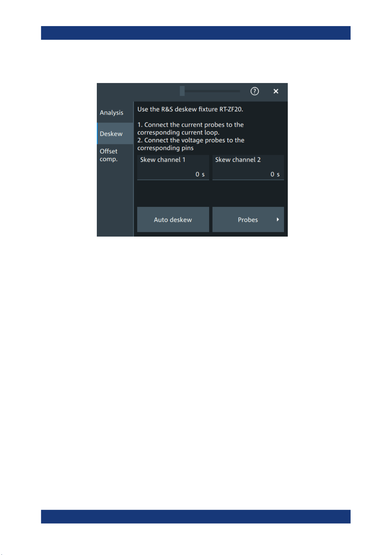
Applications
R&S
®
MXO 5 Series
262User Manual 1802.3369.02 ─ 02
11.2.4.1 Deskew settings
Skew channel
Sets user-defined skew settings for the channel connected to the current probe.
Alternatively, you can start an "Auto Deskew".
Auto Deskew
Starts an auto deskew. It is used to determine the trigger and scaling properties.
For an auto deskew, only Rohde & Schwarz probes are supported.
Make sure that the probes are configured correctly before you start the deskewing.
After the deskew, the result values are written in the "Skew" value of the corresponding
channel.
If there are more than two active channels, you can perform automatic deskew step by
step and exchange the probes connected fixture between the steps.
Remote command:
POWer<m>:ASKew[:EXECute] on page 620
11.2.5 Offset compensation
The offset compensation adjustments are applied to all power analysis measurements.
Power analysis (option R&S
MXO5-K31)

Applications
R&S
®
MXO 5 Series
263User Manual 1802.3369.02 ─ 02
Channel
Select the channel for the offset compensation.
AutoZero, Use AutoZero
Differences in DUT and oscilloscope ground levels can cause larger zero errors, which
affect the waveform. If the DUT is ground-referenced, the AutoZero function corrects
the zero error of the probe to optimize measurement results at small signal levels. The
validation limit depends on the probe attenuation because probes with high attenuation
often have to compensate high offsets. AutoZero detects offset values even when the
signal is out of the current measurement range.
To correct the zero error of voltage probes, short the signal pin and the ground pin
together and connect them to the ground of the DUT. Then tap "AutoZero". While the
alignment is running, the instrument switches to DC coupling to display the waveform
correctly.
To include the measured offset in measurement results, enable "Use AutoZero".
If a current probe is connected, the function demagnetizes the probe's sensor head
and sets the waveform to zero position.
Remote command:
PROBe<ch>:SETup:OFFSet:AZERo on page 479
PROBe<ch>:SETup:OFFSet:USEautozero on page 479
11.3 Digital voltmeter
The software-based voltmeter features AC RMS, DC and DC RMS voltage measure-
ments on a specific analog channel.
11.3.1 Using the digital voltmeter
To start a digital voltmeter measurement
1. Tap the "Menu" > "Apps" > "General" tab > "DVM", to open the digital voltmeter
measurement dialog.
Digital voltmeter
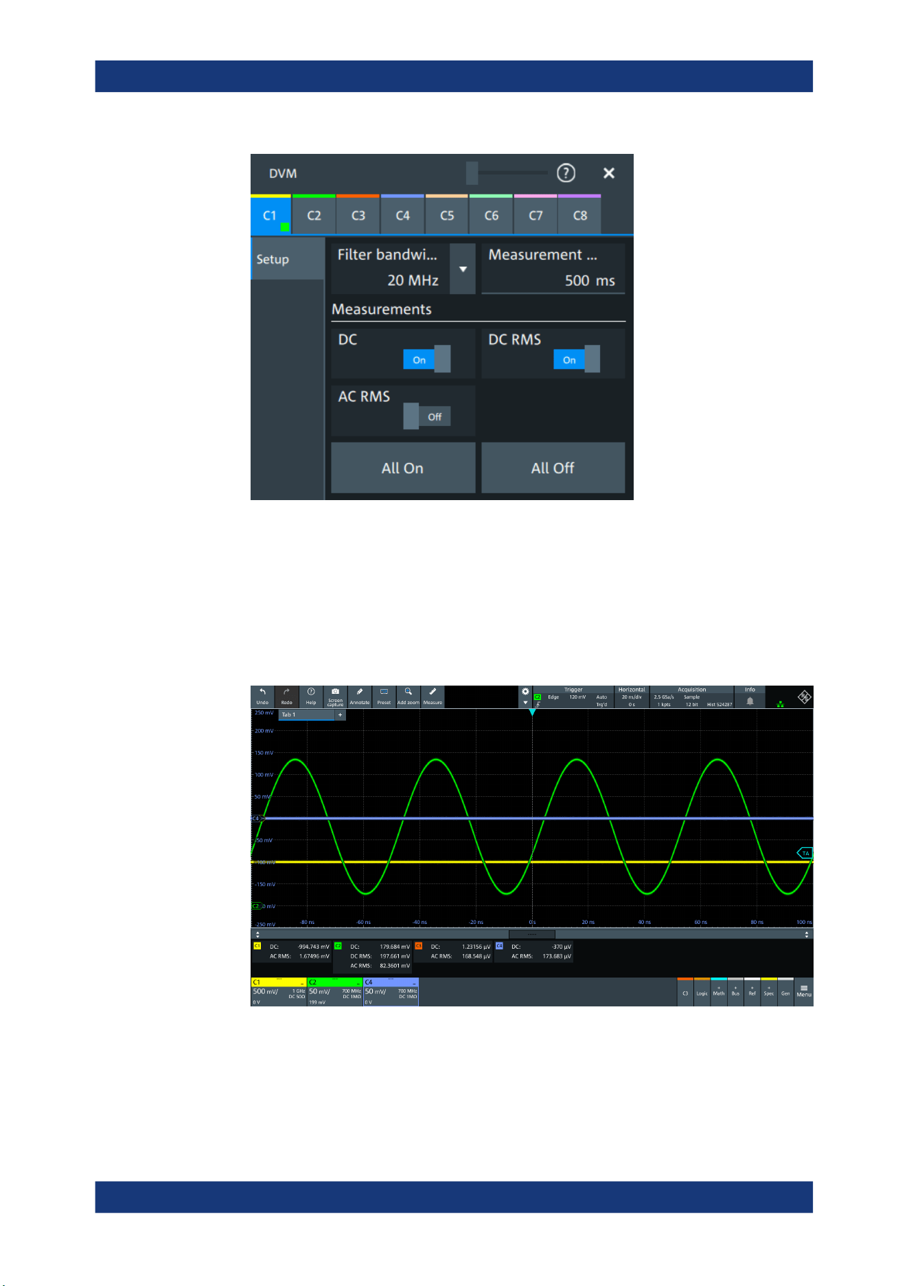
Applications
R&S
®
MXO 5 Series
264User Manual 1802.3369.02 ─ 02
2. Select the channel for your measurement.
3. Select a "Filter bandwidth" from the list.
4. Set a "Measurement time".
5. Tap on a measurement to enable it. Available are "DC", "DC RMS", "AC RMS".
The measurement results of all enabled measurements are displayed in a result
box.
11.3.2 Settings of the digital voltmeter
Access: "Menu" > "Apps" > "General" tab > "DVM".
Digital voltmeter
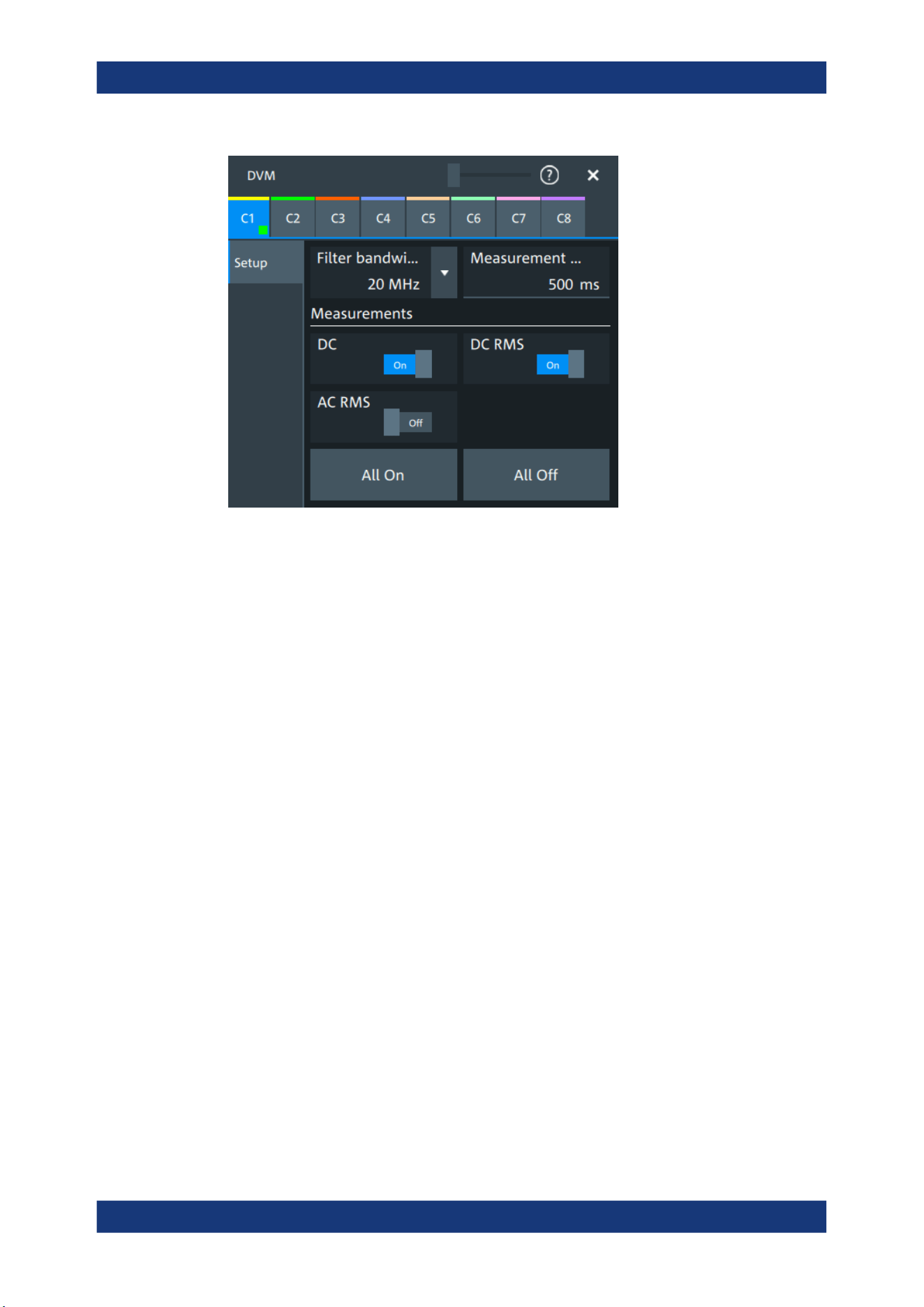
Applications
R&S
®
MXO 5 Series
265User Manual 1802.3369.02 ─ 02
C<n>
Selects the channel which is measured by the digital voltmeter.
Filter bandwidth
Selects the filter bandwidth.
Remote command:
METer:BANDwidth on page 642
Measurement time
Sets a measurement time. The time begins in the moment that a measurement is
enabled.
Measurements
Enables the voltmeter measurements. When a measurement is enabled, the voltmeter
is turned on automatically.
"DC"
Enables the DC voltage measurement.
"DC RMS"
Enables the DC RMS voltage measurement.
"AC RMS"
Enables the AC RMS voltage measurement.
Remote command:
METer:DVMeter<m>:ACRMs:ENABle on page 642
METer:DVMeter<m>:ACRMs:RESult? on page 642
METer:DVMeter<m>:DC:ENABle on page 643
METer:DVMeter<m>:DC:RESult? on page 643
METer:DVMeter<m>:DCRMs:ENABle on page 643
METer:DVMeter<m>:DCRMs:RESult? on page 644
All on, All off
Enables/disables all voltmeter measurements.
Digital voltmeter
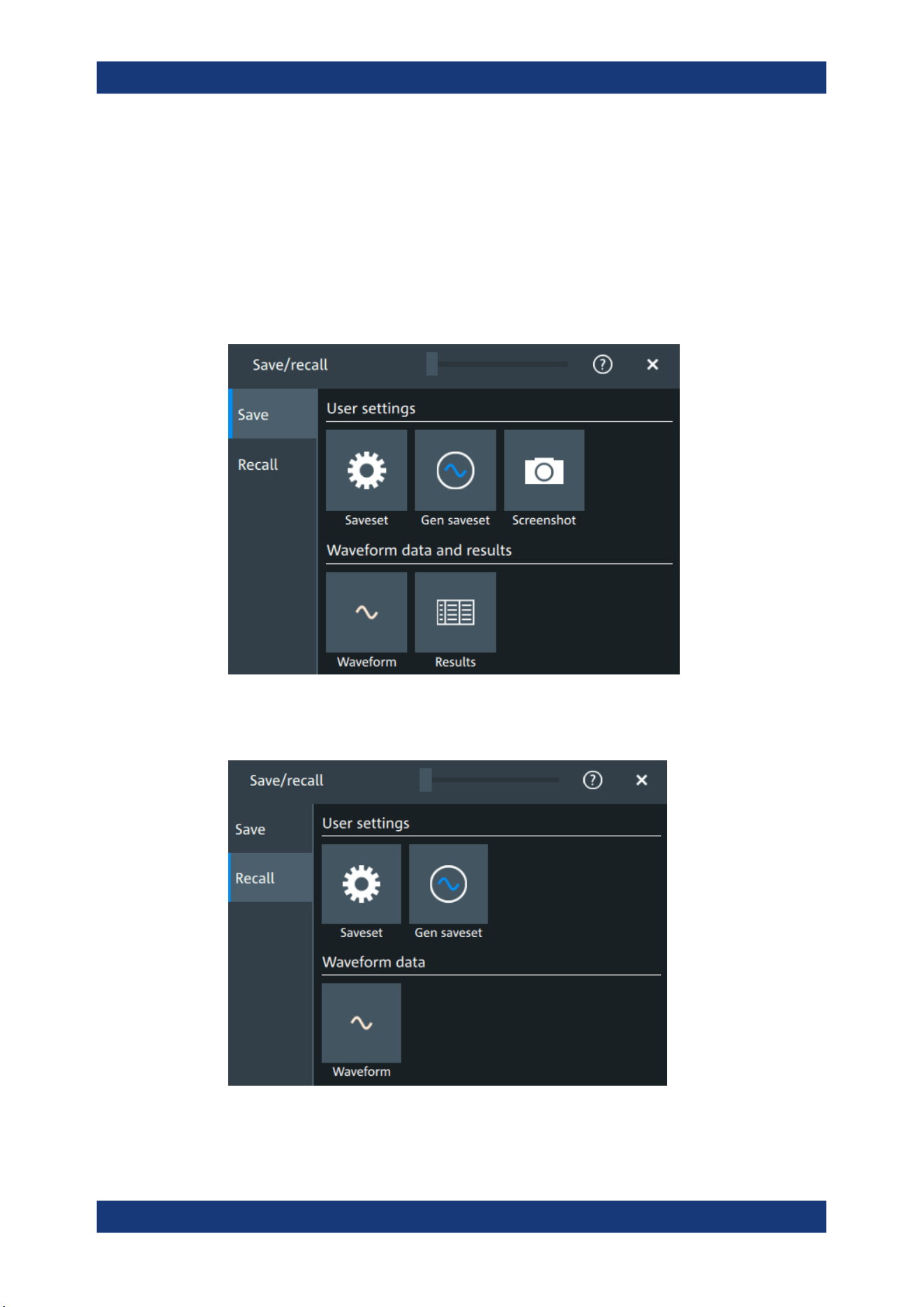
Data and file management
R&S
®
MXO 5 Series
266User Manual 1802.3369.02 ─ 02
12 Data and file management
This chapter describes how to manage instrument settings, waveform data, measure-
ment results, and screenshots.
The "Save/Recall" dialog provides functions for saving and restoring data on the instru-
ment.
Access to saving settings and data: "Menu" key > "Save/Recall" key > "Save" tab.
Figure 12-1: Save tab
Access to loading settings and data: "Menu" key > "Save/Recall" key > "Recall" tab.
Figure 12-2: Recall tab

Data and file management
R&S
®
MXO 5 Series
267User Manual 1802.3369.02 ─ 02
Using the "Save/Recall" dialog, you can store or load various data to files for further
usage, analysis and reporting:
●
Instrument settings: Chapter 12.1, "Save and recall user settings", on page 267
●
Waveforms: Chapter 12.2, "Save and recall waveform data", on page 271
●
Screenshots: Chapter 12.4, "Screenshots", on page 280
●
Reference waveforms: Chapter 12.2, "Save and recall waveform data",
on page 271 and Chapter 8.4, "Reference waveforms", on page 176
●
Measurement results: Chapter 12.3, "Saving results", on page 279
The [Camera] key can be configured to save or set up screenshots.
Storage locations
You can store data directly on the instrument, or to a USB flash drive. For local stor-
age, the path is always home/storage/userData. The path has subdirectories to
organize the data. For storage on USB flash drive, the default path
is /run/media/usb/. On both storage media, you can create directories to organize
the data. You can also copy, paste and delete data.
On USB flash drives, the following file systems are supported: FAT32 and NTFS.
12.1 Save and recall user settings
To repeat measurements at different times or perform similar measurements with differ-
ent test data, you can save the used instrument settings and load them again later.
Furthermore, you can refer to the instrument settings of a particular measurement
when analyzing the results. Optionally, the current toolbar and dialog configuration can
be included into the saveset.
Access: "Menu" key > "Save/Recall" key > "Save" tab > "User settings".
If you often save and load instrument settings, try the following shortcuts:
●
The "Save setup" toolbar icon saves the current settings to a file according to the
settings in "Save/Recall" key > "Save".
●
The "Recall" toolbar icon opens the dialog to select and load a setup.
●
You can assign a saveset to the [Preset] key and the "Preset" function on the tool-
bar, see Chapter 5.6, "Preset setup", on page 88.
12.1.1 Using savesets
Savesets contain the complete instrument and measurement configuration. You can
save an unlimited number of setting files.
To save settings to a saveset file
1. Open "Menu" > "Save/Recall".
2. In the "Save" tab, tap the "Saveset" button.
Save and recall user settings
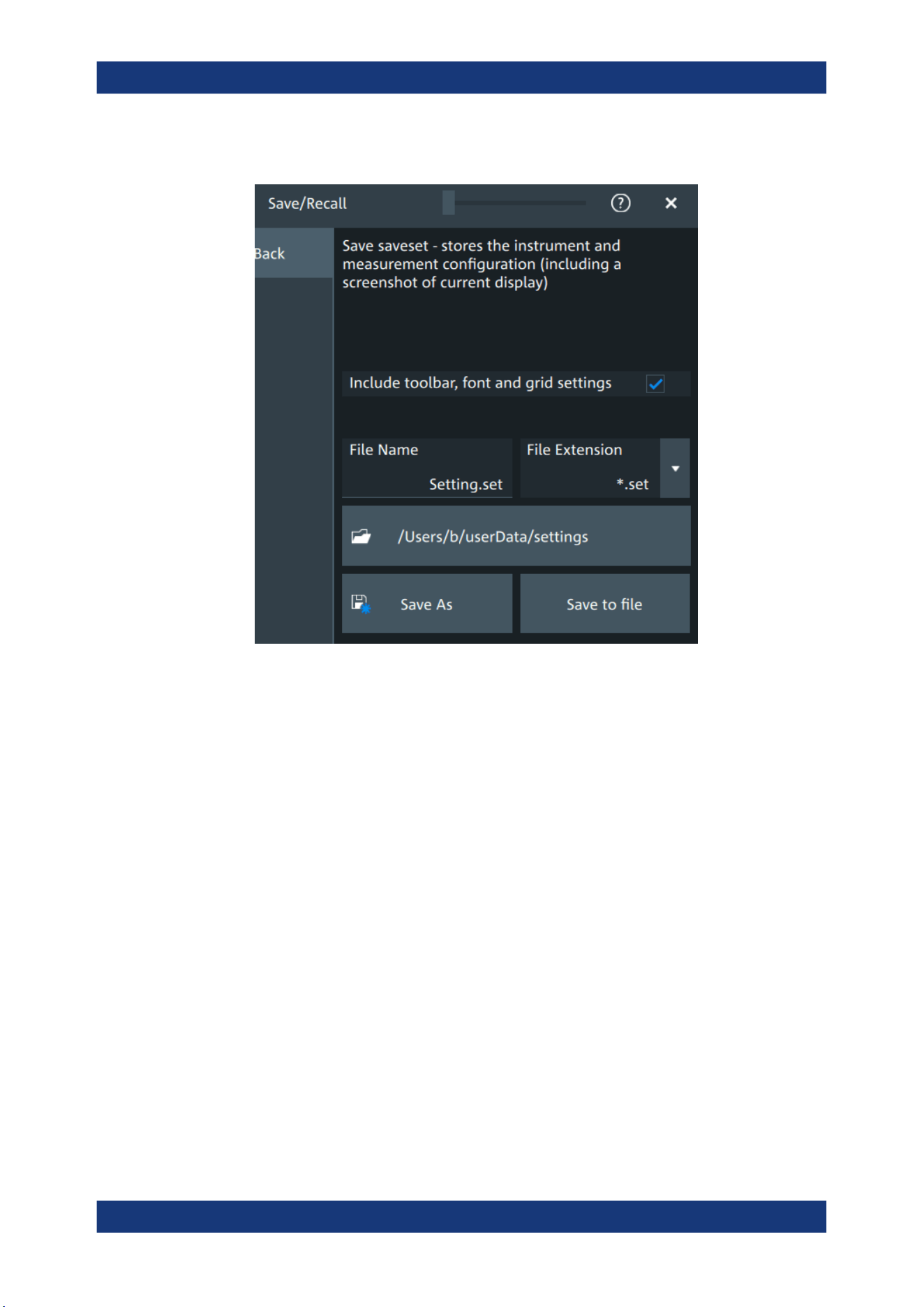
Data and file management
R&S
®
MXO 5 Series
268User Manual 1802.3369.02 ─ 02
The save "Saveset" dialog opens.
Figure 12-3: Save saveset dialog
3. If needed, enable "Include toolbar, font and grid settings".
4. Check the path on the "Directory" button. If the path does not fit, tap the button.
Navigate to the folder, where you want to save the settings file.
5. Tap "Save to file".
Alternatively, select "Save As" and select the destination folder and file name in the
file selection dialog.
The current settings are saved to the selected file.
To load settings from a saveset file
1. Open "Menu" > "Save/Recall".
2. In the "Recall" tab, press the "Saveset" button.
The recall "Saveset" dialog opens.
Save and recall user settings
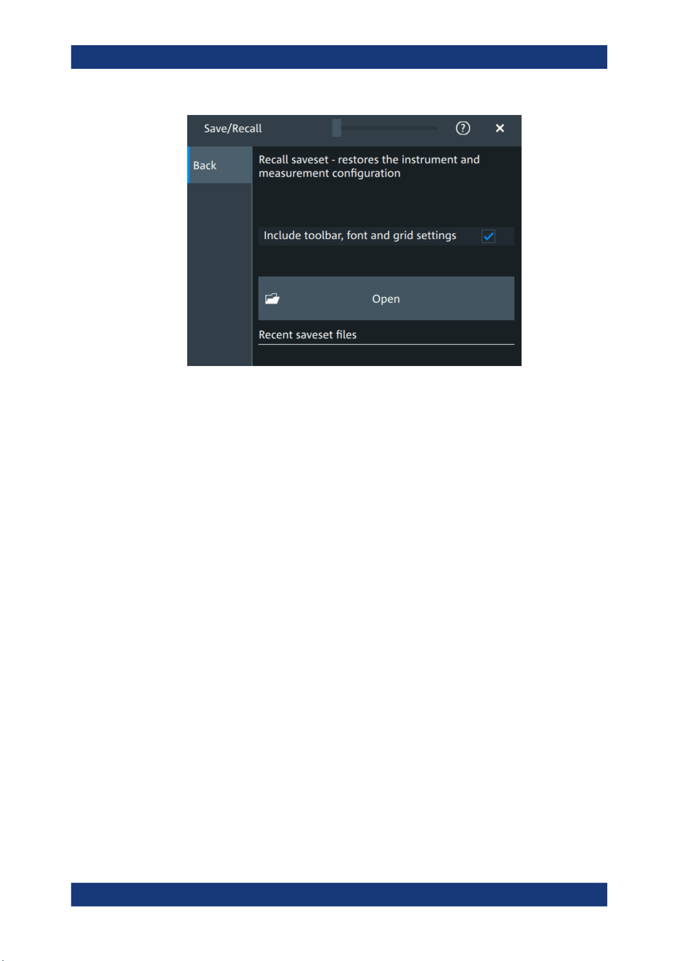
Data and file management
R&S
®
MXO 5 Series
269User Manual 1802.3369.02 ─ 02
Figure 12-4: Recall saveset dialog
3. Tap "Open".
4. Navigate to the required saveset.
The saved settings are loaded to the R&S MXO 5.
12.1.2 Gen saveset
Generator savesets store the instruments generator configuration.
To save settings to a saveset file
1. Open "Menu" > "Save/Recall".
2. In the "Save" tab, press the "Gen saveset" button.
The save "Gen saveset" dialog opens.
Save and recall user settings
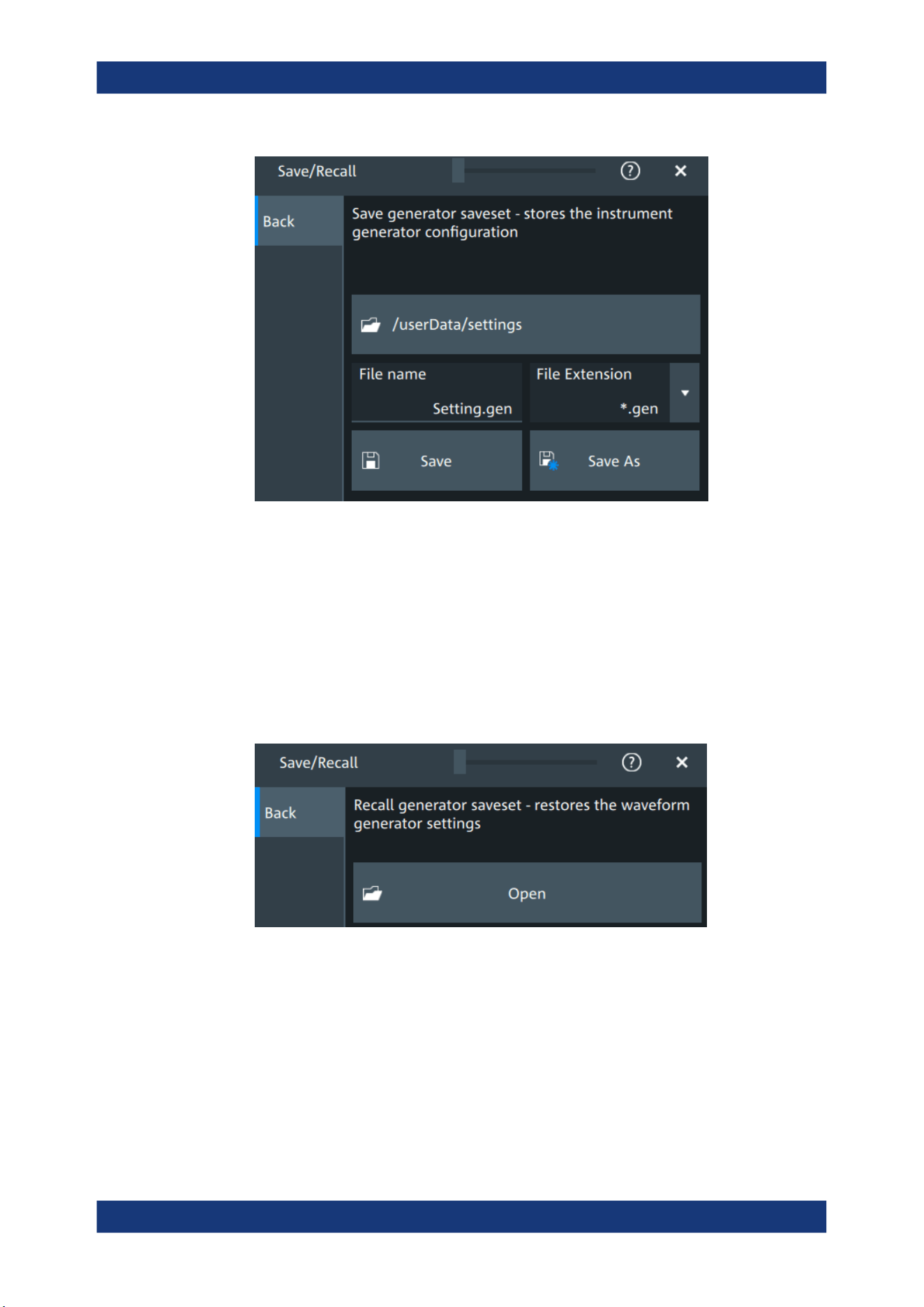
Data and file management
R&S
®
MXO 5 Series
270User Manual 1802.3369.02 ─ 02
Figure 12-5: Save generator saveset dialog
3. Tap "Browse"
The current settings are saved to the selected file.
To load settings from a saveset file
1. Open "Menu" > "Save/Recall".
2. In the "Recall" tab, press the "Gen saveset" button.
The recall "Gen saveset" dialog opens.
Figure 12-6: Recall generator saveset dialog
3. Tap "Open".
4. Navigate to the saveset.
The saved settings are loaded to the R&S MXO 5.
Remote commands:
●
GENerator:SAV on page 550
Save and recall user settings
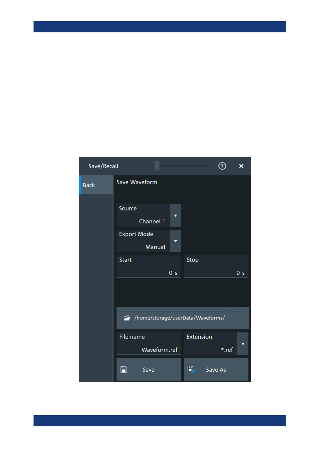
Data and file management
R&S
®
MXO 5 Series
271User Manual 1802.3369.02 ─ 02
●
GENerator:RCL on page 550
12.2 Save and recall waveform data
You can save waveform data to file, and reload the data of REF files as reference
waveforms.
12.2.1 Waveform settings
Access: "Menu" > "Save/Recall" > "Save" tab > "Waveform".
In this dialog, you define the storage settings for waveform data.
Save and recall waveform data

Data and file management
R&S
®
MXO 5 Series
272User Manual 1802.3369.02 ─ 02
Source
Selects the waveform to be exported. The list shows all active waveform that can be
exported.
Remote command:
EXPort:WAVeform:SOURce on page 552
Export mode
Defines the part of the waveform record that has to be stored.
"Display"
Saves the waveform data that is displayed in the diagram.
"All data"
Saves the complete waveform record.
"Cursor"
Saves the data between the cursor lines if at least one cursor mea-
surement is defined for the source waveform. If several cursor sets
are defined, select the "Cursor set" to be used for export.
"Gate"
Saves the data included in the measurement gate if a gated mea-
surement is defined for the source waveform. Select the "Gate" to be
used for export.
"Manual"
Saves the data between user-defined "Start" and "Stop" values.
Remote command:
EXPort:WAVeform:SCOPe on page 551
EXPort:WAVeform:CURSorset on page 553
EXPort:WAVeform:GATE on page 553
EXPort:WAVeform:STARt on page 552
EXPort:WAVeform:STOP on page 553
Save settings
Defines the details of the filename, extension and directory.
"File name"
Sets a name for the file, without extension.
"Extension"
Selects the format of the exported file.
You can select between "Excel-CSV-File (*.csv)" and a "Reference
Waveform Format (*.ref)". REF files can be reloaded as reference
waveforms. See also: Chapter 12.2.3, "Waveform export files",
on page 274.
"Directory"
Opens a file explorer where you can select the directory where the
file is saved.
"Save as"
Opens a file explorer where you can select the directory and enter the
filename.
"Save"
Saves the file in the defined "Directory" using the defined "File name".
If the specified file already exists, it is overwritten with the new data.
A progress bar informs you about the process, see "Progress information" on page 66.
Remote command:
EXPort:WAVeform:NAME on page 551
EXPort:WAVeform:SAVE on page 551
Save and recall waveform data
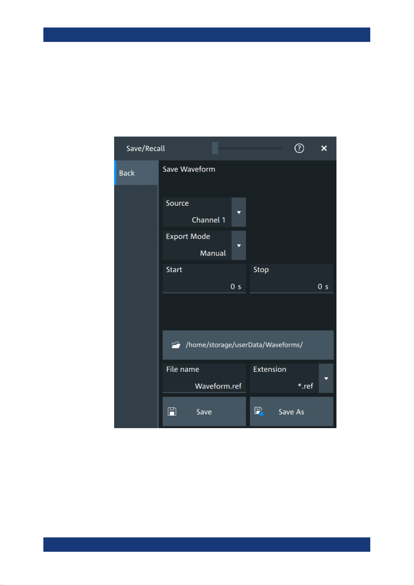
Data and file management
R&S
®
MXO 5 Series
273User Manual 1802.3369.02 ─ 02
12.2.2 Saving waveforms
To save a waveform
1. Open "Menu" > "Save/Recall".
2. In the "Save" tab, tap "Waveform".
Figure 12-7: Save waveform dialog
3. Select the "Source".
4. Select the "Export mode" to define the part of the waveform to be exported.
5. If necessary, define the cursor, gate or start/stop values for the data.
6. Select the format of the export file: "Extension".
Save and recall waveform data

Data and file management
R&S
®
MXO 5 Series
274User Manual 1802.3369.02 ─ 02
7. Set the "File name".
8. Tap "Save" or "Save as".
The current waveform is saved to the selected file. A progress bar informs you
about the saving process.
12.2.3 Waveform export files
Waveform data is stored in excel *csv format, or in a specific *.ref format. Files in
*.ref format can be reloaded as reference waveforms.
12.2.3.1 CSV files
A *csv file is a comma-separated values (CSV) text file, the waveform is stored in a
table. The columns are separated by commas. For each sample, one line is written.
Values are listed in scientific notation. You can convert the comma-separated text to
columns.
Content of waveform files
The first lines of the file contain header data, for example, time scale, vertical scale,
vertical and horizontal positions. Header data is required to interpret the waveform
data, and to analyze the data values of the data file.
Below the header, the waveform data follows. For each sample, one line is written. The
first value is the X-value (time or frequency), the next is the Y-value in the unit indicated
in the header data. For envelope or peak detect waveforms, two Y-values (minimum
and maximum) are written for each sample.
Save and recall waveform data
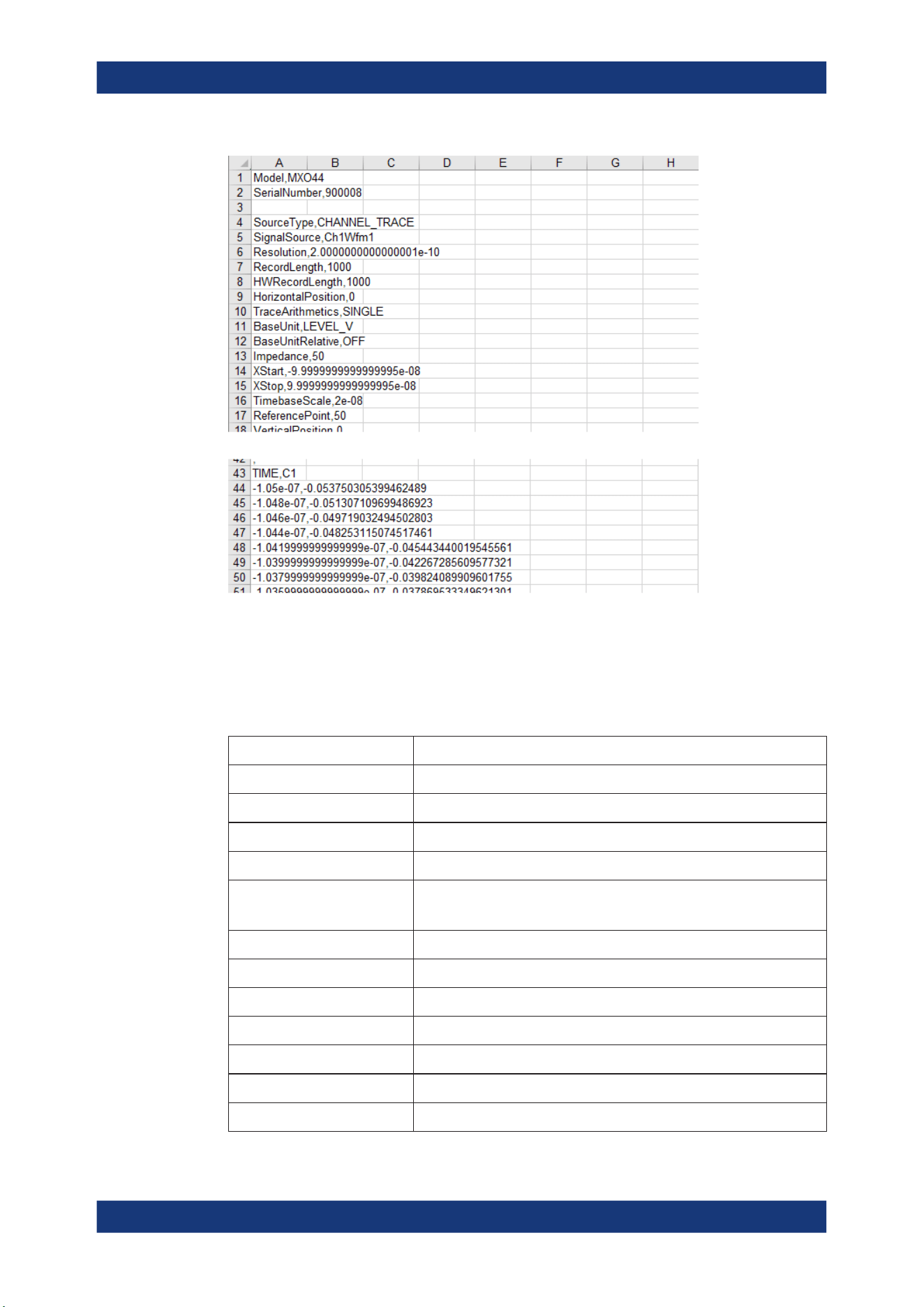
Data and file management
R&S
®
MXO 5 Series
275User Manual 1802.3369.02 ─ 02
Figure 12-8: CSV file, opened in Excel
Header data
The header lines contain the following properties:
Table 12-1: Header file properties in CSV files
Value Description
Model Model of the instrument
SerialNumber Serial number of the instrument
SourceType Type of the exported waveform
SignalSource Source of the exported waveform
Resolution Time between two samples
Resolution = 1 / Sample Rate
RecordLength Number of samples in a waveform record of one acquisition
HWRecordLength Equivalent to the RecordLength
HorizontalPosition Horizontal position of the waveform in divisions
TraceArithmetics Waveform arithmetic of the waveform: off, envelope, or average
BaseUnit Base unit of a mathematic waveform, for example, linear unit
BaseUnitRelative Base unit, if a relative unit (e.g. dB) is enabled
Impedance Input impedance, used for power calculation
Save and recall waveform data

Data and file management
R&S
®
MXO 5 Series
276User Manual 1802.3369.02 ─ 02
Value Description
XStart Horizontal start value of the waveform (time or frequency), as defined in
the export settings
XStop Horizontal stop value of the waveform (time or frequency), as defined in
the export settings
TimebaseScale Horizontal scale in seconds per division
ReferencePoint Position of the zero point in % of the screen
VerticalPosition Vertical position of the waveform in divisions
VerticalScale Vertical scale of the waveform
VerticalOffset Vertical offset of the waveform in Volts, or other unit
BaseYStart Vertical start value of the waveform
BaseYStop Vertical stop value of the waveform
ViewUnit User-selected unit of a mathematic waveform, for example, logarithmic
unit for a spectrum. The value is only valid if the exported waveform is a
math waveform.
ViewUnitRelative Indication of a relative unit. It is true if the math waveform has the ViewU-
nit "dB", for example. The value is only valid if the exported waveform is
a math waveform.
ViewReferenceLevel Reference level for a relative unit. The value is only valid if the exported
waveform is a math waveform, and the unit is relative.
NumericFormat Number format of bus values and digital channel data (bit pattern format)
EnhancementMode Method to increase the sample rate if the required sample rate is higher
than the ADC sample rate.
InterpolationMode Interpolation method. The value is relevant when the enhancement mode
is interpolated time.
CenterFreq Center frequency of the spectrum
FreqSpan Frequency span of the spectrum
ResolutionBW Resolution bandwidth of the spectrum
FrequencyStart Start frequency of the spectrum
FrequencyStop Stop frequency of the spectrum
WindowType Window used for the spectrum computation
GateRBWCoupling Indication whether the record length or the resolution bandwidth is a con-
stant for the spectrum computation
HorizontalDivisionCount Number of horizontal divisions
VerticalDivisionCount Number of vertical divisions
FirmwareVersion Firmware version that is installed on the R&S MXO 5
XAxisMode Indicates a linear or logarithmic x-axis
Save and recall waveform data
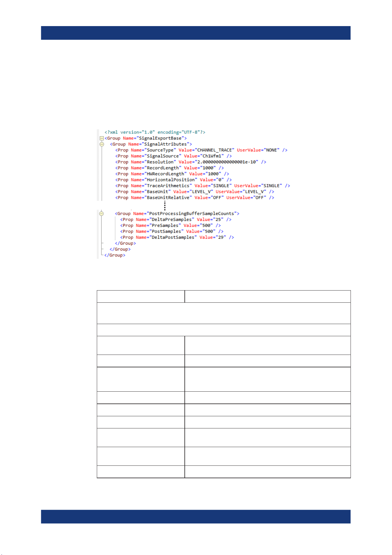
Data and file management
R&S
®
MXO 5 Series
277User Manual 1802.3369.02 ─ 02
12.2.3.2 Reference waveforms
The REF format is a specific format, which allows you to reload the waveform data as
reference waveform. The data is saved in a zipped file that contains two files. One file
is a binary file (BIN file) and contains the waveform data values. The second file is an
XML file and contains the header data in several data groups. Header data is required
to reload the waveform from data, or to analyze the data values of the data file.
Figure 12-9: Header file in XML format, part of the REF file container
Table 12-2: Header file properties in REF files
Value Description
SignalAttributes
Same values as in CSV files, except for Model and SerialNumber. See Table 12-1.
SignalAttributesPostProcessing
SignalFormat Format of the data values in the BIN file: INT8BIT, INT16BIT,
INT32BIT, FLOAT, DOUBLE
Origin WFM_EXPORT: export of one acquisition
ByteOrder
Byte order of the values in the BIN file
●
LSB first: little endian, least significant byte first
●
MSB first: big endian, most significant byte first
NumberOfWaveforms Number of waveforms, = 1
TimestampState OFF
Timestamp Absolute time of the waveform recording in ISO 8601 format
DecimationMode Method to reduce the number of data samples to achieve the
required sample rate
IsMinMax If ON, then min and max values are saved for each sample. For
envelope and peak detect waveforms.
IsComplex If ON, then two values are saved for each sample (I and Q value).
Save and recall waveform data

Data and file management
R&S
®
MXO 5 Series
278User Manual 1802.3369.02 ─ 02
Value Description
TriggerOffsetToPostSampleInSec-
onds
Offset between the exact trigger position and the first sample after
the trigger
SignalRecordLength Number of samples in the BIN file. If the signal is a spectrum, the
value indicates the number of FFT bins.
SignalXStart Time of the first sample in the acquired data. Different from XStart if
only part of the data is exported.
SignalXStop Time of the last sample in the acquired data. Different from XStop if
only part of the data is exported.
AdjustedResolutionBW Actual resolution bandwidth of a spectrum waveform. Only valid if the
exported waveform is a spectrum.
NoiseBandwidth Noise bandwidth of a spectrum waveform, required for power calcu-
lation. Only valid if the exported waveform is a spectrum.
ValuesPerSample Number of y-values saved at each sampling time. The value is usu-
ally 1. The value is 2, if min and max values are saved for each sam-
ple, for example, for envelope waveforms.
NofQuantisationLevels Number of quantization levels of y values
TOADone If ON, then TriggerOffsetToPostSampleInSeconds is compensated.
SignalResolution Time between two samples in this waveform. The value can differ
from Resolution if the source is, for example, a spectrum. The value
is determined automatically considering the waveform parameters
and their dependencies. If the signal is a spectrum, the value indi-
cates the frequency range of FFT bins.
HorizontalDomain Domain of the x-axis (TIME or FREQUENCY)
PostProcessingVerticalAxisAttributes
Range Range of the signal in y-direction
Offset Center of the y-range
Resolution Resolution of the y-axis
IsLogarithmic Indicates if the y-axis is logarithmic (ON or OFF)
PostProcessingSampleFormatAttributes
ValueStorage Interpretation of the data: is INTEGER or FLOAT (floating point data)
ValueInterpretation Indicates if the data is saved as binary ADC values (BINARY), or
physical values (PHYSICAL)
SampleBitSize Value size in bit, as used in processing
ValueBitSize Value size of ADC data in bit
LsbExtensionBits Number of bits the ADC value is shifted to the left in the CPU sample
size
AdcValueBitSize Number of bits of the ADC that was used to sample the signal. It
does not include any additionally gained bits due to high definition
mode.
IsSigned Signed values (ON) or unsigned values (OFF)
Save and recall waveform data
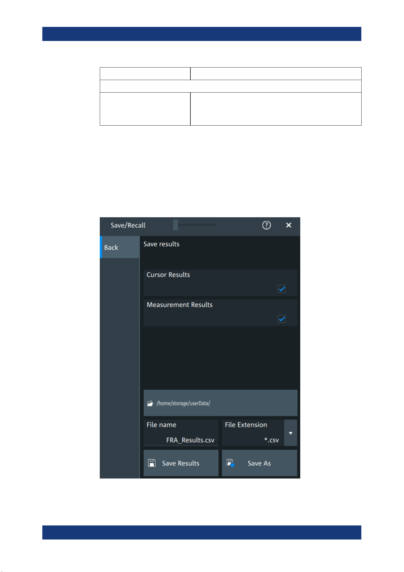
Data and file management
R&S
®
MXO 5 Series
279User Manual 1802.3369.02 ─ 02
Value Description
PostProcessingBufferSampleCounts
[DeltaPreSamples | PreSamples ||
PostSamples | DeltaPostSamples]
Indicates the distribution of the samples. || marks the trigger time.
The sum of PreSamples and PostSamples matches the requested
record length. DeltaSamples are additional samples that needed for
computation but they are not measured or displayed.
Note: FractionalBits was removed in FW version 1.3.x. Reference waveforms created
with older FW version are compatible and can be reloaded.
12.3 Saving results
In this tab, you can select the result tables to be saved, and define the storage set-
tings.
Saving results

Data and file management
R&S
®
MXO 5 Series
280User Manual 1802.3369.02 ─ 02
To save results
1. Open "Menu" > "Save/Recall".
2. In the "Save" tab, press the "Results" button.
The save "Results" dialog opens.
3. Select the results to be saved. The "Save results" results list shows all result tables
that are currently open. All results are written into one file.
4. Under "Location", enter a "File name" and select "Save". Alternatively, select "Save
As" and define the target directory and file name in the file selection dialog.
The current results are saved to the selected file.
Remote commands:
●
EXPort:RESult:SELect:CURSor on page 554
●
EXPort:RESult:SELect:MEASurement on page 554
●
EXPort:RESult:NAME on page 553
●
EXPort:RESult:SAVE on page 554
12.4 Screenshots
To store the graphical results of the measurement, you can save a screenshot of the
graphic area. To document current settings, the open dialog box can be included in the
screenshot.
If you often save screenshots, try the following shortcuts:
●
The "Screen capture" toolbar icon saves the current display to a file according to
the settings in "Menu" > "Save/Recall" > "Save" tab > "Screenshot".
●
You can configure the [Camera] key to save screenshots by a single keypress. See
also "Camera hardkey action" on page 87.
If a USB flash drive is connected to the instrument, the default path of the user data
directory is set to the USB flash drive. Thus, you save data to USB flash drive automat-
ically, and you can change the directory in the file explorer at any time.
Screenshots on a computer using the Web interface
If the R&S MXO 5 is connected to a LAN, you can create and save screenshots of the
instrument's display on a computer.
Meta information in screenshots
The meta data of the screenshot also contains instrument information. In PNG and
JPEG files, meta information is saved as EXIF information and can be read, for exam-
ple, using the ExifTool.
Screenshots
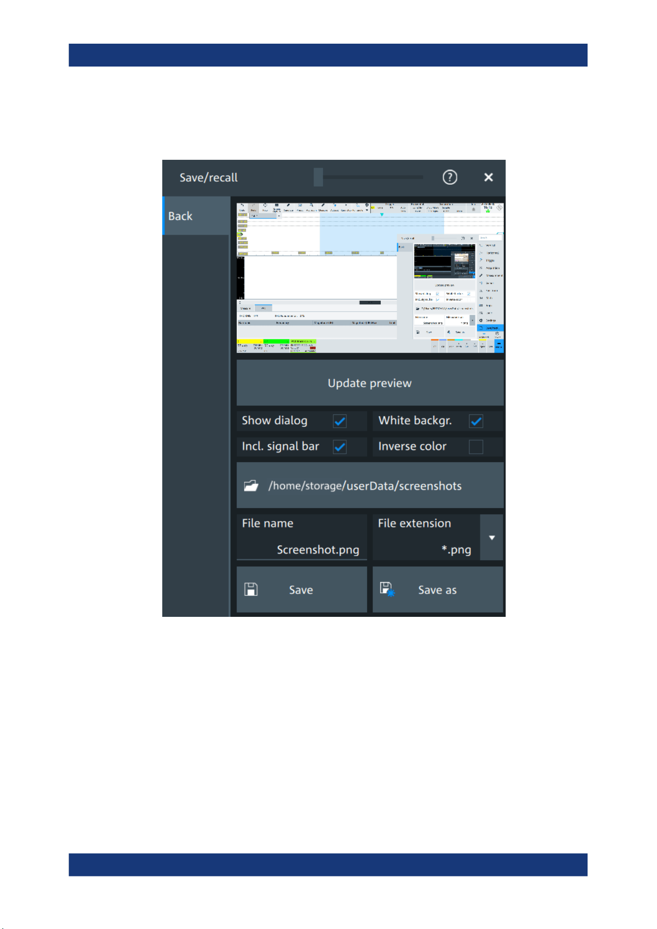
Data and file management
R&S
®
MXO 5 Series
281User Manual 1802.3369.02 ─ 02
12.4.1 Screenshot settings
Access: "Menu" > "Save/Recall" > "Save" tab > "Screenshot"
In the "Screenshot" dialog box, you configure the image to be saved or included in a
report. You select the storage location for screenshot files. The image is created when
you open the dialog box, and can be updated at any time.
You can also edit the colors of the image before saving it, and include an open dialog
box or the sidebar in the image.
You can save the image in the dialog box. To save screenshots quickly, use the
"Screen capture" toolbar icon, or configure and use the [Camera] key.
Preview....................................................................................................................... 282
Update.........................................................................................................................282
Show setup dialog.......................................................................................................282
White background....................................................................................................... 282
Screenshots

Data and file management
R&S
®
MXO 5 Series
282User Manual 1802.3369.02 ─ 02
Include signal bar........................................................................................................ 282
Inverse color................................................................................................................282
Directory......................................................................................................................282
File name, Extension...................................................................................................283
Save............................................................................................................................ 283
Preview
Shows a preview of the screenshot. The image is created when the dialog box opens.
Update
Updates the preview of the screenshot with the current display view, e.g. after changes
to the settings have been made, or an additional channel has been activated.
Show setup dialog
If enabled, the currently open dialog box is included in the screenshot.
Remote command:
HCOPy:SSD on page 557
White background
Inverts the background color, so you can picture waveforms with normal waveform col-
ors on white background.
If both "White background" and "Inverse color" are enabled, the instrument inverts the
background twice, and it appears black.
"White background" "Inverse color" Background Waveform and results
On Off White Screen colors
Off On White Inverted colors
On On Black Inverted colors
Off Off Black Screen colors
Remote command:
HCOPy:WBKG on page 557
Include signal bar
If enabled, the screenshot shows the signal bar below the diagram area.
Remote command:
HCOPy:ISBA on page 556
Inverse color
Inverts the colors of the output, i.e. a dark waveform is shown on a white background.
Remote command:
HCOPy:DEVice<m>:INVerse on page 555
Directory
Opens the file selection dialog box. Here you can adjust the target directory where the
screenshot is saved. The symbols of important target folders are listed on the left of the
file explorer.
Screenshots

Data and file management
R&S
®
MXO 5 Series
283User Manual 1802.3369.02 ─ 02
Remote command:
HCOPy:DESTination<m> on page 555
File name, Extension
Sets a file name for the screenshot, and the extension of the file. You can save the
screenshot as *.jpg or *.png file.
Save
Saves the current screenshot to the specified file.
12.4.2 Configuring and saving screenshots
You can select which elements are shown in the screenshot, invert the colors and the
background color. A preview of the current image is shown for reference.
1. Open the "Menu" > "Save/Recall" > "Save" tab > "Screenshot".
2. To enhance the images for later print on white paper, enable "White background" or
"Inverse color". If you print this image later on a monochrome printer, you get a
grayscaled picture. The contrast of the gray lines depends on waveform colors and
the used printer.
3. To change the directory, tap "Browse" and configure the path.
The symbols of often used target folders are listed on the left of the file explorer. By
default, screenshots are saved in the /home/storage/userData/
ScreenShots directory.
4. Tap "Save".
The file is saved.
5. Check if the screenshot is saved to the desired directory.
6. To save further screenshots, use one of the following ways:
● Configure the [Camera] key. Press the key to save a screenshot.
See also Camera hardkey action.
● Add the "Screen capture" icon to the toolbar. Tap the icon to save an image.
● Tap "Save" in the "Screenshot" dialog box to save the image to the specified
file.
● To save the image with a dedicated filename or to another directory, tap
"Browse" in the "Screenshot" dialog box.
Select the path, enter a filename, and tap "Save".
12.5 File browser dialog
The file browser dialog provides a file explorer from which you can select a file to load
or to save data to. You can also manage your files in this dialog.
File browser dialog

Data and file management
R&S
®
MXO 5 Series
284User Manual 1802.3369.02 ─ 02
Access: [Apps] > "File browser".
Path
Navigate the path elements to change the current folder. The default folder is defined
in Chapter 5.8.1, "Autonaming", on page 95.
You can save the data in a local folder on the instrument.
On the left, shortcut icons provide access to often used folders.
Toolbar
The toolbar on the top provides various functions for file management.
"Filter"
Displays only the files and folders that match the current search term.
"Delete"
Deletes the selected file or folder.
"New folder"
Creates new folder in the current directory.
"Rename"
Renames the selected file.
"Find"
Searches for files within the current folder.
"Copy"
Copies the selected file.
"Paste"
Pastes the file.
File name
The file name to be loaded or stored to. Tap the file name, or tap the keyboard icon to
enter the file name using the online keyboard.
The default file name for new files is defined in the "Autonaming" tab, see Chap-
ter 5.8.1, "Autonaming", on page 95.
File type
The file extension of the file to be loaded or stored to.
Save, Select
Selects the specified file for the open or save operation and closes the dialog box.
Cancel
Closes the dialog box without selecting a file.
File browser dialog
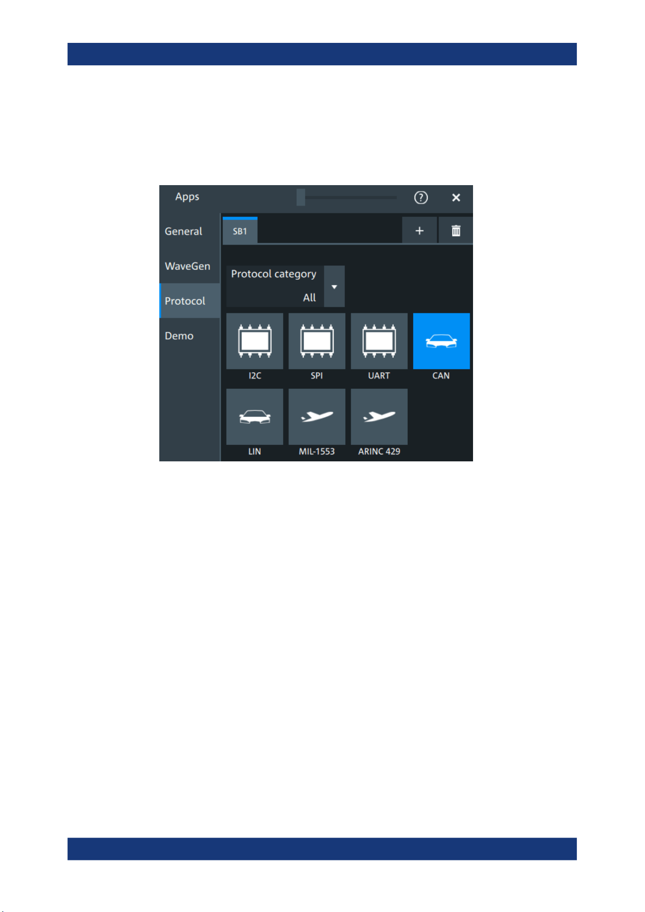
Protocol analysis
R&S
®
MXO 5 Series
285User Manual 1802.3369.02 ─ 02
13 Protocol analysis
Using the serial protocol options for the R&S MXO 5, you can analyze various serial
protocols.
● Basics of protocol analysis....................................................................................285
● SPI bus (option R&S MXO5-K510)....................................................................... 293
● I²C (option R&S MXO5-K510)...............................................................................309
● UART (option R&S MXO5-K510)..........................................................................326
● CAN (option R&S MXO5-K520)............................................................................ 340
● LIN (option R&S MXO5-K520).............................................................................. 365
13.1 Basics of protocol analysis
With the R&S MXO 5 oscilloscope, you can decode selected protocols.
With dual-path protocol analysis, you can set the instrument sample rate for the wave-
form path and the oscilloscope automatically uses another internal decoupled sample
rate for the decoding path. Even with very slow sample rates, the protocol data is cor-
rectly decoded.
With the R&S MXO 5, you can use deep memory to capture more packets. The oscillo-
scope can capture long time periods where the cause and result are distanced in time.
Over the entire capture, signal detail is time-correlated with packet content for fast
debug.
Basics of protocol analysis
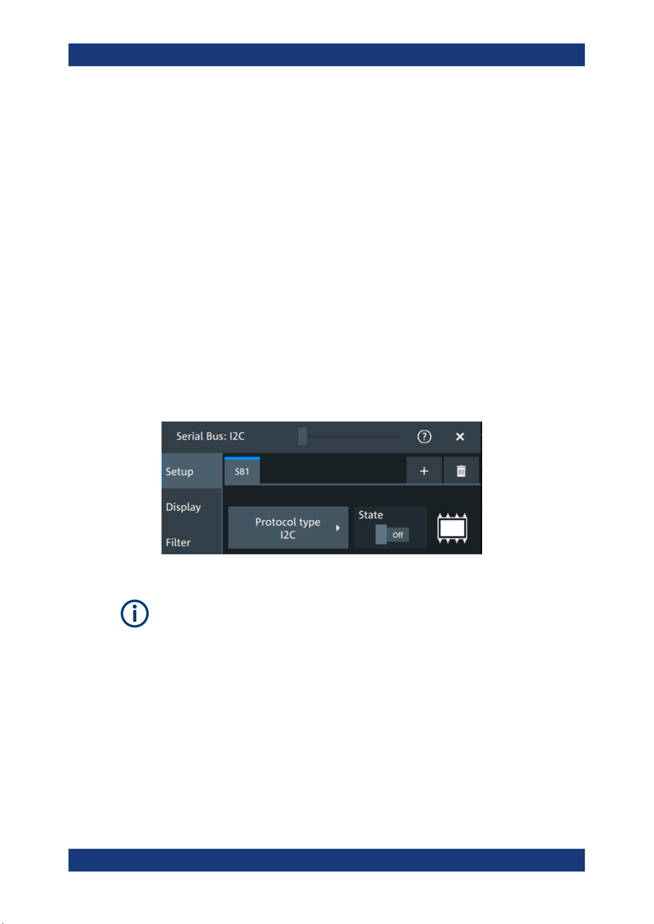
Protocol analysis
R&S
®
MXO 5 Series
286User Manual 1802.3369.02 ─ 02
Before you can analyze a serial signal, the bus has to be configured according to the
protocol and specifics of the signal. The configuration contains:
●
Assignment of the data and clock lines to the input channels
●
Logical thresholds
●
Protocol-specific settings
Serial data can be analyzed in several ways:
●
Triggering: You can trigger on various events that are typical for the selected proto-
col type, for example, on start and stop of messages, or on specified data patterns
in the message.
Triggering on a trigger event sequence is not supported, and holdoff settings are
not available.
●
Protocol decoding: The digitized signal data is displayed on the screen together
with the decoded content of the messages in readable form, and the decode
results are listed in a table.
13.1.1 Setup - general settings
For all protocols, configuration starts with the selection of the serial bus and the proto-
col.
Configuration settings are protocol-specific. They are described in the related chapters.
Make sure that the tab of the correct serial bus is selected.
SB1 /SB2 /SB3 /SB4
Select the correct bus tab before you enter the settings.
Protocol type
Displays the protocol type to be decoded.
Remote command:
SBUS<sb>:TYPE on page 645
State
Enables the decoding of the selected bus. The signal icon of the bus appears on the
signal bar.
Basics of protocol analysis
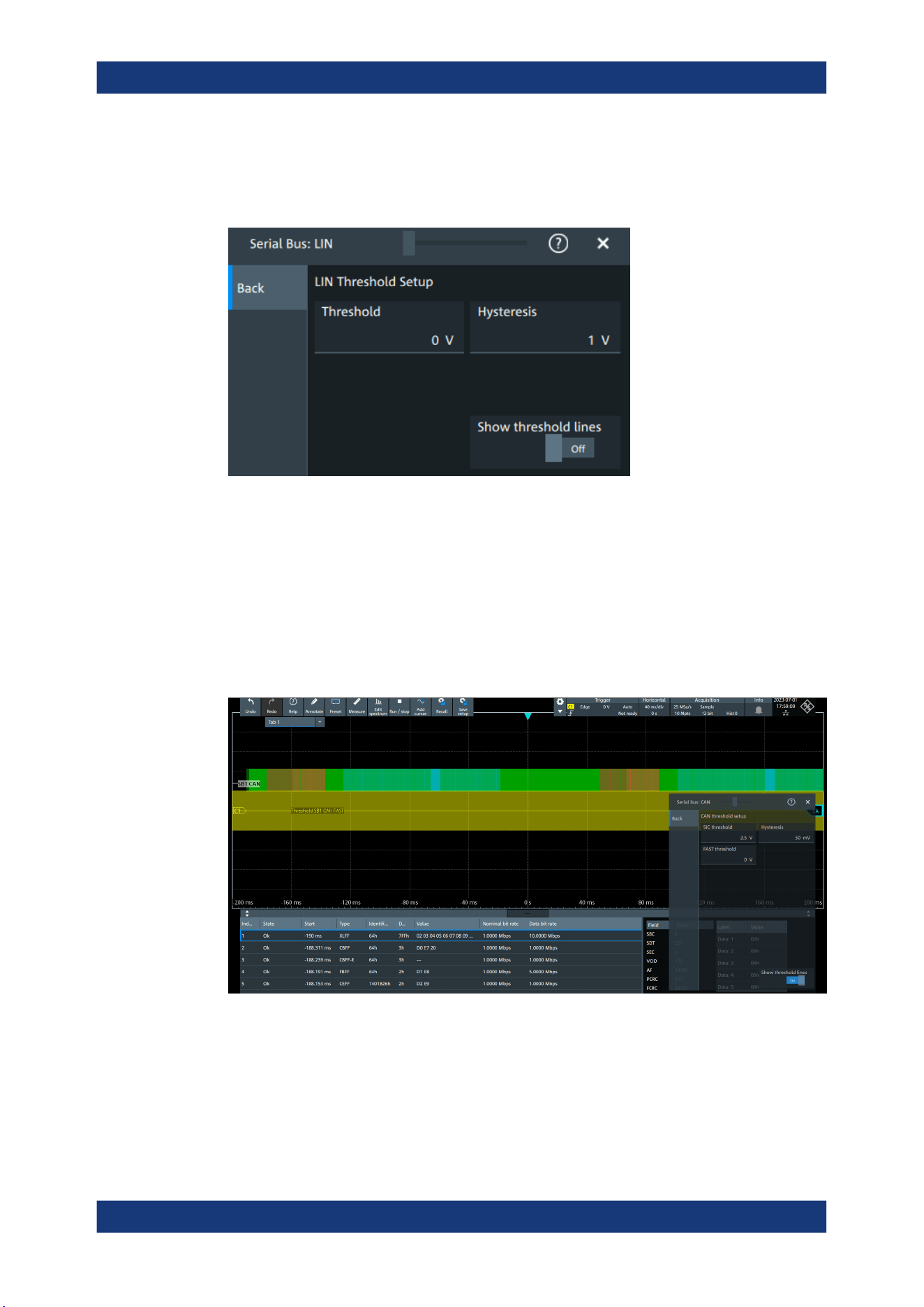
Protocol analysis
R&S
®
MXO 5 Series
287User Manual 1802.3369.02 ─ 02
Threshold
Press "Set thresholds", to open the "Threshold setup" dialog.
In the "Threshold setup" dialog, you can set values for threshold and hysteresis.
Show threshold lines ← Threshold
In the "Threshold" dialog, you can enable the display of the threshold lines in the dia-
gram.
The label of the threshold line is set according to the signal that it is referring to. It is
displayed in the color of the signal channel.
Example:
When the "Show threshold lines" is enabled, the threshold lines and the hysteresis are
shown on the display for a few seconds. Afterwards only the threshold line is visible.
Figure 13-1: Threshold lines, shortly after Show threshold lines is enabled
Remote command:
SBUS<m>:THReshold on page 646
Basics of protocol analysis
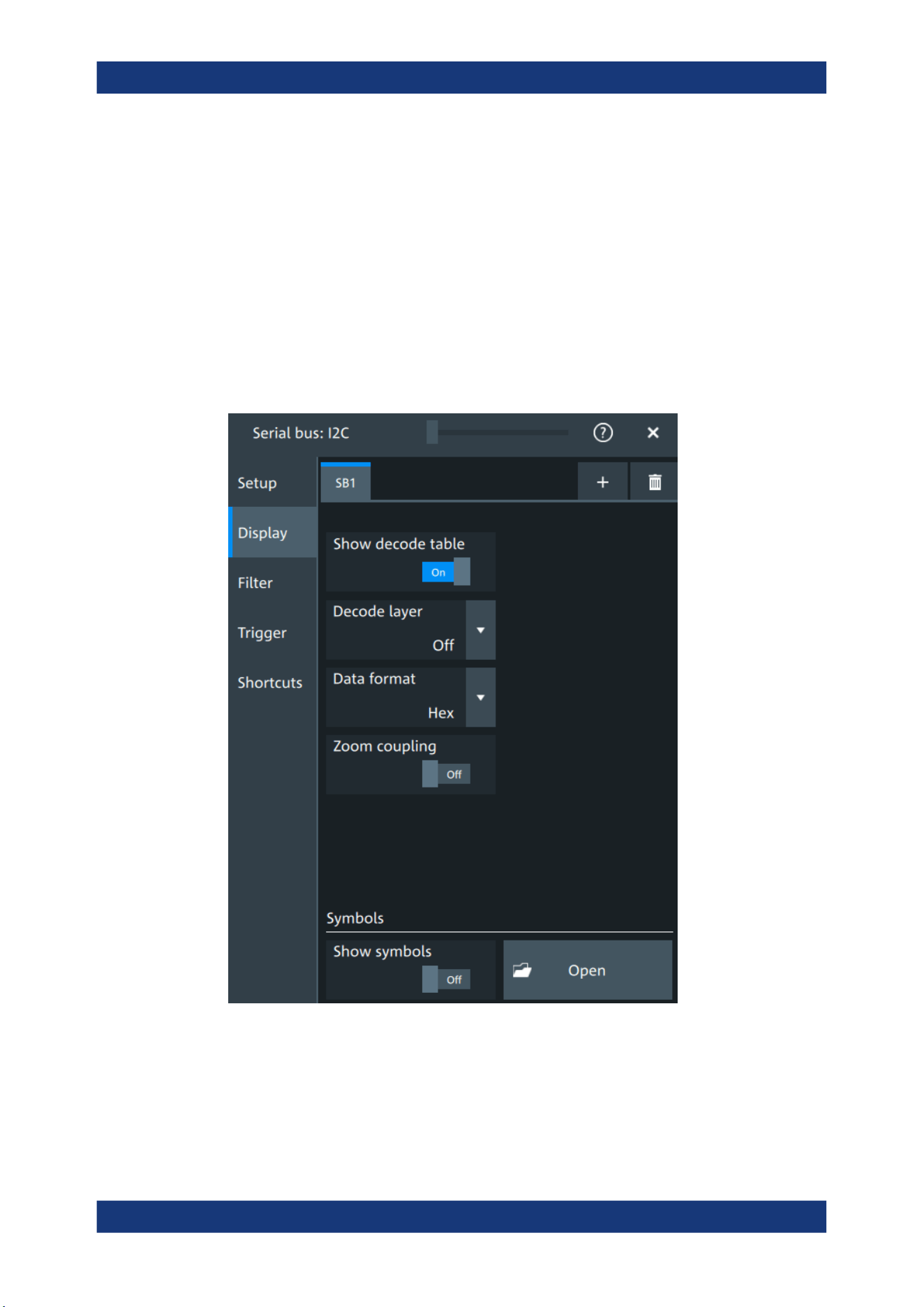
Protocol analysis
R&S
®
MXO 5 Series
288User Manual 1802.3369.02 ─ 02
13.1.2 Advanced
Some protocols have additional more advanced settings. They are displayed in the
"Advanced" tab.
The settings are protocol specific and are described in the corresponding protocol
chapter.
13.1.3 Display
For all protocols, you can select to display the decoded signal as a table and to show
the binary signal on the screen.
Show decode table
Opens a table with decoded data of the serial signal. The function requires the option
for the analyzed protocol.
Decode results are protocol-specific.
Basics of protocol analysis

Protocol analysis
R&S
®
MXO 5 Series
289User Manual 1802.3369.02 ─ 02
Remote command:
SBUS<sb>:RESult on page 645
Decode layer
Selects the decode layer.
Decoding is performed in several steps, and the results are presented in the decode
table. The decode layer selects an interim step for which the decoding result is shown
in the honeycomb display.
The available values are protocol-specific.
"Off"
No decode layer is displayed.
"Edges"
All edges.
"Bits"
All bits.
"Words"
All words.
Data format
Sets the data format for the values displayed in the decode table and in the combs of
the decoded signal.
Available formats are: hex, octal, binary, ASCii, signed, unsigned.
For more information on the available formats, see Chapter 13.1.8, "Bit pattern editor",
on page 292.
Remote command:
SBUS<sb>:FORMat on page 645
Zoom coupling
If enabled, the decode zoom and result table are synchronized. If you select a row in
the result table, this result is shown in the decode zoom.
Remote command:
SBUS<m>:ZCOupling on page 646
Symbols
Symbol lists are protocol-specific. They are described in the respective configuration
chapter of the protocol.
13.1.4 Filter
In the "Filter" tab, you can define the settings to display only the frames that match the
selected filter conditions.
The settings are protocol specific and are described in the corresponding protocol
chapter.
13.1.5 Trigger
The "Trigger" tab gives quick access to the "Trigger" dialog.
Basics of protocol analysis
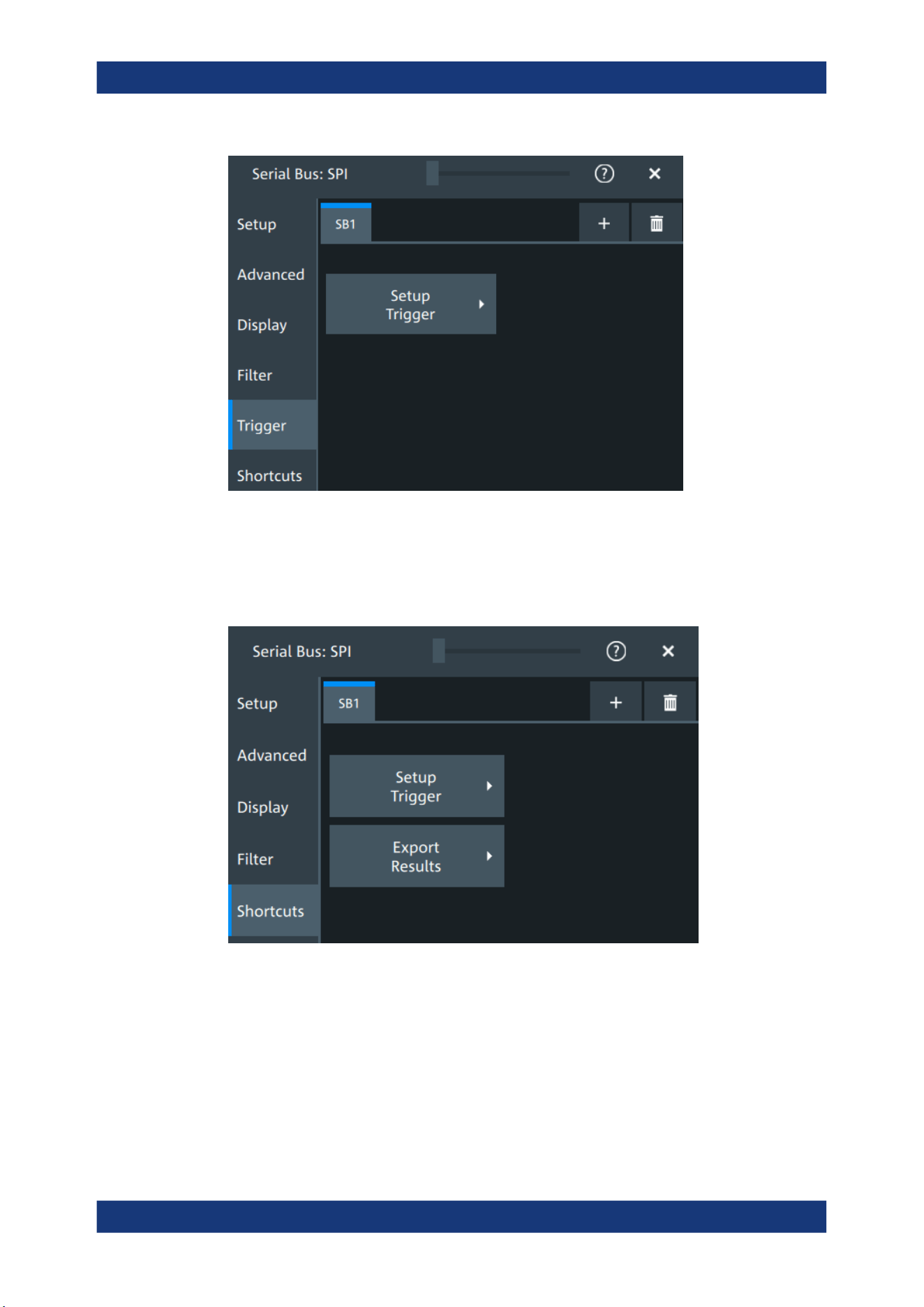
Protocol analysis
R&S
®
MXO 5 Series
290User Manual 1802.3369.02 ─ 02
13.1.6 Shortcuts
The "Shortcuts" tab gives quick access to other dialogs with protocol relevant settings.
The availability depends on the functions supported by the protocol.
If you access a dialog from the "Shortcuts" tab, some settings are already predefined.
●
"Setup trigger": you can trigger on various events that are typical for the selected
protocol type, for example, on start and stop of messages, or on specified data pat-
terns in the message.
●
"Export results": in this dialog, you can select the decode results you want to export
and the protocol-specific details to be included.
Basics of protocol analysis
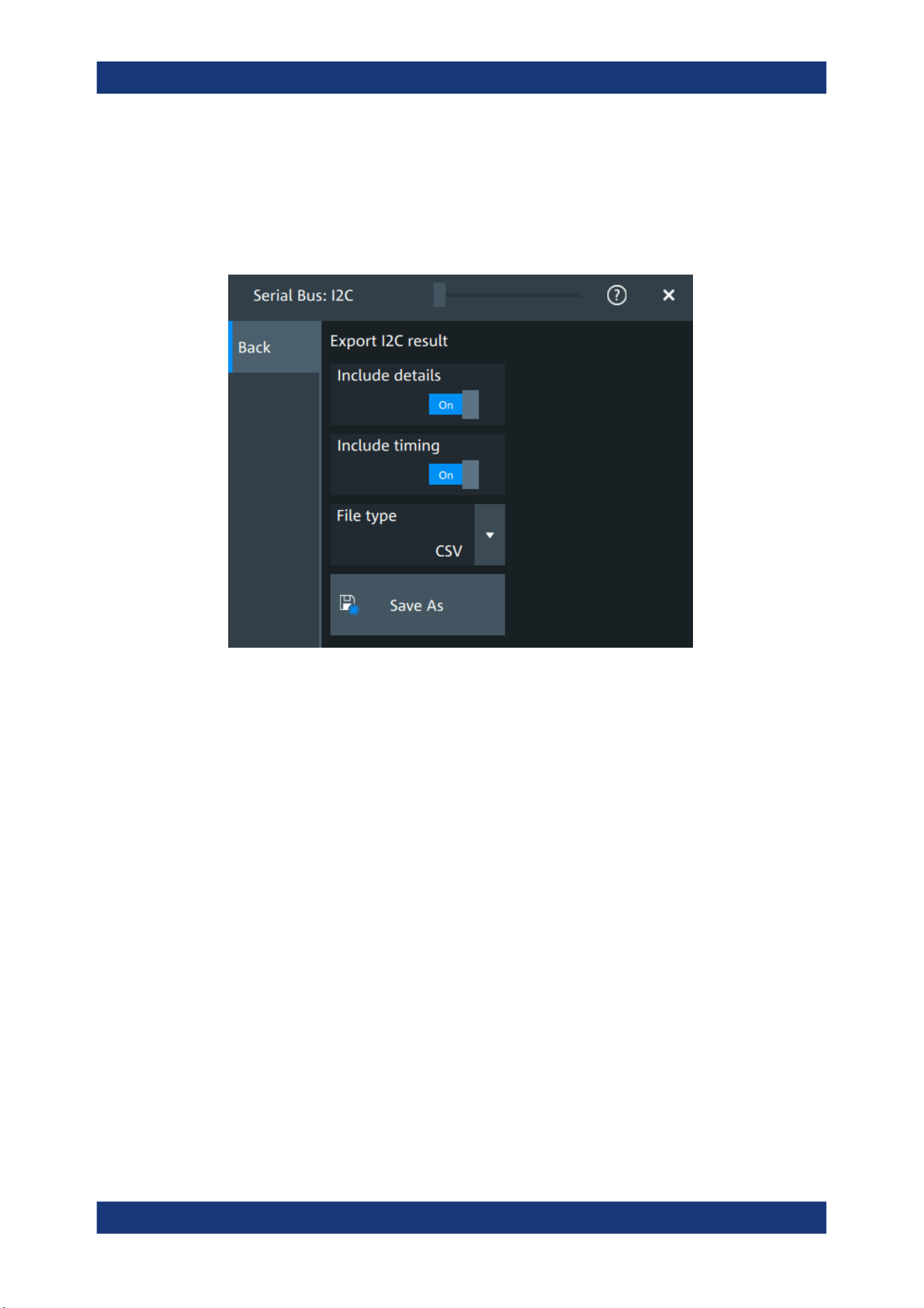
Protocol analysis
R&S
®
MXO 5 Series
291User Manual 1802.3369.02 ─ 02
13.1.7 Export protocol results
In the "Export results" dialog, you can export the results and all details of the selected
protocol.
The contents of the files are described in the
Include details
If enabled, includes the detailed results for all frames in the export result file.
Remote command:
SBUS<sb>:EXPResult:DETail on page 647
Include timing
If enabled, includes the frame timing in the export result file.
Remote command:
SBUS<sb>:EXPResult:TIME on page 647
File type
Selects the file format.
".csv"
The results are saved as a CSV compatible file.
".html"
The results are saved as webpage for display in a browser.
".xml"
The results are saved in an xml compatible file format.
".py"
The values are saved in a Python compatible file format.
Remote command:
SBUS<sb>:EXPResult:EXTension on page 648
Basics of protocol analysis
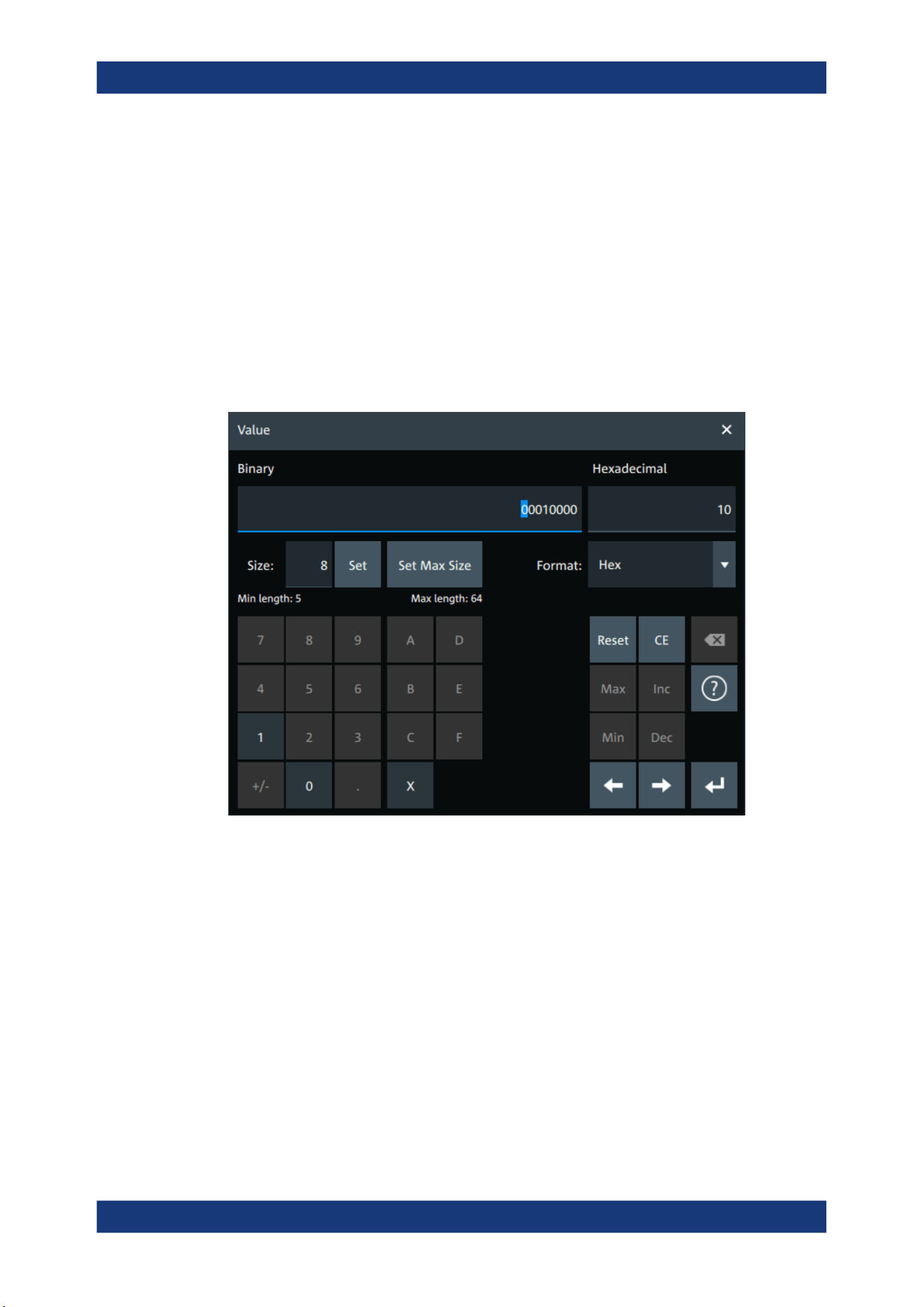
Protocol analysis
R&S
®
MXO 5 Series
292User Manual 1802.3369.02 ─ 02
Save as
Opens a dialog box where you can select a filename and a path for the export results
file.
Remote command:
SBUS<sb>:EXPResult:SAVE on page 647
SBUS<sb>:EXPResult:PATH on page 648
13.1.8 Bit pattern editor
If you want to enter a specified address or data pattern, the pattern editor helps you to
enter the pattern in various formats - decimal, hexadecimal, octal, binary and ASCII.
The editor at the top displays the pattern in two columns. The left column always
shows binary data. For the right column, you can select the "Format". The default
depends on the data specifics. You can edit data in the left or right column. The keypad
adapts itself to the column format and only keys appropriate to the format are enabled.
The data is grouped and converted in bit groups. The size of a bit group depends on
the address or data specifics and is set by the instrument. Groups are automatically
separated by blanks. The maximum size of a bit group is 64 bit, the most common
group size is 1 byte.
Format-specific information:
●
Binary: 0, 1 and X (do not care) is allowed.
●
Octal: Each digit represents 3 bit.
●
Hex: most common format in the right column.
Basics of protocol analysis

Protocol analysis
R&S
®
MXO 5 Series
293User Manual 1802.3369.02 ─ 02
●
ASCII: In the ASCII column, "X" is the character X. The binary X (do not care) is
not allowed. If an X is included in the binary value in the left column, the ASCII col-
umn displays "§" to indicate that the value is not defined.
●
Unsigned: Decimal data format without sign. 3 digits are grouped and next group is
separated by comma, e.g. 653,848.
●
Signed: Signed decimal format. 3 digits are grouped. The first bit represents the
sign. You can use the 2's complement format. 3 digits are grouped and next group
is separated by comma, e.g. -653,848.
13.2 SPI bus (option R&S MXO5-K510)
The Serial Peripheral Interface SPI is used for communication with slow peripheral
devices, in particular, for transmission of data streams.
Required options and equipment
For performing SPI decode measurements, you need the following equipment:
●
R&S MXO 5 with 4 channels. The channels can be a combination of the following:
– Analog channels (C1-C4)
– Logic channels (D0-D15) (requires option R&S MXO5-B1)
●
Option R&S MXO5-K510
13.2.1 About the SPI protocol
A 4-channel instrument is required for full support of the SPI protocol, or the MSO
option R&S MXO5-B1.
The Serial Peripheral Interface SPI is used for communication with slow peripheral
devices, in particular, for transmission of data streams.
Main characteristics of SPI are:
●
Main-subnode communication
●
No device addressing. The sub is accessed by a chip select, or sub select line.
●
No acknowledgment mechanism to confirm receipt of data
●
Duplex capability
Most SPI buses have four lines, two data and two control lines:
●
Clock line to all subs (SCLK)
●
Sub select or Chip select line (SS or CS)
●
Main data output, sub data input (MOSI or SDI)
●
Main data input, sub data output (MISO or SDO)
When the main generates a clock and selects a sub device, data may be transferred in
either or both directions simultaneously.
SPI bus (option R&S
MXO5-K510)

Protocol analysis
R&S
®
MXO 5 Series
294User Manual 1802.3369.02 ─ 02
1234567 0
CS
SCLK
MOSI
MISO
Shift Register
SPI Sub
1234567 0
CS
SCLK
MOSI
MISO
Shift Register
SPI Main
Figure 13-2: Simple configuration of SPI bus
The data bits of a message are grouped by following criteria:
●
A word contains several successive bits. The word length is defined in the protocol
configuration.
●
A frame contains several successive words, at least one word.
13.2.2 SPI configuration
13.2.2.1 SPI configuration settings
Access: [Apps] key > "Protocol" tab > "SPI" > "Setup".
Make sure that the tab of the correct serial bus is selected.
SPI bus (option R&S MXO5-K510)
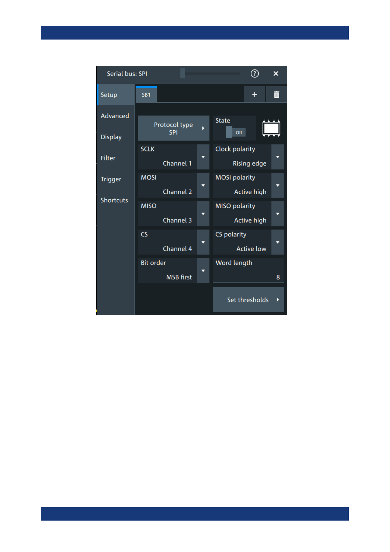
Protocol analysis
R&S
®
MXO 5 Series
295User Manual 1802.3369.02 ─ 02
Protocol type
Displays the protocol type to be decoded.
Remote command:
SBUS<sb>:TYPE on page 645
State
Enables the decoding of the selected bus. The signal icon of the bus appears on the
signal bar.
SCLK,MOSI,MISO,CS
Sets the input channel for the respective line:
●
SCLK: clock line
●
MOSI line
●
MISO line
●
CS: chip select
Alternatively, digital channels can be used if MSO option R&S MXO5-B1 is installed.
Digital and analog channels cannot be used at the same time.
SPI bus (option R&S
MXO5-K510)

Protocol analysis
R&S
®
MXO 5 Series
296User Manual 1802.3369.02 ─ 02
For triggering on a serial bus, analog or digital channel sources are required.
Remote command:
SBUS<sb>:SPI:MISO:SOURce on page 651
SBUS<sb>:SPI:MOSI:SOURce on page 652
SBUS<sb>:SPI:SCLK:SOURce on page 653
SBUS<sb>:SPI:CSELect:SOURce on page 650
Clock polarity
Two settings define the clock mode: the clock polarity and the clock phase. Together,
they determine the edges of the clock signal on which the data are driven and sam-
pled.
A master/slave pair must use the same parameter pair values to communicate. The
clock phase defines the slope. It selects if data is stored with the rising or falling slope
of the clock. The slope marks the begin of a new bit.
Polarity: MOSI, MISO, CS
Selects if the transmitted signal for the respective line is active high (high = 1) or active
low (low = 1).
For triggering on a serial bus, analog or digital channel sources are required.
Remote command:
SBUS<sb>:SPI:MISO:POLarity on page 651
SBUS<sb>:SPI:MOSI:POLarity on page 652
SBUS<sb>:SPI:CSELect:POLarity on page 650
Bit order
Selects the bit order, which determines if the data of the messages starts with MSB
(most significant bit) or LSB (least significant bit).
Remote command:
SBUS<sb>:SPI:BORDer on page 649
Word length
Sets the word length (or symbol size), which is the number of bits in a message. The
maximum word length is 32 bit.
Remote command:
SBUS<sb>:SPI:WSIZe on page 654
Threshold
Press "Set thresholds", to open the "Threshold setup" dialog.
Enter the value directly in the field of the threshold setup dialog.
Additional to the threshold, you can also set a hysteresis.
If the signal value on the line is higher than the threshold, the signal state is high. Oth-
erwise, the signal state is considered low if the signal value is below the threshold.
The interpretation of high and low is defined by the "Polarity: MOSI, MISO, CS"
on page 296.
SPI bus (option R&S
MXO5-K510)
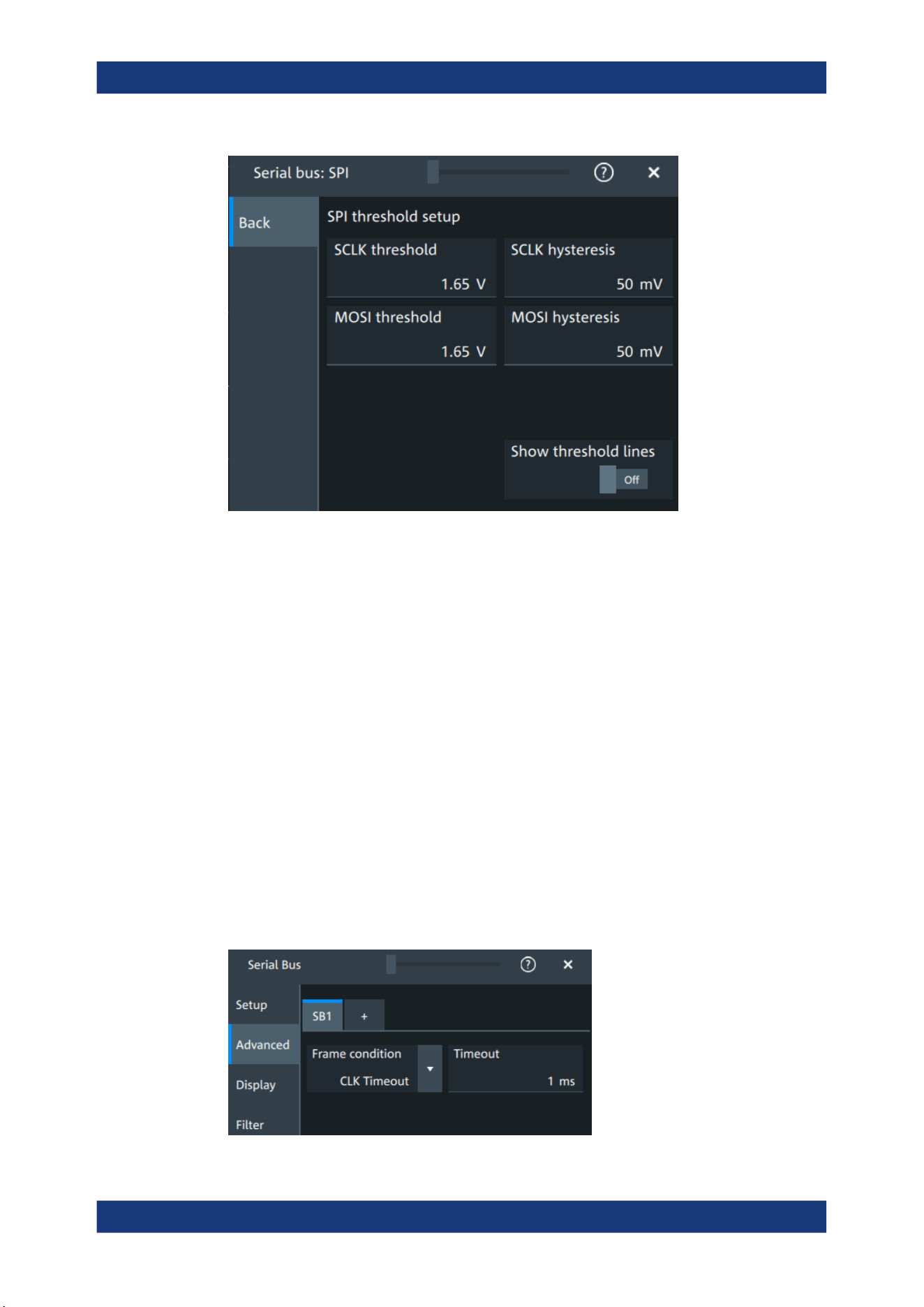
Protocol analysis
R&S
®
MXO 5 Series
297User Manual 1802.3369.02 ─ 02
Remote command:
SBUS<sb>:SPI:MISO:HYSTeresis on page 651
SBUS<sb>:SPI:MOSI:HYSTeresis on page 652
SBUS<sb>:SPI:SCLK:HYSTeresis on page 653
SBUS<sb>:SPI:CSELect:HYSTeresis on page 650
SBUS<sb>:SPI:MISO:THReshold on page 652
SBUS<sb>:SPI:MOSI:THReshold on page 653
SBUS<sb>:SPI:SCLK:THReshold on page 654
SBUS<sb>:SPI:CSELect:THReshold on page 650
Show threshold lines ← Threshold
If enabled, the threshold lines are displayed in the diagram.
The label of the threshold line is set according to the signal that it is referring to.
Remote command:
SBUS<m>:THReshold on page 646
13.2.2.2 Advanced
Access: [Apps] key > "Protocol" tab > "SPI" > "Advanced".
SPI bus (option R&S MXO5-K510)

Protocol analysis
R&S
®
MXO 5 Series
298User Manual 1802.3369.02 ─ 02
Frame condition
Defines the start of a frame. A frame contains a number of successive words, at least
one word.
"CS"
Start and end of the frame is defined by the active state of the sub
select signal.
"CLK timeout"
Defines a timeout on the clock line SCLK as limiter between two
frames. The timeout condition is used for SPI connections without a
CS line. Enter the minimum clock idle time in the field.
Remote command:
SBUS<sb>:SPI:FRCondition on page 649
Timeout
Sets the minimum clock idle time if a timeout on the clock line SCLK is used as limiter
between two frames.
See also: "Frame condition" on page 298.
Remote command:
SBUS<sb>:SPI:TIMeout on page 654
13.2.2.3 Display settings
For details about the display settings, see Chapter 13.1.3, "Display", on page 288.
13.2.2.4 Shortcuts
For details about the available shortcuts, see Chapter 13.1.6, "Shortcuts",
on page 290.
13.2.3 SPI filter
Access:[Apps] key > "Protocol" tab > "SPI" > "Filter" tab
SPI bus (option R&S MXO5-K510)
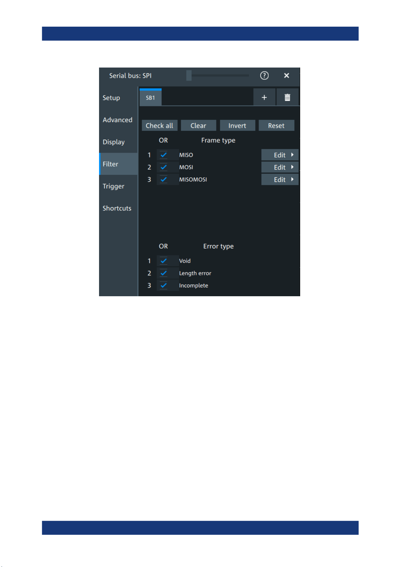
Protocol analysis
R&S
®
MXO 5 Series
299User Manual 1802.3369.02 ─ 02
In the "Filter" tab, you can define the settings to display only the frames that match the
selected filter conditions.
Check all, Clear, Invert, Reset
The following settings help you select the frames and errors you want to filter for. Only
the frames and error types that match the selected filter conditions are displayed.
"Check all"
Enables the filter for all available frames and error types.
"Clear"
Disables the filter for all available frames and error types.
"Invert"
Inverts the current state of the frame and error types: all frames and
error types that were enabled are disabled and vice versa.
"Reset"
Resets the state of the selected frames and error types.
Frame type
Selects the frame type that you want to display. You can filter all enabled frame types
simultaneously.
For each frame type, you can also specify conditions for the value of the fields in the
"Edit" dialog.
The available frames are "MOSI", "MISO" and "MOSI/MISO".
SPI bus (option R&S
MXO5-K510)
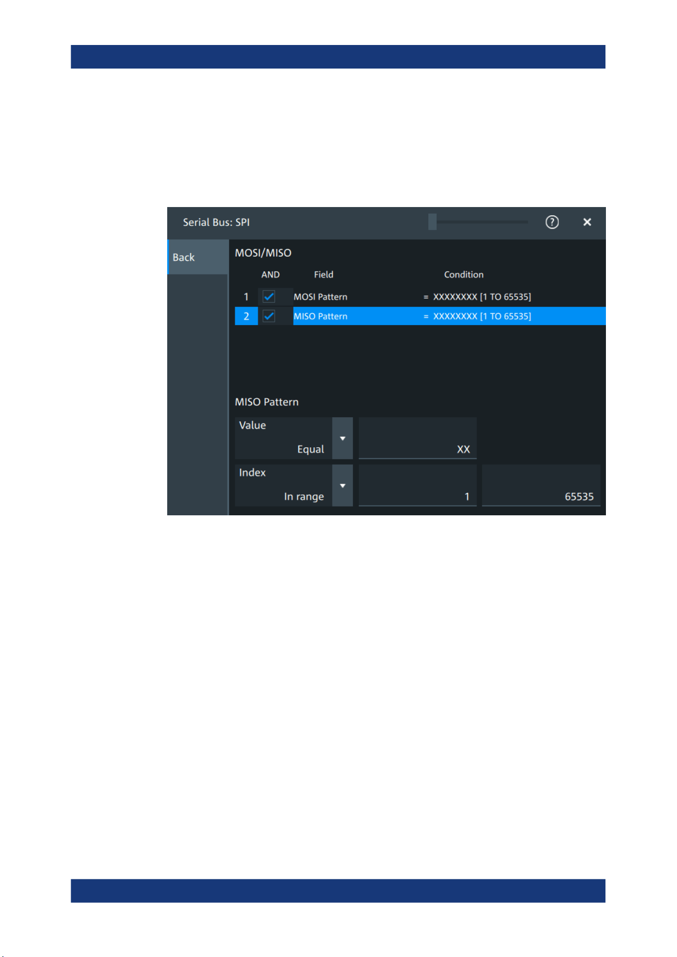
Protocol analysis
R&S
®
MXO 5 Series
300User Manual 1802.3369.02 ─ 02
Remote command:
SBUS<sb>:SPI:FILTer:FRAMe<fr>:ENABle on page 658
SBUS<sb>:SPI:FILTer:FRENable on page 658
Edit
Opens a dialog to define the details of the selected frame.
"Field"
Enables the field type that you want to filter on for the selected frame.
The available fields are "MOSI Pattern" and "MISO Pattern".
Remote command:
SBUS<sb>:SPI:FILTer:FIENable on page 658
SBUS<sb>:SPI:FILTer:FRAMe<fr>:FLD<fl>:ENABle
on page 658
"Condition"
Displays the value condition for the selected field.
Remote command:
SBUS<sb>:SPI:FILTer:FRAMe<fr>:FLD<fl>:BIT on page 656
SPI bus (option R&S MXO5-K510)

Protocol analysis
R&S
®
MXO 5 Series
301User Manual 1802.3369.02 ─ 02
"Data"
The data setup consists of a comparison condition and one or two
data patterns.
Remote command:
SBUS<sb>:SPI:FILTer:FRAMe<fr>:FLD<fl>:DMAX
on page 656
SBUS<sb>:SPI:FILTer:DMAX on page 656
SBUS<sb>:SPI:FILTer:FRAMe<fr>:FLD<fl>:DMIN
on page 657
SBUS<sb>:SPI:FILTer:DMIN on page 657
SBUS<sb>:SPI:FILTer:FRAMe<fr>:FLD<fl>:DOPerator
on page 657
SBUS<sb>:SPI:FILTer:DOPerator on page 657
"Index"
The index setup consists of a comparison condition and one or two
index values.
Remote command:
SBUS<sb>:SPI:FILTer:FRAMe<fr>:FLD<fl>:IMAX
on page 658
SBUS<sb>:SPI:FILTer:IMAX on page 658
SBUS<sb>:SPI:FILTer:FRAMe<fr>:FLD<fl>:IMIN
on page 659
SBUS<sb>:SPI:FILTer:IMIN on page 659
SBUS<sb>:SPI:FILTer:FRAMe<fr>:FLD<fl>:IOPerator
on page 659
SBUS<sb>:SPI:FILTer:IOPerator on page 659
Edit
Opens a dialog to define the details of the selected frame.
Error type
Enables filtering on the selected error type.
Available error types are "Void", "Length error" and "Incomplete".
Remote command:
SBUS<sb>:SPI:FILTer:ERRor<n>:ENABle on page 657
13.2.4 SPI trigger
Access: [Apps] key > "Protocol" tab > "SPI" > "Shortcuts".
SPI bus (option R&S MXO5-K510)

Protocol analysis
R&S
®
MXO 5 Series
302User Manual 1802.3369.02 ─ 02
Type
Selects the trigger type for SPI analysis.
Some trigger types have additional settings that can be defined. In this case, the "Set
details" button appears next to "Type" the function. Open it for a detailed definition of
the trigger conditions.
"Start of frame"
Sets the trigger to the beginning of the frame.
"End of frame"
Sets the trigger to the end of the frame.
"MOSI"
Sets the trigger to a specified data pattern expected on the MOSI
line.
Available, if there is a channel assigned to the "MOSI" line in the
"Setup" tab.
"MISO"
Sets the trigger to a specified data pattern expected on the MISO
line.
Available, if there is a channel assigned to the "MISO" line in the
"Setup" tab.
Remote command:
TRIGger:SPI:TYPE on page 660
Data conditions
The trigger on MOSI and MISO patterns is defined in the same way:
SPI bus (option R&S MXO5-K510)

Protocol analysis
R&S
®
MXO 5 Series
303User Manual 1802.3369.02 ─ 02
Search mode ← Data conditions
Defines how the specified data pattern is searched.
"Bit-aligned"
Bit-by-bit: the pattern can start at any position in the message.
"Word-aligned"
The pattern is matched only at word boundaries.
Remote command:
TRIGger:SPI:PALignment on page 661
Data ← Data conditions
Selects the operator condition for the data pattern and sets the data pattern.
Remote command:
TRIGger:SPI:FCONdition on page 661
TRIGger:SPI:DMINpattern on page 660
Position ← Data conditions
Sets the number of bits or words to be ignored before the first bit or word of interest.
Remote command:
TRIGger:SPI:DPOSition on page 660
13.2.5 SPI decode results
When the configuration of the serial bus is complete, the signal can be decoded:
1. Open the "Serial Bus" dialog for the respective bus.
2. In the "Setup" tab, enable "State".
3. In the "Display" tab, enable "Show decode table".
For a description of the display settings, see also Chapter 13.1.3, "Display",
on page 288.
The instrument captures and decodes the signal according to the standard definition
and the configuration settings.
The color-coding of the various protocol sections and errors simplifies the interpretation
of the visual display. The decode information condenses or expands, depending on the
horizontal scale. Various data formats are available to show the result values.
Decode results table
The "Decode results" table contains information about all decoded frames.
SPI bus (option R&S
MXO5-K510)
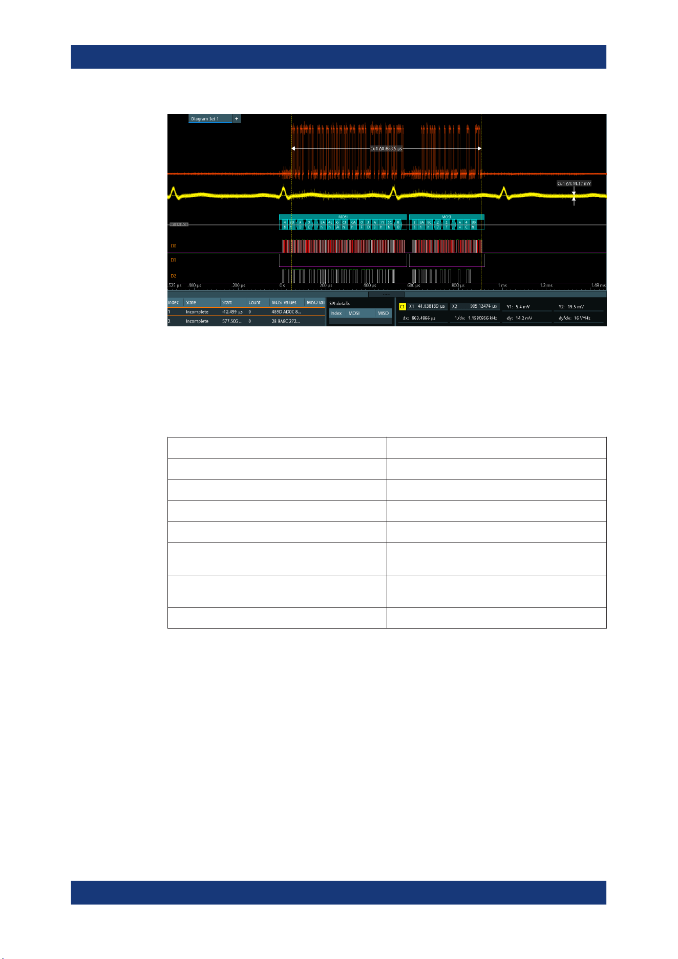
Protocol analysis
R&S
®
MXO 5 Series
304User Manual 1802.3369.02 ─ 02
Figure 13-3: Decoded and binary SPI signal
Green brackets [...] = Start and end of complete frame
Red brackets [...] = Start and end of incomplete frame
Yellow = Word
Red = Error
Table 13-1: Content of the "Decode results" table
Column Description
Index Index of the decoded frame
State Overall state of the frame
Start Times of frame start
Count Number of words in the frame
MOSI values Value of the MOSI data words. The data format is
selected in the "Display" tab.
MISO values Value of the MISO data words. The data format is
selected in the "Display" tab.
Bit rate Value of the bit rate
Data format
You can select various data formats for the values displayed in the decode table and in
the combs of the decoded signal.
Remote command:
●
SBUS<sb>:FORMat on page 645
Export of decode results
1. In the protocol "Shortcuts" tab, press "Export results".
The "Export results" dialog opens.
For details, see Chapter 13.1.7, "Export protocol results", on page 291.
SPI bus (option R&S
MXO5-K510)
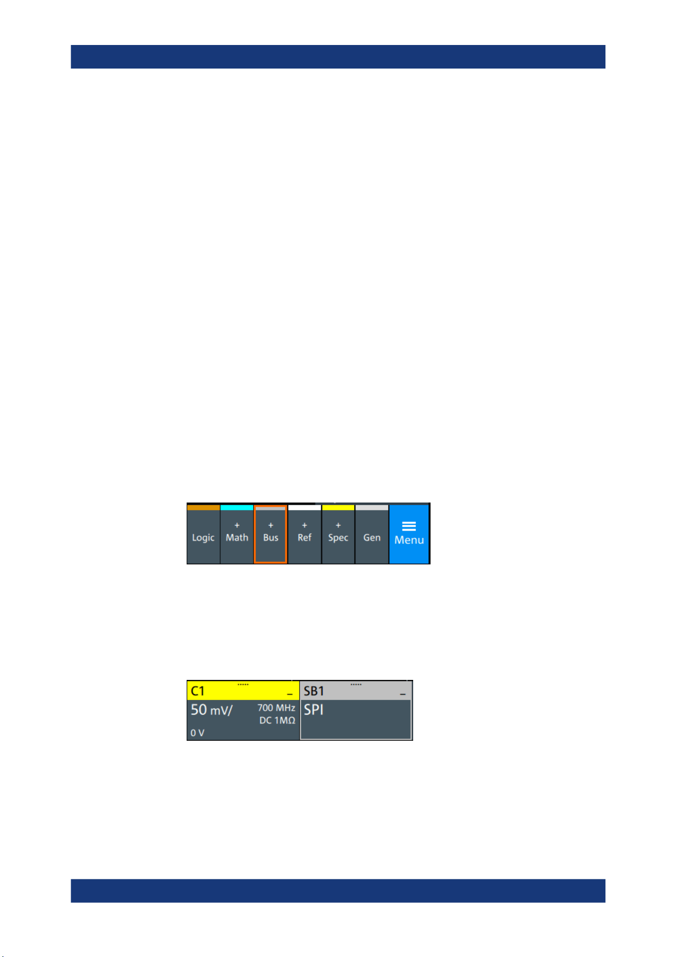
Protocol analysis
R&S
®
MXO 5 Series
305User Manual 1802.3369.02 ─ 02
2. Select the details that you want to export and the file format.
3. Tap "Save as".
4. Key in a name and select the file format.
Remote commands
Remote commands to retrieve decode results are described in Chapter 17.16.2.4,
"Decode results", on page 661.
13.2.6 Performing SPI decoding
This chapter explains step by step how to configure and decode the SPI bus.
For more information on decoding SPI, you can also refer to the video, available on the
Rohde & Schwarz YouTube channel: Decoding SPI with MXO Series Oscilloscope.
13.2.6.1 Configuring SPI signals
For configuration, assign the lines to the input channels, and define the active states
and the logical thresholds.
For details on configuration settings, see Chapter 13.2.2, "SPI configuration",
on page 294.
1. Tap the "Bus" activator in the bottom right of the screen.
2. Select the tab of the bus that you want to set up, for example "SB1".
3. Tap the "Protocol type" button. Select the protocol: "SPI".
4. Tap on "State" to enable the decoding.
An SPI shortcut appears at the bottom left of the screen. Tap on the shortcut for a
quick access to the "SPI" dialog settings.
5. Tap on each active wire and select the correct channels: "SCLK", "MOSI", "MISO",
"CS".
6. Set "Bit order" to "MSB" or "LSB first".
7. Set "Clock polarity" to "Rising edge" (CPOL = 0) or "Falling edge" (CPOL = 1).
SPI bus (option R&S
MXO5-K510)
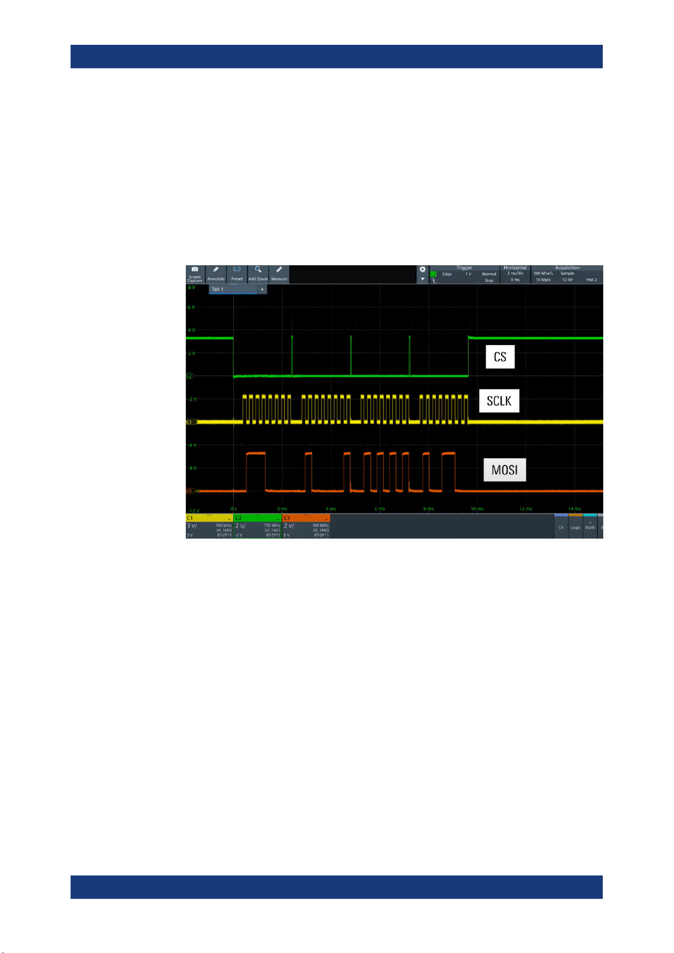
Protocol analysis
R&S
®
MXO 5 Series
306User Manual 1802.3369.02 ─ 02
8. Set "MOSI polarity"/"MISO polarity" to "Active high"(CPHA = 0) or "Active
low"(CPHA = 1).
9. Set "CS polarity" to "Active high" or "Active low".
The typical value is "Active low", which means that the line is pulled low on mes-
sage start.
10. Set the "Word length". The typical value is 8.
11. Check that the signals are on the screen.
If not try adjusting the vertical and horizontal settings.
12. Set the logical thresholds:
a) Tap "Threshold setup". The threshold dialog opens.
b) For each wire, set the threshold value. A typical value is 1.65 V.
c) If necessary, set the hysteresis value for the wires.
d) Optionally, tap on "Show threshold lines".
SPI bus (option R&S MXO5-K510)
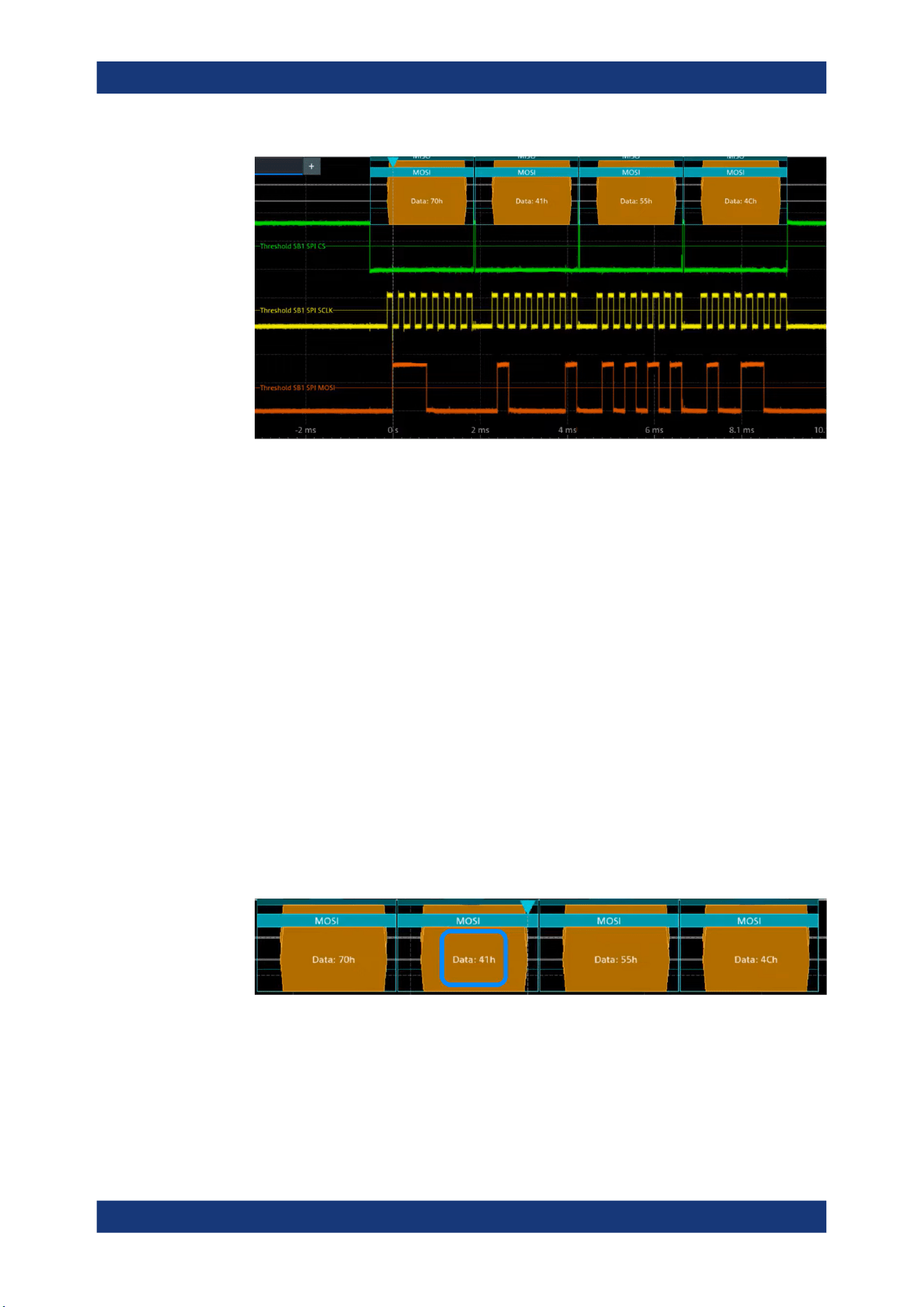
Protocol analysis
R&S
®
MXO 5 Series
307User Manual 1802.3369.02 ─ 02
13.2.6.2 Triggering on SPI
Prerequisites: A bus is configured for the SPI signal to be analyzed. See Chap-
ter 13.2.6.1, "Configuring SPI signals", on page 305.
For details on configuration settings, see Chapter 13.2.2, "SPI configuration",
on page 294.
1. Open "Menu" > "Trigger".
2. Set "Trigger on" to "Single event".
3. Ensure that the "Source" is set to the configured serial bus, e.g. "Serial bus 1".
4. Select the "Type".
5. Define additional settings for more complex trigger types ("MOSI"/ "MISO"):
a) Tap on "Set details".
b) Set the "Search mode".
c) Set the "Data pattern" or a data range.
In the following example a decode for triggering on "MOSI" triggered on "Data pat-
tern" = 0x41.
Figure 13-4: Trigger on Type= MOSI, Data pattern = 41
13.2.6.3 Exporting decode results
Once a decode has been completed, you can export the decode results of the
SPI bus (option R&S
MXO5-K510)

Protocol analysis
R&S
®
MXO 5 Series
308User Manual 1802.3369.02 ─ 02
Prerequisites: A bus is configured for the SPI and decoded.
1. Tap on the "SPI" shortcut.
2. Tap on the "Shortcuts" tab.
3. Tap "Export results".
4. If necessary, enable "Include details".
5. If necessary, enable "Include timing".
6. Select the "File type".
An export file is saved in the selected directory.
The SPI export file contains the following fields:
●
A list of all decoded frames:
– Index
– Start
– Stop
– Source
– State
– Bit rate
●
The details frame includes the following fields:
– Index
– Start time
– Stop time
– MOSI values
– MISO values
Example SPI export file
Index,Start,Stop,State,Count,BitRate
1,-2.9e-05,-2.872e-05,'OK',2,50000000
2,-2.844e-05,-2.83e-05,'OK',1,50000000
3,-2.816e-05,-2.788e-05,'OK',2,50000000
4,-2.76e-05,-2.746e-05,'VOID',0,---
Details frame 1
Index,Start Time,Stop Time,MOSI Values,MISO Values
1,-2.9e-05,-2.886e-05,AFh,---
2,-2.886e-05,-2.872e-05,FEh,---
Details frame 2
Index,Start Time,Stop Time,MOSI Values,MISO Values
1,-2.844e-05,-2.83e-05,---,34h
Details frame 3
Index,Start Time,Stop Time,MOSI Values,MISO Values
SPI bus (option R&S
MXO5-K510)

Protocol analysis
R&S
®
MXO 5 Series
309User Manual 1802.3369.02 ─ 02
1,-2.816e-05,-2.802e-05,CAh,F0h
2,-2.802e-05,-2.788e-05,05h,0Dh
13.3 I²C (option R&S MXO5-K510)
The Inter-Integrated Circuit is a simple, low-bandwidth, low-speed protocol used for
communication between on-board devices, for example, in LCD and LED drivers,
RAM, EEPROM, and others.
Required options and equipment
For performing I²C decode measurements, you need the following equipment:
●
R&S MXO 5 with 2 available channels. The channels can be a combination of the
following:
– Analog channels (C1-C4)
– Logic channels (D0-D15) (requires option R&S MXO5-B1)
●
Option R&S MXO5-K510
● About the I²C protocol........................................................................................... 309
● I²C configuration....................................................................................................311
● I2C filter.................................................................................................................314
● I²C trigger settings.................................................................................................316
● I²C decode results.................................................................................................320
● Performing I2C decoding...................................................................................... 322
13.3.1 About the I²C protocol
This chapter provides an overview of protocol characteristics, data format, address
types and trigger possibilities. For detailed information, read the "I2C-bus specification
and user manual" available on the NXP manuals webpage at http://www.nxp.com/.
I²C characteristics
Main characteristics of I²C are:
●
Two-wire design: serial clock (SCL) and serial data (SDA) lines
●
Controller/ target communication: the controller generates the clock and addresses
the targets. Targets receive the address and the clock. Both controller and targets
can transmit and receive data.
●
Addressing scheme: each target device is addressable by a unique address. Multi-
ple target devices can be linked together and can be addressed by the same con-
troller.
●
Read/write bit: specifies if the controller reads (=1) or writes (=0) the data.
●
Acknowledge: takes place after every byte. The receiver of the address or data
sends the acknowledge bit to the transmitter.
I²C (option R&S
MXO5-K510)
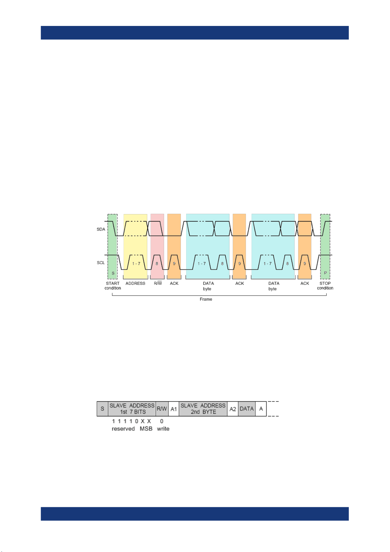
Protocol analysis
R&S
®
MXO 5 Series
310User Manual 1802.3369.02 ─ 02
The R&S MXO 5 supports all operating speed modes: high-speed, fast mode plus, fast
mode, and standard mode.
Data transfer
The format of a simple I²C message (frame) with 7-bit addressing consists of the fol-
lowing parts:
●
Start condition: a falling slope on SDA while SCL is high
●
7-bit address of the target device that either is written to or read from
●
R/W bit: specifies if the data is written to or read from the target
●
ACKnowledge bits: is issued by the receiver of the previous byte if the transfer was
successful
Exception: At read access, the controller terminates the data transmission with a
NACK bit after the last byte.
●
Data: several data bytes with an ACK bit after every byte
●
Stop condition: a rising slope on SDA while SCL is high
Figure 13-5: I2C writes access with 7-bit address
Address types: 7-bit and 10-bit
Target addresses can be 7 bits or 10 bits long. A 7-bit address requires 1 byte, 7 bits
for the address followed by the R/W bit.
A 10-bit address for write access requires 2 bytes: the first byte starts with the reserved
sequence 11110, followed by the two MSB of the address and the write bit. The second
byte contains the remaining 8 LSB of the address. The target acknowledges each
address byte.
Figure 13-6: 10-bit address, write access
A 10-bit address for read access requires 3 bytes. The first 2 bytes are identical to the
write access address. The third byte repeats the address bits of the first byte and sets
the read bit.
I²C (option R&S
MXO5-K510)
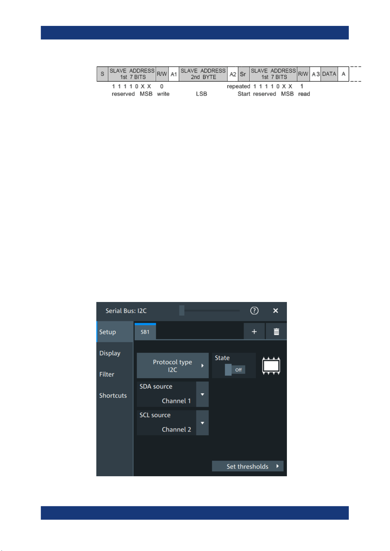
Protocol analysis
R&S
®
MXO 5 Series
311User Manual 1802.3369.02 ─ 02
Figure 13-7: 10-bit address, read access
Trigger
The R&S MXO 5 can trigger on various parts of I²C messages. The data and clock
lines must be connected to the input channels, triggering on math and reference wave-
forms is not possible.
You can trigger on:
●
Start or stop condition
●
Repeated start condition
●
Transfer direction (read or write)
●
Bytes with missing acknowledge bit
●
Specific data pattern in the message
13.3.2 I²C configuration
13.3.2.1 I²C configuration settings
Access: [Apps] key > "Protocol" tab > "I2C" > "Setup".
I²C (option R&S MXO5-K510)
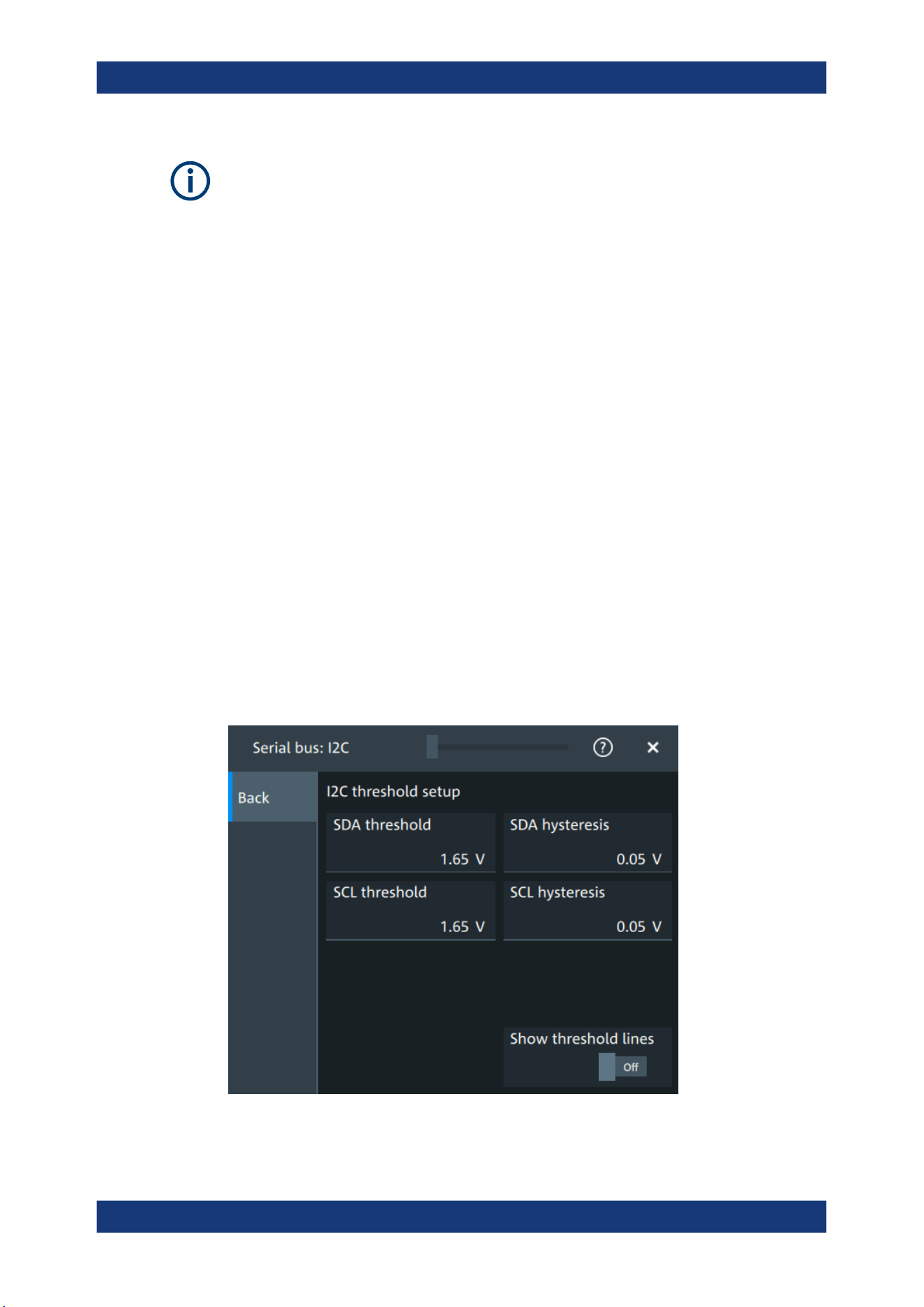
Protocol analysis
R&S
®
MXO 5 Series
312User Manual 1802.3369.02 ─ 02
Make sure that the tab of the correct serial bus is selected.
Protocol type
Displays the protocol type to be decoded.
Remote command:
SBUS<sb>:TYPE on page 645
State
Enables the decoding of the selected bus. The signal icon of the bus appears on the
signal bar.
SDA source
Sets the source channel to which the data line is connected.
Remote command:
SBUS<sb>:I2C:SDA:SOURce on page 668
SCL source
Selects the source channel to which the clock line is connected.
Remote command:
SBUS<sb>:I2C:SCL:SOURce on page 667
Threshold
Press "Set thresholds", to open the "Threshold setup" dialog.
Enter the value directly in the field of the threshold setup dialog.
Additional to the threshold, you can also set a hysteresis.
I²C (option R&S MXO5-K510)

Protocol analysis
R&S
®
MXO 5 Series
313User Manual 1802.3369.02 ─ 02
Remote command:
SBUS<sb>:I2C:SCL:THReshold on page 667
SBUS<sb>:I2C:SDA:THReshold on page 668
SBUS<sb>:I2C:SCL:HYSTeresis on page 667
SBUS<sb>:I2C:SDA:HYSTeresis on page 668
Show threshold lines ← Threshold
If enabled, the threshold lines are displayed in the diagram.
The label of the threshold line is set according to the signal that it is referring to.
Remote command:
SBUS<m>:THReshold on page 646
13.3.2.2 Display settings
For details about the display settings, see Chapter 13.1.3, "Display", on page 288.
Show symbols
Symbol lists are protocol-specific. Label lists for I2C are available in CSV format.
Remote command:
SBUS<sb>:I2C:SYMBols on page 669
SBUS<sb>:I2C:NEWList on page 669
13.3.2.3 I2C symbols
For the I2C protocol, you can upload symbol lists containing IDs and a symbolic name
for each node. You can load a file in one of the supported formats:
Label lists are protocol-specific. Label lists for I
2
C are available in CSV format.
An I
2
C label file contains three values for each address:
●
Address type, 7-bit or 10-bit long
●
Address value
●
Symbolic label: name of the address, specifying its function in the bus network.
Example: I
2
C CSV file
# ----------------------------------------------------------------------------
@FILE_VERSION = 1.00
@PROTOCOL_NAME = i2c
# ---------------------------------------------------------------------------
# Labels for I2C protocol
# Column order: Identifier type, Identifier value, Label
# ---------------------------------------------------------------------------
7,0x1E,Voltage
7,38h,Pressure
7,2Ah,Temperature
7,16h,Speed
7,118,Acceleration
7,07h,HighSpeed_Master_0x3
I²C (option R&S
MXO5-K510)
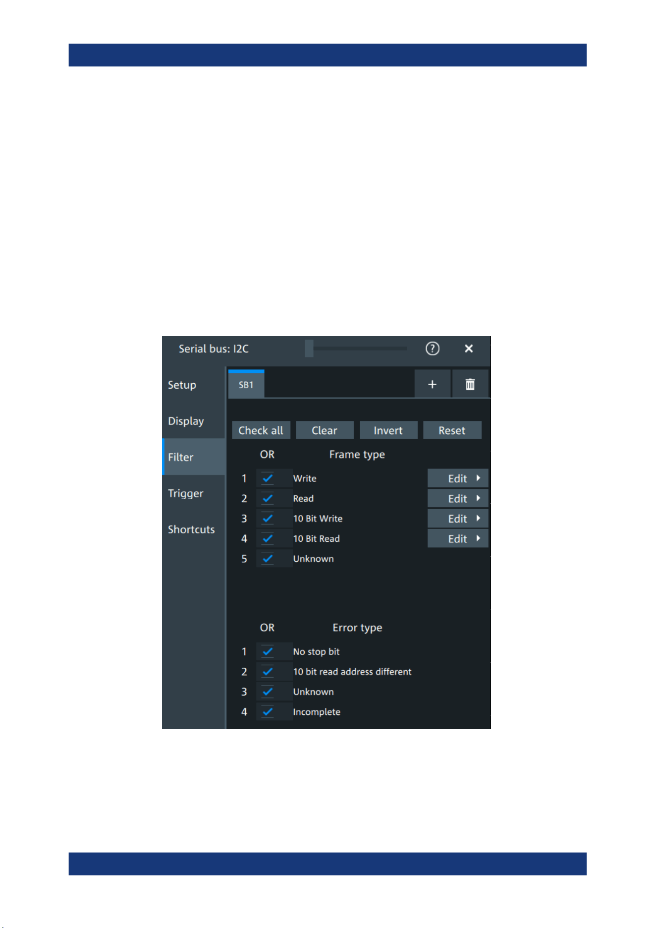
Protocol analysis
R&S
®
MXO 5 Series
314User Manual 1802.3369.02 ─ 02
7,51h,EEPROM
10,3A2h,DeviceSetup
10,1A3h,GatewayStatus
10,06Eh,LeftSensor
# ----------------------------------------------------------------------------
13.3.2.4 Shortcuts
For details about the available shortcuts, see Chapter 13.1.6, "Shortcuts",
on page 290.
13.3.3 I2C filter
Access: [Apps] key > "Protocol" tab > "I2C" > "Filter" tab
In the "Filter" tab, you can define the settings to display only the frames that match the
selected filter conditions.
I²C (option R&S
MXO5-K510)
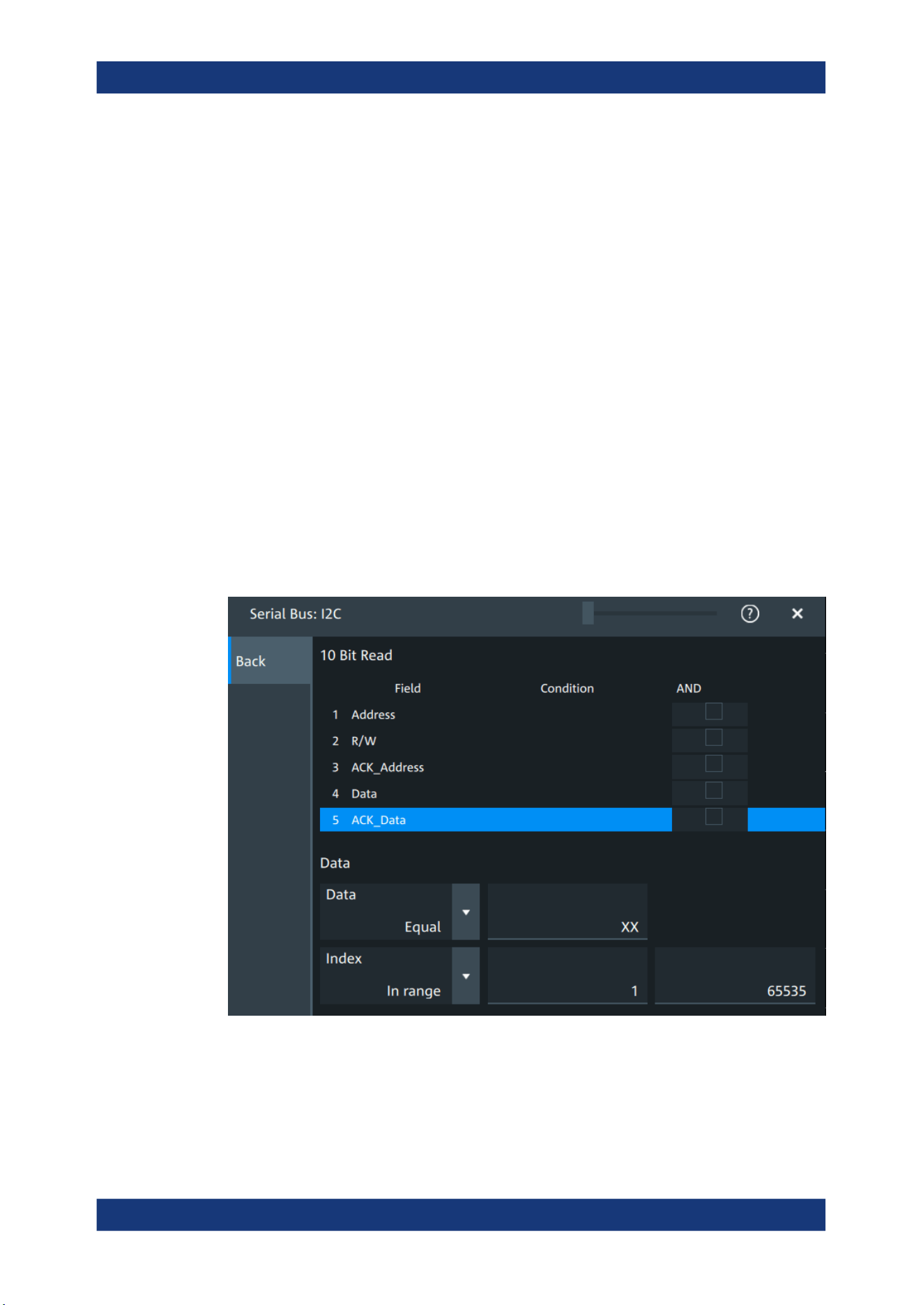
Protocol analysis
R&S
®
MXO 5 Series
315User Manual 1802.3369.02 ─ 02
Check all, Clear, Invert, Reset
The following settings help you select the frames and errors you want to filter for. Only
the frames and error types that match the selected filter conditions are displayed.
"Check all"
Enables the filter for all available frames and error types.
"Clear"
Disables the filter for all available frames and error types.
"Invert"
Inverts the current state of the frame and error types: all frames and
error types that were enabled are disabled and vice versa.
"Reset"
Resets the state of the selected frames and error types.
Frame type
Selects the frame type that you want to display. You can filter all enabled frame types
simultaneously.
For each frame type, you can also specify conditions for the value of the fields in the
"Edit" dialog.
Remote command:
SBUS<sb>:I2C:FILTer:FRENable on page 674
SBUS<sb>:I2C:FILTer:FRAMe<fr>:ENABle on page 674
Edit
Opens a dialog to define the details of the selected frame.
I²C (option R&S MXO5-K510)

Protocol analysis
R&S
®
MXO 5 Series
316User Manual 1802.3369.02 ─ 02
"Field"
Enables the field type that you want to filter on for the selected frame.
The available fields are "Address", "R/W", "ACK_A", "Data", and
"ACK_D".
Remote command:
SBUS<sb>:I2C:FILTer:FRAMe<fr>:FLD<fl>:ENABle
on page 677
SBUS<sb>:I2C:FILTer:FIENable on page 677
"Condition"
Displays the value condition for the selected field.
Remote command:
SBUS<sb>:I2C:FILTer:FRAMe<fr>:FLD<fl>:BIT on page 677
"Data"
The data setup consists of a comparison condition and one or two
data patterns.
Remote command:
SBUS<sb>:I2C:FILTer:FRAMe<fr>:FLD<fl>:DMAX
on page 674
SBUS<sb>:I2C:FILTer:DMAX on page 674
SBUS<sb>:I2C:FILTer:FRAMe<fr>:FLD<fl>:DMIN
on page 675
SBUS<sb>:I2C:FILTer:DMIN on page 675
SBUS<sb>:I2C:FILTer:FRAMe<fr>:FLD<fl>:DOPerator
on page 675
SBUS<sb>:I2C:FILTer:DOPerator on page 675
"Index"
The index setup consists of a comparison condition and one or two
index values.
Remote command:
SBUS<sb>:I2C:FILTer:FRAMe<fr>:FLD<fl>:IMAX
on page 676
SBUS<sb>:I2C:FILTer:IMAX on page 676
SBUS<sb>:I2C:FILTer:FRAMe<fr>:FLD<fl>:IMIN
on page 676
SBUS<sb>:I2C:FILTer:IMIN on page 676
SBUS<sb>:I2C:FILTer:FRAMe<fr>:FLD<fl>:IOPerator
on page 676
SBUS<sb>:I2C:FILTer:IOPerator on page 676
Error type
Enables filtering on the selected error type.
Remote command:
SBUS<sb>:I2C:FILTer:ERENable on page 675
SBUS<sb>:I2C:FILTer:ERRor<n>:ENABle on page 675
13.3.4 I²C trigger settings
Access: [Apps] > "Protocol" > "I²C" > "Shortcuts" > "Setup trigger"
I²C (option R&S
MXO5-K510)
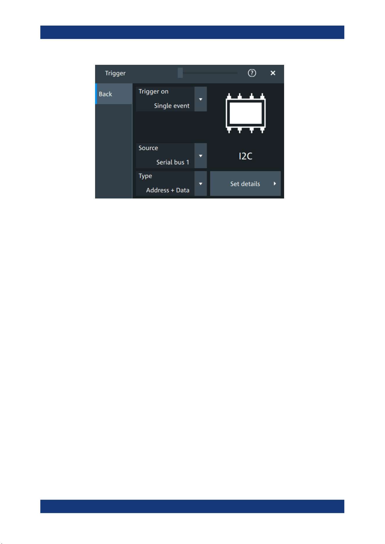
Protocol analysis
R&S
®
MXO 5 Series
317User Manual 1802.3369.02 ─ 02
Type
Selects the trigger type for I²C analysis.
Some trigger types have additional settings that can be defined. In this case, the "Set
details" button appears next to "Type" the function. Open it for a detailed definition of
the trigger conditions.
Remote command:
TRIGger:I2C:TYPE on page 670
Start ← Type
Sets the trigger to the start of the message. The start condition is a falling edge on
SDA while SCL is high. The trigger instant is the falling edge of the SDA line.
You can change the SDA and SCL lines here if necessary.
Repeated start ← Type
Sets the trigger to a repeated start - when the start condition occurs without previous
stop condition. Repeated start conditions occur when a controller exchanges multiple
messages with a target device without releasing the bus.
Stop ← Type
Sets the trigger to the end of the message. The stop condition is a rising slope on SDA
while SCL is high.
No Ack ← Type
Missing acknowledge bit: the instrument triggers if the data line remains HIGH during
the clock pulse following a transmitted byte.
I²C (option R&S
MXO5-K510)
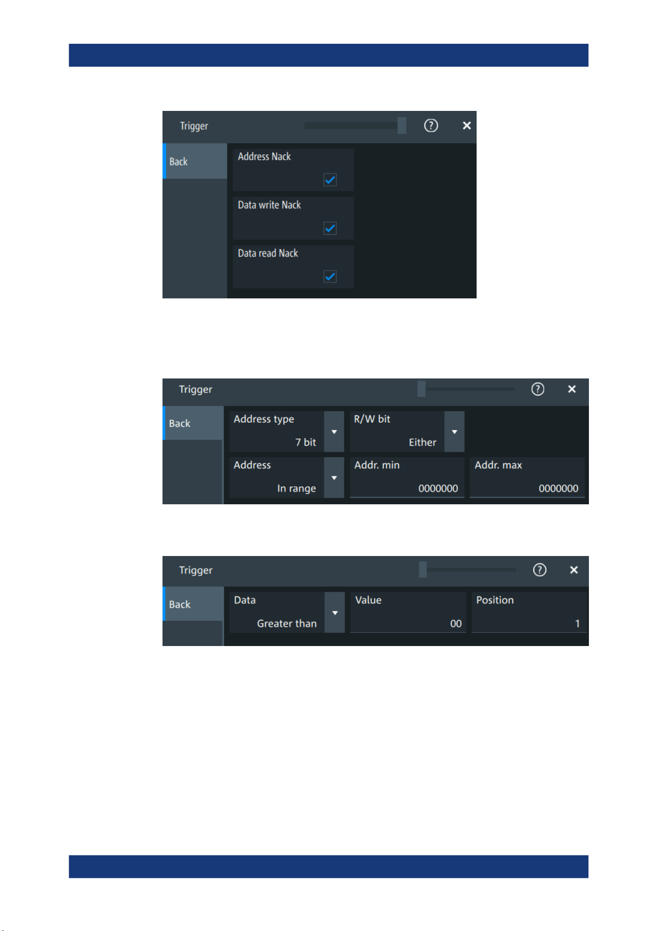
Protocol analysis
R&S
®
MXO 5 Series
318User Manual 1802.3369.02 ─ 02
Address ← Type
Sets the trigger to one specific address condition or a combination of address condi-
tions. The trigger time is the falling clock edge of the acknowledge bit after the
address.
Data ← Type
Sets the trigger to one specific data condition or a combination of address conditions.
Address and data ← Type
Sets the trigger to a combination of address and data condition.
I²C (option R&S
MXO5-K510)

Protocol analysis
R&S
®
MXO 5 Series
319User Manual 1802.3369.02 ─ 02
No Ack conditions
Selects which missing acknowledge bits is detected if the trigger type is set to "No
Ack".
"Address Nack"
No secondary recognizes the address.
"Data write Nack"
The addressed secondary does not accept the data.
"Data read Nack"
Marks the end of the read process when the primary reads data from
the secondary. This Nack is sent according to the protocol definition,
it is not an error.
Remote command:
TRIGger:I2C:ADNack on page 671
TRIGger:I2C:DWNack on page 673
TRIGger:I2C:DRNack on page 672
Address type
Sets the address length to be triggered on: 7 bit or 10 bit.
Remote command:
TRIGger:I2C:AMODe on page 672
R/W bit
Toggles the trigger condition between read and write access of the primary. Select
"Either" if the transfer direction is not relevant for the trigger condition.
Remote command:
TRIGger:I2C:ACCess on page 670
Address
The trigger address setup consists of a comparison condition and one or two address
patterns.
Defines the bit pattern of the secondary device address. The length of the entry is
adjusted to the selected address type.
"Condition"
Sets the comparison condition to a specific value or a range.
I²C (option R&S MXO5-K510)

Protocol analysis
R&S
®
MXO 5 Series
320User Manual 1802.3369.02 ─ 02
"From"
Specifies the value or sets the start value of a range.
"To"
Sets the maximum value of a range for "Condition" = "In range"/"Out
of range".
Remote command:
TRIGger:I2C:ADDRess on page 671
TRIGger:I2C:ADDTo on page 671
Data
Specifies the trigger conditions for the data bit pattern.
"Condition"
Sets the comparison condition to a specific value or a range.
"Value"
Specifies the value or sets the start value of a range.
Enter the bytes in msb first bit order. The maximum pattern length is
64 bit. Waveform data is compared with the pattern byte-by-byte.
Remote command:
TRIGger:I2C:DCONdition on page 672
TRIGger:I2C:DMIN on page 672
Position
Sets the number of data bytes to be skipped after the address.
Remote command:
TRIGger:I2C:DPOSition on page 672
13.3.5 I²C decode results
When the configuration of the serial bus is complete, the signal can be decoded:
1. Open the "Serial Bus" dialog for the respective bus.
2. In the "Setup" tab, enable "State".
3. In the "Display" tab, enable "Show decode table".
For a description of the display settings, see also Chapter 13.1.3, "Display",
on page 288.
The instrument captures and decodes the signal according to the standard definition
and the configuration settings.
The color-coding of the various protocol sections and errors simplifies the interpretation
of the visual display. The decode information condenses or expands, depending on the
horizontal scale. Various data formats are available to show the result values.
I²C (option R&S
MXO5-K510)
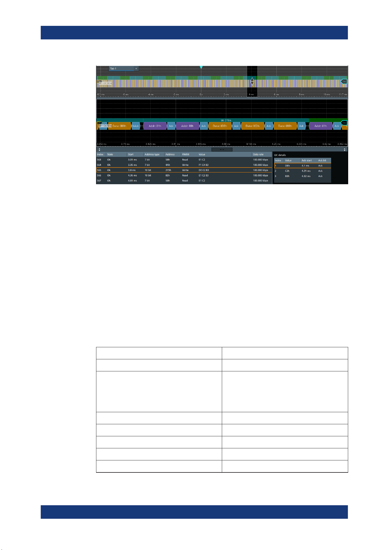
Protocol analysis
R&S
®
MXO 5 Series
321User Manual 1802.3369.02 ─ 02
Figure 13-8: Decoded I2C signal, and decode results
Purple = Address byte
Blue = R/W bit
Cyan = ACK bit
Red = NACK bit
Gold = Data byte
Turquoise = Write frame
Green = Read frame
Crimson red = Incomplete frame
The results are shown in two tables:
●
"Decode results": contains information about all decoded frames
●
"Details frame": contains more detailed information about the selected frame in the
"Decode results" table.
Decode results table
The "Decode results" table contains information about all decoded frames.
Table 13-2: Content of the Decode results table
Column Description
Index Index of the decoded frame
State Overall state of the frame.
"Insuffcient waveform length" indicates that the
frame is not completely contained in the acquisition.
Change the horizontal scale, or move the reference
point to the left to get a longer acquisition.
Start Time of frame start
Address type Address length, 7 bit or 10 bit
Address value (hex) Hexadecimal value of the address
R/W bit Value of the R/W bit
Data rate Value of the data rate
I²C (option R&S MXO5-K510)

Protocol analysis
R&S
®
MXO 5 Series
322User Manual 1802.3369.02 ─ 02
Table 13-3: Content of the Details results table
Column Description
Index Index of the decoded field
Value Value of all data bytes of the frame
ACK bit start Start time of the acknowledge bit
ACK bit Value of the address acknowledge bit
Data format
You can select various data formats for the values displayed in the decode table and in
the combs of the decoded signal.
Remote command:
●
SBUS<sb>:FORMat on page 645
Export of decode results
1. In the protocol "Shortcuts" tab, press "Export results".
The "Export results" dialog opens.
For details, see Chapter 13.1.7, "Export protocol results", on page 291.
2. Select the details that you want to export and the file format.
3. Tap "Save as".
4. Key in a name and select the file format.
Remote commands
Remote commands to retrieve decode results are described in Chapter 17.16.3.4,
"Decode results", on page 677.
13.3.6 Performing I2C decoding
This chapter explains step by step how to configure and decode the I2C bus.
For more information on decoding I2C, you can also refer to the video, available on the
Rohde & Schwarz YouTube channel: Decoding I2C with MXO Series Oscilloscope.
13.3.6.1 Configuring I2C signals
For configuration, assign the lines to the input channels, and define the active states
and the logical thresholds.
For details on configuration settings, see Chapter 13.3.2, "I²C configuration",
on page 311.
1. Tap the "Bus" activator in the bottom right of the screen.
I²C (option R&S
MXO5-K510)
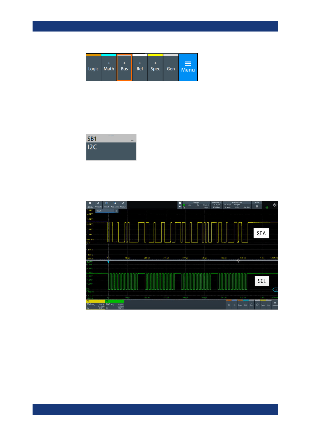
Protocol analysis
R&S
®
MXO 5 Series
323User Manual 1802.3369.02 ─ 02
2. Select the tab of the bus that you want to set up, for example "SB1".
3. Tap the "Protocol type" button. Select the protocol: "I2C".
4. Tap on "State" to enable the decoding.
An I2C shortcut appears at the bottom left of the screen. Tap on the shortcut for a
quick access to the "I2C" dialog settings.
5. Tap on each active wire and select the correct channels: "SDA source" and "SCL
source".
6. Check that the signals are on the screen.
If not try adjusting the vertical and horizontal settings.
7. Set the logical thresholds:
a) Tap "Threshold setup". The threshold dialog opens.
b) For each wire, set the threshold value. A typical value is 1.65 V.
c) If necessary, set the hysteresis value for the wires.
d) Optionally, tap on "Show threshold lines".
I²C (option R&S
MXO5-K510)
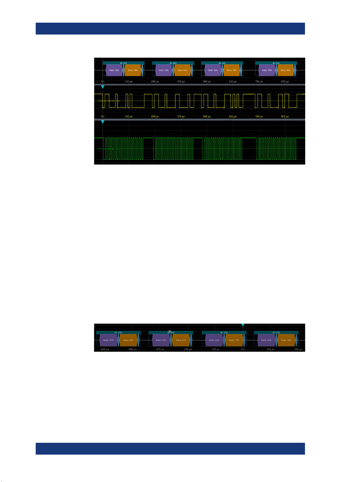
Protocol analysis
R&S
®
MXO 5 Series
324User Manual 1802.3369.02 ─ 02
13.3.6.2 Triggering on I2C
Prerequisites: A bus is configured for the I2C signal to be analyzed. See Chap-
ter 13.3.6.1, "Configuring I2C signals", on page 322.
1. Open "Menu" > "Trigger".
2. Set "Trigger on" to "Single event".
3. Ensure that the "Source" is set to the configured serial bus, e.g. "Serial bus 1".
4. Select the "Type".
5. Define additional settings for more complex trigger types: "No Ack", "Address",
"Data", "Address + Data".
a) Tap on "Set details".
b) Set the "Data" condition and "Value".
c) Set the "Position".
In the following example a decode for triggering on triggered on "Data" = 0x75,
"Position" = 1.
Figure 13-9: Trigger on Type=Data, Data=0x75 and Position=1
13.3.6.3 Exporting decode results
Once a decode has been completed, you can export the decode results of the
I²C (option R&S
MXO5-K510)

Protocol analysis
R&S
®
MXO 5 Series
325User Manual 1802.3369.02 ─ 02
Prerequisites: A bus is configured for the I2C and decoded.
1. Tap on the "I2C" shortcut.
2. Tap on the "Shortcuts" tab.
3. Tap "Export results".
4. If necessary, enable "Include details".
5. If necessary, enable "Include timing".
6. Select the "File type".
An export file is saved in the selected directory.
The I2C export files contain the following fields:
●
A list of all decoded frames:
– Index
– Start
– Stop
– State
– Address type
– Address value
– R/W bit
– Bit rate
●
The details frames include the following fields:
– Index
– Formatted data
– ACK bit start
– ACK bit
Example of I2C export file
Index,Start,Stop,State,Address type,Address value,R/W bit,Bit rate
1,-0.25,-0.24945,'OK','BIT10',188h,'WRIT',100000
2,-0.24944,-0.249,'OK','BIT10',1h,'READ',100000
3,-0.24899,-0.24866,'OK','BIT7',5Bh,'READ',100000
4,-0.24865,-0.24821,'OK','BIT7',4Ah,'WRIT',100000
5,-0.2482,-0.24765,'OK','BIT10',188h,'WRIT',100000
6,-0.24764,-0.2472,'OK','BIT10',1h,'READ',100000
Details frame 1
Index,Formatted data,Ack bit start,Ack bit
1,DEh,-0.2497,'ACK'
2,C2h,-0.24959,'ACK'
3,B3h,-0.24948,'ACK'
Details frame 2
Index,Formatted data,Ack bit start,Ack bit
I²C (option R&S
MXO5-K510)

Protocol analysis
R&S
®
MXO 5 Series
326User Manual 1802.3369.02 ─ 02
1,E1h,-0.24925,'ACK'
2,C2h,-0.24914,'ACK'
3,B3h,-0.24903,'ACK'
Details frame 3
Index,Formatted data,Ack bit start,Ack bit
1,E1h,-0.2488,'ACK'
2,C2h,-0.24869,'ACK'
Details frame 4
Index,Formatted data,Ack bit start,Ack bit
1,F1h,-0.24846,'ACK'
2,C4h,-0.24835,'ACK'
3,B3h,-0.24824,'NACK'
Details frame 5
Index,Formatted data,Ack bit start,Ack bit
1,DEh,-0.2479,'ACK'
2,C2h,-0.24779,'ACK'
3,B3h,-0.24768,'ACK'
13.4 UART (option R&S MXO5-K510)
The Universal Asynchronous Receiver/Transmitter UART converts a word of data into
serial data, and vice versa. It is the base of many serial protocols such as RS-232.
Required options and equipment
For performing UART decode measurements, you need the following equipment:
●
R&S MXO 5 with 2 available channels. The channels can be a combination of the
following:
– Analog channels (C1-C4)
– Logic channels (D0-D15) (requires option R&S MXO5-B1)
●
Option R&S MXO5-K510
●
Two probes
13.4.1 About the UART / RS-232 interface
The UART uses only one line, or two lines for transmitter and receiver.
UART (option R&S
MXO5-K510)

Protocol analysis
R&S
®
MXO 5 Series
327User Manual 1802.3369.02 ─ 02
Data transfer
[Data8]
[Parity]
Stop[Data7][Data6][Data5]
Data4Data3Data2Data1Data0
Start
Figure 13-10: Bit order in a UART word (symbol)
●
The start bit is a logic 0.
●
The stop bits and the idle state are always logic 1.
The UART protocol has no clock for synchronization. The receiver synchronizes by the
start and stop bits, and the bit rate that must be known to the receiver.
Trigger
The R&S MXO 5 can trigger on specified parts of UART serial signals:
●
Start bit
●
Parity errors, and breaks
●
A serial pattern at any or a specified position
13.4.2 UART configuration
13.4.2.1 UART configuration settings
Access: [Apps] key > "Protocol" tab > "UART / RS232" > "Setup".
UART (option R&S MXO5-K510)
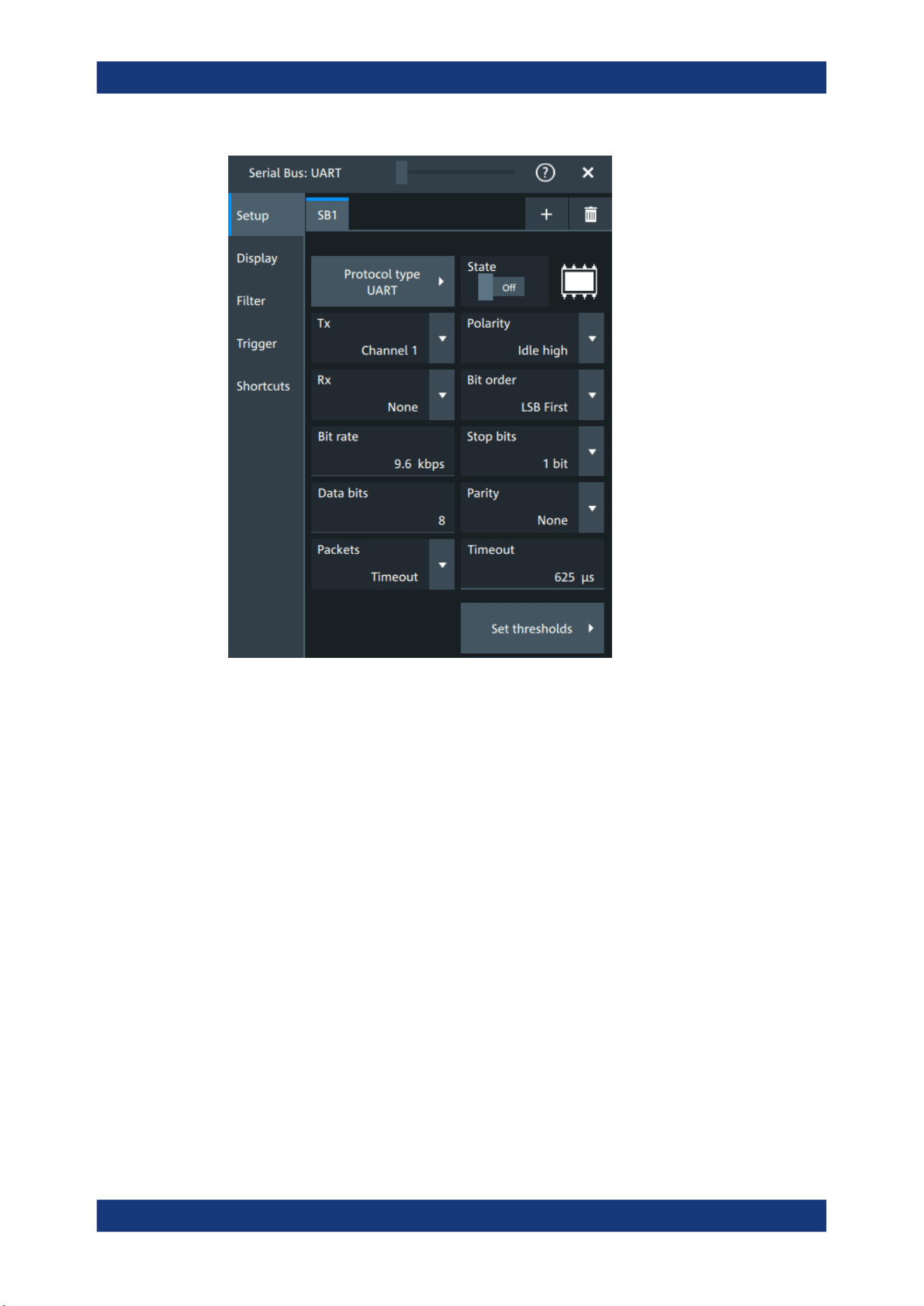
Protocol analysis
R&S
®
MXO 5 Series
328User Manual 1802.3369.02 ─ 02
Protocol type
Displays the protocol type to be decoded.
Remote command:
SBUS<sb>:TYPE on page 645
State
Enables the decoding of the selected bus. The signal icon of the bus appears on the
signal bar.
Source: Tx, Rx
Select the input channels for the transmitter and receiver signals.
Do not combine a reference waveform with channel or math waveform because the
time correlation of these waveforms might differ.
Remote command:
SBUS<sb>:UART:TX:SOURce on page 690
SBUS<sb>:UART:RX:SOURce on page 688
Bit order
Selects the bit order, which determines if the data of the messages starts with MSB
(most significant bit) or LSB (least significant bit).
Remote command:
SBUS<sb>:UART:BORDer on page 686
UART (option R&S
MXO5-K510)

Protocol analysis
R&S
®
MXO 5 Series
329User Manual 1802.3369.02 ─ 02
Polarity
Defines the logic levels of the bus. The idle state corresponds to a logic 1. The start bit
corresponds to a logic 0. "Idle high" (high=1) is used, for example, for control signals,
while "Idle low" (low=1) is defined for data lines (RS-232).
Remote command:
SBUS<sb>:UART:POLarity on page 688
Bit rate
Sets the number of transmitted bits per second.
Remote command:
SBUS<sb>:UART:BITRate on page 686
Stop bits
Sets the number of stop bits: 1 or 1.5 or 2 stop bits are possible.
Remote command:
SBUS<sb>:UART:SBIT on page 689
Data bits
Sets the number of data bits of a word in a range from 5 bits to 8 bits. If no parity bit is
used, then 9 data bits are possible.
Remote command:
SBUS<sb>:UART:SSIZe on page 689
Parity
Defines the optional parity bit that is used for error detection.
"None"
No parity bit is used.
"Odd"
The parity bit is set to "1" if the number of data bits set to "1" is even.
"Even"
The parity bit is set to "1" if the number of data bits set to "1" is odd.
"Mark"
The parity bit is always a logic 1.
"Space"
The parity bit is always a logic 0.
"Don't care"
The parity is ignored.
Remote command:
SBUS<sb>:UART:PARity on page 687
Packets
Allows you to define packets of several words in the data stream.
"None"
Packets are not considered.
"End word"
Defines a pattern as end condition of a packet, for example, a
reserved word like CR or LF. The bit pattern editor provides frequently
used values in the "Predefined values" list below the pattern table.
A new packet starts with the first start bit after the defined end pat-
tern.
"Timeout"
Defines a timeout between a stop bit and the next start bit. Enter the
minimum time that marks the end of a packet.
A new packet starts with the first start bit after the timeout.
UART (option R&S MXO5-K510)
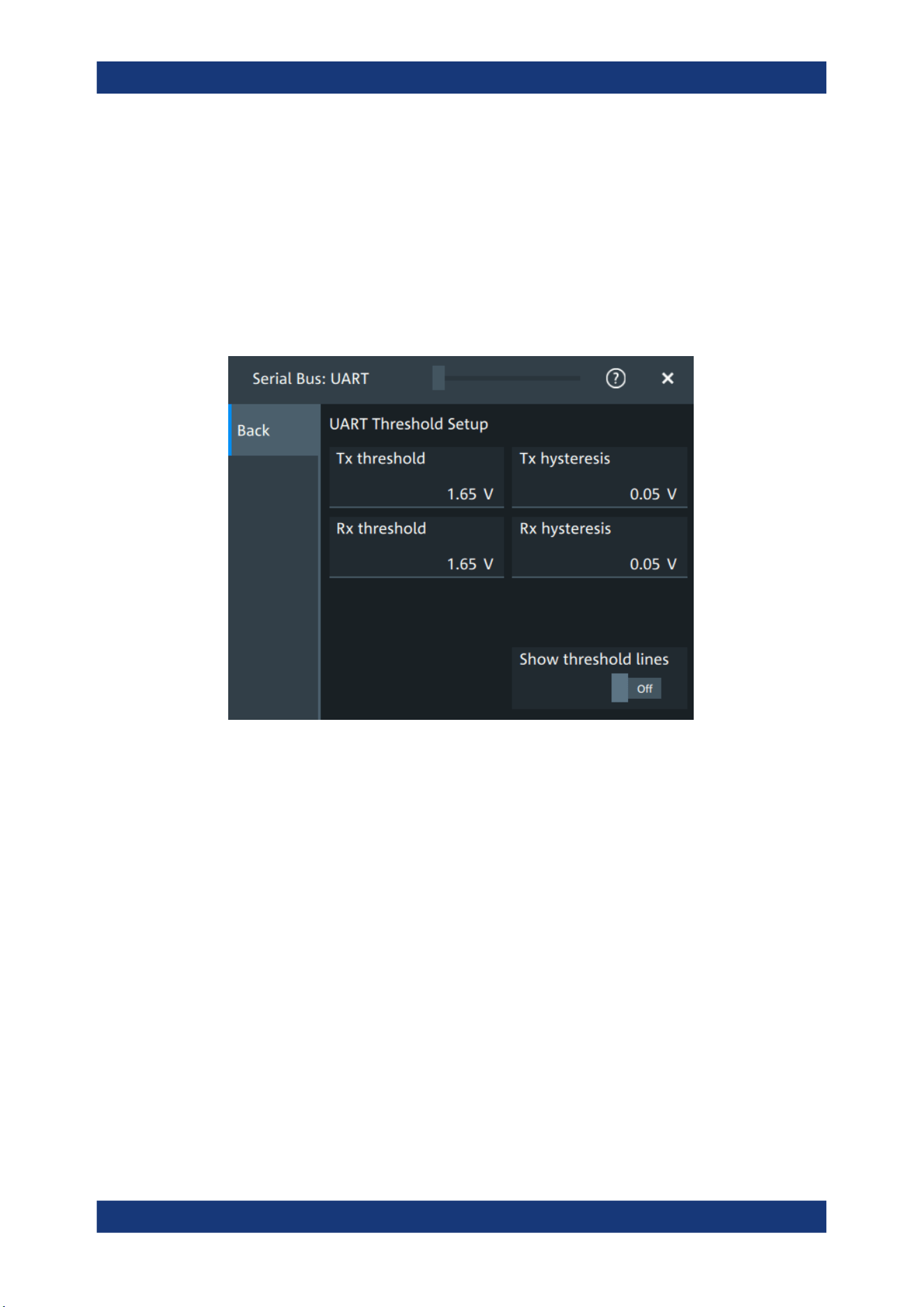
Protocol analysis
R&S
®
MXO 5 Series
330User Manual 1802.3369.02 ─ 02
Remote command:
SBUS<sb>:UART:PACKets on page 687
SBUS<sb>:UART:TOUT on page 690
SBUS<m>:UART:EWORd on page 687
Threshold
Press "Set thresholds", to open the "Threshold setup" dialog.
Enter the value directly in the field of the threshold setup dialog.
Additional to the threshold, you can also set a hysteresis.
Remote command:
SBUS<sb>:UART:RX:HYSTeresis on page 688
SBUS<sb>:UART:RX:THReshold on page 689
SBUS<sb>:UART:TX:HYSTeresis on page 690
SBUS<sb>:UART:TX:THReshold on page 690
Show threshold lines ← Threshold
If enabled, the threshold lines are displayed in the diagram.
The label of the threshold line is set according to the signal that it is referring to.
Remote command:
SBUS<m>:THReshold on page 646
13.4.2.2 Display settings
For details about the display settings, see Chapter 13.1.3, "Display", on page 288.
UART (option R&S
MXO5-K510)
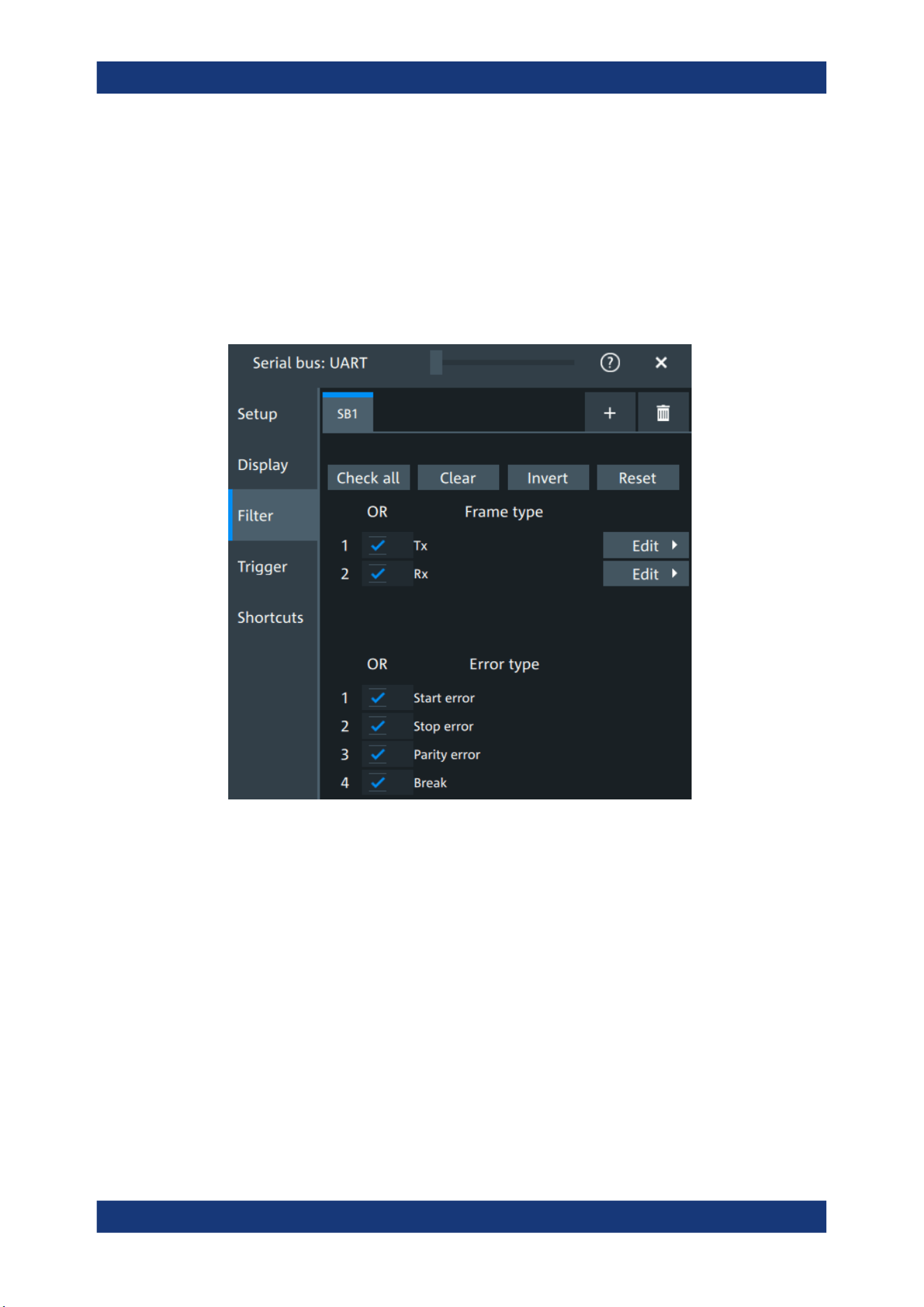
Protocol analysis
R&S
®
MXO 5 Series
331User Manual 1802.3369.02 ─ 02
13.4.2.3 Shortcuts
For details about the available shortcuts, see Chapter 13.1.6, "Shortcuts",
on page 290.
13.4.3 UART filter
Access:[Apps] key > "Protocol" tab >"UART / RS232" > "Filter" tab
In the "Filter" tab, you can define the settings to display only the frames that match the
selected filter conditions.
Check all, Clear, Invert, Reset
The following settings help you select the frames and errors you want to filter for. Only
the frames and error types that match the selected filter conditions are displayed.
"Check all"
Enables the filter for all available frames and error types.
"Clear"
Disables the filter for all available frames and error types.
"Invert"
Inverts the current state of the frame and error types: all frames and
error types that were enabled are disabled and vice versa.
"Reset"
Resets the state of the selected frames and error types.
Frame type
Selects the frame type that you want to display. You can filter all enabled frame types
simultaneously.
UART (option R&S
MXO5-K510)
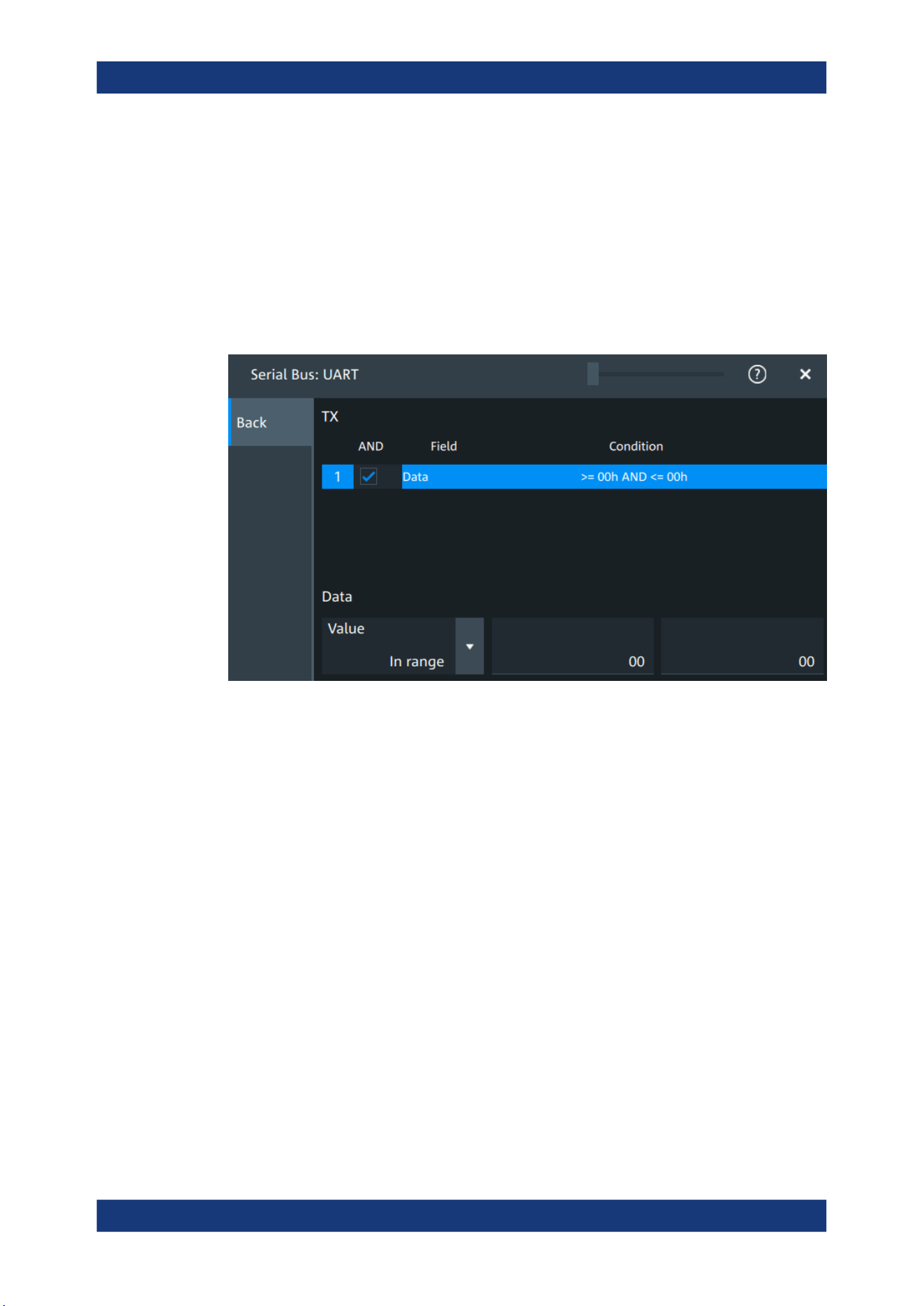
Protocol analysis
R&S
®
MXO 5 Series
332User Manual 1802.3369.02 ─ 02
For each frame type, you can also specify conditions for the value of the fields in the
"Edit" dialog.
The available frames are "Tx", "Rx".
Remote command:
SBUS<sb>:UART:FILTer:FRAMe<fr>:ENABle on page 697
SBUS<sb>:UART:FILTer:FRENable on page 697
Edit
Opens a dialog to define the details of the selected frame.
"Field"
Enables the field type that you want to filter on for the selected frame.
The available field is "Data".
Remote command:
SBUS<sb>:UART:FILTer:FIENable on page 697
SBUS<sb>:UART:FILTer:FRAMe<fr>:FLD<fl>:ENABle
on page 697
"Condition"
Displays the value condition for the selected field.
Remote command:
SBUS<sb>:UART:FILTer:FRAMe<fr>:FLD<fl>:BIT
on page 696
UART (option R&S MXO5-K510)

Protocol analysis
R&S
®
MXO 5 Series
333User Manual 1802.3369.02 ─ 02
"Data"
The data setup consists of a comparison condition and one or two
data patterns.
Remote command:
SBUS<sb>:UART:FILTer:FRAMe<fr>:FLD<fl>:DMAX
on page 696
SBUS<sb>:UART:FILTer:DMAX on page 696
SBUS<sb>:UART:FILTer:FRAMe<fr>:FLD<fl>:DMIN
on page 696
SBUS<sb>:UART:FILTer:DMIN on page 696
SBUS<sb>:UART:FILTer:FRAMe<fr>:FLD<fl>:DOPerator
on page 695
SBUS<sb>:UART:FILTer:DOPerator on page 695
"Index"
The index setup consists of a comparison condition and one or two
index values.
Remote command:
SBUS<sb>:UART:FILTer:FRAMe<fr>:FLD<fl>:IMAX
on page 694
SBUS<sb>:UART:FILTer:IMAX on page 694
SBUS<sb>:UART:FILTer:FRAMe<fr>:FLD<fl>:IMIN
on page 694
SBUS<sb>:UART:FILTer:IMIN on page 694
SBUS<sb>:UART:FILTer:FRAMe<fr>:FLD<fl>:IOPerator
on page 695
SBUS<sb>:UART:FILTer:IOPerator on page 695
Error type
Enables filtering on the selected error type.
Available error types are "Start error", "Stop error", "Parrity error", "Break".
Remote command:
SBUS<sb>:UART:FILTer:ERRor<n>:ENABle on page 695
13.4.4 UART trigger
13.4.4.1 UART trigger settings
Access: [Apps] > "Protocol" > "UART" > "Shortcuts" > "Setup trigger"
UART (option R&S MXO5-K510)
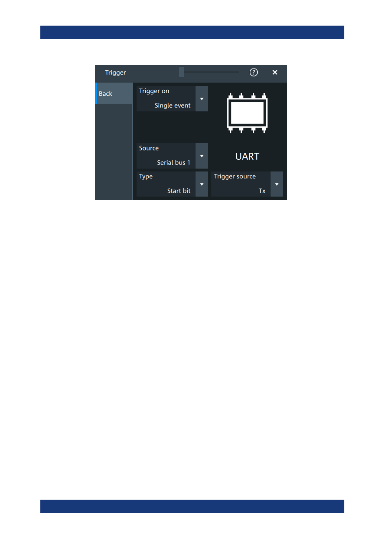
Protocol analysis
R&S
®
MXO 5 Series
334User Manual 1802.3369.02 ─ 02
Type
Selects the trigger condition.
Some trigger types have additional settings that can be defined. In this case, the "Set
details" button appears next to "Type" the function. Open it for a detailed definition of
the trigger conditions.
"Start bit"
Triggers on a start bit. The start bit is the first low bit after a stop bit.
"Packet start"
Triggers on the begin of a data packet.
"Data"
Trigger on a serial pattern at a defined position in the data packet.
The pattern can include several subsequent symbols (data frames).
"Parity error"
Triggers on a parity error indicating a transmission error. This trigger
type is only available if a parity is configured for the UART bus.
"Break condi-
tion"
Triggers if a start bit is not followed by a stop bit, the data line
remains at logic 0 for longer than a UART word.
"Stop error"
Triggers if the stop bit is a logic 0.
Remote command:
TRIGger:UART:TYPE on page 693
Trigger source
Selects the transmitter or receiver line as trigger source.
Remote command:
TRIGger:UART:SOURce on page 693
Data conditions
Specify the data conditions if the trigger type is set to "Data".
Data ← Data conditions
Selects the operator for the "Data" pattern.
Remote command:
TRIGger:UART:FCONdition on page 692
UART (option R&S
MXO5-K510)
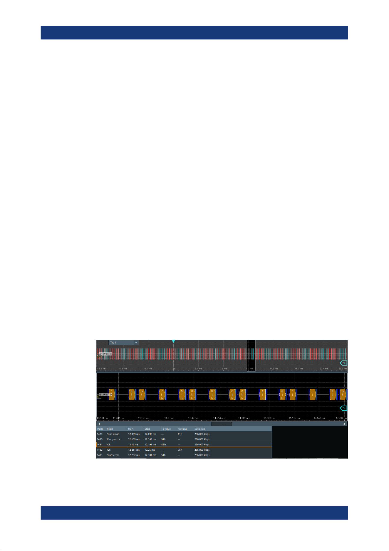
Protocol analysis
R&S
®
MXO 5 Series
335User Manual 1802.3369.02 ─ 02
Value ← Data conditions
Specifies the data pattern to be found on the specified trigger source. Enter the words
in MSB first bit order.
Remote command:
TRIGger:UART:DATA on page 692
Position ← Data conditions
Sets the number of words before the first word of interest. These offset words are
ignored.
The setting is available if packet detection is enabled in the protocol configuration.
Remote command:
TRIGger:UART:DPOSition on page 692
13.4.5 UART decode results
When the configuration of the serial bus is complete, the signal can be decoded:
1. Open the "Serial Bus" dialog for the respective bus.
2. In the "Setup" tab, enable "State".
3. In the "Display" tab, enable "Show decode table".
For a description of the display settings, see also Chapter 13.1.3, "Display",
on page 288.
The instrument captures and decodes the signal according to the standard definition
and the configuration settings.
The color-coding of the various protocol sections and errors simplifies the interpretation
of the visual display. The decode information condenses or expands, depending on the
horizontal scale. Various data formats are available to show the result values.
Figure 13-11: Decoded and binary UART signal
UART (option R&S MXO5-K510)

Protocol analysis
R&S
®
MXO 5 Series
336User Manual 1802.3369.02 ─ 02
Blue = Start and stop bits if ok
Red = Start error, stop error, parity error
Cyan = Parity bit if ok
Gold = Word ok
Magenta = Word contains error
The "Decode results" table shows the detailed decoded data for each word.
Table 13-4: Content of the Decode results table
Column Description
Index Number of the decoded frames
State Decoding state of the word.
"Insuffcient waveform length" indicates that the word is not completely contained in
the acquisition. Change the horizontal scale, or move the reference point to the left
to get a longer acquisition.
Start Time of the word start (start bit)
Stop Time of the word stop (stop bit)
Tx value Value of the Tx word. The data format is selected below the table.
Rx value Value of the Rx word. The data format is selected below the table.
Data rate Value of the data rate
Data format
You can select various data formats for the values displayed in the decode table and in
the combs of the decoded signal.
Remote command:
●
SBUS<sb>:FORMat on page 645
Export of decode results
1. In the protocol "Shortcuts" tab, press "Export results".
The "Export results" dialog opens.
For details, see Chapter 13.1.7, "Export protocol results", on page 291.
2. Select the details that you want to export and the file format.
3. Tap "Save as".
4. Key in a name and select the file format.
Remote commands
Remote commands to retrieve decode results are described in Chapter 17.16.4.4,
"Decode results", on page 697.
13.4.6 Performing UART decoding
This chapter explains step by step how to configure and decode the UART bus.
UART (option R&S
MXO5-K510)
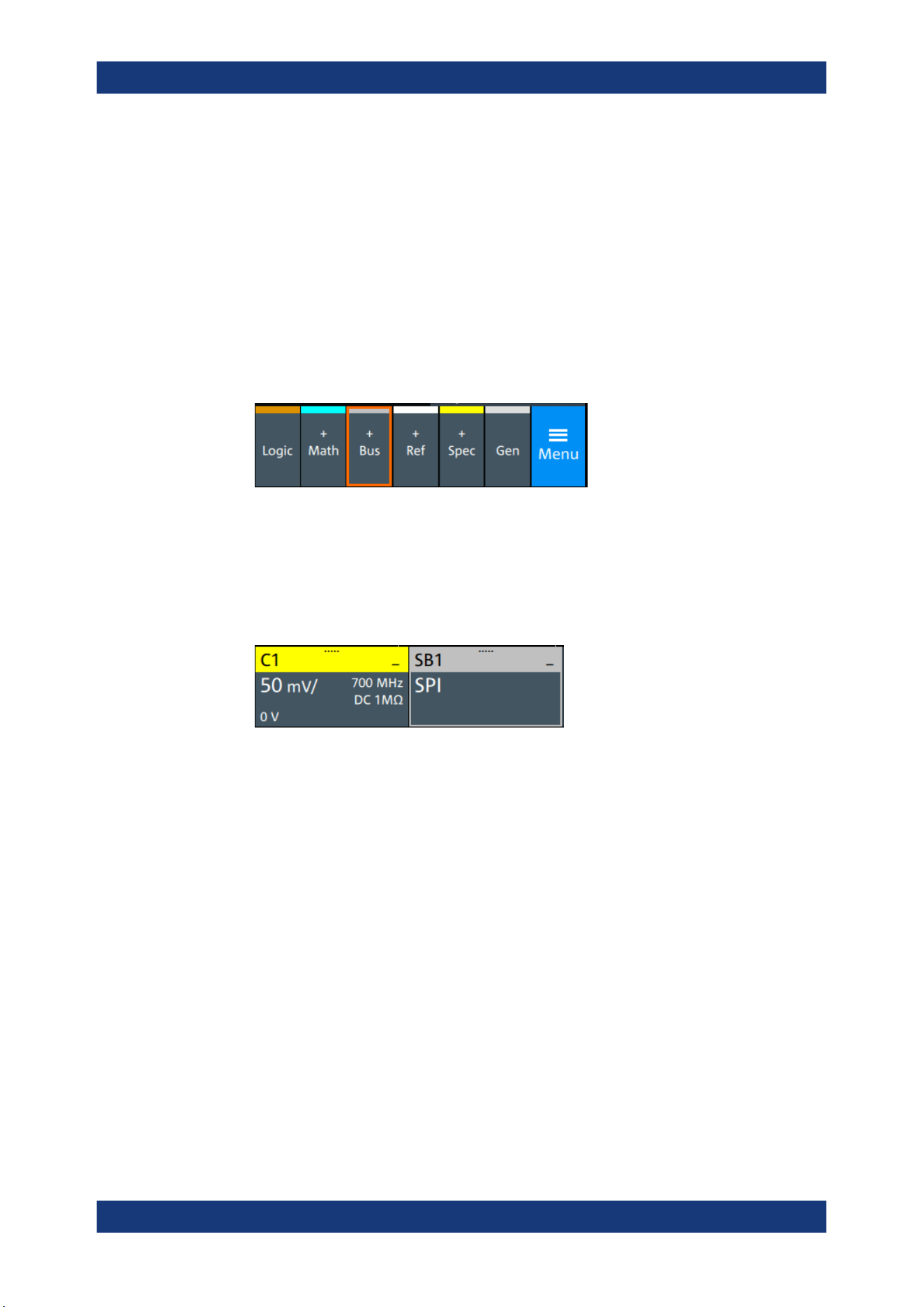
Protocol analysis
R&S
®
MXO 5 Series
337User Manual 1802.3369.02 ─ 02
For more information on decoding UART, you can also refer to the video, available on
the Rohde & Schwarz YouTube channel: Decoding UART with MXO Series Oscillo-
scope.
13.4.6.1 Configuring UART signals
For configuration, assign the lines to the input channels, and define the active states
and the logical thresholds.
For details on configuration settings, see UART configuration.
1. Tap the "Bus" activator in the bottom right of the screen.
2. Select the tab of the bus that you want to set up, for example "SB1".
3. Tap the "Protocol type" button. Select the protocol: "UART".
4. Tap on "State" to enable the decoding.
An SPI shortcut appears at the bottom left of the screen. Tap on the shortcut for a
quick access to the "UART / RS232" dialog settings.
5. Select the correct channels for each active line: "Tx" and "Rx".
6. Set the "Bit rate".
7. Set the "Data bits". Typical value is 7 or 8.
8. Set the "Stop bits". Typical value is 1.
9. Set the "Parity" to "None", "Odd" or "Even".
10. Set "Bit order" to "MSB" or "LSB first".
11. Set the "Packets".
12. Set the "Timeout".
13. Set the "Polarity" to "Idle high" or "Idle low".
14. Check that the signals are on the screen.
If not try adjusting the vertical and horizontal settings.
UART (option R&S
MXO5-K510)
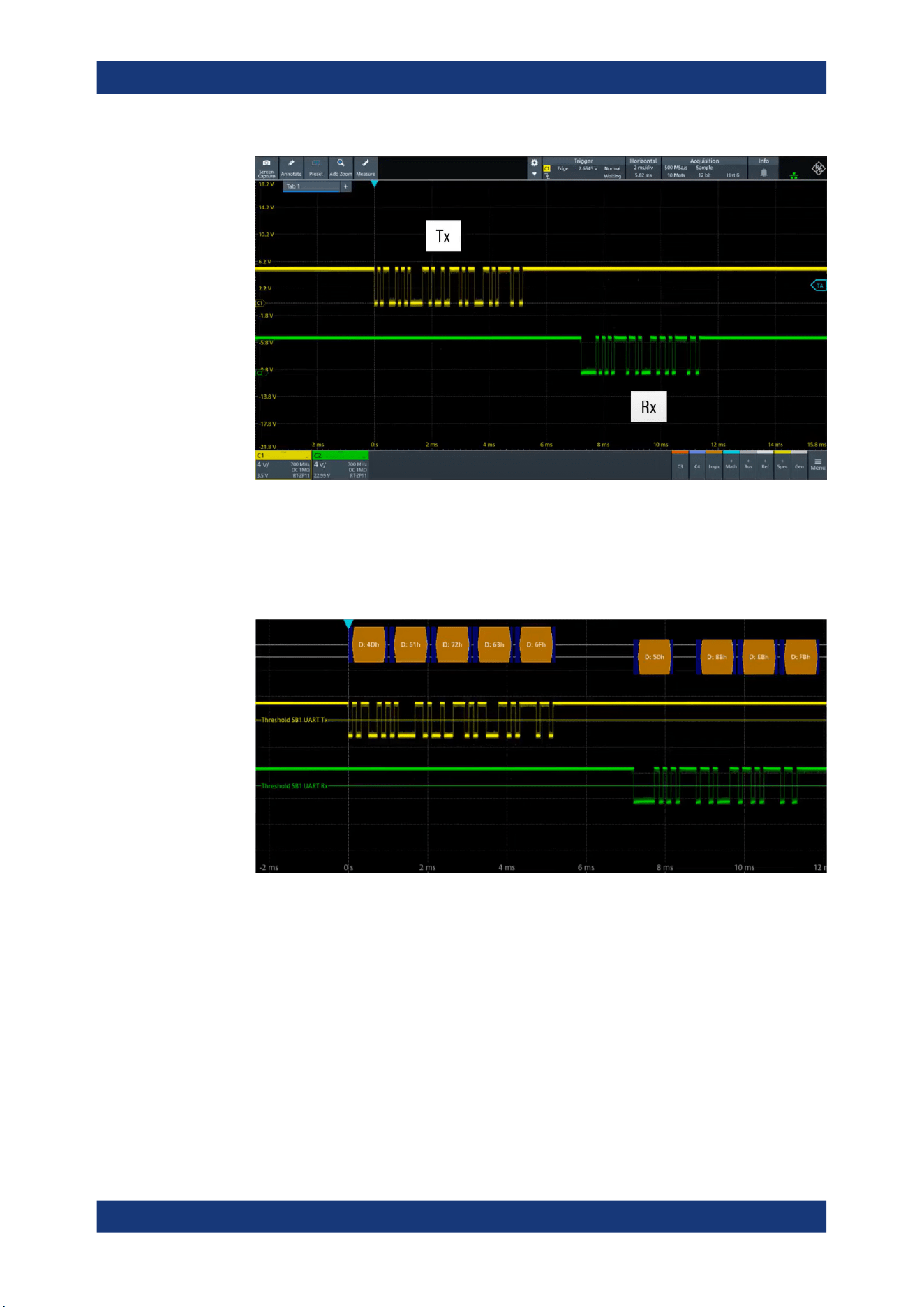
Protocol analysis
R&S
®
MXO 5 Series
338User Manual 1802.3369.02 ─ 02
15. Set the logical thresholds:
a) Tap "Threshold setup". The threshold dialog opens.
b) For each line, set the threshold value. A typical value is 2.5 V.
c) If necessary, set the hysteresis value for the wires.
d) Optionally, tap on "Show threshold lines".
13.4.6.2 Triggering on UART
Prerequisites: A bus is configured for the UART signal to be analyzed. See Configuring
UART signals.
1. Open "Menu" > "Trigger".
2. Set "Trigger on" to "Single event".
3. Ensure that the "Source" is set to the configured serial bus, e.g. "Serial bus 1".
4. Select the "Type": "Start bit", "Packet start", "Parity error", "Break condition" and
"Stop error".
UART (option R&S
MXO5-K510)
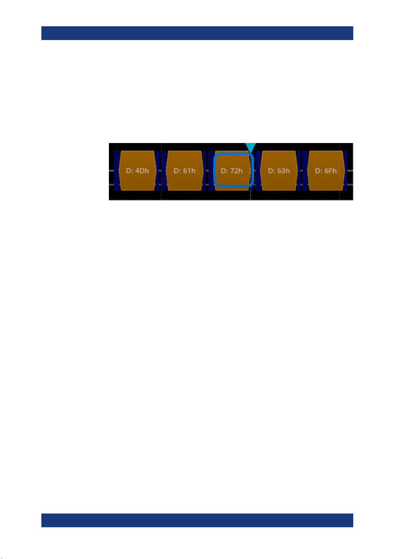
Protocol analysis
R&S
®
MXO 5 Series
339User Manual 1802.3369.02 ─ 02
5. Set "Trigger source" to "Tx" or "Rx".
6. Define additional settings for more complex trigger types ("Data"):
a) Tap on "Set details".
b) Set the "Data" condition and "Value".
c) Set the "Position".
In the following example a decode for triggering on TX triggered on "Data"= 0x72
and "Position"= 3.
Figure 13-12: Trigger on Type= Tx, Data =0x72 and Position=3
13.4.6.3 Exporting decode results
Once a decode has been completed, you can export the decode results of the
Prerequisites: A bus is configured for the UART and decoded.
1. Tap on the "UART / RS232" shortcut.
2. Tap on the "Shortcuts" tab.
3. Tap "Export results".
4. If necessary, enable "Include details".
5. If necessary, enable "Include timing".
6. Select the "File type".
An export file is saved in the selected directory.
The UART export files contain the following fields:
●
Index
●
Start
●
Stop
●
Source
●
State
●
TX value
●
RX value
●
Bit rate
UART (option R&S
MXO5-K510)

Protocol analysis
R&S
®
MXO 5 Series
340User Manual 1802.3369.02 ─ 02
Example UART export file
Index,Start,Stop,Source,State,Tx value,Rx value,Bit rate
1,-0.0629961,-0.0629531,'TX','OK',33h,---,256000
2,-0.0629453,-0.0629023,'RX','OK',---,F5h,256000
3,-0.0628945,-0.0628516,'TX','STER',C8h,---,256000
4,-0.0628438,-0.0628008,'RX','SPER',---,28h,256000
5,-0.062793,-0.06275,'TX','PRER',A8h,---,256000
13.5 CAN (option R&S MXO5-K520)
CAN is the Controller Area Network, a bus system designed by Bosch for use within
automotive network architecture, for example, for brake, power train and engine man-
agement. Today, it is also used in many other systems, for example, in industrial
machines, aerospace, subsea, merchant marine.
With the R&S MXO 5 you can decode frames from some of the most common CAN
protocols standards:
●
Classical CAN (CAN 2.0): with the standard frame format (11-bit identifier) and the
extended frame format (29-bit identifier).
●
CAN FD: CAN with flexible data rate. It is an extension of the classical CAN proto-
col and allows for increased data rates and payloads. It is backward compatible
with CAN 2.0.
●
CAN XL: an advanced version of the CAN protocol designed to handle higher data
rates and larger payloads compared to classical CAN and CAN FD.
Required options and equipment
For performing CAN decode measurements, you need the following equipment:
●
R&S MXO 5 with 1 available channel. The channel can be:
– Analog channels (C1-C4)
– Logic channels (D0-D15) (requires option R&S MXO5-B1)
●
One probe
●
Option R&S MXO5-K520
13.5.1 CAN configuration
13.5.1.1 CAN configuration settings
Access: [Apps] key > "Protocol" tab > "CAN" > "Setup".
CAN (option R&S
MXO5-K520)
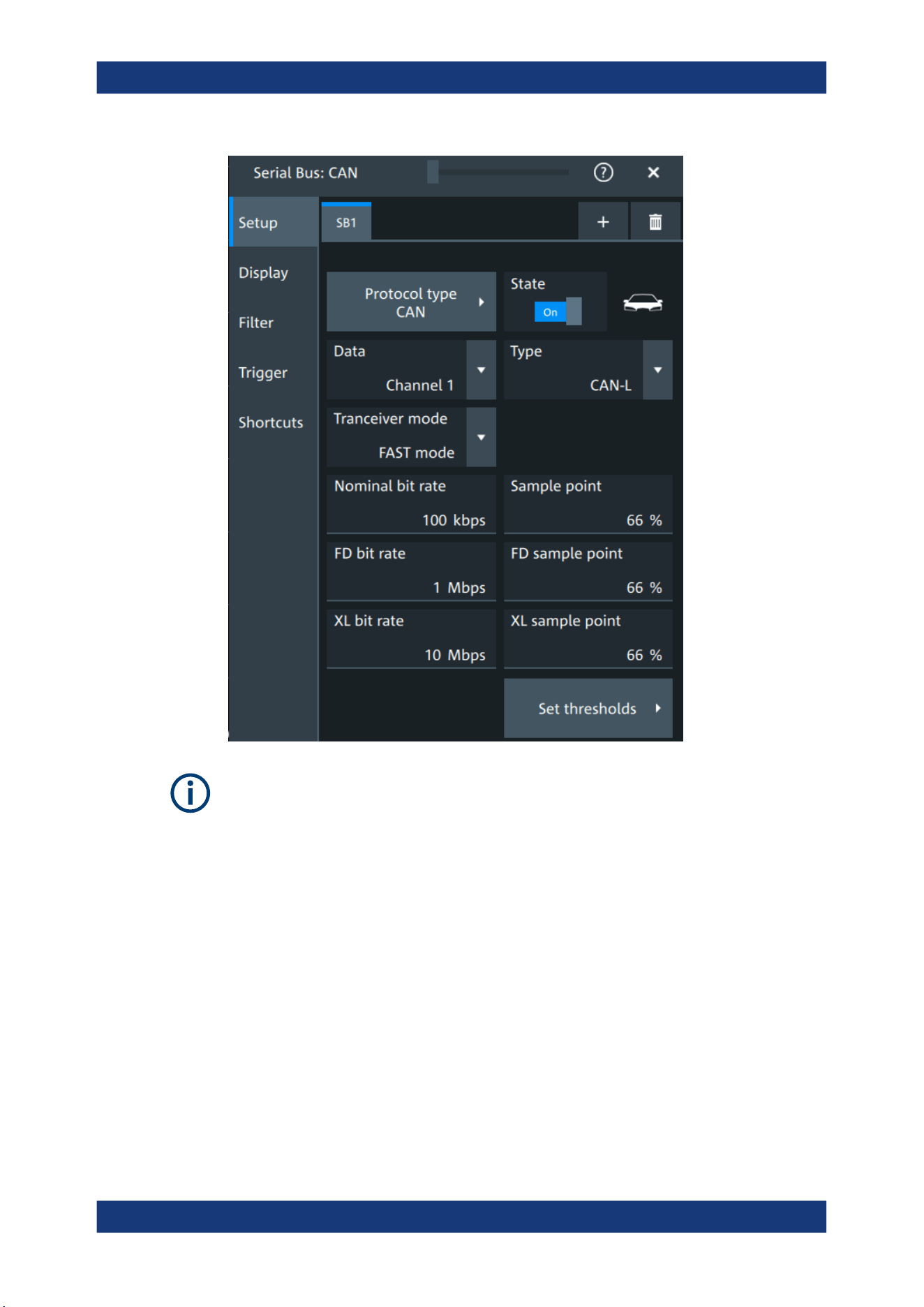
Protocol analysis
R&S
®
MXO 5 Series
341User Manual 1802.3369.02 ─ 02
Make sure that the tab of the correct serial bus is selected.
Protocol type
Displays the protocol type to be decoded.
Remote command:
SBUS<sb>:TYPE on page 645
State
Enables the decoding of the selected bus. The signal icon of the bus appears on the
signal bar.
Data
Sets the source of the selected data line.
Remote command:
SBUS<sb>:CAN:SOURce on page 702
CAN (option R&S
MXO5-K520)

Protocol analysis
R&S
®
MXO 5 Series
342User Manual 1802.3369.02 ─ 02
Type
Selects the CAN-High or CAN-Low line. CAN uses both lines for differential signal
transmission.
If you measure with a differential probe, connect the probe to both CAN-H and CAN-L
lines, and select the data "Type" = CAN-H.
If you use a single-ended probe, connect the probe to either CAN_L or CAN_H, and
select the data type accordingly.
Remote command:
SBUS<sb>:CAN:TYPE on page 701
Transceiver mode
Selects the transceiver mode for the CAN decoding.
"SIC mode"
Signal improvement capability (SIC) mode. The possible bit rate is up
to 8 Mbit.
"FAST mode"
Fast mode. The possible bit rate is up to 20 Mbit.
Remote command:
SBUS<sb>:CAN:TRCVmode on page 704
Nominal bit rate
Sets the number of transmitted bits per second.
Remote command:
SBUS<sb>:CAN:BITRate on page 701
Sample point
Sets the position of the sample point within the bit in percent of the nominal bit time.
Remote command:
SBUS<sb>:CAN:SAMPlepoint on page 702
FD bit rate
Sets the number of transmitted bits per second for the CAN FD frame.
Remote command:
SBUS<sb>:CAN:FDATa:DBITrate on page 702
FD sample point
Sets the position of the sample point within the bit in percent of the nominal bit time for
the CAN FD frame.
Remote command:
SBUS<sb>:CAN:FDATa:SAMPlepoint on page 702
XL bit rate
Sets the number of transmitted bits per second for the CAN XL frame.
Remote command:
SBUS<sb>:CAN:XDATa:DBITrate on page 704
CAN (option R&S
MXO5-K520)
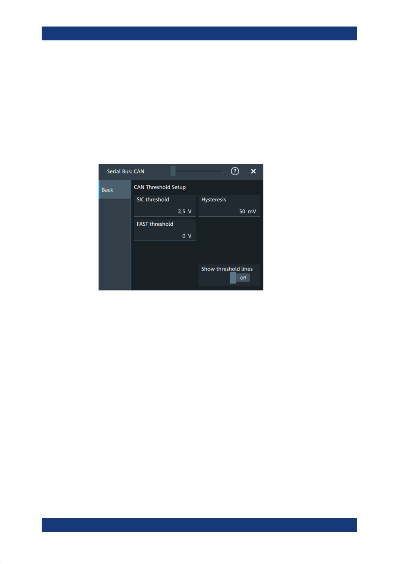
Protocol analysis
R&S
®
MXO 5 Series
343User Manual 1802.3369.02 ─ 02
XL sample point
Sets the position of the sample point within the bit in percent of the nominal bit time for
the CAN XL frame.
Remote command:
SBUS<sb>:CAN:XDATa:SAMPlepoint on page 704
Threshold
Press "Set thresholds", to open the "Threshold setup" dialog.
Enter the value directly in the field of the threshold setup dialog.
Additional to the threshold, you can also set a hysteresis.
Remote command:
SBUS<sb>:CAN:FAST:HYSTeresis on page 704
SBUS<sb>:CAN:FAST:THReshold on page 703
SBUS<sb>:CAN:SIC:HYSTeresis on page 703
SBUS<sb>:CAN:SIC:THReshold on page 703
Show threshold lines
If enabled, the threshold lines are displayed in the diagram.
The label of the threshold line is set according to the signal that it is referring to.
Remote command:
SBUS<m>:THReshold on page 646
13.5.1.2 Display settings
For details about the display settings, see Chapter 13.1.3, "Display", on page 288.
CAN (option R&S
MXO5-K520)
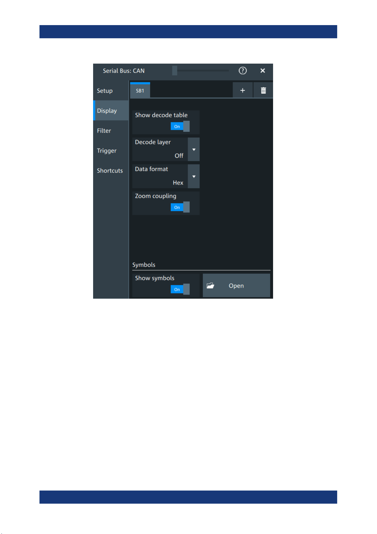
Protocol analysis
R&S
®
MXO 5 Series
344User Manual 1802.3369.02 ─ 02
Decode layer
Selects the decode layer.
Decoding is performed in several steps, and the end results are presented in the
decode table. The decode layer selects an interim step for which the decoding result is
shown in the honeycomb display.
Show symbols
You can load symbol lists, and activate its usage for decoding. As a result, an addi-
tional "Symbol" column appears in the "Decode results" table, containing the symbolic
label.
Symbol lists for CAN are available in DBC and CSV format, see CAN symbols.
Remote command:
SBUS<sb>:CAN:SYMBols on page 705
SBUS<sb>:CAN:NEWList on page 705
CAN (option R&S
MXO5-K520)

Protocol analysis
R&S
®
MXO 5 Series
345User Manual 1802.3369.02 ─ 02
13.5.1.3 CAN symbols
For the CAN protocol, you can upload symbol lists containing IDs and a symbolic name
for each node. You can load a file in one of the supported formats: DBC and CSV.
DBC files for CAN and CAN FD
Industry standard DBC files contain more information than CSV files and translate the
abstract decode results to human language. For each frame, the frame ID and the
symbolic name of the ID are given. The frames are also called messages in CAN. The
data of a CAN message can consist of several "signals". The DBC file provides the
label, unit, start bit, length and other indicators for each signal. For state-encoded sig-
nals, the meaning of the states is given.
In the following demo example, the message "EngineData" has the decimal ID
2,166,573,756 and consists of 8 data bytes. These 8 bytes are defined as 6 signals.
The first one, "PetrolLevel", starts at bit #24, has a length of 8 bit, and the unit is liter.
The signal "IdleRunning" is state-encoded. It has only one bit. The binary value 0
means "Running", and the binary value 1 means "Idle".
Example: CAN DBC file section
BO_ 2166573756 EngineData: 8 Engine
SG_ PetrolLevel : 24|8@1+ (1,0) [0|255] "l" ...
SG_ EngPower : 48|16@1+ (0.01,0) [0|350] "kW" ...
SG_ EngForce : 32|10@1+ (1,0) [0|1000] "N" ...
SG_ IdleRunning : 23|1@1+ (1,0) [0|1] "" ...
SG_ EngTemp : 16|7@1+ (2,-50) [-50|150] "degC" ....
SG_ EngSpeed : 0|13@1+ (1,0) [0|8000] "rpm" ...
....
VAL_ 2166573756 IdleRunning 0 "Running" 1 "Idle" ;
CSV files for CAN / CAN FD
Symbol list files are protocol-specific. A CSV label file for CAN protocols contains three
values for each identifier:
●
Identifier type, 11-bit or 29-bit long
●
Identifier value
●
Symbolic name of the identifier, specifying its function in the bus network.
Example: CAN CSV file
# ----------------------------------------------------------------------------
@FILE_VERSION = 1.00
@PROTOCOL_NAME = can
# ---------------------------------------------------------------------------
# Labels for CAN protocol
# Column order: Identifier type, Identifier value, Label
# ---------------------------------------------------------------------------
11,064h,Diag_Response
11,1E5h,EngineData
11,0A2h,Ignition_Info
CAN (option R&S
MXO5-K520)

Protocol analysis
R&S
®
MXO 5 Series
346User Manual 1802.3369.02 ─ 02
11,1BCh,TP_Console
11,333h,ABSdata
11,313h,Door_Left
11,314h,Door_Right
29,01A54321h,Throttle
29,13A00FA2h,LightState
29,0630ABCDh,Engine_Status
29,03B1C002h,Airbag_Status
29,01234ABCh,NM_Gateway
# ----------------------------------------------------------------------------
13.5.1.4 Shortcuts
For details about the available shortcuts, see Chapter 13.1.6, "Shortcuts",
on page 290.
13.5.2 CAN filter
Access: [Apps] key > "Protocol" tab > "CAN" > "Filter" tab
CAN (option R&S MXO5-K520)
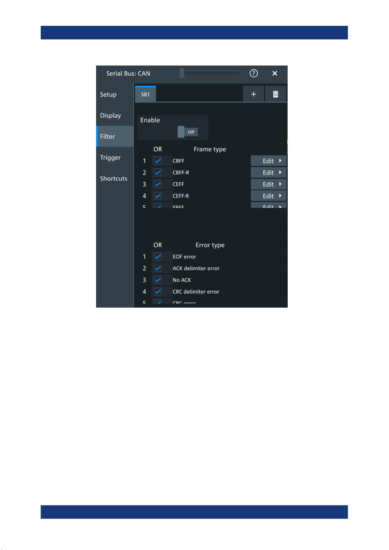
Protocol analysis
R&S
®
MXO 5 Series
347User Manual 1802.3369.02 ─ 02
In the "Filter" tab, you can define the settings to display only the frames that match the
selected filter conditions.
Check all, Clear, Invert, Reset
The following settings help you select the frames and errors you want to filter for. Only
the frames and error types that match the selected filter conditions are displayed.
"Check all"
Enables the filter for all available frames and error types.
"Clear"
Disables the filter for all available frames and error types.
"Invert"
Inverts the current state of the frame and error types: all frames and
error types that were enabled are disabled and vice versa.
"Reset"
Resets the state of the selected frames and error types.
Frame type
Selects the frame type that you want to display. You can filter all enabled frame types
simultaneously.
For each frame type, you can also specify conditions for the value of the fields in the
"Edit" dialog.
CAN (option R&S
MXO5-K520)
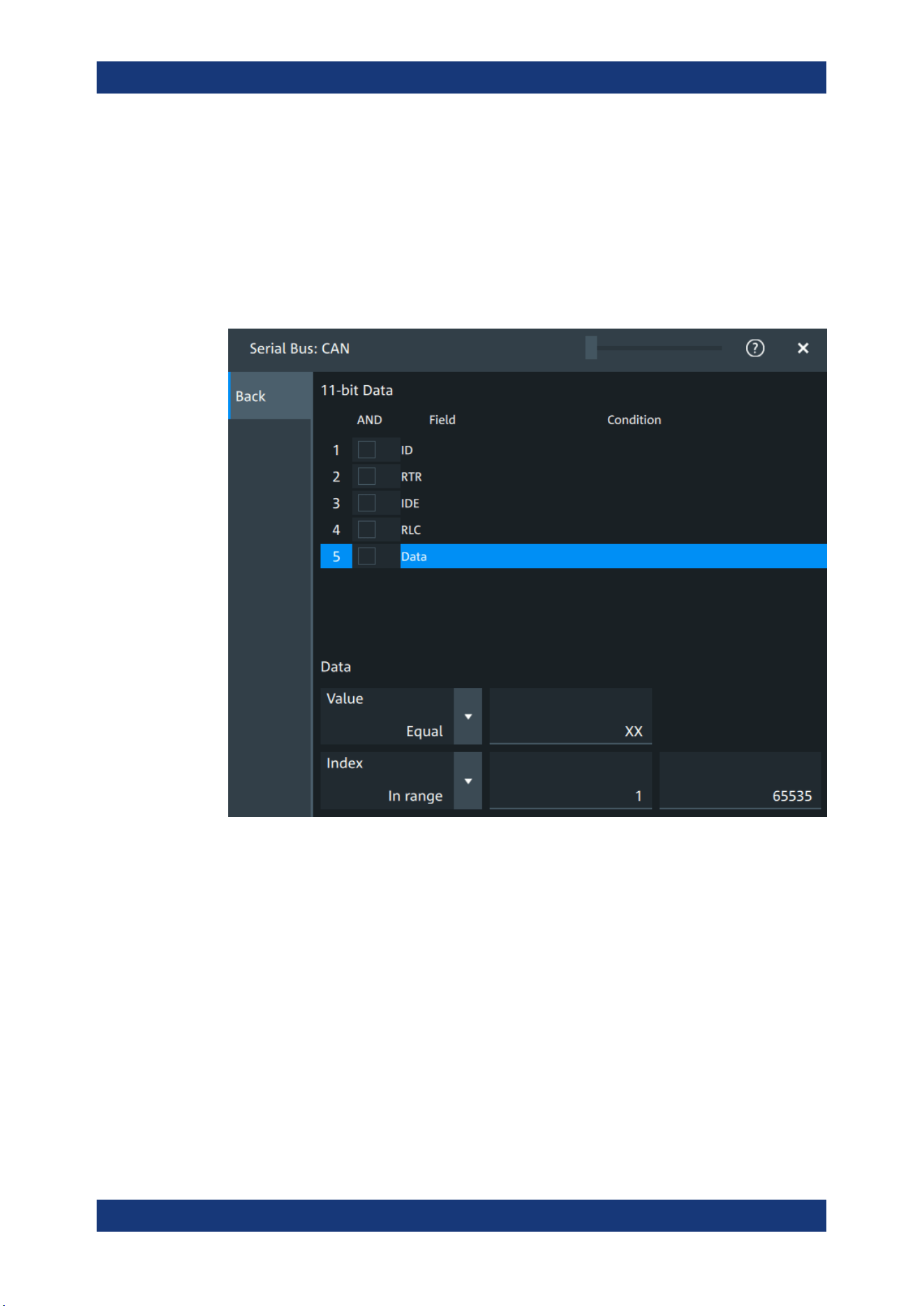
Protocol analysis
R&S
®
MXO 5 Series
348User Manual 1802.3369.02 ─ 02
Available frames are "CBFF", "CBFF-R", "CEFF", "CEFF-R", "FBFF", "FEFF", "XLFF",
"Overload" and "Error".
Remote command:
SBUS<sb>:CAN:FILTer:FRENable on page 718
SBUS<sb>:CAN:FILTer:FRAMe<fr>:ENABle on page 718
Edit
Opens a dialog to define the details of the selected frame.
"Field"
Enables the field type that you want to filter on for the selected frame.
The available fields are "ID", "RTR", "ITE", "RLC" and "Data".
Remote command:
SBUS<sb>:CAN:FILTer:FIENable on page 717
SBUS<sb>:CAN:FILTer:FRAMe<fr>:FLD<fl>:ENABle
on page 717
"Condition"
Displays the value condition for the selected field.
Remote command:
SBUS<sb>:CAN:FILTer:BIT on page 716
SBUS<sb>:CAN:FILTer:FRAMe<fr>:FLD<fl>:BIT on page 716
CAN (option R&S MXO5-K520)

Protocol analysis
R&S
®
MXO 5 Series
349User Manual 1802.3369.02 ─ 02
"Data"
The data setup consists of a comparison condition and one or two
data patterns.
Remote command:
SBUS<sb>:CAN:FILTer:DMAX on page 716
SBUS<sb>:CAN:FILTer:FRAMe<fr>:FLD<fl>:DMAX
on page 716
SBUS<sb>:CAN:FILTer:DMIN on page 716
SBUS<sb>:CAN:FILTer:FRAMe<fr>:FLD<fl>:DMIN
on page 716
SBUS<sb>:CAN:FILTer:DOPerator on page 717
SBUS<sb>:CAN:FILTer:FRAMe<fr>:FLD<fl>:DOPerator
on page 717
"Index"
The index setup consists of a comparison condition and one or two
index values.
Remote command:
SBUS<sb>:CAN:FILTer:IMAX on page 718
SBUS<sb>:CAN:FILTer:FRAMe<fr>:FLD<fl>:IMAX
on page 718
SBUS<sb>:CAN:FILTer:IMIN on page 718
SBUS<sb>:CAN:FILTer:FRAMe<fr>:FLD<fl>:IMIN
on page 718
SBUS<sb>:CAN:FILTer:IOPerator on page 719
SBUS<sb>:CAN:FILTer:FRAMe<fr>:FLD<fl>:IOPerator
on page 719
Error type
Enables filtering on the selected error type.
Remote command:
SBUS<sb>:CAN:FILTer:ERENable on page 717
SBUS<sb>:CAN:FILTer:ERRor<n>:ENABle on page 717
13.5.3 CAN trigger settings
Access: [Apps] > "Protocol" > "CAN" > "Shortcuts" > "Setup trigger"
CAN (option R&S MXO5-K520)
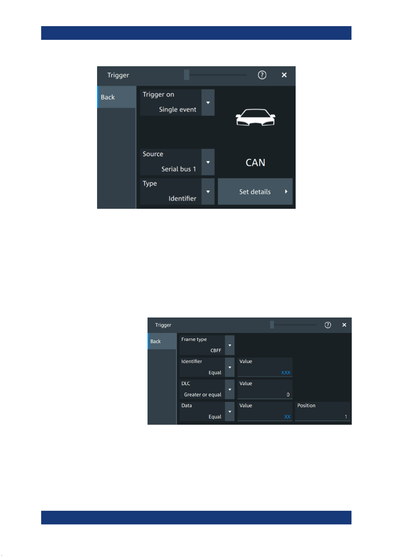
Protocol analysis
R&S
®
MXO 5 Series
350User Manual 1802.3369.02 ─ 02
Type
Selects the trigger type for CAN analysis.
Some trigger types have additional settings that can be defined. In this case, the "Set
details" button appears next to "Type" the function. Open it for a detailed definition of
the trigger conditions.
"Start of frame"
Triggers on the first edge of the dominant SOF bit (synchronization
bit).
"End of frame"
Triggers on the end of frame.
"Frame type"
Triggers on a specified frame type (data, remote, error, or overload).
For data and remote frames, also the identifier format is considered.
CAN (option R&S MXO5-K520)
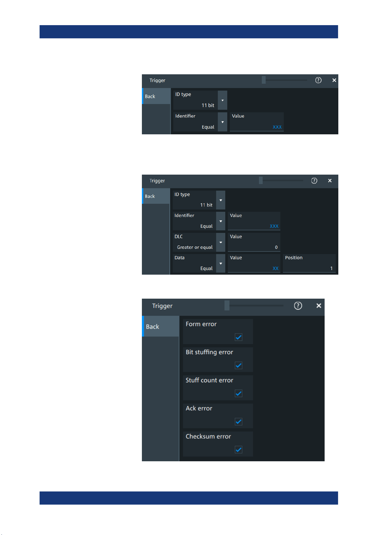
Protocol analysis
R&S
®
MXO 5 Series
351User Manual 1802.3369.02 ─ 02
"Identifier"
Sets the trigger to a specific message identifier or an identifier range.
"Identifier + Data"
Sets the trigger to a combination of identifier and data condition. The
instrument triggers at the end of the last byte of the specified data
pattern.
"Error condition"
Identifies various errors in the frame.
CAN (option R&S MXO5-K520)
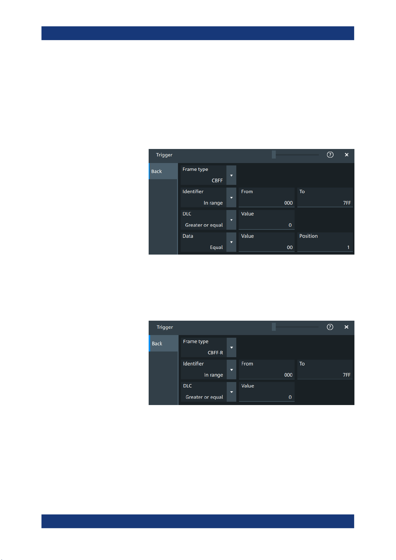
Protocol analysis
R&S
®
MXO 5 Series
352User Manual 1802.3369.02 ─ 02
Remote command:
TRIGger:CAN:TYPE on page 707
Frame type
CAN has different frame types which can be used as trigger condition. Depending on
the selected frame, you can specify further parameters.
"CBFF"
Classical base frame format data: supports a length of 11 bit for the
CAN identifier. The data frame is the only frame for actual data trans-
mission.
Figure 13-13: Settings for CBFF and CEFF frames
"CBFF-R"
Classical base frame format remote: supports a length of 11 bit for the
CAN identifier.
The remote frame initiates the transmission of data by another node.
The frame format is the same as of data frames but without the data
field.
Figure 13-14: Settings for CBFF-R and CEFF-R frames
"CEFF"
Classical extended frame format data: supports a length of 29 bit for
the CAN identifier. The data frame is the only frame for actual data
transmission.
CAN (option R&S MXO5-K520)
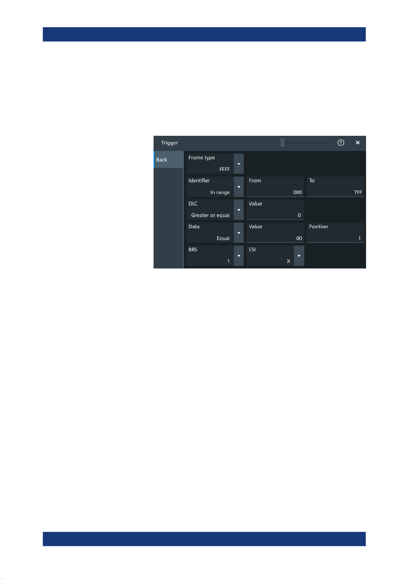
Protocol analysis
R&S
®
MXO 5 Series
353User Manual 1802.3369.02 ─ 02
"CEFF-R"
Classical extended frame format remote: supports a length of 29 bit
for the CAN identifier.
The remote frame initiates the transmission of data by another node.
The frame format is the same as of data frames but without the data
field.
"FBFF"
FD base frame format: supports a length of 11 bit for the CAN identi-
fier.
Figure 13-15: Settings for FBFF and FEFF frames
"FEFF"
FD extended frame format: supports a length of 29 bit for the CAN
identifier.
CAN (option R&S MXO5-K520)
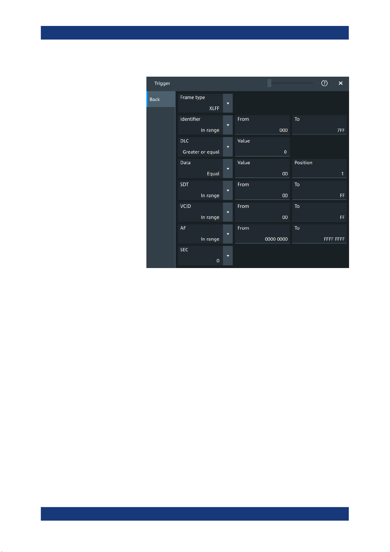
Protocol analysis
R&S
®
MXO 5 Series
354User Manual 1802.3369.02 ─ 02
"XLFF"
XL frame format: supports a length of 29 bit for the CAN identifier.
"Error"
When a node recognizes an error, it cancels transmission by sending
an error frame.
The ID type is irrelevant for error frames.
"Overload"
When a node needs a delay between data and/or remote frames, it
sends and overload frame.
The ID type is irrelevant for overload frames.
Remote command:
TRIGger:CAN:FTYPe on page 709
Identifier
Specifies the identifier pattern.
"Condition"
Sets the comparison condition to a specific value or a range.
"Value"/"From"
Specifies the value or sets the start value of a range.
"To"
Sets the maximum value of a range for "Condition" = "In range"/"Out
of range".
Remote command:
TRIGger:CAN:ICONdition on page 709
TRIGger:CAN:IMAX on page 709
TRIGger:CAN:IMIN on page 710
DLC
The data length code (DLC) defines the number of data bytes to be found. You can set
a fixed value for the DLC or define a minimum value.
CAN (option R&S
MXO5-K520)

Protocol analysis
R&S
®
MXO 5 Series
355User Manual 1802.3369.02 ─ 02
Remote command:
TRIGger:CAN:DLC on page 708
TRIGger:CAN:DLCCondition on page 708
Data pattern
Specifies the data pattern.
"Condition"
Sets the comparison condition to a specific value or a range.
"Value"
Specifies the value or sets the start value of a range.
Remote command:
TRIGger:CAN:DCONdition on page 707
TRIGger:CAN:DMIN on page 708
ID type
Selects the length of the identifier:
"11 bit"
Identifier length of the CAN base frame format. The instrument trig-
gers on the sample point of the identifier extension flag (IDE) bit.
"29 bit"
Identifier length of the CAN extended frame format. The instrument
triggers on the sample point of the remote transmission request
(RTR) bit.
"Any"
The ID type and ID pattern are not relevant for the trigger condition.
If the trigger type is "Identifier", the instrument triggers on any identi-
fier in the specified frame type.
If the trigger type is "Identifier + Data", set the "ID type" to "Any" if you
want to trigger only on data.
Remote command:
TRIGger:CAN:ITYPe on page 710
BRS, ESI
If "Frame type" = "FBFF"/"FEFF", you can trigger on specific bits.
"BRS"
The bit rate switch bit. Value 1 means that the bit rate switches from
the arbitration rate to the faster data rate.
"ESI"
The error state indicator bit. Set "X" if the bit is not relevant.
Remote command:
TRIGger:CAN:FDATa:BRS on page 712
TRIGger:CAN:FDATa:ESI on page 712
SDT
Specifies a value or a range for the service data unit type.
"Condition"
Sets the comparison condition to a specific value or a range.
"Value"/"From"
Specifies the value or sets the start value of a range.
"To"
Sets the maximum value of a range for "Condition" = "In range"/"Out
of range".
CAN (option R&S MXO5-K520)

Protocol analysis
R&S
®
MXO 5 Series
356User Manual 1802.3369.02 ─ 02
Remote command:
TRIGger:CAN:XDATa:SDT:CONDition on page 713
TRIGger:CAN:XDATa:SDT:MAX on page 713
TRIGger:CAN:XDATa:SDT:MIN on page 714
VCID
Specifies a value or a range for the virtual CAN network ID (VCID).
"Condition"
Sets the comparison condition to a specific value or a range.
"Value"/"From"
Specifies the value or sets the start value of a range.
"To"
Sets the maximum value of a range for "Condition" = "In range"/"Out
of range".
Remote command:
TRIGger:CAN:XDATa:VCID:CONDition on page 714
TRIGger:CAN:XDATa:VCID:MAX on page 715
TRIGger:CAN:XDATa:VCID:MIN on page 715
AF
Specifies a value or a range for the CAN XL acceptance field (AF).
"Condition"
Sets the comparison condition to a specific value or a range.
"Value"/"From"
Specifies the value or sets the start value of a range.
"To"
Sets the maximum value of a range for "Condition" = "In range"/"Out
of range".
Remote command:
TRIGger:CAN:XDATa:AF:CONDition on page 712
TRIGger:CAN:XDATa:AF:MAX on page 713
TRIGger:CAN:XDATa:AF:MIN on page 713
SEC
Sets a value for the simple extended content (SEC) field. It indicates, if the CAN XL
data frame uses the CADsec protocol.
Remote command:
TRIGger:CAN:XDATa:SEC on page 714
Error conditions
If a CAN detects an error, it transmits an error flag at the next bit. The R&S MXO 5
detects errors in the message and triggers on these errors even if no CAN node sends
an error flag.
CAN (option R&S MXO5-K520)
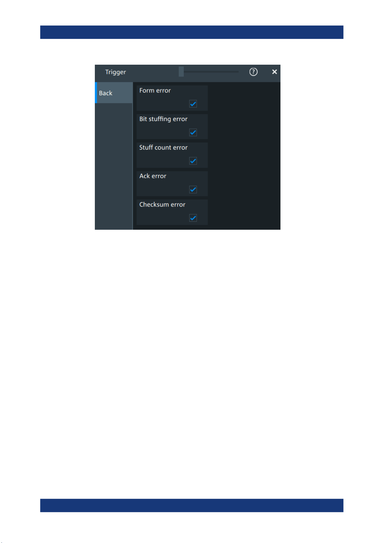
Protocol analysis
R&S
®
MXO 5 Series
357User Manual 1802.3369.02 ─ 02
"Form error"
A form error occurs when a fixed-form bit field contains one or more
illegal bits.
"Bit stuffing
error"
The frame segments Start of Frame, Arbitration Field, Control Field,
Data Field and CRC Sequence are coded by the bit stuffing method.
The transmitter automatically inserts a complementary bit into the bit-
stream when it detects five consecutive bits of identical value in the
bitstream to be transmitted. A stuff error occurs when the 6th consec-
utive equal bit level in the mentioned fields is detected.
"Stuff count
error"
A stuff bit error occurs, if more than five consecutive bits of the same
level occur on the bus.
"Ack error"
An acknowledgment error occurs when the transmitter does not
receive an acknowledgment - a dominant bit during the ACK Slot.
"Checksum
error"
CAN uses the Cyclic Redundancy Check, which is a complex check-
sum calculation method. The transmitter calculates the CRC and
sends the result in the CRC sequence. The receiver calculates the
CRC in the same way. A CRC error occurs when the calculated result
differs from the received value in the CRC sequence.
Remote command:
TRIGger:CAN:FORMerror on page 710
TRIGger:CAN:BITSterror on page 711
TRIGger:CAN:FDATa:SCERror on page 710
TRIGger:CAN:ACKerror on page 711
TRIGger:CAN:CRCerror on page 711
CAN (option R&S
MXO5-K520)
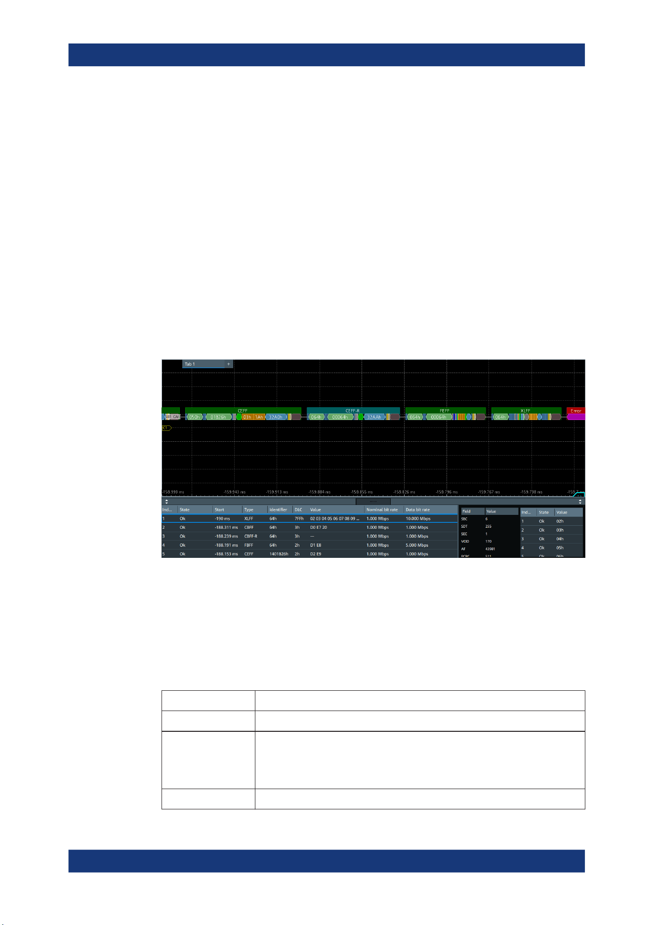
Protocol analysis
R&S
®
MXO 5 Series
358User Manual 1802.3369.02 ─ 02
13.5.4 CAN decode results
When the configuration of the serial bus is complete, the signal can be decoded:
1. Open the "Serial Bus" dialog for the respective bus.
2. In the "Setup" tab, enable "State".
3. In the "Display" tab, enable "Show decode table".
For a description of the display settings, see also Chapter 13.1.3, "Display",
on page 288.
The instrument captures and decodes the signal according to the standard definition
and the configuration settings.
The color-coding of the various protocol sections and errors simplifies the interpretation
of the visual display. The decode information condenses or expands, depending on the
horizontal scale. Various data formats are available to show the result values.
Green
= Identifier
Bright Green = DLC
Orange = Data
Blue = CRC (checksum)
Purple = End of frame
Red = Error occurred
The "Decode results" box shows the detailed decoded data for each word.
Table 13-5: Content of the Decode results table
Column Description
"Index" Number of the decoded frames
"State" Overall state of the frame.
"Insuffcient waveform length" indicates that the frame is not completely contained
in the acquisition. Change the horizontal scale, or move the reference point to the
left to get a longer acquisition.
"Start" Time of frame start
CAN (option R&S MXO5-K520)

Protocol analysis
R&S
®
MXO 5 Series
359User Manual 1802.3369.02 ─ 02
Column Description
"Type" Frame type
"Symbol" Symbolic name defined in the symbol list
"Identifier" Identifier value, hexadecimal value
"DLC" Data length code, coded number of data bytes
"Values" Value of the data frame. Remote frames do not transmit data, therefore "- - -" is
displayed
"Nominal bit rate" Number of bits per second
"Data bit rate" Number of data bits per second
Table 13-6: Content of the Detail results table
Column Description
"Field" Field type. Values depend on the decoded frame "Type", see Table 13-8.
"Value" Value of the corresponding field
Table 13-7: Content of the Data results table
Column Description
"Index" Number of the decoded fields
"State" Overall state of the frame
"Value" Value of the field
Depending on the decoded type of frame, the following fields are available:
Table 13-8: Decoded fields depending on the frame type
Frame Fields
CBFF/CBFF-R CRC: cyclic redundancy checks
CEFF/CEFF-R CRC: cyclic redundancy checks
FBFF/FEFF BRS: bit rate switch
ESI: error state indicator
SBC: stuff bit count
CRC: cyclic redundancy checks
XLFF SBC: stuff bit count
SDT: service data unit
SEC: simple extended content
VCID: virtual CAN network ID
AF: acceptance field
PCRC: preamble cyclic redundant check
FCRC: frame CRC
CAN (option R&S MXO5-K520)

Protocol analysis
R&S
®
MXO 5 Series
360User Manual 1802.3369.02 ─ 02
Data format
You can select various data formats for the values displayed in the decode table and in
the combs of the decoded signal.
Remote command:
●
SBUS<sb>:FORMat on page 645
Export of decode results
1. In the protocol "Shortcuts" tab, press "Export results".
The "Export results" dialog opens.
For details, see Chapter 13.1.7, "Export protocol results", on page 291.
2. Select the details that you want to export and the file format.
3. Tap "Save as".
4. Key in a name and select the file format.
Remote commands
Remote commands to retrieve decode results are described in Chapter 17.16.5.4,
"Decode results", on page 719.
13.5.5 Performing CAN decoding
This chapter explains step by step how to configure and decode the CAN bus.
13.5.5.1 Configuring CAN signals
For configuration, assign the lines to the input channels, and define the active states
and the logical thresholds.
For details on configuration settings, see Chapter 13.5.1, "CAN configuration",
on page 340.
1. Tap the "Bus" activator in the bottom right of the screen.
2. Select the tab of the bus that you want to set up, for example "SB1".
3. Tap the "Protocol type" button. Select the protocol: CAN.
4. Tap on "State" to enable the decoding.
An SPI shortcut appears at the bottom left of the screen. Tap on the shortcut for a
quick access to the "SPI" dialog settings.
CAN (option R&S
MXO5-K520)

Protocol analysis
R&S
®
MXO 5 Series
361User Manual 1802.3369.02 ─ 02
5. Tap on each active wire and select the correct channels: "SCLK", "MOSI", "MISO",
"CS".
6. Set "Bit order" to "MSB" or "LSB first".
7. Set "Clock polarity" to "Rising edge" (CPOL = 0) or "Falling edge" (CPOL = 1).
8. Set "MOSI polarity"/"MISO polarity" to "Active high"(CPHA = 0) or "Active
low"(CPHA = 1).
9. Set "CS polarity" to "Active high" or "Active low".
The typical value is "Active low", which means that the line is pulled low on mes-
sage start.
10. Set the "Word length". The typical value is 8.
11. Check that the signals are on the screen.
If not try adjusting the vertical and horizontal settings.
12. Set the logical thresholds:
a) Tap "Threshold setup". The threshold dialog opens.
b) For each wire, set the threshold value.
c) If necessary, set the hysteresis value for the wires.
d) Optionally, tap on "Show threshold lines".
13.5.5.2 Triggering on CAN
Prerequisites: A bus is configured for the CAN signal to be analyzed. See Chap-
ter 13.5.5.1, "Configuring CAN signals", on page 360.
1. Open "Menu" > "Trigger".
2. Set "Trigger on" to "Single event".
3. Ensure that the "Source" is set to the configured serial bus, e.g. "Serial bus 1".
4. Select the "Type".
5. For "Type" = "Frame type":
CAN (option R&S MXO5-K520)
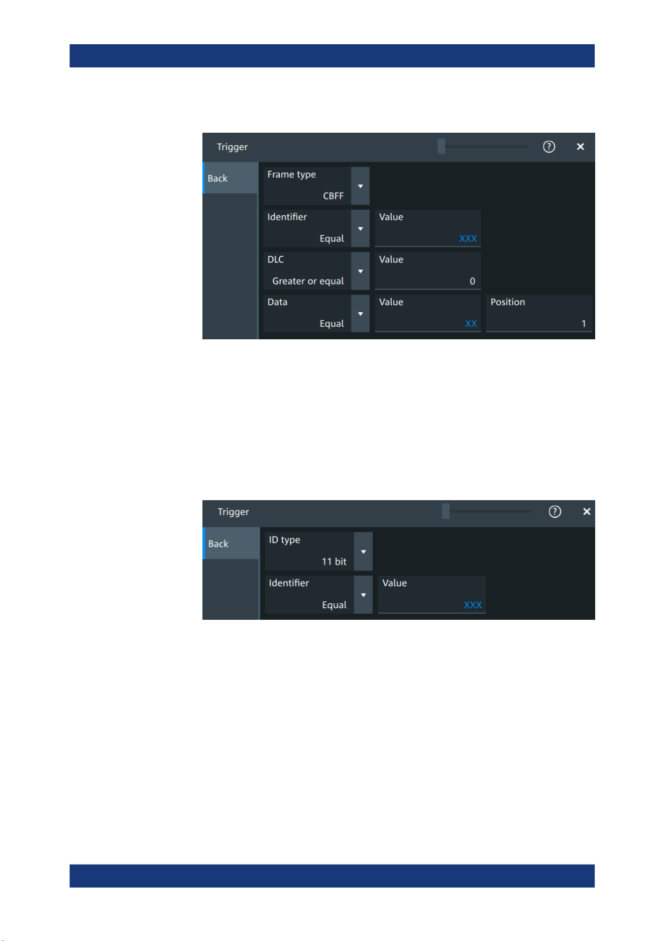
Protocol analysis
R&S
®
MXO 5 Series
362User Manual 1802.3369.02 ─ 02
a) Tap on "Set details".
b) Select the "Frame type". According to the selected type, different settings are
available.
c) Set the "Identifier" or an identifier range.
d) Set the "DLC" or a DLC range.
e) Set the "Data" or a data range.
f) Set the "ESI""ESI" value.
g) Set the "BRS" value.
6. For "Type" = "Identifier":
a) Tap on "Set details".
b) Select the "ID type".
c) Set the "Identifier" or an identifier range.
7. For "Type" = "Identifier + Data":
CAN (option R&S MXO5-K520)
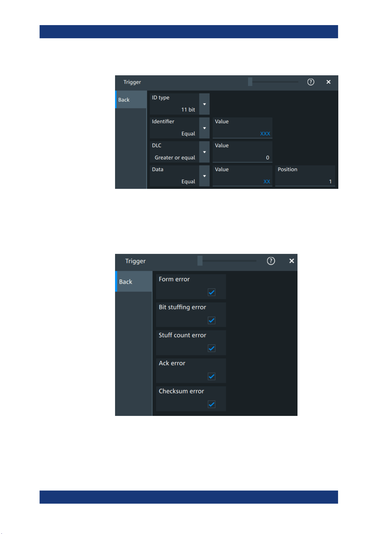
Protocol analysis
R&S
®
MXO 5 Series
363User Manual 1802.3369.02 ─ 02
a) Tap on "Set details".
b) Select the "ID type".
c) Set the "Identifier" or an identifier range.
d) Set the "DLC" or a DLC range.
e) Set the "Data" or a data range.
8. For "Type" = "Error condition":
a) Tap on "Set details".
CAN (option R&S MXO5-K520)

Protocol analysis
R&S
®
MXO 5 Series
364User Manual 1802.3369.02 ─ 02
b) Select one or more error conditions that you want to trigger on:
● "Form error"
● "Bit stuffing error"
● "Stuff count error"
● "Ack error"
● "Checksum error"
13.5.5.3 Exporting decode results
Once a decode has been completed, you can export the decode results of the
Prerequisites: A bus is configured for the CAN and decoded.
1. Tap on the "CAN" shortcut.
2. Tap on the "Shortcuts" tab.
3. Tap "Export results".
4. If necessary, enable "Include details".
5. If necessary, enable "Include timing".
6. Select the "File type".
An export file is saved in the selected directory.
The CAN export files contains the following fields:
●
A list of all decoded frames:
– Index
– Start
– Stop
– State
– Type
– ID value
– DLC
– Nominal bit rate
– Data bit rate
– CRC
– BRS
– ESI
– SBC
– SDT
– SEC
– VCID
– AF
– PCRC
CAN (option R&S
MXO5-K520)

Protocol analysis
R&S
®
MXO 5 Series
365User Manual 1802.3369.02 ─ 02
●
The details frames include the following fields:
– Index
– Data
Example of CAN export file
Index,Start,Stop,State,Type,ID value,DLC,Nominal bit rate,Data bit rate,CRC,BRS,ESI,SBC,SDT,
SEC,VCID,AF,PCRC
1,-0.19,-0.188,'OK','XLFF',064h,7FFh,1000000,10000000,0000AABBh,-,-,6h,FFh,1b,AAh,0000ABCDh,01FFh
2,-0.188311,-0.188243,'OK','CBFF',064h,3h,1000000,1000000,35CEh,-,-,-,-,-,-,-,-
3,-0.188239,-0.188195,'OK','CBFR',064h,3h,1000000,1000000,5AA0h,-,-,-,-,-,-,-,-
4,-0.188191,-0.188157,'OK','FBFF',064h,2h,1000000,5000000,035FFh,0b,1b,Eh,-,-,-,-,-
5,-0.188153,-0.188075,'OK','CEFF',01401B26h,2h,1000000,1000000,32A0h,-,-,-,-,-,-,-,-
6,-0.188071,-0.188008,'OK','CEFR',01900064h,3h,1000000,1000000,32AAh,-,-,-,-,-,-,-,-
7,-0.188004,-0.187951,'OK','FEFF',01900064h,3h,1000000,5000000,032AAh,1b,0b,Fh,-,-,-,-,-
8,-0.187947,-0.187899,'OK','XLFF',064h,046h,1000000,10000000,000032AAh,-,-,6h,03h,0b,0Ah,0000ABCFh,1FFFh
9,-0.187895,-0.187881,'INC','ERR',---,---,1000000,1000000,-,-,-,-,-,-,-,-,-
10,-0.187877,-0.187863,'UNKN','OVER',---,---,1000000,1000000,-,-,-,-,-,-,-,-,-
Details frame 2
Index,Data
1,D0h
2,E7h
3,20h
Details frame 4
Index,Data
1,D1h
2,E8h
Details frame 5
Index,Data
1,D2h
2,E9h
Details frame 7
Index,Data
1,D3h
2,EAh
3,21h
13.6 LIN (option R&S MXO5-K520)
The Local Interconnect Network (LIN) is a simple, low-cost bus system used within
automotive network architectures. LIN is usually a subnetwork of a CAN bus. The pri-
mary purpose of LIN is the integration of uncritical sensors and actuators with low-
LIN (option R&S
MXO5-K520)
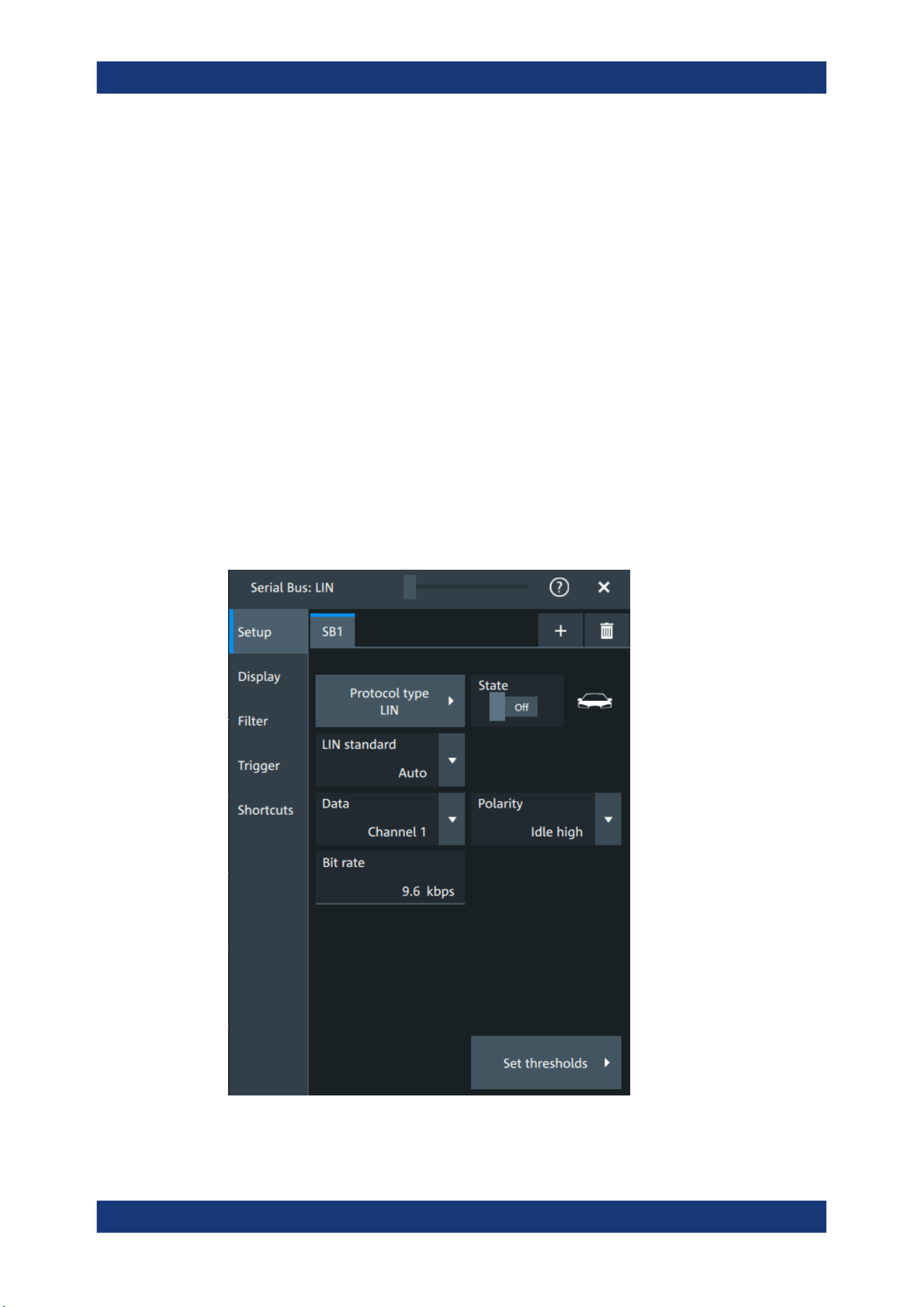
Protocol analysis
R&S
®
MXO 5 Series
366User Manual 1802.3369.02 ─ 02
bandwidth requirements. Common applications in a motor vehicle are the control of
doors, windows, wing mirrors, and wipers.
Required options and equipment
For performing LIN decode measurements, you need the following equipment:
●
R&S MXO 5 with 1 available channel. The channel can be:
– Analog channels (C1-C4)
– Logic channels (D0-D15) (requires option R&S MXO5-B1)
●
One probe
●
Option R&S MXO5-K520
13.6.1 LIN configuration
13.6.1.1 LIN configuration settings
Access: [Apps] key > "Protocol" tab > "LIN" > "Setup".
LIN (option R&S MXO5-K520)
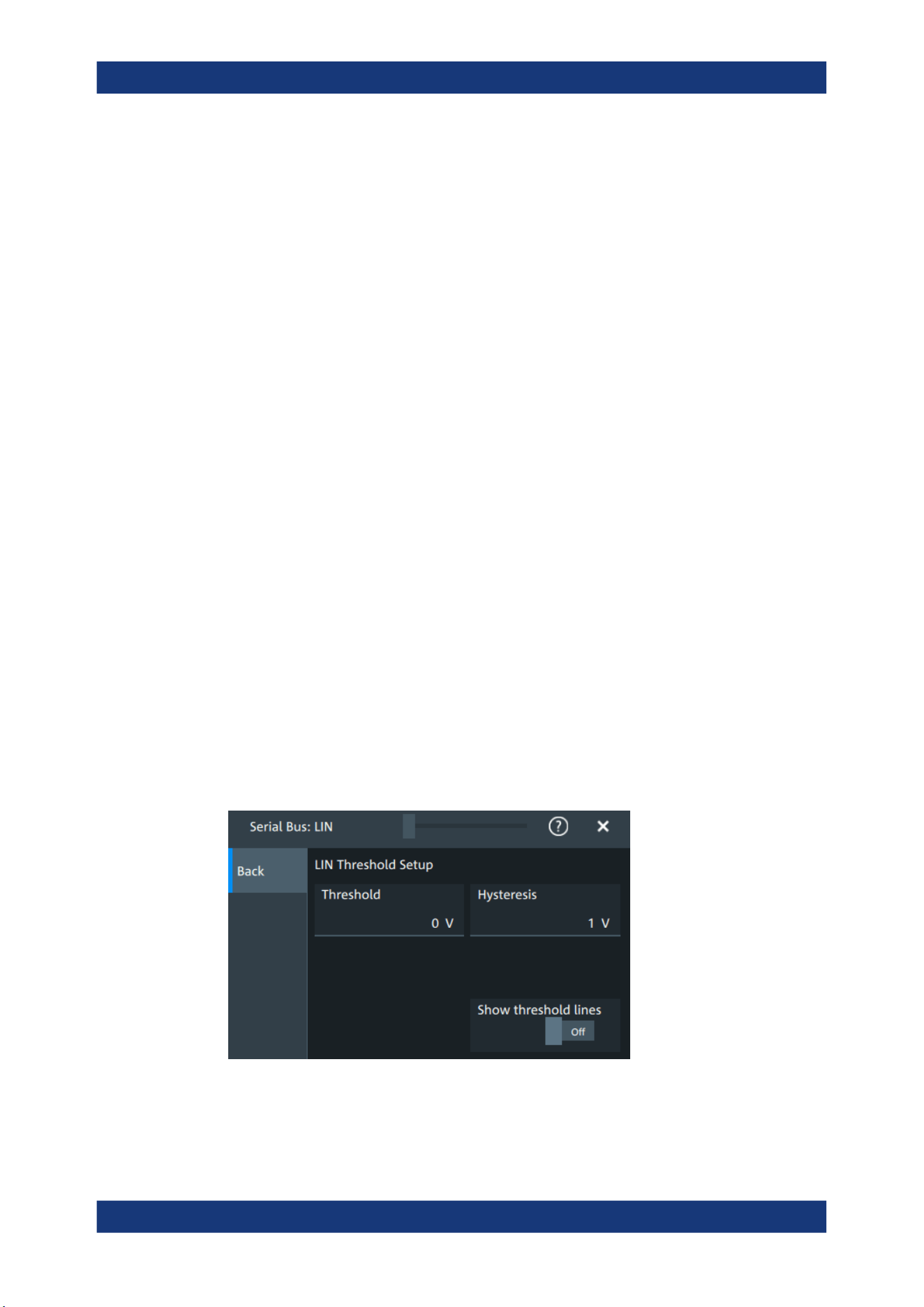
Protocol analysis
R&S
®
MXO 5 Series
367User Manual 1802.3369.02 ─ 02
LIN standard
Selects the version of the LIN standard that is used in the DUT. The setting mainly
defines the checksum version used during decoding.
The most common version is LIN v.2.x. For mixed networks, or if the standard is
unknown, set the LIN standard to "Auto".
Remote command:
SBUS<sb>:LIN:STANdard on page 735
Data
Sets the source waveform of the data line.
Remote command:
SBUS<sb>:LIN:DATA:SOURce on page 734
Polarity
Defines the idle state of the bus. The idle state is the recessive state and corresponds
to a logic high.
Remote command:
SBUS<sb>:LIN:POLarity on page 734
Bit rate
Sets the number of transmitted bits per second. The maximum bit rate for LIN is 20
kbit/s.
If the LIN standard is "J2602", the bit rate is 10.417 kbit/s and cannot be changed.
Remote command:
SBUS<sb>:LIN:BITRate on page 733
Threshold
Press "Set thresholds", to open the "Threshold setup" dialog.
Enter the value directly in the field of the threshold setup dialog.
Additional to the threshold, you can also set a hysteresis.
Remote command:
SBUS<sb>:LIN:DATA:THReshold on page 734
SBUS<sb>:LIN:DATA:HYSTeresis on page 734
LIN (option R&S
MXO5-K520)
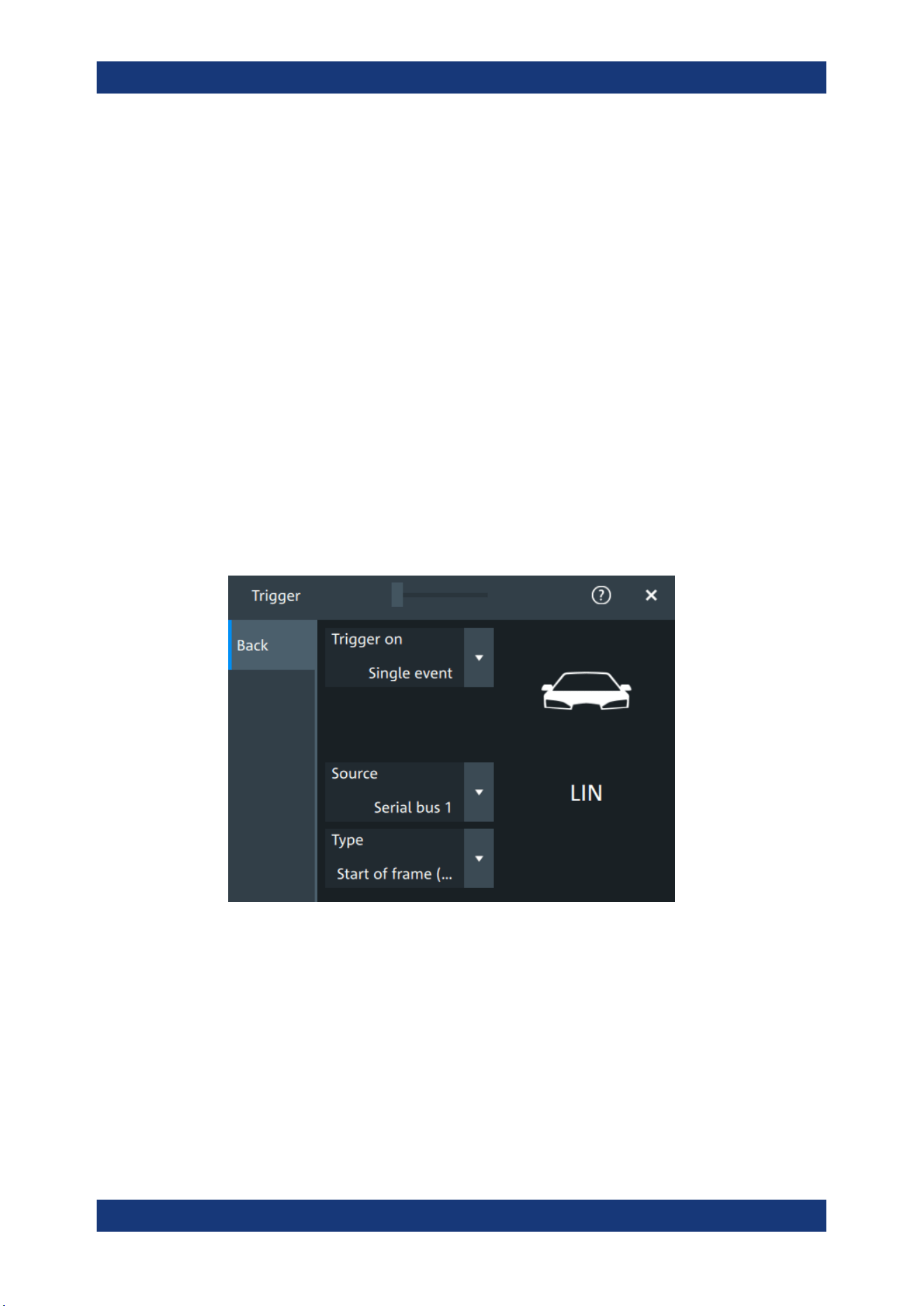
Protocol analysis
R&S
®
MXO 5 Series
368User Manual 1802.3369.02 ─ 02
Show threshold lines ← Threshold
If enabled, the threshold lines are displayed in the diagram.
The label of the threshold line is set according to the signal that it is referring to.
Remote command:
SBUS<m>:THReshold on page 646
13.6.1.2 Display settings
For details about the display settings, see Chapter 13.1.3, "Display", on page 288.
13.6.1.3 Shortcuts
For details about the available shortcuts, see Chapter 13.1.6, "Shortcuts",
on page 290.
13.6.2 LIN trigger settings
Access: [Apps] > "Protocol" > "LIN" > "Shortcuts" > "Setup trigger".
Type
Selects the trigger type for LIN analysis.
Some trigger types have additional settings that can be defined. In this case, the "Set
details" button appears next to "Type" the function. Open it for a detailed definition of
the trigger conditions.
"Start of frame
(Sync)"
Triggers on the stop bit of the sync field.
LIN (option R&S MXO5-K520)
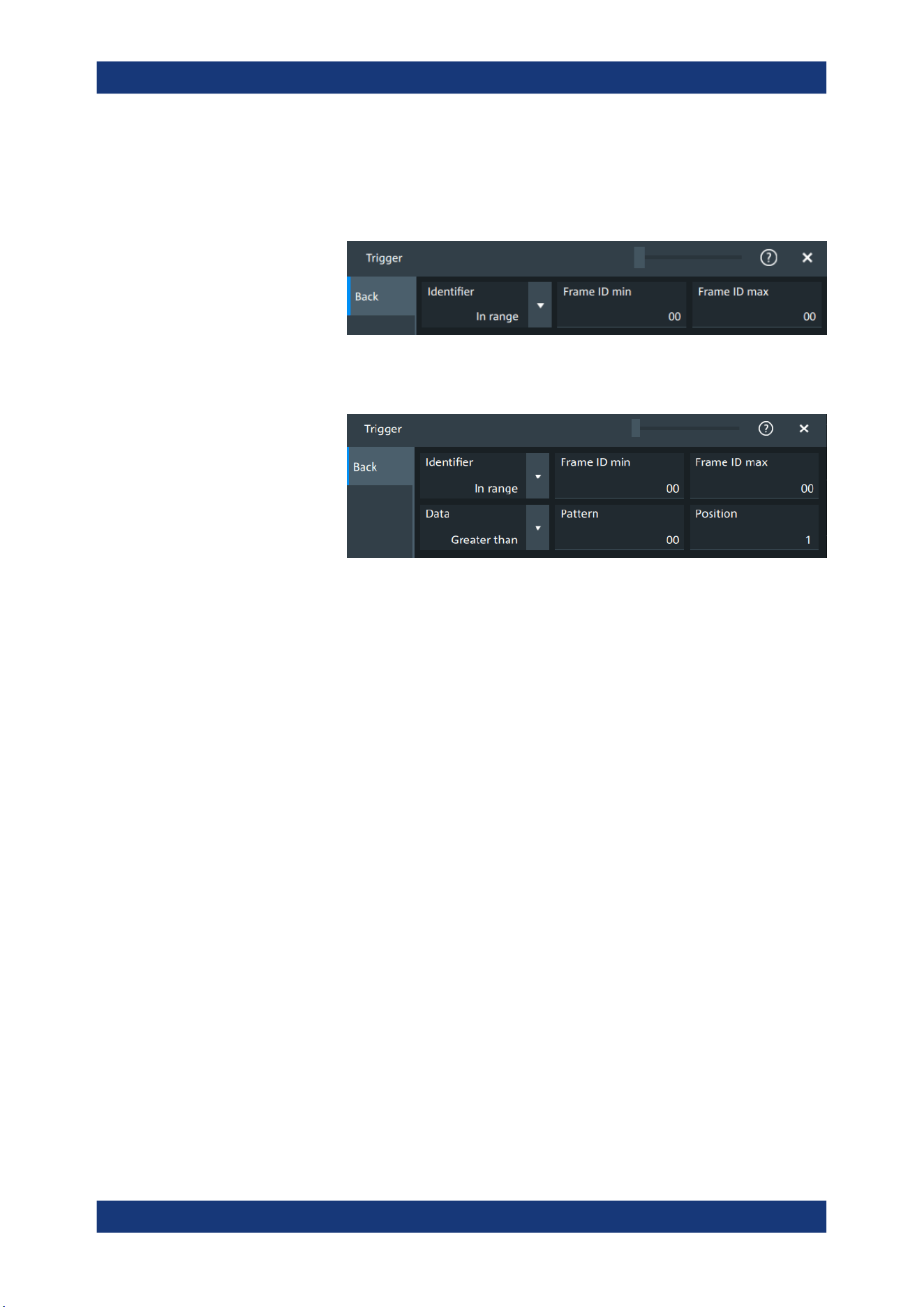
Protocol analysis
R&S
®
MXO 5 Series
369User Manual 1802.3369.02 ─ 02
"Identifier"
Sets the trigger to one specific identifier or an identifier range. Enter
only the 6-bit identifier without parity bits, not the protected identifier.
Description of trigger type specific settings: Identifier setup: Condi-
tion, Frame ID min, Frame ID max.
"Identifier +
Data"
Sets the trigger to a combination of identifier and data condition. The
instrument triggers at the end of the last byte of the specified data
pattern.
The identifier conditions are the same as for the "Identifier" trigger
type, see Identifier setup: Condition, Frame ID min, Frame ID max.
Data conditions are set with Data setup: Condition, Pattern, Position.
"Wake-up
frame"
Triggers after a wake-up frame.
"Error condi-
tion"
Identifies various errors in the frame, see Error conditions.
Remote command:
TRIGger:LIN:TYPE on page 736
Identifier setup: Condition, Frame ID min, Frame ID max
The identifier setup consists of the condition and one or two identifier pattern.
Condition
Sets the comparison condition to a specific value or a range.
"Frame ID min"
Defines the bit pattern of the identifier. Enter only the 6-bit identifier
without parity bits, not the protected identifier.
"Frame ID
max"
Sets the maximum value of a range for "Condition" = "In range"/"Out
of range".
Remote command:
TRIGger:LIN:IMIN on page 738
TRIGger:LIN:IMAX on page 738
TRIGger:LIN:ICONdition on page 737
Data setup: Condition, Pattern, Position
The data setup consists of the transfer direction, the number of bytes, the condition,
and one data pattern.
LIN (option R&S
MXO5-K520)
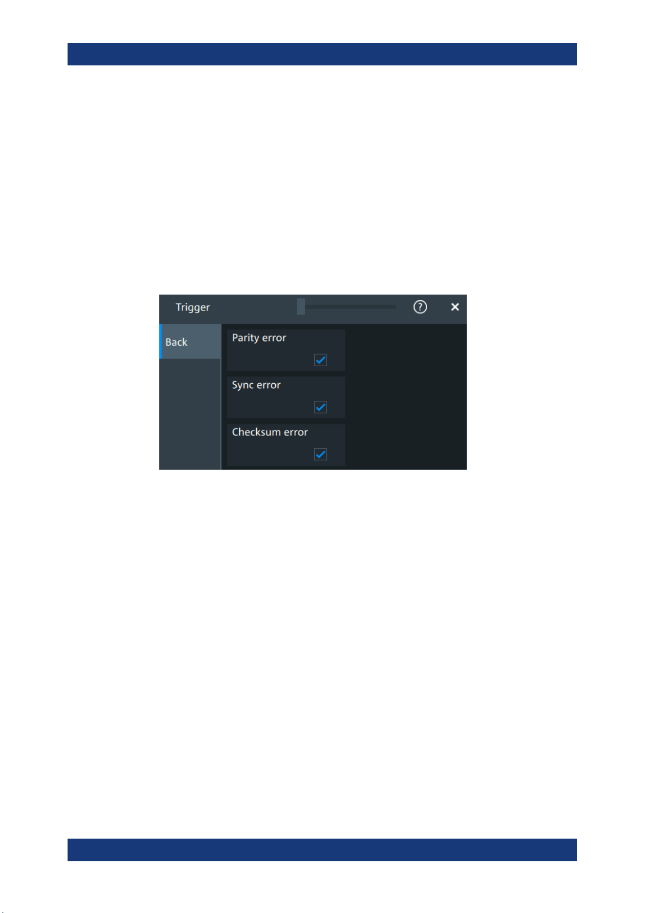
Protocol analysis
R&S
®
MXO 5 Series
370User Manual 1802.3369.02 ─ 02
Condition
Sets the operator to define a specific data pattern ("Equal" or "Not
equal") or a range smaller or bigger than a specific pattern.
"Pattern"
Defines the data pattern.
"Position"
Sets the number of data events that are ignored, before trigger condi-
tion check of the data starts.
Remote command:
TRIGger:LIN:DCONdition on page 737
TRIGger:LIN:DMIN on page 737
TRIGger:LIN:DPOSition on page 737
Error conditions
Triggers if one or more of the following errors occur.
"Parity error"
Parity bits are the bits 6 and 7 of the identifier. They verify the correct
transmission of the identifier.
"Sync error"
Synchronization error.
"Checksum
error"
The checksum verifies the correct data transmission. It is the last byte
of the frame response. The checksum includes not only the data but
also the protected identifier (PID).
Remote command:
TRIGger:LIN:IPERror on page 738
TRIGger:LIN:SYERror on page 738
TRIGger:LIN:CHKSerror on page 736
13.6.3 LIN filter
Access: [Apps] key > "Protocol" tab > "LIN" > "Filter" tab
LIN (option R&S
MXO5-K520)
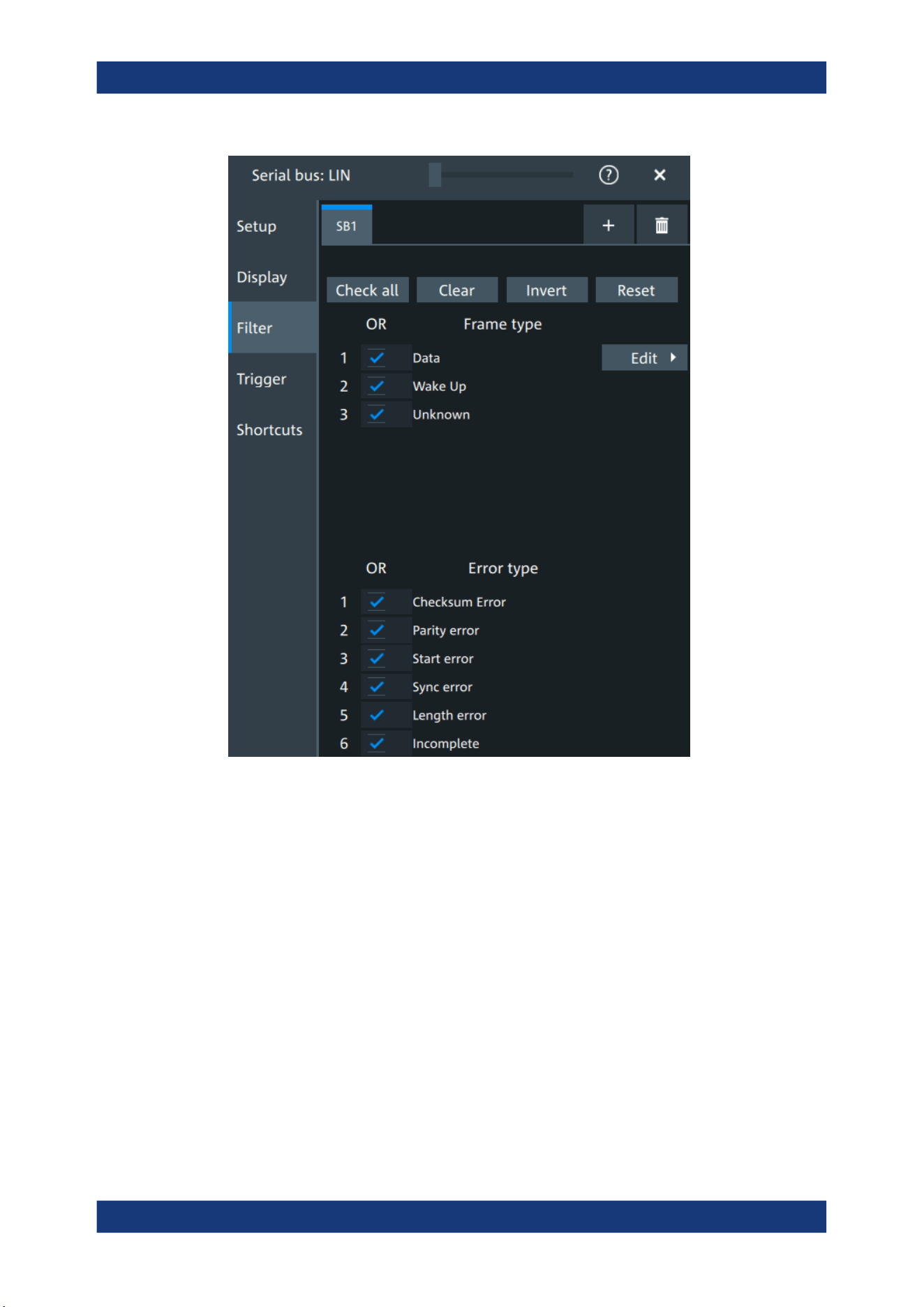
Protocol analysis
R&S
®
MXO 5 Series
371User Manual 1802.3369.02 ─ 02
In the "Filter" tab, you can define the settings to display only the frames that match the
selected filter conditions.
Check all, Clear, Invert, Reset
The following settings help you select the frames and errors you want to filter for. Only
the frames and error types that match the selected filter conditions are displayed.
"Check all"
Enables the filter for all available frames and error types.
"Clear"
Disables the filter for all available frames and error types.
"Invert"
Inverts the current state of the frame and error types: all frames and
error types that were enabled are disabled and vice versa.
"Reset"
Resets the state of the selected frames and error types.
Frame type
Selects the frame type that you want to display. You can filter all enabled frame types
simultaneously.
For each frame type, you can also specify conditions for the value of the fields in the
"Edit" dialog.
LIN (option R&S
MXO5-K520)
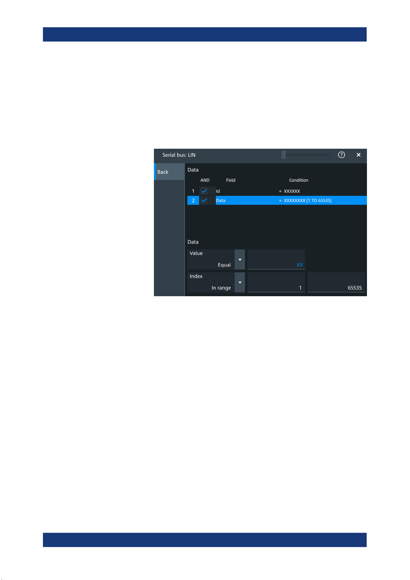
Protocol analysis
R&S
®
MXO 5 Series
372User Manual 1802.3369.02 ─ 02
Available frames are "Data", "Wake" and "Unknown".
Remote command:
SBUS<sb>:LIN:FILTer:FRENable on page 742
SBUS<sb>:LIN:FILTer:FRAMe<fr>:ENABle on page 742
Edit
Opens a dialog to define the details of the selected frame.
"Field"
Enables the field type that you want to filter on for the selected frame.
The available fields are "Id" and "Data".
Remote command:
SBUS<sb>:LIN:FILTer:FIENable on page 741
SBUS<sb>:LIN:FILTer:FRAMe<fr>:FLD<fl>:ENABle
on page 741
"Condition"
Displays the value condition for the selected field.
Remote command:
SBUS<sb>:LIN:FILTer:BIT on page 739
SBUS<sb>:LIN:FILTer:FRAMe<fr>:FLD<fl>:BIT on page 739
"Data"
The data setup consists of a comparison condition and one or two
data patterns.
Remote command:
SBUS<sb>:LIN:FILTer:DMAX on page 740
SBUS<sb>:LIN:FILTer:FRAMe<fr>:FLD<fl>:DMAX
on page 740
SBUS<sb>:LIN:FILTer:DMIN on page 740
SBUS<sb>:LIN:FILTer:FRAMe<fr>:FLD<fl>:DMIN
on page 740
SBUS<sb>:LIN:FILTer:DOPerator on page 740
SBUS<sb>:LIN:FILTer:FRAMe<fr>:FLD<fl>:DOPerator
on page 740
LIN (option R&S MXO5-K520)

Protocol analysis
R&S
®
MXO 5 Series
373User Manual 1802.3369.02 ─ 02
"Index"
The index setup consists of a comparison condition and one or two
index values.
Remote command:
SBUS<sb>:LIN:FILTer:IMAX on page 742
SBUS<sb>:LIN:FILTer:FRAMe<fr>:FLD<fl>:IMAX
on page 742
SBUS<sb>:LIN:FILTer:IMIN on page 742
SBUS<sb>:LIN:FILTer:FRAMe<fr>:FLD<fl>:IMIN
on page 742
SBUS<sb>:LIN:FILTer:IOPerator on page 743
SBUS<sb>:LIN:FILTer:FRAMe<fr>:FLD<fl>:IOPerator
on page 743
Error type
Enables filtering on the selected error type.
The available errors are "Checksum error", "Parity error","Start error", "Sync error",
"Length error" and "Incomplete".
Remote command:
SBUS<sb>:LIN:FILTer:ERENable on page 741
SBUS<sb>:LIN:FILTer:ERRor<n>:ENABle on page 741
13.6.4 LIN decode results
When the configuration of the serial bus is complete, the signal can be decoded:
1. Open the "Serial Bus" dialog for the respective bus.
2. In the "Setup" tab, enable "State".
3. In the "Display" tab, enable "Show decode table".
For a description of the display settings, see also Chapter 13.1.3, "Display",
on page 288.
The instrument captures and decodes the signal according to the standard definition
and the configuration settings.
The color-coding of the various protocol sections and errors simplifies the interpretation
of the visual display. The decode information condenses or expands, depending on the
horizontal scale. Various data formats are available to show the result values.
LIN (option R&S MXO5-K520)
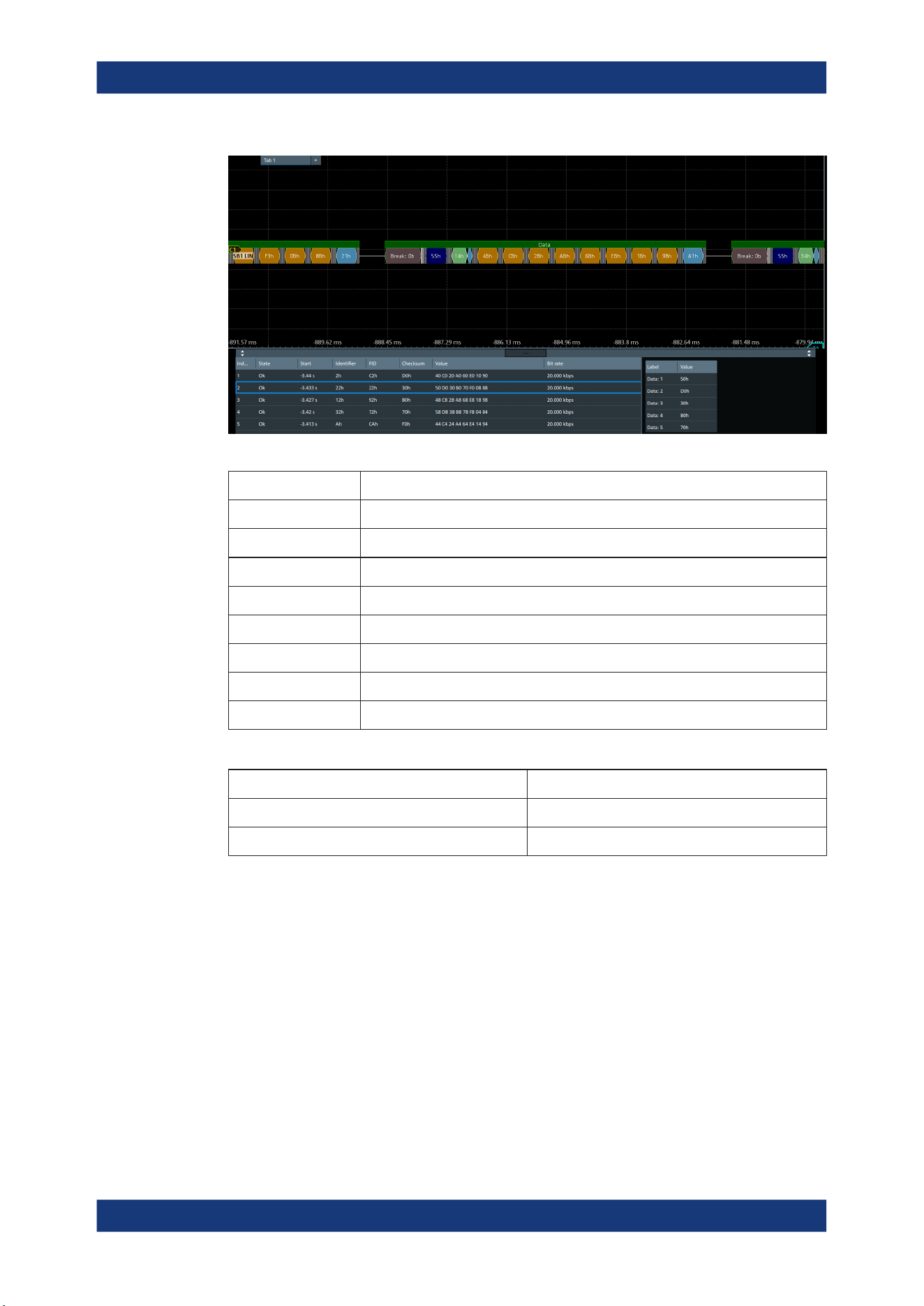
Protocol analysis
R&S
®
MXO 5 Series
374User Manual 1802.3369.02 ─ 02
Table 13-9: Content of the Decode results table
Column Description
Index Index of the decoded frame
State Overall state of the frame
Start Time of frame start
Identifier Identifier value
PID Protected identifier
Checksum Checksum value
Values Value of the data bytes. The data format is selected below the table.
Bit rate Value of the bit rate
Table 13-10: Content of the Details frame table
Column Description
Label State of the field
Value Value of the field
Data format
You can select various data formats for the values displayed in the decode table and in
the combs of the decoded signal.
Remote command:
●
SBUS<sb>:FORMat on page 645
Export of decode results
1. In the protocol "Shortcuts" tab, press "Export results".
The "Export results" dialog opens.
For details, see Chapter 13.1.7, "Export protocol results", on page 291.
LIN (option R&S
MXO5-K520)
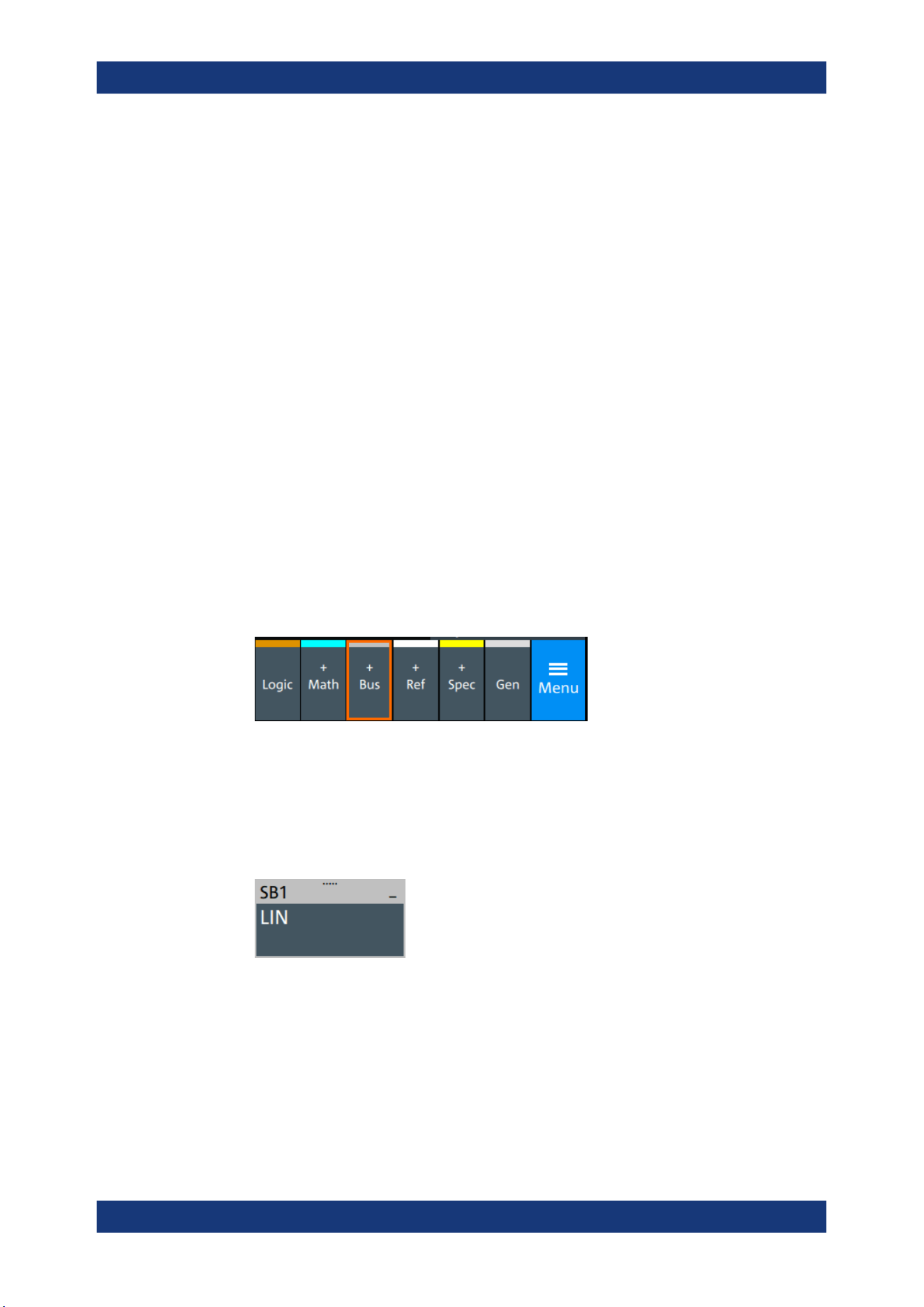
Protocol analysis
R&S
®
MXO 5 Series
375User Manual 1802.3369.02 ─ 02
2. Select the details that you want to export and the file format.
3. Tap "Save as".
4. Key in a name and select the file format.
Remote commands
Remote commands to retrieve decode results are described in Chapter 17.16.6, "LIN
(option R&S MXO5-K520)", on page 733.
13.6.5 Performing LIN decoding
This chapter explains step by step how to configure and decode the LIN bus.
13.6.5.1 Configuring LIN signals
For configuration, assign the lines to the input channels, and define the active states
and the logical thresholds.
For details on configuration settings, see Chapter 13.6.1, "LIN configuration",
on page 366.
1. Tap the "Bus" activator in the bottom right of the screen.
2. Select the tab of the bus that you want to set up, for example "SB1".
3. Tap the "Protocol type" button. Select the protocol: LIN.
4. Tap on "State" to enable the decoding.
An SPI shortcut appears at the bottom left of the screen. Tap on the shortcut for a
quick access to the "LIN" dialog settings.
5. Select the "LIN standard".
6. Select the correct channel for "Data".
7. Set the "Bit rate".
8. Check that the signals are on the screen.
If not try adjusting the vertical and horizontal settings.
9. Set the logical thresholds:
LIN (option R&S
MXO5-K520)

Protocol analysis
R&S
®
MXO 5 Series
376User Manual 1802.3369.02 ─ 02
a) Tap "Threshold setup". The threshold dialog opens.
b) For each wire, set the threshold value. A typical value is 3.5 V.
c) If necessary, set the hysteresis value.
d) Optionally, tap on "Show threshold lines".
13.6.5.2 Triggering on LIN
Prerequisites: A bus is configured for the LIN signal to be analyzed. See Chap-
ter 13.6.5.1, "Configuring LIN signals", on page 375.
1. Open "Menu" > "Trigger".
2. Set "Trigger on" to "Single event".
3. Ensure that the "Source" is set to the configured serial bus, e.g. "Serial bus 1".
4. Select the "Type".
5. Define additional settings for more complex trigger types: "Identifier", "Identifier
+Data" .
a) Tap on "Set details".
b) Set the "Identifier" condition or an identifier range.
c) Set the "Data" condition or a data range.
13.6.5.3 Exporting decode results
Once a decode has been completed, you can export the decode results of the
Prerequisites: A bus is configured for the LIN and decoded.
1. Tap on the "LIN" shortcut.
2. Tap on the "Shortcuts" tab.
3. Tap "Export results".
4. If necessary, enable "Include details".
5. If necessary, enable "Include timing".
6. Select the "File type".
An export file is saved in the selected directory.
The LIN export file contains the following fields:
●
A list of all decoded frames:
– Index
– Start
– Stop
– State
– Identifier
LIN (option R&S
MXO5-K520)

Protocol analysis
R&S
®
MXO 5 Series
377User Manual 1802.3369.02 ─ 02
– PID
– Checksum
– Bit rate
●
The details frames include the following fields:
– Index
– State
– Value
Example of LIN export file
Index,Start,Stop,State,Identifier,PID,Checksum,Bit rate
1,-3.44,-3.43375,'OK',02h,C2h,D0h,20000
2,-3.43325,-3.427,'OK',22h,22h,30h,20000
3,-3.4265,-3.42025,'OK',12h,92h,B0h,20000
4,-3.41975,-3.4135,'OK',32h,72h,70h,20000
5,-3.413,-3.40675,'OK',0Ah,CAh,F0h,20000
Details frame 1
Index,State,Value
1,'OK',40h
2,'OK',C0h
3,'OK',20h
4,'OK',A0h
5,'OK',60h
6,'OK',E0h
7,'OK',10h
8,'OK',90h
Details frame 2
Index,State,Value
1,'OK',50h
2,'OK',D0h
3,'OK',30h
4,'OK',B0h
5,'OK',70h
6,'OK',F0h
7,'OK',08h
8,'OK',88h
LIN (option R&S MXO5-K520)

Mixed signal option (MSO, R&S MXO5-B1)
R&S
®
MXO 5 Series
378User Manual 1802.3369.02 ─ 02
14 Mixed signal option (MSO, R&S MXO5-B1)
The Mixed Signal Option R&S MXO5-B1 adds logic analyzer functions to the classical
oscilloscope functions. Using the MSO option, you can analyze and debug embedded
systems with mixed-signal designs that use analog signals and correlated digital sig-
nals simultaneously.
The Mixed Signal Option provides 16 digital channels grouped in two logic probes
(pods) with 8 channels each. The instrument ensures that analog and digital wave-
forms are time-aligned and synchronized so that critical timing interactions between
analog and digital signals can be displayed and tested. The automatic alignment com-
pensates the skew between the probe connectors of the analog channels and the
probe boxes of the digital channels.
14.1 Logic configuration
Access: "Menu" > "Logic" > "Setup" tab
Digital channels can be displayed individually, and they can be grouped and displayed
as a logic group. You can configure and enable up to 4 logic groups. Each digital chan-
nel can be assigned to one active logic only, the instrument disables conflicting buses
automatically.
For clocked buses, you can display the decoded data in a result box.
If you have configured several logic groups and you want to modify the settings, make
sure that the tab of the correct logic is selected. Disable the logic before you change
the settings.
14.1.1 Setup
Access: "Menu" > "Logic" > "Setup" tab
Logic configuration
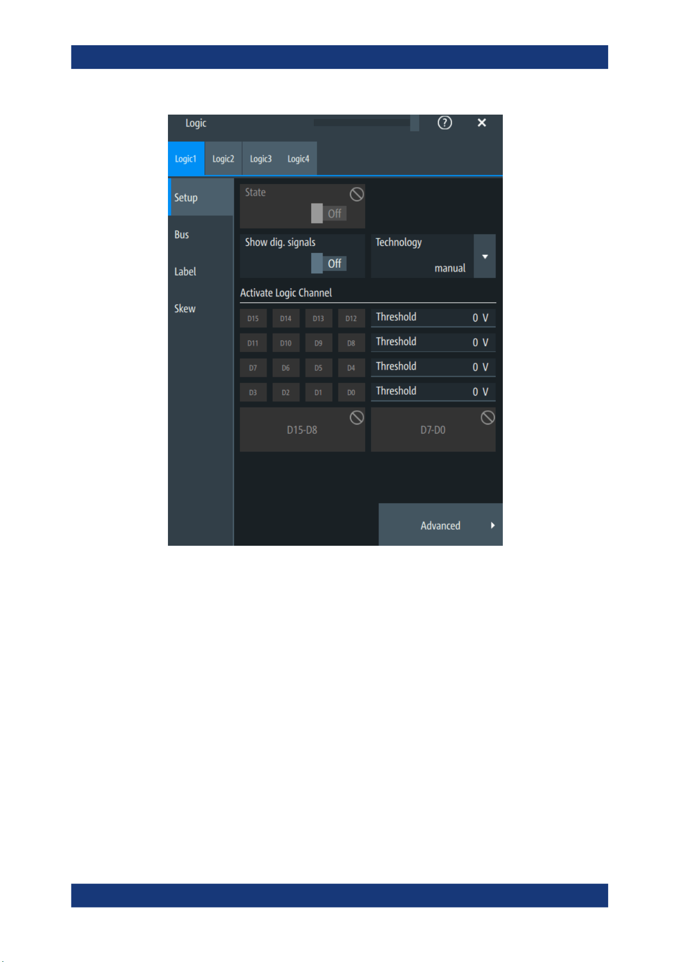
Mixed signal option (MSO, R&S MXO5-B1)
R&S
®
MXO 5 Series
379User Manual 1802.3369.02 ─ 02
State
Enables the selected logic group. The corresponding signal icon appears on the signal
bar.
If another active bus already uses the same digital channel, the instrument disables the
other bus and shows a message.
Remote command:
PBUS<pb>:STATe on page 757
Show dig. signals
If enabled, the selected digital channels are shown in the diagram. Each channel is dis-
played as a logic signal.
Remote command:
PBUS<pb>:DISPlay:SHDI on page 755
Logic configuration
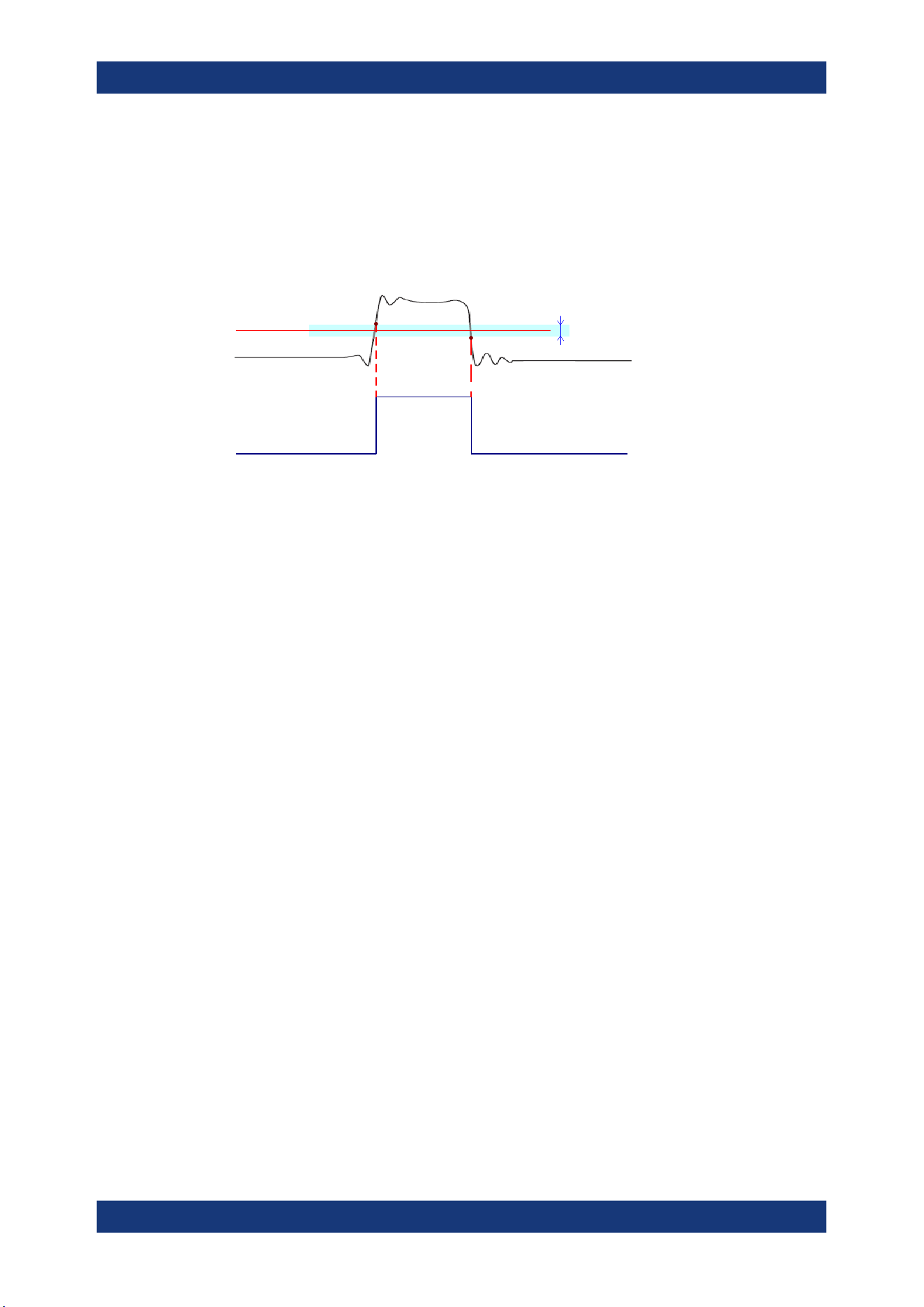
Mixed signal option (MSO, R&S MXO5-B1)
R&S
®
MXO 5 Series
380User Manual 1802.3369.02 ─ 02
Technology,Threshold
Sets the logical threshold. For each sample, the instrument compares the input voltage
with the threshold value. If the input voltage is above the threshold, the signal state "1"
is stored. Otherwise, the signal state "0" is stored if the input voltage is below the
threshold.
To avoid the change of signal states due to noise, a hysteresis is considered.
Threshold
Logic 0 Logic 1 Logic 0
Hysteresis
By default, same threshold and hysteresis value are used for all digital channels and all
logic buses: "Couple thresholds" is enabled.
You can also set different thresholds for the individual channel groups. As long as the
buses are disabled, you can set different thresholds for each bus. Active buses use the
same threshold and hysteresis values, the settings of the last activated bus take effect.
The range of threshold levels and the minimum voltage swing is given in the data
sheet.
"Threshold"
Enter the value directly in the field.
"Technology"
Selects the threshold voltage for various types of integrated circuits
from a list and applies it to all digital channels. The value is set to
"Manual" if a user-defined threshold was entered directly.
Remote command:
PBUS<pb>:TECHnology on page 757
PBUS<pb>:THReshold<n> on page 758
Advanced
Opens a dialog for advanced threshold and hysteresis settings. You can define them
additional to the "Threshold" and "Technology".
Level coupling ← Advanced
Sets the threshold and the hysteresis for all digital channels and all buses to the same
value.
Remote command:
PBUS<pb>:THCoupling on page 758
Hysteresis ← Advanced
Defines the size of the hysteresis for the respective channels.
"Normal"
The instrument sets a small value suitable for the signal and its set-
tings. Use this setting for clean signals.
"Maximum"
The instrument sets the maximum value that is possible and useful
for the signal and its settings. Use this setting for noisy signals.
Logic configuration
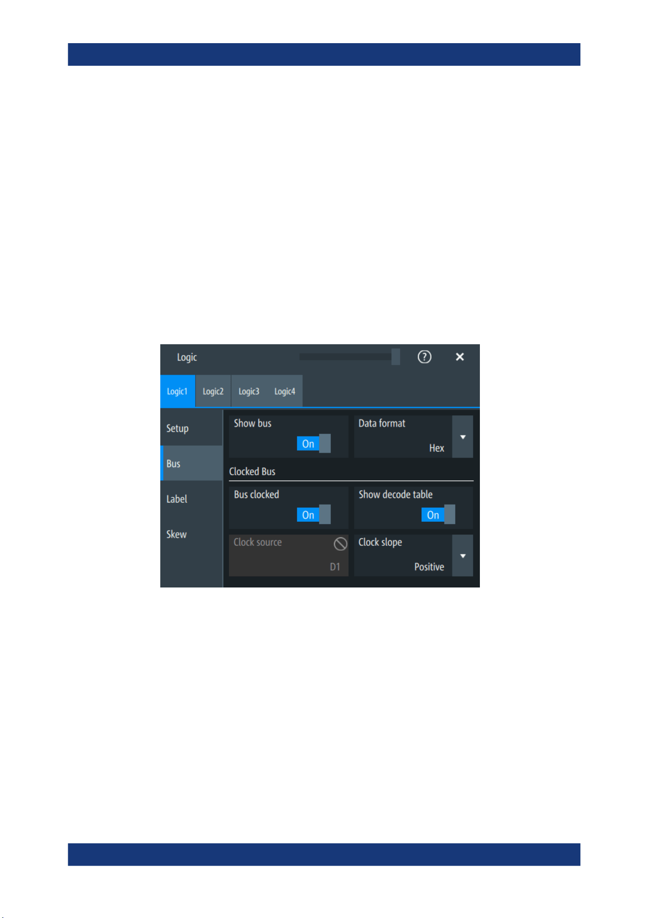
Mixed signal option (MSO, R&S MXO5-B1)
R&S
®
MXO 5 Series
381User Manual 1802.3369.02 ─ 02
"Robust"
Sets different hysteresis values for falling and rising edges to avoid
an undefined state of the trigger system. Use this setting for very
noisy signals.
Remote command:
PBUS<pb>:HYSTeresis<n> on page 756
Active logic channel
Selects the state of the respective bus channel.
Enable/Disable D7-D0,D15-D8
The buttons select or deselect all digital channels of a pod at once.
14.1.2 Bus
Access: "Menu" > "Logic" > "Bus" tab
Show bus
If enabled, the resulting bus signal and bus values are displayed in the diagram.
Remote command:
PBUS<pb>:DISPlay:SHBU on page 755
Data format
Sets the data format of bus values, which are displayed in the decode table and on the
comb bus display.
Available formats are: Hex, octal, binary, ASCII, string, signed, unsigned, symbolic, and
auto.
Signed and Unsigned are integer data types with maximum 16-bit length. Unsigned is
used for positive integers. Signed is used for positive and negative integers.
Logic configuration

Mixed signal option (MSO, R&S MXO5-B1)
R&S
®
MXO 5 Series
382User Manual 1802.3369.02 ─ 02
If the target file format is BIN, you can save only signed and unsigned binary data. The
data format "Signed" writes signed data; all other formats are saved as unsigned
binary data.
Remote command:
PBUS<pb>:DATA:FORMat on page 760
PBUS<pb>:DATA:HEADer? on page 760
PBUS<pb>:DATA[:VALues]? on page 761
Clocked bus
If a bus is a clocked bus, one of the digital channels serves as clock of the bus.
For an unclocked bus, the logical state of the bus is determined for each sample. For a
clocked bus, the logical state is determined only at the specified clock edges.
Bus clocked ← Clocked bus
Enable this option for a clocked bus.
Remote command:
PBUS<pb>:CLON on page 754
Show decode table ← Clocked bus
If enabled, a results box opens with decoded values of the bus signal and its time.
Each clock edge corresponds to one row in the table.
The decode table is only available for clocked buses to check the data words.
Clock source ← Clocked bus
Selects the digital channel used as clock.
Remote command:
PBUS<pb>:CLOCk on page 753
Clock slope ← Clocked bus
Selects the slope of the clock signal at which all digital channels of the bus are ana-
lyzed.
Remote command:
PBUS<pb>:CLSLope on page 754
14.1.3 Label settings
Access: "Menu" > "Logic" > "Label" tab
Logic configuration
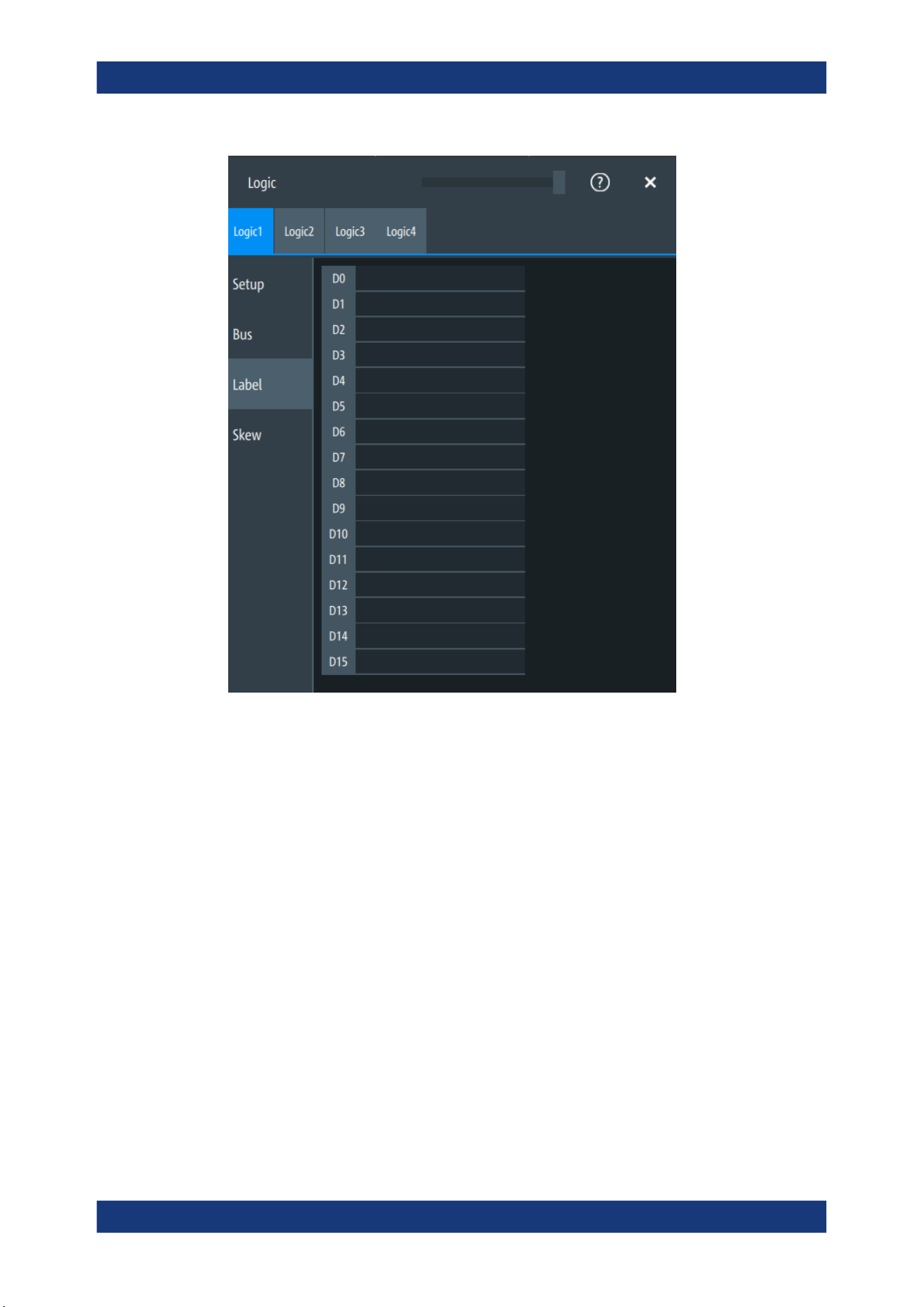
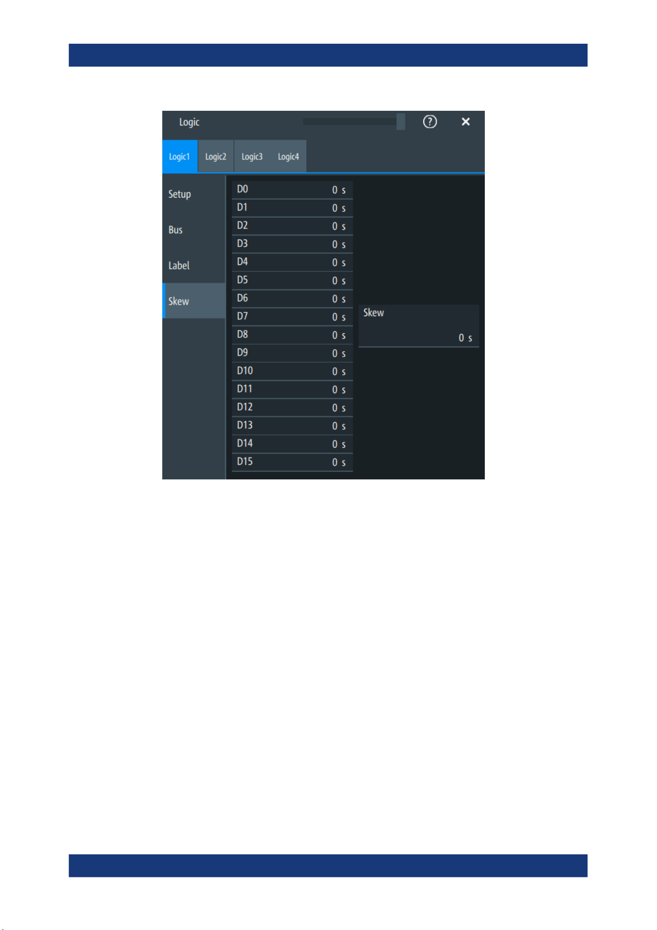
Mixed signal option (MSO, R&S MXO5-B1)
R&S
®
MXO 5 Series
384User Manual 1802.3369.02 ─ 02
D0-D15
Sets an individual delay for each digital channel to time-align it with other digital chan-
nels.
The skew value compensates delays that are known from the circuit specifics or
caused by the different length of cables. The skew between the probe boxes of the dig-
ital channels and the probe connectors of the analog channels is automatically aligned
by the instrument.
Remote command:
PBUS<pb>:BIT<n>:SKEW on page 752
Skew
Sets a general delay for all digital channels.
Remote command:
PBUS<pb>:SKEW on page 757
14.2 Display
Each logic group is shown in a separate diagram, and the diagrams can be minimized
and arranged as usual.
Display
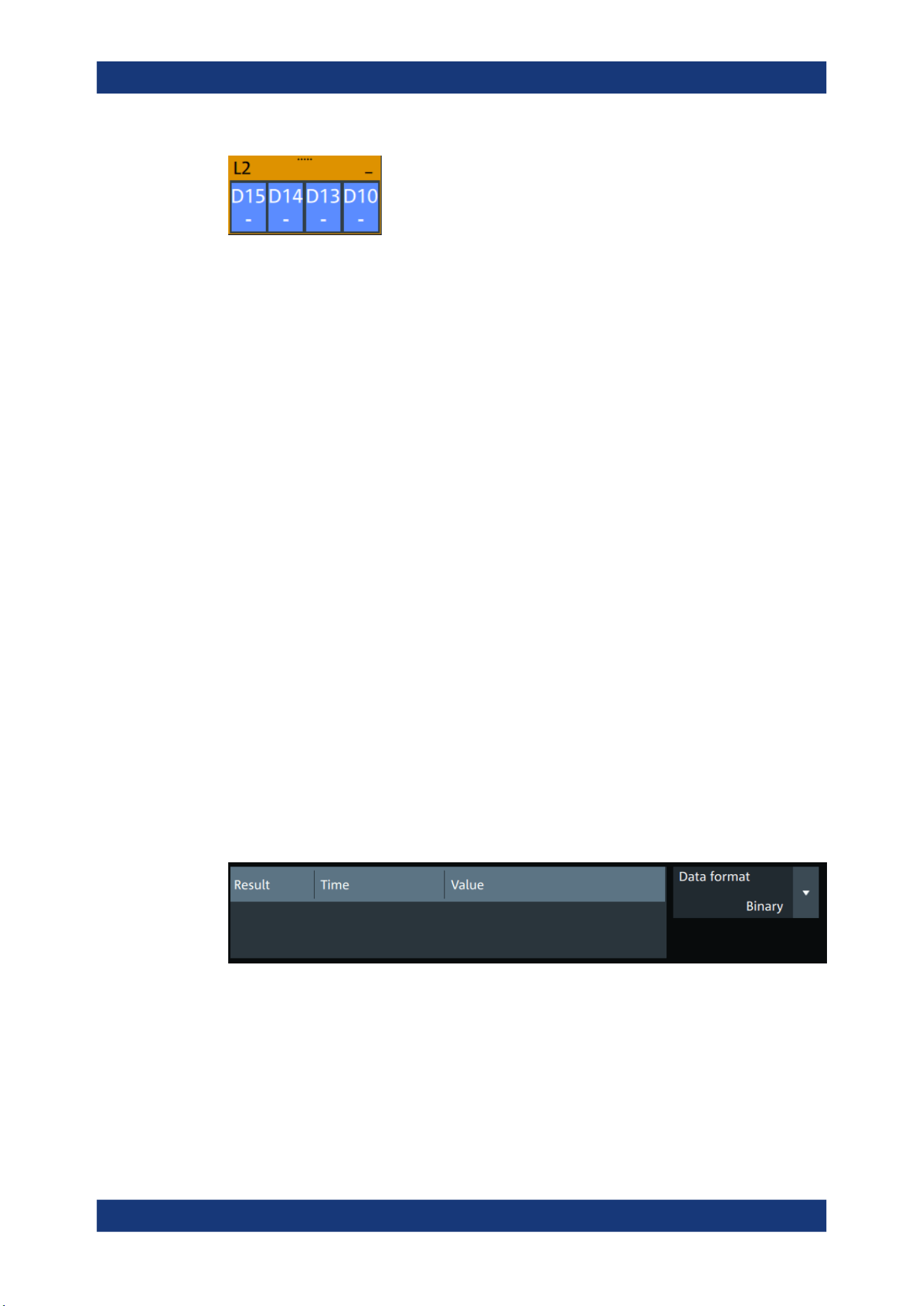
Mixed signal option (MSO, R&S MXO5-B1)
R&S
®
MXO 5 Series
385User Manual 1802.3369.02 ─ 02
You can adjust the display of the logic bus signals and the individual digital channels to
optimize the analysis of bus data:
●
Show the digital channels which are assigned to the bus, drag them to the optimal
position, and scale them.
●
Adjust size and position of the logic signal: Therefore, tap the Lx signal or the sig-
nal icon, and use the [Position] and [Scale] knobs.
●
Adjust size and position of all active digital channels: Therefore, tap one of the Dx
signals, and use the [Position] and [Scale] knobs.
●
Show the result table of the decoded clocked bus signal.
Remote commands:
●
PBUS<pb>:DIGSignals:POSition on page 754
●
PBUS<pb>:DIGSignals:SCALe on page 755
●
PBUS<pb>:POSition on page 756
●
PBUS<pb>:SCALe on page 756
To access and analyze one or more specific acquisitions, you can use the "History" in
the common way.
Furthermore, you can zoom in digital signals and bus signal in the same way as in ana-
log waveforms.
14.2.1 Logic bus - decode table
Decoding is available for clocked buses.
The decode table shows the decoded data words of the bus signal and the corre-
sponding time. Each clock edge corresponds to one row in the table. Beside the table,
you can select the data format of the bus values.
The results can be saved to a .csv or .html file.
Display

Waveform generator (option R&S MXO5-B6)
R&S
®
MXO 5 Series
386User Manual 1802.3369.02 ─ 02
15 Waveform generator (option R&S MXO5-
B6)
The R&S MXO 5 includes a two-channel 100 MHz waveform generator which can gen-
erate a wide range of waveform and modulation types.
With each of the waveform generators, one can output simple functions, modulated
sine waveform, arbitrary waveforms and sweep waveforms. It is possible to couple and
synchronize the settings of the waveform generators.
The instrument preset does not affect the generator settings. Each generator has its
own preset ("Default setup"). When the instrument is shut down, the waveform genera-
tor settings are stored. At instrument start, these settings are restored but the genera-
tors are switched off. When a saveset of instrument settings is recalled, generators are
also switched off but the generator settings remain unchanged.
15.1 Setup of the waveform generator
Access: "Gen" signal activator > "Gen"1 or "Gen"2 > "Setup" tab.
15.1.1 General settings
The "Setup" tab provides general settings like enabling the waveform generator, and
setting that depend on the selected function type.
Setup of the waveform generator
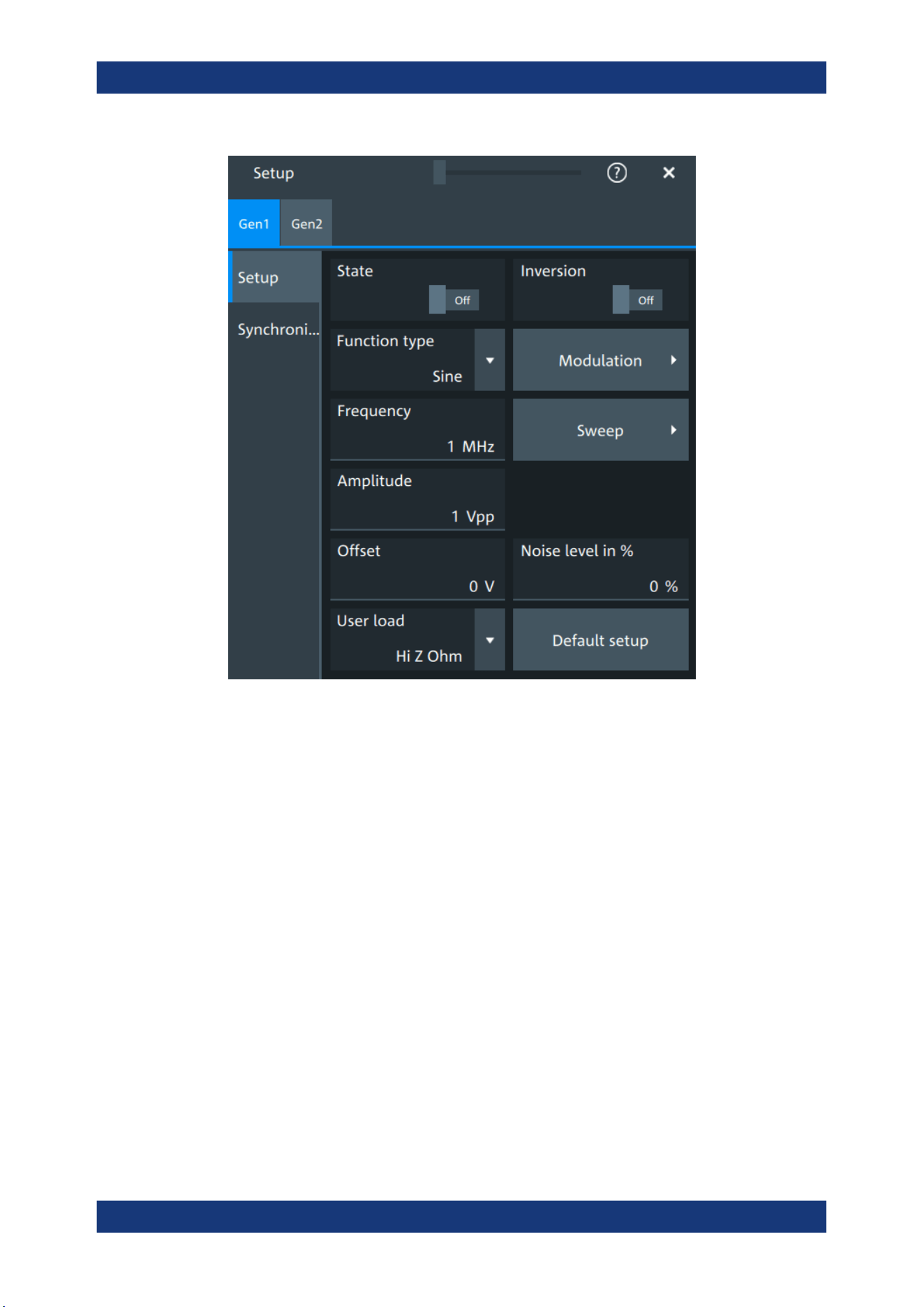
Waveform generator (option R&S MXO5-B6)
R&S
®
MXO 5 Series
387User Manual 1802.3369.02 ─ 02
State
Enables the function generator.
Remote command:
WGENerator<wg>[:ENABle] on page 766
Inversion
Inverts the waveform at the offset level.
Remote command:
WGENerator<wg>:VOLTage:INVersion on page 765
Function type
Selects the type of waveform to be generated.
For all waveforms, you can set:
●
Frequency
●
Amplitude
●
Offset
Setup of the waveform generator
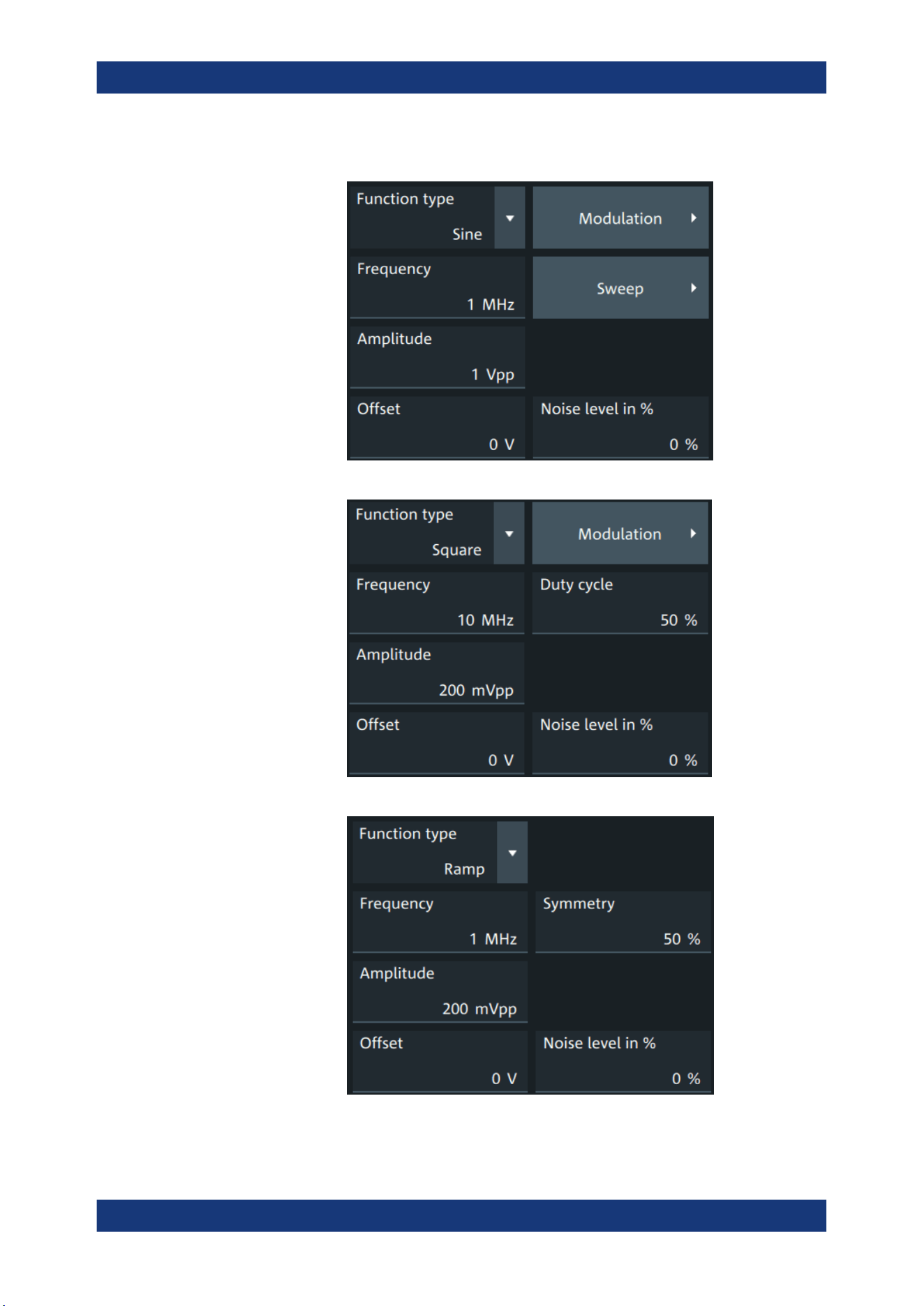
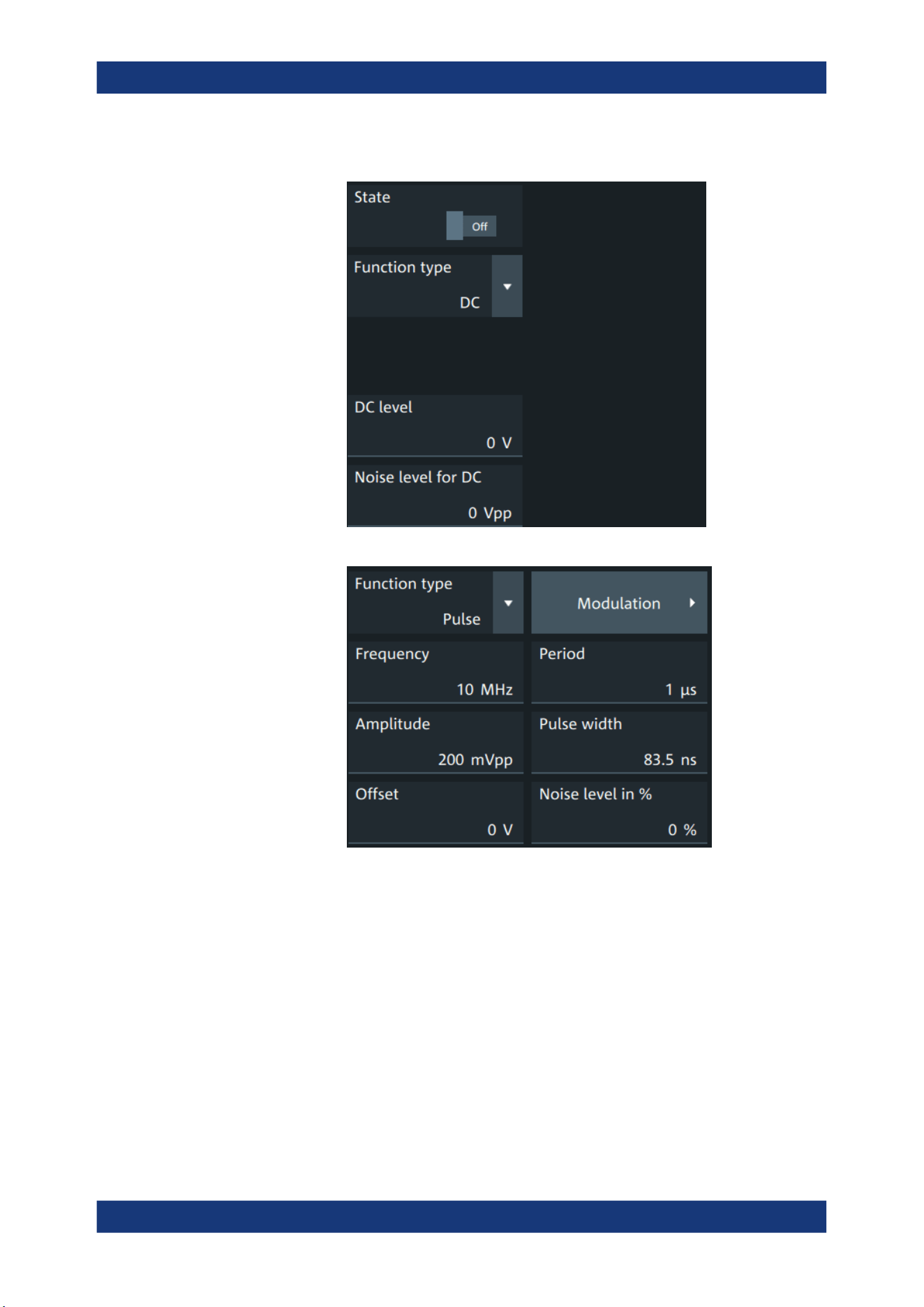
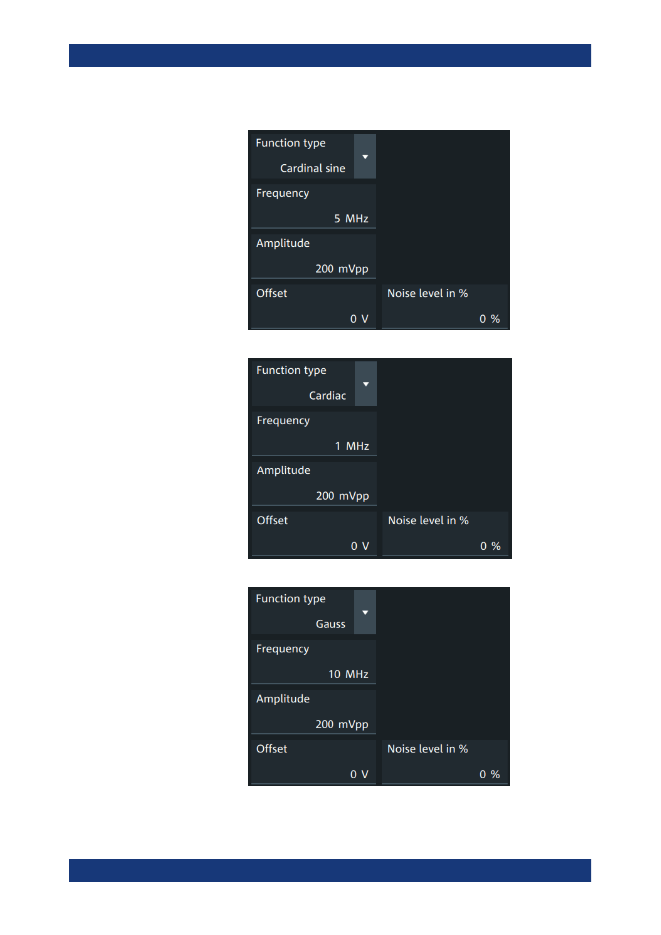
Waveform generator (option R&S MXO5-B6)
R&S
®
MXO 5 Series
390User Manual 1802.3369.02 ─ 02
"Cardinal sine"
Generates a cardinal sine wave.
"Cardiac"
Generates a cardiac signal.
"Gauss"
Generates a Gaussian signal.
Setup of the waveform generator
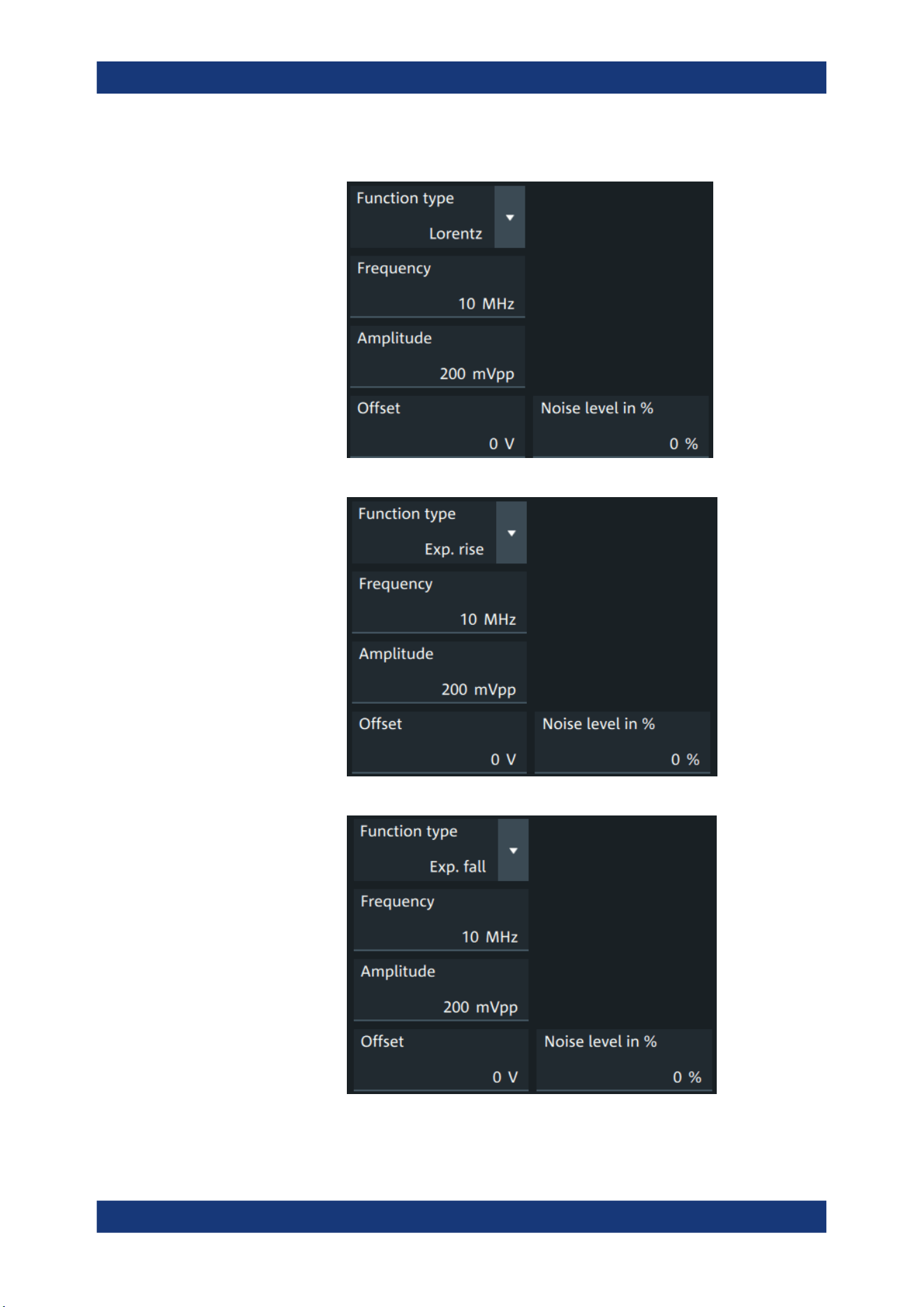
Waveform generator (option R&S MXO5-B6)
R&S
®
MXO 5 Series
391User Manual 1802.3369.02 ─ 02
"Lorentz"
Generates a Lorentz signal .
"Exp. rise"
Generates an exponential rise signal.
"Exp. fall"
Generates an exponential fall signal.
Setup of the waveform generator
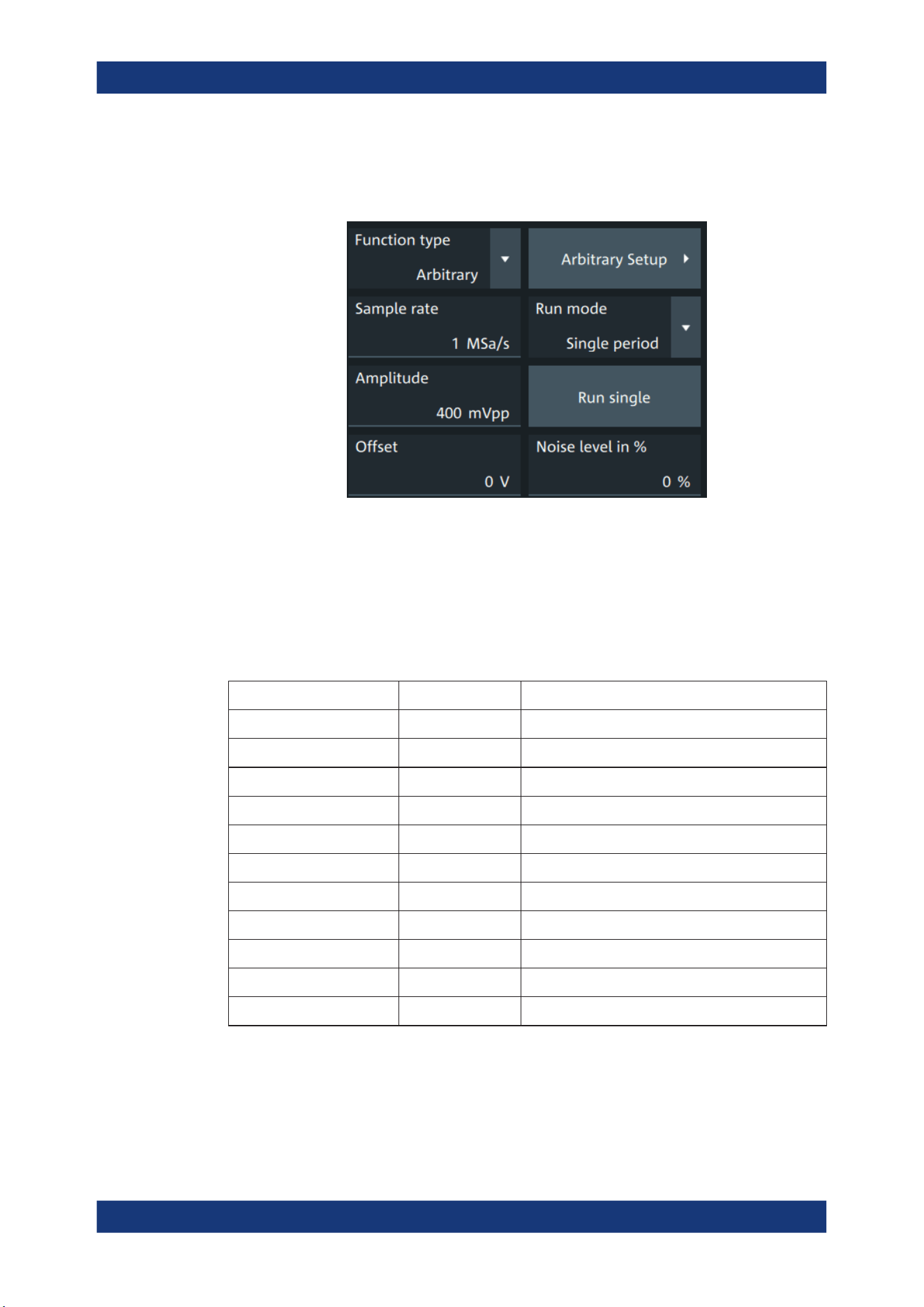
Waveform generator (option R&S MXO5-B6)
R&S
®
MXO 5 Series
392User Manual 1802.3369.02 ─ 02
"Arbitrary"
Generates an arbitrary waveform, which is copied from an existing
waveform, or loaded from file. See Chapter 15.1.4, "Arbitrary wave-
forms", on page 398.
Remote command:
WGENerator<wg>:FUNCtion[:SELect] on page 763
Frequency
Sets the frequency of the waveform.
The available frequency range depends on the selected "Function type", see Fre-
quency range of the function generator waveforms.
Table 15-1: Frequency range of the function generator waveforms
"Function type" Min frequency Max frequency
"Sine" 0.001 Hz 100 MHz
"Square" 0.001 Hz 30 MHz
"Ramp" 0.001 Hz 1 MHz
"DC" - -
"Pulse" 0.001 Hz 30 MHz
"Cardinal sine" 0.001 Hz 5 MHz
"Cardiac" 0.001 Hz 1 MHz
"Gauss" 0.001 Hz 25 MHz
"Lorentz" 0.001 Hz 10 MHz
"Exp.rise" 0.001 Hz 10 MHz
"Ep. fall" 0.001 Hz 10 MHz
Remote command:
WGENerator<wg>:FREQuency on page 762
Amplitude
Sets the amplitude of the waveform.
Setup of the waveform generator

Waveform generator (option R&S MXO5-B6)
R&S
®
MXO 5 Series
393User Manual 1802.3369.02 ─ 02
Remote command:
WGENerator<wg>:VOLTage[:VPP] on page 766
Offset
Sets the vertical offset of the generated waveform.
Remote command:
WGENerator<wg>:VOLTage:OFFSet on page 766
Arbitrary Setup
Opens a menu to configure the arbitrary waveform.
See Chapter 15.1.4, "Arbitrary waveforms", on page 398.
Sweep
Opens a menu to configure the sweep.
See Chapter 15.1.3, "Sweep settings", on page 397.
Modulation
Opens a menu to configure the modulation.
See Chapter 15.1.2, "Modulation settings", on page 394.
Noise level in %
Sets the level of the noise in percentage of the set "Amplitude" output of the signal.
Remote command:
WGENerator<wg>:MODulation:NLPCent on page 773
User load
Select the user load, the load of the DUT at its connection.
You can select either a "50Ω" or a "High-Z" (high input impedance) load.
Remote command:
WGENerator<wg>:OUTPut[:LOAD] on page 764
Symmetry
Sets the symmetry of a ramp waveform, the percentage of time the waveform is rising.
By changing the symmetry of the ramp, you can create, for example, triangular wave-
forms.
50% defines symmetric triangles. Values <50% define triangles with steeper rising
edge leaned to the left. Values >50% define triangles with steeper falling edge leaned
to the right.
Remote command:
WGENerator<wg>:FUNCtion:RAMP[:SYMMetry] on page 763
Duty cycle
Sets the duty cycle for the pulse function.
The duty cycle expresses for what percentage of the period, the signal state is high.
Remote command:
WGENerator<wg>:FUNCtion[:SQUare]:DCYCle on page 763
Setup of the waveform generator

Waveform generator (option R&S MXO5-B6)
R&S
®
MXO 5 Series
394User Manual 1802.3369.02 ─ 02
Pulse width
Sets the pulse width, the pulse duration of the generated pulse waveform.
Remote command:
WGENerator<wg>:FUNCtion:PULSe[:WIDTh] on page 762
Default setup
Presets the generator to a default setup. The default includes the following settings:
●
"Function type" = "Sine"
●
"Frequency" = "1 MHz"
●
"Amplitude" = "1 Vpp"
Remote command:
WGENerator<wg>:PRESet on page 764
DC level
Available for "Function type" = DC.
Sets the level for the DC signal.
Remote command:
WGENerator<wg>:VOLTage:DCLevel on page 765
Noise level for DC
Available for "Function type" = "DC".
Sets the level of the noise for the DC signal.
Remote command:
WGENerator<wg>:MODulation:NDCLevel on page 772
Period
Available for "Function type" = "Pulse".
Sets the period of the pulse waveform.
Remote command:
WGENerator<wg>:PERiod on page 764
15.1.2 Modulation settings
Modulation is available only for sine and square waveforms.
Access: "Gen" signal activator > "Gen"1 or "Gen"2 > "Setup" tab > "Function type" =
"Sine" or "Square" > "Modulation".
Setup of the waveform generator
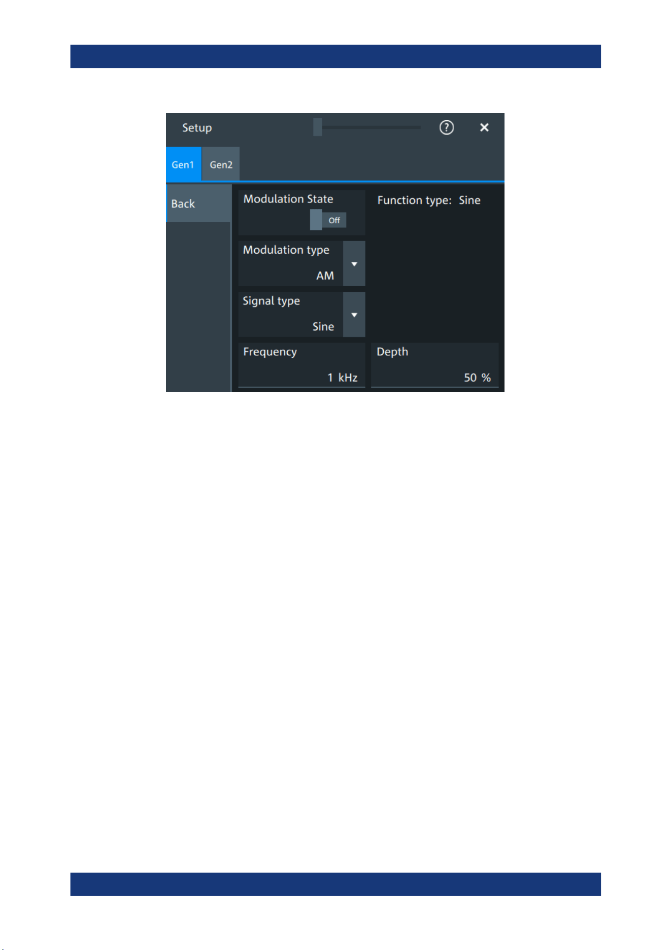
Waveform generator (option R&S MXO5-B6)
R&S
®
MXO 5 Series
395User Manual 1802.3369.02 ─ 02
Modulation state
Enables or disables modulation.
Modulation is available only for "Function type" = "Sine"/"Square".
Remote command:
WGENerator<wg>:MODulation[:STATe] on page 767
Modulation type
Selects the modulation type, which defines how the carrier signal is modified.
"AM"
Amplitude modulation. The amplitude of the carrier signal is varied
according to the modulation signal.
"FM"
Frequency modulation. The frequency of the carrier signal is varied
according to the modulation signal.
"PWM"
Pulse width modulation. The time for which the signal is in a high
state is varied according to the modulation signal.
"FSK"
Frequency shift keying (FSK) modulation. The signal frequency
switches between "Frequency 1" and "Frequency 2" at a "FSK rate".
Remote command:
WGENerator<wg>:MODulation:TYPE on page 775
Signal type
Selects the type of the modulating signal for AM, FM or PWM modulation.
Remote command:
WGENerator<wg>:MODulation:AM[:FUNCtion] on page 769
WGENerator<wg>:MODulation:FM[:FUNCtion] on page 771
WGENerator<wg>:MODulation:PWM[:FUNCtion] on page 774
Setup of the waveform generator

Waveform generator (option R&S MXO5-B6)
R&S
®
MXO 5 Series
396User Manual 1802.3369.02 ─ 02
Frequency
Sets the frequency of the modulating waveform for AM/FM/PWM modulation.
Remote command:
WGENerator<wg>:MODulation:AM:FREQuency on page 768
WGENerator<wg>:MODulation:FM:FREQuency on page 770
WGENerator<wg>:MODulation:PWM:FREQuency on page 774
Depth
Sets the modulation depth, the percentage of the amplitude range that is used for AM
modulation.
Remote command:
WGENerator<wg>:MODulation:AM:DEPTh on page 768
Duty cycle
Sets the duty cycle for a square waveform. The duty cycle expresses for what percent-
age fraction of the period, the waveform is active, i.e. the signal state is high.
Remote command:
WGENerator<wg>:MODulation:AM:DCYCle on page 767
WGENerator<wg>:MODulation:FM:DCYCle on page 770
WGENerator<wg>:MODulation:PWM:DCYCle on page 773
Symmetry
Sets the symmetry for the ramp modulation waveform, the percentage of time that the
waveform is rising.
Remote command:
WGENerator<wg>:MODulation:AM:SYMMetry on page 768
WGENerator<wg>:MODulation:FM:SYMMetry on page 771
WGENerator<wg>:MODulation:PWM:SYMMetry on page 774
Deviation
Sets the frequency deviation, the maximum difference between the FM modulated sig-
nal and the carrier signal.
Remote command:
WGENerator<wg>:MODulation:FM:DEViation on page 770
Modulation depth
Sets the modulation depth, the percentage of the amplitude range that is used for
PWM modulation.
Remote command:
WGENerator<wg>:MODulation:PWM:DEPTh on page 773
Frequency 1/Frequency 2
Sets the frequency of the first /second signal in FSK modulated signal.
Remote command:
WGENerator<wg>:MODulation:FSK:FONE on page 771
WGENerator<wg>:MODulation:FSK:FTWO on page 771
Setup of the waveform generator
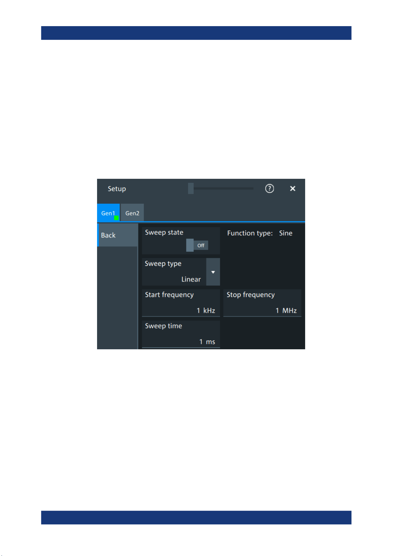
Waveform generator (option R&S MXO5-B6)
R&S
®
MXO 5 Series
397User Manual 1802.3369.02 ─ 02
FSK rate
Sets the frequency at which signal switches between "Frequency 1" and "Frequency
2".
Remote command:
WGENerator<wg>:MODulation:FSK[:RATE] on page 772
15.1.3 Sweep settings
Sweep is available only for sine waveforms.
Access: "Gen" signal activator > "Gen1" or "Gen2" > "Setup" tab > "Function type" =
"Sine" > "Sweep".
In the sweep mode, the R&S MXO 5 generates a signal whose frequency gradually
changes from the "Start frequency" to the "Stop frequency" for a certain "Sweep time".
For a step-by-step description of the sweep setup, see Chapter 15.3.3, "Configuring a
sine sweep waveform", on page 405.
Sweep state
Enables or disables the sweeping.
Remote command:
WGENerator<wg>:SWEep[:STATe] on page 777
Sweep type
Sets the type of the sweep, a linear or logarithmic change of the frequency.
Remote command:
WGENerator<wg>:SWEep:TYPE on page 778
Setup of the waveform generator

Waveform generator (option R&S MXO5-B6)
R&S
®
MXO 5 Series
398User Manual 1802.3369.02 ─ 02
Start frequency
Sets the start frequency of the sweep signal.
Remote command:
WGENerator<wg>:SWEep:FSTart on page 778
Stop frequency
Sets the stop frequency of the sweep signal.
Remote command:
WGENerator<wg>:SWEep:FEND on page 778
Sweep time
Sets the duration of the sweep.
Remote command:
WGENerator<wg>:SWEep:TIME on page 778
15.1.4 Arbitrary waveforms
The arbitrary waveform generator allows you to output a user-defined waveform for
testing your devices. An arbitrary waveform is copied from an existing waveform on the
instrument, or loaded from file. You can load CSV files that follow a defined structure,
or saved reference waveforms.
See also: Chapter 15.3.4, "Configuring an arbitrary waveform", on page 405.
15.1.4.1 Arbitrary waveform files
You can load CSV files that have a Rohde & Schwarz WaveGen format.
Content and format of the Rohde & Schwarz arbitrary waveform CSV files
The waveform generator format can contain the following values:
●
Rate
●
Time value
●
Voltage value
If all the values are defined, the file format is as follows:
Rate = 5000000 //Sample rate of the arbitrary waveform.
0.000000E+000,-5.995 //Time value 1, Voltage value 1
1.237011E-005,-6.0 //Time value 2, Voltage value 2
.......
In this case, the rate is reflected in the "Sample Rate" field of the user interface. The
total number of Time/Voltage values is reflected in the "Samples" of the user interface.
Anything written after // is ignored as a comment.
You can define only some of the values. According to what you define, the file format
looks different and is handled differently:
●
With specified Rate:
Setup of the waveform generator

Waveform generator (option R&S MXO5-B6)
R&S
®
MXO 5 Series
399User Manual 1802.3369.02 ─ 02
Time values are ignored. You can specify just rate and voltage values as below:
Rate = 5000000 //Sample rate of the arbitrary waveform
-5.995 //Voltage value 1
-6.0 //Voltage value 2
.......
●
Without specified Rate and without specified Time values:
The last user-defined sample rate is used to calculate the waveform. You can
change the "Sample rate" in the user interface. The voltage values are then played
with this sample rate.
-5.995 //Voltage value 1
-6.0 //Voltage value 2
.......
●
Without specified Rate and with specified Time:
The timing information of the first 2 time values is used to calculate the sample
rate.
Example:
Consider the following file:
0.000000E+000,-5.995 //Time value 1, Voltage value 1
1.237011E-005,-6.0 //Time value 2, Voltage value 2
The sample rate is:
Sample rate = 1/ Time between first two samples =1 / 1.237011E-005 =
80.840KSampe/sec
15.1.4.2 Arbitrary settings
Access: "Gen" signal activator> "Gen1" or "Gen2" > "Setup" tab > "Function type" =
"Arbitrary"
The following settings in the "Setup" tab and the "Arbitrary Setup" dialog are specific
for generated arbitrary waveforms.
Setup of the waveform generator
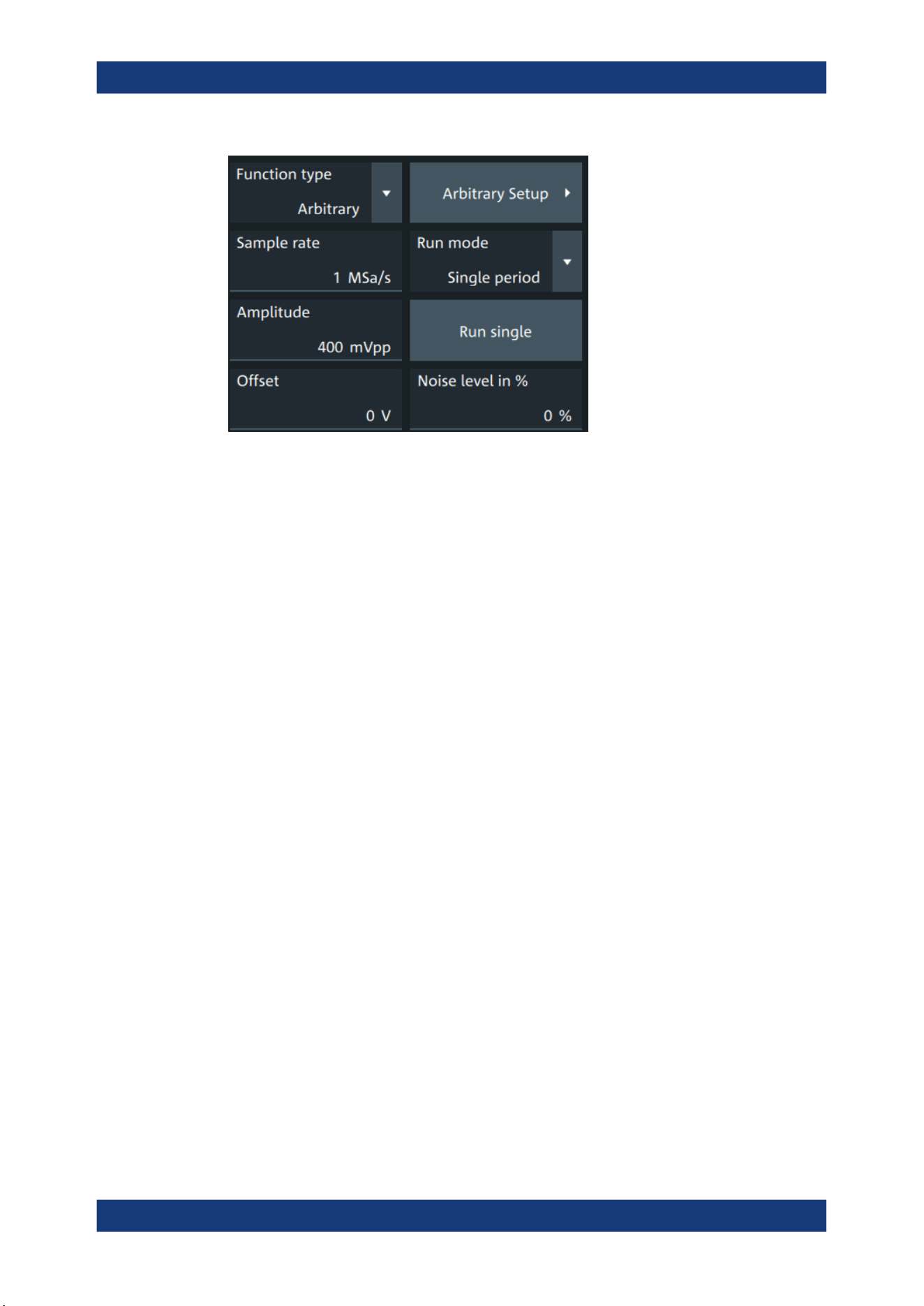
Waveform generator (option R&S MXO5-B6)
R&S
®
MXO 5 Series
400User Manual 1802.3369.02 ─ 02
Run mode....................................................................................................................400
Run single................................................................................................................... 400
Arbitrary Setup............................................................................................................ 400
Arb wfm source........................................................................................................... 401
Sample rate.................................................................................................................401
Number of samples..................................................................................................... 401
Open........................................................................................................................... 401
Run mode
Selects the duration for which the signal of the arbitrary generator is output after the
trigger event. You can choose between a "Continuous" and "Single period" duration.
Remote command:
WGENerator<wg>:ARBGen:RUNMode on page 776
Run single
Generates a single period of the arbitrary waveform if "Run mode" is set to "Single
period".
If you load the arbitrary waveform from file, first load the file, and then connect the
DUT. See also: "Open" on page 401.
Remote command:
WGENerator<wg>:ARBGen:RUNSingle on page 776
Arbitrary Setup
Opens a dialog to define the arbitrary waveform.
Setup of the waveform generator
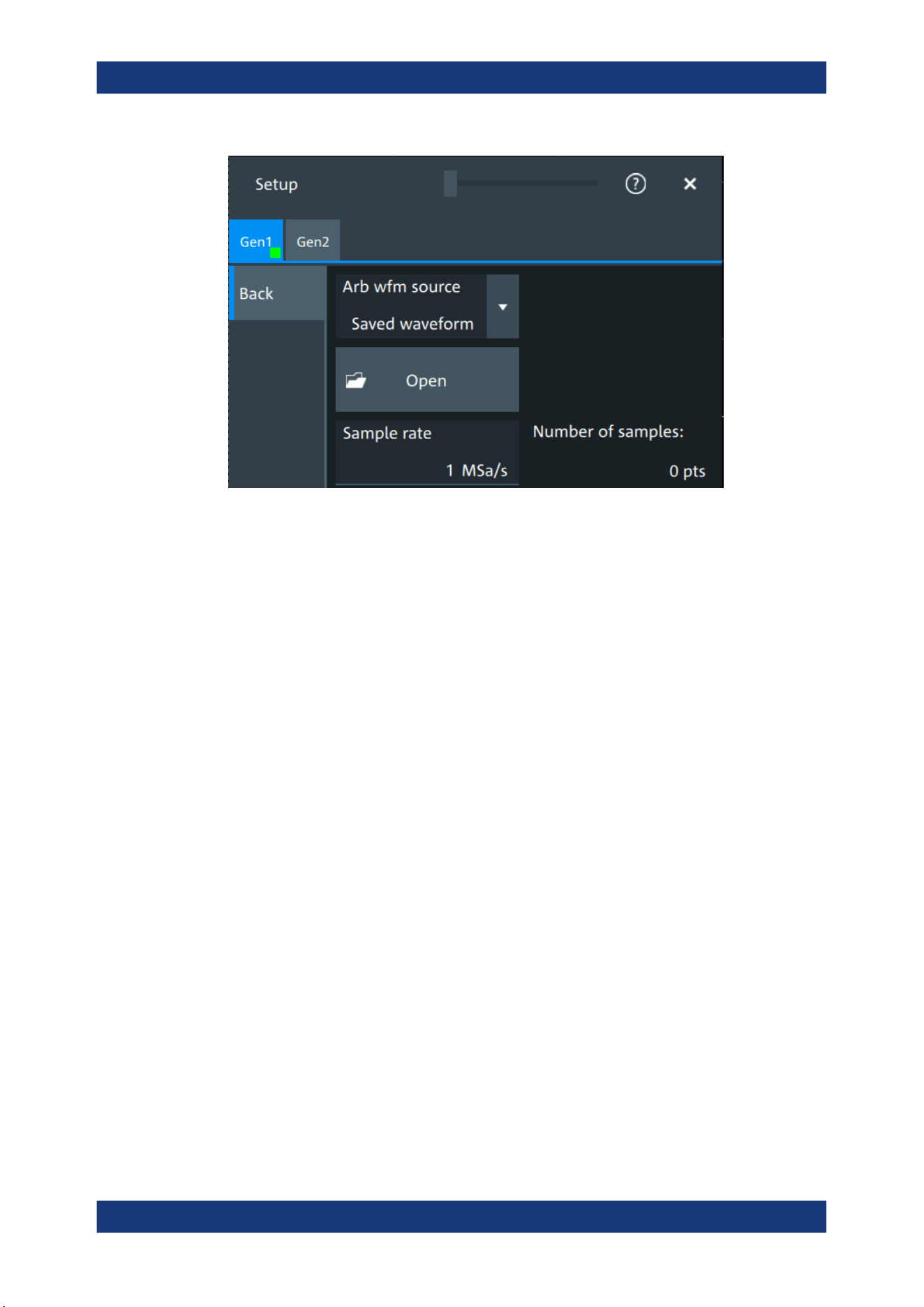
Waveform generator (option R&S MXO5-B6)
R&S
®
MXO 5 Series
401User Manual 1802.3369.02 ─ 02
Arb wfm source
Selects the source of the arbitrary waveform.
You can load CSV files that follow a defined structure, or saved reference waveforms.
See also: "Open" on page 401.
Remote command:
WGENerator<wg>:ARBGen[:SOURce] on page 777
Sample rate
Sets the sample rate for the arbitrary waveform.
If the sample rate is given in the arbitrary waveform file (CSV or REF file), the instru-
ment displays the value here, and you can change it. If no sample rate is available in
the data, you can set the required sample rate.
Remote command:
WGENerator<wg>:ARBGen:SRATe on page 777
Number of samples
Displays the number of samples in the loaded waveform.
Remote command:
WGENerator<wg>:ARBGen:SAMPles? on page 776
Open
Opens a dialog to select the saved waveform, and loads the file. The setting is availa-
ble if "Arb wfm source" is set to "Saved waveform".
You can load CSV files, or REF waveforms (saved reference waveforms). See also:
Chapter 15.1.4.1, "Arbitrary waveform files", on page 398.
When the file is loaded, the output voltage is set to the value of the first sample in the
file. Therefore, if you want to output single periods of the arbitrary waveform, first load
the waveform file, and then connect the DUT.
Setup of the waveform generator
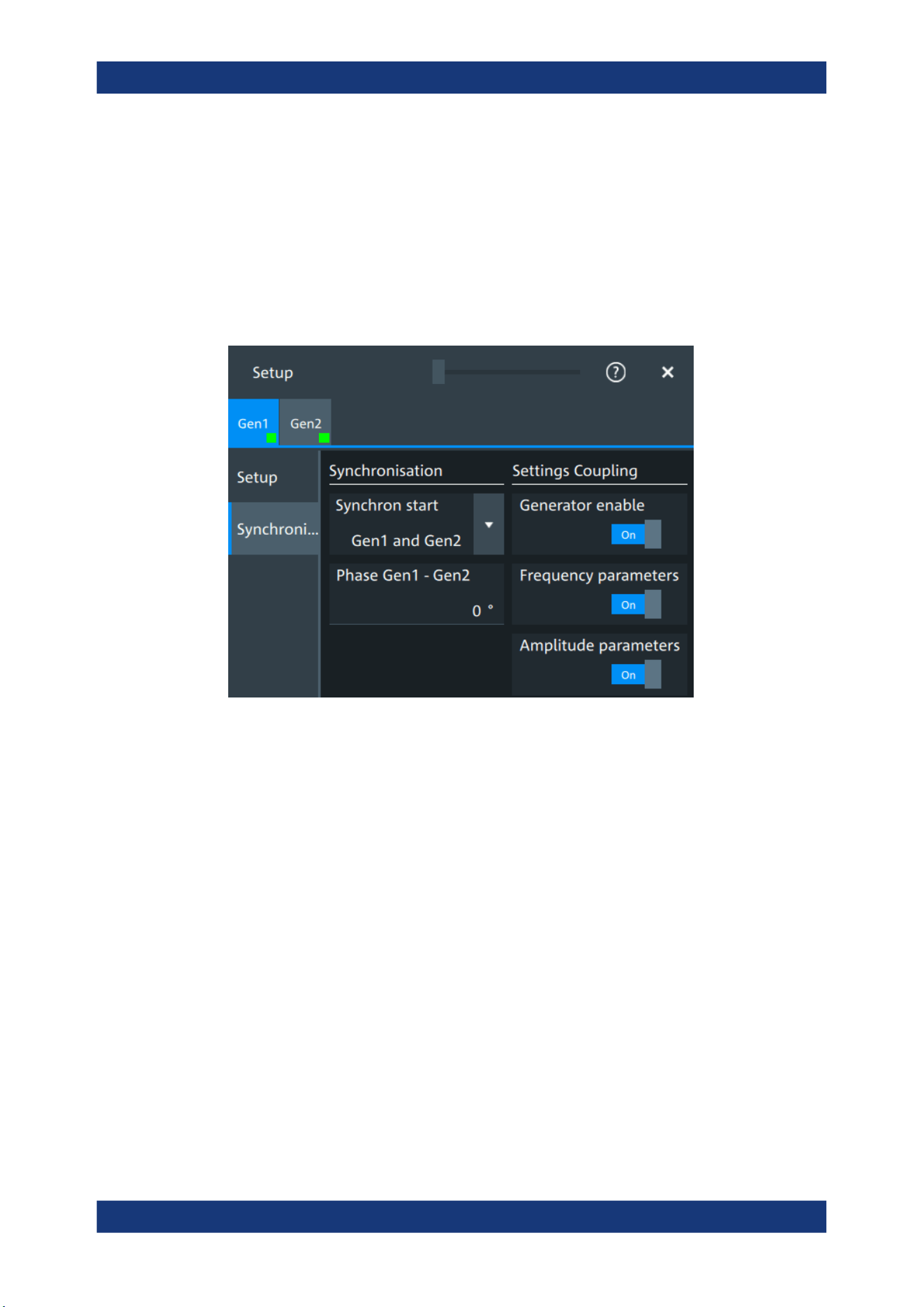
Waveform generator (option R&S MXO5-B6)
R&S
®
MXO 5 Series
402User Manual 1802.3369.02 ─ 02
Remote command:
WGENerator<wg>:ARBGen:NAME on page 775
WGENerator<wg>:ARBGen:OPEN on page 775
15.2 Synchronize settings
Access: "Menu" > "Apps" > "Gen1" > "Synchronisation" tab.
Synchron start
Selects, which signals generated from the waveform generator are synchronized.
Selecting one of the sync options indicates that the first samples of those signals are
generated at the same time, irrespective of if the generators are on or off. Selecting
one of the coupling options automatically syncs the signals generated by the two wave-
form generators.
Remote command:
GENerator:SYNC[:COMBination] on page 780
Generator enable
Enables the coupling of the generators, with the selected set of parameters: amplitude
and frequency.
Remote command:
WGENerator<wg>:COUPling:STATe on page 779
Frequency parameters
Couples all frequency parameters of "Gen1" and "Gen2". The values are taken from
the currently selected generator.
You can still change the other settings of the generators independently.
Synchronize settings

Waveform generator (option R&S MXO5-B6)
R&S
®
MXO 5 Series
403User Manual 1802.3369.02 ─ 02
Remote command:
WGENerator<wg>:COUPling:AMPLitude on page 779
Amplitude parameters
Couples all amplitude parameters of "Gen1" and "Gen2" including the load. The values
are taken from the currently selected generator.
Remote command:
WGENerator<wg>:COUPling[:FREQuency] on page 780
Phase Gen1 - Gen2
Sets the phase shift between the waveform of Gen1 and Gen2 when the frequency
parameters of the two waveforms are coupled.
Remote command:
WGENerator<wg>:COUPling:PHASeshift on page 780
15.3 Configuring the waveform generator
This chapter explains step by step how to configure the waveform generator.
● Configuring a function waveform...........................................................................403
● Configuring a modulation waveform......................................................................403
● Configuring a sine sweep waveform..................................................................... 405
● Configuring an arbitrary waveform........................................................................405
15.3.1 Configuring a function waveform
1. Tap the "Gen" signal activator.
2. Select the tab of the generator that you want to configure: "Gen"1 or "Gen"2.
3. In the "Setup" tab, select the "Function type" that you want to generate, e.g. "Sine".
4. Depending on the selected "Function type", configure the settings of the waveform
like "Frequency" and "Amplitude".
5. If necessary, change the "User load" settings, or add "Noise level in %" to the
waveform.
6. Set "State" = "On" to output the waveform at the output connector of the waveform
generator.
15.3.2 Configuring a modulation waveform
Generating an AM modulated waveform
1. Tap the "Gen" signal activator.
Configuring the waveform generator

Waveform generator (option R&S MXO5-B6)
R&S
®
MXO 5 Series
404User Manual 1802.3369.02 ─ 02
2. Select the tab of the generator that you want to configure: "Gen"1 or "Gen"2.
3. In the "Setup" tab, set the "Function type" = "Sine".
4. Press "Modulation" to open the modulation dialog.
5. Set "Modulation type" = "AM".
6. Set the "Carrier frequency" and the "Carrier period".
7. Tap "Modulation signal", and select the required waveform.
8. Depending on the selected "Modulation signal", configure the settings of the wave-
form like "Modulation freq" and "Modulation depth".
9. Set "Modulation state" = "On" to enable the modulation.
10. Press "Back" to return to the "Setup" tab.
11. Set "State" = "On" to output the waveform at the output connector of the waveform
generator.
Generating an FM modulated waveform
1. Tap the "Gen" signal activator.
2. Select the tab of the generator that you want to configure: "Gen"1 or "Gen"2.
3. In the "Setup" tab, set the "Function type" = "Sine".
4. Press "Modulation" to open the modulation dialog.
5. Set "Modulation type" = "FM".
6. Select the "Signal type".
7. Set the "Frequency" and the "Deviation".
8. Set "Modulation state" = "On" to enable the modulation.
9. Press "Back" to return to the "Setup" tab.
10. Set "State" = "On" to output the waveform at the output connector of the waveform
generator.
Generating an FSK modulated waveform
1. Tap the "Gen" signal activator.
2. Select the tab of the generator that you want to configure: "Gen"1 or "Gen"2.
3. In the "Setup" tab, set the "Function type" = "Sine".
4. Press "Modulation" to open the modulation dialog.
5. Set "Modulation type" = "FSK".
6. Set the "Frequency 1", "Frequency 2" and the "FSK rate".
7. Set "Modulation state" = "On" to enable the modulation.
Configuring the waveform generator

Waveform generator (option R&S MXO5-B6)
R&S
®
MXO 5 Series
405User Manual 1802.3369.02 ─ 02
8. Press "Back" to return to the "Setup" tab.
9. Set "State" = "On" to output the waveform at the output connector of the waveform
generator.
Generating a PWM modulated waveform
1. Tap the "Gen" signal activator.
2. Select the tab of the generator that you want to configure: "Gen"1 or "Gen"2.
3. In the "Setup" tab, set the "Function type" = "Square".
4. Press "Modulation" to open the modulation dialog.
5. Set "Modulation type" = "PWM".
6. Tap "Signal type", and select the required waveform.
7. Configure the settings of the waveform like "Frequency" and "Modulation depth".
8. Set "Modulation state" = "On" to enable the modulation.
9. Press "Back" to return to the "Setup" tab.
10. Set "State" = "On" to output the waveform at the output connector of the waveform
generator.
15.3.3 Configuring a sine sweep waveform
1. Tap the "Gen" signal activator.
2. Select the tab of the generator that you want to configure: "Gen"1 or "Gen"2.
3. In the "Setup" tab, set "Function type" = "Sine".
4. Press "Sweep" to open the sweep dialog.
5. Select the "Sweep type".
6. Set the "Start frequency", the "Stop frequency" and the "Sweep time".
7. Set "Sweep state" = "On" to enable the sweep.
8. Press "Back" to return to the "Setup" tab.
9. Set "State" = "On" to output the waveform at the output connector of the waveform
generator.
15.3.4 Configuring an arbitrary waveform
For a description of the settings, see Chapter 15.1.4, "Arbitrary waveforms",
on page 398.
Configuring the waveform generator

Waveform generator (option R&S MXO5-B6)
R&S
®
MXO 5 Series
406User Manual 1802.3369.02 ─ 02
Generating an arbitrary waveform from a saved file
If you want to output single periods of the arbitrary waveform, first set up the generator,
and then connect the DUT.
1. Tap the "Gen" signal activator.
2. Select the tab of the generator that you want to configure: "Gen1" or "Gen2".
3. In the "Setup" tab, set "Function type" = "Arbitrary".
4. Select "Arbitrary Setup" to open the arbitrary dialog.
5. Set the "Arb wfm source" to "Saved waveform".
6. Set the "Sample rate" if it is not defined in the file data.
7. Check "Number of samples".
8. Select "Back" to return to the "Setup" tab.
9. Select the "Run mode".
10. If "Run mode" = "Repetitive", set "State" = "On" to output the waveform at the out-
put connector of the waveform generator.
11. If "Run mode" = "Single period":
a) Connect the DUT.
b) Set "State" = "On" to enable the output of the waveform generator.
c) Tap "Run single" to output one waveform.
Generating an arbitrary waveform from the scope waveform
1. Tap the "Gen" signal activator.
2. Select the tab of the generator that you want to configure: "Gen1" or "Gen2".
3. In the "Setup" tab, set "Function type" = "Arbitrary".
4. Select "Arbitrary Setup" to open the arbitrary dialog.
5. Set the "Arb wfm source" to "Scope waveform".
6. Select the "Signal source", the waveform source for the generated waveform.
7. Tap "Update" to load the selected waveform.
8. Press "Back" to return to the "Setup" tab.
9. Select the "Run mode".
10. Set "State" = "On" to enable the output of the generated waveform.
11. If "Run mode" = "Single period", tap "Run single" to output one waveform.
Configuring the waveform generator

Network operation and remote control
R&S
®
MXO 5 Series
407User Manual 1802.3369.02 ─ 02
16 Network operation and remote control
The operating system is the basis of the instrument's firmware, it provides basic func-
tions such as logon, password protection, virus protection, and connection to a net-
work.
In addition to working with the R&S MXO 5 directly, using the touchscreen and the
keys, you can also operate the instrument from a remote PC. Various methods of
remote operation and control in a LAN network are supported:
●
Using the web interface
●
Using a VNC client
●
Remote control with SCPI commands
The following descriptions provide information required for operating the R&S MXO 5
remotely. Definitions specified in the SCPI standard are not provided.
For basic knowledge on remote control operation and additional information, see the
following documents, available on the Rohde & Schwarz website:
●
Remote control via SCPI
● Connecting the instrument to the network (LAN).................................................. 407
● Web interface........................................................................................................410
● Remote operation with VNC client........................................................................ 415
● Remote control......................................................................................................415
● Remote control - status reporting system............................................................. 418
16.1 Connecting the instrument to the network (LAN)
Network environment
Before connecting the product to a LAN, consider the following:
●
Install the latest firmware to reduce security risks.
●
For internet or remote access, use secured connections if applicable.
●
Ensure that the network settings comply with the security policies of your company.
Contact your local system administrator or IT department before connecting your
product to your company LAN.
●
When connected to the LAN, the product may potentially be accessed from the
internet, which may be a security risk. For example, attackers might misuse or
damage the product.
Connecting the instrument to the network (LAN)
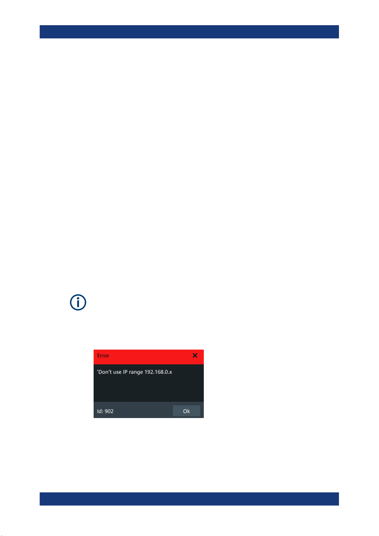
Network operation and remote control
R&S
®
MXO 5 Series
408User Manual 1802.3369.02 ─ 02
16.1.1 Connecting the instrument to the network
There are two methods to establish a LAN connection to the instrument:
●
A non-dedicated network (Ethernet) connection from the instrument to an existing
network.
●
A dedicated network connection (Point-to-point connection) between the instru-
ment and a single computer.
To connect a LAN cable
► Connect an RJ-45 cable to the LAN connector on the rear panel, and to the LAN.
For supported LAN interfaces, refer to the data sheet.
16.1.2 Assigning the IP address
Depending on the network capacities, the TCP/IP address information for the instru-
ment can be obtained in different ways.
●
If the network supports the Dynamic Host Configuration Protocol (DHCP), the
address is assigned automatically.
●
If the network does not support DHCP, or if the instrument is set to use manual
configuration, the addresses must be set manually.
By default, the instrument is configured to use DHCP and obtains all address informa-
tion automatically. Thus it is safe to establish a physical connection to the LAN without
any previous instrument configuration.
Ensure that you do not use the IP address range 192.168.0.x to avoid internal address
conflict.
Setting up a manual IP address within this range is rejected by the firmware. If the
automatic DHCP server assigns an IP address within this range, the instrument is not
reachable from this network.
An error message is displayed, if the firmware detects an IP address error:
To assign the IP address manually on the instrument
1.
NOTICE! Connection errors can affect the entire network. If your network does not
support DHCP, or if you choose to disable dynamic TCP/IP configuration, you must
assign valid address information before connecting the instrument to the LAN.
Connecting the instrument to the network (LAN)

Network operation and remote control
R&S
®
MXO 5 Series
409User Manual 1802.3369.02 ─ 02
Contact your network administrator to obtain a valid IP address.
2. Open "Menu" > "Settings".
3. Select "System" > "Network" > "Advanced".
4. Disable "Automatic IP (DHCP)".
5. Enter the address information as obtained from the network administrator.
16.1.3 Using host names
In a LAN that uses a DNS server (Domain Name System server), each computer and
instrument in the LAN can be accessed via an unambiguous host name (or computer
name) instead of the IP address. The DNS server translates the host name to the IP
address. Host names are useful when a DHCP server is used, as a new IP address
can be assigned each time the instrument is restarted.
Each instrument is delivered with an assigned host name, but you can change this
name.
The default host name is the device name, a non-case-sensitive string with the follow-
ing syntax: <instrument_model>-<serial_number>.
For example, the default host name of an MXO58 with serial number 123456 is
MXO58-123456.
You can find the current host name, the model and the serial number in the "Device
summary", when you tap the Rohde & Schwarz logo in the upper right corner of the
screen. See also: Chapter 4.11, "Information and notifications", on page 65.
The serial number can also be found on the rear panel of the instrument. It is the third
part of the device ID printed on the barcode sticker:
To change the host name
1. Open the "Menu".
2. Select "Settings" > "System" > "Network".
3. In "Device name", enter the new host name.
4. Confirm the entry.
Connecting the instrument to the network (LAN)

Network operation and remote control
R&S
®
MXO 5 Series
410User Manual 1802.3369.02 ─ 02
16.2 Web interface
If the R&S MXO 5 is connected to a computer via LAN, you can operate the instrument
from the computer. No additional tools are required, you need only a web browser.
16.2.1 Settings on the R&S MXO 5
The connection status icon in the upper right corner indicates the status of the LAN
connection. A green icon indicates that the instrument is connected to the LAN; a red
symbol indicates a connection error - mostly the LAN cable is not connected.
The "Network" tab of the "System" dialog box provides network information and set-
tings. See Chapter 5.1.2, "Network settings", on page 70.
16.2.2 Web browser
The instrument's web interface works with all W3C compliant browsers.
1. Open a browser on a computer connected to the instrument via LAN.
2. Type the instrument's host name or IP address in the address field of the browser
on your PC, e.g. "http://11.111.11.222".
The instrument homepage opens.
The instrument homepage displays the device information in read-only format, includ-
ing DNS host names and the VISA resource string.
The navigation menu if the browser interface has the following items:
●
"LAN configuration" opens the menu with configuration pages.
●
"Web control" emulates the front panel and shows the instrument display. You see
a live image of the instrument, and you can operate the instrument remotely. You
can use the keys, the knobs and the menus in the same way as directly on the
instrument.
●
"File manager" provides access to the user data that is saved on the instrument,
upload and download.
16.2.2.1 LAN configuration
The LAN configuration consists of several parts:
●
"General"
●
"IP configuration" provides all mandatory LAN parameters.
●
"Advanced configuration" provides LAN settings that are not declared mandatory
by the standard.
●
"Ping client" provides the ping utility to verify the connection between the instru-
ment and other devices.
Web interface
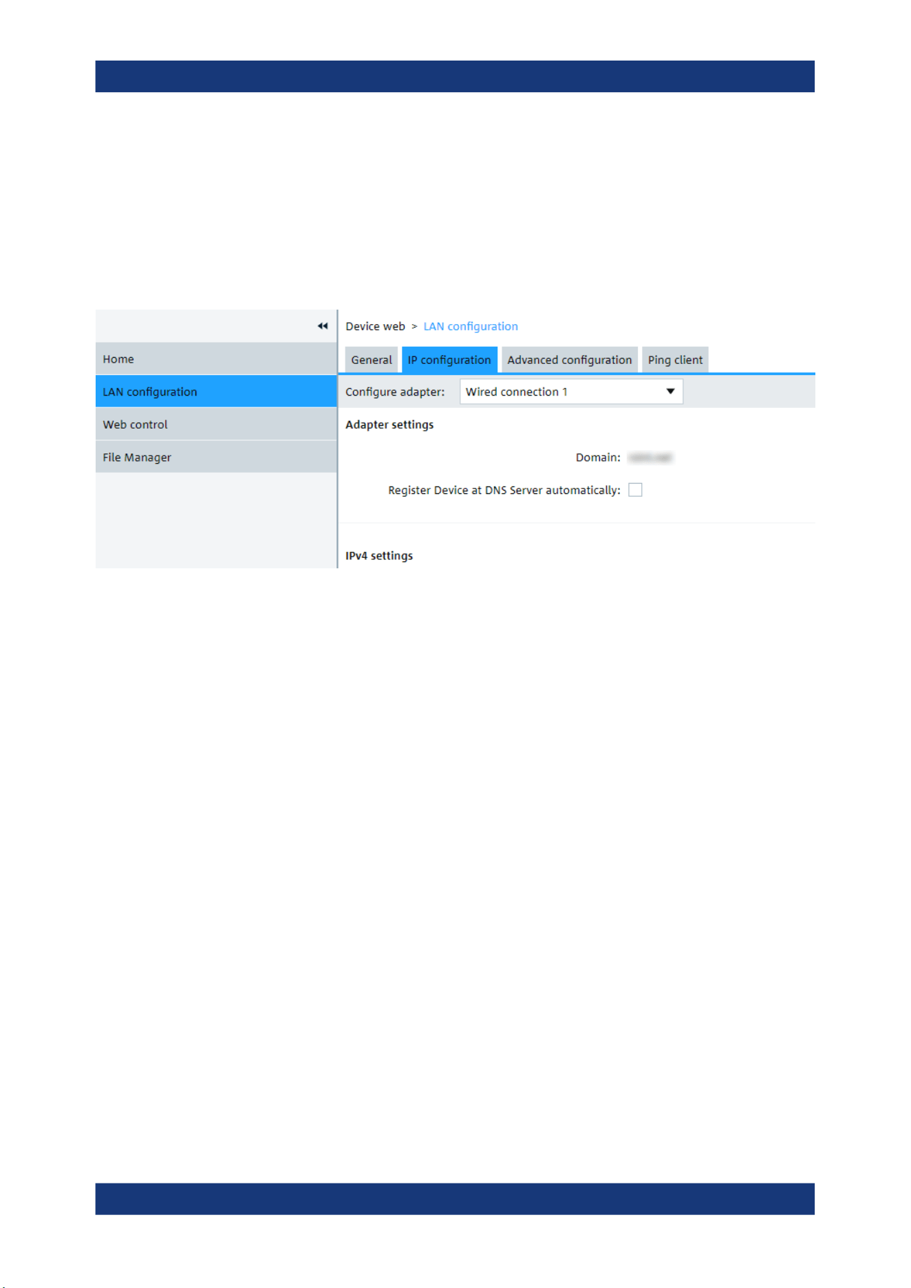
Network operation and remote control
R&S
®
MXO 5 Series
411User Manual 1802.3369.02 ─ 02
Changing the LAN parameters requires the "Web Ifc Password" password, which is set
on the instrument.
IP configuration
The "LAN Configuration > IP configuration" webpage displays all mandatory LAN
parameters and allows their modification. Changing the LAN parameters requires the
"Web Ifc Password" password, which is set on the instrument.
The "IP address mode" controls how the IP address for the instrument gets assigned.
For the manual configuration mode, at least the static IP address, subnet mask, and
default gateway are used to configure the LAN. The automatic configuration mode
uses DHCP server or Dynamic Link Local Addressing to obtain the instrument IP
address.
The same settings are available on the instrument under "Menu" > "Settings" > "Sys-
tem" > "Network" > "Advanced".
Advanced configuration
The "LAN Configuration > Advanced configuration" parameters are used as follows:
●
mDNS and DNS-SD are two additional protocols: Multicast DNS and DNS Service
Discovery. They are used for device communication in zero configuration networks
working without DNS and DHCP.
●
"ICMP ping" must be enabled to use the ping utility.
●
"VXI-11" is the protocol that is used to detect the instrument in the LAN.
Web interface
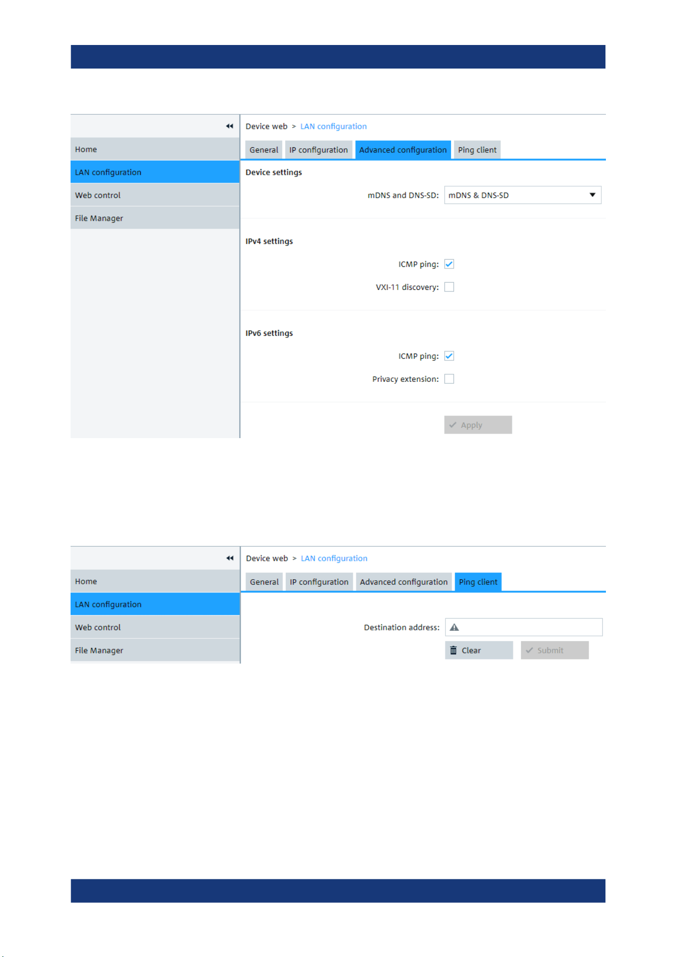
Network operation and remote control
R&S
®
MXO 5 Series
412User Manual 1802.3369.02 ─ 02
Ping client
Ping is a utility that verifies the connection between the instrument and another device.
The ping command uses the ICMP echo request and echo reply packets to determine
whether the LAN connection is functional. Ping is useful for diagnosing IP network or
router failures. The ping utility is not password-protected.
To initiate a ping between the compliant instrument and a second connected device:
1. Enable "ICMP ping" on the "Advanced configuration" page (enabled by default).
2. On the "Ping client" page, enter the IP address of the second device without the
ping command and without any further parameters into the "Destination
address" field (e.g. 11.113.11.203).
3. Click "Submit".
Web interface
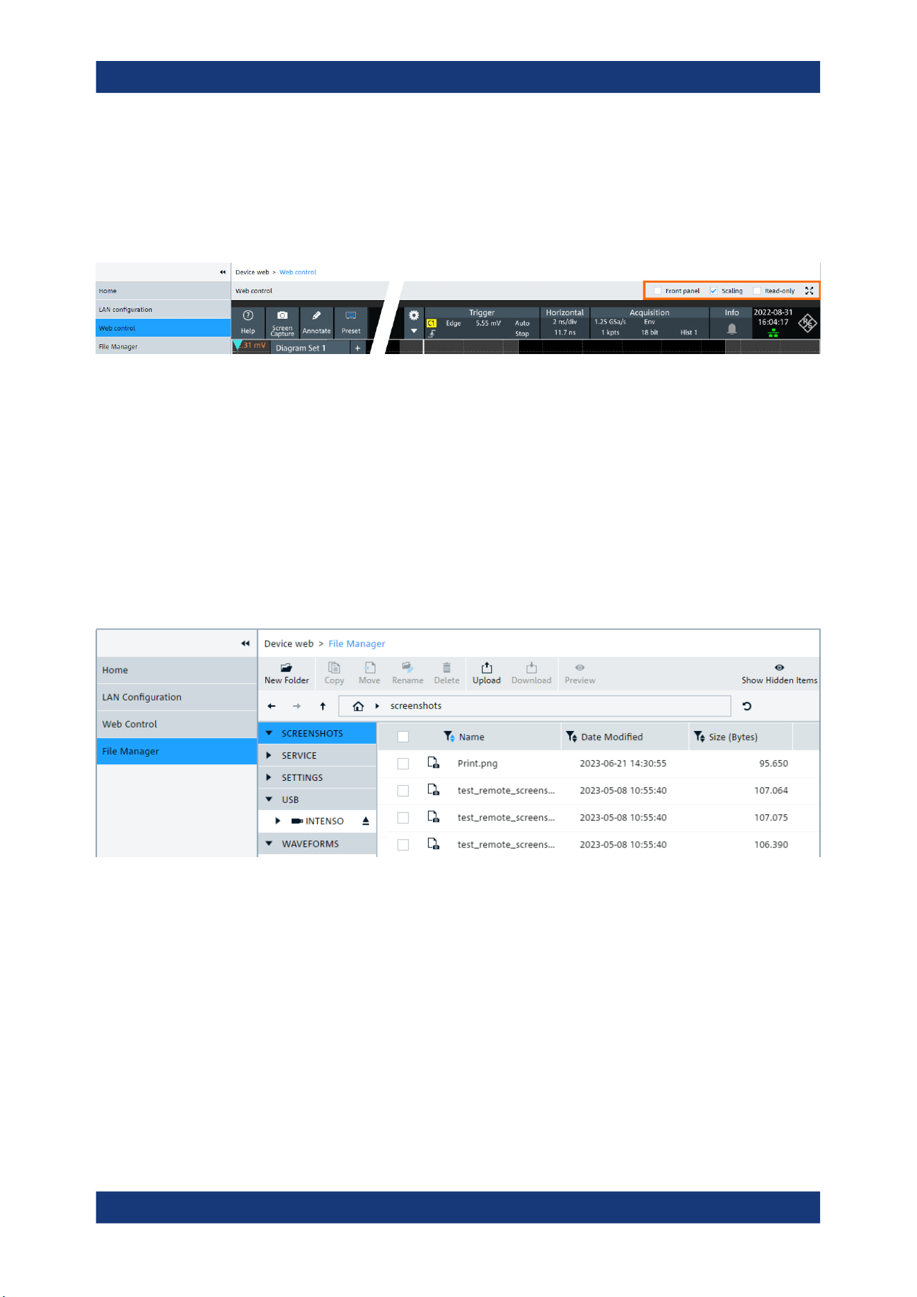
Network operation and remote control
R&S
®
MXO 5 Series
413User Manual 1802.3369.02 ─ 02
16.2.2.2 Web control
"Web Control" emulates the front panel and shows the instrument display. You see a
live image of the instrument, and you can operate the instrument remotely. You can
use the keys, the knobs and the menus in the same way as directly on the instrument.
In the upper right corner above the emulated display, you see some options:
●
"Front panel" hides or shows the front panel.
●
"Scaling" scales the diagram to show it completely. If disabled, the diagram is
shown in its original size.
●
"Read-only" disables operating, only viewing is possible
●
The arrows icon hides or shows the menu.
16.2.2.3 File manager
The file manager on the instrument's webpage provides access to the user data that is
stored on the instrument, or on a USB flash device connected to the instrument.
In the web file manager, you can organize the data:
●
Create folders
●
Copy files within the instrument's file system, or from and to USB flash device. Mul-
tiple files selection is possible.
●
Move files within the instrument's file system, or from and to USB flash device. Mul-
tiple files selection is possible.
●
Rename files
●
Delete files
●
Upload files from the operating computer to the instrument. Multiple files can be
uploaded at once.
Web interface

Network operation and remote control
R&S
®
MXO 5 Series
414User Manual 1802.3369.02 ─ 02
●
Download files from the instrument to the operating computer. Multiple files selec-
tion is possible.
●
Preview file content of text files with maximum size of 500 kbyte.
After attaching a USB flash device, creating a screenshot or other actions, the file man-
ager might not display the last change:
► Click the "Refresh" icon on the right of the address field to update the display.
Note that the "Eject" button for USB flash devices has no function when operating the
instrument remotely.
16.2.2.4 Mapping the instrument's file system as network drive
Using web-based distributed authoring and versioning (WebDAV), you can access and
exchange files over the internet: move, cut, copy and paste files from the instrument to
the computer and vice versa. Therefore, map the instrument's file system as network
drive in the file explorer of the operating computer:
The instrument is connected to LAN, and the connection status icon in the upper right
corner of the instrument's display is green.
1. Open the file explorer on the operating computer.
2. In the left list, right-click "Network" or the entry of the operating computer, and
select "Map network drive".
3. Enter the path to the instrument's file system:
http://<hostname>/webdavData.
Example: http://MXO58-123456/webdavData
You can find the hostname in the "Device summary", which is shown when you tap
the Rohde & Schwarz logo in the upper right corner of the instrument's screen. The
default host name is <instrument_model>-<serial_number>.
4. Activate "Connect using different credentials".
5. Click "Finish".
Web interface

Network operation and remote control
R&S
®
MXO 5 Series
415User Manual 1802.3369.02 ─ 02
6. Leave the "User name" and "Password" empty. Click "OK".
If there are problems with the connection, check if the "WebClient" service is running:
"Task Manager" > "Services" tab. If the "WebClient" service is not running, start it.
16.3 Remote operation with VNC client
If the R&S MXO 5 is connected to a computer via LAN, you can operate the instrument
from the computer using a VNC client. Therefore, install a VNC client on the computer.
To operate the instrument via VNC client:
1. Start the VNC client.
2. Enter the hostname (device name) of the instrument. You find the name in the
instrument information on the oscilloscope. Tap the Rohde & Schwarz logo to show
the information.
3. Connect to the instrument.
You see the display of the oscilloscope and can use the menus, dialogs, SmartGrid
and all operating means of the display.
16.4 Remote control
Remote control automates the operation of the instrument using SCPI commands,
scripts and programs.
For general information on remote control of Rohde & Schwarz products via SCPI,
refer to www.rohde-schwarz.com/rc-via-scpi.
The following sections describe the instrument-specific basics of remote control. SCPI
commands are listed and described in chapter Chapter 17, "Remote control com-
mands", on page 428.
● Remote control interfaces and protocols...............................................................415
● Starting and stopping remote control.................................................................... 417
16.4.1 Remote control interfaces and protocols
The instrument supports different interfaces for remote control. The following table
gives an overview.
Remote control

Network operation and remote control
R&S
®
MXO 5 Series
416User Manual 1802.3369.02 ─ 02
Table 16-1: Remote control interfaces and protocols
Interface Protocols, VISA address string Remarks
Local Area
Network
(LAN)
Protocol HiSLIP
VISA address string:
TCPIP::<host address>::
hislip0[,<port>][::INSTR]
Protocol VXI-11
VISA address string:
TCPIP::<host address>[::
inst0]::[INSTR]
The LAN connector is located on rear panel of the
instrument.
The interface is based on TCP/IP and supports vari-
ous protocols.
16.4.1.1 LAN interface
To be integrated in a LAN, the instrument is equipped with a LAN interface, consisting
of a connector, a network interface card and protocols. The interface details are given
in the specifications.
For remote control via a network, the PC and the instrument must be connected via the
LAN interface to a common network with TCP/IP network protocol. They are connected
using a commercial RJ-45 cable (shielded or unshielded twisted-pair category 5 or bet-
ter). The TCP/IP network protocol and the associated network services are preconfig-
ured on the instrument. Software for instrument control and the VISA program library
must be installed on the controller.
IP address
Only the IP address or a valid DNS host name is required to set up the connection.
The host address is part of the "VISA resource string" used by programs to identify and
control the instrument. The VISA resource string has the form:
TCPIP::<host address>::hislip0[,<port>][::INSTR] for HiSLIP protocol
TCPIP::<host address>[::inst0][::INSTR] for VXI-11 protocol
Where:
●
host address identifies the instrument in the network, usually the IP address. If
the LAN is supported by a DNS server, the host name can be used instead of the
IP address. The DNS server (Domain Name System server) translates the host
name to the IP address.
●
hislip0 indicates the HiSLIP protocol.
●
inst0 is the default LAN device name. VISA supports several devices running on
the instrument. On R&S MXO 5, only one device is configured, so the LAN device
name can be omitted.
●
INSTR specifies a VISA resource of the type INSTR. By default, the VISA resource
name control is set to the INSTR class.
Remote control

Network operation and remote control
R&S
®
MXO 5 Series
417User Manual 1802.3369.02 ─ 02
Example: HiSLIP
IP address is 192.1.2.3: the valid resource string is: TCPIP::192.1.2.3::hislip0
Instrument name is RSRT1: the valid resource string is: TCPIP::RSRT1::hislip0.
DNS host name is MXO5-123456: the valid resource string is:
TCPIP::MXO5-123456::hislip0.
Example: VXI-11
IP address is 192.1.2.3: the valid resource string is: TCPIP::192.1.2.3
Instrument name is RSRT1: the valid resource string is: TCPIP::RSRT1.
DNS host name is MXO5-123456: the valid resource string is:
TCPIP::MXO5-123456.
16.4.2 Starting and stopping remote control
16.4.2.1 Starting a remote control session
When you switch on the instrument, it is always in manual operation state ("local"
state). It can be operated via the front panel, the touchscreen and external keyboard
and/or mouse.
► To start remote control:
● Send a command from the controller.
● VXI-11 protocol (LAN or USB interface): Use >R interface message.
While remote control is active, the instrument settings are optimized for maximum
measurement speed; the display is switched off. Operation via the front panel is dis-
abled.
On the touchscreen, two buttons appear in the upper left corner: "Local" and "View".
16.4.2.2 Using the display during remote control
You can observe the screen while a remote control script is executed. Displaying the
results of script execution is helpful for program test purposes but tends to slow down
the measurement. Therefore it is recommended that you switch off the display in real
measurement applications where a tested program script is to be executed repeatedly.
► To switch on the display, do one of the following:
● Tap the "View" button in the upper left corner of the touchscreen.
● Use the SYSTem:DISPlay:UPDate ON command.
► To switch off the display, do one of the following:
● Tap the "View" button again.
Remote control

Network operation and remote control
R&S
®
MXO 5 Series
418User Manual 1802.3369.02 ─ 02
● Use the SYSTem:DISPlay:UPDate OFF command.
16.4.2.3 Returning to manual operation
The instrument switches back to manual operation when the remote connection is
closed. Besides, you can return to manual operation manually or via remote control.
► To return to manual operation:
● Tap the "Local" button in the upper left corner of the touchscreen.
● VXI-11 protocol: Use >L interface message.
16.5 Remote control - status reporting system
The status reporting system stores all information on the current operating state of the
instrument, and on errors which have occurred. This information is stored in the status
registers and in the error queue. Both can be queried via STATus... commands.
16.5.1 Hierarchy of status registers
As shown in the following figure, the status information is of hierarchical structure.
Remote control - status reporting system
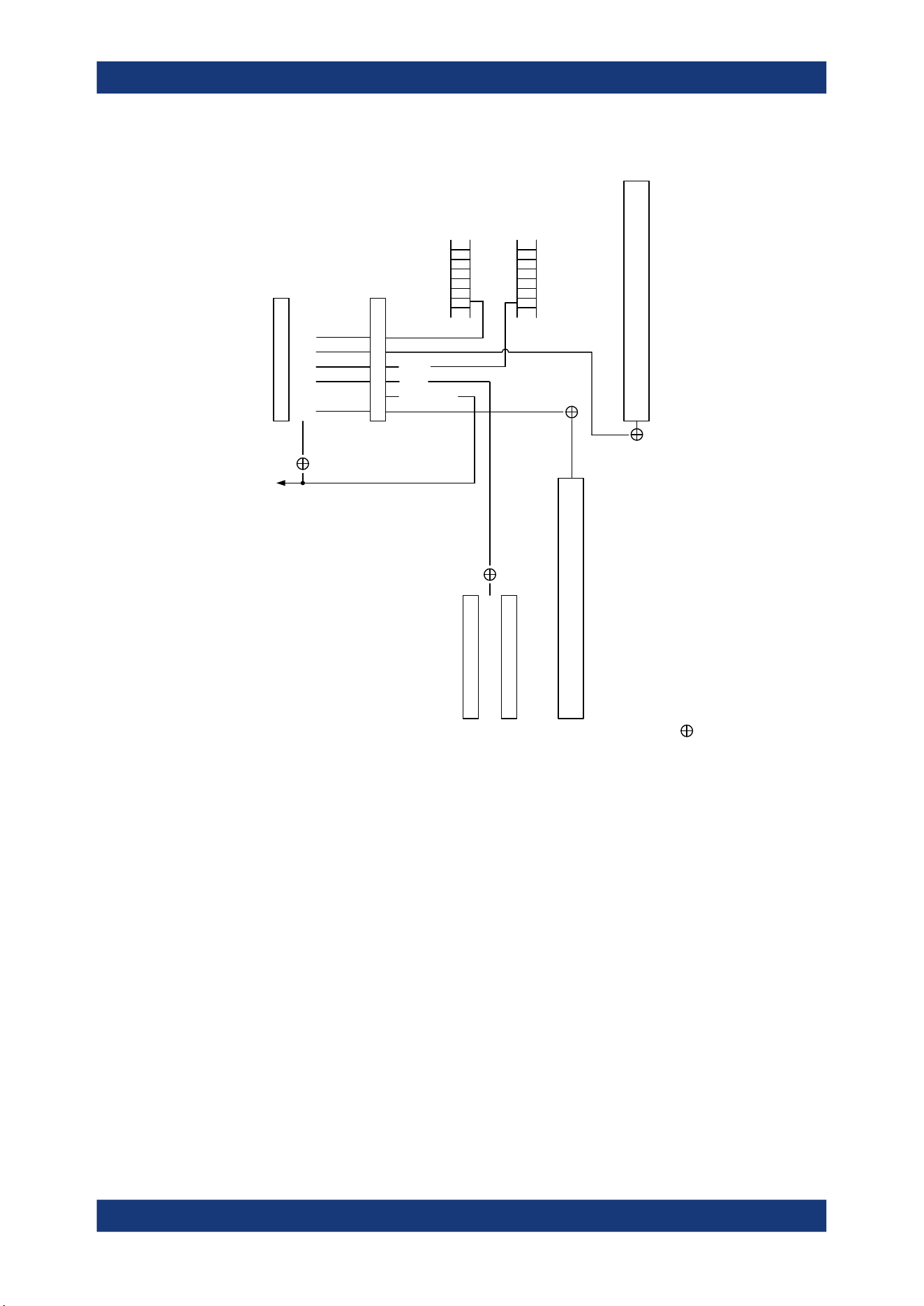
Network operation and remote control
R&S
®
MXO 5 Series
419User Manual 1802.3369.02 ─ 02
0
1
2
3
4
5
6
7
STBSRE
-&-
-&-
-&-
-&-
-&-
ESB
MAV
RQS/MSS
SRQ
Output
buffer
Error/event
queue
-&-
-&-
-&-
-&-
-&-
-&-
-&-
-&-
0
1
2
3
4
5
6
7
ESRESE
0
1
2
3
4
5
6
7
& = logical AND
STATus:OPERation
STATus:QUEStionable
0
1
2
3
4
5
6
7
8
9
10
11
12
13
14
15
0
1
2
3
4
5
6
7
8
9
10
11
12
13
14
15
CALibrating
AUToset
MEASuring
WTRIgger
TRIggered
= logical OR
PPSupply
POVerload
COVerload
TEMPerature
ADCState
GOVerloadN
NOALigndata
LIMit
MARGin
IMPrecise
PLLunlock
Figure 16-1: Overview of the status registers hierarchy
●
STB, SRE
The STatus Byte (STB) register and its associated mask register Service Request
Enable (SRE) form the highest level of the status reporting system. The STB pro-
vides a rough overview of the instrument status, collecting the information of the
lower-level registers.
●
ESR and SCPI registers
The STB receives its information from the following registers:
– The Event Status Register (ESR) with the associated mask register standard
Event Status Enable(ESE).
– The STATus:OPERation and STATus:QUEStionable registers which are
defined by SCPI and contain detailed information on the instrument.
●
Output buffer
Remote control - status reporting system
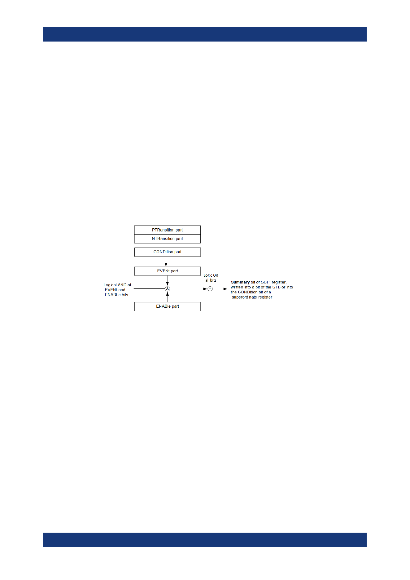
Network operation and remote control
R&S
®
MXO 5 Series
420User Manual 1802.3369.02 ─ 02
The output buffer contains the messages that the instrument returns to the control-
ler. It is not part of the status reporting system but determines the value of the MAV
bit in the STB and thus is represented in the overview.
All status registers have the same internal structure.
16.5.2 Structure of a SCPI status register
The STATus:OPERation and the STATus:QUEStionable SCPI status registers
consists of five parts.
The individual bits are independent of each other, i.e. each hardware status is
assigned a bit number, which is valid for all five parts. Bit 15 (the most significant bit) is
set to zero for all parts. Thus, the contents of the register parts can be processed by
the controller as positive integers.
Description of the five status register parts
The five parts of a SCPI status register have different properties and functions:
●
CONDition
The CONDition part reflects the current instrument status. For summary bits, the
CONDition bit mirrors the sum of the enabled EVENt bits of the next lower regis-
ter.
This register part can only be read, but not written into or cleared. Its contents are
not affected by reading.
●
PTRansition / NTRansition
The two transition register parts define which state transition of the CONDition
part (none, 0 to 1, 1 to 0 or both) is stored in the EVENt part.
The Positive-TRansition part acts as a transition filter. When a bit of the
CONDition part is changed from 0 to 1, the associated PTR bit decides whether
the EVENt bit is set to 1.
– PTR bit =1: the EVENt bit is set.
– PTR bit =0: the EVENt bit is not set.
All positive transitions are enabled by default.
This part can be written into and read as required. Its contents are not affected by
reading.
Remote control - status reporting system

Network operation and remote control
R&S
®
MXO 5 Series
421User Manual 1802.3369.02 ─ 02
The Negative-TRansition part also acts as a transition filter. When a bit of the
CONDition part is changed from 1 to 0, the associated NTR bit decides whether
the EVENt bit is set to 1.
– NTR bit =1: the EVENt bit is set.
– NTR bit =0: the EVENt bit is not set.
All negative transitions are disabled by default.
This part can be written into and read as required. Its contents are not affected by
reading.
●
EVENt
The EVENt part indicates whether an event has occurred since the last reading. It
is the "memory" of the condition part. It allows you to detect the occurrence of
events reliably, even if they have changed the state of the CONDition bit for a
very brief interval. It only indicates events passed on by the transition filters.
This part can only be read by the user. Reading the register clears it.
●
ENABle
The ENABle part determines whether the associated EVENt bit contributes to the
summary bit (see below). Each bit of the EVENt part is "ANDed" with the associ-
ated ENABle bit (symbol '&'). The results of all logical operations of this part are
passed on to the summary bit via an "OR" function (symbol '+').
ENABle bit = 0: the associated EVENt bit does not contribute to the summary bit
ENABle bit = 1: if the associated EVENt bit is "1", the summary bit is set to "1" as
well.
This part can be written into and read by the user as required. Its contents are not
affected by reading.
16.5.3 Contents of the status registers
16.5.3.1 Status byte (STB) and service request enable register (SRE)
The STatus Byte (STB) is already defined in IEEE 488.2. It provides a rough over-
view of the instrument status by collecting the pieces of information of the lower regis-
ters. A special feature is that bit 6 acts as the sum bit of the remaining bits of the status
byte.
The STB can thus be compared with the CONDition part of an SCPI register and
assumes the highest level within the SCPI hierarchy.
The STB is read using the command *STB? or a serial poll.
The STatus Byte (STB) is linked to the Service Request Enable (SRE) register.
Each bit of the STB is assigned a bit in the SRE. Bit 6 of the SRE is ignored. If a bit is
set in the SRE and the associated bit in the STB changes from 0 to 1, a service
request (SRQ) is generated. The SRE can be set using the command *SRE and read
using the command *SRE?.
Remote control - status reporting system

Network operation and remote control
R&S
®
MXO 5 Series
422User Manual 1802.3369.02 ─ 02
Table 16-2: Meaning of the bits used in the status byte
Bit No. Meaning
0...1 Not used
2 Error Queue not empty
The bit is set when an entry is made in the error queue. If this bit is enabled by the SRE, each
entry of the error queue generates a service request. Thus an error can be recognized and
specified in greater detail by polling the error queue. The poll provides an informative error mes-
sage. This procedure is to be recommended since it considerably reduces the problems
involved with remote control.
3 QUEStionable status register summary bit
The bit is set if an EVENt bit is set in the QUEStionable status register and the associated
ENABle bit is set to 1. A set bit indicates a questionable instrument status, which can be speci-
fied in greater detail by querying the STATus:QUEStionable status register.
4 MAV bit (message available)
The bit is set if a message is available in the output queue which can be read. This bit can be
used to enable data to be automatically read from the instrument to the controller.
5 ESB bit
Sum bit of the event status register. It is set if one of the bits in the event status register is set
and enabled in the event status enable register. Setting of this bit indicates a serious error which
can be specified in greater detail by polling the event status register.
6 MSS bit (main status summary bit)
The bit is set if the instrument triggers a service request. This is the case if one of the other bits
of this registers is set together with its mask bit in the service request enable register SRE.
7 STATus:OPERation status register summary bit
The bit is set if an EVENt bit is set in the OPERation status register and the associated
ENABle bit is set to 1. A set bit indicates that the instrument is just performing an action. The
type of action can be determined by querying the STATus:OPERation status register.
16.5.3.2 Event status register (ESR) and event status enable register (ESE)
The ESR is defined in IEEE 488.2. It can be compared with the EVENt part of a SCPI
register. The event status register can be read out using command *ESR?.
The ESE corresponds to the ENABle part of a SCPI register. If a bit is set in the ESE
and the associated bit in the ESR changes from 0 to 1, the ESB bit in the STB is set.
The ESE register can be set using the command *ESE and read using the command
*ESE?.
Table 16-3: Meaning of the bits used in the event status register
Bit No. Meaning
0 Operation complete
This bit is set on receipt of the command *OPC exactly when all previous commands have been
executed.
1 Not used
Remote control - status reporting system

Network operation and remote control
R&S
®
MXO 5 Series
423User Manual 1802.3369.02 ─ 02
Bit No. Meaning
2 Query error
This bit is set if the controller wants to read data from the instrument without having sent a
query. It is also set if the controller does not fetch requested data and sends new instructions to
the instrument instead. The cause is often a query which is faulty and hence cannot be execu-
ted.
3 Device-dependent error
This bit is set if a device-dependent error occurs. An error message with a number between
-300 and -399 or a positive error number, which denotes the error in greater detail, is entered
into the error queue.
4 Execution error
This bit is set if a received command is syntactically correct but cannot be performed for other
reasons. An error message with a number between -200 and -300, which denotes the error in
greater detail, is entered into the error queue.
5 Command error
This bit is set if a command is received, which is undefined or syntactically incorrect. An error
message with a number between -100 and -200, which denotes the error in greater detail, is
entered into the error queue.
6 User request
This bit is set when the instrument is switched over to manual control.
7 Power on (supply voltage on)
This bit is set when you turn on the instrument.
16.5.3.3 STATus:OPERation register
In the CONDition part, this register contains information on which actions the instru-
ment is executing. In the EVENt part, it contains information on which actions the
instrument has executed since the last reading.
It can be read using the commands STATus:OPERation:CONDition? or
STATus:OPERation[:EVENt]?, see also Chapter 17.19.2, "STATus:OPERation reg-
ister", on page 781.
Table 16-4: Bits in the STATus:OPERation register
Bit No. Meaning
0
ALIGnment
This bit is set as long as the instrument is performing a self-alignment.
1 Not used
2
AUToset
This bit is set while the instrument is performing an auto setup.
3 Not used
4
MEASuring
The bit is set as long as an acquisition - sampling and postprocessing - is running. In run contin-
uous mode, the bit is always set.
Remote control - status reporting system

Network operation and remote control
R&S
®
MXO 5 Series
424User Manual 1802.3369.02 ─ 02
Bit No. Meaning
5
WTRIgger
Available only for single acquisitions or the first acquisition of continuous acquisitions.
The wait for trigger status bit indicates that the instrument is ready to trigger, and the pre-trigger
time is expired.
The bit is set for as long as a measurement is running.
6
TRIggered
Available only for single acquisitions or the first acquisition of continuous acquisitions.
The triggered status bit indicates that the instrument has been triggered.
7 - 15 Not used
16.5.3.4 STATus:QUEStionable register
This register contains specific information on instrument operation and signal reliability.
It can be read using the commands STATus:QUEStionable:CONDition? and
STATus:QUEStionable[:EVENt]?.
The remote commands for the STATus:QUEStionable register are described in Chap-
ter 17.19, "Status reporting", on page 780.
Table 16-5: Bits in the STATus:QUEStionable register
Bit
No.
Meaning
0 - For future use.
1
PPSupply
This bit is set if probe power supply overload occurs.
2
POVerload
This bit is set if a probe overload occurs.
3
COVerload
This bit is set if a questionable channel overload occurs.
4
TEMPerature
This bit is set if a questionable temperature occurs.
5
ADCState
The bit is set if the signal is clipped on the upper or lower edge of the screen over-
flow of the ADC occurs.
6
GOVerload
This bit is set if a generator overload occurs.
7 - For future use.
8
NOALigndata
This bit is set if no alignment data is available - the instrument is uncalibrated.
9
LIMit
This bit is set if a limit value is violated.
10
MARGin
This bit is set if a margin value is violated, and the limit value is not violated.
11
IMPRecise
This bit is set if the magnitude of the signal is too low to get reliable measurement
results.
12 - For future use.
Remote control - status reporting system

Network operation and remote control
R&S
®
MXO 5 Series
425User Manual 1802.3369.02 ─ 02
Bit
No.
Meaning
13
PLLunlock
This bit is set if a phase-locked loop process is unlocked. There are two reasons:
●
external reference is missing or defect
●
hardware defect of internal PLL
14 - For future use.
16.5.3.5 Application of the status reporting system
The purpose of the status reporting system is to monitor the status of one or several
instruments in a test system. In particular, it monitors continuous measurements to
detect errors in the signal. The controller must receive and evaluate the information of
all devices.
The following standard methods are used:
●
Service request: An SRQ is initiated by the instrument.
●
Query of a specific register by commands
●
Query of the error queue
These methods are described in the following sections.
Service request
The instrument can send a service request (SRQ) to the controller. Usually, this service
request initiates an interrupt at the controller, to which the control program can react
appropriately.
An SRQ is initiated if one or several of bits 2, 3, 4, 5 or 7 of the STB are set and
enabled in the SRE. Each of these bits combines the information of a lower-level regis-
ter, the error queue or the output buffer.
The ENABle parts of the status registers can be set such that arbitrary bits in an arbi-
trary status register initiate an SRQ. To use service requests effectively, set all bits to
"1" in the mask registers SRE and ESE.
The SRQ is the only possibility for the instrument to become active on its own. Config-
ure the instrument so that it initiates a service request if errors occur. And ensure that
your program reacts appropriately to service requests.
Query of a register
The STB and ESR registers contain 8 bits, the SCPI registers 16 bits. The contents of
a status register are specified and transferred as a single decimal number. Therefore,
each bit is assigned a weighted value. The decimal number is calculated as the sum of
the weighted values of all bits in the register that are set to 1.
Remote control - status reporting system

Network operation and remote control
R&S
®
MXO 5 Series
426User Manual 1802.3369.02 ─ 02
Example:
The decimal value 40 = 32 + 8 indicates that bits no. 3 and 5 in the status register (e.g.
the QUEStionable status summary bit and the ESB bit in the STatus byte) are set.
16.5.4 Error queue
Each error state in the instrument leads to an entry in the error queue.
The error queue should be queried after every SRQ in the controller program as the
entries describe the cause of an error more precisely than the status registers. Espe-
cially in the test phase of a controller program the error queue should be queried regu-
larly since faulty commands from the controller to the instrument are recorded there as
well.
16.5.5 Reset values of the status reporting system
The following table contains the different commands and events causing the status
reporting system to be reset. None of the commands, except *RST and
SYSTem:PRESet, influence the functional instrument settings. In particular, DCL does
not change the instrument settings.
Table 16-6: Resets of the status reporting system
Event
DCL, SDC
(Device
Clear,
Selected
Device
Clear)
*RST or
SYSTem:
PRESet
STATus:
PRESet
*CLS
Clear STB, ESR - - - yes
Clear SRE, ESE - - - -
Clear EVENt parts of the registers - - - yes
Clear ENABle parts of all OPERation and
QUEStionable registers;
Fill ENABle parts of all other registers
with "1".
- - yes -
Fill PTRansition parts with "1";
Clear NTRansition parts
- - yes -
Clear error queue - - - yes
Remote control - status reporting system

Network operation and remote control
R&S
®
MXO 5 Series
427User Manual 1802.3369.02 ─ 02
Event
DCL, SDC
(Device
Clear,
Selected
Device
Clear)
*RST or
SYSTem:
PRESet
STATus:
PRESet
*CLS
Clear output buffer yes 1) 1) 1)
Clear command processing and input
buffer
yes - - -
1) The first command in a command line that immediately follows a <PROGRAM MESSAGE TERMINA-
TOR> clears the output buffer.
Remote control - status reporting system

Remote control commands
R&S
®
MXO 5 Series
428User Manual 1802.3369.02 ─ 02
17 Remote control commands
This chapter describes all remote commands available for R&S MXO 5 and provides
examples and information how to use the commands.
For general information on remote control of Rohde & Schwarz products via SCPI,
refer to www.rohde-schwarz.com/rc-via-scpi.
See also Chapter 16.4, "Remote control", on page 415 and Chapter 16.5, "Remote
control - status reporting system", on page 418 for further information on remote con-
trol.
The description of the remote commands, assume a R&S MXO 5 with the highest
available bandwidth and number of channels. Depending on your model, some of the
available command ranges can differ from the values stated in the following chapters.
17.1 Conventions used in remote command description
The basics of SCPI command structure, syntax and command parameters are
explained in www.rohde-schwarz.com/rc-via-scpi.
The following conventions are used in the remote command descriptions:
●
Command usage
If not specified otherwise, commands can be used both for setting and for querying
parameters.
If a command can be used for setting or querying only, or if it initiates an event, the
usage is stated explicitly.
●
Parameter usage
If not specified otherwise, a parameter can be used to set a value and it is the
result of a query.
Parameters required only for setting are indicated as Setting parameters.
Parameters required only to refine a query are indicated as Query parameters.
Parameters that are only returned as the result of a query are indicated as Return
values.
●
Conformity
Commands that are taken from the SCPI standard are indicated as SCPI con-
firmed. All commands used by the R&S MXO 5 follow the SCPI syntax rules.
●
Asynchronous commands
A command which does not automatically finish executing before the next com-
mand starts executing (overlapping command) is indicated as an Asynchronous
command.
●
Reset values (*RST)
Default parameter values that are used directly after resetting the instrument (*RST
command) are indicated as *RST values, if available.
●
Default unit
Conventions used in remote command description

Remote control commands
R&S
®
MXO 5 Series
429User Manual 1802.3369.02 ─ 02
The default unit is used for numeric values if no other unit is provided with the
parameter.
17.2 Finding the appropriate command
In the following chapters, the commands are sorted according to the menu and dialog
structure of the instrument.
A list of all commands in alphabetical order is given in the "List of Commands" at the
end of this documentation.
To find the appropriate command for a setting easily, you can use the context help:
1. Enable the "Help" icon on the toolbar.
2. Tap the parameter for which you need information.
The "Help" window opens and displays the comprehensive description and the cor-
responding remote command.
3. Tap the remote command link to open the command description.
17.3 Frequently used parameters and suffixes
This chapter describes in general those parameters and suffixes that are used in sev-
eral subsystems.
17.3.1 Waveform parameter
Many commands require one of the waveforms to be specified as source. The follow-
ing table lists all waveforms. For each command using a waveform parameter, the
available waveforms are specified in the command description.
Waveform Description
C1 | C2 | C3 | C4 | C5 | C6 | C7 | C8 | D0 | D1 | D2 |
D3 | D4 | D5 | D6 | D7 | D8 | D9 | D10 | D11 | D12 |
D13 | D14 | D15 | M1 | M2 | M3 | M4 | M5 | M6 | M7 |
M8 | R1 | R2 | R3 | R4 | R5 | R6 | R7 | R8
CHAN1 = C1, CHAN2 = C2, CHAN3 = C3, CHAN4
= C4 , CHAN5 = C5, CHAN6 = C6, CHAN7 = C7,
CHAN8 = C8
Channel waveforms
M1 | M2 | M3 | M4 | M5 | M6 | M7 | M8 Math waveforms
R1 | R2 | R3 | R4 | R5 | R6 | R7 | R8 Reference waveforms
SBUS1 | SBUS2 | SBUS3 | SBUS4 Serial buses
D0 | D1 | D2 | D3 | D4 | D5 | D6 | D7 | D8 | D9 | D10
| D11 | D12 | D13 | D14 | D15
Digital channels (option R&S MXO5-B1)
Frequently used parameters and suffixes

Remote control commands
R&S
®
MXO 5 Series
430User Manual 1802.3369.02 ─ 02
Waveform Description
PBUS1 | PBUS2 | PBUS3 | PBUS4 Digital buses (option R&S MXO5-B1)
SPECMAXH1 | SPECMINH1 | SPECNORM1 |
SPECAVER1
Spectrum traces:
SPECMAXH1 : Spectrrum1 maxhold
SPECMINH1: Spectrrum1 minhold
SPECNORM1: Spectrrum1 normal
SPECAVER1: Spectrrum1 average
17.3.2 Slope parameter
The slope parameter is used with several trigger and search condition commands.
Slope Description
POSitive Rising edge, which is a positive voltage change.
NEGative Falling edge, which is a negative voltage change.
EITHer Rising as well as the falling edge.
17.3.3 Polarity parameter
The polarity parameter is used with several trigger and search condition commands.
Polarity Description
POSitive Positive going pulses.
NEGative Negative going pulses.
EITHer Both positive and negative going pulses.
17.4 Programming examples
17.4.1 SmartGrid layout with zoom
The following example uses 3 sine waves, all with frequency 20 MHz and an amplitude
of ±0.4 V. The vertical scale is 100 mV/div, the time scale is 20 ns/div.
In the example, 2 layouts (diagram sets) are created, waveforms are assigned, and
zoom and spectrum are added.
For a description of the commands, see:
●
Chapter 17.7.2, "SmartGrid", on page 443
●
Chapter 17.10.1, "Zoom", on page 518
Programming examples
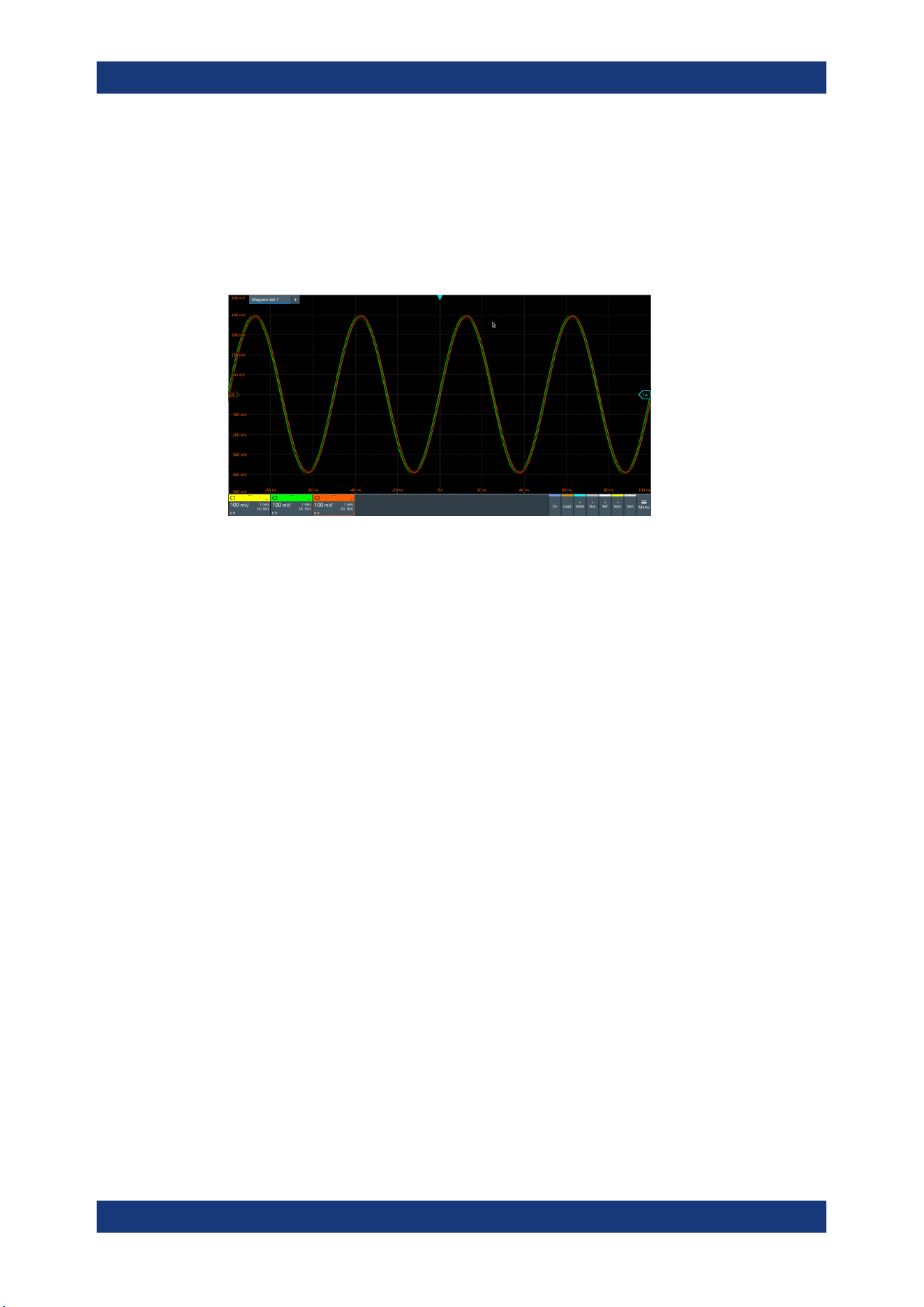
Remote control commands
R&S
®
MXO 5 Series
431User Manual 1802.3369.02 ─ 02
●
Chapter 17.14.1, "Spectrum setup", on page 588
//Prepeare: 3 channel signals.
//Enable C1, C2 and C3.
CHAN1:STAT 1
CHAN2:STAT 1
CHAN3:STAT 1
//Create new diagrams for C2 and C3.
//Assign sources C2 and C3 to these diagrams.
LAY:DIAG2:ENAB 1
LAY:DIAG2:SOUR C2
LAY:DIAG3:ENAB 1
LAY:DIAG3:SOUR C3
//Create new node (node 2) and assign new diagrams to that node
//Place C2 on top, C3 at bottom
LAY:NODE2:ENAB 1
LAY:NODE2:CHIL1:CONT:TYPE DIAG
LAY:NODE2:CHIL1:CONT:ID 2
LAY:NODE2:CHIL2:CONT:TYPE DIAG
LAY:NODE2:CHIL2:CONT:ID 3
LAY:NODE2:STYP VERT
//Insert node 2 into the base node (initial node)
//Diagram1 is initially located at child 1
LAY:NODE1:CHIL2:CONT:TYPE NODE
LAY:NODE1:CHIL2:CONT:ID 2
//Place both nodes side by side
LAY:NODE1:STYP HOR
Programming examples
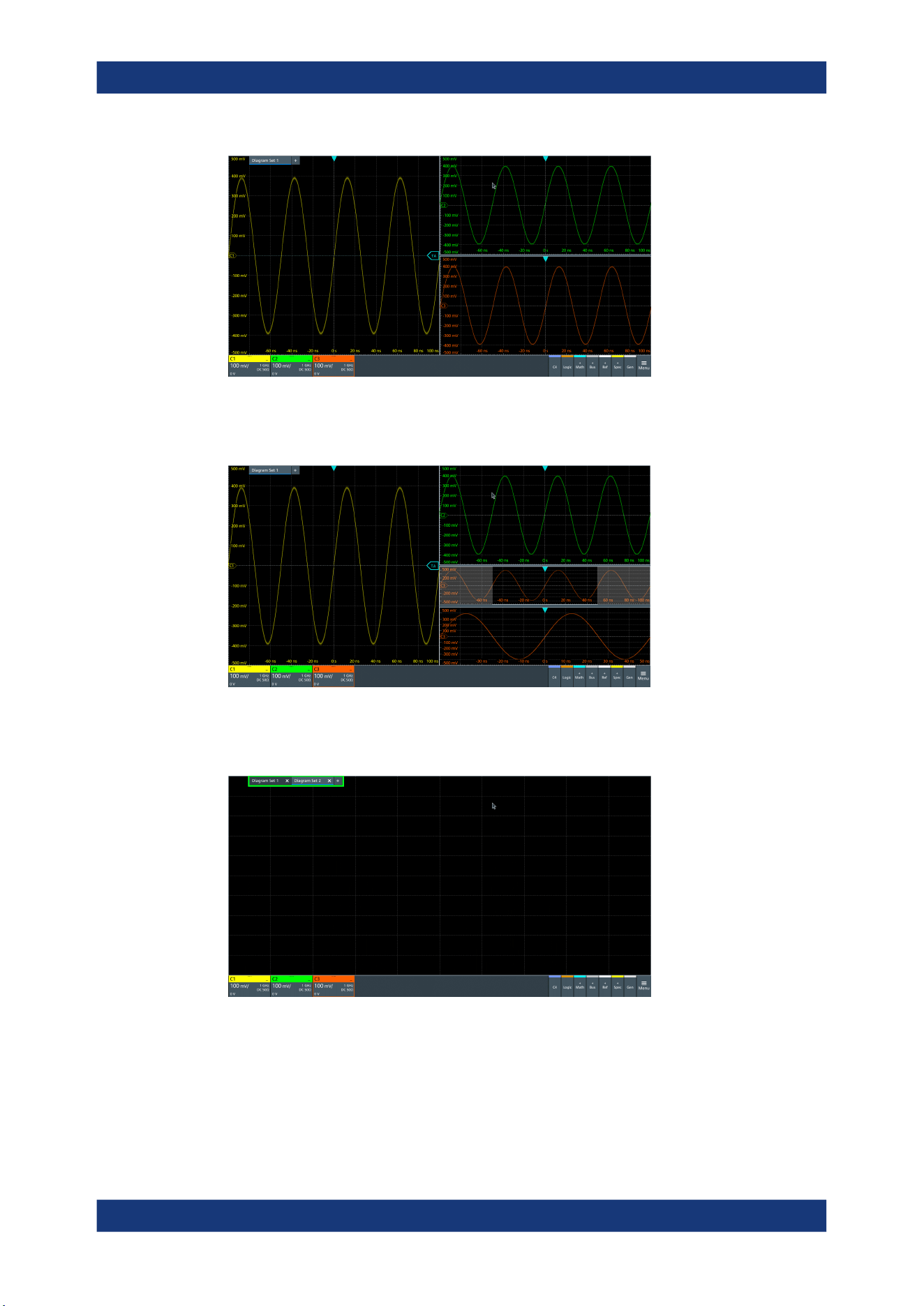
Remote control commands
R&S
®
MXO 5 Series
432User Manual 1802.3369.02 ─ 02
//Add zoom to C3. The zoom is located in diagram 3.
LAY:ZOOM:ENAB 1
LAY:ZOOM:SOUR 3
//Add a second layout with C1 and spectrum of C1.
//By default, the new layout is empty.
LAY2:ENAB 1
//Assign C1 to layout 2.
LAY2:DIAG1:SOUR C1
Programming examples
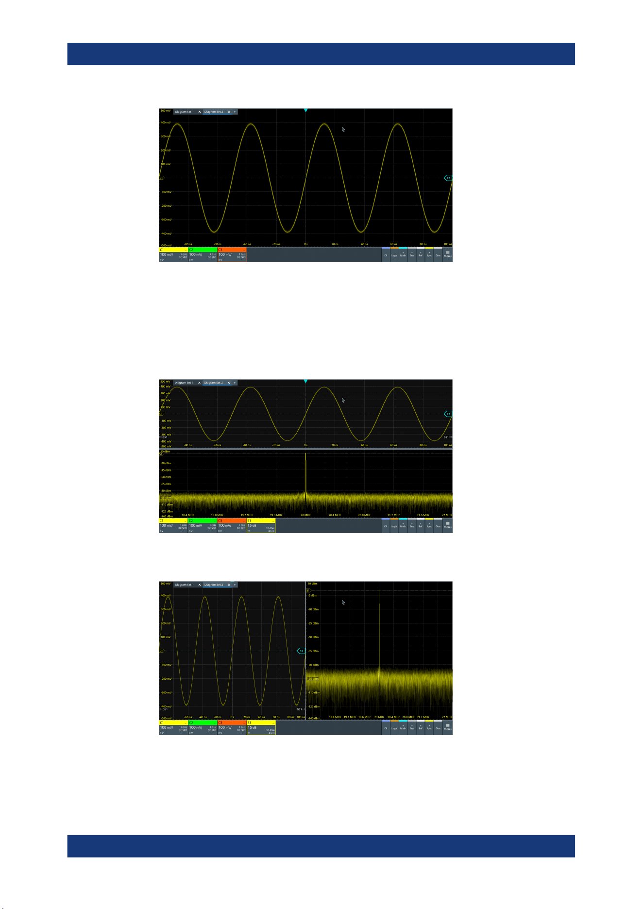
Remote control commands
R&S
®
MXO 5 Series
433User Manual 1802.3369.02 ─ 02
//Turn on spectrum of C1.
//By default, the spectrum is set below its analog source, and into the next
//free diagram (here diagram 2).
CALC:SPEC:STAT 1
CALC:SPEC:FREQ:CENT 20e6
CALC:SPEC:FREQ:SPAN 4e6
CALC:SPEC:FREQ:SCAL 15
//Set C1 and spectrum side by side by changing the split type.
LAY2:NODE1:STYP HOR
//Add zoom to spectrum. The zoom is located in layout 2, in diagram 2.
LAY2:ZOOM:ENAB 1
LAY2:ZOOM:SOUR 2
Programming examples
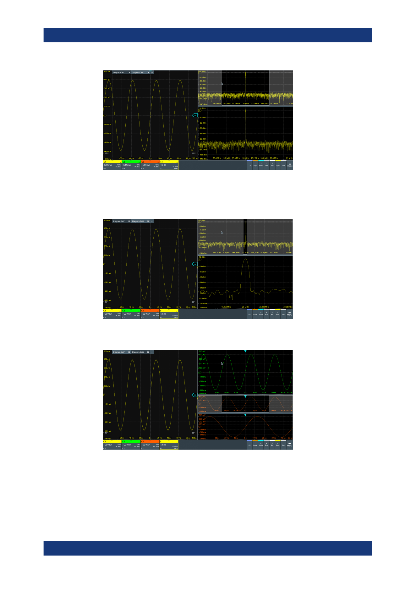
Remote control commands
R&S
®
MXO 5 Series
434User Manual 1802.3369.02 ─ 02
//Change zoom area.
LAY2:ZOOM:HOR:MODE REL
LAY2:ZOOM:HOR:REL:START 48
LAY2:ZOOM:HOR:REL:STOP 52
//Switch back to first layout (diagram set 1).
LAY1:SACT
17.4.2 Saving screenshots to file
The example saves three display images in png format to the files Print.png,
Print_001.png, and Print_002.png on USB flash drive in the directory /run/
media/usb/. To get a correct screenshot, turn on the display first.
Programming examples

Remote control commands
R&S
®
MXO 5 Series
435User Manual 1802.3369.02 ─ 02
Command description in: Chapter 17.11.6, "Screenshots", on page 554.
In the following example *OPC prevents overlapping execution of asynchronous com-
mands.
► Connect a USB flash drive to the instrument.
SYST:DISP:UPD ON
HCOP:DEST 'MMEM'
HCOP:DEV:LANG PNG
*OPC?
MMEM:NAME '/run/media/usb/'
HCOP:IMMediate; *OPC?
HCOP:IMM:NEXT; *OPC?
HCOP:IMM:NEXT; *OPC?
17.4.3 Data transfer in roll mode
The example shows the effects of EXPort:WAVeform:SCOPe and ACQuire:
ROLLmode:OSCapture in roll mode.
Sample rate mode and record length mode are set to AUTO, and the record length is
10 M points.
ACQuire:SRATe:MODE AUTO
ACQuire:POINts:MODE AUTO
ACQuire:POINts?
--> 10000000
ACQuire:ROLLmode:OSCapture OFF
CHANnel1:DATA:HEADer?
--> -5,4.999999,10000000,1 //10 M points of data are transferred
ACQuire:ROLLmode:OSCapture ON
EXPort:WAVeform:SCOPe DISP //Export of the displayed data
CHANnel1:DATA:HEADer?
--> -5,4.999999,10000000,1 //10 M points of data are transferred
EXPort:WAVeform:SCOPe ALL //Export of all data
CHANnel1:DATA:HEADer?
--> -31.702346,4.99999999,36702346,1 //36.7 M points of data are transferred
17.5 Common commands
Common commands are described in the IEEE 488.2 (IEC 625-2) standard. These
commands have the same effect and are employed in the same way on different devi-
ces. The headers of these commands consist of "*" followed by three letters. Many
common commands are related to the Status Reporting System.
Available common commands:
Common commands

Remote control commands
R&S
®
MXO 5 Series
436User Manual 1802.3369.02 ─ 02
*CAL?...........................................................................................................................436
*CLS.............................................................................................................................436
*IDN?............................................................................................................................436
*OPC............................................................................................................................437
*OPT?...........................................................................................................................437
*RCL.............................................................................................................................437
*RST.............................................................................................................................437
*SAV.............................................................................................................................438
*SRE............................................................................................................................ 438
*STB?...........................................................................................................................438
*TRG............................................................................................................................ 438
*WAI............................................................................................................................. 438
*CAL?
Starts a self-alignment of the instrument, and then queries a status response. Return
values ≠ 0 indicate an error.
Return values:
<State> 0: no error
1: alignment failed
2: not aligned, e.g. init
3: device needs longer warmup time before selfalignment can
start
4: input signal connected during selfalignment
Usage: Query only
*CLS
Clear status
Sets the status byte (STB), the standard event register (ESR) and the EVENt part of
the QUEStionable and the OPERation registers to zero. The command does not
alter the mask and transition parts of the registers. It clears the output buffer.
Usage:
Setting only
*IDN?
Identification
Returns the instrument identification.
Return values:
<ID> "Rohde&Schwarz,<device type>,<part number>/<serial num-
ber>,<firmware version>"
Example:
Rohde&Schwarz,MXO5,1802.1008k08/100222,2.00.0.2
Model assignment:
Usage: Query only
Common commands

Remote control commands
R&S
®
MXO 5 Series
437User Manual 1802.3369.02 ─ 02
Manual operation: See "Instrument" on page 70
*OPC
Operation complete
Sets bit 0 in the event status register when all preceding commands have been execu-
ted. This bit can be used to initiate a service request. The query writes a "1" into the
output buffer when all preceding commands have been executed, which is useful for
command synchronization.
*OPT?
Option identification query
Queries the options included in the instrument. For a list of all available options and
their description, refer to the data sheet.
Return values:
<Options> The query returns a list of options. The options are returned at
fixed positions in a comma-separated string. A zero is returned
for options that are not installed.
Usage: Query only
*RCL <Number>
Recall
Loads the instrument settings from an intermediate memory identified by the specified
number. The instrument settings can be stored to this memory using the command
*SAV with the associated number.
The stored instrument settings do not include waveform generator settings.
It also activates the instrument settings which are stored in a file and loaded using
MMEMory:LOAD:STATe.
*RST
Reset
Sets the instrument to a default status. The default settings are indicated in the
description of commands. Default settings are fixed, they are not changed by user-
defined preset.
The command does not affect the waveform generator settings. To reset the generator,
use WGENerator<wg>:PRESet.
Usage:
Setting only
Common commands

Remote control commands
R&S
®
MXO 5 Series
438User Manual 1802.3369.02 ─ 02
*SAV <Number>
Save
Stores the current instrument settings under the specified number in an intermediate
memory. The settings can be recalled using the command *RCL with the associated
number.
Waveform generator settings are not included.
To transfer the stored instrument settings to a file, use MMEMory:STORe:STATe.
*SRE <Contents>
Service request enable
Sets the service request enable register to the indicated value. This command deter-
mines under which conditions a service request is triggered.
Parameters:
<Contents> Contents of the service request enable register in decimal form.
Bit 6 (MSS mask bit) is always 0.
Range: 0 to 255
*STB?
Status byte query
Reads the contents of the status byte in decimal form.
Usage:
Query only
*TRG
Trigger
Triggers all actions waiting for a trigger event. In particular, *TRG generates a manual
trigger signal. This common command complements the commands of the TRIGger
subsystem.
*TRG corresponds to the INITiate:IMMediate command.
Usage:
Event
*WAI
Wait to continue
Prevents servicing of the subsequent commands until all preceding commands have
been executed and all signals have settled (see also command synchronization and
*OPC).
Usage:
Event
Common commands

Remote control commands
R&S
®
MXO 5 Series
439User Manual 1802.3369.02 ─ 02
17.6 General remote settings
This chapter describes commands that affect many other remote commands in differ-
ent applications of the instrument.
FORMat[:DATA]............................................................................................................. 439
FORMat:BPATtern..........................................................................................................440
SYSTem:DISPlay:UPDate...............................................................................................440
SYSTem:DISPlay:MESSage:STATe................................................................................. 440
SYSTem:DISPlay:MESSage[:TEXT].................................................................................441
FORMat[:DATA] [<Format>],[<Length>]
FORMat[:DATA]? [<Format>]
Selects the data type that is used for transmission of data from analog channels, math
and reference waveforms, and some measurement results from the instrument to the
controlling computer.
Setting parameters:
<Length> *RST: ASCii
Parameters for setting and query:
<Format> ASCii | REAL | INT
ASCii
Data values are returned in ASCII format as a list of comma-
separated values in floating point format. The length can be
omitted. It is 0 which means that the instrument selects the num-
ber of digits to be returned. The query returns both values (ASC,
0).
REAL,32
The data is stored as binary data (Definite Length Block Data
according to IEEE 488.2). Each waveform value is formatted in
32-Bit IEEE 754 Floating Point Format.
The schema of the result string is as follows:
#41024<value1><value2>…<value n> with:
#4 = number of digits (= 4 in the example) of the following num-
ber
1024 = number of following data bytes (= 1024 in the example)
<value> = 4-byte floating point values
For large data (≥ 1 GB), the result string starts with "#(data
length)". The number inside the parentheses indicates the real
data length in bytes.
INT,8 | INT,16 | INT,32
Signed integer data with length 8 bit, 16 bit, or 32 bit.
The result string has the same schema as the REAL format.
Fot INT,16 you can set the byte order using the command.
For digital channel data, math and histogram data, INT formats
are not available.
General remote settings

Remote control commands
R&S
®
MXO 5 Series
440User Manual 1802.3369.02 ─ 02
Example:
FORMat:DATA REAL,32
FORMat:DATA?
REAL,32
Usage: SCPI confirmed
Asynchronous command
Manual operation: See "Transfer data format" on page 74
FORMat:BPATtern <BtPattFmt>
Sets the number format for remote bit pattern queries on serial protocols.
Parameters:
<BtPattFmt> DEC | HEX | OCT | BIN | ASCII | ASCii | STRG
*RST: HEX
Usage: Asynchronous command
Manual operation: See "Bit pattern format" on page 74
SYSTem:DISPlay:UPDate <DisplayUpdate>
Defines whether the display is updated while the instrument is in the remote state. If
the display is switched off, the normal GUI is replaced by a static image while the
instrument is in the remote state. Switching off the display can speed up the measure-
ment. This is the recommended state.
Parameters:
<DisplayUpdate> ON | OFF
ON| 1: Display is shown and updated during remote control.
OFF| 0: Display shows static image during remote control.
*RST: OFF
Example:
SYSTem:DISPlay:UPDate 1
Switch on the display update.
Usage: Asynchronous command
SYSTem:DISPlay:MESSage:STATe <DispMessSt>
Enables and disables the display of an additional text in remote control.
To define the text, use SYSTem:DISPlay:MESSage[:TEXT].
Parameters:
<DispMessSt> ON | OFF
*RST: OFF
Usage: Asynchronous command
General remote settings

Remote control commands
R&S
®
MXO 5 Series
441User Manual 1802.3369.02 ─ 02
SYSTem:DISPlay:MESSage[:TEXT] <DisplayMessage>
Defines an additional text that is displayed during remote control operation.
To enable the text display, use SYSTem:DISPlay:MESSage:STATe.
Parameters:
<DisplayMessage>
Usage: Asynchronous command
17.7 Instrument setup
● System.................................................................................................................. 441
● SmartGrid..............................................................................................................443
● Toolbar.................................................................................................................. 448
● Appearance...........................................................................................................449
● Display.................................................................................................................. 453
● Maintenance..........................................................................................................459
17.7.1 System
SYSTem:COMMunicate:NET[:HOSTname].......................................................................441
SYSTem:DATE.............................................................................................................. 441
SYSTem:EXIT................................................................................................................442
SYSTem:FW:FILepath.................................................................................................... 442
SYSTem:PRESet........................................................................................................... 442
SYSTem:SHUTdown...................................................................................................... 442
SYSTem:FW:STARt........................................................................................................443
SYSTem:TIME............................................................................................................... 443
SYSTem:COMMunicate:NET[:HOSTname] <Hostname>
Sets the host name of the instrument, which is required when configuring a network.
The query SYSTem:COMMunicate:NET:HOSTname? returns the currently defined
host name.
Parameters:
<Hostname> String parameter
Usage: Asynchronous command
Manual operation: See "Device name" on page 71
SYSTem:DATE <Year>,<Month>,<Day>
Sets the date of the internal calendar.
Instrument setup

Remote control commands
R&S
®
MXO 5 Series
442User Manual 1802.3369.02 ─ 02
Parameters:
<Year> Year, to be entered as a four-digit number (including the century
and millennium information)
Range: 2012 to 2099
Increment: 1
*RST: 2012
<Month> Month, 1 (January) to 12 (December)
Range: 1 to 12
Increment: 1
*RST: 1
<Day> Day, 1 to the maximum number of days in the specified month
Range: 1 to 31
Increment: 1
*RST: 1
Example:
SYSTem:DATE?
Returned value: 2022,09,28
Usage: Asynchronous command
SYSTem:EXIT
Starts the shutdown of the firmware.
Usage:
Setting only
Asynchronous command
SYSTem:FW:FILepath <FilePath>
Sets the path and the filename of the firmware installation file.
Parameters:
<FilePath> String with path and filename
Usage: SCPI confirmed
Asynchronous command
SYSTem:PRESet
Resets the instrument to the default state, has the same effect as *RST.
Usage:
Setting only
SCPI confirmed
Asynchronous command
Manual operation: See "Factory preset" on page 90
SYSTem:SHUTdown
Starts the shutdown of the instrument (firmware and operating system).
Instrument setup

Remote control commands
R&S
®
MXO 5 Series
443User Manual 1802.3369.02 ─ 02
Usage: Setting only
Asynchronous command
SYSTem:FW:STARt
Starts the firmware update. Before starting, make sure that the correct path is set with
SYSTem:FW:FILepath.
Usage: Event
SCPI confirmed
Asynchronous command
SYSTem:TIME
<Hours>,<Minutes>,<Seconds>
Returns the current time of the clock.
Parameters:
<Hours> Range: 0 to 24
Increment: 1
*RST: 1
<Minutes> Range: 0 to 59
Increment: 1
*RST: 1
<Seconds> Range: 0 to 59
Increment: 1
*RST: 1
Usage: Asynchronous command
17.7.2 SmartGrid
The following LAYout commands configure the SmartGrid. In manual operation, you
configure the SmartGrid by drag and drop.
Table 17-1: Terms and definitions of SmartGrid configuration
Term Definition
Layout A layout is a SmartGrid configuration. Several configurations can exist but only one
configuration is active.
By default, SmartGrid configurations named "Diagram Set" on the display.
Children A child is an area where data (data table, result table) or waveforms (diagram) are dis-
played. Also a node can be a child (nested node).
Node A node consists of one or two children. A node is created with one child that has con-
tent.
Diagram A diagram displays waveforms, the graphical visualization of data.
Instrument setup

Remote control commands
R&S
®
MXO 5 Series
444User Manual 1802.3369.02 ─ 02
LAYout<ly>:COUNt?.......................................................................................................444
LAYout<ly>[:ENABle]......................................................................................................444
LAYout<ly>:ACTive.........................................................................................................444
LAYout<ly>:SACTive...................................................................................................... 445
LAYout<ly>:LABel.......................................................................................................... 445
LAYout<ly>:DIAGram<da>:COUNt?................................................................................. 445
LAYout<ly>:DIAGram<da>[:ENABle]................................................................................ 445
LAYout<ly>:DIAGram<da>:SOURce.................................................................................446
LAYout<ly>:DIAGram<da>:LABel.....................................................................................446
LAYout<ly>:NODE<no>:COUNt?..................................................................................... 446
LAYout<ly>:NODE<no>[:ENABle].................................................................................... 447
LAYout<ly>:NODE<no>:CHILdren<o>:CONTent<p>:ID...................................................... 447
LAYout<ly>:NODE<no>:CHILdren<o>:CONTent<p>:TYPE.................................................447
LAYout<ly>:NODE<no>:RATio.........................................................................................448
LAYout<ly>:NODE<no>:STYPe....................................................................................... 448
LAYout<ly>:COUNt?
Returns the number of available layouts, i.e. SmartGrid configurations. By default, they
named "Diagram Set" on the display.
Suffix:
<ly>
.
Irrelevant, omit the suffix.
Return values:
<Count> Number of SmartGrid configurations
Usage: Query only
Asynchronous command
LAYout<ly>[:ENABle] <State>
Creates a new SmartGrid configuration and sets it active.
Suffix:
<ly>
.
1...8, index of the SmartGrid layout
Parameters:
<State> ON | OFF
Example: See Chapter 17.4.1, "SmartGrid layout with zoom", on page 430.
Usage: Asynchronous command
LAYout<ly>:ACTive <ActiveKey>
Sets the active SmartGrid configuration. The query returns the index of the active lay-
out.
Suffix:
<ly>
.
Irrelevant, omit the suffix.
Instrument setup

Remote control commands
R&S
®
MXO 5 Series
445User Manual 1802.3369.02 ─ 02
Parameters:
<ActiveKey> Index of the active layout
Usage: Asynchronous command
LAYout<ly>:SACTive
Activates the specified SmartGrid configuration. The command has the same effect as
LAYout<ly>:ACTive but it has no query, and the active layout is specified by the suf-
fix.
Suffix:
<ly>
.
1...8, index of the SmartGrid layout
Example: See Chapter 17.4.1, "SmartGrid layout with zoom", on page 430.
Usage: Setting only
Asynchronous command
LAYout<ly>:LABel <Label>
Defines a name for the specified layout (SmartGrid configuration).
Suffix:
<ly>
.
1...8, index of the SmartGrid layout
Parameters:
<Label> String with the layout name
Usage: Asynchronous command
LAYout<ly>:DIAGram<da>:COUNt?
Returns the number of diagrams in a specified layout.
Suffix:
<ly>
.
1...8, index of the SmartGrid layout
<da> Irrelevant, omit the suffix.
Return values:
<Count> Number of diagrams
Usage: Query only
Asynchronous command
LAYout<ly>:DIAGram<da>[:ENABle] <State>
Creates and displays a specified diagram in a specified layout. OFF deletes the dia-
gram.
Suffix:
<ly>
.
1...8, index of the SmartGrid layout
Instrument setup

Remote control commands
R&S
®
MXO 5 Series
446User Manual 1802.3369.02 ─ 02
<da> 1...8, index of the diagram
Parameters:
<State> ON | OFF
Example: See Chapter 17.4.1, "SmartGrid layout with zoom", on page 430.
Usage: Asynchronous command
LAYout<ly>:DIAGram<da>:SOURce <SignalKeys>
Assigns the waveforms to a diagram.
Suffix:
<ly>
.
1...8, index of the SmartGrid layout
<da> 1...8, index of the diagram
Parameters:
<SignalKeys> String with a comma-separated list of waveforms, e.g. "C1,
C2, M1"
Example: See Chapter 17.4.1, "SmartGrid layout with zoom", on page 430.
Usage: Asynchronous command
LAYout<ly>:DIAGram<da>:LABel <Label>
Defines a name for the specified diagram in a specified layout.
Suffix:
<ly>
.
1...8, index of the SmartGrid layout
<da> 1...8, index of the diagram
Parameters:
<Label> String with the diagram name
Usage: Asynchronous command
LAYout<ly>:NODE<no>:COUNt?
Returns the maximum number of nodes that can be defined. This number is the maxi-
mum value for the node suffix.
Suffix:
<ly>
.
1...8, index of the SmartGrid layout
<no> Irrelevant, omit the suffix.
Return values:
<Count> Maximum value for the node suffix
Usage: Query only
Asynchronous command
Instrument setup

Remote control commands
R&S
®
MXO 5 Series
447User Manual 1802.3369.02 ─ 02
LAYout<ly>:NODE<no>[:ENABle] <State>
Creates the specified node in the specified layout. OFF deletes the node and its chil-
dren.
The query returns whether the specified node exists (1) or not (0).
Suffix:
<ly>
.
1...8, index of the SmartGrid layout
<no> Index of the node
Parameters:
<State> ON | OFF
Example: See Chapter 17.4.1, "SmartGrid layout with zoom", on page 430.
Usage: Asynchronous command
LAYout<ly>:NODE<no>:CHILdren<o>:CONTent<p>:ID <ID>
Sets the content ID, the number of the specified content type.
For example, the "Diagram5" has Type=DIAGRAM and ID=5.
Suffix:
<ly>
.
1...8, index of the SmartGrid layout
<no> Index of the node
<o> 1 | 2, child index
<p> Irrelevant, omit the suffix.
Parameters:
<ID> Numeric value
Example: See Chapter 17.4.1, "SmartGrid layout with zoom", on page 430.
Usage: Asynchronous command
LAYout<ly>:NODE<no>:CHILdren<o>:CONTent<p>:TYPE <Type>
Sets the content type for a specified child in a specified node: diagram, result table,
another node, or empty.
For example, the "Diagram5" has Type=DIAGRAM and ID=5.
Suffix:
<ly>
.
1...8, index of the SmartGrid layout
<no> Index of the node
<o> 1 | 2, child index
<p> Irrelevant, omit the suffix.
Instrument setup

Remote control commands
R&S
®
MXO 5 Series
448User Manual 1802.3369.02 ─ 02
Parameters:
<Type> NONE | DIAG | DIAGRAM | RES | RESULT | NODE
DIAG = DIAGRAM, RES = RESULT
*RST: NONE
Example: See Chapter 17.4.1, "SmartGrid layout with zoom", on page 430.
Usage: Asynchronous command
LAYout<ly>:NODE<no>:RATio <SplitRatio>
Sets the size ratio of the two children in the specified node.
Suffix:
<ly>
.
1...8, index of the SmartGrid layout
<no> Index of the node
Parameters:
<SplitRatio> Size ratio of the children. 0.5 assigns 50% of the node size to
each child. 0.3 assigns 30% to child 1% and 70% to child 2.
Range: 0 to 1
Increment: 0.0001
*RST: 0.5
Usage: Asynchronous command
LAYout<ly>:NODE<no>:STYPe <SplitType>
Creates a second child (e.g. diagram) in the node if only one child exists, and sets the
splitting of the node. If two children exist, only the splitting is set.
Suffix:
<ly>
.
1...8, index of the SmartGrid layout
<no> Index of the node
Parameters:
<SplitType> HOR | HORIZONTAL | VERT | VERTICAL
HOR = HORIZONTAL, VERT = VERTICAL
*RST: NONE
Example: See Chapter 17.4.1, "SmartGrid layout with zoom", on page 430.
Usage: Asynchronous command
17.7.3 Toolbar
DISPlay:TOOLbar:COUNt?............................................................................................. 449
DISPlay:TOOLbar:DESelect............................................................................................449
DISPlay:TOOLbar:RESTore............................................................................................ 449
Instrument setup

Remote control commands
R&S
®
MXO 5 Series
449User Manual 1802.3369.02 ─ 02
DISPlay:TOOLbar:COUNt?
Returns the number of tools that are currently assigned to the toolbar.
Return values:
<ToolCount> Range: 0 to 100
Increment: 1
*RST: 8
Usage: Query only
Asynchronous command
DISPlay:TOOLbar:DESelect
Removes all tools from the toolbar.
Usage:
Setting only
SCPI confirmed
Asynchronous command
DISPlay:TOOLbar:RESTore
Resets the toolbar to the factory configuration.
Usage:
Setting only
SCPI confirmed
Asynchronous command
17.7.4 Appearance
● Waveform colors................................................................................................... 449
● Grid appearance................................................................................................... 451
● Dialog appearance................................................................................................452
● Peak list appearance.............................................................................................453
17.7.4.1 Waveform colors
DISPlay:COLor:SIGNal:CATalog?.................................................................................... 449
DISPlay:COLor:SIGNal:COLor........................................................................................ 450
DISPlay:COLor:SIGNal:ASSign....................................................................................... 450
DISPlay:COLor:SIGNal:USE........................................................................................... 450
DISPlay:COLor:SIGNal:CATalog?
Returns a comma-separated list of valid signal names. The signal names are needed
in other DISPlay:COLor commands to set the <Signal> parameter.
Usage:
Query only
Asynchronous command
Instrument setup

Remote control commands
R&S
®
MXO 5 Series
450User Manual 1802.3369.02 ─ 02
DISPlay:COLor:SIGNal:COLor <Signal>,<Value>
Sets the color of the selected waveform.
Parameters:
<Value> Decimal value of the ARGB color. Use the color dialog box on
the instrument to get the hex value of the color, and convert the
hex value to a decimal value.
0 is fully transparent black.
4278190080 (dec) = FF000000 (hex) is opaque black.
4294967295 (dec) = FFFFFFFF (hex) is opaque white.
To reset the color to its default, use
DISPlay:COLor:SIGNal:COLor <Signal>,DEF.
Setting parameters:
<Signal> Signal name as returned by DISPlay:COLor:SIGNal:
CATalog?.
Usage: Asynchronous command
Manual operation: See "Color" on page 79
DISPlay:COLor:SIGNal:ASSign <Signal>,<ColorTable>
Assigns a color table to the source waveform instead of a dedicated color.
Parameters:
<ColorTable> String with the name of the color table
Setting parameters:
<Signal> Signal name as returned by DISPlay:COLor:SIGNal:
CATalog?.
Usage: Asynchronous command
Manual operation: See "Assigned color table" on page 79
DISPlay:COLor:SIGNal:USE <Signal>,<State>
If enabled, the selected waveform is displayed according to its assigned color table.
If disabled, the selected color is displayed, and the intensity of the signal color varies
according to the cumulative occurrence of the values.
Parameters:
<State> ON | OFF
Setting parameters:
<Signal> Signal name as returned by DISPlay:COLor:SIGNal:
CATalog?.
Usage: Asynchronous command
Manual operation: See "Use color table" on page 79
Instrument setup

Remote control commands
R&S
®
MXO 5 Series
451User Manual 1802.3369.02 ─ 02
17.7.4.2 Grid appearance
DISPlay:DIAGram:CROSshair.........................................................................................451
DISPlay:DIAGram:FINegrid.............................................................................................451
DISPlay:DIAGram:GRID................................................................................................. 451
DISPlay:DIAGram:LABels...............................................................................................451
DISPlay:DIAGram:YFIXed.............................................................................................. 452
DISPlay:DIAGram:CROSshair <Crosshair>
If selected, a crosshair is displayed in the diagram area. A crosshair allows you to
select a specific data point by its coordinates.
Parameters:
<Crosshair> ON | OFF
*RST: ON
Usage: Asynchronous command
Manual operation: See "Show crosshair" on page 81
DISPlay:DIAGram:FINegrid <ShowFineScale>
If selected, the crosshair is displayed as a ruler with scale markers. If disabled, the
crosshair is shown as dashed lines.
Parameters:
<ShowFineScale> ON | OFF
*RST: ON
Usage: Asynchronous command
Manual operation: See "Show fine grid scale" on page 81
DISPlay:DIAGram:GRID <Show>
If selected, a grid is displayed in the diagram area. A grid helps you associate a spe-
cific data point to its exact value on the x- or y-axis.
Parameters:
<Show> ON | OFF
*RST: ON
Usage: Asynchronous command
Manual operation: See "Show grid" on page 81
DISPlay:DIAGram:LABels <ShowLabels>
If selected, labels mark values on the x- and y-axes in specified intervals in the dia-
gram.
Instrument setup

Remote control commands
R&S
®
MXO 5 Series
452User Manual 1802.3369.02 ─ 02
Parameters:
<ShowLabels> ON | OFF
*RST: ON
Usage: Asynchronous command
Manual operation: See "Show labels" on page 81
DISPlay:DIAGram:YFIXed <YGridFixed>
If enabled, the horizontal grid lines remain in their position when the position of the
curve is changed. Only the values at the grid lines are adapted.
Fixed horizontal grid lines correspond to the behavior of traditional oscilloscopes.
Parameters:
<YGridFixed> ON | OFF
*RST: ON
Usage: Asynchronous command
Manual operation: See "Keep Y-grid fixed" on page 82
17.7.4.3 Dialog appearance
DISPlay:DIALog:FONTsize..............................................................................................452
DISPlay:DIALog:TRANsparency......................................................................................452
DISPlay:RESult:FONTsize.............................................................................................. 453
DISPlay:DIALog:FONTsize <DialogFontSize>
Sets the font size of the text in dialog boxes.
Parameters:
<DialogFontSize> Range: 12 to 30
Increment: 1
*RST: 19
Usage: Asynchronous command
Manual operation: See "Font size (Dialog)" on page 82
DISPlay:DIALog:TRANsparency <DialogTransp>
Sets the transparency of the dialog box background. For high transparency values, you
can see the waveform display in the background, and possibly check the effect of the
changed setting. For lower transparency values, readability in the dialog box improves.
Parameters:
<DialogTransp> Range: 0 to 70
Increment: 1
*RST: 0
Instrument setup

Remote control commands
R&S
®
MXO 5 Series
453User Manual 1802.3369.02 ─ 02
Usage: Asynchronous command
Manual operation: See "Transparency (Dialog)" on page 83
DISPlay:RESult:FONTsize <ResultFontSize>
Sets the font size of the text in result tables.
Parameters:
<ResultFontSize> Range: 8 to 30
Increment: 1
*RST: 19
Usage: Asynchronous command
Manual operation: See "Font size (Result dialog)" on page 83
17.7.4.4
Peak list appearance
CALCulate:SPECtrum<sp>:PLISt:LABel:BORDer..............................................................453
CALCulate:SPECtrum<sp>:PLISt:LABel:BORDer <LabelBorder>
Defines the layout of the labels, full border or none.
Suffix:
<sp>
.
1...4, index of the spectrum
Parameters:
<LabelBorder> NOBorder | FULL
FULL: Full border
*RST: FULL
Usage: Asynchronous command
Manual operation: See "Frame type" on page 83
17.7.5 Display
● Persistence........................................................................................................... 453
● Signal.................................................................................................................... 455
● Backlight................................................................................................................455
● Clear results..........................................................................................................456
● Save/Recall...........................................................................................................456
17.7.5.1 Persistence
DISPlay:PERSistence:INFinite.........................................................................................454
DISPlay:PERSistence:RESet.......................................................................................... 454
DISPlay:PERSistence:TIME............................................................................................454
DISPlay:PERSistence[:STATe].........................................................................................454
Instrument setup

Remote control commands
R&S
®
MXO 5 Series
454User Manual 1802.3369.02 ─ 02
DISPlay:PERSistence:INFinite <State>
If infinite persistence is enabled, each new waveform point remains on the screen until
this option is disabled. Use infinite persistence to display rare events in the signal.
Parameters:
<State> ON | OFF
*RST: OFF
Usage: Asynchronous command
Manual operation: See "Infinite persistence" on page 85
DISPlay:PERSistence:RESet
Resets the display, removing persistent all waveform points.
Usage:
Setting only
Asynchronous command
Manual operation: See "Reset" on page 85
DISPlay:PERSistence:TIME <Time>
Sets a time factor that controls how long the waveforms points fade away from the dis-
play. Thus, the R&S MXO 5 emulates the persistence of analog phosphor screens.
Parameters:
<Time> Range: 0.05 to 50
Increment: 0.05
*RST: 0.05
Default unit: s
Usage: Asynchronous command
Manual operation: See "Time" on page 85
DISPlay:PERSistence[:STATe] <State>
If enabled, each new data point in the diagram area remains on the screen for the
duration defined using DISPlay:PERSistence:TIME, or as long as DISPlay:
PERSistence:INFinite is enabled.
If disabled, the signal value is only displayed as long as it actually occurs.
Parameters:
<State> ON | OFF
*RST: ON
Usage: Asynchronous command
Manual operation: See "Enable" on page 85
Instrument setup

Remote control commands
R&S
®
MXO 5 Series
455User Manual 1802.3369.02 ─ 02
17.7.5.2 Signal
DISPlay:INTensity.......................................................................................................... 455
DISPlay:DIAGram:STYLe............................................................................................... 455
DISPlay:INTensity <Intensity>
The intensity determines the strength of the waveform line in the diagram. Enter a per-
centage between 0 (not visible) and 100% (strong). The default value is 50%.
Parameters:
<Intensity> Range: 0 to 100
Increment: 1
*RST: 50
Default unit: %
Usage: Asynchronous command
Manual operation: See "Intensity" on page 86
DISPlay:DIAGram:STYLe <Style>
Selects the style in which the waveform is displayed.
Parameters:
<Style> VECTors | DOTS
VECTors
The individual data points are connected by a line.
DOTS
Only the individual data points are displayed.
*RST: VECTors
Usage: Asynchronous command
Manual operation: See "Waveform style" on page 86
17.7.5.3 Backlight
DISPlay:BACKlight[:BRIGtness].......................................................................................455
DISPlay:BACKlight:DIMMing........................................................................................... 456
DISPlay:BACKlight[:BRIGtness] <LCDIntensity>
Sets the background luminosity of the touchscreen.
Parameters:
<LCDIntensity> Range: 5 to 100
Increment: 1
*RST: 90
Default unit: %
Usage: Asynchronous command
Instrument setup

Remote control commands
R&S
®
MXO 5 Series
456User Manual 1802.3369.02 ─ 02
Manual operation: See "Brightness" on page 87
DISPlay:BACKlight:DIMMing <UsrActivityTout>
Selects a time, after which the monitor brightness is reduced, if the instrument was
inactive. Remote control of the instrument is also considered as an activity.
Parameters:
<UsrActivityTout> OFF | T1Minute | T2Minutes | T3Minutes | T5Minutes |
T10Minutes | T15Minutes | T20Minutes | T25Minutes |
T30Minutes | T45Minutes | T1Hour | T2Hours | T3Hours |
T4Hours
*RST: OFF
Usage: Asynchronous command
Manual operation: See "Dimm on user inactivity" on page 87
17.7.5.4 Clear results
DISPlay:CLR
Deletes all measurement results including all waveforms and statistics.
Usage:
Setting only
Asynchronous command
Manual operation: See "Clear" on page 58
17.7.5.5 Save/Recall
Autonaming
MMEMory:AUTonaming:PREFix...................................................................................... 456
MMEMory:AUTonaming:TIME......................................................................................... 456
MMEMory:AUTonaming:INDex........................................................................................ 456
MMEMory:AUSave:ENABle............................................................................................ 457
MMEMory:AUSave:INTerval............................................................................................457
MMEMory:AUTonaming:USERtext...................................................................................457
MMEMory:AUTonaming:DEFaultpath............................................................................... 458
MMEMory:AUTonaming:RESall....................................................................................... 458
MMEMory:AUTonaming:RESPath....................................................................................458
MMEMory:AUTonaming:TEXT.........................................................................................458
MMEMory:AUTonaming:PREFix <MainNmeStemSt>
MMEMory:AUTonaming:TIME <DateTime>
MMEMory:AUTonaming:INDex <NameIndex>
Includes or excludes the prefix/ date/time /index in the filename pattern for automatic
filename generation. This name is used as the default filename.
Instrument setup

Remote control commands
R&S
®
MXO 5 Series
457User Manual 1802.3369.02 ─ 02
The prefix indicates the type of data that is saved, for example, RefCurve, Settings.
Parameters:
<NameIndex> ON | OFF
*RST: ON
Usage: Asynchronous command
Manual operation: See "Index" on page 97
MMEMory:AUSave:ENABle <EnableAutosave>
Enables the automatic saving of the waveform. You can set the autosave interval with
MMEMory:AUSave:INTerval.
Parameters:
<EnableAutosave> ON | OFF
*RST: ON
Usage: Asynchronous command
Manual operation: See "Enable autosave" on page 97
MMEMory:AUSave:INTerval <AutosaveIntvl>
Defines the time interval for the automatic saving of the waveform, if MMEMory:
AUSave:ENABle is set to ON.
Parameters:
<AutosaveIntvl> Range: 1 to 360000
Increment: 1
*RST: 300
Default unit: s
Usage: Asynchronous command
Manual operation: See "Enable autosave" on page 97
MMEMory:AUTonaming:USERtext <NmeStringSt>
If enabled, inserts the specified user text after the prefix.
You can define the text with MMEMory:AUTonaming:TEXT.
Parameters:
<NmeStringSt> ON | OFF
*RST: OFF
Usage: Asynchronous command
Manual operation: See "User text" on page 96
Instrument setup

Remote control commands
R&S
®
MXO 5 Series
458User Manual 1802.3369.02 ─ 02
MMEMory:AUTonaming:DEFaultpath <Path>
Sets the path where data and settings files are stored. On the instrument, all user data
is written to home/storage/userData. You can create subfolders in this folder.
Parameters:
<Path> String parameter
Usage: Asynchronous command
Manual operation: See "Default path for all file operations" on page 97
MMEMory:AUTonaming:RESall
Resets all autonaming settings to the default value, including the path.
Usage:
Setting only
Asynchronous command
Manual operation: See "Reset path" on page 97
MMEMory:AUTonaming:RESPath
Resets the path for file operations to the factory default path.
Usage:
Setting only
Asynchronous command
Manual operation: See "Reset path" on page 97
MMEMory:AUTonaming:TEXT <NameString>
Defines a text that can be included in the autonaming pattern.
Parameters:
<NameString> String parameter
Usage: Asynchronous command
Manual operation: See "User text" on page 96
CSV export
EXPort:RESult:DELimiter <Delimiter>
Selects the list separator symbol from a list. Available are semicolon, comma, space,
tab and colon.
Parameters:
<Delimiter> SEMICOLON | COMMA | SPACE | TAB | COLON
*RST: COMMA
Manual operation: See "CSV delimiter" on page 98
Instrument setup

Remote control commands
R&S
®
MXO 5 Series
459User Manual 1802.3369.02 ─ 02
17.7.6 Maintenance
CALibration:DATE?........................................................................................................ 459
CALibration:TIME?.........................................................................................................459
CALibration:RESult?.......................................................................................................459
SERVice:REPort............................................................................................................ 459
SYSTem:APUP..............................................................................................................460
CALibration:DATE?
Returns the date of the last self-alignment.
Return values:
<Date>
Usage: Query only
Asynchronous command
Manual operation: See "Date, Time, Overall alignment state" on page 93
CALibration:TIME?
Returns the time of the last self-alignment.
Return values:
<Time>
Usage: Query only
Asynchronous command
Manual operation: See "Date, Time, Overall alignment state" on page 93
CALibration:RESult?
Returns the result of the last self-alignment and the current alignment status. In remote
mode, *CAL? provides more detailed information.
Return values:
<ResultState> PASSed | FAILed | NOALigndata
*RST: FAILed
Usage: Query only
Asynchronous command
Manual operation: See "Date, Time, Overall alignment state" on page 93
SERVice:REPort
Creates a service report.
The service report is a ZIP file with a complete bug report, all relevant setup informa-
tion, reporting and log files, alignment files, and the instrument configuration.
Instrument setup

Remote control commands
R&S
®
MXO 5 Series
460User Manual 1802.3369.02 ─ 02
If a USB flash drive is connected, the report is saved on the USB flash drive. Other-
wise, the report is saved in the user data folder /home/storage/userData.
Usage: Event
Asynchronous command
Manual operation: See "Create report" on page 95
SYSTem:APUP <AutoPowerUp>
If enabled, the instrument powers up automatically when it is connected to the mains
voltage.
Parameters:
<AutoPowerUp> ON | OFF
*RST: ON
Usage: Asynchronous command
Manual operation: See "Auto power up" on page 94
17.8 Acquisition and setup
17.8.1 Starting and stopping acquisition
RUNCont...................................................................................................................... 460
RUN............................................................................................................................. 460
RUNSingle.................................................................................................................... 460
SINGle..........................................................................................................................460
STOP........................................................................................................................... 461
RUNCont
RUN
Starts the continuous acquisition.
Usage:
Setting only
Asynchronous command
Manual operation: See "Run/Stop" on page 107
RUNSingle
SINGle
Starts a defined number of acquisition cycles. The number of cycles is set with
ACQuire:COUNt.
Usage:
Setting only
Asynchronous command
Acquisition and setup

Remote control commands
R&S
®
MXO 5 Series
461User Manual 1802.3369.02 ─ 02
Manual operation: See "Run Single" on page 107
STOP
Stops the running acquisition.
Usage: Event
Asynchronous command
Manual operation: See "Run/Stop" on page 107
17.8.2 Horizontal setup
AUToscale.....................................................................................................................461
TIMebase:SCALe...........................................................................................................461
TIMebase:RANGe..........................................................................................................461
TIMebase:DIVisions?......................................................................................................462
TIMebase:HORizontal:POSition.......................................................................................462
TIMebase:REFerence.....................................................................................................462
AUToscale
Performs an autoset process: analyzes the enabled channel signals, and obtains
appropriate horizontal, vertical, and trigger settings to display stable waveforms.
Rohde & Schwarz does not recommend using the autoset in remote control. To adjust
the oscilloscope remotely, especially for automated testing applications, use the
remote commands that adjust the horizontal, vertical and trigger settings.
Usage:
Event
Asynchronous command
TIMebase:SCALe <TimebaseScale>
Sets the horizontal scale, the time per division, for all waveforms in the time domain,
for example, channel and math waveforms.
Parameters:
<TimebaseScale> Range: 200E-12 to 10E3
Increment: 1E-12
*RST: 20E-9
Default unit: s/div
Usage: Asynchronous command
Manual operation: See "Time scale" on page 101
TIMebase:RANGe <TimebaseRange>
Sets the time of one acquisition, which is the time across the 10 divisions of the dia-
gram: Acquisition time = Time scale * 10 divisions.
Acquisition and setup

Remote control commands
R&S
®
MXO 5 Series
462User Manual 1802.3369.02 ─ 02
Parameters:
<TimebaseRange> Range: Device specific to Device specific
Increment: 1E-12
*RST: Device specific
Default unit: s
Usage: Asynchronous command
Manual operation: See "Timebase range" on page 101
TIMebase:DIVisions?
Returns the number of horizontal divisions on the screen. The number cannot be
changed.
Return values:
<HorizDivCnt> *RST: 10
Usage: Query only
Asynchronous command
TIMebase:HORizontal:POSition <Position>
Defines the time distance between the reference point and the trigger point, which is
the zero point of the diagram. The horizontal position is also known as trigger offset.
Parameters:
<Position> Range: Device specific to 1E+26
Increment: 1E-12
*RST: 0
Default unit: s
Usage: Asynchronous command
Manual operation: See "Position" on page 101
TIMebase:REFerence <RescaleCtrPos>
Sets the position of the reference point in % of the screen. It defines which part of the
waveform is shown.
Parameters:
<RescaleCtrPos> Range: 0 to 100
Increment: 1
*RST: 50
Default unit: %
Usage: Asynchronous command
Manual operation: See "Reference point" on page 102
Acquisition and setup

Remote control commands
R&S
®
MXO 5 Series
463User Manual 1802.3369.02 ─ 02
17.8.3 Roll mode
TIMebase:ROLL:ENABle................................................................................................ 463
TIMebase:ROLL:MTIMe..................................................................................................463
ACQuire:ROLLmode:OSCapture..................................................................................... 463
ACQuire:ROLLmode:POINts?......................................................................................... 464
TIMebase:ROLL:STATe?.................................................................................................464
TIMebase:ROLL:ENABle <Mode>
Selects, if the roll mode is set automatically by the instrument or if it is turned off.
Parameters:
<Mode> AUTO | OFF
*RST: AUTO
Usage: Asynchronous command
Manual operation: See "Mode" on page 103
TIMebase:ROLL:MTIMe <MinAcquTime>
Sets the minimum acquisition time for automatic start of the roll mode.
Parameters:
<MinAcquTime> Range: 0.5 to 100000
Increment: 1
*RST: 2
Default unit: s
Usage: Asynchronous command
Manual operation: See "Start roll time" on page 103
ACQuire:ROLLmode:OSCapture <OffScreenCapture>
If enabled, the analyzable waveform in roll mode is extended. Samples that arrive the
left edge of the display are kept, they are moved to the unvisible area on the left.
Parameters:
<OffScreenCapture> ON | OFF
*RST: OFF
Example: See Chapter 17.4.3, "Data transfer in roll mode", on page 435.
Usage: Asynchronous command
Manual operation: See "Off screen capture" on page 103
Acquisition and setup

Remote control commands
R&S
®
MXO 5 Series
464User Manual 1802.3369.02 ─ 02
ACQuire:ROLLmode:POINts?
Returns the record length of the roll mode. In roll mode, the complete record is always
captured, independently of the displayed waveform. To process and analyze the com-
plete roll waveform, enable ACQuire:ROLLmode:OSCapture.
Return values:
<RecordLength> Range: 0 to 18446744073709551615
Increment: 1
*RST: 0
Default unit: pts
Usage: Query only
Asynchronous command
Manual operation: See "Off screen capture" on page 103
TIMebase:ROLL:STATe?
Returns the status of the roll mode.
Return values:
<State> ON | OFF
*RST: OFF
Usage: Query only
Asynchronous command
Manual operation: See "Mode" on page 103
17.8.4 Vertical setup
The channel suffix <ch> selects the input channel that is affected by the command.
CHANnel<ch>:STATe..................................................................................................... 464
CHANnel<ch>:SCALe.................................................................................................... 465
CHANnel<ch>:RANGe................................................................................................... 465
CHANnel<ch>:OFFSet................................................................................................... 465
CHANnel<ch>:POSition..................................................................................................466
CHANnel<ch>:COUPling................................................................................................ 466
CHANnel<ch>:INVert......................................................................................................467
CHANnel<ch>:SKEW:TIME.............................................................................................467
CHANnel<ch>:BANDwidth.............................................................................................. 468
CHANnel<ch>:EATScale................................................................................................ 468
CHANnel<ch>:EATTenuation...........................................................................................468
CHANnel<ch>:IMPedance.............................................................................................. 469
CHANnel<ch>:STATe <State>
Switches the selected channel signal on or off.
Acquisition and setup

Remote control commands
R&S
®
MXO 5 Series
465User Manual 1802.3369.02 ─ 02
Suffix:
<ch>
.
1 to 8, depending on instrument model. Index of the analog
channel.
Parameters:
<State> ON | OFF
*RST: OFF
Usage: Asynchronous command
Manual operation: See "Show channel" on page 115
CHANnel<ch>:SCALe <Scale>
Sets the vertical scale, which defines the displayed amplitude of the selected wave-
form.
Suffix:
<ch>
.
1 to 8, depending on instrument model. Index of the analog
channel.
Parameters:
<Scale> Range: 0.001 to 1
Increment: 0.001
*RST: 0.05
Default unit: Depends on the connected probe
Usage: Asynchronous command
Manual operation: See "[Scale]" on page 39
CHANnel<ch>:RANGe <Range>
Sets the voltage range across the 10 vertical divisions of the diagram. The command is
an alternative to CHANnel<ch>:SCALe.
Suffix:
<ch>
.
1 to 8, depending on instrument model. Index of the analog
channel.
Parameters:
<Range> Range: 0.01 to 10
Increment: 0.01
*RST: 0.5
Default unit: V/div
Usage: Asynchronous command
CHANnel<ch>:OFFSet <Offset>
Sets the offset voltage, which corrects an offset-affected signal. The vertical center of
the selected channel is shifted by the offset value and the signal is repositioned within
the diagram.
Acquisition and setup

Remote control commands
R&S
®
MXO 5 Series
466User Manual 1802.3369.02 ─ 02
Suffix:
<ch>
.
1 to 8, depending on instrument model. Index of the analog
channel.
Parameters:
<Offset> Range: -1 to 1
Increment: 0.01
*RST: 0
Default unit: V
Usage: Asynchronous command
Manual operation: See "[Position]" on page 39
CHANnel<ch>:POSition <Position>
Moves the selected signal up or down in the diagram. While the offset sets a voltage,
position is a graphical setting given in divisions. The visual effect is the same as for off-
set.
Suffix:
<ch>
.
1 to 8, depending on instrument model. Index of the analog
channel.
Parameters:
<Position> Positive values move up the waveform, negative values move it
down.
Range: -5 to 5
Increment: 0.02
*RST: 0
Default unit: div
Usage: Asynchronous command
Manual operation: See "[Position]" on page 39
CHANnel<ch>:COUPling <Value>
Sets the connection of the channel signal, i.e. the input impedance (coupling) and a fil-
ter (termination). The command determines what part of the signal is used for wave-
form analysis and triggering.
Suffix:
<ch>
.
1 to 8, depending on instrument model. Index of the analog
channel.
Parameters:
<Value> DC | DCLimit | AC
DC
Connection with 50 Ω termination, passes both DC and AC com-
ponents of the signal.
Acquisition and setup

Remote control commands
R&S
®
MXO 5 Series
467User Manual 1802.3369.02 ─ 02
DCLimit
Connection with 1 MΩ termination, passes both DC and AC
components of the signal.
AC
Connection with 1 MΩ termination through DC capacitor,
removes DC and very low-frequency components. The wave-
form is centered on zero volts.
Usage: Asynchronous command
Manual operation: See "Coupling" on page 116
CHANnel<ch>:INVert
<InvertChannel>
Turns the inversion of the signal amplitude on or off. To invert means to reflect the volt-
age values of all signal components against the ground level.
Suffix:
<ch>
.
1 to 8, depending on instrument model. Index of the analog
channel.
Parameters:
<InvertChannel> ON | OFF
ON: inverted waveform
OFF: normal waveform
*RST: OFF
Usage: Asynchronous command
Manual operation: See "Invert channel" on page 116
CHANnel<ch>:SKEW:TIME <Offset>
Sets a skew value to compensate for the delay of the measurement setup or from the
circuit specifics that the instrument cannot compensate automatically. It affects only the
selected input channel.
Suffix:
<ch>
.
1 to 8, depending on instrument model. Index of the analog
channel.
Parameters:
<Offset> Range: -1E-07 to 1E-07
Increment: 1E-12
*RST: 0
Default unit: s
Usage: Asynchronous command
Manual operation: See "Skew" on page 117
Acquisition and setup

Remote control commands
R&S
®
MXO 5 Series
468User Manual 1802.3369.02 ─ 02
CHANnel<ch>:BANDwidth <BandwidthLimit>
Sets the bandwidth limit. The specified bandwidth indicates the range of frequencies
that the instrument can acquire and display accurately with less than 3 dB attenuation.
Frequencies above the limit are removed from the signal, and noise is reduced.
Suffix:
<ch>
.
1 to 8, depending on instrument model. Index of the analog
channel.
Parameters:
<BandwidthLimit> FULL | B2G | B1G5 | B1G | B700 | B500 | B350 | B200 | B100 |
B50 | B20
FULL
Sets the bandwidth to the maximum bandwidth of the instru-
ment. Bandwidth extension options are considered.
B700 | B500 | B350 | B200 | B100 | B50 | B20
Sets a bandwidth limit lower than the maximum. The number
indicates the bandwidth limit in MHz.
B1G5 | B1G
Sets the bandwidth limit to 1500 MHz or 1000 MHz if these val-
ues are lower than the maximum.
*RST:
FULL
Usage: Asynchronous command
Manual operation: See "Bandwidth" on page 117
CHANnel<ch>:EATScale <ExtAttScl>
Sets the attenuation scale for an external divider: linear or logarithmic.
Suffix:
<ch>
.
1 to 8, depending on instrument model. Index of the analog
channel.
Parameters:
<ExtAttScl> LIN | LOG
*RST: LIN
Usage: Asynchronous command
Manual operation: See "External Attenuation: Scale, Attenuation" on page 119
CHANnel<ch>:EATTenuation <ExtAtt>
Consider a voltage divider that is part of the DUT before the measuring point. The
external attenuation is included in the measurement, and the instrument shows the
results that would be measured before the divider. External attenuation can be used
with all probes.
Acquisition and setup

Remote control commands
R&S
®
MXO 5 Series
469User Manual 1802.3369.02 ─ 02
Suffix:
<ch>
.
1 to 8, depending on instrument model. Index of the analog
channel.
Parameters:
<ExtAtt> Values depend on the selected scale (CHANnel<ch>:
EATScale on page 468) and the unit of the waveform. See
"External Attenuation: Scale, Attenuation" on page 119. Limits
below are for linear scale.
Range: 0.005 to 1000000
Increment: 0.01
*RST: 1
Usage: Asynchronous command
Manual operation: See "External Attenuation: Scale, Attenuation" on page 119
CHANnel<ch>:IMPedance
<Impedance>
Sets the impedance of the connected probe for power calculations and measurements.
Suffix:
<ch>
.
1 to 8, depending on instrument model. Index of the analog
channel.
Parameters:
<Impedance> Range: 0.1 to 100000
Increment: 1
*RST: 50
Default unit: Ω
Usage: Asynchronous command
Manual operation: See "Impedance" on page 119
17.8.5 Waveform data export
To set the export data format, see FORMat[:DATA].
CHANnel<ch>[:WAVeform<wf>]:DATA:HEADer?............................................................... 469
CHANnel<ch>[:WAVeform<wf>]:DATA[:VALues]?.............................................................. 470
CHANnel<ch>[:WAVeform<wf>]:DATA:HEADer?
Returns the header of channel waveform data. The header contains attributes of the
waveform.
Table 17-2: Header data
Position Meaning Example
1 XStart in s -9.477E-008 = - 94,77 ns
2 XStop in s 9.477E-008 = 94,77 ns
Acquisition and setup

Remote control commands
R&S
®
MXO 5 Series
470User Manual 1802.3369.02 ─ 02
Position Meaning Example
3 Record length of the waveform in Samples 200000
4 Number of values per sample interval. For most
waveforms, the result is 1. For peak detect and
envelope waveforms, it is 2. If the number is 2, the
number of returned values is twice the number of
samples (record length).
1
Suffix:
<ch>
.
1 to 8, depending on instrument model. Index of the analog
channel.
<wf> 1, can be omitted
Example:
CHAN1:WAV1:DATA:HEAD?
-9.477E-008,9.477E-008,200000,1
Usage: Query only
Asynchronous command
CHANnel<ch>[:WAVeform<wf>]:DATA[:VALues]? [<Offset>],[<Length>]
Returns the data of the channel waveform points for transmission from the instrument
to the controlling computer. The data can be used in MATLAB, for example.
Without parameters, the complete waveform is retrieved. Using the offset and length
parameters, data can be retrieved in smaller portions, which makes the command
faster. If you send only one parameter, it is interpreted as offset, and the data is
retrieved from offset to the end of the waveform.
To set the export format, use FORMat[:DATA] on page 439.
Suffix:
<ch>
.
1 to 8, depending on instrument model. Index of the analog
channel.
<wf> 1, can be omitted
Query parameters:
<Offset> Number of offset waveform samples to be skipped.
Range: 0 to m. Limit: n + m <= record length
<Length> Number of waveform points to be retrieved.
Range: 1 to n. Limit: n + m <= record length
Return values:
<Data> List of values according to the format and content settings.
Example: Retrieve the complete channel 1 waveform, only Y-values:
FORM ASC
CHAN1:WAV1:DATA?
<-- -0.125000,-0.123016,-0.123016,-0.123016,-0.123016,-0.123016,...
Acquisition and setup

Remote control commands
R&S
®
MXO 5 Series
471User Manual 1802.3369.02 ─ 02
Example: Retrieve the first 10 values of the waveform:
CHANnel:WAVeform:DATA:VALues? 0,10
<-- -0.10079051554203,-0.098814234137535,-0.098814234137535,
-0.096837945282459,-0.094861663877964,-0.094861663877964,
-0.092885382473469,-0.090909093618393,-0.090909093618393,
-0.088932812213898
Example: Skip 5 samples and retrieve the next 5 samples:
CHANnel:WAVeform:DATA:VALues? 5,5
<-- -0.094861663877964,-0.092885382473469,-0.090909093618393,
-0.090909093618393,-0.088932812213898
Usage: Query only
Asynchronous command
17.8.6 Acquisition setup
ACQuire:AVAilable?........................................................................................................471
ACQuire:AVERage?....................................................................................................... 471
ACQuire:COUNt............................................................................................................ 472
ACQuire:CURRent?....................................................................................................... 472
ACQuire:INTerpolate...................................................................................................... 472
ACQuire:POINts[:VALue]................................................................................................ 473
ACQuire:POINts:ARATe?................................................................................................ 473
ACQuire:POINts:MAXimum.............................................................................................473
ACQuire:POINts:MODE..................................................................................................473
ACQuire:RESolution.......................................................................................................474
ACQuire:SRATe[:VALue].................................................................................................474
ACQuire:SRATe:MINimum.............................................................................................. 475
ACQuire:SRATe:MODE.................................................................................................. 475
ACQuire:SRReal............................................................................................................475
ACQuire:TYPE.............................................................................................................. 475
ACQuire:AVAilable?
Number of acquisitions that is saved in the memory and available for history viewing. It
is also the number of acquisitions in a fast segmentation acquisition series.
Return values:
<AcquisitionCount> Range: 0 to 4294967295
Increment: 1
*RST: 0
Usage: Query only
Asynchronous command
Manual operation: See "Available acqs" on page 174
ACQuire:AVERage?
Returns the current number of acquired waveforms that contribute to the average.
Acquisition and setup

Remote control commands
R&S
®
MXO 5 Series
472User Manual 1802.3369.02 ─ 02
Return values:
<CurrAverageCount> Range: 0 to 4294967295
Increment: 1
*RST: 0
Usage: Query only
Asynchronous command
Manual operation: See "Current Average count" on page 109
ACQuire:COUNt <MaxAcqCnt>
Sets the acquisition and average count, which has a double effect:
●
It sets the number of waveforms acquired with RUNSingle.
●
It defines the number of waveforms used to calculate the average waveform.
Parameters:
<MaxAcqCnt> Range: 1 to 16777215
Increment: 1
*RST: 1
Usage: Asynchronous command
Manual operation: See "N-single/Avg count" on page 108
ACQuire:CURRent?
Returns the current number of acquisitions that have been acquired.
Return values:
<CurrAcqCnt> Range: 0 to 18446744073709551615
Increment: 1
*RST: 0
Usage: Query only
Asynchronous command
ACQuire:INTerpolate <IntpolMd>
Selects the interpolation method.
Parameters:
<IntpolMd> LINear | SINX | SMHD
LINear
Linear interpolation between two adjacent sample points
SINX
Interpolation with a sin(x)/x function.
SMHD
Sample/Hold causes a histogram-like interpolation.
*RST: SINX
Acquisition and setup

Remote control commands
R&S
®
MXO 5 Series
473User Manual 1802.3369.02 ─ 02
Usage: Asynchronous command
Manual operation: See "Interpolation" on page 109
ACQuire:POINts[:VALue] <RecordLength>
Sets the record length in manual record length mode. In automatic record length mode,
it sets the maximum value of the record length for automatic calculation.
The record length is the number of waveform samples that are stored in one waveform
record after processing, including interpolation.
Parameters:
<RecordLength> Range: 1000 to Device specific
Increment: 2
*RST: 1000
Default unit: pts
Usage: Asynchronous command
Manual operation: See "Record length, Record length limit" on page 108
ACQuire:POINts:ARATe?
Returns the sample rate of the ADC, before waveform processing. The result is the
interleaved sample rate or the non-interleaved one, depending on the channel usage.
Return values:
<ADCSampleRate> Range: 5 Gsample/s (interleaved), 2,5 Gsample/s (non-
interleaved)
Default unit: Hz
Usage: Query only
Asynchronous command
ACQuire:POINts:MAXimum <RecLengthLimit>
Sets the maximum record length, if ACQuire:POINts:MODE is set to AUTO.
Parameters:
<RecLengthLimit> Range: 1000 to 800E+6
Increment: 2
*RST: 10E+6
Default unit: pts
Usage: Asynchronous command
ACQuire:POINts:MODE <RecLengthMode>
Selects the mode of the waveform record length adjustment.
Parameters:
<RecLengthMode> AUTO | MANual
Acquisition and setup

Remote control commands
R&S
®
MXO 5 Series
474User Manual 1802.3369.02 ─ 02
AUTO
Record length is determined automatically and changes due to
instrument internal adjustments.
MANual
The waveform record length is defined with ACQuire:
POINts[:VALue].
*RST: AUTO
Usage: Asynchronous command
Manual operation: See "RL mode" on page 108
ACQuire:RESolution
<Resolution>
Defines the time between two waveform samples in the waveform record. It considers
the processing of the captured samples including interpolation. A fine resolution with
low values produces a more precise waveform record.
The resolution is the reciprocal value of ACQuire:SRATe[:VALue].
Parameters:
<Resolution> Range: 1E-15 to Device specific
Increment: 1E-11
*RST: Device specific
Default unit: s
Usage: Asynchronous command
Manual operation: See "Resolution" on page 109
ACQuire:SRATe[:VALue] <SampleRate>
Sets the number of waveform points per second in manual sample rate mode. In auto-
matic sample rate mode, it sets the minimum value of the sample rate for automatic
calculation.
The sample rate considers the samples of the ADC, and the processing of the cap-
tured samples including interpolation.
The value takes effect if ACQuire:SRATe:MODE is set to MANual.
Parameters:
<SampleRate> Range: Device specific to Device specific
Increment: 1
*RST: Device specific
Default unit: Sa/s
Usage: Asynchronous command
Manual operation: See "Sample rate, Min. sample rate" on page 108
Acquisition and setup

Remote control commands
R&S
®
MXO 5 Series
475User Manual 1802.3369.02 ─ 02
ACQuire:SRATe:MINimum <SampleRateMin>
Sets the minimum sample rate, if ACQuire:SRATe:MODE is set to AUTO.
Parameters:
<SampleRateMin> Increment: 1
*RST: 2
Default unit: Sa/s
Usage: Asynchronous command
ACQuire:SRATe:MODE
<SampleRateMode>
Defines how the sample rate is set.
Parameters:
<SampleRateMode> AUTO | MANual
AUTO
Sample rate is determined automatically and changes due to
instrument internal adjustments.
MANual
The sample rate is defined with ACQuire:SRATe[:VALue].
*RST: AUTO
Usage: Asynchronous command
Manual operation: See "SR mode" on page 107
ACQuire:SRReal <HWSampleRate>
Returns the sample rate of the waveform after HW processing. Interpolation is not con-
sidered.
Parameters:
<HWSampleRate> Range: Device specific to ADC sample rate
Increment: 0
*RST: Device specific
Default unit: Sa/s
Usage: Asynchronous command
ACQuire:TYPE <AcqMd>
Sets how the waveform is built from the captured samples.
Parameters:
<AcqMd> SAMPle | PDETect | ENVelope | AVERage
*RST: SAMPle
Usage: Asynchronous command
Manual operation: See "Acquisition mode" on page 109
Acquisition and setup

Remote control commands
R&S
®
MXO 5 Series
476User Manual 1802.3369.02 ─ 02
17.8.7 Fast segmentation
ACQuire:SEGMented:STATe <State>
If fast segmentation is enabled, the acquisitions are performed as fast as possible,
without processing and displaying the waveforms. When acquisition has been stopped,
the data is processed and the latest waveform is displayed. Older waveforms are
stored in segments. You can display and analyze the segments using the history.
Parameters:
<State> ON | OFF
*RST: OFF
Usage: Asynchronous command
Manual operation: See "Fast segmentation" on page 111
ACQuire:SEGMented:MAX
<MaxAcqs>
If ON, the instrument acquires the maximum number of segments that can be stored in
the memory. The maximum number depends on the current sample rate and record
length settings.
If OFF, define the number of segments in a fast segmentation cycle with ACQuire:
COUNt.
Parameters:
<MaxAcqs> ON | OFF
*RST: OFF
Usage: Asynchronous command
Manual operation: See "Acquire maximum" on page 110
17.8.8 Probes
● Common probe settings........................................................................................476
● Settings for active voltage probes.........................................................................481
● Settings for current probes....................................................................................487
● Probe attributes.....................................................................................................489
17.8.8.1 Common probe settings
The probe suffix <ch> selects the input channel to which the probe is connected.
PROBe<ch>:SETup:ATTenuation[:AUTO]?....................................................................... 477
PROBe<ch>:SETup:ATTenuation:MANual........................................................................ 477
PROBe<ch>:SETup:ATTenuation:DEFProbe.....................................................................477
PROBe<ch>:SETup:ATTenuation:UNIT............................................................................ 478
PROBe<ch>:SETup:BANDwidth?.................................................................................... 478
PROBe<ch>:SETup:OFFSet:TOMean..............................................................................479
Acquisition and setup

Remote control commands
R&S
®
MXO 5 Series
477User Manual 1802.3369.02 ─ 02
PROBe<ch>:SETup:OFFSet:AZERo................................................................................479
PROBe<ch>:SETup:OFFSet:USEautozero....................................................................... 479
PROBe<ch>:SETup:NAME?........................................................................................... 480
PROBe<ch>:SETup:STATe?........................................................................................... 480
PROBe<ch>:SETup:TYPE?............................................................................................ 480
PROBe<ch>:SETup:ATTenuation[:AUTO]?
Returns the attenuation of a detected or predefined probe.
Suffix:
<ch>
.
1 to 8, depending on instrument model. Index of the analog
channel.
Return values:
<Attenuation> Range: 0.001 to 1000
Increment: 0.1
*RST: 1
Default unit: V/V
Usage: Query only
Asynchronous command
Manual operation: See "Manual attenuation" on page 121
PROBe<ch>:SETup:ATTenuation:MANual <Attenuation>
Sets the attenuation for an unknown probe.
Suffix:
<ch>
.
1 to 8, depending on instrument model. Index of the analog
channel.
Parameters:
<Attenuation> Range: 0.0001 to 10000
Increment: 0.1
*RST: 1
Default unit: V/V
Usage: Asynchronous command
Manual operation: See "Manual attenuation" on page 121
PROBe<ch>:SETup:ATTenuation:DEFProbe <PredefinedProbe>
Suffix:
<ch>
.
1 to 8, depending on instrument model. Index of the analog
channel.
Parameters:
<PredefinedProbe> NONE | USER | ZC10 | ZC20 | ZC30 | ZD01A100 | ZD01A1000 |
ZS10L | ZC02100 | ZC021000 | ZC03
Acquisition and setup

Remote control commands
R&S
®
MXO 5 Series
478User Manual 1802.3369.02 ─ 02
USER
Probe is not detected and not known to the instrument. Set unit
and attenuation manually.
ZC10 | ZC20 | ZC30 | ZS10L | ZC03
Type of the probe
ZD01A100 | ZD01A1000
High voltage differential probes, attenuation ratio according to
the setting on the probe.
A100 = 100:1
A1000 = 1000:1
ZC02100 | ZC021000
Current probes 100 A or 1000 A according to the setting on the
probe.
*RST:
NONE
Usage: Asynchronous command
Manual operation: See "Predefined probe, name and type of the probe"
on page 120
PROBe<ch>:SETup:ATTenuation:UNIT <Unit>
Returns the unit of the connected probe if the probe is detected or predefined. For
unknown probes, you can select the required unit.
Suffix:
<ch>
.
1 to 8, depending on instrument model. Index of the analog
channel.
Parameters:
<Unit> V | A | W
Voltage probe (V), current probe (A), power probe (W)
*RST: V
Usage: Asynchronous command
Manual operation: See "Vertical unit" on page 121
PROBe<ch>:SETup:BANDwidth?
Returns the bandwidth of the connected probe.
Suffix:
<ch>
.
1 to 8, depending on instrument model. Index of the analog
channel.
Return values:
<Bandwidth> Range: 10000 to 20000000000
Increment: 10
*RST: 1500000000
Default unit: Hz
Acquisition and setup

Remote control commands
R&S
®
MXO 5 Series
479User Manual 1802.3369.02 ─ 02
Usage: Query only
Asynchronous command
Manual operation: See "Probe bandwidth" on page 121
PROBe<ch>:SETup:OFFSet:TOMean
Compensates automatically for a DC component of the input signal using the result of
a background mean measurement.
Suffix:
<ch>
.
1 to 8, depending on instrument model. Index of the analog
channel.
Usage: Event
Asynchronous command
Manual operation: See "Set offset to mean" on page 121
PROBe<ch>:SETup:OFFSet:AZERo
Measures the zero error. Short the signal pin and the ground pin together and connect
them to the ground of the DUT before sending the command.
Suffix:
<ch>
.
1 to 8, depending on instrument model. Index of the analog
channel.
Usage: Event
Asynchronous command
Manual operation: See "AutoZero, Use AutoZero" on page 122
PROBe<ch>:SETup:OFFSet:USEautozero <UseAutoZeroOffset>
Includes the AutoZero offset in measurement results. The AutoZero error is detected
with PROBe<ch>:SETup:OFFSet:AZERo.
Suffix:
<ch>
.
1 to 8, depending on instrument model. Index of the analog
channel.
Parameters:
<UseAutoZeroOffset> ON | OFF
*RST: OFF
Example:
PROB2:SET:OFFS:AZER
PROB2:SET:OFFS:USE ON
Detects the zero error and uses it for correction of measurement
results.
Usage: Asynchronous command
Manual operation: See "AutoZero, Use AutoZero" on page 122
Acquisition and setup

Remote control commands
R&S
®
MXO 5 Series
480User Manual 1802.3369.02 ─ 02
PROBe<ch>:SETup:NAME?
Queries the name of the probe.
Suffix:
<ch>
.
1 to 8, depending on instrument model. Index of the analog
channel.
Return values:
<Name> Name string
Usage: Query only
Asynchronous command
Manual operation: See "Predefined probe, name and type of the probe"
on page 120
PROBe<ch>:SETup:STATe?
Queries if the probe at the specified input channel is active (detected) or not active (not
detected). To switch the probe on, use CHANnel<ch>:STATe.
Suffix:
<ch>
.
1 to 8, depending on instrument model. Index of the analog
channel.
Return values:
<State> DETected | NDETected
*RST: NDETected
Usage: Query only
Asynchronous command
Manual operation: See "Predefined probe, name and type of the probe"
on page 120
PROBe<ch>:SETup:TYPE?
Queries the class of the probe.
Suffix:
<ch>
.
1 to 8, depending on instrument model. Index of the analog
channel.
Return values:
<Type> String containing the probe class, e.g. None (no probe detec-
ted), passive, current, active diff., active single-ended.
Usage: Query only
Asynchronous command
Manual operation: See "Predefined probe, name and type of the probe"
on page 120
Acquisition and setup

Remote control commands
R&S
®
MXO 5 Series
481User Manual 1802.3369.02 ─ 02
17.8.8.2 Settings for active voltage probes
The probe suffix <ch> selects the input channel to which the probe is connected.
PROBe<ch>:SETup:MODE.............................................................................................481
PROBe<ch>:SETup:ACCoupling..................................................................................... 482
PROBe<ch>:SETup:CMOFfset........................................................................................482
PROBe<ch>:SETup:DISPlaydiff.......................................................................................483
PROBe<ch>:SETup:ZAXV.............................................................................................. 483
PROBe<ch>:PMETer:STATe............................................................................................483
PROBe<ch>:PMETer:RESults:SINGle?............................................................................484
PROBe<ch>:PMETer:RESults:COMMon?........................................................................ 484
PROBe<ch>:PMETer:RESults:DIFFerential?.....................................................................484
PROBe<ch>:PMETer:RESults:NEGative?........................................................................ 485
PROBe<ch>:PMETer:RESults:POSitive?..........................................................................485
PROBe<ch>:SETup:ADVanced:AUDioverload.................................................................. 486
PROBe<ch>:SETup:ADVanced:FILTer............................................................................. 486
PROBe<ch>:SETup:ADVanced:RANGe........................................................................... 486
PROBe<ch>:SETup:ADVanced:PMToffset........................................................................ 487
PROBe<ch>:SETup:MODE <Mode>
The micro button is located on the probe head. Pressing this button, you initiate an
action on the instrument directly from the probe. The button is disabled during internal
automatic processes, for example, during self-alignment, autoset, and level detection.
Select the action that you want to start from the probe.
Suffix:
<ch>
.
1 to 8, depending on instrument model. Index of the analog
channel.
Parameters:
<Mode> RCONtinuous | RSINgle | AUToset | AZERo | OTMean | SITFile |
NOACtion | FTRiglevel | PRSetup
RCONtinuous
Run continuous: the acquisition is running as long as the probe
button is pressed.
RSINgle
Run single: starts a defined number of acquisitions (same as
[Single] key).
AUToset
Starts the autoset procedure.
AZERo
AutoZero: performs an automatic correction of the zero error.
OTMean
Set offset to mean: performs an automatic compensation for a
DC component of the input signal.
SITFile
Save image to file: saves the display image in a file.
Acquisition and setup

Remote control commands
R&S
®
MXO 5 Series
482User Manual 1802.3369.02 ─ 02
NOACtion
Nothing is started on pressing the micro button.
FTRiglevel
Sets the trigger level automatically to 0.5 * (MaxPeak – Min-
Peak). The function is not available for an external trigger
source.
PRSetup
Opens the "Probes Setup" dialog box.
*RST: RCONtinuous
Usage: Asynchronous command
Manual operation: See "MicroButton" on page 124
PROBe<ch>:SETup:ACCoupling <ProbeCouplingAC>
Enables AC coupling in R&S RT‑ZPR power rail probes, which removes DC and very
low-frequency components. The R&S RT‑ZPR probe requires 50 Ω input termination,
for which the channel AC coupling is not available. The probe setting allows AC cou-
pling also at 50 Ω inputs.
Suffix:
<ch>
.
1 to 8, depending on instrument model. Index of the analog
channel.
Parameters:
<ProbeCouplingAC> ON | OFF
*RST: OFF
Usage: Asynchronous command
Manual operation: See "AC Coupling" on page 127
PROBe<ch>:SETup:CMOFfset <CMOffset>
Sets the common-mode offset to compensate for a common DC voltage that is applied
to both input sockets (referenced to the ground socket). The setting is available for
Rohde & Schwarz differential probes.
Suffix:
<ch>
.
1 to 8, depending on instrument model. Index of the analog
channel.
Parameters:
<CMOffset> Range: -1E+26 to 1E+26
Increment: 0.001
*RST: 0
Default unit: V
Usage: Asynchronous command
Manual operation: See "CM offset" on page 126
Acquisition and setup

Remote control commands
R&S
®
MXO 5 Series
483User Manual 1802.3369.02 ─ 02
PROBe<ch>:SETup:DISPlaydiff <DisplayDiff>
Selects the voltage to be measured by the R&S ProbeMeter of differential active
probes:
Suffix:
<ch>
.
1 to 8, depending on instrument model. Index of the analog
channel.
Parameters:
<DisplayDiff> DIFFerential | SINGleended
DIFFerential
Measures differential and common mode voltages
SINGleended
Measures the voltage between the positive/negative signal
socket and the ground.
*RST: DIFFerential
Usage: Asynchronous command
Manual operation: See "Display" on page 126
PROBe<ch>:SETup:ZAXV <AttenuationZA15>
If you use the external attenuator R&S RT-ZA15 together with one of the differential
active probes R&S RT-ZD10/20/30, enable "RT-ZA15 attenuator" to include the exter-
nal attenuation in the measurements.
Suffix:
<ch>
.
1 to 8, depending on instrument model. Index of the analog
channel.
Parameters:
<AttenuationZA15> ON | OFF
*RST: OFF
Usage: Asynchronous command
Manual operation: See "RT-ZA15 attenuator" on page 126
PROBe<ch>:PMETer:STATe <State>
Activates the integrated R&S ProbeMeter on probes with Rohde & Schwarz probe
interface.
Suffix:
<ch>
.
1 to 8, depending on instrument model. Index of the analog
channel.
Parameters:
<State> ON | OFF
*RST: OFF
Acquisition and setup

Remote control commands
R&S
®
MXO 5 Series
484User Manual 1802.3369.02 ─ 02
Usage: Asynchronous command
Manual operation: See "ProbeMeter" on page 124
PROBe<ch>:PMETer:RESults:SINGle?
Returns the R&S ProbeMeter measurement result of single-ended active
Rohde & Schwarz probes, the voltage measured between the probe tip and the
ground.
Suffix:
<ch>
.
1 to 8, depending on instrument model. Index of the analog
channel.
Return values:
<Result> Range: -1E+26 to 1E+26
Increment: 0.001
*RST: 0
Default unit: V
Usage: Query only
Asynchronous command
Manual operation: See "ProbeMeter" on page 124
PROBe<ch>:PMETer:RESults:COMMon?
Returns the R&S ProbeMeter measurement result of differential active R&S probes:
the common mode voltage, which is the mean voltage between the signal sockets and
the ground socket.
Suffix:
<ch>
.
1 to 8, depending on instrument model. Index of the analog
channel.
Return values:
<Result> Range: -1E+26 to 1E+26
Increment: 0.001
*RST: 0
Default unit: V
Usage: Query only
Asynchronous command
Manual operation: See "ProbeMeter" on page 124
PROBe<ch>:PMETer:RESults:DIFFerential?
Returns the R&S ProbeMeter measurement result of differential active
Rohde & Schwarz probes, the differential voltage - the voltage between the positive
and negative signal sockets.
Acquisition and setup

Remote control commands
R&S
®
MXO 5 Series
485User Manual 1802.3369.02 ─ 02
Suffix:
<ch>
.
1 to 8, depending on instrument model. Index of the analog
channel.
Return values:
<Result> Range: -1E+26 to 1E+26
Increment: 0.001
*RST: 0
Default unit: V
Usage: Query only
Asynchronous command
Manual operation: See "ProbeMeter" on page 124
PROBe<ch>:PMETer:RESults:NEGative?
Returns the R&S ProbeMeter measurement result of differential active R&S probes,
the voltage that is measured between the negative signal socket and the ground.
Suffix:
<ch>
.
1 to 8, depending on instrument model. Index of the analog
channel.
Return values:
<Result> Range: -1E+26 to 1E+26
Increment: 0.001
*RST: 0
Default unit: V
Usage: Query only
Asynchronous command
Manual operation: See "ProbeMeter" on page 124
PROBe<ch>:PMETer:RESults:POSitive?
Returns the R&S ProbeMeter measurement result of differential active R&S probes:
the voltage that is measured between the positive signal socket and the ground.
Suffix:
<ch>
.
1 to 8, depending on instrument model. Index of the analog
channel.
Return values:
<Result> Range: -1E+26 to 1E+26
Increment: 0.001
*RST: 0
Default unit: V
Usage: Query only
Asynchronous command
Manual operation: See "ProbeMeter" on page 124
Acquisition and setup

Remote control commands
R&S
®
MXO 5 Series
486User Manual 1802.3369.02 ─ 02
PROBe<ch>:SETup:ADVanced:AUDioverload <Sound>
Activates the acoustic overrange warning in the probe control box. The command is
relevant for R&S RT-ZHD probes.
Suffix:
<ch>
.
1 to 8, depending on instrument model. Index of the analog
channel.
Parameters:
<Sound> ON | OFF
*RST: OFF
Usage: Asynchronous command
Manual operation: See "Audible overrange" on page 129
PROBe<ch>:SETup:ADVanced:FILTer <State>
Activates the lowpass filter in the probe control box. The filter frequency depends on
the probe type and is indicated on the probe control box.
Suffix:
<ch>
.
1 to 8, depending on instrument model. Index of the analog
channel.
Parameters:
<State> ON | OFF
*RST: OFF
Usage: Asynchronous command
Manual operation: See "Bandwidth limit" on page 129
PROBe<ch>:SETup:ADVanced:RANGe <ProbeRange>
Sets the voltage range of an R&S RT-ZHD probe.
Suffix:
<ch>
.
1 to 8, depending on instrument model. Index of the analog
channel.
Parameters:
<ProbeRange> AUTO | MHIGh | MLOW
AUTO
The voltage range is set with CHANnel<ch>:SCALe.
MHIGh
Sets the higher voltage range of the connected probe. To query
the value, use PROBe<ch>:SETup:ATTenuation[:AUTO]?.
MLOW
Sets the lower voltage range of the connected probe. To query
the value, use PROBe<ch>:SETup:ATTenuation[:AUTO]?.
Acquisition and setup

Remote control commands
R&S
®
MXO 5 Series
487User Manual 1802.3369.02 ─ 02
*RST: AUTO
Usage: Asynchronous command
Manual operation: See "Range" on page 129
PROBe<ch>:SETup:ADVanced:PMToffset
Sets the measured ProbeMeter value as offset. Thus, the value is considered in mea-
surements.
Suffix:
<ch>
.
1 to 8, depending on instrument model. Index of the analog
channel.
Usage: Setting only
Asynchronous command
Manual operation: See "ProbeMeter to offset" on page 128
17.8.8.3 Settings for current probes
The probe suffix <ch> selects the input channel to which the probe is connected.
PROBe<ch>:SETup:GAIN:AUTO?
Returns the gain of a detected or predefined current probe.
Suffix:
<ch>
.
1 to 8, depending on instrument model. Index of the analog
channel.
Return values:
<Gain> Range: 0.001 to 1000
Increment: 0.1
*RST: 1
Default unit: A/V
Usage: Query only
Asynchronous command
Manual operation: See "Gain, Manual gain" on page 130
PROBe<ch>:SETup:GAIN:MANual <Gain>
Sets the gain for an unknown current probe.
Suffix:
<ch>
.
1 to 8, depending on instrument model. Index of the analog
channel.
Acquisition and setup

Remote control commands
R&S
®
MXO 5 Series
488User Manual 1802.3369.02 ─ 02
Parameters:
<Gain> Range: 0.0001 to 10000
Increment: 0.0001
*RST: 1
Default unit: V/V
Usage: Asynchronous command
Manual operation: See "Gain, Manual gain" on page 130
PROBe<ch>:SETup:DEGauss
Demagnetizes the core if it has been magnetized by switching the power on and off, or
by an excessive input. Always carry out demagnetizing before measurement.
Suffix:
<ch>
.
1 to 8, depending on instrument model. Index of the analog
channel.
Usage: Event
Asynchronous command
Manual operation: See "DeGauss" on page 131
PROBe<ch>:SETup:OFFSet:ZADJust <ZeroAdjustValue>
Set the waveform to zero position. It corrects the effect of a voltage offset or tempera-
ture drift. To set the value by the instrument, use PROBe<ch>:SETup:OFFSet:AZERo
.
Suffix:
<ch>
.
1 to 8, depending on instrument model. Index of the analog
channel.
Parameters:
<ZroAdjVal> Range: -100 to 100
Increment: 0.1
*RST: 0
Default unit: %
Usage: Asynchronous command
Manual operation: See "Zero adjust" on page 131
PROBe<ch>:SETup:OFFSet:STPRobe
Saves the zero adjust value in the probe box. If you connect the probe to another
channel or to another Rohde & Schwarz oscilloscope, the value is read out again, and
you can use the probe without further adjustment.
Suffix:
<ch>
.
1 to 8, depending on instrument model. Index of the analog
channel.
Acquisition and setup

Remote control commands
R&S
®
MXO 5 Series
489User Manual 1802.3369.02 ─ 02
Usage: Event
Asynchronous command
Manual operation: See "Save to probe" on page 131
17.8.8.4 Probe attributes
PROBe<ch>:ID:PARTnumber?........................................................................................489
PROBe<ch>:ID:PRDate?................................................................................................489
PROBe<ch>:ID:SRNumber?........................................................................................... 489
PROBe<ch>:ID:SWVersion?........................................................................................... 490
PROBe<ch>:SETup:CAPacitance?.................................................................................. 490
PROBe<ch>:SETup:IMPedance?.................................................................................... 490
PROBe<ch>:ID:PARTnumber?
Queries the Rohde & Schwarz part number of the probe.
Suffix:
<ch>
.
1 to 8, depending on instrument model. Index of the analog
channel.
Return values:
<PartNumber> Part number in a string.
Usage: Query only
Asynchronous command
PROBe<ch>:ID:PRDate?
Queries the production date of the probe.
Suffix:
<ch>
.
1 to 8, depending on instrument model. Index of the analog
channel.
Return values:
<ProductionDate> Date in a string.
Usage: Query only
Asynchronous command
PROBe<ch>:ID:SRNumber?
Queries the serial number of the probe.
Suffix:
<ch>
.
1 to 8, depending on instrument model. Index of the analog
channel.
Return values:
<SerialNo> Serial number in a string.
Acquisition and setup

Remote control commands
R&S
®
MXO 5 Series
490User Manual 1802.3369.02 ─ 02
Usage: Query only
Asynchronous command
PROBe<ch>:ID:SWVersion?
Queries the version of the probe firmware.
Suffix:
<ch>
.
1 to 8, depending on instrument model. Index of the analog
channel.
Return values:
<Softwareversion> Version number in a string.
Usage: Query only
Asynchronous command
PROBe<ch>:SETup:CAPacitance?
Queries the input capacitance of the probe.
Suffix:
<ch>
.
1 to 8, depending on instrument model. Index of the analog
channel.
Return values:
<InputCapacity> Range: 1E-13 to 1E-07
Default unit: F
Usage: Query only
Asynchronous command
PROBe<ch>:SETup:IMPedance?
Queries the termination of the probe.
Suffix:
<ch>
.
1 to 8, depending on instrument model. Index of the analog
channel.
Return values:
<InputImpedance> Range: 0 to 1E+9
Default unit: Ω
Usage: Query only
Asynchronous command
17.8.9 High definition mode
HDEFinition:BWIDth.......................................................................................................491
HDEFinition:RESolution?................................................................................................ 491
HDEFinition:STATe.........................................................................................................491
Acquisition and setup

Remote control commands
R&S
®
MXO 5 Series
491User Manual 1802.3369.02 ─ 02
HDEFinition:BWIDth <Bandwidth>
Sets the filter bandwidth for the high definition mode.
Parameters:
<Bandwidth> Range: 10000 to 2E+9
Increment: 1000
*RST: 100E+6
Default unit: Hz
Usage: Asynchronous command
Manual operation: See "Bandwidth" on page 112
HDEFinition:RESolution?
Displays the resulting vertical resolution in high definition mode. The higher the filter
bandwidth, the lower the resolution.
Return values:
<Resolution> Range: 0 to 18
Increment: 0.1
*RST: 0
Default unit: bit
Usage: Query only
Asynchronous command
Manual operation: See "Resolution in bits" on page 112
HDEFinition:STATe <State>
Enables high definition mode, which increases the numeric resolution of the waveform
signal.
Parameters:
<State> ON | OFF
ON: high definition mode
OFF: normal oscilloscope mode
*RST: OFF
Usage: Asynchronous command
Manual operation: See "State" on page 112
17.8.10 Reference clock
SENSe[:ROSCillator]:OUTPut[:ENABle] <ReferenceOutput>
Sends the internal reference clock signal to the Ref Out 10 MHz connector.
Acquisition and setup

Remote control commands
R&S
®
MXO 5 Series
492User Manual 1802.3369.02 ─ 02
Parameters:
<ReferenceOutput> ON | OFF
*RST: OFF
Usage: SCPI confirmed
Asynchronous command
Manual operation: See "Output 10 MHz ref. signal" on page 104
SENSe[:ROSCillator]:SOURce <RefSource>
Enables the use of an external 10 MHz reference signal instead of the internal refer-
ence clock.
Parameters:
<RefSource> INTernal | EXTernal
*RST: INTernal
Usage: Asynchronous command
Manual operation: See "Use external ref. clock" on page 104
17.9 Trigger
Trigger commands use several suffixes.
LEVel<n>, Noise<m>
The suffix indicates the analog channel, for which the command takes effect. C1 has
suffix 1, C2 has suffix 2, and so on.
Event<ev>
The event suffix is always 1 and can be omitted.
Asynchronous commands
Some of the commands in the following chapter are asynchronous. An overlapping or
asynchronous command does not automatically finish executing before the next com-
mand starts executing. If overlapping commands must be executed in a defined order,
e.g. to avoid wrong measurement results, they must be serviced sequentially.
To prevent an overlapping execution of commands, one of the commands *OPC,
*OPC? or *WAI can be used after the command or a command set.
For more information, see:
●
www.rohde-schwarz.com/rc-via-scpi, chapter "Command sequence and synchroni-
zation"
Trigger

Remote control commands
R&S
®
MXO 5 Series
493User Manual 1802.3369.02 ─ 02
17.9.1 Common trigger settings
TRIGger:MEVents:MODE............................................................................................... 493
TRIGger:EVENt<ev>:TYPE.............................................................................................493
TRIGger:EVENt<ev>:LEVel<n>[:VALue]...........................................................................493
TRIGger:FINDlevel.........................................................................................................494
TRIGger:EVENt<ev>:SOURce........................................................................................ 494
TRIGger:MEVents:MODE <Class>
Trigger on single event is the only supported mode.
Parameters:
<Class> SINGle
*RST: SINGle
Usage: Asynchronous command
Manual operation: See "Trigger on" on page 136
TRIGger:EVENt<ev>:TYPE <Type>
Selects the trigger type.
Suffix:
<ev>
.
1, can be omitted
Parameters:
<Type> EDGE | GLITch | WIDTh | RUNT | WINDow | TIMeout | INTerval |
SLEWrate | ANEDge
ANEDge = analog edge trigger is the only trigger type if the
extern trigger source is used.
*RST: EDGE
Usage: Asynchronous command
Manual operation: See "Type" on page 136
TRIGger:EVENt<ev>:LEVel<n>[:VALue] <Level>
Sets the trigger level for the specified event and source (channel).
If the trigger source is serial bus, the trigger level is set by the thresholds in the proto-
col configuration.
Suffix:
<ev>
.
1, can be omitted
<n> 1 to 8, depending on instrument model. Index of the analog
channel.
Trigger

Remote control commands
R&S
®
MXO 5 Series
494User Manual 1802.3369.02 ─ 02
Parameters:
<Level> Range: -10 to 10
Increment: 0.001
*RST: 0
Default unit: V
Usage: Asynchronous command
Manual operation: See "Level" on page 137
TRIGger:FINDlevel
Sets the trigger level automatically to 0.5 * (MaxPeak – MinPeak).
Usage:
Event
Asynchronous command
Manual operation: See "Find level" on page 137
TRIGger:EVENt<ev>:SOURce
<SourceDetailed>
Selects the source of the trigger signal for the selected trigger event. The trigger
source works even if it is not displayed in a diagram.
All inputs can be used as trigger source.
Suffix:
<ev>
.
1, can be omitted
Parameters:
<SourceDetailed> C1 | C2 | C3 | C4 | C5 | C6 | C7 | C8 | EXTernanalog | LINE | D0
| D1 | D2 | D3 | D4 | D5 | D6 | D7 | D8 | D9 | D10 | D11 | D12 |
D13 | D14 | D15 | SBUS1 | SBUS2 | SBUS3 | SBUS4
*RST: C1
Usage: Asynchronous command
Manual operation: See "Source" on page 136
17.9.2 Edge trigger
TRIGger:EVENt<ev>:EDGE:SLOPe.................................................................................494
TRIGger:ANEDge:LEVel................................................................................................. 495
TRIGger:ANEDge:COUPling........................................................................................... 495
TRIGger:ANEDge:FILTer................................................................................................ 495
TRIGger:ANEDge:CUToff:HIGHpass................................................................................496
TRIGger:ANEDge:CUToff:LOWPass................................................................................ 496
TRIGger:ANEDge:NREJect.............................................................................................496
TRIGger:EVENt<ev>:EDGE:SLOPe <Slope>
Sets the edge direction for the trigger.
Trigger

Remote control commands
R&S
®
MXO 5 Series
495User Manual 1802.3369.02 ─ 02
Suffix:
<ev>
.
1, can be omitted
Parameters:
<Slope> POSitive | NEGative | EITHer
*RST: POSitive
Usage: Asynchronous command
Manual operation: See "Slope" on page 138
TRIGger:ANEDge:LEVel
<ExtTrigLev>
Sets the trigger level for the external trigger source.
Parameters:
<ExtTrigLev> Range: - 5 to 5
Default unit: V
Usage: Asynchronous command
Manual operation: See "Level" on page 137
TRIGger:ANEDge:COUPling <Coupling>
Sets the connection of the external trigger signal, i.e. the input impedance and a termi-
nation. The coupling determines what part of the signal is used for triggering.
Parameters:
<Coupling> DC | DCLimit | AC
DC
Connection with 50 Ω termination, passes both DC and AC com-
ponents of the signal.
DCLimit
Connection with 1 MΩ termination, passes both DC and AC
components of the signal.
AC
Connection with 1 MΩ termination through DC capacitor,
removes DC and very low-frequency components. The wave-
form is centered on zero volts.
*RST:
DCLimit
Usage: Asynchronous command
Manual operation: See "Coupling" on page 139
TRIGger:ANEDge:FILTer <Filter>
Selects the filter mode for the external trigger signal.
Trigger

Remote control commands
R&S
®
MXO 5 Series
496User Manual 1802.3369.02 ─ 02
Parameters:
<Filter> OFF | LFReject | RFReject
*RST: OFF
Usage: Asynchronous command
Manual operation: See "Filter, Cut-off" on page 140
TRIGger:ANEDge:CUToff:HIGHpass <CutOffFreq>
Frequencies below the cutoff frequency are rejected, higher frequencies pass the filter.
Parameters:
<CutOffFreq> KHZ5 | KHZ50
KHZ5 = 5 kHz
KHZ50 = 50 kHz
*RST: KHZ50
Usage: Asynchronous command
Manual operation: See "Filter, Cut-off" on page 140
TRIGger:ANEDge:CUToff:LOWPass <CutOffFreq>
Frequencies higher than the cutoff frequency are rejected, lower frequencies pass the
filter.
Parameters:
<CutOffFreq> KHZ50 | MHZ50
KHZ50 = 50 kHz
MHZ50 = 50 MHz
*RST: KHZ50
Usage: Asynchronous command
Manual operation: See "Filter, Cut-off" on page 140
TRIGger:ANEDge:NREJect <NoiseReject>
Enables an automatic hysteresis on the trigger level to avoid unwanted trigger events
caused by noise.
Parameters:
<NoiseReject> ON | OFF
*RST: OFF
Usage: Asynchronous command
Manual operation: See "Trigger noise reject" on page 140
Trigger

Remote control commands
R&S
®
MXO 5 Series
497User Manual 1802.3369.02 ─ 02
17.9.3 Glitch trigger
TRIGger:EVENt<ev>:GLITch:POLarity............................................................................. 497
TRIGger:EVENt<ev>:GLITch:RANGe...............................................................................497
TRIGger:EVENt<ev>:GLITch:WIDTh................................................................................497
TRIGger:EVENt<ev>:GLITch:POLarity <Polarity>
Sets the polarity of a pulse, which is the direction of the first pulse slope.
Suffix:
<ev>
.
1, can be omitted
Parameters:
<Polarity> POSitive | NEGative | EITHer
*RST: POSitive
Usage: Asynchronous command
Manual operation: See "Polarity" on page 141
TRIGger:EVENt<ev>:GLITch:RANGe <RangeMode>
Selects which glitches are identified: shorter or longer than the width specified using
TRIGger:EVENt<ev>:GLITch:WIDTh.
Suffix:
<ev>
.
1, can be omitted
Parameters:
<RangeMode> SHORter | LONGer
SHORter
Glitches shorter than the specified width are identified.
LONGer
Glitches longer than the specified width are identified.
*RST: SHORter
Usage: Asynchronous command
Manual operation: See "Range" on page 141
TRIGger:EVENt<ev>:GLITch:WIDTh <Width>
Sets the length of a glitch. The instrument triggers on pulses shorter or longer than this
value, depending on the value set with TRIGger:EVENt<ev>:GLITch:RANGe.
Suffix:
<ev>
.
1, can be omitted
Trigger

Remote control commands
R&S
®
MXO 5 Series
498User Manual 1802.3369.02 ─ 02
Parameters:
<Width> Range: 1E-10 to 10000
Increment: 0.0001
*RST: 1E-09
Default unit: s
Usage: Asynchronous command
Manual operation: See "Width" on page 141
17.9.4 Width trigger
TRIGger:EVENt<ev>:WIDTh:DELTa.................................................................................498
TRIGger:EVENt<ev>:WIDTh:POLarity..............................................................................498
TRIGger:EVENt<ev>:WIDTh:RANGe...............................................................................498
TRIGger:EVENt<ev>:WIDTh:WIDTh................................................................................ 499
TRIGger:EVENt<ev>:WIDTh:DELTa <WidthDelta>
Defines a range around the width value.
Suffix:
<ev>
.
1, can be omitted
Parameters:
<WidthDelta> Range: 0 to 432
Increment: 5E-10
*RST: 0
Default unit: s
Usage: Asynchronous command
Manual operation: See "±Delta" on page 143
TRIGger:EVENt<ev>:WIDTh:POLarity <Polarity>
Sets the polarity of a pulse, which is the direction of the first pulse slope.
Suffix:
<ev>
.
1, can be omitted
Parameters:
<Polarity> POSitive | NEGative | EITHer
*RST: POSitive
Usage: Asynchronous command
Manual operation: See "Polarity" on page 142
TRIGger:EVENt<ev>:WIDTh:RANGe <RangeMode>
Selects how the range of a pulse width is defined.
Trigger

Remote control commands
R&S
®
MXO 5 Series
499User Manual 1802.3369.02 ─ 02
Suffix:
<ev>
.
1, can be omitted
Parameters:
<RangeMode> WITHin | OUTSide | SHORter | LONGer
*RST: WITHin
Usage: Asynchronous command
Manual operation: See "Range" on page 143
TRIGger:EVENt<ev>:WIDTh:WIDTh
<Width>
Depending on the values of TRIGger:EVENt<ev>:WIDTh:RANGe the width sets:
●
For the ranges Within and Outside, the width defines the center of a time range
which is defined by the limits "±Delta" (see TRIGger:EVENt<ev>:WIDTh:DELTa
).
●
For the ranges Shorter and Longer, it defines the maximum and minimum time
lapse, respectively.
Suffix:
<ev>
.
1, can be omitted
Parameters:
<Width> Range: 1E-10 to 10000
Increment: 1E-07
*RST: 5E-09
Default unit: s
Usage: Asynchronous command
Manual operation: See "Width" on page 143
17.9.5 Runt trigger
TRIGger:EVENt<ev>:LEVel<n>:RUNT:LOWer.................................................................. 499
TRIGger:EVENt<ev>:LEVel<n>:RUNT:UPPer................................................................... 500
TRIGger:EVENt<ev>:RUNT:DELTa.................................................................................. 500
TRIGger:EVENt<ev>:RUNT:POLarity............................................................................... 500
TRIGger:EVENt<ev>:RUNT:RANGe................................................................................ 501
TRIGger:EVENt<ev>:RUNT:WIDTh................................................................................. 501
TRIGger:EVENt<ev>:LEVel<n>:RUNT:LOWer <Level>
Sets the lower voltage limit.
Suffix:
<ev>
.
1, can be omitted
<n> 1 to 8, depending on instrument model. Index of the analog
channel.
Trigger

Remote control commands
R&S
®
MXO 5 Series
500User Manual 1802.3369.02 ─ 02
Parameters:
<Level> Range: -10 to 10
Increment: 0.001
*RST: -0.1
Default unit: V
Usage: Asynchronous command
Manual operation: See "Lower level" on page 144
TRIGger:EVENt<ev>:LEVel<n>:RUNT:UPPer <Level>
Sets the upper voltage limit.
Suffix:
<ev>
.
1, can be omitted
<n> 1 to 8, depending on instrument model. Index of the analog
channel.
Parameters:
<Level> Range: -10 to 10
Increment: 0.001
*RST: 0.1
Default unit: V
Usage: Asynchronous command
Manual operation: See "Upper level" on page 144
TRIGger:EVENt<ev>:RUNT:DELTa <WidthDelta>
Defines a range around the runt width specified using TRIGger:EVENt<ev>:RUNT:
WIDTh.
Available if TRIGger:EVENt<ev>:RUNT:RANGe is set to WITHin or OUTSide.
Suffix:
<ev>
.
1, can be omitted
Parameters:
<WidthDelta> Range: 1E-10 to 864
Increment: 1E-07
*RST: 1E-10
Default unit: s
Usage: Asynchronous command
Manual operation: See "±Delta" on page 145
TRIGger:EVENt<ev>:RUNT:POLarity <Polarity>
Sets the polarity of a pulse, which is the direction of the first pulse slope.
Trigger

Remote control commands
R&S
®
MXO 5 Series
501User Manual 1802.3369.02 ─ 02
Suffix:
<ev>
.
1, can be omitted
Parameters:
<Polarity> POSitive | NEGative | EITHer
*RST: POSitive
Usage: Asynchronous command
Manual operation: See "Polarity" on page 141
TRIGger:EVENt<ev>:RUNT:RANGe
<Mode>
Defines the time limit of the runt pulse in relation to the TRIGger:EVENt<ev>:RUNT:
WIDTh and TRIGger:EVENt<ev>:RUNT:DELTa settings.
Suffix:
<ev>
.
1, can be omitted
Parameters:
<Mode> ANY | LONGer | SHORter | WITHin | OUTSide
ANY
Triggers on all runts fulfilling the level condition, without time lim-
itation.
LONGer
Triggers on runts longer than the given runt width.
SHORter
Triggers on runts shorter than the given runt width.
WITHin
Triggers if the runt length is inside a given time range. The range
is defined by runt width and ±Delta.
OUTSide
Triggers if the runt length is outside a given time range. The
range is defined by runt width and ±Delta.
*RST:
ANY
Usage: Asynchronous command
Manual operation: See "Range" on page 145
TRIGger:EVENt<ev>:RUNT:WIDTh <Width>
Defines the upper or lower voltage threshold.
It is not available if TRIGger:EVENt<ev>:RUNT:RANGe is set to ANY.
Suffix:
<ev>
.
1, can be omitted
Trigger

Remote control commands
R&S
®
MXO 5 Series
502User Manual 1802.3369.02 ─ 02
Parameters:
<Width> Range: 1E-10 to 10000
Increment: 1E-07
*RST: 5E-09
Default unit: s
Usage: Asynchronous command
Manual operation: See "Runt width" on page 145
17.9.6 Window trigger
TRIGger:EVENt<ev>:LEVel<n>:WINDow:LOWer.............................................................. 502
TRIGger:EVENt<ev>:LEVel<n>:WINDow:UPPer............................................................... 502
TRIGger:EVENt<ev>:WINDow:DELTa.............................................................................. 503
TRIGger:EVENt<ev>:WINDow:RANGe............................................................................ 503
TRIGger:EVENt<ev>:WINDow:TIME................................................................................504
TRIGger:EVENt<ev>:WINDow:WIDTh............................................................................. 504
TRIGger:EVENt<ev>:LEVel<n>:WINDow:LOWer <Level>
Sets the lower voltage limit.
Suffix:
<ev>
.
1, can be omitted
<n> 1 to 8, depending on instrument model. Index of the analog
channel.
Parameters:
<Level> Range: -10 to 10
Increment: 0.001
*RST: -0.1
Default unit: V
Usage: Asynchronous command
Manual operation: See "Lower level" on page 147
TRIGger:EVENt<ev>:LEVel<n>:WINDow:UPPer <Level>
Sets the upper voltage limit.
Suffix:
<ev>
.
1, can be omitted
<n> 1 to 8, depending on instrument model. Index of the analog
channel.
Trigger

Remote control commands
R&S
®
MXO 5 Series
503User Manual 1802.3369.02 ─ 02
Parameters:
<Level> Range: 0 to 1000
Increment: 1E-06
*RST: 0.1
Default unit: V
Usage: Asynchronous command
Manual operation: See "Upper level" on page 146
TRIGger:EVENt<ev>:WINDow:DELTa <WidthDelta>
Defines a range around the width value.
Suffix:
<ev>
.
1, can be omitted
Parameters:
<WidthDelta> Range: 0 to 432
Increment: 5E-10
*RST: 0
Default unit: s
Usage: Asynchronous command
Manual operation: See "±Delta" on page 147
TRIGger:EVENt<ev>:WINDow:RANGe <RangeMode>
Selects how the signal run is compared with the window.
Suffix:
<ev>
.
1, can be omitted
Parameters:
<RangeMode> ENTer | EXIT | WITHin | OUTSide
ENTer
Triggers when the signal crosses the upper or lower level and
thus enters the window made up of these two levels.
EXIT
Triggers when the signal leaves the window.
WITHin
Triggers if the signal stays between the upper and lower level for
a specified time. The time is defined with TRIGger:
EVENt<ev>:WINDow:TIME.
OUTSide
Triggers if the signal stays above the upper level or below the
lower level for a specified time. The time is defined with
TRIGger:EVENt<ev>:WINDow:TIME.
*RST:
ENTer
Usage: Asynchronous command
Trigger

Remote control commands
R&S
®
MXO 5 Series
504User Manual 1802.3369.02 ─ 02
Manual operation: See "Vertical condition" on page 146
TRIGger:EVENt<ev>:WINDow:TIME <TimeRangeMode>
Available for TRIGger:EVENt<ev>:WIDTh:RANGe = WITHin and OUTSide.
Selects how the time limit of the window is defined.
You can specify the width with TRIGger:EVENt<ev>:WIDTh:WIDTh and the delta
with TRIGger:EVENt<ev>:WINDow:DELTa.
Suffix:
<ev>
.
1, can be omitted
Parameters:
<TimeRangeMode> WITHin | OUTSide | SHORter | LONGer
WITHin
Triggers if the signal stays inside or outside the vertical window
limits at least for the time Width - Delta and for Width + Delta at
the most.
OUTSide
"Outside" is the opposite definition of "Within". The instrument
triggers if the signal stays inside or outside the vertical window
limits for a time shorter than Width - Delta or longer than Width +
Delta.
SHORter
Triggers if the signal crosses vertical limits before the specified
width time is reached.
LONGer
Triggers if the signal crosses vertical limits before the specified
width time is reached.
*RST:
WITHin
Usage: Asynchronous command
Manual operation: See "Time condition" on page 147
TRIGger:EVENt<ev>:WINDow:WIDTh <Width>
Depending on the values of TRIGger:EVENt<ev>:WINDow:RANGe the width sets:
●
For the ranges Within and Outside, the width defines the center of a time range.
The range is defined by the limits "±Delta", see TRIGger:EVENt<ev>:WINDow:
DELTa.
●
For the ranges Shorter and Longer, it defines the maximum and minimum time
lapse, respectively.
Suffix:
<ev>
.
1, can be omitted
Trigger

Remote control commands
R&S
®
MXO 5 Series
505User Manual 1802.3369.02 ─ 02
Parameters:
<Width> Range: 1E-10 to 10000
Increment: 1E-07
*RST: 5E-09
Default unit: s
Usage: Asynchronous command
Manual operation: See "Width" on page 147
17.9.7 Timeout trigger
TRIGger:EVENt<ev>:TIMeout:RANGe............................................................................. 505
TRIGger:EVENt<ev>:TIMeout:TIME.................................................................................505
TRIGger:EVENt<ev>:TIMeout:RANGe <TimeoutMode>
Sets the relation of the signal level to the trigger level for the timeout trigger.
Suffix:
<ev>
.
1, can be omitted
Parameters:
<TimeoutMode> HIGH | LOW | EITHer
HIGH = stays high, the signal level stays above the trigger level.
LOW = stays low, the signal level stays below the trigger level.
EITHer = stays high or low.
*RST: HIGH
Usage: Asynchronous command
Manual operation: See "Range" on page 148
TRIGger:EVENt<ev>:TIMeout:TIME <Time>
Sets the time limit for the timeout at which the instrument triggers.
Suffix:
<ev>
.
1, can be omitted
Parameters:
<Time> Range: 1E-10 to 10000
Increment: 1E-07
*RST: 1E-07
Default unit: s
Usage: Asynchronous command
Manual operation: See "Time" on page 148
Trigger

Remote control commands
R&S
®
MXO 5 Series
506User Manual 1802.3369.02 ─ 02
17.9.8 Interval trigger
TRIGger:EVENt<ev>:INTerval:DELTa...............................................................................506
TRIGger:EVENt<ev>:INTerval:RANGe............................................................................. 506
TRIGger:EVENt<ev>:INTerval:SLOPe..............................................................................507
TRIGger:EVENt<ev>:INTerval:WIDTh.............................................................................. 507
TRIGger:EVENt<ev>:INTerval:DELTa <WidthDelta>
Sets a range around the interval width value specified with TRIGger:EVENt<ev>:
INTerval:WIDTh.
Suffix:
<ev>
.
1, can be omitted
Parameters:
<WidthDelta> Range: 0 to 10
Increment: 1E-07
*RST: 0
Default unit: s
Usage: Asynchronous command
Manual operation: See "±Delta" on page 150
TRIGger:EVENt<ev>:INTerval:RANGe <RangeMode>
Defines the range of an interval in relation to the interval width specified using
TRIGger:EVENt<ev>:INTerval:WIDTh and TRIGger:EVENt<ev>:INTerval:
DELTa.
Suffix:
<ev>
.
1, can be omitted
Parameters:
<RangeMode> WITHin | OUTSide | SHORter | LONGer
WITHin
Triggers on pulses inside a given range. The range is defined by
the interval width ±delta.
OUTSide
Triggers on pulses outside a given range. The range is defined
by the interval width ±delta.
SHORter
Triggers on pulses shorter than the given interval width.
LONGer
Triggers on pulses longer than the given interval width.
*RST:
OUTSide
Usage: Asynchronous command
Manual operation: See "Range" on page 149
Trigger

Remote control commands
R&S
®
MXO 5 Series
507User Manual 1802.3369.02 ─ 02
TRIGger:EVENt<ev>:INTerval:SLOPe <Slope>
Sets the edge for the trigger. You can analyze the interval between positive edges or
between negative edges.
Suffix:
<ev>
.
1, can be omitted
Parameters:
<Slope> POSitive | NEGative | EITHer
*RST: POSitive
Usage: Asynchronous command
Manual operation: See "Slope" on page 149
TRIGger:EVENt<ev>:INTerval:WIDTh
<Width>
Sets the time between two pulses for the interval trigger.
Suffix:
<ev>
.
1, can be omitted
Parameters:
<Width> Range: 1E-10 to 10000
Increment: 1E-07
*RST: 5E-09
Default unit: s
Usage: Asynchronous command
Manual operation: See "Interv. width" on page 150
17.9.9 Slew rate trigger
TRIGger:EVENt<ev>:LEVel<n>:SLEW:LOWer..................................................................507
TRIGger:EVENt<ev>:LEVel<n>:SLEW:UPPer...................................................................508
TRIGger:EVENt<ev>:SLEW:DELTa..................................................................................508
TRIGger:EVENt<ev>:SLEW:RANGe................................................................................508
TRIGger:EVENt<ev>:SLEW:RATE...................................................................................509
TRIGger:EVENt<ev>:SLEW:SLOPe.................................................................................509
TRIGger:EVENt<ev>:LEVel<n>:SLEW:LOWer <Level>
Sets the lower voltage threshold. When the signal crosses this level, the slew rate
measurement starts or stops depending on the selected slope.
Suffix:
<ev>
.
1, can be omitted
<n> 1 to 8, depending on instrument model. Index of the analog
channel.
Trigger

Remote control commands
R&S
®
MXO 5 Series
508User Manual 1802.3369.02 ─ 02
Parameters:
<Level> Range: -10 to 10
Increment: 0.001
*RST: -0.1
Default unit: V
Usage: Asynchronous command
Manual operation: See "Lower level" on page 151
TRIGger:EVENt<ev>:LEVel<n>:SLEW:UPPer <Level>
Sets the upper voltage threshold. When the signal crosses this level, the slew rate
measurement starts or stops depending on the selected slope.
Suffix:
<ev>
.
1, can be omitted
<n> 1 to 8, depending on instrument model. Index of the analog
channel.
Parameters:
<Level> Range: -10 to 10
Increment: 0.001
*RST: 0.1
Default unit: V
Usage: Asynchronous command
Manual operation: See "Upper level" on page 151
TRIGger:EVENt<ev>:SLEW:DELTa <TimeDelta>
Defines a time range around the given slew rate.
Suffix:
<ev>
.
1, can be omitted
Parameters:
<TimeDelta> Range: 0 to 10
Increment: 1E-07
*RST: 0
Default unit: s
Usage: Asynchronous command
Manual operation: See "±Delta" on page 152
TRIGger:EVENt<ev>:SLEW:RANGe <RangeMode>
Selects how the time limit for the slew rate is defined. The time measurement starts
when the signal crosses the first trigger level - the upper or lower limit depending on
the selected slope. The measurement stops when the signal crosses the second level.
Trigger

Remote control commands
R&S
®
MXO 5 Series
509User Manual 1802.3369.02 ─ 02
You can select the rate with TRIGger:EVENt<ev>:SLEW:RATE and set the delta with
TRIGger:EVENt<ev>:SLEW:DELTa.
Suffix:
<ev>
.
1, can be omitted
Parameters:
<RangeMode> INSRange | OUTRange | LTHan | GTHan
INSRange
Triggers on pulses inside a given range. The range is defined by
the slew rate ±delta.
OUTRange
Triggers on pulses outside a given range. The range is defined
by the slew rate ±delta.
LTHan
Triggers on pulses shorter than the given slew rate.
GTHan
Triggers on pulses longer than the given slew rate.
*RST:
GTHan
Usage: Asynchronous command
Manual operation: See "Range" on page 152
TRIGger:EVENt<ev>:SLEW:RATE <Time>
For TRIGger:EVENt<ev>:SLEW:RANGe = INSRange and OUTRange, the slew rate
defines the center of a range which is defined by the limits "±Delta".
For TRIGger:EVENt<ev>:SLEW:RANGe = LTHan and GTHan, the slew rate defines
the maximum and minimum slew rate limits, respectively. When the signal crosses this
level, the slew rate measurement starts or stops depending on the selected slope (see
TRIGger:EVENt<ev>:SLEW:SLOPe).
Suffix:
<ev>
.
1, can be omitted
Parameters:
<Time> Range: 1E-10 to 10000
Increment: 1E-07
*RST: 1E-10
Default unit: s
Usage: Asynchronous command
Manual operation: See "Slew rate" on page 152
TRIGger:EVENt<ev>:SLEW:SLOPe <Slope>
Sets the edge direction for the trigger.
Trigger

Remote control commands
R&S
®
MXO 5 Series
510User Manual 1802.3369.02 ─ 02
Suffix:
<ev>
.
1, can be omitted
Parameters:
<Slope> POSitive | NEGative | EITHer
*RST: POSitive
Usage: Asynchronous command
Manual operation: See "Slope" on page 151
17.9.10 Trigger mode, holdoff
TRIGger:MODE............................................................................................................. 510
TRIGger:FORCe............................................................................................................510
TRIGger:HOLDoff:MODE................................................................................................511
TRIGger:HOLDoff:AUTotime?..........................................................................................511
TRIGger:HOLDoff:SCALing.............................................................................................512
TRIGger:HOLDoff:EVENts.............................................................................................. 512
TRIGger:HOLDoff:MAX.................................................................................................. 512
TRIGger:HOLDoff:MIN....................................................................................................513
TRIGger:HOLDoff:TIME..................................................................................................513
TRIGger:MODE <TriggerMode>
Sets the trigger mode which determines the behavior of the instrument with and with-
out a trigger event.
Parameters:
<TriggerMode> AUTO | NORMal | FREerun
AUTO
The instrument triggers repeatedly after a time interval if the trig-
ger conditions are not fulfilled. If a real trigger occurs, it takes
precedence. The time interval depends on the time base.
NORMal
The instrument acquires a waveform only if a trigger occurs.
FREerun
The instrument triggers after a very short time interval - faster
than in AUTO mode. Real triggers are ignored.
*RST: AUTO
Usage: Asynchronous command
Manual operation: See "Trigger mode" on page 153
TRIGger:FORCe
Provokes an immediate single acquisition. Force the trigger if the acquisition is running
in normal mode and no valid trigger occurs. Thus, you can confirm that a signal is
available and use the waveform display to determine how to trigger on it.
Trigger

Remote control commands
R&S
®
MXO 5 Series
511User Manual 1802.3369.02 ─ 02
Usage: Setting only
Asynchronous command
Manual operation: See "Force trigger" on page 154
TRIGger:HOLDoff:MODE <Mode>
Selects the method to define the holdoff condition.
The trigger holdoff defines when the next trigger after the current will be recognized.
Thus, it affects the next trigger to occur after the current one. Holdoff helps to obtain
stable triggering when the oscilloscope is triggering on undesired events.
Holdoff settings are not available if the trigger source is an external trigger input or
serial bus, and if you trigger on a sequence of events.
Parameters:
<Mode> TIME | EVENts | RANDom | AUTO | OFF
TIME
Defines the holdoff directly as a time period. The next trigger
occurs only after the holdoff time has passed, which is defined
using TRIGger:HOLDoff:TIME).
EVENts
Defines the holdoff as a number of trigger events. The next trig-
ger occurs only when this number of events is reached. The
number of triggers to be skipped is defined with TRIGger:
HOLDoff:EVENts.
RANDom
Defines the holdoff as a random time limited by TRIGger:
HOLDoff:MIN and TRIGger:HOLDoff:MAX. For each acquisi-
tion cycle, the instrument selects a new random holdoff time
from the specified range.
AUTO
The holdoff time is calculated automatically based on the current
horizontal scale.
OFF
No holdoff
*RST:
OFF
Usage: Asynchronous command
Manual operation: See "Holdoff mode" on page 154
TRIGger:HOLDoff:AUTotime?
Returns the resulting holdoff time, if TRIGger:HOLDoff:MODE is set to AUTO: Auto
time = Auto time scaling * Horizontal scale. The auto time scaling factor is defined with
TRIGger:HOLDoff:SCALing.
Trigger

Remote control commands
R&S
®
MXO 5 Series
512User Manual 1802.3369.02 ─ 02
Return values:
<AutoTime> Range: 1E-07 to 10
Increment: 0.0002
*RST: 0.001
Default unit: s
Usage: Query only
Asynchronous command
Manual operation: See "Holdoff mode" on page 154
TRIGger:HOLDoff:SCALing <AutoTimeScl>
Sets the auto time scaling factor that the horizontal scale is multipied with, if TRIGger:
HOLDoff:MODETRIGger:HOLDoff:MODETRIGger:HOLDoff:MODE is set to AUTO.
Auto time = Auto time scaling * Horizontal scale
The next trigger occurs only after this time has passed.
Parameters:
<AutoTimeScl> Range: 0.001 to 1000
Increment: 1
*RST: 0.5
Usage: Asynchronous command
Manual operation: See "Holdoff mode" on page 154
TRIGger:HOLDoff:EVENts <Events>
Defines the number of triggers to be skipped, if TRIGger:HOLDoff:MODETRIGger:
HOLDoff:MODETRIGger:HOLDoff:MODE is set to EVENts. The next trigger only
occurs when this number of events is reached.
Parameters:
<Events> Range: 1 to 2147483647
Increment: 10
*RST: 1
Usage: Asynchronous command
Manual operation: See "Holdoff mode" on page 154
TRIGger:HOLDoff:MAX <RandomMaxTime>
Defines the upper limit for the random time holdoff, if TRIGger:HOLDoff:MODE
TRIGger:HOLDoff:MODETRIGger:HOLDoff:MODE is set to RANDom.
Parameters:
<RandomMaxTime> Range: 1E-07 to 10
Increment: 0.0002
*RST: 0.002
Default unit: s
Trigger

Remote control commands
R&S
®
MXO 5 Series
513User Manual 1802.3369.02 ─ 02
Usage: Asynchronous command
Manual operation: See "Holdoff mode" on page 154
TRIGger:HOLDoff:MIN <RandomMinTime>
Defines the lower limit for the random time holdoff, if TRIGger:HOLDoff:MODE
TRIGger:HOLDoff:MODETRIGger:HOLDoff:MODE is set to RANDom.
Parameters:
<RandomMinTime> Range: 1E-07 to 5
Increment: 0.0002
*RST: 0.001
Default unit: s
Usage: Asynchronous command
Manual operation: See "Holdoff mode" on page 154
TRIGger:HOLDoff:TIME
<Time>
Defines the holdoff time period, if TRIGger:HOLDoff:MODE is set to TIME. The next
trigger occurs only after this time has passed.
Parameters:
<Time> Range: 1E-07 to 10
Increment: 0.0002
*RST: 0.001
Default unit: s
Usage: Asynchronous command
Manual operation: See "Holdoff mode" on page 154
17.9.11 Hysteresis
TRIGger:NOISe<m>:ABSolute........................................................................................ 513
TRIGger:NOISe<m>:EFFective?..................................................................................... 514
TRIGger:NOISe<m>:MODE............................................................................................ 514
TRIGger:NOISe<m>:PERDivision....................................................................................514
TRIGger:NOISe<m>:RELative.........................................................................................515
TRIGger:NOISe<m>[:STATe]...........................................................................................515
TRIGger:NOISe<m>:ABSolute <Absolute>
Defines a range in absolute values around the trigger level. If the signal oscillates
inside this range and thus crosses the trigger level, no trigger event occurs.
Suffix:
<m>
.
1 to 8, depending on instrument model. Index of the analog
channel.
Trigger

Remote control commands
R&S
®
MXO 5 Series
514User Manual 1802.3369.02 ─ 02
Parameters:
<Absolute>
Usage: Asynchronous command
Manual operation: See "Absolute hysteresis" on page 156
TRIGger:NOISe<m>:EFFective?
Returns the hysteresis that is set by the instrument in automatic hysteresis mode.
Suffix:
<m>
.
1 to 8, depending on instrument model. Index of the analog
channel.
Return values:
<Effective> numeric value
Usage: Query only
Asynchronous command
Manual operation: See "HW hysteresis" on page 155
TRIGger:NOISe<m>:MODE <Mode>
Selects whether the hysteresis is defined in absolute or relative values. The setting is
available only in manual hysteresis mode.
Suffix:
<m>
.
1 to 8, depending on instrument model. Index of the analog
channel.
Parameters:
<Mode> ABS | REL
Usage: Asynchronous command
Manual operation: See "Hysteresis mode" on page 155
TRIGger:NOISe<m>:PERDivision <InDivision>
Defines a range in divisions around the trigger level in division units. If the signal oscil-
lates inside this range and crosses the trigger level thereby, no trigger event occurs.
Suffix:
<m>
.
1 to 8, depending on instrument model. Index of the analog
channel.
Parameters:
<InDivision> Range: 0 to 5
Increment: 0.01
*RST: 0
Default unit: div
Usage: Asynchronous command
Trigger

Remote control commands
R&S
®
MXO 5 Series
515User Manual 1802.3369.02 ─ 02
Manual operation: See "Relative hysteresis" on page 156
TRIGger:NOISe<m>:RELative <Relative>
Defines a range in divisions around the trigger level as percentage. If the signal oscil-
lates inside this range and crosses the trigger level thereby, no trigger event occurs.
Suffix:
<m>
.
1 to 8, depending on instrument model. Index of the analog
channel.
Parameters:
<Relative> Range: 0 to 50
Increment: 1
*RST: 0
Default unit: %
Usage: Asynchronous command
Manual operation: See "Relative hysteresis" on page 156
TRIGger:NOISe<m>[:STATe] <Mode>
Selects how the hysteresis is set.
Suffix:
<m>
.
1 to 8, depending on instrument model. Index of the analog
channel.
Parameters:
<Mode> AUTO | MANual
AUTO
Automatic mode is the recommended mode. The hysteresis is
set by the instrument to reject the internal noise of the instru-
ment.
MANual
The hysteresis is defined with TRIGger:NOISe<m>:ABSolute
or TRIGger:NOISe<m>:RELative.
Usage: Asynchronous command
17.9.12 Channel filter
TRIGger:FILTermode......................................................................................................515
TRIGger:LFReject..........................................................................................................516
TRIGger:RFReject......................................................................................................... 516
TRIGger:FILTermode <Mode>
Selects the filter mode for the trigger channel.
Trigger

Remote control commands
R&S
®
MXO 5 Series
516User Manual 1802.3369.02 ─ 02
Parameters:
<Mode> OFF | LFReject | RFReject
*RST: OFF
Usage: Asynchronous command
Manual operation: See "Trigger filter mode" on page 156
TRIGger:LFReject <Bandwidth>
Sets the limit frequency limit for the highpass filter of the trigger signal. Frequencies
lower than this value are rejected, higher frequencies pass the filter.
Parameters:
<Bandwidth> Range: 50 kHz
*RST: 50 kHz
Default unit: Hz
Usage: Asynchronous command
Manual operation: See "LF reject BW" on page 157
TRIGger:RFReject <Bandwidth>
Sets the limit frequency limit for the lowpass filter of the trigger signal. Frequencies
higher than this value are rejected, lower frequencies pass the filter.
Parameters:
<Bandwidth> Range: 1E+3 to 500E+6
Increment: 1000
*RST: 1E+6
Default unit: Hz
Usage: Asynchronous command
Manual operation: See "RF reject BW" on page 157
17.9.13 Actions on trigger
TRIGger:ACTions:OUT:STATe......................................................................................... 516
TRIGger:ACTions:OUT:SOURce......................................................................................517
TRIGger:ACTions:OUT:DELay.........................................................................................517
TRIGger:ACTions:OUT:PLENgth..................................................................................... 517
TRIGger:ACTions:OUT:POLarity......................................................................................517
TRIGger:ACTions:OUT:STATe <State>
Activates the outgoing pulse on the [Trigger Out] connector on the rear panel.
Parameters:
<State> ON | OFF
*RST: OFF
Trigger

Remote control commands
R&S
®
MXO 5 Series
517User Manual 1802.3369.02 ─ 02
Usage: Asynchronous command
Manual operation: See "Trigger out" on page 157
TRIGger:ACTions:OUT:SOURce <SignalSource>
Defines when the trigger out signal is initiated: at the trigger point, when waiting for the
trigger, or when the post-trigger time is finished.
Parameters:
<SignalSource> TRIG | TRIGGER | POST | POSTTRIGGER | WAIT |
WAITTRIGGER
TRIG = TRIGGER, POST = POSTTRIGGER, WAIT = WAIT-
TRIGGER
*RST: TRIG
Usage: Asynchronous command
Manual operation: See "Signal source" on page 158
TRIGger:ACTions:OUT:DELay <Delay>
Defines the delay of the first pulse edge to the trigger point. The minimum delay is
600 ns.
Parameters:
<Delay> Range: 8E-07 to 1
Increment: 4E-09
*RST: 8E-07
Default unit: s
Usage: Asynchronous command
Manual operation: See "Delay" on page 158
TRIGger:ACTions:OUT:PLENgth <PulseLength>
Sets the length of the trigger out pulse.
Parameters:
<PulseLength> Range: 1.6E-08 to 0.05
Increment: 1.6E-08
*RST: 9.6E-08
Default unit: s
Usage: Asynchronous command
Manual operation: See "Pulse length" on page 158
TRIGger:ACTions:OUT:POLarity <Polarity>
Sets the polarity of the trigger out pulse, which is the direction of the first pulse edge.
Trigger

Remote control commands
R&S
®
MXO 5 Series
518User Manual 1802.3369.02 ─ 02
Parameters:
<Polarity> POSitive | NEGative
*RST: POSitive
Usage: Asynchronous command
Manual operation: See "Polarity" on page 158
17.10 Waveform analysis
Some of the commands in the following chapter are asynchronous. An overlapping or
asynchronous command does not automatically finish executing before the next com-
mand starts executing. If overlapping commands must be executed in a defined order,
e.g. to avoid wrong measurement results, they must be serviced sequentially.
To prevent an overlapping execution of commands, one of the commands *OPC,
*OPC? or *WAI can be used after the command or a command set.
For more information, see:
●
www.rohde-schwarz.com/rc-via-scpi, chapter "Command sequence and synchroni-
zation"
● Zoom.....................................................................................................................518
● Mathematics..........................................................................................................526
● History...................................................................................................................531
● Reference waveforms........................................................................................... 534
17.10.1 Zoom
LAYout<ly>:ZOOM<zo>[:ENABle].................................................................................... 519
LAYout<ly>:ZOOM<zo>:COUNt?..................................................................................... 519
LAYout<ly>:ZOOM<zo>:HORizontal:ABSolute:POSition.....................................................519
LAYout<ly>:ZOOM<zo>:HORizontal:ABSolute:SPAN.........................................................520
LAYout<ly>:ZOOM<zo>:HORizontal:ABSolute:STARt........................................................ 520
LAYout<ly>:ZOOM<zo>:HORizontal:ABSolute:STOP.........................................................520
LAYout<ly>:ZOOM<zo>:HORizontal:ABSolute:WIDTh....................................................... 521
LAYout<ly>:ZOOM<zo>:HORizontal:MODE...................................................................... 521
LAYout<ly>:ZOOM<zo>:HORizontal:RELative:POSition..................................................... 521
LAYout<ly>:ZOOM<zo>:HORizontal:RELative:SPAN......................................................... 522
LAYout<ly>:ZOOM<zo>:HORizontal:RELative:STARt.........................................................522
LAYout<ly>:ZOOM<zo>:HORizontal:RELative:STOP......................................................... 522
LAYout<ly>:ZOOM<zo>:HORizontal:RELative:WIDTh........................................................523
LAYout<ly>:ZOOM<zo>:SOURce.....................................................................................523
LAYout<ly>:ZOOM<zo>:VERTical:ABSolute:POSition........................................................ 523
LAYout<ly>:ZOOM<zo>:VERTical:ABSolute:RANGe..........................................................524
LAYout<ly>:ZOOM<zo>:VERTical:ABSolute:SPAN............................................................ 524
LAYout<ly>:ZOOM<zo>:VERTical:ABSolute:STARt........................................................... 524
LAYout<ly>:ZOOM<zo>:VERTical:ABSolute:STOP............................................................524
LAYout<ly>:ZOOM<zo>:VERTical:MODE......................................................................... 525
Waveform analysis

Remote control commands
R&S
®
MXO 5 Series
519User Manual 1802.3369.02 ─ 02
LAYout<ly>:ZOOM<zo>:VERTical:RELative:POSition........................................................ 525
LAYout<ly>:ZOOM<zo>:VERTical:RELative:STARt............................................................525
LAYout<ly>:ZOOM<zo>:VERTical:RELative:STOP............................................................ 526
LAYout<ly>:ZOOM<zo>:VERTical:RELative:WIDTh........................................................... 526
LAYout<ly>:ZOOM<zo>:VERTical:RELative:SPAN............................................................ 526
LAYout<ly>:ZOOM<zo>[:ENABle] <State>
Enables the zoom.
Suffix:
<ly>
.
1...8, index of the SmartGrid layout
<zo> 1...8, index of the zoom
Parameters:
<State> ON | OFF
Example: See Chapter 17.4.1, "SmartGrid layout with zoom", on page 430.
Usage: Asynchronous command
Manual operation: See "State" on page 161
LAYout<ly>:ZOOM<zo>:COUNt?
Returns the max number of available zooms.
Suffix:
<ly>
.
1...8, index of the SmartGrid layout
<zo> 1...8, index of the zoom
Return values:
<Count>
Usage: Query only
Asynchronous command
LAYout<ly>:ZOOM<zo>:HORizontal:ABSolute:POSition <Center>
Defines the x-value of the centerpoint of the zoom area in absolute values.
Suffix:
<ly>
.
1...8, index of the SmartGrid layout
<zo> 1...8, index of the zoom
Parameters:
<Center> Range: -1E+26 to 1E+26
Increment: 0.01
*RST: 0
Usage: Asynchronous command
Manual operation: See "Position range" on page 162
Waveform analysis

Remote control commands
R&S
®
MXO 5 Series
520User Manual 1802.3369.02 ─ 02
LAYout<ly>:ZOOM<zo>:HORizontal:ABSolute:SPAN <Span>
Defines the width of the zoom area in absolute values.
Suffix:
<ly>
.
1...8, index of the SmartGrid layout
<zo> 1...8, index of the zoom
Parameters:
<Span> Range: 0 to 1E+26
Increment: 0.01
*RST: 0.01
Usage: Asynchronous command
Manual operation: See "Position range" on page 162
LAYout<ly>:ZOOM<zo>:HORizontal:ABSolute:STARt
<Start>
Defines the lower limit of the zoom area on the x-axis in absolute values.
Suffix:
<ly>
.
1...8, index of the SmartGrid layout
<zo> 1...8, index of the zoom
Parameters:
<Start> Range: -1E+26 to 1E+26
Increment: 0.01
*RST: 0.01
Usage: Asynchronous command
Manual operation: See "Start Stop" on page 162
LAYout<ly>:ZOOM<zo>:HORizontal:ABSolute:STOP <Stop>
Defines the upper limit of the zoom area on the x-axis in absolute values.
Suffix:
<ly>
.
1...8, index of the SmartGrid layout
<zo> 1...8, index of the zoom
Parameters:
<Stop> Range: -1E+26 to 1E+26
Increment: 0.01
*RST: 0.01
Usage: Asynchronous command
Manual operation: See "Start Stop" on page 162
Waveform analysis

Remote control commands
R&S
®
MXO 5 Series
521User Manual 1802.3369.02 ─ 02
LAYout<ly>:ZOOM<zo>:HORizontal:ABSolute:WIDTh <Span>
Defines the width of the zoom area in absolute values.
Suffix:
<ly>
.
1...8, index of the SmartGrid layout
<zo> 1...8, index of the zoom
Parameters:
<Span> Range: 0 to 1E+26
Increment: 0.01
*RST: 0.01
Usage: Asynchronous command
LAYout<ly>:ZOOM<zo>:HORizontal:MODE <Mode>
Defines if absolute or relative values are used to specify the x-axis values. Since the
zoom area refers to the active signal, relative values ensure that the zoom area
remains the same.
Suffix:
<ly>
.
1...8, index of the SmartGrid layout
<zo> 1...8, index of the zoom
Parameters:
<Mode> ABS | REL
*RST: ABS
Example: See Chapter 17.4.1, "SmartGrid layout with zoom", on page 430.
Usage: Asynchronous command
Manual operation: See "Mode" on page 162
LAYout<ly>:ZOOM<zo>:HORizontal:RELative:POSition <RelativeCenter>
Defines the x-value of the centerpoint of the zoom area in relative values.
Suffix:
<ly>
.
1...8, index of the SmartGrid layout
<zo> 1...8, index of the zoom
Parameters:
<RelativeCenter> Relative position of the centerpoint (x-value)
Range: 0 to 100
Increment: 0.1
*RST: 100
Default unit: %
Usage: Asynchronous command
Manual operation: See "Position range" on page 162
Waveform analysis

Remote control commands
R&S
®
MXO 5 Series
522User Manual 1802.3369.02 ─ 02
LAYout<ly>:ZOOM<zo>:HORizontal:RELative:SPAN <RelativeSpan>
Defines the width of the zoom area in relative values.
Suffix:
<ly>
.
1...8, index of the SmartGrid layout
<zo> 1...8, index of the zoom
Parameters:
<RelativeSpan> Range: 1E-15 to 100
Increment: 0.1
*RST: 1
Default unit: %
Usage: Asynchronous command
Manual operation: See "Position range" on page 162
LAYout<ly>:ZOOM<zo>:HORizontal:RELative:STARt
<RelativeStart>
Defines the lower limit of the zoom area on the x-axis in relative values.
Suffix:
<ly>
.
1...8, index of the SmartGrid layout
<zo> 1...8, index of the zoom
Parameters:
<RelativeStart> Range: 0 to 100
Increment: 0.1
*RST: 0
Default unit: %
Example: See Chapter 17.4.1, "SmartGrid layout with zoom", on page 430.
Usage: Asynchronous command
Manual operation: See "Start Stop" on page 162
LAYout<ly>:ZOOM<zo>:HORizontal:RELative:STOP <RelativeStop>
Defines the upper limit of the zoom area on the x-axis in relative values.
Suffix:
<ly>
.
1...8, index of the SmartGrid layout
<zo> 1...8, index of the zoom
Parameters:
<RelativeStop> Range: 0 to 100
Increment: 0.1
*RST: 100
Default unit: %
Example: See Chapter 17.4.1, "SmartGrid layout with zoom", on page 430.
Waveform analysis

Remote control commands
R&S
®
MXO 5 Series
523User Manual 1802.3369.02 ─ 02
Usage: Asynchronous command
Manual operation: See "Start Stop" on page 162
LAYout<ly>:ZOOM<zo>:HORizontal:RELative:WIDTh <RelativeSpan>
Defines the width of the zoom area in relative values.
Suffix:
<ly>
.
1...8, index of the SmartGrid layout
<zo> 1...8, index of the zoom
Parameters:
<RelativeSpan> Range: 1E-15 to 100
Increment: 0.1
*RST: 1
Default unit: %
Usage: Asynchronous command
LAYout<ly>:ZOOM<zo>:SOURce <Diagram>
Indicates which of the waveform diagrams is selected for zooming. The number is dis-
played on the screen in the middle of each diagram.
Suffix:
<ly>
.
1...8, index of the SmartGrid layout
<zo> 1...8, index of the zoom
Parameters:
<Diagram> Index of the diagram, which is zoomed.
Example: See Chapter 17.4.1, "SmartGrid layout with zoom", on page 430.
Usage: Asynchronous command
Manual operation: See "Diagram" on page 161
LAYout<ly>:ZOOM<zo>:VERTical:ABSolute:POSition <Center>
Defines the y-value of the centerpoint of the zoom area in absolute values.
Suffix:
<ly>
.
1...8, index of the SmartGrid layout
<zo> 1...8, index of the zoom
Parameters:
<Center> Range: -1E+26 to 1E+26
Increment: 0.01
*RST: 0.01
Usage: Asynchronous command
Waveform analysis

Remote control commands
R&S
®
MXO 5 Series
524User Manual 1802.3369.02 ─ 02
Manual operation: See "Position range" on page 162
LAYout<ly>:ZOOM<zo>:VERTical:ABSolute:RANGe <Span>
LAYout<ly>:ZOOM<zo>:VERTical:ABSolute:SPAN <Span>
Defines the height of the zoom area in absolute values.
Suffix:
<ly>
.
1...8, index of the SmartGrid layout
<zo> 1...8, index of the zoom
Parameters:
<Span> Range: 0 to 1E+26
Increment: 0.01
*RST: 0.01
Usage: Asynchronous command
Manual operation: See "Position range" on page 162
LAYout<ly>:ZOOM<zo>:VERTical:ABSolute:STARt <Start>
Defines the lower limit of the zoom area on the y-axis in absolute values.
Suffix:
<ly>
.
1...8, index of the SmartGrid layout
<zo> 1...8, index of the zoom
Parameters:
<Start> Range: -1E+26 to 1E+26
Increment: 0.01
*RST: 0.01
Usage: Asynchronous command
Manual operation: See "Start Stop" on page 162
LAYout<ly>:ZOOM<zo>:VERTical:ABSolute:STOP <Stop>
Defines the upper limit of the zoom area on the y-axis in absolute values.
Suffix:
<ly>
.
1...8, index of the SmartGrid layout
<zo> 1...8, index of the zoom
Parameters:
<Stop> Range: -1E+26 to 1E+26
Increment: 0.01
*RST: 0.01
Usage: Asynchronous command
Manual operation: See "Start Stop" on page 162
Waveform analysis

Remote control commands
R&S
®
MXO 5 Series
525User Manual 1802.3369.02 ─ 02
LAYout<ly>:ZOOM<zo>:VERTical:MODE <Mode>
Defines if absolute or relative values are used to specify the y-axis values. Since the
zoom area refers to the active signal, relative values ensure that the zoom area
remains the same.
Suffix:
<ly>
.
1...8, index of the SmartGrid layout
<zo> 1...8, index of the zoom
Parameters:
<Mode> ABS | REL
*RST: REL
Usage: Asynchronous command
Manual operation: See "Mode" on page 162
LAYout<ly>:ZOOM<zo>:VERTical:RELative:POSition <RelativeCenter>
Defines the y-value of the centerpoint of the zoom area in relative values.
Suffix:
<ly>
.
1...8, index of the SmartGrid layout
<zo> 1...8, index of the zoom
Parameters:
<RelativeCenter> Range: 0 to 100
Increment: 0.1
*RST: 50
Default unit: %
Usage: Asynchronous command
Manual operation: See "Position range" on page 162
LAYout<ly>:ZOOM<zo>:VERTical:RELative:STARt <RelativeStart>
Defines the lower limit of the zoom area on the y-axis in relative values.
Suffix:
<ly>
.
1...8, index of the SmartGrid layout
<zo> 1...8, index of the zoom
Parameters:
<RelativeStart> Range: 0 to 100
Increment: 0.1
*RST: 0
Default unit: %
Usage: Asynchronous command
Manual operation: See "Start Stop" on page 162
Waveform analysis

Remote control commands
R&S
®
MXO 5 Series
526User Manual 1802.3369.02 ─ 02
LAYout<ly>:ZOOM<zo>:VERTical:RELative:STOP <RelativeStop>
Defines the upper limit of the zoom area on the x-axis, in relative values.
Suffix:
<ly>
.
1...8, index of the SmartGrid layout
<zo> 1...8, index of the zoom
Parameters:
<RelativeStop> Range: 0 to 100
Increment: 0.1
*RST: 100
Default unit: %
Usage: Asynchronous command
Manual operation: See "Start Stop" on page 162
LAYout<ly>:ZOOM<zo>:VERTical:RELative:WIDTh
<RelativeSpan>
LAYout<ly>:ZOOM<zo>:VERTical:RELative:SPAN <RelativeSpan>
Defines the height of the zoom area in relative values.
Suffix:
<ly>
.
1...8, index of the SmartGrid layout
<zo> 1...8, index of the zoom
Parameters:
<RelativeSpan> Range: 1E-15 to 100
Increment: 0.1
*RST: 100
Default unit: %
Usage: Asynchronous command
Manual operation: See "Position range" on page 162
17.10.2 Mathematics
CALCulate:MATH<m>:STATe.......................................................................................... 526
CALCulate:MATH<m>[:EXPRession][:DEFine]..................................................................527
CALCulate:MATH<m>:VERTical:SCALe[:VALue]...............................................................528
CALCulate:MATH<m>:VERTical:OFFSet..........................................................................528
CALCulate:MATH<m>:ENVSelection............................................................................... 529
CALCulate:MATH<m>:VERTical:SCALe:MODE................................................................ 529
CALCulate:MATH<m>:DATA:HEADer?.............................................................................529
CALCulate:MATH<m>:DATA:STYPe?.............................................................................. 530
CALCulate:MATH<m>:DATA[:VALues]?............................................................................530
CALCulate:MATH<m>:STATe <First>
Activates the selected Math channel and displays the defined math waveforms.
Waveform analysis

Remote control commands
R&S
®
MXO 5 Series
527User Manual 1802.3369.02 ─ 02
Suffix:
<m>
.
1...8, index of the math waveform
Parameters:
<First> ON | OFF
Usage: Asynchronous command
Manual operation: See "Display" on page 166
CALCulate:MATH<m>[:EXPRession][:DEFine] <Expression>
Defines the math expression to be calculated for the specified math channel.
Operation <Expression> Comment
Addition "C1+C2"
Subtraction "C1-C2"
Multiplication "C1*C2"
Division "C1/C2" 0/0 = 0
+1 / 0 = Clip+
-1 / 0 = Clip-
Inverting "-C1"
Absolute value "Abs(C1)"
Derivation "Derivation(C1,NoiseReject)" NoiseReject can get any value
between 1 and 5000 points
Default = 50
Integral "Integral(C1)"
Logarithm (based on
10)
"Log(C1)" Uses the absolute value of the source
in calculation.
Log(0) = Clip -
Natural logarithm
(based on e)
"Ln(C1)" Uses the absolute value of the source
in calculation.
Log(0) = Clip -
Binary logarithm
(based on 2)
"Ld(C1)" Uses the absolute value of the source
in calculation.
Log(0) = Clip -
Square "Pow(C1)"
Square root "Sqrt(C1)" Uses the absolute value of the source
in calculation.
Waveform analysis

Remote control commands
R&S
®
MXO 5 Series
528User Manual 1802.3369.02 ─ 02
Operation <Expression> Comment
Rescale "Rescale(C1,a,b)" a = scale, default = 1
b = offset, default = 0
FIR "FIR(Type,C1,Cut-Off,Characteristics)"
Examples:
"FIR(highpass,C1,10000000,Gaussian)"
"FIR(lowpass,C1,10000000,rectangle)"
Type = lowpass, highpass
Cut-Off = limit frequency
Characteristics = Gaussian, rectangle
Cut-Off can get any value between
4 GHz and 1 kHz
Suffix:
<m>
.
1...8, index of the math waveform
Parameters:
<Expression> String with regular expression for calculation
Example:
CALC:MATH 'C1*C2'
Defines the multiplication of waveforms channel 1 and channel
2.
Usage: Asynchronous command
Manual operation: See "Operator" on page 167
CALCulate:MATH<m>:VERTical:SCALe[:VALue] <VerticalScale>
Sets the scale of the y-axis in the math function diagram. The value is defined as
"<unit> per division", e.g. 50
mV/div. In this case, the horizontal grid lines are displayed
in intervals of 50 mV.
Suffix:
<m>
.
1...8, index of the math waveform
Parameters:
<VerticalScale> Range: 1E-12 to 100E+12
Increment: 1E-05
*RST: 0.5
Default unit: V
Usage: Asynchronous command
Manual operation: See "[Scale]" on page 39
CALCulate:MATH<m>:VERTical:OFFSet <VerticalOffset>
Sets a voltage offset to adjust the vertical position of the math function on the screen.
Negative values move the waveform up, positive values move it down.
Suffix:
<m>
.
1...8, index of the math waveform
Waveform analysis

Remote control commands
R&S
®
MXO 5 Series
529User Manual 1802.3369.02 ─ 02
Parameters:
<VerticalOffset> Range: -100E12 to 100E12
Increment: 0.01
*RST: 0
Default unit: div
Usage: Asynchronous command
Manual operation: See "Vertical offset" on page 169
CALCulate:MATH<m>:ENVSelection <EnvelopeCurve>
Selects the upper or lower part of the input waveform for mathematic calculation, or a
combination of both.
Suffix:
<m>
.
1...8, index of the math waveform
Parameters:
<EnvelopeCurve> MIN | MAX | BOTH
*RST: BOTH
Usage: Asynchronous command
Manual operation: See "Envelope wfm selection" on page 168
CALCulate:MATH<m>:VERTical:SCALe:MODE <VertSclMd>
Sets how the vertical scale is adapted to the current measurement results. By default,
scaling is done automatically to provide an optimal display. However, if necessary, you
can define scaling values manually to suit your requirements.
Suffix:
<m>
.
1...8, index of the math waveform
Parameters:
<VertSclMd> MANual | AUTO
*RST: AUTO
Usage: Asynchronous command
Manual operation: See "Scale mode" on page 169
CALCulate:MATH<m>:DATA:HEADer?
Returns the header of math waveform data. The header contains attributes of the
waveform.
Table 17-3: Header data
Position Meaning Example
1 XStart in s -9.477E-008 = - 94,77 ns
2 XStop in s 9.477E-008 = 94,77 ns
Waveform analysis

Remote control commands
R&S
®
MXO 5 Series
530User Manual 1802.3369.02 ─ 02
Position Meaning Example
3 Record length of the waveform in Samples 200000
4 Number of values per sample interval. For most
waveforms, the result is 1. For envelope waveforms,
it is 2. If the number is 2, the number of returned
values is twice the number of samples (record
length).
1
Suffix:
<m>
.
1...8, index of the math waveform
Example:
CALC:MATH1:DATA:HEAD?
-9.477E-008,9.477E-008,200000,1
Usage: Query only
Asynchronous command
CALCulate:MATH<m>:DATA:STYPe?
Returns the signal type of the source of the math waveform.
Suffix:
<m>
.
1...8, index of the math waveform
Return values:
<SignalType> SOUR | CORR | MEAS | NONE
SOURce = normal signal
CORRelation = correlated signal, specific math signal
MEAsurement = result of a measurement
NONE = undefined
Usage: Query only
Asynchronous command
CALCulate:MATH<m>:DATA[:VALues]? [<Offset>],[<Length>]
Returns the data of the math waveform points for transmission from the instrument to
the controlling computer. The data can be used in MATLAB, for example.
To set the export format, use FORMat[:DATA].
Suffix:
<m>
.
1...8, index of the math waveform
Query parameters:
<Offset> Number of offset waveform points to be skipped.
<Length> Number of waveform points to be retrieved.
Return values:
<Data> List of values according to the format and content settings.
Example:
:CALCulate:MATH1:DATA:VALues? 100,10
Returns 10 points from the start index 100.
Waveform analysis

Remote control commands
R&S
®
MXO 5 Series
531User Manual 1802.3369.02 ─ 02
Usage: Query only
Asynchronous command
17.10.3 History
ACQuire:HISTory:CURRent.............................................................................................531
ACQuire:HISTory:PLAY.................................................................................................. 531
ACQuire:HISTory:REPLay...............................................................................................531
ACQuire:HISTory:STARt................................................................................................. 532
ACQuire:HISTory:STOP..................................................................................................532
ACQuire:HISTory:TPACq................................................................................................ 532
ACQuire:HISTory:TSABsolute?........................................................................................532
ACQuire:HISTory:TSDate?..............................................................................................533
ACQuire:HISTory:TSRelative?.........................................................................................533
ACQuire:HISTory:TSRReference?................................................................................... 533
ACQuire:HISTory[:STATe]............................................................................................... 534
ACQuire:HISTory:CURRent <CurrentAcqIndex>
Accesses a particular acquisition in the memory to display it, or to save it. The newest
acquisition always has the index "0". Older acquisitions have a negative index.
Parameters:
<CurrentAcqIndex> Range: -2147483648 to 0
Increment: 1
*RST: 0
Usage: Asynchronous command
Manual operation: See "Current acq" on page 172
ACQuire:HISTory:PLAY
Starts and stops the replay of the history waveforms.
Usage:
Event
Asynchronous command
Manual operation: See "Player" on page 172
ACQuire:HISTory:REPLay <AutoRepeat>
If enabled, the replay of the history waveform sequence repeats automatically.
Otherwise, the replay stops at the stop index set with ACQuire:HISTory:STOP
on page 532.
Parameters:
<AutoRepeat> ON | OFF
*RST: OFF
Usage: Asynchronous command
Waveform analysis

Remote control commands
R&S
®
MXO 5 Series
532User Manual 1802.3369.02 ─ 02
Manual operation: See "Auto repeat" on page 174
ACQuire:HISTory:STARt <StartAcqIndex>
Sets the index of the first (oldest) acquisition to be displayed or exported. The index is
always negative.
Parameters:
<StartAcqIndex> Range: -2147483648 to 0
Increment: 1
*RST: 0
Usage: Asynchronous command
Manual operation: See "Start acq" on page 172
ACQuire:HISTory:STOP
<StopAcqIndex>
Sets the index of the last (newest) acquisition to be displayed or exported. The newest
acquisition of the complete acquisition series always has the index "0".
Parameters:
<StopAcqIndex> Range: -2147483648 to 0
Increment: 1
*RST: 0
Usage: Asynchronous command
Manual operation: See "Stop acq" on page 172
ACQuire:HISTory:TPACq <TimePerAcq>
Sets the display time for one acquisition. The shorter the time, the faster the replay is.
Parameters:
<TimePerAcq> Range: 4E-05 to 10
Increment: 1
*RST: 0.05
Default unit: s
Usage: Asynchronous command
Manual operation: See "Display time" on page 173
ACQuire:HISTory:TSABsolute?
Returns the absolute daytime of the current acquisition (ACQuire:HISTory:
CURRent).
Return values:
<TimeAbsString> String containing the time and unit
Waveform analysis

Remote control commands
R&S
®
MXO 5 Series
533User Manual 1802.3369.02 ─ 02
Usage: Query only
Asynchronous command
Manual operation: See "Time stamp" on page 173
ACQuire:HISTory:TSDate?
Returns the date of the current acquisition (ACQuire:HISTory:CURRent).
Return values:
<DateAbsString> String parameter with acquisition date
Usage: Query only
Asynchronous command
Manual operation: See "Time stamp" on page 173
ACQuire:HISTory:TSRelative?
Returns the relative time of the current acquisition - the time difference to the newest
acquisition (index = 0).
See also: ACQuire:HISTory:CURRent.
Return values:
<TimeRelativ> Range: -1E+26 to 1E+26
Increment: 1
*RST: 0
Default unit: s
Usage: Query only
Asynchronous command
Manual operation: See "Time stamp" on page 173
ACQuire:HISTory:TSRReference?
Returns the relative time of the currently selected acquisition and the internal reference
time (horizontal alignment) in history view in relation to the acquisition with index 0.
Return values:
<TimeRelIntRef> Range: -1E+26 to 1E+26
Increment: 1
*RST: 0
Default unit: s
Usage: Query only
Asynchronous command
Manual operation: See "Time stamp" on page 173
Waveform analysis

Remote control commands
R&S
®
MXO 5 Series
534User Manual 1802.3369.02 ─ 02
ACQuire:HISTory[:STATe] <State>
Enables the history mode and allows you to save history waveforms to file.
Parameters:
<State> ON | OFF
*RST: OFF
Usage: Asynchronous command
Manual operation: See "Show history" on page 172
17.10.4 Reference waveforms
● Setup.....................................................................................................................534
● Scaling.................................................................................................................. 537
● Reference waveform data export..........................................................................541
17.10.4.1 Setup
REFCurve<rc>:ABORt....................................................................................................534
REFCurve<rc>:CLEar.....................................................................................................534
REFCurve<rc>:NAME.................................................................................................... 535
REFCurve<rc>:OFFSet.................................................................................................. 535
REFCurve<rc>:OPEN.....................................................................................................535
REFCurve<rc>:RESTore.................................................................................................535
REFCurve<rc>:SAVE..................................................................................................... 536
REFCurve<rc>:SOURce.................................................................................................536
REFCurve<rc>:STATe.....................................................................................................536
REFCurve<rc>:UPDate.................................................................................................. 537
REFCurve<rc>:ABORt
Aborts a running reference waveform export, which was started with REFCurve<rc>:
SAVE, or a running reference waveform update, which was started with
REFCurve<rc>:UPDate on page 537.
Suffix:
<rc>
.
1...8, index of the reference waveform
Usage: Event
Asynchronous command
Manual operation: See "Save" on page 178
REFCurve<rc>:CLEar
The selected reference waveform disappears, its memory is deleted.
Suffix:
<rc>
.
1...8, index of the reference waveform
Waveform analysis

Remote control commands
R&S
®
MXO 5 Series
535User Manual 1802.3369.02 ─ 02
Usage: Setting only
Asynchronous command
Manual operation: See "Clear" on page 178
REFCurve<rc>:NAME <Name>
Defines the name of the reference waveform file to be loaded, saved or deleted.
Suffix:
<rc>
.
1...8, index of the reference waveform
Parameters:
<Name>
Usage: Asynchronous command
REFCurve<rc>:OFFSet <VerticalOffset>
The vertical offset moves the reference waveform vertically. Enter a value with the unit
of the waveform.
Suffix:
<rc>
.
1...8, index of the reference waveform
Parameters:
<VerticalOffset> Range: -1E+26 to 1E+26
Increment: 1E-06
*RST: 0
Default unit: V
Usage: Asynchronous command
Manual operation: See "Vertical offset" on page 181
REFCurve<rc>:OPEN
Loads the reference waveform file selected by REFCurve<rc>:NAME on page 535.
Note that reference waveforms can be loaded only from .ref files.
Suffix:
<rc>
.
1...8, index of the reference waveform
Usage: Event
Asynchronous command
Manual operation: See "Recall" on page 178
REFCurve<rc>:RESTore
Applies the original settings of the reference waveform to the horizontal and vertical
settings of the selected waveform.
Waveform analysis

Remote control commands
R&S
®
MXO 5 Series
536User Manual 1802.3369.02 ─ 02
Suffix:
<rc>
.
1...8, index of the reference waveform
Usage: Setting only
Asynchronous command
Manual operation: See "Restore settings" on page 180
REFCurve<rc>:SAVE
Saves the reference waveform to the file selected by REFCurve<rc>:NAME.
Suffix:
<rc>
.
1...8, index of the reference waveform
Usage: Event
Asynchronous command
Manual operation: See "Save" on page 178
REFCurve<rc>:SOURce <Source>
Selects the source waveform from the active waveforms, e.g. input channels, math
waveforms, or spectrum.
Suffix:
<rc>
.
1...8, index of the reference waveform
Parameters:
<Source> C1 | C2 | C3 | C4 | C5 | C6 | C7 | C8 | M1 | M2 | M3 | M4 | M5 |
M6 | M7 | M8 | R1 | R2 | R3 | R4 | R5 | R6 | R7 | R8 | SPEC-
MAXH1 | SPECMINH1 | SPECNORM1 | SPECAVER1
Source of the reference waveform.
Usage: Asynchronous command
Manual operation: See "Source" on page 178
REFCurve<rc>:STATe <State>
Enables the display of the reference waveform in the diagram.
Suffix:
<rc>
.
1...8, index of the reference waveform
Parameters:
<State> ON | OFF
*RST: OFF
Usage: Asynchronous command
Manual operation: See "Show" on page 178
Waveform analysis

Remote control commands
R&S
®
MXO 5 Series
537User Manual 1802.3369.02 ─ 02
REFCurve<rc>:UPDate
Copies the selected source waveform with all its settings to the memory of the refer-
ence waveform. If there is a previously defined reference waveform in this memory, it is
updated by the current source waveform. If the acquisition is running, the reference
waveform is a snapshot.
Suffix:
<rc>
.
1...8, index of the reference waveform
Usage: Event
Asynchronous command
Manual operation: See "Create/update" on page 178
17.10.4.2 Scaling
REFCurve<rc>:AXIS[:XMODe]........................................................................................ 537
REFCurve<rc>:SCALe................................................................................................... 537
REFCurve<rc>:POSition.................................................................................................538
REFCurve<rc>:HMODe.................................................................................................. 538
REFCurve<rc>:RESCale:HORizontal:FACTor................................................................... 538
REFCurve<rc>:RESCale:HORizontal:OFFSet...................................................................539
REFCurve<rc>:RESCale:HORizontal:STATe.....................................................................539
REFCurve<rc>:RESCale:VERTical:FACTor.......................................................................539
REFCurve<rc>:RESCale:VERTical:OFFSet...................................................................... 540
REFCurve<rc>:RESCale:VERTical:STATe........................................................................ 540
REFCurve<rc>:TOORiginal.............................................................................................540
REFCurve<rc>:VMODe.................................................................................................. 541
REFCurve<rc>:AXIS[:XMODe] <XAxisMode>
Defines the scaling method for the frequency (x-axis) of the reference curve.
Suffix:
<rc>
.
1...8, index of the reference waveform
Parameters:
<XAxisMode> LIN | LOG
LIN: Linear scaling
LOG: Logarithmic scaling
*RST: LIN
Usage: Asynchronous command
REFCurve<rc>:SCALe <VerticalScale>
Sets the vertical scale, which defines the displayed amplitude of the selected wave-
form.
Suffix:
<rc>
.
1...8, index of the reference waveform
Waveform analysis

Remote control commands
R&S
®
MXO 5 Series
538User Manual 1802.3369.02 ─ 02
Parameters:
<VerticalScale> Range: 1E-15 to 1E+26
Increment: 1E-05
*RST: 0.5
Default unit: Unit of the source waveform
Usage: Asynchronous command
Manual operation: See "[Scale]" on page 39
REFCurve<rc>:POSition <VertPosi>
Available, if REFCurve<rc>:VMODe is set to INDependent.
Moves the reference waveform up or down in the diagram.
Suffix:
<rc>
.
1...8, index of the reference waveform
Parameters:
<VertPosi> Range: -1E+26 to 1E+26
Increment: 0.02
*RST: 0
Default unit: div
Usage: Asynchronous command
Manual operation: See "Vertical position" on page 181
REFCurve<rc>:HMODe <HorizontalMode>
Selects the coupling of horizontal settings.
Suffix:
<rc>
.
1...8, index of the reference waveform
Parameters:
<HorizontalMode> ORIGinal | COUPled
ORIGinal
Horizontal scaling and reference point of the source waveform
are used.
COUPled
The current horizontal settings of the diagram are used.
*RST: ORIGinal
Usage: Asynchronous command
Manual operation: See "Mode" on page 183
REFCurve<rc>:RESCale:HORizontal:FACTor <ScaleFactor>
Sets the horizontal scale factor. A factor greater than 1 stretches the waveform hori-
zontally, a factor lower than 1 compresses the curve.
Waveform analysis

Remote control commands
R&S
®
MXO 5 Series
539User Manual 1802.3369.02 ─ 02
Suffix:
<rc>
.
1...8, index of the reference waveform
Parameters:
<ScaleFactor> Range: 1E-14 to 100000000000000
Increment: 0.1
*RST: 1
Usage: Asynchronous command
Manual operation: See "Scale factor" on page 183
REFCurve<rc>:RESCale:HORizontal:OFFSet
<Offset>
Moves the waveform horizontally. Enter a value with a time unit suitable for the time
scale of the diagram.
Positive values shift the waveform to the right, negative values shift it to the left.
Suffix:
<rc>
.
1...8, index of the reference waveform
Parameters:
<Offset> Range: -5000000 to 5000000
Increment: 0.01
*RST: 0
Default unit: s
Usage: Asynchronous command
Manual operation: See "Horizontal offset" on page 183
REFCurve<rc>:RESCale:HORizontal:STATe <State>
If enabled, the horizontal offset and factor are applied to the reference waveform.
Stretching and offset change the display of the waveform independent of the horizontal
settings of the source waveform and of the horizontal diagram settings.
Suffix:
<rc>
.
1...8, index of the reference waveform
Parameters:
<State> ON | OFF
*RST: OFF
Usage: Asynchronous command
Manual operation: See "Enable" on page 183
REFCurve<rc>:RESCale:VERTical:FACTor <ScaleFactor>
Sets the vertical scale factor. A factor greater than 1 stretches the waveform vertically,
a factor lower than 1 compresses the curve.
Waveform analysis

Remote control commands
R&S
®
MXO 5 Series
540User Manual 1802.3369.02 ─ 02
Suffix:
<rc>
.
1...8, index of the reference waveform
Parameters:
<ScaleFactor> Range: -100000000 to 100000000
Increment: 0.1
*RST: 1
Usage: Asynchronous command
Manual operation: See "Scale factor" on page 182
REFCurve<rc>:RESCale:VERTical:OFFSet
<Offset>
The vertical offset moves the reference waveform vertically. Enter a value with the unit
of the waveform.
Like vertical offset of a channel waveform, the offset of a reference waveform is sub-
tracted from the measured value. Negative values shift the waveform up, positive val-
ues shift it down.
Suffix:
<rc>
.
1...8, index of the reference waveform
Parameters:
<Offset> Range: -100000000 to 100000000
Increment: 1E-06
*RST: 0
Default unit: V
Usage: Asynchronous command
Manual operation: See "Vertical offset" on page 182
REFCurve<rc>:RESCale:VERTical:STATe <State>
If enabled, the vertical offset and factor are applied to the reference waveform.
Stretching and offset change the display of the waveform independent of the vertical
scale and position.
Suffix:
<rc>
.
1...8, index of the reference waveform
Parameters:
<State> ON | OFF
*RST: OFF
Usage: Asynchronous command
Manual operation: See "Enable" on page 182
REFCurve<rc>:TOORiginal
Available, if REFCurve<rc>:VMODe is set to INDependent.
Waveform analysis

Remote control commands
R&S
®
MXO 5 Series
541User Manual 1802.3369.02 ─ 02
Restores the original vertical settings of the reference waveform (vertical scale, posi-
tion, and offset).
Suffix:
<rc>
.
1...8, index of the reference waveform
Usage: Setting only
Asynchronous command
Manual operation: See "Set to original" on page 181
REFCurve<rc>:VMODe <VerticalMode>
Selects the coupling of vertical settings.
Suffix:
<rc>
.
1...8, index of the reference waveform
Parameters:
<VerticalMode> COUPled | INDependent
COUPled
Vertical position and scale of the source are used.
INDependent
Scaling and position can be set specific to the reference wave-
form.
*RST: INDependent
Usage: Asynchronous command
Manual operation: See "Mode" on page 180
17.10.4.3 Reference waveform data export
Commands to transmit the data of reference waveforms are listed below. Commands
for saving waveform data to file are described in Chapter 17.11.4, "Waveform export to
file", on page 550.
REFCurve<rc>:DATA:STYPe?.........................................................................................541
REFCurve<rc>:DATA:HEADer?....................................................................................... 542
REFCurve<rc>:DATA[:VALues]?...................................................................................... 542
REFCurve<rc>:DATA:STYPe?
Returns the signal type of the source of the reference waveform.
Suffix:
<rc>
.
1...8, index of the reference waveform
Return values:
<SignalType>
Usage: Query only
Asynchronous command
Waveform analysis

Remote control commands
R&S
®
MXO 5 Series
542User Manual 1802.3369.02 ─ 02
REFCurve<rc>:DATA:HEADer?
Returns information on the reference waveform.
Table 17-4: Header data
Position Meaning Example
1 XStart in s -9.477E-008 = - 94,77 ns
2 XStop in s 9.477E-008 = 94,77 ns
3 Record length of the waveform in Samples 200000
4 Number of values per sample interval. Depends on
the source waveform from which the reference
waveform was created
1
Suffix:
<rc>
.
1...8, index of the reference waveform
Example:
REFC:DATA:HEAD?
-9.477E-008,9.477E-008,200000,1
Usage: Query only
Asynchronous command
REFCurve<rc>:DATA[:VALues]? [<Offset>],[<Length>]
Returns the data of the channel waveform points for transmission from the instrument
to the controlling computer. The data can be used in MATLAB, for example.
To set the export format, use FORMat[:DATA] on page 439.
Suffix:
<rc>
.
1...8, index of the reference waveform
Query parameters:
<Offset> Number of offset waveform points to be skipped.
Range: 0 to m. Limit: n + m <= record length
<Length> Number of waveform points to be retrieved.
Range: 1 to n. Limit: n + m <= record length
Return values:
<Data> List of values according to the format and content settings.
Usage: Query only
Asynchronous command
Waveform analysis

Remote control commands
R&S
®
MXO 5 Series
543User Manual 1802.3369.02 ─ 02
17.11 Data management
Some of the commands in the following chapter are asynchronous. An overlapping or
asynchronous command does not automatically finish executing before the next com-
mand starts executing. If overlapping commands must be executed in a defined order,
e.g. to avoid wrong measurement results, they must be serviced sequentially.
To prevent an overlapping execution of commands, one of the commands *OPC,
*OPC? or *WAI can be used after the command or a command set.
For more information, see:
●
www.rohde-schwarz.com/rc-via-scpi, chapter "Command sequence and synchroni-
zation"
17.11.1 Instrument settings
The Mass MEMory subsystem provides commands to access the storage media and to
save and reload instrument settings.
File and directory names
The <file_name> and <directory_name> parameters are strings. Some commands use
a fixed directory; for others the <file_name> can contain the complete path including
the drive name and all subdirectories. If no complete path is specified, the file location
is relative to the current directory, queried with MMEMory:CDIRectory?. The filename
itself may contain the period as a separator for extensions.
File and directory names can be chosen according to Windows™ conventions; the
restrictions placed on filenames known from DOS systems do not apply. All letters and
numbers are allowed, as well as the special characters "_", "^", "$", "~", "!", "#", "%",
"&", "-", "{", "}", "(", ")", "@" and "`". Reserved filenames are CON, AUX, COM1, ...,
COM4, LPT1, ..., LPT3, NUL and PRN.
The use of wildcards ? and * is not allowed.
MMEMory:DRIVes?........................................................................................................544
MMEMory:DCATalog?.................................................................................................... 544
MMEMory:DCATalog:LENGth?........................................................................................ 544
MMEMory:CDIRectory....................................................................................................545
MMEMory:MDIRectory................................................................................................... 545
MMEMory:RDIRectory....................................................................................................545
MMEMory:CATalog?.......................................................................................................545
MMEMory:CATalog:LENGth?.......................................................................................... 546
MMEMory:COPY........................................................................................................... 546
MMEMory:MOVE........................................................................................................... 547
MMEMory:DELete..........................................................................................................547
MMEMory:DATA............................................................................................................ 547
MMEMory:ATTRibute..................................................................................................... 548
MMEMory:SAV.............................................................................................................. 548
MMEMory:RCL.............................................................................................................. 549
MMEMory:STORe:STATe................................................................................................549
Data management

Remote control commands
R&S
®
MXO 5 Series
544User Manual 1802.3369.02 ─ 02
MMEMory:LOAD:STATe..................................................................................................549
MMEMory:GENerator:RCL..............................................................................................549
MMEMory:GENerator:SAV..............................................................................................550
MMEMory:DRIVes?
Returns the path list of available drives.
Return values:
<Drive> List of strings, for example:
Instrument only: "/home/storage/userData"
Instrument with connected USB flash drive:
"/home/storage/userData","/run/media/usb/MYDATA"
. MYDATA is the partition name, which is also shown in the file
explorer.
Instrument with connected USB flash drive:
"/home/storage/userData","/run/media/usb/8AF8-3EBA"
. 8AF8-3EBA is an example ID. ID is used if the partition does
not have a name, or the name cannot be read.
Usage: Query only
MMEMory:DCATalog? [<PathName>]
Returns the subdirectories of the current or of a specified directory.
Query parameters:
<PathName> String parameter to specify the directory. If the directory is omit-
ted, the command queries the contents of the current directory,
to be set and queried with MMEMory:CDIRectory.
Return values:
<FileEntry> Names of the subdirectories separated by colons. The first two
strings are related to the parent directory.
Example:
MMEM:DCAT?
Usage: Query only
MMEMory:DCATalog:LENGth? [<PathName>]
Returns the number of subdirectories of the current or of a specified directory. The
number includes the parent directory strings "." and ".." and corresponds to the number
of strings returned by the MMEMory:DCATalog? command.
Query parameters:
<PathName> String parameter to specify the directory. If the directory is omit-
ted, the command queries the contents of the current directory,
to be set and queried with MMEMory:CDIRectory.
Return values:
<FileEntryCount> Number of parent directories and subdirectories.
Data management

Remote control commands
R&S
®
MXO 5 Series
545User Manual 1802.3369.02 ─ 02
Example:
MMEM:DCAT:LENG?
5
Usage: Query only
MMEMory:CDIRectory [<DirectoryName>]
Changes the default directory for file access.
Parameters:
<DirectoryName> String parameter to specify the directory.
*RST: "\"
Example:
MMEM:CDIR 'home/storage/userData/Waveforms'
Usage: SCPI confirmed
MMEMory:MDIRectory
<DirectoryName>
Creates a new directory with the specified name.
Setting parameters:
<DirectoryName> String parameter to specify the new directory. If the path con-
sists of several subdirectories, the complete tree is created if
necessary.
Example:
MMEM:MDIR 'home/storage/userData/Waveforms'
Usage: Setting only
MMEMory:RDIRectory <DirectoryName>
Deletes the specified directory.
Setting parameters:
<DirectoryName> String parameter to specify the directory to be deleted.
This directory must be empty, otherwise it is not deleted.
Example:
MMEM:RDIR 'home/storage/userData/Test'
Usage: Setting only
MMEMory:CATalog? [<PathName>][, <Format>]
Returns a list of files contained in the specified directory. The result corresponds to the
number of files returned by the MMEMory:CATalog:LENgth command.
Query parameters:
<PathName> String parameter to specify the directory. If the directory is omit-
ted, the command queries directory specified with MMEMory:
CDIRectory.
Data management

Remote control commands
R&S
®
MXO 5 Series
546User Manual 1802.3369.02 ─ 02
<Format> ALL | WTIMe
ALL: Extended result including file, date, time and attributes
WTIMe: Extended result including file, date, time
Return values:
<UsedMemory> Total amount of storage currently used in the directory, in bytes.
<FreeMemory> Total amount of storage available in the directory, in bytes.
<FileEntry> All files and subdirectories of the directory are listed with their fil-
ename, format and size in bytes. The first two strings are related
to the parent directory.
Example:
MMEM:CAT? 'home/storage/userData'
529479,1831777894400,".,DIR,0","..,DIR,0",
"Backup,DIR,0","CSS,DIR,0","DATEN,DIR,0",
"Commands.jar,BIN,529479","FAVORITES,DIR,0",
"LOG,DIR,0","DATA,DIR,0","test,DIR,0",
"TotalCMD,DIR,0"
Usage: Query only
SCPI confirmed
MMEMory:CATalog:LENGth? [<PathName>]
Returns the number of files and subdirectories of the current or specified directory. The
number includes the parent directory strings "." and ".." and it corresponds to the num-
ber of <FileEntry> strings returned by the MMEMory:CATalog? command.
Query parameters:
<PathName> String parameter, directory to be queried. If the directory is omit-
ted, the current directory is queried, specified with MMEMory:
CDIRectory.
Return values:
<Count> Number of files and subdirectories including parent directory
entries.
Example:
MMEM:CDIR 'home/storage/userData'
MMEM:CAT:LENG?
11
Usage: Query only
MMEMory:COPY <FileSource>[, <FileDestination>]
Copies an existing file to a new file.
Setting parameters:
<FileSource> String parameter. Contains name and path of the file to be cop-
ied. Wildcards (* and ?) are allowed.
Data management

Remote control commands
R&S
®
MXO 5 Series
547User Manual 1802.3369.02 ─ 02
<FileDestination> String parameter. Contains name and path of the new file. If the
file already exists, it is overwritten without notice. If no file desti-
nation is specified, the source file is written to the current direc-
tory specified with MMEMory:CDIRectory.
Usage: Setting only
SCPI confirmed
MMEMory:MOVE <FileSource>, <FileDestination>
Moves the specified file to a new location on the same drive and renames it.
Setting parameters:
<FileSource> String parameter, contains name and path of the file to be cop-
ied.
Wildcards (* and ?) are allowed. Therefore, specify a directory
for <FileDestination>. Renaming is not possible.
<FileDestination> String parameter. Contains name and path of the new file. If no
path is specified, the <FileSource> directory is used - the file is
renamed.
Usage: Setting only
SCPI confirmed
MMEMory:DELete <FileName>
Removes the specified file/files. To delete directories, use MMEMory:RDIRectory.
Setting parameters:
<FileName> String parameter to specify the name and directory of the file to
be removed. Wildcards (* and ?) are allowed.
If no path is defined, the current directory is used, specified with
MMEMory:CDIRectory.
Example:
MMEM:DEL '*.CFG’
Deletes all CFG files from the current directory.
Usage: Setting only
SCPI confirmed
MMEMory:DATA <FileName>, <Data>
MMEMory:DATA? <FileName>
Stores data in the specified file to the storage location specified using MMEMory:
CDIRectory.
Data management

Remote control commands
R&S
®
MXO 5 Series
548User Manual 1802.3369.02 ─ 02
Parameters:
<Data> <block>
488.2 block data format. The delimiter EOI must be selected to
achieve correct data transfer.
The block begins with character '#'. The next digit is the length of
the length information, followed by this given number of digits
providing the number of bytes in the following binary data.
Parameters for setting and query:
<FileName> String parameter, the name of the file the data is stored to.
Example:
MMEM:DATA 'abc.txt', #216This is the file
#2: the length information has two digits.
16: the binary data has 16 bytes.
Example:
MMEM:DATA? 'abc.txt'
Returns the data from file abc.txt.
MMEMory:ATTRibute
<FileName>, <Attributes>
MMEMory:ATTRibute? <FileName>
Sets file attributes for the specified file/files. The command can be used for files only.
Setting parameters:
<Attributes> String with attributes and setting information.
'+' before the attribute: sets the attribute
'-' before the attribute: deletes the attribute
'R': read only
'H': hidden file
Parameters for setting and query:
<FileName> String parameter, contains name and path of the file. Wildcards
(* and ?) are allowed.
Return values:
<FileEntry> String containing: "<file_name>,<file_attributes>"
MMEMory:SAV <FileDestination>
Stores the current instrument settings to the specified file.
Waveform generator settings are not included.
This command has the same effect as the combination of *SAV and
MMEMory:STORe:STATe.
Parameters:
<FileDestination> String parameter specifying path and filename of the target file.
Wildcards are not allowed.
Usage: Event
Data management

Remote control commands
R&S
®
MXO 5 Series
549User Manual 1802.3369.02 ─ 02
MMEMory:RCL <FileSource>
Restores the instrument settings from the specified file.
The stored instrument settings do not include waveform generator settings.
This command has the same effect as the combination of MMEMory:LOAD:STATe and
*RCL.
Parameters:
'<FileSource>' String parameter specifying the path and filename of the source
file. Wildcards are not allowed.
Usage: Event
MMEMory:STORe:STATe <MemoryNumber>, <FileName>
Stores the instrument settings from the specified internal memory to the specified file.
To store the current instrument settings to the internal memory, use *SAV first.
Setting parameters:
<MemoryNumber> Number of the internal memory
Range: 1 to 99
<FileName> String parameter specifying the complete path and filename of
the source file.
Usage: Setting only
MMEMory:LOAD:STATe <MemoryNumber>, <FileName>
Loads the instrument settings from the specified file to the specified internal memory.
After the file has been loaded, the settings must be activated using a *RCL command.
Setting parameters:
<MemoryNumber> Number of the internal memory
Range: 1 to 99
<FileName> String parameter specifying the complete path and filename of
the source file.
Usage: Setting only
MMEMory:GENerator:RCL <FilePath>
Restores the waveform generator settings from the specified file.
Parameters:
<FilePath> String parameter specifying the path and filename of the settings
file.
Usage: Asynchronous command
Data management

Remote control commands
R&S
®
MXO 5 Series
550User Manual 1802.3369.02 ─ 02
MMEMory:GENerator:SAV <FilePath>
Stores the current waveform generator settings to the specified file.
Parameters:
<FilePath> String parameter specifying path and filename of the settings
file.
Usage: Asynchronous command
17.11.2 Saveset
SAVeset:CONFig:PREView <IncludeImage>
If set to OFF, the saveset is stored without the preview image to reduce the file size.
Use the command each time before you save a saveset.
Parameters:
<IncludeImage> ON | OFF
*RST: ON
Usage: Asynchronous command
17.11.3 Gen saveset
GENerator:RCL <filePath>
Restores the waveform generator from the specified file.
Parameters:
<filePath> String parameter specifying the path and filename of the source
file.
Usage: Asynchronous command
GENerator:SAV <filePath>
Stores the current waveform generator settings to the specified file.
Parameters:
<filePath> String parameter specifying path and filename of the target file.
Usage: Asynchronous command
17.11.4 Waveform export to file
EXPort:WAVeform:NAME................................................................................................551
EXPort:WAVeform:SAVE.................................................................................................551
EXPort:WAVeform:ABORt............................................................................................... 551
EXPort:WAVeform:SCOPe.............................................................................................. 551
Data management

Remote control commands
R&S
®
MXO 5 Series
551User Manual 1802.3369.02 ─ 02
EXPort:WAVeform:SOURce............................................................................................ 552
EXPort:WAVeform:STARt................................................................................................552
EXPort:WAVeform:STOP................................................................................................ 553
EXPort:WAVeform:GATE................................................................................................ 553
EXPort:WAVeform:CURSorset.........................................................................................553
EXPort:WAVeform:NAME <name>
Sets the path, the filename and the file format of the export file.
Parameters:
<name> String with path and filename with extension *xml, *ref, *csv.
For local storage, the path is
always /home/storage/userData.
Example:
EXP:WAV:NAME
'/home/storage/userData/Export_C1.csv'
EXP:WAV:SCOP DISP
EXP:WAV:SAVE
Saves the visible waveform data of channel 1 in xml format
to /home/storage/userData/Export_C1.csv.
Usage: Asynchronous command
Manual operation: See "Save settings" on page 272
EXPort:WAVeform:SAVE
Saves the waveform to the file specified with EXPort:WAVeform:NAME.
Usage:
Event
Asynchronous command
Manual operation: See "Save settings" on page 272
EXPort:WAVeform:ABORt
Aborts a running waveform export, which was started with EXPort:WAVeform:SAVE.
Usage:
Event
Asynchronous command
EXPort:WAVeform:SCOPe <Scope>
Defines the part of the waveform record that has to be stored.
Parameters:
<Scope> DISPlay | ALL | CURSor | GATE | MANual
DISPlay
Waveform data that is displayed in the diagram.
Data management

Remote control commands
R&S
®
MXO 5 Series
552User Manual 1802.3369.02 ─ 02
ALL
Complete waveform, which is usually longer than the displayed
waveform.
CURSor
Data between the cursor lines if a cursor measurement is
defined for the source waveform.
GATE
Data included in the measurement gate if a gated measurement
is defined for the source waveform.
MANual
Saves the data between user-defined start and stop values to be
set with EXPort:WAVeform:STARt and EXPort:WAVeform:
STOP.
*RST:
DISPlay
Example: See Chapter 17.4.3, "Data transfer in roll mode", on page 435.
Usage: Asynchronous command
Manual operation: See "Export mode" on page 272
EXPort:WAVeform:SOURce <Source>
Selects the waveform to be exported to file.
Parameters:
<Source> C1 | C2 | C3 | C4 | C5 | C6 | C7 | C8 | D0 | D1 | D2 | D3 | D4 | D5
| D6 | D7 | D8 | D9 | D10 | D11 | D12 | D13 | D14 | D15 | M1 | M2
| M3 | M4 | M5 | M6 | M7 | M8 | R1 | R2 | R3 | R4 | R5 | R6 | R7 |
R8 | SPECMAXH1 | SPECMINH1 | SPECNORM1 | SPECA-
VER1 | HARMonics1 | HARMonics2 | HARMonics3 |
Usage: Asynchronous command
Manual operation: See "Source" on page 272
EXPort:WAVeform:STARt <Start>
Sets the start time value of the waveform section for export, if EXPort:WAVeform:
SCOPe on page 551 is set to Manual.
Parameters:
<Start> Range: -1E+26 to 1E+26
Increment: 0.01
*RST: 0.01
Default unit: s
Usage: Asynchronous command
Manual operation: See "Export mode" on page 272
Data management

Remote control commands
R&S
®
MXO 5 Series
553User Manual 1802.3369.02 ─ 02
EXPort:WAVeform:STOP <Stop>
Sets the end time value of the waveform section for export, if EXPort:WAVeform:
SCOPe on page 551 is set to Manual.
Parameters:
<Stop> Range: -1E+26 to 1E+26
Increment: 0.01
*RST: 0.01
Default unit: s
Usage: Asynchronous command
Manual operation: See "Export mode" on page 272
EXPort:WAVeform:GATE
Selects the gate to be used for limited data export if EXPort:WAVeform:SCOPe is set
to GATE.
Usage:
Asynchronous command
Manual operation: See "Export mode" on page 272
EXPort:WAVeform:CURSorset <Cursorset>
Sets the cursor set to be used for limited data export if EXPort:WAVeform:SCOPe is
set to CURSor.
Parameters:
<Cursorset> CURSOR1 | CURSor1 | CURSOR2 | CURSor2 | CURSOR3 |
CURSor3 | CURSOR4 | CURSor4
CURSORx = CURSorx
Usage: Asynchronous command
Manual operation: See "Export mode" on page 272
17.11.5 Results
EXPort:RESult:NAME.....................................................................................................553
EXPort:RESult:SAVE......................................................................................................554
EXPort:RESult:SELect:CURSor.......................................................................................554
EXPort:RESult:SELect:MEASurement..............................................................................554
EXPort:RESult:NAME <FilePath>
Sets the path, the filename and the file format of the export file.
Parameters:
<FilePath> String with path and file name with extension .csv.
Data management

Remote control commands
R&S
®
MXO 5 Series
554User Manual 1802.3369.02 ─ 02
Usage: Asynchronous command
EXPort:RESult:SAVE
Saves the results to file. The target file is set using EXPort:RESult:NAME. To select
the results to be exported, use EXPort:RESult:SELect:CURSor and EXPort:
RESult:SELect:MEASurement.
Usage: Event
Asynchronous command
EXPort:RESult:SELect:CURSor <CursorResult>
Includes the current cursor results in the export file.
Parameters:
<CursorResult> ON | OFF
*RST: OFF
Usage: Asynchronous command
EXPort:RESult:SELect:MEASurement <MeasResult>
Includes the current automatic measurement results in the export file.
Parameters:
<MeasResult> ON | OFF
*RST: OFF
Usage: Asynchronous command
17.11.6 Screenshots
The HCOPy subsystem and some other commands control the output of display infor-
mation for documentation purposes. The instrument allows two independent output
configurations which can be set separately with the suffix.
Note that the remote mode is intended for maximum performance. Therefore, the dis-
play does not follow the remote commands constantly. To get a correct screenshot,
turn the display on using SYSTem:DISPlay:UPDate.
HCOPy:DESTination<m>................................................................................................555
MMEMory:NAME........................................................................................................... 555
HCOPy:DEVice<m>:LANGuage...................................................................................... 555
HCOPy:DEVice<m>:INVerse...........................................................................................555
HCOPy:IMMediate<m>:NEXT......................................................................................... 556
HCOPy:IMMediate<m>[:DUM].........................................................................................556
HCOPy:ISBA.................................................................................................................556
HCOPy:SSD..................................................................................................................557
HCOPy:WBKG.............................................................................................................. 557
Data management

Remote control commands
R&S
®
MXO 5 Series
555User Manual 1802.3369.02 ─ 02
HCOPy:DESTination<m> <medium>
Selects the output medium: file or clipboard.
Suffix:
<m>
.
1..2
Selects the output configuration.
Parameters:
<medium> MMEM | CLIPBOARD
MMEM: saves image to a file.
CLIPBOARD: directs the image to the clipboard.
*RST: MMEM
Usage: Asynchronous command
Manual operation: See "Directory" on page 282
MMEMory:NAME
<FileName>
Defines the filename for a screenshot that is stored to a file.
Parameters:
<FileName> String parameter specifying path and filename of the screenshot.
Example: See Chapter 17.4.2, "Saving screenshots to file", on page 434.
Usage: SCPI confirmed
Asynchronous command
HCOPy:DEVice<m>:LANGuage <FileFormat>
Defines the file format for output of the screenshot to file.
To set the output to file, use HCOPy:DESTination<m> with parameter 'MMEM'.
Suffix:
<m>
.
1..2
Selects the output configuration.
Parameters:
<FileFormat> PNG | JPG
*RST: PNG
Usage: Asynchronous command
HCOPy:DEVice<m>:INVerse <InverseColor>
Inverts the colors of the output, i.e. a dark waveform is shown on a white background.
See also HCOPy:WBKG and White background.
Data management

Remote control commands
R&S
®
MXO 5 Series
556User Manual 1802.3369.02 ─ 02
Suffix:
<m>
.
1..2
Selects the output configuration.
Parameters:
<InverseColor> ON | OFF
*RST: OFF
Usage: Asynchronous command
Manual operation: See "Inverse color" on page 282
HCOPy:IMMediate<m>:NEXT
Starts the output of the next display image, depending on the HCOPy:
DESTination<m> destination setting.
If the screenshot is saved to a file, the file name used in the last saving process is
automatically counted up to the next unused name.
Suffix:
<m>
.
1..2
Selects the output configuration.
Usage: Asynchronous command
HCOPy:IMMediate<m>[:DUM]
Starts the immediate output of the display image, depending on the HCOPy:
DESTination<m> destination setting.
To get a correct screenshot of the diagrams, results, and dialog boxes, turn on the dis-
play using SYSTem:DISPlay:UPDate.
Suffix:
<m>
.
1..2
Selects the output configuration.
Usage: Event
Asynchronous command
HCOPy:ISBA <IncludeSignBarScpi>
If enabled, the screenshot shows the signal bar below the diagram area.
Parameters:
<IncludeSignBarScpi>ON | OFF
*RST: ON
Usage: Asynchronous command
Manual operation: See "Include signal bar" on page 282
Data management

Remote control commands
R&S
®
MXO 5 Series
557User Manual 1802.3369.02 ─ 02
HCOPy:SSD <ShwSetDialogScpi>
If enabled, the currently open dialog box is included in the screenshot.
Parameters:
<ShwSetDialogScpi> ON | OFF
*RST: OFF
Usage: Asynchronous command
Manual operation: See "Show setup dialog" on page 282
HCOPy:WBKG
<WhiteBackground>
Inverts the background color, so you can picture waveforms with normal waveform col-
ors on white background.
If both HCOPy:WBKG and HCOPy:DEVice<m>:INVerse are ON, the instrument
inverts the background twice, and it appears black.
Parameters:
<WhiteBackground> ON | OFF
*RST: OFF
Usage: Asynchronous command
Manual operation: See "White background" on page 282
17.12 Automatic measurements
This chapter contains all remote commands to set up automatic measurements and to
analyze the measurement results.
Measurement suffix <mg>
The suffix <mg> indicates the number of the measurement, for which the command
takes effect.
17.12.1 General settings
MEASurement<mg>:COUNt?..........................................................................................558
MEASurement<mg>[:ENABle].........................................................................................558
MEASurement<mg>:SOURce......................................................................................... 558
MEASurement<mg>:FSRC............................................................................................. 558
MEASurement<mg>:SSRC............................................................................................. 559
MEASurement<mg>:MAIN..............................................................................................559
MEASurement<mg>:ENVSelect...................................................................................... 559
Automatic measurements

Remote control commands
R&S
®
MXO 5 Series
558User Manual 1802.3369.02 ─ 02
MEASurement<mg>:COUNt?
Returns the maximum number of measurements, which is the maximum value for the
<mg> suffix.
Suffix:
<mg>
.
Irrelevant, omit the suffix.
Return values:
<Count> Maximum number of measurements
Usage: Query only
Asynchronous command
MEASurement<mg>[:ENABle]
<First>
Switches the indicated measurement on or off.
Suffix:
<mg>
.
1...24, index of the measurement
Parameters:
<First> ON | OFF
Usage: Asynchronous command
MEASurement<mg>:SOURce <SignalSource>,[<SignalSource2>]
Sets the source of the measurement.
Suffix:
<mg>
.
1...24, index of the measurement
Parameters:
<SignalSource> NONE | C1 | C2 | C3 | C4 | C5 | C6 | C7 | C8 | D0 | D1 | D2 | D3 |
D4 | D5 | D6 | D7 | D8 | D9 | D10 | D11 | D12 | D13 | D14 | D15 |
M1 | M2 | M3 | M4 | M5 | M6 | M7 | M8
<SignalSource2> NONE | C1 | C2 | C3 | C4 | C5 | C6 | C7 | C8 | D0 | D1 | D2 | D3 |
D4 | D5 | D6 | D7 | D8 | D9 | D10 | D11 | D12 | D13 | D14 | D15 |
M1 | M2 | M3 | M4 | M5 | M6 | M7 | M8
Usage: Asynchronous command
Manual operation: See "Source" on page 206
MEASurement<mg>:FSRC <Source>
Defines the first measurement source.
The command is an alternative to MEASurement<mg>:SOURce.
Suffix:
<mg>
.
1...24, index of the measurement
Automatic measurements

Remote control commands
R&S
®
MXO 5 Series
559User Manual 1802.3369.02 ─ 02
Parameters:
<Source> NONE | C1 | C2 | C3 | C4 | C5 | C6 | C7 | C8 | D0 | D1 | D2 | D3 |
D4 | D5 | D6 | D7 | D8 | D9 | D10 | D11 | D12 | D13 | D14 | D15 |
M1 | M2 | M3 | M4 | M5 | M6 | M7 | M8
Usage: Asynchronous command
MEASurement<mg>:SSRC <Source2>
Defines the second measurement source.
The command is an alternative to MEASurement<mg>:SOURce.
Suffix:
<mg>
.
1...24, index of the measurement
Parameters:
<Source2> NONE | C1 | C2 | C3 | C4 | C5 | C6 | C7 | C8 | D0 | D1 | D2 | D3 |
D4 | D5 | D6 | D7 | D8 | D9 | D10 | D11 | D12 | D13 | D14 | D15 |
M1 | M2 | M3 | M4 | M5 | M6 | M7 | M8
Usage: Asynchronous command
Manual operation: See "Clock source" on page 209
MEASurement<mg>:MAIN <MeasType>
Defines the measurement that is used as a source for math calculations and result
analysis.
Suffix:
<mg>
.
1...24, index of the measurement
Parameters:
<MeasType> HIGH | LOW | AMPLitude | MAXimum | MINimum | PDELta |
MEAN | RMS | STDDev | CRESt | POVershoot | NOVershoot |
AREA | RTIMe | FTIMe | PPULse | NPULse | PERiod |
FREQuency | PDCYcle | NDCYcle | CYCarea | CYCMean |
CYCRms | CYCStddev | CMAXimum | CMINimum | CPDelta |
PULCnt | DELay | PHASe | BWIDth | EDGecount | SETup |
HOLD | SHT | SHR | DTOTrigger | SLERising | SLEFalling
Usage: Asynchronous command
MEASurement<mg>:ENVSelect <EnvelopeCurve>
Relevant only for measurements on envelope waveforms. It selects the envelope to be
used for measurement.
Prerequisites:
●
ACQuire:TYPE on page 475 is set to ENVElope.
Automatic measurements

Remote control commands
R&S
®
MXO 5 Series
560User Manual 1802.3369.02 ─ 02
Suffix:
<mg>
.
1...24, index of the measurement
Parameters:
<EnvelopeCurve> MIN | MAX | BOTH
MIN
Measures on the lower envelope.
MAX
Measures on the upper envelope.
BOTH
The envelope is ignored, and the waveform is measured as
usual.
*RST: BOTH
Usage: Asynchronous command
Manual operation: See "Envelope" on page 208
17.12.2 Measurement-specific settings
MEASurement<mg>:AMPTime:CSLope........................................................................... 560
MEASurement<mg>:AMPTime:ESLope........................................................................... 560
MEASurement<mg>:AMPTime:PTCount.......................................................................... 561
MEASurement<mg>:AMPTime:PSLope........................................................................... 561
MEASurement<mg>:AMPTime:DELay<n>:DIRection.........................................................561
MEASurement<mg>:AMPTime:DTOTrigger<n>:SLOPe..................................................... 562
MEASurement<mg>:AMPTime:DELay<n>:SLOPe............................................................ 562
MEASurement<mg>:GATE............................................................................................. 563
MEASurement<mg>:REFLevel<sc>:REFerence............................................................... 563
MEASurement<mg>:AMPTime:CSLope <SetHoldClkSlp>
Sets the edge of the clock from which the setup and hold times are measured.
Suffix:
<mg>
.
1...24, index of the measurement
Parameters:
<SetHoldClkSlp> POSitive | NEGative | EITHer
*RST: POSitive
Usage: Asynchronous command
Manual operation: See "Clock slope" on page 210
MEASurement<mg>:AMPTime:ESLope <EdgesSlope>
Sets the edge direction to be counted: rising edges, falling edges, or both. The setting
is only relevant for edge count measurement MEASurement<mg>:MAIN is set to
EDGecount.
Automatic measurements

Remote control commands
R&S
®
MXO 5 Series
561User Manual 1802.3369.02 ─ 02
Suffix:
<mg>
.
1...24, index of the measurement
Parameters:
<EdgesSlope> POSitive | NEGative | EITHer
*RST: POSitive
Usage: Asynchronous command
Manual operation: See "Edges slope" on page 208
MEASurement<mg>:AMPTime:PTCount
<PulseCount>
Sets the number of positive pulses for the pulse train measurement. It measures the
duration of N positive pulses from the rising edge of the first pulse to the falling edge of
the N-th pulse.
Suffix:
<mg>
.
1...24, index of the measurement
Parameters:
<PulseCount> Range: 1 to 2147483647
Increment: 1
*RST: 1
Usage: Asynchronous command
Manual operation: See "Pulse count" on page 208
MEASurement<mg>:AMPTime:PSLope <PulsesSlope>
Sets the first slope of the pulses to be counted. The setting is only relevant for pulse
count measurement (MEASurement<mg>:MAIN is set to PULCnt.
Suffix:
<mg>
.
1...24, index of the measurement
Parameters:
<PulsesSlope> POSitive | NEGative | EITHer
*RST: POSitive
Usage: Asynchronous command
Manual operation: See "Pulse slope" on page 208
MEASurement<mg>:AMPTime:DELay<n>:DIRection <EdgeCountDir>
Selects the direction for counting slopes for each source: from the beginning of the
waveform, or from the end.
Suffix:
<mg>
.
1...24, index of the measurement
Automatic measurements

Remote control commands
R&S
®
MXO 5 Series
562User Manual 1802.3369.02 ─ 02
<n> 1..2
Selects the source number.
Parameters:
<EdgeCountDir> FRFI | FRLA
FRFI - FRom FIrst, counting starts with the first edge of the
waveform.
FRLA - FRom LAst, counting starts with the last edge of the
waveform.
*RST: FRFI
Usage: Asynchronous command
Manual operation: See "Direction" on page 211
MEASurement<mg>:AMPTime:DTOTrigger<n>:SLOPe
<DlyTrigSlp>
Sets the edge direction to be used for delay measurement.
Suffix:
<mg>
.
1...24, index of the measurement
<n> 1..2
Selects the source number.
Parameters:
<DlyTrigSlp> POSitive | NEGative | EITHer
*RST: POSitive
Usage: Asynchronous command
Manual operation: See "Delay to trigger measurement settings" on page 211
MEASurement<mg>:AMPTime:DELay<n>:SLOPe <Slope>
Sets the edge of each source, between which the delay is measured.
Suffix:
<mg>
.
1...24, index of the measurement
<n> 1..2
Selects the source number.
Parameters:
<Slope> POSitive | NEGative | EITHer
*RST: POSitive
Usage: Asynchronous command
Manual operation: See "Slope" on page 211
Automatic measurements

Remote control commands
R&S
®
MXO 5 Series
563User Manual 1802.3369.02 ─ 02
MEASurement<mg>:GATE <Gate>
Sets the gate of the indicated measurement. Enable a gate before you assign a mea-
surement to it (GATE<g>:ENABle =ON).
The query returns 0, if no gate is assigned.
Suffix:
<mg>
.
1...24, index of the measurement
Parameters:
<Gate> Number of the gate to be used
Usage: Asynchronous command
Manual operation: See "Measurements gated by G<x>" on page 198
MEASurement<mg>:REFLevel<sc>:REFerence
<RefLevelSet>
Selects the set of reference levels that is used for the measurement and for the indica-
ted source. Each source of the measurement can have its own reference level set.
Suffix:
<mg>
.
1...24, index of the measurement
<sc> 1...3
Source waveform, to which the reference level set is applied.
Parameters:
<RefLevelSet> Number of the reference level set. Define the reference level set
before you use it.
Example:
MEASurement1:MAIN DELay
MEASurement1:SOURce C1,C2
MEASurement1:REFLevel1:REFerence 1
MEASurement1:REFLevel2:REFerence 2
Measurement 1 is a delay measurement on channel 1 and chan-
nel 2. C1 is the first source and uses reference level set 1 (RL1).
C2 is the second source and uses reference level set 2 (RL2).
Usage: Asynchronous command
Manual operation: See "Reference levels" on page 207
17.12.3 Results
MEASurement<mg>:RESult[:ACTual]?.............................................................................564
MEASurement<mg>:RESult:AVG?...................................................................................564
MEASurement<mg>:RESult:NPEak?............................................................................... 564
MEASurement<mg>:RESult:PPEak?............................................................................... 564
MEASurement<mg>:RESult:RELiability?..........................................................................564
MEASurement<mg>:RESult:RMS?.................................................................................. 564
MEASurement<mg>:RESult:WFMCount?.........................................................................564
Automatic measurements

Remote control commands
R&S
®
MXO 5 Series
564User Manual 1802.3369.02 ─ 02
MEASurement<mg>:RESult:EVTCount?.......................................................................... 564
MEASurement<mg>:RESult:STDDev?.............................................................................564
MEASurement<mg>:RESult:STARt?................................................................................564
MEASurement<mg>:RESult:STOP?................................................................................ 564
MEASurement<mg>:RESult:EVENts:COUNt?...................................................................565
MEASurement<mg>:RESult:EVENts:STARt?....................................................................565
MEASurement<mg>:RESult:EVENts:STOP?.................................................................... 565
MEASurement<mg>:RESult:EVENts:VALue?................................................................... 566
MEASurement<mg>:RESult[:ACTual]?
MEASurement<mg>:RESult:AVG?
MEASurement<mg>:RESult:NPEak?
MEASurement<mg>:RESult:PPEak?
MEASurement<mg>:RESult:RELiability? [<MeasType>]
MEASurement<mg>:RESult:RMS?
MEASurement<mg>:RESult:WFMCount?
MEASurement<mg>:RESult:EVTCount?
MEASurement<mg>:RESult:STDDev?
Return the statistic results of the specified measurement. If no parameter is specified,
the result of the main measurement is returned. The main measurement is defined
using MEASurement<mg>:MAIN.
●
[:ACTual]: current measurement result
●
AVG: average of the measurement results
●
EVTCount: number of measurement results in the measurement
●
NPEak: negative peak value of the measurement results
●
PPEak: positive peak value of the measurement results
●
RELiability: reliability of the measurement result
●
RMS: RMS value of the measurement results
●
STDDev: standard deviation of the measurement results
Suffix:
<mg>
.
1...24, index of the measurement
Return values:
<StdDev> Range: -1E+26 to 1E+26
Increment: 1E-10
*RST: 0
Usage: Query only
Asynchronous command
MEASurement<mg>:RESult:STARt?
MEASurement<mg>:RESult:STOP?
Return the start and stop times of the specified measurement. The parameter defines
the measurement. If no parameter is specified, the result of the main measurement is
returned. The main measurement is defined using MEASurement<mg>:MAIN.
Automatic measurements

Remote control commands
R&S
®
MXO 5 Series
565User Manual 1802.3369.02 ─ 02
Suffix:
<mg>
.
1...24, index of the measurement
Return values:
<Stop> Range: -1E+26 to 1E+26
Increment: 0
*RST: 0
Usage: Query only
Asynchronous command
MEASurement<mg>:RESult:EVENts:COUNt?
Returns the number of measured events in one acquisition.
The command is relevant for measurements of all events, see MEASurement<mg>:
MULTiple.
Suffix:
<mg>
.
1...24, index of the measurement
Return values:
<Count> Number of events
Usage: Query only
Asynchronous command
MEASurement<mg>:RESult:EVENts:STARt? <EventIndex>
Returns the start time of the indicated measured event.
The command is relevant for measurements of all events, see MEASurement<mg>:
MULTiple.
Suffix:
<mg>
.
1...24, index of the measurement
Setting parameters:
<EventIndex> Index number of the measured event.
Return values:
<EventStart> Range: -1E+26 to 1E+26
Increment: 0
*RST: 0
Usage: Query only
Asynchronous command
MEASurement<mg>:RESult:EVENts:STOP? <EventIndex>
Returns the end time of the indicated measured event.
The command is relevant for measurements of all events, see MEASurement<mg>:
MULTiple.
Automatic measurements

Remote control commands
R&S
®
MXO 5 Series
566User Manual 1802.3369.02 ─ 02
Suffix:
<mg>
.
1...24, index of the measurement
Setting parameters:
<EventIndex> Index number of the measured event.
Return values:
<EventStop> Range: -1E+26 to 1E+26
Increment: 0
*RST: 0
Usage: Query only
Asynchronous command
MEASurement<mg>:RESult:EVENts:VALue?
<MeasResEvtIdx>
Returns the measured value of the indicated measured event.
The command is relevant for measurements of all events, see MEASurement<mg>:
MULTiple.
Suffix:
<mg>
.
1...24, index of the measurement
Setting parameters:
<EventIndex> Index number of the measured event.
Return values:
<EventValue> Range: -1E+26 to 1E+26
Increment: 1E-10
*RST: 0
Usage: Query only
Asynchronous command
17.12.4 Statistics
MEASurement<mg>:STATistics:ARESet...........................................................................566
MEASurement<mg>:STATistics[:ENABle]......................................................................... 567
MEASurement<mg>:MULTiple.........................................................................................567
MEASurement<mg>:MNOMeas.......................................................................................567
MEASurement<mg>:STATistics:ARESet
Resets the statistics for all measurements.
Suffix:
<mg>
.
Irrelevant, omit the suffix.
Usage: Setting only
Asynchronous command
Manual operation: See "Clear results" on page 212
Automatic measurements

Remote control commands
R&S
®
MXO 5 Series
567User Manual 1802.3369.02 ─ 02
MEASurement<mg>:STATistics[:ENABle] <GlobalEnable>
Enables statistics calculation for all measurements.
Suffix:
<mg>
.
Irrelevant, omit the suffix.
Parameters:
<GlobalEnable> ON | OFF
*RST: OFF
Usage: Asynchronous command
Manual operation: See "Statistics" on page 212
MEASurement<mg>:MULTiple <GlobalMeassAll>
If ON, the measurement is performed repeatedly if the measured parameter occurs
several times inside the acquisition or defined gate. All results are included in evalua-
tion, e.g. in statistics. To set the number of results to be considered, use
MEASurement<mg>:MNOMeas.
Suffix:
<mg>
.
Irrelevant, omit the suffix.
Parameters:
<GlobalMeassAll> ON | OFF
*RST: OFF
Usage: Asynchronous command
Manual operation: See "Measure all events" on page 212
MEASurement<mg>:MNOMeas <MaxMeasPerAcq>
Sets the maximum number of measurements per acquisition if MEASurement<mg>:
MULTiple is on. The setting affects all measurements.
Suffix:
<mg>
.
Irrelevant, omit the suffix.
Parameters:
<MaxMeasPerAcq> Range: 2 to 1E6
Increment: 1
*RST: 1E6
Usage: Asynchronous command
Manual operation: See "Max. No. of events" on page 213
Automatic measurements

Remote control commands
R&S
®
MXO 5 Series
568User Manual 1802.3369.02 ─ 02
17.12.5 Gate
GATE<g>:ENABle..........................................................................................................568
GATE<g>:GCOupling..................................................................................................... 568
GATE<g>:CURSor......................................................................................................... 569
GATE<g>:ZDIagram.......................................................................................................569
GATE<g>:MODE........................................................................................................... 569
GATE<g>:ABSolute:STARt............................................................................................. 570
GATE<g>:ABSolute:STOP..............................................................................................570
GATE<g>:RELative:STARt..............................................................................................570
GATE<g>:RELative:STOP.............................................................................................. 570
GATE<g>:SHOW........................................................................................................... 570
GATE<g>:ENABle <First>
Enables the gate.
Suffix:
<g>
.
1...8, index of the gate
Parameters:
<First> ON | OFF
Usage: Asynchronous command
Manual operation:
See " Add" on page 197
GATE<g>:GCOupling <CouplingMode>
The gate coupling mode selects how the gate area is defined.
Suffix:
<g>
.
1...8, index of the gate
Parameters:
<CouplingMode> MANual | CURSor | ZOOM | SPECtrum
MANual
Manually define the gate with a user-defined start and stop val-
ues.
CURSor
Cursor coupling is available if a cursor is defined. The gate area
is defined by the cursor lines of an active cursor measurement.
ZOOM
Zoom coupling is available if a zoom is defined. The gate area is
defined identically to the zoom area - if you change the zoom,
the gate changes as well.
SPECtrum
Spectrum coupling is available if a spectrum is enabled.
*RST:
MANual
Usage: Asynchronous command
Automatic measurements

Remote control commands
R&S
®
MXO 5 Series
569User Manual 1802.3369.02 ─ 02
Manual operation: See "Coupling mode" on page 198
GATE<g>:CURSor <Cursorset>
Available for GATE<g>:GCOupling = CURSor.
Selects the cursor set to be used for measurement gating. The gate area is defined by
the cursor lines.
Suffix:
<g>
.
1...8, index of the gate
Parameters:
<Cursorset> CURSOR1 | CURSor1 | CURSOR2 | CURSor2 | CURSOR3 |
CURSor3 | CURSOR4 | CURSor4
CURSORx = CURSorx
*RST: CURSOR1
Usage: Asynchronous command
Manual operation: See "Coupling mode" on page 198
GATE<g>:ZDIagram <SignalSource>,[<SignalSource2>]
GATE<g>:ZDIagram? <SignalSource>
Available for GATE<g>:GCOupling = ZOOM.
The gate area is defined identically to the zoom area for the selected zoom diagram.
Suffix:
<g>
.
1...8, index of the gate
Parameters:
<SignalSource2>
Parameters for setting and query:
<SignalSource>
Usage: Asynchronous command
Manual operation: See "Coupling mode" on page 198
GATE<g>:MODE <Mode>
Selects if the gate settings are configured using absolute or relative values.
Suffix:
<g>
.
1...8, index of the gate
Parameters:
<Mode> ABS | REL
*RST: ABS
Usage: Asynchronous command
Automatic measurements

Remote control commands
R&S
®
MXO 5 Series
570User Manual 1802.3369.02 ─ 02
Manual operation: See "Mode" on page 198
GATE<g>:ABSolute:STARt <Start>
GATE<g>:ABSolute:STOP <Stop>
Define the absolute start and end values for the gate, respectively.
Available, if GATE<g>:GCOupling = MANUal and GATE<g>:MODE =ABS.
Suffix:
<g>
.
1...8, index of the gate
Parameters:
<Stop> Range: -1E+26 to 1E+26
Increment: 0.01
*RST: 0.01
Usage: Asynchronous command
Manual operation: See "Mode" on page 198
GATE<g>:RELative:STARt <RelativeStart>
GATE<g>:RELative:STOP <RelativeStop>
Define the relative start and end values for the gate, respectively.
Available, if GATE<g>:GCOupling = MANUal and GATE<g>:MODE =REL.
Suffix:
<g>
.
1...8, index of the gate
Parameters:
<RelativeStop> Range: 0 to 100
Increment: 0.1
*RST: 100
Default unit: %
Usage: Asynchronous command
Manual operation: See "Mode" on page 198
GATE<g>:SHOW <DisplayState>
If enabled, the gate area is indicated in the source diagram.
Suffix:
<g>
.
1...8, index of the gate
Parameters:
<DisplayState> ON | OFF
*RST: ON
Usage: Asynchronous command
Automatic measurements

Remote control commands
R&S
®
MXO 5 Series
571User Manual 1802.3369.02 ─ 02
17.12.6 Reference levels
REFLevel<rl>:ENABle.................................................................................................... 571
REFLevel<rl>:LMODe.................................................................................................... 571
REFLevel<rl>:ABSolute:HYSTeresis................................................................................ 571
REFLevel<rl>:ABSolute:LLEVel.......................................................................................572
REFLevel<rl>:ABSolute:MLEVel...................................................................................... 572
REFLevel<rl>:ABSolute:ULEVel...................................................................................... 572
REFLevel<rl>:RELative:HYSTeresis.................................................................................573
REFLevel<rl>:RELative:LOWer....................................................................................... 573
REFLevel<rl>:RELative:MIDDle.......................................................................................573
REFLevel<rl>:RELative:MODE........................................................................................574
REFLevel<rl>:RELative:UPPer........................................................................................574
REFLevel<rl>:ENABle <First>
Enables the specified reference level.
Suffix:
<rl>
.
1...8, index of the reference level set
Parameters:
<First> ON | OFF
Usage: Asynchronous command
Manual operation: See "RLx" on page 200
REFLevel<rl>:LMODe <LevelMode>
Defines if the reference level is set in absolute or relative values.
Suffix:
<rl>
.
1...8, index of the reference level set
Parameters:
<LevelMode> ABS | REL
*RST: REL
Usage: Asynchronous command
Manual operation: See "Level mode" on page 201
REFLevel<rl>:ABSolute:HYSTeresis <HystAbs>
Defines a hysteresis for the middle reference level. A rise or fall from the middle refer-
ence value that does not exceed the hysteresis is rejected as noise.
Suffix:
<rl>
.
1...8, index of the reference level set
Automatic measurements

Remote control commands
R&S
®
MXO 5 Series
572User Manual 1802.3369.02 ─ 02
Parameters:
<HystAbs> Range: 0 to 1E+26
Increment: 0.001
*RST: 0.005
Default unit: V
Usage: Asynchronous command
Manual operation: See "Hysteresis" on page 201
REFLevel<rl>:ABSolute:LLEVel <LowerLevel>
Sets the lower reference level in absolute values. This is required, e.g., to determine a
fall.
Suffix:
<rl>
.
1...8, index of the reference level set
Parameters:
<LowerLevel> Range: -1E+26 to 1E+26
Increment: 0.001
*RST: 0
Default unit: V
Usage: Asynchronous command
Manual operation: See "Upper level, Middle level, Lower level" on page 201
REFLevel<rl>:ABSolute:MLEVel <MiddleLevel>
Sets the middle reference level in absolute values.
Suffix:
<rl>
.
1...8, index of the reference level set
Parameters:
<MiddleLevel> Range: -1E+26 to 1E+26
Increment: 0.001
*RST: 0
Default unit: V
Usage: Asynchronous command
Manual operation: See "Upper level, Middle level, Lower level" on page 201
REFLevel<rl>:ABSolute:ULEVel <UpperLevel>
Sets the upper reference level in absolute values. This is required to determine a rise.
Suffix:
<rl>
.
1...8, index of the reference level set
Automatic measurements

Remote control commands
R&S
®
MXO 5 Series
573User Manual 1802.3369.02 ─ 02
Parameters:
<UpperLevel> Range: -1E+26 to 1E+26
Increment: 0.001
*RST: 0
Default unit: V
Usage: Asynchronous command
Manual operation: See "Upper level, Middle level, Lower level" on page 201
REFLevel<rl>:RELative:HYSTeresis <HystRel>
Defines a hysteresis for the middle reference level. A rise or fall from the middle refer-
ence value that does not exceed the hysteresis is rejected as noise.
Suffix:
<rl>
.
1...8, index of the reference level set
Parameters:
<HystRel> Range: 0 to 50
Increment: 1
*RST: 10
Default unit: %
Usage: Asynchronous command
Manual operation: See "Hysteresis" on page 201
REFLevel<rl>:RELative:LOWer <LowRefLevRel>
Sets the lower relative reference level if REFLevel<rl>:RELative:MODE is set to
USER.
Suffix:
<rl>
.
1...8, index of the reference level set
Parameters:
<LowRefLevRel> Range: -100 to 200
Increment: 1
*RST: 10
Default unit: %
Usage: Asynchronous command
Manual operation: See "Upper level, Middle level,Lower level" on page 201
REFLevel<rl>:RELative:MIDDle <MidRefLevRel>
Sets the middle relative reference level if REFLevel<rl>:RELative:MODE is set to
USER.
Suffix:
<rl>
.
1...8, index of the reference level set
Automatic measurements

Remote control commands
R&S
®
MXO 5 Series
574User Manual 1802.3369.02 ─ 02
Parameters:
<MidRefLevRel> Range: -100 to 200
Increment: 1
*RST: 50
Default unit: %
Usage: Asynchronous command
Manual operation: See "Upper level, Middle level,Lower level" on page 201
REFLevel<rl>:RELative:MODE <RelativeLevels>
The lower, middle and upper reference levels, defined as percentages of the high sig-
nal level.
Suffix:
<rl>
.
1...8, index of the reference level set
Parameters:
<RelativeLevels> FIVE | TEN | TWENty | USER
FIVE
5/50/95
TEN
10/50/90
TWENty
20/50/80
USER
Set the reference levels to individual values with
REFLevel<rl>:RELative:LOWer, REFLevel<rl>:
RELative:MIDDle, and REFLevel<rl>:RELative:UPPer.
*RST:
TEN
Usage: Asynchronous command
Manual operation: See "Relative levels" on page 201
REFLevel<rl>:RELative:UPPer <UppRefLevRel>
Sets the upper relative reference level if REFLevel<rl>:RELative:MODE is set to
USER.
Suffix:
<rl>
.
1...8, index of the reference level set
Parameters:
<UppRefLevRel> Range: -100 to 200
Increment: 1
*RST: 90
Default unit: %
Usage: Asynchronous command
Automatic measurements

Remote control commands
R&S
®
MXO 5 Series
575User Manual 1802.3369.02 ─ 02
Manual operation: See "Upper level, Middle level,Lower level" on page 201
17.12.7 Tracks
MEASurement<mg>:TRACk[:STATe]................................................................................575
MEASurement<mg>:TRACk:AUTO..................................................................................575
MEASurement<mg>:TRACk:CONTiunous........................................................................ 575
MEASurement<mg>:TRACk:OFFSet............................................................................... 576
MEASurement<mg>:TRACk:SCALe................................................................................ 576
MEASurement<mg>:TRACk:DATA:HEADer?....................................................................576
MEASurement<mg>:TRACk:DATA[:VALues]?...................................................................577
MEASurement<mg>:TRACk[:STATe] <State>
Enables or disables the track for the selected measurement.
Suffix:
<mg>
.
1...24, index of the measurement
Parameters:
<State> ON | OFF
*RST: OFF
Usage: Asynchronous command
Manual operation: See "State" on page 214
MEASurement<mg>:TRACk:AUTO
Sets the vertical scale and the offset of the track, so that the complete height of the
diagram is used.
Suffix:
<mg>
.
1...24, index of the measurement
Usage: Event
Asynchronous command
Manual operation: See "Fit to screen" on page 214
MEASurement<mg>:TRACk:CONTiunous <AutoScale>
Performs an automatic scaling whenever the track does not fit in the diagram during
the measurement period.
Suffix:
<mg>
.
1...24, index of the measurement
Parameters:
<AutoScale> ON | OFF
*RST: ON
Automatic measurements

Remote control commands
R&S
®
MXO 5 Series
576User Manual 1802.3369.02 ─ 02
Usage: Asynchronous command
Manual operation: See "Auto Scale" on page 214
MEASurement<mg>:TRACk:OFFSet <VerticalOffset>
Sets or queries the offset of the track waveform.
If MEASurement<mg>:TRACk:CONTiunous is ON, use the command to query the
current value.
If MEASurement<mg>:TRACk:CONTiunous is OFF, the command sets the offset.
Suffix:
<mg>
.
1...24, index of the measurement
Parameters:
<VerticalOffset> Range: -1E+26 to 1E+26
Increment: 1E-06
*RST: 0
Default unit: div
Usage: Asynchronous command
Manual operation: See "Meas offset" on page 215
MEASurement<mg>:TRACk:SCALe <VerticalScale>
Sets or queries the vertical scale of the track diagram.
If MEASurement<mg>:TRACk:CONTiunous is ON, use the command to query the
current value.
If MEASurement<mg>:TRACk:CONTiunous is OFF, the command sets the scale.
Suffix:
<mg>
.
1...24, index of the measurement
Parameters:
<VerticalScale> Range: 1E-26 to 1E+26
Increment: 1E-05
*RST: 0.5
Default unit: V/div
Usage: Asynchronous command
Manual operation: See "Meas scale" on page 214
MEASurement<mg>:TRACk:DATA:HEADer?
Returns the header of track data.
Automatic measurements

Remote control commands
R&S
®
MXO 5 Series
577User Manual 1802.3369.02 ─ 02
Table 17-5: Header data
Position Meaning Example
1 XStart, acquisition time before trigger, in s -5E-008 = - 50 ns
2 XStop, acquisition time after trigger, in s 5E-008 = 50 ns
3 Number of measurement events = number of points
in the track waveform
1000
4 Always 1 1
Suffix:
<mg>
.
1...24, index of the measurement
Usage: Query only
Asynchronous command
MEASurement<mg>:TRACk:DATA[:VALues]? [<Offset>],[<Length>]
Returns the data of the indicated track waveform for transmission from the instrument
to the controlling computer. The data can be used in MATLAB, for example.
Without parameters, the complete waveform is retrieved. Using the offset and length
parameters, data can be retrieved in smaller portions, which makes the command
faster. If you send only one parameter, it is interpreted as offset, and the data is
retrieved from offset to the end of the waveform.
Suffix:
<mg>
.
1...24, index of the measurement
Query parameters:
<Offset> Number of offset track points, which are ignored in the data
transfer.
[<Length>] Number of track points to be retrieved.
Return values:
<Data> List of values according to the format and content settings.
Usage: Query only
Asynchronous command
17.13 Cursor measurements
Some of the commands in the following chapter are asynchronous. An overlapping or
asynchronous command does not automatically finish executing before the next com-
mand starts executing. If overlapping commands must be executed in a defined order,
e.g. to avoid wrong measurement results, they must be serviced sequentially.
To prevent an overlapping execution of commands, one of the commands *OPC,
*OPC? or *WAI can be used after the command or a command set.
Cursor measurements

Remote control commands
R&S
®
MXO 5 Series
578User Manual 1802.3369.02 ─ 02
For more information, see:
●
www.rohde-schwarz.com/rc-via-scpi, chapter "Command sequence and synchroni-
zation"
● Cursor setup..........................................................................................................578
● Cursor results........................................................................................................584
● Peak search using cursors....................................................................................585
● Cursor appearance............................................................................................... 587
17.13.1 Cursor setup
CURSor<cu>:AOFF....................................................................................................... 578
CURSor<cu>:COUNt?....................................................................................................578
CURSor<cu>:STATe.......................................................................................................579
CURSor<cu>:FUNCtion..................................................................................................579
CURSor<cu>:SOURce................................................................................................... 579
CURSor<cu>:USSource................................................................................................. 580
CURSor<cu>:SSOurce...................................................................................................580
CURSor<cu>:X1Position.................................................................................................580
CURSor<cu>:X2Position.................................................................................................581
CURSor<cu>:Y1Position.................................................................................................581
CURSor<cu>:Y2Position.................................................................................................581
CURSor<cu>:TRACking[:STATe]..................................................................................... 582
CURSor<cu>:LABel....................................................................................................... 582
CURSor<cu>:SIAD.........................................................................................................582
CURSor<cu>:XCOupling................................................................................................ 582
CURSor<cu>:YCOupling................................................................................................ 583
CURSor<cu>:X1ENvelope.............................................................................................. 583
CURSor<cu>:X2ENvelope.............................................................................................. 583
CURSor<cu>:AOFF
Switches all cursors off.
Suffix:
<cu>
.
Irrelevant, omit the suffix.
Usage: Setting only
Asynchronous command
CURSor<cu>:COUNt?
Returns the maximum number of cursor sets, which is the maximum value for the cur-
sor suffix.
Suffix:
<cu>
.
Irrelevant, omit the suffix.
Return values:
<Count> Number of cursor sets
Cursor measurements

Remote control commands
R&S
®
MXO 5 Series
579User Manual 1802.3369.02 ─ 02
Usage: Query only
Asynchronous command
CURSor<cu>:STATe <State>
Enables the selected cursor measurement.
Suffix:
<cu>
.
1...4, index of the cursor set
Parameters:
<State> ON | OFF
*RST: OFF
Usage: Asynchronous command
Manual operation: See "Show cursor" on page 188
CURSor<cu>:FUNCtion <Type>
Defines the cursor type to be used for the measurement.
Suffix:
<cu>
.
1...4, index of the cursor set
Parameters:
<Type> VERTical | HORizontal | PAIRed
HORizontal
A pair of horizontal cursor lines.
VERTical
A pair of vertical cursor lines.
PAIRed
Both vertical and horizontal cursor line pairs.
*RST: PAIRed
Usage: Asynchronous command
Manual operation: See "Type" on page 188
CURSor<cu>:SOURce <Source>
Selects the cursor source.
Suffix:
<cu>
.
1...4, index of the cursor set
Parameters:
<Source> C1 | C2 | C3 | C4 | C5 | C6 | C7 | C8 | D0 | D1 | D2 | D3 | D4 | D5
| D6 | D7 | D8 | D9 | D10 | D11 | D12 | D13 | D14 | D15 | SBUS1 |
SBUS2 | SBUS3 | SBUS4 | M1 | M2 | M3 | M4 | M5 | M6 | M7 |
M8 | SPECMAXH1 | SPECMINH1 | SPECNORM1 | SPECA-
VER1
Cursor measurements

Remote control commands
R&S
®
MXO 5 Series
580User Manual 1802.3369.02 ─ 02
Usage: Asynchronous command
Manual operation: See "Source" on page 189
CURSor<cu>:USSource <UseSource2>
Enables the second cursor source. To select the second source, use CURSor<cu>:
SSOurce.
If enabled, the second cursor lines Cx.2 measure on the second source. Using a sec-
ond source, you can measure differences between two channels with cursors.
Suffix:
<cu>
.
1...4, index of the cursor set
Parameters:
<UseSource2> ON | OFF
*RST: OFF
Usage: Asynchronous command
Manual operation: See "Second source, Source 2" on page 188
CURSor<cu>:SSOurce <Source2>
Selects the second cursor source.
Suffix:
<cu>
.
1...4, index of the cursor set
Parameters:
<Source2> C1 | C2 | C3 | C4 | C5 | C6 | C7 | C8 | D0 | D1 | D2 | D3 | D4 | D5
| D6 | D7 | D8 | D9 | D10 | D11 | D12 | D13 | D14 | D15 | SBUS1 |
SBUS2 | SBUS3 | SBUS4 | M1 | M2 | M3 | M4 | M5 | M6 | M7 |
M8 | SPECMAXH1 | SPECMINH1 | SPECNORM1 | SPECA-
VER1
Second source of the cursor measurement.
Usage: Asynchronous command
Manual operation: See "Second source, Source 2" on page 188
CURSor<cu>:X1Position <X1Position>
Defines the position of the left vertical cursor line.
Suffix:
<cu>
.
1...4, index of the cursor set
Parameters:
<X1Position> Range: 0 to 500
Increment: 0.1
*RST: depends on time scale, at 25% of the time axis
Default unit: s
Cursor measurements

Remote control commands
R&S
®
MXO 5 Series
581User Manual 1802.3369.02 ─ 02
Usage: Asynchronous command
Manual operation: See "X1 position, X2 position" on page 189
CURSor<cu>:X2Position <X2Position>
Defines the position of the right vertical cursor line.
Suffix:
<cu>
.
1...4, index of the cursor set
Parameters:
<X2Position> Range: 0 to 500
Increment: 0.1
*RST: depends on time scale, at 75% of the time axis
Default unit: s
Usage: Asynchronous command
Manual operation: See "X1 position, X2 position" on page 189
CURSor<cu>:Y1Position <YPosition1>
Defines the position of the lower horizontal cursor line.
If CURSor<cu>:TRACking[:STATe] is enabled, the y-positions are set automatically.
The query returns the measurement result - the lower vertical value of the waveform.
Suffix:
<cu>
.
1...4, index of the cursor set
Parameters:
<YPosition1> Range: -50 to 50
Increment: 0.01
*RST: 0
Usage: Asynchronous command
Manual operation: See "Y1 position, Y2 position" on page 189
CURSor<cu>:Y2Position <YPosition2>
Defines the position of the upper horizontal cursor line.
If CURSor<cu>:TRACking[:STATe] is enabled, the y-positions are set automatically.
The query returns the measurement result - the upper vertical value of the waveform.
Suffix:
<cu>
.
1...4, index of the cursor set
Parameters:
<YPosition2> Range: -50 to 50
Increment: 0.01
*RST: 0
Cursor measurements

Remote control commands
R&S
®
MXO 5 Series
582User Manual 1802.3369.02 ─ 02
Usage: Asynchronous command
Manual operation: See "Y1 position, Y2 position" on page 189
CURSor<cu>:TRACking[:STATe] <TrackCurve>
If enabled, the horizontal cursor lines tracks the waveform.
Suffix:
<cu>
.
1...4, index of the cursor set
Parameters:
<TrackCurve> ON | OFF
*RST: ON
Usage: Asynchronous command
Manual operation: See "Track waveform" on page 189
CURSor<cu>:LABel <ShowLabel>
Shows the cursor labels in the diagram.
Suffix:
<cu>
.
1...4, index of the cursor set
Parameters:
<ShowLabel> ON | OFF
*RST: OFF
Usage: Asynchronous command
Manual operation: See "Show label" on page 191
CURSor<cu>:SIAD <ShwInAllDiags>
Shows the enabled cursor measurements in all active diagrams of the same (time/
spectrum) domain.
Suffix:
<cu>
.
1...4, index of the cursor set
Parameters:
<ShwInAllDiags> ON | OFF
*RST: ON
Usage: Asynchronous command
Manual operation: See "Show in all diagrams" on page 190
CURSor<cu>:XCOupling <Coupling>
Defines the positioning mode of the vertical cursor.
Cursor measurements

Remote control commands
R&S
®
MXO 5 Series
583User Manual 1802.3369.02 ─ 02
Suffix:
<cu>
.
1...4, index of the cursor set
Parameters:
<Coupling> ON | OFF
ON
Moving one cursor line moves the other cursor line too. The cur-
sor lines always remain a fixed distance.
OFF
Each cursor line is positioned independently.
*RST: OFF
Usage: Asynchronous command
Manual operation: See "X, Y" on page 190
CURSor<cu>:YCOupling
<Coupling>
Defines the positioning mode of the horizontal cursor. If the horizontal cursor lines track
the waveform, the y-coupling is irrelevant (CURSor<cu>:TRACking[:STATe] is ON).
Suffix:
<cu>
.
1...4, index of the cursor set
Parameters:
<Coupling> ON | OFF
ON
Moving one cursor line moves the other cursor line too. The cur-
sor lines always remain a fixed distance.
OFF
Each cursor line is positioned independently.
*RST: OFF
Usage: Asynchronous command
Manual operation: See "X, Y" on page 190
CURSor<cu>:X1ENvelope <EnvelopeSelect>
CURSor<cu>:X2ENvelope <EnvelopeSelect>
Define which horizontal cursor is positioned to the maximum and which to the minimum
envelope values.
Prerequisites:
●
ACQuire:TYPE on page 475 is set to ENVElope.
●
CURSor<cu>:TRACking[:STATe] is set to ON.
●
CURSor<cu>:FUNCtion is set to PAIRed.
Cursor measurements

Remote control commands
R&S
®
MXO 5 Series
584User Manual 1802.3369.02 ─ 02
Suffix:
<cu>
.
1...4, index of the cursor set
Parameters:
<EnvelopeSelect> MIN | MAX
MIN
The horizontal cursor is set to the crossing point of the vertical
cursor with the minimum waveform envelope.
MAX
The horizontal cursor is set to the crossing point of the vertical
cursor with the maximum waveform envelope.
*RST: MAX
Usage: Asynchronous command
Manual operation: See "Envelope, Envelope 2" on page 189
17.13.2
Cursor results
CURSor<cu>:XDELta[:VALue]?.......................................................................................584
CURSor<cu>:XDELta:INVerse?.......................................................................................584
CURSor<cu>:YDELta[:VALue]?.......................................................................................585
CURSor<cu>:YDELta:SLOPe..........................................................................................585
CURSor<cu>:XDELta[:VALue]?
Queries the delta value (distance) of two vertical cursor lines.
Suffix:
<cu>
.
1...4, index of the cursor set
Return values:
<Delta> Range: -1E+26 to 1E+26
Increment: 0.1
*RST: 0
Default unit: s
Usage: Query only
Asynchronous command
CURSor<cu>:XDELta:INVerse?
Queries the inverse value of the delta value (distance) of the two vertical cursor lines.
Suffix:
<cu>
.
1...4, index of the cursor set
Return values:
<DeltaInverse> Range: -1E+26 to 1E+26
Increment: 0.1
*RST: 0
Default unit: Hz
Cursor measurements

Remote control commands
R&S
®
MXO 5 Series
585User Manual 1802.3369.02 ─ 02
Usage: Query only
Asynchronous command
CURSor<cu>:YDELta[:VALue]?
Queries the delta value (distance) of the two horizontal cursor lines.
Suffix:
<cu>
.
1...4, index of the cursor set
Return values:
<Delta> Range: -1E+26 to 1E+26
Increment: 0
*RST: 0
Usage: Query only
Asynchronous command
CURSor<cu>:YDELta:SLOPe
<DeltaSlope>
Returns the inverse value of the voltage difference - the reciprocal of the vertical dis-
tance of two horizontal cursor lines: 1/
Δ
V.
Suffix:
<cu>
.
1...4, index of the cursor set
Parameters:
<DeltaSlope> Range: -1E+26 to 1E+26
Increment: 0
*RST: 0
Usage: Asynchronous command
17.13.3 Peak search using cursors
CURSor<cu>:FFT:SETCenter..........................................................................................585
CURSor<cu>:FFT:TOCenter........................................................................................... 586
CURSor<cu>:MAXimum[:PEAK]......................................................................................586
CURSor<cu>:MAXimum:LEFT........................................................................................ 586
CURSor<cu>:MAXimum:RIGHt....................................................................................... 586
CURSor<cu>:MAXimum:NEXT........................................................................................587
CURSor<cu>:PEXCursion.............................................................................................. 587
CURSor<cu>:THReshold................................................................................................587
CURSor<cu>:FFT:SETCenter
Sets the center frequency to the frequency value that is measured at cursor line Cu1.
Suffix:
<cu>
.
1...4, index of the cursor set
Cursor measurements

Remote control commands
R&S
®
MXO 5 Series
586User Manual 1802.3369.02 ─ 02
Usage: Setting only
Asynchronous command
Manual operation: See "Set center frequency to" on page 192
CURSor<cu>:FFT:TOCenter
Sets the vertical cursor line Cu1 to the center frequency.
Suffix:
<cu>
.
1...4, index of the cursor set
Usage: Setting only
Asynchronous command
Manual operation: See "Center frequency" on page 192
CURSor<cu>:MAXimum[:PEAK]
Sets both cursors to the absolute peak value.
Suffix:
<cu>
.
1...4, index of the cursor set
Usage: Event
Asynchronous command
Manual operation: See "Absolute peak" on page 191
CURSor<cu>:MAXimum:LEFT
Cursor 2 is set to the next peak to the left of the current position.
Suffix:
<cu>
.
1...4, index of the cursor set
Usage: Event
Asynchronous command
Manual operation: See "Next peak left" on page 192
CURSor<cu>:MAXimum:RIGHt
Cursor 2 is set to the next peak to the right of the current position.
Suffix:
<cu>
.
1...4, index of the cursor set
Usage: Event
Asynchronous command
Manual operation: See "Next peak right" on page 192
Cursor measurements

Remote control commands
R&S
®
MXO 5 Series
587User Manual 1802.3369.02 ─ 02
CURSor<cu>:MAXimum:NEXT
Cursor 2 is set to the next smaller absolute peak from the current position.
Suffix:
<cu>
.
1...4, index of the cursor set
Usage: Event
Asynchronous command
Manual operation: See "Next peak" on page 192
CURSor<cu>:PEXCursion <Value>
Sets the minimum level by which the waveform must rise or fall so that it will be identi-
fied as a maximum or a minimum by the search functions.
Suffix:
<cu>
.
1...4, index of the cursor set
Parameters:
<Value>
Usage: Asynchronous command
Manual operation: See "Peak excursion" on page 192
CURSor<cu>:THReshold <Value>
Sets an absolute threshold as an additional condition for the peak search. Only peaks
that exceed the threshold are detected.
Suffix:
<cu>
.
1...4, index of the cursor set
Parameters:
<Value>
Usage: Asynchronous command
Manual operation: See "Threshold" on page 192
17.13.4 Cursor appearance
CURSor<cu>:STYLe <Style>
Defines how the cursor is displayed in the diagram.
Suffix:
<cu>
.
1...4, index of the cursor set
Parameters:
<Style> LINes | LRHombus | VLRHombus | RHOMbus
Cursor measurements

Remote control commands
R&S
®
MXO 5 Series
588User Manual 1802.3369.02 ─ 02
LINes
The cursors are displayed as lines.
LRHombus
The cursors are displayed as lines. The intersections of the cur-
sors with the waveforms are displayed by rhombus-shaped
points.
VLRHombus
The cursors are displayed only as vertical lines. The intersec-
tions of the cursors with the waveforms are displayed by rhom-
bus-shaped points.
RHOMbus
The intersections of the cursors with the waveforms are dis-
played by rhombus-shaped points.
*RST:
LINes
Usage: Asynchronous command
Manual operation: See "Cursor style" on page 188
17.14 Spectrum analysis
17.14.1 Spectrum setup
CALCulate:SPECtrum<sp>:FREQuency:BANDwidth[:RESolution]:AUTO............................ 589
CALCulate:SPECtrum<sp>:FREQuency:BANDwidth[:RESolution]:RATio.............................589
CALCulate:SPECtrum<sp>:FREQuency:BANDwidth[:RESolution][:VALue].......................... 589
CALCulate:SPECtrum<sp>:FREQuency:CENTer.............................................................. 590
CALCulate:SPECtrum<sp>:FREQuency:SCALe............................................................... 590
CALCulate:SPECtrum<sp>:FREQuency:SPAN................................................................. 590
CALCulate:SPECtrum<sp>:FREQuency:STARt................................................................ 591
CALCulate:SPECtrum<sp>:FREQuency:STOP.................................................................591
CALCulate:SPECtrum<sp>:FREQuency:WINDow:TYPE....................................................591
CALCulate:SPECtrum<sp>:MAGNitude:LEVel.................................................................. 592
CALCulate:SPECtrum<sp>:MAGNitude:RANGe............................................................... 592
CALCulate:SPECtrum<sp>:MAGNitude:SCALe................................................................ 593
CALCulate:SPECtrum<sp>:PRESet.................................................................................593
CALCulate:SPECtrum<sp>:SOURce................................................................................593
CALCulate:SPECtrum<sp>:STATe................................................................................... 594
CALCulate:SPECtrum<sp>:THReshold............................................................................ 594
CALCulate:SPECtrum<sp>:PEXCursion...........................................................................594
CALCulate:SPECtrum<sp>:WAVeform:AVERage:COUNt................................................... 595
CALCulate:SPECtrum<sp>:WAVeform:AVERage:ENABle.................................................. 595
CALCulate:SPECtrum<sp>:WAVeform:MAXimum:ENABle................................................. 595
CALCulate:SPECtrum<sp>:WAVeform:MINimum:ENABle.................................................. 595
CALCulate:SPECtrum<sp>:WAVeform:NORMal[:ENABle]..................................................596
Spectrum analysis

Remote control commands
R&S
®
MXO 5 Series
589User Manual 1802.3369.02 ─ 02
CALCulate:SPECtrum<sp>:FREQuency:BANDwidth[:RESolution]:AUTO
<AutoRBW>
Couples the frequency span to the "RBW" setting.
Suffix:
<sp>
.
1...4, index of the spectrum
Parameters:
<AutoRBW> ON | OFF
*RST: ON
Usage: Asynchronous command
Manual operation: See "Auto RBW" on page 223
CALCulate:SPECtrum<sp>:FREQuency:BANDwidth[:RESolution]:RATio
<SpanRBWRatio>
Defines the coupling ratio for Span/RBW.
Available, if CALCulate:SPECtrum<sp>:FREQuency:BANDwidth[:
RESolution]:AUTO is set to ON.
Suffix:
<sp>
.
1...4, index of the spectrum
Parameters:
<SpanRBWRatio> Range: 10 to 10000
Increment: 1
*RST: 1000
Usage: Asynchronous command
Manual operation: See "Span/RBW" on page 223
CALCulate:SPECtrum<sp>:FREQuency:BANDwidth[:RESolution][:VALue]
<RBW>
Queries or defines the used resolution bandwidth.
Suffix:
<sp>
.
1...4, index of the spectrum
Parameters:
<RBW> Range: 0.0002 to 2000000
Increment: 0.01
*RST: 2000000
Default unit: Hz
Usage: Asynchronous command
Manual operation: See "RBW" on page 223
Spectrum analysis

Remote control commands
R&S
®
MXO 5 Series
590User Manual 1802.3369.02 ─ 02
CALCulate:SPECtrum<sp>:FREQuency:CENTer <Center>
Defines the position of the displayed frequency range, which is (Center - Span/2) to
(Center + Span/2). The width of the range is defined using the frequency span setting.
Suffix:
<sp>
.
1...4, index of the spectrum
Parameters:
<Center> Range: -1E+26 to 1E+26
Increment: 0.01
*RST: 0
Usage: Asynchronous command
Manual operation: See "Center" on page 223
CALCulate:SPECtrum<sp>:FREQuency:SCALe
<XAxisMode>
Defines the scaling method for the frequency axis (x-axis) of the spectrogram.
Suffix:
<sp>
.
1...4, index of the spectrum
Parameters:
<XAxisMode> LIN | LOG
LIN: linear scaling
LOG: logarithmic scaling
*RST: LIN
Usage: Asynchronous command
Manual operation: See "Frequency axis" on page 226
CALCulate:SPECtrum<sp>:FREQuency:SPAN <Span>
The span is specified in Hertz and defines the width of the displayed frequency range,
which is (Center - Span/2) to (Center + Span/2). The position of the span is defined
using the "Center" setting.
Suffix:
<sp>
.
1...4, index of the spectrum
Parameters:
<Span> Range: 0 to 1E+26
Increment: 0.01
*RST: 0.01
Usage: Asynchronous command
Manual operation: See "Span" on page 223
Spectrum analysis

Remote control commands
R&S
®
MXO 5 Series
591User Manual 1802.3369.02 ─ 02
CALCulate:SPECtrum<sp>:FREQuency:STARt <Start>
Defines the start frequency of the displayed frequency span.
Suffix:
<sp>
.
1...4, index of the spectrum
Parameters:
<Start> Range: -1E+26 to 1E+26
Increment: 0.01
*RST: 0.01
Usage: Asynchronous command
Manual operation: See "Start" on page 223
CALCulate:SPECtrum<sp>:FREQuency:STOP <Stop>
Sets the stop frequency of the displayed frequency span.
Suffix:
<sp>
.
1...4, index of the spectrum
Parameters:
<Stop> Range: -1E+26 to 1E+26
Increment: 0.01
*RST: 0.01
Usage: Asynchronous command
Manual operation: See "Stop" on page 223
CALCulate:SPECtrum<sp>:FREQuency:WINDow:TYPE <WindowFunction>
Selects the window type. Windowing helps minimize the discontinuities at the end of
the measured signal interval and thus reduces the effect of spectral leakage, increas-
ing the frequency resolution.
Various different window functions are provided in the R&S MXO 5 to suit different
input signals. Each of the window functions has specific characteristics, including some
advantages and some trade-offs. Consider these characteristics carefully to find the
optimum solution for the measurement task.
Suffix:
<sp>
.
1...4, index of the spectrum
Parameters:
<WindowFunction> RECTangular | HAMMing | HANN | BLACkharris | GAUSsian |
FLATTOP2 | FLATtop2 | KAISerbessel
RECTangular
The rectangular window has the best frequency resolution, but a
poor amplitude accuracy and is recommended for separating
two tones with almost equal amplitudes and a small frequency
distance.
Spectrum analysis

Remote control commands
R&S
®
MXO 5 Series
592User Manual 1802.3369.02 ─ 02
HAMMing
The Hamming window is bell shaped and has a good frequency
resolution and fair amplitude accuracy. It is recommended for
frequency response measurements and sine waves, periodic
signals and narrowband noise.
HANN
The Hann window is bell shaped and has a slightly worse fre-
quency resolution but smaller sidelobe level than the Hamming
window. The applications are the same.
BLACkharris
The Blackman window is bell shaped and has a poor frequency
resolution, but very good amplitude accuracy. It is recommended
mainly for signals with single frequencies to detect harmonics.
GAUSsian
Good frequency resolution and best magnitude resolution, rec-
ommended for weak signals and short duration
FLATTOP2 = FLATtop2
The flat top window has a poor frequency resolution, but the
best amplitude accuracy and the sharpest sidelobe. It is recom-
mended for accurate single tone amplitude measurements.
KAISerbessel
The kaiser-bessel window has a fair frequency resolution and
good amplitude accuracy, and a very high sidelobe level. It is
recommended for separating two tones with differing amplitudes
and a small frequency distance.
*RST:
BLACkharris
Usage: Asynchronous command
Manual operation: See "Window type" on page 224
CALCulate:SPECtrum<sp>:MAGNitude:LEVel <VerticalMax>
Sets the maximum displayed value on the vertical scale.
Suffix:
<sp>
.
1...4, index of the spectrum
Parameters:
<VerticalMax> Range: -1E+26 to 1000000000000000
Increment: 1
*RST: 10
Usage: Asynchronous command
Manual operation: See "Vertical maximum" on page 226
CALCulate:SPECtrum<sp>:MAGNitude:RANGe <VerticalRange>
Sets the range of the spectrum values to be displayed.
Spectrum analysis

Remote control commands
R&S
®
MXO 5 Series
593User Manual 1802.3369.02 ─ 02
Suffix:
<sp>
.
1...4, index of the spectrum
Parameters:
<VerticalRange> Range: 0 to 1000000000000000
Increment: 0.01
*RST: 100
Usage: Asynchronous command
Manual operation: See "Vertical range" on page 226
CALCulate:SPECtrum<sp>:MAGNitude:SCALe
<Unit>
Sets the unit for the y-axis.
Suffix:
<sp>
.
1...4, index of the spectrum
Parameters:
<Unit> LINear | DB | DBM | DBV | DBUV | DBS | DBHZ
*RST: DBM
Usage: Asynchronous command
Manual operation: See "Magnitude unit" on page 225
CALCulate:SPECtrum<sp>:PRESet
Presets the spectrum measurement.
Suffix:
<sp>
.
1...4, index of the spectrum
Usage: Setting only
Asynchronous command
Manual operation: See "Spectrum preset" on page 225
CALCulate:SPECtrum<sp>:SOURce <Source>
Selects the source for the spectrum.
Suffix:
<sp>
.
1...4, index of the spectrum
Parameters:
<Source> C1 | C2 | C3 | C4 | C5 | C6 | C7 | C8 | M1 | M2 | M3 | M4 | M5 |
M6 | M7 | M8 | R1 | R2 | R3 | R4 | R5 | R6 | R7 | R8
Usage: Asynchronous command
Manual operation: See "Source" on page 222
Spectrum analysis

Remote control commands
R&S
®
MXO 5 Series
594User Manual 1802.3369.02 ─ 02
CALCulate:SPECtrum<sp>:STATe <State>
Enables the spectrum.
Suffix:
<sp>
.
1...4, index of the spectrum
Parameters:
<State> ON | OFF
*RST: OFF
Usage: Asynchronous command
Manual operation: See "Display" on page 222
CALCulate:SPECtrum<sp>:THReshold <Threshold>
Sets an absolute threshold as an additional condition for the peak search. Only peaks
that exceed the threshold are detected.
Suffix:
<sp>
.
1...4, index of the spectrum
Parameters:
<Threshold> Range: -500 to 500
Increment: 1
*RST: -70
Default unit: dBm
Usage: Asynchronous command
Manual operation: See "Threshold" on page 192
CALCulate:SPECtrum<sp>:PEXCursion <PeakExcursion>
Defines a relative threshold, the minimum level value by which the waveform must rise
by to be considered as a peak. For the peak to be considered, the excursion threshold
must be met both on the left and the right sides of the peak.
To avoid identifying noise peaks, enter a peak excursion value that is higher than the
noise levels.
Suffix:
<sp>
.
1...4, index of the spectrum
Parameters:
<PeakExcursion> Range: 0 to 100
Increment: 1
*RST: 5
Default unit: dB
Usage: Asynchronous command
Manual operation: See "Peak excursion" on page 192
Spectrum analysis

Remote control commands
R&S
®
MXO 5 Series
595User Manual 1802.3369.02 ─ 02
CALCulate:SPECtrum<sp>:WAVeform:AVERage:COUNt <AverageCount>
Sets the number of segments used for the averaging of the spectrum.
Suffix:
<sp>
.
1...4, index of the spectrum
Parameters:
<AverageCount> Range: 2 to 65534
Increment: 1
*RST: 1000
Usage: Asynchronous command
Manual operation: See "Traces" on page 224
CALCulate:SPECtrum<sp>:WAVeform:AVERage:ENABle <Enable>
Enables the average trace.
Suffix:
<sp>
.
1...4, index of the spectrum
Parameters:
<Enable> ON | OFF
Usage: Asynchronous command
Manual operation: See "Traces" on page 224
CALCulate:SPECtrum<sp>:WAVeform:MAXimum:ENABle <Enable>
Enables the maximum trace.
Suffix:
<sp>
.
1...4, index of the spectrum
Parameters:
<Enable> ON | OFF
Usage: Asynchronous command
Manual operation: See "Traces" on page 224
CALCulate:SPECtrum<sp>:WAVeform:MINimum:ENABle <Enable>
Enables the minimum trace.
Suffix:
<sp>
.
1...4, index of the spectrum
Parameters:
<Enable> ON | OFF
Usage: Asynchronous command
Spectrum analysis

Remote control commands
R&S
®
MXO 5 Series
596User Manual 1802.3369.02 ─ 02
Manual operation: See "Traces" on page 224
CALCulate:SPECtrum<sp>:WAVeform:NORMal[:ENABle] <Enable>
Enables the normal spectrum trace.
Suffix:
<sp>
.
1...4, index of the spectrum
Parameters:
<Enable> ON | OFF
Usage: Asynchronous command
Manual operation: See "Traces" on page 224
17.14.2 Spectrum gate
CALCulate:SPECtrum<sp>:GATE:POSition...................................................................... 596
CALCulate:SPECtrum<sp>:GATE:STARt..........................................................................596
CALCulate:SPECtrum<sp>:GATE:STOP.......................................................................... 597
CALCulate:SPECtrum<sp>:GATE:WIDTh.........................................................................597
CALCulate:SPECtrum<sp>:GATE:POSition <Center>
Sets the position of the displayed frequency range.
Suffix:
<sp>
.
1...4, index of the spectrum
Parameters:
<Center> Range: -1E+26 to 1E+26
Increment: 0.01
*RST: 0
Usage: Asynchronous command
Manual operation: See "Position" on page 227
CALCulate:SPECtrum<sp>:GATE:STARt <Start>
Sets the starting value for the gate.
Suffix:
<sp>
.
1...4, index of the spectrum
Parameters:
<Start> Range: -1E+26 to 1E+26
Increment: 0.01
*RST: 0.01
Usage: Asynchronous command
Manual operation: See "Start" on page 226
Spectrum analysis

Remote control commands
R&S
®
MXO 5 Series
597User Manual 1802.3369.02 ─ 02
CALCulate:SPECtrum<sp>:GATE:STOP <Stop>
Sets the end value for the gate.
Suffix:
<sp>
.
1...4, index of the spectrum
Parameters:
<Stop> Range: -1E+26 to 1E+26
Increment: 0.01
*RST: 0.01
Usage: Asynchronous command
Manual operation: See "Stop" on page 227
CALCulate:SPECtrum<sp>:GATE:WIDTh <Span>
Defines the width of the displayed gate.
Suffix:
<sp>
.
1...4, index of the spectrum
Parameters:
<Span> Range: 0 to 1E+26
Increment: 0.01
*RST: 0.01
Usage: Asynchronous command
Manual operation: See "Width" on page 227
17.14.3 Peak list
CALCulate:SPECtrum<sp>:PLISt:COUNt?....................................................................... 597
CALCulate:SPECtrum<sp>:PLISt[:STATe]........................................................................ 598
CALCulate:SPECtrum<sp>:PLISt:MAXCount....................................................................598
CALCulate:SPECtrum<sp>:PLISt:MODE..........................................................................598
CALCulate:SPECtrum<sp>:PLISt:SOURce.......................................................................599
CALCulate:SPECtrum<sp>:PLISt:SPOW..........................................................................599
CALCulate:SPECtrum<sp>:PLISt:RESult[:VALue]?........................................................... 599
CALCulate:SPECtrum<sp>:PLISt:SORT:COLumn............................................................. 599
CALCulate:SPECtrum<sp>:PLISt:SORT:ORDer................................................................600
CALCulate:SPECtrum<sp>:PLISt:LABel:FREQuency[:STATe]............................................ 600
CALCulate:SPECtrum<sp>:PLISt:LABel:MAXCount.......................................................... 600
CALCulate:SPECtrum<sp>:PLISt:LABel:INVert................................................................. 601
CALCulate:SPECtrum<sp>:PLISt:LABel:MAXCount.......................................................... 601
CALCulate:SPECtrum<sp>:PLISt:LABel[:STATe]...............................................................601
CALCulate:SPECtrum<sp>:PLISt:COUNt?
Returns the current number of peak list results.
Spectrum analysis

Remote control commands
R&S
®
MXO 5 Series
598User Manual 1802.3369.02 ─ 02
Suffix:
<sp>
.
1...4, index of the spectrum
Return values:
<Count>
Usage: Query only
Asynchronous command
CALCulate:SPECtrum<sp>:PLISt[:STATe] <ShowTable>
Enables the display of the peak table.
Suffix:
<sp>
.
1...4, index of the spectrum
Parameters:
<ShowTable> ON | OFF
*RST: OFF
Usage: Asynchronous command
Manual operation: See "Peak table" on page 228
CALCulate:SPECtrum<sp>:PLISt:MAXCount <MaxNoRess>
Sets the maximum number of measurement results that are listed in the result table.
Suffix:
<sp>
.
1...4, index of the spectrum
Parameters:
<MaxNoRess> Range: 1 to 1000
Increment: 1
*RST: 10
Usage: Asynchronous command
Manual operation: See "Max results" on page 230
CALCulate:SPECtrum<sp>:PLISt:MODE <ResultMode>
Selects how the measurement results are displayed.
Suffix:
<sp>
.
1...4, index of the spectrum
Parameters:
<ResultMode> ABS | REL
*RST: ABS
Usage: Asynchronous command
Manual operation: See "Result mode" on page 230
Spectrum analysis

Remote control commands
R&S
®
MXO 5 Series
599User Manual 1802.3369.02 ─ 02
CALCulate:SPECtrum<sp>:PLISt:SOURce <Source>
Selects the source of the peak table. You can select one of the traces that is enabled
with Traces.
Suffix:
<sp>
.
1...4, index of the spectrum
Parameters:
<Source> SPECMAXH1 | SPECMINH1 | SPECNORM1 | SPECAVER1
Usage: Asynchronous command
Manual operation: See "Source" on page 230
CALCulate:SPECtrum<sp>:PLISt:SPOW <ShwPeaksOnWfm>
Displays a box with a description for each detected peak in the spectrum, including the
magnitude.
If CALCulate:SPECtrum<sp>:PLISt:LABel:FREQuency[:STATe] is ON, the fre-
quency values are also displayed.
Suffix:
<sp>
.
1...4, index of the spectrum
Parameters:
<ShwPeaksOnWfm> ON | OFF
*RST: OFF
Usage: Asynchronous command
Manual operation: See "Peak on waveform" on page 228
CALCulate:SPECtrum<sp>:PLISt:RESult[:VALue]?
Returns the current peak list measurement results.
Suffix:
<sp>
.
1...4, index of the spectrum
Usage: Query only
Asynchronous command
CALCulate:SPECtrum<sp>:PLISt:SORT:COLumn <ResultColumn>
Sorts the results in the spectrum peak list table either according to the frequency or
according to the value.
Suffix:
<sp>
.
1...4, index of the spectrum
Spectrum analysis

Remote control commands
R&S
®
MXO 5 Series
600User Manual 1802.3369.02 ─ 02
Parameters:
<ResultColumn> FREQ | VAL
*RST: FREQ
Usage: Asynchronous command
CALCulate:SPECtrum<sp>:PLISt:SORT:ORDer <ResultOrder>
Defines if the spectrum peak list results are sorted in an ascending (increasing) or
descending (decreasing) order.
Suffix:
<sp>
.
1...4, index of the spectrum
Parameters:
<ResultOrder> ASC | DESC
ASC: ascending
DESC: descending
*RST: ASC
Usage: Asynchronous command
CALCulate:SPECtrum<sp>:PLISt:LABel:FREQuency[:STATe] <ShowFrequency>
Includes the frequency of the detected peak in the diagram labels.
Suffix:
<sp>
.
1...4, index of the spectrum
Parameters:
<ShowFrequency> ON | OFF
*RST: ON
Usage: Asynchronous command
Manual operation: See "Show frequency" on page 230
CALCulate:SPECtrum<sp>:PLISt:LABel:MAXCount <MaxNumberPeaks>
Sets the maximum number of measurement results that are listed in the result table.
Suffix:
<sp>
.
1...4, index of the spectrum
Parameters:
<MaxNumberPeaks> Range: 1 to 100
Increment: 1
*RST: 10
Usage: Asynchronous command
Spectrum analysis

Remote control commands
R&S
®
MXO 5 Series
601User Manual 1802.3369.02 ─ 02
CALCulate:SPECtrum<sp>:PLISt:LABel:INVert <Inverse>
Inverts the colors of the peak list labels, the peak boxes are shown with a white back-
ground.
Suffix:
<sp>
.
1...4, index of the spectrum
Parameters:
<Inverse> ON | OFF
*RST: OFF
Usage: Asynchronous command
CALCulate:SPECtrum<sp>:PLISt:LABel:MAXCount <MaxNumberPeaks>
Sets the maximum number of measurement results that are listed in the result table.
Suffix:
<sp>
.
1...4, index of the spectrum
Parameters:
<MaxNumberPeaks> Range: 1 to 100
Increment: 1
*RST: 10
Usage: Asynchronous command
CALCulate:SPECtrum<sp>:PLISt:LABel[:STATe] <ShowLabels>
Displays the labels in the peak list diagram.
Suffix:
<sp>
.
1...4, index of the spectrum
Parameters:
<ShowLabels> ON | OFF
*RST: ON
Usage: Asynchronous command
17.14.4 Data export of spectrum waveforms
For each of the spectrum traces, a dedicated command is available. For a description
of the traces, see "Traces" on page 224.
CALCulate:SPECtrum<sp>:WAVeform:AVERage:DATA:HEADer?
CALCulate:SPECtrum<sp>:WAVeform:MAXimum:DATA:HEADer?
CALCulate:SPECtrum<sp>:WAVeform:MINimum:DATA:HEADer?
CALCulate:SPECtrum<sp>:WAVeform:NORMal:DATA:HEADer?
Returns the header of spectrum data. The header contains attributes of the waveform.
Spectrum analysis

Remote control commands
R&S
®
MXO 5 Series
602User Manual 1802.3369.02 ─ 02
Table 17-6: Header data
Position Meaning Example
1 XStart in s -9.477E-008 = - 94,77 ns
2 XStop in s 9.477E-008 = 94,77 ns
3 Record length of the waveform in Samples 200000
4 Always = 1 1
Suffix:
<sp>
.
1...4, index of the spectrum
Usage: Query only
Asynchronous command
CALCulate:SPECtrum<sp>:WAVeform:AVERage:DATA[:VALues]? [<Offset>],
[<Length>]
CALCulate:SPECtrum<sp>:WAVeform:MAXimum:DATA[:VALues]? [<Offset>],
[<Length>]
CALCulate:SPECtrum<sp>:WAVeform:MINimum:DATA[:VALues]? [<Offset>],
[<Length>]
CALCulate:SPECtrum<sp>:WAVeform:NORMal:DATA[:VALues]? [<Offset>],
[<Length>]
Returns the data of the spectrum points for transmission from the instrument to the
controlling computer. The data can be used in MATLAB, for example.
Without parameters, the complete waveform is retrieved. Using the offset and length
parameters, data can be retrieved in smaller portions, which makes the command
faster. If you send only one parameter, it is interpreted as offset, and the data is
retrieved from offset to the end of the waveform.
To set the export format, use FORMat[:DATA] on page 439.
Suffix:
<sp>
.
1...4, index of the spectrum
Query parameters:
<Offset> Number of offset waveform points to be skipped.
Range: 0 to m. Limit: n + m <= record length
<Length> Number of waveform points to be retrieved.
Range: 1 to n. Limit: n + m <= record length
Return values:
<Data> List of values according to the format and content settings.
Usage: Query only
Asynchronous command
Spectrum analysis

Remote control commands
R&S
®
MXO 5 Series
603User Manual 1802.3369.02 ─ 02
17.15 Applications
17.15.1 Frequency response analysis (option R&S MXO5-K36)
● Frequency response analysis settings..................................................................603
● Frequency response analysis amplitude profile....................................................609
● Frequency response analysis calibration settings.................................................610
● Frequency response analysis diagram settings.................................................... 611
● Frequency response analysis results....................................................................615
● Frequency response analysis export.................................................................... 618
17.15.1.1 Frequency response analysis settings
FRANalysis:STATe......................................................................................................... 603
FRANalysis:ENABle....................................................................................................... 604
FRANalysis:AUToscale...................................................................................................604
FRANalysis:AMPLitude:MODE........................................................................................604
FRANalysis:FREQuency:STARt.......................................................................................604
FRANalysis:FREQuency:STOP....................................................................................... 605
FRANalysis:GENerator:AMPLitude.................................................................................. 605
FRANalysis:GENerator:LOAD......................................................................................... 605
FRANalysis:GENerator[:CHANnel]...................................................................................605
FRANalysis:INPut[:SOURce]...........................................................................................606
FRANalysis:MEASurement:DELay:STATe.........................................................................606
FRANalysis:MEASurement:DELay[:TIME]........................................................................ 606
FRANalysis:MEASurement:POINt[:DISPlay]..................................................................... 606
FRANalysis:MEASurement:RBW.....................................................................................607
FRANalysis:OUTPut[:SOURce]....................................................................................... 607
FRANalysis:POINts:LOGarithmic.....................................................................................607
FRANalysis:POINts:MODE............................................................................................. 607
FRANalysis:POINts:TOTal...............................................................................................608
FRANalysis:REPeat....................................................................................................... 608
FRANalysis:RESet......................................................................................................... 608
FRANalysis:PHASe:MAXimum........................................................................................608
FRANalysis:STATe <Value>
Starts the frequency response analysis.
Parameters:
<Value> RUN | STOP
Usage: Asynchronous command
Manual operation: See "Run" on page 236
Applications

Remote control commands
R&S
®
MXO 5 Series
604User Manual 1802.3369.02 ─ 02
FRANalysis:ENABle <State>
Enables the frequency response analysis application.
If the frequency response analysis is disabled, the instrument does not accept any
FRANalysis command.
You can start the analysis with FRANalysis:STATe.
Parameters:
<State> ON | OFF
Usage: Asynchronous command
FRANalysis:AUToscale
<AutoScale>
Enables the auto scaling function for each measurement.
Parameters:
<AutoScale> ON | OFF
*RST: ON
Usage: Asynchronous command
Manual operation: See "Auto scale" on page 240
FRANalysis:AMPLitude:MODE <AmplitudeMode>
Selects, if the amplitude is a constant value (FRANalysis:GENerator:AMPLitude)
or is defined as an amplitude profile.
Parameters:
<AmplitudeMode> CONStant | PROFile
*RST: CONStant
Usage: Asynchronous command
Manual operation: See "Amplitude profile" on page 236
FRANalysis:FREQuency:STARt <StartFrequency>
Sets the start frequency of the sweep.
Parameters:
<StartFrequency> Range: 0.01 to 100000000
Increment: 1
*RST: 100
Default unit: Hz
Usage: Asynchronous command
Manual operation: See "Start, Stop" on page 235
Applications

Remote control commands
R&S
®
MXO 5 Series
605User Manual 1802.3369.02 ─ 02
FRANalysis:FREQuency:STOP <StopFrequency>
Sets the stop frequency of the sweep.
Parameters:
<StopFrequency> Range: 0.01 to 100000000
Increment: 1
*RST: 10000
Default unit: Hz
Usage: Asynchronous command
Manual operation: See "Start, Stop" on page 235
FRANalysis:GENerator:AMPLitude
<GenAmplitude>
Sets a fixed amplitude for the frequency response analysis.
Parameters:
<GenAmplitude> Range: 0.01 to 12
Increment: 0.1
*RST: 1
Default unit: Vpp
Usage: Asynchronous command
Manual operation: See "Amplitude" on page 236
FRANalysis:GENerator:LOAD <GenLoad>
Selects the generator voltage display for 50Ω or high impedance load.
Parameters:
<GenLoad> FIFTy | HIZ
HIZ: high input impedance
*RST: FIFTy
Usage: Asynchronous command
Manual operation: See "User load" on page 236
FRANalysis:GENerator[:CHANnel] <GenCh>
Selects the built-in generator to start a frequency sweep for a defined frequency range.
Parameters:
<GenCh> GEN1 | GEN2
*RST: GEN1
Usage: Asynchronous command
Manual operation: See "Generator" on page 235
Applications

Remote control commands
R&S
®
MXO 5 Series
606User Manual 1802.3369.02 ─ 02
FRANalysis:INPut[:SOURce] <InputChannel>
Sets the channel for the input signal of the DUT.
Parameters:
<InputChannel> C1 | C2 | C3 | C4 | C5 | C6 | C7 | C8
*RST: C1
Usage: Asynchronous command
Manual operation: See "Input" on page 235
FRANalysis:MEASurement:DELay:STATe
<MeasDelay>
Enables the measurement delay. Set a measurement delay time with FRANalysis:
MEASurement:DELay[:TIME].
Parameters:
<MeasDelay> ON | OFF
*RST: OFF
Usage: Asynchronous command
Manual operation: See "Measurement delay, Delay time" on page 239
FRANalysis:MEASurement:DELay[:TIME] <MeasDelayTime>
Sets a time delay, that the system waits before measuring the next point of the plot.
This is helpful in systems that need more time to adapt to the new frequency, for exam-
ple if filters with significant time group delays are present.
Available, if FRANalysis:MEASurement:DELay:STATe = ON.
Parameters:
<MeasDelayTime> Range: 0 to 10
Increment: 0.001
*RST: 0
Default unit: s
Usage: Asynchronous command
Manual operation: See "Measurement delay, Delay time" on page 239
FRANalysis:MEASurement:POINt[:DISPlay] <Points>
Enables the display of the measurement points for the frequency response analysis.
Parameters:
<Points> ON | OFF
*RST: ON
Usage: Asynchronous command
Manual operation: See "Display points" on page 240
Applications

Remote control commands
R&S
®
MXO 5 Series
607User Manual 1802.3369.02 ─ 02
FRANalysis:MEASurement:RBW <RBW>
Sets the resolution bandwidth, which determines the number of measurements that are
used for creating the plot.
Parameters:
<RBW> HIGH | MID | LOW
*RST: MID
Usage: Asynchronous command
Manual operation: See "RBW" on page 239
FRANalysis:OUTPut[:SOURce] <OutputChannel>
Sets the channel for the output signal of the DUT.
Parameters:
<OutputChannel> C1 | C2 | C3 | C4 | C5 | C6 | C7 | C8
*RST: C2
Usage: Asynchronous command
Manual operation: See "Output" on page 235
FRANalysis:POINts:LOGarithmic <PtsPerDecade>
Selects the number of points that are measured per decade, if FRANalysis:POINts:
MODE is set to DECade.
Parameters:
<PtsPerDecade> Range: 10 to 500
Increment: 1
*RST: 10
Usage: Asynchronous command
Manual operation: See "Points" on page 236
FRANalysis:POINts:MODE <PointsMode>
Selects, if the number of points for the FRA are measured as total or per decade.
You can set the number of points with FRANalysis:POINts:TOTal/ FRANalysis:
POINts:LOGarithmic.
Parameters:
<PointsMode> TOTal | DECade
*RST: DECade
Usage: Asynchronous command
Manual operation: See "Points" on page 236
Applications

Remote control commands
R&S
®
MXO 5 Series
608User Manual 1802.3369.02 ─ 02
FRANalysis:POINts:TOTal <TotalPoints>
Set the total number of points for the FRA analysis, if FRANalysis:POINts:MODE
on page 607 is set to TOTal.
Parameters:
<TotalPoints> Range: 10 to 5000
Increment: 1
*RST: 100
Usage: Asynchronous command
Manual operation: See "Points" on page 236
FRANalysis:REPeat
<Repeat>
Repeats the measurement, using the same parameters.
Parameters:
<Repeat> ON | OFF
*RST: OFF
Usage: Asynchronous command
Manual operation: See "Repeat" on page 236
FRANalysis:RESet
Resets the frequency response analysis.
Usage:
Setting only
Asynchronous command
FRANalysis:PHASe:MAXimum <MaxPhase>
Sets the upper boundary of the vertical phase window.
The lower boundary is given by "Maximum phase" - 360°.
By default, the "Maximum phase" is set to 180° for a phase window ranging from -180°
to 180° accordingly.
Parameters:
<MaxPhase> Range: 0 to 360
Increment: 1
*RST: 180
Default unit: °
Usage: Asynchronous command
Manual operation: See "Maximum phase" on page 239
Applications

Remote control commands
R&S
®
MXO 5 Series
609User Manual 1802.3369.02 ─ 02
17.15.1.2 Frequency response analysis amplitude profile
FRANalysis:AMPLitude:PROFile:COUNt.......................................................................... 609
FRANalysis:AMPLitude:PROFile:APOint.......................................................................... 609
FRANalysis:AMPLitude:PROFile:POINt<m>:REMove........................................................609
FRANalysis:AMPLitude:PROFile:SORT............................................................................609
FRANalysis:AMPLitude:PROFile:MODE...........................................................................610
FRANalysis:AMPLitude:PROFile:POINt<m>:FREQuency...................................................610
FRANalysis:AMPLitude:PROFile:POINt<m>:AMPLitude.....................................................610
FRANalysis:AMPLitude:PROFile:COUNt <Value>
Returns the number of defined points for the amplitude profile.
Parameters:
<Value>
Usage: Asynchronous command
Manual operation: See "Step start freq, Amplitude" on page 237
FRANalysis:AMPLitude:PROFile:APOint
Adds a new point to the amplitude profile.
Usage:
Setting only
Asynchronous command
Manual operation: See "Add" on page 237
FRANalysis:AMPLitude:PROFile:POINt<m>:REMove
Removes the selected amplitude point from the list.
Suffix:
<m>
.
Index of the amplitude profile point
Usage: Setting only
Asynchronous command
Manual operation: See "Delete" on page 238
FRANalysis:AMPLitude:PROFile:SORT
Sorts the points in the amplitude table by frequency, starting with the lowest frequency.
Usage:
Setting only
Asynchronous command
Manual operation: See "Sort" on page 238
Applications

Remote control commands
R&S
®
MXO 5 Series
610User Manual 1802.3369.02 ─ 02
FRANalysis:AMPLitude:PROFile:MODE <VoltageChange>
Selects if the voltage change is done as a single step or as a ramp.
Parameters:
<VoltageChange> SINGle | RAMP
*RST: SINGle
Usage: Asynchronous command
Manual operation: See "Voltage change" on page 237
FRANalysis:AMPLitude:PROFile:POINt<m>:FREQuency
<Frequency>
Sets the start frequency for the selected point.
Suffix:
<m>
.
Index of the amplitude profile point
Parameters:
<Frequency> Range: 0.01 to 100E6
Increment: 1
*RST: 100
Default unit: Hz
Usage: Asynchronous command
Manual operation: See "Step start freq, Amplitude" on page 237
FRANalysis:AMPLitude:PROFile:POINt<m>:AMPLitude <Amplitude>
Sets the amplitude for the selected point.
Suffix:
<m>
.
Index of the amplitude profile point
Parameters:
<Amplitude> Range: 0 to 5.995
Increment: 0.1
*RST: 1
Default unit: Vpp
Usage: Asynchronous command
Manual operation: See "Step start freq, Amplitude" on page 237
17.15.1.3 Frequency response analysis calibration settings
FRANalysis:CALibration:CALibration................................................................................611
FRANalysis:CALibration:RESult?.....................................................................................611
FRANalysis:CALibration:STATe........................................................................................611
Applications

Remote control commands
R&S
®
MXO 5 Series
611User Manual 1802.3369.02 ─ 02
FRANalysis:CALibration:CALibration
Runs a calibration sequence.
Usage: Event
Manual operation: See "Start calibration" on page 244
FRANalysis:CALibration:RESult?
Returns the result of the calibration.
Return values:
<States> PASS | FAIL | RUN | NOAL
PASS: the calibration is successful.
FAIL: the calibration failed.
RUN: a calibration cycle is running.
NOAL: no active calibration.
*RST: NOAL
Usage: Query only
Manual operation: See "Start calibration" on page 244
FRANalysis:CALibration:STATe <UseCalibrationDat>
Sets the state of calibration.
Parameters:
<UseCalibrationDat> ON | OFF
*RST: OFF
Manual operation: See "Use calibration data" on page 244
17.15.1.4 Frequency response analysis diagram settings
FRANalysis:PHASe:ENABle............................................................................................612
FRANalysis:PHASe:OFFSet............................................................................................612
FRANalysis:PHASe:SCALe.............................................................................................612
FRANalysis:GAIN:ENABle.............................................................................................. 612
FRANalysis:GAIN:OFFSet.............................................................................................. 612
FRANalysis:GAIN:SCALe............................................................................................... 613
FRANalysis:AMPLitude:SCALe....................................................................................... 613
FRANalysis:AMPLitude:ENABle...................................................................................... 613
FRANalysis:AMPLitude:OFFSet...................................................................................... 613
FRANalysis:PHASe:DATA?.............................................................................................614
FRANalysis:FREQuency:DATA?......................................................................................614
FRANalysis:GAIN:DATA?................................................................................................614
Applications

Remote control commands
R&S
®
MXO 5 Series
612User Manual 1802.3369.02 ─ 02
FRANalysis:PHASe:ENABle <State>
Enables the phase waveform for the frequency response analysis.
Parameters:
<State> ON | OFF
*RST: OFF
Usage: Asynchronous command
FRANalysis:PHASe:OFFSet <VerticalOffset>
Sets a vertical offset of the phase waveform.
Parameters:
<VerticalOffset> Range: -10000 to 10000
Increment: 1
*RST: 0
Default unit: °
Usage: Asynchronous command
FRANalysis:PHASe:SCALe <VerticalScale>
Sets the vertical scale for the phase waveform.
Parameters:
<VerticalScale> Range: 1 to 180
Increment: 1
*RST: 36
Default unit: °/div
Usage: Asynchronous command
FRANalysis:GAIN:ENABle <State>
Enables the gain waveform for the frequency response analysis.
Parameters:
<State> ON | OFF
*RST: OFF
Usage: Asynchronous command
FRANalysis:GAIN:OFFSet <VerticalOffset>
Sets a vertical offset of the gain waveform.
Applications

Remote control commands
R&S
®
MXO 5 Series
613User Manual 1802.3369.02 ─ 02
Parameters:
<VerticalOffset> Range: -2000 to 2000
Increment: 1
*RST: 10
Default unit: dB
Usage: Asynchronous command
FRANalysis:GAIN:SCALe <VerticalScale>
Sets the vertical scale for the gain waveform.
Parameters:
<VerticalScale> Range: 0.1 to 20
Increment: 1
*RST: 10
Default unit: dB/div
Usage: Asynchronous command
FRANalysis:AMPLitude:SCALe <VerticalScale>
Sets the vertical scale for the amplitude waveform.
Parameters:
<VerticalScale> Range: 0.01 to 10
Increment: 0.01
*RST: 0.5
Default unit: Vpp/div
Usage: Asynchronous command
FRANalysis:AMPLitude:ENABle <State>
Enables the amplitude signal for the frequency response analysis. You can then define
the amplitude profile of the signal.
Parameters:
<State> ON | OFF
*RST: OFF
Usage: Asynchronous command
Manual operation: See "Amplitude profile" on page 236
FRANalysis:AMPLitude:OFFSet <VerticalOffset>
Sets a vertical offset of the amplitude waveform.
Applications

Remote control commands
R&S
®
MXO 5 Series
614User Manual 1802.3369.02 ─ 02
Parameters:
<VerticalOffset> Range: -100 to 100
Increment: 0.01
*RST: 5
Default unit: Vpp
Usage: Asynchronous command
FRANalysis:PHASe:DATA?
Returns the data of the phase as a list of comma-separated values in degree.
Example:
FRAN:PHAS:DATA?
Result:
-0.07463742650985239,-0.09417628145200041,
-0.1457021392091207,-0.1914790795969807,
-0.2494368612845221,-0.3415108478964939,
-0.4350150706042513,-0.5673151547214843,
-0.7363486980048108,-0.9055923620805615,
-1.0829557075417
Usage: Query only
Asynchronous command
FRANalysis:FREQuency:DATA?
Returns the data of the frequency points for which gain and phase has been calculated
as a list of comma-separated values in Hz.
Example:
FRAN:FREQ:DATA?
Result:
-0.07463742650985239,-0.09417628145200041,
-0.1457021392091207,-0.1914790795969807,
-0.2494368612845221,-0.3415108478964939,
-0.4350150706042513,-0.5673151547214843,
-0.7363486980048108,-0.9055923620805615,
-1.0829557075417
Usage: Query only
Asynchronous command
FRANalysis:GAIN:DATA?
Returns the data of the gain as a list of comma-separated values in dB.
Applications

Remote control commands
R&S
®
MXO 5 Series
615User Manual 1802.3369.02 ─ 02
Example:
FRAN:GAIN:DATA?
Result:
0.4381956630254851,0.4593246383252179,
0.461895233375762,0.4570717993766185,
0.4623802509651942,0.4533450898899926,
0.4408194360143725,0.4221600784741697,
0.4483342212879299,0.4473558449908476,
0.4915016244058707
Usage: Query only
Asynchronous command
17.15.1.5
Frequency response analysis results
FRANalysis:RESult:STATe.............................................................................................. 615
FRANalysis:MARGin:STATe............................................................................................ 615
FRANalysis:MARGin:GAIN:FREQuency?......................................................................... 616
FRANalysis:MARGin:GAIN:VALue?................................................................................. 616
FRANalysis:MARGin:PHASe:FREQuency?...................................................................... 616
FRANalysis:MARGin:PHASe:VALue?.............................................................................. 616
FRANalysis:MARKer<m>:STATe......................................................................................616
FRANalysis:MARKer<m>:FREQuency............................................................................. 617
FRANalysis:MARKer<m>:GAIN?..................................................................................... 617
FRANalysis:MARKer<m>:PHASe?.................................................................................. 617
FRANalysis:MARKer<m>:SSCReen................................................................................ 617
FRANalysis:RESult:STATe <Table>
Enables the display of the result table for the FRA.
Parameters:
<Table> ON | OFF
*RST: ON
Usage: Asynchronous command
Manual operation: See "Result table" on page 240
FRANalysis:MARGin:STATe <Margins>
Enables the display of the margin table for the FRA.
Parameters:
<Margins> ON | OFF
*RST: ON
Usage: Asynchronous command
Manual operation: See "Margin" on page 240
Applications

Remote control commands
R&S
®
MXO 5 Series
616User Manual 1802.3369.02 ─ 02
FRANalysis:MARGin:GAIN:FREQuency?
Returns the frequency of the gain margin.
Return values:
<Frequency>
Usage: Query only
Asynchronous command
FRANalysis:MARGin:GAIN:VALue?
Returns the value of the gain margin.
Return values:
<Phase>
Usage: Query only
Asynchronous command
FRANalysis:MARGin:PHASe:FREQuency?
Returns the frequency of the phase margin.
Return values:
<Frequency>
Usage: Query only
Asynchronous command
FRANalysis:MARGin:PHASe:VALue?
Returns the value of the phase margin.
Return values:
<Phase>
Usage: Query only
Asynchronous command
FRANalysis:MARKer<m>:STATe <Markers>
Enables the display of the marker table for the FRA.
Suffix:
<m>
.
Irrelevant, omit the suffix.
Parameters:
<Markers> ON | OFF
*RST: ON
Usage: Asynchronous command
Manual operation: See "Markers" on page 240
Applications

Remote control commands
R&S
®
MXO 5 Series
617User Manual 1802.3369.02 ─ 02
FRANalysis:MARKer<m>:FREQuency <Frequency>
Returns the frequency for the specified marker.
Suffix:
<m>
.
1..2
Selects the marker number.
Parameters:
<Frequency> Range: 0.01 to 1000000000
Increment: 1E-05
*RST: 1000
Default unit: Hz
Usage: Asynchronous command
FRANalysis:MARKer<m>:GAIN?
Returns the gain for the specified marker.
Suffix:
<m>
.
1..2
Selects the marker number.
Usage: Query only
Asynchronous command
FRANalysis:MARKer<m>:PHASe?
Returns the phase value for the specified marker.
Suffix:
<m>
.
1..2
Selects the marker number.
Usage: Query only
Asynchronous command
FRANalysis:MARKer<m>:SSCReen
Resets the marker to their initial positions. Reset is helpful if the markers have disap-
peared from the display or need to be moved for a larger distance.
Suffix:
<m>
.
1..2
Selects the marker number.
Usage: Setting only
Asynchronous command
Applications

Remote control commands
R&S
®
MXO 5 Series
618User Manual 1802.3369.02 ─ 02
17.15.1.6 Frequency response analysis export
EXPort:RESult:SELect:FRA:MARGin............................................................................... 618
EXPort:RESult:SELect:FRA:MARKer............................................................................... 618
EXPort:RESult:SELect:FRA:RESult................................................................................. 618
EXPort:RESult:SELect:FRA:MARGin <MarginResult>
If enabled, includes the margin results in the results export file of the FRA.
Parameters:
<MarginResult> ON | OFF
*RST: OFF
Usage: Asynchronous command
Manual operation: See "FRA results" on page 245
EXPort:RESult:SELect:FRA:MARKer <MarkerResult>
If enabled, includes the marker results in the results export file of the FRA.
Parameters:
<MarkerResult> ON | OFF
*RST: OFF
Usage: Asynchronous command
Manual operation: See "FRA results" on page 245
EXPort:RESult:SELect:FRA:RESult <Result>
If enabled, includes the frequency response analysis results, including the frequency,
gain, phase and amplitude, in the results export file of the FRA.
Parameters:
<Result> ON | OFF
*RST: OFF
Usage: Asynchronous command
Manual operation: See "FRA results" on page 245
17.15.2 Power analysis (option R&S MXO5-K31)
Some of the commands in the following chapter are asynchronous. An overlapping or
asynchronous command does not automatically finish executing before the next com-
mand starts executing. If overlapping commands must be executed in a defined order,
e.g. to avoid wrong measurement results, they must be serviced sequentially.
To prevent an overlapping execution of commands, one of the commands *OPC,
*OPC? or *WAI can be used after the command or a command set.
Applications

Remote control commands
R&S
®
MXO 5 Series
619User Manual 1802.3369.02 ─ 02
For more information, see:
●
www.rohde-schwarz.com/rc-via-scpi, chapter "Command sequence and synchroni-
zation"
Overview of statistic commands
The remote commands for the power analysis measurements can include statistic
results. In the following the abbreviations after the commands have the following
meaning:
Command Description
POWer<m>:xxx:RESult:nnn:[:ACTual]?
Current measurement result
POWer<m>:xxx:RESult:nnn::AVERage?
Average of the measurement results
POWer<m>:xxx:RESult:nnn:RMS?
RMS value of the measurement results
POWer<m>:xxx:RESult:nnn::PPEak?
Positive peak value of the measurement results
POWer<m>:xxx:RESult:nnn::NPEak?
Negative peak value of the measurement results
POWer<m>:xxx:RESult:xxx::STDDev?
Standard deviation of the measurement results
● General settings....................................................................................................619
● Power quality.........................................................................................................620
● Power harmonics.................................................................................................. 628
● Reference level..................................................................................................... 635
● Power analysis data..............................................................................................639
17.15.2.1 General settings
POWer<m>[:ENABle]..................................................................................................... 619
POWer<m>:TYPE..........................................................................................................619
POWer<m>:ASKew[:EXECute]........................................................................................620
EXPort:RESult:SELect:POWer<m>..................................................................................620
POWer<m>[:ENABle] <State>
Enables the power measurement instance.
Suffix:
<m>
.
1...6, index of the power analysis measurement
Parameters:
<State> ON | OFF
Usage: Asynchronous command
Manual operation: See "Add" on page 248
POWer<m>:TYPE <Type>
Sets the type for the respective power analysis measurement.
Applications

Remote control commands
R&S
®
MXO 5 Series
620User Manual 1802.3369.02 ─ 02
Suffix:
<m>
.
1...6, index of the power analysis measurement
Parameters:
<Type> QUALity | HARMonics
Example:
POW1:TYPE QUAL
Sets the 1st power analysis measurement to quality.
Usage: Asynchronous command
Manual operation: See "Add" on page 248
POWer<m>:ASKew[:EXECute]
Performs auto deskew adjustment.
Suffix:
<m>
.
Irrelevant, omit the suffix.
Usage: Event
Asynchronous command
Manual operation: See "Auto Deskew" on page 262
EXPort:RESult:SELect:POWer<m> <ExportResults>
If enabled, includes the results of selected power analysis measurement in the results
export file.
Suffix:
<m>
.
1...6, index of the power analysis measurement
Parameters:
<ExportResults> ON | OFF
*RST: OFF
Usage: Asynchronous command
17.15.2.2 Power quality
Power quality setup
POWer<m>:QUALity:SOURce:CURRent..........................................................................620
POWer<m>:QUALity:SOURce[:VOLTage].........................................................................621
POWer<m>:QUALity:FREQuency[:VALue]........................................................................621
POWer<m>:QUALity:FREQuency:USER..........................................................................621
POWer<m>:QUALity:SOURce:CURRent <CurrentSource>
Sets the channel for the current source input of the power quality analysis.
Applications

Remote control commands
R&S
®
MXO 5 Series
621User Manual 1802.3369.02 ─ 02
Suffix:
<m>
.
1...6, index of the power analysis measurement
Parameters:
<CurrentSource> C1 | C2 | C3 | C4 | C5 | C6 | C7 | C8
Usage: Asynchronous command
Manual operation: See "Current" on page 252
POWer<m>:QUALity:SOURce[:VOLTage] <VoltageSource>
Sets the channel for the voltage source input of the power quality analysis.
Suffix:
<m>
.
1...6, index of the power analysis measurement
Parameters:
<VoltageSource> C1 | C2 | C3 | C4 | C5 | C6 | C7 | C8
Usage: Asynchronous command
Manual operation: See "Voltage" on page 251
POWer<m>:QUALity:FREQuency[:VALue] <FundamentalFreq>
Sets the input frequency of the source signal in Hz.
Suffix:
<m>
.
1...6, index of the power analysis measurement
Parameters:
<FundamentalFreq> F50 | F60 | F400 | USER | AUTO
*RST: F50
Usage: Asynchronous command
Manual operation: See "Fund. Freq" on page 252
POWer<m>:QUALity:FREQuency:USER <FundamentalFreq>
Sets the user-defined frequency, if POWer<m>:QUALity:FREQuency[:VALue]
on page 621 is set to USER.
Suffix:
<m>
.
1...6, index of the power analysis measurement
Parameters:
<FundamentalFreq> Range: 10 to 1000000
Increment: 1
*RST: 50
Default unit: Hz
Usage: Asynchronous command
Manual operation: See "Fund. Freq" on page 252
Applications

Remote control commands
R&S
®
MXO 5 Series
622User Manual 1802.3369.02 ─ 02
Power quality results
POWer<m>:QUALity:RESult:CURRent:CREStfactor[:ACTual]?.......................................... 623
POWer<m>:QUALity:RESult:CURRent:CREStfactor:AVERage?.........................................623
POWer<m>:QUALity:RESult:CURRent:CREStfactor:NPEak?.............................................623
POWer<m>:QUALity:RESult:CURRent:CREStfactor:PPEak?.............................................623
POWer<m>:QUALity:RESult:CURRent:CREStfactor:RMS?................................................623
POWer<m>:QUALity:RESult:CURRent:CREStfactor:STDDev?...........................................623
POWer<m>:QUALity:RESult:CURRent:PEAK[:ACTual]?....................................................623
POWer<m>:QUALity:RESult:CURRent:PEAK:AVERage?.................................................. 623
POWer<m>:QUALity:RESult:CURRent:PEAK:NPEak?...................................................... 623
POWer<m>:QUALity:RESult:CURRent:PEAK:PPEak?...................................................... 624
POWer<m>:QUALity:RESult:CURRent:PEAK:RMS?......................................................... 624
POWer<m>:QUALity:RESult:CURRent:PEAK:STDDev?....................................................624
POWer<m>:QUALity:RESult:CURRent:RMS[:ACTual]?..................................................... 624
POWer<m>:QUALity:RESult:CURRent:RMS:AVERage?....................................................624
POWer<m>:QUALity:RESult:CURRent:RMS:NPEak?........................................................624
POWer<m>:QUALity:RESult:CURRent:RMS:PPEak?........................................................624
POWer<m>:QUALity:RESult:CURRent:RMS:RMS?...........................................................624
POWer<m>:QUALity:RESult:CURRent:RMS:STDDev?..................................................... 624
POWer<m>:QUALity:RESult:POWer:APParent[:ACTual]?..................................................624
POWer<m>:QUALity:RESult:POWer:APParent:AVERage?................................................ 624
POWer<m>:QUALity:RESult:POWer:APParent:NPEak?.................................................... 624
POWer<m>:QUALity:RESult:POWer:APParent:PPEak?.................................................... 624
POWer<m>:QUALity:RESult:POWer:APParent:RMS?....................................................... 624
POWer<m>:QUALity:RESult:POWer:APParent:STDDev?.................................................. 624
POWer<m>:QUALity:RESult:POWer:PFACtor[:ACTual]?................................................... 625
POWer<m>:QUALity:RESult:POWer:PFACtor:AVERage?.................................................. 625
POWer<m>:QUALity:RESult:POWer:PFACtor:NPEak?......................................................625
POWer<m>:QUALity:RESult:POWer:PFACtor:PPEak?...................................................... 625
POWer<m>:QUALity:RESult:POWer:PFACtor:RMS?.........................................................625
POWer<m>:QUALity:RESult:POWer:PFACtor:STDDev?....................................................625
POWer<m>:QUALity:RESult:POWer:PHASe[:ACTual]?..................................................... 625
POWer<m>:QUALity:RESult:POWer:PHASe:AVERage?....................................................625
POWer<m>:QUALity:RESult:POWer:PHASe:NPEak?........................................................625
POWer<m>:QUALity:RESult:POWer:PHASe:PPEak?........................................................625
POWer<m>:QUALity:RESult:POWer:PHASe:RMS?.......................................................... 625
POWer<m>:QUALity:RESult:POWer:PHASe:STDDev?..................................................... 625
POWer<m>:QUALity:RESult:POWer:REACtive[:ACTual]?..................................................626
POWer<m>:QUALity:RESult:POWer:REACtive:AVERage?................................................ 626
POWer<m>:QUALity:RESult:POWer:REACtive:NPEak?.................................................... 626
POWer<m>:QUALity:RESult:POWer:REACtive:PPEak?.................................................... 626
POWer<m>:QUALity:RESult:POWer:REACtive:RMS?....................................................... 626
POWer<m>:QUALity:RESult:POWer:REACtive:STDDev?..................................................626
POWer<m>:QUALity:RESult:POWer:REALpower[:ACTual]?.............................................. 626
POWer<m>:QUALity:RESult:POWer:REALpower:AVERage?............................................. 626
POWer<m>:QUALity:RESult:POWer:REALpower:NPEak?.................................................626
POWer<m>:QUALity:RESult:POWer:REALpower:PPEak?................................................. 626
POWer<m>:QUALity:RESult:POWer:REALpower:RMS?....................................................626
POWer<m>:QUALity:RESult:POWer:REALpower:STDDev?...............................................626
Applications

Remote control commands
R&S
®
MXO 5 Series
623User Manual 1802.3369.02 ─ 02
POWer<m>:QUALity:RESult:VOLTage:CREStfactor[:ACTual]?........................................... 626
POWer<m>:QUALity:RESult:VOLTage:CREStfactor:AVERage?..........................................626
POWer<m>:QUALity:RESult:VOLTage:CREStfactor:NPEak?............................................. 626
POWer<m>:QUALity:RESult:VOLTage:CREStfactor:PPEak?..............................................626
POWer<m>:QUALity:RESult:VOLTage:CREStfactor:RMS?................................................ 626
POWer<m>:QUALity:RESult:VOLTage:CREStfactor:STDDev?........................................... 626
POWer<m>:QUALity:RESult:VOLTage:FREQuency[:ACTual]?........................................... 627
POWer<m>:QUALity:RESult:VOLTage:FREQuency:AVERage?..........................................627
POWer<m>:QUALity:RESult:VOLTage:FREQuency:NPEak?..............................................627
POWer<m>:QUALity:RESult:VOLTage:FREQuency:PPEak?..............................................627
POWer<m>:QUALity:RESult:VOLTage:FREQuency:RMS?.................................................627
POWer<m>:QUALity:RESult:VOLTage:FREQuency:STDDev?............................................627
POWer<m>:QUALity:RESult:VOLTage:PEAK[:ACTual]?.................................................... 627
POWer<m>:QUALity:RESult:VOLTage:PEAK:AVERage?...................................................627
POWer<m>:QUALity:RESult:VOLTage:PEAK:NPEak?.......................................................627
POWer<m>:QUALity:RESult:VOLTage:PEAK:PPEak?.......................................................627
POWer<m>:QUALity:RESult:VOLTage:PEAK:RMS?..........................................................627
POWer<m>:QUALity:RESult:VOLTage:PEAK:STDDev?.....................................................627
POWer<m>:QUALity:RESult:VOLTage:RMS[:ACTual]?......................................................628
POWer<m>:QUALity:RESult:VOLTage:RMS:AVERage?.................................................... 628
POWer<m>:QUALity:RESult:VOLTage:RMS:NPEak?........................................................ 628
POWer<m>:QUALity:RESult:VOLTage:RMS:PPEak?........................................................ 628
POWer<m>:QUALity:RESult:VOLTage:RMS:RMS?........................................................... 628
POWer<m>:QUALity:RESult:VOLTage:RMS:STDDev?...................................................... 628
POWer<m>:QUALity:RESult:CURRent:CREStfactor[:ACTual]?
POWer<m>:QUALity:RESult:CURRent:CREStfactor:AVERage?
POWer<m>:QUALity:RESult:CURRent:CREStfactor:NPEak?
POWer<m>:QUALity:RESult:CURRent:CREStfactor:PPEak?
POWer<m>:QUALity:RESult:CURRent:CREStfactor:RMS?
POWer<m>:QUALity:RESult:CURRent:CREStfactor:STDDev?
Returns the current crest factor, the Peak value / RMS value value for the power qual-
ity analysis.
For details on the statistics, see "Overview of statistic commands" on page 619.
Suffix:
<m>
.
1...6, index of the power analysis measurement
Return values:
<StdDev> Range: -1E+26 to 1E+26
Increment: 1E-10
*RST: 0
Usage: Query only
Asynchronous command
POWer<m>:QUALity:RESult:CURRent:PEAK[:ACTual]?
POWer<m>:QUALity:RESult:CURRent:PEAK:AVERage?
POWer<m>:QUALity:RESult:CURRent:PEAK:NPEak?
Applications

Remote control commands
R&S
®
MXO 5 Series
624User Manual 1802.3369.02 ─ 02
POWer<m>:QUALity:RESult:CURRent:PEAK:PPEak?
POWer<m>:QUALity:RESult:CURRent:PEAK:RMS?
POWer<m>:QUALity:RESult:CURRent:PEAK:STDDev?
Returns the current peak value, the highest measured magnitude value for the power
quality analysis.
For details on the statistics, see "Overview of statistic commands" on page 619.
Suffix:
<m>
.
1...6, index of the power analysis measurement
Return values:
<StdDev> Range: -1E+26 to 1E+26
Increment: 1E-10
*RST: 0
Usage: Query only
Asynchronous command
POWer<m>:QUALity:RESult:CURRent:RMS[:ACTual]?
POWer<m>:QUALity:RESult:CURRent:RMS:AVERage?
POWer<m>:QUALity:RESult:CURRent:RMS:NPEak?
POWer<m>:QUALity:RESult:CURRent:RMS:PPEak?
POWer<m>:QUALity:RESult:CURRent:RMS:RMS?
POWer<m>:QUALity:RESult:CURRent:RMS:STDDev?
Returns the root mean square of the current for the power quality analysis.
For details on the statistics, see "Overview of statistic commands" on page 619.
Suffix:
<m>
.
1...6, index of the power analysis measurement
Return values:
<StdDev> Range: -1E+26 to 1E+26
Increment: 1E-10
*RST: 0
Usage: Query only
Asynchronous command
POWer<m>:QUALity:RESult:POWer:APParent[:ACTual]?
POWer<m>:QUALity:RESult:POWer:APParent:AVERage?
POWer<m>:QUALity:RESult:POWer:APParent:NPEak?
POWer<m>:QUALity:RESult:POWer:APParent:PPEak?
POWer<m>:QUALity:RESult:POWer:APParent:RMS?
POWer<m>:QUALity:RESult:POWer:APParent:STDDev?
Returns the apparent power for the power quality analysis.
For details on the statistics, see "Overview of statistic commands" on page 619.
Suffix:
<m>
.
1...6, index of the power analysis measurement
Applications

Remote control commands
R&S
®
MXO 5 Series
625User Manual 1802.3369.02 ─ 02
Return values:
<StdDev> Range: -1E+26 to 1E+26
Increment: 1E-10
*RST: 0
Usage: Query only
Asynchronous command
POWer<m>:QUALity:RESult:POWer:PFACtor[:ACTual]?
POWer<m>:QUALity:RESult:POWer:PFACtor:AVERage?
POWer<m>:QUALity:RESult:POWer:PFACtor:NPEak?
POWer<m>:QUALity:RESult:POWer:PFACtor:PPEak?
POWer<m>:QUALity:RESult:POWer:PFACtor:RMS?
POWer<m>:QUALity:RESult:POWer:PFACtor:STDDev?
Returns the power factor for the power quality analysis.
For details on the statistics, see "Overview of statistic commands" on page 619.
Suffix:
<m>
.
1...6, index of the power analysis measurement
Return values:
<StdDev> Range: -1E+26 to 1E+26
Increment: 1E-10
*RST: 0
Usage: Query only
Asynchronous command
POWer<m>:QUALity:RESult:POWer:PHASe[:ACTual]?
POWer<m>:QUALity:RESult:POWer:PHASe:AVERage?
POWer<m>:QUALity:RESult:POWer:PHASe:NPEak?
POWer<m>:QUALity:RESult:POWer:PHASe:PPEak?
POWer<m>:QUALity:RESult:POWer:PHASe:RMS?
POWer<m>:QUALity:RESult:POWer:PHASe:STDDev?
Returns the phase for the power quality analysis.
For details on the statistics, see "Overview of statistic commands" on page 619.
Suffix:
<m>
.
1...6, index of the power analysis measurement
Return values:
<StdDev> Range: -1E+26 to 1E+26
Increment: 1E-10
*RST: 0
Usage: Query only
Asynchronous command
Applications

Remote control commands
R&S
®
MXO 5 Series
626User Manual 1802.3369.02 ─ 02
POWer<m>:QUALity:RESult:POWer:REACtive[:ACTual]?
POWer<m>:QUALity:RESult:POWer:REACtive:AVERage?
POWer<m>:QUALity:RESult:POWer:REACtive:NPEak?
POWer<m>:QUALity:RESult:POWer:REACtive:PPEak?
POWer<m>:QUALity:RESult:POWer:REACtive:RMS?
POWer<m>:QUALity:RESult:POWer:REACtive:STDDev?
Returns the reactive power for the power quality analysis.
For details on the statistics, see "Overview of statistic commands" on page 619.
Suffix:
<m>
.
1...6, index of the power analysis measurement
Return values:
<StdDev> Range: -1E+26 to 1E+26
Increment: 1E-10
*RST: 0
Usage: Query only
Asynchronous command
POWer<m>:QUALity:RESult:POWer:REALpower[:ACTual]?
POWer<m>:QUALity:RESult:POWer:REALpower:AVERage?
POWer<m>:QUALity:RESult:POWer:REALpower:NPEak?
POWer<m>:QUALity:RESult:POWer:REALpower:PPEak?
POWer<m>:QUALity:RESult:POWer:REALpower:RMS?
POWer<m>:QUALity:RESult:POWer:REALpower:STDDev?
Returns the active power for the power quality analysis.
For details on the statistics, see "Overview of statistic commands" on page 619.
Suffix:
<m>
.
1...6, index of the power analysis measurement
Return values:
<StdDev> Range: -1E+26 to 1E+26
Increment: 1E-10
*RST: 0
Usage: Query only
Asynchronous command
POWer<m>:QUALity:RESult:VOLTage:CREStfactor[:ACTual]?
POWer<m>:QUALity:RESult:VOLTage:CREStfactor:AVERage?
POWer<m>:QUALity:RESult:VOLTage:CREStfactor:NPEak?
POWer<m>:QUALity:RESult:VOLTage:CREStfactor:PPEak?
POWer<m>:QUALity:RESult:VOLTage:CREStfactor:RMS?
POWer<m>:QUALity:RESult:VOLTage:CREStfactor:STDDev?
Returns the voltage crest factor, the Peak value / RMS value value for the power qual-
ity analysis.
Applications

Remote control commands
R&S
®
MXO 5 Series
627User Manual 1802.3369.02 ─ 02
For details on the statistics, see "Overview of statistic commands" on page 619.
Suffix:
<m>
.
1...6, index of the power analysis measurement
Return values:
<StdDev> Range: -1E+26 to 1E+26
Increment: 1E-10
*RST: 0
Usage: Query only
Asynchronous command
POWer<m>:QUALity:RESult:VOLTage:FREQuency[:ACTual]?
POWer<m>:QUALity:RESult:VOLTage:FREQuency:AVERage?
POWer<m>:QUALity:RESult:VOLTage:FREQuency:NPEak?
POWer<m>:QUALity:RESult:VOLTage:FREQuency:PPEak?
POWer<m>:QUALity:RESult:VOLTage:FREQuency:RMS?
POWer<m>:QUALity:RESult:VOLTage:FREQuency:STDDev?
Returns the voltage frequency value for the power quality analysis.
For details on the statistics, see "Overview of statistic commands" on page 619.
Suffix:
<m>
.
1...6, index of the power analysis measurement
Return values:
<StdDev> Range: -1E+26 to 1E+26
Increment: 1E-10
*RST: 0
Usage: Query only
Asynchronous command
POWer<m>:QUALity:RESult:VOLTage:PEAK[:ACTual]?
POWer<m>:QUALity:RESult:VOLTage:PEAK:AVERage?
POWer<m>:QUALity:RESult:VOLTage:PEAK:NPEak?
POWer<m>:QUALity:RESult:VOLTage:PEAK:PPEak?
POWer<m>:QUALity:RESult:VOLTage:PEAK:RMS?
POWer<m>:QUALity:RESult:VOLTage:PEAK:STDDev?
Returns the voltage peak value, the highest measured magnitude value for the power
quality analysis.
For details on the statistics, see "Overview of statistic commands" on page 619.
Suffix:
<m>
.
1...6, index of the power analysis measurement
Return values:
<StdDev> Range: -1E+26 to 1E+26
Increment: 1E-10
*RST: 0
Applications

Remote control commands
R&S
®
MXO 5 Series
628User Manual 1802.3369.02 ─ 02
Usage: Query only
Asynchronous command
POWer<m>:QUALity:RESult:VOLTage:RMS[:ACTual]?
POWer<m>:QUALity:RESult:VOLTage:RMS:AVERage?
POWer<m>:QUALity:RESult:VOLTage:RMS:NPEak?
POWer<m>:QUALity:RESult:VOLTage:RMS:PPEak?
POWer<m>:QUALity:RESult:VOLTage:RMS:RMS?
POWer<m>:QUALity:RESult:VOLTage:RMS:STDDev?
Returns the root mean square of the voltage for the power quality analysis.
For details on the statistics, see "Overview of statistic commands" on page 619.
Suffix:
<m>
.
1...6, index of the power analysis measurement
Return values:
<StdDev> Range: -1E+26 to 1E+26
Increment: 1E-10
*RST: 0
Usage: Query only
Asynchronous command
17.15.2.3 Power harmonics
Power harmonics setup
POWer<m>:HARMonics:SOURce:CURRent.....................................................................628
POWer<m>:HARMonics:SOURce[:VOLTage]....................................................................629
POWer<m>:HARMonics:STANdard................................................................................. 629
POWer<m>:HARMonics:FREQuency:EN......................................................................... 629
POWer<m>:HARMonics:FREQuency:MIL........................................................................ 630
POWer<m>:HARMonics:FREQuency:RTCA..................................................................... 630
POWer<m>:HARMonics:STATistics:RESet....................................................................... 630
POWer<m>:HARMonics:DISPlay:FREQuency:STARt........................................................630
POWer<m>:HARMonics:DISPlay:FREQuency:STOP........................................................ 631
POWer<m>:HARMonics:SOURce:CURRent <CurrentSource>
Sets the channel for the current source input of the power harmonics analysis.
Suffix:
<m>
.
1...6, index of the power analysis measurement
Parameters:
<CurrentSource> C1 | C2 | C3 | C4 | C5 | C6 | C7 | C8
Usage: Asynchronous command
Manual operation: See "Current" on page 257
Applications

Remote control commands
R&S
®
MXO 5 Series
629User Manual 1802.3369.02 ─ 02
POWer<m>:HARMonics:SOURce[:VOLTage] <VoltageSource>
Sets the channel for the voltage source input of the power harmonics analysis.
Suffix:
<m>
.
1...6, index of the power analysis measurement
Parameters:
<VoltageSource> C1 | C2 | C3 | C4 | C5 | C6 | C7 | C8
Usage: Asynchronous command
Manual operation: See "Voltage" on page 257
POWer<m>:HARMonics:STANdard
<Standard>
Sets a standard for the current harmonic measurement.
Suffix:
<m>
.
1...6, index of the power analysis measurement
Parameters:
<Standard> ENA | ENB | ENC | END | MIL | RTCA
ENA: EN 61000-3-2 Class A
ENB: EN 61000-3-2 Class B
ENC: EN 61000-3-2 Class C
END: EN 61000-3-2 Class D
MIL: MIL-STD-1399
RTCA: RTCA DO-160
*RST: ENA
Usage: Asynchronous command
Manual operation: See "Standard" on page 257
POWer<m>:HARMonics:FREQuency:EN <FundFreqEN61000>
Sets the fundamental frequency of the input signal for the EN61000 standard, if
POWer<m>:HARMonics:STANdard is set to ENA / ENB / ENC / END.
Suffix:
<m>
.
1...6, index of the power analysis measurement
Parameters:
<FundFreqEN61000> F50 | F60 | AUTO
F50: 50 Hz
F60: 60 Hz
AUTO: automatically set
*RST: AUTO
Usage: Asynchronous command
Manual operation: See "Fund. Freq" on page 257
Applications

Remote control commands
R&S
®
MXO 5 Series
630User Manual 1802.3369.02 ─ 02
POWer<m>:HARMonics:FREQuency:MIL <FundFreqMIL>
Sets the fundamental frequency of the input signal for the MIL standard, if POWer<m>:
HARMonics:STANdard is set to MIL.
Suffix:
<m>
.
1...6, index of the power analysis measurement
Parameters:
<FundFreqMIL> F60 | F400
F60: 60 Hz
F400: 400 Hz
*RST: F60
Usage: Asynchronous command
Manual operation: See "Fund. Freq" on page 257
POWer<m>:HARMonics:FREQuency:RTCA
<FundFreqRTCA>
Sets the fundamental frequency of the input signal for the RTCA standard, if
POWer<m>:HARMonics:STANdard is set to RTCA.
Suffix:
<m>
.
1...6, index of the power analysis measurement
Parameters:
<FundFreqRTCA> F400 | NVF | WVF
F400: 400 Hz
NVF
WVF
*RST: F400
Usage: Asynchronous command
Manual operation: See "Fund. Freq" on page 257
POWer<m>:HARMonics:STATistics:RESet
Resets the statistics for the power harmonics analysis.
Suffix:
<m>
.
1...6, index of the power analysis measurement
Usage: Setting only
Asynchronous command
Manual operation: See "Clear Results" on page 257
POWer<m>:HARMonics:DISPlay:FREQuency:STARt <Frequency>
Sets the start frequency of bar graph display. At least three bars are displayed.
Applications

Remote control commands
R&S
®
MXO 5 Series
631User Manual 1802.3369.02 ─ 02
Suffix:
<m>
.
1...6, index of the power analysis measurement
Parameters:
<Frequency> Default unit: Hz
Usage: Asynchronous command
POWer<m>:HARMonics:DISPlay:FREQuency:STOP <Frequency>
Sets the stop frequency of the bar graph display. The maximum value is defined by
standard and fundamental frequency.
Suffix:
<m>
.
1...6, index of the power analysis measurement
Parameters:
<Frequency> Default unit: Hz
Usage: Asynchronous command
Power harmonics results
POWer<m>:HARMonics:AVAilable?
Returns the number of measured harmonics.
Suffix:
<m>
.
1...6, index of the power analysis measurement
Return values:
<Count>
Usage: Query only
Asynchronous command
POWer<m>:HARMonics:MEASurement:THDFundament[:ACTual]?
Returns the total harmonic distortion relative to fundamental (THDF).
Suffix:
<m>
.
1...6, index of the power analysis measurement
Usage: Query only
Asynchronous command
POWer<m>:HARMonics:MEASurement:THDRms[:ACTual]?
Returns the total harmonic distortion relative to the RMS amplitude (THD RMS).
Suffix:
<m>
.
1...6, index of the power analysis measurement
Applications

Remote control commands
R&S
®
MXO 5 Series
632User Manual 1802.3369.02 ─ 02
Usage: Query only
Asynchronous command
POWer<m>:HARMonics:RESult<n>:VIOLation?
Queries if the value of n-th harmonic is within the defined limit for the current measure-
ment.
Suffix:
<m>
.
1...6, index of the power analysis measurement
<n> 1...n, index of the harmonics
Return values:
<Harmonic>
Usage: Query only
Asynchronous command
POWer<m>:HARMonics:RESult<n>[:FREQuency]?
Returns the frequency of the n-th harmonic.
Suffix:
<m>
.
1...6, index of the power analysis measurement
<n> 1...n, index of the harmonics
Return values:
<Harmonic>
Usage: Query only
Asynchronous command
POWer<m>:HARMonics:MEASurement:FREQuency[:ACTual]?
Returns the frequency of measured harmonics.
Suffix:
<m>
.
1...6, index of the power analysis measurement
Return values:
<Actual> Range: -1E+26 to 1E+26
Increment: 1E-10
*RST: 0
Usage: Query only
Asynchronous command
POWer<m>:HARMonics:MEASurement:REALpower[:ACTual]?
Returns the real power. Only available, if POWer<m>:HARMonics:STANdard
on page 629 is set to ENC / END.
Applications

Remote control commands
R&S
®
MXO 5 Series
633User Manual 1802.3369.02 ─ 02
Suffix:
<m>
.
1...6, index of the power analysis measurement
Return values:
<Actual> Range: -1E+26 to 1E+26
Increment: 1E-10
*RST: 0
Usage: Query only
Asynchronous command
POWer<m>:HARMonics:RESult<n>:MAGNitude:PERCent:MAXimum?
Returns the maximum magnitude of the n-th harmonic in percent.
Suffix:
<m>
.
1...6, index of the power analysis measurement
<n> 1...n, index of the harmonics
Return values:
<Harmonic>
Usage: Query only
Asynchronous command
POWer<m>:HARMonics:RESult<n>:MAGNitude:PERCent:MINimum?
Returns the minimum magnitude of the n-th harmonic in percent.
Suffix:
<m>
.
1...6, index of the power analysis measurement
<n> 1...n, index of the harmonics
Return values:
<Harmonic>
Usage: Query only
Asynchronous command
POWer<m>:HARMonics:RESult<n>:MAGNitude:PERCent[:ACTual]?
Returns the magnitude of the n-th harmonic in percent.
Suffix:
<m>
.
1...6, index of the power analysis measurement
<n> 1...n, index of the harmonics
Return values:
<Harmonic>
Usage: Query only
Asynchronous command
Applications

Remote control commands
R&S
®
MXO 5 Series
634User Manual 1802.3369.02 ─ 02
POWer<m>:HARMonics:RESult<n>:MAGNitude:RMS:MAXimum?
Returns the maximum magnitude of the n-th harmonic in RMS.
Suffix:
<m>
.
1...6, index of the power analysis measurement
<n> 1...n, index of the harmonics
Return values:
<Harmonic>
Usage: Query only
Asynchronous command
POWer<m>:HARMonics:RESult<n>:MAGNitude:RMS:MINimum?
Returns the minimum magnitude of the n-th harmonic in RMS.
Suffix:
<m>
.
1...6, index of the power analysis measurement
<n> 1...n, index of the harmonics
Return values:
<Harmonic>
Usage: Query only
Asynchronous command
POWer<m>:HARMonics:RESult<n>:MAGNitude:RMS[:ACTual]?
Returns the magnitude of the n-th harmonic in RMS.
Suffix:
<m>
.
1...6, index of the power analysis measurement
<n> 1...n, index of the harmonics
Return values:
<Harmonic>
Usage: Query only
Asynchronous command
POWer<m>:HARMonics:MEASurement:FREQuency[:ACTual]?
Returns the frequency of measured harmonics.
Suffix:
<m>
.
1...6, index of the power analysis measurement
Return values:
<Actual> Range: -1E+26 to 1E+26
Increment: 1E-10
*RST: 0
Applications

Remote control commands
R&S
®
MXO 5 Series
635User Manual 1802.3369.02 ─ 02
Usage: Query only
Asynchronous command
POWer<m>:HARMonics:MEASurement:REALpower[:ACTual]?
Returns the real power. Only available, if POWer<m>:HARMonics:STANdard
on page 629 is set to ENC / END.
Suffix:
<m>
.
1...6, index of the power analysis measurement
Return values:
<Actual> Range: -1E+26 to 1E+26
Increment: 1E-10
*RST: 0
Usage: Query only
Asynchronous command
17.15.2.4 Reference level
POWer<m>:HARMonics:REFLevel<rl>:ABSolute:HYSTeresis............................................ 635
POWer<m>:QUALity:REFLevel<rl>:ABSolute:HYSTeresis................................................. 635
POWer<m>:HARMonics:REFLevel<rl>:ABSolute:LLEVel...................................................636
POWer<m>:QUALity:REFLevel<rl>:ABSolute:LLEVel........................................................ 636
POWer<m>:HARMonics:REFLevel<rl>:ABSolute:MLEVel.................................................. 636
POWer<m>:QUALity:REFLevel<rl>:ABSolute:MLEVel....................................................... 636
POWer<m>:HARMonics:REFLevel<rl>:ABSolute:ULEVel.................................................. 636
POWer<m>:QUALity:REFLevel<rl>:ABSolute:ULEVel....................................................... 636
POWer<m>:HARMonics:REFLevel<rl>:LMODe................................................................ 637
POWer<m>:QUALity:REFLevel<rl>:LMODe..................................................................... 637
POWer<m>:HARMonics:REFLevel<rl>:RELative:HYSTeresis.............................................637
POWer<m>:QUALity:REFLevel<rl>:RELative:HYSTeresis..................................................637
POWer<m>:HARMonics:REFLevel<rl>:RELative:LOWer................................................... 638
POWer<m>:QUALity:REFLevel<rl>:RELative:LOWer........................................................ 638
POWer<m>:HARMonics:REFLevel<rl>:RELative:MIDDle...................................................638
POWer<m>:QUALity:REFLevel<rl>:RELative:MIDDle........................................................638
POWer<m>:HARMonics:REFLevel<rl>:RELative:MODE....................................................638
POWer<m>:QUALity:REFLevel<rl>:RELative:MODE.........................................................638
POWer<m>:HARMonics:REFLevel<rl>:RELative:UPPer....................................................639
POWer<m>:QUALity:REFLevel<rl>:RELative:UPPer......................................................... 639
POWer<m>:HARMonics:REFLevel<rl>:ABSolute:HYSTeresis <HystAbs>
POWer<m>:QUALity:REFLevel<rl>:ABSolute:HYSTeresis <HystAbs>
Defines a hysteresis for the middle reference level. A rise or fall from the middle refer-
ence value that does not exceed the hysteresis is rejected as noise.
Suffix:
<m>
.
1...6, index of the power analysis measurement
<rl> 1...8, index of the reference level set
Applications

Remote control commands
R&S
®
MXO 5 Series
636User Manual 1802.3369.02 ─ 02
Parameters:
<HystAbs> Range: 0 to 1E+26
Increment: 0.001
*RST: 0.005
Default unit: V
Usage: Asynchronous command
Manual operation: See "Hysteresis" on page 261
POWer<m>:HARMonics:REFLevel<rl>:ABSolute:LLEVel <LowerLevel>
POWer<m>:QUALity:REFLevel<rl>:ABSolute:LLEVel <LowerLevel>
Sets the lower reference level in absolute values. This is required, e.g., to determine a
fall.
Suffix:
<m>
.
1...6, index of the power analysis measurement
<rl> 1...8, index of the reference level set
Parameters:
<LowerLevel> Range: -1E+26 to 1E+26
Increment: 0.001
*RST: 0
Default unit: V
Usage: Asynchronous command
Manual operation: See "Upper level, Middle level, Lower level" on page 260
POWer<m>:HARMonics:REFLevel<rl>:ABSolute:MLEVel <MiddleLevel>
POWer<m>:QUALity:REFLevel<rl>:ABSolute:MLEVel <MiddleLevel>
Sets the middle reference level in absolute values.
Suffix:
<m>
.
1...6, index of the power analysis measurement
<rl> 1...8, index of the reference level set
Parameters:
<MiddleLevel> Range: -1E+26 to 1E+26
Increment: 0.001
*RST: 0
Default unit: V
Usage: Asynchronous command
Manual operation: See "Upper level, Middle level, Lower level" on page 260
POWer<m>:HARMonics:REFLevel<rl>:ABSolute:ULEVel <UpperLevel>
POWer<m>:QUALity:REFLevel<rl>:ABSolute:ULEVel <UpperLevel>
Sets the upper reference level in absolute values. This is required to determine a rise.
Applications

Remote control commands
R&S
®
MXO 5 Series
637User Manual 1802.3369.02 ─ 02
Suffix:
<m>
.
1...6, index of the power analysis measurement
<rl> 1...8, index of the reference level set
Parameters:
<UpperLevel> Range: -1E+26 to 1E+26
Increment: 0.001
*RST: 0
Default unit: V
Usage: Asynchronous command
Manual operation: See "Upper level, Middle level, Lower level" on page 260
POWer<m>:HARMonics:REFLevel<rl>:LMODe <LevelMode>
POWer<m>:QUALity:REFLevel<rl>:LMODe <LevelMode>
Defines if the reference level is set in absolute or relative values.
Suffix:
<m>
.
1...6, index of the power analysis measurement
<rl> 1...8, index of the reference level set
Parameters:
<LevelMode> ABS | REL
*RST: REL
Usage: Asynchronous command
Manual operation: See "Level mode" on page 260
POWer<m>:HARMonics:REFLevel<rl>:RELative:HYSTeresis <HystRel>
POWer<m>:QUALity:REFLevel<rl>:RELative:HYSTeresis <HystRel>
Defines a hysteresis for the middle reference level. A rise or fall from the middle refer-
ence value that does not exceed the hysteresis is rejected as noise.
Suffix:
<m>
.
1...6, index of the power analysis measurement
<rl> 1...8, index of the reference level set
Parameters:
<HystRel> Range: 0 to 50
Increment: 1
*RST: 10
Default unit: %
Usage: Asynchronous command
Manual operation: See "Hysteresis" on page 261
Applications

Remote control commands
R&S
®
MXO 5 Series
638User Manual 1802.3369.02 ─ 02
POWer<m>:HARMonics:REFLevel<rl>:RELative:LOWer <LowRefLevRel>
POWer<m>:QUALity:REFLevel<rl>:RELative:LOWer <LowRefLevRel>
Sets the lower relative reference level if POWer<m>:QUALity:REFLevel<rl>:
RELative:MODE is set to USER.
Suffix:
<m>
.
1...6, index of the power analysis measurement
<rl> 1...8, index of the reference level set
Parameters:
<LowRefLevRel> Range: -100 to 200
Increment: 1
*RST: 10
Default unit: %
Usage: Asynchronous command
Manual operation: See "Upper level, Middle level,Lower level" on page 261
POWer<m>:HARMonics:REFLevel<rl>:RELative:MIDDle <MidRefLevRel>
POWer<m>:QUALity:REFLevel<rl>:RELative:MIDDle <MidRefLevRel>
Sets the middle relative reference level if POWer<m>:QUALity:REFLevel<rl>:
RELative:MODE is set to USER.
Suffix:
<m>
.
1...6, index of the power analysis measurement
<rl> 1...8, index of the reference level set
Parameters:
<MidRefLevRel> Range: -100 to 200
Increment: 1
*RST: 50
Default unit: %
Usage: Asynchronous command
Manual operation: See "Upper level, Middle level,Lower level" on page 261
POWer<m>:HARMonics:REFLevel<rl>:RELative:MODE <RelativeLevels>
POWer<m>:QUALity:REFLevel<rl>:RELative:MODE <RelativeLevels>
The lower, middle and upper reference levels, defined as percentages of the high sig-
nal level.
Suffix:
<m>
.
1...6, index of the power analysis measurement
<rl> 1...8, index of the reference level set
Parameters:
<RelativeLevels> FIVE | TEN | TWENty | USER
Applications

Remote control commands
R&S
®
MXO 5 Series
639User Manual 1802.3369.02 ─ 02
FIVE
5/50/95
TEN
10/50/90
TWENty
20/50/80
USER
Set the reference levels to individual values with POWer<m>:
QUALity:REFLevel<rl>:RELative:LOWer, POWer<m>:
QUALity:REFLevel<rl>:RELative:MIDDle, and
POWer<m>:QUALity:REFLevel<rl>:RELative:UPPer.
*RST:
TEN
Usage: Asynchronous command
Manual operation: See "Relative levels" on page 260
POWer<m>:HARMonics:REFLevel<rl>:RELative:UPPer
<UppRefLevRel>
POWer<m>:QUALity:REFLevel<rl>:RELative:UPPer <UppRefLevRel>
Sets the upper relative reference level if POWer<m>:QUALity:REFLevel<rl>:
RELative:MODE on page 638 is set to USER.
Suffix:
<m>
.
1...6, index of the power analysis measurement
<rl> 1...8, index of the reference level set
Parameters:
<UppRefLevRel> Range: -100 to 200
Increment: 1
*RST: 90
Default unit: %
Usage: Asynchronous command
Manual operation: See "Upper level, Middle level,Lower level" on page 261
17.15.2.5 Power analysis data
This chapter describes the commands for exporting and loading power analysis mea-
surement data.
POWer<m>:HARMonics:POWer:DATA:HEADer?.............................................................. 639
POWer<m>:QUALity:POWer:DATA:HEADer?................................................................... 640
POWer<m>:HARMonics:POWer:DATA[:VALues]...............................................................640
POWer<m>:QUALity:POWer:DATA[:VALues]?.................................................................. 641
POWer<m>:HARMonics:POWer:DATA:HEADer?
Returns the header of the power analysis waveform data. The header contains attrib-
utes of the waveform.
Applications

Remote control commands
R&S
®
MXO 5 Series
640User Manual 1802.3369.02 ─ 02
Suffix:
<m>
.
1...6, index of the power analysis measurement
Example:
POW1:HARM:DATA:HEAD?
Harmonic, Frequency, Magnitude (RMS), Magnitude
(%), Phase, State, Limit, Margin
Usage: Query only
Asynchronous command
POWer<m>:QUALity:POWer:DATA:HEADer?
Returns the header of the power analysis waveform data. The header contains attrib-
utes of the waveform.
Suffix:
<m>
.
1...6, index of the power analysis measurement
Example:
POW1:QUAL:DATA:HEAD?
Type,Source,Current,Max,Min,Mean,RMS,Std
Dev,Event Count,Wave Count
Usage: Query only
Asynchronous command
POWer<m>:HARMonics:POWer:DATA[:VALues] [<Offset>],[<Length>]
Returns the data of the power analysis waveform points for transmission from the
instrument to the controlling computer.
Suffix:
<m>
.
1...6, index of the power analysis measurement
Example:
POW:HARM:POW:DATA?
Harmonics Results,EN 61000 -3-2 Class A
Harmonic,Frequency,Magnitude(RMS),Magnitude(%),Phase,State,Limit,Margin
[n],[Hz],[dBuA],[%],[deg],[bool],[dBuA],[dBuA]
2,44.0999,-18.874,-168.065,0,Fail,0,18.874
3,4.02182,-27.4326,-244.276,0,Fail,0,27.4326
7,69.1013,-20.7327,-184.616,0,Fail,0,20.7327
8,29.9841,61.7368,549.741,0,Fail,0,-61.7368
11,44.9699,-15.6858,-139.676,0,Fail,0,15.6858
Usage:
Asynchronous command
Applications

Remote control commands
R&S
®
MXO 5 Series
641User Manual 1802.3369.02 ─ 02
POWer<m>:QUALity:POWer:DATA[:VALues]? [<Offset>],[<Length>]
Returns the data of the power analysis waveform points for transmission from the
instrument to the controlling computer.
To set the export format, use FORMat[:DATA].
Suffix:
<m>
.
1...6, index of the power analysis measurement
Query parameters:
<Length>
Example:
POW:QUAL:POW:DATA?
Type,Source,Current,Max,Min,Mean,RMS,Std Dev,Event Count,Wave Count
Period,Voltage,nan s,3.40282e+38 s,-3.40282e+38 s,nan s,nan s,nan,0,0
RMS,Voltage,nan V,3.40282e+38 V,-3.40282e+38 V,nan V,nan V,nan,0,0
Chrest Factor,Voltage,nan,3.40282e+38,-3.40282e+38,nan,nan,nan,0,0
Max,Voltage,nan V,3.40282e+38 V,-3.40282e+38 V,nan V,nan V,nan,0,0
RMS,Current,nan A,3.40282e+38 A,-3.40282e+38 A,nan A,nan A,nan,0,0
Chrest Factor,Current,nan,3.40282e+38,-3.40282e+38,nan,nan,nan,0,0
Max,Current,nan A,3.40282e+38 A,-3.40282e+38 A,nan A,nan A,nan,0,0
Usage:
Query only
Asynchronous command
17.15.3 Digital voltmeter
This chapter describes the commands for setting up and querying the results of the
digital voltmeter.
METer:DVMeter<m>:ENABle?.........................................................................................641
METer:BANDwidth......................................................................................................... 642
METer:DVMeter<m>:ACRMs:ENABle.............................................................................. 642
METer:DVMeter<m>:ACRMs:RESult?..............................................................................642
METer:DVMeter<m>:DC:ENABle.....................................................................................643
METer:DVMeter<m>:DC:RESult?.................................................................................... 643
METer:DVMeter<m>:DCRMs:ENABle.............................................................................. 643
METer:DVMeter<m>:DCRMs:RESult?..............................................................................644
METer:DVMeter<m>:ENABle?
Queries the state of the voltmeter for the respective channel.
Applications

Remote control commands
R&S
®
MXO 5 Series
642User Manual 1802.3369.02 ─ 02
Suffix:
<m>
.
1 to 8, depending on instrument model. Index of the analog
channel.
Return values:
<State> ON | OFF
*RST: OFF
Usage: Query only
Asynchronous command
METer:BANDwidth <Bandwidth>
Sets the filter bandwidth.
Parameters:
<Bandwidth> B20M | B10M | B5M | B2M | B1M | B500 | B200
B20M: 20 MHz
B10M: 10 MHz
B5M: 5 MHz
B2M: 2 MHz
B1M: 1 MHz
B500: 500 kHz
B200: 200 kHz
*RST: B20M
Usage: Asynchronous command
Manual operation: See "Filter bandwidth" on page 265
METer:DVMeter<m>:ACRMs:ENABle <ACRMSResults_St>
Enables the AC RMS voltmeter measurement for the respective channel.
Suffix:
<m>
.
1 to 8, depending on instrument model. Index of the analog
channel.
Parameters:
<ACRMSResults_St> ON | OFF
*RST: OFF
Usage: Asynchronous command
Manual operation: See "Measurements" on page 265
METer:DVMeter<m>:ACRMs:RESult?
Returns the result of the AC RMS voltmeter measurement.
Applications

Remote control commands
R&S
®
MXO 5 Series
643User Manual 1802.3369.02 ─ 02
Suffix:
<m>
.
1 to 8, depending on instrument model. Index of the analog
channel.
Return values:
<Results_ACRMS> Range: -1E+26 to 1E+26
Increment: 0.1
*RST: 0
Default unit: V
Usage: Query only
Asynchronous command
Manual operation: See "Measurements" on page 265
METer:DVMeter<m>:DC:ENABle
<DCResults_St>
Enables the DC voltmeter measurement for the respective channel.
Suffix:
<m>
.
1 to 8, depending on instrument model. Index of the analog
channel.
Parameters:
<DCResults_St> ON | OFF
*RST: OFF
Usage: Asynchronous command
Manual operation: See "Measurements" on page 265
METer:DVMeter<m>:DC:RESult?
Returns the result of the DC voltmeter measurement.
Suffix:
<m>
.
1 to 8, depending on instrument model. Index of the analog
channel.
Return values:
<Results_DC> Range: -1E+26 to 1E+26
Increment: 0.1
*RST: 0
Default unit: V
Usage: Query only
Asynchronous command
Manual operation: See "Measurements" on page 265
METer:DVMeter<m>:DCRMs:ENABle <DCRMSResults_St>
Enables the DC RMS voltmeter measurement for the respective channel.
Applications

Remote control commands
R&S
®
MXO 5 Series
644User Manual 1802.3369.02 ─ 02
Suffix:
<m>
.
1 to 8, depending on instrument model. Index of the analog
channel.
Parameters:
<DCRMSResults_St> ON | OFF
*RST: OFF
Usage: Asynchronous command
Manual operation: See "Measurements" on page 265
METer:DVMeter<m>:DCRMs:RESult?
Returns the result of the DC RMS voltmeter measurement.
Suffix:
<m>
.
1 to 8, depending on instrument model. Index of the analog
channel.
Return values:
<Results_DCRMS> Range: -1E+26 to 1E+26
Increment: 0.1
*RST: 0
Default unit: V
Usage: Query only
Asynchronous command
Manual operation: See "Measurements" on page 265
17.16 Protocols
● Configuration settings for all serial protocols........................................................ 644
● SPI (option R&S MXO5-K510)..............................................................................648
● I²C (option R&S MXO5-K510)...............................................................................666
● UART / RS-232 (option R&S MXO5-K510)...........................................................685
● CAN (option R&S MXO5-K520)............................................................................ 700
● LIN (option R&S MXO5-K520).............................................................................. 733
17.16.1 Configuration settings for all serial protocols
17.16.1.1 General settings
SBUS<sb>[:STATe]........................................................................................................ 645
SBUS<sb>:TYPE...........................................................................................................645
SBUS<sb>:RESult......................................................................................................... 645
SBUS<sb>:FORMat....................................................................................................... 645
Protocols

Remote control commands
R&S
®
MXO 5 Series
645User Manual 1802.3369.02 ─ 02
SBUS<m>:ZCOupling.....................................................................................................646
SBUS<m>:THReshold....................................................................................................646
SBUS<m>:SETReflevels................................................................................................ 646
SBUS<sb>[:STATe] <ProtocolState>
Enables the decoding of the specified bus.
Suffix:
<sb>
.
1...4, index of the serial bus
Parameters:
<ProtocolState> ON | OFF
Usage: Asynchronous command
SBUS<sb>:TYPE
<Protocol Type>
Selects the bus type for analysis. The type of available buses depends on the installed
options.
Suffix:
<sb>
.
1...4, index of the serial bus
Parameters:
<Protocol Type> I2C | SPI | UART | CAN | LIN
Usage: Asynchronous command
Manual operation: See "Protocol type" on page 286
SBUS<sb>:RESult <ShwResTbl>
Enables a table with decoded data of the serial signal. The function requires the option
for the analyzed protocol.
Suffix:
<sb>
.
1...4, index of the serial bus
Parameters:
<ShwResTbl> ON | OFF
*RST: OFF
Usage: Asynchronous command
Manual operation: See "Show decode table" on page 288
SBUS<sb>:FORMat <DataFormat>
Sets the number format for decoded data values of the indicated serial bus. It defines
the format in the decode table, and in the combs of the decoded signal on the screen.
Suffix:
<sb>
.
1...4, index of the serial bus
Protocols

Remote control commands
R&S
®
MXO 5 Series
646User Manual 1802.3369.02 ─ 02
Parameters:
<DataFormat> HEX | OCT | BIN | ASCII | ASCii | SIGN | USIG
*RST: HEX
Usage: Asynchronous command
Manual operation: See "Data format" on page 289
SBUS<m>:ZCOupling <ZoomCoupling>
If enabled, the protocol decode zoom and result table are synchronized.
Suffix:
<m>
.
1...4, index of the serial bus
Parameters:
<ZoomCoupling> ON | OFF
*RST: OFF
Manual operation: See "Zoom coupling" on page 289
SBUS<m>:THReshold <ShwThresLines>
If enabled, the threshold lines are displayed in the diagram.
The label of the threshold line is set according to the signal that it is referring to.
Suffix:
<m>
.
1..4
Parameters:
<ShwThresLines> ON | OFF
*RST: OFF
Usage: Asynchronous command
Manual operation: See "Show threshold lines" on page 287
SBUS<m>:SETReflevels
Executes the measurement of reference levels and sets the thresholds to the middle
reference level of the measured amplitude.
Suffix:
<m>
.
1..4
Usage: Event
Asynchronous command
Protocols

Remote control commands
R&S
®
MXO 5 Series
647User Manual 1802.3369.02 ─ 02
17.16.1.2 Export results settings
SBUS<sb>:EXPResult:DETail......................................................................................... 647
SBUS<sb>:EXPResult:SAVE.......................................................................................... 647
SBUS<sb>:EXPResult:TIME........................................................................................... 647
SBUS<sb>:EXPResult:EXTension................................................................................... 648
SBUS<sb>:EXPResult:PATH...........................................................................................648
SBUS<sb>:EXPResult:DETail <IncludeDetails>
If enabled, includes the detailed results for all frames in the export result file.
Suffix:
<sb>
.
1...4, index of the serial bus
Parameters:
<IncludeDetails> ON | OFF
*RST: ON
Usage: Asynchronous command
Manual operation: See "Include details" on page 291
SBUS<sb>:EXPResult:SAVE <FileName>
Saves the selected results to the indicated file.
Suffix:
<sb>
.
1...4, index of the serial bus
Setting parameters:
<FileName>
Usage: Setting only
Asynchronous command
Manual operation: See "Save as" on page 292
SBUS<sb>:EXPResult:TIME <IncludeTiming>
If enabled, includes the frame timing in the export result file.
Suffix:
<sb>
.
1...4, index of the serial bus
Parameters:
<IncludeTiming> ON | OFF
*RST: ON
Usage: Asynchronous command
Manual operation: See "Include timing" on page 291
Protocols

Remote control commands
R&S
®
MXO 5 Series
648User Manual 1802.3369.02 ─ 02
SBUS<sb>:EXPResult:EXTension <FileType>
Selects the file format.
Suffix:
<sb>
.
1...4, index of the serial bus
Parameters:
<FileType> HTML | CSV | XML | PY
*RST: HTML
Usage: Asynchronous command
Manual operation: See "File type" on page 291
SBUS<sb>:EXPResult:PATH <Path>
Sets the path where the protocol export files are stored. On the instrument, the default
path is home/storage/userData/Protocol. You can create subfolders in this
folder.
Suffix:
<sb>
.
1...4, index of the serial bus
Parameters:
<Path> String parameter
Usage: Asynchronous command
Manual operation: See "Save as" on page 292
17.16.2 SPI (option R&S MXO5-K510)
Before R&S MXO 5 can accept the specific bus commands, make sure that:
●
The decoding of the specified bus is enabled with SBUS<sb>[:STATe].
●
The bus is set to the correct type with SBUS<sb>:TYPE.
● Configuration.........................................................................................................648
● Filter...................................................................................................................... 655
● Trigger...................................................................................................................660
● Decode results...................................................................................................... 661
17.16.2.1 Configuration
SBUS<sb>:SPI:BORDer.................................................................................................649
SBUS<sb>:SPI:FRCondition........................................................................................... 649
SBUS<sb>:SPI:CSELect:HYSTeresis...............................................................................650
SBUS<sb>:SPI:CSELect:POLarity...................................................................................650
SBUS<sb>:SPI:CSELect:SOURce...................................................................................650
SBUS<sb>:SPI:CSELect:THReshold............................................................................... 650
SBUS<sb>:SPI:MISO:HYSTeresis................................................................................... 651
Protocols

Remote control commands
R&S
®
MXO 5 Series
649User Manual 1802.3369.02 ─ 02
SBUS<sb>:SPI:MISO:POLarity....................................................................................... 651
SBUS<sb>:SPI:MISO:SOURce....................................................................................... 651
SBUS<sb>:SPI:MISO:THReshold....................................................................................652
SBUS<sb>:SPI:MOSI:HYSTeresis................................................................................... 652
SBUS<sb>:SPI:MOSI:POLarity....................................................................................... 652
SBUS<sb>:SPI:MOSI:SOURce....................................................................................... 652
SBUS<sb>:SPI:MOSI:THReshold....................................................................................653
SBUS<sb>:SPI:SCLK:HYSTeresis...................................................................................653
SBUS<sb>:SPI:SCLK:SOURce....................................................................................... 653
SBUS<sb>:SPI:SCLK:THReshold....................................................................................654
SBUS<sb>:SPI:TIMeout................................................................................................. 654
SBUS<sb>:SPI:WSIZe................................................................................................... 654
SBUS<sb>:SPI:MISO:POSition....................................................................................... 654
SBUS<sb>:SPI:MISO:SCALe..........................................................................................655
SBUS<sb>:SPI:MOSI:POSition....................................................................................... 655
SBUS<sb>:SPI:MOSI:SCALe..........................................................................................655
SBUS<sb>:SPI:BORDer <BitOrder>
Selects the bit order, which determines if the data of the messages starts with MSB
(most significant bit) or LSB (least significant bit).
Suffix:
<sb>
.
1...4, index of the serial bus
Parameters:
<BitOrder> LSBF | MSBF
*RST: MSBF
Usage: Asynchronous command
Manual operation: See "Bit order" on page 296
SBUS<sb>:SPI:FRCondition <FrameCondition>
Defines the start of a frame. A frame contains a number of successive words, at least
one word.
Suffix:
<sb>
.
1...4, index of the serial bus
Parameters:
<FrameCondition> CS | CLKTimeout
CS
Start and end of the frame is defined by the active state of the
sub select signal, see SBUS<sb>:SPI:CSELect:POLarity.
CLKTimeout
Defines a timeout on the clock line SCLK as limiter between two
frames. The timeout condition is used for SPI connections with-
out a CS line.
*RST: CS
Protocols

Remote control commands
R&S
®
MXO 5 Series
650User Manual 1802.3369.02 ─ 02
Usage: Asynchronous command
Manual operation: See "Frame condition" on page 298
SBUS<sb>:SPI:CSELect:HYSTeresis <Hysteresis>
Sets a value for the hysteresis for the CS channel.
Suffix:
<sb>
.
1...4, index of the serial bus
Parameters:
<Hysteresis>
Usage: Asynchronous command
Manual operation: See "Threshold" on page 296
SBUS<sb>:SPI:CSELect:POLarity <CSPolarity>
Selects if the transmitted signal for the respective line is active high (high = 1) or active
low (low = 1).
Suffix:
<sb>
.
1...4, index of the serial bus
Parameters:
<CSPolarity> ACTLow | ACTHigh
*RST: ACTLow
Usage: Asynchronous command
Manual operation: See "Polarity: MOSI, MISO, CS" on page 296
SBUS<sb>:SPI:CSELect:SOURce CSSource
Sets the input channel of the CS line.
Suffix:
<sb>
.
1...4, index of the serial bus
Parameters:
CSSource C1 | C2 | C3 | C4 | C5 | C6 | C7 | C8 | D0 | D1 | D2 | D3 | D4 | D5
| D6 | D7 | D8 | D9 | D10 | D11 | D12 | D13 | D14 | D15 | M1 | M2
| M3 | M4 | M5 | M6 | M7 | M8 | R1 | R2 | R3 | R4 | R5 | R6 | R7 |
R8
Usage: Asynchronous command
Manual operation: See "SCLK,MOSI,MISO,CS" on page 295
SBUS<sb>:SPI:CSELect:THReshold <Threshold>
Sets a user-defined threshold value for the line.
Protocols

Remote control commands
R&S
®
MXO 5 Series
651User Manual 1802.3369.02 ─ 02
Suffix:
<sb>
.
1...4, index of the serial bus
Parameters:
<Threshold>
Usage: Asynchronous command
Manual operation: See "Threshold" on page 296
SBUS<sb>:SPI:MISO:HYSTeresis <Hysteresis>
Sets a value for the hysteresis for the MISO channel.
Suffix:
<sb>
.
1...4, index of the serial bus
Parameters:
<Hysteresis>
Usage: Asynchronous command
Manual operation: See "Threshold" on page 296
SBUS<sb>:SPI:MISO:POLarity <MISOPolarity>
Selects if the transmitted signal for the respective line is active high (high = 1) or active
low (low = 1).
Suffix:
<sb>
.
1...4, index of the serial bus
Parameters:
<MISOPolarity> ACTLow | ACTHigh
*RST: ACTHigh
Usage: Asynchronous command
Manual operation: See "Polarity: MOSI, MISO, CS" on page 296
SBUS<sb>:SPI:MISO:SOURce MISOSource
Sets the input channel of the MISO line.
Suffix:
<sb>
.
1...4, index of the serial bus
Parameters:
MISOSource C1 | C2 | C3 | C4 | C5 | C6 | C7 | C8 | D0 | D1 | D2 | D3 | D4 | D5
| D6 | D7 | D8 | D9 | D10 | D11 | D12 | D13 | D14 | D15 | M1 | M2
| M3 | M4 | M5 | M6 | M7 | M8 | R1 | R2 | R3 | R4 | R5 | R6 | R7 |
R8
Usage: Asynchronous command
Manual operation: See "SCLK,MOSI,MISO,CS" on page 295
Protocols

Remote control commands
R&S
®
MXO 5 Series
652User Manual 1802.3369.02 ─ 02
SBUS<sb>:SPI:MISO:THReshold <Threshold>
Sets a user-defined threshold value for the line.
Suffix:
<sb>
.
1...4, index of the serial bus
Parameters:
<Threshold>
Usage: Asynchronous command
Manual operation: See "Threshold" on page 296
SBUS<sb>:SPI:MOSI:HYSTeresis
<Hysteresis>
Sets a value for the hysteresis for the MOSI channel.
Suffix:
<sb>
.
1...4, index of the serial bus
Parameters:
<Hysteresis>
Usage: Asynchronous command
Manual operation: See "Threshold" on page 296
SBUS<sb>:SPI:MOSI:POLarity <MOSIPolarity>
Selects if the transmitted signal for the respective line is active high (high = 1) or active
low (low = 1).
Suffix:
<sb>
.
1...4, index of the serial bus
Parameters:
<MOSIPolarity> ACTLow | ACTHigh
*RST: ACTHigh
Usage: Asynchronous command
Manual operation: See "Polarity: MOSI, MISO, CS" on page 296
SBUS<sb>:SPI:MOSI:SOURce MOSISource
Sets the input channel of the MOSI line.
Suffix:
<sb>
.
1...4, index of the serial bus
Protocols

Remote control commands
R&S
®
MXO 5 Series
653User Manual 1802.3369.02 ─ 02
Parameters:
MOSISource C1 | C2 | C3 | C4 | C5 | C6 | C7 | C8 | D0 | D1 | D2 | D3 | D4 | D5
| D6 | D7 | D8 | D9 | D10 | D11 | D12 | D13 | D14 | D15 | M1 | M2
| M3 | M4 | M5 | M6 | M7 | M8 | R1 | R2 | R3 | R4 | R5 | R6 | R7 |
R8
Usage: Asynchronous command
Manual operation: See "SCLK,MOSI,MISO,CS" on page 295
SBUS<sb>:SPI:MOSI:THReshold <Threshold>
Sets a user-defined threshold value for the line.
Suffix:
<sb>
.
1...4, index of the serial bus
Parameters:
<Threshold>
Usage: Asynchronous command
Manual operation: See "Threshold" on page 296
SBUS<sb>:SPI:SCLK:HYSTeresis <Hysteresis>
Sets a value for the hysteresis for the SCLK channel.
Suffix:
<sb>
.
1...4, index of the serial bus
Parameters:
<Hysteresis>
Usage: Asynchronous command
Manual operation: See "Threshold" on page 296
SBUS<sb>:SPI:SCLK:SOURce SCLKSource
Sets the input channel of the SCLK line.
Suffix:
<sb>
.
1...4, index of the serial bus
Parameters:
SCLKSource C1 | C2 | C3 | C4 | C5 | C6 | C7 | C8 | D0 | D1 | D2 | D3 | D4 | D5
| D6 | D7 | D8 | D9 | D10 | D11 | D12 | D13 | D14 | D15 | M1 | M2
| M3 | M4 | M5 | M6 | M7 | M8 | R1 | R2 | R3 | R4 | R5 | R6 | R7 |
R8
Usage: Asynchronous command
Manual operation: See "SCLK,MOSI,MISO,CS" on page 295
Protocols

Remote control commands
R&S
®
MXO 5 Series
654User Manual 1802.3369.02 ─ 02
SBUS<sb>:SPI:SCLK:THReshold <Threshold>
Sets a user-defined threshold value for the line.
Suffix:
<sb>
.
1...4, index of the serial bus
Parameters:
<Threshold>
Usage: Asynchronous command
Manual operation: See "Threshold" on page 296
SBUS<sb>:SPI:TIMeout
<ClockTimeout>
Sets the minimum clock idle time if a timeout on the clock line SCLK is used as limiter
between two frames.
Suffix:
<sb>
.
1...4, index of the serial bus
Parameters:
<ClockTimeout> Range: 5E-08 to 10
Increment: 1E-06
*RST: 0.001
Default unit: s
Usage: Asynchronous command
Manual operation: See "Timeout" on page 298
SBUS<sb>:SPI:WSIZe <WordLength>
Sets the word length (or symbol size), which is the number of bits in a message. The
maximum word length is 32 bit.
Suffix:
<sb>
.
1...4, index of the serial bus
Parameters:
<WordLength> Range: 4 to 32
Increment: 1
*RST: 8
Usage: Asynchronous command
Manual operation: See "Word length" on page 296
SBUS<sb>:SPI:MISO:POSition <SPI position>
Sets the vertical position of the MISO signal.
Suffix:
<sb>
.
1...4, index of the serial bus
Protocols

Remote control commands
R&S
®
MXO 5 Series
655User Manual 1802.3369.02 ─ 02
Parameters:
<SPI position>
Usage: Asynchronous command
SBUS<sb>:SPI:MISO:SCALe <SPI scale>
Set the vertical scale of the MISO signal.
Suffix:
<sb>
.
1...4, index of the serial bus
Parameters:
<SPI scale>
Usage: Asynchronous command
SBUS<sb>:SPI:MOSI:POSition <SPI position>
Sets the vertical position of the MOSI signal.
Suffix:
<sb>
.
1...4, index of the serial bus
Parameters:
<SPI position>
Usage: Asynchronous command
SBUS<sb>:SPI:MOSI:SCALe <SPI scale>
Set the vertical scale of the MOSI signal.
Suffix:
<sb>
.
1...4, index of the serial bus
Parameters:
<SPI scale>
Usage: Asynchronous command
17.16.2.2 Filter
SBUS<sb>:SPI:FILTer:ENABle........................................................................................ 656
SBUS<sb>:SPI:FILTer:BIT.............................................................................................. 656
SBUS<sb>:SPI:FILTer:FRAMe<fr>:FLD<fl>:BIT................................................................ 656
SBUS<sb>:SPI:FILTer:DMAX.......................................................................................... 656
SBUS<sb>:SPI:FILTer:FRAMe<fr>:FLD<fl>:DMAX............................................................ 656
SBUS<sb>:SPI:FILTer:DMIN........................................................................................... 657
SBUS<sb>:SPI:FILTer:FRAMe<fr>:FLD<fl>:DMIN............................................................. 657
SBUS<sb>:SPI:FILTer:DOPerator....................................................................................657
SBUS<sb>:SPI:FILTer:FRAMe<fr>:FLD<fl>:DOPerator......................................................657
SBUS<sb>:SPI:FILTer:ERENable.................................................................................... 657
Protocols

Remote control commands
R&S
®
MXO 5 Series
656User Manual 1802.3369.02 ─ 02
SBUS<sb>:SPI:FILTer:ERRor<n>:ENABle........................................................................657
SBUS<sb>:SPI:FILTer:FIENable......................................................................................658
SBUS<sb>:SPI:FILTer:FRAMe<fr>:FLD<fl>:ENABle.......................................................... 658
SBUS<sb>:SPI:FILTer:FRENable.................................................................................... 658
SBUS<sb>:SPI:FILTer:FRAMe<fr>:ENABle...................................................................... 658
SBUS<sb>:SPI:FILTer:IMAX........................................................................................... 658
SBUS<sb>:SPI:FILTer:FRAMe<fr>:FLD<fl>:IMAX............................................................. 658
SBUS<sb>:SPI:FILTer:IMIN.............................................................................................659
SBUS<sb>:SPI:FILTer:FRAMe<fr>:FLD<fl>:IMIN.............................................................. 659
SBUS<sb>:SPI:FILTer:IOPerator..................................................................................... 659
SBUS<sb>:SPI:FILTer:FRAMe<fr>:FLD<fl>:IOPerator....................................................... 659
SBUS<sb>:SPI:FILTer:ENABle <Enable>
Enables the filtering on SPI frames. Only the frames that match the selected filter con-
ditions are displayed.
Suffix:
<sb>
.
1...4, index of the serial bus
Parameters:
<Enable> ON | OFF
*RST: ON
Usage: Asynchronous command
SBUS<sb>:SPI:FILTer:BIT <Frame>,<Field>,<Bit>
SBUS<sb>:SPI:FILTer:FRAMe<fr>:FLD<fl>:BIT <BitState>
Sets the operator for the data pattern in the selected field of the selected frame.
Suffix:
<sb>
.
1...4, index of the serial bus
<fr> index of the frame
<fl> index of the field
Parameters:
<BitState> ONE | ZERO
*RST: ZERO
Usage: Asynchronous command
Manual operation: See "Edit" on page 300
SBUS<sb>:SPI:FILTer:DMAX <Frame>,<Field>,<Data>
SBUS<sb>:SPI:FILTer:FRAMe<fr>:FLD<fl>:DMAX <Data_Max>
Sets the end value of a data pattern range if the operator is set to INRange or
OORANGe.
Suffix:
<sb>
.
1...4, index of the serial bus
Protocols

Remote control commands
R&S
®
MXO 5 Series
657User Manual 1802.3369.02 ─ 02
<fr> index of the frame
<fl> index of the field
Parameters:
<Data_Max>
Usage: Asynchronous command
Manual operation: See "Edit" on page 300
SBUS<sb>:SPI:FILTer:DMIN <Frame>,<Field>,<Data>
SBUS<sb>:SPI:FILTer:FRAMe<fr>:FLD<fl>:DMIN <Data_Min>
Specifies the data pattern, or sets the start value of a data pattern range.
Suffix:
<sb>
.
1...4, index of the serial bus
<fr> index of the frame
<fl> index of the field
Parameters:
<Data_Min>
Usage: Asynchronous command
Manual operation: See "Edit" on page 300
SBUS<sb>:SPI:FILTer:DOPerator <Frame>,<Field>,<Operator>
SBUS<sb>:SPI:FILTer:FRAMe<fr>:FLD<fl>:DOPerator <Data_Operator>
Sets the operator for the data pattern in the selected field of the selected frame.
Suffix:
<sb>
.
1...4, index of the serial bus
<fr> index of the frame
<fl> index of the field
Parameters:
<Data_Operator> EQUal | NEQual | LTHan | LETHan | GTHan | GETHan |
INRange | OORange
*RST: EQUal
Usage: Asynchronous command
Manual operation: See "Edit" on page 300
SBUS<sb>:SPI:FILTer:ERENable <ErrorName>,<Enabler>
SBUS<sb>:SPI:FILTer:ERRor<n>:ENABle <Enable>
Defines the error type to be filtered on.
Protocols

Remote control commands
R&S
®
MXO 5 Series
658User Manual 1802.3369.02 ─ 02
Suffix:
<sb>
.
1...4, index of the serial bus
<n> index of the error
Parameters:
<Enable> ON | OFF
*RST: ON
Usage: Asynchronous command
Manual operation: See "Error type" on page 301
SBUS<sb>:SPI:FILTer:FIENable <Frame>,<Field>,<Enabler>
SBUS<sb>:SPI:FILTer:FRAMe<fr>:FLD<fl>:ENABle <CondEnabler>
Enables or disables the checking condition for the selected field of the selected frame.
Suffix:
<sb>
.
1...4, index of the serial bus
<fr> index of the frame
<fl> index of the field
Parameters:
<CondEnabler> ON | OFF
*RST: OFF
Usage: Asynchronous command
Manual operation: See "Edit" on page 300
SBUS<sb>:SPI:FILTer:FRENable <Frame>,<Enabler>
SBUS<sb>:SPI:FILTer:FRAMe<fr>:ENABle <Enable>
Enables or disables the checking condition for the selected frame.
Suffix:
<sb>
.
1...4, index of the serial bus
<fr> index of the frame
Parameters:
<Enable> ON | OFF
*RST: ON
Usage: Asynchronous command
Manual operation: See "Frame type" on page 299
SBUS<sb>:SPI:FILTer:IMAX <Frame>,<Field>,<Data>
SBUS<sb>:SPI:FILTer:FRAMe<fr>:FLD<fl>:IMAX <Index_Max>
Sets the end value of an index range if the operator is set to INRange.
Protocols

Remote control commands
R&S
®
MXO 5 Series
659User Manual 1802.3369.02 ─ 02
Suffix:
<sb>
.
1...4, index of the serial bus
<fr> index of the frame
<fl> index of the field
Parameters:
<Index_Max> Range: 1 to 65535
Increment: 1
*RST: 65535
Usage: Asynchronous command
Manual operation: See "Edit" on page 300
SBUS<sb>:SPI:FILTer:IMIN
<Frame>,<Field>,<Data>
SBUS<sb>:SPI:FILTer:FRAMe<fr>:FLD<fl>:IMIN <Index_Min>
Specifies the index, or sets the start value of an index range.
Suffix:
<sb>
.
1...4, index of the serial bus
<fr> index of the frame
<fl> index of the field
Parameters:
<Index_Min> Range: 1 to 65535
Increment: 1
*RST: 1
Usage: Asynchronous command
Manual operation: See "Edit" on page 300
SBUS<sb>:SPI:FILTer:IOPerator <Frame>,<Field>,<Operator>
SBUS<sb>:SPI:FILTer:FRAMe<fr>:FLD<fl>:IOPerator <Index_Operator>
Sets the operator for the index in the selected field of the selected frame.
Suffix:
<sb>
.
1...4, index of the serial bus
<fr> index of the frame
<fl> index of the field
Parameters:
<Index_Operator> EQUal | INRange | RANGe
*RST: INRange
Usage: Asynchronous command
Manual operation: See "Edit" on page 300
Protocols

Remote control commands
R&S
®
MXO 5 Series
660User Manual 1802.3369.02 ─ 02
17.16.2.3 Trigger
Trigger commands for serial buses affect the current trigger source. Therefore, set the
trigger source to the required serial bus with TRIGger:EVENt<ev>:SOURce before
sending the bus-specific trigger commands.
TRIGger:SPI:TYPE........................................................................................................ 660
TRIGger:SPI:DMINpattern.............................................................................................. 660
TRIGger:SPI:DPOSition..................................................................................................660
TRIGger:SPI:FCONdition................................................................................................661
TRIGger:SPI:PALignment............................................................................................... 661
TRIGger:SPI:TYPE <Type>
Selects the trigger type for SPI analysis.
Parameters:
<Type> FRSTart | FRENd | MOSI | MISO
FRSTart
Triggers on the beginning of the frame.
FRENd
Triggers on the end of the frame.
MOSI
Triggers on a specified data pattern in that is expected on the
MOSI line.
MISO
Triggers on a specified data pattern in that is expected on the
MISO line.
*RST:
FRSTart
Usage: Asynchronous command
Manual operation: See "Type" on page 302
TRIGger:SPI:DMINpattern <DataPattern>
Specifies a data bit pattern, or sets the start value of a pattern range.
Parameters:
<DataPattern>
Usage: Asynchronous command
Manual operation: See "Data" on page 303
TRIGger:SPI:DPOSition <DataPosition>
Sets the number of bits or words to be ignored before the first bit or word of interest.
The effect is defined by TRIGger:SPI:PALignment.
Protocols

Remote control commands
R&S
®
MXO 5 Series
661User Manual 1802.3369.02 ─ 02
Parameters:
<DataPosition> Range: 1 to 4096
Increment: 1
*RST: 1
Usage: Asynchronous command
Manual operation: See "Position" on page 303
TRIGger:SPI:FCONdition <DataOperator>
Selects the operator for the MISO and MOSI pattern.
Parameters:
<DataOperator> EQUal | NEQual | LTHan | LETHan | GTHan | GETHan
*RST: EQUal
Usage: Asynchronous command
Manual operation: See "Data" on page 303
TRIGger:SPI:PALignment <DataAlignment>
Defines how the specified data pattern is searched.
Parameters:
<DataAlignment> WORD | BIT
WORD
The pattern is matched only at word boundaries.
BIT
Bit-by bit: the pattern can be at any position in the data word.
*RST: WORD
Usage: Asynchronous command
Manual operation: See "Search mode" on page 303
17.16.2.4 Decode results
SBUS<sb>:SPI:FCOunt?................................................................................................ 662
SBUS<sb>:SPI:FRAMe<fr>:BITRate?..............................................................................662
SBUS<sb>:SPI:FRAMe<fr>:COUNt?............................................................................... 662
SBUS<sb>:SPI:FRAMe<fr>:DATA?..................................................................................662
SBUS<sb>:SPI:FRAMe<fr>:STARt?................................................................................ 663
SBUS<sb>:SPI:FRAMe<fr>:STATus?...............................................................................663
SBUS<sb>:SPI:FRAMe<fr>:STOP?.................................................................................664
SBUS<sb>:SPI:FRAMe<fr>:WCOunt?............................................................................. 664
SBUS<sb>:SPI:FRAMe<fr>:WORD<w>:FMISo?...............................................................664
SBUS<sb>:SPI:FRAMe<fr>:WORD<w>:FMOSi?.............................................................. 664
SBUS<sb>:SPI:FRAMe<fr>:WORD<w>:MISO?................................................................ 665
Protocols

Remote control commands
R&S
®
MXO 5 Series
662User Manual 1802.3369.02 ─ 02
SBUS<sb>:SPI:FRAMe<fr>:WORD<w>:MOSI?................................................................ 665
SBUS<sb>:SPI:FRAMe<fr>:WORD<w>:STARt?............................................................... 665
SBUS<sb>:SPI:FRAMe<fr>:WORD<w>:STOP?................................................................666
SBUS<sb>:SPI:FCOunt?
Returns the number of decoded frames.
Suffix:
<sb>
.
1...4, index of the serial bus
Return values:
<Count>
Usage: Query only
Asynchronous command
SBUS<sb>:SPI:FRAMe<fr>:BITRate?
Returns the bit rate of the specified frame.
Suffix:
<sb>
.
1...4, index of the serial bus
<fr> index of the frame
Return values:
<PrimaryBitRate> Range: 0 to 100000000000
Increment: 1
*RST: 0
Default unit: bps
Usage: Query only
Asynchronous command
SBUS<sb>:SPI:FRAMe<fr>:COUNt?
Returns the number of decoded frames.
Suffix:
<sb>
.
1...4, index of the serial bus
<fr> *
Not relevant.
Return values:
<Count> Total number of decoded frames.
Usage: Query only
Asynchronous command
SBUS<sb>:SPI:FRAMe<fr>:DATA?
Returns the data words of the specified frame.
Protocols

Remote control commands
R&S
®
MXO 5 Series
663User Manual 1802.3369.02 ─ 02
Suffix:
<sb>
.
1...4, index of the serial bus
<fr> index of the frame
Return values:
<FrameData> Comma-separated sequence of integer values (N, L1, R1,…,
LN, RN). N is the number of word pairs in the frame, and {L1,R1}
…{LN,RN} are the value pairs. The values Lx and Rx are associ-
ated with the MOSI and the MISO channel, respectively. If a
channel is disabled, an empty value is returned.
Usage: Query only
Asynchronous command
SBUS<sb>:SPI:FRAMe<fr>:STARt?
Returns the start time of the specified frame.
Suffix:
<sb>
.
1...4, index of the serial bus
<fr> index of the frame
Return values:
<FrameStart> Range: -1E+26 to 1E+26
Increment: 1E-10
*RST: 0
Default unit: s
Usage: Query only
Asynchronous command
SBUS<sb>:SPI:FRAMe<fr>:STATus?
Returns the overall state of the specified frame.
Suffix:
<sb>
.
1...4, index of the serial bus
<fr> index of the frame
Return values:
<FrameState> OK | VOID | INComplete | LENGth
OK: the frame is valid.
VOID: the frame is empty.
INComplete: INComplete word. The word does not have the
expected word length.
LENGth: The frame is not contained in the acquisition.
*RST: OK
Usage: Query only
Asynchronous command
Protocols

Remote control commands
R&S
®
MXO 5 Series
664User Manual 1802.3369.02 ─ 02
SBUS<sb>:SPI:FRAMe<fr>:STOP?
Returns the end time of the specified frame.
Suffix:
<sb>
.
1...4, index of the serial bus
<fr> index of the frame
Return values:
<FrameStop> Range: -1E+26 to 1E+26
Increment: 1E-10
*RST: 0
Default unit: s
Usage: Query only
Asynchronous command
SBUS<sb>:SPI:FRAMe<fr>:WCOunt?
Returns the number of words in the specified frame.
Suffix:
<sb>
.
1...4, index of the serial bus
<fr> index of the frame
Return values:
<FrameWordCount> Range: 0 to 4096
Increment: 1
*RST: 0
Usage: Query only
Asynchronous command
SBUS<sb>:SPI:FRAMe<fr>:WORD<w>:FMISo?
Returns the formatted value of the specified word on the MISO line.
Suffix:
<sb>
.
1...4, index of the serial bus
<fr> index of the frame
<w> index of the word
Return values:
<FormattedMISOVal>
Usage: Query only
Asynchronous command
SBUS<sb>:SPI:FRAMe<fr>:WORD<w>:FMOSi?
Returns the formatted value of the specified word on the MOSI line.
Protocols

Remote control commands
R&S
®
MXO 5 Series
665User Manual 1802.3369.02 ─ 02
Suffix:
<sb>
.
1...4, index of the serial bus
<fr> index of the frame
<w> index of the word
Return values:
<FormattedMOSIVal>
Usage: Query only
Asynchronous command
SBUS<sb>:SPI:FRAMe<fr>:WORD<w>:MISO?
Returns the data value of the specified word on the MISO line.
Suffix:
<sb>
.
1...4, index of the serial bus
<fr> index of the frame
<w> index of the word
Return values:
<MISOValue> Range: 0 to 4294967295
Increment: 1
*RST: 0
Usage: Query only
Asynchronous command
SBUS<sb>:SPI:FRAMe<fr>:WORD<w>:MOSI?
Returns the data value of the specified word on the MOSI line.
Suffix:
<sb>
.
1...4, index of the serial bus
<fr> index of the frame
<w> index of the word
Return values:
<MOSIValue> Range: 0 to 4294967295
Increment: 1
*RST: 0
Usage: Query only
Asynchronous command
SBUS<sb>:SPI:FRAMe<fr>:WORD<w>:STARt?
Returns the start time of the specified data word.
Protocols

Remote control commands
R&S
®
MXO 5 Series
666User Manual 1802.3369.02 ─ 02
Suffix:
<sb>
.
1...4, index of the serial bus
<fr> index of the frame
<w> index of the word
Return values:
<FrameWordStart> Range: -1E+26 to 1E+26
Increment: 1E-10
*RST: 0
Default unit: s
Usage: Query only
Asynchronous command
SBUS<sb>:SPI:FRAMe<fr>:WORD<w>:STOP?
Returns the end time of the specified data word.
Suffix:
<sb>
.
1...4, index of the serial bus
<fr> index of the frame
<w> index of the word
Return values:
<FrameWordStop> Range: -1E+26 to 1E+26
Increment: 1E-10
*RST: 0
Default unit: s
Usage: Query only
Asynchronous command
17.16.3 I²C (option R&S MXO5-K510)
Before R&S MXO 5 can accept the specific bus commands, make sure that:
●
The decoding of the specified bus is enabled with SBUS<sb>[:STATe].
●
The bus is set to the correct type with SBUS<sb>:TYPE.
● Configuration.........................................................................................................666
● Trigger...................................................................................................................669
● Filter...................................................................................................................... 673
● Decode results...................................................................................................... 677
17.16.3.1 Configuration
SBUS<sb>:I2C:SCL:HYSTeresis..................................................................................... 667
SBUS<sb>:I2C:SCL:SOURce......................................................................................... 667
SBUS<sb>:I2C:SCL:THReshold......................................................................................667
Protocols

Remote control commands
R&S
®
MXO 5 Series
667User Manual 1802.3369.02 ─ 02
SBUS<sb>:I2C:SDA:HYSTeresis.....................................................................................668
SBUS<sb>:I2C:SDA:SOURce......................................................................................... 668
SBUS<sb>:I2C:SDA:THReshold......................................................................................668
SBUS<sb>:I2C:SDA:POSition......................................................................................... 668
SBUS<sb>:I2C:SDA:SCALe............................................................................................669
SBUS<sb>:I2C:SYMBols................................................................................................ 669
SBUS<sb>:I2C:NEWList.................................................................................................669
SBUS<sb>:I2C:SCL:HYSTeresis <Hysteresis>
Sets a hysteresis value for the clock line.
Suffix:
<sb>
.
1...4, index of the serial bus
Parameters:
<Hysteresis>
Usage: Asynchronous command
Manual operation: See "Threshold" on page 312
SBUS<sb>:I2C:SCL:SOURce SCLSource
Selects the waveform source of the clock line.
Suffix:
<sb>
.
1...4, index of the serial bus
Parameters:
SCLSource C1 | C2 | C3 | C4 | C5 | C6 | C7 | C8 | D0 | D1 | D2 | D3 | D4 | D5
| D6 | D7 | D8 | D9 | D10 | D11 | D12 | D13 | D14 | D15 | M1 | M2
| M3 | M4 | M5 | M6 | M7 | M8 | R1 | R2 | R3 | R4 | R5 | R6 | R7 |
R8
Usage: Asynchronous command
Manual operation: See "SCL source" on page 312
SBUS<sb>:I2C:SCL:THReshold <Threshold>
Sets a user-defined threshold value for the clock line.
Suffix:
<sb>
.
1...4, index of the serial bus
Parameters:
<Threshold>
Usage: Asynchronous command
Manual operation: See "Threshold" on page 312
Protocols

Remote control commands
R&S
®
MXO 5 Series
668User Manual 1802.3369.02 ─ 02
SBUS<sb>:I2C:SDA:HYSTeresis <Hysteresis>
Sets a hysteresis value for the data line.
Suffix:
<sb>
.
1...4, index of the serial bus
Parameters:
<Hysteresis>
Usage: Asynchronous command
Manual operation: See "Threshold" on page 312
SBUS<sb>:I2C:SDA:SOURce
SDASource
Sets the source channel to which the data line is connected.
Suffix:
<sb>
.
1...4, index of the serial bus
Parameters:
SDASource C1 | C2 | C3 | C4 | C5 | C6 | C7 | C8 | D0 | D1 | D2 | D3 | D4 | D5
| D6 | D7 | D8 | D9 | D10 | D11 | D12 | D13 | D14 | D15 | M1 | M2
| M3 | M4 | M5 | M6 | M7 | M8 | R1 | R2 | R3 | R4 | R5 | R6 | R7 |
R8
Usage: Asynchronous command
Manual operation: See "SDA source" on page 312
SBUS<sb>:I2C:SDA:THReshold <Threshold>
Sets a user-defined threshold value for the data line.
Suffix:
<sb>
.
1...4, index of the serial bus
Parameters:
<Threshold>
Usage: Asynchronous command
Manual operation: See "Threshold" on page 312
SBUS<sb>:I2C:SDA:POSition <sda position>
Sets the vertical position of the SDA signal.
Suffix:
<sb>
.
1...4, index of the serial bus
Parameters:
<sda position>
Usage: Asynchronous command
Protocols

Remote control commands
R&S
®
MXO 5 Series
669User Manual 1802.3369.02 ─ 02
SBUS<sb>:I2C:SDA:SCALe <sda scale>
Set the vertical scale of the SDA I2C signal.
Suffix:
<sb>
.
1...4, index of the serial bus
Parameters:
<sda scale>
Usage: Asynchronous command
SBUS<sb>:I2C:SYMBols <ShowSymbols>
Activates the symbol list to be used for decoding.
Suffix:
<sb>
.
1...4, index of the serial bus
Parameters:
<ShowSymbols> ON | OFF
*RST: OFF
Usage: Asynchronous command
Manual operation: See "Show symbols" on page 313
SBUS<sb>:I2C:NEWList <FileName>
Loads a symbol list file.
Suffix:
<sb>
.
1...4, index of the serial bus
Setting parameters:
<FileName> String parameter with path and file name.
Example:
SBUS1:I2C:NEWList
'home/storage/userData/Protocol/I2C.csv'
SBUS1:I2C:SYMBols ON
Usage: Setting only
Asynchronous command
Manual operation: See "Show symbols" on page 313
17.16.3.2 Trigger
Trigger commands for serial buses affect the current trigger source. Therefore, set the
trigger source to the required serial bus with TRIGger:EVENt<ev>:SOURce before
sending the bus-specific trigger commands.
TRIGger:I2C:TYPE.........................................................................................................670
TRIGger:I2C:ACCess..................................................................................................... 670
TRIGger:I2C:ACONdition................................................................................................671
Protocols

Remote control commands
R&S
®
MXO 5 Series
670User Manual 1802.3369.02 ─ 02
TRIGger:I2C:ADDRess...................................................................................................671
TRIGger:I2C:ADDTo.......................................................................................................671
TRIGger:I2C:ADNack..................................................................................................... 671
TRIGger:I2C:AMODe..................................................................................................... 672
TRIGger:I2C:DCONdition................................................................................................672
TRIGger:I2C:DMIN.........................................................................................................672
TRIGger:I2C:DPOSition..................................................................................................672
TRIGger:I2C:DRNack.....................................................................................................672
TRIGger:I2C:DWNack.................................................................................................... 673
TRIGger:I2C:TYPE <Type>
Selects the trigger type for I²C analysis.
Parameters:
<Type> STARt | REPStart | STOP | NACK | ADDRess | DATA | ADAT
STARt
Start condition
REPStart
Repeated start - the start condition occurs without previous stop
condition.
STOP
Stop condition, end of frame
NACK
Missing acknowledge bit. To localize specific missing acknowl-
edge bits, use:
TRIGger:I2C:ADNack
TRIGger:I2C:DWNack
TRIGger:I2C:DRNack
ADDRess
Triggers on one specific address
DATA
Triggers on a specific data
ADAT
Triggers on a combination of address and data condition.
*RST:
STARt
Usage: Asynchronous command
Manual operation: See "Type" on page 317
TRIGger:I2C:ACCess <RWBitAddress>
Toggles the trigger condition between read and write access of the primary. Select
"Either" if the transfer direction is not relevant for the trigger condition.
Parameters:
<RWBitAddress> READ | WRITe | EITHer
*RST: EITHer
Protocols

Remote control commands
R&S
®
MXO 5 Series
671User Manual 1802.3369.02 ─ 02
Usage: Asynchronous command
Manual operation: See "R/W bit" on page 319
TRIGger:I2C:ACONdition <AddrOptor>
Sets the operator to set a specific address or an address range. The address values
are set with TRIGger:I2C:ADDRess and TRIGger:I2C:ADDTo.
Parameters:
<AddrOptor> EQUal | NEQual | LTHan | LETHan | GTHan | GETHan |
INRange | OORange
*RST: EQUal
Usage: Asynchronous command
TRIGger:I2C:ADDRess
<Address>
Triggers on the specified address, or sets the start value of an address range depend-
ing on the condition set with TRIGger:I2C:ACONdition.
Parameters:
<Address> List of comma-separated values
Usage: Asynchronous command
Manual operation: See "Address" on page 319
TRIGger:I2C:ADDTo <AddressTo>
Sets the end value of an address range if the condition is set to an address range with
TRIGger:I2C:ACONdition.
Parameters:
<AddressTo> List of comma-separated values
Usage: Asynchronous command
Manual operation: See "Address" on page 319
TRIGger:I2C:ADNack <AddressNack>
Triggers if the address acknowledge bit is missing - no target recognizes the address.
Parameters:
<AddressNack> ON | OFF
*RST: ON
Usage: Asynchronous command
Manual operation: See "No Ack conditions" on page 319
Protocols

Remote control commands
R&S
®
MXO 5 Series
672User Manual 1802.3369.02 ─ 02
TRIGger:I2C:AMODe <AddressType>
Sets the address length to be triggered on: 7 bit or 10 bit.
Parameters:
<AddressType> BIT7 | BIT10
*RST: BIT7
Usage: Asynchronous command
Manual operation: See "Address type" on page 319
TRIGger:I2C:DCONdition
<DataOperator>
Sets the operator to set a specific data value or a data range.
Parameters:
<DataOperator> EQUal | NEQual | LTHan | LETHan | GTHan | GETHan
*RST: EQUal
Usage: Asynchronous command
Manual operation: See "Data" on page 320
TRIGger:I2C:DMIN <Data>
Specifies the data bit pattern, or sets the start value of a data pattern range. Enter the
bytes in MSB first bit order. The maximum pattern length is 64 bit. Waveform data is
compared with the pattern byte-by-byte.
Parameters:
<Data>
Usage: Asynchronous command
Manual operation: See "Data" on page 320
TRIGger:I2C:DPOSition <DataPosition>
Sets the number of data bytes to be skipped after the address.
Parameters:
<DataPosition> Range: 1 to 4096
Increment: 1
*RST: 1
Usage: Asynchronous command
Manual operation: See "Position" on page 320
TRIGger:I2C:DRNack <DataReadNack>
Triggers on the end of the read process when the controller reads data from the target.
This NACK is sent according to the protocol definition, it is not an error.
Protocols

Remote control commands
R&S
®
MXO 5 Series
673User Manual 1802.3369.02 ─ 02
Parameters:
<DataReadNack> ON | OFF
*RST: ON
Usage: Asynchronous command
Manual operation: See "No Ack conditions" on page 319
TRIGger:I2C:DWNack <DataWriteNack>
Triggers if a date acknowledge bit is missing - the addressed target does not accept
the data.
Parameters:
<DataWriteNack> ON | OFF
*RST: ON
Usage: Asynchronous command
Manual operation: See "No Ack conditions" on page 319
17.16.3.3 Filter
There are two commands for each parameter, that you can use for defining the I2C
settings.
For example, to set the Frame type =WRITe > Field =Address >Data value you can
use one of the following commands:
●
SBUS:I2C:FILTer:FRAMe1:FLD1:DMIN 01100
Defines the parameter by using the index <m> for the frame number and <n> for
the field number.
●
SBUS:I2C:FILTer:DMIN "WRITe", "Address", 01100
Defines the parameter by using the frame and field name.
SBUS<sb>:I2C:FILTer:ENABle........................................................................................ 674
SBUS<sb>:I2C:FILTer:FRENable.....................................................................................674
SBUS<sb>:I2C:FILTer:FRAMe<fr>:ENABle.......................................................................674
SBUS<sb>:I2C:FILTer:DMAX.......................................................................................... 674
SBUS<sb>:I2C:FILTer:FRAMe<fr>:FLD<fl>:DMAX............................................................ 674
SBUS<sb>:I2C:FILTer:DMIN........................................................................................... 675
SBUS<sb>:I2C:FILTer:FRAMe<fr>:FLD<fl>:DMIN............................................................. 675
SBUS<sb>:I2C:FILTer:DOPerator.................................................................................... 675
SBUS<sb>:I2C:FILTer:FRAMe<fr>:FLD<fl>:DOPerator...................................................... 675
SBUS<sb>:I2C:FILTer:ERENable.................................................................................... 675
SBUS<sb>:I2C:FILTer:ERRor<n>:ENABle........................................................................ 675
SBUS<sb>:I2C:FILTer:IMAX............................................................................................676
SBUS<sb>:I2C:FILTer:FRAMe<fr>:FLD<fl>:IMAX..............................................................676
SBUS<sb>:I2C:FILTer:IMIN.............................................................................................676
SBUS<sb>:I2C:FILTer:FRAMe<fr>:FLD<fl>:IMIN...............................................................676
SBUS<sb>:I2C:FILTer:IOPerator......................................................................................676
SBUS<sb>:I2C:FILTer:FRAMe<fr>:FLD<fl>:IOPerator....................................................... 676
Protocols

Remote control commands
R&S
®
MXO 5 Series
674User Manual 1802.3369.02 ─ 02
SBUS<sb>:I2C:FILTer:BIT...............................................................................................677
SBUS<sb>:I2C:FILTer:FRAMe<fr>:FLD<fl>:BIT................................................................ 677
SBUS<sb>:I2C:FILTer:FIENable...................................................................................... 677
SBUS<sb>:I2C:FILTer:FRAMe<fr>:FLD<fl>:ENABle.......................................................... 677
SBUS<sb>:I2C:FILTer:ENABle <Enable>
Enables the filtering on I2C frames. Only the frames that match the selected filter con-
ditions are displayed.
Suffix:
<sb>
.
1...4, index of the serial bus
Parameters:
<Enable> ON | OFF
*RST: ON
Usage: Asynchronous command
SBUS<sb>:I2C:FILTer:FRENable
<Frame>,<Enabler>
SBUS<sb>:I2C:FILTer:FRAMe<fr>:ENABle <Enable>
Enables or disables the specific frame to be filtered on.
Suffix:
<sb>
.
1...4, index of the serial bus
<fr> index of the frame
Parameters:
<Enable> ON | OFF
*RST: ON
Usage: Asynchronous command
Manual operation: See "Frame type" on page 315
SBUS<sb>:I2C:FILTer:DMAX <Frame>,<Field>,<Data>
SBUS<sb>:I2C:FILTer:FRAMe<fr>:FLD<fl>:DMAX <Data_Max>
Sets the end value of a data pattern range if the operator is set to INRange or
OORANGe.
Suffix:
<sb>
.
1...4, index of the serial bus
<fr> index of the frame
<fl> index of the field
Parameters:
<Data_Max>
Usage: Asynchronous command
Manual operation: See "Edit" on page 315
Protocols

Remote control commands
R&S
®
MXO 5 Series
675User Manual 1802.3369.02 ─ 02
SBUS<sb>:I2C:FILTer:DMIN <Frame>,<Field>,<Data>
SBUS<sb>:I2C:FILTer:FRAMe<fr>:FLD<fl>:DMIN <Data_Min>
Specifies the data pattern, or sets the start value of a data pattern range.
Suffix:
<sb>
.
1...4, index of the serial bus
<fr> index of the frame
<fl> index of the field
Parameters:
<Data_Min>
Usage: Asynchronous command
Manual operation: See "Edit" on page 315
SBUS<sb>:I2C:FILTer:DOPerator
<Frame>,<Field>,<Operator>
SBUS<sb>:I2C:FILTer:FRAMe<fr>:FLD<fl>:DOPerator <Data_Operator>
Sets the operator for the data pattern in the selected field of the selected frame.
Suffix:
<sb>
.
1...4, index of the serial bus
<fr> index of the frame
<fl> index of the field
Parameters:
<Data_Operator> EQUal | NEQual | LTHan | LETHan | GTHan | GETHan |
INRange | OORange
*RST: EQUal
Usage: Asynchronous command
Manual operation: See "Edit" on page 315
SBUS<sb>:I2C:FILTer:ERENable <ErrorName>,<Enabler>
SBUS<sb>:I2C:FILTer:ERRor<n>:ENABle <Enable>
Defines the error type to be filtered on.
Suffix:
<sb>
.
1...4, index of the serial bus
<n> index of the error
Parameters:
<Enable> ON | OFF
*RST: ON
Usage: Asynchronous command
Manual operation: See "Error type" on page 316
Protocols

Remote control commands
R&S
®
MXO 5 Series
676User Manual 1802.3369.02 ─ 02
SBUS<sb>:I2C:FILTer:IMAX <Frame>,<Field>,<Data>
SBUS<sb>:I2C:FILTer:FRAMe<fr>:FLD<fl>:IMAX <Index_Max>
Sets the end value of an index range if the operator is set to INRange.
Suffix:
<sb>
.
1...4, index of the serial bus
<fr> index of the frame
<fl> index of the field
Parameters:
<Index_Max> Range: 1 to 65535
Increment: 1
*RST: 65535
Usage: Asynchronous command
Manual operation: See "Edit" on page 315
SBUS<sb>:I2C:FILTer:IMIN
<Frame>,<Field>,<Data>
SBUS<sb>:I2C:FILTer:FRAMe<fr>:FLD<fl>:IMIN <Index_Min>
Specifies the index, or sets the start value of an index range.
Suffix:
<sb>
.
1...4, index of the serial bus
<fr> index of the frame
<fl> index of the field
Parameters:
<Index_Min> Range: 1 to 65535
Increment: 1
*RST: 1
Usage: Asynchronous command
Manual operation: See "Edit" on page 315
SBUS<sb>:I2C:FILTer:IOPerator <Frame>,<Field>,<Operator>
SBUS<sb>:I2C:FILTer:FRAMe<fr>:FLD<fl>:IOPerator <Index_Operator>
Sets the operator for the index in the selected field of the selected frame.
Suffix:
<sb>
.
1...4, index of the serial bus
<fr> index of the frame
<fl> index of the field
Parameters:
<Index_Operator> EQUal | INRange | RANGe
*RST: INRange
Protocols

Remote control commands
R&S
®
MXO 5 Series
677User Manual 1802.3369.02 ─ 02
Usage: Asynchronous command
Manual operation: See "Edit" on page 315
SBUS<sb>:I2C:FILTer:BIT <Frame>,<Field>,<Bit>
SBUS<sb>:I2C:FILTer:FRAMe<fr>:FLD<fl>:BIT <BitState>
Sets the bit state of a field that only consists of one bit.
Suffix:
<sb>
.
1...4, index of the serial bus
<fr> index of the frame
<fl> index of the field
Parameters:
<BitState> ONE | ZERO
*RST: ZERO
Usage: Asynchronous command
Manual operation: See "Edit" on page 315
SBUS<sb>:I2C:FILTer:FIENable <Frame>,<Field>,<Enabler>
SBUS<sb>:I2C:FILTer:FRAMe<fr>:FLD<fl>:ENABle <CondEnabler>
Enables or disables the checking condition for the selected field of the selected frame.
Suffix:
<sb>
.
1...4, index of the serial bus
<fr> index of the frame
<fl> index of the field
Parameters:
<CondEnabler> ON | OFF
*RST: OFF
Usage: Asynchronous command
Manual operation: See "Edit" on page 315
17.16.3.4 Decode results
SBUS<sb>:I2C:FCOunt?................................................................................................ 678
SBUS<sb>:I2C:FRAMe<fr>:AACCess?............................................................................678
SBUS<sb>:I2C:FRAMe<fr>:ACCess?.............................................................................. 678
SBUS<sb>:I2C:FRAMe<fr>:ACOMplete?......................................................................... 679
SBUS<sb>:I2C:FRAMe<fr>:ADBStart?............................................................................ 679
SBUS<sb>:I2C:FRAMe<fr>:ADDRess?............................................................................679
SBUS<sb>:I2C:FRAMe<fr>:ADEVice?.............................................................................680
SBUS<sb>:I2C:FRAMe<fr>:AMODe?.............................................................................. 680
SBUS<sb>:I2C:FRAMe<fr>:ASTart?................................................................................ 680
Protocols

Remote control commands
R&S
®
MXO 5 Series
678User Manual 1802.3369.02 ─ 02
SBUS<sb>:I2C:FRAMe<fr>:BCOunt?.............................................................................. 681
SBUS<sb>:I2C:FRAMe<fr>:BITRate?.............................................................................. 681
SBUS<sb>:I2C:FRAMe<fr>:BYTE<o>:ACCess?............................................................... 681
SBUS<sb>:I2C:FRAMe<fr>:BYTE<o>:ACKStart?............................................................. 682
SBUS<sb>:I2C:FRAMe<fr>:BYTE<o>:COMPlete?............................................................ 682
SBUS<sb>:I2C:FRAMe<fr>:BYTE<o>:STARt?..................................................................682
SBUS<sb>:I2C:FRAMe<fr>:BYTE<o>:VALue?..................................................................683
SBUS<sb>:I2C:FRAMe<fr>:DATA?..................................................................................683
SBUS<sb>:I2C:FRAMe<fr>:RWBStart?............................................................................683
SBUS<sb>:I2C:FRAMe<fr>:STARt?.................................................................................684
SBUS<sb>:I2C:FRAMe<fr>:STATus?...............................................................................684
SBUS<sb>:I2C:FRAMe<fr>:STOP?................................................................................. 685
SBUS<sb>:I2C:FRAMe<fr>:SYMBol?.............................................................................. 685
SBUS<sb>:I2C:FCOunt?
Returns the number of decoded frames.
Suffix:
<sb>
.
1..4
Selects the serial bus.
Return values:
<Count> Total number of decoded frames.
Usage: Query only
Asynchronous command
SBUS<sb>:I2C:FRAMe<fr>:AACCess?
Returns the address acknowledge bit value for the indicated frame.
Suffix:
<sb>
.
1...4, index of the serial bus
<fr> index of the frame
Return values:
<AddressAckBit> ACK | NACK | EITHer
*RST: EITHer
Usage: Query only
Asynchronous command
SBUS<sb>:I2C:FRAMe<fr>:ACCess?
Returns the value of the R/W bit of the indicated frame.
Suffix:
<sb>
.
1...4, index of the serial bus
<fr> index of the frame
Protocols

Remote control commands
R&S
®
MXO 5 Series
679User Manual 1802.3369.02 ─ 02
Return values:
<RWBit> UNDefined | READ | WRITe | EITHer
*RST: UNDefined
Usage: Query only
Asynchronous command
SBUS<sb>:I2C:FRAMe<fr>:ACOMplete?
Returns if the address is completely contained in the acquisition.
Suffix:
<sb>
.
1...4, index of the serial bus
<fr> index of the frame
Return values:
<AddrComplete> ON | OFF
*RST: OFF
Usage: Query only
Asynchronous command
SBUS<sb>:I2C:FRAMe<fr>:ADBStart?
Returns the start time of the address acknowledge bit.
Suffix:
<sb>
.
1...4, index of the serial bus
<fr> index of the frame
Return values:
<AddrAckBtStrt> Range: -1E+26 to 1E+26
Increment: 1E-10
*RST: 0
Default unit: s
Usage: Query only
Asynchronous command
SBUS<sb>:I2C:FRAMe<fr>:ADDRess?
Returns the device address value of the indicated frame. That is, the address value
that is shown in the decoded cells and in the decode results table.
Suffix:
<sb>
.
1...4, index of the serial bus
<fr> index of the frame
Protocols

Remote control commands
R&S
®
MXO 5 Series
680User Manual 1802.3369.02 ─ 02
Return values:
<AddressValue> Range: 0 to 2047
Increment: 1
*RST: 0
Usage: Query only
Asynchronous command
SBUS<sb>:I2C:FRAMe<fr>:ADEVice?
Returns the pure device address of the indicated frame without the R/W bit.
Suffix:
<sb>
.
1...4, index of the serial bus
<fr> index of the frame
Return values:
<DeviceAddress> Range: 0 to 1023
Increment: 1
*RST: 0
Usage: Query only
Asynchronous command
SBUS<sb>:I2C:FRAMe<fr>:AMODe?
Returns the address length.
Suffix:
<sb>
.
1...4, index of the serial bus
<fr> index of the frame
Return values:
<AddressType> BIT7 | BIT7RW | BIT7_RW | BIT10 | AUTO | ANY
*RST: BIT7
Usage: Query only
Asynchronous command
SBUS<sb>:I2C:FRAMe<fr>:ASTart?
Returns the start time of the address for the indicated frame.
Suffix:
<sb>
.
1...4, index of the serial bus
<fr> index of the frame
Protocols

Remote control commands
R&S
®
MXO 5 Series
681User Manual 1802.3369.02 ─ 02
Return values:
<AddressStart> Range: -1E+26 to 1E+26
Increment: 1E-10
*RST: 0
Default unit: s
Usage: Query only
Asynchronous command
SBUS<sb>:I2C:FRAMe<fr>:BCOunt?
Returns the number of bytes in the specified frame.
Suffix:
<sb>
.
1...4, index of the serial bus
<fr> index of the frame
Return values:
<Count>
Usage: Query only
Asynchronous command
SBUS<sb>:I2C:FRAMe<fr>:BITRate?
Returns the primary bit rate.
Suffix:
<sb>
.
1...4, index of the serial bus
<fr> index of the frame
Return values:
<PrimaryBitRate> Range: 0 to 100000000000
Increment: 1
*RST: 0
Default unit: bps
Usage: Query only
Asynchronous command
SBUS<sb>:I2C:FRAMe<fr>:BYTE<o>:ACCess?
Returns the acknowledge bit value of the specified data byte.
Suffix:
<sb>
.
1...4, index of the serial bus
<fr> index of the frame
<o> index of the byte number
Protocols

Remote control commands
R&S
®
MXO 5 Series
682User Manual 1802.3369.02 ─ 02
Return values:
<AckBit> ACK | NACK | EITHer
*RST: EITHer
Usage: Query only
Asynchronous command
SBUS<sb>:I2C:FRAMe<fr>:BYTE<o>:ACKStart?
Returns the start time of the acknowledge bit of the specified byte.
Suffix:
<sb>
.
1...4, index of the serial bus
<fr> index of the frame
<o> index of the byte number
Return values:
<AckBitStart> Range: -1E+26 to 1E+26
Increment: 1E-10
*RST: 0
Default unit: s
Usage: Query only
Asynchronous command
SBUS<sb>:I2C:FRAMe<fr>:BYTE<o>:COMPlete?
Returns if the indicated byte is completely contained in the acquisition.
Suffix:
<sb>
.
1...4, index of the serial bus
<fr> index of the frame
<o> index of the byte number
Return values:
<ValueComplete> ON | OFF
*RST: OFF
Usage: Query only
Asynchronous command
SBUS<sb>:I2C:FRAMe<fr>:BYTE<o>:STARt?
Returns the start time of the specified data byte.
Suffix:
<sb>
.
1...4, index of the serial bus
<fr> index of the frame
<o> index of the byte number
Protocols

Remote control commands
R&S
®
MXO 5 Series
683User Manual 1802.3369.02 ─ 02
Return values:
<FrameByteStart> Range: -1E+26 to 1E+26
Increment: 1E-10
*RST: 0
Default unit: s
Usage: Query only
Asynchronous command
SBUS<sb>:I2C:FRAMe<fr>:BYTE<o>:VALue?
Returns the data value of the specified byte.
Suffix:
<sb>
.
1...4, index of the serial bus
<fr> index of the frame
<o> index of the byte number
Return values:
<Value> Range: 0 to 255
Increment: 1
*RST: 0
Usage: Query only
Asynchronous command
SBUS<sb>:I2C:FRAMe<fr>:DATA?
Returns the data words of the specified frame.
Suffix:
<sb>
.
1...4, index of the serial bus
<fr> index of the frame
Example:
BUS:I2C:FRAMe4:DATA?
<-- 3,74,164,18
Usage: Query only
Asynchronous command
SBUS<sb>:I2C:FRAMe<fr>:RWBStart?
Returns the start time of the R/W bit
Suffix:
<sb>
.
1...4, index of the serial bus
<fr> index of the frame
Protocols

Remote control commands
R&S
®
MXO 5 Series
684User Manual 1802.3369.02 ─ 02
Return values:
<RWBitStart> Range: -1E+26 to 1E+26
Increment: 1E-10
*RST: 0
Default unit: s
Usage: Query only
Asynchronous command
SBUS<sb>:I2C:FRAMe<fr>:STARt?
Returns the start time of the specified frame.
Suffix:
<sb>
.
1...4, index of the serial bus
<fr> index of the frame
Return values:
<FrameStart> Range: -1E+26 to 1E+26
Increment: 1E-10
*RST: 0
Default unit: s
Usage: Query only
Asynchronous command
SBUS<sb>:I2C:FRAMe<fr>:STATus?
Returns the overall state of the frame.
Suffix:
<sb>
.
1...4, index of the serial bus
<fr> index of the frame
Return values:
<FrameState> NOSTop | OK | INComplete | ADDifferent | UNKNown
INComplete
The stop bit is missing.
OK
The frame is valid.
UNEXpstop
A stop bit was detected but clock and data are continued.
INSufficient
The frame is not completely contained in the acquisition. The
acquired part of the frame is valid.
ADDifferent
Error in 10-bit address. For a read access on a 10-bit address,
the first address byte is sent twice, first as write, the second as
read. The first 7 bits of the byte must be identical. If they are not
identical, the ADDiffernt error is indicated.
Protocols

Remote control commands
R&S
®
MXO 5 Series
685User Manual 1802.3369.02 ─ 02
*RST: OK
Usage: Query only
Asynchronous command
SBUS<sb>:I2C:FRAMe<fr>:STOP?
Returns the end time of the specified frame.
Suffix:
<sb>
.
1...4, index of the serial bus
<fr> index of the frame
Return values:
<FrameStop> Range: -1E+26 to 1E+26
Increment: 1E-10
*RST: 0
Default unit: s
Usage: Query only
Asynchronous command
SBUS<sb>:I2C:FRAMe<fr>:SYMBol?
Returns the symbolic label of the specified frame if the label list is enabled.
Suffix:
<sb>
.
1...4, index of the serial bus
<fr> index of the frame
Return values:
<Translation> String with symbolic name of the address
Usage: Query only
Asynchronous command
17.16.4 UART / RS-232 (option R&S MXO5-K510)
Before R&S MXO 5 can accept the specific bus commands, make sure that:
●
The decoding of the specified bus is enabled with SBUS<sb>[:STATe].
●
The bus is set to the correct type with SBUS<sb>:TYPE.
● Configuration.........................................................................................................686
● Trigger...................................................................................................................692
● Filter...................................................................................................................... 693
● Decode results...................................................................................................... 697
Protocols

Remote control commands
R&S
®
MXO 5 Series
686User Manual 1802.3369.02 ─ 02
17.16.4.1 Configuration
SBUS<sb>:UART:BITRate.............................................................................................. 686
SBUS<sb>:UART:BORDer..............................................................................................686
SBUS<m>:UART:EWORd...............................................................................................687
SBUS<sb>:UART:PACKets............................................................................................. 687
SBUS<sb>:UART:PARity................................................................................................ 687
SBUS<sb>:UART:POLarity............................................................................................. 688
SBUS<sb>:UART:RX:HYSTeresis....................................................................................688
SBUS<sb>:UART:RX:SOURce........................................................................................688
SBUS<sb>:UART:RX:THReshold.................................................................................... 689
SBUS<sb>:UART:SBIT...................................................................................................689
SBUS<sb>:UART:SSIZe.................................................................................................689
SBUS<sb>:UART:TOUT................................................................................................. 690
SBUS<sb>:UART:TX:HYSTeresis.................................................................................... 690
SBUS<sb>:UART:TX:SOURce........................................................................................ 690
SBUS<sb>:UART:TX:THReshold.....................................................................................690
SBUS<sb>:UART:RX:POSition........................................................................................691
SBUS<sb>:UART:RX:SCALe.......................................................................................... 691
SBUS<sb>:UART:TX:POSition........................................................................................ 691
SBUS<sb>:UART:TX:SCALe...........................................................................................691
SBUS<sb>:UART:BITRate <Bitrate>
Sets the number of transmitted bits per second.
Suffix:
<sb>
.
1...4, index of the serial bus
Parameters:
<Bitrate> Range: 300 to 20000000
Increment: 1
*RST: 9600
Default unit: bps
Usage: Asynchronous command
Manual operation: See "Bit rate" on page 329
SBUS<sb>:UART:BORDer <BitOrder>
Selects the bit order, which determines if the data of the messages starts with MSB
(most significant bit) or LSB (least significant bit).
Suffix:
<sb>
.
1...4, index of the serial bus
Parameters:
<BitOrder> LSBF | MSBF
*RST: LSBF
Usage: Asynchronous command
Protocols

Remote control commands
R&S
®
MXO 5 Series
687User Manual 1802.3369.02 ─ 02
Manual operation: See "Bit order" on page 328
SBUS<m>:UART:EWORd <EndWord>
Sets the end pattern of the packets. A new packet starts with the first start bit after the
defined end pattern.
The command is relevant if SBUS<sb>:UART:PACKets is set to EWORd.
Suffix:
<m>
.
1...4, index of the serial bus
Parameters:
<EndWord>
Usage: Asynchronous command
Manual operation: See "Packets" on page 329
SBUS<sb>:UART:PACKets
<FrmSeparation>
Defines the method of packet separation. A packet is a number of subsequent words in
a date stream.
Suffix:
<sb>
.
1...4, index of the serial bus
Parameters:
<FrmSeparation> NONE | TOUT
NONE
Packets are not considered.
EWORd
End word, the end condition of a packet is a pattern. To define
the end word, use SBUS<m>:UART:EWORd.
TOUT
Defines a timeout between the packets. To set the timeout, use
SBUS<sb>:UART:TOUT.
*RST: TOUT
Usage: Asynchronous command
Manual operation: See "Packets" on page 329
SBUS<sb>:UART:PARity <Parity>
Defines the optional parity bit that is used for error detection.
Suffix:
<sb>
.
1...4, index of the serial bus
Parameters:
<Parity> NONE | ODD | EVEN | MARK | SPC | DC
Protocols

Remote control commands
R&S
®
MXO 5 Series
688User Manual 1802.3369.02 ─ 02
MARK
The parity bit is always a logic 1.
SPC
SPaCe: The parity bit is always a logic 0.
DC
Do not care: the parity is ignored.
*RST: NONE
Usage: Asynchronous command
Manual operation: See "Parity" on page 329
SBUS<sb>:UART:POLarity
<Polarity>
Defines the logic levels of the bus. The idle state corresponds to a logic 1. The start bit
corresponds to a logic 0. "Idle high" (high=1) is used, for example, for control signals,
while "Idle low" (low=1) is defined for data lines (RS-232).
Suffix:
<sb>
.
1...4, index of the serial bus
Parameters:
<Polarity> IDLLow | IDLHigh
*RST: IDLHigh
Usage: Asynchronous command
Manual operation: See "Polarity" on page 329
SBUS<sb>:UART:RX:HYSTeresis <Rx hysteresis>
Sets the hysteresis for the Tx line.
Suffix:
<sb>
.
1...4, index of the serial bus
Parameters:
<Rx hysteresis>
Usage: Asynchronous command
Manual operation: See "Threshold" on page 330
SBUS<sb>:UART:RX:SOURce RXSource
Selects the input channel for the receiver signal.
Suffix:
<sb>
.
1...4, index of the serial bus
Protocols

Remote control commands
R&S
®
MXO 5 Series
689User Manual 1802.3369.02 ─ 02
Parameters:
RXSource C1 | C2 | C3 | C4 | C5 | C6 | C7 | C8 | D0 | D1 | D2 | D3 | D4 | D5
| D6 | D7 | D8 | D9 | D10 | D11 | D12 | D13 | D14 | D15 | M1 | M2
| M3 | M4 | M5 | M6 | M7 | M8 | R1 | R2 | R3 | R4 | R5 | R6 | R7 |
R8
Usage: Asynchronous command
Manual operation: See "Source: Tx, Rx" on page 328
SBUS<sb>:UART:RX:THReshold <Rx threshold>
Sets a user-defined threshold value for the Rx line.
Suffix:
<sb>
.
1...4, index of the serial bus
Parameters:
<Rx threshold>
Usage: Asynchronous command
Manual operation: See "Threshold" on page 330
SBUS<sb>:UART:SBIT <StopBits>
Sets the number of stop bits: 1 or 1.5 or 2 stop bits are possible.
Suffix:
<sb>
.
1...4, index of the serial bus
Parameters:
<StopBits> B1 | B15 | B2
*RST: B1
Usage: Asynchronous command
Manual operation: See "Stop bits" on page 329
SBUS<sb>:UART:SSIZe <DataBits>
Sets the number of data bits of a word in a range from 5 bits to 8 bits. If no parity bit is
used, then 9 data bits are possible.
Suffix:
<sb>
.
1...4, index of the serial bus
Parameters:
<DataBits> Range: 5 to 9
Increment: 1
*RST: 8
Usage: Asynchronous command
Manual operation: See "Data bits" on page 329
Protocols

Remote control commands
R&S
®
MXO 5 Series
690User Manual 1802.3369.02 ─ 02
SBUS<sb>:UART:TOUT <Timeout>
Sets the timeout between packets in a UART data stream. A new packet starts with the
first start bit after the timeout.
The command is relevant if SBUS<sb>:UART:PACKets is set to TOUT.
Suffix:
<sb>
.
1...4, index of the serial bus
Parameters:
<Timeout> Range: 1E-06 to 1
Increment: 1
*RST: 0.000625
Default unit: s
Usage: Asynchronous command
Manual operation: See "Packets" on page 329
SBUS<sb>:UART:TX:HYSTeresis
<Tx hysteresis>
Sets the hysteresis for the TX line.
Suffix:
<sb>
.
1...4, index of the serial bus
Parameters:
<Tx hysteresis>
Usage: Asynchronous command
Manual operation: See "Threshold" on page 330
SBUS<sb>:UART:TX:SOURce TXSource
Selects the input channel for the transmitter signal.
Suffix:
<sb>
.
1...4, index of the serial bus
Parameters:
TXSource C1 | C2 | C3 | C4 | C5 | C6 | C7 | C8 | D0 | D1 | D2 | D3 | D4 | D5
| D6 | D7 | D8 | D9 | D10 | D11 | D12 | D13 | D14 | D15 | M1 | M2
| M3 | M4 | M5 | M6 | M7 | M8 | R1 | R2 | R3 | R4 | R5 | R6 | R7 |
R8
Usage: Asynchronous command
Manual operation: See "Source: Tx, Rx" on page 328
SBUS<sb>:UART:TX:THReshold <Tx threshold>
Sets a user-defined threshold value for the Tx line.
Protocols

Remote control commands
R&S
®
MXO 5 Series
691User Manual 1802.3369.02 ─ 02
Suffix:
<sb>
.
1...4, index of the serial bus
Parameters:
<Tx threshold> User-defined clock threshold
Usage: Asynchronous command
Manual operation: See "Threshold" on page 330
SBUS<sb>:UART:RX:POSition <Rx position>
Sets the vertical position of the RX UART signal.
Suffix:
<sb>
.
1...4, index of the serial bus
Parameters:
<Rx position>
Usage: Asynchronous command
SBUS<sb>:UART:RX:SCALe <Rx scale>
Set the vertical scale of the RX UART signal.
Suffix:
<sb>
.
1...4, index of the serial bus
Parameters:
<Rx scale>
Usage: Asynchronous command
SBUS<sb>:UART:TX:POSition <Tx position>
Sets the vertical position of the TX UART signal.
Suffix:
<sb>
.
1...4, index of the serial bus
Parameters:
<Tx position>
Usage: Asynchronous command
SBUS<sb>:UART:TX:SCALe <Tx scale>
Set the vertical scale of the TX UART signal.
Suffix:
<sb>
.
1...4, index of the serial bus
Parameters:
<Tx scale>
Protocols

Remote control commands
R&S
®
MXO 5 Series
692User Manual 1802.3369.02 ─ 02
Usage: Asynchronous command
17.16.4.2 Trigger
Trigger commands for serial buses affect the current trigger source. Therefore, set the
trigger source to the required serial bus with TRIGger:EVENt<ev>:SOURce before
sending the bus-specific trigger commands.
TRIGger:UART:DATA..................................................................................................... 692
TRIGger:UART:DPOSition...............................................................................................692
TRIGger:UART:FCONdition.............................................................................................692
TRIGger:UART:OPERator...............................................................................................693
TRIGger:UART:SOURce.................................................................................................693
TRIGger:UART:TYPE..................................................................................................... 693
TRIGger:UART:DATA <DataPattern>
Specifies the data pattern to be found on the specified trigger source. Enter the words
in MSB first bit order.
Parameters:
<DataPattern>
Usage: Asynchronous command
Manual operation: See "Value" on page 335
TRIGger:UART:DPOSition <DataPosition>
Sets the number of words before the first word of interest. These offset words are
ignored.
Parameters:
<DataPosition> Range: 1 to 4096
Increment: 1
*RST: 1
Usage: Asynchronous command
Manual operation: See "Position" on page 335
TRIGger:UART:FCONdition <DataOperator>
Selects the operator for the "Data" pattern.
Parameters:
<DataOperator> EQUal | NEQual | LTHan | LETHan | GTHan | GETHan
*RST: EQUal
Usage: Asynchronous command
Manual operation: See "Data" on page 334
Protocols

Remote control commands
R&S
®
MXO 5 Series
693User Manual 1802.3369.02 ─ 02
TRIGger:UART:OPERator <DataOperator>
Sets the operator for the data pattern in the selected field of the selected frame.
Parameters:
<DataOperator> EQUal | NEQual | LTHan | LETHan | GTHan | GETHan
*RST: EQUal
Usage: Asynchronous command
TRIGger:UART:SOURce <Source>
Selects the transmitter or receiver line as trigger source.
Parameters:
<Source> TX | RX
*RST: TX
Usage: Asynchronous command
Manual operation: See "Trigger source" on page 334
TRIGger:UART:TYPE <Type>
Selects the trigger condition.
Parameters:
<Type> STBT | PCKS | DATA | PRER | BRKC | STPerror
STBT: Start bit
PCKS: Packet start
DATA: Serial pattern
BRKC: Break condition
STPerror: Stop error
*RST: STBT
Usage: Asynchronous command
Manual operation: See "Type" on page 334
17.16.4.3 Filter
SBUS<sb>:UART:FILTer:IMIN......................................................................................... 694
SBUS<sb>:UART:FILTer:FRAMe<fr>:FLD<fl>:IMIN........................................................... 694
SBUS<sb>:UART:FILTer:IMAX........................................................................................ 694
SBUS<sb>:UART:FILTer:FRAMe<fr>:FLD<fl>:IMAX.......................................................... 694
SBUS<sb>:UART:FILTer:IOPerator.................................................................................. 695
SBUS<sb>:UART:FILTer:FRAMe<fr>:FLD<fl>:IOPerator.................................................... 695
SBUS<sb>:UART:FILTer:ERENable................................................................................. 695
SBUS<sb>:UART:FILTer:ERRor<n>:ENABle.....................................................................695
SBUS<sb>:UART:FILTer:DOPerator.................................................................................695
SBUS<sb>:UART:FILTer:FRAMe<fr>:FLD<fl>:DOPerator...................................................695
Protocols

Remote control commands
R&S
®
MXO 5 Series
694User Manual 1802.3369.02 ─ 02
SBUS<sb>:UART:FILTer:DMIN........................................................................................696
SBUS<sb>:UART:FILTer:FRAMe<fr>:FLD<fl>:DMIN..........................................................696
SBUS<sb>:UART:FILTer:DMAX.......................................................................................696
SBUS<sb>:UART:FILTer:FRAMe<fr>:FLD<fl>:DMAX.........................................................696
SBUS<sb>:UART:FILTer:BIT........................................................................................... 696
SBUS<sb>:UART:FILTer:FRAMe<fr>:FLD<fl>:BIT............................................................. 696
SBUS<sb>:UART:FILTer:FRENable................................................................................. 697
SBUS<sb>:UART:FILTer:FRAMe<fr>:ENABle................................................................... 697
SBUS<sb>:UART:FILTer:FIENable...................................................................................697
SBUS<sb>:UART:FILTer:FRAMe<fr>:FLD<fl>:ENABle.......................................................697
SBUS<sb>:UART:FILTer:IMIN <Frame>,<Field>,<Data>
SBUS<sb>:UART:FILTer:FRAMe<fr>:FLD<fl>:IMIN <Index_Min>
Specifies the index, or sets the start value of an index range.
Suffix:
<sb>
.
1...4, index of the serial bus
<fr> index of the frame
<fl> index of the field
Parameters:
<Index_Min> Range: 1 to 65535
Increment: 1
*RST: 1
Usage: Asynchronous command
Manual operation: See "Edit" on page 332
SBUS<sb>:UART:FILTer:IMAX <Frame>,<Field>,<Data>
SBUS<sb>:UART:FILTer:FRAMe<fr>:FLD<fl>:IMAX <Index_Max>
Sets the end value of an index range if the operator is set to INRange.
Suffix:
<sb>
.
1...4, index of the serial bus
<fr> index of the frame
<fl> index of the field
Parameters:
<Index_Max> Range: 1 to 65535
Increment: 1
*RST: 65535
Usage: Asynchronous command
Manual operation: See "Edit" on page 332
Protocols

Remote control commands
R&S
®
MXO 5 Series
695User Manual 1802.3369.02 ─ 02
SBUS<sb>:UART:FILTer:IOPerator <Frame>,<Field>,<Operator>
SBUS<sb>:UART:FILTer:FRAMe<fr>:FLD<fl>:IOPerator <Index_Operator>
Sets the operator for the index in the selected field of the selected frame.
Suffix:
<sb>
.
1...4, index of the serial bus
<fr> index of the frame
<fl> index of the field
Parameters:
<Index_Operator> EQUal | INRange | RANGe
*RST: INRange
Usage: Asynchronous command
Manual operation: See "Edit" on page 332
SBUS<sb>:UART:FILTer:ERENable <ErrorName>,<Enabler>
SBUS<sb>:UART:FILTer:ERRor<n>:ENABle <Enable>
Defines the error type to be filtered on.
Suffix:
<sb>
.
1...4, index of the serial bus
<n> index of the error
Parameters:
<Enable> ON | OFF
*RST: ON
Usage: Asynchronous command
Manual operation: See "Error type" on page 333
SBUS<sb>:UART:FILTer:DOPerator <Frame>,<Field>,<Operator>
SBUS<sb>:UART:FILTer:FRAMe<fr>:FLD<fl>:DOPerator <Data_Operator>
Sets the operator for the data pattern in the selected field of the selected frame.
Suffix:
<sb>
.
1...4, index of the serial bus
<fr> index of the frame
<fl> index of the field
Parameters:
<Data_Operator> EQUal | NEQual | LTHan | LETHan | GTHan | GETHan |
INRange | OORange
*RST: EQUal
Usage: Asynchronous command
Protocols

Remote control commands
R&S
®
MXO 5 Series
696User Manual 1802.3369.02 ─ 02
Manual operation: See "Edit" on page 332
SBUS<sb>:UART:FILTer:DMIN <Frame>,<Field>,<Data>
SBUS<sb>:UART:FILTer:FRAMe<fr>:FLD<fl>:DMIN <Data_Min>
Specifies the data pattern, or sets the start value of a data pattern range.
Suffix:
<sb>
.
1..4
Selects the serial bus.
<fr> *
Specifies the frame number.
<fl> *
Specifies the field number within the frame.
Parameters:
<Data_Min>
Usage: Asynchronous command
Manual operation: See "Edit" on page 332
SBUS<sb>:UART:FILTer:DMAX <Frame>,<Field>,<Data>
SBUS<sb>:UART:FILTer:FRAMe<fr>:FLD<fl>:DMAX <Data_Max>
Sets the end value of a data pattern range if the operator is set to INRange or
OORANGe.
Suffix:
<sb>
.
1...4, index of the serial bus
<fr> index of the frame
<fl> index of the field
Parameters:
<Data_Max>
Usage: Asynchronous command
Manual operation: See "Edit" on page 332
SBUS<sb>:UART:FILTer:BIT <Frame>,<Field>,<Bit>
SBUS<sb>:UART:FILTer:FRAMe<fr>:FLD<fl>:BIT <BitState>
Sets the bit state of a field that only consists of one bit.
Suffix:
<sb>
.
1...4, index of the serial bus
<fr> index of the frame
<fl> index of the field
Protocols

Remote control commands
R&S
®
MXO 5 Series
697User Manual 1802.3369.02 ─ 02
Parameters:
<BitState> ONE | ZERO
*RST: ZERO
Usage: Asynchronous command
Manual operation: See "Edit" on page 332
SBUS<sb>:UART:FILTer:FRENable <Frame>,<Enabler>
SBUS<sb>:UART:FILTer:FRAMe<fr>:ENABle <Enable>
Enables or disables the checking condition for the selected frame.
Suffix:
<sb>
.
1...4, index of the serial bus
<fr> index of the frame
Parameters:
<Enable> ON | OFF
*RST: ON
Usage: Asynchronous command
Manual operation: See "Frame type" on page 331
SBUS<sb>:UART:FILTer:FIENable <Frame>,<Field>,<Enabler>
SBUS<sb>:UART:FILTer:FRAMe<fr>:FLD<fl>:ENABle <CondEnabler>
Enables or disables the checking condition for the selected field of the selected frame.
Suffix:
<sb>
.
1...4, index of the serial bus
<fr> index of the frame
<fl> index of the field
Parameters:
<CondEnabler> ON | OFF
*RST: OFF
Usage: Asynchronous command
Manual operation: See "Edit" on page 332
17.16.4.4 Decode results
SBUS<sb>:UART:WORD<w>:BITRate?........................................................................... 698
SBUS<sb>:UART:WORD<w>:COUNt?.............................................................................698
SBUS<sb>:UART:WORD<w>:RXValue?.......................................................................... 698
SBUS<sb>:UART:WORD<w>:SOURce?.......................................................................... 699
SBUS<sb>:UART:WORD<w>:STARt?..............................................................................699
Protocols

Remote control commands
R&S
®
MXO 5 Series
698User Manual 1802.3369.02 ─ 02
SBUS<sb>:UART:WORD<w>:STOP?.............................................................................. 699
SBUS<sb>:UART:WORD<w>:STATe?..............................................................................700
SBUS<sb>:UART:WORD<w>:TXValue?...........................................................................700
SBUS<sb>:UART:WORD<w>:BITRate?
Returns the primary bit rate.
Suffix:
<sb>
.
1...4, index of the serial bus
<w> index of the word
Return values:
<PrimaryBitRate> Range: 0 to 100000000000
Increment: 1
*RST: 0
Default unit: bps
Usage: Query only
Asynchronous command
SBUS<sb>:UART:WORD<w>:COUNt?
Returns the number of words in the acquisition.
Suffix:
<sb>
.
1...4, index of the serial bus
<w> *
The suffix is irrelevant.
Return values:
<Count> Number of words
Usage: Query only
Asynchronous command
SBUS<sb>:UART:WORD<w>:RXValue?
Returns the value of the specified word on the Rx line.
Suffix:
<sb>
.
1...4, index of the serial bus
<w> index of the word
Return values:
<RxValue> Range: 0 to 511
Increment: 1
*RST: 0
Usage: Query only
Asynchronous command
Protocols

Remote control commands
R&S
®
MXO 5 Series
699User Manual 1802.3369.02 ─ 02
SBUS<sb>:UART:WORD<w>:SOURce?
Returns the line on which the specified word was transferred.
Suffix:
<sb>
.
1...4, index of the serial bus
<w> index of the word
Return values:
<WordSource> TX | RX
*RST: TX
Usage: Query only
Asynchronous command
SBUS<sb>:UART:WORD<w>:STARt?
Returns the start time of the specified word.
Suffix:
<sb>
.
1...4, index of the serial bus
<w> index of the word
Return values:
<WordStart> Range: -1E+26 to 1E+26
Increment: 1E-10
*RST: 0
Default unit: s
Usage: Query only
Asynchronous command
SBUS<sb>:UART:WORD<w>:STOP?
Returns the stop time of the specified word.
Suffix:
<sb>
.
1...4, index of the serial bus
<w> index of the word
Return values:
<WordStop> Range: -1E+26 to 1E+26
Increment: 1E-10
*RST: 0
Default unit: s
Usage: Query only
Asynchronous command
Protocols

Remote control commands
R&S
®
MXO 5 Series
700User Manual 1802.3369.02 ─ 02
SBUS<sb>:UART:WORD<w>:STATe?
Returns the status of the specified word.
Suffix:
<sb>
.
1...4, index of the serial bus
<w> index of the word
Return values:
<WordState> OK | BREak | STERror | SPERror | PRERror | INComplete
OK: the frame is valid.
BREak: stop bit error with 0x00 word
STERror: start error, incorrect start bit
SPERror: stop error, incorrect stop bit
PRERror: parity error, incorrect parity bit.
INComplete: The frame is not completely contained in the
acquisition. The acquired part of the frame is valid.
*RST: OK
Usage: Query only
Asynchronous command
SBUS<sb>:UART:WORD<w>:TXValue?
Returns the value of the specified word on the TX line.
Suffix:
<sb>
.
1...4, index of the serial bus
<w> index of the word
Return values:
<TxValue> Range: 0 to 511
Increment: 1
*RST: 0
Usage: Query only
Asynchronous command
17.16.5 CAN (option R&S MXO5-K520)
Before R&S MXO 5 can accept the specific bus commands, make sure that:
●
The decoding of the specified bus is enabled with SBUS<sb>[:STATe].
●
The bus is set to the correct type with SBUS<sb>:TYPE.
● Configuration.........................................................................................................701
● Trigger...................................................................................................................706
● Filter...................................................................................................................... 715
● Decode results...................................................................................................... 719
Protocols

Remote control commands
R&S
®
MXO 5 Series
701User Manual 1802.3369.02 ─ 02
17.16.5.1 Configuration
SBUS<sb>:CAN:TYPE................................................................................................... 701
SBUS<sb>:CAN:BITRate................................................................................................701
SBUS<sb>:CAN:SAMPlepoint.........................................................................................702
SBUS<sb>:CAN:SOURce...............................................................................................702
SBUS<sb>:CAN:FDATa:DBITrate.................................................................................... 702
SBUS<sb>:CAN:FDATa:SAMPlepoint.............................................................................. 702
SBUS<sb>:CAN:SIC:HYSTeresis.................................................................................... 703
SBUS<sb>:CAN:SIC:THReshold..................................................................................... 703
SBUS<sb>:CAN:FAST:THReshold...................................................................................703
SBUS<sb>:CAN:FAST:HYSTeresis.................................................................................. 704
SBUS<sb>:CAN:XDATa:DBITrate....................................................................................704
SBUS<sb>:CAN:XDATa:SAMPlepoint.............................................................................. 704
SBUS<sb>:CAN:TRCVmode...........................................................................................704
SBUS<sb>:CAN:SYMBols.............................................................................................. 705
SBUS<sb>:CAN:NEWList...............................................................................................705
SBUS<sb>:CAN:POSition...............................................................................................705
SBUS<sb>:CAN:SCALe................................................................................................. 706
SBUS<sb>:CAN:TYPE <SignalType>
Selects the CAN-High or CAN-Low line. Both lines are required for differential signal
transmission used by CAN.
Suffix:
<sb>
.
1...4, index of the serial bus
Parameters:
<SignalType> CANL | CANH
*RST: CANL
Usage: Asynchronous command
Manual operation: See "Type" on page 342
SBUS<sb>:CAN:BITRate <Bitrate>
Sets the number of transmitted bits per second.
Suffix:
<sb>
.
1...4, index of the serial bus
Parameters:
<Bitrate> Range: 10000 to 5000000
Increment: 100
*RST: 100000
Default unit: bps
Usage: Asynchronous command
Manual operation: See "Nominal bit rate" on page 342
Protocols

Remote control commands
R&S
®
MXO 5 Series
702User Manual 1802.3369.02 ─ 02
SBUS<sb>:CAN:SAMPlepoint <SamplePoint>
Sets the position of the sample point within the bit in percent of the nominal bit time.
Suffix:
<sb>
.
1...4, index of the serial bus
Parameters:
<SamplePoint> Range: 30 to 90
Increment: 5
*RST: 66
Default unit: %
Usage: Asynchronous command
Manual operation: See "Sample point" on page 342
SBUS<sb>:CAN:SOURce
Source
Sets the source channel to which the line is connected.
Suffix:
<sb>
.
1...4, index of the serial bus
Parameters:
Source C1 | C2 | C3 | C4 | C5 | C6 | C7 | C8 | D0 | D1 | D2 | D3 | D4 | D5
| D6 | D7 | D8 | D9 | D10 | D11 | D12 | D13 | D14 | D15 | M1 | M2
| M3 | M4 | M5 | M6 | M7 | M8 | R1 | R2 | R3 | R4 | R5 | R6 | R7 |
R8
Usage: Asynchronous command
Manual operation: See "Data" on page 341
SBUS<sb>:CAN:FDATa:DBITrate <FDBitrate>
Sets the bit rate of the data phase.
Suffix:
<sb>
.
1...4, index of the serial bus
Parameters:
<FDBitrate> Range: 10000 to 15000000
Increment: 100
*RST: 1000000
Default unit: bps
Usage: Asynchronous command
Manual operation: See "FD bit rate" on page 342
SBUS<sb>:CAN:FDATa:SAMPlepoint <FDSamplePoint>
Sets the position of the sample point within the bit in percent of the nominal bit time.
Protocols

Remote control commands
R&S
®
MXO 5 Series
703User Manual 1802.3369.02 ─ 02
Suffix:
<sb>
.
1...4, index of the serial bus
Parameters:
<FDSamplePoint> Range: 30 to 90
Increment: 5
*RST: 66
Default unit: %
Usage: Asynchronous command
Manual operation: See "FD sample point" on page 342
SBUS<sb>:CAN:SIC:HYSTeresis
<Hysteresis>
Sets a hysteresis value for the SIC transceiver mode.
Suffix:
<sb>
.
1...4, index of the serial bus
Parameters:
<Hysteresis>
Usage: Asynchronous command
Manual operation: See "Threshold" on page 343
SBUS<sb>:CAN:SIC:THReshold <SIC Threshold>
Sets a threshold value for the SIC transceiver mode.
Suffix:
<sb>
.
1...4, index of the serial bus
Parameters:
<SIC Threshold>
Usage: Asynchronous command
Manual operation: See "Threshold" on page 343
SBUS<sb>:CAN:FAST:THReshold <SIC Threshold>
Sets a threshold value for the fast transceiver mode.
Suffix:
<sb>
.
1...4, index of the serial bus
Parameters:
<SIC Threshold>
Usage: Asynchronous command
Manual operation: See "Threshold" on page 343
Protocols

Remote control commands
R&S
®
MXO 5 Series
704User Manual 1802.3369.02 ─ 02
SBUS<sb>:CAN:FAST:HYSTeresis <Hysteresis>
Sets a hysteresis value for the fast transceiver mode.
Suffix:
<sb>
.
1...4, index of the serial bus
Parameters:
<Hysteresis>
Usage: Asynchronous command
Manual operation: See "Threshold" on page 343
SBUS<sb>:CAN:XDATa:DBITrate
<XLBitrate>
Sets the bit rate of the data phase for the CAN XL frame.
Suffix:
<sb>
.
1...4, index of the serial bus
Parameters:
<XLBitrate> Range: 10000 to 15000000
Increment: 100
*RST: 10000000
Default unit: bps
Usage: Asynchronous command
Manual operation: See "XL bit rate" on page 342
SBUS<sb>:CAN:XDATa:SAMPlepoint <XLSamplePoint>
Sets the position of the sample point within the bit in percent of the nominal bit time for
the CAN XL frame.
Suffix:
<sb>
.
1...4, index of the serial bus
Parameters:
<XLSamplePoint> Range: 30 to 90
Increment: 5
*RST: 66
Default unit: %
Usage: Asynchronous command
Manual operation: See "XL sample point" on page 343
SBUS<sb>:CAN:TRCVmode <TransceiverMd>
Selects the transceiver mode for the CAN decoding.
Suffix:
<sb>
.
1...4, index of the serial bus
Protocols

Remote control commands
R&S
®
MXO 5 Series
705User Manual 1802.3369.02 ─ 02
Parameters:
<TransceiverMd> SIC | FAST
*RST: SIC
Usage: Asynchronous command
Manual operation: See "Transceiver mode" on page 342
SBUS<sb>:CAN:SYMBols <ShowSymbols>
Activates the symbol list to be used for decoding.
Suffix:
<sb>
.
1...4, index of the serial bus
Parameters:
<ShowSymbols> ON | OFF
*RST: OFF
Usage: Asynchronous command
Manual operation: See "Show symbols" on page 344
SBUS<sb>:CAN:NEWList <FileName>
Loads a symbol list file.
Suffix:
<sb>
.
1...4, index of the serial bus
Setting parameters:
<FileName> String parameter with path and file name.
Example:
SBUS1:CAN:NEWList
'home/storage/userData/Protocol/CAN.csv'
SBUS1:CAN:SYMBols ON
Usage: Setting only
Asynchronous command
Manual operation: See "Show symbols" on page 344
SBUS<sb>:CAN:POSition <CAN position>
Sets the vertical position of the CAN signal.
Suffix:
<sb>
.
1...4, index of the serial bus
Parameters:
<CAN position>
Usage: Asynchronous command
Protocols

Remote control commands
R&S
®
MXO 5 Series
706User Manual 1802.3369.02 ─ 02
SBUS<sb>:CAN:SCALe <CAN scale>
Set the vertical scale of the indicated CAN signal.
Suffix:
<sb>
.
1...4, index of the serial bus
Parameters:
<CAN scale>
Usage: Asynchronous command
17.16.5.2 Trigger
Trigger commands for serial buses affect the current trigger source. Therefore, set the
trigger source to the required serial bus with TRIGger:EVENt<ev>:SOURce before
sending the bus-specific trigger commands.
TRIGger:CAN:TYPE.......................................................................................................707
TRIGger:CAN:DCONdition..............................................................................................707
TRIGger:CAN:DMIN.......................................................................................................708
TRIGger:CAN:FDATa:DPOSition......................................................................................708
TRIGger:CAN:DLC.........................................................................................................708
TRIGger:CAN:DLCCondition........................................................................................... 708
TRIGger:CAN:FTYPe..................................................................................................... 709
TRIGger:CAN:ICONdition............................................................................................... 709
TRIGger:CAN:IMAX....................................................................................................... 709
TRIGger:CAN:IMIN........................................................................................................ 710
TRIGger:CAN:ITYPe...................................................................................................... 710
TRIGger:CAN:FORMerror...............................................................................................710
TRIGger:CAN:FDATa:SCERror........................................................................................710
TRIGger:CAN:ACKerror..................................................................................................711
TRIGger:CAN:BITSterror.................................................................................................711
TRIGger:CAN:CRCerror..................................................................................................711
TRIGger:CAN:FDATa:BRS.............................................................................................. 712
TRIGger:CAN:FDATa:ESI............................................................................................... 712
TRIGger:CAN:XDATa:AF:CONDition................................................................................712
TRIGger:CAN:XDATa:AF:MAX........................................................................................ 713
TRIGger:CAN:XDATa:AF:MIN......................................................................................... 713
TRIGger:CAN:XDATa:SDT:CONDition..............................................................................713
TRIGger:CAN:XDATa:SDT:MAX...................................................................................... 713
TRIGger:CAN:XDATa:SDT:MIN....................................................................................... 714
TRIGger:CAN:XDATa:SEC..............................................................................................714
TRIGger:CAN:XDATa:VCID:CONDition............................................................................ 714
TRIGger:CAN:XDATa:VCID:MAX.....................................................................................715
TRIGger:CAN:XDATa:VCID:MIN......................................................................................715
Protocols

Remote control commands
R&S
®
MXO 5 Series
707User Manual 1802.3369.02 ─ 02
TRIGger:CAN:TYPE <Type>
Selects the trigger type for CAN analysis.
Parameters:
<Type> STOF | EDOF | FTYP | ID | IDDT | ERRC
STOF
STart of Frame: triggers on the first edge of the dominant SOF
bit (synchronization bit).
FTYP
Frame type: triggers on a specified frame type and on the identi-
fier format.
ID
Identifier: Sets the trigger to one specific identifier or an identifier
range.
To set the identifier, use TRIGger:CAN:ICONdition
,TRIGger:CAN:IMAX, and TRIGger:CAN:IMIN.
IDDT
Identifier and data: Combination of identifier and data conditions.
To set the identifier condition, use TRIGger:CAN:ICONdition,
TRIGger:CAN:IMIN, and TRIGger:CAN:IMAX.
To set the data condition, use TRIGger:CAN:DCONdition and
TRIGger:CAN:DMIN.
ERRC
Error condition: Define the error types with:
TRIGger:CAN:ACKerror
TRIGger:CAN:BITSterror
TRIGger:CAN:CRCerror
TRIGger:CAN:FORMerror
TRIGger:CAN:FDATa:SCERror
*RST:
STOF
Usage: Asynchronous command
Manual operation: See "Type" on page 350
TRIGger:CAN:DCONdition <DataOperator>
Sets the operator to set a specific data pattern or a data pattern range.
Parameters:
<DataOperator> EQUal | NEQual | LTHan | LETHan | GTHan | GETHan
EQUal | NEQual | LTHan | LETHan | GTHan | GETHan
Equal, not equal, less than, less or equal than, greater than,
greater or equal than. These conditions require one data pattern
to be set with TRIGger:CAN:DMIN.
*RST: EQUal
Usage: Asynchronous command
Protocols

Remote control commands
R&S
®
MXO 5 Series
708User Manual 1802.3369.02 ─ 02
Manual operation: See "Data pattern" on page 355
TRIGger:CAN:DMIN <DataPattern>
Sets a data pattern, or sets the start value of a data pattern range.
Parameters:
<DataPattern> List of comma separated values
Usage: Asynchronous command
Manual operation: See "Data pattern" on page 355
TRIGger:CAN:FDATa:DPOSition
<DataPosition>
Defines the number of the first data byte at which the data pattern may start.
Parameters:
<DataPosition> Range: 1 to 2048
Increment: 1
*RST: 1
Usage: Asynchronous command
TRIGger:CAN:DLC <DLC>
Sets the data length code, the number of data bytes to be found. For complete defini-
tion, set also the operator with TRIGger:CAN:DLCCondition.
Parameters:
<DLC> Range: CAN: 1 to 8, CAN FD: 1 to 15 (64 bytes)
Increment: 1
*RST: 0
Usage: Asynchronous command
Manual operation: See "DLC" on page 354
TRIGger:CAN:DLCCondition <DLCOperator>
Operator to set the data length code.
The number of data bytes to be found is set with TRIGger:CAN:DLC.
Parameters:
<DLCOperator> EQUal | GETHan
For little endian transfer direction, EQUal must be set.
*RST: GETHan
Usage: Asynchronous command
Manual operation: See "DLC" on page 354
Protocols

Remote control commands
R&S
®
MXO 5 Series
709User Manual 1802.3369.02 ─ 02
TRIGger:CAN:FTYPe <FrameType>
Sets the CAN frame type.
Parameters:
<FrameType> CBFF | CBFR | CEFF | CEFR | FBFF | FEFF | XLFF | ERRor |
OVERload
CBFF: classical base frame format data
CEFF: classical extended frame format data
FBFF: FD base frame format
FEFF: FD extended frame format
XLFF: XL frame format
ERR: error
OVLD: overload
*RST: CBFF
Usage: Asynchronous command
Manual operation: See "Frame type" on page 352
TRIGger:CAN:ICONdition <IdOperator>
Sets the operator to set a specific identifier or an identifier range.
Parameters:
<IdOperator> EQUal | NEQual | LTHan | LETHan | GTHan | GETHan |
INRange | OORange
EQUal | NEQual | LTHan | LETHan | GTHan | GETHan
Equal, not equal, less than, less or equal than, greater than,
greater or equal than. These conditions require one identifier
pattern to be set with TRIGger:CAN:IMIN.
INRange | OORange
In range / out of range: Set the minimum and maximum value of
the range with TRIGger:CAN:IMIN and TRIGger:CAN:IMAX.
*RST: EQUal
Usage: Asynchronous command
Manual operation: See "Identifier" on page 354
TRIGger:CAN:IMAX <IdPattern>
Sets the end value of an identifier range if TRIGger:CAN:ICONdition is set to
INRange or OORange.
Parameters:
<IdPattern> List of comma separated values
Usage: Asynchronous command
Manual operation: See "Identifier" on page 354
Protocols

Remote control commands
R&S
®
MXO 5 Series
710User Manual 1802.3369.02 ─ 02
TRIGger:CAN:IMIN <IdPattern>
Specifies a message identifier pattern, or sets the start value of an identifier range.
Parameters:
<IdPattern> List of comma separated values
Usage: Asynchronous command
Manual operation: See "Identifier" on page 354
TRIGger:CAN:ITYPe
<IdentifierType>
Selects the format of data and remote frames.
Remote frames are not available in the CAN FD protocol.
Parameters:
<IdentifierType> B11 | B29
B11
11-bit identifier (standard format). The instrument triggers on the
sample point of the IDE bit.
B29
29-bit identifier (extended format). The instrument triggers on the
sample point of the RTR bit.
ANY
The ID type and ID pattern are not relevant for the trigger condi-
tion.
*RST: B11
Usage: Asynchronous command
Manual operation: See "ID type" on page 355
TRIGger:CAN:FORMerror <FormError>
Triggers when a fixed-form bit field contains one or more illegal bits.
Available, if TRIGger:CAN:TYPE is set to ERRC.
Parameters:
<FormError> ON | OFF
*RST: ON
Usage: Asynchronous command
Manual operation: See "Error conditions" on page 356
TRIGger:CAN:FDATa:SCERror <StuffCntErr>
Triggers on stuff count errors. A stuff bit error occurs, if more than five consecutive bits
of the same level occur on the bus.
Protocols

Remote control commands
R&S
®
MXO 5 Series
711User Manual 1802.3369.02 ─ 02
Available, if TRIGger:CAN:TYPE is set to ERRor.
Parameters:
<StuffCntErr> ON | OFF
*RST: ON
Usage: Asynchronous command
Manual operation: See "Error conditions" on page 356
TRIGger:CAN:ACKerror <AckError>
Triggers when the transmitter does not receive an acknowledgment - a dominant bit
during the ACK Slot.
Available, if TRIGger:CAN:TYPE is set to ERRC.
Parameters:
<AckError> ON | OFF
*RST: ON
Usage: Asynchronous command
Manual operation: See "Error conditions" on page 356
TRIGger:CAN:BITSterror <BitStuffError>
Triggers if a stuff error occurs - when the 6th consecutive equal bit level in the men-
tioned fields is detected.
Available, if TRIGger:CAN:TYPE is set to ERRC.
Parameters:
<BitStuffError> ON | OFF
*RST: ON
Usage: Asynchronous command
Manual operation: See "Error conditions" on page 356
TRIGger:CAN:CRCerror <ChecksumError>
Triggers on CRC errors. A CRC error occurs when the CRC calculated by the receiver
differs from the received value in the CRC sequence.
Available, if TRIGger:CAN:TYPE is set to ERRC.
Parameters:
<ChecksumError> ON | OFF
*RST: ON
Usage: Asynchronous command
Manual operation: See "Error conditions" on page 356
Protocols

Remote control commands
R&S
®
MXO 5 Series
712User Manual 1802.3369.02 ─ 02
TRIGger:CAN:FDATa:BRS <BRS_Bit>
Sets the bit rate switch bit.
Parameters:
<BRS_Bit> ONE | ZERO | DC
ONE: the bit rate switches from the bit rate of the arbitration
phase to the faster data rate.
*RST: ONE
Usage: Asynchronous command
Manual operation: See "BRS, ESI" on page 355
TRIGger:CAN:FDATa:ESI <ESI_Bit>
Sets the error state indicator bit.
Parameters:
<ESI_Bit> ONE | ZERO | DC
DC: do not care, bit is nor relevant.
*RST: DC
Usage: Asynchronous command
Manual operation: See "BRS, ESI" on page 355
TRIGger:CAN:XDATa:AF:CONDition <AfOperator>
Sets the comparison condition for the acceptance field to a specific value or a range.
Parameters:
<AfOperator> EQUal | NEQual | LTHan | LETHan | GTHan | GETHan |
INRange | OORange
EQUal | NEQual | LTHan | LETHan | GTHan | GETHan
Equal, not equal, less than, less or equal than, greater than,
greater or equal than. These conditions require one pattern to be
set with TRIGger:CAN:XDATa:AF:MIN.
INRange | OORange
In range / out of range: Set the minimum and maximum value of
the range with TRIGger:CAN:XDATa:AF:MIN and TRIGger:
CAN:XDATa:AF:MAX.
*RST: EQUal
Usage: Asynchronous command
Manual operation: See "AF" on page 356
Protocols

Remote control commands
R&S
®
MXO 5 Series
713User Manual 1802.3369.02 ─ 02
TRIGger:CAN:XDATa:AF:MAX <AfPatternTo>
Sets the end value of an acceptance field if TRIGger:CAN:XDATa:AF:CONDition is
set to INRange or OORange.
Parameters:
<AfPatternTo> List of comma separated values
Usage: Asynchronous command
Manual operation: See "AF" on page 356
TRIGger:CAN:XDATa:AF:MIN <AfPattern>
Specifies an acceptance field pattern, or sets the start value of a range.
Parameters:
<AfPattern> List of comma separated values
Usage: Asynchronous command
Manual operation: See "AF" on page 356
TRIGger:CAN:XDATa:SDT:CONDition <SdtOperator>
Sets the comparison condition for the service data unit type to a specific value or a
range.
Parameters:
<SdtOperator> EQUal | NEQual | LTHan | LETHan | GTHan | GETHan |
INRange | OORange
EQUal | NEQual | LTHan | LETHan | GTHan | GETHan
Equal, not equal, less than, less or equal than, greater than,
greater or equal than. These conditions require one pattern to be
set with TRIGger:CAN:XDATa:SDT:MIN.
INRange | OORange
In range / out of range: Set the minimum and maximum value of
the range with TRIGger:CAN:XDATa:SDT:MIN and TRIGger:
CAN:XDATa:SDT:MAX.
*RST: EQUal
Usage: Asynchronous command
Manual operation: See "SDT" on page 355
TRIGger:CAN:XDATa:SDT:MAX <SdtPatternTo>
Sets the end value of a service data unit type range if TRIGger:CAN:XDATa:SDT:
CONDition is set to INRange or OORange.
Parameters:
<SdtPatternTo> List of comma separated values
Protocols

Remote control commands
R&S
®
MXO 5 Series
714User Manual 1802.3369.02 ─ 02
Usage: Asynchronous command
Manual operation: See "SDT" on page 355
TRIGger:CAN:XDATa:SDT:MIN <SdtPattern>
Specifies a service data unit type pattern, or sets the start value of a range.
Parameters:
<SdtPattern> List of comma separated values
Usage: Asynchronous command
Manual operation: See "SDT" on page 355
TRIGger:CAN:XDATa:SEC <SEC_Bit>
Sets a value for the simple extended content (SEC) field. It indicates, if the CAN XL
data frame uses the CADsec protocol.
Parameters:
<SEC_Bit> ONE | ZERO | DC
*RST: DC
Usage: Asynchronous command
Manual operation: See "SEC" on page 356
TRIGger:CAN:XDATa:VCID:CONDition <VcidOperator>
Sets the comparison condition for the VCID to a specific value or a range.
Parameters:
<VcidOperator> EQUal | NEQual | LTHan | LETHan | GTHan | GETHan |
INRange | OORange
EQUal | NEQual | LTHan | LETHan | GTHan | GETHan
Equal, not equal, less than, less or equal than, greater than,
greater or equal than. These conditions require one pattern to be
set with TRIGger:CAN:XDATa:VCID:MIN.
INRange | OORange
In range / out of range: Set the minimum and maximum value of
the range with TRIGger:CAN:XDATa:VCID:MIN and
TRIGger:CAN:XDATa:VCID:MAX.
*RST: EQUal
Usage: Asynchronous command
Manual operation: See "VCID" on page 356
Protocols

Remote control commands
R&S
®
MXO 5 Series
715User Manual 1802.3369.02 ─ 02
TRIGger:CAN:XDATa:VCID:MAX <VcidPatternTo>
Sets the end value of a VCID range if TRIGger:CAN:XDATa:VCID:CONDition is
set to INRange or OORange.
Parameters:
<VcidPatternTo> List of comma separated values
Usage: Asynchronous command
Manual operation: See "VCID" on page 356
TRIGger:CAN:XDATa:VCID:MIN <VcidPattern>
Specifies a VCID pattern, or sets the start value of a range.
Parameters:
<VcidPattern> List of comma separated values
Usage: Asynchronous command
Manual operation: See "VCID" on page 356
17.16.5.3 Filter
SBUS<sb>:CAN:FILTer:ENABle...................................................................................... 715
SBUS<sb>:CAN:FILTer:BIT.............................................................................................716
SBUS<sb>:CAN:FILTer:FRAMe<fr>:FLD<fl>:BIT...............................................................716
SBUS<sb>:CAN:FILTer:DMAX........................................................................................ 716
SBUS<sb>:CAN:FILTer:FRAMe<fr>:FLD<fl>:DMAX.......................................................... 716
SBUS<sb>:CAN:FILTer:DMIN......................................................................................... 716
SBUS<sb>:CAN:FILTer:FRAMe<fr>:FLD<fl>:DMIN........................................................... 716
SBUS<sb>:CAN:FILTer:DOPerator.................................................................................. 717
SBUS<sb>:CAN:FILTer:FRAMe<fr>:FLD<fl>:DOPerator.................................................... 717
SBUS<sb>:CAN:FILTer:ERENable...................................................................................717
SBUS<sb>:CAN:FILTer:ERRor<n>:ENABle...................................................................... 717
SBUS<sb>:CAN:FILTer:FIENable.................................................................................... 717
SBUS<sb>:CAN:FILTer:FRAMe<fr>:FLD<fl>:ENABle........................................................ 717
SBUS<sb>:CAN:FILTer:FRENable...................................................................................718
SBUS<sb>:CAN:FILTer:FRAMe<fr>:ENABle.....................................................................718
SBUS<sb>:CAN:FILTer:IMAX..........................................................................................718
SBUS<sb>:CAN:FILTer:FRAMe<fr>:FLD<fl>:IMAX............................................................718
SBUS<sb>:CAN:FILTer:IMIN...........................................................................................718
SBUS<sb>:CAN:FILTer:FRAMe<fr>:FLD<fl>:IMIN.............................................................718
SBUS<sb>:CAN:FILTer:IOPerator....................................................................................719
SBUS<sb>:CAN:FILTer:FRAMe<fr>:FLD<fl>:IOPerator......................................................719
SBUS<sb>:CAN:FILTer:ENABle <Enable>
Enables the filtering on CAN frames. Only the frames that match the selected filter con-
ditions are displayed.
Protocols

Remote control commands
R&S
®
MXO 5 Series
716User Manual 1802.3369.02 ─ 02
Suffix:
<sb>
.
1...4, index of the serial bus
Parameters:
<Enable> ON | OFF
*RST: ON
Usage: Asynchronous command
SBUS<sb>:CAN:FILTer:BIT <Frame>,<Field>,<Bit>
SBUS<sb>:CAN:FILTer:FRAMe<fr>:FLD<fl>:BIT <BitState>
Sets the operator for the data pattern in the selected field of the selected frame.
Suffix:
<sb>
.
1...4, index of the serial bus
<fr> index of the frame
<fl> index of the field
Parameters:
<BitState> ONE | ZERO
*RST: ZERO
Usage: Asynchronous command
Manual operation: See "Edit" on page 348
SBUS<sb>:CAN:FILTer:DMAX <Frame>,<Field>,<Data>
SBUS<sb>:CAN:FILTer:FRAMe<fr>:FLD<fl>:DMAX <Data_Max>
Sets the end value of a data pattern range if the operator is set to INRange or
OORANGe.
Suffix:
<sb>
.
1...4, index of the serial bus
<fr> index of the frame
<fl> index of the field
Parameters:
<Data_Max>
Usage: Asynchronous command
Manual operation: See "Edit" on page 348
SBUS<sb>:CAN:FILTer:DMIN <Frame>,<Field>,<Data>
SBUS<sb>:CAN:FILTer:FRAMe<fr>:FLD<fl>:DMIN <Data_Min>
Specifies the data pattern, or sets the start value of a data pattern range.
Suffix:
<sb>
.
1...4, index of the serial bus
Protocols

Remote control commands
R&S
®
MXO 5 Series
717User Manual 1802.3369.02 ─ 02
<fr> index of the frame
<fl> index of the field
Parameters:
<Data_Min>
Usage: Asynchronous command
Manual operation: See "Edit" on page 348
SBUS<sb>:CAN:FILTer:DOPerator <Frame>,<Field>,<Operator>
SBUS<sb>:CAN:FILTer:FRAMe<fr>:FLD<fl>:DOPerator <Data_Operator>
Sets the operator for the data pattern in the selected field of the selected frame.
Suffix:
<sb>
.
1...4, index of the serial bus
<fr> index of the frame
<fl> index of the field
Parameters:
<Data_Operator> EQUal | NEQual | LTHan | LETHan | GTHan | GETHan |
INRange | OORange
*RST: EQUal
Usage: Asynchronous command
Manual operation: See "Edit" on page 348
SBUS<sb>:CAN:FILTer:ERENable <ErrorName>,<Enabler>
SBUS<sb>:CAN:FILTer:ERRor<n>:ENABle <Enable>
Defines the error type to be filtered on.
Suffix:
<sb>
.
1...4, index of the serial bus
<n> index of the error
Parameters:
<Enable> ON | OFF
*RST: ON
Usage: Asynchronous command
Manual operation: See "Error type" on page 349
SBUS<sb>:CAN:FILTer:FIENable <Frame>,<Field>,<Enabler>
SBUS<sb>:CAN:FILTer:FRAMe<fr>:FLD<fl>:ENABle <CondEnabler>
Enables or disables the checking condition for the selected field of the selected frame.
Suffix:
<sb>
.
1...4, index of the serial bus
Protocols

Remote control commands
R&S
®
MXO 5 Series
718User Manual 1802.3369.02 ─ 02
<fr> index of the frame
<fl> index of the field
Parameters:
<CondEnabler> ON | OFF
*RST: OFF
Usage: Asynchronous command
Manual operation: See "Edit" on page 348
SBUS<sb>:CAN:FILTer:FRENable
<Frame>,<Enabler>
SBUS<sb>:CAN:FILTer:FRAMe<fr>:ENABle <Enable>
Enables the filtering on CAN frames. Only the frames that match the selected filter con-
ditions are displayed.
Suffix:
<sb>
.
1...4, index of the serial bus
<fr> index of the frame
Parameters:
<Enable> ON | OFF
*RST: ON
Usage: Asynchronous command
Manual operation: See "Frame type" on page 347
SBUS<sb>:CAN:FILTer:IMAX <Frame>,<Field>,<Data>
SBUS<sb>:CAN:FILTer:FRAMe<fr>:FLD<fl>:IMAX <Index_Max>
Sets the end value of an index range if the operator is set to INRange.
Suffix:
<sb>
.
1...4, index of the serial bus
<fr> index of the frame
<fl> index of the field
Parameters:
<Index_Max> Range: 1 to 65535
Increment: 1
*RST: 65535
Usage: Asynchronous command
Manual operation: See "Edit" on page 348
SBUS<sb>:CAN:FILTer:IMIN <Frame>,<Field>,<Data>
SBUS<sb>:CAN:FILTer:FRAMe<fr>:FLD<fl>:IMIN <Index_Min>
Specifies the index, or sets the start value of an index range.
Protocols

Remote control commands
R&S
®
MXO 5 Series
719User Manual 1802.3369.02 ─ 02
Suffix:
<sb>
.
1...4, index of the serial bus
<fr> index of the frame
<fl> index of the field
Parameters:
<Index_Min> Range: 1 to 65535
Increment: 1
*RST: 1
Usage: Asynchronous command
Manual operation: See "Edit" on page 348
SBUS<sb>:CAN:FILTer:IOPerator
<Frame>,<Field>,<Operator>
SBUS<sb>:CAN:FILTer:FRAMe<fr>:FLD<fl>:IOPerator <Index_Operator>
Sets the operator for the index in the selected field of the selected frame.
Suffix:
<sb>
.
1...4, index of the serial bus
<fr> index of the frame
<fl> index of the field
Parameters:
<Index_Operator> EQUal | INRange | RANGe
*RST: INRange
Usage: Asynchronous command
Manual operation: See "Edit" on page 348
17.16.5.4 Decode results
SBUS<sb>:CAN:FCOunt?.............................................................................................. 720
SBUS<sb>:CAN:FRAMe<fr>:ACKState?..........................................................................720
SBUS<sb>:CAN:FRAMe<fr>:ACKValue?......................................................................... 721
SBUS<sb>:CAN:FRAMe<fr>:BSEPosition?...................................................................... 721
SBUS<sb>:CAN:FRAMe<fr>:BYTE<o>:STATe?................................................................ 721
SBUS<sb>:CAN:FRAMe<fr>:BYTE<o>:VALue?................................................................722
SBUS<sb>:CAN:FRAMe<fr>:CSSTate?........................................................................... 722
SBUS<sb>:CAN:FRAMe<fr>:CSValue?............................................................................722
SBUS<sb>:CAN:FRAMe<fr>:DATA?................................................................................ 723
SBUS<sb>:CAN:FRAMe<fr>:DLCState?.......................................................................... 723
SBUS<sb>:CAN:FRAMe<fr>:DLCValue?..........................................................................723
SBUS<sb>:CAN:FRAMe<fr>:FERCause?........................................................................ 724
SBUS<sb>:CAN:FRAMe<fr>:IDSTate?.............................................................................724
SBUS<sb>:CAN:FRAMe<fr>:IDTYpe?............................................................................. 724
SBUS<sb>:CAN:FRAMe<fr>:IDValue?.............................................................................725
SBUS<sb>:CAN:FRAMe<fr>:NDBYtes?...........................................................................725
Protocols

Remote control commands
R&S
®
MXO 5 Series
720User Manual 1802.3369.02 ─ 02
SBUS<sb>:CAN:FRAMe<fr>:PDATa?.............................................................................. 725
SBUS<sb>:CAN:FRAMe<fr>:SDATa?.............................................................................. 726
SBUS<sb>:CAN:FRAMe<fr>:SDEXport?..........................................................................726
SBUS<sb>:CAN:FRAMe<fr>:STARt?...............................................................................726
SBUS<sb>:CAN:FRAMe<fr>:STATus?.............................................................................726
SBUS<sb>:CAN:FRAMe<fr>:STOP?............................................................................... 727
SBUS<sb>:CAN:FRAMe<fr>:STUFf?...............................................................................727
SBUS<sb>:CAN:FRAMe<fr>:SYMBol?............................................................................ 728
SBUS<sb>:CAN:FRAMe<fr>:TYPE?................................................................................728
SBUS<sb>:CAN:FRAMe<fr>:XDATa<o>:AF?....................................................................728
SBUS<sb>:CAN:FRAMe<fr>:XDATa<o>:PCRC?...............................................................729
SBUS<m>:CAN:FRAMe<fr>:XDATa<o>:SBC?..................................................................729
SBUS<sb>:CAN:FRAMe<fr>:XDATa<o>:SDT?................................................................. 729
SBUS<sb>:CAN:FRAMe<fr>:XDATa<o>:SEC?................................................................. 730
SBUS<sb>:CAN:FRAMe<fr>:XDATa<o>:VCID?................................................................ 730
SBUS<sb>:CAN:FRAMe<fr>:FDATa<o>:ESI?...................................................................731
SBUS<sb>:CAN:FRAMe<fr>:FDATa<o>:BRS?................................................................. 731
SBUS<sb>:CAN:FRAMe<fr>:DBITrate?........................................................................... 731
SBUS<sb>:CAN:FRAMe<fr>:NBITrate?........................................................................... 732
SBUS<sb>:CAN:FRAMe<fr>:COUNt?..............................................................................732
SBUS<sb>:CAN:FRAMe<fr>:SBC?................................................................................. 732
SBUS<sb>:CAN:FRAMe<fr>:XDATa<o>:FCRC?...............................................................732
SBUS<sb>:CAN:FCOunt?
Returns the number of decoded frames for the CAN protocol analysis.
Suffix:
<sb>
.
1...4, index of the serial bus
Return values:
<Count>
Usage: Query only
Asynchronous command
SBUS<sb>:CAN:FRAMe<fr>:ACKState?
Return the states of the acknowledgment field.
Suffix:
<sb>
.
1...4, index of the serial bus
<fr> index of the frame
Return values:
<FrameAckState> OK | ERRor | UNDF
UNDF: Undefined
*RST: OK
Usage: Query only
Asynchronous command
Protocols

Remote control commands
R&S
®
MXO 5 Series
721User Manual 1802.3369.02 ─ 02
SBUS<sb>:CAN:FRAMe<fr>:ACKValue?
Returns the value of the acknowledge slot for the selected frame.
Suffix:
<sb>
.
1...4, index of the serial bus
<fr> index of the frame
Return values:
<FrameAckValue> Range: 0 to 1
Increment: 1
*RST: 0
Usage: Query only
Asynchronous command
SBUS<sb>:CAN:FRAMe<fr>:BSEPosition?
Returns the location of a bit stuffing error.
Suffix:
<sb>
.
1...4, index of the serial bus
<fr> index of the frame
Return values:
<BtStuffErrPos> Time when the error occurred.
Range: 0 to 5000
Increment: 1
*RST: 0
Usage: Query only
Asynchronous command
SBUS<sb>:CAN:FRAMe<fr>:BYTE<o>:STATe?
Returns the state of the specified byte.
Suffix:
<sb>
.
1...4, index of the serial bus
<fr> index of the frame
<o> *
Selects the byte number.
Return values:
<State> OK | EOFD | ACKD | NOACk | CRCD | CRC | SERRror |
FORM | BTST | UNKNown | INComplete
UNDF: Undefined
*RST: OK
Usage: Query only
Asynchronous command
Protocols

Remote control commands
R&S
®
MXO 5 Series
722User Manual 1802.3369.02 ─ 02
SBUS<sb>:CAN:FRAMe<fr>:BYTE<o>:VALue?
Returns the value of the specified byte.
Suffix:
<sb>
.
1...4, index of the serial bus
<fr> index of the frame
<o> *
Selects the byte number.
Return values:
<Value> Range: 0 to 18446744073709551615
Increment: 1
*RST: 0
Usage: Query only
Asynchronous command
SBUS<sb>:CAN:FRAMe<fr>:CSSTate?
Return the states of the checksum field (CRC).
Suffix:
<sb>
.
1...4, index of the serial bus
<fr> index of the frame
Return values:
<ChecksumState> OK | ERRor | UNDF
*RST: OK
Usage: Query only
Asynchronous command
SBUS<sb>:CAN:FRAMe<fr>:CSValue?
Returns the CRC sequence value of the selected frame.
Suffix:
<sb>
.
1...4, index of the serial bus
<fr> index of the frame
Return values:
<ChecksumValue> Range: 0 to 4294967295
Increment: 1
*RST: 0
Usage: Query only
Asynchronous command
Protocols

Remote control commands
R&S
®
MXO 5 Series
723User Manual 1802.3369.02 ─ 02
SBUS<sb>:CAN:FRAMe<fr>:DATA?
Returns the data of the specified frame.
Suffix:
<sb>
.
1...4, index of the serial bus
<fr> index of the frame
Return values:
<FrameData> Comma-separated list of values. The first value is the number of
bytes, followed by the values of the data bytes.
Example:
BUS1:CAN:FRAMe2:DATA?
--> 3,208,231,32
Returns the data of the second frame: the number of bytes is 3
data (first value).
Usage: Query only
SBUS<sb>:CAN:FRAMe<fr>:DLCState?
Return the states of the state of data length code.
Suffix:
<sb>
.
1...4, index of the serial bus
<fr> index of the frame
Return values:
<FrameDLCState> OK | ERRor | UNDF
*RST: OK
Usage: Query only
Asynchronous command
SBUS<sb>:CAN:FRAMe<fr>:DLCValue?
Returns the data length code of the selected frame - the number of data bytes in the
frame.
Suffix:
<sb>
.
1...4, index of the serial bus
<fr> index of the frame
Return values:
<FrameDLCValue> Range: 0 to 2047
Increment: 1
*RST: 0
Usage: Query only
Asynchronous command
Protocols

Remote control commands
R&S
®
MXO 5 Series
724User Manual 1802.3369.02 ─ 02
SBUS<sb>:CAN:FRAMe<fr>:FERCause?
Returns information on a form error, if the frame status query (SBUS<sb>:CAN:
FRAMe<fr>:STATus?) returned a form error.
Suffix:
<sb>
.
1...4, index of the serial bus
<fr> index of the frame
Return values:
<FormErrorCause> NONE | CRCDerror | ACKDerror | FSBE | RESerror
CRCDerror = CRC delimiter error
ACKDerror = ACK delimiter error
FSBE = fixed stuff bit error (CAN FD ISO only)
RESerror = reserved bit error
*RST: NONE
Usage: Query only
Asynchronous command
SBUS<sb>:CAN:FRAMe<fr>:IDSTate?
Return the states of the identifier state.
Suffix:
<sb>
.
1...4, index of the serial bus
<fr> index of the frame
Return values:
<IdtfSt> OK | ERRor | UNDF
UNDF: Undefined
*RST: OK
Usage: Query only
Asynchronous command
SBUS<sb>:CAN:FRAMe<fr>:IDTYpe?
Returns the identifier type of the selected frame, the identifier format of data and
remote frames.
Suffix:
<sb>
.
1...4, index of the serial bus
<fr> index of the frame
Return values:
<IdentifierType> B11 | B29
B11: standard format, 11 bit
B29: extended format, 29 bit
*RST: B11
Protocols

Remote control commands
R&S
®
MXO 5 Series
725User Manual 1802.3369.02 ─ 02
Usage: Query only
Asynchronous command
SBUS<sb>:CAN:FRAMe<fr>:IDValue?
Returns the identifier value of the selected frame.
Suffix:
<sb>
.
1...4, index of the serial bus
<fr> index of the frame
Return values:
<IdtfVal> Range: 0 to 536870911
Increment: 1
*RST: 0
Usage: Query only
Asynchronous command
SBUS<sb>:CAN:FRAMe<fr>:NDBYtes?
Returns the number of data bytes.
Suffix:
<sb>
.
1...4, index of the serial bus
<fr> index of the frame
Return values:
<NDBytes> Range: 0 to 2048
Increment: 1
*RST: 1
Usage: Query only
Asynchronous command
SBUS<sb>:CAN:FRAMe<fr>:PDATa?
Returns a list of comma-separated pattern data values.
Suffix:
<sb>
.
1...4, index of the serial bus
<fr> index of the frame
Return values:
<NDBytes>
Usage: Query only
Asynchronous command
Protocols

Remote control commands
R&S
®
MXO 5 Series
726User Manual 1802.3369.02 ─ 02
SBUS<sb>:CAN:FRAMe<fr>:SDATa?
Returns the symbolic data of the specified frame.
Suffix:
<sb>
.
1...4, index of the serial bus
<fr> index of the frame
Return values:
<SymbolicData> Comma-separated list of values. The first value is the number of
bytes, followed by the values of the data bytes.
Usage: Query only
Asynchronous command
SBUS<sb>:CAN:FRAMe<fr>:SDEXport?
Returns the symbolic data of the frame in export format.
Suffix:
<sb>
.
1...4, index of the serial bus
<fr> index of the frame
Return values:
<SymbolicData>
Usage: Query only
Asynchronous command
SBUS<sb>:CAN:FRAMe<fr>:STARt?
Return the start time of the selected frame.
Suffix:
<sb>
.
1...4, index of the serial bus
<fr> index of the frame
Return values:
<FrameStart> Range: -1E+26 to 1E+26
Increment: 1E-10
*RST: 0
Default unit: s
Usage: Query only
Asynchronous command
SBUS<sb>:CAN:FRAMe<fr>:STATus?
Returns the overall state of the selected frame.
Suffix:
<sb>
.
1...4, index of the serial bus
Protocols

Remote control commands
R&S
®
MXO 5 Series
727User Manual 1802.3369.02 ─ 02
<fr> index of the frame
Return values:
<FrameState> OK | EOFD | ACKD | NOACk | CRCD | CRC | SERRror |
FORM | BTST | UNKNown | INComplete
OK: the frame is valid.
EOFD: Wrong end of frame.
ACKD: Wrong ACK delimiter occurred.
NOACK: Acknowledge is missing.
CRCD: Wrong CRC delimiter occurred.
CRC: Cyclic redundancy check failed.
SERRror: Stuff count error (CAN FD ISO only).
FORM: Fixed-bit form error.
BTST: Bit stuffing error occurred.
INSufficient: The frame is not completely contained in the
acquisition. The acquired part of the frame is valid.
*RST:
OK
Usage: Query only
Asynchronous command
SBUS<sb>:CAN:FRAMe<fr>:STOP?
Return the stop time of the selected frame.
Suffix:
<sb>
.
1...4, index of the serial bus
<fr> index of the frame
Return values:
<FrameStop> Range: -1E+26 to 1E+26
Increment: 1E-10
*RST: 0
Default unit: s
Usage: Query only
Asynchronous command
SBUS<sb>:CAN:FRAMe<fr>:STUFf?
Returns the value of the stuff count field.
Suffix:
<sb>
.
1...4, index of the serial bus
<fr> index of the frame
Return values:
<StuffCount> Range: 0 to 7
Increment: 1
*RST: 0
Protocols

Remote control commands
R&S
®
MXO 5 Series
728User Manual 1802.3369.02 ─ 02
Usage: Query only
Asynchronous command
SBUS<sb>:CAN:FRAMe<fr>:SYMBol?
Returns the symbol of the specified frame if the label list is enabled.
Suffix:
<sb>
.
1...4, index of the serial bus
<fr> index of the frame
Return values:
<Label> String with symbol of the identifier
Example:
BUS:CAN:FRAMe:SYMBol?
Response: Temperature
Usage: Query only
SBUS<sb>:CAN:FRAMe<fr>:TYPE?
Returns the frame type of the selected frame.
Suffix:
<sb>
.
1...4, index of the serial bus
<fr> index of the frame
Return values:
<FrameType> CBFF | CBFR | CEFF | CEFR | FBFF | FEFF | XLFF | ERRor |
OVERload | UNDefined
CBFF: classical base frame format data
CBFRemote: classical base frame format remote
CEFF: classical extended frame format data
CEFRemote: classical extended frame format remote
FBFF: FD base frame format
FEFF: FD extended frame format
XLFF: XL frame format
ERR: error
OVLD: overload
*RST:
CBFF
Usage: Query only
Asynchronous command
SBUS<sb>:CAN:FRAMe<fr>:XDATa<o>:AF?
Returns the value of the acceptance field for the selected frame.
Suffix:
<sb>
.
1...4, index of the serial bus
Protocols

Remote control commands
R&S
®
MXO 5 Series
729User Manual 1802.3369.02 ─ 02
<fr> index of the frame
<o> index of the field
Return values:
<AF> Range: 0 to 4294967295
Increment: 1
*RST: 0
Usage: Query only
Asynchronous command
SBUS<sb>:CAN:FRAMe<fr>:XDATa<o>:PCRC?
Returns the value of the preamble cyclic redundant check (PCRC) for the selected
frame.
Suffix:
<sb>
.
1...4, index of the serial bus
<fr> index of the frame
<o> index of the field
Return values:
<PCRC> Range: 0 to 65535
Increment: 1
*RST: 0
Usage: Query only
Asynchronous command
SBUS<m>:CAN:FRAMe<fr>:XDATa<o>:SBC?
Returns the value of the stuff bit count (SBC) field for the selected CAN XL frame.
Suffix:
<m>
.
1...4, index of the serial bus
<fr> index of the frame
<o> index of the field
Return values:
<SBC> Range: 0 to 7
Increment: 1
*RST: 0
Usage: Query only
Asynchronous command
SBUS<sb>:CAN:FRAMe<fr>:XDATa<o>:SDT?
Returns the value of the service data unit field for the selected frame.
Protocols

Remote control commands
R&S
®
MXO 5 Series
730User Manual 1802.3369.02 ─ 02
Suffix:
<sb>
.
1...4, index of the serial bus
<fr> index of the frame
<o> index of the field
Return values:
<SDT> Range: 0 to 255
Increment: 1
*RST: 0
Usage: Query only
Asynchronous command
SBUS<sb>:CAN:FRAMe<fr>:XDATa<o>:SEC?
Returns the value of the simple extended content (SEC) field for the selected CAN XL
frame.
Suffix:
<sb>
.
1...4, index of the serial bus
<fr> index of the frame
<o> index of the field
Return values:
<SEC> Range: 0 to 1
Increment: 1
*RST: 0
Usage: Query only
Asynchronous command
SBUS<sb>:CAN:FRAMe<fr>:XDATa<o>:VCID?
Returns the value of the VCID field for the selected CAN XL frame.
Suffix:
<sb>
.
1...4, index of the serial bus
<fr> index of the frame
<o> index of the field
Return values:
<VCID> Range: 0 to 255
Increment: 1
*RST: 0
Usage: Query only
Asynchronous command
Protocols

Remote control commands
R&S
®
MXO 5 Series
731User Manual 1802.3369.02 ─ 02
SBUS<sb>:CAN:FRAMe<fr>:FDATa<o>:ESI?
Returns the value of the error state indicator (ESI) field for the selected frame.
Suffix:
<sb>
.
1...4, index of the serial bus
<fr> index of the frame
<o> index of the field
Return values:
<ESI> Range: 0 to 1
Increment: 1
*RST: 0
Usage: Query only
Asynchronous command
SBUS<sb>:CAN:FRAMe<fr>:FDATa<o>:BRS?
Returns the value of the bit rate switch (BRS) field for the selected frame.
Suffix:
<sb>
.
1...4, index of the serial bus
<fr> index of the frame
<o> index of the field
Return values:
<BRS> Range: 0 to 1
Increment: 1
*RST: 0
Usage: Query only
Asynchronous command
SBUS<sb>:CAN:FRAMe<fr>:DBITrate?
Returns the datal bit rate of the frame.
Suffix:
<sb>
.
1...4, index of the serial bus
<fr> index of the frame
Return values:
<DataBitRate> Range: 0 to 100000000000
Increment: 100
*RST: 0
Default unit: bps
Usage: Query only
Asynchronous command
Protocols

Remote control commands
R&S
®
MXO 5 Series
732User Manual 1802.3369.02 ─ 02
SBUS<sb>:CAN:FRAMe<fr>:NBITrate?
Returns the nominal bit rate of the frame.
Suffix:
<sb>
.
1...4, index of the serial bus
<fr> index of the frame
Return values:
<NominalBitRate> Range: 0 to 100000000000
Increment: 100
*RST: 0
Default unit: bps
Usage: Query only
Asynchronous command
SBUS<sb>:CAN:FRAMe<fr>:COUNt?
Returns the number of decoded frames of the acquisition.
Suffix:
<sb>
.
1...4, index of the serial bus
<fr> index of the frame
Return values:
<Count>
Usage: Query only
Asynchronous command
SBUS<sb>:CAN:FRAMe<fr>:SBC?
Returns the value of the stuff bit count field.
Suffix:
<sb>
.
1...4, index of the serial bus
<fr> index of the frame
Return values:
<SBC> Range: 0 to 15
Increment: 1
*RST: 0
Usage: Query only
Asynchronous command
SBUS<sb>:CAN:FRAMe<fr>:XDATa<o>:FCRC?
Returns the value of the frame CRC for the selected frame.
Protocols

Remote control commands
R&S
®
MXO 5 Series
733User Manual 1802.3369.02 ─ 02
Suffix:
<sb>
.
1...4, index of the serial bus
<fr> index of the frame
<o> index of the field
Return values:
<FCRC> Range: 0 to 4294967295
Increment: 1
*RST: 0
Usage: Query only
Asynchronous command
17.16.6 LIN (option R&S MXO5-K520)
Before R&S MXO 5 can accept the specific bus commands, make sure that:
●
The decoding of the specified bus is enabled with SBUS<sb>[:STATe].
●
The bus is set to the correct type with SBUS<sb>:TYPE.
● Configuration.........................................................................................................733
● Trigger...................................................................................................................735
● Filter...................................................................................................................... 739
● Decode results...................................................................................................... 743
17.16.6.1 Configuration
SBUS<sb>:LIN:BITRate..................................................................................................733
SBUS<sb>:LIN:DATA:HYSTeresis................................................................................... 734
SBUS<sb>:LIN:DATA:SOURce........................................................................................734
SBUS<sb>:LIN:DATA:THReshold.................................................................................... 734
SBUS<sb>:LIN:POLarity.................................................................................................734
SBUS<sb>:LIN:STANdard...............................................................................................735
SBUS<sb>:LIN:POSition.................................................................................................735
SBUS<sb>:LIN:SCALe................................................................................................... 735
SBUS<sb>:LIN:BITRate <Bitrate>
Sets the number of transmitted bits per second. The maximum bit rate for LIN is 20
kbit/s.
Suffix:
<sb>
.
1...4, index of the serial bus
Parameters:
<Bitrate> Range: 1000 to 20000000
Increment: 1
*RST: 9600
Default unit: bps
Usage: Asynchronous command
Protocols

Remote control commands
R&S
®
MXO 5 Series
734User Manual 1802.3369.02 ─ 02
Manual operation: See "Bit rate" on page 367
SBUS<sb>:LIN:DATA:HYSTeresis <Hysteresis>
Sets a value for the hysteresis for the data channel.
Suffix:
<sb>
.
1...4, index of the serial bus
Parameters:
<Hysteresis>
Usage: Asynchronous command
Manual operation: See "Threshold" on page 367
SBUS<sb>:LIN:DATA:SOURce
<DataSource>
Sets the waveform of the data line.
Suffix:
<sb>
.
1...4, index of the serial bus
Parameters:
<DataSource> C1 | C2 | C3 | C4 | C5 | C6 | C7 | C8 | D0 | D1 | D2 | D3 | D4 | D5
| D6 | D7 | D8 | D9 | D10 | D11 | D12 | D13 | D14 | D15 | M1 | M2
| M3 | M4 | M5 | M6 | M7 | M8 | R1 | R2 | R3 | R4 | R5 | R6 | R7 |
R8
Usage: Asynchronous command
Manual operation: See "Data" on page 367
SBUS<sb>:LIN:DATA:THReshold <Threshold>
Sets a user-defined threshold value for the data channel.
Suffix:
<sb>
.
1...4, index of the serial bus
Parameters:
<Threshold>
Usage: Asynchronous command
Manual operation: See "Threshold" on page 367
SBUS<sb>:LIN:POLarity <Polarity>
Defines the idle state of the bus. The idle state is the recessive state and corresponds
to a logic 1.
Suffix:
<sb>
.
1...4, index of the serial bus
Protocols

Remote control commands
R&S
®
MXO 5 Series
735User Manual 1802.3369.02 ─ 02
Parameters:
<Polarity> IDLLow | IDLHigh
*RST: IDLHigh
Usage: Asynchronous command
Manual operation: See "Polarity" on page 367
SBUS<sb>:LIN:STANdard <Standard>
Selects the version of the LIN standard.
Suffix:
<sb>
.
1...4, index of the serial bus
Parameters:
<Standard> V1X | V2X | J2602 | AUTO
*RST: AUTO
Usage: Asynchronous command
Manual operation: See "LIN standard" on page 367
SBUS<sb>:LIN:POSition <LIN position>
Sets the vertical position of the LIN signal.
Suffix:
<sb>
.
1...4, index of the serial bus
Parameters:
<LIN position>
Usage: Asynchronous command
SBUS<sb>:LIN:SCALe <LIN scale>
Set the vertical scale of the indicated LIN signal.
Suffix:
<sb>
.
1...4, index of the serial bus
Parameters:
<LIN scale>
Usage: Asynchronous command
17.16.6.2 Trigger
Trigger commands for serial buses affect the current trigger source. Therefore, set the
trigger source to the required serial bus with TRIGger:EVENt<ev>:SOURce before
sending the bus-specific trigger commands.
Protocols

Remote control commands
R&S
®
MXO 5 Series
736User Manual 1802.3369.02 ─ 02
TRIGger:LIN:TYPE.........................................................................................................736
TRIGger:LIN:CHKSerror................................................................................................. 736
TRIGger:LIN:DCONdition................................................................................................737
TRIGger:LIN:DMIN.........................................................................................................737
TRIGger:LIN:DPOSition..................................................................................................737
TRIGger:LIN:ICONdition................................................................................................. 737
TRIGger:LIN:IMAX......................................................................................................... 738
TRIGger:LIN:IMIN.......................................................................................................... 738
TRIGger:LIN:IPERror..................................................................................................... 738
TRIGger:LIN:SYERror.................................................................................................... 738
TRIGger:LIN:TYPE <Type>
Selects the trigger type for LIN analysis.
Parameters:
<Type> STARtframe | ID | IDDT | WKFR | ERRC
STARtframe
Start of the frame. Triggers on the stop bit of the sync field.
ID
Sets the trigger to one specific identifier or an identifier range.
IDDT
Combination of identifier and data conditions.
WKFR
Wake-up frame.
ERRC
Error condition. Define the error types with:
TRIGger:LIN:CHKSerror
TRIGger:LIN:IPERror
TRIGger:LIN:SYERror
*RST:
STARtframe
Usage: Asynchronous command
Manual operation: See "Type" on page 368
TRIGger:LIN:CHKSerror <ChecksumError>
Triggers on checksum errors.
Available, if TRIGger:LIN:TYPE is set to ERRC.
Parameters:
<ChecksumError> ON | OFF
*RST: ON
Usage: Asynchronous command
Manual operation: See "Error conditions" on page 370
Protocols

Remote control commands
R&S
®
MXO 5 Series
737User Manual 1802.3369.02 ─ 02
TRIGger:LIN:DCONdition <DataOperator>
Sets the operator to set a specific data pattern or a data pattern range.
Parameters:
<DataOperator> EQUal | NEQual | LTHan | LETHan | GTHan | GETHan
EQUal | NEQual | LTHan | LETHan | GTHan | GETHan
Equal, not equal, less than, less or equal than, greater than,
greater or equal than. These conditions require one data pattern
to be set with TRIGger:LIN:DMIN.
*RST: EQUal
Usage: Asynchronous command
Manual operation: See "Data setup: Condition, Pattern, Position" on page 369
TRIGger:LIN:DMIN
<DataPattern>
Specifies a data pattern, or sets the start value of a data pattern range.
Parameters:
<DataPattern> List of comma separated values
Usage: Asynchronous command
Manual operation: See "Data setup: Condition, Pattern, Position" on page 369
TRIGger:LIN:DPOSition <DataPosition>
Sets the number of data events that are ignored, before trigger condition check of the
data starts.
Parameters:
<DataPosition> Range: 1 to 4096
Increment: 1
*RST: 1
Usage: Asynchronous command
Manual operation: See "Data setup: Condition, Pattern, Position" on page 369
TRIGger:LIN:ICONdition <IdOperator>
Sets the operator to set a specific identifier or an identifier range.
Parameters:
<IdOperator> EQUal | NEQual | LTHan | LETHan | GTHan | GETHan |
INRange | OORange
EQUal | NEQual | LTHan | LETHan | GTHan | GETHan
Equal, not equal, less than, less or equal than, greater than,
greater or equal than. These conditions require one identifier
pattern to be set with TRIGger:LIN:IMIN.
Protocols

Remote control commands
R&S
®
MXO 5 Series
738User Manual 1802.3369.02 ─ 02
INRange | OORange
In range / out of range: Set the minimum and maximum value of
the range with TRIGger:LIN:IMIN and TRIGger:LIN:IMAX.
*RST: EQUal
Usage: Asynchronous command
Manual operation: See "Identifier setup: Condition, Frame ID min, Frame ID max"
on page 369
TRIGger:LIN:IMAX <IdPattern>
Sets the end value of an identifier range if TRIGger:LIN:ICONdition is set to
INRange or OORange.
Parameters:
<IdPattern> List of comma separated values
Usage: Asynchronous command
Manual operation: See "Identifier setup: Condition, Frame ID min, Frame ID max"
on page 369
TRIGger:LIN:IMIN <IdPattern>
Specifies a secondary identifier pattern, or sets the start value of an identifier range.
Parameters:
<IdPattern> List of comma separated values
Usage: Asynchronous command
Manual operation: See "Identifier setup: Condition, Frame ID min, Frame ID max"
on page 369
TRIGger:LIN:IPERror <IdParityError>
Triggers if an error occurs in the identifier parity bits. These are the bits 6 and 7 of the
identifier.
Available, if TRIGger:LIN:TYPE is set to ERRC.
Parameters:
<IdParityError> ON | OFF
*RST: ON
Usage: Asynchronous command
Manual operation: See "Error conditions" on page 370
TRIGger:LIN:SYERror <SyncError>
Triggers if a synchronization error occurs.
Protocols

Remote control commands
R&S
®
MXO 5 Series
739User Manual 1802.3369.02 ─ 02
Available, if TRIGger:LIN:TYPE is set to ERRC.
Parameters:
<SyncError> ON | OFF
*RST: ON
Usage: Asynchronous command
Manual operation: See "Error conditions" on page 370
17.16.6.3 Filter
There are two commands for each parameter, that you can use for defining the LIN
settings.
For example, to set the Frame type =Data > Field =Id >Id value you can use one of the
following commands:
●
SBUS:LIN:FILTer:FRAMe1:FLD1:DMIN 00
Defines the parameter by using the index <m> for the frame number and <n> for
the field number.
●
SBUS:LIN:FILTer:DMIN "Data", "Address", 00
Defines the parameter by using the frame and field name.
SBUS<sb>:LIN:FILTer:BIT...............................................................................................739
SBUS<sb>:LIN:FILTer:FRAMe<fr>:FLD<fl>:BIT................................................................ 739
SBUS<sb>:LIN:FILTer:DMAX.......................................................................................... 740
SBUS<sb>:LIN:FILTer:FRAMe<fr>:FLD<fl>:DMAX............................................................ 740
SBUS<sb>:LIN:FILTer:DMIN........................................................................................... 740
SBUS<sb>:LIN:FILTer:FRAMe<fr>:FLD<fl>:DMIN............................................................. 740
SBUS<sb>:LIN:FILTer:DOPerator.................................................................................... 740
SBUS<sb>:LIN:FILTer:FRAMe<fr>:FLD<fl>:DOPerator...................................................... 740
SBUS<sb>:LIN:FILTer:ERENable.................................................................................... 741
SBUS<sb>:LIN:FILTer:ERRor<n>:ENABle........................................................................ 741
SBUS<sb>:LIN:FILTer:FIENable...................................................................................... 741
SBUS<sb>:LIN:FILTer:FRAMe<fr>:FLD<fl>:ENABle.......................................................... 741
SBUS<sb>:LIN:FILTer:FRENable.....................................................................................742
SBUS<sb>:LIN:FILTer:FRAMe<fr>:ENABle.......................................................................742
SBUS<sb>:LIN:FILTer:IMAX............................................................................................742
SBUS<sb>:LIN:FILTer:FRAMe<fr>:FLD<fl>:IMAX..............................................................742
SBUS<sb>:LIN:FILTer:IMIN.............................................................................................742
SBUS<sb>:LIN:FILTer:FRAMe<fr>:FLD<fl>:IMIN...............................................................742
SBUS<sb>:LIN:FILTer:IOPerator......................................................................................743
SBUS<sb>:LIN:FILTer:FRAMe<fr>:FLD<fl>:IOPerator....................................................... 743
SBUS<sb>:LIN:FILTer:BIT <Frame>,<Field>,<Bit>
SBUS<sb>:LIN:FILTer:FRAMe<fr>:FLD<fl>:BIT <BitState>
Sets the operator for the data pattern in the selected field of the selected frame.
Suffix:
<sb>
.
1...4, index of the serial bus
Protocols

Remote control commands
R&S
®
MXO 5 Series
740User Manual 1802.3369.02 ─ 02
<fr> index of the frame
<fl> index of the field
Parameters:
<BitState> ONE | ZERO
*RST: ZERO
Usage: Asynchronous command
Manual operation: See "Edit" on page 372
SBUS<sb>:LIN:FILTer:DMAX
<Frame>,<Field>,<Data>
SBUS<sb>:LIN:FILTer:FRAMe<fr>:FLD<fl>:DMAX <Data_Max>
Sets the end value of a data pattern range if the operator is set to INRange or
OORANGe.
Suffix:
<sb>
.
1...4, index of the serial bus
<fr> index of the frame
<fl> index of the field
Parameters:
<Data_Max>
Usage: Asynchronous command
Manual operation: See "Edit" on page 372
SBUS<sb>:LIN:FILTer:DMIN <Frame>,<Field>,<Data>
SBUS<sb>:LIN:FILTer:FRAMe<fr>:FLD<fl>:DMIN <Data_Min>
Specifies the data pattern, or sets the start value of a data pattern range.
Suffix:
<sb>
.
1...4, index of the serial bus
<fr> index of the frame
<fl> index of the field
Parameters:
<Data_Min>
Usage: Asynchronous command
Manual operation: See "Edit" on page 372
SBUS<sb>:LIN:FILTer:DOPerator <Frame>,<Field>,<Operator>
SBUS<sb>:LIN:FILTer:FRAMe<fr>:FLD<fl>:DOPerator <Data_Operator>
Sets the operator for the data pattern in the selected field of the selected frame.
Protocols

Remote control commands
R&S
®
MXO 5 Series
741User Manual 1802.3369.02 ─ 02
Suffix:
<sb>
.
1...4, index of the serial bus
<fr> index of the frame
<fl> index of the field
Parameters:
<Data_Operator> EQUal | NEQual | LTHan | LETHan | GTHan | GETHan |
INRange | OORange
*RST: EQUal
Usage: Asynchronous command
Manual operation: See "Edit" on page 372
SBUS<sb>:LIN:FILTer:ERENable <ErrorName>,<Enabler>
SBUS<sb>:LIN:FILTer:ERRor<n>:ENABle <Enable>
Defines the error type to be filtered on.
Suffix:
<sb>
.
1...4, index of the serial bus
<n> index of the error
Parameters:
<Enable> ON | OFF
*RST: ON
Usage: Asynchronous command
Manual operation: See "Error type" on page 373
SBUS<sb>:LIN:FILTer:FIENable <Frame>,<Field>,<Enabler>
SBUS<sb>:LIN:FILTer:FRAMe<fr>:FLD<fl>:ENABle <CondEnabler>
Enables or disables the checking condition for the selected field of the selected frame.
Suffix:
<sb>
.
1...4, index of the serial bus
<fr> index of the frame
<fl> index of the field
Parameters:
<CondEnabler> ON | OFF
*RST: OFF
Usage: Asynchronous command
Manual operation: See "Edit" on page 372
Protocols

Remote control commands
R&S
®
MXO 5 Series
742User Manual 1802.3369.02 ─ 02
SBUS<sb>:LIN:FILTer:FRENable <Frame>,<Enabler>
SBUS<sb>:LIN:FILTer:FRAMe<fr>:ENABle <Enable>
Enables the filtering on LIN frames. Only the frames that match the selected filter con-
ditions are displayed.
Suffix:
<sb>
.
1...4, index of the serial bus
<fr> index of the frame
Parameters:
<Enable> ON | OFF
*RST: ON
Usage: Asynchronous command
Manual operation: See "Frame type" on page 371
SBUS<sb>:LIN:FILTer:IMAX
<Frame>,<Field>,<Data>
SBUS<sb>:LIN:FILTer:FRAMe<fr>:FLD<fl>:IMAX <Index_Max>
Sets the end value of an index range if the operator is set to INRange.
Suffix:
<sb>
.
1...4, index of the serial bus
<fr> index of the frame
<fl> index of the field
Parameters:
<Index_Max> Range: 1 to 65535
Increment: 1
*RST: 65535
Usage: Asynchronous command
Manual operation: See "Edit" on page 372
SBUS<sb>:LIN:FILTer:IMIN <Frame>,<Field>,<Data>
SBUS<sb>:LIN:FILTer:FRAMe<fr>:FLD<fl>:IMIN <Index_Min>
Specifies the index, or sets the start value of an index range.
Suffix:
<sb>
.
1...4, index of the serial bus
<fr> index of the frame
<fl> index of the field
Parameters:
<Index_Min> Range: 1 to 65535
Increment: 1
*RST: 1
Protocols

Remote control commands
R&S
®
MXO 5 Series
743User Manual 1802.3369.02 ─ 02
Usage: Asynchronous command
Manual operation: See "Edit" on page 372
SBUS<sb>:LIN:FILTer:IOPerator <Frame>,<Field>,<Operator>
SBUS<sb>:LIN:FILTer:FRAMe<fr>:FLD<fl>:IOPerator <Index_Operator>
Sets the operator for the index in the selected field of the selected frame.
Suffix:
<sb>
.
1...4, index of the serial bus
<fr> index of the frame
<fl> index of the field
Parameters:
<Index_Operator> EQUal | INRange | RANGe
*RST: INRange
Usage: Asynchronous command
Manual operation: See "Edit" on page 372
17.16.6.4 Decode results
The following chapter describes the commands used for querying the results of the LIN
decoding.
SBUS<sb>:LIN:FCOunt?................................................................................................ 743
SBUS<sb>:LIN:FRAMe<fr>:BITRate?.............................................................................. 744
SBUS<sb>:LIN:FRAMe<fr>:BYTE<o>:STATe?..................................................................744
SBUS<sb>:LIN:FRAMe<fr>:BYTE<o>:VALue?..................................................................744
SBUS<sb>:LIN:FRAMe<fr>:BYTE<o>:COUNt?.................................................................745
SBUS<sb>:LIN:FRAMe<fr>:BYTE<o>:FVALue?................................................................745
SBUS<sb>:LIN:FRAMe<fr>:BYTE<o>:LABel?.................................................................. 745
SBUS<sb>:LIN:FRAMe<fr>:CSValue?............................................................................. 746
SBUS<sb>:LIN:FRAMe<fr>:DATA?..................................................................................746
SBUS<sb>:LIN:FRAMe<fr>:IDPValue?............................................................................ 746
SBUS<sb>:LIN:FRAMe<fr>:IDSTate?.............................................................................. 747
SBUS<sb>:LIN:FRAMe<fr>:IDValue?...............................................................................747
SBUS<sb>:LIN:FRAMe<fr>:STARt?.................................................................................747
SBUS<sb>:LIN:FRAMe<fr>:STATus?...............................................................................748
SBUS<sb>:LIN:FRAMe<fr>:STOP?................................................................................. 748
SBUS<sb>:LIN:FRAMe<fr>:PIDentifier?...........................................................................748
SBUS<sb>:LIN:FCOunt?
Returns the number of decoded frames.
Suffix:
<sb>
.
1...4, index of the serial bus
Protocols

Remote control commands
R&S
®
MXO 5 Series
744User Manual 1802.3369.02 ─ 02
Return values:
<Count> Total number of decoded frames.
Usage: Query only
Asynchronous command
SBUS<sb>:LIN:FRAMe<fr>:BITRate?
Returns the primary bit rate.
Suffix:
<sb>
.
1...4, index of the serial bus
<fr> index of the frame
Return values:
<PrimaryBitRate> Range: 0 to 100000000000
Increment: 1
*RST: 0
Default unit: bps
Usage: Query only
Asynchronous command
SBUS<sb>:LIN:FRAMe<fr>:BYTE<o>:STATe?
Returns the state of the specified byte.
Suffix:
<sb>
.
1...4, index of the serial bus
<fr> index of the frame
<o> index of the byte
Return values:
<FrameByteState> OK | WAKeup | CHCKsum | PRERror | STERror | SYERror |
LNERror | UNK | INComplete
*RST: OK
Usage: Query only
Asynchronous command
SBUS<sb>:LIN:FRAMe<fr>:BYTE<o>:VALue?
Returns the value of the specified byte.
Suffix:
<sb>
.
1...4, index of the serial bus
<fr> index of the frame
<o> index of the byte
Protocols

Remote control commands
R&S
®
MXO 5 Series
745User Manual 1802.3369.02 ─ 02
Return values:
<FrameByteValue> Range: 0 to 18446744073709551615
Increment: 1
*RST: 0
Usage: Query only
Asynchronous command
SBUS<sb>:LIN:FRAMe<fr>:BYTE<o>:COUNt?
Returns the number of bytes in the specified frame.
Suffix:
<sb>
.
1...4, index of the serial bus
<fr> index of the frame
<o> index of the byte
Return values:
<Count>
Usage: Query only
Asynchronous command
SBUS<sb>:LIN:FRAMe<fr>:BYTE<o>:FVALue?
Returns the formatted value of the specified byte.
Suffix:
<sb>
.
1...4, index of the serial bus
<fr> index of the frame
<o> index of the byte
Return values:
<FormattedValue>
Usage: Query only
Asynchronous command
SBUS<sb>:LIN:FRAMe<fr>:BYTE<o>:LABel?
Returns the label of the bytes in the specified frame.
Suffix:
<sb>
.
1...4, index of the serial bus
<fr> index of the frame
<o> index of the byte
Return values:
<Label>
Protocols

Remote control commands
R&S
®
MXO 5 Series
746User Manual 1802.3369.02 ─ 02
Usage: Query only
Asynchronous command
SBUS<sb>:LIN:FRAMe<fr>:CSValue?
Returns the checksum value of the specified frame.
Suffix:
<sb>
.
1...4, index of the serial bus
<fr> index of the frame
Return values:
<ChecksumValue> Range: 0 to 255
Increment: 1
*RST: 0
Usage: Query only
Asynchronous command
SBUS<sb>:LIN:FRAMe<fr>:DATA?
Returns the data bytes of the specified frame.
Suffix:
<sb>
.
1...4, index of the serial bus
<fr> index of the frame
Example:
BUS:LIN:FRAMe4:DATA?
<-- 4,118,39,71,123
Usage: Query only
Asynchronous command
SBUS<sb>:LIN:FRAMe<fr>:IDPValue?
Returns the value of the identifier parity bits of the selected frame.
Suffix:
<sb>
.
1...4, index of the serial bus
<fr> index of the frame
Return values:
<IdtfParVal>
Range: 0 to 3
Increment: 1
*RST: 0
Usage: Query only
Asynchronous command
Protocols

Remote control commands
R&S
®
MXO 5 Series
747User Manual 1802.3369.02 ─ 02
SBUS<sb>:LIN:FRAMe<fr>:IDSTate?
Returns the identifier state of the selected frame.
Suffix:
<sb>
.
1...4, index of the serial bus
<fr> index of the frame
Return values:
<IdtfSt> OK | UART | CHCKsum | VERS | LENer | SPERror | PRERror |
SYERror | WAKeup | CPERror | INComplete | INER
*RST: OK
Usage: Query only
Asynchronous command
SBUS<sb>:LIN:FRAMe<fr>:IDValue?
Returns the identifier value of the selected frame.
Suffix:
<sb>
.
1...4, index of the serial bus
<fr> index of the frame
Return values:
<IdtfVal> Range: 0 to 63
Increment: 1
*RST: 0
Usage: Query only
Asynchronous command
SBUS<sb>:LIN:FRAMe<fr>:STARt?
Returns the start time of the selected frame.
Suffix:
<sb>
.
1...4, index of the serial bus
<fr> index of the frame
Return values:
<FrameStart> Range: -1E+26 to 1E+26
Increment: 1E-10
*RST: 0
Default unit: s
Usage: Query only
Asynchronous command
Protocols

Remote control commands
R&S
®
MXO 5 Series
748User Manual 1802.3369.02 ─ 02
SBUS<sb>:LIN:FRAMe<fr>:STATus?
Returns the overall state of the selected frame.
Suffix:
<sb>
.
1...4, index of the serial bus
<fr> index of the frame
Return values:
<FrameState> OK | WAKeup | CHCKsum | PRERror | STERror | SYERror |
LNERror | UNK | INComplete
WAKeup: wake-up frame.
CHCKsum: checksum error
PRERror: parity error in identifier
STERror: stop error
SYERror: synchronization error
LNERror: unexpected length
UNK: unknown error
*RST: OK
Usage: Query only
Asynchronous command
SBUS<sb>:LIN:FRAMe<fr>:STOP?
Returns the stop time of the selected frame.
Suffix:
<sb>
.
1...4, index of the serial bus
<fr> index of the frame
Return values:
<FrameStop> Range: -1E+26 to 1E+26
Increment: 1E-10
*RST: 0
Default unit: s
Usage: Query only
Asynchronous command
SBUS<sb>:LIN:FRAMe<fr>:PIDentifier?
Returns the protected identifier of the selected frame.
Suffix:
<sb>
.
1...4, index of the serial bus
<fr> index of the frame
Protocols

Remote control commands
R&S
®
MXO 5 Series
749User Manual 1802.3369.02 ─ 02
Return values:
<Protected identifer> Range: 0 to 255
Increment: 1
*RST: 0
Usage: Query only
Asynchronous command
17.17 Mixed signal option (option R&S MXO5-B1)
This chapter describes the remote commands of MSO option R&S MXO5-B1.
Some of the commands in the following chapter are asynchronous. An overlapping or
asynchronous command does not automatically finish executing before the next com-
mand starts executing. If overlapping commands must be executed in a defined order,
e.g. to avoid wrong measurement results, they must be serviced sequentially.
To prevent an overlapping execution of commands, one of the commands *OPC,
*OPC? or *WAI can be used after the command or a command set.
For more information, see:
●
www.rohde-schwarz.com/rc-via-scpi, chapter "Command sequence and synchroni-
zation"
17.17.1 Digital channels
All DIGital: commands affect only the settings of the first MSO bus (Logic1). The
settings of all other logic groups (Logic 2, 3,4) remain unchanged.
DIGital<m>:LABel.......................................................................................................... 749
DIGital<m>:SIZE............................................................................................................750
DIGital<m>:SKEW......................................................................................................... 750
DIGital<m>:STATe..........................................................................................................750
DIGital<m>:TECHnology.................................................................................................751
DIGital<m>:THCoupling..................................................................................................751
DIGital<m>:THReshold...................................................................................................751
DIGital<m>:LABel <Label>
Sets a name for the indicated digital channel. The name is displayed in the diagram.
The setting affects only the settings of the first MSO bus (Logic1).
You can set the label for all buses with PBUS<pb>:BIT<n>:LABel
Suffix:
<m>
.
0..15
Selects the digital channel.
Parameters:
<Label> String containing the channel name
Mixed signal option (option R&S MXO5-B1)

Remote control commands
R&S
®
MXO 5 Series
750User Manual 1802.3369.02 ─ 02
Usage: Asynchronous command
DIGital<m>:SIZE <Size>
Suffix:
<m>
.
0..15
The suffix is irrelevant.
Parameters:
<Size>
Usage: Asynchronous command
DIGital<m>:SKEW <Skew>
Sets an individual delay for each digital channel to time-align it with other digital chan-
nels. The skew value compensates delays that are known from the circuit specifics or
caused by the different length of cables.
The setting affects only the settings of the first MSO bus (Logic1).
You can set the skew for all buses with PBUS<pb>:BIT<n>:SKEW.
Suffix:
<m>
.
0..15
Selects the digital channel.
Parameters:
<Skew>
Usage: Asynchronous command
DIGital<m>:STATe <State>
Enables or disables the indicated digital channel, displays it, and enables the Logic 1 if
the bus was disabled.
If another active bus already uses the selected digital channel, the instrument disables
the other bus to avoid conflicts.
For Logic 1, the DIG::STAT command has the same effect as PBUS<pb>:STATe. To
enable digital channels for buses 2, 3 and 4, use the PBUS:BIT[:STAT] command.
Suffix:
<m>
.
0..15
Selects the digital channel.
Parameters:
<State> ON | OFF
Usage: Asynchronous command
Mixed signal option (option R&S MXO5-B1)

Remote control commands
R&S
®
MXO 5 Series
751User Manual 1802.3369.02 ─ 02
DIGital<m>:TECHnology <Technology>
Selects the threshold voltage for various types of integrated circuits and applies it to all
digital channels.
The setting affects only the settings of the first MSO bus (Logic1).
You can set the technology value for all buses with PBUS<pb>:TECHnology.
Suffix:
<m>
.
0..15
The suffix is irrelevant.
Parameters:
<Technology> V15 | V25 | V165 | V125 | V09 | VM13 | V38 | V20 | V0 | MANual
See PBUS<pb>:TECHnology.
Usage: Asynchronous command
DIGital<m>:THCoupling <State>
Sets the threshold and the hysteresis for all digital channels of Logic1 to the same
value.
Suffix:
<m>
.
0..15
The suffix is irrelevant.
Parameters:
<State> ON | OFF
Usage: Asynchronous command
DIGital<m>:THReshold <Value>
Sets the logical threshold for the channel group to which the indicated digital channel
belongs.
The setting affects only the settings of the first MSO bus (Logic1).
You can set the threshold for all buses with PBUS<pb>:TECHnology or PBUS<pb>:
THReshold<n>
See also: DIGital<m>:THCoupling on page 751
Suffix:
<m>
.
0..15
Number of the digital channel.
Channel groups: 0..3; 4..7; 8..11; 12..15
Parameters:
<Value>
Usage: Asynchronous command
Mixed signal option (option R&S MXO5-B1)

Remote control commands
R&S
®
MXO 5 Series
752User Manual 1802.3369.02 ─ 02
17.17.2 Logic configuration
The following commands configure the four logic groups of R&S MXO5-B1.
PBUS<pb>:BIT<n>:LABel...............................................................................................752
PBUS<pb>:BIT<n>:SKEW.............................................................................................. 752
PBUS<pb>:BIT<n>[:STATe].............................................................................................753
PBUS<pb>:CLEar..........................................................................................................753
PBUS<pb>:CLOCk.........................................................................................................753
PBUS<pb>:CLON.......................................................................................................... 754
PBUS<pb>:CLSLope......................................................................................................754
PBUS<pb>:DIGSignals:POSition..................................................................................... 754
PBUS<pb>:DIGSignals:SCALe........................................................................................755
PBUS<pb>:DISPlay:SHBU..............................................................................................755
PBUS<pb>:DISPlay:SHDI...............................................................................................755
PBUS<pb>:HYSTeresis<n>.............................................................................................756
PBUS<pb>:POSition...................................................................................................... 756
PBUS<pb>:SCALe.........................................................................................................756
PBUS<pb>:SKEW..........................................................................................................757
PBUS<pb>:STATe..........................................................................................................757
PBUS<pb>:TECHnology.................................................................................................757
PBUS<pb>:THCoupling.................................................................................................. 758
PBUS<pb>:THReshold<n>............................................................................................. 758
PBUS<pb>:BIT<n>:LABel <Label>
Sets a name for the indicated digital channel. The name is displayed in the diagram.
Suffix:
<pb>
.
1...4, index of the logic group
<n> 0..15
Selects the bit of the bus word. Each bit corresponds to a digital
channel.
Parameters:
<Label> String containing the channel name
Usage: Asynchronous command
PBUS<pb>:BIT<n>:SKEW <Skew>
Sets an individual delay for each digital channel to time-align it with other digital chan-
nels.
The skew value compensates delays that are known from the circuit specifics or
caused by the different length of cables. The skew between the probe boxes of the dig-
ital channels and the probe connectors of the analog channels is automatically aligned
by the instrument.
Suffix:
<pb>
.
1...4, index of the logic group
Mixed signal option (option R&S MXO5-B1)

Remote control commands
R&S
®
MXO 5 Series
753User Manual 1802.3369.02 ─ 02
<n> 0..15
Selects the bit of the bus word. Each bit corresponds to a digital
channel.
Parameters:
<Skew> Range: -2E-07 to 2E-07
Increment: 2E-10
*RST: 0
Default unit: s
Usage: Asynchronous command
Manual operation: See "D0-D15" on page 384
PBUS<pb>:BIT<n>[:STATe] <Assigned>
Enables the selected logic group. The corresponding signal icon appears on the signal
bar.
If another active bus already uses the selected digital channel, the instrument disables
the other bus to avoid conflicts.
Suffix:
<pb>
.
1...4, index of the logic group
<n> 0..15
Selects the bit of the bus word. Each bit corresponds to a digital
channel.
Parameters:
<Assigned> ON | OFF
*RST: OFF
Usage: Asynchronous command
PBUS<pb>:CLEar
Removes all assigned digital channels from the bus.
Suffix:
<pb>
.
1...4, index of the logic group
Usage: Setting only
Asynchronous command
PBUS<pb>:CLOCk <ClockSource>
Selects the digital channel used as clock.
Suffix:
<pb>
.
1 | 2
Selects the logic. The clocked bus is available on Logic 1 and 2.
Mixed signal option (option R&S MXO5-B1)

Remote control commands
R&S
®
MXO 5 Series
754User Manual 1802.3369.02 ─ 02
Parameters:
<ClockSource> D0 | D1 | D2 | D3 | D4 | D5 | D6 | D7 | D8 | D9 | D10 | D11 | D12 |
D13 | D14 | D15
Clock channel
*RST: D0
Usage: Asynchronous command
Manual operation: See "Clock source" on page 382
PBUS<pb>:CLON <Clocked>
Defines if the bus is a clocked bus - one of the digital channels serves as clock of the
bus.
Suffix:
<pb>
.
1 | 2
Selects the logic. The clocked bus is available on Logic 1 and 2.
Parameters:
<Clocked> ON | OFF
*RST: OFF
Usage: Asynchronous command
Manual operation: See "Bus clocked" on page 382
PBUS<pb>:CLSLope <ClockSlope>
Selects the slope of the clock signal at which all digital channels of the bus are ana-
lyzed.
Suffix:
<pb>
.
1 | 2
Selects the logic. The clocked bus is available on Logic 1 and 2.
Parameters:
<ClockSlope> POSitive | NEGative | EITHer
*RST: POSitive
Usage: Asynchronous command
Manual operation: See "Clock slope" on page 382
PBUS<pb>:DIGSignals:POSition <DigChanPosition>
Sets the vertical position of all active digital channels.
Suffix:
<pb>
.
1...4, index of the logic group
Mixed signal option (option R&S MXO5-B1)

Remote control commands
R&S
®
MXO 5 Series
755User Manual 1802.3369.02 ─ 02
Parameters:
<DigChanPosition> Range: 0 to 4294967295
Increment: 1
*RST: 0
Usage: Asynchronous command
PBUS<pb>:DIGSignals:SCALe <RelativeHeight>
Sets the size of the display that is used by each active digital signal.
Suffix:
<pb>
.
1...4, index of the logic group
Parameters:
<RelativeHeight> Range: 2 to 100
Increment: 0.5
*RST: 6.25
Default unit: %
Usage: Asynchronous command
PBUS<pb>:DISPlay:SHBU <ShowBus>
If enabled, the resulting bus signal and bus values are displayed in the diagram.
Suffix:
<pb>
.
1...4, index of the logic group
Parameters:
<ShowBus> ON | OFF
*RST: OFF
Usage: Asynchronous command
Manual operation: See "Show bus" on page 381
PBUS<pb>:DISPlay:SHDI <ShwDigSigns>
If enabled, the selected digital channels are shown in the diagram. Each channel is dis-
played as a logic signal.
Suffix:
<pb>
.
1...4, index of the logic group
Parameters:
<ShwDigSigns> ON | OFF
*RST: OFF
Usage: Asynchronous command
Manual operation: See "Show dig. signals" on page 379
Mixed signal option (option R&S MXO5-B1)

Remote control commands
R&S
®
MXO 5 Series
756User Manual 1802.3369.02 ─ 02
PBUS<pb>:HYSTeresis<n> <Hysteresis>
Defines the size of the hysteresis for the respective channels.
Suffix:
<pb>
.
1...4, index of the logic group
<n> 1..4
Selects the channel group:
1 = digital channels 0..3
2 = digital channels 4..7
3 = digital channels 8..11
4 = digital channels 12..15
Parameters:
<Hysteresis> MAXimum | ROBust | NORMal
MAXIMUM = MAXimum
Maximum value that is possible and useful for the signal and its
settings
ROBUST = ROBust
Different hysteresis values for falling and rising edges to avoid
an undefined state of the trigger system.
NORMAL = NORMal
The instrument sets a value suitable for the signal and its set-
tings.
Usage: Asynchronous command
Manual operation: See "Hysteresis" on page 380
PBUS<pb>:POSition <YPosition>
Sets the position of the indicated logic group waveform.
Suffix:
<pb>
.
1...4, index of the logic group
Parameters:
<YPosition> Range: 0 to 100
Increment: 0.1
*RST: 50
Default unit: %
Usage: Asynchronous command
PBUS<pb>:SCALe <RelativeHeight>
Sets the size of the display that is used by the indicated logic group waveform.
Suffix:
<pb>
.
1...4, index of the logic group
Mixed signal option (option R&S MXO5-B1)

Remote control commands
R&S
®
MXO 5 Series
757User Manual 1802.3369.02 ─ 02
Parameters:
<RelativeHeight> Range: 3 to 100
Increment: 0.5
*RST: 10
Default unit: %
Usage: Asynchronous command
PBUS<pb>:SKEW <SkewOffset>
Sets a general delay for all digital channels.
Suffix:
<pb>
.
1...4, index of the logic group
Parameters:
<SkewOffset> Range: -2E-07 to 2E-07
Increment: 2E-10
*RST: 0
Default unit: s
Usage: Asynchronous command
Manual operation: See "Skew" on page 384
PBUS<pb>:STATe <State>
Enables the selected logic group. The corresponding signal icon appears on the signal
bar.
Dependencies: At least one digital channel must be enabled for the selected bus, oth-
erwise the command does not work.
The bus is enabled automatically if the first digital channel is enabled with PBUS<pb>:
BIT<n>[:STATe].
Suffix:
<pb>
.
1...4, index of the logic group
Parameters:
<State> ON | OFF
*RST: OFF
Usage: Asynchronous command
Manual operation: See "State" on page 379
PBUS<pb>:TECHnology <Technology>
Selects the threshold voltage for various types of integrated circuits and applies it to all
digital channels.
Mixed signal option (option R&S
MXO5-B1)

Remote control commands
R&S
®
MXO 5 Series
758User Manual 1802.3369.02 ─ 02
Suffix:
<pb>
.
1...4, index of the logic group
Parameters:
<Technology> V15 | V25 | V165 | V125 | V09 | VM13 | V38 | V20 | V0 | MANual
V15: TTL
V25: CMOS 5.0 V
V165: CMOS 3.3 V
V125: CMOS 2.5 V
V09: CMOS 1.85 V
VM13: ECL, -1.3 V
V38: PECL
V20: LVPECL
V0: Ground
MANual: Set a user-defined threshold value with DIGital<m>:
THReshold on page 751.
*RST:
V165
Usage: Asynchronous command
Manual operation: See "Technology,Threshold" on page 380
PBUS<pb>:THCoupling <LevelCoupling>
Sets the threshold and the hysteresis for all digital channels and all buses to the same
value.
For Logic 1, the command DIGital<m>:THCoupling has the same effect.
Suffix:
<pb>
.
1...4, index of the logic group
Parameters:
<LevelCoupling> ON | OFF
*RST: ON
Usage: Asynchronous command
Manual operation: See "Level coupling" on page 380
PBUS<pb>:THReshold<n> <Threshold>
Sets the logical threshold for the indicated channel group.
Alternatively you can use the following commands:
●
To select from a list of predefined technologies: PBUS<pb>:TECHnology
●
For logic 1: DIGital<m>:THReshold
See also DIGital<m>:THCoupling on page 751.
Suffix:
<pb>
.
1...4, index of the logic group
Mixed signal option (option R&S MXO5-B1)

Remote control commands
R&S
®
MXO 5 Series
759User Manual 1802.3369.02 ─ 02
<n> 1..4
Selects the channel group:
1 = digital channels 0..3;
2 = digital channels 4..7
3 = digital channels 8..11
4 = digital channels 12..15
Parameters:
<Threshold>
Usage: Asynchronous command
Manual operation: See "Technology,Threshold" on page 380
17.17.3
MSO data
The remote data transfer from the instrument to the controlling computer is performed
using the following commands:
DIGital<m>:DATA:HEADer?............................................................................................ 759
DIGital<m>:DATA[:VALues]?........................................................................................... 759
PBUS<pb>:DATA:FORMat..............................................................................................760
PBUS<pb>:DATA:HEADer?............................................................................................ 760
PBUS<pb>:DATA[:VALues]?........................................................................................... 761
DIGital<m>:DATA:HEADer?
Returns the header of digital channel data
Table 17-7: Header data
Position Meaning Example
1 XStart, acquisition time before trigger, in s -5E-008 = - 50 ns
2 XStop, acquisition time after trigger, in s 5E-008 = 50 ns
3 Record length of the waveform in Samples 1000
4 Number of values per sample interval. For digital
data, the result is 1.
1
Suffix:
<m>
.
0..15
Selects the digital channel.
Usage: Query only
Asynchronous command
DIGital<m>:DATA[:VALues]? [<Offset>],[<Length>]
Returns the data of the indicated digital channel for transmission from the instrument to
the controlling computer. The data can be used in MATLAB, for example.
Mixed signal option (option R&S
MXO5-B1)

Remote control commands
R&S
®
MXO 5 Series
760User Manual 1802.3369.02 ─ 02
Without parameters, the complete waveform is retrieved. Using the offset and length
parameters, data can be retrieved in smaller portions, which makes the command
faster. If you send only one parameter, it is interpreted as offset, and the data is
retrieved from offset to the end of the waveform.
Suffix:
<m>
.
0..15
Selects the digital channel.
Query parameters:
<Offset> Number of offset values, which are ignored in the data transfer.
<Length> Number of values to be retrieved.
Return values:
<Data> List of values according to the format and content settings.
Usage: Query only
Asynchronous command
PBUS<pb>:DATA:FORMat <DataFormat>
Sets the data format of bus values, which are displayed in the decode table and on the
comb bus display.
It also sets the format for the number representation for remote data transfer with
PBUS<pb>:DATA[:VALues]?.
Suffix:
<pb>
.
1...4, index of the logic group
Parameters:
<DataFormat> HEX | OCT | BIN | ASCII | ASCii | SIGN | USIG
*RST: HEX
Usage: Asynchronous command
Manual operation: See "Data format" on page 381
PBUS<pb>:DATA:HEADer?
Returns the header data of the indicated bus.
For a detailed description, see DIGital<m>:DATA:HEADer?.
Suffix:
<pb>
.
1...4, index of the logic group
Usage: Query only
Asynchronous command
Manual operation: See "Data format" on page 381
Mixed signal option (option R&S MXO5-B1)

Remote control commands
R&S
®
MXO 5 Series
761User Manual 1802.3369.02 ─ 02
PBUS<pb>:DATA[:VALues]? [<Offset>],[<Length>]
Returns the data of the indicated logic.
Requirements:
●
PBUS<pb>:STATe is set to ON.
●
PBUS<pb>:DISPlay:SHBU is set to ON.
●
A number format is set with PBUS<pb>:DATA:FORMat.
Suffix:
<pb>
.
1...4, index of the logic group
Query parameters:
[<Offset>] Number of offset waveform points to be skipped.
Range: 0 to m. Limit: n + m <= record length
[<Length>] Number of waveform points to be retrieved.
Range: 1 to n. Limit: n + m <= record length
Return values:
<Data> List of values according to the format and content settings.
Example:
PBUS:STAT ON
PBUS:DISP:SHBU ON
PBUS:DISP:BTYP COMB
PBUS:DATA:FORMat HEX
PBUS:DATA:VAL?
Usage: Query only
Asynchronous command
Manual operation: See "Data format" on page 381
17.18 Waveform generator (option R&S MXO5-B6)
This chapter describes the remote commands of the waveform generator.
The instrument preset does not affect the generator settings. Each generator has its
own preset: WGENerator<wg>:PRESet.
Some of the commands in the following chapter are asynchronous. An overlapping or
asynchronous command does not automatically finish executing before the next com-
mand starts executing. If overlapping commands must be executed in a defined order,
e.g. to avoid wrong measurement results, they must be serviced sequentially.
To prevent an overlapping execution of commands, one of the commands *OPC,
*OPC? or *WAI can be used after the command or a command set.
For more information, see:
●
www.rohde-schwarz.com/rc-via-scpi, chapter "Command sequence and synchroni-
zation"
Waveform generator (option R&S
MXO5-B6)

Remote control commands
R&S
®
MXO 5 Series
762User Manual 1802.3369.02 ─ 02
17.18.1 Waveform generator setup
17.18.1.1 General settings
WGENerator<wg>:FREQuency....................................................................................... 762
WGENerator<wg>:FUNCtion:PULSe[:WIDTh]...................................................................762
WGENerator<wg>:FUNCtion:RAMP[:SYMMetry]...............................................................763
WGENerator<wg>:FUNCtion[:SELect]..............................................................................763
WGENerator<wg>:FUNCtion[:SQUare]:DCYCle................................................................763
WGENerator<wg>:OUTPut[:LOAD]..................................................................................764
WGENerator<wg>:PERiod..............................................................................................764
WGENerator<wg>:PRESet............................................................................................. 764
WGENerator<wg>:VOLTage:DCLevel.............................................................................. 765
WGENerator<wg>:VOLTage:HIGH...................................................................................765
WGENerator<wg>:VOLTage:INVersion.............................................................................765
WGENerator<wg>:VOLTage:LOW................................................................................... 765
WGENerator<wg>:VOLTage:OFFSet............................................................................... 766
WGENerator<wg>:VOLTage[:VPP].................................................................................. 766
WGENerator<wg>[:ENABle]............................................................................................766
WGENerator<wg>:FREQuency <Frequency>
Sets the frequency of the waveform.
Suffix:
<wg>
.
1...2, index of the waveform generator
Parameters:
<Frequency> Range: 0.001 to 100000000
Increment: 1
*RST: 10000000
Default unit: Hz
Usage: Asynchronous command
Manual operation: See "Frequency" on page 392
WGENerator<wg>:FUNCtion:PULSe[:WIDTh] <PulseWidth>
Sets the pulse width, the pulse duration of the generated pulse waveform.
Suffix:
<wg>
.
1...2, index of the waveform generator
Parameters:
<PulseWidth> Range: 1.65E-08 to 90000
Increment: 1
*RST: 5E-07
Default unit: s
Usage: Asynchronous command
Waveform generator (option R&S MXO5-B6)

Remote control commands
R&S
®
MXO 5 Series
763User Manual 1802.3369.02 ─ 02
Manual operation: See "Pulse width" on page 394
WGENerator<wg>:FUNCtion:RAMP[:SYMMetry] <RampSymmetry>
Sets the symmetry of a ramp waveform, the percentage of time the waveform is rising.
By changing the symmetry of the ramp, you can create, for example, triangular wave-
forms.
Suffix:
<wg>
.
1...2, index of the waveform generator
Parameters:
<RampSymmetry> Range: 0 to 100
Increment: 1
*RST: 50
Default unit: %
Usage: Asynchronous command
Manual operation: See "Symmetry" on page 393
WGENerator<wg>:FUNCtion[:SELect] <FunctionType>
Selects the type of waveform to be generated.
Suffix:
<wg>
.
1...2, index of the waveform generator
Parameters:
<FunctionType> SINusoid | SQUare | RAMP | DC | PULSe | SINC | CARDiac |
GAUSs | LORNtz | EXPRise | EXPFall | ARBitrary
SINC: Cardinal sine
*RST: SINusoid
Usage: Asynchronous command
Manual operation: See "Function type" on page 387
WGENerator<wg>:FUNCtion[:SQUare]:DCYCle <SquareDutyCycle>
Sets the duty cycle for the pulse function.
Suffix:
<wg>
.
1..2
Parameters:
<SquareDutyCycle> Range: 0.01 to 99.99
Increment: 1
*RST: 50
Default unit: %
Usage: Asynchronous command
Manual operation: See "Duty cycle" on page 393
Waveform generator (option R&S MXO5-B6)

Remote control commands
R&S
®
MXO 5 Series
764User Manual 1802.3369.02 ─ 02
WGENerator<wg>:OUTPut[:LOAD] <Load>
Select the user load, the load of the DUT at its connection.
Suffix:
<wg>
.
1..2
Parameters:
<Load> FIFTy | HIZ
FIFTy: 50Ω
HIZ: High-Z (high input impedance)
*RST: HIZ
Usage: Asynchronous command
Manual operation: See "User load" on page 393
WGENerator<wg>:PERiod
<Period>
Sets the period of the pulse waveform, if WGENerator<wg>:FUNCtion[:SELect] is
set to PULSe.
Suffix:
<wg>
.
1..2
Parameters:
<Period> Range: 1E-08 to 1000
Increment: 1
*RST: 1E-06
Default unit: s
Usage: Asynchronous command
Manual operation: See "Period" on page 394
WGENerator<wg>:PRESet
Presets the generator to a default setup. The default includes the following settings:
●
"Function type" = "Sine"
●
"Frequency" = "1 MHz"
●
"Amplitude" = "1 Vpp"
Suffix:
<wg>
.
1..2
Usage: Setting only
Asynchronous command
Manual operation: See "Default setup" on page 394
Waveform generator (option R&S MXO5-B6)

Remote control commands
R&S
®
MXO 5 Series
765User Manual 1802.3369.02 ─ 02
WGENerator<wg>:VOLTage:DCLevel <DCLevel>
Sets the level for the DC signal, if WGENerator<wg>:FUNCtion[:SELect] is set to
DC.
Suffix:
<wg>
.
1..2
Parameters:
<DCLevel> Range: -5 to 5
Increment: 0.1
*RST: 0
Default unit: V
Usage: Asynchronous command
Manual operation: See "DC level" on page 394
WGENerator<wg>:VOLTage:HIGH <High>
Sets the high signal level of the output waveform.
Suffix:
<wg>
.
1..2
Parameters:
<High> Range: -5.99 to 6
Increment: 0.1
*RST: 0.5
Default unit: V
Usage: Asynchronous command
WGENerator<wg>:VOLTage:INVersion <Inversion>
Inverts the waveform at the offset level.
Suffix:
<wg>
.
1..2
Parameters:
<Inversion> ON | OFF
*RST: OFF
Usage: Asynchronous command
Manual operation: See "Inversion" on page 387
WGENerator<wg>:VOLTage:LOW <Low>
Sets the low signal level of the output waveform.
Suffix:
<wg>
.
1..2
Waveform generator (option R&S MXO5-B6)

Remote control commands
R&S
®
MXO 5 Series
766User Manual 1802.3369.02 ─ 02
Parameters:
<Low> Range: -6 to 5.99
Increment: 0.1
*RST: -0.5
Default unit: V
Usage: Asynchronous command
WGENerator<wg>:VOLTage:OFFSet <Offset>
Sets the vertical offset of the generated waveform.
Suffix:
<wg>
.
1..2
Parameters:
<Offset> Range: -5.995 to 5.995
Increment: 0.1
*RST: 0
Default unit: V
Usage: Asynchronous command
Manual operation: See "Offset" on page 393
WGENerator<wg>:VOLTage[:VPP] <Amplitude>
Sets the amplitude of the waveform.
Suffix:
<wg>
.
1..2
Parameters:
<Amplitude> Range: 0.01 to 12
Increment: 0.1
*RST: 0.4
Default unit: Vpp
Usage: Asynchronous command
Manual operation: See "Amplitude" on page 392
WGENerator<wg>[:ENABle] <State>
Enables the function generator.
Suffix:
<wg>
.
1..2
Parameters:
<State> ON | OFF
*RST: OFF
Usage: Asynchronous command
Waveform generator (option R&S MXO5-B6)

Remote control commands
R&S
®
MXO 5 Series
767User Manual 1802.3369.02 ─ 02
Manual operation: See "State" on page 387
17.18.1.2 Modulation settings
WGENerator<wg>:MODulation[:STATe]............................................................................767
WGENerator<wg>:MODulation:AM:DCYCle..................................................................... 767
WGENerator<wg>:MODulation:AM:DEPTh.......................................................................768
WGENerator<wg>:MODulation:AM:FREQuency............................................................... 768
WGENerator<wg>:MODulation:AM:SYMMetry.................................................................. 768
WGENerator<wg>:MODulation:AM[:FUNCtion]................................................................. 769
WGENerator<wg>:MODulation:CARRier:FREQuency........................................................769
WGENerator<wg>:MODulation:CARRier:PERiod.............................................................. 769
WGENerator<wg>:MODulation:FM:DCYCle......................................................................770
WGENerator<wg>:MODulation:FM:DEViation...................................................................770
WGENerator<wg>:MODulation:FM:FREQuency................................................................770
WGENerator<wg>:MODulation:FM:SYMMetry.................................................................. 771
WGENerator<wg>:MODulation:FM[:FUNCtion]................................................................. 771
WGENerator<wg>:MODulation:FSK:FONE.......................................................................771
WGENerator<wg>:MODulation:FSK:FTWO...................................................................... 771
WGENerator<wg>:MODulation:FSK[:RATE]..................................................................... 772
WGENerator<wg>:MODulation:NDCLevel........................................................................ 772
WGENerator<wg>:MODulation:NLABsolute?....................................................................772
WGENerator<wg>:MODulation:NLPCent..........................................................................773
WGENerator<wg>:MODulation:PWM:DCYCle.................................................................. 773
WGENerator<wg>:MODulation:PWM:DEPTh....................................................................773
WGENerator<wg>:MODulation:PWM:FREQuency............................................................ 774
WGENerator<wg>:MODulation:PWM:SYMMetry...............................................................774
WGENerator<wg>:MODulation:PWM[:FUNCtion].............................................................. 774
WGENerator<wg>:MODulation:TYPE.............................................................................. 775
WGENerator<wg>:MODulation[:STATe] <Modulation>
Enables or disables modulation.
Suffix:
<wg>
.
1..2
Parameters:
<Modulation> ON | OFF
*RST: OFF
Usage: Asynchronous command
Manual operation: See "Modulation state" on page 395
WGENerator<wg>:MODulation:AM:DCYCle <SquareDutyCycle>
Sets the duty cycle for a square waveform. The duty cycle expresses for what percent-
age fraction of the period, the waveform is active, i.e. the signal state is high.
Waveform generator (option R&S
MXO5-B6)

Remote control commands
R&S
®
MXO 5 Series
768User Manual 1802.3369.02 ─ 02
Suffix:
<wg>
.
1..2
Parameters:
<SquareDutyCycle> Range: 10 to 90
Increment: 1
*RST: 50
Default unit: %
Usage: Asynchronous command
Manual operation: See "Duty cycle" on page 396
WGENerator<wg>:MODulation:AM:DEPTh
<Depth>
Sets the modulation depth, the percentage of the amplitude range that is used for AM
modulation.
Suffix:
<wg>
.
1..2
Parameters:
<Depth> Range: 0 to 100
Increment: 1
*RST: 50
Default unit: %
Usage: Asynchronous command
Manual operation: See "Depth" on page 396
WGENerator<wg>:MODulation:AM:FREQuency <Frequency>
Sets the frequency of the modulation waveform for AM frequency modulation.
Suffix:
<wg>
.
1..2
Parameters:
<Frequency> Range: 0.001 to 1000000
Increment: 1
*RST: 1000
Default unit: Hz
Usage: Asynchronous command
Manual operation: See "Frequency" on page 396
WGENerator<wg>:MODulation:AM:SYMMetry <RampSymmetry>
Sets the symmetry for the AM ramp modulation waveform, the percentage of time that
the waveform is rising.
Waveform generator (option R&S
MXO5-B6)

Remote control commands
R&S
®
MXO 5 Series
769User Manual 1802.3369.02 ─ 02
Suffix:
<wg>
.
1..2
Parameters:
<RampSymmetry> Range: 0 to 100
Increment: 1
*RST: 50
Default unit: %
Usage: Asynchronous command
Manual operation: See "Symmetry" on page 396
WGENerator<wg>:MODulation:AM[:FUNCtion]
<SignalType>
Selects the type of the modulating signal for AM modulation.
Suffix:
<wg>
.
1..2
Parameters:
<SignalType> SINusoid | SQUare | RAMP
*RST: SINusoid
Usage: Asynchronous command
Manual operation: See "Signal type" on page 395
WGENerator<wg>:MODulation:CARRier:FREQuency <FreqCarrierAlias>
Sets the frequency of the carrier signal for a modulation waveform.
Suffix:
<wg>
.
1..2
Parameters:
<FreqCarrierAlias> Range: 0.001 to 100000000
Increment: 10
*RST: 1000000
Default unit: Hz
Usage: Asynchronous command
WGENerator<wg>:MODulation:CARRier:PERiod <PeriodCarrierAlias>
Sets the period of the carrier signal for a modulation waveform.
Suffix:
<wg>
.
1..2
Waveform generator (option R&S MXO5-B6)

Remote control commands
R&S
®
MXO 5 Series
770User Manual 1802.3369.02 ─ 02
Parameters:
<PeriodCarrierAlias> Range: 1E-08 to 1000
Increment: 1
*RST: 1E-06
Default unit: s
Usage: Asynchronous command
WGENerator<wg>:MODulation:FM:DCYCle <SquareDutyCycle>
Sets the duty cycle for a square waveform. The duty cycle expresses for what percent-
age fraction of the period, the waveform is active, i.e. the signal state is high.
Suffix:
<wg>
.
1..2
Parameters:
<SquareDutyCycle> Range: 10 to 90
Increment: 1
*RST: 50
Default unit: %
Usage: Asynchronous command
Manual operation: See "Duty cycle" on page 396
WGENerator<wg>:MODulation:FM:DEViation <Deviation>
Sets the frequency deviation, the maximum difference between the FM modulated sig-
nal and the carrier signal.
Suffix:
<wg>
.
1..2
Parameters:
<Deviation> Range: 0.001 to 10000000
Increment: 1
*RST: 1000
Default unit: Hz
Usage: Asynchronous command
Manual operation: See "Deviation" on page 396
WGENerator<wg>:MODulation:FM:FREQuency <Frequency>
Sets the frequency of the modulating waveform for FM modulation.
Suffix:
<wg>
.
1..2
Waveform generator (option R&S MXO5-B6)

Remote control commands
R&S
®
MXO 5 Series
771User Manual 1802.3369.02 ─ 02
Parameters:
<Frequency> Range: 0.001 to 1000000
Increment: 1
*RST: 1000
Default unit: Hz
Usage: Asynchronous command
Manual operation: See "Frequency" on page 396
WGENerator<wg>:MODulation:FM:SYMMetry <RampSymmetry>
Sets the symmetry for the FM ramp modulation waveform, the percentage of time that
the waveform is rising.
Suffix:
<wg>
.
1..2
Parameters:
<RampSymmetry> Range: 0 to 100
Increment: 1
*RST: 50
Default unit: %
Usage: Asynchronous command
Manual operation: See "Symmetry" on page 396
WGENerator<wg>:MODulation:FM[:FUNCtion] <SignalType>
Selects the type of the modulating signal for FM modulation.
Suffix:
<wg>
.
1..2
Parameters:
<SignalType> SINusoid | SQUare | RAMP
*RST: SINusoid
Usage: Asynchronous command
Manual operation: See "Signal type" on page 395
WGENerator<wg>:MODulation:FSK:FONE <Frequency1>
WGENerator<wg>:MODulation:FSK:FTWO <Frequency2>
Sets the frequency of the first /second signal in FSK modulated signal.
Suffix:
<wg>
.
1..2
Waveform generator (option R&S MXO5-B6)

Remote control commands
R&S
®
MXO 5 Series
772User Manual 1802.3369.02 ─ 02
Parameters:
<Frequency2> Range: 0.001 to 100000000
Increment: 1
*RST: 1000
Default unit: Hz
Usage: Asynchronous command
Manual operation: See "Frequency 1/Frequency 2" on page 396
WGENerator<wg>:MODulation:FSK[:RATE] <Rate>
Sets the frequency at which signal switches between WGENerator<wg>:
MODulation:FSK:FONE and WGENerator<wg>:MODulation:FSK:FTWO.
Suffix:
<wg>
.
1..2
Parameters:
<Rate> Range: 0.001 to 1000000
Increment: 1
*RST: 1000
Default unit: Hz
Usage: Asynchronous command
Manual operation: See "FSK rate" on page 397
WGENerator<wg>:MODulation:NDCLevel <LevelDC>
Sets the DC noise level, if WGENerator<wg>:FUNCtion[:SELect] is set to DC.
Suffix:
<wg>
.
1..2
Parameters:
<LevelDC> Range: 0 to 10
Increment: 0.1
*RST: 0
Default unit: Vpp
Usage: Asynchronous command
Manual operation: See "Noise level for DC" on page 394
WGENerator<wg>:MODulation:NLABsolute?
Queries the level of the noise in volts.
Suffix:
<wg>
.
1...2, index of the waveform generator
Waveform generator (option R&S MXO5-B6)

Remote control commands
R&S
®
MXO 5 Series
773User Manual 1802.3369.02 ─ 02
Return values:
<LevAbs> Range: 0 to 12
Increment: 0.1
*RST: 0
Default unit: Vpp
Usage: Query only
Asynchronous command
WGENerator<wg>:MODulation:NLPCent <LevelPct>
Sets the level of the noise in percentage of the set "Amplitude" output of the signal.
Suffix:
<wg>
.
1..2
Parameters:
<LevelPct> Range: 0 to 100
Increment: 1
*RST: 0
Default unit: %
Usage: Asynchronous command
Manual operation: See "Noise level in %" on page 393
WGENerator<wg>:MODulation:PWM:DCYCle <SquareDutyCycle>
Sets the duty cycle for a square waveform. The duty cycle expresses for what percent-
age fraction of the period, the waveform is active, i.e. the signal state is high.
Suffix:
<wg>
.
1..2
Parameters:
<SquareDutyCycle> Range: 10 to 90
Increment: 1
*RST: 50
Default unit: %
Usage: Asynchronous command
Manual operation: See "Duty cycle" on page 396
WGENerator<wg>:MODulation:PWM:DEPTh <Depth>
Sets the modulation depth, the percentage of the amplitude range that is used for
PWM modulation.
Suffix:
<wg>
.
1..2
Waveform generator (option R&S MXO5-B6)

Remote control commands
R&S
®
MXO 5 Series
774User Manual 1802.3369.02 ─ 02
Parameters:
<Depth> Range: 0 to 100
Increment: 1
*RST: 50
Default unit: %
Usage: Asynchronous command
Manual operation: See "Modulation depth" on page 396
WGENerator<wg>:MODulation:PWM:FREQuency <Frequency>
Sets the frequency of the modulating waveform for PWM modulation.
Suffix:
<wg>
.
1..2
Parameters:
<Frequency> Range: 0.001 to 1000000
Increment: 1
*RST: 1000
Default unit: Hz
Usage: Asynchronous command
Manual operation: See "Frequency" on page 396
WGENerator<wg>:MODulation:PWM:SYMMetry <RampSymmetry>
Sets the symmetry for the PWM ramp modulation waveform, the percentage of time
that the waveform is rising.
Suffix:
<wg>
.
1..2
Parameters:
<RampSymmetry> Range: 0 to 100
Increment: 1
*RST: 50
Default unit: %
Usage: Asynchronous command
Manual operation: See "Symmetry" on page 396
WGENerator<wg>:MODulation:PWM[:FUNCtion] <SignalType>
Selects the type of the modulating signal for PWM modulation.
Suffix:
<wg>
.
1..2
Waveform generator (option R&S MXO5-B6)

Remote control commands
R&S
®
MXO 5 Series
775User Manual 1802.3369.02 ─ 02
Parameters:
<SignalType> SINusoid | SQUare | RAMP
*RST: SINusoid
Usage: Asynchronous command
Manual operation: See "Signal type" on page 395
WGENerator<wg>:MODulation:TYPE <ModulationType>
Selects the modulation type, which defines how the carrier signal is modified.
Suffix:
<wg>
.
1..2
Parameters:
<ModulationType> NONE | AM | FM | PWM | ASK | FSK
*RST: AM
Usage: Asynchronous command
Manual operation: See "Modulation type" on page 395
17.18.1.3 ARB settings
WGENerator<wg>:ARBGen:NAME..................................................................................775
WGENerator<wg>:ARBGen:OPEN.................................................................................. 775
WGENerator<wg>:ARBGen:RUNMode............................................................................ 776
WGENerator<wg>:ARBGen:RUNSingle........................................................................... 776
WGENerator<wg>:ARBGen:SAMPles?............................................................................ 776
WGENerator<wg>:ARBGen:SRATe................................................................................. 777
WGENerator<wg>:ARBGen[:SOURce].............................................................................777
WGENerator<wg>:ARBGen:NAME <FilePath>
Sets the file path and the file for an arbitrary waveform, if WGENerator<wg>:
ARBGen[:SOURce] is set to ARBitrary.
Suffix:
<wg>
.
1..2
Parameters:
<FilePath>
Usage: Asynchronous command
Manual operation: See "Open" on page 401
WGENerator<wg>:ARBGen:OPEN
Loads the arbitrary waveform, which is selected with the WGENerator<wg>:ARBGen:
NAME command.
Waveform generator (option R&S
MXO5-B6)

Remote control commands
R&S
®
MXO 5 Series
776User Manual 1802.3369.02 ─ 02
Suffix:
<wg>
.
1..2
Usage: Setting only
Asynchronous command
Manual operation: See "Open" on page 401
WGENerator<wg>:ARBGen:RUNMode <RunMode>
Sets the duration for which the signal of the arbitrary generator will be output after the
trigger event.
Suffix:
<wg>
.
1..2
Parameters:
<RunMode> SINGle | REPetitive
*RST: REPetitive
Usage: Asynchronous command
Manual operation: See "Run mode" on page 400
WGENerator<wg>:ARBGen:RUNSingle
Executes a single period of the arbitrary signal generator, if WGENerator<wg>:
ARBGen:RUNMode is set to SINGle.
Suffix:
<wg>
.
1..2
Usage: Event
Asynchronous command
Manual operation: See "Run single" on page 400
WGENerator<wg>:ARBGen:SAMPles?
Sets the sample rate for the arbitrary waveform.
Suffix:
<wg>
.
1..2
Return values:
<NumSamples> Range: 0 to 128000000
Increment: 10
*RST: 0
Default unit: pts
Usage: Query only
Asynchronous command
Manual operation: See "Number of samples" on page 401
Waveform generator (option R&S MXO5-B6)

Remote control commands
R&S
®
MXO 5 Series
777User Manual 1802.3369.02 ─ 02
WGENerator<wg>:ARBGen:SRATe <SampleRate>
Sets the sample rate for the arbitrary waveform.
Suffix:
<wg>
.
1..2
Parameters:
<SampleRate> Range: 1 to 312500000
Increment: 10
*RST: 1000000
Default unit: Sa/s
Usage: Asynchronous command
Manual operation: See "Sample rate" on page 401
WGENerator<wg>:ARBGen[:SOURce]
<WaveformSource>
Selects the source of the arbitrary waveform.
Suffix:
<wg>
.
1..2
Parameters:
<WaveformSource> ARBitrary | SCOPe
*RST: ARBitrary
Usage: Asynchronous command
Manual operation: See "Arb wfm source" on page 401
17.18.1.4 Sweep settings
WGENerator<wg>:SWEep[:STATe].................................................................................. 777
WGENerator<wg>:SWEep:TYPE.....................................................................................778
WGENerator<wg>:SWEep:FSTart................................................................................... 778
WGENerator<wg>:SWEep:TIME..................................................................................... 778
WGENerator<wg>:SWEep:FEND.................................................................................... 778
WGENerator<wg>:SWEep[:STATe] <Sweep>
Enables or disables the sweeping.
Suffix:
<wg>
.
1..2
Parameters:
<Sweep> ON | OFF
*RST: OFF
Usage: Asynchronous command
Manual operation: See "Sweep state" on page 397
Waveform generator (option R&S MXO5-B6)

Remote control commands
R&S
®
MXO 5 Series
778User Manual 1802.3369.02 ─ 02
WGENerator<wg>:SWEep:TYPE <Type>
Sets the type of the sweep, a linear or logarithmic change of the frequency.
Suffix:
<wg>
.
1..2
Parameters:
<Type> LIN | LOG
*RST: LIN
Usage: Asynchronous command
Manual operation: See "Sweep type" on page 397
WGENerator<wg>:SWEep:FSTart <StartFrequency>
Sets the start frequency of the sweep signal.
Suffix:
<wg>
.
1..2
Parameters:
<StartFrequency> Range: 0.001 to 100000000
Increment: 1
*RST: 1000
Default unit: Hz
Usage: Asynchronous command
Manual operation: See "Start frequency" on page 398
WGENerator<wg>:SWEep:TIME <Time>
Sets the duration of the sweep.
Suffix:
<wg>
.
1..2
Parameters:
<Time> Range: 0.001 to 500
Increment: 1
*RST: 0.001
Default unit: s
Usage: Asynchronous command
Manual operation: See "Sweep time" on page 398
WGENerator<wg>:SWEep:FEND <StopFrequency>
Sets the stop frequency of the sweep signal.
Suffix:
<wg>
.
1..2
Waveform generator (option R&S MXO5-B6)

Remote control commands
R&S
®
MXO 5 Series
779User Manual 1802.3369.02 ─ 02
Parameters:
<StopFrequency> Range: 0.001 to 100000000
Increment: 1
*RST: 1000000
Default unit: Hz
Usage: Asynchronous command
Manual operation: See "Stop frequency" on page 398
17.18.2 Synchronize settings
WGENerator<wg>:COUPling:STATe................................................................................ 779
WGENerator<wg>:COUPling:AMPLitude..........................................................................779
WGENerator<wg>:COUPling:PHASeshift......................................................................... 780
WGENerator<wg>:COUPling[:FREQuency]...................................................................... 780
GENerator:SYNC[:COMBination].....................................................................................780
WGENerator<wg>:COUPling:STATe <CoupleEnable>
Enables the coupling of the generators, with the selected set of parameters: amplitude
and frequency.
Suffix:
<wg>
.
1..2
Specifies the prime generator.
Parameters:
<CoupleEnable> ON | OFF
*RST: OFF
Usage: Asynchronous command
Manual operation: See "Generator enable" on page 402
WGENerator<wg>:COUPling:AMPLitude <CplAmplitude>
Enables the coupling of all amplitude parameters of the generators.
Suffix:
<wg>
.
1..2
Specifies the prime generator.
Parameters:
<CplAmplitude> ON | OFF
*RST: OFF
Usage: Asynchronous command
Manual operation: See "Frequency parameters" on page 402
Waveform generator (option R&S MXO5-B6)

Remote control commands
R&S
®
MXO 5 Series
780User Manual 1802.3369.02 ─ 02
WGENerator<wg>:COUPling:PHASeshift <PhaseShift>
Sets the phase shift between the waveform of Gen1 and Gen2 when the frequency
parameters of the two waveforms are coupled.
Suffix:
<wg>
.
1..2
Specifies the prime generator.
Parameters:
<PhaseShift> Range: -180 to 180
Increment: 1
*RST: 0
Default unit: °
Usage: Asynchronous command
Manual operation: See "Phase Gen1 - Gen2" on page 403
WGENerator<wg>:COUPling[:FREQuency]
<CplFreq>
Enables the coupling of all frequency parameters of the generators.
Suffix:
<wg>
.
1..2
Specifies the prime generator.
Parameters:
<CplFreq> ON | OFF
*RST: OFF
Usage: Asynchronous command
Manual operation: See "Amplitude parameters" on page 403
GENerator:SYNC[:COMBination] <Combination>
Selects which signals generated from the waveform generator are synchronized.
Parameters:
<Combination> NONE | GEN12
*RST: NONE
Usage: Asynchronous command
Manual operation: See "Synchron start" on page 402
17.19 Status reporting
This chapter describes the remote commands that are used to read the status regis-
ters.
Status reporting

Remote control commands
R&S
®
MXO 5 Series
781User Manual 1802.3369.02 ─ 02
For information on structure, hierarchy, and contents of the status registers, see Chap-
ter 16.5, "Remote control - status reporting system", on page 418.
● General commands...............................................................................................781
● STATus:OPERation register..................................................................................781
● STATus:QUEStionable registers........................................................................... 782
● Reading out the CONDition part........................................................................... 784
● Reading out the EVENt part..................................................................................785
● Controlling the ENABle part.................................................................................. 785
● Controlling the negative transition part..................................................................786
● Controlling the positive transition part...................................................................787
● Programming tips and examples...........................................................................788
17.19.1 General commands
STATus:PRESet
Resets the status registers.
All PTRansition bits are set to 1, i.e. all transitions from 0 to 1 are detected.
All NTRansition bits are set to 0, i.e. a transition from 1 to 0 in a CONDition bit is
not detected.
All EVENt bits are set to 0.
The ENABle bits of STATus:OPERation and STATus:QUEStionable are set to 0,
i.e. all events in these registers are not passed on.
Usage:
Setting only
SCPI confirmed
17.19.2 STATus:OPERation register
STATus:OPERation commands provide information on the activity of the instrument.
See also: Chapter 16.5.3.3, "STATus:OPERation register", on page 423.
STATus:OPERation:CONDition?......................................................................................781
STATus:OPERation[:EVENt]?..........................................................................................781
STATus:OPERation:ENABle............................................................................................782
STATus:OPERation:CONDition?
STATus:OPERation[:EVENt]?
The CONDition command returns information on actions the instrument is currently
executing. The contents of the register is retained.
The EVENt command returns information on actions the instrument has executed
since the last reading. Reading the EVENt register deletes its contents.
Status reporting

Remote control commands
R&S
®
MXO 5 Series
782User Manual 1802.3369.02 ─ 02
Bits:
●
0 = ALIGnment
●
2 = AUToset
●
4= MEASuring
●
5= WTRIgger (wait for trigger)
●
6= TRIggered
Example: For an example, see Example"Querying with STATus:OPERa-
tion:CONDition" on page 789.
Usage: Query only
STATus:OPERation:ENABle
<Enable>
Controls the ENABle part of the STATus:OPERation register. The ENABle defines
which events in the EVENt part of the status register are forwarded to the OPERation
summary bit (bit 7) of the status byte. The status byte can be used to create a service
request.
Parameters:
<Enable> Range: 1 to 65535
Increment: 1
Example:
STATus:OPERation:ENABle 5
The ALIGnment event (bit 0) and AUToset event (bit 2) are for-
warded to the OPERation summary bit of the status byte.
17.19.3 STATus:QUEStionable registers
The commands of the STATus:QUEStionable subsystem control the status reporting
structures of the STATus:QUEStionable registers.
See also: Chapter 16.5.3.4, "STATus:QUEStionable register", on page 424.
The query of the [:EVENt] and [:ENABLe] commands, return a list of the affected
sources:
Table 17-8: Source values for STATus:QUEStionable:...:[:EVENt] and STATus:QUEStionable:...:
[:ENABLe]
Bits Source values Description
For all bits
NONE
ALL
All available sources are activated
PPSupply PRobe<m>
Active probe
POVerload PRobe<m>
Active probe
COVerload CHAN<m>
Analog channels
WARNCHAN<m>
Warning overload channels
Status reporting

Remote control commands
R&S
®
MXO 5 Series
783User Manual 1802.3369.02 ─ 02
Bits Source values Description
EXTTRIGGERIN
External analog signal connected to the external
trigger input
TRIGGEROUT
Trigger out signal
TEMPerature TEMPWARN
Temperature warning: indicates that the device is
getting hot and should be cooled.
TEMPERROR
Temperature error: the device is too hot and will
automatically shut down in a few seconds.
ADCState CPCHAN<m>
Positive clipping for analog channels
CNCHAN<m>
Negative clipping for analog channels
CPPRobe<m>
Positive clipping for probes
CNPRobe<m>
Negative clipping for probes
GOVerload WGENerator<m>
Available generators
NOALigndata HCHannel<m>
Horizontal channels
VCHannel<m>
Vertical channels
PROBe<m>
Probes channels
LPRObes<m>
Logic probes
WGENerator<m>
Available generators
LIMit MEAS<m>
Enabled measurements
MARGin MEAS<m>
Enabled measurements
IMPRecise MEAS<m>
Enabled measurements
Some of the status commands can be used interchangeably:
Table 17-9: Overview: STATus:QUEStionable and respective CHANnel, MEASurement and WGENera-
tor commands
STATus:QUEStionable register
MEASurement
STATus:QUEStionable:COVerload
Bit: CHANnel<ch>
CHANnel<ch>:OVERload:STATus
STATus:QUEStionable:COVerload
Bit: WCHannel<ch>
CHANnel<ch>:WARNoverload:STATus
STATus:QUEStionable:COVerload
Bit: EXTTRIGGERIN
TRIGger:ANEDge:OVERload:STATus
STATus:QUEStionable:COVerload
Bit: TRIGGEROUT
TRIGger:ACTions:OUT:OVERload:STATus
STATus:QUEStionable:ADCState
Bit: CPCHannel<ch>
CHANnel<ch>:ADCState:STATus:PCLipping
STATus:QUEStionable:ADCState
Bit: CNCHannel<ch>
CHANnel<ch>:ADCState:STATus:NCLipping
Status reporting

Remote control commands
R&S
®
MXO 5 Series
784User Manual 1802.3369.02 ─ 02
STATus:QUEStionable register
MEASurement
STATus:QUEStionable:PPSupply
Bit: CNCHannel<ch>
CHANnel<ch>PPSupply:STATus
STATus:QUEStionable:LIMit
Bit: MEASurement<mg>
MEASurement<mg>:LIMit:STATus
STATus:QUEStionable:MARGin
Bit: MEASurement<mg>
MEASurement<mg>:MARGin:STATus
STATus:QUEStionable:IMPRecise
Bit: MEASurement<mg>
MEASurement<mg>:IMPRecise:STATus
STATus:QUEStionable:GOVerload
Bit: WGENerator<wg>
WGENerator<wg>:GOVerload
STATus:QUEStionable:
TEMPerature
Bit: WGENerator<wg>
WGENerator<wg>:TEMPerature
17.19.4 Reading out the CONDition part
CHANnel<ch>:OVERload:STATus:CONDition?
CHANnel<ch>:ADCState:STATus:NCLipping:CONDition?
CHANnel<ch>:ADCState:STATus:PCLipping:CONDition?
CHANnel<ch>:WARNoverload:STATus:CONDition?
CHANnel<ch>:PPSupply:STATus:CONDition?
MEASurement<mg>:IMPRecise:STATus:CONDition?
MEASurement<mg>:LIMit:STATus:CONDition?
MEASurement<mg>:MARGin:STATus:CONDition?
TRIGger:ACTions:OUT:OVERload:STATus:CONDition?
TRIGger:ANEDge:OVERload:STATus:CONDition?
WGENerator<wg>:GOVerload:STATus:CONDition?
WGENerator<wg>:TEMPerature:STATus:CONDition?
STATus:QUEStionable:ADCState:CONDition?
STATus:QUEStionable:COVerload:CONDition?
STATus:QUEStionable:GOVerload:CONDition?
STATus:QUEStionable:IMPRecise:CONDition?
STATus:QUEStionable:LIMit:CONDition?
STATus:QUEStionable:MARGin:CONDition?
STATus:QUEStionable:PLL:CONDition?
STATus:QUEStionable:PPSupply:CONDition?
STATus:QUEStionable:TEMPerature:CONDition?
Returns the contents of the CONDition part of the status register to check for ques-
tionable instrument or measurement states. This part contains information on the
action currently being performed in the instrument.
Reading the CONDition registers does not delete the contents since it indicates the
current hardware status.
Status reporting

Remote control commands
R&S
®
MXO 5 Series
785User Manual 1802.3369.02 ─ 02
Usage: Query only
17.19.5 Reading out the EVENt part
CHANnel<ch>:ADCState:STATus:NCLipping[:EVENt]?
CHANnel<ch>:ADCState:STATus:PCLipping[:EVENt]?
CHANnel<ch>:OVERload:STATus[:EVENt] <Value>
CHANnel<ch>:WARNoverload:STATus[:EVENt]?
CHANnel<ch>:PPSupply:STATus[:EVENt] <Value>
MEASurement<mg>:IMPRecise:STATus[:EVENt]?
MEASurement<mg>:LIMit:STATus[:EVENt]?
MEASurement<mg>:MARGin:STATus[:EVENt]?
TRIGger:ACTions:OUT:OVERload:STATus[:EVENt] <Value>
TRIGger:ANEDge:OVERload:STATus[:EVENt] <Value>
WGENerator<wg>:GOVerload:STATus[:EVENt] <Value>
WGENerator<wg>:TEMPerature:STATus[:EVENt] <Value>
STATus:QUEStionable:ADCState[:EVENt]?
STATus:QUEStionable:COVerload[:EVENt]?
STATus:QUEStionable:GOVerload[:EVENt]?
STATus:QUEStionable:IMPRecise[:EVENt]?
STATus:QUEStionable:LIMit[:EVENt]?
STATus:QUEStionable:MARGin[:EVENt]?
STATus:QUEStionable:PLL[:EVENt]?
STATus:QUEStionable:PPSupply[:EVENt]?
STATus:QUEStionable:TEMPerature[:EVENt]?
Returns the contents of the EVENt part of the status register to check if an event has
occurred since the last reading.
Reading an EVENt register deletes its contents.
Parameters:
<Value> See Source values for STATus:QUEStionable:...:[:EVENt] and
STATus:QUEStionable:...:[:ENABLe] for a list of the return val-
ues.
Usage: Query only
17.19.6 Controlling the ENABle part
CHANnel<ch>:OVERload:STATus:ENABle <Value>
CHANnel<ch>:ADCState:STATus:NCLipping:ENABle <Value>
CHANnel<ch>:ADCState:STATus:PCLipping:ENABle <Value>
CHANnel<ch>:WARNoverload:STATus:ENABle <Value>
CHANnel<ch>:PPSupply:STATus:ENABle <Value>
MEASurement<mg>:IMPRecise:STATus:ENABle <Value>
MEASurement<mg>:LIMit:STATus:ENABle <Value>
MEASurement<mg>:MARGin:STATus:ENABle <Value>
TRIGger:ACTions:OUT:OVERload:STATus:ENABle <Value>
Status reporting

Remote control commands
R&S
®
MXO 5 Series
786User Manual 1802.3369.02 ─ 02
TRIGger:ANEDge:OVERload:STATus:ENABle <Value>
WGENerator<wg>:GOVerload:STATus:ENABle <Value>
WGENerator<wg>:TEMPerature:STATus:ENABle <Value>
STATus:QUEStionable:ADCState:ENABle <Value>
STATus:QUEStionable:COVerload:ENABle <Value>
STATus:QUEStionable:GOVerload:ENABle <Value>
STATus:QUEStionable:IMPRecise:ENABle <Value>
STATus:QUEStionable:LIMit:ENABle <Value>
STATus:QUEStionable:MARGin:ENABle <Value>
STATus:QUEStionable:PLL:ENABle <Value>
STATus:QUEStionable:PPSupply:ENABle <Value>
STATus:QUEStionable:TEMPerature:ENABle <Value>
Sets the ENABle part that allows true conditions in the EVENt part to be reported for
the summary bit in the status byte.
These events can be used for a service request. If a bit in the ENABle part is 1, and
the corresponding EVENt bit is true, a positive transition occurs in the summary bit.
This transition is reported to the next higher level.
See Source values for STATus:QUEStionable:...:[:EVENt] and STATus:QUEStiona-
ble:...:[:ENABLe] for a list of the return values.
Parameters:
<Value> bit dependent
17.19.7 Controlling the negative transition part
CHANnel<ch>:ADCState:STATus:NCLipping:NTRansition <Value>
CHANnel<ch>:ADCState:STATus:PCLipping:NTRansition <Value>
CHANnel<ch>:OVERload:STATus:NTRansition <Value>
CHANnel<ch>:PPSupply:STATus:NTRansition <Value>
CHANnel<ch>:WARNoverload:STATus:NTRansition <Value>
MEASurement<mg>:IMPRecise:STATus:NTRansition <Value>
MEASurement<mg>:LIMit:STATus:NTRansition <Value>
MEASurement<mg>:MARGin:STATus:NTRansition <Value>
TRIGger:ACTions:OUT:OVERload:STATus:NTRansition <Value>
TRIGger:ACTions:OUT:OVERload:STATus:PTRansition <Value>
WGENerator<wg>:GOVerload:STATus:NTRansition <Value>
WGENerator<wg>:TEMPerature:STATus:NTRansition <Value>
STATus:QUEStionable:ADCState:NTRansition <Value>
STATus:QUEStionable:COVerload:NTRansition <Value>
STATus:QUEStionable:GOVerload:NTRansition <Value>
STATus:QUEStionable:IMPRecise:NTRansition <Value>
STATus:QUEStionable:LIMit:NTRansition <Value>
STATus:QUEStionable:MARGin:NTRansition <Value>
STATus:QUEStionable:PLL:NTRansition <Value>
STATus:QUEStionable:PPSupply:NTRansition <Value>
STATus:QUEStionable:TEMPerature:NTRansition <Value>
Sets the negative transition filter.
Status reporting

Remote control commands
R&S
®
MXO 5 Series
787User Manual 1802.3369.02 ─ 02
If a bit is set, a transition from 1 to 0 in the condition part causes an entry to be made in
the corresponding bit of the EVENt part of the register.
Parameters:
<Value> Source dependent
17.19.8 Controlling the positive transition part
CHANnel<ch>:ADCState:STATus:NCLipping:PTRansition <Value>
CHANnel<ch>:ADCState:STATus:PCLipping:PTRansition <Value>
CHANnel<ch>:OVERload:STATus:PTRansition <Value>
CHANnel<ch>:PPSupply:STATus:PTRansition <Value>
CHANnel<ch>:WARNoverload:STATus:PTRansition <Value>
MEASurement<mg>:IMPRecise:STATus:PTRansition <Value>
MEASurement<mg>:LIMit:STATus:PTRansition <Value>
MEASurement<mg>:MARGin:STATus:PTRansition <Value>
TRIGger:ACTions:OUT:OVERload:STATus:PTRansition <Value>
TRIGger:ANEDge:OVERload:STATus:PTRansition <Value>
WGENerator<wg>:GOVerload:STATus:PTRansition <Value>
WGENerator<wg>:TEMPerature:STATus:PTRansition <Value>
STATus:QUEStionable:ADCState:PTRansition <Value>
STATus:QUEStionable:COVerload:PTRansition <Value>
STATus:QUEStionable:GOVerload:PTRansition <Value>
STATus:QUEStionable:IMPRecise:PTRansition <Value>
STATus:QUEStionable:LIMit:PTRansition <Value>
STATus:QUEStionable:MARGin:PTRansition <Value>
STATus:QUEStionable:PLL:PTRansition <Value>
STATus:QUEStionable:PPSupply:PTRansition <Value>
STATus:QUEStionable:TEMPerature:PTRansition <Value>
Sets the positive transition filter.
If a bit is set, a transition from 0 to 1 in the condition part causes an entry to be made in
the corresponding bit of the EVENt part of the register.
Parameters:
<Value> Source dependent
Status reporting

Remote control commands
R&S
®
MXO 5 Series
788User Manual 1802.3369.02 ─ 02
17.19.9 Programming tips and examples
Example: Observing the limits violation of a measurement
The following example describes how to use the status register commands to observe,
if a violation of a measurement limit has occurred.
*SRE 8
// Enables the STATus:QUEStionable bit in the service-request (SRE)
STATus:QUEStionable:ENABle 512
// Enables the LIMIt bit of the STATus:QUEStionable register
MEASurement1:ENABle ON
MEASurement2:ENABle ON
MEASurement3:ENABle ON
// Enables measurement 1,2,3
STATus:QUEStionable:LIMit:ENABle ALL
// Enables the limit check for all active measurements
STATus:QUEStionable:LIMit:ENABle?
MEAS1,MEAS2,MEAS3
//Queries which measurement were active at the time the
//STATus:QUEStionable:LIMit:ENABle was send
*SRQ?
// A service request was sent
*STB?
72
// STATus:QUEStionable is set:
// #72= 64 + 8 = 2^6 + 2^3
// 64 : bit 6 is awlays on when a SRQ is sent
// 8: bit 3 for STATus:QUEStionable
STATus:QUEStionable:EVENt?
512
// 512= 2^9,
STATus:QUEStionable:LIMit:EVENt?
MEAS1,MEAS2
// Measurements 1 and 2 have exceeded the limit
// The event register is cleared after the query
STATus:QUEStionable:LIMit:EVENt?
NONE
// The event bit has been set to 0 after the first query
Status reporting

Remote control commands
R&S
®
MXO 5 Series
789User Manual 1802.3369.02 ─ 02
STATus:QUEStionable:LIMit:CONDition?
MEAS1,MEAS2
// Measurements 1 and 2 are still exceeding the limit
STATus:QUEStionable:EVENt?
0
// Waiting for an event
*SRQ?
// Measurement 3 exceeds the limit
STATus:QUEStionable:LIMit:CONDition?
MEAS1,MEAS2,MEAS3
// Measurements 1,2 and 3 are currently exceeding the limit
STATus:QUEStionable:LIMit:EVENt?
MEAS3
// Measurement 3 has newly exceeded the limit
// The event register is cleared after the query
Example: Querying with STATus:OPERation:CONDition
The following example shows how the result of STATus:OPERation:CONDition?
changes during a single acquisition.
SINGLe
// Measurement starts
STATus:OPERation:CONDition?
16
//Measuring
STATus:OPERation:CONDition?
48
//Pre trigger waiting time is over (16 Measuring + 32 WaitForTrigger)
STATus:OPERation:CONDition?
112
//Trigger is deactivated (16 Measuring + 32 WaitForTrigger + 64 Triggered)
STATus:OPERation:CONDition?
96
// Measurement has finished (32 WaitForTrigger + 64 Triggered)
Query OPC status in the event status register
If you activate a time-consuming operation and wait for completion with *OPC?, a time-
out could occur before the operation is finished and you do not receive the returned
Status reporting

Remote control commands
R&S
®
MXO 5 Series
790User Manual 1802.3369.02 ─ 02
“1”. In addition, the test program is blocked while waiting with *OPC?. It is not possible
to process other (not interdependent) commands in the meantime or to communicate
with other instruments.
Thus, for time-consuming operations, you can avoid blocking the communication by
sending the operation complete command *OPC:
*CLS
*OPC
Afterwards you can poll the operation complete status in the event status register with
*ESR?.
This query returns the content of the event status register and afterwards clears the
content. See also Chapter 16.5.3.2, "Event status register (ESR) and event status
enable register (ESE)", on page 422.
Status reporting

Maintenance and support
R&S
®
MXO 5 Series
791User Manual 1802.3369.02 ─ 02
18 Maintenance and support
The instrument does not need periodic maintenance. Only the cleaning of the instru-
ment is essential.
To protect the front panel and to transport the instrument to another workplace safely
and easily, various accessories are provided. Refer to the data sheet for available cov-
ers and cases and their order numbers.
18.1 Cleaning
How to clean the product is described in "Cleaning the product" on page 20.
Do not use any liquids for cleaning. Cleaning agents, solvents, acids and bases can
damage the front panel labeling, plastic parts and display.
18.2 Changing fuses
If the product does not start, it is possible that a blown fuse is the cause.
The product is protected by 2 fuses of type Size 5x20 mm, 250V~, T5H (slow-blow),
IEC 60127-2 (order no. 0099.6735.00), order number 0099.6735.00.
1.
WARNING! The fuse is part of the main power supply. Handling the fuse while the
power is on can lead to electric shock.
Before changing the fuse:
a) Set the switch on the power supply to position [0].
b) Disconnect the product from the power source.
2. The fuse slot is on the rear panel between the main power switch and AC power
supply connector.
Pull out the fuse holder.
3. Check the condition of the fuse.
4. Replace the blown fuse. Only use a fuse of the specified type.
5. Insert the fuse holder into its slot until it latches.
18.3 Contacting customer support
Technical support – where and when you need it
For quick, expert help with any Rohde & Schwarz product, contact our customer sup-
port center. A team of highly qualified engineers provides support and works with you
Contacting customer support

Maintenance and support
R&S
®
MXO 5 Series
792User Manual 1802.3369.02 ─ 02
to find a solution to your query on any aspect of the operation, programming or applica-
tions of Rohde & Schwarz products.
Contact information
Contact our customer support center at www.rohde-schwarz.com/support, or follow this
QR code:
Figure 18-1: QR code to the Rohde
&
Schwarz support page
18.4 Information for technical support
If you encounter problems that you cannot solve yourself, contact your
Rohde & Schwarz support center, see Contacting customer support.
The support center finds solutions more quickly and efficiently, if you provide them with
information on the instrument and an error description. To create, collect and save the
required information, you can create a service report.
The service report is a ZIP file with a complete bug report, all relevant setup informa-
tion, reporting and log files, alignment files, and the instrument configuration.
1. Open the "Settings" > "Maintenance" dialog.
2. Select the "Service" tab.
3. Tap "Create report".
If a USB flash drive is connected, the report is saved on the USB flash drive. Oth-
erwise, the report is saved in the user data folder /home/storage/userData.
4. Create a support ticket that describes the problem, and attach the report file.
See also: Chapter 5.7.4, "Service", on page 94.
18.5 Data security
If you have to send the instrument to the service, or if the instrument is used in a
secured environment, consider the document "Instrument Security Procedures" that is
delivered on the R&S MXO 5 webpage.
Data security

Maintenance and support
R&S
®
MXO 5 Series
793User Manual 1802.3369.02 ─ 02
18.6 Transporting
Lifting and carrying
See: "Lifting and carrying the instrument" on page 16
Packing
Use the original packaging material. It consists of antistatic wrap for electrostatic pro-
tection and packing material designed for the product.
If you do not have the original packaging, use similar materials that provide the same
level of protection. You can also contact your local Rohde & Schwarz service center for
advice.
Securing
When moving the R&S MXO 5 in a vehicle or using transporting equipment, make sure
that the R&S MXO 5 is properly secured. Only use items intended for securing objects.
Transport altitude
Unless otherwise specified in the data sheet, the maximum transport altitude without
pressure compensation is 4500 m above sea level.
18.7 Storage
Protect the product against dust. Ensure that the environmental conditions, e.g. tem-
perature range and climatic load, meet the values specified in the data sheet.
18.8 Disposal
Rohde & Schwarz is committed to making careful, ecologically sound use of natural
resources and minimizing the environmental footprint of our products. Help us by dis-
posing of waste in a way that causes minimum environmental impact.
Disposing of electrical and electronic equipment
A product that is labeled as follows cannot be disposed of in normal household waste
after it has come to the end of its life. Even disposal via the municipal collection points
for waste electrical and electronic equipment is not permitted.
Figure 18-2: Labeling in line with EU directive WEEE
Disposal

Maintenance and support
R&S
®
MXO 5 Series
794User Manual 1802.3369.02 ─ 02
Rohde & Schwarz has developed a disposal concept for the eco-friendly disposal or
recycling of waste material. As a manufacturer, Rohde & Schwarz completely fulfills its
obligation to take back and dispose of electrical and electronic waste. Contact your
local service representative to dispose of the product.
Disposal

List of commands
R&S
®
MXO 5 Series
795User Manual 1802.3369.02 ─ 02
List of commands
*CAL?.............................................................................................................................................................436
*CLS...............................................................................................................................................................436
*IDN?............................................................................................................................................................. 436
*OPC..............................................................................................................................................................437
*OPT?............................................................................................................................................................ 437
*RCL.............................................................................................................................................................. 437
*RST.............................................................................................................................................................. 437
*SAV...............................................................................................................................................................438
*SRE.............................................................................................................................................................. 438
*STB?.............................................................................................................................................................438
*TRG..............................................................................................................................................................438
*WAI...............................................................................................................................................................438
ACQuire:AVAilable?....................................................................................................................................... 471
ACQuire:AVERage?.......................................................................................................................................471
ACQuire:COUNt.............................................................................................................................................472
ACQuire:CURRent?.......................................................................................................................................472
ACQuire:HISTory:CURRent........................................................................................................................... 531
ACQuire:HISTory:PLAY................................................................................................................................. 531
ACQuire:HISTory:REPLay............................................................................................................................. 531
ACQuire:HISTory:STARt................................................................................................................................ 532
ACQuire:HISTory:STOP.................................................................................................................................532
ACQuire:HISTory:TPACq............................................................................................................................... 532
ACQuire:HISTory:TSABsolute?..................................................................................................................... 532
ACQuire:HISTory:TSDate?............................................................................................................................ 533
ACQuire:HISTory:TSRelative?.......................................................................................................................533
ACQuire:HISTory:TSRReference?.................................................................................................................533
ACQuire:HISTory[:STATe].............................................................................................................................. 534
ACQuire:INTerpolate......................................................................................................................................472
ACQuire:POINts:ARATe?...............................................................................................................................473
ACQuire:POINts:MAXimum...........................................................................................................................473
ACQuire:POINts:MODE.................................................................................................................................473
ACQuire:POINts[:VALue]............................................................................................................................... 473
ACQuire:RESolution...................................................................................................................................... 474
ACQuire:ROLLmode:OSCapture...................................................................................................................463
ACQuire:ROLLmode:POINts?....................................................................................................................... 464
ACQuire:SEGMented:MAX............................................................................................................................476
ACQuire:SEGMented:STATe......................................................................................................................... 476
ACQuire:SRATe:MINimum.............................................................................................................................475
ACQuire:SRATe:MODE................................................................................................................................. 475
ACQuire:SRATe[:VALue]................................................................................................................................474
ACQuire:SRReal............................................................................................................................................475
ACQuire:TYPE...............................................................................................................................................475
AUToscale......................................................................................................................................................461
CALCulate:MATH<m>:DATA:HEADer?......................................................................................................... 529
CALCulate:MATH<m>:DATA:STYPe?...........................................................................................................530
CALCulate:MATH<m>:DATA[:VALues]?........................................................................................................530
CALCulate:MATH<m>:ENVSelection............................................................................................................ 529

List of commands
R&S
®
MXO 5 Series
796User Manual 1802.3369.02 ─ 02
CALCulate:MATH<m>:STATe........................................................................................................................ 526
CALCulate:MATH<m>:VERTical:OFFSet...................................................................................................... 528
CALCulate:MATH<m>:VERTical:SCALe:MODE........................................................................................... 529
CALCulate:MATH<m>:VERTical:SCALe[:VALue]..........................................................................................528
CALCulate:MATH<m>[:EXPRession][:DEFine]............................................................................................. 527
CALCulate:SPECtrum<sp>:FREQuency:BANDwidth[:RESolution]:AUTO....................................................589
CALCulate:SPECtrum<sp>:FREQuency:BANDwidth[:RESolution]:RATio....................................................589
CALCulate:SPECtrum<sp>:FREQuency:BANDwidth[:RESolution][:VALue]................................................. 589
CALCulate:SPECtrum<sp>:FREQuency:CENTer......................................................................................... 590
CALCulate:SPECtrum<sp>:FREQuency:SCALe...........................................................................................590
CALCulate:SPECtrum<sp>:FREQuency:SPAN............................................................................................ 590
CALCulate:SPECtrum<sp>:FREQuency:STARt............................................................................................591
CALCulate:SPECtrum<sp>:FREQuency:STOP............................................................................................ 591
CALCulate:SPECtrum<sp>:FREQuency:WINDow:TYPE............................................................................. 591
CALCulate:SPECtrum<sp>:GATE:POSition..................................................................................................596
CALCulate:SPECtrum<sp>:GATE:STARt......................................................................................................596
CALCulate:SPECtrum<sp>:GATE:STOP...................................................................................................... 597
CALCulate:SPECtrum<sp>:GATE:WIDTh.....................................................................................................597
CALCulate:SPECtrum<sp>:MAGNitude:LEVel..............................................................................................592
CALCulate:SPECtrum<sp>:MAGNitude:RANGe...........................................................................................592
CALCulate:SPECtrum<sp>:MAGNitude:SCALe............................................................................................593
CALCulate:SPECtrum<sp>:PEXCursion.......................................................................................................594
CALCulate:SPECtrum<sp>:PLISt:COUNt?................................................................................................... 597
CALCulate:SPECtrum<sp>:PLISt:LABel:BORDer.........................................................................................453
CALCulate:SPECtrum<sp>:PLISt:LABel:FREQuency[:STATe]..................................................................... 600
CALCulate:SPECtrum<sp>:PLISt:LABel:INVert............................................................................................ 601
CALCulate:SPECtrum<sp>:PLISt:LABel:MAXCount.....................................................................................600
CALCulate:SPECtrum<sp>:PLISt:LABel:MAXCount.....................................................................................601
CALCulate:SPECtrum<sp>:PLISt:LABel[:STATe]..........................................................................................601
CALCulate:SPECtrum<sp>:PLISt:MAXCount............................................................................................... 598
CALCulate:SPECtrum<sp>:PLISt:MODE......................................................................................................598
CALCulate:SPECtrum<sp>:PLISt:RESult[:VALue]?...................................................................................... 599
CALCulate:SPECtrum<sp>:PLISt:SORT:COLumn........................................................................................599
CALCulate:SPECtrum<sp>:PLISt:SORT:ORDer........................................................................................... 600
CALCulate:SPECtrum<sp>:PLISt:SOURce...................................................................................................599
CALCulate:SPECtrum<sp>:PLISt:SPOW......................................................................................................599
CALCulate:SPECtrum<sp>:PLISt[:STATe].................................................................................................... 598
CALCulate:SPECtrum<sp>:PRESet..............................................................................................................593
CALCulate:SPECtrum<sp>:SOURce............................................................................................................ 593
CALCulate:SPECtrum<sp>:STATe................................................................................................................ 594
CALCulate:SPECtrum<sp>:THReshold.........................................................................................................594
CALCulate:SPECtrum<sp>:WAVeform:AVERage:COUNt.............................................................................595
CALCulate:SPECtrum<sp>:WAVeform:AVERage:DATA:HEADer?...............................................................601
CALCulate:SPECtrum<sp>:WAVeform:AVERage:DATA[:VALues]?..............................................................602
CALCulate:SPECtrum<sp>:WAVeform:AVERage:ENABle............................................................................595
CALCulate:SPECtrum<sp>:WAVeform:MAXimum:DATA:HEADer?..............................................................601
CALCulate:SPECtrum<sp>:WAVeform:MAXimum:DATA[:VALues]?.............................................................602
CALCulate:SPECtrum<sp>:WAVeform:MAXimum:ENABle...........................................................................595
CALCulate:SPECtrum<sp>:WAVeform:MINimum:DATA:HEADer?............................................................... 601
CALCulate:SPECtrum<sp>:WAVeform:MINimum:DATA[:VALues]?.............................................................. 602

List of commands
R&S
®
MXO 5 Series
797User Manual 1802.3369.02 ─ 02
CALCulate:SPECtrum<sp>:WAVeform:MINimum:ENABle............................................................................595
CALCulate:SPECtrum<sp>:WAVeform:NORMal:DATA:HEADer?.................................................................601
CALCulate:SPECtrum<sp>:WAVeform:NORMal:DATA[:VALues]?................................................................602
CALCulate:SPECtrum<sp>:WAVeform:NORMal[:ENABle]........................................................................... 596
CALibration:DATE?........................................................................................................................................459
CALibration:RESult?......................................................................................................................................459
CALibration:TIME?.........................................................................................................................................459
CHANnel<ch>:ADCState:STATus:NCLipping:CONDition?............................................................................784
CHANnel<ch>:ADCState:STATus:NCLipping:ENABle.................................................................................. 785
CHANnel<ch>:ADCState:STATus:NCLipping:NTRansition........................................................................... 786
CHANnel<ch>:ADCState:STATus:NCLipping:PTRansition........................................................................... 787
CHANnel<ch>:ADCState:STATus:NCLipping[:EVENt]?................................................................................ 785
CHANnel<ch>:ADCState:STATus:PCLipping:CONDition?............................................................................784
CHANnel<ch>:ADCState:STATus:PCLipping:ENABle.................................................................................. 785
CHANnel<ch>:ADCState:STATus:PCLipping:NTRansition........................................................................... 786
CHANnel<ch>:ADCState:STATus:PCLipping:PTRansition........................................................................... 787
CHANnel<ch>:ADCState:STATus:PCLipping[:EVENt]?................................................................................ 785
CHANnel<ch>:BANDwidth.............................................................................................................................468
CHANnel<ch>:COUPling...............................................................................................................................466
CHANnel<ch>:EATScale............................................................................................................................... 468
CHANnel<ch>:EATTenuation.........................................................................................................................468
CHANnel<ch>:IMPedance.............................................................................................................................469
CHANnel<ch>:INVert.....................................................................................................................................467
CHANnel<ch>:OFFSet.................................................................................................................................. 465
CHANnel<ch>:OVERload:STATus:CONDition?............................................................................................ 784
CHANnel<ch>:OVERload:STATus:ENABle................................................................................................... 785
CHANnel<ch>:OVERload:STATus:NTRansition............................................................................................786
CHANnel<ch>:OVERload:STATus:PTRansition............................................................................................ 787
CHANnel<ch>:OVERload:STATus[:EVENt]...................................................................................................785
CHANnel<ch>:POSition.................................................................................................................................466
CHANnel<ch>:PPSupply:STATus:CONDition?..............................................................................................784
CHANnel<ch>:PPSupply:STATus:ENABle.................................................................................................... 785
CHANnel<ch>:PPSupply:STATus:NTRansition............................................................................................. 786
CHANnel<ch>:PPSupply:STATus:PTRansition............................................................................................. 787
CHANnel<ch>:PPSupply:STATus[:EVENt].................................................................................................... 785
CHANnel<ch>:RANGe...................................................................................................................................465
CHANnel<ch>:SCALe....................................................................................................................................465
CHANnel<ch>:SKEW:TIME...........................................................................................................................467
CHANnel<ch>:STATe.....................................................................................................................................464
CHANnel<ch>:WARNoverload:STATus:CONDition?.....................................................................................784
CHANnel<ch>:WARNoverload:STATus:ENABle........................................................................................... 785
CHANnel<ch>:WARNoverload:STATus:NTRansition.................................................................................... 786
CHANnel<ch>:WARNoverload:STATus:PTRansition.................................................................................... 787
CHANnel<ch>:WARNoverload:STATus[:EVENt]?......................................................................................... 785
CHANnel<ch>[:WAVeform<wf>]:DATA:HEADer?.......................................................................................... 469
CHANnel<ch>[:WAVeform<wf>]:DATA[:VALues]?.........................................................................................470
CURSor<cu>:AOFF.......................................................................................................................................578
CURSor<cu>:COUNt?...................................................................................................................................578
CURSor<cu>:FFT:SETCenter........................................................................................................................585
CURSor<cu>:FFT:TOCenter..........................................................................................................................586

List of commands
R&S
®
MXO 5 Series
798User Manual 1802.3369.02 ─ 02
CURSor<cu>:FUNCtion.................................................................................................................................579
CURSor<cu>:LABel.......................................................................................................................................582
CURSor<cu>:MAXimum:LEFT...................................................................................................................... 586
CURSor<cu>:MAXimum:NEXT..................................................................................................................... 587
CURSor<cu>:MAXimum:RIGHt.....................................................................................................................586
CURSor<cu>:MAXimum[:PEAK]................................................................................................................... 586
CURSor<cu>:PEXCursion.............................................................................................................................587
CURSor<cu>:SIAD........................................................................................................................................ 582
CURSor<cu>:SOURce.................................................................................................................................. 579
CURSor<cu>:SSOurce..................................................................................................................................580
CURSor<cu>:STATe...................................................................................................................................... 579
CURSor<cu>:STYLe......................................................................................................................................587
CURSor<cu>:THReshold...............................................................................................................................587
CURSor<cu>:TRACking[:STATe]...................................................................................................................582
CURSor<cu>:USSource................................................................................................................................ 580
CURSor<cu>:X1ENvelope.............................................................................................................................583
CURSor<cu>:X1Position............................................................................................................................... 580
CURSor<cu>:X2ENvelope.............................................................................................................................583
CURSor<cu>:X2Position............................................................................................................................... 581
CURSor<cu>:XCOupling............................................................................................................................... 582
CURSor<cu>:XDELta:INVerse?.................................................................................................................... 584
CURSor<cu>:XDELta[:VALue]?.....................................................................................................................584
CURSor<cu>:Y1Position............................................................................................................................... 581
CURSor<cu>:Y2Position............................................................................................................................... 581
CURSor<cu>:YCOupling............................................................................................................................... 583
CURSor<cu>:YDELta:SLOPe........................................................................................................................585
CURSor<cu>:YDELta[:VALue]?.....................................................................................................................585
DIGital<m>:DATA:HEADer?.......................................................................................................................... 759
DIGital<m>:DATA[:VALues]?......................................................................................................................... 759
DIGital<m>:LABel.......................................................................................................................................... 749
DIGital<m>:SIZE............................................................................................................................................750
DIGital<m>:SKEW......................................................................................................................................... 750
DIGital<m>:STATe......................................................................................................................................... 750
DIGital<m>:TECHnology............................................................................................................................... 751
DIGital<m>:THCoupling.................................................................................................................................751
DIGital<m>:THReshold..................................................................................................................................751
DISPlay:BACKlight:DIMMing......................................................................................................................... 456
DISPlay:BACKlight[:BRIGtness].................................................................................................................... 455
DISPlay:CLR..................................................................................................................................................456
DISPlay:COLor:SIGNal:ASSign.....................................................................................................................450
DISPlay:COLor:SIGNal:CATalog?................................................................................................................. 449
DISPlay:COLor:SIGNal:COLor...................................................................................................................... 450
DISPlay:COLor:SIGNal:USE......................................................................................................................... 450
DISPlay:DIAGram:CROSshair.......................................................................................................................451
DISPlay:DIAGram:FINegrid........................................................................................................................... 451
DISPlay:DIAGram:GRID................................................................................................................................451
DISPlay:DIAGram:LABels..............................................................................................................................451
DISPlay:DIAGram:STYLe..............................................................................................................................455
DISPlay:DIAGram:YFIXed.............................................................................................................................452
DISPlay:DIALog:FONTsize............................................................................................................................ 452

List of commands
R&S
®
MXO 5 Series
799User Manual 1802.3369.02 ─ 02
DISPlay:DIALog:TRANsparency....................................................................................................................452
DISPlay:INTensity.......................................................................................................................................... 455
DISPlay:PERSistence:INFinite...................................................................................................................... 454
DISPlay:PERSistence:RESet........................................................................................................................ 454
DISPlay:PERSistence:TIME.......................................................................................................................... 454
DISPlay:PERSistence[:STATe]...................................................................................................................... 454
DISPlay:RESult:FONTsize............................................................................................................................. 453
DISPlay:TOOLbar:COUNt?........................................................................................................................... 449
DISPlay:TOOLbar:DESelect..........................................................................................................................449
DISPlay:TOOLbar:RESTore...........................................................................................................................449
EXPort:RESult:DELimiter...............................................................................................................................458
EXPort:RESult:NAME....................................................................................................................................553
EXPort:RESult:SAVE..................................................................................................................................... 554
EXPort:RESult:SELect:CURSor.................................................................................................................... 554
EXPort:RESult:SELect:FRA:MARGin............................................................................................................618
EXPort:RESult:SELect:FRA:MARKer............................................................................................................618
EXPort:RESult:SELect:FRA:RESult.............................................................................................................. 618
EXPort:RESult:SELect:MEASurement.......................................................................................................... 554
EXPort:RESult:SELect:POWer<m>...............................................................................................................620
EXPort:WAVeform:ABORt..............................................................................................................................551
EXPort:WAVeform:CURSorset.......................................................................................................................553
EXPort:WAVeform:GATE............................................................................................................................... 553
EXPort:WAVeform:NAME.............................................................................................................................. 551
EXPort:WAVeform:SAVE............................................................................................................................... 551
EXPort:WAVeform:SCOPe.............................................................................................................................551
EXPort:WAVeform:SOURce...........................................................................................................................552
EXPort:WAVeform:STARt.............................................................................................................................. 552
EXPort:WAVeform:STOP...............................................................................................................................553
FORMat:BPATtern......................................................................................................................................... 440
FORMat[:DATA]............................................................................................................................................. 439
FRANalysis:AMPLitude:ENABle....................................................................................................................613
FRANalysis:AMPLitude:MODE......................................................................................................................604
FRANalysis:AMPLitude:OFFSet....................................................................................................................613
FRANalysis:AMPLitude:PROFile:APOint.......................................................................................................609
FRANalysis:AMPLitude:PROFile:COUNt...................................................................................................... 609
FRANalysis:AMPLitude:PROFile:MODE....................................................................................................... 610
FRANalysis:AMPLitude:PROFile:POINt<m>:AMPLitude.............................................................................. 610
FRANalysis:AMPLitude:PROFile:POINt<m>:FREQuency............................................................................ 610
FRANalysis:AMPLitude:PROFile:POINt<m>:REMove.................................................................................. 609
FRANalysis:AMPLitude:PROFile:SORT........................................................................................................609
FRANalysis:AMPLitude:SCALe..................................................................................................................... 613
FRANalysis:AUToscale.................................................................................................................................. 604
FRANalysis:CALibration:CALibration.............................................................................................................611
FRANalysis:CALibration:RESult?.................................................................................................................. 611
FRANalysis:CALibration:STATe..................................................................................................................... 611
FRANalysis:ENABle.......................................................................................................................................604
FRANalysis:FREQuency:DATA?................................................................................................................... 614
FRANalysis:FREQuency:STARt.................................................................................................................... 604
FRANalysis:FREQuency:STOP.....................................................................................................................605
FRANalysis:GAIN:DATA?.............................................................................................................................. 614

List of commands
R&S
®
MXO 5 Series
800User Manual 1802.3369.02 ─ 02
FRANalysis:GAIN:ENABle.............................................................................................................................612
FRANalysis:GAIN:OFFSet.............................................................................................................................612
FRANalysis:GAIN:SCALe..............................................................................................................................613
FRANalysis:GENerator:AMPLitude............................................................................................................... 605
FRANalysis:GENerator:LOAD....................................................................................................................... 605
FRANalysis:GENerator[:CHANnel]................................................................................................................605
FRANalysis:INPut[:SOURce].........................................................................................................................606
FRANalysis:MARGin:GAIN:FREQuency?..................................................................................................... 616
FRANalysis:MARGin:GAIN:VALue?.............................................................................................................. 616
FRANalysis:MARGin:PHASe:FREQuency?.................................................................................................. 616
FRANalysis:MARGin:PHASe:VALue?........................................................................................................... 616
FRANalysis:MARGin:STATe.......................................................................................................................... 615
FRANalysis:MARKer<m>:FREQuency..........................................................................................................617
FRANalysis:MARKer<m>:GAIN?...................................................................................................................617
FRANalysis:MARKer<m>:PHASe?................................................................................................................617
FRANalysis:MARKer<m>:SSCReen............................................................................................................. 617
FRANalysis:MARKer<m>:STATe................................................................................................................... 616
FRANalysis:MEASurement:DELay:STATe.....................................................................................................606
FRANalysis:MEASurement:DELay[:TIME].................................................................................................... 606
FRANalysis:MEASurement:POINt[:DISPlay].................................................................................................606
FRANalysis:MEASurement:RBW.................................................................................................................. 607
FRANalysis:OUTPut[:SOURce].....................................................................................................................607
FRANalysis:PHASe:DATA?........................................................................................................................... 614
FRANalysis:PHASe:ENABle..........................................................................................................................612
FRANalysis:PHASe:MAXimum......................................................................................................................608
FRANalysis:PHASe:OFFSet..........................................................................................................................612
FRANalysis:PHASe:SCALe...........................................................................................................................612
FRANalysis:POINts:LOGarithmic.................................................................................................................. 607
FRANalysis:POINts:MODE............................................................................................................................607
FRANalysis:POINts:TOTal............................................................................................................................. 608
FRANalysis:REPeat.......................................................................................................................................608
FRANalysis:RESet.........................................................................................................................................608
FRANalysis:RESult:STATe.............................................................................................................................615
FRANalysis:STATe.........................................................................................................................................603
GATE<g>:ABSolute:STARt............................................................................................................................570
GATE<g>:ABSolute:STOP............................................................................................................................ 570
GATE<g>:CURSor.........................................................................................................................................569
GATE<g>:ENABle..........................................................................................................................................568
GATE<g>:GCOupling.................................................................................................................................... 568
GATE<g>:MODE........................................................................................................................................... 569
GATE<g>:RELative:STARt............................................................................................................................ 570
GATE<g>:RELative:STOP.............................................................................................................................570
GATE<g>:SHOW........................................................................................................................................... 570
GATE<g>:ZDIagram...................................................................................................................................... 569
GENerator:RCL..............................................................................................................................................550
GENerator:SAV..............................................................................................................................................550
GENerator:SYNC[:COMBination].................................................................................................................. 780
HCOPy:DESTination<m>.............................................................................................................................. 555
HCOPy:DEVice<m>:INVerse.........................................................................................................................555
HCOPy:DEVice<m>:LANGuage....................................................................................................................555

List of commands
R&S
®
MXO 5 Series
801User Manual 1802.3369.02 ─ 02
HCOPy:IMMediate<m>:NEXT....................................................................................................................... 556
HCOPy:IMMediate<m>[:DUM].......................................................................................................................556
HCOPy:ISBA..................................................................................................................................................556
HCOPy:SSD.................................................................................................................................................. 557
HCOPy:WBKG...............................................................................................................................................557
HDEFinition:BWIDth...................................................................................................................................... 491
HDEFinition:RESolution?...............................................................................................................................491
HDEFinition:STATe........................................................................................................................................ 491
LAYout<ly>:ACTive........................................................................................................................................ 444
LAYout<ly>:COUNt?...................................................................................................................................... 444
LAYout<ly>:DIAGram<da>:COUNt?.............................................................................................................. 445
LAYout<ly>:DIAGram<da>:LABel.................................................................................................................. 446
LAYout<ly>:DIAGram<da>:SOURce..............................................................................................................446
LAYout<ly>:DIAGram<da>[:ENABle]............................................................................................................. 445
LAYout<ly>:LABel.......................................................................................................................................... 445
LAYout<ly>:NODE<no>:CHILdren<o>:CONTent<p>:ID................................................................................ 447
LAYout<ly>:NODE<no>:CHILdren<o>:CONTent<p>:TYPE.......................................................................... 447
LAYout<ly>:NODE<no>:COUNt?...................................................................................................................446
LAYout<ly>:NODE<no>:RATio.......................................................................................................................448
LAYout<ly>:NODE<no>:STYPe.....................................................................................................................448
LAYout<ly>:NODE<no>[:ENABle]..................................................................................................................447
LAYout<ly>:SACTive......................................................................................................................................445
LAYout<ly>:ZOOM<zo>:COUNt?...................................................................................................................519
LAYout<ly>:ZOOM<zo>:HORizontal:ABSolute:POSition...............................................................................519
LAYout<ly>:ZOOM<zo>:HORizontal:ABSolute:SPAN................................................................................... 520
LAYout<ly>:ZOOM<zo>:HORizontal:ABSolute:STARt.................................................................................. 520
LAYout<ly>:ZOOM<zo>:HORizontal:ABSolute:STOP...................................................................................520
LAYout<ly>:ZOOM<zo>:HORizontal:ABSolute:WIDTh..................................................................................521
LAYout<ly>:ZOOM<zo>:HORizontal:MODE..................................................................................................521
LAYout<ly>:ZOOM<zo>:HORizontal:RELative:POSition...............................................................................521
LAYout<ly>:ZOOM<zo>:HORizontal:RELative:SPAN....................................................................................522
LAYout<ly>:ZOOM<zo>:HORizontal:RELative:STARt...................................................................................522
LAYout<ly>:ZOOM<zo>:HORizontal:RELative:STOP................................................................................... 522
LAYout<ly>:ZOOM<zo>:HORizontal:RELative:WIDTh..................................................................................523
LAYout<ly>:ZOOM<zo>:SOURce..................................................................................................................523
LAYout<ly>:ZOOM<zo>:VERTical:ABSolute:POSition.................................................................................. 523
LAYout<ly>:ZOOM<zo>:VERTical:ABSolute:RANGe....................................................................................524
LAYout<ly>:ZOOM<zo>:VERTical:ABSolute:SPAN.......................................................................................524
LAYout<ly>:ZOOM<zo>:VERTical:ABSolute:STARt......................................................................................524
LAYout<ly>:ZOOM<zo>:VERTical:ABSolute:STOP.......................................................................................524
LAYout<ly>:ZOOM<zo>:VERTical:MODE......................................................................................................525
LAYout<ly>:ZOOM<zo>:VERTical:RELative:POSition...................................................................................525
LAYout<ly>:ZOOM<zo>:VERTical:RELative:SPAN....................................................................................... 526
LAYout<ly>:ZOOM<zo>:VERTical:RELative:STARt...................................................................................... 525
LAYout<ly>:ZOOM<zo>:VERTical:RELative:STOP.......................................................................................526
LAYout<ly>:ZOOM<zo>:VERTical:RELative:WIDTh......................................................................................526
LAYout<ly>:ZOOM<zo>[:ENABle]..................................................................................................................519
LAYout<ly>[:ENABle]..................................................................................................................................... 444
MEASurement<mg>:AMPTime:CSLope........................................................................................................560
MEASurement<mg>:AMPTime:DELay<n>:DIRection...................................................................................561

List of commands
R&S
®
MXO 5 Series
802User Manual 1802.3369.02 ─ 02
MEASurement<mg>:AMPTime:DELay<n>:SLOPe....................................................................................... 562
MEASurement<mg>:AMPTime:DTOTrigger<n>:SLOPe............................................................................... 562
MEASurement<mg>:AMPTime:ESLope........................................................................................................560
MEASurement<mg>:AMPTime:PSLope........................................................................................................561
MEASurement<mg>:AMPTime:PTCount...................................................................................................... 561
MEASurement<mg>:COUNt?........................................................................................................................558
MEASurement<mg>:ENVSelect....................................................................................................................559
MEASurement<mg>:FSRC............................................................................................................................558
MEASurement<mg>:GATE............................................................................................................................563
MEASurement<mg>:IMPRecise:STATus:CONDition?.................................................................................. 784
MEASurement<mg>:IMPRecise:STATus:ENABle......................................................................................... 785
MEASurement<mg>:IMPRecise:STATus:NTRansition..................................................................................786
MEASurement<mg>:IMPRecise:STATus:PTRansition.................................................................................. 787
MEASurement<mg>:IMPRecise:STATus[:EVENt]?.......................................................................................785
MEASurement<mg>:LIMit:STATus:CONDition?............................................................................................ 784
MEASurement<mg>:LIMit:STATus:ENABle...................................................................................................785
MEASurement<mg>:LIMit:STATus:NTRansition........................................................................................... 786
MEASurement<mg>:LIMit:STATus:PTRansition............................................................................................787
MEASurement<mg>:LIMit:STATus[:EVENt]?................................................................................................ 785
MEASurement<mg>:MAIN............................................................................................................................ 559
MEASurement<mg>:MARGin:STATus:CONDition?...................................................................................... 784
MEASurement<mg>:MARGin:STATus:ENABle.............................................................................................785
MEASurement<mg>:MARGin:STATus:NTRansition......................................................................................786
MEASurement<mg>:MARGin:STATus:PTRansition......................................................................................787
MEASurement<mg>:MARGin:STATus[:EVENt]?...........................................................................................785
MEASurement<mg>:MNOMeas.................................................................................................................... 567
MEASurement<mg>:MULTiple...................................................................................................................... 567
MEASurement<mg>:REFLevel<sc>:REFerence...........................................................................................563
MEASurement<mg>:RESult:AVG?................................................................................................................564
MEASurement<mg>:RESult:EVENts:COUNt?..............................................................................................565
MEASurement<mg>:RESult:EVENts:STARt?............................................................................................... 565
MEASurement<mg>:RESult:EVENts:STOP?................................................................................................565
MEASurement<mg>:RESult:EVENts:VALue?............................................................................................... 566
MEASurement<mg>:RESult:EVTCount?.......................................................................................................564
MEASurement<mg>:RESult:NPEak?............................................................................................................564
MEASurement<mg>:RESult:PPEak?............................................................................................................ 564
MEASurement<mg>:RESult:RELiability?...................................................................................................... 564
MEASurement<mg>:RESult:RMS?............................................................................................................... 564
MEASurement<mg>:RESult:STARt?.............................................................................................................564
MEASurement<mg>:RESult:STDDev?..........................................................................................................564
MEASurement<mg>:RESult:STOP?............................................................................................................. 564
MEASurement<mg>:RESult:WFMCount?.....................................................................................................564
MEASurement<mg>:RESult[:ACTual]?......................................................................................................... 564
MEASurement<mg>:SOURce....................................................................................................................... 558
MEASurement<mg>:SSRC........................................................................................................................... 559
MEASurement<mg>:STATistics:ARESet....................................................................................................... 566
MEASurement<mg>:STATistics[:ENABle]..................................................................................................... 567
MEASurement<mg>:TRACk:AUTO...............................................................................................................575
MEASurement<mg>:TRACk:CONTiunous.................................................................................................... 575
MEASurement<mg>:TRACk:DATA:HEADer?............................................................................................... 576

List of commands
R&S
®
MXO 5 Series
803User Manual 1802.3369.02 ─ 02
MEASurement<mg>:TRACk:DATA[:VALues]?.............................................................................................. 577
MEASurement<mg>:TRACk:OFFSet............................................................................................................ 576
MEASurement<mg>:TRACk:SCALe............................................................................................................. 576
MEASurement<mg>:TRACk[:STATe]............................................................................................................ 575
MEASurement<mg>[:ENABle].......................................................................................................................558
METer:BANDwidth......................................................................................................................................... 642
METer:DVMeter<m>:ACRMs:ENABle........................................................................................................... 642
METer:DVMeter<m>:ACRMs:RESult?...........................................................................................................642
METer:DVMeter<m>:DC:ENABle.................................................................................................................. 643
METer:DVMeter<m>:DC:RESult?..................................................................................................................643
METer:DVMeter<m>:DCRMs:ENABle........................................................................................................... 643
METer:DVMeter<m>:DCRMs:RESult?.......................................................................................................... 644
METer:DVMeter<m>:ENABle?.......................................................................................................................641
MMEMory:ATTRibute.....................................................................................................................................548
MMEMory:AUSave:ENABle...........................................................................................................................457
MMEMory:AUSave:INTerval.......................................................................................................................... 457
MMEMory:AUTonaming:DEFaultpath............................................................................................................ 458
MMEMory:AUTonaming:INDex...................................................................................................................... 456
MMEMory:AUTonaming:PREFix....................................................................................................................456
MMEMory:AUTonaming:RESall..................................................................................................................... 458
MMEMory:AUTonaming:RESPath................................................................................................................. 458
MMEMory:AUTonaming:TEXT.......................................................................................................................458
MMEMory:AUTonaming:TIME....................................................................................................................... 456
MMEMory:AUTonaming:USERtext................................................................................................................ 457
MMEMory:CATalog:LENGth?........................................................................................................................ 546
MMEMory:CATalog?...................................................................................................................................... 545
MMEMory:CDIRectory...................................................................................................................................545
MMEMory:COPY........................................................................................................................................... 546
MMEMory:DATA............................................................................................................................................ 547
MMEMory:DCATalog:LENGth?......................................................................................................................544
MMEMory:DCATalog?....................................................................................................................................544
MMEMory:DELete..........................................................................................................................................547
MMEMory:DRIVes?....................................................................................................................................... 544
MMEMory:GENerator:RCL............................................................................................................................ 549
MMEMory:GENerator:SAV............................................................................................................................ 550
MMEMory:LOAD:STATe................................................................................................................................ 549
MMEMory:MDIRectory...................................................................................................................................545
MMEMory:MOVE...........................................................................................................................................547
MMEMory:NAME........................................................................................................................................... 555
MMEMory:RCL.............................................................................................................................................. 549
MMEMory:RDIRectory...................................................................................................................................545
MMEMory:SAV...............................................................................................................................................548
MMEMory:STORe:STATe.............................................................................................................................. 549
PBUS<pb>:BIT<n>:LABel..............................................................................................................................752
PBUS<pb>:BIT<n>:SKEW.............................................................................................................................752
PBUS<pb>:BIT<n>[:STATe]...........................................................................................................................753
PBUS<pb>:CLEar..........................................................................................................................................753
PBUS<pb>:CLOCk........................................................................................................................................ 753
PBUS<pb>:CLON..........................................................................................................................................754
PBUS<pb>:CLSLope.....................................................................................................................................754

List of commands
R&S
®
MXO 5 Series
804User Manual 1802.3369.02 ─ 02
PBUS<pb>:DATA:FORMat............................................................................................................................ 760
PBUS<pb>:DATA:HEADer?...........................................................................................................................760
PBUS<pb>:DATA[:VALues]?..........................................................................................................................761
PBUS<pb>:DIGSignals:POSition...................................................................................................................754
PBUS<pb>:DIGSignals:SCALe..................................................................................................................... 755
PBUS<pb>:DISPlay:SHBU............................................................................................................................755
PBUS<pb>:DISPlay:SHDI............................................................................................................................. 755
PBUS<pb>:HYSTeresis<n>........................................................................................................................... 756
PBUS<pb>:POSition......................................................................................................................................756
PBUS<pb>:SCALe.........................................................................................................................................756
PBUS<pb>:SKEW......................................................................................................................................... 757
PBUS<pb>:STATe..........................................................................................................................................757
PBUS<pb>:TECHnology................................................................................................................................757
PBUS<pb>:THCoupling.................................................................................................................................758
PBUS<pb>:THReshold<n>............................................................................................................................758
POWer<m>:ASKew[:EXECute]..................................................................................................................... 620
POWer<m>:HARMonics:AVAilable?..............................................................................................................631
POWer<m>:HARMonics:DISPlay:FREQuency:STARt.................................................................................. 630
POWer<m>:HARMonics:DISPlay:FREQuency:STOP...................................................................................631
POWer<m>:HARMonics:FREQuency:EN..................................................................................................... 629
POWer<m>:HARMonics:FREQuency:MIL.................................................................................................... 630
POWer<m>:HARMonics:FREQuency:RTCA.................................................................................................630
POWer<m>:HARMonics:MEASurement:FREQuency[:ACTual]?.................................................................. 632
POWer<m>:HARMonics:MEASurement:FREQuency[:ACTual]?.................................................................. 634
POWer<m>:HARMonics:MEASurement:REALpower[:ACTual]?...................................................................632
POWer<m>:HARMonics:MEASurement:REALpower[:ACTual]?...................................................................635
POWer<m>:HARMonics:MEASurement:THDFundament[:ACTual]?............................................................ 631
POWer<m>:HARMonics:MEASurement:THDRms[:ACTual]?.......................................................................631
POWer<m>:HARMonics:POWer:DATA:HEADer?......................................................................................... 639
POWer<m>:HARMonics:POWer:DATA[:VALues]..........................................................................................640
POWer<m>:HARMonics:REFLevel<rl>:ABSolute:HYSTeresis..................................................................... 635
POWer<m>:HARMonics:REFLevel<rl>:ABSolute:LLEVel.............................................................................636
POWer<m>:HARMonics:REFLevel<rl>:ABSolute:MLEVel............................................................................636
POWer<m>:HARMonics:REFLevel<rl>:ABSolute:ULEVel............................................................................ 636
POWer<m>:HARMonics:REFLevel<rl>:LMODe............................................................................................637
POWer<m>:HARMonics:REFLevel<rl>:RELative:HYSTeresis......................................................................637
POWer<m>:HARMonics:REFLevel<rl>:RELative:LOWer............................................................................. 638
POWer<m>:HARMonics:REFLevel<rl>:RELative:MIDDle............................................................................ 638
POWer<m>:HARMonics:REFLevel<rl>:RELative:MODE..............................................................................638
POWer<m>:HARMonics:REFLevel<rl>:RELative:UPPer..............................................................................639
POWer<m>:HARMonics:RESult<n>:MAGNitude:PERCent:MAXimum?...................................................... 633
POWer<m>:HARMonics:RESult<n>:MAGNitude:PERCent:MINimum?........................................................633
POWer<m>:HARMonics:RESult<n>:MAGNitude:PERCent[:ACTual]?......................................................... 633
POWer<m>:HARMonics:RESult<n>:MAGNitude:RMS:MAXimum?............................................................. 634
POWer<m>:HARMonics:RESult<n>:MAGNitude:RMS:MINimum?...............................................................634
POWer<m>:HARMonics:RESult<n>:MAGNitude:RMS[:ACTual]?................................................................ 634
POWer<m>:HARMonics:RESult<n>:VIOLation?...........................................................................................632
POWer<m>:HARMonics:RESult<n>[:FREQuency]?.....................................................................................632
POWer<m>:HARMonics:SOURce:CURRent................................................................................................ 628
POWer<m>:HARMonics:SOURce[:VOLTage]............................................................................................... 629

List of commands
R&S
®
MXO 5 Series
805User Manual 1802.3369.02 ─ 02
POWer<m>:HARMonics:STANdard.............................................................................................................. 629
POWer<m>:HARMonics:STATistics:RESet...................................................................................................630
POWer<m>:QUALity:FREQuency:USER......................................................................................................621
POWer<m>:QUALity:FREQuency[:VALue]................................................................................................... 621
POWer<m>:QUALity:POWer:DATA:HEADer?...............................................................................................640
POWer<m>:QUALity:POWer:DATA[:VALues]?............................................................................................. 641
POWer<m>:QUALity:REFLevel<rl>:ABSolute:HYSTeresis...........................................................................635
POWer<m>:QUALity:REFLevel<rl>:ABSolute:LLEVel.................................................................................. 636
POWer<m>:QUALity:REFLevel<rl>:ABSolute:MLEVel................................................................................. 636
POWer<m>:QUALity:REFLevel<rl>:ABSolute:ULEVel..................................................................................636
POWer<m>:QUALity:REFLevel<rl>:LMODe................................................................................................. 637
POWer<m>:QUALity:REFLevel<rl>:RELative:HYSTeresis........................................................................... 637
POWer<m>:QUALity:REFLevel<rl>:RELative:LOWer...................................................................................638
POWer<m>:QUALity:REFLevel<rl>:RELative:MIDDle..................................................................................638
POWer<m>:QUALity:REFLevel<rl>:RELative:MODE................................................................................... 638
POWer<m>:QUALity:REFLevel<rl>:RELative:UPPer................................................................................... 639
POWer<m>:QUALity:RESult:CURRent:CREStfactor:AVERage?................................................................. 623
POWer<m>:QUALity:RESult:CURRent:CREStfactor:NPEak?......................................................................623
POWer<m>:QUALity:RESult:CURRent:CREStfactor:PPEak?......................................................................623
POWer<m>:QUALity:RESult:CURRent:CREStfactor:RMS?.........................................................................623
POWer<m>:QUALity:RESult:CURRent:CREStfactor:STDDev?................................................................... 623
POWer<m>:QUALity:RESult:CURRent:CREStfactor[:ACTual]?................................................................... 623
POWer<m>:QUALity:RESult:CURRent:PEAK:AVERage?............................................................................623
POWer<m>:QUALity:RESult:CURRent:PEAK:NPEak?................................................................................ 623
POWer<m>:QUALity:RESult:CURRent:PEAK:PPEak?................................................................................ 624
POWer<m>:QUALity:RESult:CURRent:PEAK:RMS?................................................................................... 624
POWer<m>:QUALity:RESult:CURRent:PEAK:STDDev?..............................................................................624
POWer<m>:QUALity:RESult:CURRent:PEAK[:ACTual]?..............................................................................623
POWer<m>:QUALity:RESult:CURRent:RMS:AVERage?............................................................................. 624
POWer<m>:QUALity:RESult:CURRent:RMS:NPEak?..................................................................................624
POWer<m>:QUALity:RESult:CURRent:RMS:PPEak?..................................................................................624
POWer<m>:QUALity:RESult:CURRent:RMS:RMS?.....................................................................................624
POWer<m>:QUALity:RESult:CURRent:RMS:STDDev?............................................................................... 624
POWer<m>:QUALity:RESult:CURRent:RMS[:ACTual]?............................................................................... 624
POWer<m>:QUALity:RESult:POWer:APParent:AVERage?..........................................................................624
POWer<m>:QUALity:RESult:POWer:APParent:NPEak?.............................................................................. 624
POWer<m>:QUALity:RESult:POWer:APParent:PPEak?.............................................................................. 624
POWer<m>:QUALity:RESult:POWer:APParent:RMS?................................................................................. 624
POWer<m>:QUALity:RESult:POWer:APParent:STDDev?............................................................................624
POWer<m>:QUALity:RESult:POWer:APParent[:ACTual]?........................................................................... 624
POWer<m>:QUALity:RESult:POWer:PFACtor:AVERage?............................................................................625
POWer<m>:QUALity:RESult:POWer:PFACtor:NPEak?................................................................................625
POWer<m>:QUALity:RESult:POWer:PFACtor:PPEak?................................................................................ 625
POWer<m>:QUALity:RESult:POWer:PFACtor:RMS?................................................................................... 625
POWer<m>:QUALity:RESult:POWer:PFACtor:STDDev?............................................................................. 625
POWer<m>:QUALity:RESult:POWer:PFACtor[:ACTual]?............................................................................. 625
POWer<m>:QUALity:RESult:POWer:PHASe:AVERage?............................................................................. 625
POWer<m>:QUALity:RESult:POWer:PHASe:NPEak?..................................................................................625
POWer<m>:QUALity:RESult:POWer:PHASe:PPEak?..................................................................................625
POWer<m>:QUALity:RESult:POWer:PHASe:RMS?.....................................................................................625

List of commands
R&S
®
MXO 5 Series
806User Manual 1802.3369.02 ─ 02
POWer<m>:QUALity:RESult:POWer:PHASe:STDDev?............................................................................... 625
POWer<m>:QUALity:RESult:POWer:PHASe[:ACTual]?...............................................................................625
POWer<m>:QUALity:RESult:POWer:REACtive:AVERage?..........................................................................626
POWer<m>:QUALity:RESult:POWer:REACtive:NPEak?..............................................................................626
POWer<m>:QUALity:RESult:POWer:REACtive:PPEak?.............................................................................. 626
POWer<m>:QUALity:RESult:POWer:REACtive:RMS?................................................................................. 626
POWer<m>:QUALity:RESult:POWer:REACtive:STDDev?........................................................................... 626
POWer<m>:QUALity:RESult:POWer:REACtive[:ACTual]?........................................................................... 626
POWer<m>:QUALity:RESult:POWer:REALpower:AVERage?......................................................................626
POWer<m>:QUALity:RESult:POWer:REALpower:NPEak?.......................................................................... 626
POWer<m>:QUALity:RESult:POWer:REALpower:PPEak?.......................................................................... 626
POWer<m>:QUALity:RESult:POWer:REALpower:RMS?............................................................................. 626
POWer<m>:QUALity:RESult:POWer:REALpower:STDDev?........................................................................626
POWer<m>:QUALity:RESult:POWer:REALpower[:ACTual]?........................................................................626
POWer<m>:QUALity:RESult:VOLTage:CREStfactor:AVERage?.................................................................. 626
POWer<m>:QUALity:RESult:VOLTage:CREStfactor:NPEak?...................................................................... 626
POWer<m>:QUALity:RESult:VOLTage:CREStfactor:PPEak?.......................................................................626
POWer<m>:QUALity:RESult:VOLTage:CREStfactor:RMS?..........................................................................626
POWer<m>:QUALity:RESult:VOLTage:CREStfactor:STDDev?.................................................................... 626
POWer<m>:QUALity:RESult:VOLTage:CREStfactor[:ACTual]?....................................................................626
POWer<m>:QUALity:RESult:VOLTage:FREQuency:AVERage?...................................................................627
POWer<m>:QUALity:RESult:VOLTage:FREQuency:NPEak?.......................................................................627
POWer<m>:QUALity:RESult:VOLTage:FREQuency:PPEak?....................................................................... 627
POWer<m>:QUALity:RESult:VOLTage:FREQuency:RMS?.......................................................................... 627
POWer<m>:QUALity:RESult:VOLTage:FREQuency:STDDev?.................................................................... 627
POWer<m>:QUALity:RESult:VOLTage:FREQuency[:ACTual]?.................................................................... 627
POWer<m>:QUALity:RESult:VOLTage:PEAK:AVERage?.............................................................................627
POWer<m>:QUALity:RESult:VOLTage:PEAK:NPEak?.................................................................................627
POWer<m>:QUALity:RESult:VOLTage:PEAK:PPEak?................................................................................. 627
POWer<m>:QUALity:RESult:VOLTage:PEAK:RMS?.................................................................................... 627
POWer<m>:QUALity:RESult:VOLTage:PEAK:STDDev?.............................................................................. 627
POWer<m>:QUALity:RESult:VOLTage:PEAK[:ACTual]?.............................................................................. 627
POWer<m>:QUALity:RESult:VOLTage:RMS:AVERage?.............................................................................. 628
POWer<m>:QUALity:RESult:VOLTage:RMS:NPEak?.................................................................................. 628
POWer<m>:QUALity:RESult:VOLTage:RMS:PPEak?...................................................................................628
POWer<m>:QUALity:RESult:VOLTage:RMS:RMS?......................................................................................628
POWer<m>:QUALity:RESult:VOLTage:RMS:STDDev?................................................................................ 628
POWer<m>:QUALity:RESult:VOLTage:RMS[:ACTual]?................................................................................628
POWer<m>:QUALity:SOURce:CURRent......................................................................................................620
POWer<m>:QUALity:SOURce[:VOLTage].....................................................................................................621
POWer<m>:TYPE..........................................................................................................................................619
POWer<m>[:ENABle].................................................................................................................................... 619
PROBe<ch>:ID:PARTnumber?......................................................................................................................489
PROBe<ch>:ID:PRDate?...............................................................................................................................489
PROBe<ch>:ID:SRNumber?......................................................................................................................... 489
PROBe<ch>:ID:SWVersion?......................................................................................................................... 490
PROBe<ch>:PMETer:RESults:COMMon?.....................................................................................................484
PROBe<ch>:PMETer:RESults:DIFFerential?................................................................................................ 484
PROBe<ch>:PMETer:RESults:NEGative?.....................................................................................................485
PROBe<ch>:PMETer:RESults:POSitive?...................................................................................................... 485

List of commands
R&S
®
MXO 5 Series
807User Manual 1802.3369.02 ─ 02
PROBe<ch>:PMETer:RESults:SINGle?........................................................................................................ 484
PROBe<ch>:PMETer:STATe..........................................................................................................................483
PROBe<ch>:SETup:ACCoupling...................................................................................................................482
PROBe<ch>:SETup:ADVanced:AUDioverload..............................................................................................486
PROBe<ch>:SETup:ADVanced:FILTer..........................................................................................................486
PROBe<ch>:SETup:ADVanced:PMToffset.................................................................................................... 487
PROBe<ch>:SETup:ADVanced:RANGe........................................................................................................486
PROBe<ch>:SETup:ATTenuation:DEFProbe................................................................................................ 477
PROBe<ch>:SETup:ATTenuation:MANual.................................................................................................... 477
PROBe<ch>:SETup:ATTenuation:UNIT.........................................................................................................478
PROBe<ch>:SETup:ATTenuation[:AUTO]?................................................................................................... 477
PROBe<ch>:SETup:BANDwidth?................................................................................................................. 478
PROBe<ch>:SETup:CAPacitance?............................................................................................................... 490
PROBe<ch>:SETup:CMOFfset..................................................................................................................... 482
PROBe<ch>:SETup:DEGauss...................................................................................................................... 488
PROBe<ch>:SETup:DISPlaydiff.................................................................................................................... 483
PROBe<ch>:SETup:GAIN:AUTO?................................................................................................................ 487
PROBe<ch>:SETup:GAIN:MANual............................................................................................................... 487
PROBe<ch>:SETup:IMPedance?..................................................................................................................490
PROBe<ch>:SETup:MODE........................................................................................................................... 481
PROBe<ch>:SETup:NAME?......................................................................................................................... 480
PROBe<ch>:SETup:OFFSet:AZERo.............................................................................................................479
PROBe<ch>:SETup:OFFSet:STPRobe.........................................................................................................488
PROBe<ch>:SETup:OFFSet:TOMean.......................................................................................................... 479
PROBe<ch>:SETup:OFFSet:USEautozero...................................................................................................479
PROBe<ch>:SETup:OFFSet:ZADJust.......................................................................................................... 488
PROBe<ch>:SETup:STATe?..........................................................................................................................480
PROBe<ch>:SETup:TYPE?.......................................................................................................................... 480
PROBe<ch>:SETup:ZAXV............................................................................................................................ 483
REFCurve<rc>:ABORt...................................................................................................................................534
REFCurve<rc>:AXIS[:XMODe]......................................................................................................................537
REFCurve<rc>:CLEar....................................................................................................................................534
REFCurve<rc>:DATA:HEADer?.....................................................................................................................542
REFCurve<rc>:DATA:STYPe?...................................................................................................................... 541
REFCurve<rc>:DATA[:VALues]?....................................................................................................................542
REFCurve<rc>:HMODe.................................................................................................................................538
REFCurve<rc>:NAME....................................................................................................................................535
REFCurve<rc>:OFFSet................................................................................................................................. 535
REFCurve<rc>:OPEN....................................................................................................................................535
REFCurve<rc>:POSition................................................................................................................................538
REFCurve<rc>:RESCale:HORizontal:FACTor...............................................................................................538
REFCurve<rc>:RESCale:HORizontal:OFFSet.............................................................................................. 539
REFCurve<rc>:RESCale:HORizontal:STATe................................................................................................ 539
REFCurve<rc>:RESCale:VERTical:FACTor.................................................................................................. 539
REFCurve<rc>:RESCale:VERTical:OFFSet..................................................................................................540
REFCurve<rc>:RESCale:VERTical:STATe.................................................................................................... 540
REFCurve<rc>:RESTore................................................................................................................................535
REFCurve<rc>:SAVE.....................................................................................................................................536
REFCurve<rc>:SCALe...................................................................................................................................537
REFCurve<rc>:SOURce................................................................................................................................536

List of commands
R&S
®
MXO 5 Series
808User Manual 1802.3369.02 ─ 02
REFCurve<rc>:STATe....................................................................................................................................536
REFCurve<rc>:TOORiginal........................................................................................................................... 540
REFCurve<rc>:UPDate................................................................................................................................. 537
REFCurve<rc>:VMODe................................................................................................................................. 541
REFLevel<rl>:ABSolute:HYSTeresis............................................................................................................. 571
REFLevel<rl>:ABSolute:LLEVel.....................................................................................................................572
REFLevel<rl>:ABSolute:MLEVel....................................................................................................................572
REFLevel<rl>:ABSolute:ULEVel....................................................................................................................572
REFLevel<rl>:ENABle................................................................................................................................... 571
REFLevel<rl>:LMODe....................................................................................................................................571
REFLevel<rl>:RELative:HYSTeresis..............................................................................................................573
REFLevel<rl>:RELative:LOWer.....................................................................................................................573
REFLevel<rl>:RELative:MIDDle.................................................................................................................... 573
REFLevel<rl>:RELative:MODE......................................................................................................................574
REFLevel<rl>:RELative:UPPer......................................................................................................................574
RUN............................................................................................................................................................... 460
RUNCont........................................................................................................................................................460
RUNSingle..................................................................................................................................................... 460
SAVeset:CONFig:PREView........................................................................................................................... 550
SBUS<m>:CAN:FRAMe<fr>:XDATa<o>:SBC?............................................................................................. 729
SBUS<m>:SETReflevels............................................................................................................................... 646
SBUS<m>:THReshold...................................................................................................................................646
SBUS<m>:UART:EWORd............................................................................................................................. 687
SBUS<m>:ZCOupling....................................................................................................................................646
SBUS<sb>:CAN:BITRate.............................................................................................................................. 701
SBUS<sb>:CAN:FAST:HYSTeresis............................................................................................................... 704
SBUS<sb>:CAN:FAST:THReshold................................................................................................................ 703
SBUS<sb>:CAN:FCOunt?.............................................................................................................................720
SBUS<sb>:CAN:FDATa:DBITrate..................................................................................................................702
SBUS<sb>:CAN:FDATa:SAMPlepoint...........................................................................................................702
SBUS<sb>:CAN:FILTer:BIT...........................................................................................................................716
SBUS<sb>:CAN:FILTer:DMAX...................................................................................................................... 716
SBUS<sb>:CAN:FILTer:DMIN....................................................................................................................... 716
SBUS<sb>:CAN:FILTer:DOPerator............................................................................................................... 717
SBUS<sb>:CAN:FILTer:ENABle....................................................................................................................715
SBUS<sb>:CAN:FILTer:ERENable................................................................................................................717
SBUS<sb>:CAN:FILTer:ERRor<n>:ENABle..................................................................................................717
SBUS<sb>:CAN:FILTer:FIENable..................................................................................................................717
SBUS<sb>:CAN:FILTer:FRAMe<fr>:ENABle................................................................................................ 718
SBUS<sb>:CAN:FILTer:FRAMe<fr>:FLD<fl>:BIT..........................................................................................716
SBUS<sb>:CAN:FILTer:FRAMe<fr>:FLD<fl>:DMAX.....................................................................................716
SBUS<sb>:CAN:FILTer:FRAMe<fr>:FLD<fl>:DMIN......................................................................................716
SBUS<sb>:CAN:FILTer:FRAMe<fr>:FLD<fl>:DOPerator..............................................................................717
SBUS<sb>:CAN:FILTer:FRAMe<fr>:FLD<fl>:ENABle...................................................................................717
SBUS<sb>:CAN:FILTer:FRAMe<fr>:FLD<fl>:IMAX...................................................................................... 718
SBUS<sb>:CAN:FILTer:FRAMe<fr>:FLD<fl>:IMIN........................................................................................718
SBUS<sb>:CAN:FILTer:FRAMe<fr>:FLD<fl>:IOPerator................................................................................719
SBUS<sb>:CAN:FILTer:FRENable................................................................................................................718
SBUS<sb>:CAN:FILTer:IMAX........................................................................................................................718
SBUS<sb>:CAN:FILTer:IMIN.........................................................................................................................718

List of commands
R&S
®
MXO 5 Series
809User Manual 1802.3369.02 ─ 02
SBUS<sb>:CAN:FILTer:IOPerator.................................................................................................................719
SBUS<sb>:CAN:FRAMe<fr>:ACKState?...................................................................................................... 720
SBUS<sb>:CAN:FRAMe<fr>:ACKValue?......................................................................................................721
SBUS<sb>:CAN:FRAMe<fr>:BSEPosition?..................................................................................................721
SBUS<sb>:CAN:FRAMe<fr>:BYTE<o>:STATe?........................................................................................... 721
SBUS<sb>:CAN:FRAMe<fr>:BYTE<o>:VALue?...........................................................................................722
SBUS<sb>:CAN:FRAMe<fr>:COUNt?.......................................................................................................... 732
SBUS<sb>:CAN:FRAMe<fr>:CSSTate?........................................................................................................722
SBUS<sb>:CAN:FRAMe<fr>:CSValue?........................................................................................................ 722
SBUS<sb>:CAN:FRAMe<fr>:DATA?.............................................................................................................723
SBUS<sb>:CAN:FRAMe<fr>:DBITrate?........................................................................................................731
SBUS<sb>:CAN:FRAMe<fr>:DLCState?...................................................................................................... 723
SBUS<sb>:CAN:FRAMe<fr>:DLCValue?......................................................................................................723
SBUS<sb>:CAN:FRAMe<fr>:FDATa<o>:BRS?.............................................................................................731
SBUS<sb>:CAN:FRAMe<fr>:FDATa<o>:ESI?.............................................................................................. 731
SBUS<sb>:CAN:FRAMe<fr>:FERCause?.................................................................................................... 724
SBUS<sb>:CAN:FRAMe<fr>:IDSTate?......................................................................................................... 724
SBUS<sb>:CAN:FRAMe<fr>:IDTYpe?.......................................................................................................... 724
SBUS<sb>:CAN:FRAMe<fr>:IDValue?......................................................................................................... 725
SBUS<sb>:CAN:FRAMe<fr>:NBITrate?........................................................................................................732
SBUS<sb>:CAN:FRAMe<fr>:NDBYtes?....................................................................................................... 725
SBUS<sb>:CAN:FRAMe<fr>:PDATa?...........................................................................................................725
SBUS<sb>:CAN:FRAMe<fr>:SBC?...............................................................................................................732
SBUS<sb>:CAN:FRAMe<fr>:SDATa?...........................................................................................................726
SBUS<sb>:CAN:FRAMe<fr>:SDEXport?......................................................................................................726
SBUS<sb>:CAN:FRAMe<fr>:STARt?............................................................................................................726
SBUS<sb>:CAN:FRAMe<fr>:STATus?..........................................................................................................726
SBUS<sb>:CAN:FRAMe<fr>:STOP?............................................................................................................ 727
SBUS<sb>:CAN:FRAMe<fr>:STUFf?............................................................................................................727
SBUS<sb>:CAN:FRAMe<fr>:SYMBol?.........................................................................................................728
SBUS<sb>:CAN:FRAMe<fr>:TYPE?.............................................................................................................728
SBUS<sb>:CAN:FRAMe<fr>:XDATa<o>:AF?............................................................................................... 728
SBUS<sb>:CAN:FRAMe<fr>:XDATa<o>:FCRC?..........................................................................................732
SBUS<sb>:CAN:FRAMe<fr>:XDATa<o>:PCRC?..........................................................................................729
SBUS<sb>:CAN:FRAMe<fr>:XDATa<o>:SDT?.............................................................................................729
SBUS<sb>:CAN:FRAMe<fr>:XDATa<o>:SEC?............................................................................................ 730
SBUS<sb>:CAN:FRAMe<fr>:XDATa<o>:VCID?........................................................................................... 730
SBUS<sb>:CAN:NEWList..............................................................................................................................705
SBUS<sb>:CAN:POSition............................................................................................................................. 705
SBUS<sb>:CAN:SAMPlepoint.......................................................................................................................702
SBUS<sb>:CAN:SCALe................................................................................................................................ 706
SBUS<sb>:CAN:SIC:HYSTeresis..................................................................................................................703
SBUS<sb>:CAN:SIC:THReshold...................................................................................................................703
SBUS<sb>:CAN:SOURce............................................................................................................................. 702
SBUS<sb>:CAN:SYMBols.............................................................................................................................705
SBUS<sb>:CAN:TRCVmode.........................................................................................................................704
SBUS<sb>:CAN:TYPE.................................................................................................................................. 701
SBUS<sb>:CAN:XDATa:DBITrate................................................................................................................. 704
SBUS<sb>:CAN:XDATa:SAMPlepoint...........................................................................................................704
SBUS<sb>:EXPResult:DETail....................................................................................................................... 647

List of commands
R&S
®
MXO 5 Series
810User Manual 1802.3369.02 ─ 02
SBUS<sb>:EXPResult:EXTension.................................................................................................................648
SBUS<sb>:EXPResult:PATH.........................................................................................................................648
SBUS<sb>:EXPResult:SAVE........................................................................................................................ 647
SBUS<sb>:EXPResult:TIME......................................................................................................................... 647
SBUS<sb>:FORMat.......................................................................................................................................645
SBUS<sb>:I2C:FCOunt?...............................................................................................................................678
SBUS<sb>:I2C:FILTer:BIT.............................................................................................................................677
SBUS<sb>:I2C:FILTer:DMAX........................................................................................................................ 674
SBUS<sb>:I2C:FILTer:DMIN......................................................................................................................... 675
SBUS<sb>:I2C:FILTer:DOPerator................................................................................................................. 675
SBUS<sb>:I2C:FILTer:ENABle......................................................................................................................674
SBUS<sb>:I2C:FILTer:ERENable..................................................................................................................675
SBUS<sb>:I2C:FILTer:ERRor<n>:ENABle....................................................................................................675
SBUS<sb>:I2C:FILTer:FIENable....................................................................................................................677
SBUS<sb>:I2C:FILTer:FRAMe<fr>:ENABle.................................................................................................. 674
SBUS<sb>:I2C:FILTer:FRAMe<fr>:FLD<fl>:BIT............................................................................................677
SBUS<sb>:I2C:FILTer:FRAMe<fr>:FLD<fl>:DMAX.......................................................................................674
SBUS<sb>:I2C:FILTer:FRAMe<fr>:FLD<fl>:DMIN........................................................................................675
SBUS<sb>:I2C:FILTer:FRAMe<fr>:FLD<fl>:DOPerator................................................................................675
SBUS<sb>:I2C:FILTer:FRAMe<fr>:FLD<fl>:ENABle.....................................................................................677
SBUS<sb>:I2C:FILTer:FRAMe<fr>:FLD<fl>:IMAX........................................................................................ 676
SBUS<sb>:I2C:FILTer:FRAMe<fr>:FLD<fl>:IMIN..........................................................................................676
SBUS<sb>:I2C:FILTer:FRAMe<fr>:FLD<fl>:IOPerator..................................................................................676
SBUS<sb>:I2C:FILTer:FRENable..................................................................................................................674
SBUS<sb>:I2C:FILTer:IMAX..........................................................................................................................676
SBUS<sb>:I2C:FILTer:IMIN...........................................................................................................................676
SBUS<sb>:I2C:FILTer:IOPerator...................................................................................................................676
SBUS<sb>:I2C:FRAMe<fr>:AACCess?........................................................................................................ 678
SBUS<sb>:I2C:FRAMe<fr>:ACCess?...........................................................................................................678
SBUS<sb>:I2C:FRAMe<fr>:ACOMplete?..................................................................................................... 679
SBUS<sb>:I2C:FRAMe<fr>:ADBStart?.........................................................................................................679
SBUS<sb>:I2C:FRAMe<fr>:ADDRess?........................................................................................................ 679
SBUS<sb>:I2C:FRAMe<fr>:ADEVice?..........................................................................................................680
SBUS<sb>:I2C:FRAMe<fr>:AMODe?........................................................................................................... 680
SBUS<sb>:I2C:FRAMe<fr>:ASTart?............................................................................................................. 680
SBUS<sb>:I2C:FRAMe<fr>:BCOunt?........................................................................................................... 681
SBUS<sb>:I2C:FRAMe<fr>:BITRate?...........................................................................................................681
SBUS<sb>:I2C:FRAMe<fr>:BYTE<o>:ACCess?.......................................................................................... 681
SBUS<sb>:I2C:FRAMe<fr>:BYTE<o>:ACKStart?........................................................................................ 682
SBUS<sb>:I2C:FRAMe<fr>:BYTE<o>:COMPlete?.......................................................................................682
SBUS<sb>:I2C:FRAMe<fr>:BYTE<o>:STARt?............................................................................................. 682
SBUS<sb>:I2C:FRAMe<fr>:BYTE<o>:VALue?.............................................................................................683
SBUS<sb>:I2C:FRAMe<fr>:DATA?...............................................................................................................683
SBUS<sb>:I2C:FRAMe<fr>:RWBStart?........................................................................................................683
SBUS<sb>:I2C:FRAMe<fr>:STARt?..............................................................................................................684
SBUS<sb>:I2C:FRAMe<fr>:STATus?............................................................................................................684
SBUS<sb>:I2C:FRAMe<fr>:STOP?.............................................................................................................. 685
SBUS<sb>:I2C:FRAMe<fr>:SYMBol?...........................................................................................................685
SBUS<sb>:I2C:NEWList................................................................................................................................669
SBUS<sb>:I2C:SCL:HYSTeresis...................................................................................................................667

List of commands
R&S
®
MXO 5 Series
811User Manual 1802.3369.02 ─ 02
SBUS<sb>:I2C:SCL:SOURce....................................................................................................................... 667
SBUS<sb>:I2C:SCL:THReshold....................................................................................................................667
SBUS<sb>:I2C:SDA:HYSTeresis.................................................................................................................. 668
SBUS<sb>:I2C:SDA:POSition.......................................................................................................................668
SBUS<sb>:I2C:SDA:SCALe..........................................................................................................................669
SBUS<sb>:I2C:SDA:SOURce.......................................................................................................................668
SBUS<sb>:I2C:SDA:THReshold................................................................................................................... 668
SBUS<sb>:I2C:SYMBols...............................................................................................................................669
SBUS<sb>:LIN:BITRate................................................................................................................................ 733
SBUS<sb>:LIN:DATA:HYSTeresis.................................................................................................................734
SBUS<sb>:LIN:DATA:SOURce..................................................................................................................... 734
SBUS<sb>:LIN:DATA:THReshold................................................................................................................. 734
SBUS<sb>:LIN:FCOunt?...............................................................................................................................743
SBUS<sb>:LIN:FILTer:BIT.............................................................................................................................739
SBUS<sb>:LIN:FILTer:DMAX........................................................................................................................ 740
SBUS<sb>:LIN:FILTer:DMIN......................................................................................................................... 740
SBUS<sb>:LIN:FILTer:DOPerator................................................................................................................. 740
SBUS<sb>:LIN:FILTer:ERENable..................................................................................................................741
SBUS<sb>:LIN:FILTer:ERRor<n>:ENABle....................................................................................................741
SBUS<sb>:LIN:FILTer:FIENable....................................................................................................................741
SBUS<sb>:LIN:FILTer:FRAMe<fr>:ENABle.................................................................................................. 742
SBUS<sb>:LIN:FILTer:FRAMe<fr>:FLD<fl>:BIT............................................................................................739
SBUS<sb>:LIN:FILTer:FRAMe<fr>:FLD<fl>:DMAX.......................................................................................740
SBUS<sb>:LIN:FILTer:FRAMe<fr>:FLD<fl>:DMIN........................................................................................740
SBUS<sb>:LIN:FILTer:FRAMe<fr>:FLD<fl>:DOPerator................................................................................740
SBUS<sb>:LIN:FILTer:FRAMe<fr>:FLD<fl>:ENABle.....................................................................................741
SBUS<sb>:LIN:FILTer:FRAMe<fr>:FLD<fl>:IMAX........................................................................................ 742
SBUS<sb>:LIN:FILTer:FRAMe<fr>:FLD<fl>:IMIN..........................................................................................742
SBUS<sb>:LIN:FILTer:FRAMe<fr>:FLD<fl>:IOPerator..................................................................................743
SBUS<sb>:LIN:FILTer:FRENable..................................................................................................................742
SBUS<sb>:LIN:FILTer:IMAX..........................................................................................................................742
SBUS<sb>:LIN:FILTer:IMIN...........................................................................................................................742
SBUS<sb>:LIN:FILTer:IOPerator...................................................................................................................743
SBUS<sb>:LIN:FRAMe<fr>:BITRate?...........................................................................................................744
SBUS<sb>:LIN:FRAMe<fr>:BYTE<o>:COUNt?............................................................................................745
SBUS<sb>:LIN:FRAMe<fr>:BYTE<o>:FVALue?...........................................................................................745
SBUS<sb>:LIN:FRAMe<fr>:BYTE<o>:LABel?..............................................................................................745
SBUS<sb>:LIN:FRAMe<fr>:BYTE<o>:STATe?............................................................................................. 744
SBUS<sb>:LIN:FRAMe<fr>:BYTE<o>:VALue?.............................................................................................744
SBUS<sb>:LIN:FRAMe<fr>:CSValue?.......................................................................................................... 746
SBUS<sb>:LIN:FRAMe<fr>:DATA?...............................................................................................................746
SBUS<sb>:LIN:FRAMe<fr>:IDPValue?......................................................................................................... 746
SBUS<sb>:LIN:FRAMe<fr>:IDSTate?........................................................................................................... 747
SBUS<sb>:LIN:FRAMe<fr>:IDValue?........................................................................................................... 747
SBUS<sb>:LIN:FRAMe<fr>:PIDentifier?....................................................................................................... 748
SBUS<sb>:LIN:FRAMe<fr>:STARt?..............................................................................................................747
SBUS<sb>:LIN:FRAMe<fr>:STATus?............................................................................................................748
SBUS<sb>:LIN:FRAMe<fr>:STOP?.............................................................................................................. 748
SBUS<sb>:LIN:POLarity................................................................................................................................734
SBUS<sb>:LIN:POSition............................................................................................................................... 735

List of commands
R&S
®
MXO 5 Series
812User Manual 1802.3369.02 ─ 02
SBUS<sb>:LIN:SCALe.................................................................................................................................. 735
SBUS<sb>:LIN:STANdard............................................................................................................................. 735
SBUS<sb>:RESult.........................................................................................................................................645
SBUS<sb>:SPI:BORDer................................................................................................................................649
SBUS<sb>:SPI:CSELect:HYSTeresis........................................................................................................... 650
SBUS<sb>:SPI:CSELect:POLarity................................................................................................................ 650
SBUS<sb>:SPI:CSELect:SOURce................................................................................................................650
SBUS<sb>:SPI:CSELect:THReshold............................................................................................................ 650
SBUS<sb>:SPI:FCOunt?...............................................................................................................................662
SBUS<sb>:SPI:FILTer:BIT.............................................................................................................................656
SBUS<sb>:SPI:FILTer:DMAX........................................................................................................................656
SBUS<sb>:SPI:FILTer:DMIN......................................................................................................................... 657
SBUS<sb>:SPI:FILTer:DOPerator................................................................................................................. 657
SBUS<sb>:SPI:FILTer:ENABle......................................................................................................................656
SBUS<sb>:SPI:FILTer:ERENable..................................................................................................................657
SBUS<sb>:SPI:FILTer:ERRor<n>:ENABle....................................................................................................657
SBUS<sb>:SPI:FILTer:FIENable................................................................................................................... 658
SBUS<sb>:SPI:FILTer:FRAMe<fr>:ENABle.................................................................................................. 658
SBUS<sb>:SPI:FILTer:FRAMe<fr>:FLD<fl>:BIT........................................................................................... 656
SBUS<sb>:SPI:FILTer:FRAMe<fr>:FLD<fl>:DMAX.......................................................................................656
SBUS<sb>:SPI:FILTer:FRAMe<fr>:FLD<fl>:DMIN........................................................................................657
SBUS<sb>:SPI:FILTer:FRAMe<fr>:FLD<fl>:DOPerator................................................................................657
SBUS<sb>:SPI:FILTer:FRAMe<fr>:FLD<fl>:ENABle.................................................................................... 658
SBUS<sb>:SPI:FILTer:FRAMe<fr>:FLD<fl>:IMAX........................................................................................ 658
SBUS<sb>:SPI:FILTer:FRAMe<fr>:FLD<fl>:IMIN......................................................................................... 659
SBUS<sb>:SPI:FILTer:FRAMe<fr>:FLD<fl>:IOPerator................................................................................. 659
SBUS<sb>:SPI:FILTer:FRENable..................................................................................................................658
SBUS<sb>:SPI:FILTer:IMAX..........................................................................................................................658
SBUS<sb>:SPI:FILTer:IMIN...........................................................................................................................659
SBUS<sb>:SPI:FILTer:IOPerator...................................................................................................................659
SBUS<sb>:SPI:FRAMe<fr>:BITRate?...........................................................................................................662
SBUS<sb>:SPI:FRAMe<fr>:COUNt?............................................................................................................ 662
SBUS<sb>:SPI:FRAMe<fr>:DATA?...............................................................................................................662
SBUS<sb>:SPI:FRAMe<fr>:STARt?............................................................................................................. 663
SBUS<sb>:SPI:FRAMe<fr>:STATus?........................................................................................................... 663
SBUS<sb>:SPI:FRAMe<fr>:STOP?..............................................................................................................664
SBUS<sb>:SPI:FRAMe<fr>:WCOunt?..........................................................................................................664
SBUS<sb>:SPI:FRAMe<fr>:WORD<w>:FMISo?..........................................................................................664
SBUS<sb>:SPI:FRAMe<fr>:WORD<w>:FMOSi?......................................................................................... 664
SBUS<sb>:SPI:FRAMe<fr>:WORD<w>:MISO?........................................................................................... 665
SBUS<sb>:SPI:FRAMe<fr>:WORD<w>:MOSI?........................................................................................... 665
SBUS<sb>:SPI:FRAMe<fr>:WORD<w>:STARt?.......................................................................................... 665
SBUS<sb>:SPI:FRAMe<fr>:WORD<w>:STOP?...........................................................................................666
SBUS<sb>:SPI:FRCondition......................................................................................................................... 649
SBUS<sb>:SPI:MISO:HYSTeresis................................................................................................................ 651
SBUS<sb>:SPI:MISO:POLarity..................................................................................................................... 651
SBUS<sb>:SPI:MISO:POSition.....................................................................................................................654
SBUS<sb>:SPI:MISO:SCALe........................................................................................................................655
SBUS<sb>:SPI:MISO:SOURce.....................................................................................................................651
SBUS<sb>:SPI:MISO:THReshold................................................................................................................. 652

List of commands
R&S
®
MXO 5 Series
813User Manual 1802.3369.02 ─ 02
SBUS<sb>:SPI:MOSI:HYSTeresis................................................................................................................ 652
SBUS<sb>:SPI:MOSI:POLarity..................................................................................................................... 652
SBUS<sb>:SPI:MOSI:POSition.....................................................................................................................655
SBUS<sb>:SPI:MOSI:SCALe........................................................................................................................655
SBUS<sb>:SPI:MOSI:SOURce.....................................................................................................................652
SBUS<sb>:SPI:MOSI:THReshold................................................................................................................. 653
SBUS<sb>:SPI:SCLK:HYSTeresis................................................................................................................ 653
SBUS<sb>:SPI:SCLK:SOURce.....................................................................................................................653
SBUS<sb>:SPI:SCLK:THReshold.................................................................................................................654
SBUS<sb>:SPI:TIMeout................................................................................................................................ 654
SBUS<sb>:SPI:WSIZe.................................................................................................................................. 654
SBUS<sb>:TYPE...........................................................................................................................................645
SBUS<sb>:UART:BITRate.............................................................................................................................686
SBUS<sb>:UART:BORDer............................................................................................................................ 686
SBUS<sb>:UART:FILTer:BIT......................................................................................................................... 696
SBUS<sb>:UART:FILTer:DMAX.................................................................................................................... 696
SBUS<sb>:UART:FILTer:DMIN......................................................................................................................696
SBUS<sb>:UART:FILTer:DOPerator..............................................................................................................695
SBUS<sb>:UART:FILTer:ERENable.............................................................................................................. 695
SBUS<sb>:UART:FILTer:ERRor<n>:ENABle................................................................................................ 695
SBUS<sb>:UART:FILTer:FIENable................................................................................................................697
SBUS<sb>:UART:FILTer:FRAMe<fr>:ENABle...............................................................................................697
SBUS<sb>:UART:FILTer:FRAMe<fr>:FLD<fl>:BIT........................................................................................696
SBUS<sb>:UART:FILTer:FRAMe<fr>:FLD<fl>:DMAX................................................................................... 696
SBUS<sb>:UART:FILTer:FRAMe<fr>:FLD<fl>:DMIN.................................................................................... 696
SBUS<sb>:UART:FILTer:FRAMe<fr>:FLD<fl>:DOPerator............................................................................ 695
SBUS<sb>:UART:FILTer:FRAMe<fr>:FLD<fl>:ENABle.................................................................................697
SBUS<sb>:UART:FILTer:FRAMe<fr>:FLD<fl>:IMAX.....................................................................................694
SBUS<sb>:UART:FILTer:FRAMe<fr>:FLD<fl>:IMIN......................................................................................694
SBUS<sb>:UART:FILTer:FRAMe<fr>:FLD<fl>:IOPerator..............................................................................695
SBUS<sb>:UART:FILTer:FRENable.............................................................................................................. 697
SBUS<sb>:UART:FILTer:IMAX...................................................................................................................... 694
SBUS<sb>:UART:FILTer:IMIN....................................................................................................................... 694
SBUS<sb>:UART:FILTer:IOPerator............................................................................................................... 695
SBUS<sb>:UART:PACKets........................................................................................................................... 687
SBUS<sb>:UART:PARity............................................................................................................................... 687
SBUS<sb>:UART:POLarity............................................................................................................................688
SBUS<sb>:UART:RX:HYSTeresis.................................................................................................................688
SBUS<sb>:UART:RX:POSition......................................................................................................................691
SBUS<sb>:UART:RX:SCALe........................................................................................................................ 691
SBUS<sb>:UART:RX:SOURce......................................................................................................................688
SBUS<sb>:UART:RX:THReshold..................................................................................................................689
SBUS<sb>:UART:SBIT..................................................................................................................................689
SBUS<sb>:UART:SSIZe................................................................................................................................689
SBUS<sb>:UART:TOUT................................................................................................................................ 690
SBUS<sb>:UART:TX:HYSTeresis................................................................................................................. 690
SBUS<sb>:UART:TX:POSition...................................................................................................................... 691
SBUS<sb>:UART:TX:SCALe.........................................................................................................................691
SBUS<sb>:UART:TX:SOURce...................................................................................................................... 690
SBUS<sb>:UART:TX:THReshold.................................................................................................................. 690

List of commands
R&S
®
MXO 5 Series
814User Manual 1802.3369.02 ─ 02
SBUS<sb>:UART:WORD<w>:BITRate?....................................................................................................... 698
SBUS<sb>:UART:WORD<w>:COUNt?......................................................................................................... 698
SBUS<sb>:UART:WORD<w>:RXValue?.......................................................................................................698
SBUS<sb>:UART:WORD<w>:SOURce?...................................................................................................... 699
SBUS<sb>:UART:WORD<w>:STARt?.......................................................................................................... 699
SBUS<sb>:UART:WORD<w>:STATe?.......................................................................................................... 700
SBUS<sb>:UART:WORD<w>:STOP?...........................................................................................................699
SBUS<sb>:UART:WORD<w>:TXValue?....................................................................................................... 700
SBUS<sb>[:STATe]........................................................................................................................................645
SENSe[:ROSCillator]:OUTPut[:ENABle]........................................................................................................491
SENSe[:ROSCillator]:SOURce......................................................................................................................492
SERVice:REPort............................................................................................................................................ 459
SINGle........................................................................................................................................................... 460
STATus:OPERation:CONDition?................................................................................................................... 781
STATus:OPERation:ENABle.......................................................................................................................... 782
STATus:OPERation[:EVENt]?........................................................................................................................781
STATus:PRESet.............................................................................................................................................781
STATus:QUEStionable:ADCState:CONDition?..............................................................................................784
STATus:QUEStionable:ADCState:ENABle.................................................................................................... 786
STATus:QUEStionable:ADCState:NTRansition............................................................................................. 786
STATus:QUEStionable:ADCState:PTRansition............................................................................................. 787
STATus:QUEStionable:ADCState[:EVENt]?.................................................................................................. 785
STATus:QUEStionable:COVerload:CONDition?............................................................................................ 784
STATus:QUEStionable:COVerload:ENABle...................................................................................................786
STATus:QUEStionable:COVerload:NTRansition........................................................................................... 786
STATus:QUEStionable:COVerload:PTRansition............................................................................................787
STATus:QUEStionable:COVerload[:EVENt]?................................................................................................ 785
STATus:QUEStionable:GOVerload:CONDition?............................................................................................784
STATus:QUEStionable:GOVerload:ENABle.................................................................................................. 786
STATus:QUEStionable:GOVerload:NTRansition........................................................................................... 786
STATus:QUEStionable:GOVerload:PTRansition........................................................................................... 787
STATus:QUEStionable:GOVerload[:EVENt]?................................................................................................ 785
STATus:QUEStionable:IMPRecise:CONDition?............................................................................................ 784
STATus:QUEStionable:IMPRecise:ENABle...................................................................................................786
STATus:QUEStionable:IMPRecise:NTRansition............................................................................................786
STATus:QUEStionable:IMPRecise:PTRansition............................................................................................787
STATus:QUEStionable:IMPRecise[:EVENt]?.................................................................................................785
STATus:QUEStionable:LIMit:CONDition?......................................................................................................784
STATus:QUEStionable:LIMit:ENABle............................................................................................................ 786
STATus:QUEStionable:LIMit:NTRansition..................................................................................................... 786
STATus:QUEStionable:LIMit:PTRansition..................................................................................................... 787
STATus:QUEStionable:LIMit[:EVENt]?.......................................................................................................... 785
STATus:QUEStionable:MARGin:CONDition?................................................................................................ 784
STATus:QUEStionable:MARGin:ENABle.......................................................................................................786
STATus:QUEStionable:MARGin:NTRansition............................................................................................... 786
STATus:QUEStionable:MARGin:PTRansition................................................................................................787
STATus:QUEStionable:MARGin[:EVENt]?.................................................................................................... 785
STATus:QUEStionable:PLL:CONDition?....................................................................................................... 784
STATus:QUEStionable:PLL:ENABle..............................................................................................................786
STATus:QUEStionable:PLL:NTRansition.......................................................................................................786

List of commands
R&S
®
MXO 5 Series
815User Manual 1802.3369.02 ─ 02
STATus:QUEStionable:PLL:PTRansition.......................................................................................................787
STATus:QUEStionable:PLL[:EVENt]?............................................................................................................785
STATus:QUEStionable:PPSupply:CONDition?..............................................................................................784
STATus:QUEStionable:PPSupply:ENABle.................................................................................................... 786
STATus:QUEStionable:PPSupply:NTRansition............................................................................................. 786
STATus:QUEStionable:PPSupply:PTRansition............................................................................................. 787
STATus:QUEStionable:PPSupply[:EVENt]?.................................................................................................. 785
STATus:QUEStionable:TEMPerature:CONDition?........................................................................................ 784
STATus:QUEStionable:TEMPerature:ENABle...............................................................................................786
STATus:QUEStionable:TEMPerature:NTRansition........................................................................................786
STATus:QUEStionable:TEMPerature:PTRansition........................................................................................787
STATus:QUEStionable:TEMPerature[:EVENt]?.............................................................................................785
STOP............................................................................................................................................................. 461
SYSTem:APUP.............................................................................................................................................. 460
SYSTem:COMMunicate:NET[:HOSTname]...................................................................................................441
SYSTem:DATE...............................................................................................................................................441
SYSTem:DISPlay:MESSage:STATe.............................................................................................................. 440
SYSTem:DISPlay:MESSage[:TEXT]..............................................................................................................441
SYSTem:DISPlay:UPDate............................................................................................................................. 440
SYSTem:EXIT................................................................................................................................................442
SYSTem:FW:FILepath................................................................................................................................... 442
SYSTem:FW:STARt....................................................................................................................................... 443
SYSTem:PRESet........................................................................................................................................... 442
SYSTem:SHUTdown......................................................................................................................................442
SYSTem:TIME............................................................................................................................................... 443
TIMebase:DIVisions?.....................................................................................................................................462
TIMebase:HORizontal:POSition.................................................................................................................... 462
TIMebase:RANGe..........................................................................................................................................461
TIMebase:REFerence....................................................................................................................................462
TIMebase:ROLL:ENABle...............................................................................................................................463
TIMebase:ROLL:MTIMe................................................................................................................................ 463
TIMebase:ROLL:STATe?............................................................................................................................... 464
TIMebase:SCALe...........................................................................................................................................461
TRIGger:ACTions:OUT:DELay...................................................................................................................... 517
TRIGger:ACTions:OUT:OVERload:STATus:CONDition?...............................................................................784
TRIGger:ACTions:OUT:OVERload:STATus:ENABle..................................................................................... 785
TRIGger:ACTions:OUT:OVERload:STATus:NTRansition.............................................................................. 786
TRIGger:ACTions:OUT:OVERload:STATus:PTRansition.............................................................................. 786
TRIGger:ACTions:OUT:OVERload:STATus:PTRansition.............................................................................. 787
TRIGger:ACTions:OUT:OVERload:STATus[:EVENt]..................................................................................... 785
TRIGger:ACTions:OUT:PLENgth...................................................................................................................517
TRIGger:ACTions:OUT:POLarity................................................................................................................... 517
TRIGger:ACTions:OUT:SOURce................................................................................................................... 517
TRIGger:ACTions:OUT:STATe....................................................................................................................... 516
TRIGger:ANEDge:COUPling......................................................................................................................... 495
TRIGger:ANEDge:CUToff:HIGHpass.............................................................................................................496
TRIGger:ANEDge:CUToff:LOWPass............................................................................................................. 496
TRIGger:ANEDge:FILTer............................................................................................................................... 495
TRIGger:ANEDge:LEVel................................................................................................................................495
TRIGger:ANEDge:NREJect...........................................................................................................................496

List of commands
R&S
®
MXO 5 Series
816User Manual 1802.3369.02 ─ 02
TRIGger:ANEDge:OVERload:STATus:CONDition?.......................................................................................784
TRIGger:ANEDge:OVERload:STATus:ENABle............................................................................................. 786
TRIGger:ANEDge:OVERload:STATus:PTRansition...................................................................................... 787
TRIGger:ANEDge:OVERload:STATus[:EVENt]............................................................................................. 785
TRIGger:CAN:ACKerror.................................................................................................................................711
TRIGger:CAN:BITSterror............................................................................................................................... 711
TRIGger:CAN:CRCerror................................................................................................................................ 711
TRIGger:CAN:DCONdition............................................................................................................................ 707
TRIGger:CAN:DLC........................................................................................................................................ 708
TRIGger:CAN:DLCCondition......................................................................................................................... 708
TRIGger:CAN:DMIN...................................................................................................................................... 708
TRIGger:CAN:FDATa:BRS............................................................................................................................ 712
TRIGger:CAN:FDATa:DPOSition...................................................................................................................708
TRIGger:CAN:FDATa:ESI..............................................................................................................................712
TRIGger:CAN:FDATa:SCERror..................................................................................................................... 710
TRIGger:CAN:FORMerror............................................................................................................................. 710
TRIGger:CAN:FTYPe.................................................................................................................................... 709
TRIGger:CAN:ICONdition..............................................................................................................................709
TRIGger:CAN:IMAX.......................................................................................................................................709
TRIGger:CAN:IMIN........................................................................................................................................710
TRIGger:CAN:ITYPe......................................................................................................................................710
TRIGger:CAN:TYPE...................................................................................................................................... 707
TRIGger:CAN:XDATa:AF:CONDition.............................................................................................................712
TRIGger:CAN:XDATa:AF:MAX...................................................................................................................... 713
TRIGger:CAN:XDATa:AF:MIN....................................................................................................................... 713
TRIGger:CAN:XDATa:SDT:CONDition...........................................................................................................713
TRIGger:CAN:XDATa:SDT:MAX.................................................................................................................... 713
TRIGger:CAN:XDATa:SDT:MIN..................................................................................................................... 714
TRIGger:CAN:XDATa:SEC............................................................................................................................ 714
TRIGger:CAN:XDATa:VCID:CONDition.........................................................................................................714
TRIGger:CAN:XDATa:VCID:MAX.................................................................................................................. 715
TRIGger:CAN:XDATa:VCID:MIN................................................................................................................... 715
TRIGger:EVENt<ev>:EDGE:SLOPe..............................................................................................................494
TRIGger:EVENt<ev>:GLITch:POLarity.......................................................................................................... 497
TRIGger:EVENt<ev>:GLITch:RANGe............................................................................................................497
TRIGger:EVENt<ev>:GLITch:WIDTh.............................................................................................................497
TRIGger:EVENt<ev>:INTerval:DELTa............................................................................................................506
TRIGger:EVENt<ev>:INTerval:RANGe..........................................................................................................506
TRIGger:EVENt<ev>:INTerval:SLOPe...........................................................................................................507
TRIGger:EVENt<ev>:INTerval:WIDTh........................................................................................................... 507
TRIGger:EVENt<ev>:LEVel<n>:RUNT:LOWer..............................................................................................499
TRIGger:EVENt<ev>:LEVel<n>:RUNT:UPPer...............................................................................................500
TRIGger:EVENt<ev>:LEVel<n>:SLEW:LOWer............................................................................................. 507
TRIGger:EVENt<ev>:LEVel<n>:SLEW:UPPer..............................................................................................508
TRIGger:EVENt<ev>:LEVel<n>:WINDow:LOWer......................................................................................... 502
TRIGger:EVENt<ev>:LEVel<n>:WINDow:UPPer..........................................................................................502
TRIGger:EVENt<ev>:LEVel<n>[:VALue]....................................................................................................... 493
TRIGger:EVENt<ev>:RUNT:DELTa............................................................................................................... 500
TRIGger:EVENt<ev>:RUNT:POLarity............................................................................................................500
TRIGger:EVENt<ev>:RUNT:RANGe............................................................................................................. 501

List of commands
R&S
®
MXO 5 Series
817User Manual 1802.3369.02 ─ 02
TRIGger:EVENt<ev>:RUNT:WIDTh...............................................................................................................501
TRIGger:EVENt<ev>:SLEW:DELTa...............................................................................................................508
TRIGger:EVENt<ev>:SLEW:RANGe.............................................................................................................508
TRIGger:EVENt<ev>:SLEW:RATE................................................................................................................509
TRIGger:EVENt<ev>:SLEW:SLOPe..............................................................................................................509
TRIGger:EVENt<ev>:SOURce...................................................................................................................... 494
TRIGger:EVENt<ev>:TIMeout:RANGe..........................................................................................................505
TRIGger:EVENt<ev>:TIMeout:TIME..............................................................................................................505
TRIGger:EVENt<ev>:TYPE...........................................................................................................................493
TRIGger:EVENt<ev>:WIDTh:DELTa..............................................................................................................498
TRIGger:EVENt<ev>:WIDTh:POLarity.......................................................................................................... 498
TRIGger:EVENt<ev>:WIDTh:RANGe............................................................................................................498
TRIGger:EVENt<ev>:WIDTh:WIDTh.............................................................................................................499
TRIGger:EVENt<ev>:WINDow:DELTa...........................................................................................................503
TRIGger:EVENt<ev>:WINDow:RANGe.........................................................................................................503
TRIGger:EVENt<ev>:WINDow:TIME.............................................................................................................504
TRIGger:EVENt<ev>:WINDow:WIDTh..........................................................................................................504
TRIGger:FILTermode..................................................................................................................................... 515
TRIGger:FINDlevel........................................................................................................................................ 494
TRIGger:FORCe............................................................................................................................................510
TRIGger:HOLDoff:AUTotime?........................................................................................................................511
TRIGger:HOLDoff:EVENts.............................................................................................................................512
TRIGger:HOLDoff:MAX................................................................................................................................. 512
TRIGger:HOLDoff:MIN...................................................................................................................................513
TRIGger:HOLDoff:MODE...............................................................................................................................511
TRIGger:HOLDoff:SCALing...........................................................................................................................512
TRIGger:HOLDoff:TIME.................................................................................................................................513
TRIGger:I2C:ACCess.................................................................................................................................... 670
TRIGger:I2C:ACONdition...............................................................................................................................671
TRIGger:I2C:ADDRess..................................................................................................................................671
TRIGger:I2C:ADDTo...................................................................................................................................... 671
TRIGger:I2C:ADNack.................................................................................................................................... 671
TRIGger:I2C:AMODe.....................................................................................................................................672
TRIGger:I2C:DCONdition.............................................................................................................................. 672
TRIGger:I2C:DMIN........................................................................................................................................ 672
TRIGger:I2C:DPOSition.................................................................................................................................672
TRIGger:I2C:DRNack.................................................................................................................................... 672
TRIGger:I2C:DWNack................................................................................................................................... 673
TRIGger:I2C:TYPE........................................................................................................................................ 670
TRIGger:LFReject..........................................................................................................................................516
TRIGger:LIN:CHKSerror................................................................................................................................736
TRIGger:LIN:DCONdition.............................................................................................................................. 737
TRIGger:LIN:DMIN........................................................................................................................................ 737
TRIGger:LIN:DPOSition.................................................................................................................................737
TRIGger:LIN:ICONdition................................................................................................................................737
TRIGger:LIN:IMAX.........................................................................................................................................738
TRIGger:LIN:IMIN..........................................................................................................................................738
TRIGger:LIN:IPERror.....................................................................................................................................738
TRIGger:LIN:SYERror................................................................................................................................... 738
TRIGger:LIN:TYPE........................................................................................................................................ 736

List of commands
R&S
®
MXO 5 Series
818User Manual 1802.3369.02 ─ 02
TRIGger:MEVents:MODE..............................................................................................................................493
TRIGger:MODE............................................................................................................................................. 510
TRIGger:NOISe<m>:ABSolute...................................................................................................................... 513
TRIGger:NOISe<m>:EFFective?...................................................................................................................514
TRIGger:NOISe<m>:MODE.......................................................................................................................... 514
TRIGger:NOISe<m>:PERDivision................................................................................................................. 514
TRIGger:NOISe<m>:RELative.......................................................................................................................515
TRIGger:NOISe<m>[:STATe].........................................................................................................................515
TRIGger:RFReject......................................................................................................................................... 516
TRIGger:SPI:DMINpattern.............................................................................................................................660
TRIGger:SPI:DPOSition.................................................................................................................................660
TRIGger:SPI:FCONdition...............................................................................................................................661
TRIGger:SPI:PALignment.............................................................................................................................. 661
TRIGger:SPI:TYPE........................................................................................................................................660
TRIGger:UART:DATA.....................................................................................................................................692
TRIGger:UART:DPOSition............................................................................................................................. 692
TRIGger:UART:FCONdition........................................................................................................................... 692
TRIGger:UART:OPERator............................................................................................................................. 693
TRIGger:UART:SOURce................................................................................................................................693
TRIGger:UART:TYPE.................................................................................................................................... 693
WGENerator<wg>:ARBGen:NAME...............................................................................................................775
WGENerator<wg>:ARBGen:OPEN............................................................................................................... 775
WGENerator<wg>:ARBGen:RUNMode.........................................................................................................776
WGENerator<wg>:ARBGen:RUNSingle........................................................................................................776
WGENerator<wg>:ARBGen:SAMPles?.........................................................................................................776
WGENerator<wg>:ARBGen:SRATe.............................................................................................................. 777
WGENerator<wg>:ARBGen[:SOURce]......................................................................................................... 777
WGENerator<wg>:COUPling:AMPLitude......................................................................................................779
WGENerator<wg>:COUPling:PHASeshift..................................................................................................... 780
WGENerator<wg>:COUPling:STATe............................................................................................................. 779
WGENerator<wg>:COUPling[:FREQuency]..................................................................................................780
WGENerator<wg>:FREQuency.....................................................................................................................762
WGENerator<wg>:FUNCtion:PULSe[:WIDTh].............................................................................................. 762
WGENerator<wg>:FUNCtion:RAMP[:SYMMetry]..........................................................................................763
WGENerator<wg>:FUNCtion[:SELect].......................................................................................................... 763
WGENerator<wg>:FUNCtion[:SQUare]:DCYCle...........................................................................................763
WGENerator<wg>:GOVerload:STATus:CONDition?..................................................................................... 784
WGENerator<wg>:GOVerload:STATus:ENABle............................................................................................786
WGENerator<wg>:GOVerload:STATus:NTRansition.....................................................................................786
WGENerator<wg>:GOVerload:STATus:PTRansition.....................................................................................787
WGENerator<wg>:GOVerload:STATus[:EVENt]............................................................................................785
WGENerator<wg>:MODulation:AM:DCYCle................................................................................................. 767
WGENerator<wg>:MODulation:AM:DEPTh...................................................................................................768
WGENerator<wg>:MODulation:AM:FREQuency...........................................................................................768
WGENerator<wg>:MODulation:AM:SYMMetry............................................................................................. 768
WGENerator<wg>:MODulation:AM[:FUNCtion]............................................................................................ 769
WGENerator<wg>:MODulation:CARRier:FREQuency..................................................................................769
WGENerator<wg>:MODulation:CARRier:PERiod......................................................................................... 769
WGENerator<wg>:MODulation:FM:DCYCle................................................................................................. 770
WGENerator<wg>:MODulation:FM:DEViation.............................................................................................. 770

List of commands
R&S
®
MXO 5 Series
819User Manual 1802.3369.02 ─ 02
WGENerator<wg>:MODulation:FM:FREQuency...........................................................................................770
WGENerator<wg>:MODulation:FM:SYMMetry..............................................................................................771
WGENerator<wg>:MODulation:FM[:FUNCtion].............................................................................................771
WGENerator<wg>:MODulation:FSK:FONE...................................................................................................771
WGENerator<wg>:MODulation:FSK:FTWO..................................................................................................771
WGENerator<wg>:MODulation:FSK[:RATE]................................................................................................. 772
WGENerator<wg>:MODulation:NDCLevel.................................................................................................... 772
WGENerator<wg>:MODulation:NLABsolute?................................................................................................772
WGENerator<wg>:MODulation:NLPCent......................................................................................................773
WGENerator<wg>:MODulation:PWM:DCYCle..............................................................................................773
WGENerator<wg>:MODulation:PWM:DEPTh............................................................................................... 773
WGENerator<wg>:MODulation:PWM:FREQuency....................................................................................... 774
WGENerator<wg>:MODulation:PWM:SYMMetry..........................................................................................774
WGENerator<wg>:MODulation:PWM[:FUNCtion].........................................................................................774
WGENerator<wg>:MODulation:TYPE........................................................................................................... 775
WGENerator<wg>:MODulation[:STATe]........................................................................................................ 767
WGENerator<wg>:OUTPut[:LOAD]...............................................................................................................764
WGENerator<wg>:PERiod............................................................................................................................ 764
WGENerator<wg>:PRESet............................................................................................................................764
WGENerator<wg>:SWEep:FEND..................................................................................................................778
WGENerator<wg>:SWEep:FSTart.................................................................................................................778
WGENerator<wg>:SWEep:TIME...................................................................................................................778
WGENerator<wg>:SWEep:TYPE..................................................................................................................778
WGENerator<wg>:SWEep[:STATe]............................................................................................................... 777
WGENerator<wg>:TEMPerature:STATus:CONDition?..................................................................................784
WGENerator<wg>:TEMPerature:STATus:ENABle........................................................................................ 786
WGENerator<wg>:TEMPerature:STATus:NTRansition................................................................................. 786
WGENerator<wg>:TEMPerature:STATus:PTRansition................................................................................. 787
WGENerator<wg>:TEMPerature:STATus[:EVENt]........................................................................................ 785
WGENerator<wg>:VOLTage:DCLevel...........................................................................................................765
WGENerator<wg>:VOLTage:HIGH................................................................................................................765
WGENerator<wg>:VOLTage:INVersion......................................................................................................... 765
WGENerator<wg>:VOLTage:LOW.................................................................................................................765
WGENerator<wg>:VOLTage:OFFSet............................................................................................................ 766
WGENerator<wg>:VOLTage[:VPP]................................................................................................................766
WGENerator<wg>[:ENABle]..........................................................................................................................766

Index
R&S
®
MXO 5 Series
820User Manual 1802.3369.02 ─ 02
Index
A
Acquisition
Single, multiple ................................................... 36, 107
Start and stop ..................................................... 36, 107
Acquisitions per second ...................................................112
Active waveform ................................................................ 53
Aligning
Input channels ............................................................ 93
Annotate ...................................................................... 58, 63
Apps key ........................................................................... 42
Arranging waveforms ........................................................ 54
Auto Norm
Key ..............................................................................36
Auto trigger mode ..............................................................36
Auto, trigger mode ...........................................................153
Autonaming ....................................................................... 95
Autoset
Key ..............................................................................41
Average
Spectrum .................................................................. 224
Average count ................................................................. 108
Average count (N-single count) ....................................... 108
B
Bench top operation .......................................................... 25
Bit pattern editor .............................................................. 292
Blackman Harris window (FFT) ....................................... 224
Blind time ......................................................................... 112
Bug report ....................................................................... 792
Bus key ............................................................................. 39
C
Camera key ....................................................................... 41
CAN
Configuring ............................................................... 360
Decode results .......................................................... 358
Trigger settings ......................................................... 349
Triggering .................................................................. 361
Changing fuses ............................................................... 791
Channel
Waveforms .................................................................. 52
Clear status
Remote ..................................................................... 436
Clock
Logic ......................................................................... 382
Command sequence
Remote ..................................................................... 438
Commands
Finding a command .................................................. 429
Compensation, passive probes ....................................... 132
CONDition ....................................................................... 420
CSV export ........................................................................ 98
Cursor key ......................................................................... 41
Cursor measurements
Envelope waveform .................................................. 189
How to .......................................................................185
Peak search .............................................................. 191
Results ...................................................................... 184
Cursors ..............................................................................58
Configuring display ................................................... 186
Configuring measurement ........................................ 185
Position ..................................................................... 189
Start measurement ................................................... 185
Customer support ............................................................791
D
Data entry ..........................................................................60
Data security ................................................................... 792
Date/time display ...............................................................65
Decode table
MSO ..........................................................................385
Default
File names .................................................................. 97
Path for saving ............................................................ 97
Default values
Remote ..................................................................... 437
Delete ................................................................................ 59
Demo
Input connectors ......................................................... 32
Device ID ...........................................................................70
Device name ................................................................... 409
DHCP .............................................................................. 408
DHCP server
LAN configuration ..................................................... 409
Diagrams ........................................................................... 47
Dialog boxes
Usage ......................................................................... 59
Dialogs .............................................................................. 49
Digital channels
Decode table .............................................................385
Display
Intensity ...................................................................... 86
Overview ..................................................................... 46
Display elements ............................................................... 46
Diagram ...................................................................... 46
DisplayPort ........................................................................ 33
DNS server
LAN configuration ..................................................... 409
Download data ................................................................ 413
E
Edge trigger .....................................................................138
Edit spectrum .................................................................... 59
ENABle ............................................................................420
Envelope
Measurements .......................................................... 208
Envelope waveform
Cursor measurement ................................................ 189
Error queue ..................................................................... 422
Error report ...................................................................... 792
ESE (Event Status Enable register) ................................ 422
ESR ................................................................................. 419
ESR (Event Status Register) ...........................................422
EVENt ............................................................................. 420
Event Status Enable register (ESE) ................................ 422
Event Status Register (ESR) ...........................................422
External monitor ................................................................ 33

Index
R&S
®
MXO 5 Series
821User Manual 1802.3369.02 ─ 02
F
FFT
Configuring ............................................................... 220
Key ..............................................................................40
Performance considerations ..................................... 221
Setup ........................................................................ 222
Window types ........................................................... 224
File browser ...............................................................59, 283
File manager ................................................................... 413
File names
Default .................................................................. 95, 97
Files .................................................................................283
Firmware version ...............................................................70
Flattop2 window (FFT) .................................................... 224
Function generator
Output connectors ...................................................... 35
Fuses .............................................................................. 791
G
Gaussian window (FFT) .................................................. 224
Gen key ............................................................................. 39
Glitch trigger .................................................................... 140
GPIB
Remote control interface ...........................................415
Grid ................................................................................... 47
Grounding ......................................................................... 27
H
Hamming window (FFT) .................................................. 224
Hann window (FFT) .........................................................224
HD key .............................................................................. 41
HDMI connector ................................................................ 33
Help ................................................................................... 57
Open ........................................................................... 67
High definition .................................................................. 111
History
MSO ..........................................................................384
Time stamp ............................................................... 173
History key ........................................................................ 41
Holdoff ............................................................................. 152
Horizontal
Label ........................................................................... 48
Position ....................................................................... 37
Host name ....................................................................... 409
I
I2C
Configuring ............................................................... 322
Triggering .................................................................. 324
I²C
Basics ....................................................................... 309
Decode results .......................................................... 320
Trigger settings ......................................................... 316
Identification
Remote ..................................................................... 436
Infinite persistence ............................................................ 85
Info .................................................................................... 48
Information on instrument ................................................. 65
Instrument settings
Recall ........................................................................ 437
Save ..........................................................................438
Intensity ............................................................................. 86
Intensity key ...................................................................... 41
Interfaces
LAN ........................................................................... 416
Interpolation .................................................................... 109
Interrupt ........................................................................... 425
Interval trigger ................................................................. 148
IP address ....................................................................... 416
Changing .................................................................. 408
K
Kaiser Bessel window (FFT) ........................................... 224
Keep X-grid fixed ...............................................................82
Keep Y-grid fixed ............................................................... 82
Keyboard
On-screen ................................................................... 60
Keypad .............................................................................. 60
L
LAN
Configuration .................................................... 407, 410
Connector ................................................................... 33
Environment ..............................................................407
Interface .................................................................... 416
IP address .................................................................416
Remote control interface ...........................................415
Resource string .........................................................416
Languages ........................................................................ 74
Layout ............................................................................... 47
LIN
Configuring ............................................................... 375
Decode results .......................................................... 373
Triggering .................................................................. 376
Load instrument settings ................................................. 437
Lock touchscreen .............................................................. 41
Logic
Clock setup ............................................................... 382
Configuration settings ............................................... 378
Logic analyzer ................................................................. 378
Logic buses
Decode table .............................................................385
Logic key ........................................................................... 39
Logical thresholds
MSO, settings ........................................................... 380
M
Material number ................................................................ 70
Math key ............................................................................40
Math waveforms .......................................................... 40, 52
Displaying ................................................................. 165
FFT setup ................................................................. 222
Operators .................................................................. 167
Measure key ......................................................................41
Measurement .................................................................... 59
Add ........................................................................... 194
Menu ........................................................................... 49, 50
Minimized waveform ......................................................... 53
Mixed signal option ......................................................... 378
Monitor .............................................................................. 33
MSO ................................................................................ 378
History .......................................................................384
Zoom .........................................................................384

Index
R&S
®
MXO 5 Series
822User Manual 1802.3369.02 ─ 02
N
Network
Environment ..............................................................407
Normal trigger mode ......................................................... 36
Normal, trigger mode ...................................................... 153
Notifications .......................................................................65
NTRansition .................................................................... 420
Numeric data entry ............................................................ 60
O
On/Off key ......................................................................... 35
Open Source Acknowledgment .........................................70
Operation
Concepts .....................................................................45
Manual ........................................................................ 45
Operation complete
Remote ..................................................................... 437
Operator
Type .......................................................................... 167
Options
Identification (remote) ............................................... 437
Output buffer ................................................................... 419
P
Peak excursion
Spectrum measurement ................................... 192, 229
Peak search
Spectrum measurement ........................................... 191
Performance
Considerations for FFT ............................................. 221
Ping ................................................................................. 412
Position
Horizontal ....................................................................37
Power
Connector ................................................................... 35
On/Off ......................................................................... 27
Power analysis ................................................................ 246
Power analysis measurement
Add ........................................................................... 246
Preset ................................................................................ 88
Preset key ......................................................................... 41
Printing
Settings ..................................................................... 281
Probes
Compensation connectors .......................................... 32
Passive, compensation ............................................. 132
Protocols
Advanced settings .................................................... 288
CAN decode results .................................................. 358
CAN trigger settings ..................................................349
Display settings .........................................................288
Filter settings ............................................................ 289
I²C decode results .....................................................320
I²C trigger settings .................................................... 316
LIN decode results .................................................... 373
SPI configuration settings ......................................... 294
SPI trigger settings ................................................... 301
Trigger settings ......................................................... 289
UART decode results ................................................ 335
PTRansition .....................................................................420
R
Rack mounting .................................................................. 26
Recall instrument settings ............................................... 437
Recall intermediate ......................................................... 437
Rectangular window (FFT) .............................................. 224
Redo ..................................................................................57
Ref key .............................................................................. 40
Reference waveforms ................................................. 40, 52
Displaying ................................................................. 176
Loading ..................................................................... 176
Saving ....................................................................... 176
Registers ......................................................................... 419
Remote commands
Finding a command .................................................. 429
Remote control .................................................................. 45
Find command using help ...........................................67
Interfaces .................................................................. 415
Protocols ................................................................... 415
Starting ..................................................................... 417
Remote Desktop ............................................................... 45
Remote operation ......................................................45, 413
Repetitive, trigger mode .................................................. 153
Reset values
Remote ..................................................................... 437
Resolution
16 bit ..........................................................................111
Resource string
LAN ........................................................................... 416
Restoring
Settings ....................................................................... 91
Result tables ..................................................................... 49
Results
Configuring display ..................................................... 62
Displaying ................................................................... 62
Roll mode ........................................................................ 102
RS232
Basics ....................................................................... 326
Run / Stop ......................................................................... 58
Run / Stop key ...................................................................36
Runt trigger ..................................................................... 143
S
Save instrument settings ................................................. 438
Save intermediate ........................................................... 438
Save/Recall
Remote ..................................................................... 543
Saving
File name generation .................................................. 95
Preset ......................................................................... 88
Screenshots .............................................................. 283
Scale
Horizontal, rotary knob ................................................37
SCPI
Finding a command .................................................. 429
Screenshot
Saving ....................................................................... 283
Screenshots ............................................................ 280, 281
Meta information ....................................................... 280
Search ............................................................................... 50
Secured environment ...................................................... 792
Select
Waveform ....................................................................53
Selected waveform ............................................................53
Self-alignment ........................................................... 93, 436
Serial number .................................................................... 70
Service request (SRQ) .................................... 421, 422, 425
Service request enable register (SRE) ............................421
Remote ..................................................................... 438

Index
R&S
®
MXO 5 Series
823User Manual 1802.3369.02 ─ 02
Signal bar .......................................................................... 48
Signal icons ....................................................................... 48
Signal label ........................................................................48
Signal view ........................................................................ 48
Single ................................................................................ 58
Single key ..........................................................................36
Slew rate trigger .............................................................. 150
Slope key .......................................................................... 36
SmartGrid .......................................................................... 54
Source key ........................................................................ 36
Spectrum measurements
Peak excursion ................................................. 192, 229
SPI
Configuration settings ............................................... 294
Configuring ............................................................... 305
Trigger settings ......................................................... 301
Triggering .................................................................. 307
SPI protocol
Basics ....................................................................... 293
SRE ................................................................................. 419
SRE (service request enable register) ............................ 421
SRQ (service request) .............................................421, 425
Status byte
Remote ............................................................. 436, 438
Status byte (STB) ............................................................ 422
Status registers
CONDition .................................................................420
ENABle ..................................................................... 420
EVENt ....................................................................... 420
NTRansition .............................................................. 420
Overview ................................................................... 418
PTRansition .............................................................. 420
STATus:OPERation ...................................................423
Status reporting system
Common commands .................................................435
Status reports .................................................................. 418
STB ................................................................................. 419
Style (waveforms) ............................................................. 86
Switch off
Waveform ....................................................................54
Switch on
Waveform ....................................................................53
T
Technical support ............................................................ 792
Temperature
Changes ..................................................................... 93
Text entry ........................................................................... 60
Thresholds
MSO, settings ........................................................... 380
Time base ..........................................................................37
Time scale ......................................................................... 37
Time stamp ......................................................................173
Timeout trigger ................................................................ 147
Toolbar .............................................................................. 56
Cursor ......................................................................... 58
Delete ......................................................................... 59
File browser ................................................................ 59
Help ............................................................................ 57
Hide/show icons ..........................................................56
Label ........................................................................... 58
Load saveset .............................................................. 58
Measure ...................................................................... 59
Overview ..................................................................... 57
Redo ........................................................................... 57
Run / Stop ................................................................... 58
Single .......................................................................... 58
Spectrum .................................................................... 59
Undo ........................................................................... 57
Touch Lock key ................................................................. 41
Touchscreen
Compared with mouse ................................................ 45
Control elements .........................................................49
Lock, unlock ................................................................ 41
Usage ......................................................................... 45
Traces
Spectrum .................................................................. 224
Trigger
CAN settings ............................................................. 349
Delay (holdoff) ...........................................................152
Edge ......................................................................... 138
Event (remote) .......................................................... 438
Glitch .........................................................................140
Holdoff .......................................................................152
I²C settings ................................................................316
Information ................................................................ 135
Interval ...................................................................... 148
Label ........................................................................... 48
Level ........................................................................... 47
Mode ................................................................... 36, 153
Position ....................................................................... 47
Runt .......................................................................... 143
Slew rate ................................................................... 150
Slope ...........................................................................36
Source ........................................................................ 36
SPI settings ...............................................................301
Timeout ..................................................................... 147
Width .........................................................................142
Window ..................................................................... 145
Trigger types
Width .........................................................................142
Trigger Types .................................................................. 136
Type
Trigger .......................................................................136
U
UART ...............................................................................326
Basics ....................................................................... 326
Configuring ............................................................... 337
Decode results .......................................................... 335
Triggering .................................................................. 338
Undo ..................................................................................57
Unlock touchscreen ...........................................................41
Upload data ..................................................................... 413
USB
Connector ................................................................... 32
Device ......................................................................... 33
V
Vertical
Controls ...................................................................... 37
VISA
Resource string .........................................................416
VNC ...........................................................................45, 413
W
Wait
Remote ..................................................................... 438
Waveform export
Files and formats ...................................................... 274

Index
R&S
®
MXO 5 Series
824User Manual 1802.3369.02 ─ 02
Waveform generator
Settings ..................................................................... 386
Waveforms
Arrange ....................................................................... 54
Channel ...................................................................... 52
Intensity ...................................................................... 41
Math ............................................................................ 52
Minimize ......................................................................53
Overview and usage ................................................... 52
Reference ................................................................... 52
Select .......................................................................... 53
States ..........................................................................53
Style ............................................................................ 86
Switch off .................................................................... 54
Switch on .................................................................... 53
Zoom ...........................................................................52
Zooming .................................................................... 160
Web browser ................................................................... 410
Web control ..................................................................... 413
Web interface ............................................................ 45, 410
Browser .....................................................................410
LAN configuration ..................................................... 410
Width trigger
Trigger .......................................................................142
Window trigger ................................................................ 145
Z
Zone key ........................................................................... 36
Zone trigger ....................................................................... 36
Zoom ............................................................................... 160
MSO ..........................................................................384
On the touchscreen .................................................. 163
Position/Range ......................................................... 164
Start-stop values ....................................................... 163
Start/Stop settings .................................................... 162
Waveforms .................................................................. 52
Zoom key .......................................................................... 37