Realizing Professional Functionalities with
an Entry-Level Pricing
A.
The GDS-1000B Series oscilloscope is under the category of
general and fundamental oscilloscope by the market segmentation.
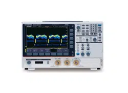
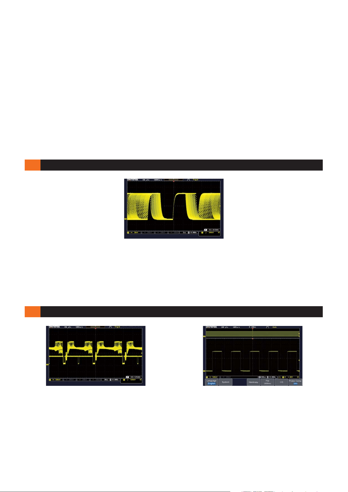
Nevertheless, the series arms itself with the waveform update rate
up to 50,000wfms/s and VPO waveform display technology. Users
can input a rapid frequency modulation carrier signal as shown on
the diagram. An unsmooth temporarily holding phenomenon will
occur while using conventional digital oscilloscopes to measure
this signal. As a result, the conventional digital oscilloscopes could
WAVEFORM UPDATE RATE UP TO 50,000wfms/s AND VPO DISPLAY TECHNOLOGY
With respect to the waveform display technology, the GDS-1000B
Series oscilloscope is capable of displaying 256 color gradients
which can delineate the profound gradational fluctuations; as if it
can recreate the analog oscilloscope display capability. When a
multi-layer video signal is input, the GDS-1000B Series, with 256
color gradient display, has the ability to precisely reveal the
B.
256 COLOR GRADIENT DISPLAY & 10M MEMORY DEPTH PER CHANNEL INDEPENDENTLY
colored burst signal and to show details of layers with the
brightness. Hence, the dull monochrome waveform is imbued
with vitality, which is precisely the unlimited measurement
fascination the GDS-1000B Series intents to bring to the general
purpose oscilloscope arena.
not clearly yield the modulation variation process of frequency
modulation signals. With the GDS-1000B Series oscilloscope,
the measurement result will produce not only a smooth waveform
modulation variation, but also detailed changes by distinct layers.
Engineers could easily grasp the root cause of electric circuits
while measuring the unexpected and fast changing signals. The
GDS-1000B Series is indeed an excellent debugging weapon for
the test and measurement industry.
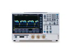
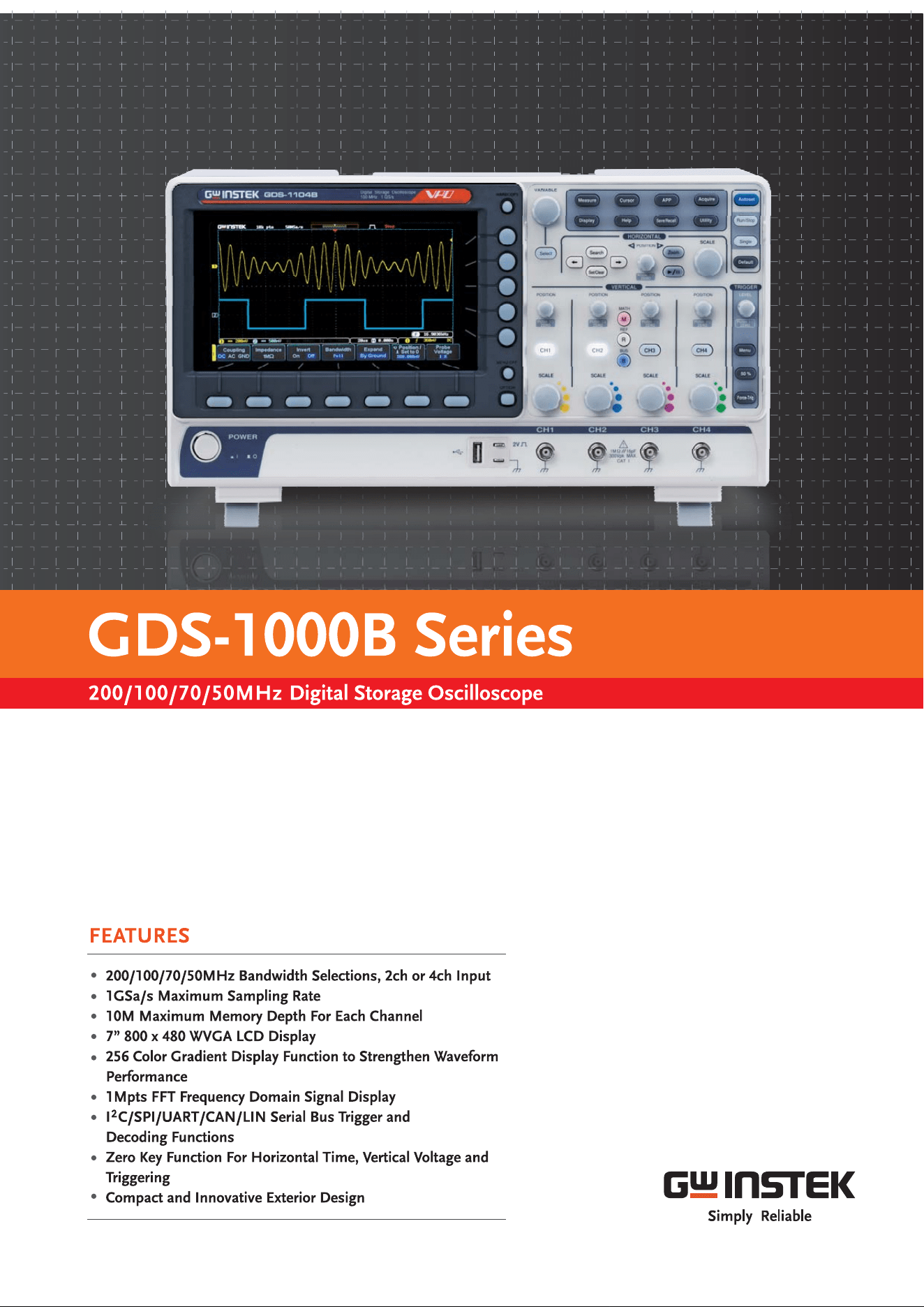
The GDS-1000B Series features four bandwidth selections - 200MHz, 100 MHz, 70 MHz, 50MHz and equips with analog
signal input terminals by four or two channels. The maximum sampling rate for each single channel is 1GSa/s, and the
memory depth is 10Mpts per channel independently. The GDS-1000B Series has a waveform update rate of 50,000wfms/s,
which helps users to precisely observe the detailed waveform variation. Additionally, 7” WVGA color LCD display and the
256 color gradient display function together allow waveforms to be observed with the senses of transparency and gradation.
With respect to the horizontal time scale adjustment knob and trigger level adjustment knob, GW Instek provides a very
thoughtful design -the zero key function, which allows engineers to work more effectively. For mathematical analysis mode,
1Mpts FFT signal display makes the dull frequency domain signal analysis more delicate.
Moreover, the innovative exterior design and compact design also bring much convenience to users.
Other diversified and charming multi-functional operation demonstrates the concept of complete technology integration.
The GDS-1000B Series oscilloscope has a powerful and incomparable
memory depth for the data retrieving. 10M memory depth per channel
independently surpasses the specification of the industry's 1000 Series
boundary. 10M memory depth allows users to easily seize the waveform
detail while conducting fundamental measurement applications. If a
long serial sequent sine waveformis input and the time scale is adjusted
to 1mv/div, other GDS-1000 Series oscilloscopes for lack of sufficient
memory depth will appear a distorted waveform while enlarging the
waveform for its details. The GDS-1000B Series while enlarging the
waveform to 20ns/div reveals a very clear sine waveform detail which is
precisely the true value of the GDS-1000B Series oscilloscope.
D. E.
ZOOM IN/PLAY AND PAUSE FUNCTION
F. G.
1M FFT MATHEMATICAL SAMPLING ANALYSIS MODE
C.
The GDS-1000B series provides engineers with partial waveform zoom
in function to observe waveform in great details. The display screen
can be split into two windows: the upper window shows waveform data
log in a long period of time and the marked vicinity of the waveform
needed to be zoomed in; the lower window shows the enlarged partial
waveform. The function not only allows engineers to make a
comparison but also grasp waveform details in the different timeframe.
Additionally, the GDS-1000B series also features the play/pause
function. For the long waveform observation, the play/pause function
facilitates engineers to rapidly skim through the whole section of DUT's
waveforms as well as to swiftly identify waveform's problems.
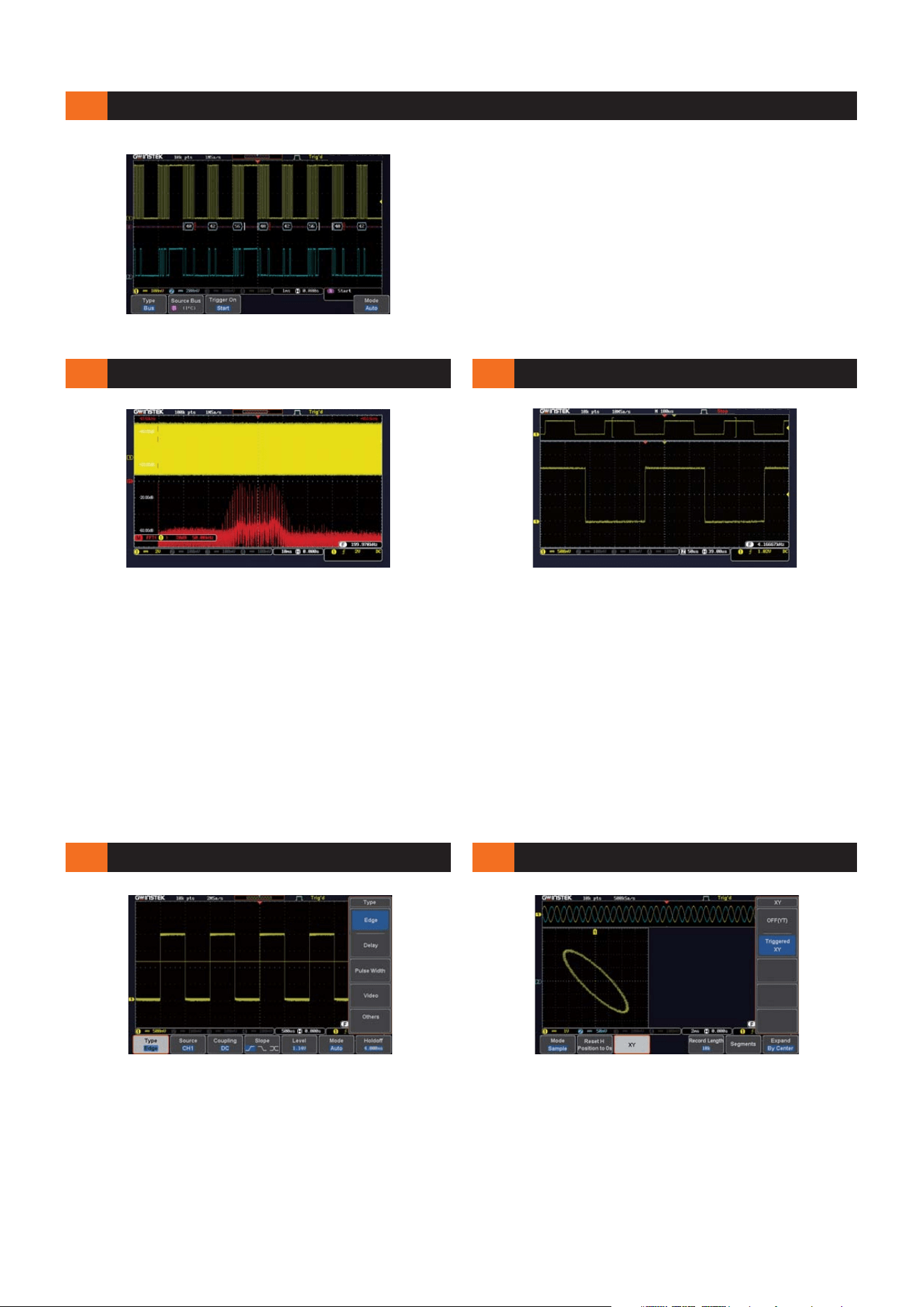
DIVERSIFIED TRIGGER FUNCTIONS
X-Y MODE DISPLAY
The GDS-1000B series oscilloscope provides the educational market
with some powerful measurement functions. Among them, the X-Y
mode display is an excellent example. Teachers and students can use
X-Y mode display to conduct Lissajou diagram teaching, which allows
users to easily understand the relation between waveforms and
frequency while measuring sine waveforms with different frequency by
dual channels. For engineers working for the industries, the X-Y mode
display can be used to conduct yield rate tests for basic components'
electric conduction and non conduction. Therefore, the X-Y mode
display plays an important role in basic oscilloscopes.
The GDS-1000B series oscilloscope is equipped with diversified
trigger functions, including Edge Trigger, Delay Trigger, Pulse Width
Trigger, and Video Trigger. Engineers, based upon different waveform
measurements, can select different trigger functions to lock
waveforms in order to identify the root cause of the complicated
circuit designs to save development time and to accomplish tasks.
The GDS-1000B Series oscilloscope, under the Fast Fourier Transform
mathematical analysis mode, is equipped with the 1M memory depth
retrieving mode. For the conventional digital oscilloscopes, the FFT mode
often has only 1000 point retrieving length; therefore, they can not show
the strength distribution of each spectrum quantity under the frequency
domain mode. The GDS-1000B Series oscilloscope leads the industry to
provide the display mode of 1M retrieving points, which can clearly show
the detail of each spectrum quantity. On top of that, the 50,000 wfms/s
waveform update rate augments the FFT analysis mode to be fast and
precise as if a real time spectrum analyzer is used. These features
substantially elevate oscilloscope's signal processing capability for the
frequency domain analysis. The diagram illustrates a 200 kHz carrier
waveform to be modulated as a standard FM signal with 40 kHz and
5 kHz frequency deviation. Since the GDS-1000B Series is equipped with
1M memory depth, a 5 kHz frequency deviation interval can be clearly
revealed that allows engineers to fully grasp the measurement details.
SUPPORT I C ,SPI ,UART,CAN, LIN BUS TRIGGER AND DECODING FUNCTIONS
2
The serial bus technology has been widely applied in the present
embedded application design. The IoT devices connecting sensors
and the peripheral components are using serial bus such as UART,
I C, and SPI. To rapidly and correctly trigger and analyze serial bus
2
data has posed a difficult challenge to engineers. The GDS-1000B
series provides serial bus analysis function with 10M long memory
depth. Users can trigger, decode, and analyze frequently used I C,
2
SPI and UART serial bus and CAN/LIN bus, which is often used by
automotive communications.
L.
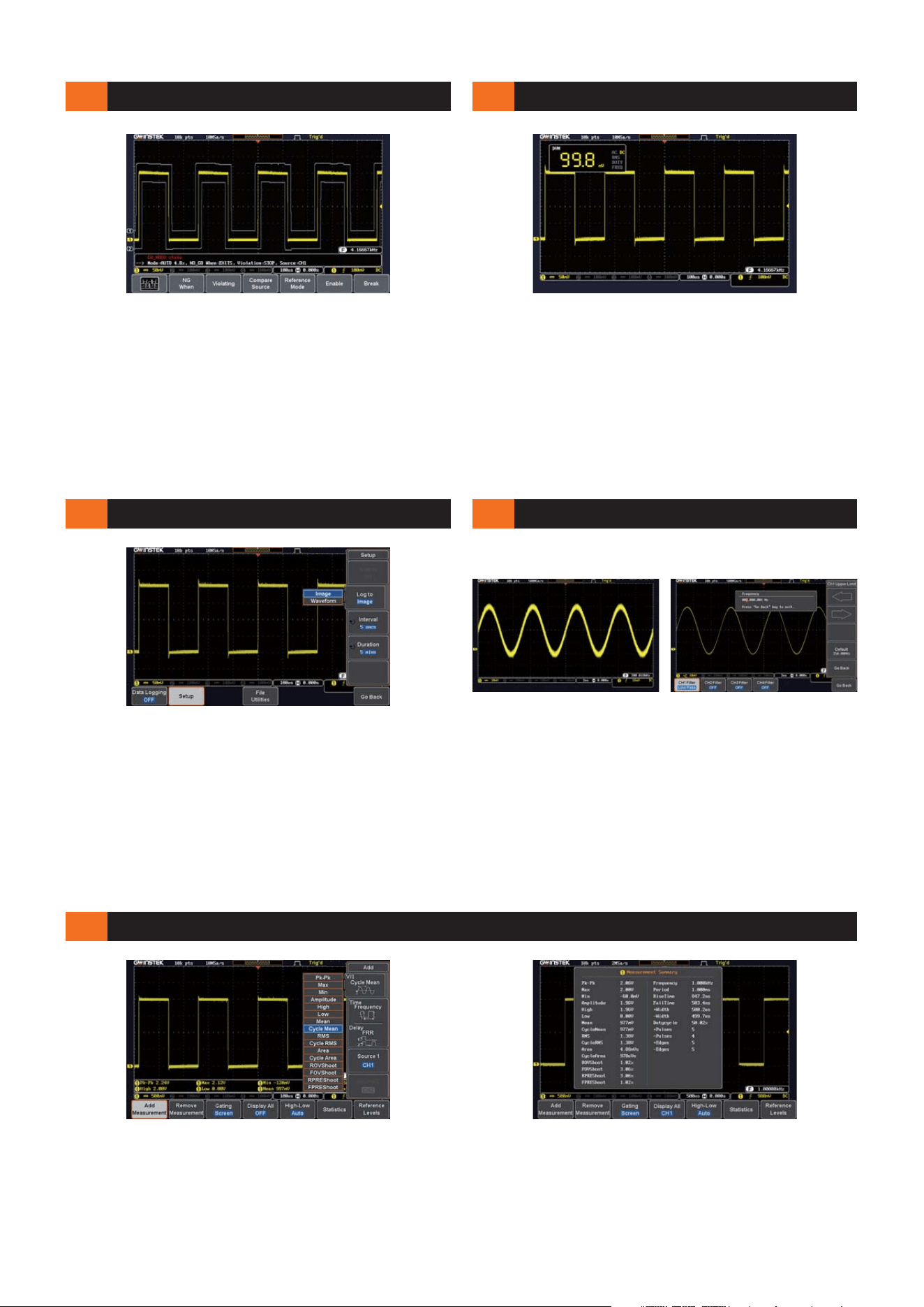
36 MEASUREMENT PARAMETER SELECTIONS
The GDS-1000B series oscilloscope is equipped with 36 different
automatic measurement parameter functions. Users, after
obtaining measured waveforms, can select different measurement
parameters from Measure key according to different measurement
requirements. The GDS-1000B Series shows simultaneously eight
sets of different measurement parameters on the bottom of the
display screen. Users can also select to show all parameters if
the preset eight sets are insufficient. Once the selection is made,
all 36 measurement parameters will be shown on the center of
the display screen. This is a very convenient measurement tool
for students writing dissertations or engineers writing reports.
J.
DATA LOG FUNCTION
K.
DIGITAL FILTER FUNCTION
H. I.
GO/NOGO FUNCTION
DIGITAL VOLTAGE METER FUNCTION
For electric circuit measurement and debugging, R&D engineers
require oscilloscopes as well as basic voltage meters. The GDS-1000B
series oscilloscope equips with a digital voltage meter with three-digit
voltage value and five-digit frequency value. Engineers, by pressing
the option key, can select the digital voltage meter function from the
menu to measure DC/AC voltage, duty cycle, and frequency.
Engineers can not only measure waveforms but also monitor the
electric parameters of each component on the circuit board. The
function is a very convenient tool.
The GDS-1000B Series oscilloscope has the data log function option,
which allows users to observe and record waveform changes in a long
period of time to ensure product's reliability and stability. The data log
function can set data storage time and interval based on the test
requirements. Record time can be set from 5 minutes to 100 hours
and the interval can be set as 5 seconds the shortest. Data log formats
include waveform and point data in CSV file. Data can be saved to
USB, GDS-1000B or remote computer via LAN. It is very user-friendly
and also an advanced measurement management tool.
For the industries, the yield rate determination is very important to
mass production. The GDS-1000B series oscilloscope provides the
Go/NoGo analysis function to accelerate the yield rate analysis.
From the right diagram, the Go/NoGo function provides a standard
waveform template for examining DUT's waveforms. The function
can freely adjust the size of template. A defect message will be shown
if the DUT's waveform is abnormal and touches the template. The
function is not only very useful measurement tool for production lines
but also a very convenient tool for engineers to observe waveforms in
a long period of time.
* Users need to download this application from GW Instek website
* Users need to download this application from GW Instek website
* Users need to download this application from GW Instek website
In electric circuit tests, engineers are often troubled by noise
interference while measuring signals. The GDS-1000B series
oscilloscope provides the digital filter function option, which can
be set as high pass or low pass filter. The filter frequency can be
adjusted according to the requirements. The filter parameters of
each channel can also be set. The tracking on function can be
used to set same filter frequency for all channels.
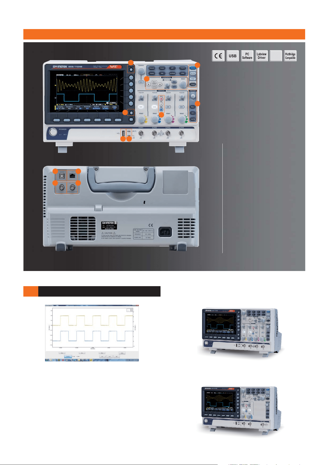
PANEL INTRODUCTION
Ethernet
M.
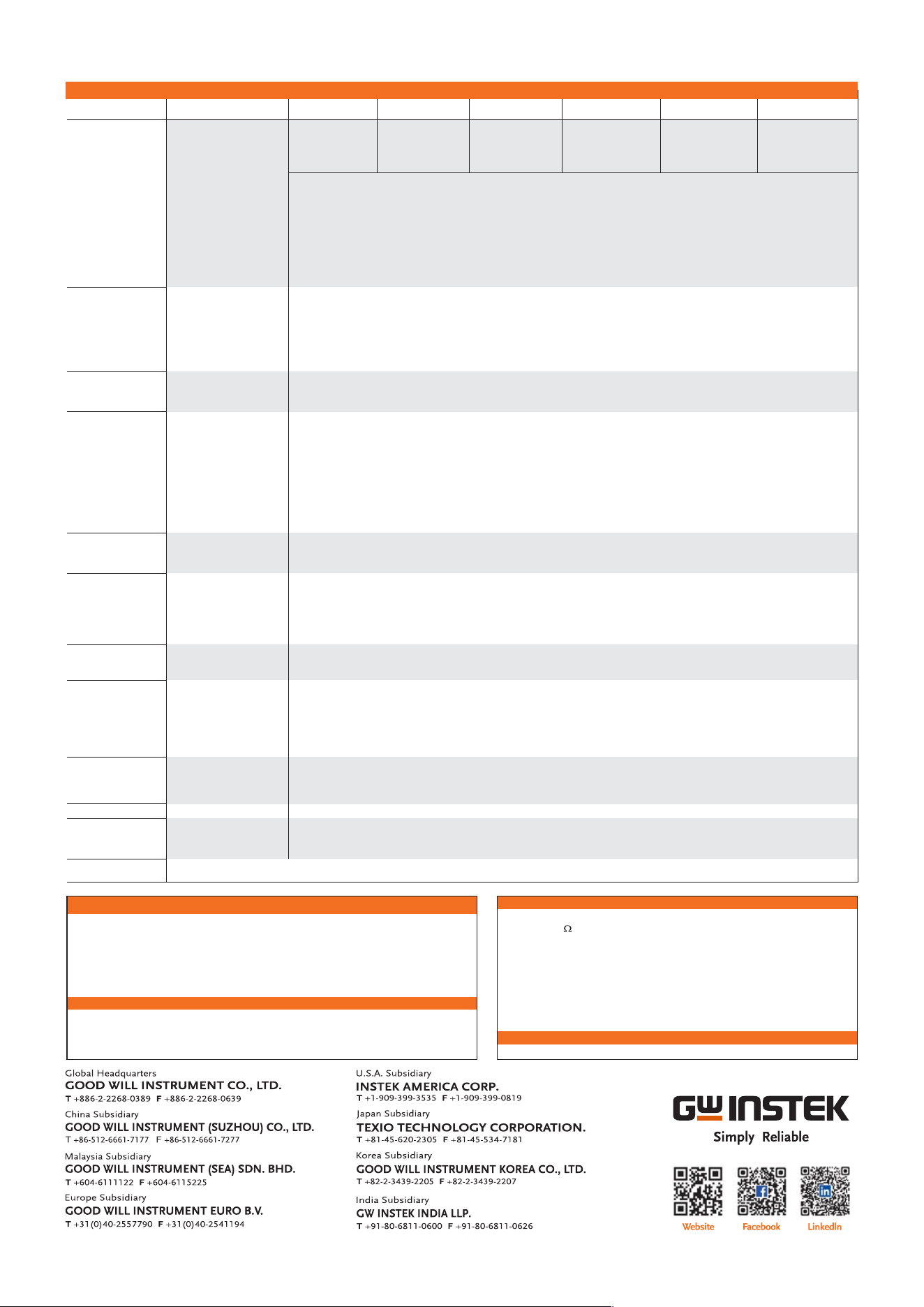
OPENWAVE CONNECTION SOFTWARE
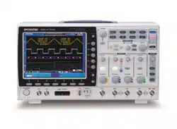
4 Channel Model
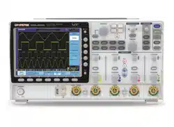
2 Channel Model
The GDS-1000B Series oscilloscope, via the OpenWave connection
software developed by GW Instek, can connect with the PC. Users,
after installing USB driver under Windows interface, can connect
GDS-1000B with the PC through USB cable and OpenWave
software. Waveform interpretation and retrieval can be done from
the PC end. Data retrieval and storage can better facilitate users
in processing analysis. OpenWave connection software is indeed
a very powerful tool for engineers to compile reports or to
integrate systems.
GDS-1102B
GDS-1202B
GDS-1072B
100MHz
200MHz
70MHz
GDS-1104B
GDS-1074B
100MHz
70MHz
GDS-1054B 50MHz
1. Hardcopy key
2. Autoset, Run/Stop, Single &
Default keys
3. Zooming Controls
4. Trigger controls
5. Math, Reference & Bus keys
6. Probe calibration output
7. USB Host port
8. Menu off key
9. USB device port
10. LAN port
11. Go-NoGo output
12. Calibration output
1
3
4
6
2
7
5
8
9
10
11
12
DS-1000BGD4BH
Specifications subject to change without notice.
GDS-1072BGDS-1054B GDS-1074B GDS-1102B GDS-1104B GDS-1202B
Channels
2 + Ext4 4 2 + Ext 4
Bandwidth
DC~70MHz(-3dB)DC~50MHz(-3dB) DC~70MHz(-3dB) DC~100MHz(-3dB) DC~100MHz(-3dB) DC~200MHz(-3dB)
Calculated Rise Time
Bandwidth Limit
5ns7ns
20MHz20MHz 20MHz 20MHz 20MHz 20MHz
5ns
3.5ns 3.5ns 1.75ns
380(W) 208 (H) 127.3(D)mm, Approx. 2.8kg××
Operation Environment
Multi-Language Menu
Online Help
Temperature : 0°C ~ 50°C. Relative Humidity 80% at 40°C or below; 45% at 41°C ~ 50°C≤≤
Available
Available
AC 100V ~ 240V , 50Hz ~ 60Hz , Auto selection , Power consumption: 30 Watts
VERTICAL
MISCELLANEOUS
DIMENSIONS &
WEIGHT
POWER SOURCE
SPECIFICATIONS
The specifications apply when the GDS-1000B is powered on for at least 30 minutes under +20°C~+30°C .
Vertical Sensitivity Resolution
Input Coupling
Input Impedance
DC Gain Accuracy*
Polarity
Maximum Input Voltage
Offset Position Range
Waveform Signal Process
8 bit : 1mV~10V/div
AC, DC, GND
±3%
Normal & Invert
300Vrms, CAT I (300Vrms CAT II with GTP-070B- 4/100B-4 10:1 probe)
, 200B-4
1mV/div : ±1.25V ; 2mV/div ~ 100mV/div : ±2.5V ; 200mV/div ~ 10V/div : ±125V
TRIGGER Source
Trigger Mode
Trigger Type
CH1, CH2, CH3*, CH4*, Line, EXT** ; *four channel models only. ; **two channel models only
Auto (supports Roll Mode for 100 ms/div and slower), Normal, Single Sequence
Edge, Pulse Width, Video, Pulse Runt, Rise & Fall, Timeout, Alternate, Event-Delay(1~65535 events),
Time-Delay(Duration, 4nS~10S)
Sensitivity
1div
Holdoff range
4ns to 10s
Coupling
AC, DC, LF rej., Hf rej., Noise rej.
EXTERNAL TRIGGER
Range
Sensitivity
Input Impedance
±2.5V
DC ~ 100MHz Approx. 100mV ; 100MHz ~ 200MHz Approx. 150mV
1M ±3%~16pF
Ω
HORIZONTAL Time base Range
ROLL
Pre-trigger
Post-trigger
Timebase Accuracy
Real Time Sample Rate
Record Length
Acquisition Mode
Peak Detection
Average
5ns/div ~ 100s/div (1-2-5 increments)
100ms/div ~ 100s/div
10 div maximum
2,000,000 div maximum
±50 ppm over any 1 ms time interval
≥
1GSa/s max.
Max. 10Mpts
Normal, Average, Peak Detect, Single
2nS (typical)
selectable from 2 to 256
X-Y MODE
X-Axis Input
Y-Axis Input
Phase Shift
Channel 1; Channel 3*(*four channel models only)
Channel 2; Channel 4*(*four channel models only)
±3° at 100kHz
CURSORS AND
MEASUREMENT
Cursors
Automatic Measurement
Cursors Measurement
Auto Counter
Amplitude, Time, Gating available; Unit : Seconds(s), Hz(1/s), Phase(degree), Ration(%)
36 sets: Pk-Pk, Max, Min, Amplitude, High, Low, Mean, Cycle Mean, RMS, Cycle RMS, Area, Cycle Area, ROVShoot,
FOVShoot, RPREShoot, FPREShoot, Frequency, Period, RiseTime, FallTime, +Width, -Width, Duty Cycle, +Pulses,
-Pulses, +Edges, -Edges, FRR, FRF, FFR, FFF, LRR, LRF, LFR, LFF, Phase
Voltage difference between cursors ( V) Time ; difference between cursors ( T)
ΔΔ
6 digits, range from 2Hz minimum to the rated bandwidth
CONTROL PANEL
FUNCTION
Autoset
Single-button, automatic setup of all channels for vertical, horizontal and trigger systems, with undo Autoset
Save Setup
20set
Save Waveform
24set
DISPLAY
TFT LCD Type
Display Resolution
Interpolation
Waveform Display
Waveform Update Rate
Display Graticule
Display Mode
7" TFT WVGA color display
800 horizontal × 480 vertical pixels (WVGA)
Sin(x)/x
Dots, vectors, variable persistence (16ms~4s), infinite persistence
50,000 waveforms per second, maximum
8 x 10 divisions
YT, XY
INTERFACE
USB Port
Ethernet Port(LAN)
Go-NoGo BNC
Kensington Style Lock
USB 2.0 High-speed host port x1, USB High-speed 2.0 device port x1
RJ-45 connector, 10/100Mbps with HP Auto-MDIX (Only for 4 channel models.)
5V Max/10mA TTL open collector output
Rear-panel security slot connects to standard kensington-style lock
+,-, ×, ÷, FFT, FFTrms, User Defined Expression ; FFT: 1Mpts; FFT: Spectral magnitude. Set FFT Vertical Scale to
Linear RMS or dBV RMS ; FFT Window Display : Rectangular, Hamming, Handing, or Blackman-Harris
ORDERING INFORMATION
Driver
OpenWave Software
USB Driver ; LabView Driver
OPTIONAL ASSESSORIES
FREE DOWNLOAD
GDS-1104B
GDS-1202B
GDS-1102B
GDS-1074B
GDS-1072B
GDS-1054B
100MHz, 4 channels, Digital Storage Oscilloscope
200MHz, 2 channels, Digital Storage Oscilloscope
100MHz, 2 channels, Digital Storage Oscilloscope
70MHz, 4 channels, Digital Storage Oscilloscope
70MHz, 2 channels, Digital Storage Oscilloscope
50MHz, 4 channels, Digital Storage Oscilloscope
ACCESSORIES
Software
2 + Ext
1M // 16pF approx. ; GDS-1202B : 1M // 14pF approx.ΩΩ
User manual CD x 1, Power cord x 1
GTP-070B-4 : 70MHz(10:1/1:1) Switchable passive probe for (one per channel)GDS-1074B,GDS-1072B,GDS-1054B
GTP-100B-4 : 100MHz(10:1/1:1) Switchable passive probe for (one per channel)GDS-1104B, GDS-1102B
GTP-200B-4 : 200MHz(10:1/1:1) Switchable passive probe for (one per channel)GDS-1202B
GSC-008
Soft Carrying Case
GRA-426
GAK-003
Rack Adapter Panel
50 Impedance Adapter
GTL-246
USB Cable, USB 2.0,
A-B Type, 1200mm
GCP-530
GCP-1030
GTP-033A
Oscilloscope Probe, 35MHz
1:1 Passive Probe, BNC(P/M)
GDP-025
GDP-050
GDP-100
100MHz High voltage differential probe
25MHz High voltage differential probe
50MHz High voltage differential probe
GCP-206P
GCP-425P
Power supply for current probe
(2 input channel)
Power supply for current probe
(4 input channel)
100MHz/30A Current probe
50MHz/30A Current probe
GCP-300
GCP-500
GCP-1000
300kHz/200A Current probe
500kHz/150A Current probe
1MHz/7A Current probe