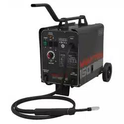
150A PROFESSIONAL GAS/NO-GAS MIG WELDER
MODEL NO: MIGHTYMIG150.V3
Thank you for purchasing a Sealey product. Manufactured to a high standard, this product will, if used according to these instructions,
and properly maintained, give you years of trouble free performance.
IMPORTANT: PLEASE READ THESE INSTRUCTIONS CAREFULLY. NOTE THE SAFE OPERATIONAL REQUIREMENTS, WARNINGS & CAUTIONS. USE
THE PRODUCT CORRECTLY AND WITH CARE FOR THE PURPOSE FOR WHICH IT IS INTENDED. FAILURE TO DO SO MAY CAUSE DAMAGE AND/OR
PERSONAL INJURY AND WILL INVALIDATE THE WARRANTY.
1. SAFETY
1.1. ELECTRICAL SAFETY
WARNING! It is the user’s responsibility to check the following:
9 Check all electrical equipment and appliances to ensure that they are safe before using. Inspect power supply leads, plugs and all
electrical connections for wear and damage. Sealey recommend that an RCD (Residual Current Device) is used with all electrical
products.
Electrical safety information. It is important that the following information is read and understood:
9 Ensure that the insulation on all cables and on the appliance is safe before connecting it to the power supply.
9 Regularly inspect power supply cables and plugs for wear or damage and check all connections to ensure that they are secure.
Important: Ensure that the voltage rating on the appliance suits the pow er supply to be used and that the plug is fitted with the
correct fuse.
8 DO NOT pull or carry the appliance by the power cable.
8 DO NOT pull the plug from the socket by the cable.
8 DO NOT use worn or damaged cables, plugs or connectors. Ensure that any faulty item is repaired or is replaced immediately by a
qualified electrician.
If the cable or plug is damaged during use, switch off the elect ricity supply and remove from use.
Ensure that repairs are carried out by a qualified electrician.
8 DO NOT use with medical implants. Ensure the unit is correctly earthed via a three-pin plug.
1.1.1. Cable extension reels. When a cable extension reel is used it should be fully unwound before connection. A cable reel with an RCD
fitted is recommended since any product which is plugged into the cable reel will be protected. The section of the cable on the cable
reel is important and should be at least 1.5mm², but to be absolutely sure that the capacity of the cable is suitable for this product
and for others that may be used in the other output sockets, we recommend the use of 2.5mm² section cable.
WARNING! Be very cautious if using a generator to power the welder. The generator must be self-regulating and stable with regard
to voltage, wave form and frequency. The output must be greater than the power consumption of the welder. If any of these requirements
is not met the electronics within the welder may be affected.
NOTE: The use of an unregulated generator may be dangerous and will invalidate the warranty on the welder.
WARNING! The welder may produce voltage surges in the mains supply which can damage other sensitive equipment (e.g. computers).
To prevent this happening, it is recommended that the welder is connected to a power supply that does not feed any sensitive equipment.
IMPORTANT! If using welder to full capacity, we recommend a 16amp supply. We recommend you discuss the installation of a 16amp
industrial round pin plug and socket with your electrician.
1.2. GENERAL SAFETY
▲ DANGER! Unplug the welder from the mains power supply before performing maintenance or service.
8 Welding power sources are not suitable for use in rain or snow.
8 The output is rated at an ambient temperature of 20°C and the welding time may be reduced at higher temperatures
8 Risk of electric shock: Electric shock from welding electrode can kill. DO NOT weld in the rain or snow. Wear dry insulating gloves. DO
NOT touch electrode with bare hands. DO NOT wear wet or damaged gloves. Protect yourself from electric shock by insulating yourself
from workpiece. DO NOT open the equipment enclosure.
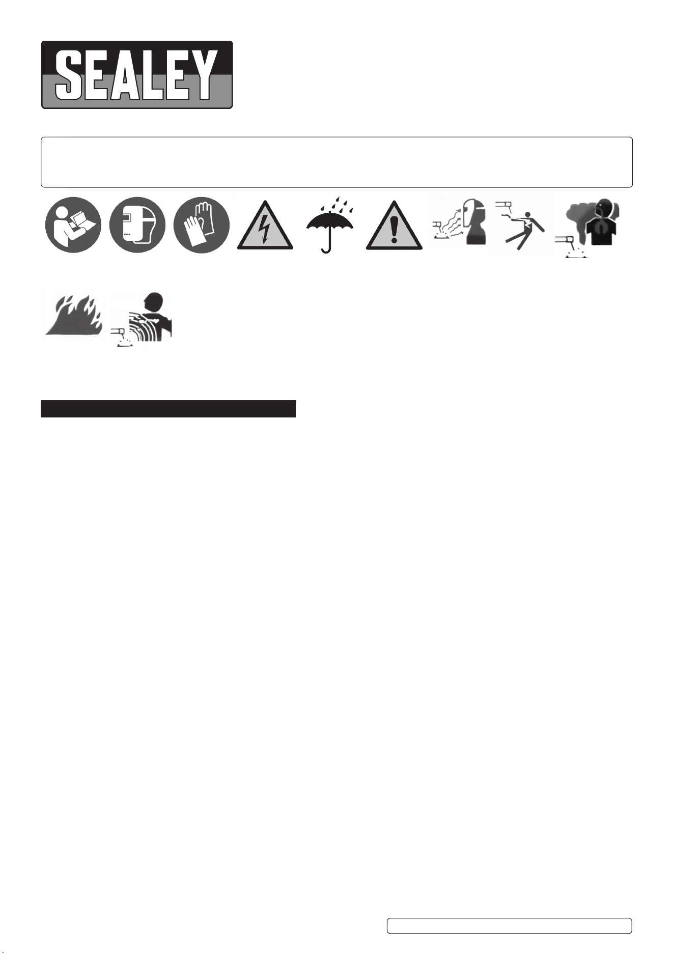
Refer to
instruction
manual
Wear a
welding
mask
Wear protective
gloves
Warning!
Electricity
shock hazard
Warning!
Keep away
from rain
Caution
required
Arc rays can
burn eyes and
injure skin
Breathing weld-
ing fumes can
be hazardous
to your health
Electric shock
from welding
electrodes can
kill
Welding sparks
can cause
explosions or fire
Original Language Version
© Jack Sealey Limited
MIGHTYMIG150.V3 Issue:3 (8) 02/11/23
Electromagnetic
elds can cause
pacemaker
malfunction

WARNING! Risk induced by welding fumes: Breathing welding fumes can be hazardous to your health. Keep your head out of the fumes.
Use equipment in an open area. Use ventilating fan to remove fumes.
WARNING! Risk induced by welding sparks: Welding sparks can cause explosion or fire. Keep flammables away from welding. DO NOT
weld near flammables. Welding sparks can cause fires. Have a fire extinguisher nearby and have a watchperson ready to use it. DO NOT
weld on drums or any closed containers.
WARNING! Risk induced by the arc: Arc rays can burn eyes and injure skin. Wear hat and safety glasses. Use ear protection and button
shirt collar. Use welding helmet with correct shade of filter. Wear complete body protection.
WARNING! Risk induced by electromagnetic fields: Welding current produces electromagnetic field. DO NOT use with medical implants.
Never coil welding cables around your body. Route the welding cables together.
▲ DANGER! Never coil welding cables around your body.
9 Keep the welder and cables in good working order and condition. Take immediate action to repair or replace damaged parts. And route the
welding cables together.
9 Use genuine parts and accessories only. Unapproved parts may be dangerous and will invalidate the warranty.
9 Use an air hose to regularly blow out any dirt from the liner and keep the welder clean for best and safest performance.
9 Check and spray the gas cup and contact tip regularly with anti-spatter spray, available from your Sealey stockist.
9 Locate welder in a suitable work area. Ensure that the area has adequate ventilation as welding fumes are harmful.
9 Keep work area clean, tidy and free from unrelated materials. Also ensure the working area has adequate lighting and that a fire
extinguisher is at hand.
WARNING! Use welding head shield to protect eyes and avoid exposing skin to ultraviolet rays given off by electric arc. Wear
safety welding gauntlets and complete body and ear protection.
WARNING! Risk induced by electromagnetic fields: Welding current produces electromagnetic field.
WARNING! Risk induced by welding sparks: Welding sparks can cause explosion or fire. Keep flammables away from welding.
Do not weld near flammables. Welding sparks can cause fires. Have a fire extinguisher nearby and have a watch person ready to
use it. Do not weld on drums or any closed containers.
WARNING! ‘Risk induced Welding fumes: Breathing welding fumes can be hazardous to your health. Keep your head out of the
fumes. Use equipment in an open area. Use ventilating fan to remove fumes.
WARNING! Risk of electric shock: Electric shock from welding electrodes can kill.
9 Remove ill fitting clothing, remove ties, watches, rings and other loose jewellery and contain long hair.
9 Ensure the workpiece is correctly secured before welding.
9 Avoid unintentional contact with the workpiece. Accidental or uncontrolled use of the torch may be dangerous and will wear the nozzle.
9 Keep unauthorised persons away from the work area. Any persons working within the area must wear a protective head shield and gloves.
9 Operators must receive adequate training before using the welder.
9 Stand correctly keeping a good footing and balance, ensure the floor is not slippery and wear non-slip shoes.
8 DO NOT operate the welder if it or the cables are damaged and DO NOT attempt to fit any unapproved torches or other
components to the welder.
8 DO NOT get welder wet or use in damp or wet locations or areas where there is condensation. DO NOT use welder on uneven ground.
▲ DANGER! DO NOT weld near flammable solids, liquids or gases and DO NOT weld containers or pipes which have held flammable
materials. Avoid welding materials which have been cleaned with chlorinated solvents. DO NOT use power source for pipe thawing.
8 DO NOT stand welder on a metal workbench, car bodywork or similar.
8 DO NOT touch any live metal parts of the torch or electrode while the machine is switched on.
8 DO NOT pull the welder by the cable, or the torch. Protect cables from sharp or abrasive items. DO NOT bend, strain or stand on cables
or leads.
8 DO NOT wear wet or damaged gloves.
8 DO NOT open the equipment enclosure while welder is switched on.
9 Protect from heat. Long lengths of slack must be gathered and neatly coiled. DO NOT place cables where they endanger others.
8 DO NOT touch the torch or workpiece immediately after welding as they will be very hot. Allow to cool.
8 DO NOT operate welder while under the influence of drugs, alcohol or intoxicating medication, or if tired. When not in use store the welder
in a safe, dry, childproof area.
1.3. GAS SAFETY
9 Store gas cylinders in a vertical position only and ensure the storage area is correctly secured.
8 DO NOT store gas cylinders in areas where the temperature may exceed 50°C. DO NOT use direct heat on a cylinder. Always keep gas
cylinders cool.
8 DO NOT attempt to repair or modify any part of a gas cylinder or valve and DO NOT puncture or damage a cylinder.
8 DO NOT obscure or remove any official labels on a cylinder. Always check the gas identity before use. Avoid getting gas cylinders oily or
greasy.
8 DO NOT lift a cylinder by the cap, guard or valve. Always keep caps and guards in place and close valve when not in use.
2. INTRODUCTION
Heavy-duty high output transformer and forced-air cooling to maximize duty cycle performance. Supplied with comfort grip non-live torch,
1.8m earth cable, 1m gas hose, 0.45kg flux cored wire and 1mm contact tip. Set up in the no-gas welding mode, but can also easily be
switched to gas by simple change of polarity and the purchase of a Gas Conversion Kit - Model No. 120.802032.
IMPORTANT: These instructions contain the information you require to prepare your machine for welding, together with a maintenance
and a troubleshooting section. The instructions are not intended to teach you how to weld. If you have no experience, we recommend that
you seek training from an expert source. MIG welding is relatively easy, but does require a steady hand and supervised practice on scrap
metal, as it is only with continued practice that you will achieve the desired results.
S
Original Language Version
© Jack Sealey Limited
MIGHTYMIG150.V3 Issue:3 (8) 02/11/23
3. SPECIFICATION
4. ASSEMBLY
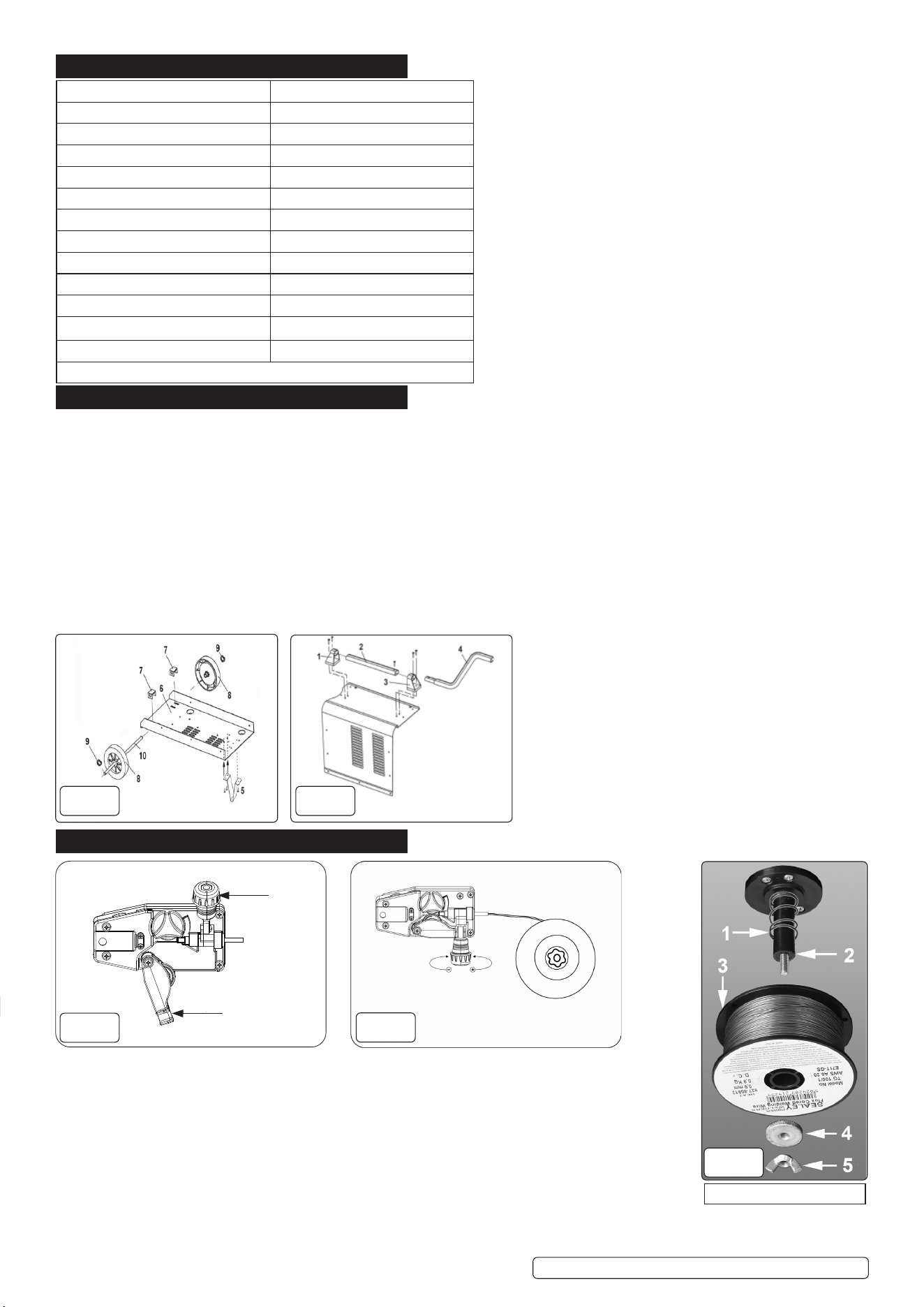
4.1. ASSEMBLY OF WHEELS (See fig.1)
4.1.1. Drop the axle brackets (7) through the slots in the rear of the bottom tray (6).
4.1.2. Attach a circlip (9) to one end of the axle (10) and slide a wheel (8) onto the axle and right up to the circlip.
4.1.3. Pass the axle (10) under the tray (6) and through the two protruding brackets (7) until the rst assembled wheel is up against the side of
the tray.
4.1.4. Slide the other wheel (8) onto the other end of the axle (10) and secure it by attaching a circlip (9) to the end of the axle.
4.2. ASSEMBLY OF FRONT FOOT (See fig.1).
4.2.1. Place the foot (5) onto the underside of the tray (6) ensuring that the three holes on the foot align with the holes in the tray. Fix the foot
in place with three self tapping screws.
4.3. ASSEMBLY OF HANDLE (See fig.2).
4.3.1. Attach the rear handle bracket (1) to the top of the casing using two self tapping screws. Slide the straight handle (2) into the bracket
(1) and slide the other bracket (3) onto the front end of the handle. Secure bracket (3) with two self tapping screws. Insert the handle
extension (4) into the front end of the handle and secure it with a self tapping screw.
5. PREPARATION
5.1. FITTING A REEL OF WIRE (g.3, g.4, g.5)
5.1.1. Lift the black catch on the side of the welder and open the side compartment to gain access to the wire
Feed unit mechanism and the wire spool holder. See g.3. The welder is supplied with a mini spool
containing 0.45kg of ux cored wire.
5.1.2. Referring to g.5, rotate the knob (5) anti-clockwise and remove it from the threaded spindle together
with the pressure disc (4). Leave the spring (1) on the spindle (2).
5.1.3. Place the wire reel (3) over the spindle and down onto the spring ensuring that the wire will withdraw
from the top of the spool in a forwards direction towards the wire feed unit.
5.1.4. Push lightly down on the top of the reel of wire and screw the pressure disc (4) onto the end of the
spindle and down onto the top of the wire reel. The reel take o pressure should be set to provide a mild
braking eect to prevent overrun where loose coils of wire form on the reel. DO NOT overtighten the
pressure disc as too much braking will conict with the wire tension set on the wire drive unit.
D
C
fig.
1
fig.
2
fig.
3
fig.
4
Model No: MIGHTYMIG150.V3
Welding Current: 30-150A
Wire Capacity: 0.9kg Gasless /0.7kg mild steel
Duty Cycle: 100% @ 30A, 15% @ 105A
Cooling System: Forced Air
Gas Type: CO2 Argon, CO2 /
Argon Mix
Torch: 2.1m Non-Live
Supply: 230V Bare wire
Cable length: 2m
Absorbed Power: 4.5kW
Case Size: Compact
Flux Cored Wire (0.9kg x Ø0.9mm): TG100/1
Replacement Tips 1mm (Pack of 5): TG100/2
Note: For use with 0.9kg Gasless and 0.7kg mild steel Wire Reels only.
fig.
5
Graphic for reference only
Original Language Version
© Jack Sealey Limited
MIGHTYMIG150.V3 Issue:3 (8) 02/11/23
Lock the position of the pressure disc by screwing the buttery nut (5) down on top of it.
5.1.5. Referring to g.3 turn the knob on the wire lock screw (C) anti-clockwise and lift it up and away from the
pressure roller moulding. Swing the pressure roller moulding (D) away from the drive roller.
5.1.6. Release the wire from the spool (do not allow wire to uncoil) and straighten 40-50mm of wire and gently
push through the exible plastic guide and through the 0.9mm feed roller groove and into the torch
liner. Refer to maintenance section 10.3 on how to reverse or change the roller for driving other wire
diameters.
5.1.7. Referring to g.4, move the pressure roller moulding back round onto the grooved drive wheel and swing
the wire lock screw back down to lock it in place. See section 5.2 regarding wire tension.
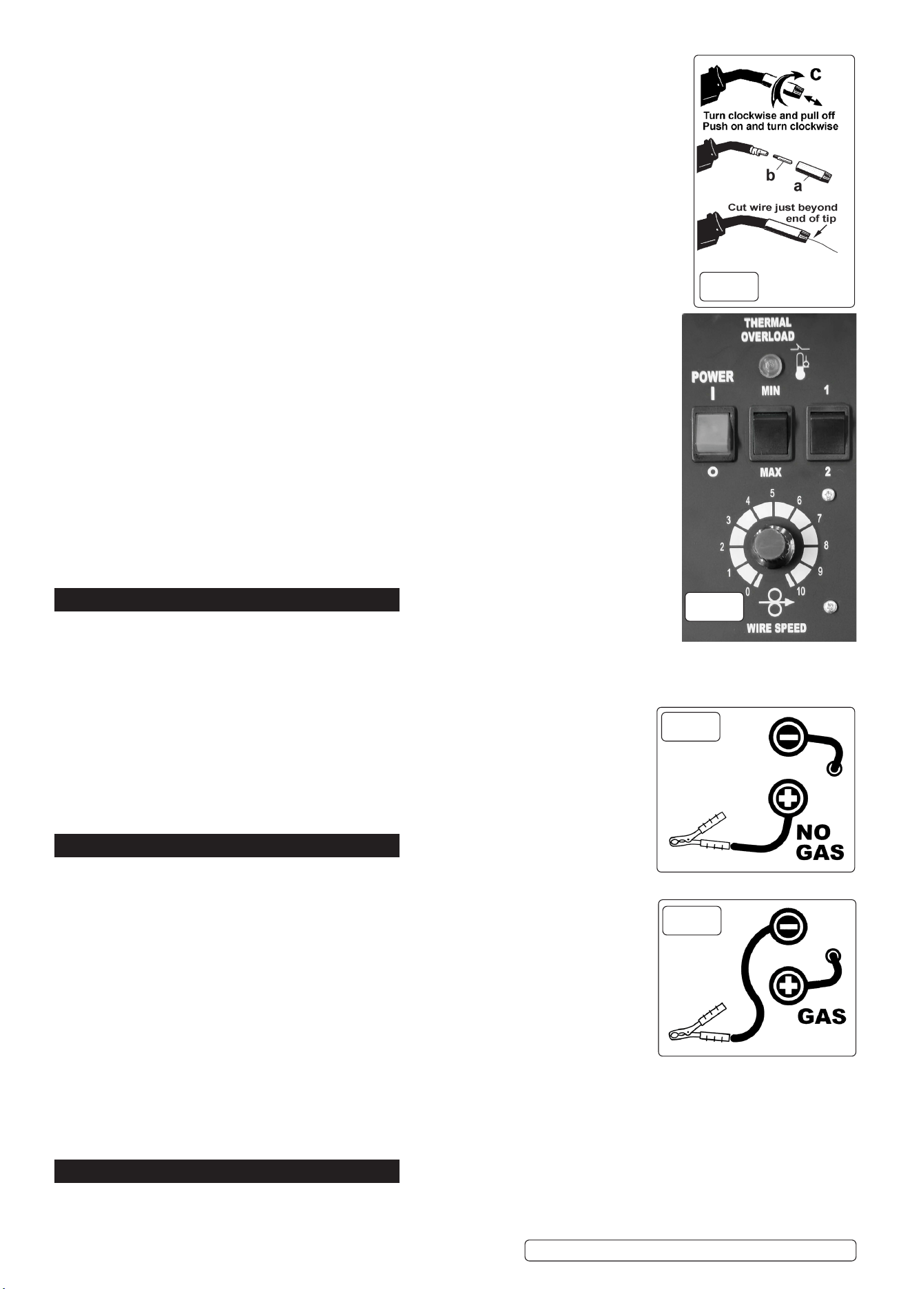
5.1.8. Feeding the wire through to the torch. (See g.6) Remove gas cup (a) and contact tip (b) from end of
torch as follows:
A) Take torch in left hand with the torch tip facing to the right.
B) Grasp gas cup rmly in your right hand.
C) Turn gas cup clockwise only and pull cup out to the right.
WARNING! DO NOT turn gas cup anti-clockwise, as this will damage internal spring. d) Unscrew
The copper contact tip (right hand thread) to remove.
5.1.9. Check welder is switched “OFF” and that the earth clamp is away from the torch tip. Connect the
welder to the mains power supply and set the current switch to MAX.
5.1.10. Set the wire speed knob to position 5 or 6. See g.7. Switch welder on. Keeping the torch cable as
straight as possible and press the torch switch. The wire will feed through the torch.
5.1.11. When wire has fed through, switch welder o, unplug from mains.
A) Take torch in left hand, slide the contact tip over the wire and screw it back into place.
B) Grasp gas cup in right hand, push onto torch head and turn clockwise only.
WARNING! DO NOT turn gas cup anti-clockwise, as this will damage internal spring. c) Cut wire so
that it is just protruding from the cup.
5.2. SETTING WIRE TENSION
IMPORTANT: You must set the correct tension, too little or too much tension will cause problematic
wire feed and result in a poor weld.Turn the wire lock screw clockwise to increase the tension and
anticlockwise to decrease the tension as shown in g.4.
5.2.1. Correct tension between the rollers is checked by slowing down the wire between gloved ngers. If the
pressure roller skids the tension is correct. Try to use the lowest tension possible as tension will deform
the wire. When you have completed welding allow the welder to cool before storing in a safe, dry
place. NOTE: Damaged torches and cables are not covered under warranty.
6. CONTROL PANEL
6.1. THERMAL OVERLOAD LIGHT (see g.7)
6.1.1. If the duty cycle is exceeded as a result of welding too long with a high current the yellow overload
light will illuminate and the welder will turn o. When the welder has cooled down (approx. 5 to 10
minutes) the power will be restored and welding can recommence.
6.2. POWER ON/OFF SWITCH (see g.7)
6.2.1. When the power is ON the green switch will be illuminated. When the welder is no longer
required it should be switched to the OFF position and the power plug should be disconnected
from the mains supply.
6.3. CURRENT SWITCHES MIN, MAX & 1, 2. (see g.7)
6.3.1. Used together these two switches provide 4 increasing power levels as follows: MIN/1, MIN/2,
MAX/1, MAX/2.
6.4. WIRE SPEED CONTROL KNOB. (see g.7)
6.4.1. As a general rule, a higher current requires a higher wire speed.
7. GASLESS OPERATION
WARNING! ENSURE THAT YOU READ, UNDERSTAND AND APPLY SAFETY INSTRUCTIONS
BEFORE OPERATING THE WELDER. IF WELDING A VEHICLE, DISCONNECT THE BATTERY
OR FIT AN ELECTRONIC CIRCUIT PROTECTOR.
7.1. POLARITY CHECK
7.1.1. Ensure that the welder is disconnected from the main power supply, open the side panel and check
that the polarity is correctly set up for gasless operation. The earth clamp wire must be connected
to the POSITIVE (+) terminal and the power (torch) lead must be connected to the NEGATIVE (-)
terminal as shown in fig.8.
7.2. To ensure a complete circuit, the earth clamp must be securely attached to the workpiece.
a) The weld area must also be free of paint, rust, grease, etc.
b) Obtain the best connection by grinding the point of contact on the workpiece before connecting
the clamp.
7.3. If welding a vehicle, disconnect the battery or fit a “Electronic Circuit Protector” (available from your
Sealey stockist).
7.4. Set up the current switches to give the required power setting and adjust the wire speed accordingly.
7.5. During the welding process, wire drawn from the spool is automatically fed through an insulated liner in the torch cable to the torch tip. The
torch switch activates the wire feed roller (to stop wire feed release the switch). As wire comes into contact with the workpiece an arc is
struck. The arc melts the wire which is deposited into the weld.
8. CONVERSION TO MIG WELDING
For welding stainless steel or aluminium, this welder can be converted to a conventional mig welder. To convert to gas, order a reel
of regular wire, a bottle of suitable gas, tips and nozzles and a conversion kit.
fig.
6
fig.
7
fig.
9
fig.
6
fig.
8
fig.
9
Original Language Version
© Jack Sealey Limited
MIGHTYMIG150.V3 Issue:3 (8) 02/11/23
Kit 120.802032 contains a regulator plus connection hoses, hose adaptor and jubilee clips (see fig.10).
8.1. CHECK POLARITY
8.1.1. Ensure that the welder is disconnected from the mains power supply and open the side panel and check that the polarity is correctly
set up for gas operation. The earth clamp wire must be connected to the NEGATIVE (-) terminal and the power (torch) lead must be
connected to the POSITIVE (+) terminal as shown in fig.9.
8.2. CHECK WIRE FEED ROLLER
8.2.1. If necessary, change and/or turn the wire feed roller (See maintenance section 10) so that the appropriately sized groove is in line with the
drive path i.e. in the groove nearest to you.
8.3. FIT REQUIRED WIRE
8.3.1. Fit a reel of steel or aluminium wire (either 0.6 or 0.8mm).
8.4. SET THE WIRE TENSION AS DESCRIBED IN SECTION 5.2
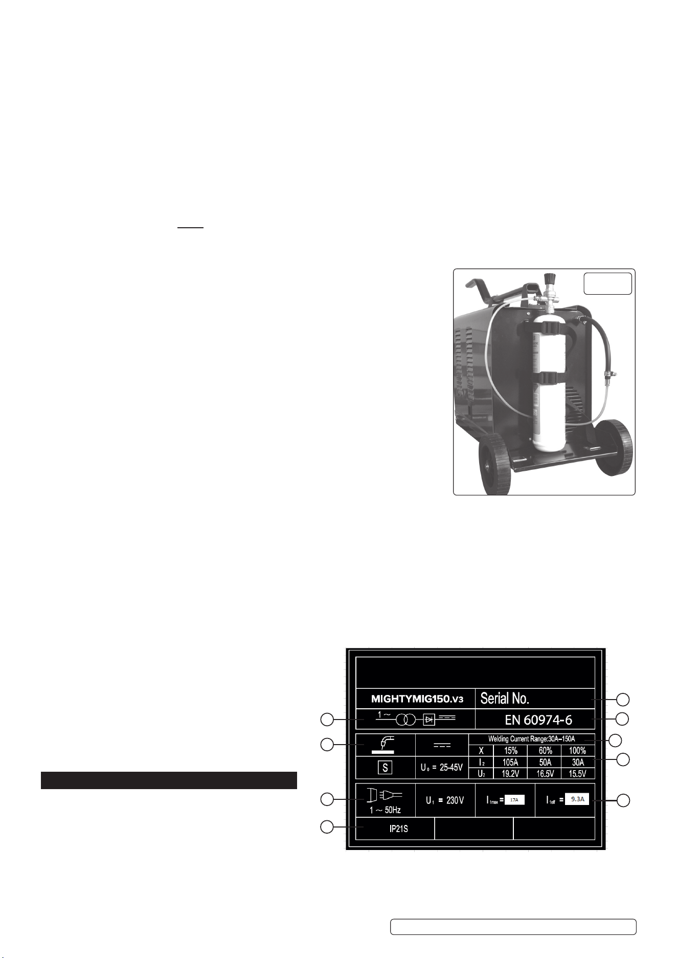
8.5. MOUNT THE GAS CYLINDER
8.5.1. Strap the gas cylinder to the back of the machine. Two nylon straps are provided to hold small cylinders in place. Thread the straps
through the raised metal fixing loops on the back of the welder. Stand the gas cylinder on the rear platform and fix the straps around it as
shown in fig.10.
8.5.2. Close the flow regulator before screwing it onto the cylinder. Screwing down the regulator will automatically open the cylinder valve. When
the sound of gas escaping is heard screw the regulator one further turn only. This will be sufficient to seal the cylinder.
WARNING! Excessive tightening of the flow regulator will over-compress the rubber sealing washer and allow the gas to escape slowly
without being detected.
8.6. CONNECT GAS CYLINDER TO WELDER GAS INPUT. (KIT 120.802032)
8.6.1. Push the small adaptor into one end of the larger diameter hose. Push the other end of
the hose onto the ribbed gas input connector on the back of the welder. Secure both ends
of the hose with the jubilee clips provided. Push one end of the smaller diameter gas hose
into the open end of the adaptor and push the other end into the regulator outlet, it will seal
automatically. See fig10. To release the gas hose, press the collet inwards on the quick
couplers and pull the hose out.
8.6.2. Turn the gas regulator knob halfway for a 2L/min flow and all way for maximum flow of 4L/
min.
8.6.3. Always remove the flow regulator after use if the machine is to be stored for any length of
time.
8.7. GAS TYPES
8.7.1. Welding mild steel with CO
²
gas is appropriate for most welding tasks where spatter
and high build up of weld do not pose a problem. To achieve a spatter-free and flat weld
however, you must use an CO
2
/Argon mixture. To weld aluminium use:
Argon gas 0.8mm Contact Tip 0.8mm Aluminium Wire (MIG/2/KAL08)
8.8. CYLINDER SIZES
8.8.1. The platform at the rear of the welder will support cylinders up to a diameter of 140mm, a
height of 500mm and a maximum weight of 10kg. If you wish to use larger cylinders they
must be properly secured to a separate welding trolley. An industrial gas cylinder adaptor kit will be required. Contact your local Sealey
stockist to order these items. The following table is estimated duration of cylinders based on a flow rate of 2 litres per minute. Actual
duration will be dependant upon various job conditions including the operator’s welding technique. All times are therefore approximate.
Disposable cylinders: CO²/100 390g = 1-1/4hours. CO²/101 600g = 2 hours.
Argon ARG/100 300g = 1hour. Argon/CO
2
MIX/100 300g = 1 hour.
NOTE: When comparing prices, always check fill weights.
8.9. MIG/MAG GAS WELDING PRINCIPLES
8.9.1. Welding wire is automatically fed through an insulated liner to the tip of the torch. The torch consists of a switch, liner, gas hose, and
control cable. The switch activates the wire feed roller and the gas flow. Releasing the switch stops the wire feed and gas flow. The weld
current is transferred to the electrode (the wire) from the
contact tip at the torch end. The current switches (see
section 6.3) control the current to the electrode. Wire
speed must be adjusted according to current output. The
higher the current the faster the wire speed.
A gas cup fits over the contact tip to direct gas flow
towards the weld, ensuring that the arc welding process is
shielded from oxidisation. The shielding gas also assists
heating of the weld. The torch is connected to the positive
side of a DC rectifier, and the negative clamp is attached
to the workpiece.
9. RATINGS PLATE
On the front of the welder is the ratings plate, giving the
Following data:
1. The standard relating to the safety and construction of
arc welding and associated equipment.
2. Single phase transformer - rectifier.
3. Welding with a continuous flow of welding wire.
4. Single-phase AC supply.
5. Rating of internal protection provided by casing.
6. Output
U0: Rated maximum and minimum no load voltage.
9
1
8
6
7
5
4
3
2
fig.
10
Original Language Version
© Jack Sealey Limited
MIGHTYMIG150.V3 Issue:3 (8) 02/11/23
12, U2: Current and corresponding voltage.
X: Welding ratio based on a 10 minute cycle. 20% indicates 2 minutes welding and 8 minutes rest, 100% indicates continuous welding.
7. Welding current range.
8. Mains Supply U1: Rated supply voltage and frequency. I1max: Maximum current. I1eff: Maximum effective current.
9. Serial Number. Specifically identifies each welder.
10. MAINTENANCE
▲ DANGER! Unplug the welder from the mains power supply before performing maintenance or service.
10.1. WIRE FEED UNIT:
10.1.1. Check the wire feed unit at regular intervals. The feed roller wire guide plays an important part in obtaining consistent results. Poor wire
feed affects the weld. Clean the rollers weekly, especially the feed roller groove, removing all dust deposits.
10.2. TORCH
10.2.1. Protect the torch cable assembly from mechanical wear. Clean the liner from the machine forwards by using compressed air. If the liner is
blocked it must be replaced.
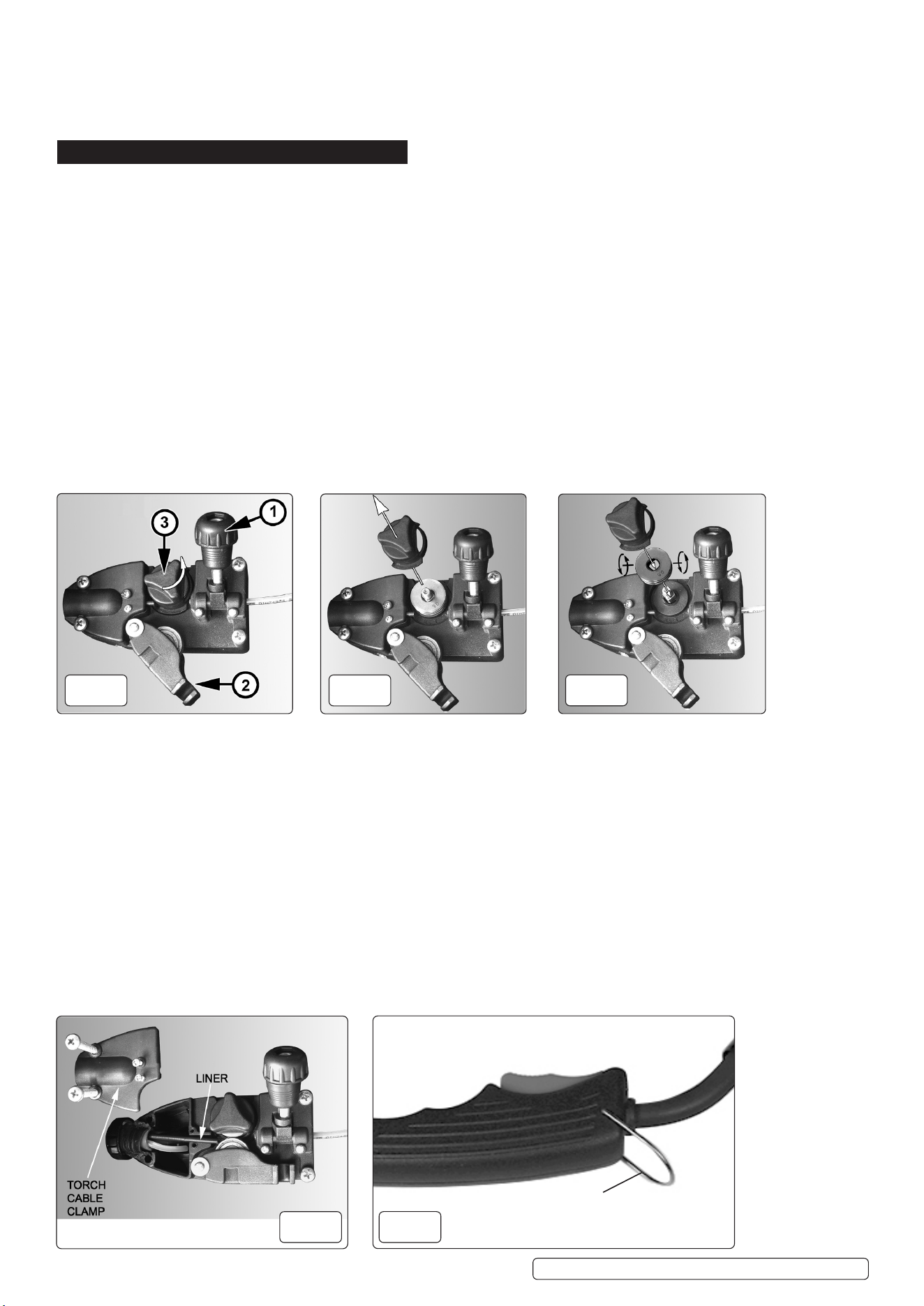
10.3. TURNING FEED ROLLER
IMPORTANT: Turn the feed roller to suit the wire size.
10.3.1. There are two grooves on the feed roller, 0.6mm and 0.8mm. Always have the groove that is being used on the outside of the roller
(nearest to you). To turn the feed roller first loosen the wire tension knob and move it into its up position (see fig.11-1) then move the
tensioning roller assembly to its down position (see fig.11-2). Take hold of the knob on the roller retainer and rotate it 90°anticlockwise to
release it as shown in fig.11-3. Now pull the roller retainer off the drive spindle to reveal the roller as shown in fig.12. Pull the roller off the
drive spindle, flip it over and put it back on the drive spindle (see fig.13). The groove size you require should now be visible printed on the
face of the roller. Push the roller retainer back onto the drive spindle with the opening facing right. Ensure that the flanges at the base of
the retainer, seat fully into the circular recess in the main moulding and then rotate the retainer through 90° to lock it in place.
10.4. CONTACT TIP (to remove tip follow steps in 5.1.8):
10.4.1. The contact tip is a consumable item and must be replaced when the bore becomes enlarged or oval. The contact tip MUST be kept free
from spatter to ensure an unimpeded flow of gas.
10.5. GAS CUP
10.5.1. The gas cup must also be kept clean and free from spatter. Build-up of spatter inside the gas cup can cause a short circuit at the contact
tip which will result in expensive machine repairs. To keep the contact tip free from spatter, we recommend the use of anti-spatter spray
(MIG/722307) available from your Sealey stockist. Refer to fig. 6 for removal and replacement. And 5.1.8 feeding the wire through the
torch.
10.6. REPLACING WIRE LINER
10.6.1. A worn or damaged wire liner will seriously affect the performance of the welder and should be immediately replaced. First wind the wire
back onto the spool and secure it. Remove the four screws securing the torch cable clamp to the wire feed unit (fig.14) and take off the
clamp.
10.6.2. To open the torch case first remove the metal locking ring. See fig.15.
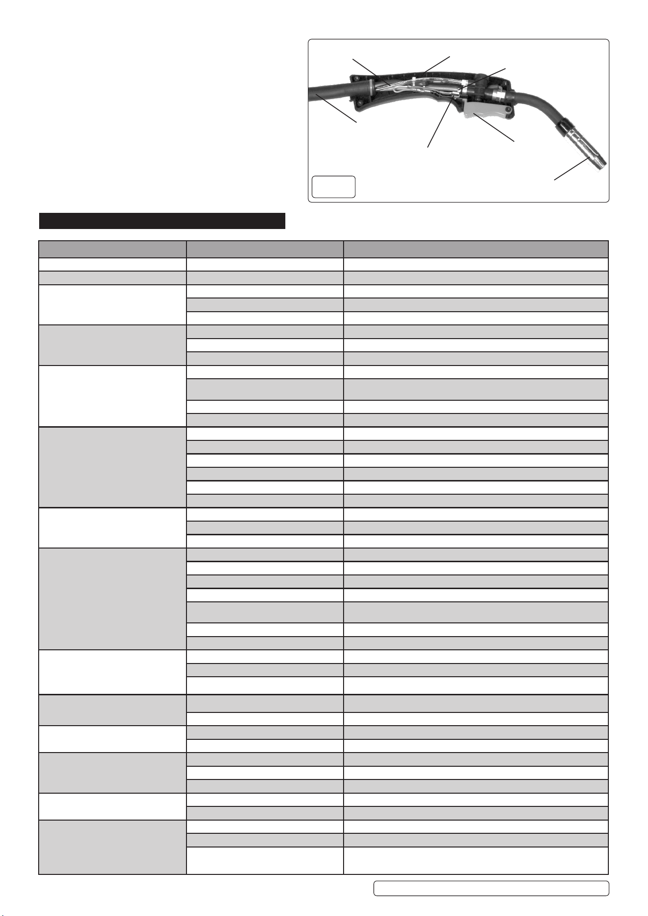
10.6.3. Unscrew the four cross head screws from the torch handle fig.16.
10.6.4. Seperate the two moulding halves away from the inner torch assembly as shown in fig16-4.
10.6.5. Disconnect the blue liner from the torch control assembly by pressing the locking ring into the connector and withdrawing the liner. See fig.14.
10.6.6. With the torch cable as straight as possible unscrew the retaing nut fig16-5 in the torch handle. Pull the liner from the torch cable.
10.6.7. Insert the new liner into the torch cable proceed to feed it through the outer black tube. Secure it in the wire drive unit by replacing the
torch cable clamp. See fig.14. Insert the other end of the liner through the torch fully into the torch control assembly. re-tighten the locking
nut fig 16-5.
fig.
11
fig.
12
fig.
13
fig.
14
Original Language Version
© Jack Sealey Limited
MIGHTYMIG150.V3 Issue:3 (8) 02/11/23
fig.
15
Metal locking ring
10.6.8. Ensure that the switch moulding is fully seated down into
the side moulding. Place the torch head assembly into the
side moulding and arrange the inner connections within
the moulding. The gas pipe and wire liner will rest into
notches on the inner ribs of the moulding. The two thin
switch wires should be below the gas pipe and the larger
blue control cable should be below of the wire liner.
10.6.9. Replace the two mouldings together ensuring that there
are no wires trapped between the two halves. The two
mouldings should close easily, do not force them shut.
10.6.10. Once the mouldings are closed replace the four cross
head screws into the handle, then replace the metal
locking ring.
11. TROUBLESHOOT
PROBLEM POSSIBLE CAUSE
REMEDY
1. Power source stops Overheating protection activated due to overload Protection automatically resets when transformer has cooled (about 15 min)
2. No weld current Rectifier blown Rectifier blown
3. No weld current Bad connection between clamp & workpiece Clean or grind contact surface and weld area
Break in earth lead Repair or replace earth lead.
Break in torch lead Repair or replace torch
4. Feed motor not working, lamp is on Gear damaged or worn Replace gears. (Contact service agent)
Motor defective Replace motor (Contact service agent)
PCB fault Replace PCB
5. Wire does not feed, feed roller rotates Pressure roller improperly adjusted Adjust tension.
Dirt, copper, dust, etc, has collected in torch liner Clean the liner from the machine forward. Use compressed air. If too much dirt, replace
the liner.
Gas cup (Nozzle) or tip defective Replace gas cup (nozzle) and/or tip. (Section 10.5 to 10.5.1)
Deformed wire Check roller tension and adjust it if necessary (Section 5.2)
6. Wire feeds unevenly Dirt, etc, in liner Clean the liner from the machine forward. Use compressed air
Gas cup (Nozzle) or Tip defective Replace gas cup (nozzle) and/or tip. (Section 10.5 to 5.5.1).
Gas cup (Nozzle) spattered Clean or replace gas cup (nozzle) (Section 10.5 to 5.5.1)
Feed roller groove clogged Clean feed roller.
Feed roller groove deformed Replace feed roller.
Pressure roller tension improper Adjust tension. (Section 5.2)
7. Unstable arc Incorrect settings Check settings.
Impurities in weld area Clean and/or grind workpiece.
Worn or defective gas cup (nozzle) Replace gas cup (nozzle). (Section 5.1.8 to 5.1.11)
8. Porous weld No gas Open gas cylinder, regulate gas flow
Gas cup clogged Clean or replace cup. (nozzle) (Section 10.5 to 10.5.1)
Draft blowing away shielding gas Screen off welding site or increase gas flow
Rusty or dirty joints Clean and/or grind workpiece.
Torch too far from or at wrong angle to work The distance from gas cup to workpiece should be 8 to 10mm
Gas leak Check hoses, connections and torch assembly. Press the gas cup into correct position
Faulty electrovalve Clean out or replace
9. Electrode sticking in gas cup (nozzle) Worn or defective gas cup (nozzle) Replace gas cup (nozzle). (Section 10.5 to 10.5.1)
Electrode deformed Check roller tension. (Section 5.2)
Wire speed too slow See recommendations for wire speed
10. Irregular weld head Torch incorrectly held Use correct torch angle
Wire weaving in weld pool Check roller tension and adjust as needed. (Section 5.2)
11. Weld bead too narrow and raised Weld current too low Increase power and wire speed.
Weld speed too high Move torch slower and weave a little more
12. Weld bead too wide Weld current too high
Decrease power and wire speed.
Weld speed too low Move torch faster and weave less
Arc too long Bring torch closer to workpiece
13. Poor penetration Weld current too low Increase power and wire speed.
Arc too long Bring torch closer to workpiece
14. Excessive penetration Weld current too high Decrease power and wire speed.
Weld speed too slow Move torch faster
Incorrect distance of torch to workpiece Torch distance should be 8-10mm
Original Language Version
© Jack Sealey Limited
MIGHTYMIG150.V3 Issue:3 (8) 02/11/23
fig.
16
4. moulding half
5. Wire liner retaining nut
Outer black tube
Trigger
Switch assembly
Gas pipe
Gas cap

Original Language Version
© Jack Sealey Limited
MIGHTYMIG150.V3 Issue:3 (8) 02/11/23
Sealey Group, Kempson Way, Suffolk Business Park, Bury St Edmunds, Suffolk. IP32 7AR
01284 757500 sales@sealey.co.uk www.sealey.co.uk
WEEE REGULATIONS
Dispose of this product at the end of its working life in compliance with the EU Directive on Waste Electrical and Electronic
Equipment (WEEE). When the product is no longer required, it must be disposed of in an environmentally protective way. Contact
your local solid waste authority for recycling information.
NOTE: It is our policy to continually improve products and as such we reserve the right to alter data, specications and component parts
without prior notice.
IMPORTANT: No Liability is accepted for incorrect use of this product.
WARRANTY: Guarantee is 36 months from purchase date, proof of which is required for any claim.
ENVIRONMENT PROTECTION
Recycle unwanted materials instead of disposing of them as waste. All tools, accessories and packaging should be
sorted, taken to a recycling centre and disposed of in a manner which is compatible with the environment. When
the product becomes completely unserviceable and requires disposal, drain any uids (if applicable) into approved
containers and dispose of the product and uids according to local regulations.