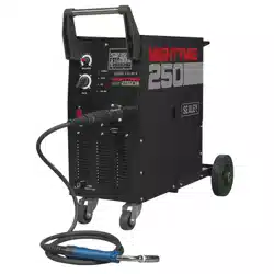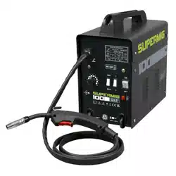
100A NO-GAS MIG WELDER
MODEL NO: SUPERMIG100
Thank you for purchasing a Sealey product. Manufactured to a high standard, this product will, if used according to these instructions,
and properly maintained, give you years of trouble free performance.
IMPORTANT: PLEASE READ THESE INSTRUCTIONS CAREFULLY. NOTE THE SAFE OPERATIONAL REQUIREMENTS, WARNINGS & CAUTIONS. USE
THE PRODUCT CORRECTLY AND WITH CARE FOR THE PURPOSE FOR WHICH IT IS INTENDED. FAILURE TO DO SO MAY CAUSE DAMAGE AND/OR
PERSONAL INJURY AND WILL INVALIDATE THE WARRANTY.
1. SAFETY
1.1. ELECTRICAL SAFETY
WARNING! It is the user’s responsibility to check the following:
9 Check all electrical equipment and appliances to ensure that they are safe before using. Inspect power supply leads, plug and
all electrical connections for wear and damage. Sealey recommend that an RCD (Residual Current Device) is used with all
electrical products.
Electrical safety information. It is important that the following information is read and understood:
9 Ensure that the insulation on all cables and on the appliance is safe before connecting it to the power supply.
9 Regularly inspect power supply cables and plugs for wear or damage and check all connections to ensure that they are secure.
Important: Ensure that the voltage rating on the appliance suits the power supply to be used and that the plug is tted with the correct fuse.
8 DO NOT pull or carry the appliance by the power cable.
8 DO NOT pull the plug from the socket by the cable.
8 DO NOT use worn or damaged cables, plugs or connectors. Ensure that any faulty item is repaired or is replaced immediately
by a qualied electrician.
If the cable or plug is damaged during use, switch o the electricity supply and remove from use.
Ensure that repairs are carried out by a qualied electrician.
1.2. Cable extension reels. When a cable extension reel is used it should be fully unwound before connection. A cable reel with an RCD fitted
is recommended since any product which is plugged into the cable reel will be protected. The section of the cable on the cable reel is
important and should be at least 1.5mm², but to be absolutely sure that the capacity of the cable is suitable for this product and for others
that may be used in the other output sockets, we recommend the use of 2.5mm² section cable.
WARNING! Be very cautious if using a generator to power the welder. The generator must be self-regulating and stable with regard to
voltage, wave form and frequency. The output must be greater than the power consumption of the welder. If any of these requirements is
not met the electronics within the welder may be affected.
NOTE: The use of an unregulated generator may be dangerous and will invalidate the warranty on the welder.
WARNING! The welder may produce voltage surges in the mains supply which can damage other sensitive equipment (e.g.
computers). To prevent this happening, it is recommended that the welder is connected to a power supply that does not feed any
sensitive equipment.
IMPORTANT! If using welder to full capacity, we recommend a 16amp supply. We recommend you discuss the installation of a 16amp
industrial round pin plug and socket with your electrician.
1.3. GENERAL SAFETY
▲ DANGER! Unplug the welder from the mains power supply before performing maintenance or service.
9 Keep the welder and cables in good working order and condition. Take immediate action to repair or replace damaged parts.
9 Use genuine parts and accessories only. Unapproved parts may be dangerous and will invalidate the warranty.
9 Use an air hose to regularly blow out any dirt from the liner and keep the welder clean for best and safest performance.
9 Check and spray the gas cup and contact tip regularly with anti-spatter spray, available from your Sealey stockist.
9 Locate welder in a suitable work area. Ensure that the area has adequate ventilation as welding fumes are harmful.
9 Keep work area clean, tidy and free from unrelated materials. Also ensure the working area has adequate lighting and that a fire
extinguisher is at hand.
WARNING! Use welding head shield to protect eyes and avoid exposing skin to ultraviolet rays given off by electric arc. Wear
safety welding gauntlets.
Refer to
instruction
manual
Wear a
welding
mask
Wear protective
gloves
Warning!
Electricity
Shock hazard
Warning!
Keep away
from rain
Caution
required
Arc rays can
burn eyes and
injure skin
Breathing
welding fumes
can be
hazardous to
your health
Electric shock
from welding
electrodes can
kill
Electromagnetic
fields can cause
pacemaker
malfunction
Welding sparks
can cause
explosions
or fire
Original Language Version
© Jack Sealey Limited
SUPERMIG100 Issue 3 (1) 24/10/23
9 Remove ill fitting clothing, remove ties, watches, rings and other loose jewellery and contain long hair.
9 Ensure the workpiece is correctly secured before welding.
9 Avoid unintentional contact with the workpiece. Accidental or uncontrolled use of the torch may be dangerous and will wear the nozzle.
9 Keep unauthorised persons away from the work area. Any persons working within the area must wear a protective head shield and gloves.
9 Operators must receive adequate training before using the welder.
9 Stand correctly keeping a good footing and balance, ensure the floor is not slippery and wear non-slip shoes.
8 DO NOT operate the welder if it or the cables are damaged and DO NOT attempt to fit any unapproved torches or other
components to the welder.
8 DO NOT get welder wet or use in damp or wet locations or areas where there is condensation.
▲ DANGER! DO NOT weld near flammable solids, liquids or gases and DO NOT weld containers or pipes which have held
flammable materials. Avoid welding materials which have been cleaned with chlorinated solvents or welding near such solvents.
8 DO NOT stand welder on a metal workbench, car bodywork or similar.
8 DO NOT touch any live metal parts of the torch or electrode while the machine is switched on.
8 DO NOT pull the welder by the cable, or the torch. Protect cables from sharp or abrasive items. DO NOT bend, strain or stand on cables
or leads.
9 Protect from heat. Long lengths of slack must be gathered and neatly coiled. DO NOT place cables where they endanger others.
8 DO NOT touch the torch or workpiece immediately after welding as they will be very hot. Allow to cool.
8 DO NOT operate welder while under the influence of drugs, alcohol or intoxicating medication, or if tired.
9 When not in use store the welder in a safe, dry, childproof area.
2. INTRODUCTION
IMPORTANT: These instructions contain the information you require to prepare your machine for welding, together with a maintenance
and a troubleshooting section. The instructions are not intended to teach you how to weld. If you have no experience, we recommend that
you seek training from an expert source. MIG welding is relatively easy, but does require a steady hand and supervised practice on scrap
metal, as it is only with continued practice that you will achieve the desired results.
One of our SUPERMIG® range, this compact no-gas welder offers excellent performance at an extremely competitive price. High output
transformer and forced-air cooling to maximize duty cycle performance. Supplied with 2m live torch and 1.4m earth cable. Suitable for
gasless operation only. For use with flux cored wire only.
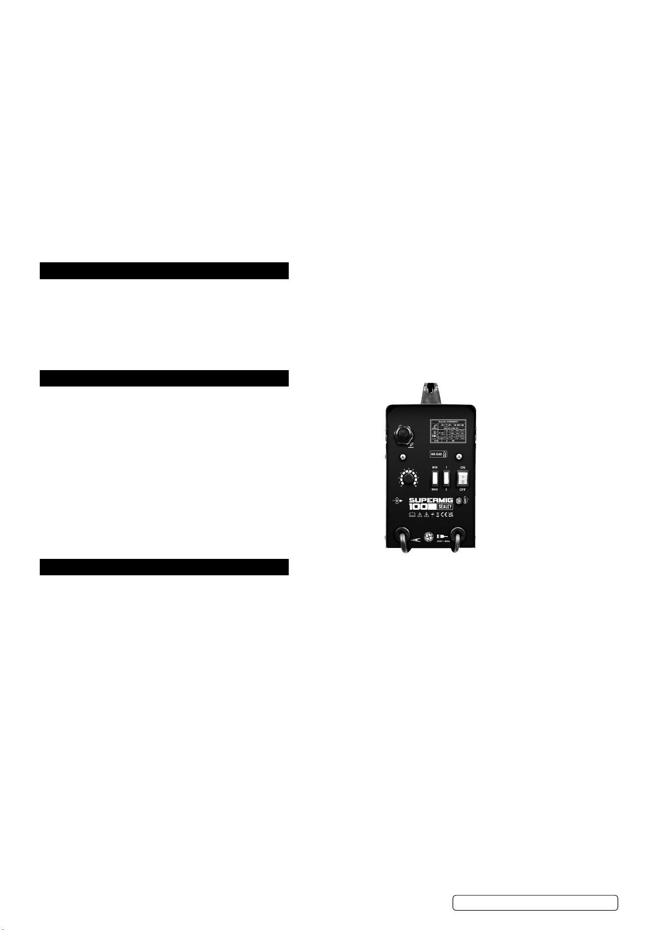
3. SPECIFICATION
Model No: ................................................ SUPERMIG100
Welding Current: ................................................40 - 100A
Wire Capacity: ........................................1kg Gasless only
Duty Cycle: .......100% @ 32A, 35% @ 54A, 10% @ 100A
Cooling System: ................................................Forced Air
Spot Welding Timer: ......................................................No
Gas Type: ..................................................................... N/A
Torch: ..........................................................................Live
Supply: ............................................................. 230V-13A*
Absorbed Power: ..................................................... 3.3kW
Case Size: ...........................................................Compact
*Note: To achieve maximum power a 32A supply may be required.
4. ASSEMBLY
4.1. FIT HANDLE: Slide handle onto top cover. Secure with screw (19), see Parts Diagram.
4.2. FIT COVER LOCKING SPRING: Fix Cover Locking Spring (8), see Parts Diagram, to top of front panel. Use screw, washer and spring
washer supplied. See also g.1.A.
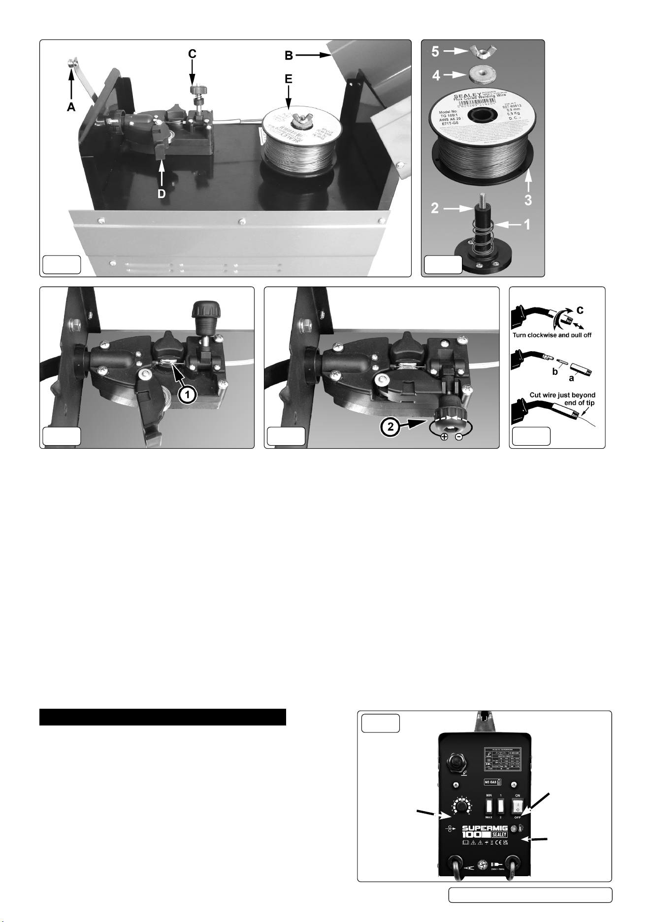
4.3. FITTING A REEL OF WIRE
4.3.1. Depress the silver button in the front of the handle and open the top compartment. See A & B in g.1.
4.3.2. Referring to g.2, rotate the buttery nut (5) anti-clockwise and remove it from the threaded spindle together with the pressure disc (4).
Leave the spring (1) on the spindle (2).
4.3.3. Place the wire reel (3) over the spindle and down onto the spring ensuring that the wire will withdraw from the spool in a forwards
direction and on the same side of the compartment as the wire feed unit.
4.3.4. Push lightly down on the top of the reel of wire and screw the pressure disc (4) onto the end of the spindle and down onto the top of the
wire reel. The reel take o pressure should be set to provide a mild braking eect to prevent overrun where loose coils of wire form on
the reel. DO NOT over tighten the pressure disc as too much braking will conict with the wire tension set on the wire drive unit.
4.3.5. Lock the position of the pressure disc by screwing the buttery nut (5) down on top of it.
4.3.6. Referring to g.1 turn the knob on the wire lock screw (C) anti-clockwise and lift it up and away from the pressure roller moulding.
4.3.7. Swing the pressure roller moulding (D) away from the drive roller.
4.3.8. Release the wire from the spool (DO NOT allow wire to uncoil) and straighten 40-50mm of wire and gently push through the exible
plastic guide and through the same size groove on the feed roller as the wire you choose to use.
Original Language Version
© Jack Sealey Limited
SUPERMIG100 Issue 3 (1) 24/10/23
g.1 g.2
g.5g.3 g.4
4.3.9. Referring to g.4, move the pressure roller moulding back round onto the grooved drive wheel and swing
down the wire lock screw to lock it in place. See section 4.3 regarding wire tension.
4.3.10. Feeding the wire through to the torch. (See g.5) Remove gas cup (a) and contact tip (b) from end of torch as follows:
a) Take torch in left hand with the torch tip facing to the right.
b) Grasp gas cup rmly in your right hand.
c) Turn gas cup clockwise only and pull cup out to the right.
WARNING! DO NOT turn gas cup anti-clockwise, as this will damage internal spring.
d) Unscrew the copper contact tip (g.5.b) (right hand thread) to remove.
4.3.11. Check welder is switched OFF and that the earth clamp is away from the torch tip. Connect the welder to the mains power supply and
set the voltage switch to MIN.
4.3.12. Set the wire speed knob to position 5 or 6. Keeping the torch cable as straight as possible and press the torch switch. The wire will
feed through the torch.
4.3.13. When wire has fed through, switch welder o, unplug from mains.
a) Take torch in left hand, slide the contact tip over the wire and screw it back into place.
b) Grasp gas cup in right hand, push onto torch head and turn clockwise only.
WARNING! DO NOT turn gas cup anti-clockwise, as this will damage internal spring.
c) Cut wire so that it is just protruding from the cup.
4.4. SETTING WIRE TENSION
IMPORTANT: You must set the correct tension, too little or too much tension will cause problematic wire feed and result in a poor weld.
4.4.1. Correct tension between the rollers is checked by slowing down the wire between gloved ngers. If the pressure roller skids the tension
is correct. Try to use the lowest tension possible as too high a tension will deform the wire. When you have completed welding allow
the welder to cool before storing in a safe, dry place. Note: Damaged torches and cables are not covered under warranty.
5. WELDING PRINCIPLES
IMPORTANT: These instructions are not intended to teach you how to
weld. If you have no experience, we recommend that you seek training
from an expert source. MIG welding is relatively easy, but does require
a steady hand and supervised practice on scrap metal, as it is only
with continued practice that you will achieve the desired results.
5.1. MIG/MAG WELDING
5.1.1. Welding wire is automatically fed through an insulated liner to the tip
of the torch. The torch consists of a switch, liner, and control cable.
The switch activates the wire feed roller. Releasing the switch stops
wire feed. The weld current is transferred to the electrode (the wire)
from the contact tip at the torch end. The current to the electrode is set
using the rocker switch on the front of the control panel.
g.6
POWER
THERMAL
OVERLOAD
WIRE
SPEED
Original Language Version
© Jack Sealey Limited
SUPERMIG100 Issue 3 (1) 24/10/23
Wire speed must be adjusted according to current output using the rotary control positioned to the left of the control panel. The higher
the current the faster the wire speed.
5.2. PREPARATION FOR WELDING
IMPORTANT! BEFORE YOU COMMENCE, MAKE SURE THE MACHINE IS SWITCHED OFF AT THE MAINS. IF WELDING A CAR,
DISCONNECT THE BATTERY OR FIT AN ELECTRONIC CIRCUIT PROTECTOR. ENSURE THAT YOU READ, UNDERSTAND AND
APPLY THE SAFETY INSTRUCTIONS IN SECTION 1.
5.2.1. To ensure a complete circuit, the negative lead must be securely attached to the workpiece close to the weld area. Best connection is
obtained by grinding the point of contact on the workpiece before connecting the clamp.
5.2.2. The weld area must be free of paint, rust, grease, etc.
5.3. THERMAL PROTECTION
5.3.1. Should the welder become overheated due to prolonged use beyond the stated duty cycle the thermal protection will cause the welder
to cut out and the orange light on the front panel will illuminate. Wait for fifteen minutes for the welder to cool down at which time it will
reconnect automatically.
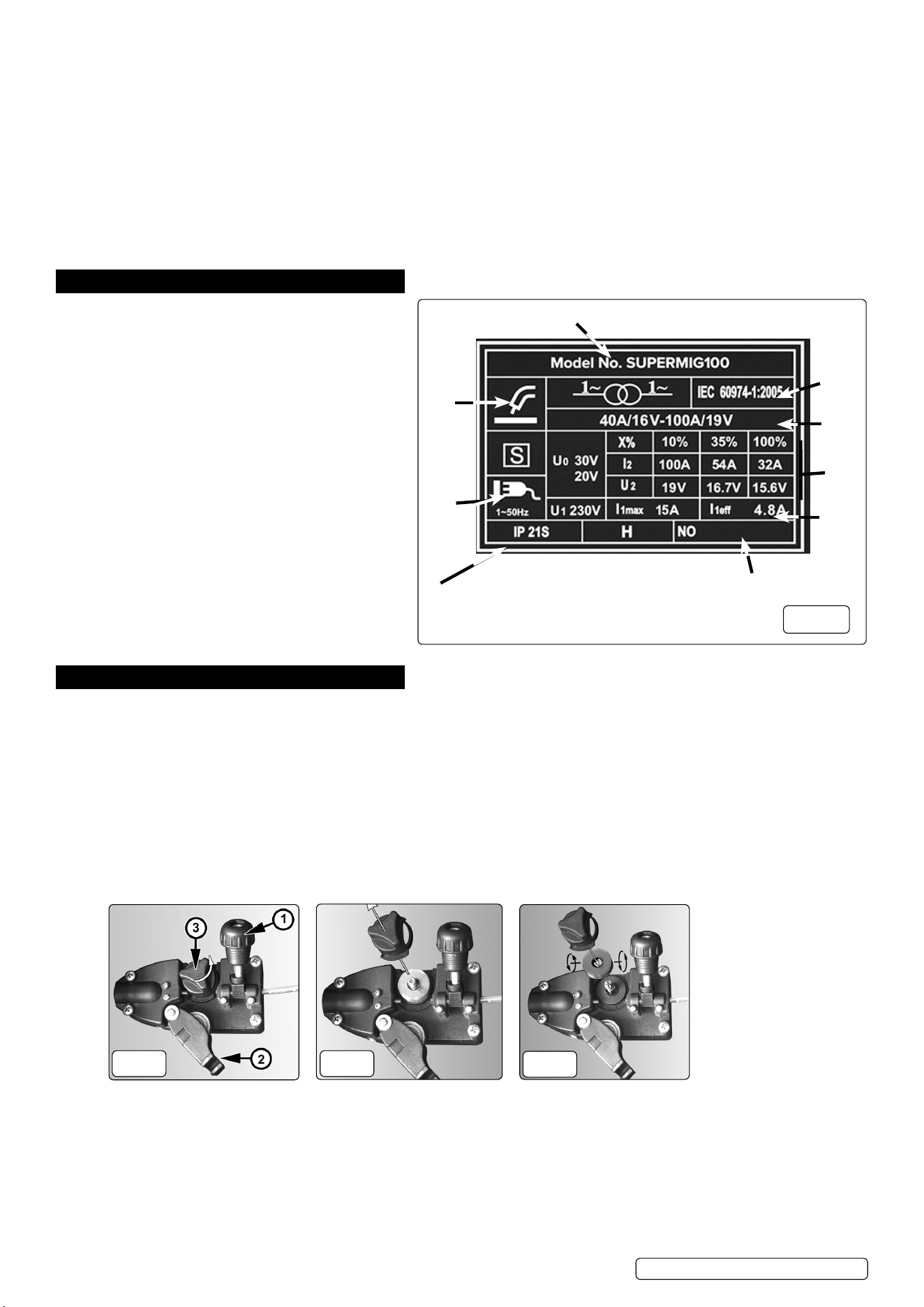
6. RATINGS PLATE
On the front panel of the welder is the ratings plate,
giving the following data:
1 - The BS/EU standard relating to the safety and
construction of arc welding and associated equipment.
2 - Single phase transformer.
3 - Symbol indicates welding with a continuous flow of
welding wire.
4 - Symbol for Single-phase AC supply.
5 - Rating of internal protection provided by casing.
6 - Output U0 Rated minimum and maximum no load
voltage.
I2, U2 Current and corresponding voltage.
X Welding ratio based on a 10 minute cycle.
20% indicates 2 minutes welding and 8
minutes rest,
100% would indicate continuous welding.
7 - Mains Supply U1 Rated supply voltage and
frequency.
I1max Maximum current.
I1eff Maximum effective current.
8 - Welding current range.
9 - Serial Number. Specifically identifies each welder.
7. MAINTENANCE
▲ DANGER! Unplug the welder from the mains power supply before performing maintenance or service.
7.1. WIRE FEED UNIT
7.1.1. Check the wire feed unit at regular intervals. The feed roller wire guide plays an important part in obtaining consistent results. Poor wire
feed affects the weld. Clean the rollers weekly, especially the feed roller groove, removing all dust deposits.
7.2. TORCH
7.2.1. Protect the torch cable assembly from mechanical wear. Clean the liner from the machine forwards by using compressed air. If the liner is
blocked it must be replaced.
7.3. TURNING FEED ROLLER IMPORTANT: TURN THE FEED ROLLER TO SUIT THE WIRE SIZE.
7.3.1. There are two grooves on the feed roller, 0.8mm and 1mm. Always have the groove that is being used on the outside of the roller (nearest
to you). To turn the feed roller first loosen the wire tension knob and move it into its up position (see fig.8-1) then move the tensioning
roller assembly to its down position (see fig.8-2). Take hold of the triangular knob on the roller retainer and rotate it 90°anticlockwise to
release it as shown in fig.8.3. Now pull the roller retainer off the drive spindle to reveal the roller as shown in fig.9.
g.8
g.9
g.10
7.3.2. Pull the roller off the drive spindle, flip it over and put it back on the drive spindle. (See fig.10) The groove size you require should now be
visible on the face of the roller. Push the roller retainer back onto the drive spindle with the opening facing right. Ensure that the flanges at
the base of the retainer, seat fully into the circular recess in the main moulding and then rotate the retainer through 90° to lock it in place.
7.4. CONTACT TIP (to remove tip follow steps in 4.3.10.):
7.4.1. The contact tip is a consumable item and must be replaced when the bore becomes enlarged or oval. The contact tip MUST be kept free
from spatter.
g.7
3
1
6
5
4
7
8
2
9
Original Language Version
© Jack Sealey Limited
SUPERMIG100 Issue 3 (1) 24/10/23
7.5. GAS CUP (to remove cup follow steps in 4.3.10.):
7.5.1. The gas cup must also be kept clean and free from spatter. Build-up of spatter inside the gas cup can cause a short circuit at the contact
tip which will result in expensive machine repairs. To keep the contact tip free from spatter, we recommend the use of anti-spatter spray
(MIG/722308) available from your Sealey stockist.
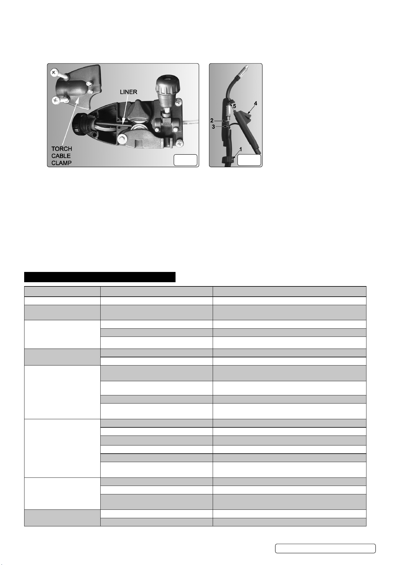
7.6. REPLACING WIRE LINER
g.11
g.12
7.6.1. A worn or damaged wire liner will seriously affect the performance of the welder and should be immediately replaced. First wind the wire
back onto the spool and secure it. Remove the four screws securing the torch cable clamp to the wire feed unit (fig.11) and take off the
clamp.
7.6.2. Open the torch case by gripping the torch with one hand and turning the grooved ring at the base of the torch anticlockwise until it stops,
then pull it off the torch onto the torch cable. See fig.12-1.
7.6.3. Take hold of the back end of the moulding which contains the switch and pull it outwards and downwards to release it from the other
moulding as shown in fig.12.
7.6.4. Push the liner lock ring (2) firmly towards the brass nut and withdraw the liner from the nut. With the torch cable as straight as possible pull
the liner from the torch cable.
7.6.5. Insert the new liner into the torch cable and secure it in the wire drive unit by replacing the torch cable clamp. See fig.11. Insert the other
end of the liner through the locking ring and fully into the brass nut in the torch head, see 2 in fig.12.
7.6.6. Check that the torch inner parts are properly seated in their respective mouldings then close the torch by inserting the tongue on the
switch moulding (fig.12-5) into the slot at the front of the other moulding. Swing the switch moulding downwards and forwards until both
parts have closed around the torch cable. Slide the ribbed ring (fig.12-1) onto the end of the torch handle turn it clockwise to lock.
8. TROUBLESHOOTING
PROBLEM POSSIBLE CAUSE REMEDY
Weld current interrupted Overheating protection activated due to overload Protection automatically resets when transformer has cooled (approx. 15 min)
No weld current Rectifier blown Replace rectifier
No weld current Bad connection between clamp and workpiece Clean or grind contact surface and weld area
Break in earth lead Repair or replace earth lead
Break in torch lead Repair or replace
Feed motor not working Gear damaged or worn Replace gears
Motor defective Replace motor (Contact service agent)
Wire does not feed, feed roller rotates Pressure roller improperly adjusted Adjust tension
Dirt, copper, dust, etc. have collected in torch liner Clean the liner from the machine forward. Use compressed air.
Gas cup (nozzle) or tip defective Replace gas cup (nozzle) and/or tip. Check roller tension
Deformed wire Adjust roller tension
Wire feeds unevenly Dirt, etc, in liner Clean the liner from the machine forward using compressed air
Gas cup (nozzle) or tip defective Replace gas cup (nozzle) and/or tip
Gas cup (nozzle) spattered Clean or replace gas cup (nozzle)
Feed roller groove clogged Clean feed roller
Feed roller groove deformed Replace feed roller
Pressure roller tension incorrect Adjust tension
Unstable arc Incorrect settings Check settings
Impurities in weld area Clean and/or grind workpiece
Worn or defective gas cup (nozzle) Replace gas cup (nozzle)
Porous weld Rusty/dirty joints Clean or grind the workpiece
Torch too far from, or at wrong angle to, workpiece Gas cup to workpiece should be 8-10mm. Torch angle approx 75°
g.11
Original Language Version
© Jack Sealey Limited
SUPERMIG100 Issue 3 (1) 24/10/23
Sealey Group, Kempson Way, Suffolk Business Park, Bury St Edmunds, Suffolk. IP32 7AR
01284 757500 sales@sealey.co.uk www.sealey.co.uk
Note: It is our policy to continually improve products and as such we reserve the right to alter data, specifications and component parts without prior
notice. Please note that other versions of this product are available. If you require documentation for alternative versions, please email or call
our technical team on technical@sealey.co.uk or 01284 757505.
Important: No Liability is accepted for incorrect use of this product.
Warranty: Guarantee is 36 months from purchase date, proof of which is required for any claim. Lifetime guarantee on Transformer.
WEEE REGULATIONS
Dispose of this product at the end of its working life in compliance with the EU Directive on Waste Electrical and Electronic Equipment
(WEEE). When the product is no longer required, it must be disposed of in an environmentally protective way. Contact your local solid
waste authority for recycling information.
Wire sticking in gas cup (nozzle) Worn or defective gas cup (nozzle) Replace gas cup (nozzle)
Wire deformed Check roller tension
Wire speed too slow Increase wire speed
Irregular weld head Torch incorrectly held Use correct torch angle
Wire weaving in weld pool Check roller tension and adjust
Weld bead too narrow and raised Weld current too low Increase power and wire speed
Weld speed too fast Move torch slower and weave a little more
Weld bead too wide Weld current too high Increase power and wire speed
Weld speed too slow Move torch faster and weave less
Poor penetration Weld current too low Increase current and wire speed
Arc too long Bring torch closer to workpiece
Excessive penetration Weld current too high Decrease current and wire speed
Weld current too slow Decrease current and wire speed
Incorrect distance of torch to workpiece Torch distance should be 8-10mm
Original Language Version
© Jack Sealey Limited
SUPERMIG100 Issue 3 (1) 24/10/23
ENVIRONMENT PROTECTION
Recycle unwanted materials instead of disposing of them as waste. All tools, accessories and packaging should be
sorted, taken to a recycling centre and disposed of in a manner which is compatible with the environment. When
the product becomes completely unserviceable and requires disposal, drain any uids (if applicable) into approved
containers and dispose of the product and uids according to local regulations.
REGISTER YOUR
PURCHASE HERE