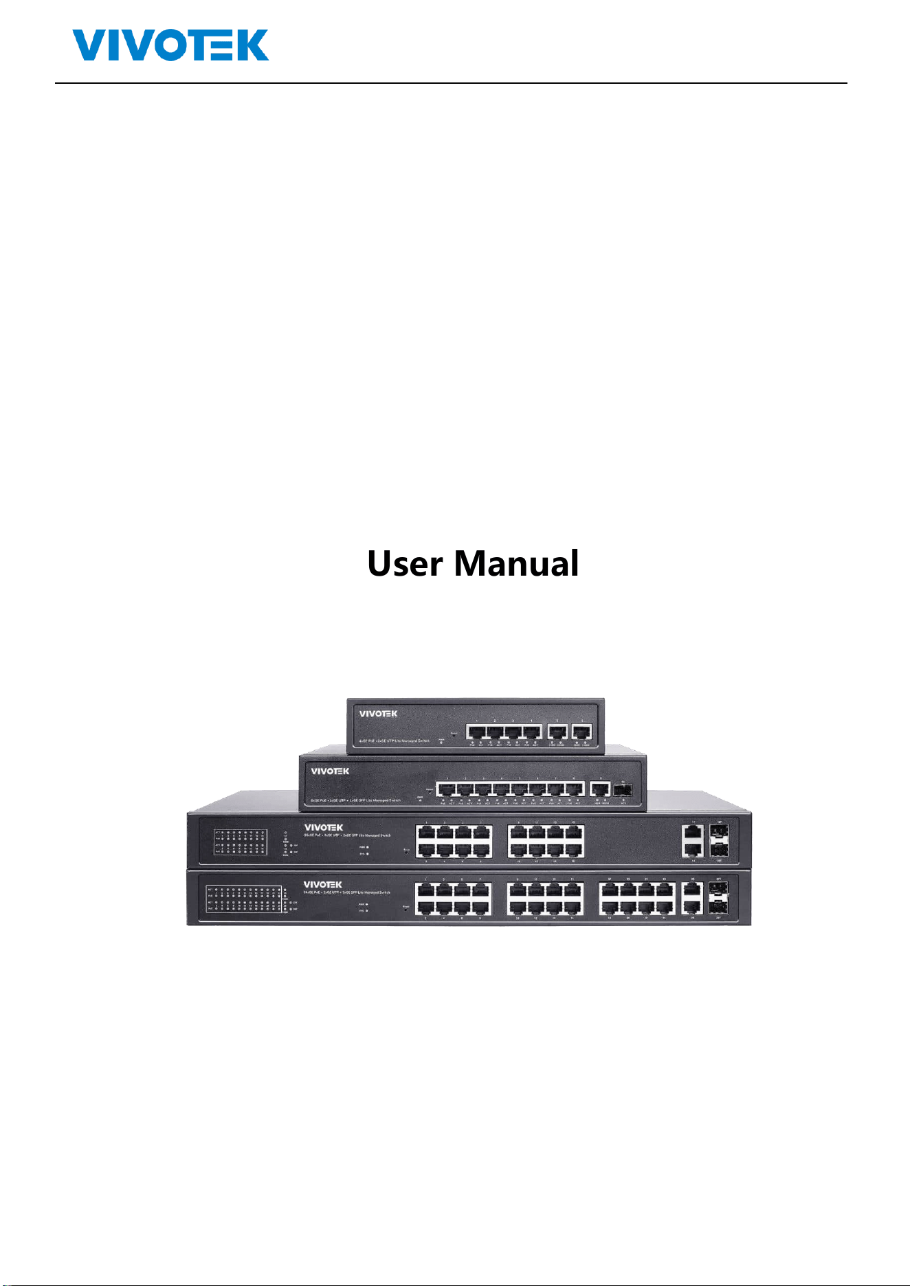

Lite Management PoE Switch Series User Guide
Revision History:
Version
Date
Revision History
V1.0
2022.06
New first edition

Lite Management PoE Switch Series User Guide
Content
Content ........................................................................................................................................................................... 3
1. Log In ....................................................................................................................................................................... 4
1.1. Log into web interface .............................................................................................................................. 5
1.2. Web-based user interface ........................................................................................................................ 6
2. System .................................................................................................................................................................... 7
2.1. Information ............................................................................................................................................... 7
2.2. IP Setting ................................................................................................................................................... 8
2.3. User Account ............................................................................................................................................. 8
3. VLAN ....................................................................................................................................................................... 9
3.1. Static VLAN................................................................................................................................................ 9
3.2. VLAN Setting ........................................................................................................................................... 10
4. MAC Address ........................................................................................................................................................ 11
4.1. MAC Search ............................................................................................................................................. 11
4.2. Static MAC............................................................................................................................................... 11
5. PoE ........................................................................................................................................................................ 12
5.1. PoE Management ................................................................................................................................... 12
6. Port ....................................................................................................................................................................... 14
6.1. Port Management ................................................................................................................................... 14
6.2. Port Statistics .......................................................................................................................................... 15
6.3. Storm Control ......................................................................................................................................... 15
6.4. Port-based Mirroring .............................................................................................................................. 16
6.5. Port Isolation........................................................................................................................................... 16
6.6. Bandwidth Control .................................................................................................................................. 17
7. STP ........................................................................................................................................................................ 18
7.1. STP General ............................................................................................................................................. 18
7.2 STP Config ............................................................................................................................................... 19
8. QoS ........................................................................................................................................................................ 20
8.1. Dscp remapping ...................................................................................................................................... 20
8.2. Priority to Queue .................................................................................................................................... 20
8.3. Port-based Priority .................................................................................................................................. 21
9. Link Aggregation ................................................................................................................................................... 22

Lite Management PoE Switch Series User Guide
9.1. Trunk Group Setting ................................................................................................................................ 22
10. Maintenance ................................................................................................................................................. 23
10.1. Firmware Upgrade .................................................................................................................................. 23
10.2. Reset ....................................................................................................................................................... 24
10.3. Save ......................................................................................................................................................... 24
10.4. Reboot .................................................................................................................................................... 24
1. Log In
Lite Management PoE Switch Series User Guide
1.1. Log into web interface
The switch can be managed by entering the IP address of the device in the browsers (installed on
your computer). The URL format in the address bar is:
Note: The default factory IP address, username and password are as below.
IP Address
DHCP Client
Username
admin
Password
admin
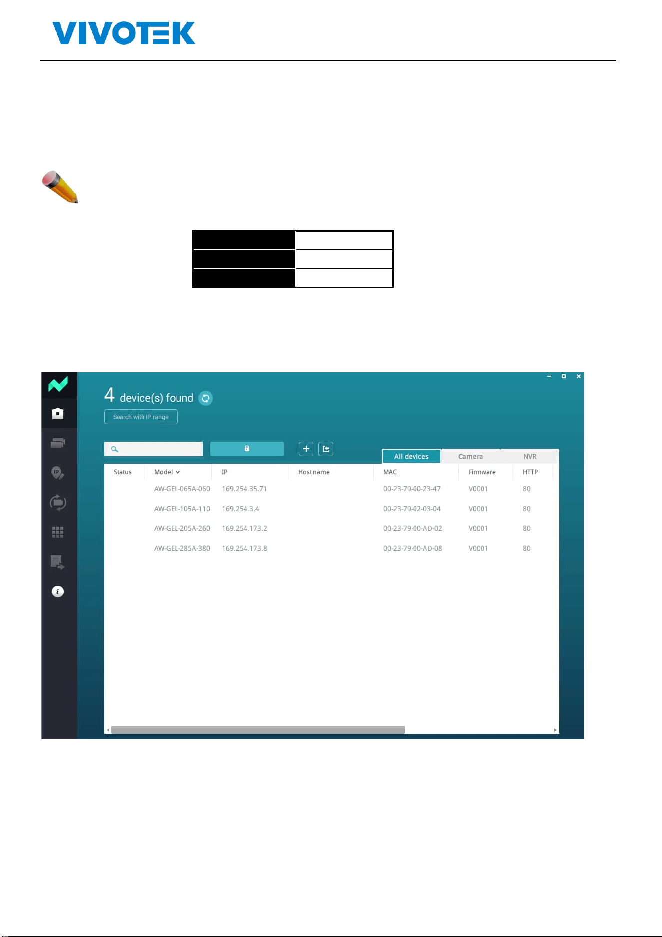
As the default network setting is DHCP client, so If you do not have DHCP server to provide ip
address to the switch, You can find the switches by using VIVOTEK’s Shepherd utility.
The logging window for user as following:
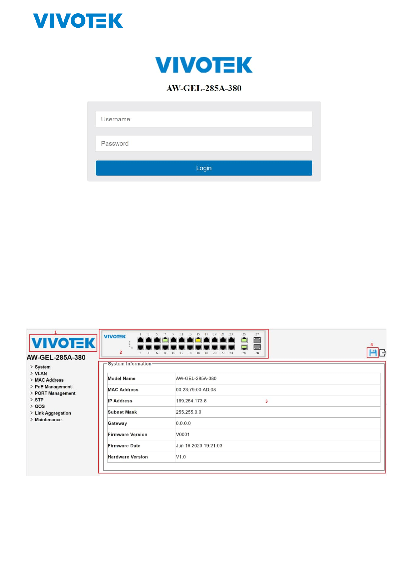
Lite Management PoE Switch Series User Guide
Picture 1-1Enter user name and password
Default Username and password are admin/ admin,Enter and clik“OK”,open the management
interface
1.2. Web-based user interface
The user interface provides access to different configuration and management windows, allowing
users to view performance statistics and monitor system status. The user interface is divided into three
distinct areas as in following picture
Picture 1-2 Web Interface
Lite Management PoE Switch Series User Guide
Area
Function
Area 1
VIVOTEK LOGO: When you click VIVOTEK logo, it will bring a browser to VIVOTEK website.
Area 2
Port status: It will show the port status. When the port shows green, it means link up with
1000 mbps speed. When the port shows in amber, it means link up with 10/100 mbps speed.
Area 3
According to the user selection (area 3), it shows the switch information
Area 4
The disk icon will become bule after you change the settings.
Please make sure to click to save configuration after you change the settings
otherwise the settings that you change will be gone after switch rebooting.
2. System
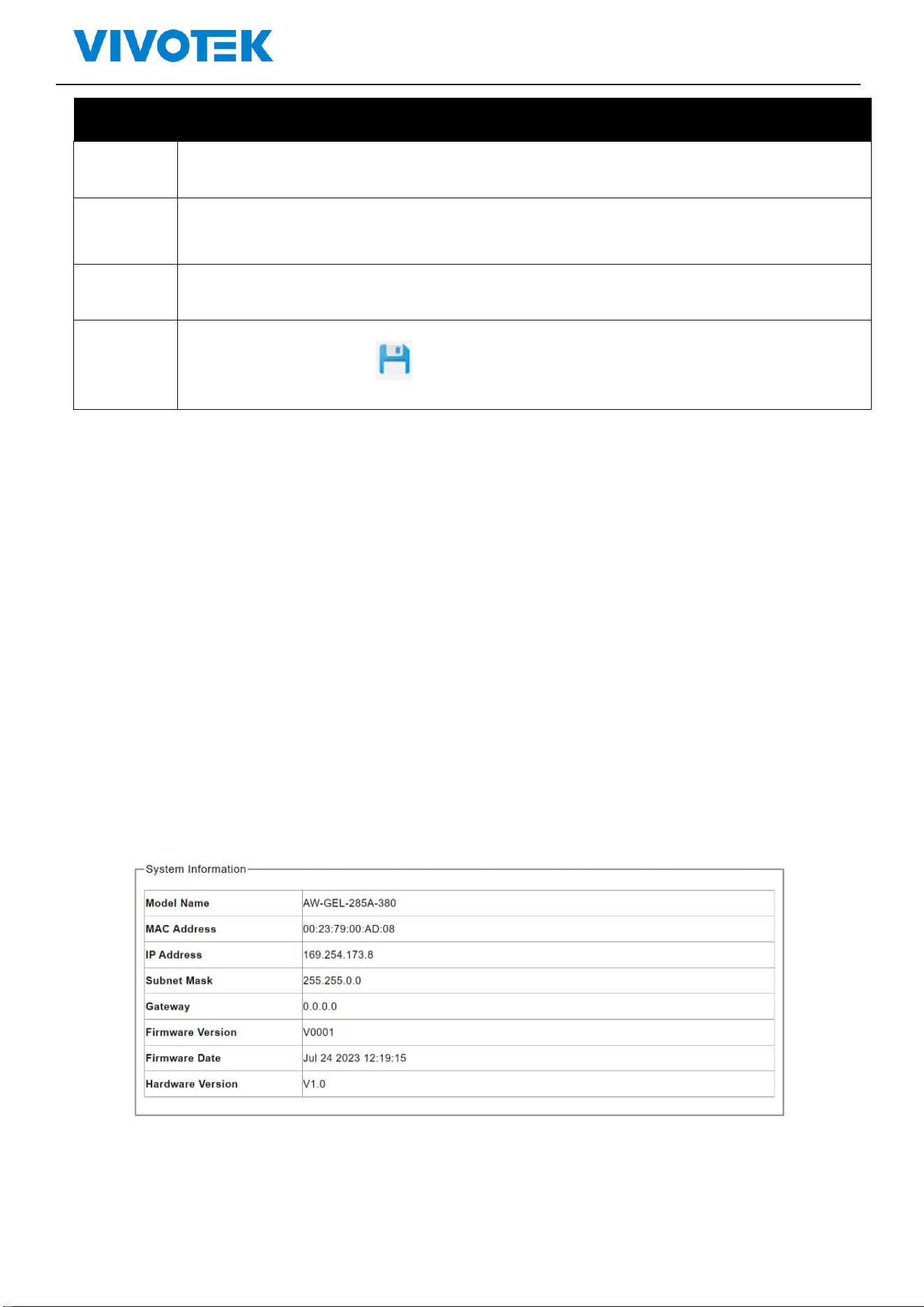
2.1. Information
Users can view the basic information of the switch, such as the managed IP address, Mac address, firmware
version.
Click“system”>“information” ,shown as following:
Picture 2-1 System information
Lite Management PoE Switch Series User Guide
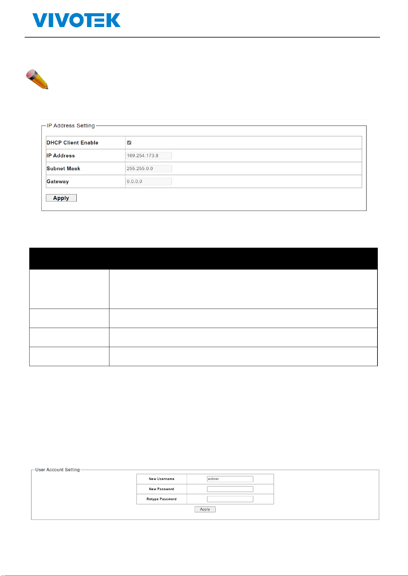
2.2. IP Setting
Note: The factory default IP address of the switch is DHCP Client
Click“system”>“ IP Setting”,Shown as following:
Picture 2-2 IP Setting
The description of IP Setting:
Parameters
Description
DHCP
- -If it is enabled, it means that the IPv4 DHCP client is enabled on the
VLAN interface to dynamically obtain the IPv4 address of the switch,
- If it is disabled, the static IP configuration of the switch is used
IP Address
- The user IP address
Subnet Mask
- The static subnet mask
Gateway
- The user gateway IPv4 address
Enter the new management IP address. Click Apply for saving the changes
2.3. User Account
You can modify the login username and password
Click“system”>“User Account”,shown as following:
Picture 2-4 User Account Setting
Lite Management PoE Switch Series User Guide
Description:
Parameters
Description
New Username
Enter the new user name
New Password
Enter the new password
Retype Password
Retype the new password
Click Apply for saving the changes.
3. VLAN
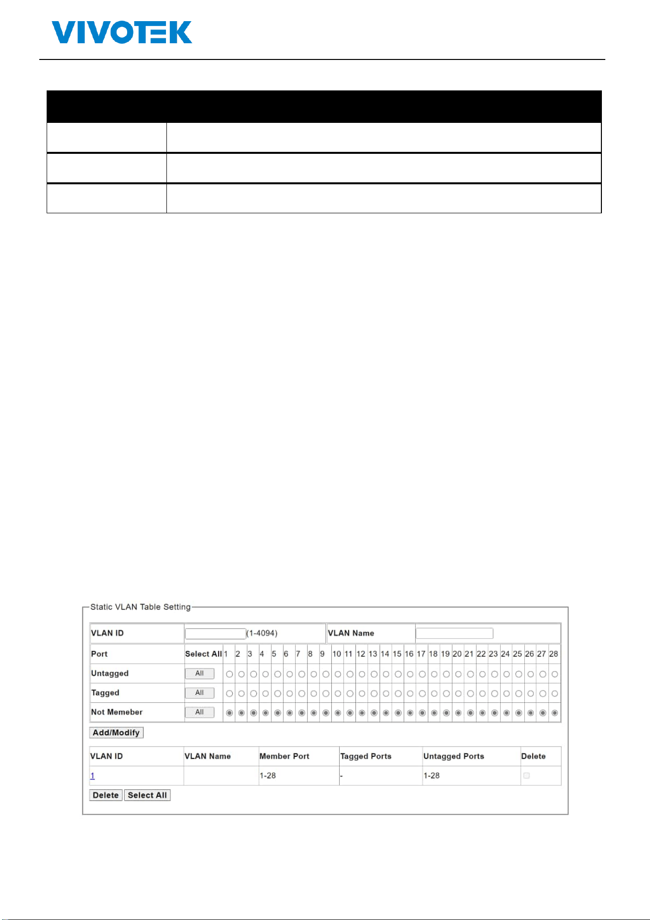
3.1. Static VLAN
This page is used to configure VLANs
Click“VLAN”>“Static VLAN”, shown as following:
Picture 3-1 static vlan setting
Lite Management PoE Switch Series User Guide
Description:
Parameters
Description
VLAN ID
Enter VLAN ID 1-4094
PORT
Choose the configuration port
Untagged
Click to choose untagged member port
Tagged
Click to choose tagged member port
Not Member
Click to choose Not Member port
Click “Add”for saving the changes
Click “Delete”for saving the changes
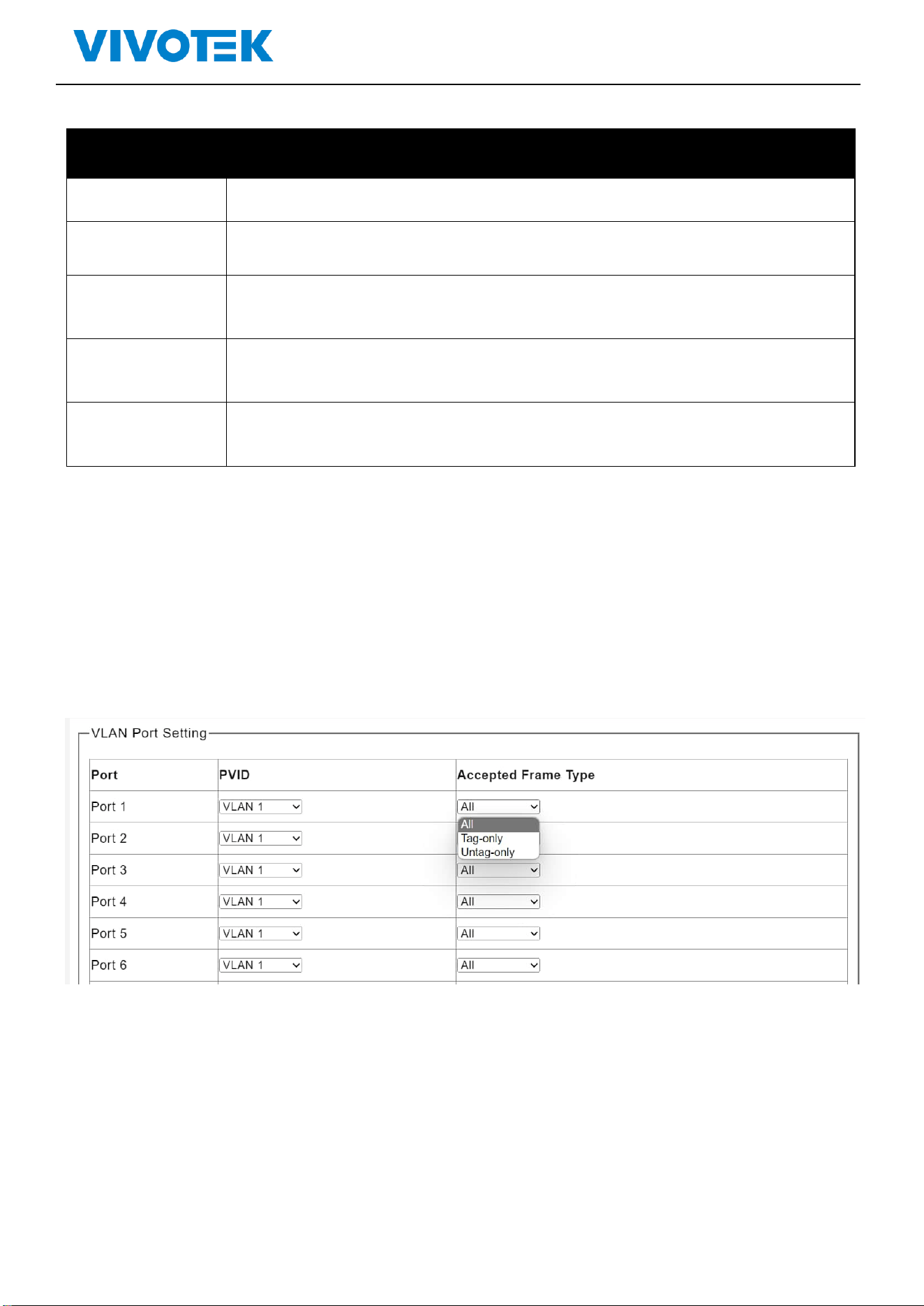
3.2. VLAN Setting
The page is used to configure VLAN。
Click”Configuration”>“VLAN”>“VLAN setting”, shown as following:
Picture 3-1 VLAN Setting
Lite Management PoE Switch Series User Guide
Description:
Parameter
Description
PVID
Enter VLAN ID 1-4094
PORT
Choose the port for configuration
Accepted Frame Type
Choose all, tag-only or untagged-only
Click“Apply”for saving changes
4. MAC Address
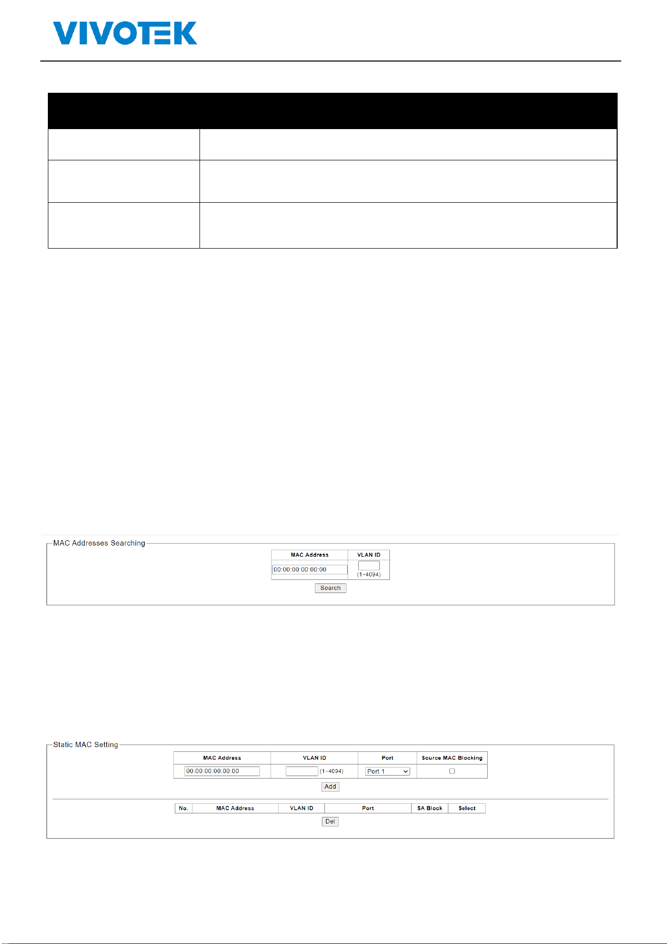
4.1. MAC Search
The switch supports MAC search
Click“ MAC Address”>” MAC Search”, shown as following:
Picture 4-1 MAC Search
4.2. Static MAC
The switch supports static MAC
Click“ MAC Address”>”Static MAC”,shown as following:
Picture 4-2 Static Static MAC
Lite Management PoE Switch Series User Guide
Description:
Parameters
Description
MAC Address
Select the port for configuration
VLAN ID
Enable and disable
Port
(0-4160)
Source MAC
Blocking
Click “Apply”for saving the changes
Click “Del” for saving the changes
5. PoE
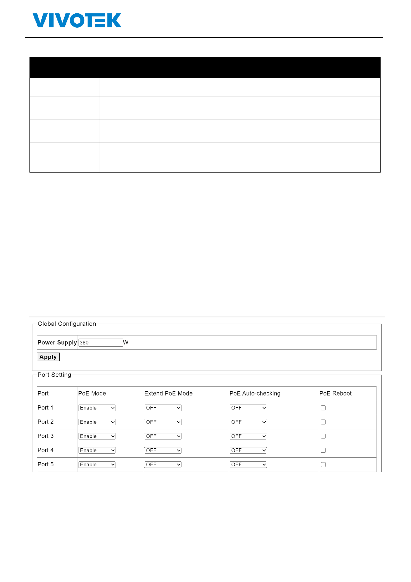
5.1. PoE Management
This page is used to configure the PoE function.
Click”PoE Management”>“PoE setting ”,shown as following:
Picture 5-1 Port Setting
Lite Management PoE Switch Series User Guide
Description:
Parameters
Description
Power supply
Configure the total power budge for PoE
PoE Mode
Enable/Disable the PoE function
PoE Reboot
Reboot the port PoE
Extend PoE Mode
Extend PoE power to 250M on this port
PoE Auto-checking
The PoE port will reboot PD when there is no traffic for 120 seconds.
PoE Reboot
Select to reboot the port’s PoE output
Click “Apply”for saving the changes
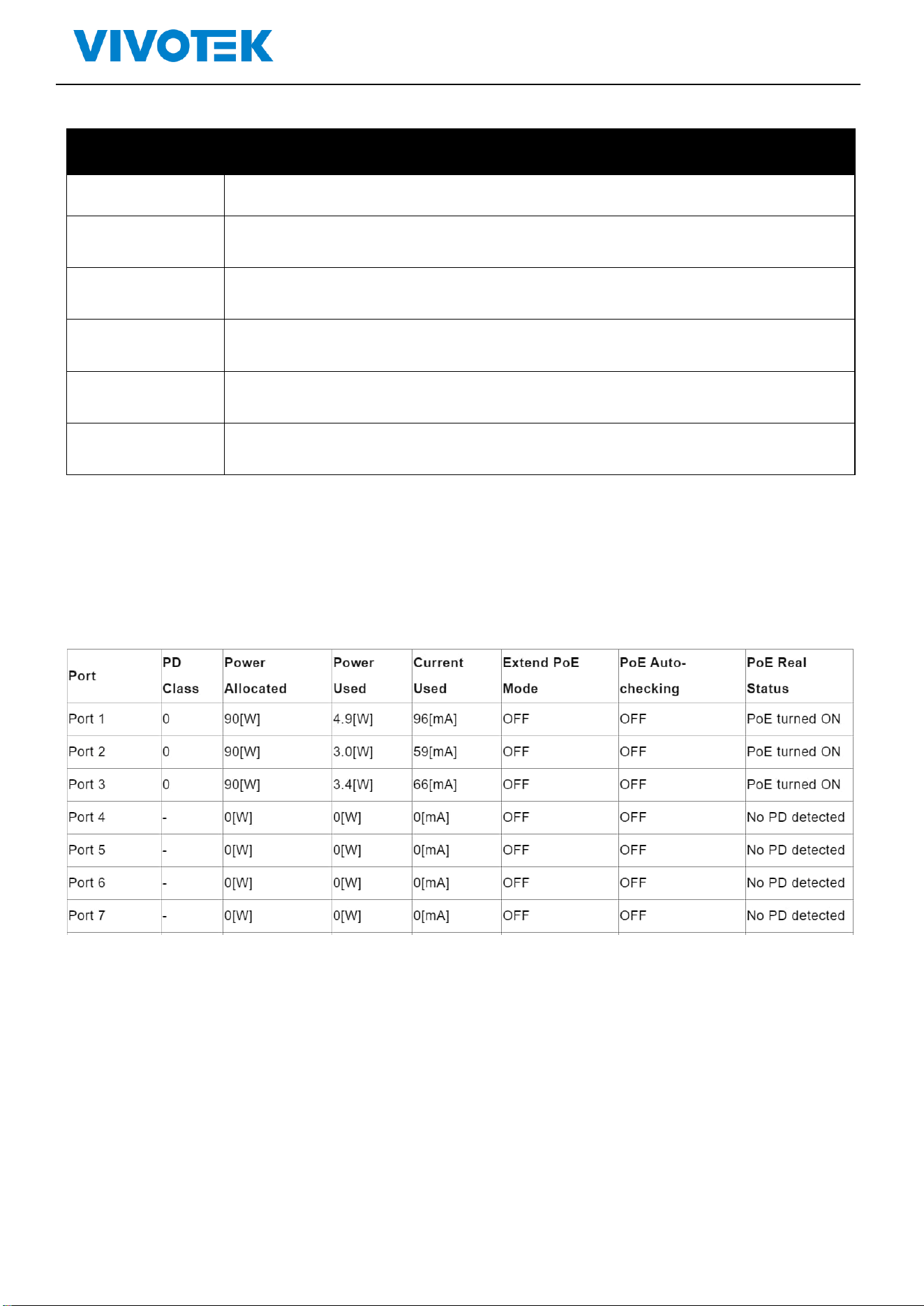
PoE Port status and information
It shows the status and detail information when you connect PoE devices to the PoE ports.
Lite Management PoE Switch Series User Guide
6. Port
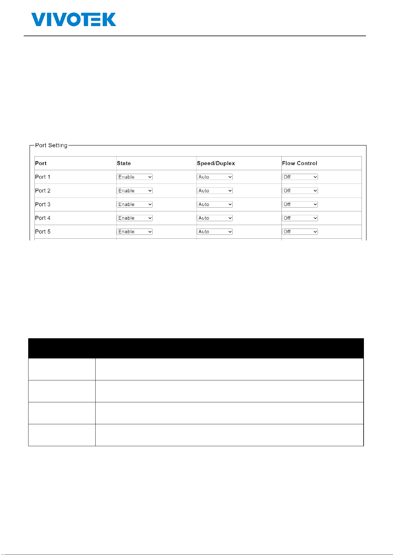
6.1. Port Management
Configure the port setting here
Click“Port”>“Port Setting”,shown as following:
Picture 6-1 Port Setting
Description:
Parameters
Description
Port
The port for configuration
State
Enable/Disable the port
Speed/Duplex
Choose the speed mode, can select Auto/ 10Mbps HDX/10Mbps FDX/ 100Mbps HDX
/100Mbps FDX/ 1000M FDX
Flow Control
Enable (on)/Disable(off) the flow control function
Click “Apply”for saving the changes
Lite Management PoE Switch Series User Guide
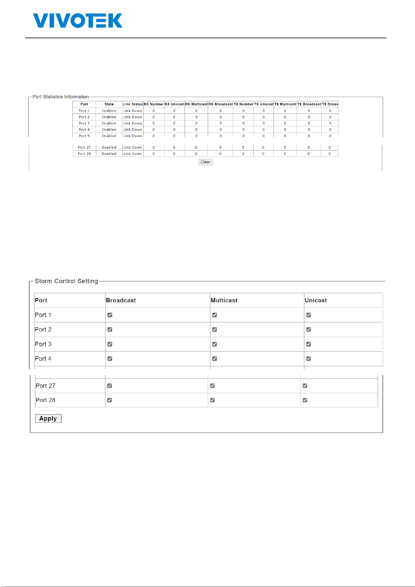
6.2. Port Statistics
Click“ Port”>“ Port Statistics”to check the configuration, shown as following:
Picture 6-2 Port Statistics
Click“clear”for saving the changes
6.3. Storm Control
The switch supports Storm Control
Click” Port ”>“ Storm Control”, shown as following:
Picture 6-3 Storm Control
Select the storm type for control, and click “Apply”for saving the changes
Lite Management PoE Switch Series User Guide
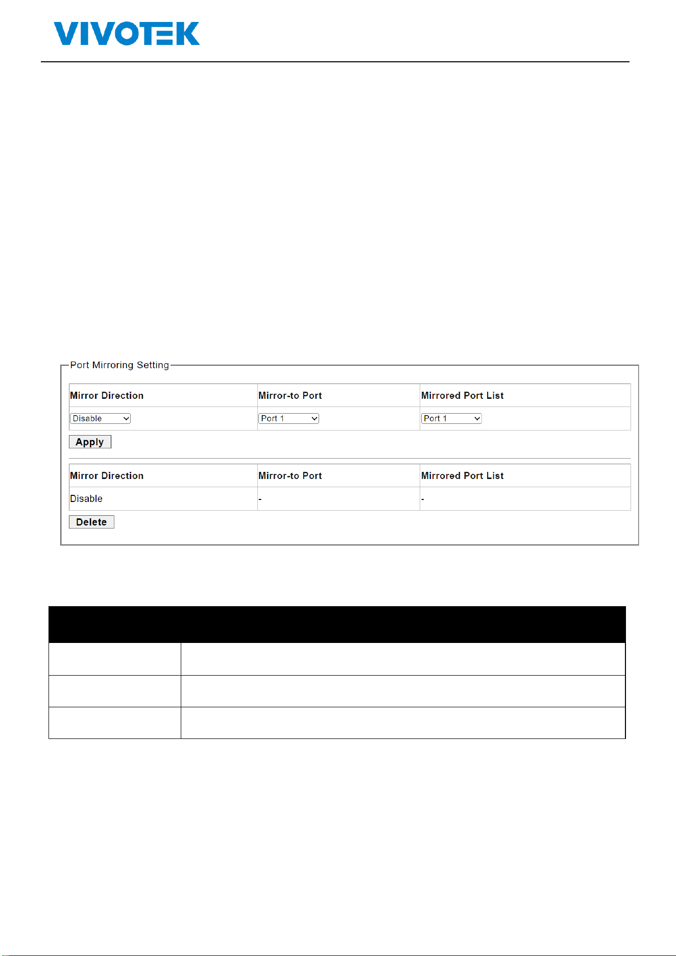
6.4. Port-based Mirroring
The port mirroring function completely maps the service or control packet traffic of some ports to
the specified port. The specified port is the “mirroring port", and the mapped port is the "mirrored
port". Connecting a network analyzer to a mirroring port can clearly analyze the packets of the
mirroring source port without destroying the normal services of the mirroring source port. Port
mirroring is a convenient online monitoring function. All ports of the system can be configured as
mirroring source ports, but only one mirroring destination port can be configured. When a port is
configured as a mirror port, its corresponding port cannot be configured as a source port. The source
port refers to the mirrored port, and multiple ports can be configured. The mirrored destination port
can only be configured with one port.
Click ”Port”>“ Port-based Mirroring”,shown as following:
Picture 6-4 Port S Mirroring
Description:
Parameters
Description
Mirroring Port
mirror destination port
Mirrored Port List
mirror source port
Mirror Direction
RX,TX,BOTH
Click “Apply”for saving the changes
6.5. Port Isolation
The switch supports port isolation function
Click”Port”>“ Port Isolation”, shown as following:
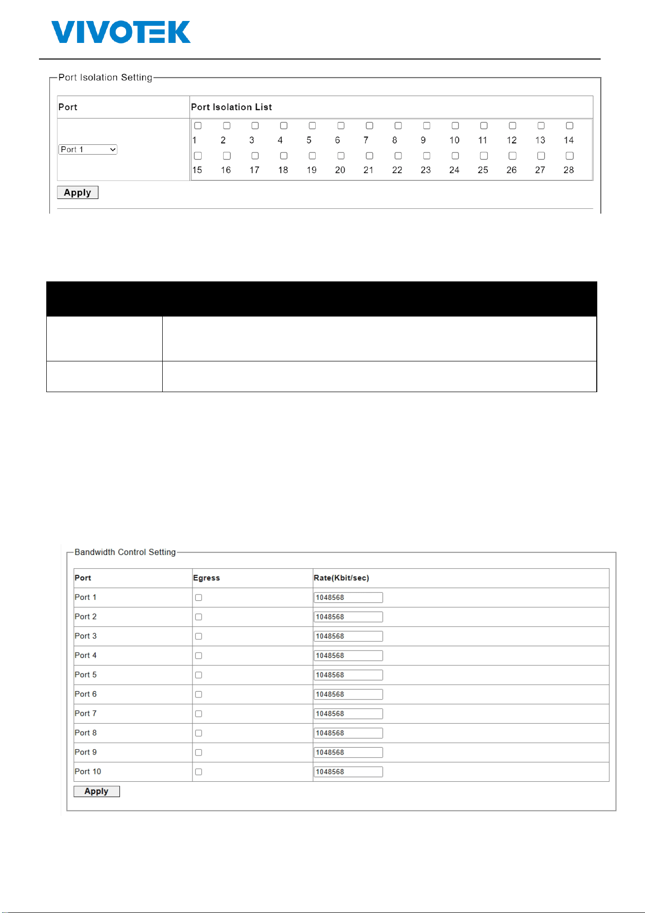
Lite Management PoE Switch Series User Guide
Picture 6-5 Port isolation
Description:
Parameters
Desription
Port
Select the port for configuration
Port Isolation List
Select the ports for isolation from the selected port
Click “Apply”for saving the changes
6.6. Bandwidth Control
The switch supports port bandwidth control configuration
Click ”Port”>“ Bandwidth Control”, shown as following:
Picture 6-6 Bandwidth Control
Description:
Lite Management PoE Switch Series User Guide
Parameters
Description
Port
The port for configuration
Egress
Click to enable/disable the Egress
Rate
Enter the packet rate (0-1000000, multiple of 8)
Click “Apply”for saving the changes
7. STP
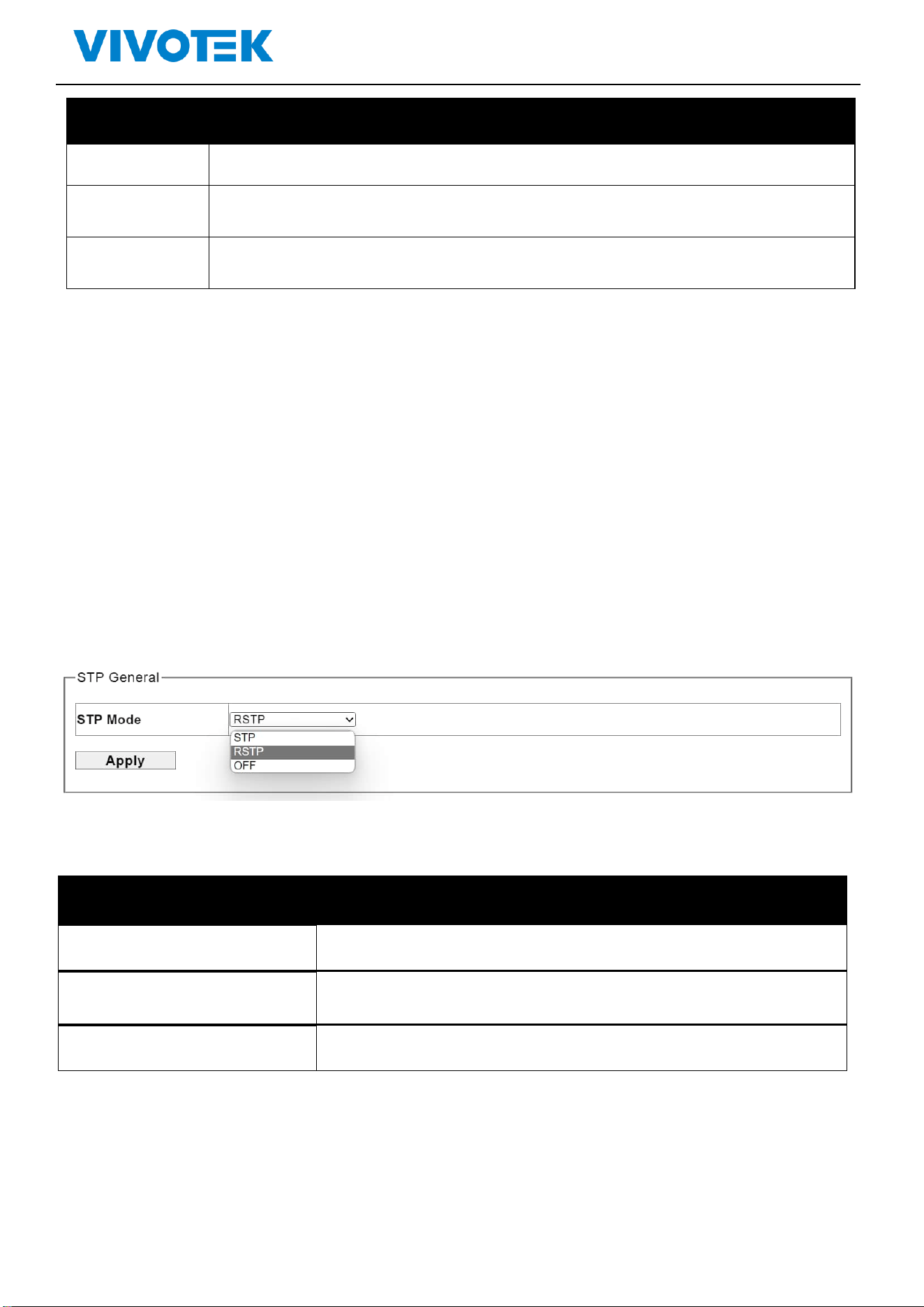
7.1. STP General
The user can configure spanning tree protocol to avoid looping and connect switches as ring topology
for cable redundancy.
Click”STP”>“STP General”, shown as following:
Picture 7.1 Spanning Tree Protocol
Description:
Parameters
Description
STP
Enable spanning tree protocol
RSTP
Enable rapid spanning tree protocol
OFF
Disable spanning tree protocol
Click “Apply”for saving the changes

Lite Management PoE Switch Series User Guide
7.2 STP Config
Picture 7.2 Spanning Tree Protocol Configuration
Description:
Parameters
Description
Priority
The priority parameter used in the CIST(Common and Internal
Spanning Tree) connection.
0 / 4096 / 8192 / 12288 / 16384 / 20480 / 24576 / 28672 / 32768 /
36864 / 40960 / 45056 / 49152 / 53248 / 57344 / 61440
Max.Age
6-40sec. The same definition as in the RSTP protocol.
Hello Time
By default, the hello time is 2 seconds. If the device does not receive
configuration BPDUs within the timeout period, it recalculates the
spanning tree. The formula for calculating the timeout period is
timeout period = timeout factor × 3 × hello time.
Forward Delay
4-30sec. The same definition as in the RSTP protocol.
Lite Management PoE Switch Series User Guide
8. QoS
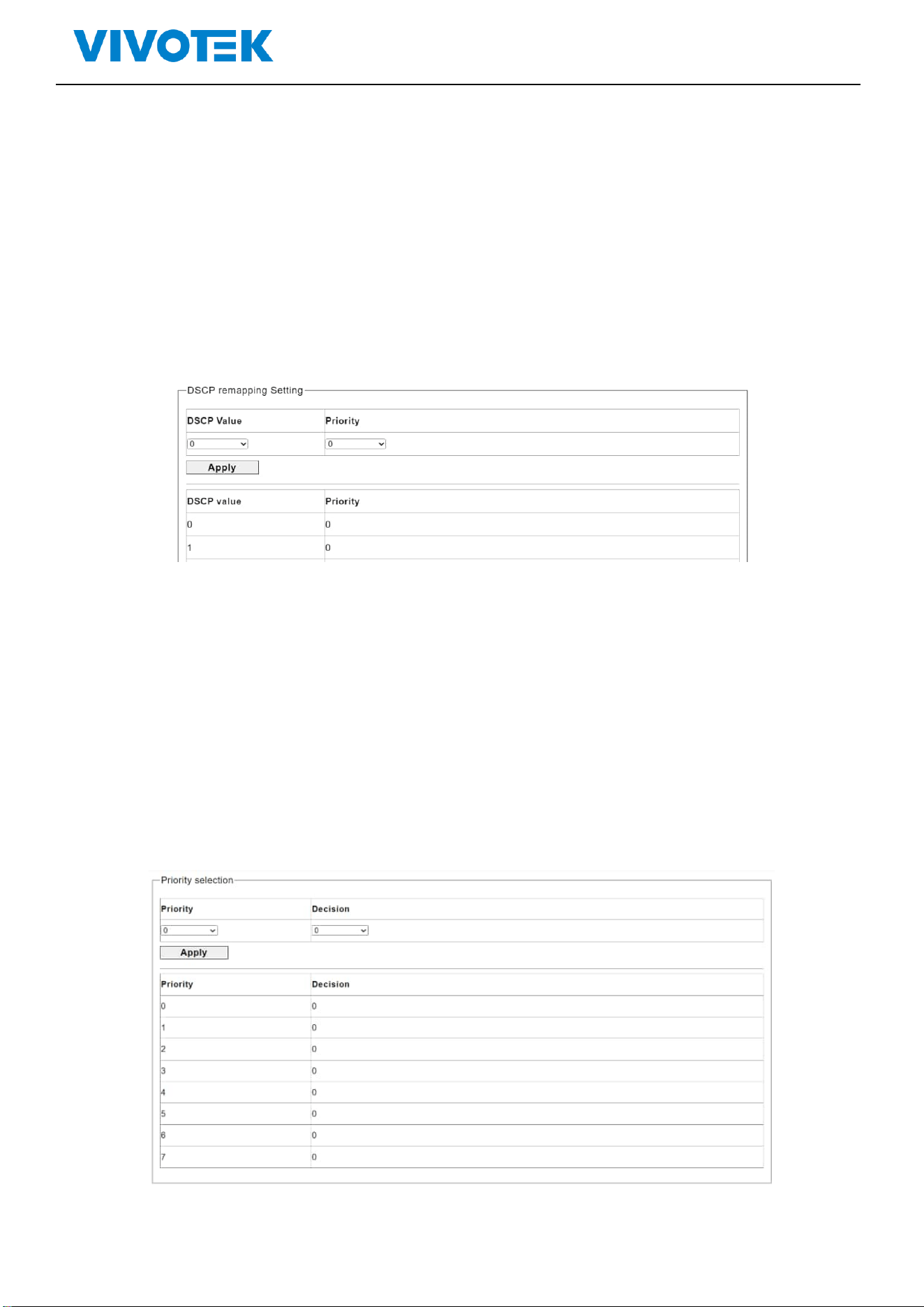
8.1. Dscp remapping
This page is used to configure port’s DSCP remapping.
Click “QoS”>“Dscp remapping”, shown as following:
Picture 7-1 Dscp remapping
Select the DSCP Value and priority in the pull-down list
Click “Apply”for saving the changes
8.2. Priority to Queue
Click“QoS”>“ Priority to Queue”, shown as following:
Picture 7-2 Priority to Queue
Lite Management PoE Switch Series User Guide
Select the Priority and Decision in the pull-down list
Click “Apply”for saving the changes
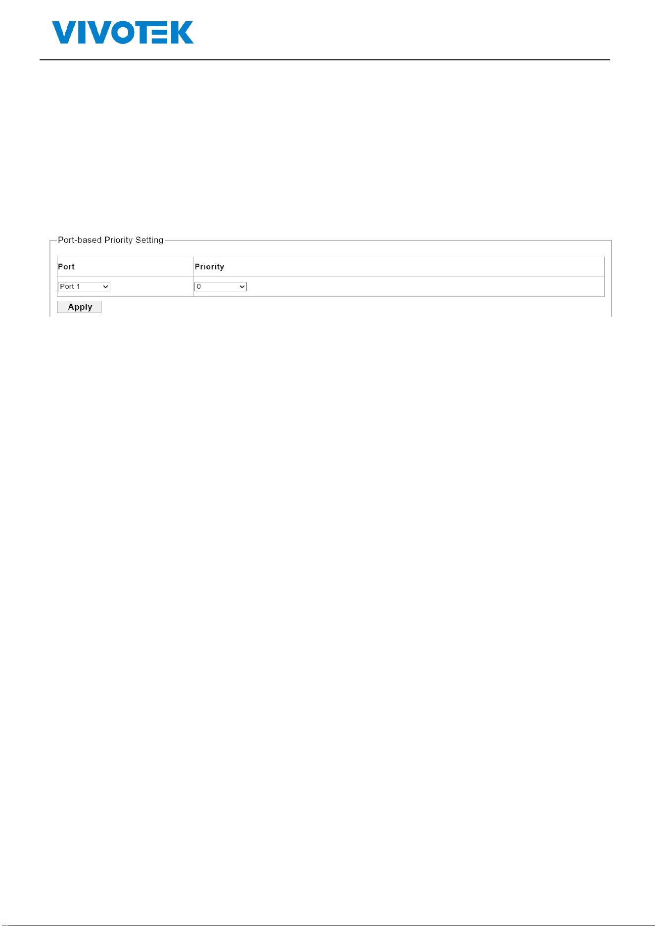
8.3. Port-based Priority
Click“QoS”>“ Port-based Priority ”, shown as following:
Picture 7-3 Port-based Priority
Select the port and priority in the pull-down list
Click “Apply”for saving the changes
Lite Management PoE Switch Series User Guide
9. Link Aggregation
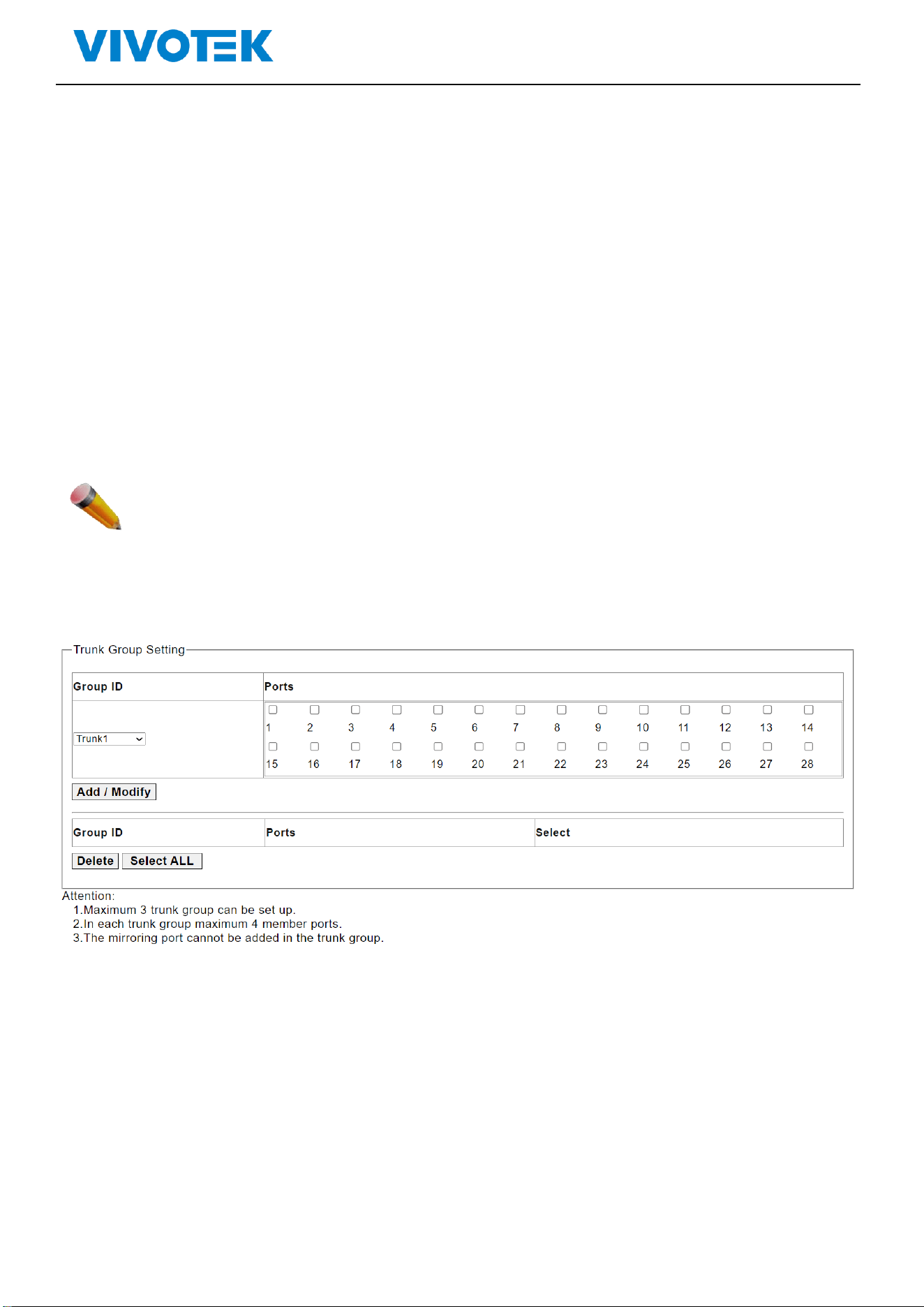
9.1. Trunk Group Setting
Users can establish multiple links between multiple switches. Link Aggregation is a method to increase
bandwidth by bundling a group of physical interfaces together as a logical interface. The switch series
supports up to 2-13 port aggregation groups in accordance with the port numbers.
Note: If any port in the link aggregation group is disconnected, packets sent to the disconnected port
will share the load with the other ports connected in the link aggregation group.
On this page, the user can configure the port static aggregation settings of the switch.
Click ”Link Aggregation”>“Trunk Group Setting”, shown as following:
Picture 8-1 Trunk Group Setting
Configuration Description:
Lite Management PoE Switch Series User Guide
Parameters
Description
Group ID
Trunk group ID, maximum 3 trunk groups
Ports
Ports numbers in a trunk group
Click “Apply”for saving the changes
Click Delete to delete the selected trunk group
Note: A static trunk group can be configured with up to 4 ports.
10. Maintenance
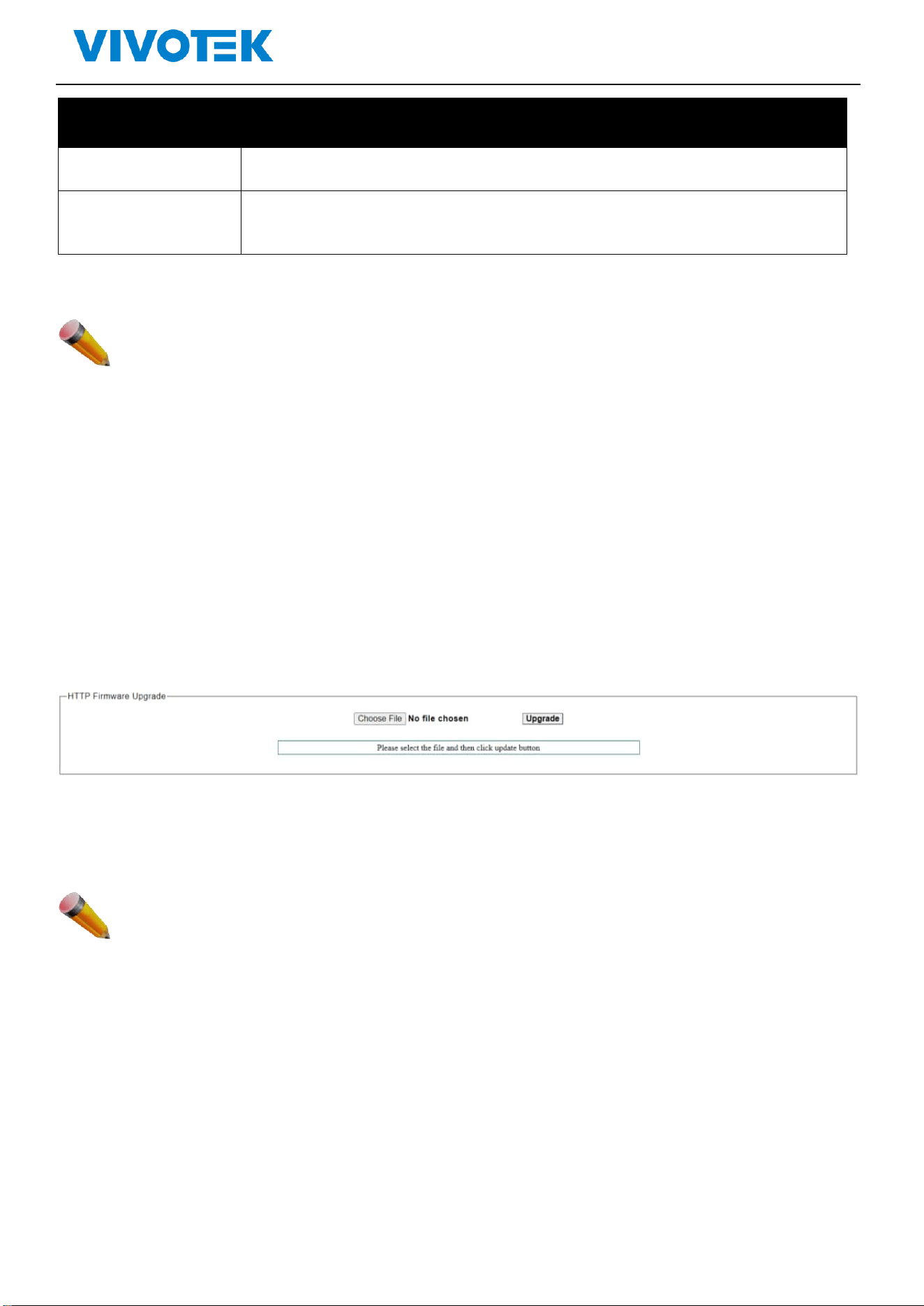
10.1. Firmware Upgrade
The switch supports firmware upgrade on-line
Click“Tools” > “ Firmware Upgrade“,shown as following:
Picture 9-1 Firmware Upgrade
Click “choose file” to upload a new firmware file, then click “upgrade” to update to the new
version firmware
Note: After upgrading, the switch will reboot automatically and back to the log in page
:
Lite Management PoE Switch Series User Guide
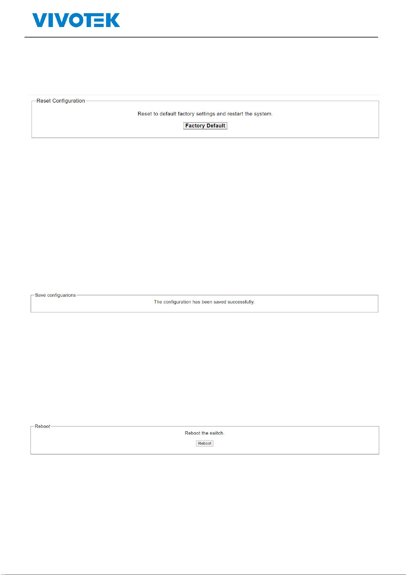
10.2. Reset
Click“Tools” > “Reset“, shown as following:
Picture 9-3 factory default
Click factory default to restore
10.3. Save
Click“Maintenance” > “Save“ to save configuration, shown as following:
*Please note that you must save configuration after you change the settings otherwise the settings
that you change will be gone after switch rebooting.
Picture 9-4 Save
10.4. Reboot
Click“Maintenance” > “reboot“, to reboot the switch, shown as following:
Picture 9-5 Reboot