Users Guide & Installation
Handbook
Stoves
Built-in Gas
Part No 083137104 Date 25/09/2017

CONTENTS & INTRODUCTION
3.000
CONTENTS
• SAFETY
• USING THE PRODUCT
• CLEANING
• INSTALLATION INSTRUCTIONS
• TECHNICAL DATA
• CUSTOMER CARE
INTRODUCTION
Thank you for buying this
British-built appliance from us.
This guide book is designed to help you
through each step of owning your new
cooker, from installation to use. Please
read it carefully before you start using
your product, as we have endeavored to
answer as many questions as possible,
and provide you with as much support
as we can.
If,however,youshouldndsomething
missing, or not covered, please contact
our Customer Care team. Their number is
located on the back page of this book.
For customers outside the UK and
Northern Ireland, please contact your
local supplier.
When you dial this number you will hear
a recorded message and be given a
number of options. This indicates that
your call has been accepted and is
being held in a queue. Calls are answered
in strict rotation as our Customer Care
representatives become available.
Alternatively, general information, spares
and service information is available from
our website. The address is located on the
back page of this book.
WARRANTY
Your new appliance comes with our
12-month guarantee, protecting you
against electrical and mechanical
breakdown. To register your appliance
please call 0844 481 0182, complete
the registration form included or register
online at the web address located on the
back page of this book.
For full terms & conditions of the manu-
facturer’s guarantee, refer to the website
on the back of this book.
In addition, you may wish to purchase
anextendedwarranty.Aleaet
explaining how to do this is included
with your appliance.
European Directives
As a producer and a supplier of
cooking appliances we are
committed to the protection of
the environment and are in the
compliance with the WEEE directive. All
our electric products are labelled accord-
ingly with the crossed out wheeled bin
symbol. This indicates, for disposal
purposes at end of life, that these
products must be taken to a recognised
collection points, such as local authority
sites/local recycling centres.
This appliance Complies with European
Community Directives (CE) for household
and similar electrical appliances and Gas
appliances where applicable.
This appliance conforms to European Di-
rective 2009/125/EC regarding Eco design
requirements for energy-related products.

CONTENTS & INTRODUCTION
3.000
Our policy is one of constant
development and improvement,
therefore we cannot guarantee the strict
accuracy of all of our illustrations and
specications-changesmayhavebeen
made subsequent to publishing.
GAS WARNING
If you smell gas:
Do not try to light any appliance.
Do not touch any electrical switch.
Call the Gas Emergency Helpline at
0800 111999

WARNING
• Duringusetheappliancebecomeshot.Careshouldbetakento
avoidtouchingheatingelements.
• Theapplianceanditsaccessiblepartsbecomehotduringuse.
Careshouldbetakentoavoidtouchingheatingelements.Children
lessthan8yearsofageshallbekeptawayunlesscontinuously
supervised.Thisappliancecanbeusedbychildrenagedfrom8
yearsandaboveandpersonswithreducedphysicalsensoryor
mentalcapabilitiesorlackofexperienceandknowledgeifthey
havebeengivensupervisionorinstructionconcerningtheuseof
theapplianceinasafewayandunderstandthehazardsinvolved.
Childrenshallnotplaywiththeappliance.Cleaninganduser
maintenanceshallnotbemadebychildrenwithoutsupervision.
• Donotuseharshabrasivecleanersorsharpmetalscrapersto
cleantheovendoorglasssincetheycanscratchthesurface,
whichmayresultinshatteringoftheglass.
• Donotuseasteamcleaneronanycookingrange,hobsandoven
appliances.
• Ensurethattheapplianceisswitchedoffbeforereplacingthelamp
toavoidelectricshock.
• Accessiblepartsmaybecomehotwhenthegrillisinuse.Children
shouldbekeptaway.
CAUTION
• Theuseofagascookingapplianceresultsintheproductionof
heat,moistureandproductsofcombustionintheroominwhich
itisinstalled.Ensurethatthekitcheniswellventilatedespecially
whentheapplianceisinuse:keepnaturalventilationholesopen
orinstallamechanicalventilationdevice(mechanicalextractor
hood).Prolongedintensiveuseoftheappliancemaycallfor
additionalventilation,forexampleopeningofawindow,ormore
effectiveventilation,forexampleincreasingthelevelofmechanical
ventilationwherepresent.
• Thisapplianceisforcookingpurposesonly.Itmustnotbeusedfor
otherpurposes,forexampleroomheating.
SAFETY

• Thisappliancemustnotbeinstalledbehindadecorativedoorin
ordertoavoidoverheating.
• FireSafetyAdvice
Ifyoudohaveareinthekitchen,don’ttakeanyrisks-geteveryoneoutofyourhomeandcallthe
FireBrigade.
Ifyouhaveanelectricalreinthekitchen:
• Pulltheplugout,orswitchoffthepoweratthefusebox-thismaybeenoughtostopthereimme-
diately
• Smothertherewithareblanket,oruseadrypowderorcarbondioxideextinguisher
• Remember:neverusewateronanelectricalorcookingoilre.
• OtherSafetyAdvice
• Servicingshouldbecarriedoutonlybyauthorisedpersonnel.
• Donotoperatetheappliancewithouttheglasspanelcorrectlytted.
• Thereisariskofelectricshock,soalwaysmakesureyouhaveturnedoffandunpluggedyour
appliancebeforestarting.Alwaysallowtheproducttocooldownbeforeyouchangeabulb.
• Donotmodifytheouterpanelsofthisapplianceinanyway.
• Thisappliancemustbeearthed.
• Theappliancemustneverbedisconnectedfromthemainssupplyduringuse,asthiswillseriously
affectthesafetyandperformance,particularlyinrelationtosurfacetemperaturesbecominghotand
gasoperatedpartsnotworkingefciently.Thecoolingfan(iftted)isdesignedtorunonafterthe
controlknobhasbeenswitchedoff.
• GASWARNING!-Ifyousmellgas:Donottrytolightanyappliance,Donottouchanyelectrical
switch.Contactyourlocalgassupplierimmediately.

USING THE GRILL - ELECTRIC (IF FITTED)
7.130
Caution: Accessible parts may be
hot when the grill is used - young
children should be kept away.
A grill pan handle can be purchased as an
optional extra from our spares department
quoting the numbers below.
Handle - 082283705
Handle grip - 082469100
Complete grillpan pack - 012635666
Contact details can be found on the
customer care page.
If cleaning the grill pan when it is hot, use
oven gloves to move it.
Food for grilling should be positioned
centrally on the trivet.
Using the grill
Important: The grill door must be fully
open when the grill is used.
Open the grill door. Turn the grill control
knob to the grill symbol position. For
best cooking results, we recommend that
you preheat the grill for about 3 minutes.
Push the grill pan towards the back of the
shelf, to position it under the grill.
The speed of grilling can be controlled by
selecting a higher or lower shelf position.
For toasting, and for grilling foods such as
bacon, sausages or steaks, use a higher
shelf position. For thicker foods such
as chops or chicken joint pieces, use a
middle to low shelf position.
The grill trivet, inside the grill pan, can
be inverted to give a high or low position,
or it may be removed. The HIGH trivet
position is suitable for toasting bread. The
LOW trivet position is suitable for grilling
alltypesofmeat&sh.
With the grill trivet removed the food is
placed directly on the base of the grill pan
-eg:whencookingwholeshorbrowning
dishessuchascauliowercheese.
To switch off, turn the control knob to the
off position.
Aluminium foil
Using aluminium foil to cover the grill pan,
or putting items wrapped in foil under the
grillcreatesarehazard.
The cooling fan (if tted)
When the grill is switched on, after a short
delay, the cooling fan comes on to keep
the fascia and control knobs cool during
grilling. The fan may continue to oper-
ate for a period after the grill has been
switched off.
During use the fan may cycle on and off,
this is normal.

USING THE TOP OVEN - GAS (IF FITTED)
USING THE TOP OVEN
Ignition
Push in and turn the top oven control
knob to the ‘FULL ON’ position. Hold the
control knob in, and press the ignition
switch(iftted)orholdalightedmatch
or taper to the burner, until the burner
lights. Hold the control knob in for 15
seconds. Do not hold the control knob in
for longer that 15 seconds. If the burner
fails to light within this time, release the
control knob and wait one minute before
attempting further ignition.
Turn the control knob to the required
setting.
To switch off, return the control knob to
the off position.
Note; Some appliance’s are automatic ig-
nition and do not have an ignition switch.
Using the top oven
The top oven can be used in the same
way as the main oven, to cook the full
range of dishes, but it is a SECONDARY
oven and there are some differences.
Foods cooked in the top oven should be
inrelationtotheovensize.Largerdishes,
or food which may rise during cooking,
should be cooked in the main oven.
Large items, wide tins and tall items such
as rich fruit cakes should be cooked in the
main oven to obtain optimum results.
Notes:
As part of the cooking process, hot air is
expelled through a vent at the top of the
oven(s). When opening the oven door,
care should be taken to avoid any possible
contact with potentially hot air, since this
may cause discomfort to people with sen-
sitive skin. We recommend that you hold
the underneath of the oven door handle.
Preheating
Always preheat the top oven for 15 min-
utes. However, if the main oven is being
used at the same time, then preheating
may not be necessary. The cooking time
may need to be shortened slightly, or the
cooking temperature adjusted, to allow
for heat transfer from the main oven
to the top oven if both ovens are used
together.
If you are not preheating the oven, the
cooking times in the baking guide may
need to be extended, as they are based
on a preheated oven.
The oven must be preheated when
reheatingfrozenorchilledfoods,and
we recommend preheating for yeast
mixtures,batters,soufésandwhisked
sponges.
Put the oven shelves in the position re-
quired before preheating the oven.
Zones of heat
The temperature at the centre of the oven
corresponds with the selected gas mark
and is slightly higher towards the top of
the oven and slightly lower towards the
oven base.
Thesezonesofheatcanbeusefulasdif-
ferent dishes requiring different tempera-
tures can be cooked at the same time,
when more than one shelf is used.
The temperature at the oven base is suit-
able for cooking baked vegetables, baked
fruit, milk pudding etc, and for warming
bread rolls, soup, coffee, or ovenproof
plates and dishes.
Ifyoundthatoveraperiodoftime,
the oven becomes hotter when used at a
particular gas mark, the thermostat may
need to be replaced.

USING THE TOP OVEN - GAS (IF FITTED)
OVEN FURNITURE
Baking tray and roasting tins
For best cooked results and even brown-
ing,themaximumsizebakingtraysand
roasting tins that should be used are as
follows;
Baking tray 350mm x 330mm
Roasting tin 370mm x 320mm
Position baking trays and roasting tins on
the middle of the shelves, and leave one
clear shelf position between shelves, to
allow for circulation of heat.
Oven shelves
Extra shelves may be ordered from your
local supplier.
The oven shelf must be positioned with
the upstand at the rear of the oven and
facing upwards.
The top oven shelf helps to ensure even
baking in the top oven. It has a rear de-
ectorttedtoit,andisnot intended for
use in the main oven.
OVEN LIGHT (IF FITTED)
Press the light button on the facia panel.
If there is no light button the oven light
will come on when the oven control is
operated.
SLOW COOKING
Makesurethatfrozenfoodsarethorough-
ly thawed before cooking.
Do not slow cook joints of meat or poultry
weighing more than 2¼kg / 4½lb.
Always use the top half of the oven for
slow cooking.
For roasting joints of meat or poultry, and
for pot roasts preheat the oven to gas
mark 6 and cook for 30 minutes, then
adjust the oven control to the “S” slow
setting for the remainder of the cooking
time.
Slow cooking times will be about three
times as long as conventional cooking
times.

USING THE TOP OVEN - GAS (IF FITTED)
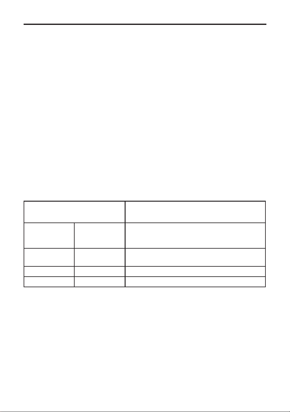
Dish Recommended
gas mark
Suggested
shelf
position
Approximate
cooking time
(preheated
oven)
Scones
Meringues
7
“S” slow setting
top - middle
bottom
10 - 15 mins
2 - 3 hours
Cakes
Small cakes
Whisked sponge
Swiss roll
Victoria sandwich
(2 x 180mm / 7” per shelf)
Genoese Sponge
(2 x 180mm / 7” per shelf)
5
5
6
4
5
middle
middle
middle
middle
(side by side)
middle
15 - 25 mins
20 - 30 mins
10 - 12 mins
20 - 35 mins
25 - 30 mins
Pastry
Rough Puff
Flaky / Puff
Shortcrust
Flan
7
6
6
6
middle
middle
middle
middle
cooking time
depends on
recipe & type
oflling
Biscuits
Shortbreadngers
Nut brownies
Brandy snaps
Flapjacks
Ginger nuts
5
5
4
4
5
middle - top
middle
middle - top
middle - top
middle - top
TOP OVEN BAKING GUIDE
Baking guide hints
The gas mark settings and times given
in the top baking guides are based on
dishes made wit block margarine. If tub
margarine is used, it may be necessary to
reduce the gas mark setting.
If a different gas mark setting to that
shown in our guide is given in a recipe,
the recipe instruction should be followed.
The cooking times given in the baking
guides are based on a preheated oven.
If you do not preheat the oven, cooking
times should be extended.

USING THE TOP OVEN - GAS (IF FITTED)
Traditional fruit cakes
It should be remembered that ovens can
vary over time, therefore cooking times
canvary,makingitdifculttobeprecise
when baking fruit cakes.
It is necessary therefore, to test the cake
beforeremovalfromtheoven.Useane
warmed skewer inserted into the centre of
the cake. If the skewer comes out clean,
then the cake is cooked.
• Do not attempt to make Christmas
cakes larger than the oven can cope
with, you should allow at least 25mm
(1 inch) space between the oven
walls and the tin.
• Always follow the temperatures rec-
ommended in the recipe.
• To protect a very rich fruit cake dur-
ing cooking, tie 2 layers of brown
paper around the tin.
• We recommend that the cake tin is
not stood on layers of brown paper,
as this can hinder effective circulation
of air.
• Do not use soft tub margarine for
richfruitcakes,unlessspeciedin
the recipe.
• Alwaysusethecorrectsizeand
shape of tin for the recipe quantities.
Roast turkey
Roasting turkey involves cooking two
different types of meat - the delicate light
breast meat, which must not be allowed
to dry out, and the darker leg meat,
which takes longer to cook.
The turkey must be roasted long enough
for the legs to cook, so frequent bast-
ing is necessary. The breast meat can be
covered once browned.
• Always make sure that the turkey is
completely thawed and that the gib-
lets are removed before cooking.
• Turkey should be roasted at gas
mark 5 for 20 minutes per lb, plus 20
minutes, unless packaging advises
otherwise.
• The turkey can be open roasted,
breast side down, for half of the cook
time, and then turned over for the
remainder of the cooking time.
• If the turkey is stuffed, add 5 minutes
per lb to the cooking time.
• If roasting turkey covered with foil,
add 5 minutes per 1lb to the cooking
time.
To test if the turkey is cooked, push a
neskewerintothethickestpartofthe
thigh. If the juices run clear, the turkey
is cooked. If the juices are still pink, the
turkey will need longer cooking.
Please note:- for all other Roasting guides refer to main oven section and
see table.
USING THE TOP OVEN - GAS (IF FITTED)
Cook in oven at Gas Mark 5 Approximate Cooking Time
(preheated oven)
Beef Rare
Medium
Well done
20 minutes per 450g (1lb), plus 20 minutes
25 minutes per 450g (1lb), plus 25 minutes
30 minutes per 450g (1lb), plus 30 minutes
Lamb Medium
Well Done
25 minutes per 450g (1lb), plus 25 minutes
30 minutes per 450g (1lb), plus 30 minutes
Pork 35 minutes per 450g (1lb), plus 35 minutes
Poultry 20 minutes per 450g (1lb), plus 20 minutes
Roasting guide
The times given in the roasting guide
areonlyapproximate,becausethesize
andageofthebirdwillinuencecooking
times as will the shape of a joint and the
proportion of the bone.
Frozenmeatshouldbethoroughlythawed
before cooking. For large joints it is advis-
able to thaw overnight.
Frozenpoultryshouldbethoroughly
thawed before cooking. The time required
dependsonthesizeofthebird-eg;a
large turkey may take up to 48 hours to
thaw.
Use of a trivet with a roasting tin will
reduce fat splashing and will help to keep
the oven interior clean. Alternatively, to
help reduce fat splashing, potatoes or
other vegetables can be roasted around
the meat/poultry.
Notes:
• When cooking stuffed meat or poultry
calculate the cooking time from the
total weight of the meat plus the
stufng.
• For joints cooked in foil or covered
roasters, and for lidded casseroles,
add 5 minutes per 450g (1lb) to the
calculated cooking time.
• Smaller joints weighing less than
1.25kg (2½lb) may require 5 minutes
per 450g (1lb) extra cooking time.
• Position the oven shelf so that the
meat or poultry is in the centre of the
oven.
• It is recommended that the appliance
is cleaned after open roasting.

USING THE MAIN OVEN - GAS
USING THE MAIN OVEN
Ignition
Push in and turn the main oven control
knob to the ‘FULL ON’ position. Hold the
control knob in, and press the ignition
switch(iftted)orholdalightedmatch
or taper to the burner, until the burner
lights. If after 15 seconds, the burner has
not lit, turn off the oven and leave the
compartment door open. Wait at least one
minute before a further attempt to ignite
the burner.
Do not hold the control knob in for more
than 15 seconds.
Turn the control knob to the required
setting.
Note; Some appliance’s are automatic
ignition and do not include neither require
an ignition switch.
To turn off, return the control knob to the
“off” position.
Preheat the main oven for 15 minutes.
If you are not preheating the oven, the
cooking times in the baking guides may
need to be extended, as they are based
on a preheated oven.
The oven must be preheated when
reheatingfrozenorchilledfoods,and
we recommend preheating for yeast
mixtures,batters,soufésandwhisked
sponges. Put the oven shelves in the posi-
tion required before preheating the oven.
Zones of heat
The temperature at the centre of the oven
corresponds with the selected gas mark
and is slightly higher towards the top of
the oven and slightly lower towards the
ovenbase.Thesezonesofheatcanbe
useful as different dishes requiring differ-
ent temperatures can be cooked at the
same time, when more than one shelf is
used.
The temperature at the oven base is suit-
able for cooking baked vegetables, baked
fruit, milk pudding etc, and for warming
bread rolls, soup, coffee, or ovenproof
plates and dishes.
Ifyoundthatoveraperiodoftime,
the oven becomes hotter when used at a
particular gas mark, the thermostat may
need to be replaced.
Oven light (if tted)
Press the light button on the facia panel.
If there is no light button the oven light
will come on when the oven control is
operated.
OVEN FURNITURE
Baking tray and roasting tins
For best cooked results and even brown-
ing,themaximumsizebakingtraysand
roasting tins that should be used are as
follows;
Baking tray 350mm x 330mm
Roasting tin 370mm x 320mm
Position baking trays and roasting tins on
the middle of the shelves, and leave one
clear shelf position between shelves, to
allow for circulation of heat.
Oven shelves
Extra shelves may be ordered from your
local supplier.
The oven shelf must be positioned with
the up-stand at the rear of the oven and
facing upwards.
SLOW COOKING
Makesurethatfrozenfoodsarethorough-
ly thawed before cooking.
Do not slow cook joints of meat or poultry
weighing more than 2¼kg/4½lb.
Always use the top half of the oven for
slow cooking.

USING THE MAIN OVEN - GAS
For roasting joints of meat or poultry, and
for pot roasts preheat the oven to gas
mark 6 and cook for 30 minutes, then
adjust the oven control to the “S” slow
setting for the remainder of the cooking
time.
Slow cooking times will be about three
times as long as conventional cooking
times.
MAIN OVEN BAKING GUIDE
Dish Recom-
mended gas
mark
Suggested
shelf position
Approximate
cooking time
(preheated
oven)
Scones
Meringues
7
“S” slow set
middle - top
bottom
8 - 15 mins
2 - 3 hours
Cakes
Small cakes
Whisked sponge
Swiss roll
Victoria sandwich
(2 x 180mm/7”)
Genoese sponge
Madeira (180mm/7”)
Gingerbread
Semi rich fruit cake
(205mm/8”)
Christmas cake
(205mm/8”)
Dundee cake (205mm/8”)
5
5
6
4
4
3
3
2 or 3
1 or 2
3
middle - top
middle - top
middle - top
middle - top
middle
middle
middle
middle - top
bottom
middle - bottom
15 - 25 mins
20 - 25 mins
10 - 12 mins
20 - 30 mins
20 - 30 mins
1 - 1¼ hours
1 - 1¼ hours
2½ - 3 hours
depending on
recipe
2 - 2½ hours
Pastry
Rough Puff
Flaky/Puff
Shortcrust
Flan
7
6
6
6
middle - top
middle - top
middle - top
middle - top
Cooking time
depends on
recipe and type
oflling
Biscuits
Nut brownies
Brandy snaps
Flapjacks
Gingernuts
5
4
4
4
middle - top
middle - top
middle - top
middle - top
25 - 35 mins
10 - 12 mins
20 - 25 mins
10 - 20 mins

USING THE MAIN OVEN - GAS
Traditional fruit cakes
It should be remembered that ovens can
vary over time, therefore cooking times
canvary,makingitdifculttobeprecise
when baking fruit cakes.
It is necessary therefore, to test the cake
beforeremovalfromtheoven.Useane
warmed skewer inserted into the centre of
the cake. If the skewer comes out clean,
then the cake is cooked.
• Do not attempt to make Christmas
cakes larger than the oven can cope
with, you should allow at least 25mm
(1 inch) space between the oven
walls and the tin.
• Always follow the temperatures rec-
ommended in the recipe.
• To protect a very rich fruit cake dur-
ing cooking, tie 2 layers of brown
paper around the tin.
• We recommend that the cake tin is
not stood on layers of brown paper,
as this can hinder effective circulation
of air.
• Do not use soft tub margarine for
richfruitcakes,unlessspeciedin
the recipe.
• Alwaysusethecorrectsizeand
shape of tin for the recipe quantities.
Roast turkey
Roasting turkey involves cooking two
different types of meat - the delicate light
breast meat, which must not be allowed
to dry out, and the darker leg meat,
which takes longer to cook.
The turkey must be roasted long enough
for the legs to cook, so frequent bast-
ing is necessary. The breast meat can be
covered once browned.
• Always make sure that the turkey is
completely thawed and that the gib-
lets are removed before cooking.
• Turkey should be roasted at gas
mark 5 for 20 minutes per lb, plus 20
minutes, unless packaging advises
otherwise.
• The turkey can be open roasted,
breast side down, for half of the cook
time, and then turned over for the
remainder of the cooking time.
• If the turkey is stuffed, add 5 minutes
per lb to the cooking time.
• If roasting turkey covered with foil,
add 5 minutes per 1lb to the cooking
time.
To test if the turkey is cooked, push a
neskewerintothethickestpartofthe
thigh. If the juices run clear, the turkey
is cooked. If the juices are still pink, the
turkey will need longer cooking.
USING THE MAIN OVEN - GAS
Roasting guide
The times given in the roasting guide
areonlyapproximate,becausethesize
andageofthebirdwillinuencecooking
times as will the shape of a joint and the
proportion of the bone.
Frozenmeatshouldbethoroughlythawed
before cooking. For large joints it is advis-
able to thaw over night.
Frozenpoultryshouldbethoroughly
thawed before cooking. The time required
dependsonthesizeofthebird-eg;a
large turkey may take up to 48 hours to
thaw.
Use of a trivet with a roasting tin will
reduce fat splashing and will help to keep
the oven interior clean. Alternatively, to
help reduce fat splashing, potatoes or
other vegetables can be roasted around
the meat/poultry.
Cook in oven at Gas Mark 5 Approximate Cooking Time
(pre-heated oven)
Beef Rare
Medium
Well done
20 minutes per 450g (1lb), plus 20 minutes
25 minutes per 450g (1lb), plus 25 minutes
30 minutes per 450g (1lb), plus 30 minutes
Lamb Medium
Well Done
25 minutes per 450g (1lb), plus 25 minutes
30 minutes per 450g (1lb), plus 30 minutes
Pork 35 minutes per 450g (1lb), plus 35 minutes
Poultry 20 minutes per 450g (1lb), plus 20 minutes
Notes:
• When cooking stuffed meat or poultry
calculate the cooking time from the
total weight of the meat plus the
stufng.
• For joints cooked in foil or covered
roasters, and for lidded casseroles,
add 5 minutes per 450g (1lb) to the
calculated cooking time.
• Smaller joints weighing less than
1.25kg (2½lb) may require 5 minutes
per 450g (1lb) extra cooking time.
• Position the oven shelf so that the
meat or poultry is in the centre of the
oven.
• It is recommended that the appliance
is cleaned after open roasting.
Press and hold the (plus) button and
P1willash.Pressthe (plus) button
oncethenP2willash.Thenpressthe
function button once
To select an alarm tone
Press and hold the button (minus)
buttontolistentorsttone.Releasethe
button and press it again to listen to the
second tone, etc. Releasing the button
after the tone has sounded will automati-
cally select that tone.
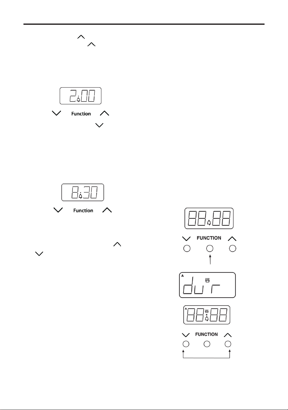
Setting the minute minder
Press and release the function button.
The minute minder bell symbol will appear
andashonthedisplay.Usethe plus
and minus buttons to set the required
alarm time. After setting, the display will
revert to show the time of day and the
bellsymbolwillstopashing.Pressingthe
function button will display the minutes
remaining. If the time has counted down
to the last minute, the remaining seconds
are shown. The tone will sound at the end
of the time set. To cancel the tone, press
the function button.
SEMI-AUTOMATIC COOKING
The duration method
• Press the function button twice,(1)
which will skip past the Minute
Minder.
• TheLEDdisplaywillashtheword
‘dur’,(2)andthe‘A’willashonthe
left hand side of the display.
• Use the Plus and Minus buttons to set
the length of time you want to cook
for(3). This must be done within 5
seconds or the time of day will show
again.
Once this is done the oven will automati-
cally switch off once the time has elapsed,
and the alarm will sound.
To switch off the alarm, press any button.
To view any remaining time press the
function button twice.
1.
2.
3.
USING THE CLOCK/PROGRAMMER - GAS

CLEANING
12.000
General
• It is important to clean the product
regularly as a build up of fat can af-
fect its performance or damage it and
may invalidate your guarantee.
• Always switch off your appliance
and allow it to cool down before you
clean any part of it.
• Do not use undiluted bleaches,
products containing chlorides, wire
wool or abrasive cleaners on alu-
minium, stainless steel, or plastic/
painted parts as they can damage
the appliance. Nylon pads can also be
unsuitable.
• Take extra care when cleaning over
symbols on fascia panels. Excessive
cleaning can lead to the symbols
fading.
• Ifyourproductisttedwithstainless
steel cladding strips. You may notice
a small white residue on the outer
edges, this can be removed with a
non abrasive wipe.
• Some foods are corrosive eg; vinegar,
fruit juices and especially salt - they
can mark or damage the metal or
paint work, if they are left on the
surface.
• Only use a clean cloth wrung out in
hot soapy water, and dry with a soft
cloth.
Stainless steel & Aluminium surfaces
• Sharp objects can mark the surface
of stainless steel, but will become
less noticeable with time.
• Baby oil can be used to restore stain-
lesssteelnishes-butonlyusea
few drops. Don’t use cooking oils
as they can contain salts, which will
damage the metal.
Enamel surfaces & parts
• If larger splashes of fat do not readily
disappear, you can use a mild cream
cleaner to remove them.
Glass parts
WARNING:- Do not use harsh abra-
sive cleaners or sharp metal scrapers to
clean the glass since they can scratch the
surface, which may result in shattering of
the glass.
CLEANING
12.100
REMOVING OVEN PARTS FOR
CLEANING
Inner Door Glass (glass doors only)
• Some models have a removable, in-
ner door glass. It can be removed for
cleaning but it must be replaced the
right way up. If there is any writing
on the glass, you must be able to
read it clearly when the cavity doors
are open.
• Always make sure that the glass is
pushed fully into the Stop position.
• To remove the glass panel, open the
door wide, hold the top and bottom
edges and slide out.
• Warning: Do not operate the appli-
ance without the glass panel correctly
tted.
• For your safety, glass door panels are
made of toughened glass. This en-
sures that, in the unlikely event that
a panel breaks, it does so into small
fragments to minimise the risk of in-
jury. Please take care when handling,
using or cleaning all glass panels, as
any damage to the surfaces or edges
may result in the glass breaking
without warning or apparent cause at
a later date. Should any glass panel
be damaged, we strongly recommend
that it is replaced immediately.
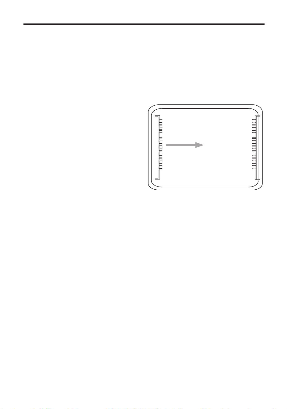
Shelf Runners
• Shelf runners can be removed to
enable you to clean them thoroughly.
Make sure they are cool to touch and
then grasp the runners and slide out
of their hanging holes.
Pull out to clean
CLEANING
12.110
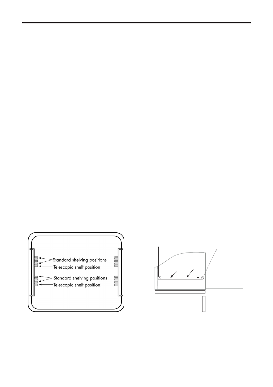
TELESCOPIC SHELVING SYSTEM
(if tted)
• In addition to the traditional shelving
ttedinyourappliance,thetele-
scopicshelvingsystemisttedinthe
most commonly used location in your
cavity.
• The shelves with the telescopic
system are easier to pull out than
traditional shelving, which means the
oven door stays open for a shorter
period of time. The smooth action
also reduces the likelihood of fat, or
food, spillage, and gives you extra
security.
• You do not have to use the telescopic
shelves all of the time. You can place
the shelves in the traditional positions
if you would like more choice.
• The telescopic shelves remove easily
from the runner for re-positioning
or cleaning, but we recommend that
you reposition your shelving before
cooking, and remove the shelving for
cleaning when the shelves are cold to
prevent burning yourself.
To remove the telescopic shelves
• Make sure the shelf is cool enough to
touch.
• Push the oven shelf back into the
cavity, until it hits the stop position.
• Grasp the shelf bars in the centre,
and lift the back of the shelf clear of
the stop position.
• You can then lift the front of the shelf
clear of the retaining tabs.
To replace the telescopic shelves
• Make sure the oven runners are
pushed all the way back into the
cavity.
• Tilt the shelf and make sure the front
of the shelf is against the stop posi-
tion.
• Carefully place the shelf back onto
therunnerandsnapinplacermly.
• Make sure the back of the self is
inside the retaining tabs and slide it
in and out of the oven to make sure
it works correctly.
1. Grasp and
lift shelf bars
2. Lift shelf
clear
Note: Make sure the shelf is
unclipped from the retaining
tabs before removal.
Make sure the shelf
is firmly pressed against
the stop position at
back of the oven cavity

INSTALLATION
Before you start: Please read the instruc-
tions. Planning your installation will save
you time and effort.
Prior to installation, ensure that the local
distribution conditions (nature of the gas
and gas pressure) and the adjustment of
the appliance are compatible. The adjust-
ment conditions are stated on the data
badge.
This appliance is not connected to a com-
bustion evacuation device. It shall be in-
stalled and connected in accordance with
current installation regulation. Particular
attention shall be given to the relevant
requirements regarding ventilation.
In your own interest and that of safety,
it is the law that all gas appliances be
installed and serviced by competent per-
sons. Gas Safe registered installers under-
take to work to satisfactory standards.
Where regulations or standards have been
revised since this handbook was printed,
always use the latest edition.
IN THE UK THE REGULATIONS AND
STANDARDS ARE AS FOLLOWS:
1. Gas Safety Regulations (Installation
and Use).
2. Building Regulations - Issued by the
Department of the Environment.
3. Building Standards (Scotland)
(Consolidated) - Issued by the Scottish
Development Department.
4. The current I.E.E. Wiring Regulations.
5. Electricity at Work Regulations.
6. BS 6172 Installation of Domestic Gas
cooking Appliances.
7. Installation & Servicing Instructions for
this appliance.
For installation in countries other than the
UK, the appliance must be connected in
accordance with all local gas and electrical
regulations.
In the Republic of Ireland, Installers
should refer to IS813 Domestic Gas Appli-
ances.
Ventilation Requirements
The room containing the appliance should
have an air supply in accordance with BS
5440: Part 2.
•Allroomsrequireanopenablewindow,
or equivalent, and some rooms will re-
quire a permanent vent as well.
•Forroomvolumesupto5m
3
an air vent
of 100cm
2
is required.
•Iftheroomhasadoorthatopensdi-
rectly to the outside, or the room exceeds
10m
3
, NO AIR VENT is required.
•Forroomvolumesbetween5m
3
and
10m
3
an air vent of 50cm
2
is required.
•Ifthereareotherfuelburningappli-
ances in the same room, BS 5440: Part 2
should be consulted to determine the air
vent requirements.
•Thisappliancemustnotbeinstalledina
bed sitting room of less than 20m
3
or in a
bathroom or shower room.
Windows and permanent vents should
therefore not be blocked or removed
withoutrstconsultingaGasSafegas
installer.
In the Republic of Ireland, refer to rel-
evant Irish Standards for correct ventila-
tion requirements.
Failure to install appliances correctly is
dangerous and could lead to prosecution.
This appliance is not connected to a
combustion products evacuation device.
It shall be installed and connected in ac-
cordance with current installation regula-
tions. Particular attention shall be given
to the relevant requirements regarding
ventilation.
INSTALLATION - 60CM
STEP 1 : PREPARE INSTALLATION
Do not lift the appliance by the door
handle.
Whilst every care is taken to elimi-
nate burrs and raw edges from this
product,please take care when handling
- we recommend the use of protective
gloves during installation.
Please note that the weight of this
appliance is approximately 31kg
(unpacked). Take care when lifting it
into the housing unit - always use an
appropriate method of lifting.
Removethexingscrewsfromthe
polythene bag on the top of the appli-
ance, but leave the appliance in the base
tray packaging until you are ready to
install it.
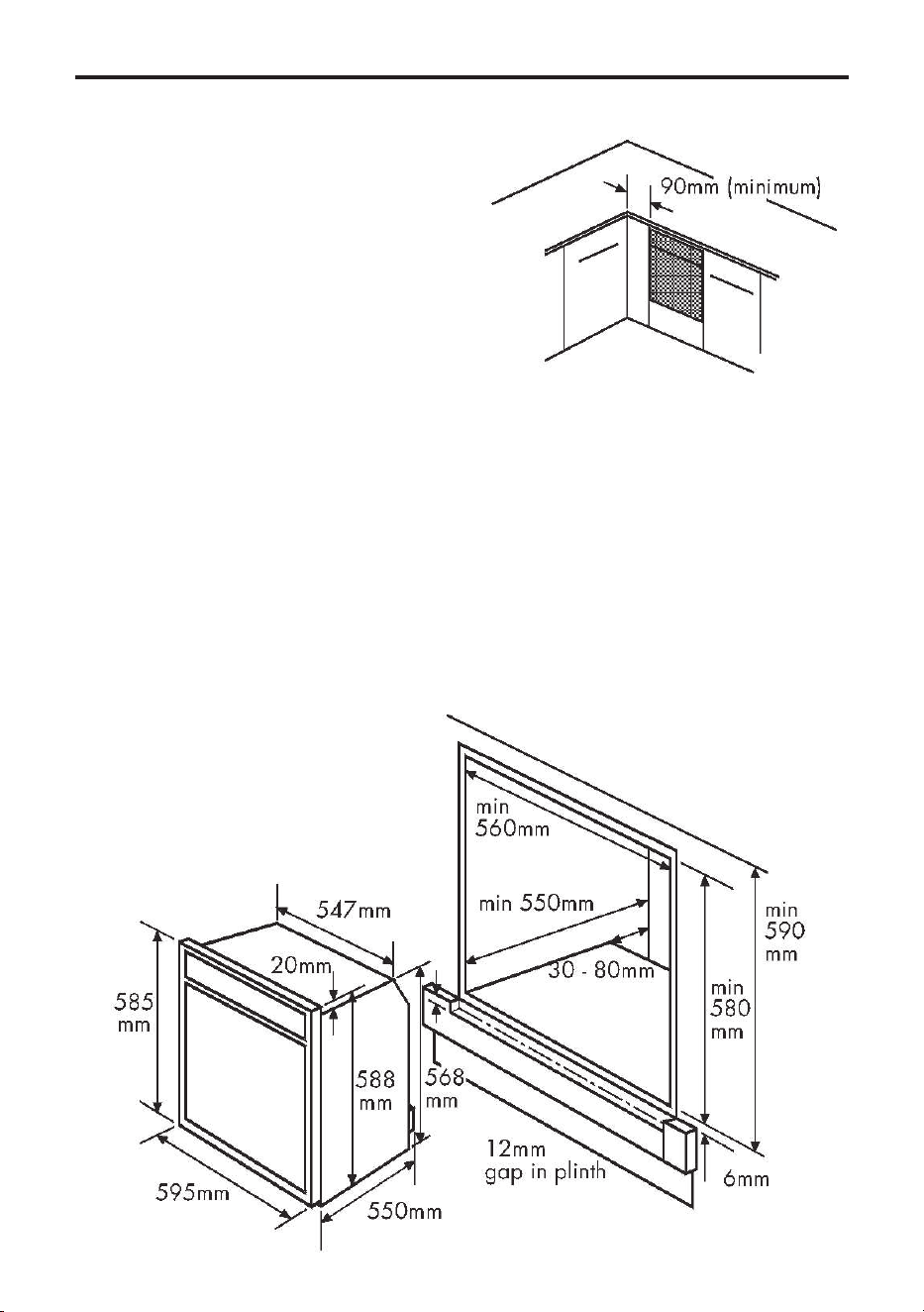
If this appliance is to be installed near to
a corner where the adjacent cabinets run
at right angles forward of the appliance,
there must be a gap of at least 90 mm
between the appliance and the cabinets,
to prevent overheating of the cabinets.
Housing dimensions
Theapplianceisdesignedtotintoa
standard 600mm wide housing unit with
minimum internal dimensions as shown.
590mm is to the underside of the worktop
when the appliance is built under, or to
the underside of the panel above, when
the appliance is installed into a tall
housing unit.
INSTALLATION - 60CM
i) When installed in a typical 600mm
deep built in housing unit, the false back
should be removed from the housing unit
to provide the necessary depth for
installation.
ii) When the false back is removed, it is
normally the case that the support shelf
for the appliance leaves a gap between
the back edge and the wall of
approximately 80mm.
iii) If no gap occurs between the back
edge of the shelf and the wall behind the
unit, we recommend that a gap of at least
30mm is made by shortening the shelf.
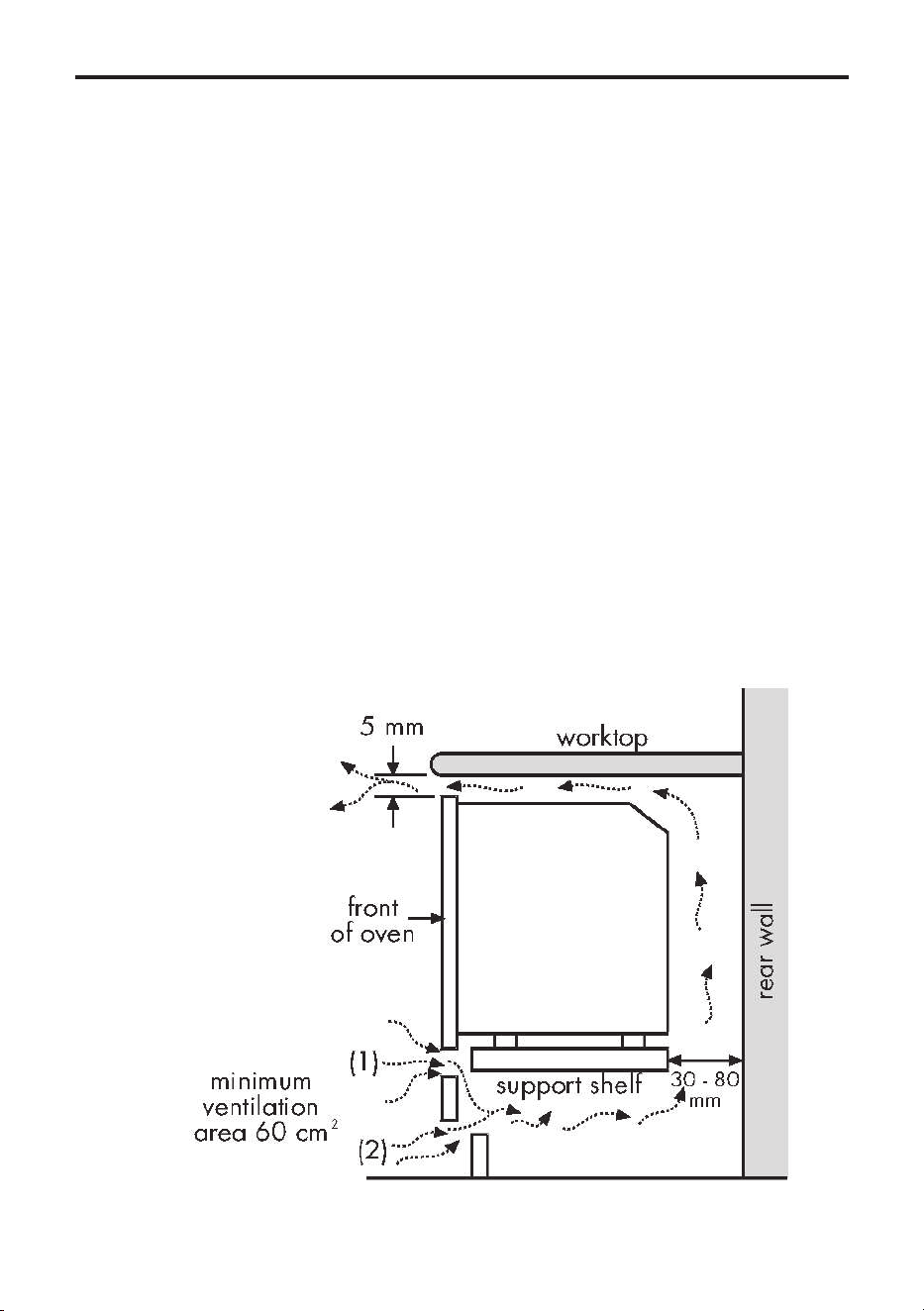
iv) When installing the appliance below a
worktop, there must be a minimum
ventilation area of 60cm2 below the
appliance, in either area (1) or (2), as
indicated below. There must be a 5mm
gap between the front top edge of the
oven and the underside of the worktop.
Important:
Do not modify the outer pan-
els of this appliance in any way.
Ensure that you route all mains electrical
cablesandexibletubingwellclearof
any adjacent heat source, such as an
oven, grill or hob.
Ensure that all pipe work is of the correct
ratingforbothsizeandtemperature.
Installing the appliance under a
worktop
Where the appliance is installed under
a worktop, with a hob installed above it,
the installation instructions for the hob
must be read in conjunction with these
instructions.

INSTALLATION - 70CM
Before you start
Please read the instructions carefully -
planning your installation will save you
time and effort.
Look at the different ways the appliance
can be installed - as shown on the
following pages - and plan the installation
to suit your situation.
Leave the appliance in the base tray
packaging until you are ready to install
it. When you remove the appliance from
the base tray packaging, take care not to
damage it.
Whilst every care is taken to eliminate
burrs and raw edges from this product,
please take care when handling - we
recommend the use of protective gloves
during installation.
Please note that the weight of this
appliance is approximately 47kg
(unpacked). Take care when lifting it into
the housing unit - always use an appro-
priate method of lifting.
This appliance must be installed only at
low level - ie; under a worktop. The
controls have been designed for viewing
at a low level, and it should therefore not
be installed at high level.
Pleasenotethatalldimensionsandsizes
given are nominal, some variation is to be
expected.
If this appliance is to be installed near to
a corner where the adjacent cabinets run
at right angles forward of the appliance,
there must be a gap of at least 90mm
between the appliance and the cabinets,
to prevent overheating of the cabinets.
Important: Do not modify the outer
panels of this appliance in any way.
Fixingscrews-Thexingscrewsareina
polythene bag in the oven pack. Depend-
ing on the method of installation, some of
the screws may not be needed.
STEP 1: PREPARE FOR INSTALLA-
TION
There are 3 methods of installing the ap-
pliance:
• Method 1: Into a space between two
base units, ie; without a housing
unit.
• Method 2: Into a housing unit,
with an internal height of less than
710mm,whichcanbemodiedto
obtain the required dimensions.
• Method 3: Into a housing unit, with
an internal height of 710mm or
more. If you have a non standard
sizeofcabinetwhichleavesagap
above or below the appliance, you
maybeabletobuyatrimkit(toll
in the gap) from the supplier of your
cabinets.
Quantity Colour Description For Fixing
6 Silver No 8 x 12mm long
Self tapping screw
Runners to appliance
12 Black No 8 x 12mm long
Chipboard screw
Runners and sidetrims to
cabinet or housing
6 Black No 8 x 25mm long
Chipboard screw
Appliance to cabinet
2 Silver No 8 x 12mm long
Self tapping screw
Appliance to sidetrims
INSTALLATION - 70CM
METHOD 1: WITHOUT HOUSING
UNIT(BETWEEN 2 BASE UNITS)
Before installing the appliance, check the
internal dimensions as shown.
The space for the appliance must be clear
of obstruction. You may have to cut into
or remove any rear cross members to
obtain the 550mm minimum depth.
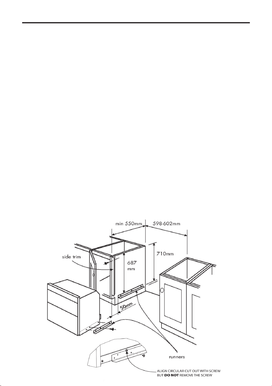
The Fixing Kit
Shouldyouneedareplacementxingkit
please call the customer care helpline and
order part number: 01 28287 00.
Inthexingkityouwillnd2sidetrims
(687mm long) and 4 runners (420mm
long).Thexingscrewsareinapoly-
thene bag in the oven.
1. Take the 6 No 8 x 12mm (silver) self
tapping screws from the polythene bag,
andusethemtotonerunnertoeach
side of the appliance.
2. Make sure they are the right way up as
shown.
3. Take one of the side trims, hold it
against the side of the base unit, and
mark off 687mm from the top edge of the
base unit, to the top edge of the runner.
Note: This ensures a 5 - 8mm clearance
from the underside of the worktop to the
top of the appliance.
4. Measure 50mm from the front edge of
the base units, to mark the front edge of
the runners.
5. Take 6 of the No 8 x 12mm (Black)
chipboard screws and screw the run-
ners into opposition the right way up as
shown.
6.Fitthesidetrimstobeushtothetop
and front edges of the base units, using
the remaining 6 No 8 x 12mm (Black)
chipboard screws.
INSTALLATION - 70CM
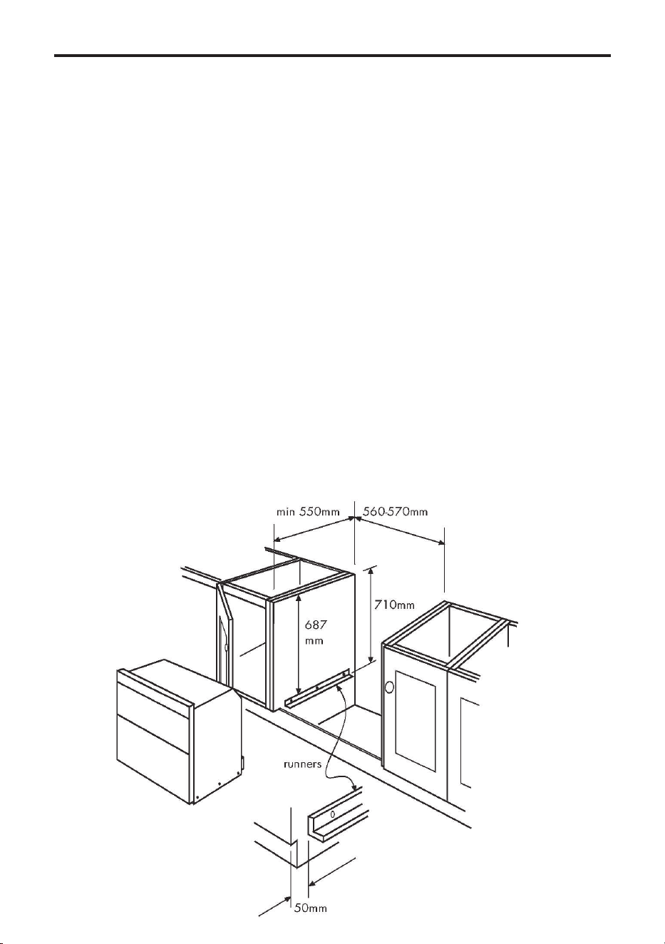
METHOD 2: HOUSING UNIT WITH
internal height less than 710mm.
Note: You will not need the 2 side trims
(687mm long) or the appliance runners
for this installation. You will need the 2
runnerstoxtotheadjacentcabinets.
Before you start;
Before removing the bottom shelf or
modifying the housing unit, make sure
that it will remain structurally sound, eg;
byxingtoadjacentcabinets,ooror
worktop.
You may have to cut into or remove any
rear cross members to obtain the 550mm
minimum depth.
To obtain the required 710mm height,
you may have to lower or remove the
bottom shelf - remove any cross rails and
reposition brackets.
To x the runners (if required)
1. Take the side trims, hold it against the
side of the base unit, and use it to mark
off the 687mm from the top edge of the
side unit, to the top edge for the runner.
Note: This ensures a 5 - 8mm clearance
from the underside of the worktop to the
top of the appliance.
2. Measure 50mm from the front edges of
the base units, to mark the front edge for
the runners.
3. Take 6 of the No 8 x 12mm (Black)
chipboard screws and screw the runners
into position the right way up as shown.
4. If necessary, adjust the height of the
plinth to just below the bottom edge of
the runners.
Ifyourequireareplacementxingkit
please call the customer care helpline and
order part number 01 28287 00.
INSTALLATION - 70CM
METHOD 3: UNDER WORKTOP WITH
INTERNAL HEIGHT OF 710MM OR
MORE
Note: You will not need the 4 runners and
2 trims that are packed with the oven for
this installation.
1. When installed in a typical 600mm
deep built in housing unit, the false back
should be removed from the housing unit
to provide the necessary depth for
installation.
2. When the false back is removed, it is
normally the case that the support shelf
for the appliance leaves a gap between
the back edge and the wall of approxi-
mately 80mm.
3. If no gap occurs between the back
edge of the shelf and the wall behind the
unit, you must create a gap of at least
30mm by shortening the shelf.
Removeanyxingsthatmayprevent
entry of the oven into housing, or
obstruct the gas inlet pipe. The cabinetry
should be kept structurally sound by
xingtoadjacentcabinets,ooror
worktop.
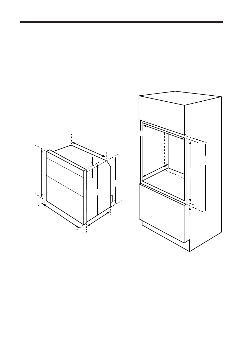
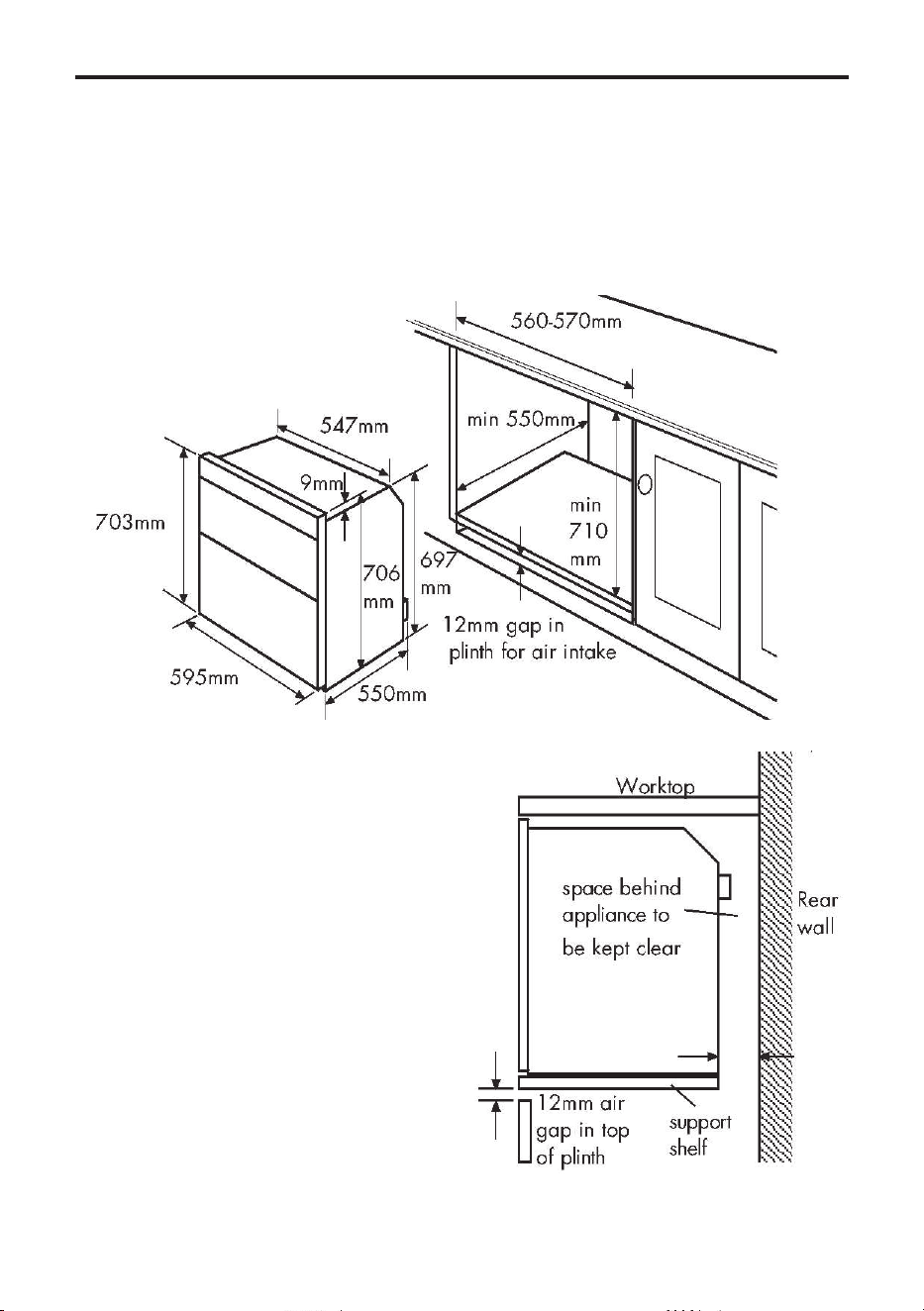
METHOD 4: TALL HOUSING UNIT
WITH INTERNAL HEIGHT 700MM OR
MORE
Theappliancecantintoa600mmwide
housing unit with minimum internal
dimensionsasshown.Note:allsizesare
nominal, some variation is to be expected.
703mm
595mm
550mm
547mm
9mm
706mm
697mm
min
550mm
min
700mm
min 560mm
30-80mm
min
710mm
min
6mm
REFER TO 90CM INSTALLATION INSTRUCTIONS FOR REQUIRED AIR GAPS
INSTALLATION - 70CM
INSTALLATION - 90CM
STEP 1 : PREPARE INSTALLATION
Do not lift the appliance by the door
handle.
Removethexingscrewsfromthe
polythene bag on the top of the appli-
ance,
but leave the appliance in the base tray
packaging until you are ready to install it.
Whilst every care is taken to eliminate
burrs and raw edges from this appliance,
please take care when handling - we
recommend the use of protective gloves
during installation.
Please note that the weight of this
appliance is approximately 48kg
(unpacked). Take care when lifting it
into the housing unit - always use an
appropriate method of lifting.
Note: When removing the appliance from
the base tray packaging care should
be taken to ensure the appliance is not
damaged.
Siting the appliance
If this appliance is to be installed near to
a corner where the adjacent cabinets run
at right angles forward of the appliance,
there must be a gap of at least 90mm
between the appliance and the cabinets,
to prevent overheating of the cabinets.
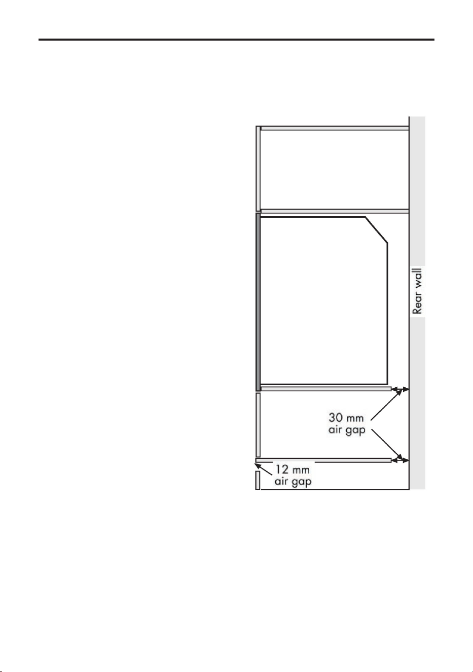
When installed in a typical 600mm
deep built in housing unit, the false back
should be removed from the housing
unit, to provide the necessary depth for
installation.
When the false back is removed, it is
normally the case that the support shelf
for the appliance leaves a gap between
the back edge of the support shelf and
the rear wall of approximately 80mm.
If no gap occurs between the back edge
of the shelf and the wall behind the unit,
you must create a gap of at least 30mm
by shortening the shelf and any other
shelf below the appliance.
Cut 12mm from the top of any plinth that
maybetted(seediagram).
Important: Do not modify the outer
panels of this appliance in any way.
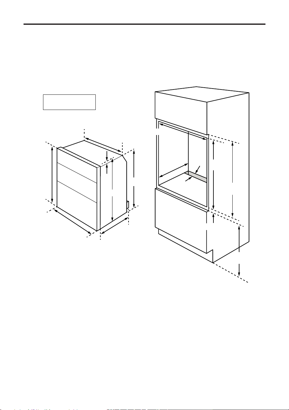
INSTALLATION - 90CM
Dimensions
Theapplianceisdesignedtotintoa
standard 600mm wide housing unit, with
minimum internal dimensions as shown.
Note:Allsizesarenominal,somevariation
is to be expected.
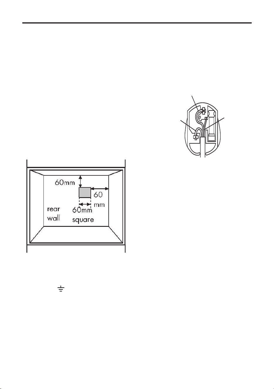
Step 2 : Connect to gas supply
1. The inlet to the appliance is ISO 7
- Rp ½” internal thread situated
towards the top right hand rear corner.
2. Fit the bayonet connection to the wall
in shaded area as shown.
The shaded area shown is applicable to
installations in minimum depth cabinets.
If more room is available, the bayonet
xingareacanbeextended,providedthat
theexibletubedoesnotobscurethefan
intake.
3. Use a 900mm - 1125mm length of
exibleconnector.
Theexibleconnectorshallbettedsuch
that it cannot come into contact with a
moveable part of the housing unit (eg;
drawer) and does not pass through
any space susceptible of becoming
congested.
min
550mm
min
880mm
min
890mm
560mm
30-80mm
Min vent
60cm²
885mm
595mm
max 555mm
547mm
20mm
888mm
868mm
min 6mm
830mm
AU ONLY
Built-In
90cm Gas and Electric
INSTALLATION
Makesurethattheexible
connector does not block the cooling
fan inlet.
4. Flexible connections should comply
with BS 669.
Parts of the appliance likely to come into
contactwithaexibleconnectorhavea
temperature rise of less than 70°C.
5. Rigid connections must be accessible
to disconnect for servicing.
Cut a 150mm square hole in the right
hand rear corner of the support shelf for
the supply pipe.
6. Make sure all connections are gas
sound.
Step 3 : Connect to the electricity
supply
Warning: This appliance must be
earthed.
For products tted with a plug
Theexiblemainsleadissuppliedcon-
nected to a BS 1363 fused plug, the plug
isttedwiththecorrectfuse.
Replace only with a fuse of the same rat-
ing and type.
The wires in the mains lead are coloured
in accordance with the following code:
Green and yellow = Earth,
Blue = Neutral,
Brown = Live.
As the colours of the wires in the mains
lead for the appliance may not correspond
with the coloured markings identifying the
terminals in your plug, proceed as follows:
1. The wire which is coloured green and
yellow must be connected to the terminal
marked E (Earth) or coloured Green.
2. The wire which is coloured blue must
be connected to the terminal marked N
(Neutral), or coloured Black.
3. The wire which is coloured brown must
be connected to the terminal marked L
(Live), or coloured Red.
The plug and socket must be accessible
after installation. Should the mains lead of
the appliance ever require replacing, this
mustbecarriedoutbyaqualiedelectri-
cian who will replace it with a lead of the
samesizeandtemperaturerating.
Important: - ensure that you route all
mainsandelectricalcablesandexible
tubing well clear of any adjacent heat
source.
Under no circumstances should the mains
electric cable be allowed to come into
contactwiththeverticalovenuetubes
on the rear of the appliance.
E (Earth)
Green/Yellow
N (Neutral)
Blue
L (Live)
Brown

INSTALLATION
For products without a plug
This appliance must be connected by a
competentperson,usingxedwiringvia
a double pole switched fused spur outlet,
with a contact separation of 3mm at all
poles.
Use a 13 amp fuse.
We recommend that the appliance is
connectedbyaqualiedelectrician,
who will comply with the I.E.E. and local
regulations.
Warning: This appliance must be earthed.
The wires in the mains lead are coloured
in accordance with the following code:
Green & Yellow = earth, Blue = neutral,
Brown = live.
Typical example of a double pole
fuse spur outlet
As the colours of the wires in the mains
lead for the appliance may not cor-
respond with the coloured markings
identifying the terminals in your spur box,
proceed as follows:
1. The wire which is coloured green and
yellow must be connected to the
terminal marked E (Earth) or coloured
green.
2. The wire which is coloured blue must
be connected to the terminal marked
N (Neutral) LOAD or coloured Black.
3. The wire which is coloured brown must
be connected to the terminal marked L
(Live) LOAD or coloured Red.
If the supply cord is damaged, obtain a
special cord from the Customer Support
Helpline,whichmustbettedbya
qualiedperson.
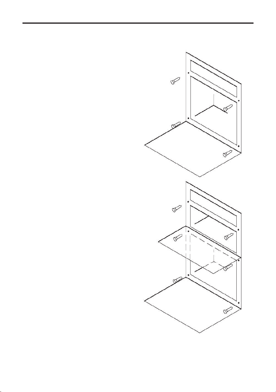
INSTALLATION
Step 4: Secure appliance into hous-
ing unit
Note : The unit housing the appliance
mustbeappropriatelyxed.Ensurethat
the appliance is centrally located. Take
care not to damage the appliance or
cabinetry.
70cm only
Method 1 : Care must be taken to ensure
theappliancerunnersaresufciently
engaged over the top of the runners on
the base units.
Method 2 : Insert appliance into the cabi-
net - ensure that it is engaged over the
top of the side runners.
Method 3 : Insert appliance into cabinet
Note: For installation Method 1, you will
needtodrillthroughthexingholesinto
the side trims with a 3.2mm diameter
drill.
There are 4/6 black no 8 x 25mm long
chipboard screws for securing appliance
to cabinet. Insert appliance into cabinet
and secure.
60cm ovens
- Open the oven door and screw the 4
xingscrewsthroughtheholesinthe
front frame.
70/90cm ovens
- Open the grill / top oven door, and
screw2xingscrewsthroughthetopcor-
ner holes in the front frame.
- With the grill / top oven door still open,
screw2xingscrewsthroughtheholes
located under the grill compartment.
Close the grill / top oven door.
- Open the main oven door and screw 2
xingscrewsthroughthebottomcorner
holes in the front frame.
60/70/90 xing positions
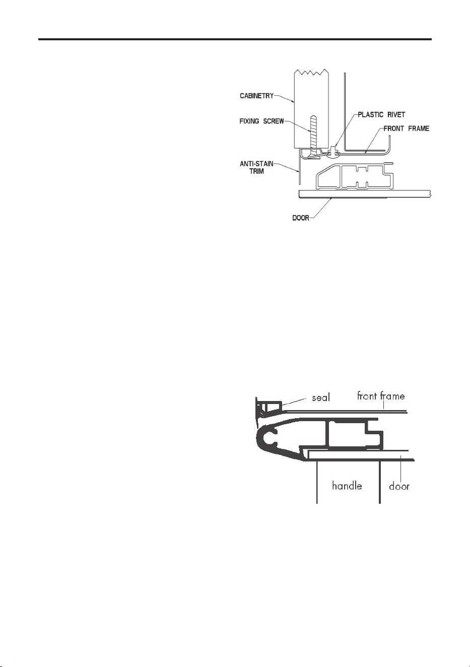
INSTALLATION
Anti-stain trim (if tted)
Theanti-staintrimisfactoryttedto
the edges of the appliance front frame.
This trim provides the cabinetry with
extra protection from any escape of heat.
- When Installing the product, ensure
the anti-stain trim is correctly located
on the edges of the front frame, before
positioning and securing the appliance to
the cabinet.
-Whensecuringtheappliance,thexing
screws provided are driven through the
anti-stain trim into the cabinet.
Note : When supplied the anti-stain trim
may be loose and is only supported by
plastic rivets. The anti-stain trim will be
securedwhenthexingscrewsarefully
home into the cabinet. The plastic rivets
should not be removed.
Edging strip (if tted)
Theedgingstripisfactoryttedto
the edges of the appliance front frame.
This strip provides the cabinetry with
extra protection from any escape of heat.
When installing the product, ensure
that the edging strip is correctly located
on the outer edges of the front frame,
before positioning and securing the
appliance to the cabinet.
Whensecuringtheappliance,thexing
screws provided are driven through the
edging strips into the cabinet - the seal
willstraightenupandsitushtothe
cabinet when the screws are fully home.

INSTALLATION
Commissioning
Pressure test point
Use the oven burner. From inside the
oven remove the burner cowl. Remove
the small screw at the LHS of the burner
cradle. Slide the burner to the left to ac-
cess the injector.
Connect suitable T-piece (incorporating
a 115 injector) to the injector. Connect
manometer to the T-piece, and turn oven
control to full on to check pressure.
Replace in reverse order.
Burner aeration
Allburnershavexedaerationandno
adjustment is possible.
Pressure setting
See technical data.
Electrical systems check
In the event of an electrical fault the
preliminary electrical system check (earth
continuity, short circuit, polarity and resis-
tance to earth) must be carried out.
Ignition check
Oven ignition:
Push in and turn the main oven control
knob anti clockwise to the ‘FULL ON’
position. The ignition system will spark
automatically. Push in the control knob to
ignite the gas. The sparking will stop. If
after 15 seconds, the burner has not lit,
turn off the oven and leave the compart-
ment door open. Wait at least one minute
before a further attempt to ignite the
burner.
Do not hold the control knob in for more
than 15 seconds.
Turn the control knob clockwise to the
required setting.
To turn off, return the control knob to the
“off” position.
Grill ignition:
1. The door must be open for grilling.
2. Push in and turn the control knob
clockwise to the grill symbol.
Before leaving the installation
Show the customer how to ignite the
oven and operate the grill and give them
this handbook. Thank you.
TECHNICAL DATA
14.000
Data badge
Lower part of front frame and rear of
appliance
Pressure setting
G20 Natural Gas @ 20 mbar
G30 Butane @ 28-30 mbar
G31 Propane @ 37 mbar
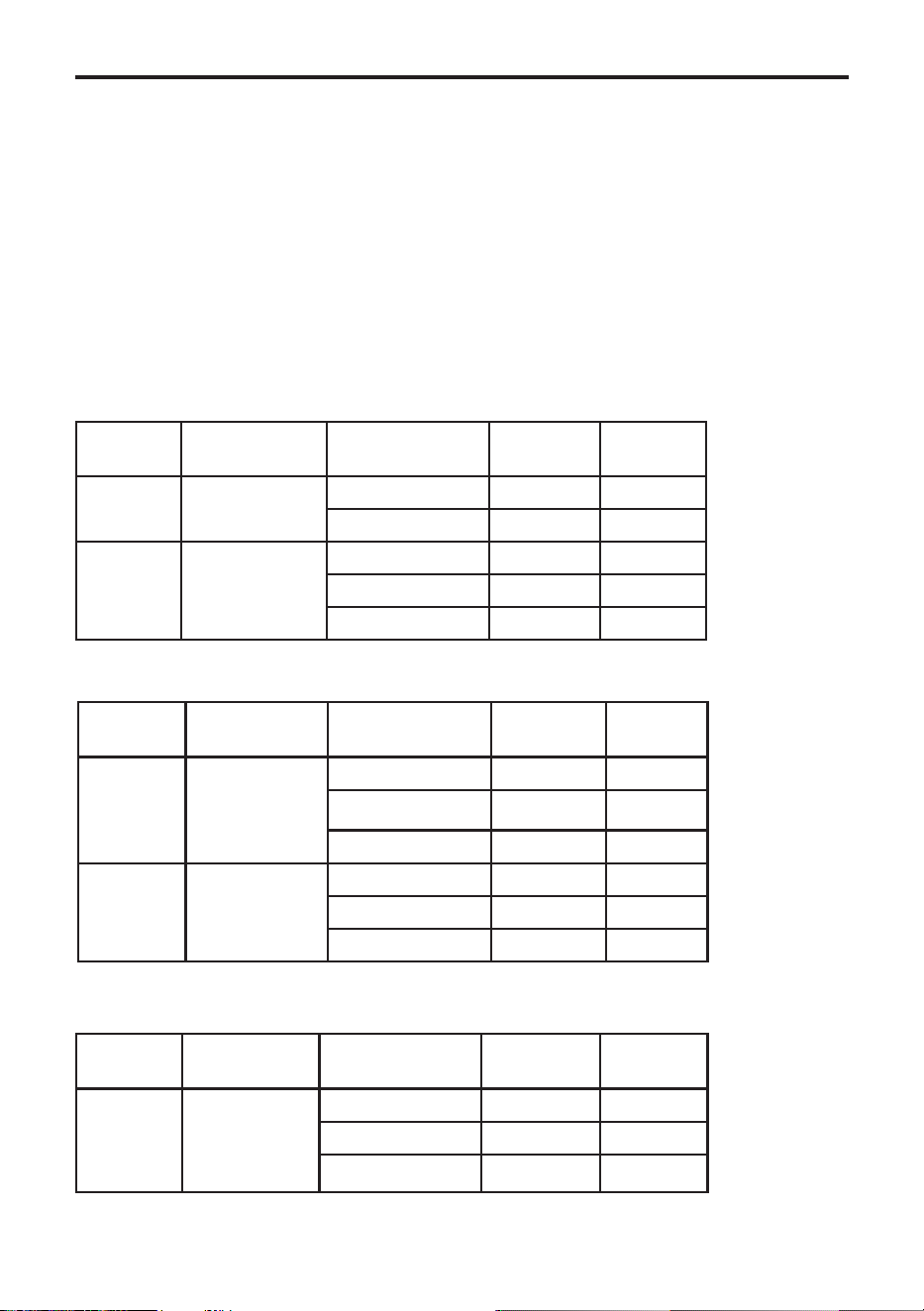
GAS DATA
60cm
70/90cm - Oven & Grill
70/90cm - Double Oven
Appliance class
Class 3, built-in oven and grill
Countries of destination
GB - Great Britain, IE - Ireland
Electrical supply
220-240V~50Hz
MAX.2660W.(Ifttedwithelectricgrill).
Warning: This cooker must be earthed.
Gas Type Gas
Category
Burner Nominal
Rate On
Injector
Size
Nat Gas I
2H
(20) Oven 2.5kW 1.15mm
Grill 2.25kw 1.12mm
Total heat input 4.75kw
LPG I
3+
(28-31/37) Oven 2.5kW 70 AMAL
Grill 2.3kW 0.74mm
Total heat input 4.8kW
Gas Gas
Category
Burner Nominal
Rate On
Injector
Size
Nat Gas I
2H
(20) Oven 2.5kW 1.15mm
Total heat input 2.5kW
LPG I
3+
(28-31/37) Oven 2.5kw 70 AMAL
Grill 2.3kw 0.74mm
Total heat input 2.5kw
Gas Gas
Category
Burner Nominal
Rate On
Injector
Size
Nat Gas I
2H
(20) Main Oven 2.5kW 1.15mm
Top Oven 1.8kW 130 AMAL
Total heat input 4.3kW

CUSTOMER CARE
FAQs
What parts of the appliance can be
washed in a dishwasher?
• Any enamelled parts such as the grill
pan can be cleaned in a dishwasher,
as can oven shelves and shelf guides.
What parts must NOT be cleaned in a
dishwasher?
• Parts such as burner skirts and caps,
control knobs and any cast iron items
must not be cleaned in a dishwasher,
they should be cleaned with hot
soapy water and a nylon brush once
they are cool enough.
There’s been a power failure and the
product won’t work.
• Switch off the electricity supply.
• When the power returns switch the
electricity supply back on and re-set
any programmer/clock to the correct
time of day.
My oven is a single combined oven
and grill - can I use both functions
together?
• No. You can only use one or the
other.
Why is there condensation on the
doors?
• Condensation is caused by hot, moist
air meeting a cooler surface (i.e. the
oven door). You cannot always pre-
vent it, but you can minimise it when
it happens by doing the following:
• Preheat the oven at a high tempera-
ture before putting food in the oven,
and cover the food you are cooking
wherever possible.
• Whenever you can, cook wet foods at
higher temperatures.
• Don’t leave food in the oven to cool
down.
• Automatic cooking will normally pro-
duce condensation when the oven is
cooling down with food inside.
Should the cooling fan continue to
run once the appliance has been
switched off?
• Yes. This is to make sure that you
can always touch the control knobs to
make temperature adjustments, and
turn your appliance off.
Can all gas appliances be converted
from Natural Gas to LP Gas?
• Not all gas appliances can be con-
verted. If Category II is stated on
the databadge, then the appliance
may be converted and a conversion
kit must be obtained if not already
provided. If in doubt, please contact
Customer Care for further advice - do
not attempt to convert an appliance if
it is not compatible.
Why won’t the ignition work?
• Check there is a spark when the igni-
tion button is depressed. If there is
no spark, check the electricity supply
is switched on at the socket. Check
that the gas supply is switched on.
Call Customer Care for a Service
Engineer’s visit if:
• Youndthattheovenbecomeshot-
ter at a particular temperature - the
thermostat may need replacing.
• The cooling fan fails to work.

CUSTOMER CARE
15.030
CUSTOMER CARE WEB SHOP
Having purchased a superior cooker, hob
or hood from us, you’ll naturally want to
keep it looking great. And who better to
help you care for it than the manufac-
turer?
We offer an extensive range of accesso-
ries, components and cleaning products
which, will instantly give your cooker a
good as new look.
In addition to the list of our most popular
products below, we also have an exciting
range of Bake ware and Cookware essen-
tials including Roasting Pans, Cake Tins
and Non-Stick Cooking Liners.
For all enquires, please visit our Web
Shop at www.gdhaonline.co.uk or
call the Spares Sales Team on 0844
815 3745. For countries outside the UK,
please contact your local service agent.
Product De-
scription
Where used Purpose
Ceramic Hob
Cleaner
All Ceramic glass
hobs including
Induction
Enables easier cleaning of your ceramic hob.
Prevents build up of mineral deposits. Best
used with Ceramic Hob Scraper Kit. 300ml
bottle.
Ceramic Hob
Scraper kit
All Ceramic glass
hobs including
Induction
Ideal for removing cooked on marks from
ceramic glass hobs Best used with Ceramic
Hob Cleaner
Sealed Hotplate
Conditioner
All sealed/solid
plate hobs
Restoresthesleekmattblacknishtosolid
hotplates
Multipurpose
Kitchen Cleaner
General kitchen
cleaner
Excellent multipurpose cleaner, For use
around the kitchen. 500ml bottle.
Oven Cleaner
All cooking appli-
ances.
Cuts through grease & burnt on grime. 500ml
bottle
Restor-A-Cloth
All cooking appli-
ances.
Chemical free cleaning cloth Ideal for clean-
ing & polishing glass & stainless steel
Stainless Steel
Cleaner
All stainless steel
parts
Oil based cleaner. Perfect for removing stub-
born & greasy marks. 300ml bottle.
Rectangular car-
bonlters
Cooker Hoods
Newlters,helptomaintainefcientcooker
hood operation and keep your Kitchen odour
free
Round Carbon
Filters
Cooker Hoods
Newlters,helptomaintainefcientcooker
hood operation and keep your Kitchen odour
free

CUSTOMER CARE
15.040
CUSTOMER CARE
CHANGING LIGHT BULBS
(where tted)
Warning: There is a risk of electric shock, so always make sure you have turned off
and unplugged your appliance before starting. Always allow the product to cool down
before you change a bulb.
Not all appliances have the same number and type of bulbs. Before replacing your
bulb, open the oven door and see which type you have. Then use the table to help you
change your bulb correctly.
Bulbs can be purchased from hardwarestores (always take the old bulb with you).
Please remember that bulbs are not covered by your warranty.
No of Lamps Instructions
1 Remove the oven shelves.
Unscrew the lens cover by turning anticlockwise.
Remove the bulb and replace.
Replace the lens cover and oven back.

Pleasekeepthishandbookforfuturereference,orforanyoneelse
whomayusetheappliance.
CUSTOMER CARECUSTOMER CARE
To contact Stoves about your appliance, please call
Warranty Registration
0800 952 1065
to register your appliance
Customer Care Helpline
0344 815 3740
incaseofdifcultywithintheUK
Alternatively general, spares and service information is available from our website at
www.stoves.co.uk
Please ensure that you have the product’s model no and serial no available when you
call. These can be found on the silver data label on your product which is located:
Ovens Open the door; adjacent to the oven cavity
High-level grill products Inside the base compartment
Hobs On the underside of the product
Enter appliance numbers here for future reference:
Model No
Serial No
SERVICE RECORD
Date of purchase Installed by Installation Date
Place of purchase:
Date Part(s) replaced Engineer’s name
For customers outside the UK and Northern Ireland, please contact your local supplier.
Glen Dimplex Home Appliances, Stoney Lane, Prescot, Merseyside, L35 2XW