
WWW.ZEPHYRONLINE.COM
DEC21.0101
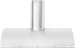
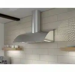
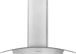
Okeanito
COK-E36CSX, COK-E42CSX, COK-E48CSX,
COK-E36CBGX, COK-E42CBGX, COK-E48CBGX
EN Use, Care, and Installation Guide
FR Guide d’utilisation, d’entretien et d’installation

2
Okeanito Use, Care, and Installation Guide
OKEANITO
WALL
DESIGNER

3
Okeanito Use, Care, and Installation Guide
ZEPHYRONLINE.COM
Contents
Page
Safety Information ............................................................................ 4-6
Types of Safety Warnings ................................................................... 4
General Safety ..................................................................................4-5
Operation ........................................................................................... 6
Electrical Requirements ...................................................................... 6
List of Materials ................................................................................... 7
Installation Instructions .....................................................................8-16
Ducting Calculation Sheet .................................................................. 8
Mounting Height, Clearance, & Ducting ............................................. 9
Ducting Options .................................................................................10
Hood Specifications ............................................................................ 11
Electrical Supply ................................................................................. 12
Cable Lock .........................................................................................12
Internal Blower Preparation ................................................................13
Remote Blower Preparation.................................................................14
Mounting the Range Hood ............................................................... 15-16
Features & Controls .......................................................................... 17-18
Touch Controls .................................................................................17-18
Maintenance ....................................................................................19-20
Hood & Grease Filter Cleaning ...........................................................19
Swivel LumiLight LED ......................................................................... 20
Wiring Diagram ................................................................................21-22
Troubleshooting............................................................................... 23-24
List of Parts & Accessories .................................................................. 25
Notes .................................................................................................. 26
Limited Warranty ............................................................................... 27
Product Registration ...........................................................................28
4
Okeanito Use, Care, and Installation Guide
OKEANITO
WALL
DESIGNER
Safety Information
Your safety and the safety of others are very important.
We have provided many important safety messages in this
manual for your appliance. Always read and obey all safety
messages.
This is the Safety Alert Symbol. This symbol alerts you to
potential hazards that can cause severe bodily injury or death.
All safety messages will follow the Safety Alert Symbol and either
the words “DANGER” “WARNING” or “CAUTION”
DANGER
Danger means that failure to heed this safety statement may
result in severe injury or death.
READ AND SAVE THESE INSTRUCTIONS
WARNING - TO REDUCE THE RISK OF FIRE, ELECTRIC SHOCK,
OR INJURY TO PERSONS, OBSERVE THE FOLLOWING:
a) Use this unit only in the manner intended by the
manufacturer. If you have questions, contact the manufacturer.
b) Before servicing or cleaning unit, switch power o at service
panel and lock the service disconnecting means to prevent
power from being switched on accidentally. When the service
disconnecting means cannot be locked, securely fasten a
prominent warning device, such as a tag, to the service panel.
General Safety
WARNING
Warning means that failure to heed this safety statement
may result in extensive product damage, serious personal
injury, or death.
CAUTION
Caution means that failure to heed this safety statement
may result in minor or moderate personal injury, property or
equipment damage.
WARNING
To reduce the risk of fire or electric shock, do not use this fan
with any solid-state control device.
WARNING
CAUTION
For General Ventilating Use Only. Do Not Use To Exhaust
Hazardous Or Explosive Materials And Vapors. Take care
when using cleaning agents or detergents. Suitable for use in
household cooking area.
WARNING
WARNING - TO REDUCE THE RISK OF A RANGE TOP GREASE
FIRE:
a) Never leave surface units unattended at high settings.
Boilovers cause smoking and greasy spillovers that may ignite.
Heat oils slowly on low or medium settings.
b) Always turn insert ON when cooking at high heat or
when flambeing food. (i.e. Crepes Suzette, Cherries Jubilee,
Peppercorn Beef Flambe’).
c) Clean ventilating fans frequently. Grease should not be
allowed to accumulate on fan or filter.
d) Use proper pan size. Always use cookware appropriate for
the size of the surface element.
5
Okeanito Use, Care, and Installation Guide
ZEPHYRONLINE.COM
Safety Information
WARNING
READ AND SAVE THESE INSTRUCTIONS
WARNING - TO REDUCE THE RISK OF INJURY TO PERSONS
IN THE EVENT OF A RANGE TOP GREASE FIRE, OBSERVE THE
FOLLOWINGa:
a) SMOTHER FLAMES with a close-fitting lid, cookie sheet, or
metal tray, then turn o the burner. BE CAREFUL TO PREVENT
BURNS. If the flames do not go out immediately, EVACUATE AND
CALL THE FIRE DEPARTMENT.
b) NEVER PICK UP A FLAMING PAN – You may be burned.
c) DO NOT USE WATER, including wet dishcloths or towels – a
violent steam explosion will result.
d) Use an extinguisher ONLY if:
1) You know you have a Class ABC extinguisher, and you
already know how to operate it.
2) The fire is small and contained in the area where it
started.
3) The fire department is being called.
4) You can fight the fire with your back to an exit
aBased on “Kitchen Firesafety Tips” published by NFPA.
WARNING
WARNING
TO REDUCE THE RISK OF FIRE, USE ONLY METAL DUCTWORK.
CAUTION
To reduce risk of fire and to properly exhaust air outside, do
not vent exhaust air into spaces within walls, ceilings, attics,
crawl spaces, or garages.
WARNING
WARNING - TO REDUCE THE RISK OF FIRE, ELECTRIC SHOCK,
OR INJURY TO PERSONS, OBSERVE THE FOLLOWING:
a) Installation work and electrical wiring must be done by
qualified person(s) in accordance with all applicable codes and
standards, including fire-rated construction.
b) Sucient air is needed for proper combustion and
exhausting of gases through the flue (chimney) of fuel burning
equipment to prevent back drafting. Follow the heating
equipment manufacturer’s guideline and safety standards such
as those published by the National Fire Protection Association
(NFPA), and the American Society for Heating, Refrigeration
and Air Conditioning Engineers (ASHRAE), and the local code
authorities.
c) When cutting or drilling into wall or ceiling, do not damage
electrical wiring and other hidden utilities.
d) Ducted fans must always be vented to the outdoors.
e) If this unit is to be installed over a tub or shower, it must be
marked as appropriate for the application and be connected
to a GFCI (Ground Fault Circuit Interrupter) - protected branch
circuit.
WARNING
Prop. 65 Warning for California Residents: This product may
contain chemicals known to the State of California to cause
cancer, birth defects, or other reproductive harm.

6
Okeanito Use, Care, and Installation Guide
OKEANITO
WALL
DESIGNER
Safety Information
Operation
► Always leave safety grilles and filters in place. Without these components, operating blowers could catch onto hair, fingers and
loose clothing.
► The manufacturer declines all responsibility in the event of failure to observe the instructions given here for installation,
maintenance and suitable use of the product. The manufacturer further declines all responsibility for injury due to negligence and
the warranty of the unit automatically expires due to improper maintenance.
NOTE: Please check www.zephyronline.com for revisions before doing any custom work.
Electrical Requirements
Important:
► Observe all governing codes and ordinances.
► It is the customer’s responsibility to be aware of these below:
► To contact a qualified electrical installer.
► To assure that the electrical installation is adequate and in conformance with National Electrical Code, ANSI/NFPA 70 latest
edition* or CSA standards C22.1-94, Canadian Electrical Code, Part 1 and C22.2 No.0-M91 - latest edition** and all local codes
and ordinances.
► If codes permit and a separate ground wire is used, it is recommended that a qualified electrician determine that the ground path
is adequate.
► Do not ground to a gas pipe.
► Check with a qualified electrician if you are not sure the insert is properly grounded.
► Do not have a fuse in the neutral or ground circuit.
► This appliance requires a 120V 60Hz electrical supply and connected to an individual properly grounded branch circuit protected
by a 15 or 20 ampere circuit breaker or time delay fuse. Wiring must be 2 wire with ground. Please also refer to Electrical Diagram
on product.
► A cable locking connector (not supplied) might also be required by local codes. Check with local requirements, purchase and
install appropriate connector if necessary.
* National Fire Protection Association Batterymarch Park, Quincy, Massachusetts 02269
** CSA International 8501 East Pleasant Valley Road, Cleveland, Ohio 44131-5575
READ AND SAVE THESE INSTRUCTIONS
7
Okeanito Use, Care, and Installation Guide
ZEPHYRONLINE.COM
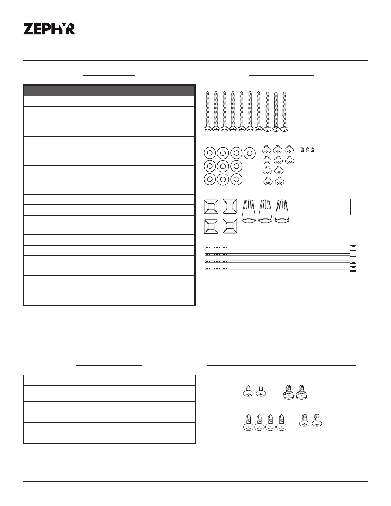
List of Materials
Parts Not Supplied
Ducting, conduit and all installation tools
Cable locking connector (if required by local
codes)
Single internal blower (CBI-290C, CBI-600A)
External blower (CBE-1000)
In-line blower (PBN-1000A)
Duct cover extension (Z1C-00OK)
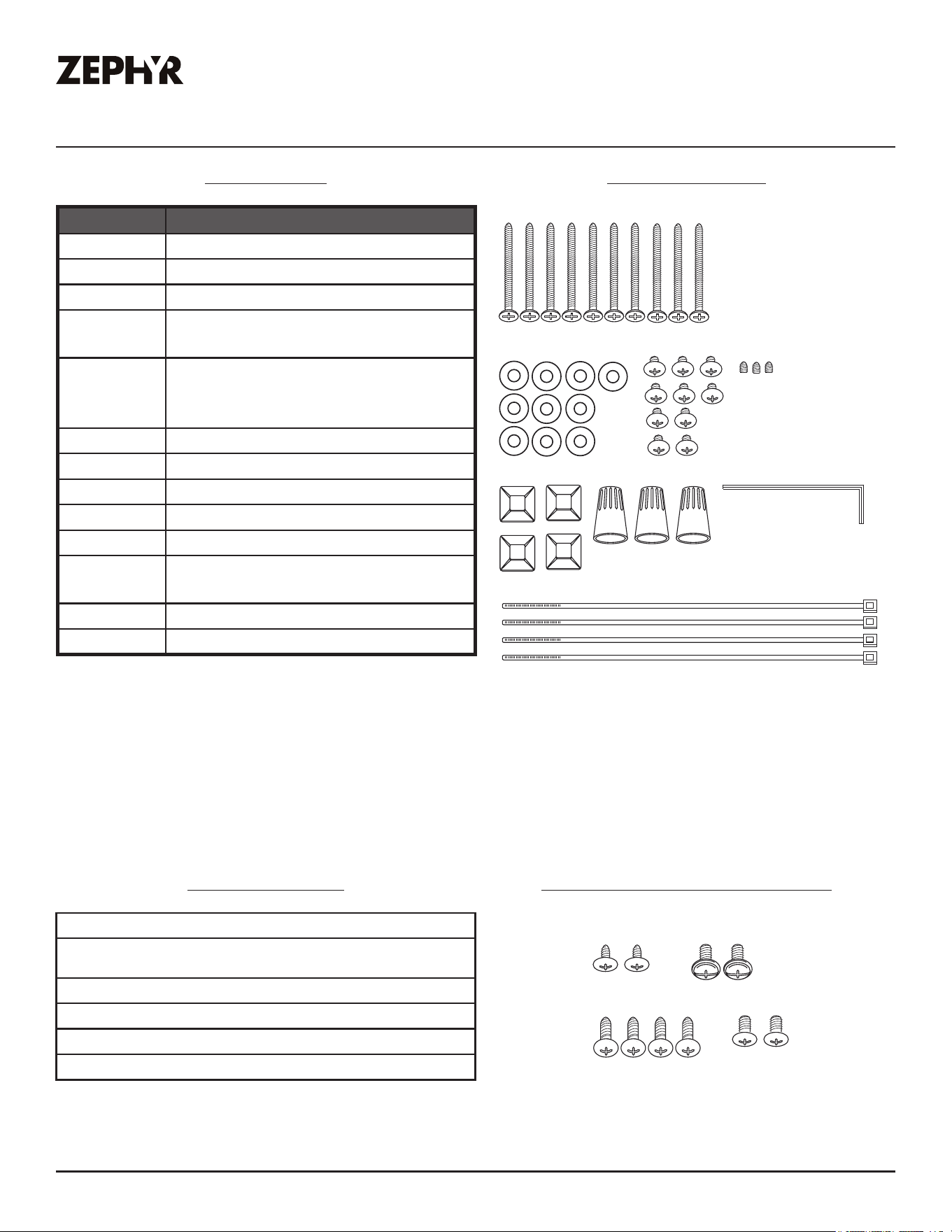
Parts Supplied
Quantity Part
1 Hood
1 Bae filters (36” & 42” models)
2 Bae filters (48” model)
2
Swivel LumiLight LED, 6W (pre-
installed) (36” & 42” models)
4
Swivel LumiLight LED, 6W (pre-
installed)
(48” model)
2 4W mood LED bulbs
2 Telescopic duct covers
1 Duct cover ceiling bracket
1 Utensil rail
1 Wall mount hanging bracket
1
8” round starting collar with
damper
1 Remote blower wire harness
1 Hardware package
M4 * 38 x 10
M4 * 8 x 10
Zip Tie x 4
Zip Tie Holder x 4
Wire Cap x 3
Allen Key x 1
Washer x 10
Set Screw x 3
(pre-installed into
utensil rail)
M4 * 8 x 2
M4 * 8 x 2
10x3/16” x 2
M4 * 16 x 4
Hardware Package
Internal Blower Hardware Package
8
Okeanito Use, Care, and Installation Guide
OKEANITO
WALL
DESIGNER
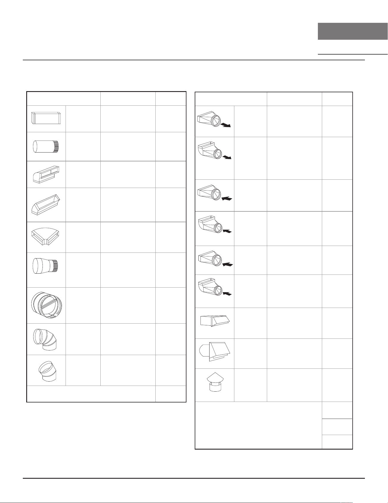
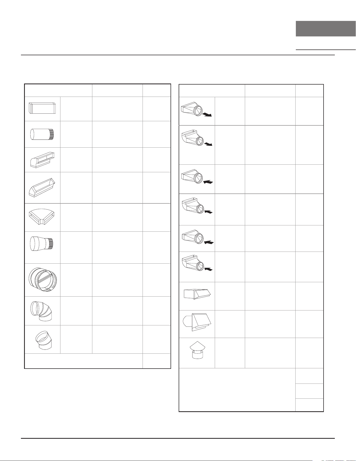
Installation Instructions
Duct pieces
To tal
Equivalent number
length x used =
3- 1/ 4” x 10”
Rect.,
straight
1 Ft. x ( ) =
Ft.
3- 1/ 4” x 10”
Rect. to
6” round
transition
5 Ft. x ( ) =
Ft.
3- 1/ 4” x 10”
Rect. to
6” round
transition
90
0
elbow
20 Ft. x ( ) =
Ft.
6”, 7”, 8”, 10”
Round,
90
0
15 Ft.
x ( ) =
Ft.
6”, 7”, 8”, 10”
Round,
45
0
9 Ft. x ( ) =
Ft.
Ft.
6”, 7”, 8”, 10”
Round,
straight
1 Ft. x ( ) =
Ft.
Subtotal column 1 =
Duct pieces
To tal
Equivalent number
length x used =
6”, 7”, 8”, 10”
Round, wall
cap with
damper
30 Ft. x ( ) =
Ft.
Ft.
Ft.
Ft.
6”, 7”, 8”, 10”
Round
roof cap
30 Ft. x ( ) =
Ft.
Subtotal column 2 =
Subtotal column 1 =
Total ductwork =
Maximum Duct Length: For satisfactory air movement,
the total duct length
should not exceed 150 equivalent feet.
6” round to
3- 1/ 4” x 10”
rect.
transition
1 Ft. x ( ) =
Ft.
6” round to
3- 1/ 4” x 10”
rect.
transition
90
0
elbow
16 Ft. x ( ) =
Ft.
7” round to
3 1/ 4” x 10”
rect.
transition
8 Ft. x ( ) =
Ft.
7” round to
3- 1/ 4” x 10”
rect.
transition
90
0
elbow
23 Ft. x ( ) =
Ft.
elbow
elbow
7” to 6” or
8” to 7” Round
tapered
reducer
25 Ft. x ( ) =
Ft.
3- 1/ 4” x 10”
Rect. 90
0
elbow
15 Ft. x ( ) =
Ft.
3- 1/ 4” x 10”
Rect. 45
0
elbow
9 Ft. x ( ) =
Ft.
3- 1/ 4” x 10”
Rect. 90
0
flat elbow
24 Ft. x ( ) =
Ft.
3- 1/ 4” x 10”
Rect.
wall cap
with damper
30 Ft. x ( ) =
Ft.
Ft. x ( ) =
Ft.
15
6”, 7“, 8”
Round
in-line
damper
Ducting Calculation Sheet
9
Okeanito Use, Care, and Installation Guide
ZEPHYRONLINE.COM
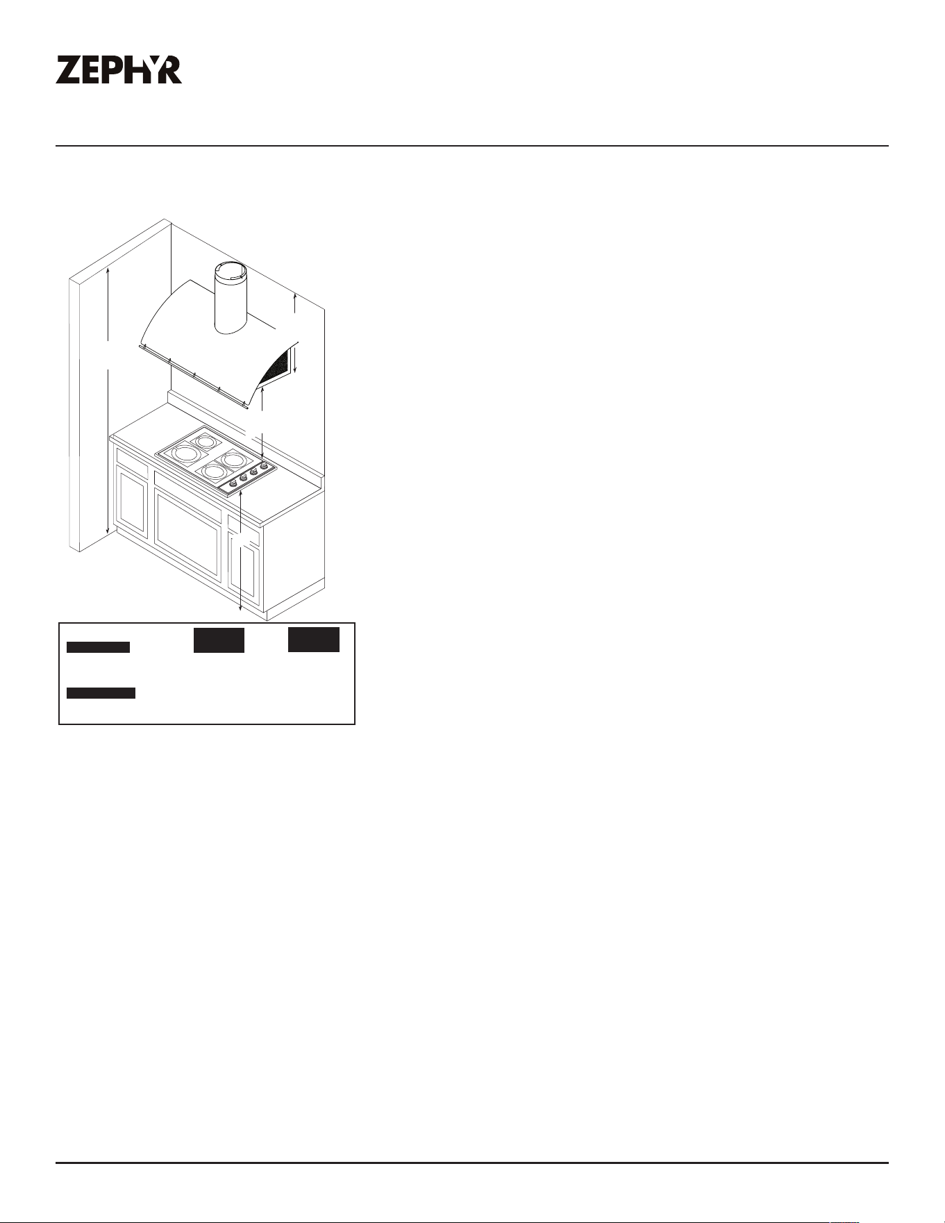
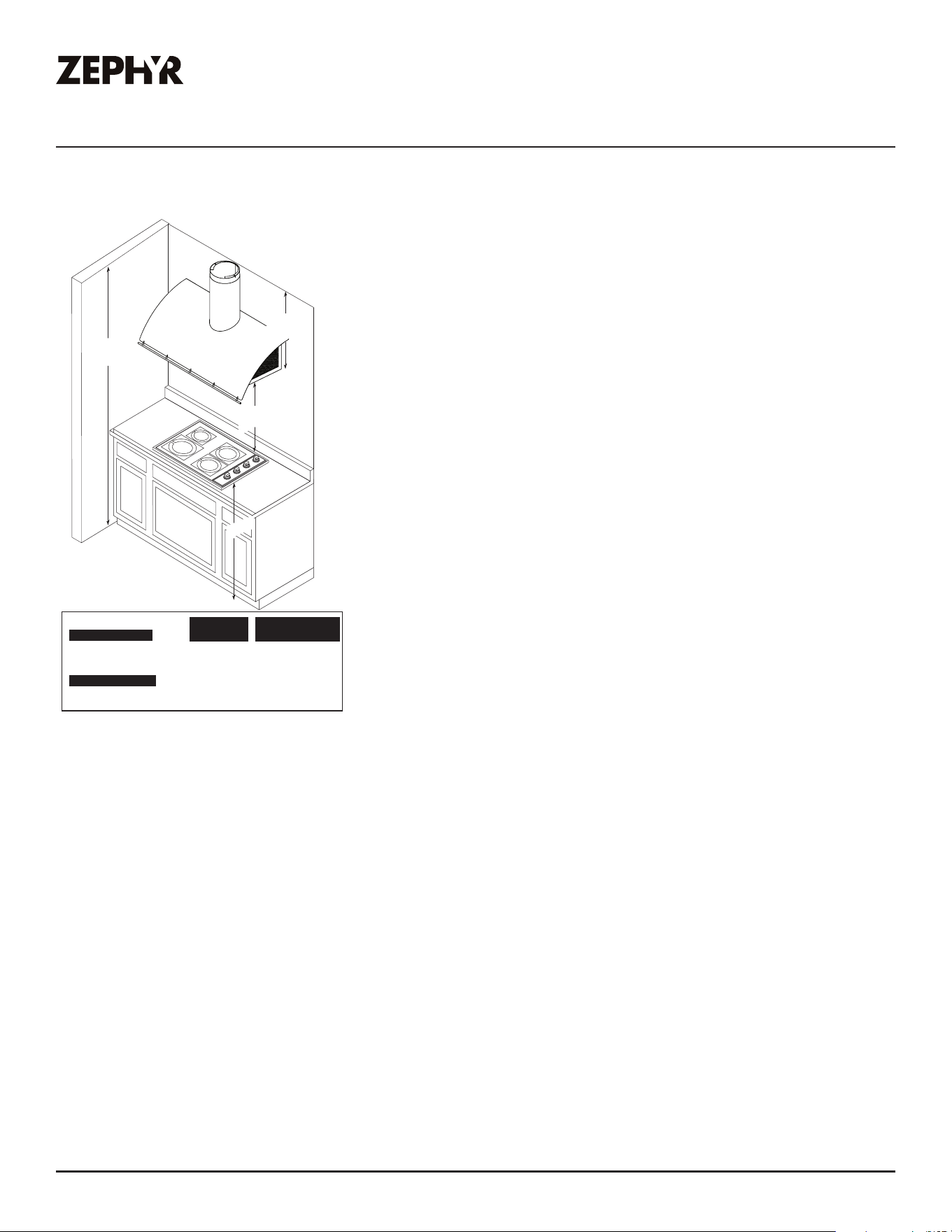
Installation Instructions
Mounting Height, Clearance, & Ducting
A minimum of 6” round duct work must be used to maintain
maximum air flow eciency with the 290/600 CFM internal
blower. A minimum of 8” to 10” round duct work must be used
with the 1000 CFM remote blower.
Always use rigid type metal ducts only. Flexible ducts could
restrict air flow by up to 50%.
Also use calculation (on page 8) to compute total available duct
run when using elbows, transitions and caps.
ALWAYS, when possible, reduce the number or transitions and
turns. If long duct run is required, increase duct size.
If turns or transitions are required; install as far away from insert
duct output and as far apart, between the two as possible.
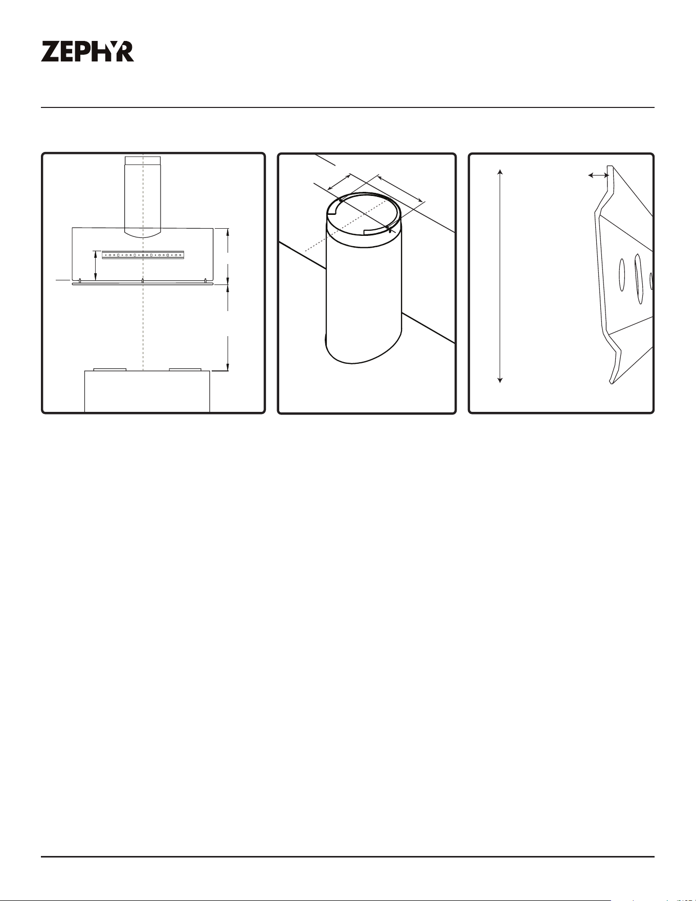
Minimum mount height between range top to insert bottom
should be no less than 24”.
Maximum mount height should be no higher than 36”.
It is important to install the insert at the proper mounting height.
Inserts mounted too low could result in heat damage and fire
hazard; while inserts mounted too high will be hard to reach and
will lose its performance and eciency.
24” min.
36” max.
min. C
max. D
Standard Extension
Hood Heights Duct Cover Duct Cove
r
minimum (A) 30-1/2” 44”
maximum (B) 49-1/2” 77”
Ceiling Heights
minimum (C) 90-1/2” (7’ 6-1/2”) 104” (8’ 8”)
maximum (D) 121-1/2” (10’ 1-1/2”) 149” (12’ 5”)
36”
min. A
max. B
If available, also refer range manufacturer’s height clearance requirements and recommended insert
mounting height above range.
For shipment and installation damages:
► Please fully inspect unit for damage before installation.
► If the unit is damaged in shipment, return the unit to the store in which it was bought for repair or
replacement.
► If the unit is damaged by the customer, repair or replacement is the responsibility of the customer.
► If the unit is damaged by the installer (if other than the customer), repair of replacement must be
made by arrangement between customer and installer.
10
Okeanito Use, Care, and Installation Guide
OKEANITO
WALL
DESIGNER
Installation Instructions
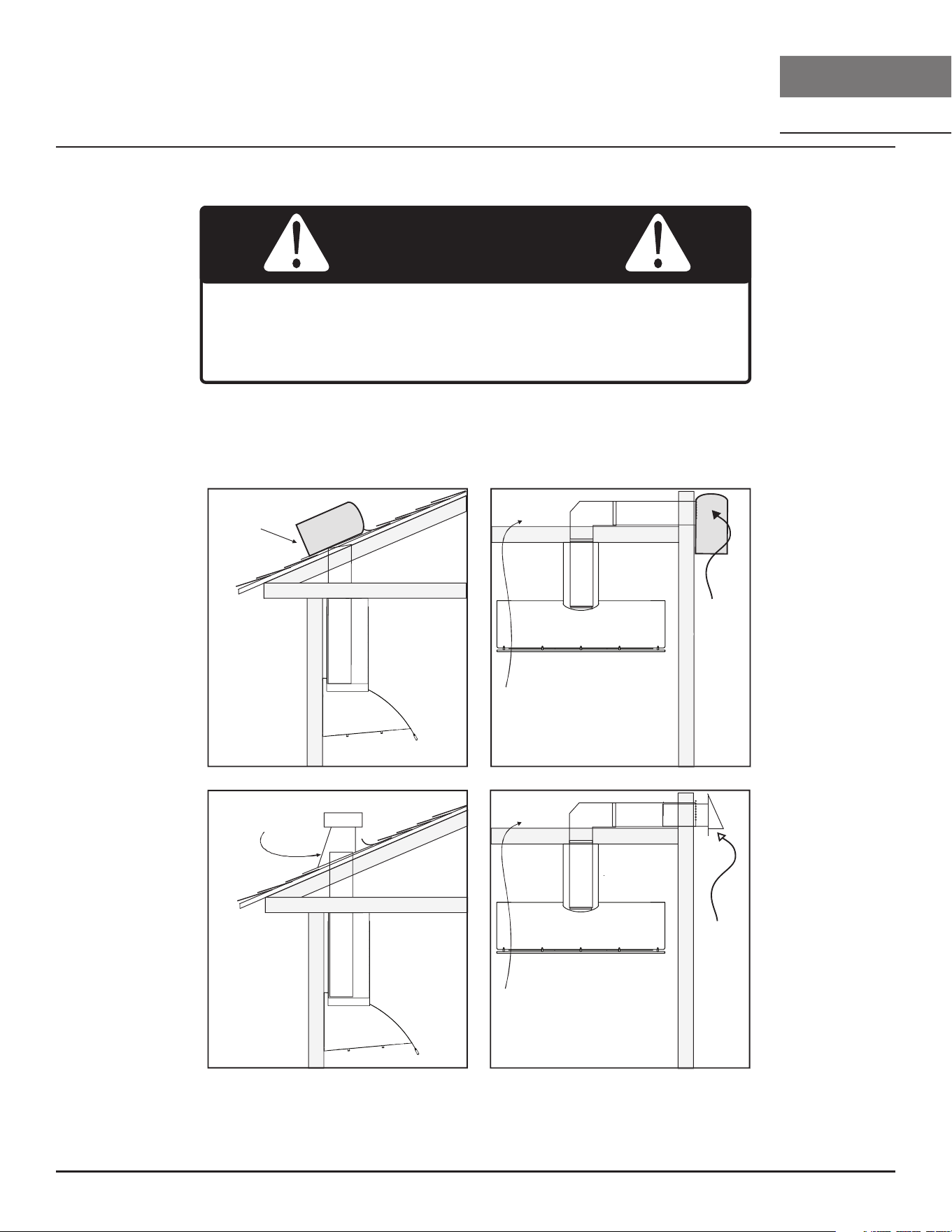
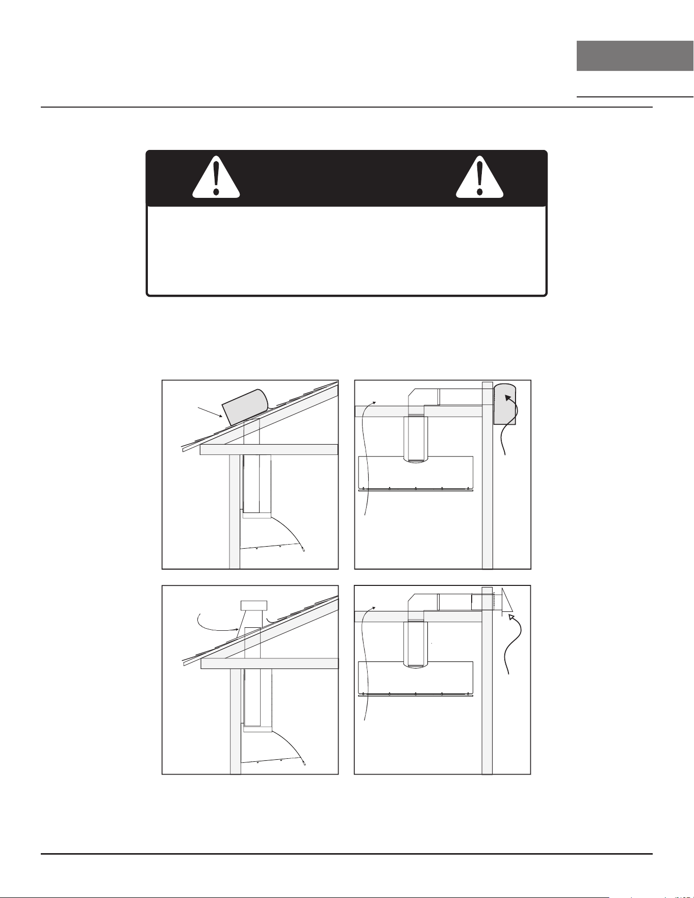
Ducting Options
► Use single wall rigid metal ductwork only.
► Fasten all connections with sheet metal screws and tape all joints w/ certified Silver Tape or Duct
Tape.
Fire Hazard: NEVER exhaust air or terminate ductwork into
spaces between walls, crawl spaces, ceilings, attics, or garages.
All exhaust must be ducted to the outside, unless using the
recirculating option.
WARNING
Side Wall
Cap
External blower
External
blower
Soffit or crawl space
Soffit or crawl space
Roof pitch w/
flashing & cap
11
Okeanito Use, Care, and Installation Guide
ZEPHYRONLINE.COM
Installation Instructions
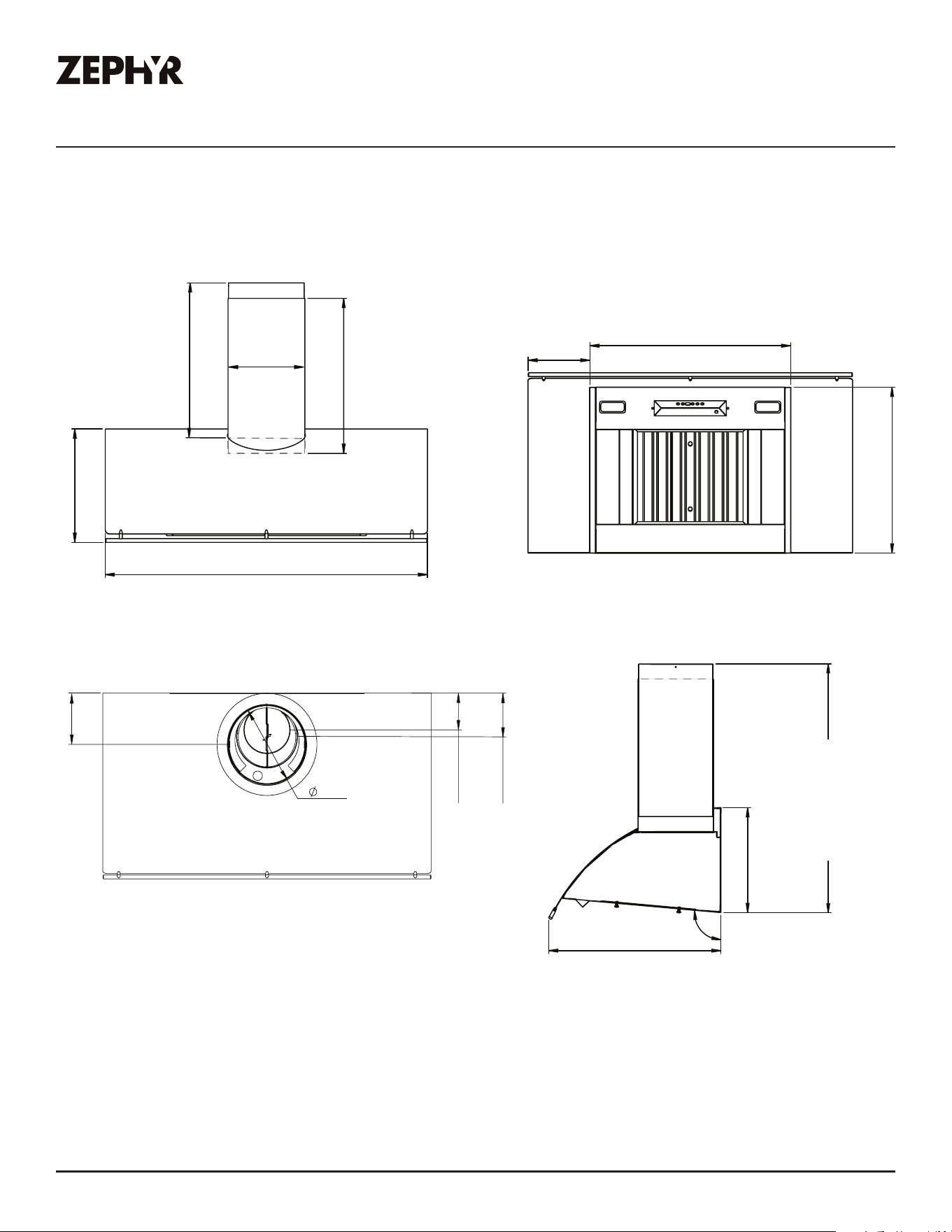
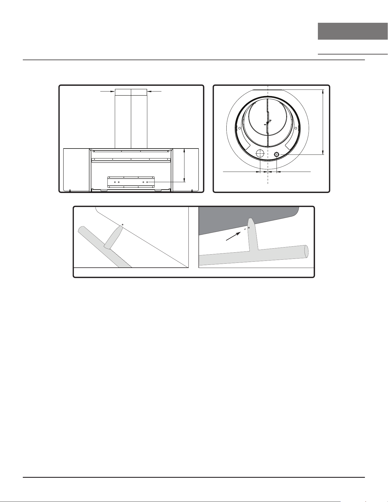
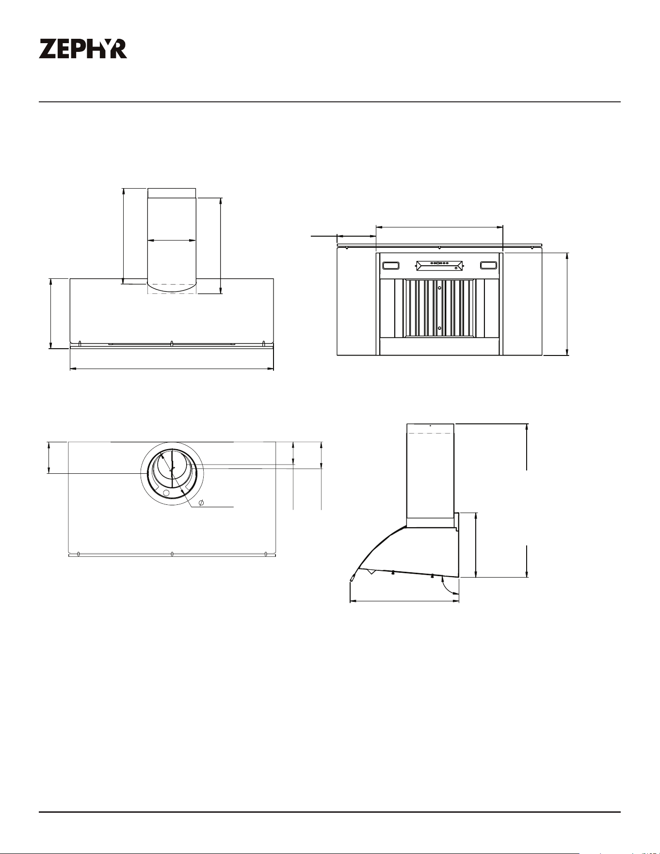
Hood Specications
Front View Bottom View
Top View Side View
95°
22-3/4”
Standard Duct Cover
min. : 30-1/2”
max. : 49-1/2”
Z1C-00OK Extension
min. : 44”
max. : 77”
6”
10”
5-1/8”
4-1/4”
(36”) 26-1/16”
(42“) 26-1/16”
(48“) 41”
21”
(36”) 5”
(42“) 8”
(48“) 3-1/2”
duct cover
C/L
6” collar C/L
8” collar C/L
19-3/4”
19-3/4”
14-1/2”
36”, 42”, 48”
10”
13-1/2”
12
Okeanito Use, Care, and Installation Guide
OKEANITO
WALL
DESIGNER
Installation Instructions
Electrical Supply
Electrical wiring must be done by qualified person(s) in
accordance with all applicable codes and standards. Turn o
electrical power at service entrance before wiring.
WARNING
For personal safety, remove house fuse or open circuit breaker before beginning installation. Do not
use extension cord or adapter plug with this appliance.
Follow national electrical codes or prevailing local codes and ordinances.
This appliance requires a 120V 60Hz electrical supply, and connected to an individual, properly
grounded branch circuit, protected by a 15 or 20 ampere circuit breaker or time delay fuse. Wiring
must be 2 wire w/ ground. Please also refer to the Electrical Diagram labeled on product.
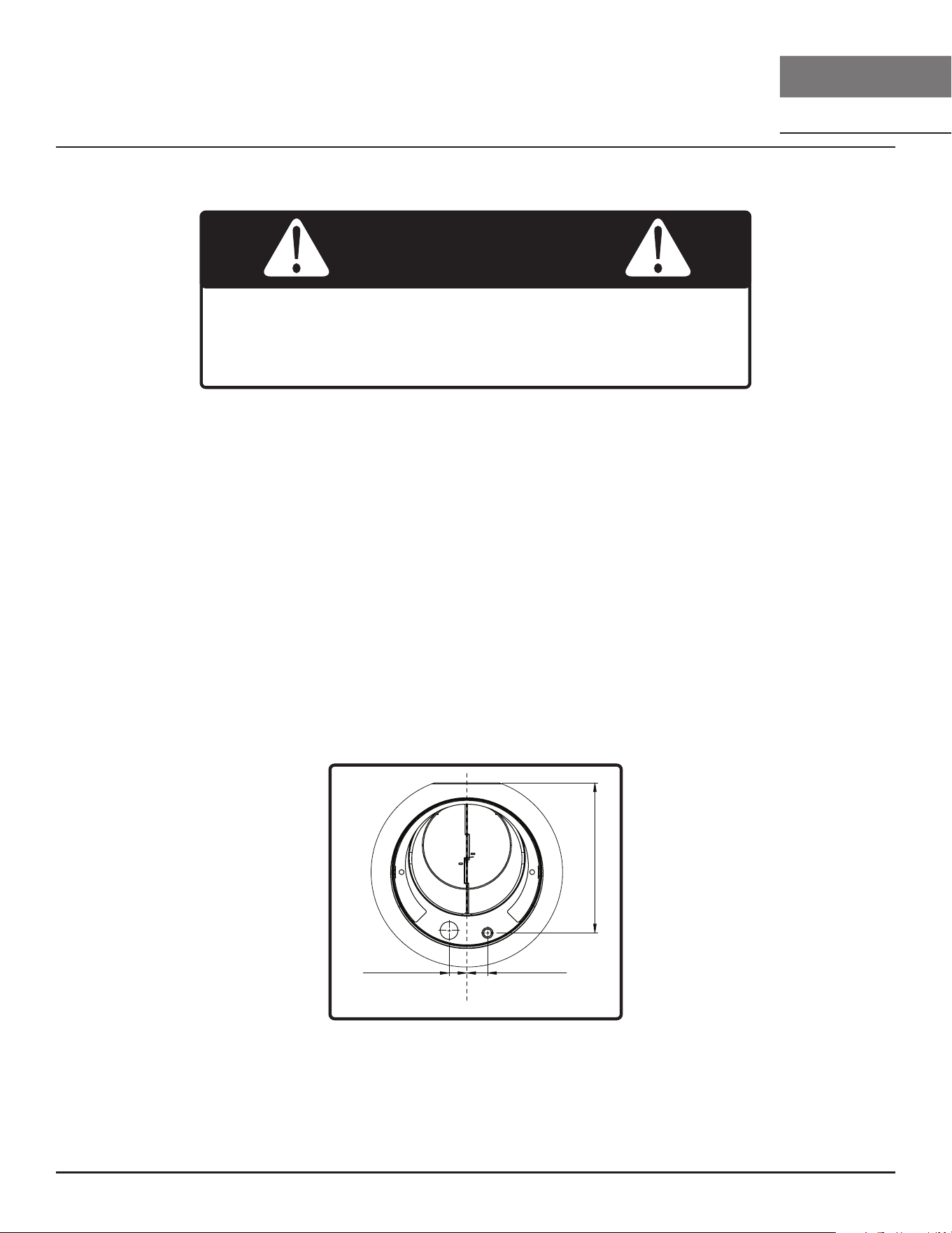
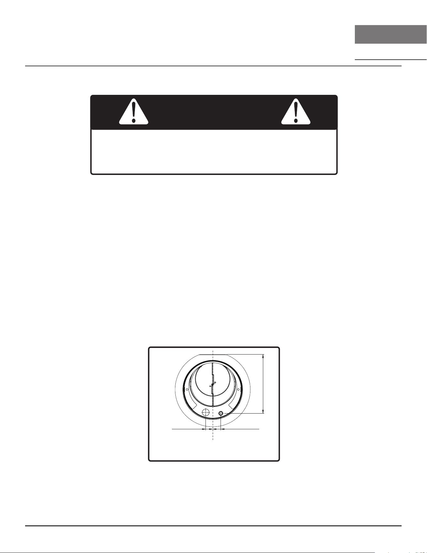
Cable Lock
A cable locking connector (not supplied) might be required by local codes. Check with local
requirements and codes, purchase and install appropriate connector if necessary. (FIG. A)
remote blower
knockout
electrical
knockout
7/8”
1-7/8”
9-15/16”
C/L
FIG. A
13
Okeanito Use, Care, and Installation Guide
ZEPHYRONLINE.COM
Installation Instructions
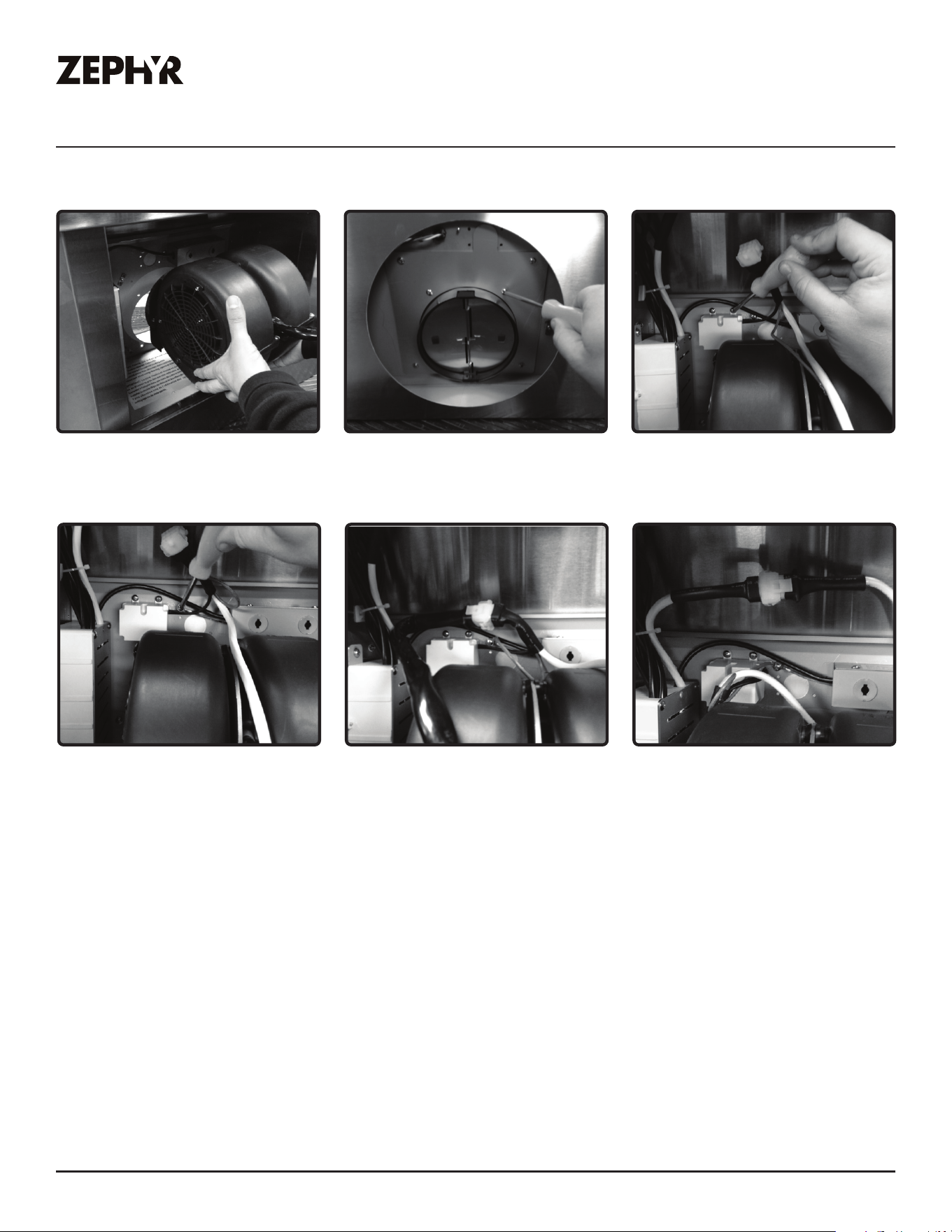
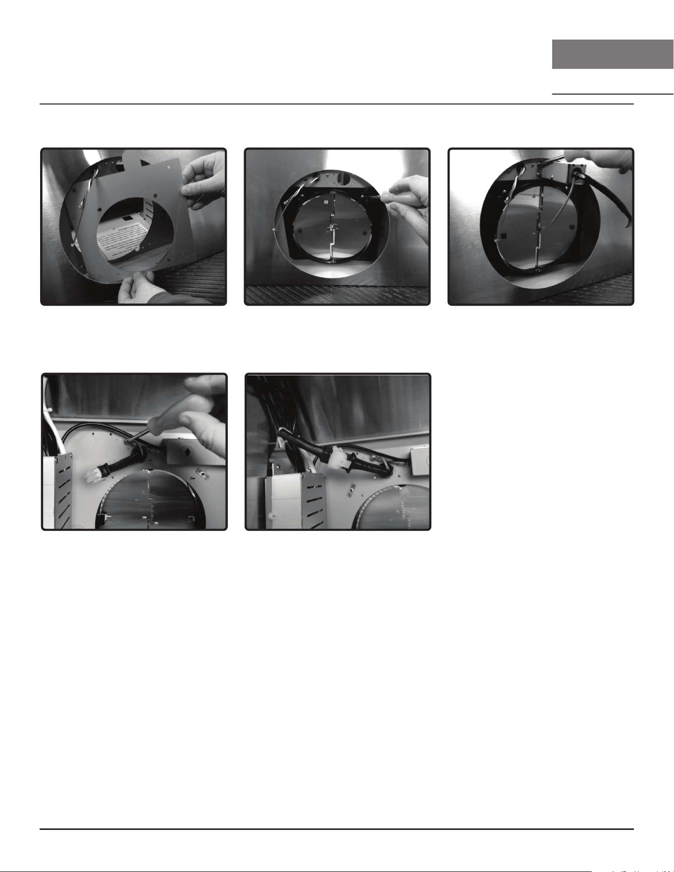
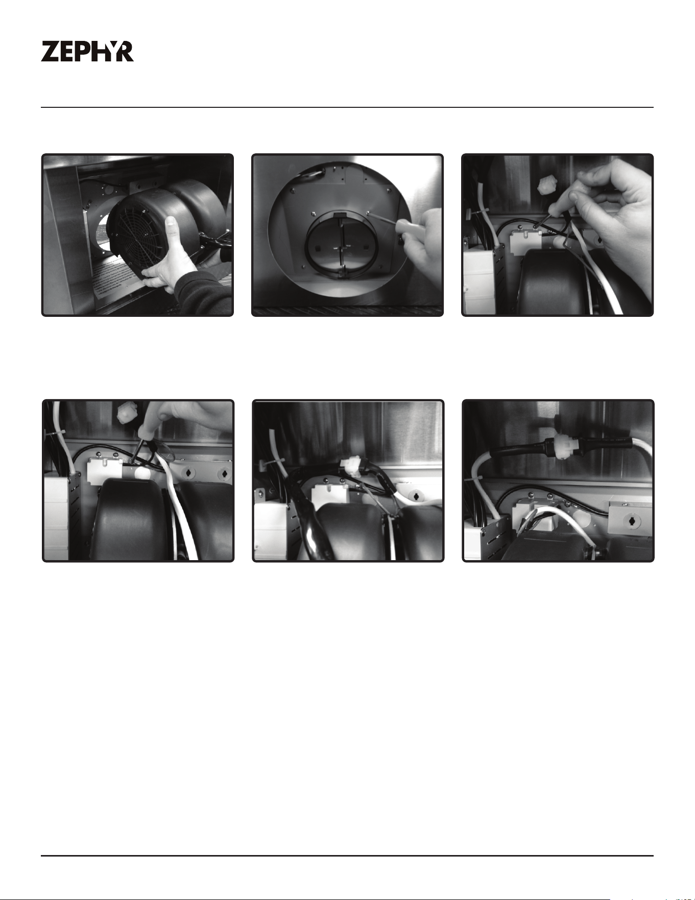
Internal Blower Preparation
2. Secure internal blower to internal
blower flange by (4) M4*16 screws
from internal blower hardware.
1. Position internal blower inside
hood body so internal blower
collar protrudes through 6” round
flange opening.
3. Position capacitor box inside
hood body and secure by (2)
M4*8 screws from internal blower
hardware.
5. Connect 9 pin molex connector
from internal motor to 9 pin molex
connector from capacitor cable
box. Secure cable to hood interior
with zip tie and zip tie holder.
4. Secure ground wire from
capacitor box to ground wire rivet
nut next to capacitor box.
6. Connect 6 pin molex connector
from control board to 6 pin molex
connector from capacitor box
cable. Secure cable to hood
interior with zip tie and zip tie
holder.
14
Okeanito Use, Care, and Installation Guide
OKEANITO
WALL
DESIGNER
Installation Instructions
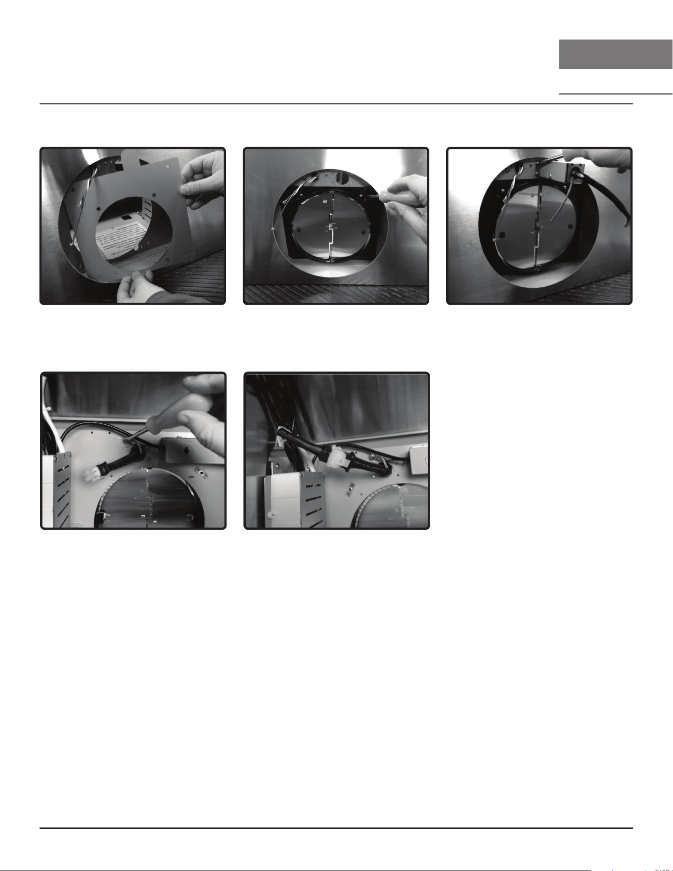
Remote Blower Preparation
2. Install remote blower 8” round
collar. Attach by (4) M4*8 screws.
1. Remove internal blower flange
from motor housing by (6) screws.
3. Install threaded cable lock and
remote blower wiring harness
through the remote blower wiring
knockout. Attach by (4) M4*8
screws.
5. Connect 6 pin male connector
from remote blower wiring to 6
pin female connector on control
board box.
4. Secure ground wire from remote
blower wiring to ground wire rivet
nut.
NOTE: For instructions on mounting
the remote blower, please refer to
the CBE-1000 or PBN-1000A remote
blower manual included in the remote
blower packaging or on our website at
www.zephyronline.com

15
Okeanito Use, Care, and Installation Guide
ZEPHYRONLINE.COM
Installation Instructions
Mounting the Range Hood
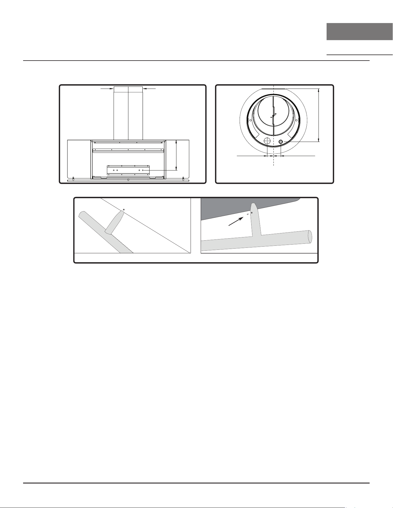
1. Measure from cooking surface to desired hood bottom, level and mark line A. (26” minimum from
cooking surface)
2. Plum and mark center line.
3. Mark line B, 9-11/16” up from line A. This is the top position of the wall bracket. FIG. B.
4. Follow center line up to the ceiling, measure and mark ceiling bracket mount line C, 6” out from
the wall onto the ceiling. FIG. C.
5. Mark ceiling bracket mounting spread, 8-11/16” from center line on line C. FIG. C.
6. Place duct cover ceiling bracket onto ceiling and mark inside diameter of ceiling bracket. Cut
inside diameter of ceiling bracket to fit the 6” or 8” round duct pipe.
7. Prepare duct work and electrical through ceiling.
8. Attach ceiling bracket to ceiling by (2) M4 * 38 screws. Wood blocking may need to be added
inside ceiling to support the weight of the upper duct cover.
9. Place and center the top of wall bracket on line B, FIG. B. The top of the wall bracket will have a
gap between the bracket and the wall. FIG. D.
A
min. 26”
max. 36”
C/L
14-1/2”
9-11/16”
B
C/L
6”
C/L
8-11/16”
C
FIG. B FIG. C
Top
Bottom
gap between
bracket and
wall
FIG. D
16
Okeanito Use, Care, and Installation Guide
OKEANITO
WALL
DESIGNER
Installation Instructions
Mounting the Range Hood
remote blower
knockout
electrical
knockout
7/8”
1-7/8”
9-15/16”
C/L
FIG. E FIG. F
10-9/16”
Upper duct cover
attachment screw
locations
Back View
10. Attach wall bracket to wall by (3) M4*38 screws with washers. NOTE: Wood blocking may need to
be added behind the drywall if no studs are present. Wall anchors may also be used but check
with local codes for compliance. Failure to use suitable wall anchors and screws to hold the weight
of the hood could result in personal injury or damage to the cooking surface or counter.
11. Lift hood onto wall bracket. The lip at the back of the hood body will rest between the wall and the
top lip of the wall bracket. Secure hood body in place by (2) M4*38 screws though bottom section
of interior of hood body. FIG. E.
12. Place telescopic duct covers on top of hood.
13. Run duct work from ceiling to motor collar and seal all joints with certified aluminum duct tape
and install electrical wiring. FIG. F.
14. Attach upper (inner) duct cover to ceiling bracket by (2) M4*8 screws. FIG. E.
15. Attach utensil rail to hood canopy by (3) set screws (pre-installed into rail) using the provided Allen
key. FIG. G. A small hole has been pre-drilled into the canopy to provide a starting point to attach
the first utensil rail post. After the first post is lined up with the hole, gently slide the rest of the rail
onto the canopy. Be careful not to scratch the stainless of the canopy while installing the utensil
rail.
Front Back
Set screw
FIG. G
17
Okeanito Use, Care, and Installation Guide
ZEPHYRONLINE.COM
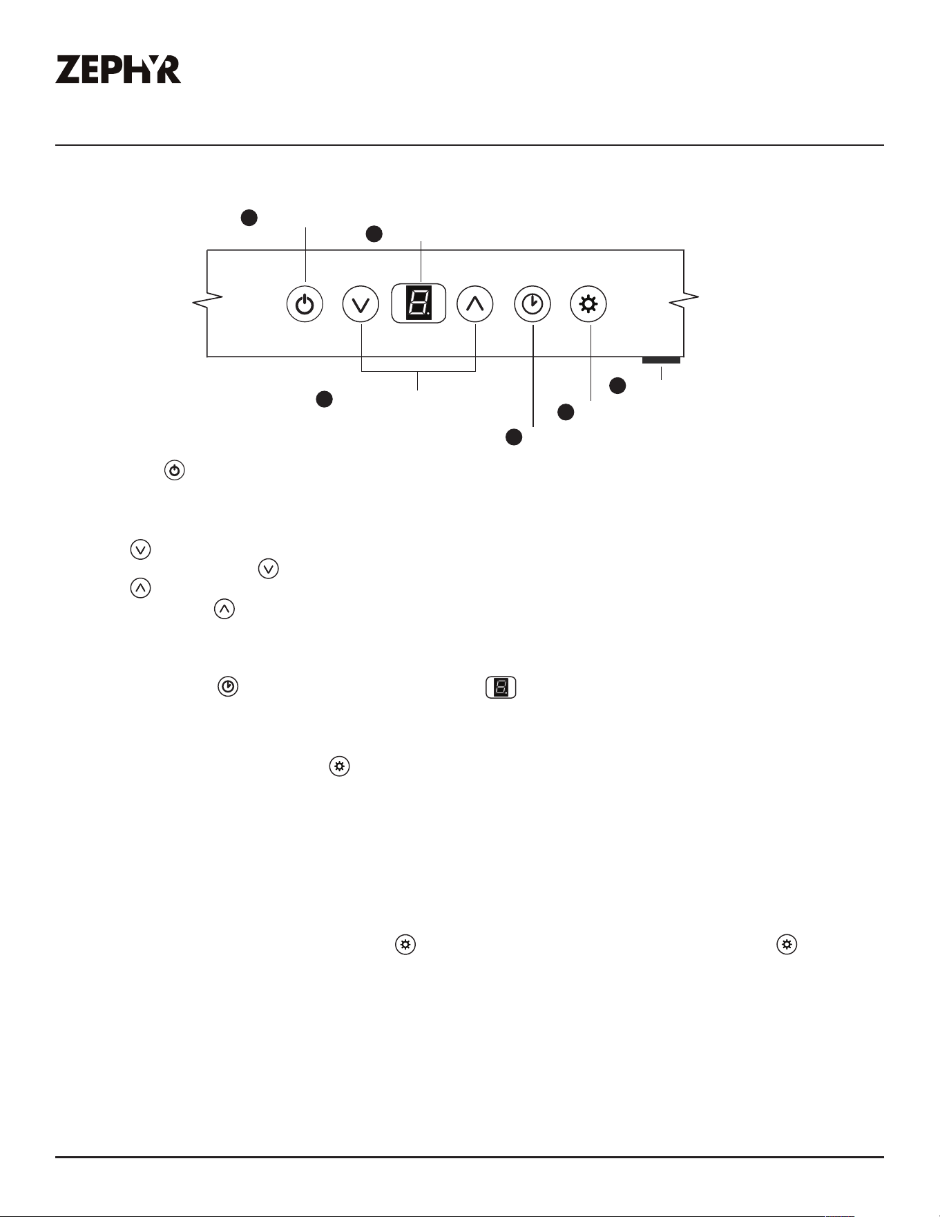
Features & Controls
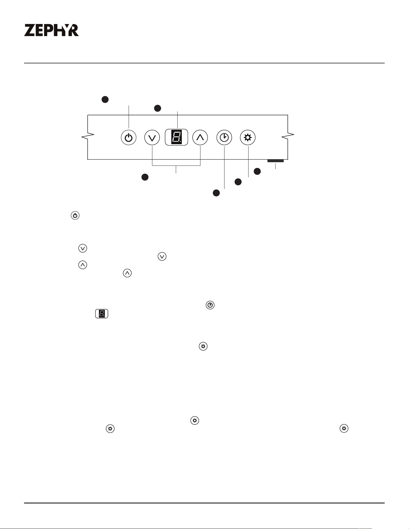
1. Bl
ower On/Off
By pr
essing the blower is switched on and off. When switched on, the blower starts up on speed level 1.
2. Speed Selection
- Pr
ess to decrease fan speed. 3, 2, 1.
- If fan is on Speed 1 and is pr
essed, the fan will power off.
- Pr
ess to increase fan speed. Fan On, 1, 2, 3.
- If hood is off and is pr
essed, the fan will turn on speed 1.
3
. Delay Off
This featur
e is used for programmed shut down of blower 5 minutes after the function is activated. Press
once
, a dot flashes in the lower right side of display indicating the function is on. The blower will
completely shut do
wn after 5 minutes.
4
. Lights Low/Medium/High/Off
Switch ligh
ts on to low by pressing once, press a second time for medium, press a third time for high,
and pr
ess again to shut off the lights.
5
. Display Window
The display windo
w indicates speed levels and features such as baffle filter clean reminder, delay off and
clean air indicator
.
6
. Mood Light On/Off
This is the mas
ter on and off button for the mood lights. Press in to turn on, press again to turn off. When
the mas
ter mood light switch is on, pressing will power off the LED and mood lights. Pressing again
will turn the LED and mood ligh
ts back on.
Lights Low/Medium/High/Off
5 Min Delay Off
Display (speed level, delay off, filter clean)
Adjust 3 Speed Levels
Blower On/Off
1
2
3
4
5
Mood Light On/Off
6
Touch Controls
18
Okeanito Use, Care, and Installation Guide
OKEANITO
WALL
DESIGNER
Features & Controls
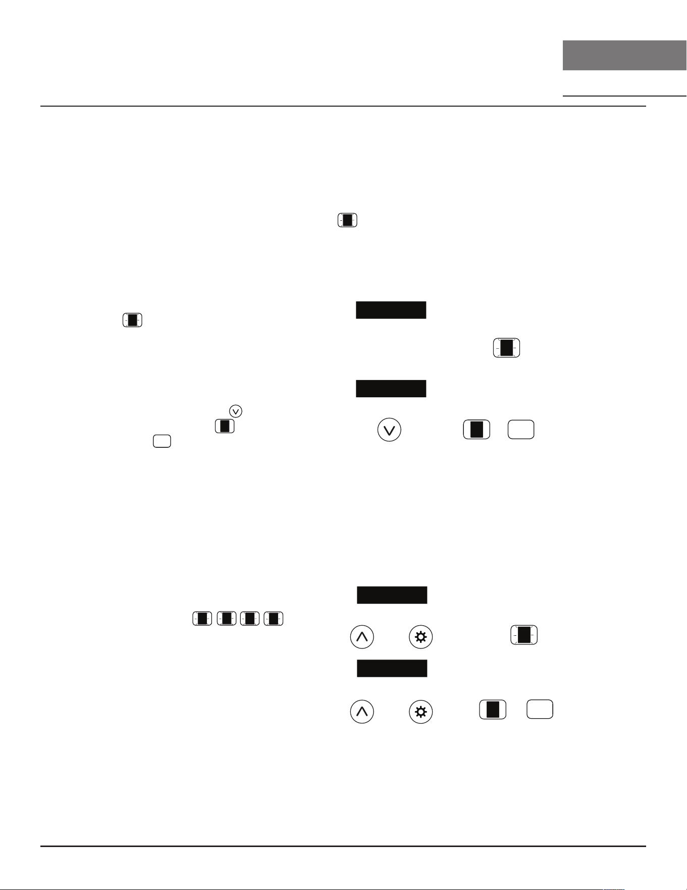
Touch Controls
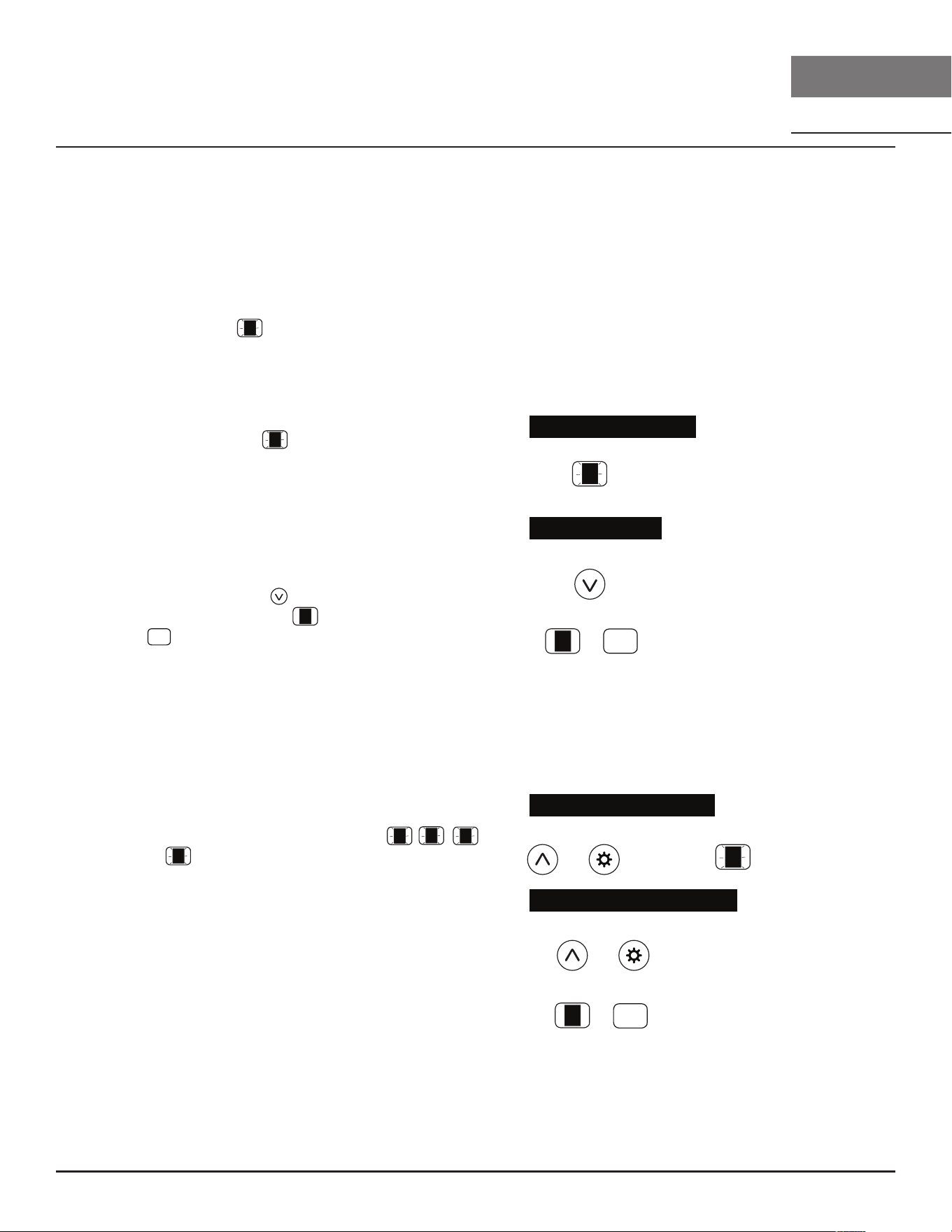
Baffle Filter Clean Reminder
A set of baffle filters are fitted by the factory, these baffle filters are intended to filter
out residue from cooking. The filters need not be replaced on a regular basis but are
required to be kept clean. The Baffle Filter Clean reminder function in the microproces-
sor will automatically indicate by a flashing when the baffle filters need to be
cleaned after every 60 hours of use. Filters can be cleaned by hand with non-abrasive
soap or in a dishwasher. Heavily soiled filters should also be soaked in grease cutting
detergent prior to cleaning.
Baffle Filter Clean Indicator
When flashes on the display, the baffle
filters needo be cleaned. This will occur
after every 60 hours of use.
Reset the filter clean reminder timer after
filters are cleaned and re-installed. With
hood off, press and hold for approxi-
mately 5 seconds until on display
disappears . The filter clean reminder
function is now reset and a new 60 hours
elapse cycle is initiated.
Clean Filters
display < F > flashes
hold 5 sec. display from < F > to < >
To Reset
hold 3 sec. display fr
om < A > to < >
To Disable
hold 3 sec.
To Enable
display < A > flashes
Clean Air Indicator
While Clean Air is activ
e, the display will
alternate betw
een , , , .
Af
ter 10 minutes of Clean Air operation, the
blo
wer will power off and the 4 hour timer
will r
eset.
If the blo
wer speed is changed while the
Clean Air Function is in use
, the cycle will be
in
terrupted and the timer will reset after.
Clean Air Function
Clean Air is a featur
e that turns on the blower on low speed every 4 hours for 10 minutes
to r
emove stagnant air in the kitchen. The Clean Air function is disabled by default and
mus
t be enabled by the user.
and
and
F
F
F
F
F
F
A
A
A
A
A
A
1
1
1
1
A
A
F
F
F
F

19
Okeanito Use, Care, and Installation Guide
ZEPHYRONLINE.COM
Hood & Grease Filter Cleaning
Surface Maintenance
► Do not use corrosive detergents, abrasive detergents or oven cleaners.
► Do not use any product containing chlorine bleach or any product containing chloride.
► Do not use steel wool or abrasive scrubbing pads which will scratch and damage surface.
Cleaning Stainless Steel
Clean periodically with warm soapy water and clean cotton cloth or micro fiber cloth. Always rub
in the direction of the stainless steel grain. To remove heavier grease build up use a liquid degreaser
detergent.
After cleaning use a non-abrasive stainless steel polish/cleaners, to polish and bu out the stainless
luster and grain. Always scrub lightly, with clean cotton cloth or micro fiber cloth and bu in the
direction of the stainless steel grain.
Cleaning the Grease Filter
The grease filter installed by the factory are intended to filter out residue and grease from cooking.
They need not be replaced on a regular basis but are required to be kept clean.
Remove and clean by hand or in dishwasher using a non-phosphate detergent. Discoloration of
the grease filter may occur if using phosphate detergents, or as a result of local water conditions -
but this will not aect filter performance. This discoloration is not covered by the warranty. Spray
degreasing detergent and leave to soak if heavily soiled.
Dry grease filter and re-install before using hood.
Maintenance
20
Okeanito Use, Care, and Installation Guide
OKEANITO
WALL
DESIGNER
Maintenance
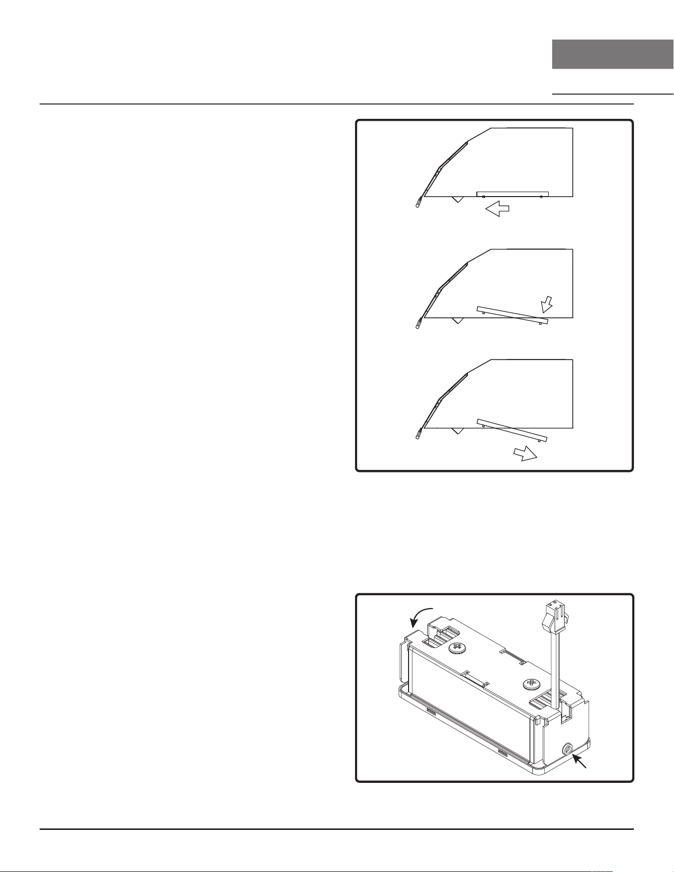
Removing the Grease Filter (FIG. H)
1. Pull filter towards front of the range hood using
handles.
2. Pivot the back of the filter downward.
3. Push filter to the rear and remove.
1
2
3
FIG. H
Swivel LumiLight LED
In the unlikely event that your swivel LumiLight LED fails, please contact Zephyr to order replacement
parts. See the list of parts and accessories page for part numbers and contact information.
LED Removal (FIG. I)
1. Remove grease filters.
2. (If applicable) remove both side spacer panels
for each spacer panel.
3. Remove screws on light panel.
4. Disconnect LED light quick connector.
5. Remove (2) screws from the sides per LED light.
6. Push LED light through the light panel opening.
FIG. I

21
Okeanito Use, Care, and Installation Guide
ZEPHYRONLINE.COM
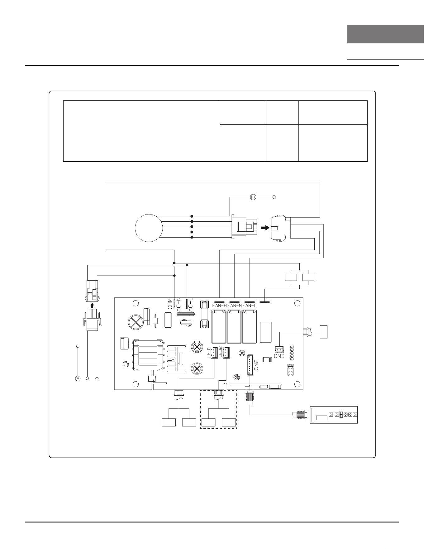
Wiring Diagram
COK-E36/42/48CSX
INTERNAL BLOWER CIRCUIT DIAGRAM
VOLTS
120
HZ
60
MAX AMPS
CBI-290C 0.8
CBI-390A 2.1
CBI-600A 2.6
REMARKS: CONDENSER 3 uF 250V AC120V 60Hz (CBI-290C)
CONDENSER 25uF 250V AC120V 60Hz (CBI-390A/CBI-600A)
WHITE
YELLOW
RED
BLUE
GREEN
BLACK
WHITE
BODY
BLACK
WHITE
BLACK
WHITE
BLUE
RED
YELLOW
Control PC
LED LED LED LED
for 48” only
MOTOR
BODY
GREY
BLACK
BLACK
WHITE
WHITE
BLACK
LL
B/W
SW
WHITE
COK-E36/42/48CBGX
22
Okeanito Use, Care, and Installation Guide
OKEANITO
WALL
DESIGNER
Wiring Diagram
REMOTE BLOWER CIRCUIT DIAGRAM
VOLTS
120
HZ
60
MAX AMPS
WHITE
YELLOW
RED
BLUE
GREEN
BLACK
WHITE
BODY
BLACK
WHITE
BLACK
WHITE
BLUE
RED
YELLOW
Control PC
LED LED LED LED
for 48” only
BLACK
WHITE
WHITE
BLACK
LL
B/W
SW
WHITE
CBE-1000 6.2
PBN-1000A 5.1
REMARKS: CONDENSER 15 uF 370V AC120V 60Hz (CBE-1000)
CONDENSER*2 25uF 250V AC120V 60Hz (PBN-1000A)
GREEN
WHITE
BLACK
BLUE
RED
BODY
MOTOR
COK-E36/42/48CSX
COK-E36/42/48CBGX
23
Okeanito Use, Care, and Installation Guide
ZEPHYRONLINE.COM
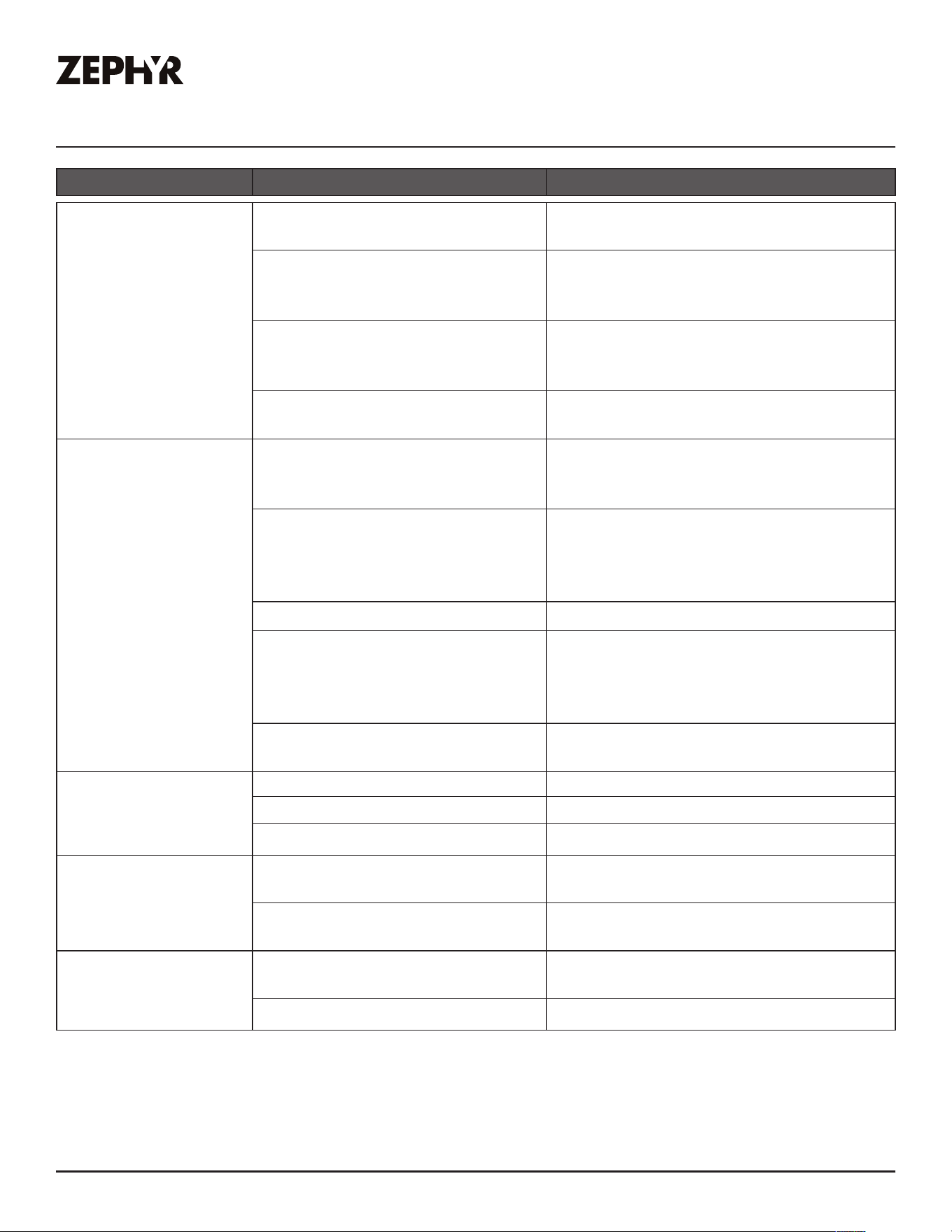
Troubleshooting
Possible Problem Possible Cause Solutions
After installation, the
unit doesn’t work.
The power source is not turned
ON.
Make sure the circuit breaker and the
unit’s power is ON.
The power line and the cable
locking connector is not
connecting properly.
Check the power connection with the
unit is connected properly.
The switch board and control
board wirings are disconnected.
Make sure the wirings between the
switch board and control board are
connected properly.
The switch board or control board
is defective.
Change the switch board or control
board.
Light works, but
blower is not turning.
Wire harness from external
or internal blower might be
disconnected.
Make sure the wires are connected to
the control board box.
The thermally protected system
detects if the blower is too hot
to operate and shuts the blower
down.
The blower will function properly after
the thermally protected system cool
down.
Damaged capacitor. Change the capacitor.
Blower molex plug pin is not
making contact.
Disconnect the blower molex plug, check
pins inside plug to see if pin is pushed
inside the plug too far. Reset pin if
needed.
The blower is defective, possibly
seized.
Change the blower.
The unit is vibrating. The blower is not secured in place. Tighten the blower in place.
Damaged blower wheel. Replace the blower.
The hood is not secured in place. Check the installation of the hood.
The unit is whistling. A filter is not in the correct
position.
Adjust the filters until the whistling stops.
The duct pipe connections are not
sealed or connected properly.
Check the duct pipe connections to be
sure all connections are sealed properly.
The blower is working,
but the lights are not.
The LED light connector is
disconnected.
Connect the LED light connector.
Defective LED light. Change the LED light.

24
Okeanito Use, Care, and Installation Guide
OKEANITO
WALL
DESIGNER
Troubleshooting
The hood is not
venting out properly.
Using the wrong size of ducting. Change the ducting to at least 6” or
higher for the internal blower and 8” or
higher for the external blower.
The hood might be hanging to
high from the cook top.
Adjust the distance between the cooktop
and the bottom of the hood within 24”
and 36” range.
The wind from the opened
windows or opened doors in the
surrounding area are aecting
the ventilation of the hood.
Close all the windows and doors to
eliminate the outside wind flow.
Blockage in the duct opening or
ductwork.
Remove all the blocking from the duct
work or duct opening.
There are too many turns within
the ducting.
Limit number of turns and/or increase
duct size.
Filter is vibrating. Filter is loose. Adjust or change the filter.
Possible Problem Possible Cause Solutions
25
Okeanito Use, Care, and Installation Guide
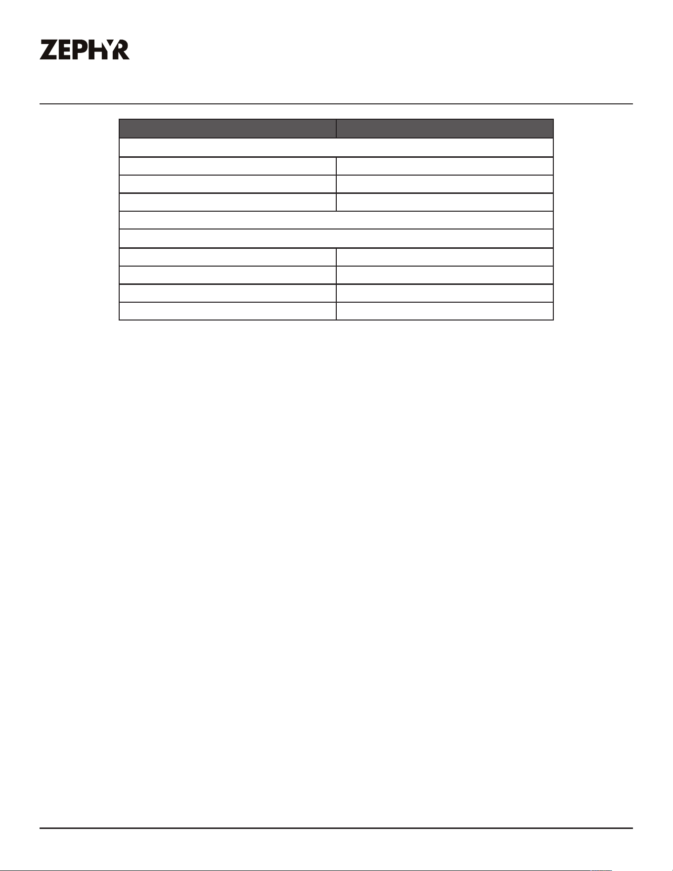
ZEPHYRONLINE.COM
List of Parts & Accessories
Description Part Number
Replacement Parts
Bae Filter (each) 50210036
LED Bulb, 4W P12010008
Swivel LumiLight LED, 6W Z0B0052
Optional Accessories
Duct Cover Extension Z1C-00OK
Single Internal Blower CBI-290C / CBI-600A
External Blower CBE-1000
In-line Blower PBN-1000A
To order parts, visit us online at http://store.zephyronline.com.

26
Okeanito Use, Care, and Installation Guide
OKEANITO
WALL
DESIGNER
Notes

27
Okeanito Use, Care, and Installation Guide
ZEPHYRONLINE.COM
Limited Warranty
Zephyr Ventilation, LLC (referred to herein as “we” or “us”) warrants to the original consumer purchaser (referred to herein
as “you” or “your”) of Zephyr products (the “Products”) that such Products will be free from defects in materials or
workmanship as follows:
Three Year Limited Warranty for Parts: For three years from the date of your original purchase of the Products, we will
provide, free of charge, Products or parts (including LED light bulbs, if applicable) to replace those that failed due to
manufacturing defects subject to the exclusions and limitations below. We may choose, in our sole discretion, to repair or
replace parts before we elect to replace the Products.
One Year Limited Warranty for Labor: For one
y
ear from the date of your original purchase of the Products, we will
provide, free of charge, the labor cost associated with repairing the Products or parts to replace those that failed due to
manufacturing defects subject to the exclusions and limitations below. After the first year from the date of your original
purchase, you are responsible for all labor costs associated with this warranty.
Warranty Exclusions: This warranty covers only repair or replacement, at our option, of defective Products or parts and
does not cover any other costs related to the Products including but not limited to: (a) normal maintenance and service
required for the Products and consumable parts such as fluorescent, incandescent or halogen light bulbs, mesh and char-
coal filters and fuses; (b) any Products or
parts which have been subject to freight damage, misuse, negligence, accident,
faulty installation or installation contrary to recommended installation instructions, improper maintenance or repair (other
than by us); (c) commercial or government use of the Products or use otherwise inconsistent with its intended purpose; (d)
natural wear of the finish of the Products or wear caused by improper maintenance, use of corrosive and abrasive cleaning
products, pads, and oven cleaner products; (e) chips, dents or cracks caused by abuse or misuse of the Products; (f) service
trips to your home to teach you how to use the Products; (g) damage to the Products caused by accident, fire, floods, acts
of God; or (h) Custom installations or alterations that impact serviceability of the Products. If you are outside our service
area, additional charges may apply for shipping costs for
warranty repair at our designated service locations and for the
travel cost to have a service technician come to your home to repair, remove or reinstall the Products. After the first year
from the date of your original purchase, you are also responsible for all labor costs associated with this warranty. All Products
must be installed by a qualified professional installer to be eligible for warranty repairs or service.
Limitations of Warranty. OUR OBLIGATION TO REPAIR OR REPLACE, AT OUR OPTION, SHALL BE YOUR SOLE
AND EXCLUSIVE REMEDY UNDER THIS WARRANTY. WE SHALL NOT BE LIABLE FOR INCIDENTAL,
CONSEQUENTIAL OR SPECIAL DAMAGES ARISING OUT OF OR IN CONNECTION WITH THE USE OR
PERFORMANCE OF THE PRODUCTS. THE EXPRESS WARRANTIES IN THE PRECEDING SECTION ARE
EXCLUSIVE AND IN LIEU OF ALL OTHER EXPRE
SS
WARRANTIES. WE HEREBY DISCLAIM AND EXCLUDE ALL
OTHER EXPRESS WARRANTIES FOR THE PRODUCTS, AND DISCLAIM AND EXCLUDE ALL WARRANTIES
IMPLIED BY LAW, INCLUDING THOSE OF MERCHANTABILITY AND FITNESS FOR A PARTICULAR PURPOSE.
Some states or provinces do not allow limitations on the duration of an implied warranty or the exclusion or limitation of
incidental or consequential damages, so the above limitations or exclusions may not apply to you. To the extent that
applicable law prohibits the exclusion of implied warranties, the duration of any applicable implied warranty is limited to the
same three-year and one-year periods described above if permitted by applicable law. Any oral or written description of the
Products is for the sole purpose of identifying the Products and shall not be construed as an express warr
a
nty. Prior to
using, implementing or permitting use of the Products, you shall determine the suitability of the Products for the intended
use, and you shall assume all risk and liability whatsoever in connection with such determination. We reserve the right to
use functionally equivalent refurbished or reconditioned parts or Products as warranty replacements or as part of warranty
service. This warranty is not transferable from the original purchaser and only applies to the consumer residence where the
Product was originally installed located in the United States and Canada. This warranty is not extended to resellers.
To Obtain Service Under Limited Warranty: To qualify for warranty service, you must: (a) notify us at the address or
telephone number stated below within 60 days of the discovery of the defect; (b) give the model number and serial
number;
and (c) describe the nature of any defect in the Product or part. At the time of the request for warranty service, you must
present evidence of your proof of purchase and proof of the original purchase date. If we determine that the warranty
exclusions listed above apply or if you fail to provide the necessary documentation to obtain service, you will be responsible
for all shipping, travel, labor and other costs related to the services. This warranty is not extended or restarted upon warranty
repair or replacements.
Please check our website for any additional Product information,
www.zephyronline.com
Zephyr, 2277 Harbor Bay Parkway, Alameda, CA 94502
TO OBTAIN SERVICE UNDER WARRANTY OR FOR ANY SERVICE RELATED QUESTIONS
United States Customers please call: 1-888-880-8368 or contact us at: zephyronline.com/contact
Canada Customers please call: 1-800-361-0799 or Email: [email protected]
Limited Warranty
28
Okeanito Use, Care, and Installation Guide
OKEANITO
WALL
DESIGNER
Product Registration
Congratulations on the purchase of your
Zephyr product! Please take a moment to
register your new Zephyr product at
www.zephyronline.com/registration
Zephyr Ventilation | 2277 Harbor Bay Pkwy. | Alameda, CA 94502 | 1.888.880.8368
Prompt registration helps in more ways
than one.
IT’S IMPORTANT
Ensures warranty coverage should you need
service.
Ownership verification for insurance purposes.
Notification of product changes or recalls.
WWW.ZEPHYRONLINE.COM
DEC21.0101
Okeanito
COK-E36CSX, COK-E42CSX, COK-E48CSX,
COK-E36CBGX, COK-E42CBGX, COK-E48CBGX
EN Use, Care, and Installation Guide
FR Guide d’utilisation, d’entretien et d’installation

2
Okeanito Guide d’utilisation, d’entretien et d’installation
MUR
DESIGNER
OKEANITO

3
Okeanito Guide d’utilisation, d’entretien et d’installation
ZEPHYRONLINE.COM
Table des matières
Page
Consignes de sécurité ....................................................................... 4-6
Types d’avertissements de sécurité ..................................................... 4
Sécurité générale ...............................................................................4-5
Opération ........................................................................................... 6
Exigences électriques ......................................................................... 6
Déclaration d’interface de la Federal Communication Commission ... 6
Liste de matériel .................................................................................. 7
Instructions d’installation ..................................................................8-16
Feuille de calcul pour le conduit d’aération ......................................... 8
Hauteur de montage, dégagement et gaine ....................................... 9
Options de conduits ...........................................................................10
Spécifications de la hotte ...................................................................11
Fourniture électrique ..........................................................................12
Raccord de câble ...............................................................................12
Préparation du ventilateur interne ......................................................13
Préparation du ventilateur à distance .................................................14
Montage de la hotte de cuisinière ....................................................15 -16
Fonctionnalités et commandes ......................................................... 17-18
Commandes tactiles .........................................................................17-18
Entretien ...........................................................................................19-20
Nettoyage de la hotte et du filtre à graisse .........................................19
LumiLight LED pivotante .................................................................... 20
Schéma de câblage ..........................................................................21-22
Dépannage ..................................................................................... 23-24
Liste des pièces et accessoires ........................................................... 25
Remarques ......................................................................................... 26
Garantie limitée ................................................................................. 27
Enregistrement du produit ..................................................................28
4
Okeanito Guide d’utilisation, d’entretien et d’installation
MUR
DESIGNER
OKEANITO
Consignes de sécurité
Votre sécurité et celle des gens qui vous entourent sont très
importantes.
Ce manuel contient de nombreux messages de sécurité relatifs
à votre appareil. Lisez tous les messages et conformez-vous-y
en tout temps.
Voici le symbole d’alerte à la sécurité. Ce symbole vous informe
de possibles dangers qui pourraient entraîner de graves lésions
corporelles ou la mort. Tous les messages de sécurité suivent
le symbole d’alerte à la sécurité et comportent les mots «
DANGER », « AVERTISSEMENT » ou « ATTENTION ».
DANGER
AVERTISSEMENT
Le mot « danger » signifie que le fait de ne pas tenir compte
de l’énoncé de sécurité peut entraîner une blessure grave ou
la mort.
Le mot « avertissement » signifie que le fait de ne pas
tenir compte de l’énoncé de sécurité peut entraîner des
dommages importants au produit, une lésion corporelle
grave ou la mort.
Le mot « attention » signifie que le fait de ne pas tenir
compte de l’énoncé de sécurité peut entraîner une lésion
corporelle mineure ou modérée, ou encore des dommages
au produit ou à la propriété.
LISEZ ET CONSERVEZ CES INSTRUCTIONS
AVERTISSEMENT - POUR RÉDUIRE LES RISQUES D’INCENDIE,
DE CHOC ÉLECTRIQUE OU DE BLESSURES AUX PERSONNES,
RESPECTEZ LES SUIVANTS:
a) N’utilisez cet appareil que de la manière prévue par le
fabricant. Si vous avez des questions, contactez le fabricant.
b) Avant l’entretien ou le nettoyage de l’unité, coupez
l’alimentation au panneau de service et verrouillez les moyens
de déconnexion de service pour éviter toute mise sous tension
accidentelle. Lorsque le moyen de déconnexion de service
ne peut pas être verrouillé, fixez solidement un dispositif
d’avertissement bien visible, tel qu’une étiquette, au panneau
de service.
Sécurité générale
ATTENTION
Pour réduire le risque d’incendie ou de choc électrique,
n’utilisez pas ce ventilateur avec un dispositif de commande
à semi-conducteurs.
ATTENTION
AVERTISSEMENT
ATTENTION
Pour Une Ventilation Générale Uniquement. Ne Pas Utiliser
Pour Évacuer Des Matières Et Des Vapeurs Dangereuses Ou
Explosives. Soyez prudent lorsque vous utilisez des produits
de nettoyage pour détergents. Convient pour une utilisation
dans la zone de cuisson domestique.
AVERTISSEMENT
AVERTISSEMENT - POUR RÉDUIRE LE RISQUE D’INCENDIE DE
GRAISSE SUR LE HAUT DE CUISINIÈRE:
a) Ne laissez jamais les unités de surface sans surveillance
à des réglages élevés. Les débordements provoquent de la
fumée et des débordements graisseux qui peuvent s’enflammer.
Chauer les huiles lentement à des réglages faibles ou
moyens.
b) Allumez toujours la l’insert lorsque vous cuisinez à feu vif
ou lorsque vous flambez des aliments. (c’est-à-dire Crêpes
Suzette, Cerises Jubilee, Boeuf au Poivre Flambé »).
c) Nettoyez fréquemment les ventilateurs de ventilation. La
graisse ne doit pas s’accumuler sur le ventilateur ou le filtre.
d) Utilisez une taille de casserole appropriée. Utilisez toujours
des ustensiles de cuisine adaptés à la taille de l’élément de
surface.
5
Okeanito Guide d’utilisation, d’entretien et d’installation
ZEPHYRONLINE.COM
Consignes de sécurité
LISEZ ET CONSERVEZ CES INSTRUCTIONS
AVERTISSEMENT
AVERTISSEMENT - POUR RÉDUIRE LE RISQUE DE BLESSURE
DES PERSONNES EN CAS D’INCENDIE DE GRAISSE SUR LE
HAUT DE LA CUISINIÈRE, RESPECTEZ CE QUI SUITa:
a) DES FLAMMES PLUS INTELLIGENTES avec un couvercle bien
ajusté, une plaque à biscuits ou un plateau en métal, puis
éteignez le brûleur. FAITES ATTENTION À ÉVITER LES BRÛLURES.
Si les flammes ne s’éteignent pas immédiatement, ÉVACUER ET
APPELER LE DÉPARTEMENT DES INCENDIES.
b) NE JAMAIS RAMASSER UNE PLAQUE ENFLAMME - Vous
pourriez être brûlé.
c) N’UTILISEZ PAS D’EAU, ni de torchons ou de serviettes
humides - une violente explosion de vapeur en résultera.
d) Utilisez un extincteur UNIQUEMENT si:
1) Vous savez que vous possédez un extincteur de classe
ABC et vous savez déjà comment l’utiliser.
2) Le feu est petit et contenu dans la zone où il a
commencé.
3) Le service d’incendie est appelé.
4) Vous pouvez combattre le feu dos à une sortie
aBasé sur “Kitchen Firesafety Tips” publié par la NFPA.
AVERTISSEMENT
AVERTISSEMENT - POUR RÉDUIRE LES RISQUES D’INCENDIE,
DE DÉCHARGE ÉLECTRIQUE OU DE BLESSURES AUX
PERSONNES, RESPECTEZ CE QUI SUIT:
a) Les travaux d’installation et le câblage électrique doivent
être eectués par des personnes qualifiées conformément à
tous les codes et normes applicables, y compris la construction
résistant au feu.
b) Une quantité d’air susante est nécessaire pour une
combustion et une évacuation correctes des gaz par le conduit
de fumée (cheminée) de l’équipement à combustible pour
empêcher le refoulement. Suivez les directives et les normes
de sécurité du fabricant de l’équipement de chauage, telles
que celles publiées par la National Fire Protection Association
(NFPA), l’American Society for Heating, Refrigeration and Air
Conditioning Engineers (ASHRAE) et les autorités locales du
code.
c) Lorsque vous coupez ou percez dans un mur ou un plafond,
n’endommagez pas le câblage électrique et les autres services
publics cachés.
d) Les ventilateurs à conduit doivent toujours être ventilés vers
l’extérieur.
e) Si cet appareil doit être installé au-dessus d’une baignoire
ou d’une douche, il doit être marqué comme approprié pour
l’application et être connecté à un circuit de dérivation protégé
par un disjoncteur de fuite à la terre (GFCI).
AVERTISSEMENT
AVERTISSEMENT
POUR RÉDUIRE LES RISQUES D’INCENDIE, UTILISEZ
UNIQUEMENT DES CONDUITS MÉTALLIQUES.
ATTENTION
Pour réduire les risques d’incendie et pour évacuer
correctement l’air extérieur, ne pas évacuer l’air évacué dans
les espaces à l’intérieur des murs, plafonds, greniers, vides
sanitaires ou garages.
AVERTISSEMENT
Prop. 65 Avertissement pour les résidents de Californie: Ce
produit peut contenir des produits chimiques reconnus par
l’État de Californie comme pouvant provoquer le cancer,
des malformations congénitales ou d’autres troubles de la
reproduction.

6
Okeanito Guide d’utilisation, d’entretien et d’installation
MUR
DESIGNER
OKEANITO
Consignes de sécurité
LISEZ ET CONSERVEZ CES INSTRUCTIONS
Opération
► Laissez toujours les grilles de sécurité et les filtres en place. Sans ces composants, les souantes en fonctionnement pourraient
s’accrocher aux cheveux, aux doigts et aux vêtements amples.
► Le fabricant décline toute responsabilité en cas de non-respect des instructions données ici pour l’installation, la maintenance et
l’utilisation appropriée du produit. Le fabricant décline en outre toute responsabilité en cas de blessure due à une négligence et la
garantie de l’unité expire automatiquement en raison d’un mauvais entretien.
REMARQUE: veuillez consulter www.zephyronline.com pour les révisions avant d’eectuer tout travail personnalisé.
Exigences électriques
Important:
► Respectez tous les codes et ordonnances en vigueur.
► Il est de la responsabilité du client d’en prendre connaissance ci-dessous:
► Pour contacter un installateur électrique qualifié.
► Pour garantir que l’installation électrique est adéquate et conforme au National Electrical Code, ANSI / NFPA 70 dernière édition *
ou aux normes CSA C22.1-94, Code canadien de l’électricité, partie 1 et C22.2 No.0-M91 - dernière édition ** et tous les codes et
ordonnances locaux.
► Si les codes le permettent et qu’un fil de terre séparé est utilisé, il est recommandé qu’un électricien qualifié détermine que le
chemin de terre est adéquat.
► Ne pas mettre à la terre un tuyau de gaz.
► Vérifiez auprès d’un électricien qualifié si vous n’êtes pas sûr que la l’insert est correctement mise à la terre.
► Ne pas avoir de fusible dans le circuit neutre ou de terre.
► Cet appareil nécessite une alimentation électrique de 120 V à 60 Hz et est connecté à un circuit de dérivation individuel
correctement mis à la terre protégé par un disjoncteur de 15 ou 20 ampères ou un fusible temporisé. Le câblage doit être à 2 fils
avec mise à la terre. Veuillez également vous référer au schéma électrique du produit.
► Un connecteur de verrouillage de câble (non fourni) peut également être requis par les codes locaux. Vérifiez les exigences locales,
achetez et installez le connecteur approprié si nécessaire.
* National Fire Protection Association Batterymarch Park, Quincy, Massachusetts 02269
** CSA International 8501 East Pleasant Valley Road, Cleveland, Ohio 44131-5575
7
Okeanito Guide d’utilisation, d’entretien et d’installation
ZEPHYRONLINE.COM
Liste de matériel
M4 * 38 po x 10
M4 * 8 x 10
Attache zippée x 4
Porte-attache
zippé x 4
Capuchon de fil x 3
Clé Allen x 1
Rondelle x 10
Vis de réglage x 3
(préinstallé dans
le rail à ustensiles)
Pièces non fournies
Conduits, conduits et tous les outils d’installation
Connecteur de verrouillage de câble (si requis
par les codes locaux)
Ventilateur interne simple (CBI-290C, CBI-600A)
Ventilateur externe (CBE-1000)
Ventilateur en ligne (PBN-1000A)
Rallonge de couvercle de conduit (Z1C-00OK)
Pièces fournies
Quantité Partie
1 Hotte
1
Filtres à chicanes
(modèles 36 po et 42 po)
2 Filtres à chicanes (modèle 48 po)
2
LumiLight LED pivotante, 6W
(préinstallé) (modèles 36 po et 42
po)
4
LumiLight LED pivotante, 6W
(préinstallé)
(modèle 48 po)
2 Ampoules LED d'ambiance 4W
2 Cache-conduits télescopiques
1
Support de plafond pour couvercle
de conduit
1 Rail à ustensiles
1 Support de suspension mural
1
Collier de départ rond de 8 po avec
amortisseur
1
Faisceau de fils de ventilateur à
distance
1 Paquet de matériel
Paquet de matériel
Ensemble de matériel de ventilateur interne
M4 * 8 x 2
M4 * 8 x 2
10x3/16 po x 2
M4 * 16 x 4
8
Okeanito Guide d’utilisation, d’entretien et d’installation
MUR
DESIGNER
OKEANITO
Instructions d’installation
To tal
=
3- 1/ 4” x 10”
1 pi x ( ) =
pi
5 pi x ( ) =
pi
20 pi x ( ) =
pi
6”, 7”, 8”, 10”
15 pi
x ( ) =
pi
6”, 7”, 8”, 10”
9 pi x ( ) =
pi
pi
6”, 7”, 8”, 10”
1 pi x ( ) =
pi
To tal
=
6”, 7”, 8”, 10”
30 pi x ( ) =
pi
pi
pi
pi
6”, 7”, 8”, 10”
30 pi x ( ) =
pi
1 pi x ( ) =
pi
16 pi x ( ) =
pi
8 pi x ( ) =
pi
23 pi x ( ) =
pi
7” to 6” or
8” to 7” circ.
reducteur
conique
25 pi x ( ) =
pi
3- 1/ 4” x 10”
15 pi x ( ) =
pi
3- 1/ 4” x 10”
9 pi x ( ) =
pi
3- 1/ 4” x 10”
24 pi x ( ) =
pi
30 pi x ( ) =
pi
pi x ( ) =
pi
15
6”, 7“, 8”
circ.
bouchone de
l’air
Pièces de conduit
Longueur x
Nombre utilisé
rect., droit
circ., droit
rect.,
coude à 90º
rect.,
coude à 45º
rect.,
coude plat
à 90º
circ.,
coude à 90º
coude à 45º
Sous-total - colonne 1=
Longueur maximale du conduit d’aération :
Pour un mouvement d’air convenable, la longueur totale d’un conduit
d’aération ne devrait pas compter plus que l’équivalent de 150 pieds.
Pièces de conduit
Longueur x
Nombre utilisé
6” circ. à
rect. de
3-1/4" x 10",
coude à 90º
6” circ. à
rect. de
3-1/4" x 10"
6” circ. à
rect. de
3-1/4" x 10"
6” circ. à
rect. de
3-1/4" x 10",
coude à 90º
7” circ. à
rect. de
3-1/4" x 10"
7” circ. à
rect. de
3-1/4" x 10",
coude à 90º
3-1/ 4” x 10”
embout mural
rect./registre
embout
mural
circ./registre
chapeau de
toiture circ.
Sous-total - colonne 2 =
Sous-total - colonne 1 =
Total du conduit =
Feuille de calcul pour le conduit d’aération
9
Okeanito Guide d’utilisation, d’entretien et d’installation
ZEPHYRONLINE.COM
Instructions d’installation
Hauteur de montage, dégagement et gaine
Un minimum de conduits ronds de 6” doit être utilisé pour
maintenir une ecacité maximale du débit d’air avec le
ventilateur interne de 290/600 CFM. Un minimum de conduits
ronds de 8” à 10” doit être utilisé avec le ventilateur à distance de
1000 CFM.Les conduits flexibles peuvent restreindre le débit d’air
jusqu’à 50%.
Utilisez également le calcul (à la page 8) pour calculer la
longueur totale de conduit disponible lorsque vous utilisez des
coudes, des transitions et des capuchons.
TOUJOURS, lorsque cela est possible, réduire le nombre de
transitions et de virages. Si un long trajet de conduit est
nécessaire, augmentez la taille du conduit.
Si des virages ou des transitions sont nécessaires; installer aussi
loin que possible de la sortie du conduit de la l’insert et aussi loin
que possible entre les deux.
La hauteur minimale de montage entre le haut de la cuisinière et
le bas de la l’insert ne doit pas être inférieure à 24 po.
La hauteur de montage maximale ne doit pas dépasser 36 po.
Il est important d’installer la l’insert à la bonne hauteur de
24 po min.
36 po max.
min. C
max. D
Standard Extension
Hauteur de la hotte Duct Cover Duct Cove
minimum (A) 30-
1/2
po 44 po
maximum (B) 49-
1/2
po 77 po
Hauteur du plafond
minimum (C)
90-1/2 po (7 pi 6-1/2 po)
104 po (8 pi 8 po)
maximum (D)
121-1/2 po (10 pi 1-1/2 po)
149 po (12 pi 5 po)
36 po
Recouvrement de
conduit standard
Recouvrement de conduit
min. A
max. B
montage. Les l’inserts montées trop bas peuvent entraîner des dommages causés par la chaleur et un
risque d’incendie; tandis que les l’inserts montées trop haut seront diciles à atteindre et perdront
leurs performances et leur ecacité.
Si disponible, reportez-vous également aux exigences de dégagement en hauteur du fabricant de la
cuisinière et à la hauteur de montage recommandée de la l’insert au-dessus de la cuisinière.
Pour les dommages liés à l’expédition et à l’installation:
► Veuillez inspecter complètement l’unité pour déceler tout dommage avant l’installation. Si
l’appareil est endommagé lors de l’expédition, renvoyez-le au magasin où il a été acheté pour
réparation ou remplacement.
► Si l’appareil est endommagé par le client, la réparation ou le remplacement est à la charge du
client.
► Si l’unité est endommagée par l’installateur (si autre que le client), la réparation du remplacement
doit être eectuée par arrangement entre le client et l’installateur.
10
Okeanito Guide d’utilisation, d’entretien et d’installation
MUR
DESIGNER
OKEANITO
Instructions d’installation
Options de conduits
► Utilisez uniquement des conduits métalliques rigides à paroi simple.
► Fixez toutes les connexions avec des vis à tôle et collez tous les joints avec du ruban argenté ou du
ruban adhésif.
Risque d’incendie: NE JAMAIS évacuer l’air ni terminer de
conduits dans des espaces entre les murs, les vides sanitaires,
les plafonds, les greniers ou les garages. Tout l’échappement
doit être canalisé vers l’extérieur, à moins d’utiliser l’option de
recirculation.
ATTENTION
Retombée de plafond ou vide sanitaire
Pente de la toiture
avec solin et chapeau
Ventilateur
externe
Ventilateur
externe
Retombée de plafond ou vide sanitaire
Bouche
d’aération
de mur
latéral
11
Okeanito Guide d’utilisation, d’entretien et d’installation
ZEPHYRONLINE.COM
Instructions d’installation
Spécications de la hotte
Vue de face Vu de dessous
Vue de dessus Vue de côté
95°
22-3/4 po
Recouvrement de conduit standar
d
min. : 30-1/2 po
max. : 49-1/2 po
Pièce de prolongement Z1C-00OK
min. : 44 po
max. : 77 po
6 po
10 po
5-1/8 po
4-1/4 po
(36 po) 26-1/16 po
(42 po) 26-1/16 po
(48 po) 41 po
21 po
(36 po) 5 po
(42 po) 8 po
(48 po) 3-1/2 po
L/C du recouvrement
L/C du collier de 6 po
L/C du collier de 8 po
19-3/4 po
19-3/4 po
14-1/2 po
36 po, 42 po, 48 po
10 po
13-1/2 po
12
Okeanito Guide d’utilisation, d’entretien et d’installation
MUR
DESIGNER
OKEANITO
Instructions d’installation
Fourniture électrique
Pour votre sécurité personnelle, retirez le fusible de la maison ou ouvrez le disjoncteur avant de
commencer l’installation. N’utilisez pas de rallonge ni de fiche d’adaptateur avec cet appareil.
Suivez les codes électriques nationaux ou les codes et règlements locaux en vigueur.
Cet appareil nécessite une alimentation électrique de 120 V 60 Hz et est connecté à un circuit de
dérivation individuel correctement mis à la terre, protégé par un disjoncteur de 15 ou 20 ampères
ou un fusible temporisé. Le câblage doit être à 2 fils avec terre. Veuillez également vous référer au
schéma électrique étiqueté sur le produit.
Le câblage électrique doit être eectué par des personnes
qualifiées conformément à tous les codes et normes applicables.
Cette l’insert doit être correctement mise à la terre. Coupez
l’alimentation électrique à l’entrée de service avant le câblage.
ATTENTION
Raccord de câble
Un connecteur de verrouillage de câble (non fourni) peut être requis par les codes locaux. Vérifiez les
exigences et les codes locaux, achetez et installez le connecteur approprié si nécessaire. (FIG. A)
Entrée défonçable
du ventilateur à
distance
Entrée défonçable
pour l’électricité
7/8 po
1-7/8 po
9-15/16 po
L/C
FIG. A
13
Okeanito Guide d’utilisation, d’entretien et d’installation
ZEPHYRONLINE.COM
Instructions d’installation
Préparation du ventilateur interne
2. Fixez le ventilateur interne à la
bride du ventilateur interne à
l’aide de (4) vis M4*16 du matériel
du ventilateur interne.
1. Positionnez le ventilateur interne
à l’intérieur du corps de la hotte
de manière à ce que le collier du
ventilateur interne dépasse de
l’ouverture à bride ronde de 6 po.
3. Positionnez le boîtier du
condensateur à l’intérieur du
corps de la hotte et fixez-le
à l’aide de (2) vis M4*8 de la
quincaillerie interne du ventilateur.
5. Connectez le connecteur
molex à 9 broches du moteur
interne au connecteur molex à
9 broches du boîtier de câbles
du condensateur. Fixez le câble
à l’intérieur de la capuche avec
une attache zippée et un support
d’attache zippée.
4. Fixez le fil de terre du boîtier du
condensateur à l’écrou à riveter
du fil de terre à côté du boîtier du
condensateur.
6. Connectez le connecteur molex
à 6 broches de la carte de
commande au connecteur molex
à 6 broches du câble du boîtier
de condensateur. Fixez le câble
à l’intérieur de la capuche avec
une attache zippée et un support
d’attache zippée.
14
Okeanito Guide d’utilisation, d’entretien et d’installation
MUR
DESIGNER
OKEANITO
Instructions d’installation
Préparation du ventilateur à distance
2. Installez le collier rond de 8 po du
ventilateur à distance. Fixez par
(4) vis M4 * 8.
1. Retirez la bride interne du
ventilateur du boîtier du moteur à
l’aide de (6) vis.
3. Installez le verrou de câble fileté
et le faisceau de câblage du
ventilateur à distance à travers
l’orifice défonçable du câblage du
ventilateur à distance. Fixez par
(4) vis M4 * 8.
5. Connectez le connecteur mâle à 6
broches du câblage du ventilateur
à distance au connecteur femelle
à 6 broches sur le boîtier de la
carte de commande.
4. Fixez le fil de terre du câblage du
ventilateur à distance à l’écrou à
sertir du fil de terre.
REMARQUE: Pour obtenir des
instructions sur le montage du
ventilateur à distance, veuillez vous
référer au manuel du ventilateur à
distance CBE-1000 ou PBN-1000A
inclus dans l’emballage du ventilateur
à distance ou sur notre site Web à
l’adresse www.zephyronline.com
15
Okeanito Guide d’utilisation, d’entretien et d’installation
ZEPHYRONLINE.COM
Instructions d’installation
Montage de la hotte de cuisinière
1. Mesurez de la surface de cuisson au fond de la hotte désiré, nivelez et marquez la ligne A. (26 po
minimum de la surface de cuisson)
2. Prune et marquer la ligne médiane.
3. Marquez la ligne B, à 9-11/16 po au-dessus de la ligne A. Il s’agit de la position supérieure du
support mural. FIG. B.
4. Suivez la ligne médiane jusqu’au plafond, mesurez et marquez la ligne de montage du support de
plafond C, à 6 po du mur sur le plafond. FIG. C.
5. Marquez l’écart de montage du support de plafond, à 8-11/16 po de la ligne médiane sur la ligne
C. FIG. C.
6. Placez le support de plafond du couvercle du conduit sur le plafond et marquez le diamètre
intérieur du support de plafond. Coupez le diamètre intérieur du support de plafond pour
s’adapter au tuyau de conduit rond de 6 po ou 8 po.
7. Préparer les conduits et l’électricité à travers le plafond.
8. Fixez le support de plafond au plafond à l’aide de (2) vis M4 * 38. Il peut être nécessaire d’ajouter
des blocs de bois à l’intérieur du plafond pour supporter le poids du couvercle supérieur du
conduit.
9. Placez et centrez le haut du support mural sur la ligne B, FIG. B. Le haut du support mural aura un
espace entre le support et le mur. FIG. D.
A
min. 26 po
max. 36 po
C/L
14-1/2 po
9-11/16 po
B
C/L
C/L
8-11/16 po
C
6 po
FIG. B FIG. C
Sommet
Bas
espace entre
le support
et le mur
FIG. D
16
Okeanito Guide d’utilisation, d’entretien et d’installation
MUR
DESIGNER
OKEANITO
Instructions d’installation
Montage de la hotte de cuisinière
Entrée défonçable
du ventilateur à
distance
Entrée défonçable
pour l’électricité
7/8 po
1-7/8 po
9-15/16 po
L/C
FIG. E FIG. F
10-9/16 po
Emplacements des
vis de fixation du
couvercle de conduit
supérieur
Vue arrière
10. Fixez le support mural au mur à l’aide de (3) vis M4*38 avec rondelles. REMARQUE : Il peut être
nécessaire d’ajouter des blocs de bois derrière la cloison sèche si aucun montant n’est présent.
Des ancrages muraux peuvent également être utilisés, mais vérifiez la conformité avec les codes
locaux. Ne pas utiliser d’ancrages muraux et de vis appropriés pour maintenir le poids de la hotte
peut entraîner des blessures corporelles ou endommager la surface de cuisson ou le comptoir.
11. Soulevez la hotte sur le support mural. La lèvre à l’arrière du corps de la hotte reposera entre le
mur et la lèvre supérieure du support mural. Fixez le corps de la hotte en place à l’aide de (2) vis
M4*38 dans la partie inférieure de l’intérieur du corps de la hotte. FIG. E.
Placez des couvercles de conduits télescopiques sur le dessus de la hotte.
12. Faites passer les conduits du plafond au collier du moteur et scellez tous les joints avec du ruban
adhésif en aluminium certifié et installez le câblage électrique. FIG. F.
13. Fixez le couvercle de conduit supérieur (intérieur) au support de plafond à l’aide de (2) vis M4*8.
FIG. E.
14. Fixez le rail à ustensiles à l’auvent de la hotte à l’aide de (3) vis de réglage (préinstallées dans le
rail) à l’aide de la clé Allen fournie. FIG. G. Un petit trou a été pré-percé dans l’auvent pour fournir
un point de départ pour attacher le premier poteau de rail d’ustensiles. Une fois le premier poteau
aligné avec le trou, glissez doucement le reste du rail sur la verrière. Veillez à ne pas rayer l’inox de
la verrière lors de l’installation du rail à ustensiles.
Devant Arrière
vis de
réglage
FIG. G
17
Okeanito Guide d’utilisation, d’entretien et d’installation
ZEPHYRONLINE.COM
Fonctionnalités et commandes
Commandes tactiles
Lumière: Bas/Moyen/Élevé/Désactivé
Arrêt à retardement (5 min.)
Afficheur (Vitesse, arrêt à retardement, nettoyage des filtres)
Choix de 3 vitesses
Ventilateur Marche/Arrêt
1. Ventilateur : Marche/Arrêt
Appuyez sur pour allumer ou éteindre le ventilateur. Lorsque vous l’allumez, le ventilateur se met en
marche à la vitesse 1.
2. Choix de vitesse
- Appuyez sur pour diminuer la vitesse du ventilateur. 3, 2, 1.
- Si le ventilateur est à la vitesse 1 et que est enfoncé, le ventilateur s'éteint.
- Appuyez sur pour augmenter la vitesse du ventilateur. Ventilateur activé, 1, 2, 3.
- Si le capot est éteint et que est enfoncé, le ventilateur se met en marche à la vitesse 1
3. Arrêt à retardement
Cette fonction est utilisée pour programmer l’arrêt automatique du ventilateur et des lumières 5 minutes
après son activation. Lorsque vous appuyez une fois sur , un point clignote dans la partie inférieure
droite de l’afficheur pour vous confirmer que la fonction a été activée. La hotte s’éteint complète-
ment après 5 minutes.
4. Lumières: Bas/Moyen/Élevé/Désactivé
Allumez les lumières à faible en appuyant une fois sur , appuyez une deuxième fois pour moyen,
appuyez une troisième fois pour haute et appuyez à nouveau pour éteindre les lumières.
5. Afficheur
L’écran de l’afficheur indique la vitesse de ventilateur choisie ainsi que certaines fonctions, comme le
rappel de nettoyage des filtres déflecteurs, l’arrêt automatique et la fonction de purification d’air.
6. Lumière d'ambiance activée/désactivée
Il s'agit du bouton principal d'activation et de désactivation des lumières d'ambiance. Appuyez pour
allumer, appuyez à nouveau pour éteindre. Lorsque , l'interrupteur principal de la lumière d'ambiance
est activé, appuyez sur pour éteindre la LED et les lumières d'ambiance. Appuyez à nouveau sur
pour rallumer la LED et les lumières d'ambiance.
1
2
3
4
5
Lumière d'ambiance activée/désactivée
6
18
Okeanito Guide d’utilisation, d’entretien et d’installation
MUR
DESIGNER
OKEANITO
Fonctionnalités et commandes
Commandes tactiles
Indicateur de nettoyage des filtres déflecteurs
Un ensemble de filtres déflecteurs est installé par le fabricant. Ces filtres déflecteurs ont
pour fonction de filtrer les résidus de cuisson. Ils ne nécessitent aucun remplacement sur
une base régulière, mais ils doivent être gardés propres. La fonction de rappel de net-
toyage des filtres du microprocesseur indique automatiquement, à l’aide de l’icône
clignotante , quand les filtres doivent être nettoyés (toutes les 60 heures d’utilisa-
tion). Les filtres peuvent être nettoyés à la main, avec du détergent non abrasif, ou au
lave-vaisselle. Pour les filtres très sales, il est recommandé de les faire tremper dans un
détergent pour graisse avant de procéder au nettoyage normal.
Indicateur de nettoyage des filtres déflecteurs
Lorsque l’icône se met à clignoter sur
l’afficheur, les filtres déflecteurs doivent être
nettoyés, car 60 heures d’utilisation se sont
écoulées.
Une fois que les filtres ont été nettoyés et réin-
stallés, réinitialisez l’indicateur de nettoyage des
filtres (avec la hotte hors tension). Lorsque la
hotte est éteinte, appuyez environ 5 sec-
ondes sur la touche jusqu’à ce que l’icône
disparaisse. La fonction de rappel de
nettoyage des filtres est maintenant réinitialisée
et un nouveau cycle de 60 heures commence.
Nettoyage des filtres
L’icône <F> clignote
Appuyez 5 secondes
Afficheur passe de <F> à < >
Pour réinitialiser
Appuyez 3 secondes
L’icône de l’afficheur passe de <F> à < >
Pour désactiver la fonction
Appuyez 3 secondes
Pour activer la fonction
L’icône <A> clignote
Indicateur de la fonction de purification d’air
Lorsque la fonction de purification d’air
(Clean Air) est activée, les icônes , ,
et apparaissent à l’écran de l’afficheur.
Après dix minutes de fonctionnement, le
ventilateur s’éteint et le chronomètre de
quatre heures est réinitialisé.
Si la vitesse du ventilateur est changée lors de
l’utilisation de la fonction d’air pur, le cycle
est interrompu et la minuterie repart ensuite à
zéro.
Fonction de purification d’air
La fonction de purification d’air fait en sorte que le ventilateur s’allume à vitesse basse
toutes les quatre heures pour évacuer l’air stagnant de la cuisine. Cette fonction, désac-
tivée par défaut, doit être activée par l’utilisateur.
et
et
F
F
F
F
A
A
A
A
F
F
F
F
F
F
A
A
A
A
1
1
1
1

19
Okeanito Guide d’utilisation, d’entretien et d’installation
ZEPHYRONLINE.COM
Entretien
Nettoyage de la hotte et du ltre à graisse
Entretien de surface
► N’utilisez pas de détergents corrosifs, de détergents abrasifs ou de nettoyants pour four.
► N’utilisez aucun produit contenant un agent de blanchiment chloré ou un produit contenant du
chlorure.
► N’utilisez pas de laine d’acier ou de tampons à récurer abrasifs qui pourraient rayer et
endommager la surface.
Nettoyage du panneau en acier inoxydable
Nettoyez périodiquement avec de l’eau chaude savonneuse et un chion en coton propre ou un
chion en microfibres. Frottez toujours dans le sens du grain de l’acier inoxydable. Pour éliminer les
accumulations de graisse plus lourdes, utilisez un détergent dégraissant liquide.
Après le nettoyage, utilisez un produit de polissage / nettoyant pour acier inoxydable non abrasif
pour polir et polir le lustre et le grain de l’acier inoxydable. Frottez toujours légèrement avec un chion
en coton propre ou en microfibres et polissez dans le sens du grain de l’acier inoxydable.
Nettoyage du ltre à graisse
Le filtre à graisse installé en usine est destiné à filtrer les résidus et les graisses de cuisson. Ils n’ont pas
besoin d’être remplacés régulièrement mais doivent être maintenus propres.
Retirer et nettoyer à la main ou au lave-vaisselle avec un détergent sans phosphate. Une décoloration
du filtre à graisse peut se produire si vous utilisez des détergents phosphatés ou en raison des
conditions locales de l’eau - mais cela n’aectera pas les performances du filtre. Cette décoloration
n’est pas couverte par la garantie. Vaporiser un détergent dégraissant et laisser tremper s’il est très
sale. Séchez le filtre à graisse et réinstallez-le avant d’utiliser hotte.
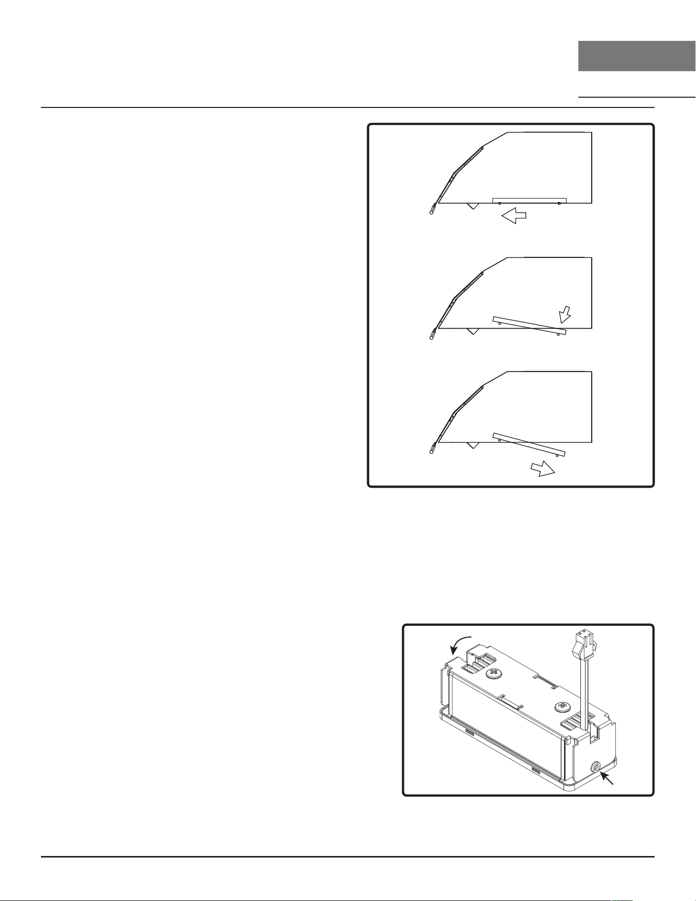
20
Okeanito Guide d’utilisation, d’entretien et d’installation
MUR
DESIGNER
OKEANITO
Entretien
Retrait du ltre à graisse (FIG. H)
1. Tirez le filtre vers l’avant de la hotte à l’aide des
poignées.
2. Faites pivoter l’arrière du filtre vers le bas.
3. Poussez le filtre vers l’arrière et retirez-le.
LumiLight LED pivotante
Dans le cas peu probable où votre LumiLight LED pivotante tomberait en panne, veuillez contacter
Zephyr pour commander des pièces de rechange. Consultez la page Liste des pièces et accessoires
pour les numéros de pièces et les coordonnées.
Retrait de LED (FIG. I)
1. Retirez les filtres à graisse.
2. (Le cas échéant) retirez les deux panneaux
d’espacement latéraux à l’aide de 2 vis pour chaque
panneau d’espacement.
3. Retirez les vis du panneau lumineux.
4. Débranchez le connecteur rapide de la lumière LED.
5. Retirez (2) vis des côtés par lumière LED.
6. Poussez la lumière LED à travers l’ouverture du
panneau lumineux.
FIG. I
FIG. H
1
2
3
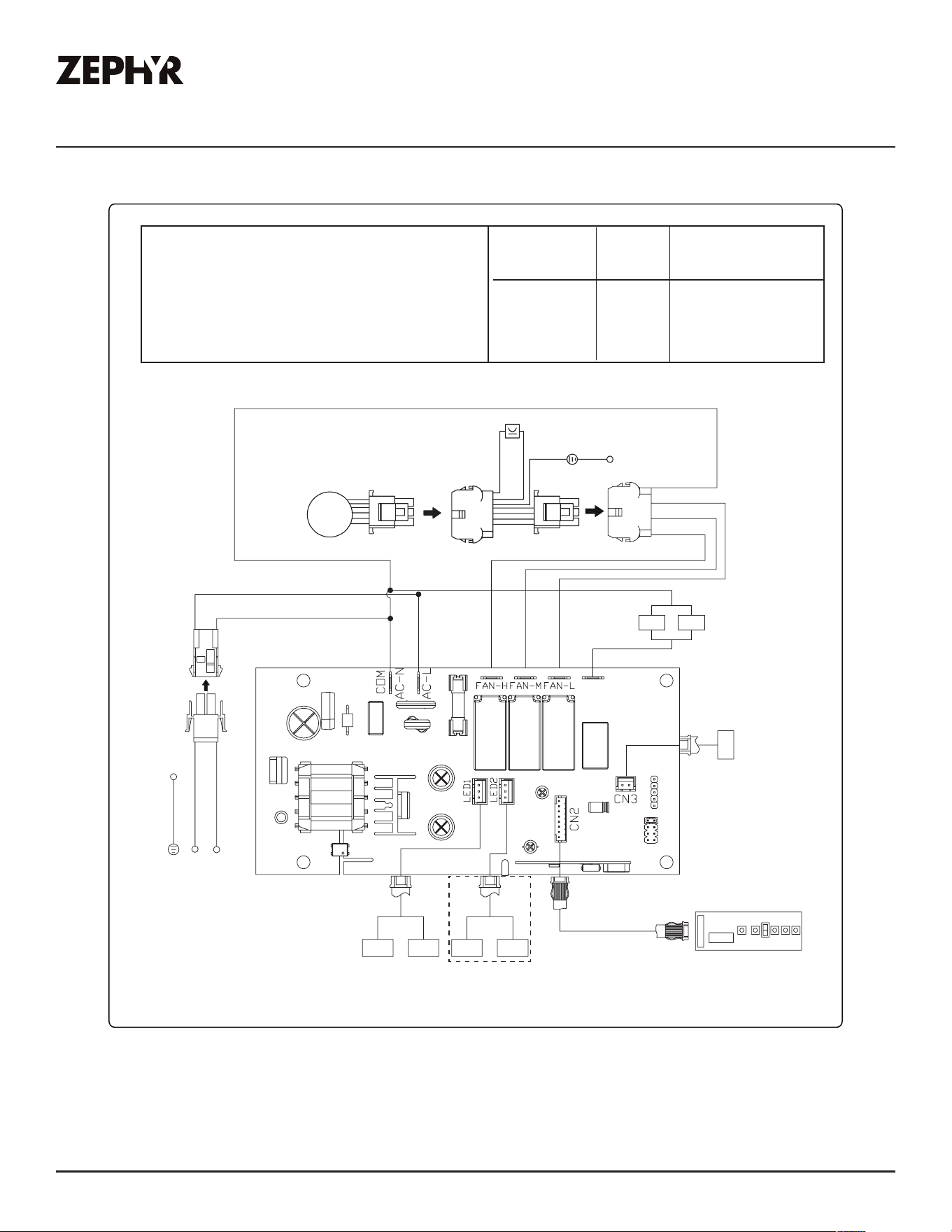
21
Okeanito Guide d’utilisation, d’entretien et d’installation
ZEPHYRONLINE.COM
Schéma de câblage
VOLTS
120
HZ
60
CBI-290C 0.8
CBI-390A 2.1
CBI-600A 2.6
BLANC
JAUNE
ROUGE
BLEU
VERT
NOIR
BLANC
CORPS
NOIR
BLANC
NOIR
BLANC
BLEU
ROUGE
JAUNE
PC de commande
LED LED LED LED
pour 48 po seulement
MOTEUR
CORPS
GRIS
NOIR
NOIR
BLANC
BLANC
NOIR
LL
B/W
SW
BLANC
Ampérage
maximal
Schéma de câblage du ventilateur interne
Remarques :Condensateur 3uF 250VCA ADAPTÉ CA120V 60Hz (CBI-290A)
Condensateur 25uF 250VCA ADAPTÉ CA120V 60Hz (CBI-390A/CBI-600A)
COK-E36/42/48CSX
COK-E36/42/48CBGX
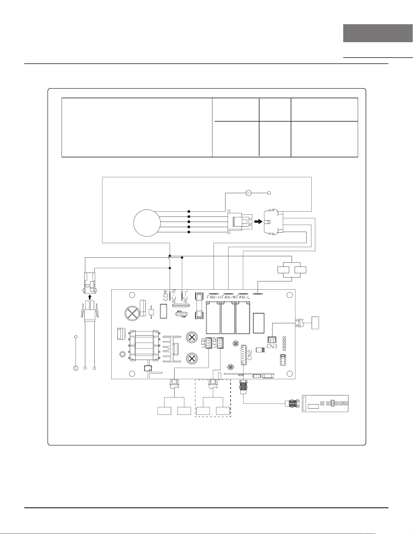
22
Okeanito Guide d’utilisation, d’entretien et d’installation
MUR
DESIGNER
OKEANITO
Schéma de câblage
CBE-1000 6.2
PBN-1000A 5.1
VOLTS
120
HZ
60
BLANC
JAUNE
ROUGE
BLEU
VERT
NOIR
BLANC
CORPS
NOIR
BLANC
NOIR
BLANC
BLEU
ROUGE
JAUNE
PC de commande
LED LED LED LED
pour 48 po seulement
NOIR
BLANC
BLANC
NOIR
LL
B/W
SW
BLANC
Ampérage
maximal
Schéma de câblage du ventilateur interne
Remarques :Condensateur 15uF 370VCA ADAPTÉ CA120V 60Hz (CBE-1000)
Condensateur*2 25uF 250VCA ADAPTÉ CA120V 60Hz (PBN-1000A)
CORPS
VERT
BLANC
NOIR
BLEU
ROUGE
MOTEUR
COK-E36/42/48CSX
COK-E36/42/48CBGX

23
Okeanito Guide d’utilisation, d’entretien et d’installation
ZEPHYRONLINE.COM
Dépannage
Problème possible Cause possible Solutions
Après l’installation,
l’appareil ne
fonctionne pas.
La source d’alimentation n’est pas
allumée.
Assurez-vous que le disjoncteur et
l’alimentation de l’unité sont allumés.
La ligne électrique et le
connecteur de verrouillage du
câble ne se connectent pas
correctement.
Vérifiez que la connexion d’alimentation
avec l’unité est correctement connectée.
Les câblages du tableau de
commande et du tableau de
commande sont déconnectés.
Assurez-vous que les câblages entre le
tableau de commutation et le tableau
de commande sont correctement
connectés.
Le tableau de commande ou
le tableau de commande est
défectueux.
Changer le tableau de commande ou le
tableau de commande.
La lumière fonctionne,
mais le ventilateur ne
tourne pas.
Le faisceau de câbles du
ventilateur externe ou interne est
peut-être déconnecté.
Assurez-vous que les fils sont connectés
au boîtier du tableau de commande.
Le système de protection
thermique détecte si le ventilateur
est trop chaud pour fonctionner
et arrête le ventilateur.
Le ventilateur fonctionnera correctement
après le refroidissement du système de
protection thermique.
Condensateur endommagé. Changer le condensateur.
La broche de la prise molex
du ventilateur n’établit pas de
contact.
Débranchez la prise molex du
ventilateur, vérifiez les broches à
l’intérieur de la prise pour voir si
la broche est enfoncée trop loin à
l’intérieur de la prise. Réinitialiser la
broche si nécessaire.
Le ventilateur est défectueux,
éventuellement grippé.
Changer le soueur.
L’appareil vibre. Le ventilateur n’est pas fixé en
place.
Serrez le ventilateur en place.
Roue de souante endommagée. Remplacez le ventilateur.
Le capot n’est pas fixé en place. Vérifiez l’installation de la hotte.
L’appareil sie. Un filtre n’est pas dans la bonne
position.
Ajustez les filtres jusqu’à ce que le
siement s’arrête.
Les raccords des tuyaux de
conduit ne sont pas scellés ou
connectés correctement.
Vérifiez les connexions des tuyaux de
conduit pour vous assurer que toutes les
connexions sont correctement scellées.
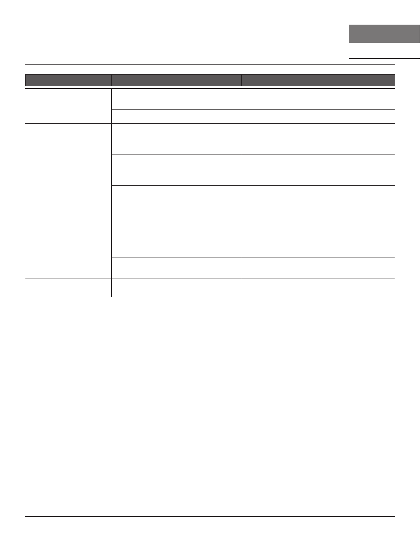
24
Okeanito Guide d’utilisation, d’entretien et d’installation
MUR
DESIGNER
OKEANITO
Dépannage
Problème possible Cause possible Solutions
Le ventilateur
fonctionne, mais pas
les lumières.
Le connecteur de la lumière LED
est déconnecté.
Connectez le connecteur de la lumière
LED.
Lumière LED défectueuse. Changer la lumière LED.
La hotte ne s’évacue
pas correctement.
Utiliser la mauvaise taille de
conduit.
Changez le conduit à au moins 6 po ou
plus pour le ventilateur interne et 8 po
ou plus pour le ventilateur externe.
La hotte peut être suspendue trop
haut à la table de cuisson.
Ajustez la distance entre la table de
cuisson et le bas de la hotte dans une
plage de 24 po et 36 po.
Le vent provenant des fenêtres
ouvertes ou des portes ouvertes
dans la zone environnante aecte
la ventilation de la hotte.
Fermez toutes les fenêtres et portes pour
éliminer le flux de vent extérieur.
Blocage dans l’ouverture du
conduit ou dans le réseau de
conduits.
Retirez tous les blocages des conduits
ou de l’ouverture des conduits.
Il y a trop de tours dans le
conduit.
Limitez le nombre de tours et/ou
augmentez la taille du conduit.
Le filtre vibre. Le filtre est lâche. Ajustez ou changez le filtre.

25
Okeanito Guide d’utilisation, d’entretien et d’installation
ZEPHYRONLINE.COM
Liste des pièces et accessoires
La description Numéro d’article
Pièces de rechange
Filtre à chicane (chacun) 50210036
Ampoule LED, 4W P12010008
LumiLight LED, 6W Z0B0052
Accessoires optionnels
Rallonge de couvercle de conduit Z1C-00TP
Ventilateur interne simple CBI-290C / CBI-600A
Ventilateur externe CBE-1000
Ventilateur en ligne PBN-1000A
Pour commander des pièces, visitez-nous en ligne à
http://store.zephyronline.com.

26
Okeanito Guide d’utilisation, d’entretien et d’installation
MUR
DESIGNER
OKEANITO
Remarques

27
Okeanito Guide d’utilisation, d’entretien et d’installation
ZEPHYRONLINE.COM
Garantie limitée
Zephyr Ventilation, LLC (désigné aux présentes sous le nom de « nous ») garantit au premier acheteur (désigné aux
présentes sous le nom de « vous » ou « votre ») de produits Zephyr (les « Produits ») que lesdits produits sont exempts
de défauts de fabrication ou de main-d’œuvre selon les conditions suivantes :
Garantie de trois ans sur les pièces : Garantie de trois ans à partir de la date d’achat originale du Produit. Nous
fournirons sans frais les Produits ou les pièces (y compris les ampoules LED, le cas échéant) de remplacement qui com-
portaient des défauts de fabrication. Nous pourrions choisir, à notre seule discrétion, de réparer ou de remplacer des
pièces avant de prendre la décision de remplacer le Produit.
Garantie limitée d’un an sur la main-d’œuvre : Garantie d’un an à partir de la date d’achat originale du Produit. Nous
couvrirons sans frais les frais de main-d’œuvre afférents à la réparation du Produit ou des pièces de remplacement qui
comportaient des défauts de fabrication. Un an après la date d’achat originale, vous serez responsable de tous les frais
de main-d’œuvre associés à la présente garantie.
Exclusions de la garantie : Cette garantie ne couvre que la réparation ou le remplacement, à notre gré, de pièces ou
de Produits défectueux et ne couvre aucun autre coût afférent aux Produits, dont, sans s’y limiter, les frais liés : (a) à
l’entretien normal des Produits et au remplacement des pièces consommables, comme les fluorescent, incandescence
ou halogèneampoules, les filtres métalliques, les filtres à charbon et les fusibles; (b) à tout Produit ou pièce ayant été
endommagé durant le transport ou étant le résultat d’un mauvais usage, d’une négligence, d’un accident, d’une installa-
tion incorrecte ou ne respectant pas les notices d’installation recommandées, d’un entretien ou d’une réparation inap-
proprié (dont ne nous sommes pas responsables); (c) à une utilisation commerciale ou ne correspondant pas à l’utilisa-
tion pour laquelle les Produits sont conçus; (d) à l’usure naturelle du fini, à l’usure due à un entretien inadéquat, à l’utili-
sation de produits nettoyants corrosifs ou abrasifs, de tampons nettoyeurs et de produits de nettoyage pour le four; (e)
aux éclats, entailles ou fissures résultant d’un abus ou d’une mauvaise utilisation du Produit; (f) aux déplacement d’un
technicien de service à votre domicile pour vous montrer comment utiliser les Produits; (g) aux dommages causés par
un accident, un incendie, une inondation, un cas fortuit; ou (h) Les installations personnalisées ou modifications qui ont
un impact maintenabilité du Produit. Si vous vous trouvez à l’extérieur du territoire que nous desservons, des frais
supplémentaires pourraient s’appliquer pour la livraison des produits à nos points de service désignés pour une répara-
tion sous garantie ou vous pourriez avoir à débourser les frais de déplacement du technicien à votre domicile pour que
le Produit soit réparé, enlevé ou réinstallé. Un an après la date d’achat originale du Produit, vous êtes également
responsable de tous les frais de main-d’œuvre associés à la présente garantie.
Restrictions de la garantie. NOTRE OBLIGATION DE RÉPARER OU DE REMPLACER, À NOTRE GRÉ, LE PRODUIT
CONSTITUE VOTRE SEUL ET UNIQUE RECOURS SOUS LA PRÉSENTE GARANTIE. NOUS NE NOUS PORTONS
PAS RESPONSABLES POUR TOUT DOMMAGE INDIRECT, ACCESSOIRE OU PARTICULIER RÉSULTANT OU AYANT
UN LIEN AVEC L’UTILISATION OU LE RENDEMENT DES PRODUITS. LES GARANTIES EXPRESSES DE LA SEC-
TION PRÉCÉDENTE SONT EXCLUSIVES ET TIENNENT LIEU DE TOUTE AUTRE GARANTIE EXPRESSE. PAR LES
PRÉSENTES, NOUS REJETONS ET EXCLUONS TOUTE AUTRE GARANTIE EXPRESSE POUR LES PRODUITS ET
TOUTES LES GARANTIES TACITES PRÉVUES PAR LA LOI, DONT CELLES RELATIVES À LA QUALITÉ
MARCHANDE OU À L'ADÉQUATION DU PRODUIT POUR UNE UTILISATION PARTICULIÈRE. Certains États ou
provinces n’autorisent pas les restrictions sur la durée d’une garantie implicite ou l’exclusion ou la restriction des dommag-
es indirects ou accessoires; par conséquent, les exclusions et restrictions mentionnées ci-dessus pourraient ne pas
s’appliquer à votre cas. Dans la mesure où une loi applicable interdit l’exclusion de garanties implicites, la durée de
toute garantie implicite applicable se limite à la période de deux ans décrite ci-dessus. L’unique objectif de toute descrip-
tion orale ou écrite est de présenter les Produits et celle-ci ne devrait pas être interprétée comme une garantie expresse.
Avant d’utiliser ou de permettre l’utilisation des Produits, vous devrez déterminer si les Produits conviennent aux utilisa-
tions prévues et vous devrez assumer tout risque et toute responsabilité relatifs à ces utilisations. Nous nous réservons
le droit d’utiliser des pièces reconstruites ou remises à neuf pour remplacer l’une des fonctionnalités dans le cadre de
la présente garantie ou de l’une des parties de la présente garantie. L’acheteur original ne peut transférer la présente
garantie et celle-ci n’est valide qu’aux États-Unis et au Canada.
Pour obtenir du service sous la garantie : Pour avoir droit à du service sous garantie, vous devez : (a) nous avertir
en utilisant l’adresse ou le numéro de téléphone inscrit ci-dessous dans les soixante jours suivant la détection du défaut;
(b) donner le numéro du modèle, le numéro d’identification de la pièce ainsi que le numéro de série; et (c) décrire la
nature de tout défaut de la pièce ou du Produit. Au moment de faire la demande de service sous garantie, vous devrez
présenter votre preuve d’achat et la preuve de la date d’achat originale. Si nous déterminons que les exclusions de la
garantie énumérées ci-dessus s’appliquent ou si vous vous trouvez dans l’incapacité de nous fournir la documentation
nécessaire pour obtenir du service, vous serez responsable de tous les frais d’expédition, de déplacement, de
main-d’œuvre ou de tout autre coût afférent au service.
Veuillez consulter notre site Web au www.zephyronline.com pour savoir si des révisions ont été apportées à la garantie.
Zephyr, 2277 Harbor Bay Parkway, Alameda, CA 94502
JAN21.0601
POUR OBTENIR UN SERVICE SOUS GARANTIE OU POUR TOUTE QUESTIONS LIÉES AU SERVICE
Les clients des États-Unis doivent appeler le: 1-888-880-8368 ou nous contacter à: zephyronline.com/contact
Clients du Canada, veuillez appeler: 1-800-361-0799 ou par courriel: [email protected]
Garantie limitée

28
Okeanito Guide d’utilisation, d’entretien et d’installation
MUR
DESIGNER
OKEANITO
Enregistrement du produit
Nous vous félicitons d’avoir acheté une produit
Zephyr. Veuillez prendre un moment pour enregis-
trer votre nouvelle produit au
www.zephyronline.com/registration
Zephyr Ventilation | 2277 Harbor Bay Pkwy. | Alameda, CA 94502 | 1.888.880.8368
Cet enregistrement rapide est utile à bien des
égards.
C’EST IMPORTANT
Il assure la couverture de votre garantie si vous avez
besoin de service après-vente.
À des fins d’assurance, il permet de confirmer que vous
êtes le propriétaire.
Il vous permet de recevoir des avis concernant des
modifications ou des rappels de produits.