1. SAFETY
WARNING! Use two or more people to move, assemble, and install the product to avoid any injury.
WARNING! DO NOT leave children unattended near the product.
WARNING! DO NOT stand on the product or lean on the drawers or worktop.
WARNING! Wear safety glasses when removing or repositioning the slides. The tools could slip, which may cause personal injury.
WARNING! DO NOT alter the product in any manner. For example, do not weld external lock bars or attach unapproved electrical
equipment. This may cause product damage, or injury.
WARNING! DO NOT overload products! The components of the product are designed to carry the following maximum weight capacities:
WARNING! Ensure Health & Safety, local authority, and general workshop practice regulations are adhered to when using these cabinets.
WARNING! Use the cabinets on level and solid ground, preferably concrete.
WARNING! Panels must be wall mounted. This is not a freestanding modular system.
▲ DANGER: Be careful when opening more than one drawer. The product could become unstable and tip. Which may cause product
damage or personal injury.
▲ DANGER: High risk of tipping if the product is not installed corectly. Securely attach the product to the wall to avoid serious injury.
8 DO NOT use these cabinets for any purpose other than that for which they are designed.
8 DO NOT use the cabinets outdoors.
8 DO NOT place the cabinets in a damp or wet location or an area where there is condensation.
8 DO NOT clean the cabinets with any solvents which may damage the surfaces or the protective coating.
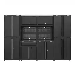
2. INTRODUCTION
Complete your garage or workshop with this stylish complete garage storage solution. All units are powder coated to protect against
scratches, mild solvents and general workshop use. Fully welded units offer a strong and professional finish conveniently packed and
delivered in one tidy pallet. Pegboard design wall panels allow for additional storage whilst protecting the wall behind the workbench.
Some simple assembly is required.
3. SPECIFICATION
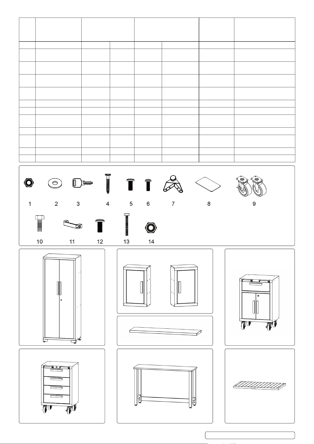
4. CONTENTS
NO. DESCRIPTION WALL
CABINET LOCKER
X2 X1
1-DRAWER 4-DRAWER
R CABINET R CABINET
X1 X1
52IN
WORKBENCH
X 1
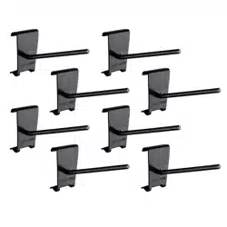
PEGBOARD
X 6
1 M6 HEX FLANGE
NUT
8 x 2 4 0 0 0 0
2 FLAT WASHER 4 x 2 4 0 0 0 4 x 6
STORAGE SYSTEM WITH MOBILE TROLLEY X 2
MODEL NO: APMS12OP
Thank you for purchasing a Sealey product. Manufactured to a high standard, this product will, if used according to these instructions,
and properly maintained, give you years of trouble free performance.
IMPORTANT: PLEASE READ THESE INSTRUCTIONS CAREFULLY. NOTE THE SAFE OPERATIONAL REQUIREMENTS, WARNINGS & CAUTIONS. USE
THE PRODUCT CORRECTLY AND WITH CARE FOR THE PURPOSE FOR WHICH IT IS INTENDED. FAILURE TO DO SO MAY CAUSE DAMAGE AND/OR
PERSONAL INJURY AND WILL INVALIDATE THE WARRANTY. KEEP THESE INSTRUCTIONS SAFE FOR FUTURE USE.
Refer to
instruction
manual
wear eye
protection during
assembly
APMS12OP Issue 1 30/08/23
Original Language Version
© Jack Sealey Limited
Cabinet Shelf Weight
Capicity (Kg.)
Drawer Weight
Capicity (Kg.)
Bottom Weight
Capicity (Kg.)
Top Weight
Capicity (Kg.)
Overall Weight Capicity (Kg.)
Locker 68.0 - 99.7 68.0 371.9
Wall Cabinet - - 22.6 - 22.6
1- drawer roller
cabinet
45.3 31.8x1 45.3 45.3 167.8
4- drawer roller
cabinet
- 31.8x4 - 45.3 172.3
52 inch workbench - - - 362.8 362.8
NO. DESCRIPTION WALL
CABINET LOCKER
X2 X1
1-DRAWER 4-DRAWER
R CABINET R CABINET
X1 X1
52IN
WORKBENCH
X 1
PEGBOARD
X 6
3 KEY 0 2 2 2 0 0
4 M5 X 50 HEX
TAPPING BOLT 4 x 2 4 0 0 0 4 x 6
5 M6 X 12 FLAT-HEAD
BOLT
8 x 2 20 0 0 0 0
6 M5 X 12 FLAT-HEAD
BOLT (on the door)
2 x 2 4 6 8 0 0
7 Adustable Leveling
Feet
0 4 0 0 0 0
8 Shelf 0 3 1 0 0 0
9 Casters 0 0 4 4 0 0
10 M8 x 20 Hex Flange
Bolt
0 0 16 16 0 0
11 Grab Handle 0 0 2 2 0 0
12 M8 x 16 Flat-Head
Bolt
0 0 4 4 8 0
13 M8 x 65 Hex Bolt 0 0 0 0 4 0
14 M8 Hex Flange Nut 0 0 0 0 4 0
APMS12OP Issue 1 30/08/23
Original Language Version
© Jack Sealey Limited
Note: Item 4 is intended to screw into the wall. Always
use fixings suitable for the weight of the item.
(Wall plugs not included).
Locker x1 1-drawer roller cabinet x1Wall Cabinet x2
Shelf to connect the wall cabinets x4
52in workbench x14 -drawer roller cabinet x1 Pegboard x6
6mm Philips Screwdriver 5mm Slotted Screwdriver
Cordless Power DrillSet Square Pencil
Adjustable Wrench
12’’ Magnetic Leveler Stud Finder Tape Measure
To unpack the products, start by placing the packages on a level floor. Take care when removing the packaging, and check all the contents are
included. If any item is missing contact your local Sealey authorised dealer where purchased. Recycle all packaging material after removed. Next
gather the tools required to construct the item.
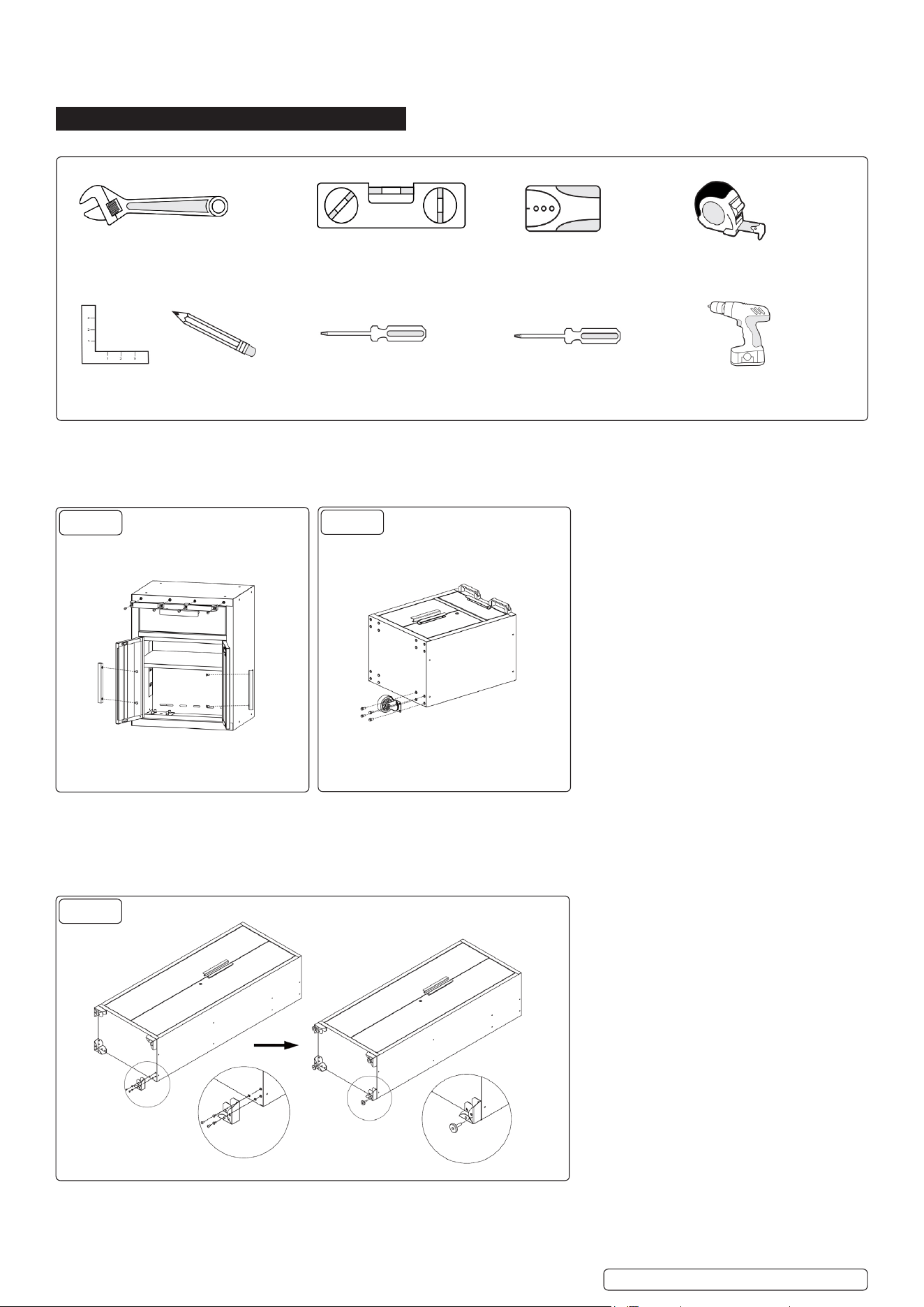
6. ASSEMBLY
6.1. TOOLS REQUIRED
6.2. INSTALLING THE HANDLES
Parts required: M5x12mm bolts. Grab handles. M8 x 16mm Flat-head bolts..
6.3. Attach the handle to the front of the doors using the M5x12mm flat head bolts. Repeat for all the doors and drawers.
6.4. Attach the grab handles to the cabinet, align the holes and fix with the M8x16mm flat head bolts. (See fig 1).
6.5. INSTALLING THE CASTERS
Parts required: Caster wheels. M8x20mm Hex Flange Bolts.
6.5.1. Lay the cabinet on a flat surface ensuring the item doesn’t get scratched. Use the packaging material to protect the finish.
6.5.2. Mount the four casters to each cabinet with the M8x20mm hex flange bolts. (See fig 2).
Note: The casters with brakes should be on the front side of the cabinet.
g. 1
g. 2
g. 3
APMS12OP Issue 1 30/08/23
Original Language Version
© Jack Sealey Limited
7.1. INSTALLING THE FEET
Parts required: M6x12mm Flat-Head Bolts. Adjustable Leveling Feet.
7.1.1. Lay the locker on a flat surface ensuring the item doesn’t get scratched. Use the packaging material to protect the finish. Attach the
adjustable leveling feet to the locker using the M6x12mm flat-head bolts. (See fig 3).
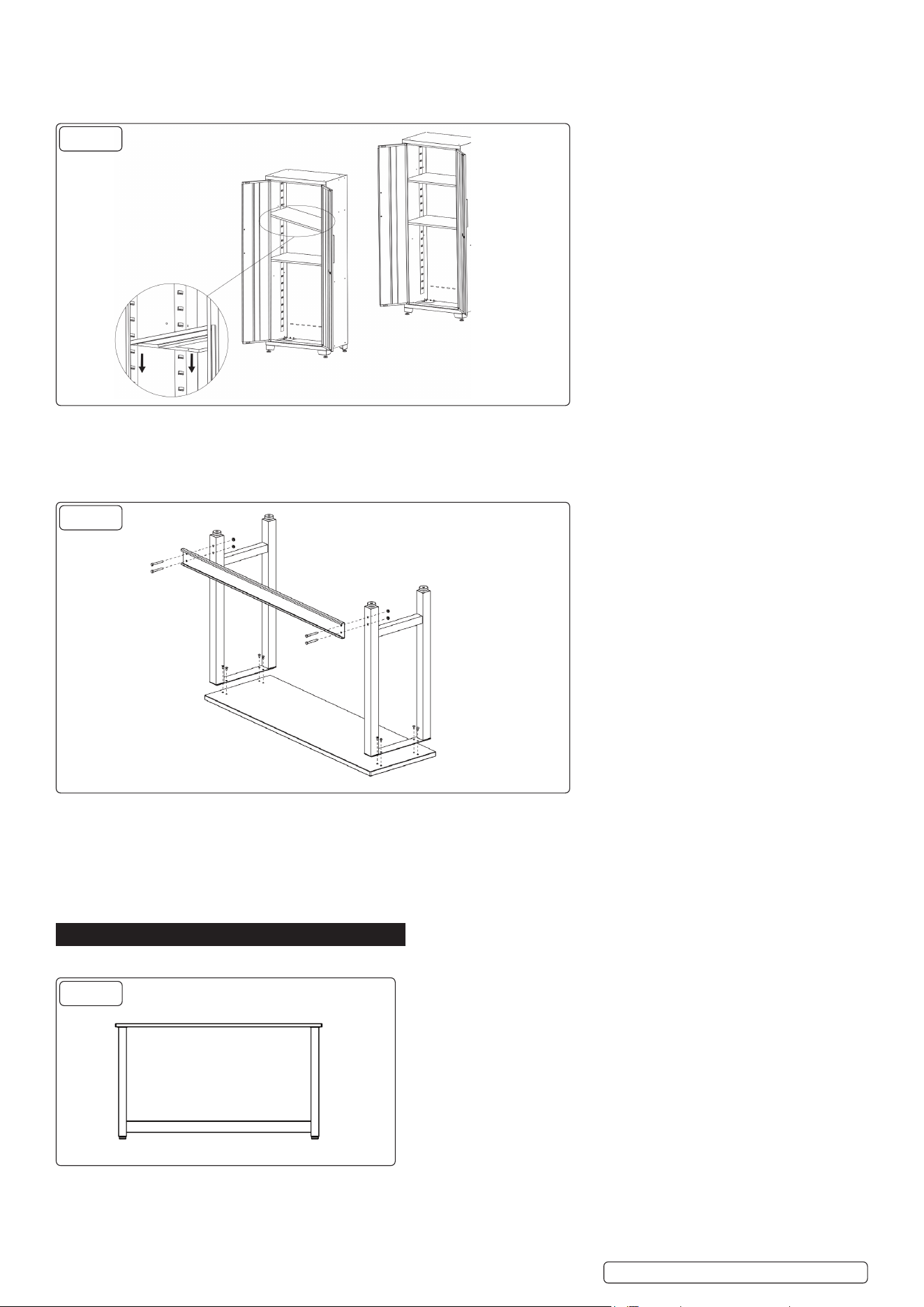
7.2. INSTALLING THE SHELVES
Parts required: Shelves.
7.2.1. Carefully insert the shelf into the slots either side of the cabinet.
7.2.2. Ensure all the shelves are placed stable. (See fig 4).
Note: The center shelf must be installed central to the lock on the cabinet door in order for the lock to work.
7.3. INSTALLING THE WORKBENCH
Parts required: M8x65mm Hex bolts. M8 Nuts. M8x16mm Flat-head bolt.
7.3.1. Lay the workbench on a flat surface ensuring the item doesn’t get scratched. Use the packaging material to protect the finish. Align the
holes on the legs with the base of the workbench. Use the M8x16mm bolts to connect the legs to the workbench.
7.3.2. Use four M8x65mm hex bolts and the M8 nuts to fasten the supports to the legs.
7.3.3. Tighten all bolts.
7.3.4. Stand the workbench up to finish the step. (See fig 5).
8. SETUP
8.1. Planning the position of the cabinets and workbench. (See g 6).
8.2. FIXING THE PEGBOARD TO THE WALL
Parts required: 2x4mm Flat washer. M5x50mm Hex Tapping Bolt. “Note: Wall plugs are not supplied with these units. You will need to use
plugs appropriate to the wall material in which you are mounting.”
8.2.1. Align the pegboard and x onto the wall using the 2x4mm Flat Washers and the M5x50mm Hex Tapping Bolts. (See fig 7).
g. 5
g. 6
APMS12OP Issue 1 30/08/23
Original Language Version
© Jack Sealey Limited
g. 4
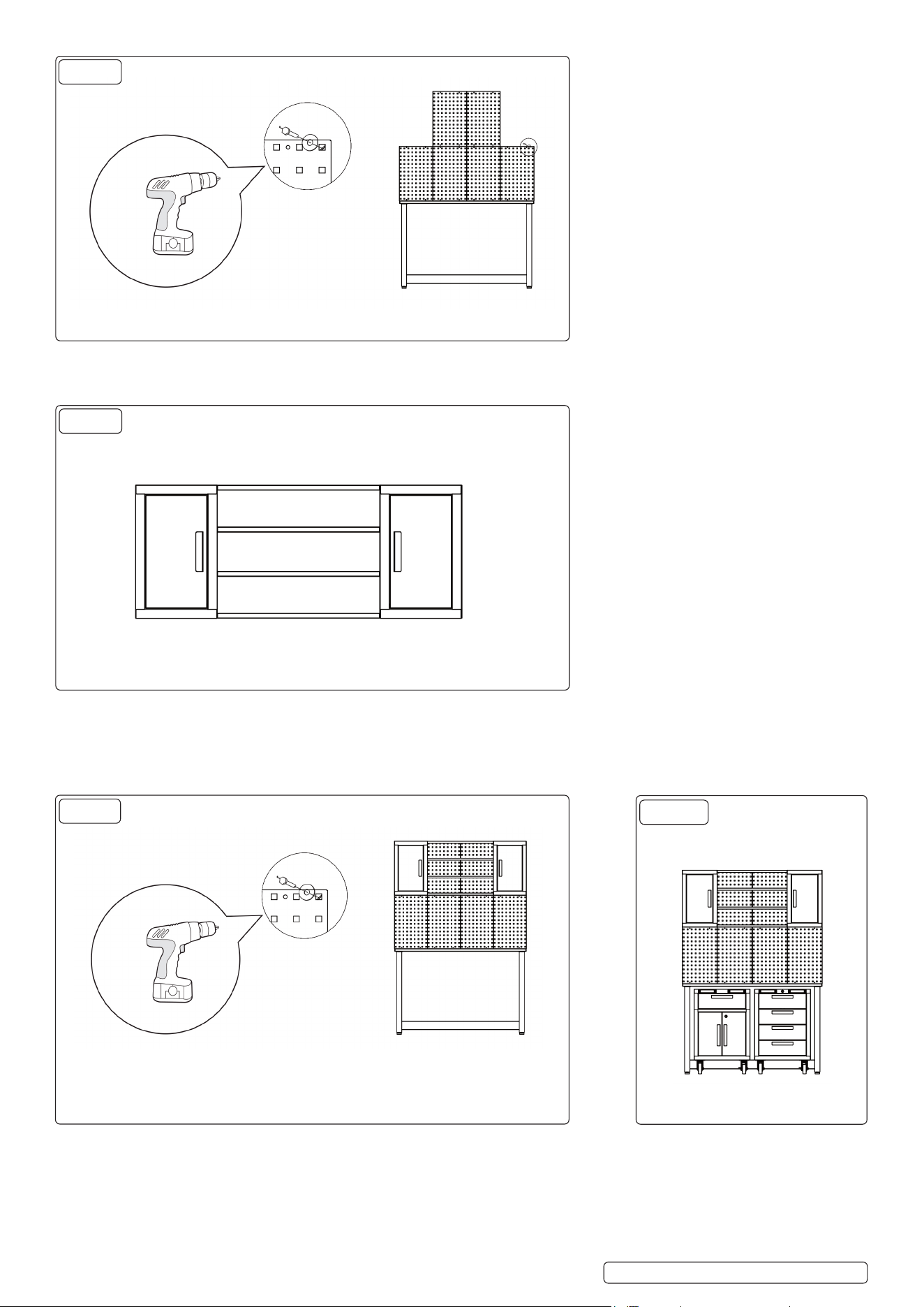
8.4. CONNECTING THE CABINETS TO THE SHELVES
Parts required: M6 Hex Flange Nut. M6x12mm Flat-Head Bolt.
8.5. Connect the two wall cabinets with the shelves using the M6x12mm Hex Flange Nuts and M6 Flat Head Bolts (See fig 8).
8.6. CONNECTING THE CABINETS TO THE WALL
Parts required: 2x8mm Flat Washer. M5x50mm Hex Tapping Bolt. Note: Wall plugs are not supplied with these units. You will need to use
plugs appropriate to the wall material in which you are mounting.”
8.7. Open the wall cabinet doors, connect the wall cabinet assembly to the wall using the 2x8mm Flat Washers and the M5x50mm Bolts.
Note: Two or more persons is recommended for this step. (See fig 9).
Roll the tool cabinet under the workbench. (See fig 10).
8.8. CONNECTING THE LOCKER TO THE WALL
Parts required: 2x4mm Flat Washers. M5x50mm Hex Tapping Bolt. Note: Wall plugs are not supplied with these units. You will need to
use plugs appropriate to the wall material in which you are mounting.”
8.9. Lean the cabinet against the table. Open the door of the locker and securely attach the locker onto the wall using the 2x4mm Flat Washers
g. 7
g. 8
g. 9
g. 10
APMS12OP Issue 1 30/08/23
Original Language Version
© Jack Sealey Limited
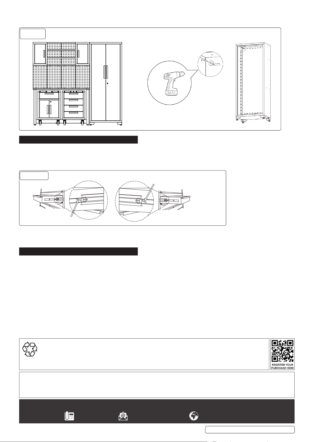
and the M5x50mm Hex Tapping Bolt to prevent it from tipping. (See fig 11 on the next page).
9. OPERATION
9.1. DRAWER REMOVAL
Pull the drawer out so that it’s almost fully extended. Push up on the black release lever on one side, while pulling down on the black
release lever on the other side. Hold the levers in the positions as illustrated below, pull the drawer outward until it is released from the
drawer slide. (See Fig 12).
9.2. Drawer Replacement
Extend the drawer slides from the cabinet. Insert the brackets on each side of the drawer into the slots in the slides, being carefull to
position them properly. Once inserted, close the drawer completely to send the slides to their proper positions.
10. MAINTENANCE
Lubricate the slides twice a year with a quality lubricant. This is especially necessary when the temperature drops, which may cause the
bearings to be dry. Periodically clean the drawers fronts, doors, handles and other surfaces with mild soap and water. For safety, use a
non flammable cleaning fluid. Grease and oil can be removed with most standard cleaning fluids.
g. 11
g. 12
Push up one side Push down one side
APMS12OP Issue 1 30/08/23
Original Language Version
© Jack Sealey Limited
Sealey Group, Kempson Way, Suffolk Business Park, Bury St Edmunds, Suffolk. IP32 7AR
01284 757500 sales@sealey.co.uk www.sealey.co.uk
NOTE: It is our policy to continually improve products and as such we reserve the right to alter data, specications and component parts
without prior notice.
IMPORTANT: No Liability is accepted for incorrect use of this product.
WARRANTY: Guarantee is 24 months from purchase date, proof of which is required for any claim.
ENVIRONMENT PROTECTION
Recycle unwanted materials instead of disposing of them as waste. All tools, accessories and packaging should be
sorted, taken to a recycling centre and disposed of in a manner which is compatible with the environment. When
the product becomes completely unserviceable and requires disposal, drain any uids (if applicable) into approved
containers and dispose of the product and uids according to local regulations.