Warning notices:
The design and specifications
are subject to change without
prior notice for product
improvement.
Rated voltage: 115V
Frequency: 60Hz
version E - 10 - 2023
EN
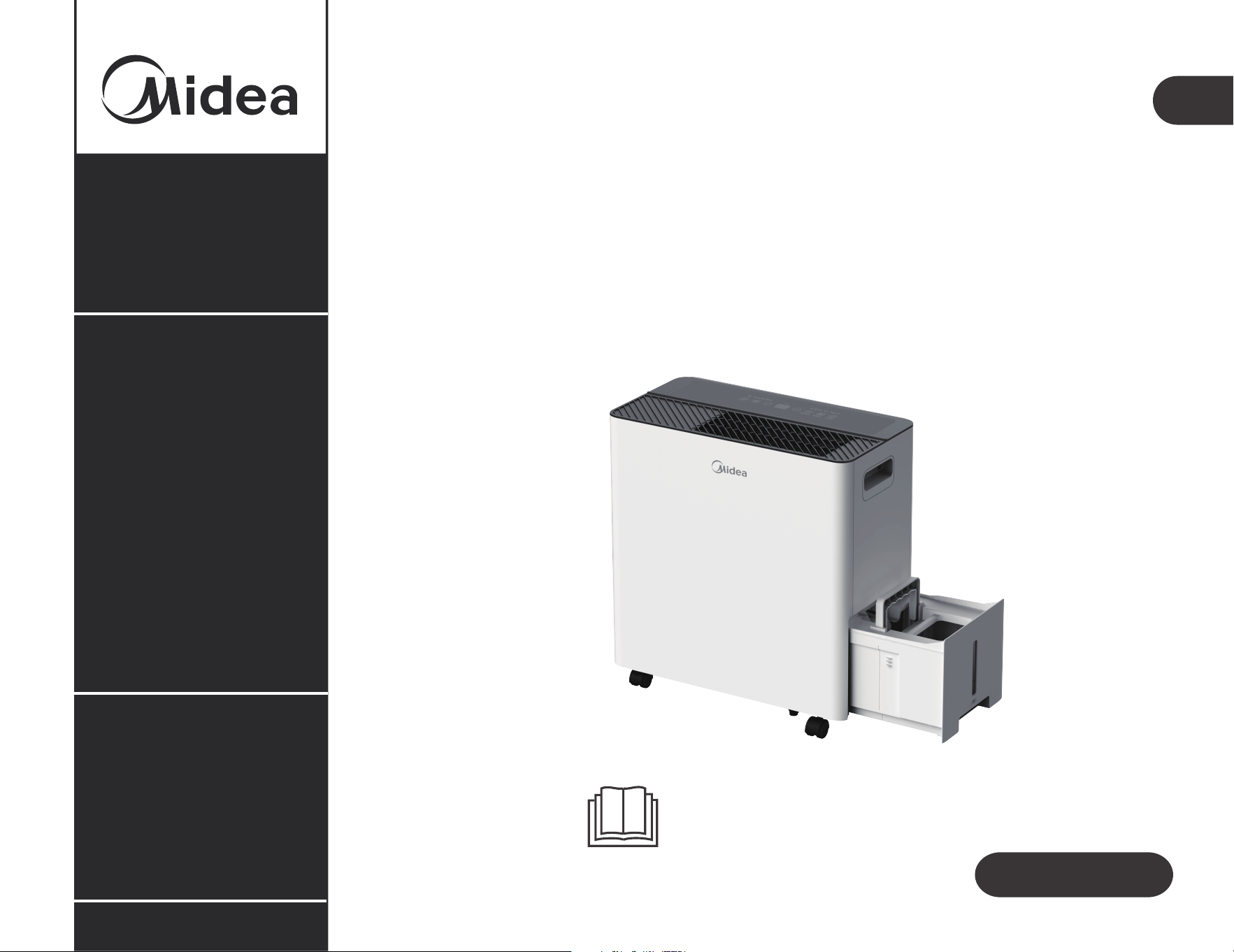
Owner’s Manual
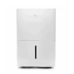
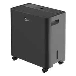
DEHUMIDIFIER
MAD50PS1AWT-C
IMPORTANT NOTE:
Before using your air conditioner, please read
this manual carefully and keep it for future reference.
www.midea.com
ITM. / ART. 1769129


Troubleshooting
01
CONTENTS
Safety precautions
Get to know your product
Get to know your product
Get to know your features
Care and Maintenance
12
17
20
29
App instructions
24
31
Operations
Removing collected water
Warranty
32
Service Center Operation Hours: Monday through Friday 8 a.m. to 7 p.m. EST
Saturday 9 a.m. to 4 p.m. EST
For support, please call the Service Center at 1-866-646-4332.
Language Spoken: English
Safety Precautions
WARNING
The signal word indicates a hazard with a high level of risk which, if not avoided, may result in
serious injury or death.
CAUTION
The signal word indicates a hazard with a low degree of risk which, if not avoided, may result in minor or
moderate injury.
Explanation of Symbols
Must read the warning message.
01
Read Safety Precautions Before Operation and Installation. To prevent property damage or personal injury,
these instructions must be followed. Incorrect operation due to ignoring of instructions
may cause damage or personal harm. The level of risk is shown by the following indications
CAUTION:
Risk of fire
flammable materials
Explanation of symbols displayed on the unit
CAUTION
This symbol shows that the operation manual should be read carefully.
CAUTION
This symbol shows that a service personnel should be handling this equipment with
reference to the installation manual.
CAUTION
This symbol shows that information is available such as the operating manual or
installation manual.
A2L
WARNING
Do not exceed the rating of the power outlet or
connection device.
Do not stop or switch off the unit by cutting off the
power.
Do not damage or use an unspecified power cord.
Do not modify power cord length or share the outlet with
other appliances.
Do not insert or pull out plug with wet hands.
Do not install the appliance in a location that may be
exposed to combustible gas.
Do not place the unit near a heat source.
Disconnect the power if strange sounds, smell, or smoke
comes from it.
ever try to take apart or repair the unit by
yourself.
Do not use the machine near flammable gas or
combustibles, such as gasoline, benzene, thinner, etc.
Do not drink or use the water drained from the unit.
Do not take the water bucket out during operation.
Do not use the unit in small spaces.
Do not put in places where water may splash onto
the unit.
N
02
Place the unit on a level, sturdy section of the floor.
Do not cover the intake or exhaust openings with cloth
or towels.
Care should be taken when using the unit in a room with
the following persons: infants, children, elderly people,
and
Do not use in areas where chemicals are handled.
Never insert your finger or other foreign objects into
grills or openings. Take special care to warn children of
these dangers.
people with reduced physical, sensory, or mental
capabilities.
Do
not place
heavy objects on the
power
cord and take
care
so that the
cord is not
compressed.
Do
not
climb
up, on, or
sit
on the unit.
Always insert the filters securely. Clean filter once
every
two
weeks. See page 29 for filter cleaning instructions.
the
power,
contact a qualified service
technician.
Do
not
place
flower
vases
or
other
water
filled
containers
on
top of the unit.
Do
not
use
extension
cords.
CAUTION
Prior to cleaning or other maintenance, the appliance
must be disconnected from the supply .
Do not install the appliance in a location that may be
exposed to combustible gas. If combustible gas
accumulates around the unit, it may cause fire.
unit and unplug it from the main power supply
immediately. Visually inspect the unit to ensure there is
no damage. If you suspect the unit has been damaged,
contact a technician or customer service for assistance.
If the supply cord is damaged, it must be replaced by the
manufacturer, its service agent or a similarly qualified
person in order to avoid a hazard.
This appliance is not intended for use by persons
(including children) with reduced physical, sensory or
mental capabilities or lack of experience and knowledge,
unless they have been given supervision or instruction
concerning use of the appliance by a person responsible
for their safety.
Children should be supervised to ensure that they do not
play with the appliance.
Our product should not be used in a water damaged
environment.
power
03
damage to the machine due to lightning.
Do not run cord under carpeting. Do not cover cord with
throw rugs, runners, or similar coverings. Do not route
cord under furniture or appliances. Arrange cord away
Do not operate unit with a damaged cord or plug.
Discard unit or return to an authorized service facility for
examination and/or repair.
To reduce the risk of fire or electric shock, do not use
this fan with any solid-state speed control device.
The appliance shall be installed in accordance with
national wiring regulations.
Contact the authori ed service technician for repair or
maintenance of this unit.
The manufacturer's nameplate is located on the panel
of the unit and contains electrical and other technical
data specific to this unit.
z
Be sure the unit is properly grounded. To minimize
shock and fire hazards, proper grounding is important.
The power cord is equipped with a three-prong
grounding plug for protection against shock hazards.
Your unit must be used in
a properly grounded wall
receptacle. If the wall receptacle you intend to use is not
adequately grounded or protected by a time delay fuse
or circuit breaker(please refer to the nameplate for the
electrical data), have a qualified electrician install the
proper receptacle.
The unit's circuit board (PCB) is designed with a fuse to
provide overcurrent protection. Specifications of the
fuse are printed on the circuit board, such as:
T 3.15A/250V (or 350V), etc.
Electronic Work
DISPLAY
MAIN
CONTROL
POWER
SUPPLY
CORD
04
NOTE:
The
cographs are
for
explanation
purpose only.
Your machine may be slightly different.
The actual shape shall prevail.
WARNING:
- Servicing shall only be performed as recommended by the equipment manufacturer. Maintenance and repair
requiring the assistance of other skilled personnel shall be carried out under the supervision of a person
competent in the use of flammable refrigerants.
- Before performing any electrical
or
wiring
work,
turn
off the
main
power
to the
system.
- DO NOT modify the length of the power cord or use an extension cord to power the unit.
- DO NOT share a single outlet with other electrical appliances. Improper power supply can cause fire or
electrical
shock.
- Please follow the instructions carefully to handle, install, clean and service the appliance to avoid any damage
or hazard.

Flammable
Refrigerant R32 is used within appliance.
- When maintaining or disposing the appliance, the refrigerant (R32) shall be recovered properly, shall not
discharge to air directly.
- Compliance with national gas regulations shall be observed.
- Keep ventilation openings clear of obstruction.
- The appliance shall be stored so as to prevent mechanical damage from occurring.
- A warning that the appliance shall be stored in a well-ventilated area where the room size corresponds to the
room area as specified for operation.
- Any person who is involved with working on or breaking into a refrigerant circuit should hold a current valid
certificate from an industry-accredited assessment authority, which authorizes their competence to handle
refrigerants safely in accordance with an industry recognized assessment specification.
Examples for such working procedures are:
• breaking into the refrigerating circuit;
• opening of sealed components;
• opening of ventilated enclosures.
- No open fire or device like switch which may generate spark/arcing shall be around appliance to avoid
causing ignition of the flammable refrigerant used. Please follow the instruction carefully to store or maintain
the appliance to prevent mechanical damage from occurring.
-Do not use means to accelerate the defrosting process or to clean, other than those recommended by the
manufacturer.
- The appliance shall be stored in a room without continuously operating ignition sources (for example: open
flames, an operating gas appliance) and ignition sources (for example: an operating electric heater) close to
the appliance.
- Do not pierce or burn.
- Be aware that the refrigerants may not contain an odor.
05

How to handle equipment containing flammable refrigerants
06
See transport regulations.
1.Transport of equipment containing flammable refrigerants
See local regulations.
2.Marking of equipment using signs
See national regulations.
3.Disposal of equipment using flammable refrigerants
The storage of equipment should be in accordance with the manufacturer's instructions.
4.Storage of equipment/appliances
Storage package protection should be constructed such that mechanical damage to the equipment inside the
package will not cause a leak of the refrigerant charge. The maximum number of pieces of equipment permitted
to be stored together will be determined by local regulations.
5.Storage of packed (unsold) equipment
1)Checks to the area
Prior to beginning work on systems containing flammable refrigerants, safety checks are necessary to ensure
that the risk of ignition is minimized. For repair to the refrigerating system, the following precautions shall be
complied with prior to conducting work on the system.
2)Work procedure
Work shall be undertaken under a controlled procedure so as to minimize the risk of a flammable gas or vapour
being present while the work is being performed.
3)General work area
All maintenance staf and others working in the local area shall be instructed on the nature of work being
carried out. Work in confined spaces shall be avoided. The area around the workspace shall be sectioned of.
Ensure that the conditions within the area have been made safe by control of flammable material.
4)Checking for presence of refrigerant
The area shall be checked with an appropriate refrigerating detector prior to and during work, to ensure the
technician is aware of potentially flammable atmospheres. Ensure that the leak detection equipment being
used is suitable for use with flammable refrigerants, i.e. non-sparking, adequately sealed or intrinsically safe.
6.Information on servicing

The actual refrigerant charge is in accordance with the room size within which the refrigerant containing parts
are installed;
The ventilation machinery and outlets are operating adequately and are not obstructed; If an indirect
refrigerating circuit is being used, the secondary circuit shall be checked for the presence of refrigerant; Marking
to the equipment continues to be visible and legible. Markings and signs that are illegible shall be corrected;
Refrigerating pipe or components are installed in a position where they are unlikely to be exposed to any
substance which may corrode refrigerant containing components, unless the components are constructed of
materials which are inherently resistant to being corroded or are suitably protected against being so corroded.
5)Presence of fire extinguisher
If any hot work is to be conducted on the refrigeration equipment or any associated parts, appropriate fire
extinguishing equipment shall be available to hand. Have a dry powder or CO2 fire extinguisher adjacent to the
charging area.
6)No ignition sources
No person carrying out work in relation to a refrigerating system which involves exposing any pipe work that
contains or has contained flammable refrigerant shall use any sources of ignition in such a manner that it may
lead to the risk of fire or explosion. All possible ignition sources, including cigarette smoking, should be kept
sufficiently far away from the site of installation, repairing, removing and disposal, during which flammable
refrigerant can possibly be released to the surrounding space. Prior to work taking place, the area around the
equipment is to be surveyed to make sure that there are no flammable hazards or ignition risks. No Smoking
signs shall be displayed.
7)Ventilated area
Ensure that the area is in the open or that it is adequately ventilated before breaking into the system or
conducting any hot work. A degree of ventilation shall continue during the period that the work is carried out.
The ventilation should safely disperse any released refrigerant and preferably expel it externally into the
atmosphere.
8)Checks to the refrigerating equipment
Where electrical components are being changed, they shall be fit for the purpose and to the correct
specification. At all times the manufacturer's maintenance and service guidelines shall be followed. If in doubt
consult the manufacturer's technical department for assistance. The following checks shall be applied to
installations using flammable refrigerants:
07

08
9)Checks to electrical devices
Repair and maintenance to electrical components shall include initial safety checks and component inspection
procedures. If a fault exists that could compromise safety, then no electrical supply shall be connected to the
circuit until it is satisfactorily dealt with. If the fault cannot be corrected immediately but it is necessary to
continue operation, an adequate temporary solution shall be used. This shall be reported to the owner of the
equipment so all parties are advised.
Initial safety checks shall include:
That capacitors are discharged: this shall be done in a safe manner to avoid possibility of sparking; That there
are no live electrical components and wiring are exposed while charging, recovering or purging the system;
That there is continuity of earth bonding.
7.Sealed electrical components shall be replaced
1)During repairs to sealed components, all electrical supplies shall be disconnected from the equipment being
worked upon prior to any removal of sealed covers, etc. If it is absolutely necessary to have an electrical
supply to equipment during servicing, then a permanently operating form of leak detection shall be located at
the most critical point to warn of a potentially hazardous situation.
2)Particular attention shall be paid to the following to ensure that by working on electrical components, the
casing is not altered in such a way that the level of protection is affected.
This shall include damage to cables, excessive number of connections, terminals not made to original
specification, damage to seals, incorrect fitting of glands, etc.
Ensure that apparatus is mounted securely.
Ensure that seals or sealing materials have not degraded such that they no longer serve the purpose of
preventing the ingress of flammable atmospheres. Replacement parts shall be in accordance with the
manufacturer's specifications.
NOTE: The use of silicon sealant may inhibit the efectiveness of some types of leak detection equipment.
Intrinsically safe components do not have to be isolated prior to working on them.
8.Intrinsically safe components must be replaced
Do not apply any permanent inductive or capacitance loads to the circuit without ensuring that this will not
exceed the permissible voltage and current permitted for the equipment in use.
Intrinsically safe components are the only types that can be worked on while live in the presence of a flammable
atmosphere.
The test apparatus shall be at the correct rating.Replace components only with parts specified by the
manufacturer. Other parts may result in the ignition of refrigerant in the atmosphere from a leak.
9.Cabling
Check that cabling will not be subject to wear, corrosion, excessive pressure, vibration, sharp edges or any other
adverse environmental effects. The check shall also take into account the effects of aging or continual vibration
from sources such as compressors or fans.

Under no circumstances shall potential sources of ignition be used in the searching for or detection of refrigerant
leaks. A halide torch (or any other detector using a naked flame) shall not be used.
The following leak detection methods are deemed acceptable for systems containing flammable refrigerants.
Electronic leak detectors shall be used to detect flammable refrigerants, but the sensitivity may not be adequate,
or may need re-calibration.
(Detection equipment shall be calibrated in a refrigerant-free area).
Ensure that the detector is not a potential source of ignition and is suitable for the refrigerant used. Leak
detection equipment shall be set at a percentage of the LFL of the refrigerant and shall be calibrated to the
refrigerant employed and the appropriate percentage of gas (25 % maximum) is confirmed. Leak detection
fluids are suitable for use with most refrigerants but the use of detergents containing chlorine shall be avoided
as the chlorine may react with the refrigerant and corrode the copper pipe-work.
If a leak is suspected, all naked flames shall be removed/extinguished. If a leakage of refrigerant is found which
requires brazing, all of the refrigerant shall be recovered from the system, or isolated (by means of shut off
valves) in a part of the system remote from the leak. Removal of refrigerant shall be according to Removal and
evacuation.
10.Detection of flammable refrigerants
When breaking into the refrigerant circuit to make repairs - or for any other purpose - conventional procedures shall
be used. However, for flammable refrigerants it is important that best practice be followed, since flammability is a
consideration. The following procedure shall be adhered to:
-safely remove refrigerant following local and national regulations;
-evacuate;
-purge the circuit with inert gas (optional for A2L);
-evacuate (optional for A2L);
-continuously flush or purge with inert gas when using flame to open circuit; and
-open the circuit.
The refrigerant charge shall be recovered into the correct recovery cylinders if venting is not allowed by local and
national codes. For appliances containing flammable refrigerants, the system shall be purged with oxygen-free n
flammable refrigerants. This process might Compressed air or oxygen shall not be used for purging refrigerant systems.
For appliances containing flammable refrigerants, refrigerants purging shall be achieved by breaking the vacuum
in the system with oxygen-free nitrogen and continuing to fill until the working pressure is achieved, then venting
to atmosphere, and finally pulling down to a vacuum (optional for A2L). This process shall be repeated until no
refrigerant is within the system (optional for A2L). When the final oxygen-free nitrogen charge is used. the system
shall be vented down to atmospheric pressure to enable work to take place.
The outlet for the vacuum pump shall not be close to any potential ignition sources, and ventilation shall be available.
11.Removal and evacuation
09

The refrigerant charge shall be recovered into the correct recovery cylinders if venting is not allowed by local
and national codes. For appliances containing flammable refrigerants, the system shall be purged with
oxygen-free nitrogen to render the appliance safe for flammable refrigerants. This process might need to be
repeated several times. Compressed air or oxygen shall not be used for purging refrigerant systems. For
appliances containing flammable refrigerants, refrigerants purging shall be achieved by breaking the vacuum in
the system with oxygen-free nitrogen and continuing to fill until the working pressure is achieved, then venting
to atmosphere, and finally pulling down to a vacuum (optional for A2L). This process shall be repeated until no
refrigerant is within the system (optional for A2L). When the final oxygen-free nitrogen charge is used, the
system shall be vented down to atmospheric pressure to enable work to take place. Ensure that the outlet for the
vacuum pump is not close to any potential ignition sources and that ventilation is available.
In addition to conventional charging procedures, the following requirements shall be followed. Ensure that
contamination of different refrigerants does not occur when using charging equipment. Hoses or lines shall be
as short as possible to minimise the amount of refrigerant contained in them. Cylinders shall be kept in an
appropriate position according to the instructions. Ensure that the refrigeration system is earthed prior to
charging the system with refrigerant. Label the system when charging is complete (if not already). Extreme care
shall be taken not to overfill the refrigeration system. Prior to recharging the system it shall be pressure tested
with OFN. The system shall be leak tested on completion of charging but prior to commissioning. A follow up
leak test shall be carried out prior to leaving the site.
12.Charging procedures
Before carrying out this procedure, it is essential that the technician is completely familiar with the equipment
and all its detail. It is recommended good practice that all refrigerants are recovered safely. Prior to the task
being carried out, an oil and refrigerant sample shall be taken in case analysis is required prior to re-use of
reclaimed refrigerant. It is essential that electrical power is available before the task is commenced.
a)Become familiar with the equipment and its operation.
b)Isolate system electrically.
13.Decommissioning
c)Before attempting the procedure ensure that: Mechanical handling equipment is available, if required, for
handling refrigerant cylinders;
All personal protective equipment is available and being used correctly; The recovery process is supervised at
all times by a competent person; Recovery equipment and cylinders conform to the appropriate standards.
d)Pump down refrigerant system, if possible.
e)If a vacuum is not possible, make a manifold so that refrigerant can be removed from various parts of the
system.
f)Make sure that cylinder is situated on the scales before recovery takes place.
10

11
g)Start the recovery machine and operate in accordance with instructions.
h)Do not overfill cylinders. (No more than 80 % volume liquid charge).
i)Do not exceed the maximum working pressure of the cylinder, even temporarily.
j)When the cylinders have been filled correctly and the process completed, make sure that the cylinders and the
equipment are removed from site promptly and all isolation valves on the equipment are closed off.
k)Recovered refrigerant shall not be charged into another refrigeration system unless it has been cleaned and
checked.
14.Labelling
Equipment shall be labeled stating that it has been de-commissioned and emptied of refrigerant. The label shall
be dated and signed.
Ensure that there are labels on the equipment stating the equipment contains flammable refrigerant.
15.Recovery
When removing refrigerant from a system, either for servicing or decommissioning, it is recommended good practice
that all refrigerants are removed safely.
When transferring refrigerant into cylinders, ensure that only appropriate refrigerant recovery cylinders are employed.
Ensure that the correct number of cylinders for holding the total system charge is available. All cylinders to be used
are designated for the recovered refrigerant and labeled for that refrigerant (i.e. special cylinders for the recovery of
refrigerant). Cylinders shall be complete with pressure-relief valve and associated shut-off valves in good working
order. Empty recovery cylinders are evacuated and, if possible, cooled before recovery occurs.
The recovery equipment shall be in good working order with a set of instructions concerning the equipment that is at
hand and shall be suitable for the recovery of the flammable refrigerant. If in doubt, the manufacturer should be
consulted. In addition, a set of calibrated weighing scales shall be available and in good working order. Hoses shall be
complete with leak-free disconnect couplings and in good condition.
The recovered refrigerant shall be processed according to local legislation in the correct recovery cylinder, and the
relevant waste transfer note arranged. Do not mix refrigerants in recovery units and especially not in cylinders.
If compressors or compressor oils are to be removed, ensure that they have been evacuated to an acceptable level to
make certain that flammable refrigerant does not remain within the lubricant. The compressor body shall not be
heated by an open flame or other ignition sources to accelerate this process. When oil is drained from a system, it shall
be carried out safely.
Non-duct connected appliances containing A2L refrigerants with the supply and return air openings in the
conditioned space may have the body of the appliance installed in open areas such as false ceilings not being
used as return air plenums, as long as the conditioned air does not directly communicate with the air of the false
ceiling.
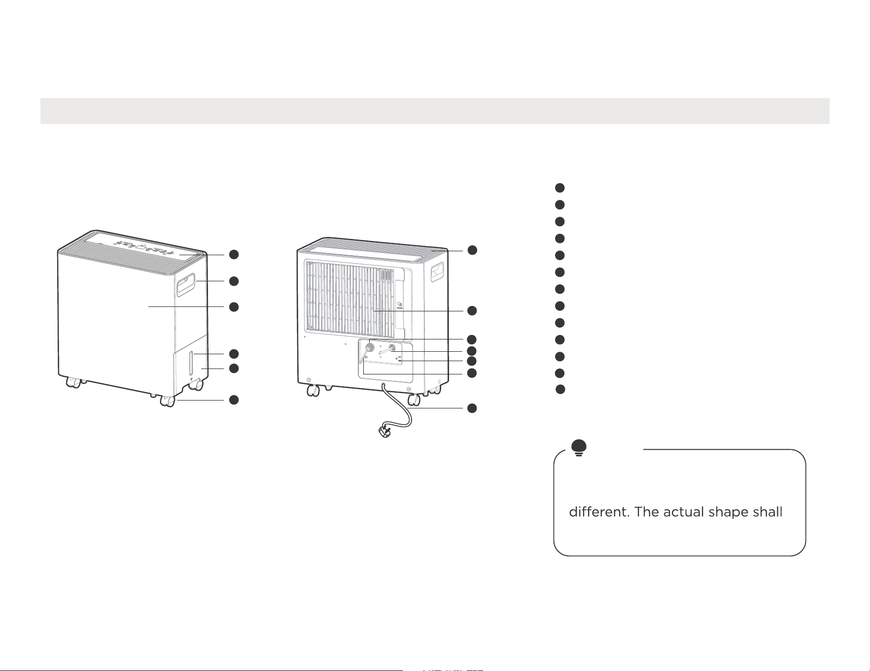
NOTE
All the illustrations in the manual
are for explanation purpose only.
Your machine may be slightly
prevail. The unit can be controlled
by the unit control panel.
1
2
3
4
5
6
7
8
9
10
11
Control panel
Front panel
Water level window
Water bucket
Handle(both sides)
Air outlet grille
Continuous drain hose outlet
Power plug storage
Caster (Optional)
Power cord and plug
12
Pump drainage
Air filter (Air inlet grille)
Identification of parts
Get to know your product
Name of each component of the product
1
2
3
4
5
6
12
7
8
9
10
11
13
12
13
Water plug
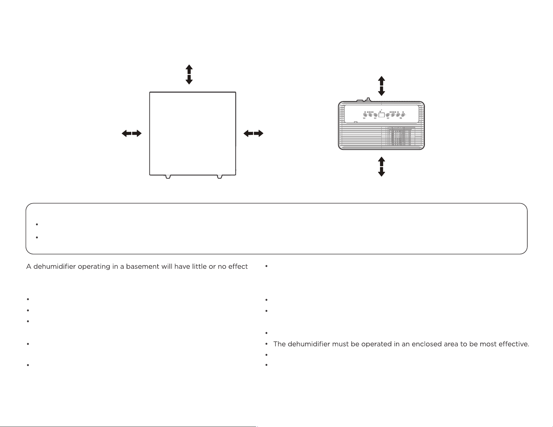
Positioning the unit
in drying an adjacent enclosed storage area, such as a closet, unless
there is adequate circulation of air in and out of the area.
Do not use outdoors.
This dehumidifer is intended for indoor residential applications only.
This dehumidifer should not be used for commercial or industrial
applications.
Place the dehumidifier on a smooth, level floor strong enough to
support the unit with a full bucket of water.
Allow atleast 20cm of air space on all sides of the unit for good air
circulation (atleast 40cm of air space on air outlet).
20cm
or more
20cm
or more
Front view
Top view
40cm
or more
40cm
or more
40cm
or more
Safe distance requirements
13
Casters - install all four on the bottom of the unit.
The unit is with universal wheels that can move in all directions flexibly.
Do not force casters to move over carpet. Do not move the unit with water in the bucket. The unit may tip over and spill
water.
Place
the unit in
an
area
where the
temperature
will
not
fall below
5° C(41° F).
The
coils
can
become
covered with
frost
at
temperatures below
5° C(41° F),
which may
reduce performance.
Place
the unit
away from the
clothes dryer, heater
or
radiator.
Use the unit
to prevent
moisture
damage anywhere books or
valuables are
stored.
Use the dehumidifier
in
a
basement
to help prevent moisture damage.
Close
all doors,
windows and
other
outside
openings
to
the
room.
Before tilting or moving the unit in any way, disconnect the power
cord, take
out the bucket, and open the
continuous drain
outlet
to
empty the
water.
When using your product
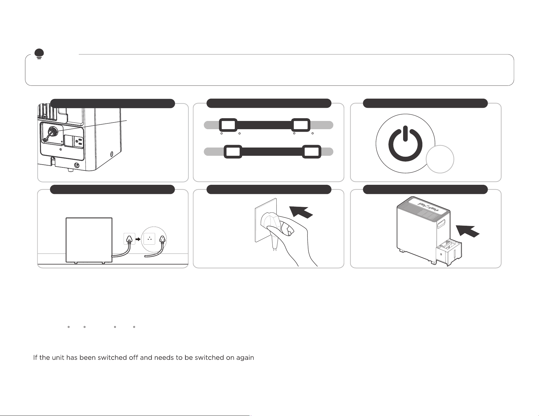
Preparations for product use.
•
•
When first using the dehumidifier, operate the unit continuously
24 hours. Ensure that the plastic cover of the bucket (Page 15)
This unit is designed to operate with a working environment
between 5 C/41 F and 32 C/90 F, and between 30%(RH) and 80%(RH).
When use in open space with open windows, condensation may
form on the surface of the product, which is normal.
quickly , allow approximately three minutes for the correct operation
to resume.
•
•
•
•
Do not connect the dehumidifier to a multiple socket
outlet, which is also being used for other electrical appliances.
Select a suitable location, making sure you have easy access to an
electrical outlet.
Plug the unit into a electrical socket-outlet with ground connection.
Make sure the Water bucket is correctly fitted otherwise the unit will
not operate properly.
•
•
NOTE
When there is water in the bucket and you want to move the unit, pls move the unit steadily in case that water
spills or the unit tips over.
3 ) 8 %(RH)
Operating TEMP.
Operating Humidity
Min.
Min.
Max.
Max.
5 C/ F
32 C/90 F
3min
After a quick restart,
wait 3 minutes for the
operation to resume.
*Please refer to the actual
plug, and the legend is for
reference only.
Working condition requirement Precautions for use
Correct power connection Proper installation of water tank
First time using
Ensure the water plug
is securely installed
and operate the unit
continuously for 24 hours.
Ground connection
for
is in continuous dehumidification mode and does
not leak.
n
14
*
It is highly recommended
to insert the plug into a
single
socket outlet.
41
0%(RH 0
securely installed
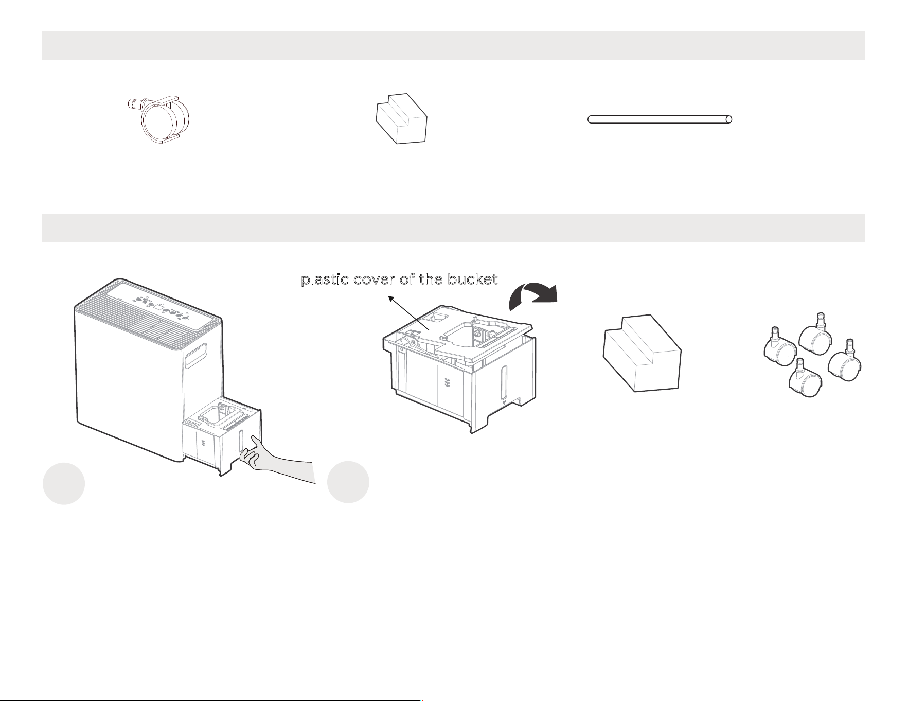
Accessories
Pump drain hose (1 pc)
Caster
(4 pc)
2
Caster installation
Caster (4 pc)
Pull out the water
bucket
Take out a cushion pad and four casters from the
bucket, then reinstall the water bucket
Cushion pad (1 pc)
15
1
Cushion pad(1 pc)
plastic cover of the bucket
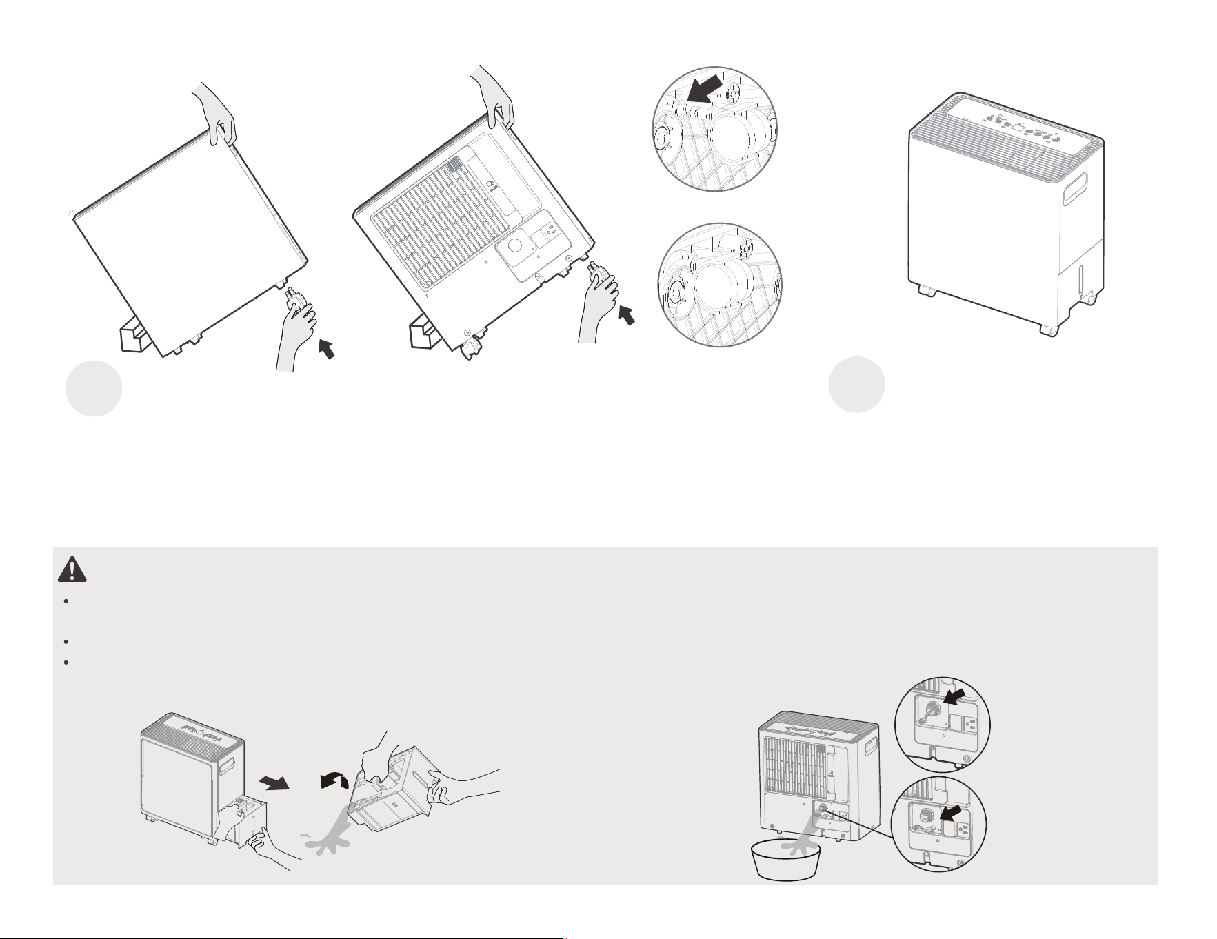
Step 2
WARNING: If you decide to install the castors AFTER the dehumidifier has already been in use
Take out the bucket and remove water plug, drain the water as shown in step 1 and step 2, then reinstall the bucket
and water plug before installing casters.
The tilt ngle is not to exceed 30 degrees when installing casters, and all casters MUST BE installed within 5 minutes.
After the castor installation is complete, set the unit upright and rest for 30 minutes before starting the unit.
Step 1
4
Leave the unit standing
before use
Tilt the unit on its side
and hold it with one
hand, then insert two
casters
Rotate the unit and hold
it with one hand, then
insert the other two casters
Before inserting
Correct insertedly
up for
16
3
half an hour
a
2.TIMER Function
Auto start setting
Press the timer button to initiate the Auto start and Auto stop function, in conjunction with the UP and DOWN buttons.
1. hen the unit is off, press the timer button to activate the Auto start time.
2. Press or hold the UP or DOWN button to change the Auto start time by 0.5 hour increments, up to 10 hours,
then at 1 hour increments,
up to
24
hours.
1.POWER ON/OFF button
Wireless button
1.Press and hold the POWER button for 3 seconds to initiate the Wireless connection mode. The LED DISPLAY shows ’AP’ to indicate you can
set up the wireless connection.
2.If connection
is successful within 8 minutes, the unit will exit Wireless connection mode automatically and the Wireless indicator illuminates
and the unit enters the previous function. If connection fails within 8 minutes, the unit exits the Wireless connection mode automatically
NOTE: When the unit is connecting to the Internet, the light will flicker in white. When the unit has connected
to the Internet, the white light will stop flickering.
Get to know your features
Operation Display
NOTE
Control Panel Features
The following control panels are for explanation purpose only. The control panel of the unit you purchased may be slightly
different according to the models. Your machine may not contain some indicators or buttons. The actual shape will remain
the same.
4
15 7
2 3
6
17
MShield
MShield
W
change the Auto stop
time by 0.5 hour
increments, up to 10 hours, then at 1 hour
increments, up to 24 hours.
3. The selected time will register in 5 seconds
and the system will
automatically revert back to
display the
The control will count down the time remaining
until stop.
NOTE: The timing can be adjusted to increase or decrease
by 24 hours. After the TIMER setting is complete, you can
press the button again to check the TIMER setting status.
After the TIMER setting is complete, you can cancel it by
setting the set time to 0.0.
3. MODE Function
30~50cm
Wet clothes
30~50cm
Airflow
Allow 30~50cm of distance
on the top and right side of
the unit the wet clothes.
2.
3.Make sure to direct airflow
at the wet clothes.
4.
4. UP and DOWN buttons
Humidity Set Control buttons
TIMER Set Control buttons
The humidity level can be set within a range of 35% RH(Relative
Humidity) to 85%RH(Relative Humidity) in 5% increments.
Press the UP and DOWN buttons to set the Auto start and Auto stop
time from 00:00 to 24:00.
5. FAN speed Function
Press the button to select fan speed in the following setting:
Low → High → Low...
NOTE: The fan speed indicator light illuminates under
18
For best results, please ring
out excess moisture from
the clothes before using
the dryer mode.
Clothes that are thick and
heavy may not dry as
effectively.
3.
The
selected time
will
register in
5
seconds
from
and the
system
will
automatically
revert back
to display the
The
control will
count down
the
time
remaining
until
start.
Auto
stop
setting
1.
In
the
startup
state,
press the timer button
to
activate the
Auto
stop time.
2.
Press or
hold the
UP
or
DOWN
button
to
Press the button
to select the mode
you
want,
as shown :
Set→
Cont.→
Dryer→Comfort
NOTE:
The humidity setting cannot be
set manually in
Dryer, Cont. and
Comfort mode; The
set
humidity
will be displayed when selected mode is set, and the
ambient humidity will be displayed 5 seconds later.
Set
Dehumidifying
mode(Set)
Press the button
to select the Dehumidifying
mode,
and
adjust the
desired humidity by pressing the UP and DOWN buttons.
NOTE: Humidity can be set from 35%
to 85%, with 5%
adjustment per press.
Continuous dehumidifying mode(Cont.)
Press the button to select the Continuous dehumidifying mode.
Comfort Dehumidifying Mode(Comfort)
Press the button to select the comfort dehumidifying mode.
NOTE:
The unit will automatically control room
humidity in a comfortable range 45%~55% according
to
the room temperature.
Dryer
mode (Dryer)
Press the button to select the Dryer
mode, and the unit will operate in
Continuous dehumidifying and High fan speed mode, in this mode.
NOTE:
For some models, The unit will quit Dryer mode
after a maximum 10 hours operation.
1. Close
doors and
Windows
while
operating in
this
mode.
ambient humidity.
ambient humidity.
The electronic display will show the ambient humidity and set humidity.
When the timer function is used, the display will show the set time. If
there is an error, the display will show the error code.
Error Codes:
6. Display
ES/EH61 - Evaporator coil temperature sensor error. Unplug the unit
and plug it back in. If the error repeats, call for service.
AS/EH60 - Room temperature sensor error. Unplug the unit and plug it
back in. If the error repeats, call for service.
P2 - Bucket is full of water or bucket is not in right position. Empty the
bucket and replace it in the right position.
EH00 - Indoor EEPROM error. Unplug the unit and plug it back in. If
error repeats, call for service.
The unit will automatically track how long it has been in use. Once the accumulated operation time reaches 250 hours, the check filter light will turn
on, letting you know it is the optimal time to clean the filter. After cleaning and reinserting the filter, press and hold the FAN (reset filter) button for
3 seconds to turn the light off. This will repeat after every 250 hours of use.
motor will continue to run for 30 seconds.
When the Full indicator light illuminates, please empty the bucket and reinstall it correctly.
Then, wait 3 minutes before resuming operation, it can not restart operation in the first 3 minutes. This is to protect the unit.
Operation will automatically start after 3 minutes.
More Features
Check lter eature
If the unit turns o unexpectedly due to power, it will restart with the previous function setting automatically when the power resumes.
Auto-Restart
7.PUMP Function
Press the
to activate the built-in pump function. When using this function, the unit will automatically pump water out until the water
NOTE
• P
Make sure the drain hose is pointed in the direction where you would like to drain the water to.
ump drain hose must be well connected for this mode.
•
•
If the pump indicator light and bucket full indicator light flash simultaneously after pressing the Pump button, the
drain hose may not be installed correctly. See page 23 for instructions on how to properly install the drain hose.
.
loss of
MShield is the air ionizer technology on this unit. Activating the MShield function energizes the ionizer.
19
8.MShield Air Ionizer Function
MShield function and pump function share the same button. Press and hold on the button for 3 seconds to turn the MShield Function on or off.
Fi F
tank is empty. The pump will stop automatically once the water tank is empty.
button
See page 29 for cleaning the filter
.
Eb - For the water pump models, the unit will display "Eb" if the bucket
is not in the right position.
Bucket drainage
Type 1: Type 2:
ater hose drainage
(continuous)
Type 3:
Pump drainage
20
Removing collected water
When your bucket is full.
W
When the unit is o , if the bucket is full, the Full indicator light will turn .
When the unit is on, if the bucket is full, the compressor and the fan turn o
, and the Full indicator light will he digital display shows P2.
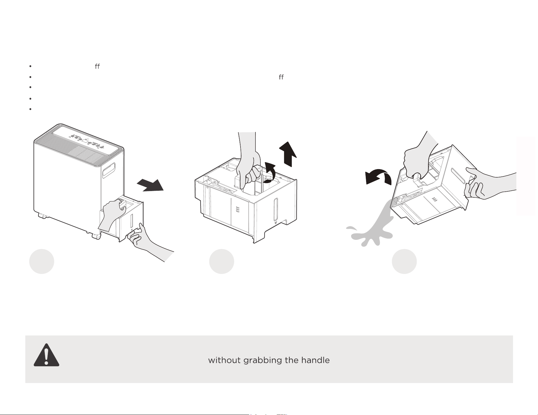
Pull the bucket out halfway, then pull up the handle and lift the bucket slowly vertically to prevent spillage.
the water and replace the bucket. The bucket must be for the dehumidifier to operate.
The appliance will restart when the bucket is restored in its correct position.
Pull the bucket out
halfway.
Pull up the handle and
lift the bucket slowly
vertically.
Type 1
Pour the water out.
Bucket drainage
WARNING:
Do not pull out the whole bucket
or it may cause damage to the bucket
or
on
turn on
Dump correctly installed
21
1
2 3
and
. T
and
personal injury.
Water can be automatically emptied into a floor drain by attaching the unit with a water hose(ld≥Φ5/16", not included) with a female threaded
end(ID:M=1",not included)
When you remove the bucket, do not touch any parts inside of the unit. Doing so may damage the product.
Be sure to push the bucket gently all the way into the unit. Banging the bucket against anything or failing to push it in
securely may cause the unit not to operate.
If the pump hose when you remove the bucket, you must reinstall the pump hose properly to
the unit before
replac the bucket .
When you remove the bucket,if there is some water in the unit you must dry it
the digital display shows Eb.
NOTE
Type 2
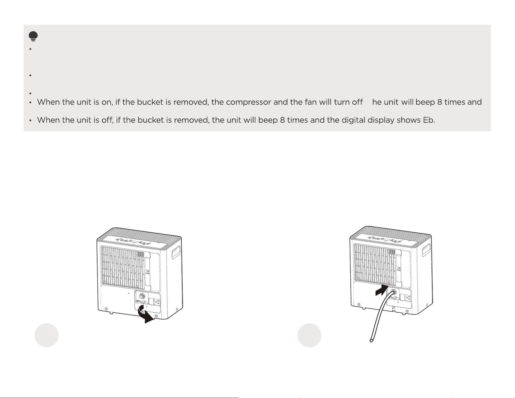
ater hose drainage (continuous)
Remove the water plug. Connect the drain hose.
1
2
ing
becomes disconnected
W
22
Before the water tank begins filling, remove the water plug from the drain outlet and set aside. Then, insert the drain hose through the water
drain outlet. Lead the drain hose to the floor drain or a suitable drainage facility.
with a cloth or towel.
.
T
.
When you remove the water plug, if there is any water in the back drain outlet of the unit you must dry it. Make sure the hose is
.skael on era ereht os eruces
Direct the hose toward the drain, making sure that there are no kinks that will stop the wat
owing. Make sure the water hose is
lower than the drain hose outlet of the unit.
NOTE
The maximum distance and the rise of the hose is 5m from the unit. Exceeding this distance may damage the unit or
cause leaks.
If removing the hose to use in Bucket mode, please reinsert the drain plug to prevent accidental water leakage.
(You still need to press the tightening ring when removing the hose.)
To connect pump drain hose:
Press the tightening ring of drainage joint(as shown
g.1);
Keep pressing the grey ring while pulling out the plug. (as shown
g.2);
Insert the drain hose onto the drainage joint ake sure it is connected well so that it is fully sea ed.
Place the other end of the drain hose in the location you want the water to go to , a water container,
or through a
To remove pump drain hose:
Press the tightening ring of drainage joint.
Pull out the drain hose.
Place the plug back to the joint.
1 2
3 4
basement window to the outdoors.
l
, such as a floor drain
23
Select the desired humidity setting and fan speed on the unit for continuous draining to start.
NOTE: When the continuous draining feature is not being used, remove the drain hose from the outlet, and dry the
the in
in
. M
het
in
water in the continuous drain hose outlet. After drying, make sure to reinstall the water plug.
Pump drainage
Type 3

24
APP INSTRUCTIONS
Specification of Wireless Module
Precautions
App Compatibility:
- The app is available for both iOS and Android, however older versions may no longer be compatible. Please keep the app updated with the
latest version. Midea makes no guarantee of compatibility and is not responsible for issues arising as a consequence thereof.
Wireless Security:
- The Smart Kit supports the following security protocols: WPA-PSK / WPA2-PSK / WPA3-SAE
- It may be used with or without encryption although encryption is strongly recommended
Connectivity:
- Network issues may occasionally cause timeouts. The unit display and the app may become unsynchronized but this will resolve itself when
the network is restored.
- Should the network remain unavailable, it might be necessary to run the configuration process again.
- Change in the wireless network will require reconfiguration of the device.
Configuration:
- The actual network configuration process may vary slightly from the manual.
- Please check the service website for more information.
Model: US-SK105 Dimensions: ).ni( 2.0 x 9.0 x 6.1
Operation Temperature: 0°C - 45°C / 32°F - 113°F
Antenna Type: Printed PCB Antenna
Operation Humidity: 10% - 85%
Frequency: WLAN 2400-2483.5 MHz
Power Input: DC 5V/500 mA
Maximum Transmitted Power: <20 dBm Max
25
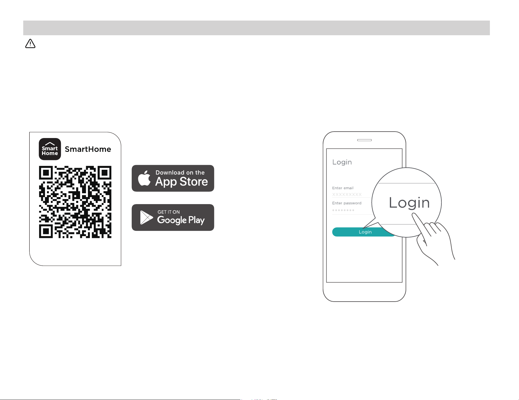
Using the SmartHome App
Step 1: Download the SmartHome app
Ensure that your mobile phone is connected to the wireless network. Bluetooth must be turned on. The device must also be powered up.
Scan the QR code below to download the SmartHome
app from app store or search for it directly on the Google
Play Store or Apple's App Store.
Step 2: Log in
Open the SmartHome app. Log in directly if you have an
existing SmartHome account or create a new account.
Alternatively, you can also use a 3rd party login platform.
Download the app
& activate product
26
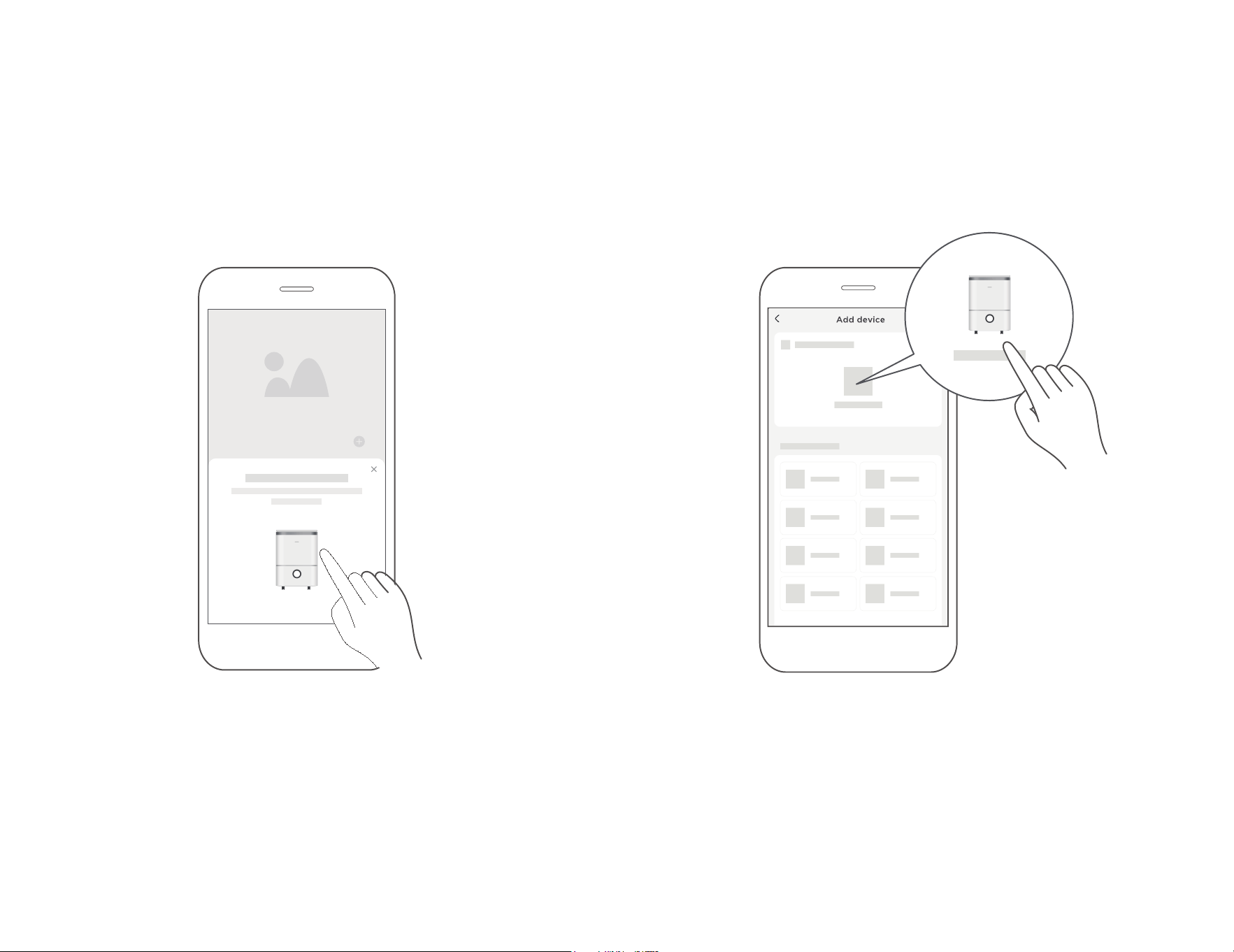
Step 3: Connecting the device
1) When you log in, you may see the message "Smart devices
discovered nearby". Tap to add your device.
2) If no such message appears, proceed as follows:
Tap on "+" and select your device in the list of nearby
available devices.
If your device is not listed, please add your device manually,
first selecting the device category e.g. Dehumidifier.
27
Step 4: Controlling the device
After pairing successfully, a card will be created for the device in
the SmartHome app.
Shortcuts for basic functions will appear on the card such as
changing the humidity or switching the device on or off.
Tapping on the card, will reveal additional features and settings.
The actual design may look different from examples due to
app updates.
3) Follow the steps in the app to connect your device to the
wireless network. If your device fails to connect, follow the
additional instructions in the app.
Add device
SmartHome
Dehumidifier
52%
38%
45%
55% 70%
Target Humidity
Low Med High
Fan Speed
Room humidity 52%
Power

28
Compliance
We, hereby declare that this dehumidifier is in compliance with
the relevant provisions of RE Directive 2014/53/EU. A copy of the
full DoC is attached (Europen Union products only).
This device complies with Part 15 of the FCC Rules and it contains
licence exempt transmitter(s) / receiver(s) that comply with
Innovation, Science and Economic Development Canada’s
licence-exempt RSS(s).
Operation is subject to the following two conditions:
(1) This device may not cause harmful interference;
(2) This device must acceptany interference, including interference
that may cause undesired operation of the device.
Only operate the device in accordance with the instructions
supplied.
Changes or modifications to this unit not expressly approved by
the party responsible for compliance could void the user's
authority to operate the equipment
This device complies with FCC radiation exposure limits set forth
for an uncontrolled environment. In order to avoid the possibility
of exceeding the FCC radio frequency exposure limits, human
proximity to the antenna shall not be less than 20cm (8 inches)
during normal operation.
NOTE:
This equipment has been tested and found to comply with the
limits for a Class B digital device, pursuant to part 15 of the FCC
Rules. These limits are designed to provide reasonable protection
against harmful interference in a residential installation. This
equipment generates, uses and can radiate radio frequency
energy and, if not installed and used in accordance with the
instructions, may cause harmful interference to radio
communications. However, there is no guarantee that interference
will not occur in a particular i nstallation. If this equipment does
cause harmful interference to radio or television reception, which
can be determined by turning the equipment off and on, the user
is encouraged to try to correct the interference by one or more
of the following measures:
· Reorient or relocate the receiving antenna.
· Connect the equipment into an outlet on a circuit different from
that to which the receiver is connected.
· Consult the dealer or an experienced radio/TV technician for
help.
Wireless module models:
US-SK105:
FCC ID: 2ADQOMDNA21
IC: 12575A-MDNA21
()
()
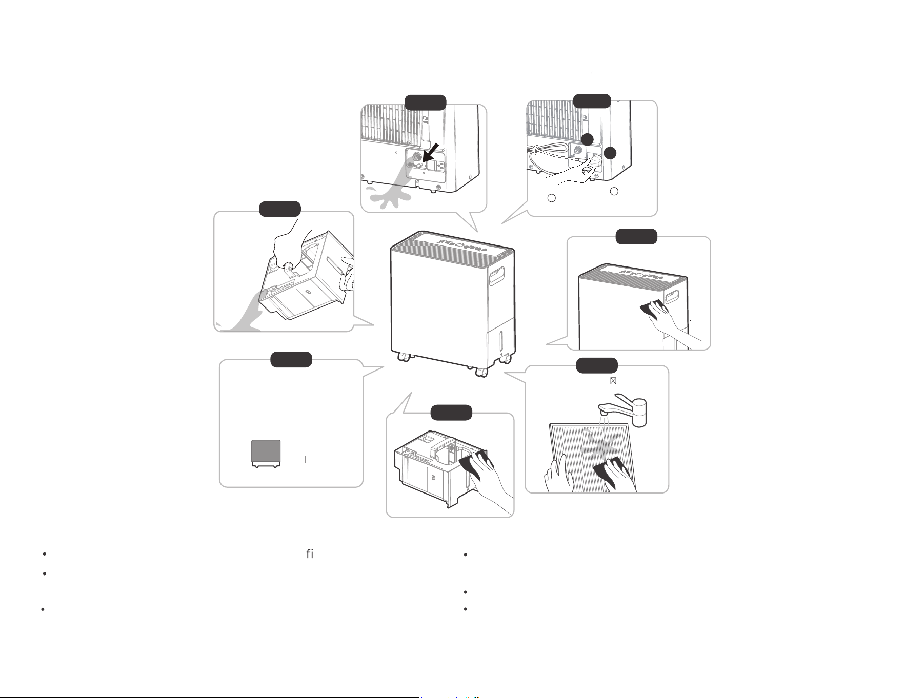
Clean the Grille and Case
Care and Maintenance
Use water and a mild detergent. Do not use bleach or abrasives.
Do not splash water directly onto the main unit. Doing so may cause an electrical shock, cause the insulation to deteriorate, or cause the unit to rust.
The air intake and outlet grilles get soiled easily, so use a vacuum attachment or brush to clean.
Every few weeks, clean the bucket to prevent growth of mold, mildew and bacteria.
Partially fill the bucket with clean water and add a little mild detergent. Swish it around in the bucket, empty and rinse.
Note: Do not use a dishwasher to clean the bucket. After clean , the bucket must be in
place and securely seated for the dehumidifier to operate.
CAUTION
DO NOT operate the dehumidifier without r because dirt and lint will clog it and reduce performance.
Clean the ucket
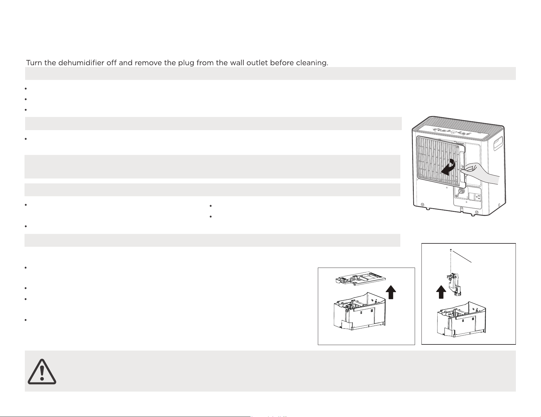
Remove the filter every two weeks based
on normal operating conditions.
To remove the filter, pull filter outwards.
Wash the filter with clean water then dry.
Re-install the filter.
Clean the ir lter
How to clean & your product.
a
Clean the pump filter every two weeks based on normal operating conditions.
Take out the water bucket from the unit and remove the bucket top cover. (as
shown fig.3)
Remove the screw as shown fig.4 .
Take out the pump drainage structure and clean the filter at the b tto
of the hose.
Reinstall the filter and pump drainage structure to the water bucket.
Clean the ump lter
Remove
the screw
Fig. 4
Fig. 3
care for
ing
29
B
A Fi
P Fi
in
in
mo
the filte
Wrap the cord with the power cord buckle.
Properly restore the bucket and place the unit in an upright
position.
Cover the unit with a plastic bag.
Store the unit upright in a dry, well-ventilated place.
Clean the main unit, water bucket and air lter.
When not using the unit for long time periods
Step 4
Step5
Step 1
Step 6
Step7
Refer to Care and Maintenance for instruction on steps 4-6.
Remove water from the bucket.
Clean the grille and case.
Store the unit upright in a dry,
Clean the air
lter
Clean the bucket
well-ventilated place.
.
30
Please dry off any excess water that may be present
after removing the bucket.
Step 2
Re-insert the water plug 1 and insert
plug 2 into the the back of the unit
to keep them in place.
Step 3
1
2
Remove water plug to drain any
excess water.
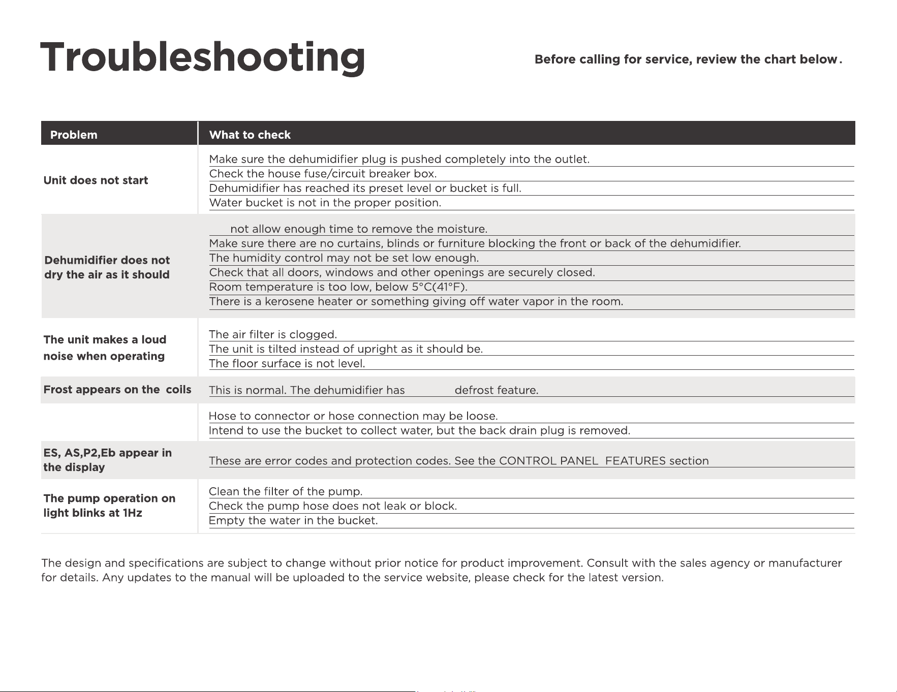
This list includes common occurrences that are not the result of defective workmanship or materials in this appliance.
Did
31
an Auto
Water is leaking onto
the floor
on page 19.
Warranty
32
limited
Warranty
the unit in
33
R
d via our
website https://www.midea.com/us/support.
l