

Sarix Professional 4 Dome Camera Installation Manual
C6725M | 11/22
2
Legal Notices
©2022,PelcoCorporation.Allrightsreserved.PELCO,thePELCOlogo,PELCOaretrademarksof
PelcoCorporation.Othernamesorlogosmentionedhereinmaybethetrademarksoftheirrespective
owners.Theabsenceofthesymbols™and®inproximitytoeachtrademarkinthisdocumentoratallis
notadisclaimerofownershipoftherelatedtrademark.PelcoCorporationprotectsitsinnovationswith
patentsissuedintheUnitedStatesofAmericaandotherjurisdictionsworldwide(seewww.pelco.com).
Unlessstatedexplicitlyandinwriting,nolicenseisgrantedwithrespecttoanycopyright,industrial
design,trademark,patentorotherintellectualpropertyrightsofPelcoCorporationoritslicensors.
Disclaimer
Thisdocumenthasbeencompiledandpublishedusingproductdescriptionsandspecificationsavailable
atthetimeofpublication.Thecontentsofthisdocumentandthespecificationsoftheproductsdiscussed
hereinaresubjecttochangewithoutnotice.PelcoCorporationreservestherighttomakeanysuch
changeswithoutnotice.NeitherPelcoCorporationnoranyofitsaffiliatedcompanies:(1)guaranteesthe
completenessoraccuracyoftheinformationcontainedinthisdocument;or(2)isresponsibleforyour
useof,orrelianceon,theinformation.PelcoCorporationshallnotberesponsibleforanylossesor
damages(includingconsequentialdamages)causedbyrelianceontheinformationpresentedherein.
PelcoCorporation
www.pelco.com
C6725M
Revision:1-EN
20221122

Sarix Professional 4 Dome Camera Installation Manual
C6725M | 11/22
3
Table of Contents
LegalNotices 2
Disclaimer 2
RegulatoryNotices 5
DisposalandRecyclingInformation 5
Overview 6
CameraBaseFrontView 6
CameraBaseRearView 7
CameraBaseBottomView 8
CoverView,SurfaceMount 8
MountingAdapterView,SurfaceMount 9
(Optional)CoverView,In-CeilingMount 9
(Optional)MountingAdapterView,In-CeilingMount 10
(Optional)CoverView,PendantWallMount 10
(Optional)NPTAdapterView,PendantMount 11
(Optional)PendantWallMountView 11
(Optional)PendantWallMountBracketView 12
PreparingtheInstallation 12
Pre-DeploymentIn-BoxConfiguration 12
RemovingtheDomeCover 13
RemovingtheConfigurationCable 13
SurfaceMountInstallation 14
RequiredToolsandMaterials 14
CameraPackageContents 14
InstallationSteps 14
UsingtheSurfaceMountAdapter 14
InstallingtheCameraBasetotheMountingAdapter 18
In-CeilingMountInstallation 20
RequiredToolsandMaterials 20
CameraPackageContents 20
InstallationSteps 20
UsingtheIn-CeilingMountingAdapter 20
InstallingtheCameraBasetotheMountingAdapter 23
PendantMountInstallation 25
RequiredToolsandMaterials 25
PackageContent 25
InstallationSteps 26
MountingtheDomeCameratoaPipe 26
(Optional)MountingtheDomeCameratothePendantWallMount 27

Sarix Professional 4 Dome Camera Installation Manual
C6725M | 11/22
4
InstallingtheCameraBasetotheMountingAdapter 29
ConnectingtotheCamera 31
InitializingaCameraUsernameandPassword 31
(Optional)UsingtheUSBWi-FiAdapter 31
AssigninganIPAddress 32
SettingtheIPAddressUsingtheARP/PingMethod 32
AccessingtheLiveVideoStream 32
AimingtheDomeCamera 33
(Optional)ConfiguringmicroSDCardStorage 34
(Optional)InstallingtheMicrophoneAccessory 35
InstallingtheDomeCover 36
ZoomingandFocusingtheDomeCamera 37
ConfiguringtheCamera 37
ConnectingtoPowerandExternalDevices 37
ConnectionStatusLEDIndicator 39
TroubleshootingNetworkConnectionsandLEDBehavior 39
RemovingtheDomeCamerafromtheMountingAdapter 40
ResettingtoFactoryDefaultSettings 40
ForMoreInformation 41
PelcoTroubleshootingContactInformation 41
Sarix Professional 4 Dome Camera Installation Manual
C6725M | 11/22
5
Regulatory Notices
Thisdevicecomplieswithpart15oftheFCCRules.Operationissubjecttothefollowingtwoconditions:
(1)thisdevicemaynotcauseharmfulinterference,and(2)thisdevicemustacceptanyinterference
received,includinginterferencethatmaycauseundesiredoperation.
ThisClassBdigitalapparatuscomplieswithCanadianICES-003.
ThisequipmenthasbeentestedandfoundtocomplywiththelimitsforaClassBdigitaldevice,pursuant
toPart15oftheFCCrules.Theselimitsaredesignedtoprovidereasonableprotectionagainstharmful
interferenceinaresidentialinstallation.Thisequipmentgenerates,usesandcanradiateradiofrequency
energyand,ifnotinstalledandusedinaccordancewiththeinstructions,maycauseharmfulinterference
toradiocommunications.However,thereisnoguaranteethatinterferencewillnotoccurinaparticular
installation.Ifthisequipmentdoescauseharmfulinterferencetoradioortelevisionreception,whichcan
bedeterminedbyturningtheequipmentoffandon,theuserisencouragedtotrytocorrectthe
interferencebyoneormoreofthefollowingmeasures:
l
Reorientorrelocatethereceivingantenna.
l
Increasetheseparationbetweentheequipmentandthereceiver.
l
Connecttheequipmentintoanoutletonacircuitdifferentfromthattowhichthereceiveris
connected.
l
Consultthedealeroranexperiencedradio/TVtechnicianforhelp.
ChangesormodificationsmadetothisequipmentnotexpresslyapprovedbyPelcoCorporationor
partiesauthorizedbyPelcoCorporationcouldvoidtheuser’sauthoritytooperatethisequipment.
Disposal and Recycling Information
Whenthisproducthasreachedtheendofitsusefullife,pleasedisposeofitaccordingtoyourlocal
environmentallawsandguidelines.
Riskoffire,explosion,andburns.Donotdisassemble,crush,heatabove100°C(212°F),orincinerate.
European Union:
Thissymbolmeansthataccordingtolocallawsandregulationsyourproductshouldbedisposedof
separatelyfromhouseholdwaste.Whenthisproductreachesitsendoflife,takeittoacollectionpoint
designatedbylocalauthorities.Somecollectionpointsacceptproductsforfree.Theseparatecollection
andrecyclingofyourproductatthetimeofdisposalwillhelpconservenaturalresourcesandensurethat
itisrecycledinamannerthatprotectshumanhealthandtheenvironment.
Sarix Professional 4 Dome Camera Installation Manual
C6725M | 11/22
6
Overview
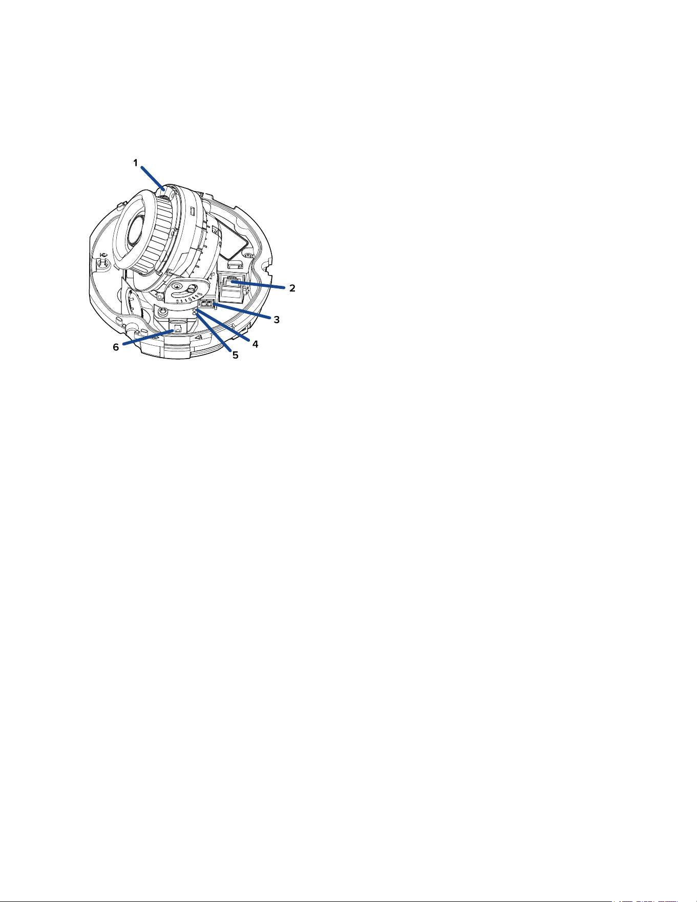
Camera Base Front View
1. IR Illuminator
ProvidessceneilluminationintheIRspectrum.
OnlyavailableonIRmodels.
2. Ethernet port
AcceptspowerandEthernetconnectiontothenetwork.Servercommunicationandimagedata
transmissionalsooccuroverthisconnection.
ThecameracaneitherbepoweredbyPoweroverEthernet(PoE)or12VDCAux.
3. Power connector block
Acceptsaterminalblockwitha12VDCAuxconnection.
OnlyrequiredwhenPoweroverEthernetisnotavailable.
4. Link LED indicator
AmberLEDindicatesifthereisanactiveconnectionintheEthernetport.
5. Connection status LED indicator
GreenLEDprovidesinformationaboutdeviceoperation.Formoreinformation,seeConnection
Status LED Indicator.
6. microSD card slot
AcceptsamicroSDcardforonboardstorage.Formoreinformation,see (Optional) Configuring
microSD Card Storage.
Sarix Professional 4 Dome Camera Installation Manual
C6725M | 11/22
7
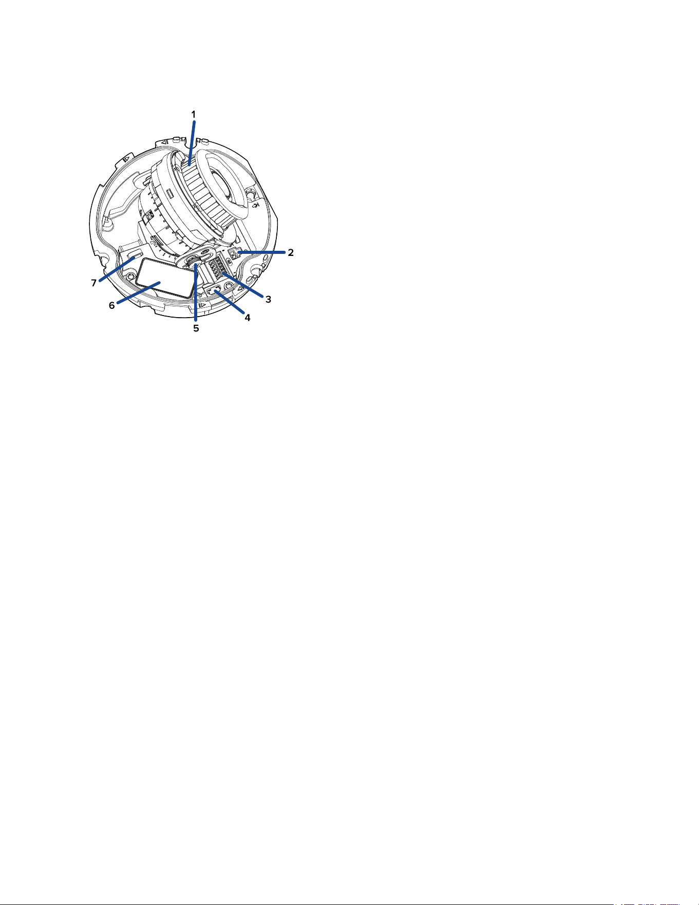
Camera Base Rear View
DisplayedIRilluminatorsonlyavailableon-IRmodels.
1. Azimuth control
Providescontroloftheimageangle.
2. Microphone port
ProvidesconnectiontotheMicrophoneaccessory(ACMICR-1001).Indoormodelsonly.
3. I/O connector block
Providesconnectionstoexternalinput/outputandaudiodevices.
4. Micro USB port
AcceptsamicroUSBtoUSBadapter.OnlyrequiredwhenusingtheUSBWi-FiAdapter.
5. Tilt lock thumb screw
Providesalockingmechanismfortheimagetiltadjustment.
6. Serial number tag
Deviceinformation,productserialnumberandpartnumberlabel.
7. I/O Cable Management Clip
CliptohelpsecuretheI/Ocableinplace.
Sarix Professional 4 Dome Camera Installation Manual
C6725M | 11/22
8
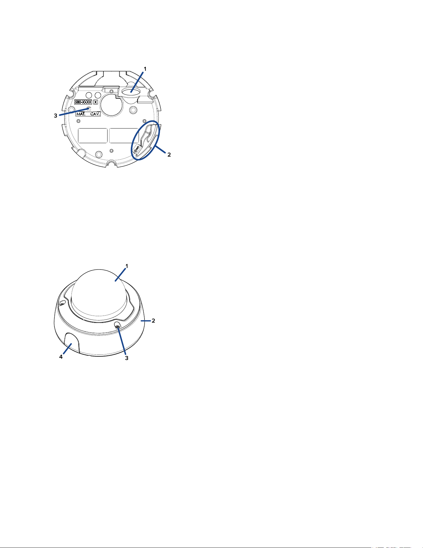
Camera Base Bottom View
1. Cable entry hole
Anentryholeforthecablesrequiredforcameraoperation.
2. Lanyard anchor
Thesafetylanyardattachestotheanchortopreventthecamerafromfallingduringinstallation.
3. Vent
Venttoallowmoisturevaportoescapethesealedhousingandequalizepressure.
Cover View, Surface Mount
1. Dome cover
Vandalresistantdomecover.
2. Surface mount adapter
Usedtomountthedomecameratoawall,ceilingorelectricalbox.
3. Tamper resistant screws
Star-shapedcaptivescrewstofixthedomecovertothemountadapter.
4. Side cable entry cover
Coversthesidecableentryhole.
Sarix Professional 4 Dome Camera Installation Manual
C6725M | 11/22
9
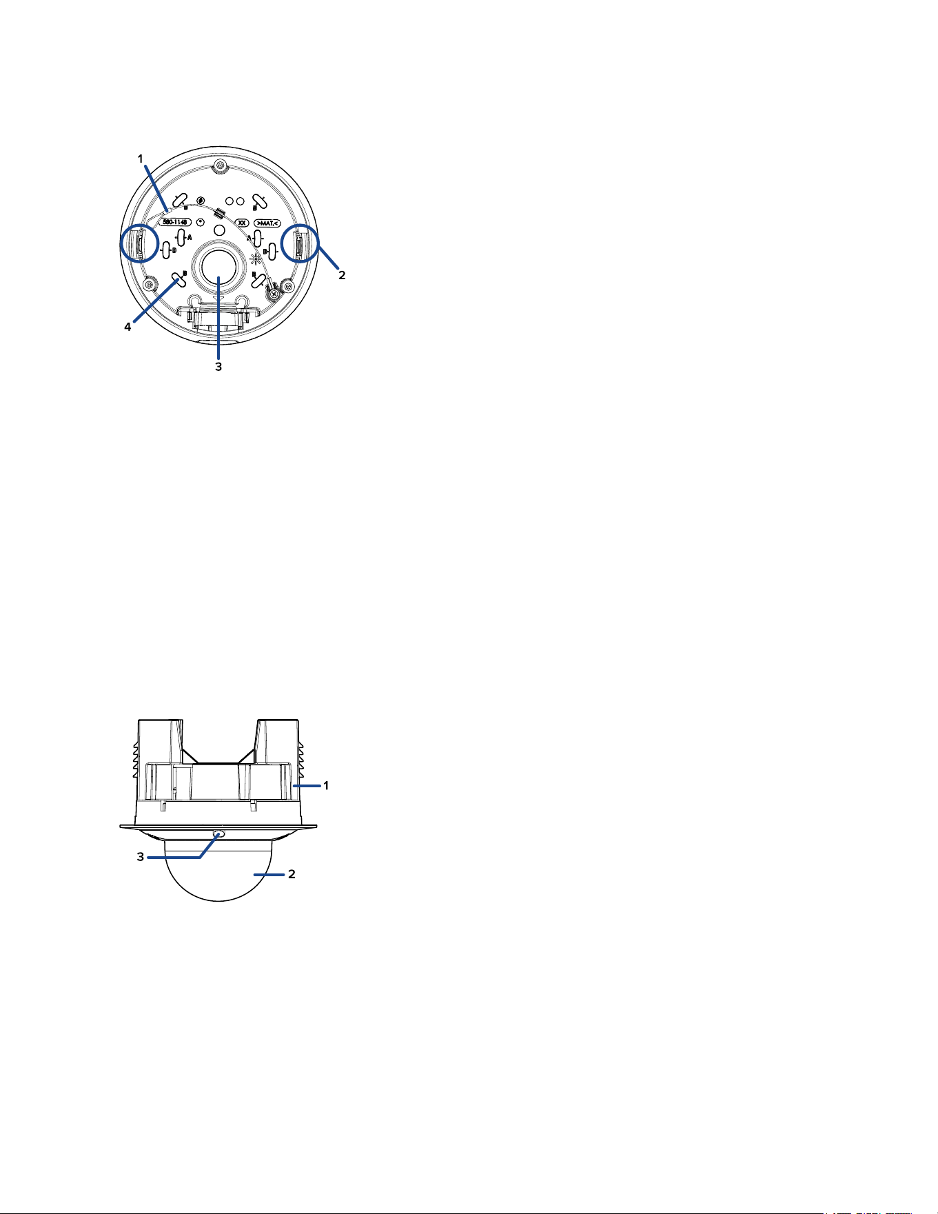
Mounting Adapter View, Surface Mount
1. Lanyard
Connectstothelanyardanchoronthecamerabase.
2. Camera housing clips
Snapstoholdcameramoduleduringinstallation.
3. Cable entry hole
Anentryholeforthecablesrequiredforcameraoperation.
4. Mounting holes
Holesformountingtheadaptertothefollowing:
A—UKstandardsinglegangbox
B—Octagongangbox
D—USstandardsinglegangbox
(Optional) Cover View, In-Ceiling Mount
1. In-ceiling mount adapter
Usedtomountthedomecameratoawall,ceilingorelectricalbox.
2. Dome cover
Vandalresistantdomecover.
3. Tamper resistant screws
Star-shapedcaptivescrewstofixthedomecovertothemountadapter.
Sarix Professional 4 Dome Camera Installation Manual
C6725M | 11/22
10
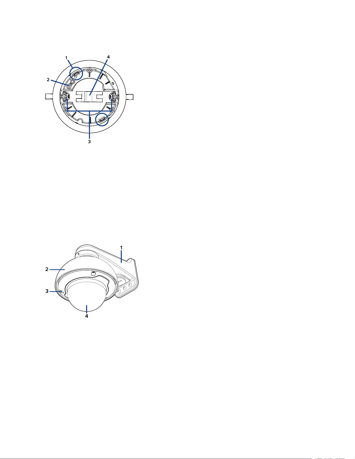
(Optional) Mounting Adapter View, In-Ceiling Mount
1. Camera housing clips
Snapstoholdcameramoduleduringinstallation.
2. Lanyard
Connectstothelanyardanchoronthecamerabase.
3. Clamps
Manuallyadjustableclampsforsecuringthedomecameratotheceiling.
4. Clamp retainer
Usedtoholdtheclampstogetherbeforeinstallation.
(Optional) Cover View, Pendant Wall Mount
1. Pendant wall mount
UsedwiththeNPTadaptertomountthedomecameratoawallinpendantinstallations.
2. NPT adapter
UsedtomountthedomecameratoNPTpipes.
3. Tamper resistant screws
Star-shapedcaptivescrewstofixthedomecovertothemountadapter.
4. Dome cover
Vandalresistantdomecover.
Sarix Professional 4 Dome Camera Installation Manual
C6725M | 11/22
11
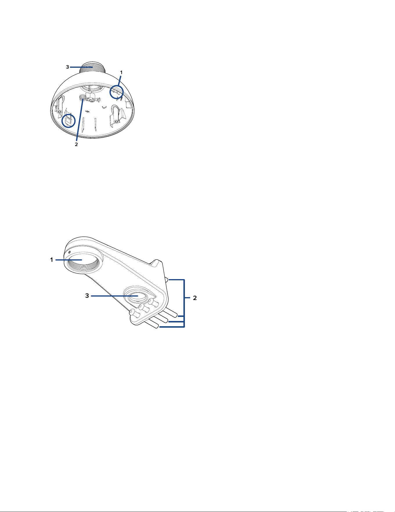
(Optional) NPT Adapter View, Pendant Mount
1. Camera housing clips
Snapstoholdcameramoduleduringinstallation.
2. Lanyard
Connectstothelanyardanchoronthecamerabase.
3. 1-1/2” NPT thread mount
Standardmale1-1/2"NPTthreadmountformountingthedomecameratoapoleorbracket.
(Optional) Pendant Wall Mount View
1. 1-1/2” NPS thread mount
FemaleNPSthreadmountforpendantcamerainstallations.
2. Pendant wall mount screws
Screwsforsecuringthependantwallmounttothemountingbracket.
3. NPT pipe entry hole
A3/4”NPTthreadedholeforNPTpipeconduits.
Sarix Professional 4 Dome Camera Installation Manual
C6725M | 11/22
12
(Optional) Pendant Wall Mount Bracket View
1. Bracket mounting holes
Pointsformountingthependantwallmountbrackettoamountingsurface.
Preparing the Installation
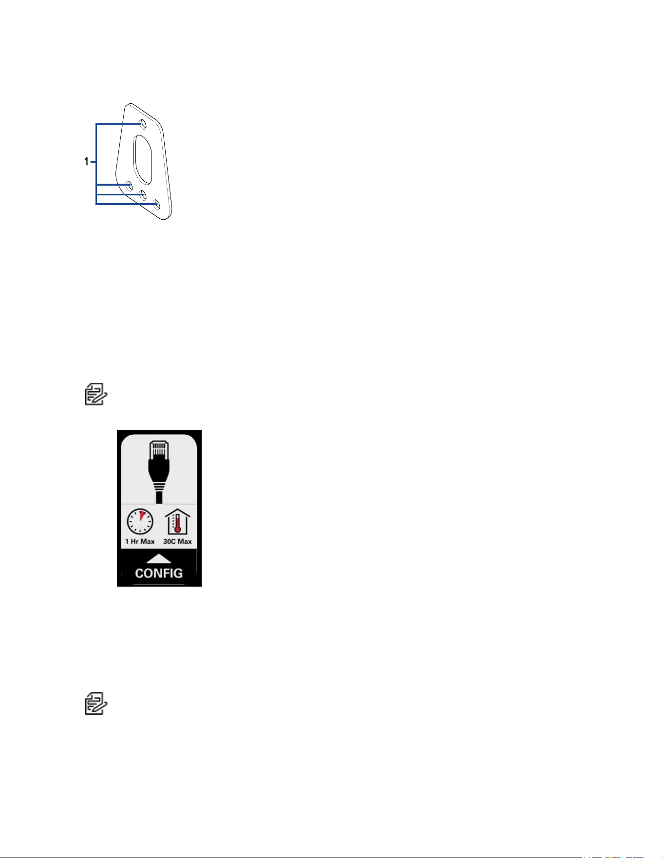
Pre-Deployment In-Box Configuration
ThecameracomesequippedwithanRJ45configurationcablepre-installedforusersthatwantto
configurecamerasettingsbeforeinstallingthecamera.TheRJ45connectorontheconfigurationcableis
accessiblethroughthesmallflaponthesideofthecameraboxforeasyconfigurationbeforeunpacking
thecamera.
Note:Themaximumrecommendeddurationofin-boxconfigurationis1hour.Themaximum
recommendedambienttemperatureis30°C(86°F).
1. Locateandopentheflaponthesideofthecamerapackaging.LookfortheConfiglabel.
2. ConnectanetworkcabletotheRJ45plugontheconfigurationcable.Thenetworkcablemust
providePoE.IEEE802.3afClass3,topowerthecameraduringconfiguration.
3. ConnecttothecamerausingtheCameraConfigurationTool,orthecamera'swebbrowser
interfacetoconfigurethecamera'ssettings.Formoreinformationaboutconnectingtothe
camera,seeAssigning an IP Address.
4. Onceyouhavefinishedmakingconfigurationchanges,unplugthenetworkcable.
Note:Becarefulwhenhandlingthecameraafterconfiguringitinsidethepackaging.Thecamera
maybehotwhenhandlingitorremovingfromthepackagingimmediatelyafterin-box
configuration.
Sarix Professional 4 Dome Camera Installation Manual
C6725M | 11/22
13
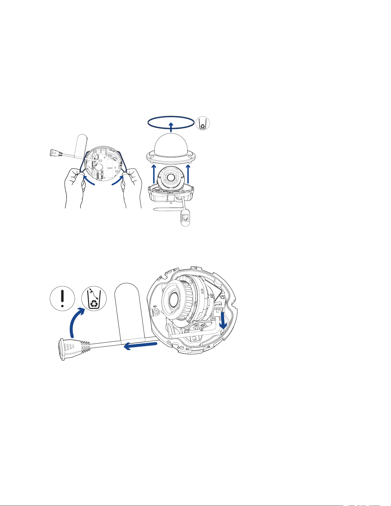
Removing the Dome Cover
Becarefulnottoscratchortouchthedomebubble.Theresultingmarksorfingerprintsmayaffectthe
overallimagequality.Keeptheprotectivecoversontheoutsideofthedomebubbleuntiltheinstallation
iscomplete.
l
Removethedomecoverbyreleasingtheelasticstrapholdingthedomecovertothecamera
base.
Removing the Configuration Cable
Removetheconfigurationcablebypushingdownontheconnector'stabandpullingitoutoftheport.
Next,pullthecordoutthroughthecableentryhole.Thiscablecanbediscarded.

Sarix Professional 4 Dome Camera Installation Manual
C6725M | 11/22
14
Surface Mount Installation
Required Tools and Materials
Thefollowingtoolsarerequiredtocompletetheinstallationbutarenotincludedinthepackage:
l
No.2Phillipsscrewdriver—forattachingcameratoanelectricalboxormountingsurface.
Camera Package Contents
Ensurethepackagecontainsthefollowing:
l
PelcoSarixProfessional4DomeCamera(Indoormodels)
o
Mountingtemplatesticker
o
4screwsandanchorsforsolidwalls
o
Surfacemountadapter
o
Cableentrygrommet
o
Sideconduitcover
o
T20Pin-Instar-shapeddriver
l
PelcoSarixProfessional4DomeCamera(Environmentalmodels)
o
Mountingtemplatesticker
o
4screwsandanchorsforsolidwalls
o
Surfacemountadapter
o
Sideconduitcover
o
1/2"Sideconduitplate
o
Conduitgrommet
o
Cableentrygrommet
o
T20Pin-Instar-shapeddriver
Installation Steps
Using the Surface Mount Adapter
Thedomecameraisprovidedwithasurfacemountadapterthatcanbemountedtoawall,ceilingor
electricalbox.
Ifthedomecameraneedstobeinstalledinadifferentway,useoneoftheothermountingadapter
optionsandrefertotheirsectionsinthismanualformoreinformation.
l
In-ceilingmountingadapter(SLSPCIL-1001).Formoreinformation,seeIn-Ceiling Mount
Installation.
l
PendantNPTmountingadapter(SRXP4-PM-1E).Formoreinformation,seePendant Mount
Installation.
o
Pendantwallmountingadapter(WMVE-AW)—mustbeusedwithNPTmountingadapter.
Mounting the Dome Camera Using the Bottom Cable Entry
Performthefollowingstepsiftherequiredcableswillbecomingfrominsidethemountingsurfaceandthe
camerawillbemountedimmediatelyoverthecablehole.Usethisprocedureonsurfacesthatcanbe
easilydrilledinto,andwhenthecablesshouldbekeptoutofsight.
Sarix Professional 4 Dome Camera Installation Manual
C6725M | 11/22
15
Performthefollowingstepstomountthedomecameratoaceilingorwall:
1. Usethemountingtemplatetodrillfourmountingholesintothemountingsurfaceanddrillthe
cableentryhole.
2. Pulltherequiredcablesthroughthecableentryhole.
3. Drivefourscrewstofastenthemountingadaptertotheceilingorwall.
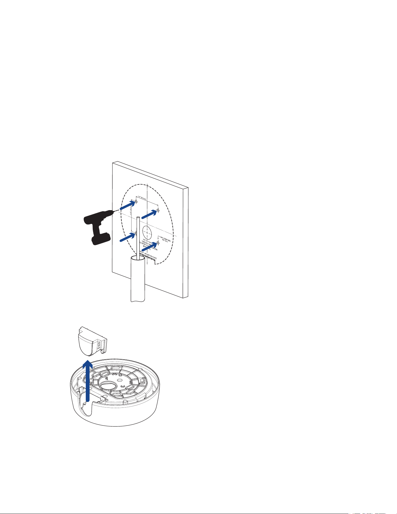
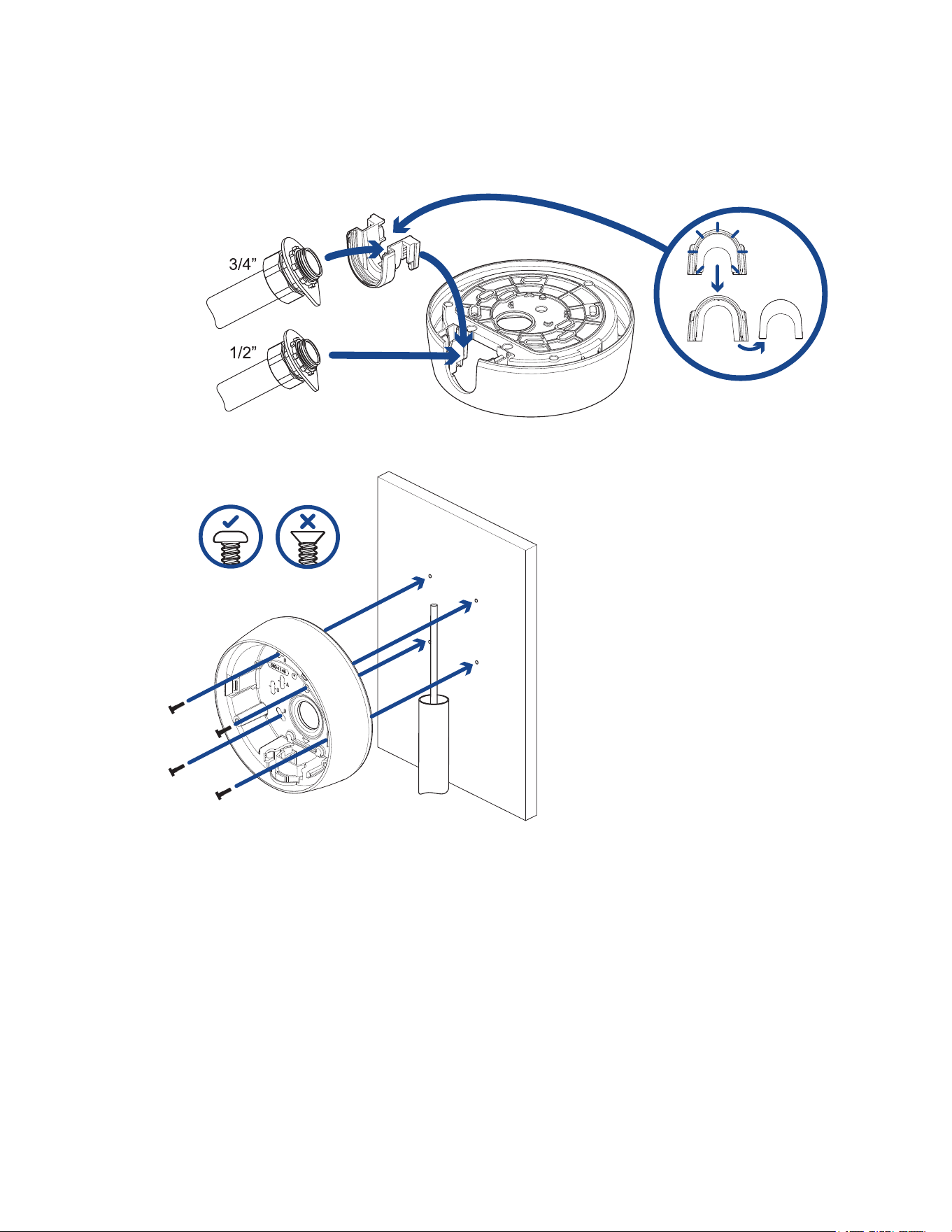
Mounting the Dome Camera Using the Side Cable Entry
Performthefollowingstepsifyouwillbemountingtoasurfacewiththerequiredcablescomingoutofan
externalconduitpipe.Usethisprocedureifthemountingsurfacecannotbeeasilycut,orwhencables
mustbebroughtalongtheoutsideofthemountingsurface.
1. Usethemountingtemplatetodrillfourmountingholesintothemountingsurface.
Makesurethemountingtemplateisalignedtowheretheconduitwillenterthemountingadapter.
2. Pulltherequiredcablesthroughtheconduit.
3. Slidethesidecablecoveroffthemountingadapter.
Sarix Professional 4 Dome Camera Installation Manual
C6725M | 11/22
16
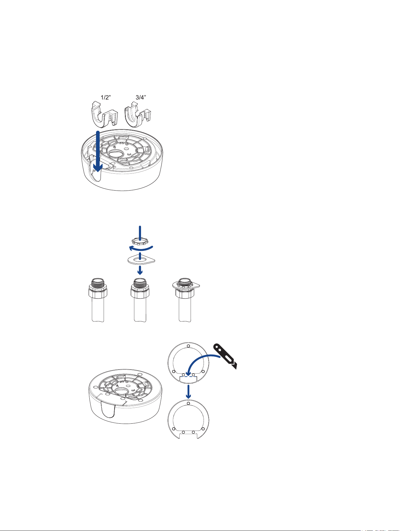
4. Dependingontheconduitused,maketherequiredadjustmentstothesidecableentryhole:
l
Ifyouareusinganinteriorconduit,installthesideconduitcoverontothemountingadapter.
Proceedtostep5.
l
Ifyouareusinganexteriorconduit:
o
Installaconduitplatetoanexternalconduitadapter.Ensuretheplateiscompatiblewith
thesizeofconduitused.
o
Ifyouareinstallinganenvironmentalmodel,youmayneedtocutoffpartoftherubber
gasketonthemountingadaptertomakeroomfortheplate.
Sarix Professional 4 Dome Camera Installation Manual
C6725M | 11/22
17
o
Fora3/4"conduit,removethecenterknockoutpieceonthesideconduitcover.Next,
installthesideconduitcoverontothemountingadapter.
A1/2"conduitwillfitintothemountingadapterwithoutasideconduit.
5. Drive4screwstofastenthemountingadaptertotheceilingorwall.
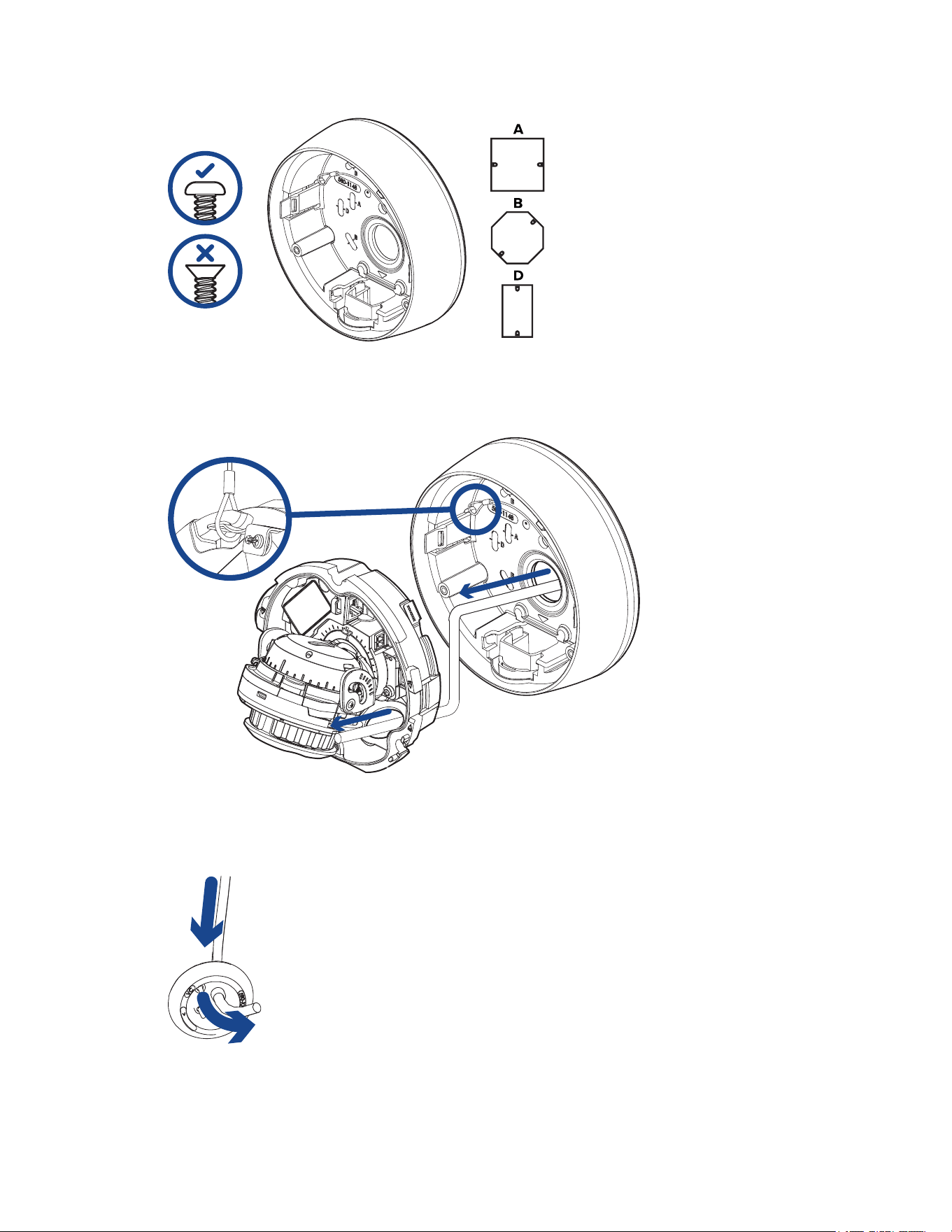
Mounting the Dome Camera to an Electrical Box
Performthefollowingstepsiftherequiredelectricalcomponentsandcableswillbecontainedinan
electricalgangboxinsidethemountingsurface.
1. Pulltherequiredcablesthroughthecableentryhole.
2. Usepanheadscrewstoinstallthemountingadaptertotheelectricalbox.
Selecttheholeconfigurationthatmatchestheelectricalboxshape:
A—UKstandardsinglegangbox
B—Octagongangbox
D—USstandardsinglegangbox
Sarix Professional 4 Dome Camera Installation Manual
C6725M | 11/22
18
Installing the Camera Base to the Mounting Adapter
Afteryouinstallthemountingadapter,mountthecamerabasetotheadapter.
1. Attachthelanyardonthemountingadaptertotheanchoronthecamerabase.
2. PulltheEthernetcablethroughthecableentryholeonthecamerabase.
3. PushtheEthernetcablethroughtheprovidedcableentrygrommet.
Alwaysusetheprovidedcableentrygrommettopreventdustanddebrisfromenteringthe
camera.
Sarix Professional 4 Dome Camera Installation Manual
C6725M | 11/22
19
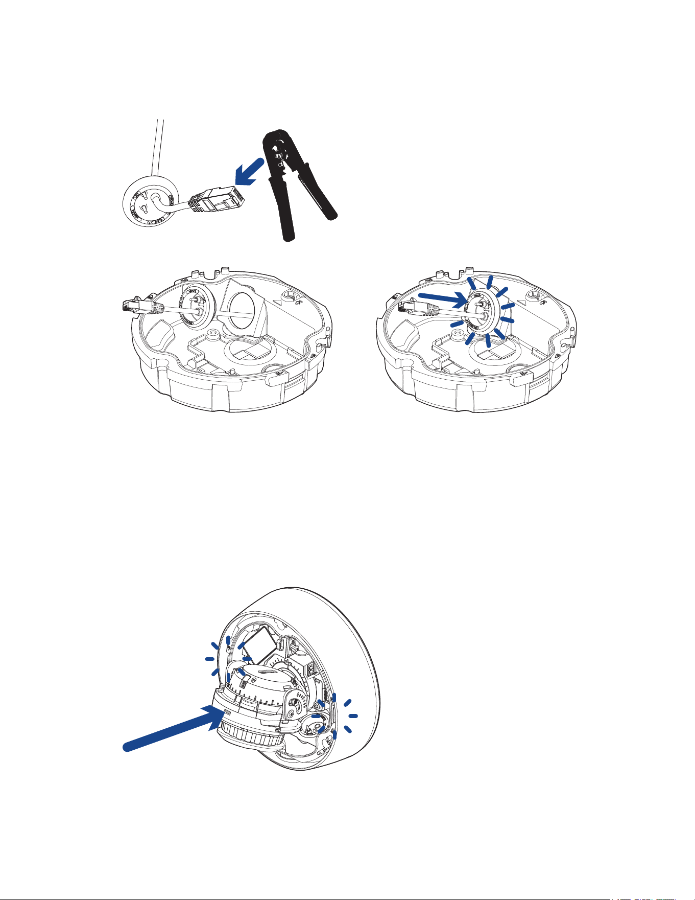
4. CrimptheEthernetcable.Ensurethattheorientationofthecableandgrommetmatchestheone
shownintheimage.
5. Installthegrommetintothecableentryholeonthecamerabase.
Makesurethegrommetissecurelyseatedontheinsideandoutsideofthecableentryhole.Apply
siliconesealanttosealanygapsinthegrommet.
6. Connectthenetworkcabletothecamera'sEthernetport.
TheLinkLEDwillturnononceanetworklinkhasbeenestablished.
7. Ifexternalpower,inputoroutputdevices,oraudiodevicesarepartoftheinstallation(forexample:
doorcontacts,relays,microphone,etc.),connectthedevicestotheI/Oconnectorblock.
Formoreinformation,seeConnecting to Power and External Devices.
8. Alignthearrowonthecamerabasetothesidecableentryholeonthemountingadapterthen
pressthecamerabaseintothemountingadapter.Thecamerabaseclicksintoplaceandisheld
securely.

Sarix Professional 4 Dome Camera Installation Manual
C6725M | 11/22
20
In-Ceiling Mount Installation
Required Tools and Materials
Thefollowingtoolsarerequiredtocompletetheinstallationbutarenotincludedinthepackage:
l
Appropriatetoolforcuttingtheentryholeinthemountingsurface
Camera Package Contents
Ensurethedomecamerapackagecontainsthefollowing:
l
PelcoSarixProfessional4DomeCamera(Indoormodels)
o
T20Pin-Instar-shapeddriver
o
Cableentrygrommet
o
Providedaccessoriesthatarenotrequiredforthisinstallation:
l
Mountingtemplatesticker
l
4screwsandanchorsforsolidwalls
l
Surfacemountadapter
l
Sideconduitcover
l
PelcoSarixProfessional4DomeCamera(Environmentalmodels)
o
T20Pin-Instar-shapeddriver
o
Providedaccessoriesthatarenotrequiredforthisinstallation:
l
Mountingtemplatesticker
l
4screwsandanchorsforsolidwalls
l
Surfacemountadapter
l
Sideconduitcover
l
1/2"Sideconduitplate
Ensurethemountingadapter(SLSPCIL-1001)packagecontainsthefollowing:
l
In-ceilingmountingadapterforaSarixProfessional4DomeCamera
l
Mountingtemplatesticker
Installation Steps
Using the In-Ceiling Mounting Adapter
Ifthedomecameraneedstobeinstalledintoaceiling,youcandiscardthesurfacemountadapterthatis
providedwiththedomecameraandusethein-ceilingmountingadapterinstead(SLSPCIL-1001).
Themaximumsupportedceilingthicknessis32mm(1.25").
Sarix Professional 4 Dome Camera Installation Manual
C6725M | 11/22
21
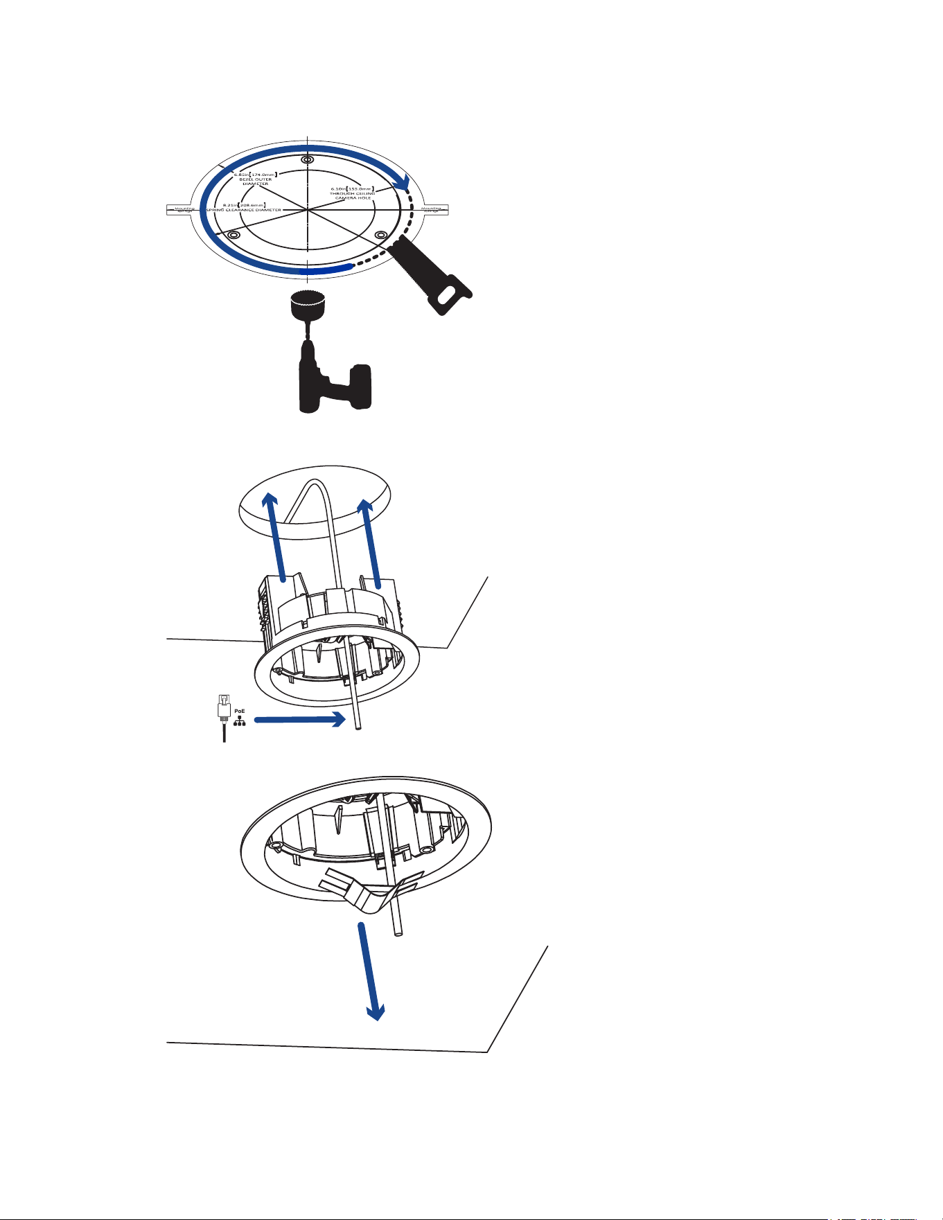
1. Usethein-ceilingmountingtemplatetocutanentryholeforthecameraintotheceiling.
2. Insertthein-ceilingmountingadapterintotheentryholethenpulltherequiredcablesthroughthe
adapter.
3. Pullofftheclampretainerholdingtheclampsinplace.
Sarix Professional 4 Dome Camera Installation Manual
C6725M | 11/22
22
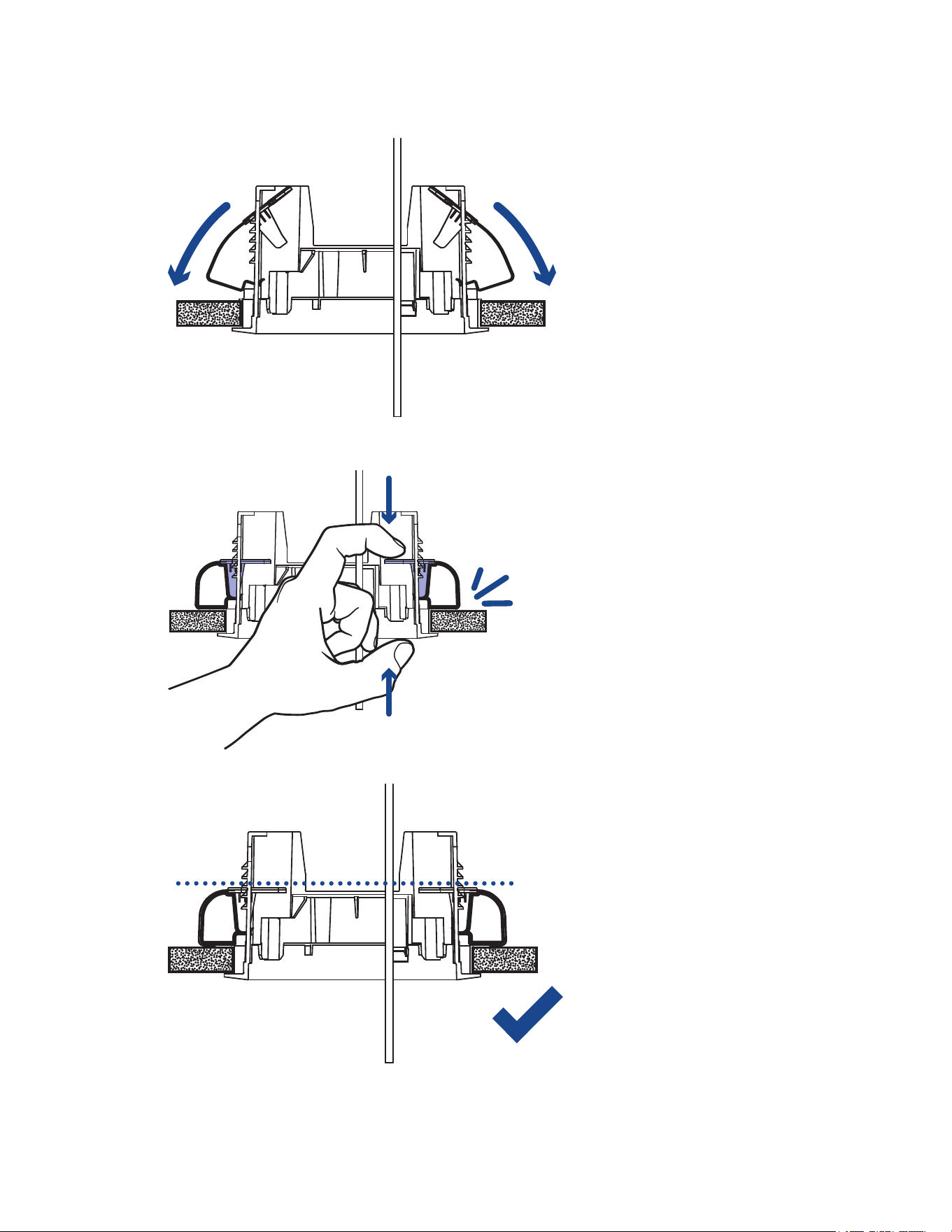
4. Pushtheorangeclamphandlesupsothatthemetalarmsextendoutsidethemountingadapter.
5. Withyourthumbontheoutsideedgeofthemountingadapterandyourforefingerononeofthe
orangeclamphandles,pinchtheclampdownuntiltheclampissecured.
6. Repeatthepreviousstepontheotherside.Makesurebothclampsarelevelandhorizontal.
Sarix Professional 4 Dome Camera Installation Manual
C6725M | 11/22
23
Installing the Camera Base to the Mounting Adapter
Afteryouinstallthemountingadapter,mountthecamerabasetotheadapter.
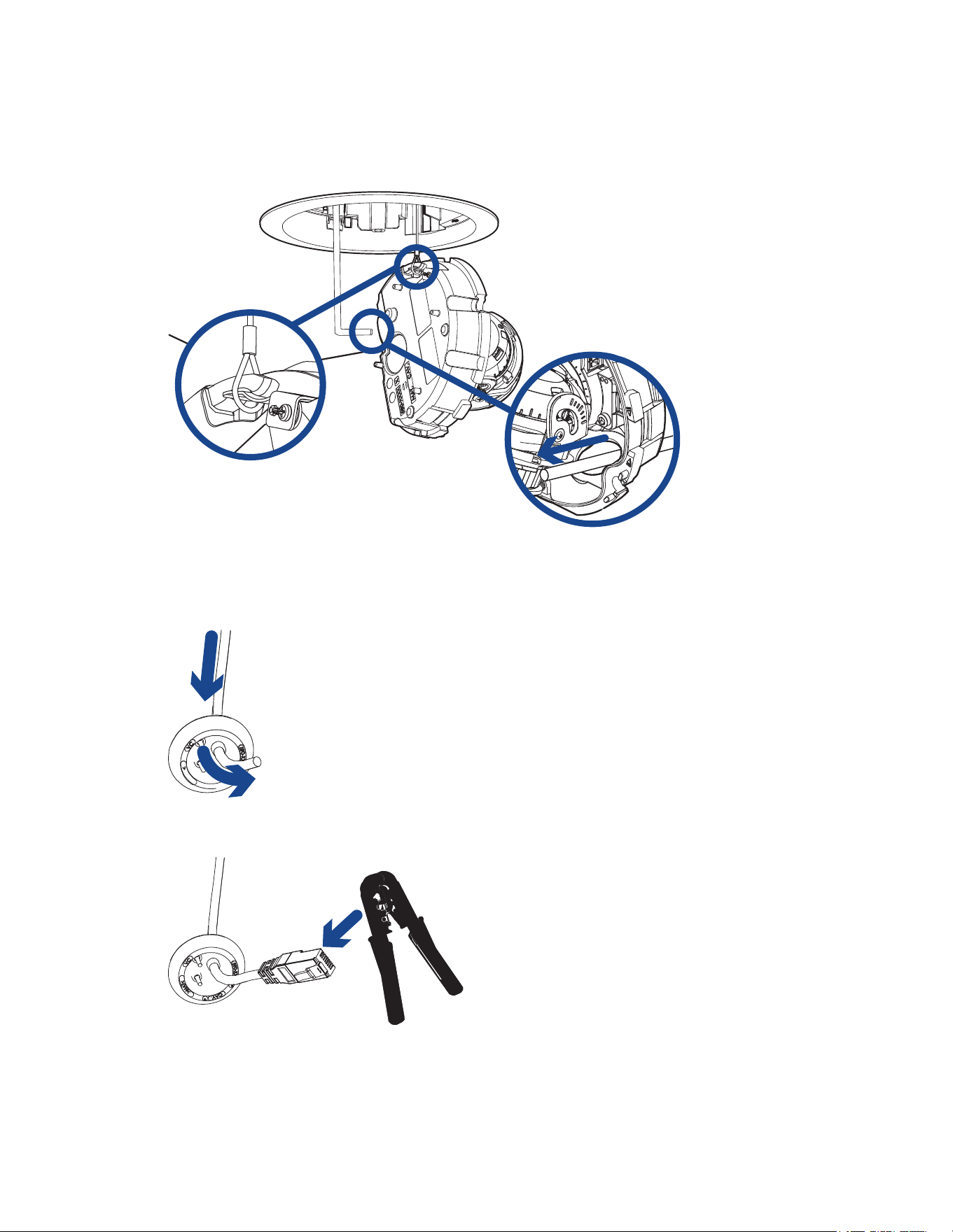
1. Attachthelanyardonthemountingadaptertotheanchoronthecamerabase.
2. PulltheEthernetcablethroughthecableentryholeonthecamerabase.
3. PushtheEthernetcablethroughtheprovidedcableentrygrommet.
Alwaysusetheprovidedcableentrygrommettopreventdustanddebrisfromenteringthe
camera.
4. CrimptheEthernetcable.Ensurethattheorientationofthecableandgrommetmatchestheone
shownintheimage.
Sarix Professional 4 Dome Camera Installation Manual
C6725M | 11/22
24
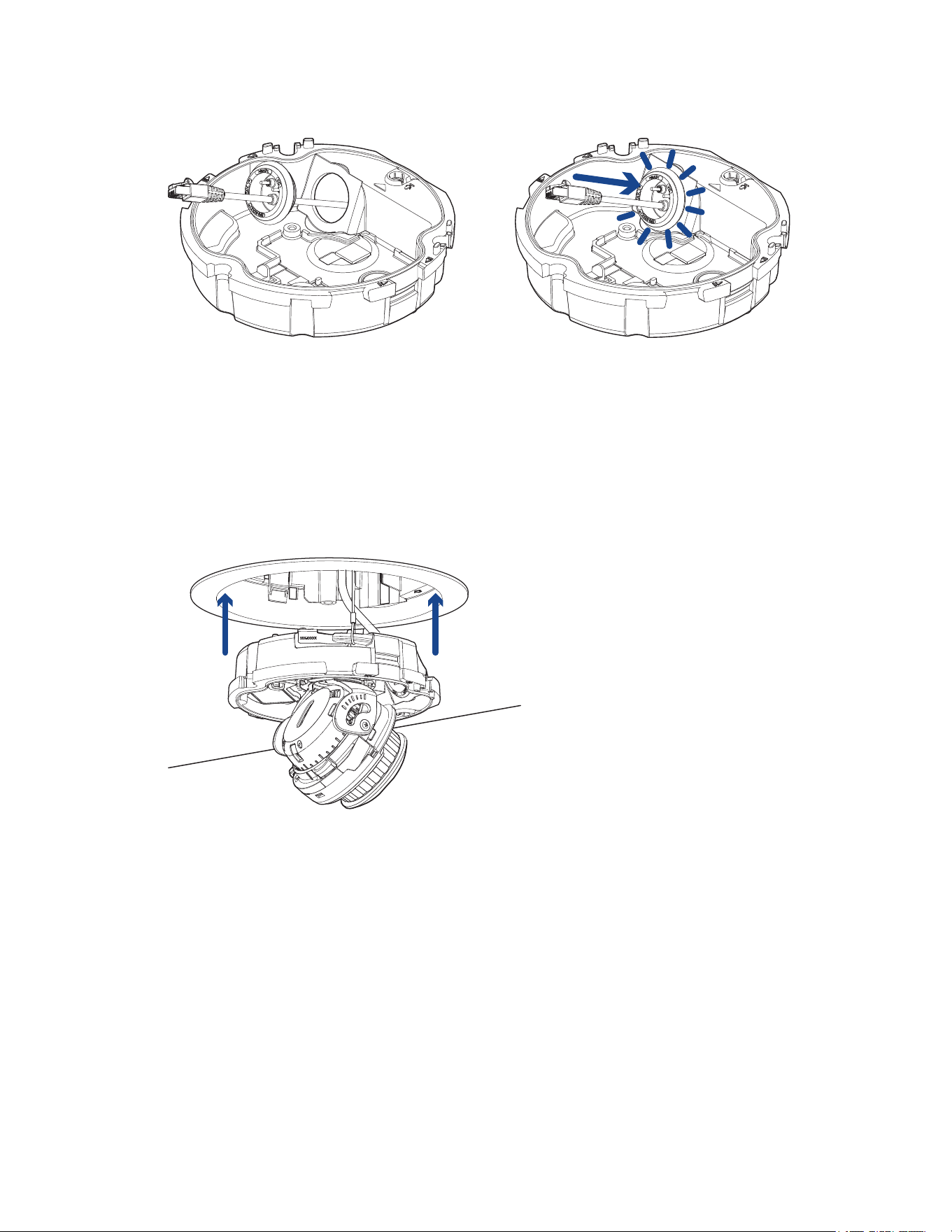
5. Installthegrommetintothecableentryholeonthecamerabase.
Makesurethegrommetissecurelyseatedontheinsideandoutsideofthecableentryhole.Apply
siliconesealanttosealanygapsinthegrommet.
6. Connectthenetworkcabletothecamera'sEthernetport.
TheLinkLEDwillturnononceanetworklinkhasbeenestablished.
7. Ifexternalpower,inputoroutputdevices,oraudiodevicesarepartoftheinstallation(forexample:
doorcontacts,relays,microphone,etc.),connectthedevicestotheI/Oconnectorblock.
Formoreinformation,seeConnecting to Power and External Devices.
8. Alignthearrowonthecamerabasetotheorangearrowonthemountingadapter,thenpressthe
camerabaseintothemountingadapter.Thecamerabaseclicksintoplaceandisheldsecurely.

Sarix Professional 4 Dome Camera Installation Manual
C6725M | 11/22
25
Pendant Mount Installation
Required Tools and Materials
Thefollowingtoolsandmaterialsarerequiredtocompletetheinstallationbutarenotincludedinthe
package:
l
4fasteners(1/4"recommended)—usedforsecuringthewallmounttothemountingsurface.For
moreinformation,refertothePelco WMVE Series Installation Manualincludedwiththewall
mount(WMVE-AW).
l
Screwdriverorwrenchcompatiblewiththeabovefasteners—forattachingthependantwall
mountbrackettothemountingsurface.
l
Wrench,5/64",hexAllen
TheNPTpipe(forpendantpipemountedinstallations)andNPT-femaletoNPT-femaleadapter(for
pendantpipeandwallmountedinstallations)arenotsuppliedbyPelcoandshouldbesourced
separately.However,ifyouareusingtheNPTadapter(SRXP4-PM-1E),thelocknutisincluded.
Package Content
Ensurethedomecamerapackagecontainsthefollowing:
l
PelcoSarixProfessional4DomeCamera(Indoormodels)
o
T20Pin-Instar-shapeddriver
o
Cableentrygrommet
o
Providedaccessoriesthatarenotrequiredforthisinstallation:
l
Mountingtemplatesticker
l
4screwsandanchorsforsolidwalls
l
Surfacemountadapter
l
Sideconduitcover
l
PelcoSarixProfessional4DomeCamera(Environmentalmodels)
o
T20Pin-Instar-shapeddriver
o
Providedaccessoriesthatarenotrequiredforthisinstallation:
l
Mountingtemplatesticker
l
4screwsandanchorsforsolidwalls
l
Surfacemountadapter
l
Sideconduitcover
l
1/2"Sideconduitplate
EnsuretheNPTadapter(SRXP4-PM-1E)packagecontainsthefollowing:
l
NPTadapterfortheSarixProfessional4DomeCamera
l
T20Pin-Instar-shapeddriver
l
Locknut
l
Teflonsealingtape
Sarix Professional 4 Dome Camera Installation Manual
C6725M | 11/22
26
Ifyouarealsoinstallingthependantwallmount(WMVE-AW),ensurethepackagecontainsthe
following:
l
Pendantwallmount
l
11/2"NPTto3/4"NPTadapter
l
3/4"NPTnut
l
Tubeofanti-seizelubricant
l
Wallmountgasket
Installation Steps
Mounting the Dome Camera to a Pipe
Ifthedomecameraneedstobeinstalledtoapipeforapendantinstallation,youcandiscardthesurface
mountadapterthatisprovidedwiththedomecameraandusetheNPTadapter.
Thisprocedurerequiresa1-1/2"NPT-femaletoNPT-femalepipeadapter.Itisrecommendedthatthe
NPTadapterbemountedtoa1-1/2"conduitpipe.
1. PulltherequiredcablesthroughtheNPTconduitpipe.
2. Applythreadsealtapetothepipeandscrewonthe1-1/2"NPTfemaletoNPTfemalepipe
adapter.
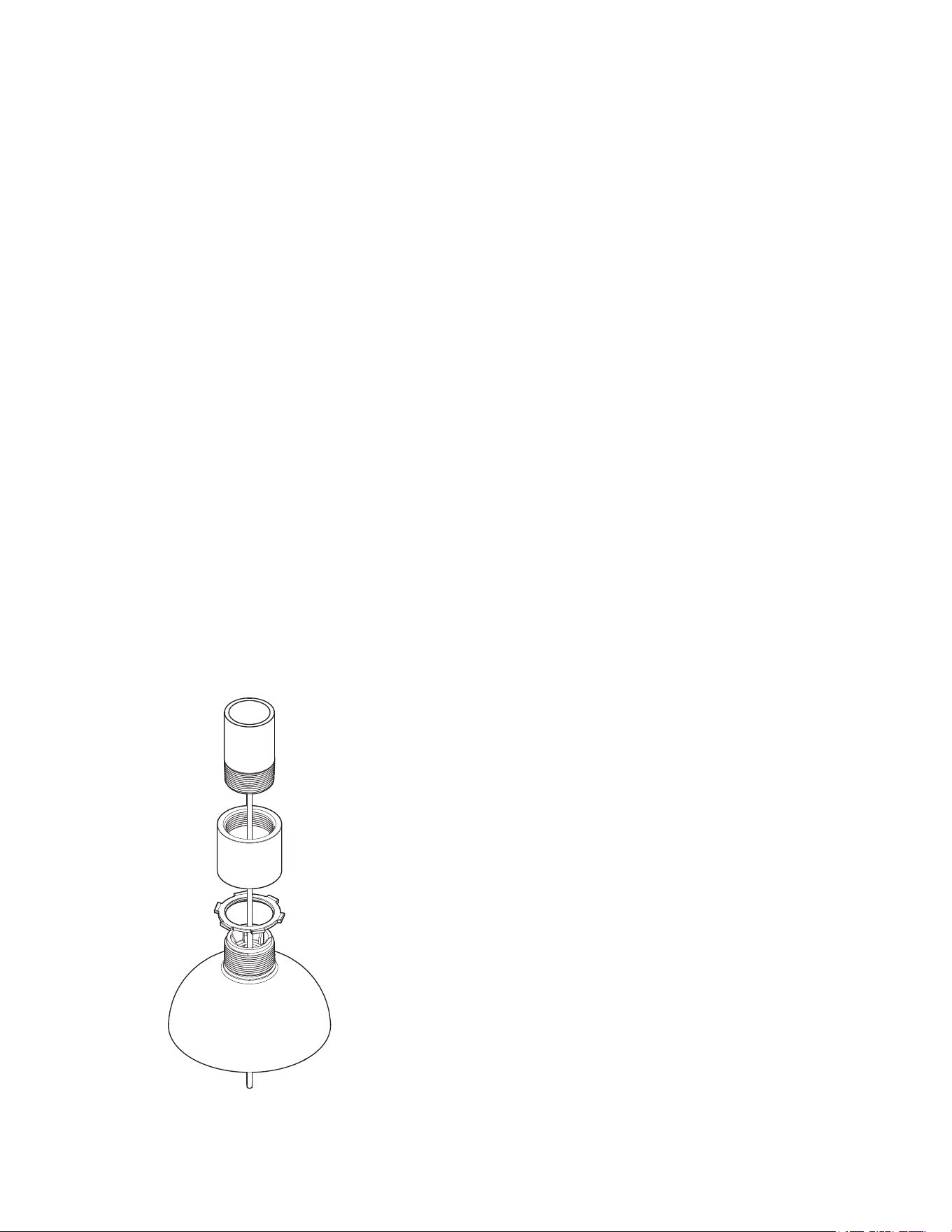
3. ScrewthelocknutontotheNPTadapter.
4. ApplythreadsealtapetotheNPTadapterandscrewitintothepipeadapter.
MakesurethepartsareassembledinthisorderfromNPTconduitpipetocameraadapter:
a. NPTconduitpipe
b. 1-1/2"NPTfemaletofemalepipeadapter
c. Locknut
d. NPTadapter
Sarix Professional 4 Dome Camera Installation Manual
C6725M | 11/22
27
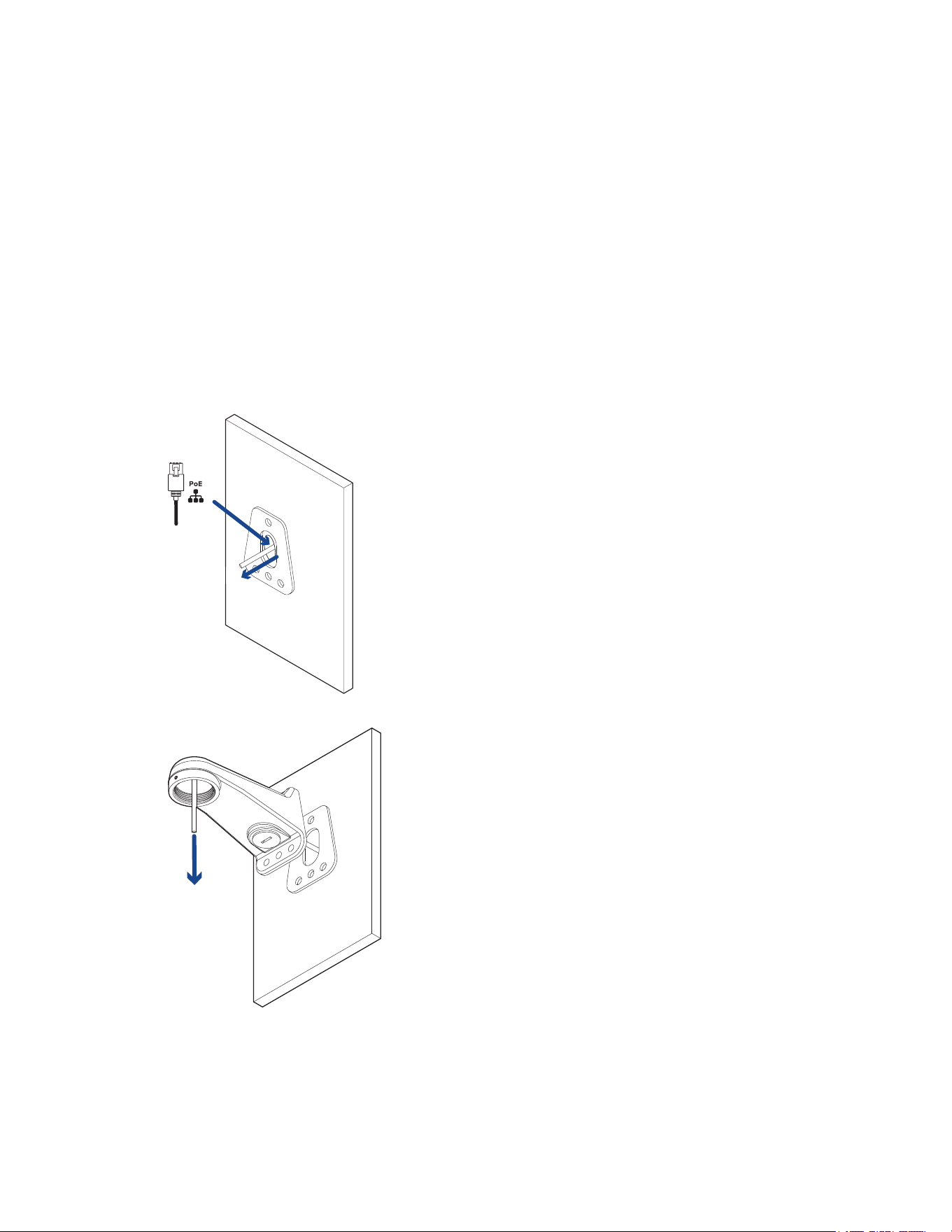
(Optional) Mounting the Dome Camera to the Pendant Wall Mount
Ifthedomecamerawillbeusingthependantwallmount,youwillneedtoinstalltheNPTadapteraswell.
1. Determinewherethecableswillenterthependantwallmount.
l
Ifthecableswillbepulledfrominsidethemountingsurface,usethecableentryholeatthe
rearofthependantwallmount.
l
Ifthecableswillbecomingoutofanexternalconduitpipe,usethe3/4”NPTpipeentryhole
onthebottomofthependantwallmount.
2. Usetheprovidedmountingtemplatetodrillfourmountingholesintothemountingsurface.
l
Ifyouareusingtherearcableentryhole,alsodrillthecableentryholeintothemounting
surface.
3. Placethependantwallmountbracketonthemountingsurface.Pullcablesthroughthewallmount
bracket.
4. Insertthependantwallmountoverthebracketmountingtabs.Pullcablesthroughthearm.
5. Pulltherequiredcablesthroughthepreferredcableentryholeonthependantwallmount.Ifyou
areusingthepipeentryhole,pullthecablesthroughthepipeconduitthenthewallmount.Next,
applythreadsealtapetothepipeconduitandscrewitintothepipeentryhole.
Sarix Professional 4 Dome Camera Installation Manual
C6725M | 11/22
28
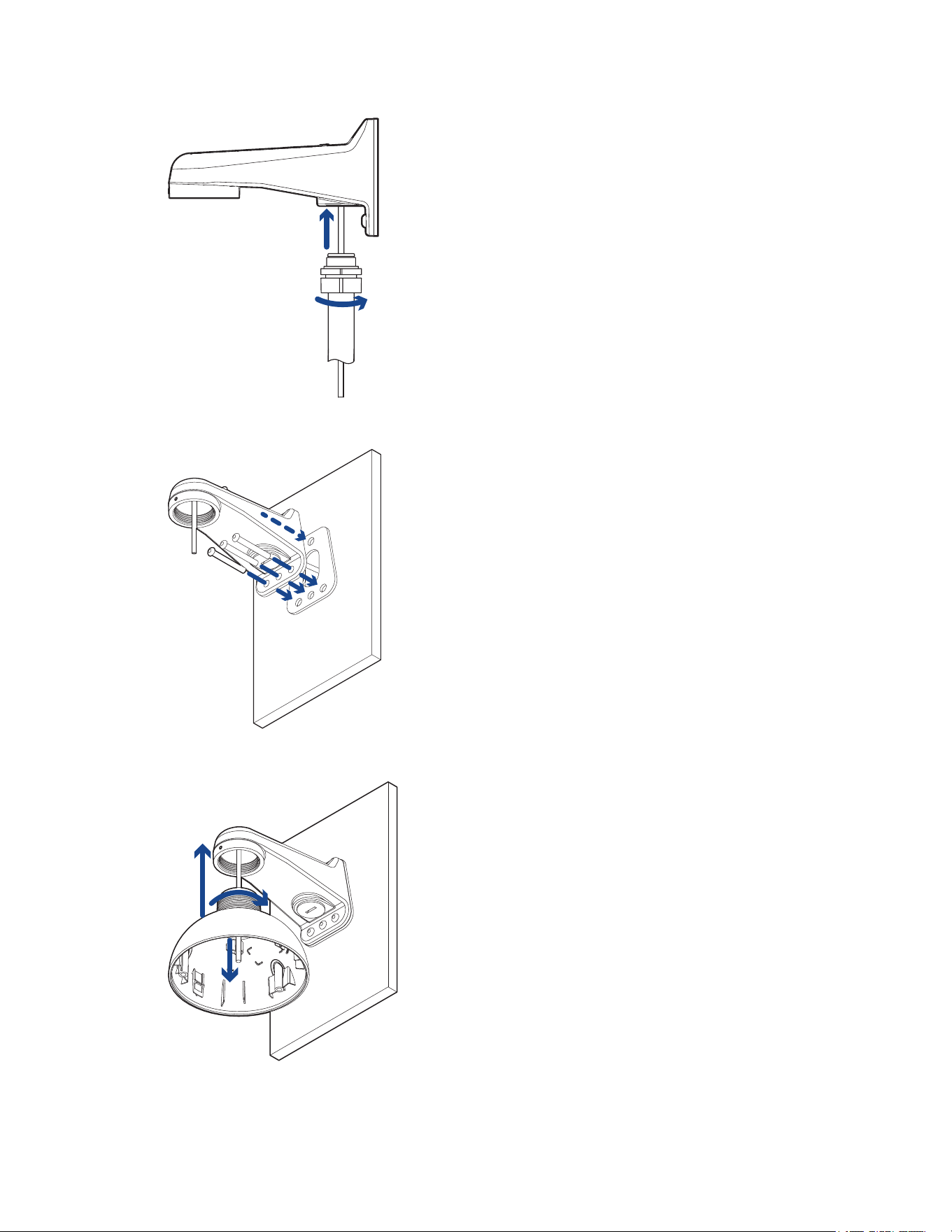
6. Tightenthewallmountscrewswithfourfasteners(1/4"recommended)tosecurethewallmount
tothemountingsurface.
7. ScrewtheNPTadapterintothependantwallmountandtightenit.Usea5/64"hexAllenwrench
(notsupplied)totightenthesetscrewlocatedonthefrontofthewallmount.
Sarix Professional 4 Dome Camera Installation Manual
C6725M | 11/22
29
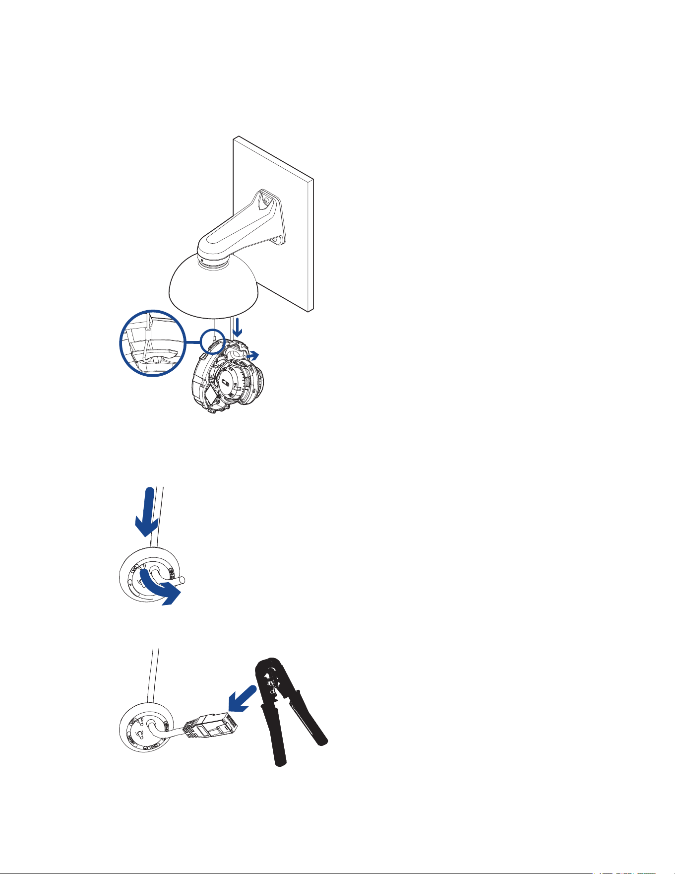
Installing the Camera Base to the Mounting Adapter
Afteryouinstallthemountingadapter,mountthecamerabasetotheadapter.
1. Attachthelanyardonthemountingadaptertotheanchoronthecamerabase.
2. PulltheEthernetcablethroughthecableentryholeonthecamerabase.
3. PushtheEthernetcablethroughtheprovidedcableentrygrommet.
Alwaysusetheprovidedcableentrygrommettopreventdustanddebrisfromenteringthe
camera.
4. CrimptheEthernetcable.Ensurethattheorientationofthecableandgrommetmatchestheone
shownintheimage.
Sarix Professional 4 Dome Camera Installation Manual
C6725M | 11/22
30
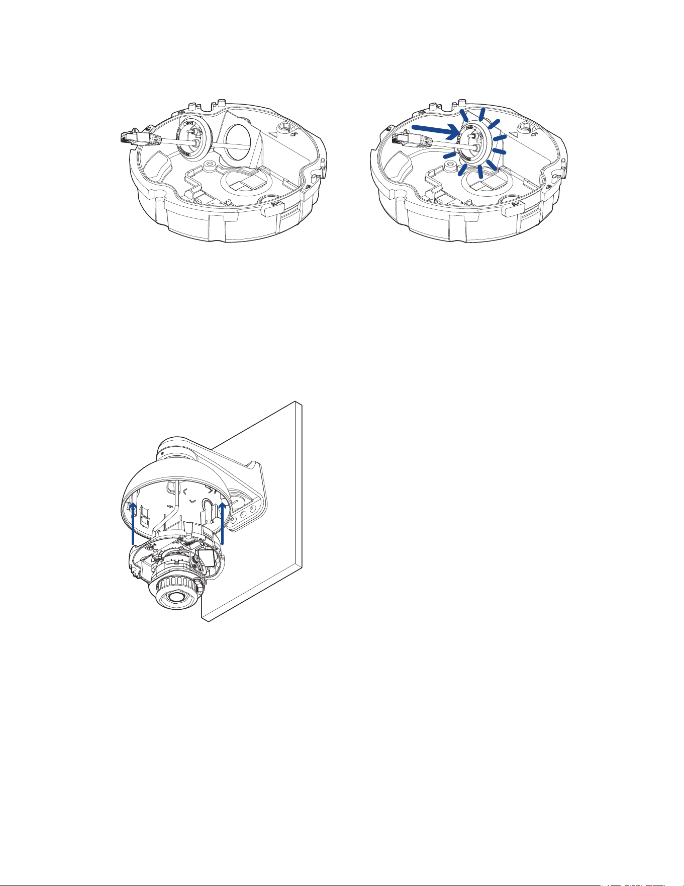
5. Installthegrommetintothecableentryholeonthecamerabase.
Makesurethegrommetissecurelyseatedontheinsideandoutsideofthecableentryhole.Apply
siliconesealanttosealanygapsinthegrommet.
6. Connectthenetworkcabletothecamera'sEthernetport.
TheLinkLEDwillturnononceanetworklinkhasbeenestablished.
7. Ifexternalpower,inputoroutputdevices,oraudiodevicesarepartoftheinstallation(forexample:
doorcontacts,relays,microphone,etc.),connectthedevicestotheI/Oconnectorblock.
Formoreinformation,seeConnecting to Power and External Devices.
8. Alignthearrowonthecamerabasetotheorangearrowonthemountingadapter,thenpressthe
camerabaseintothemountingadapter.Thecamerabaseclicksintoplaceandisheldsecurely.
Sarix Professional 4 Dome Camera Installation Manual
C6725M | 11/22
31
Connecting to the Camera
Initializing a Camera Username and Password
Youmustcreateauserwithadministratorprivilegesbeforethecameraisoperational.
Thenewusercanbecreatedusingthefollowingmethods:
l
Camera'swebinterface.Enterthecamera'sIPaddressinawebbrowsertoaccesstheweb
interface.Formoreinformation,seethePelcoSarixProfessional4DomeCameraOperations
Manual.Ifthecameraisinthefactorydefaultstate,youwillberedirectedtotheNewUserpageto
createanadministratoruser:
1. EnteranewUserNameorkeepthedefaultadministratorname.
2. EnteranewPasswordfortheuser.Itisrecommendedtouseasecureandcomplex
password.
3. Confirmthenewpassword.
4. Forthefirstuser,AdministratormustbeselectedintheSecurityGroupdrop-downmenu.
5. ClickApply.Aftercreatingtheuser,youwillbeaskedtologin.
l
CameraConfigurationTool:discoveredcamerasthatareidentifiedby willrequireafirstuserto
beset.SelecttheAdminUserstabtocreatethefirstuser.Formoreinformation,seetheCamera
Configuration Tool User Guide.
Note:Setupthefirstuserthroughthecamera'sWebInterfaceorCameraConfigurationTool
beforeyouconnectthecameratoaVMS.
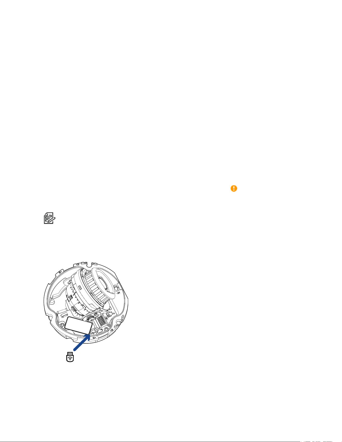
(Optional) Using the USB Wi-Fi Adapter
IfyouhaveaUSBWi-FiAdapter(USB-AC56-**-MSI),attachittothecamera'smicroUSBporttoaccess
thecamera'smobilewebinterface.
AfteryouconnecttotheWi-Fisignalbroadcastbytheadapter,youcanaccessthemobilewebinterface
fromanymobiledeviceusingthefollowingaddress:
http://camera.lan

Sarix Professional 4 Dome Camera Installation Manual
C6725M | 11/22
32
Formoreinformationaboutconfiguringthecamerafromthemobilewebinterfacesee USB Wi-Fi
Adapter System User Guide.
Thecamerawillreservethe10.11.22.32/28subnetforinternalusewhiletheUSBWi-FiAdapteris
pluggedin.
Assigning an IP Address
ThedeviceautomaticallyobtainsanIPaddresswhenitisconnectedtoanetwork.
IfthedevicecannotobtainanIPaddressfromaDHCPserver,itwilluseZeroConfigurationNetworking
(Zeroconf)tochooseanIPaddress.WhensetusingZeroconf,theIPaddressisinthe169.254.0.0/16
subnet.
TheIPaddresssettingscanbechangedusingoneofthefollowingmethods:
l
ThemobilewebinterfaceusingtheUSBWifiAdapter.Formoreinformation,see(Optional) Using
the USB Wi-Fi Adapter.
l
Device'swebbrowserinterface:http://<camera IP address>/.
l
NetworkVideoManagementsoftwareapplication.
l
ARP/Pingmethod.Formoreinformation,seeSetting the IP Address Using the ARP/Ping Method.
Setting the IP Address Using the ARP/Ping Method
CompletethefollowingstepstoconfigurethecameratouseaspecificIPaddress:
Note:TheARP/PingMethodwillnotworkiftheDisable setting static IP address through
ARP/Ping methodcheckboxisselectedinthecamera'swebbrowserinterface.Formore
information,seethePelcoSarixProfessional4DomeCameraOperationsManual.
1. LocateandmakenoteoftheMACAddress(MAC)listedontheSerialNumberTagforreference.
2. OpenaCommandPromptwindowandenterthefollowingcommands:
a. arp -s <New Camera IP Address> <Camera MAC Address>
Forexample:arp -s 192.168.1.10 00-18-85-12-45-78
b. ping -l 123 -t <New Camera IP Address>
Forexample:ping -l 123 -t 192.168.1.10
3. Rebootthecamera.
4. ClosetheCommandPromptwindowwhenyouseethefollowingmessage:
Reply from <New Camera IP Address>: ...
Accessing the Live Video Stream
Livevideostreamcanbeviewedusingoneofthefollowingmethods:
l
ThemobilewebinterfaceusingtheUSBWifiAdapter.Formoreinformation,see(Optional) Using
the USB Wi-Fi Adapter.
l
Webbrowserinterface:http://< camera IP address>/.
l
NetworkVideoManagementsoftwareapplication.
Sarix Professional 4 Dome Camera Installation Manual
C6725M | 11/22
33
Aiming the Dome Camera
Referencethecamera'slivestreamasyouaimthecamera.
1. Panthelensuntilitisaimedinthecorrectdirection.
Ifthecamerastopspanningbeforeitreachesitsfinaldestination,stopandpanthecamerainthe
oppositedirection.Ifthecameraisunabletoreachthedesiredposition,checkthatnocablesare
beingpinchedwhilethecameraturns.
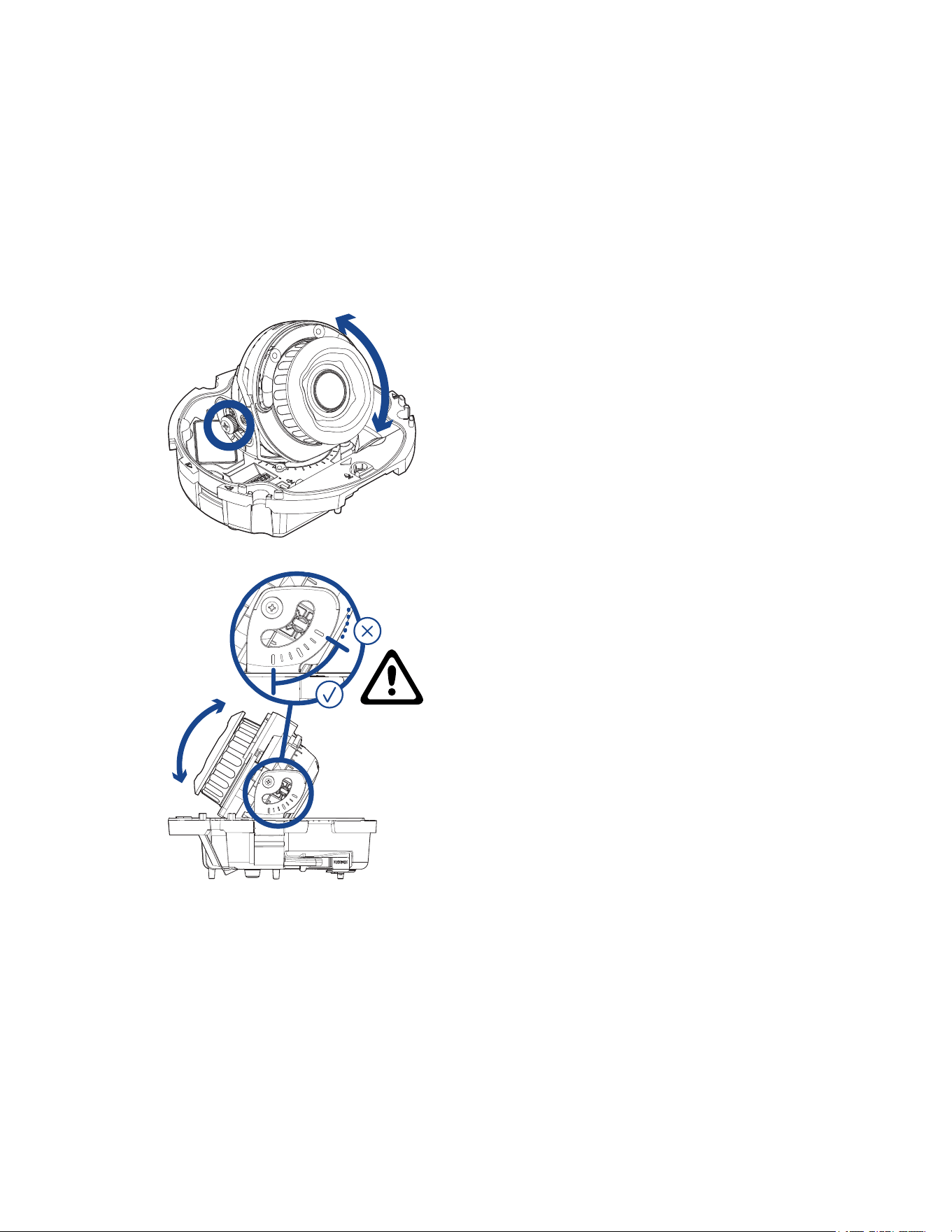
2. Loosenthetiltlockthumbscrewtotiltthelens.
3. Adjustthetiltangleofthecameraasneeded.
Pelcorecommendsthatyouadjustthetiltanglewithintherangeindicatedbythemarkingsfor
bestresults.Tiltingthecamerapastthesemarkingsispossible,butmayresultininfrared
reflectionsandviewingangleocclusionsbeyondanacceptablelevel.
4. Tightenthetiltlockscrewtosecurethedomecamera’sposition.
Sarix Professional 4 Dome Camera Installation Manual
C6725M | 11/22
34
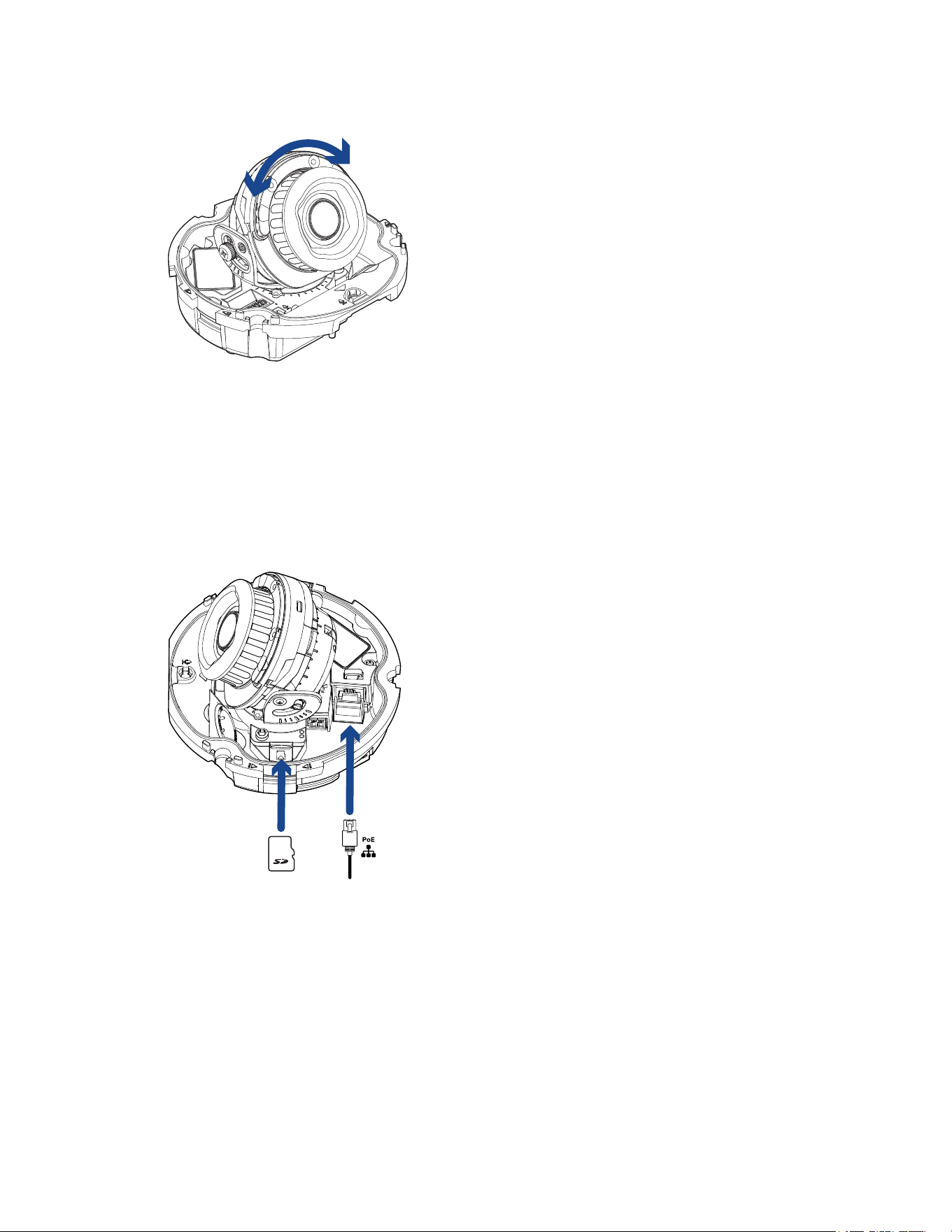
5. Rotatetheazimuthcontrolringtosettheimagetothecorrectangle.
6. Inthecamerawebbrowserinterface,adjustthecamera’sImageandDisplaysettings.
(Optional) Configuring microSD Card Storage
Tousethecamera'sSDcardstoragefeature,youmustinsertamicroSDcardintothecardslot.
ItisrecommendedthatthemicroSDcardhaveawritespeedofclass10orbetter.IfthemicroSDcard
doesnotmeettherecommendedwritespeed,therecordingperformancemaysufferandresultinthe
lossofframesorfootage.
1. InsertamicroSDcardintothecamera.DonotforcethemicroSDcardintothecameraoryoumay
damagethecardandthecamera.
2. Accessthecamera’swebinterfacetoenabletheonboardstoragefeature.Formoreinformation,
seethePelcoSarixProfessional4DomeCameraOperationsManual.
Sarix Professional 4 Dome Camera Installation Manual
C6725M | 11/22
35
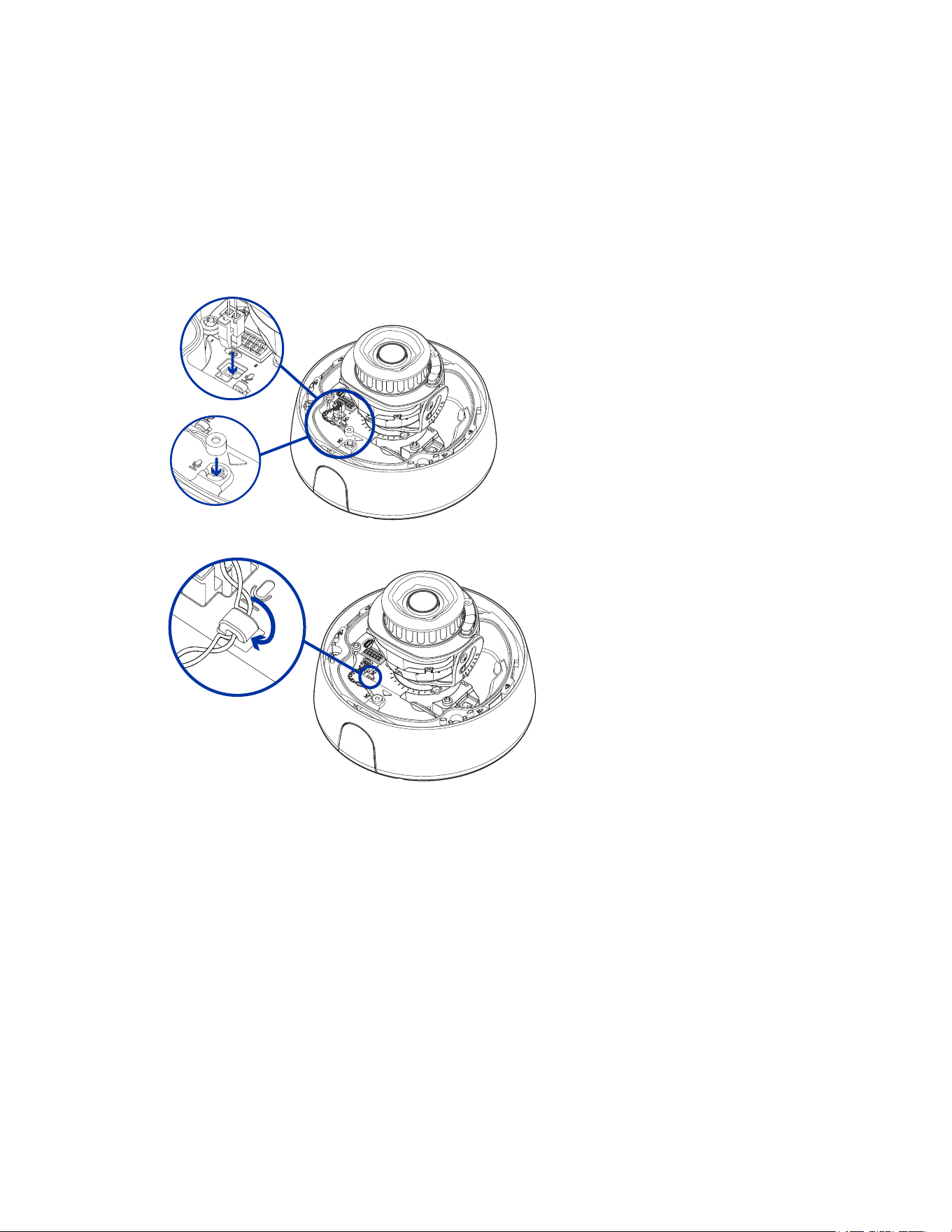
(Optional) Installing the Microphone Accessory
IfyouhaveaMicrophoneaccessory(ACMICR-1001),attachittothecamera'smicrophoneportbefore
installingattachingthedome.ThisaccessoryisonlycompatiblewithIndoormodelsandshouldNOTbe
installedwithanexternalaudiodevice.
1. SeattheMicrophoneAccessoryintothemicrophoneslotlocatedonthefrontofthecamerabase.
InserttheMicrophoneAccessory'sconnectorintothemicrophoneportbesidetheI/Oconnector
block.
1. PulltheMicrophoneAccessory'swirearoundthehookasshowntoholditinplace.
Sarix Professional 4 Dome Camera Installation Manual
C6725M | 11/22
36
Installing the Dome Cover
Beforeinstallingthedomecover,werecommendthatyoufirstconnecttothecameraandadjusttheaim,
zoom,andfocussothatthecameracoverstherequiredfieldofview.Formoreinformation,see:
l
Connecting to the Camera
l
Aiming the Dome Camera
l
Zooming and Focusing the Dome Camera
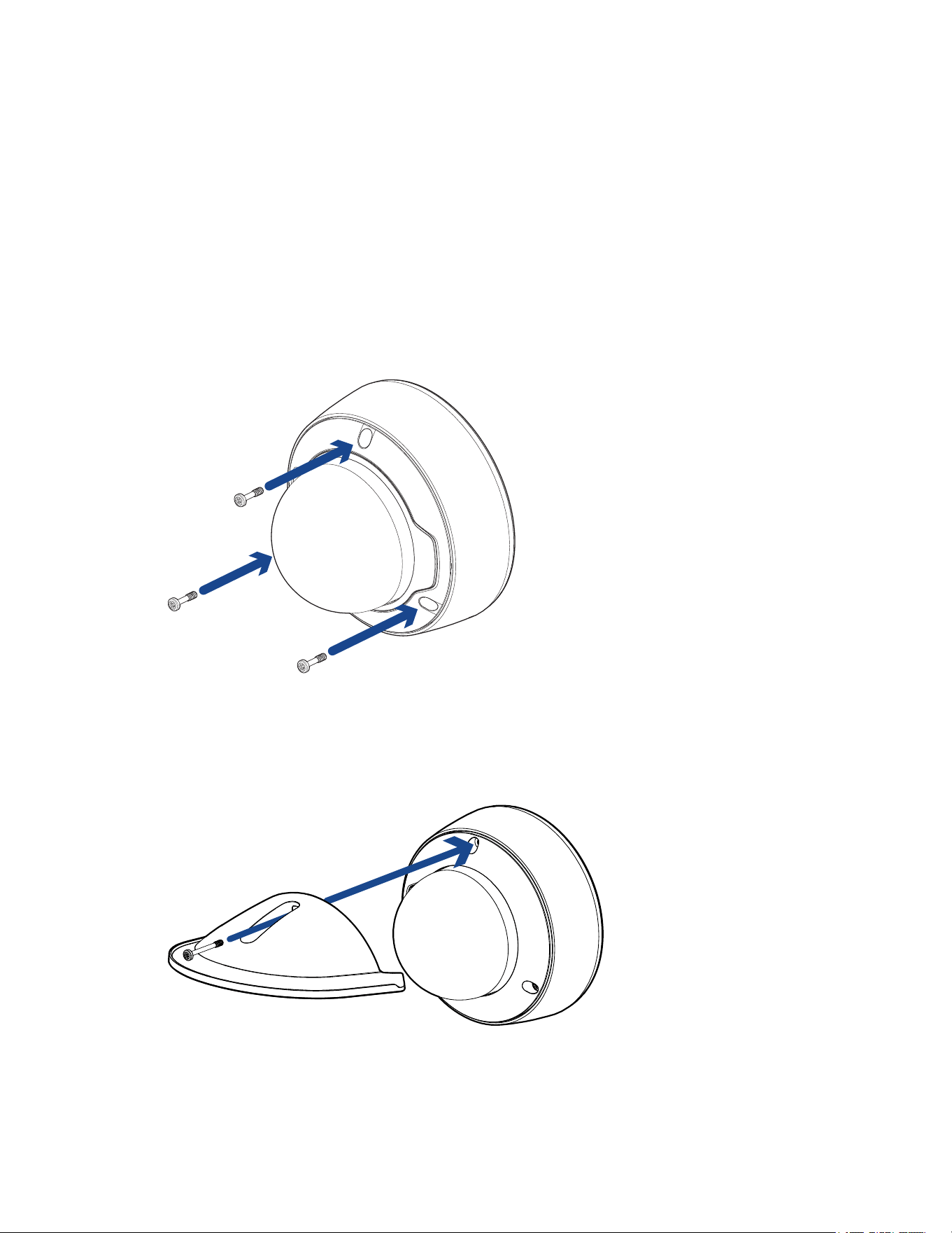
1. Alignthedomecoverscrewswiththescrewholesinthecamerabase.Applyevenpressureonthe
domecoverandtightenthescrewswiththestar-shapeddriver.
IftheoptionalWeatherShieldaccessorywillbeinstalled,onlyinstallthetwoscrewsclosesttothe
mountingadapter'ssideconduit.
2. (Optional)IfinstallingtheWeatherShieldaccessory,alignitandtheprovidedscrewwiththe
centerscrewholeonthedomecover.Ifthecaptivescrewisstillinthecenterscrewhole,unscrew
itanddiscardit.
PlacetheshieldonthedomeandtightenthescrewtosecuretheWeatherShieldontothe
camera.
3. Removetheprotectivecoverontheoutsideofthedomebubble.
Sarix Professional 4 Dome Camera Installation Manual
C6725M | 11/22
37
Zooming and Focusing the Dome Camera
Ensurethisprocedureisperformedafterthedomecoverisinstalledsoyoucanaccommodateforthe
focusshiftcausedbythedomebubble.
IfanEnvironmentalcameramodelispoweredwhilethetemperatureisbelow-30°C(-22°F),thezoom
andfocusmaybedisabledforthefirst45minuteswhilethecamerawarmsup.
l
Inthecamerawebbrowserinterface,usethecamera’sImageandDisplaysettingstozoomand
focusthecamera.
a. Usethezoombuttonstozoomthecamerainorout.
b. ClickAuto Focustofocusthelens.
c. Usethefocusnearandfarbuttonstomanuallyadjustthefocus.
Configuring the Camera
Afterthecameraisinstalled,configureitusingtheinstructionsinthecurrentversionofthePelcoSarix
Professional4DomeCameraOperationsManual.
Connecting to Power and External Devices
IfPoEisnotavailable,thecameramaybepoweredthroughtheauxiliarypowercableusingeither
12VDC.Thepowerconsumptioninformationislistedintheproductspecifications.
Topowerthecamera,connectthetwopowerwirestotheauxiliarypowerwires.Theauxiliarypowerwire
isdistinguishedbyitsthickerwiregaugeandAUX PWRlabel.Theconnectioncanbemadewitheither
polarity.
ThisproductisintendedtobesuppliedbyaULListedPowerUnitmarked“Class2”or“LPS”or
“LimitedPowerSource”withoutputrated12VDC,13Wmin.orPoweroverEthernet(PoE),
rated48VDC,13Wmin.
Toavoiddamagingthecamera,doNOTconnectauxiliarypowertotheaudioorI/Oterminal
block,anddoNOTinstalltheMicrophoneaccessoryandanexternalaudioinputdevice
simultaneously.
PowersuppliesandexternaldevicesareconnectedtothecamerathroughthepowerandI/Owires.
ForthelocationsofthepowerandI/Oconnectorblocks,seeOverview.
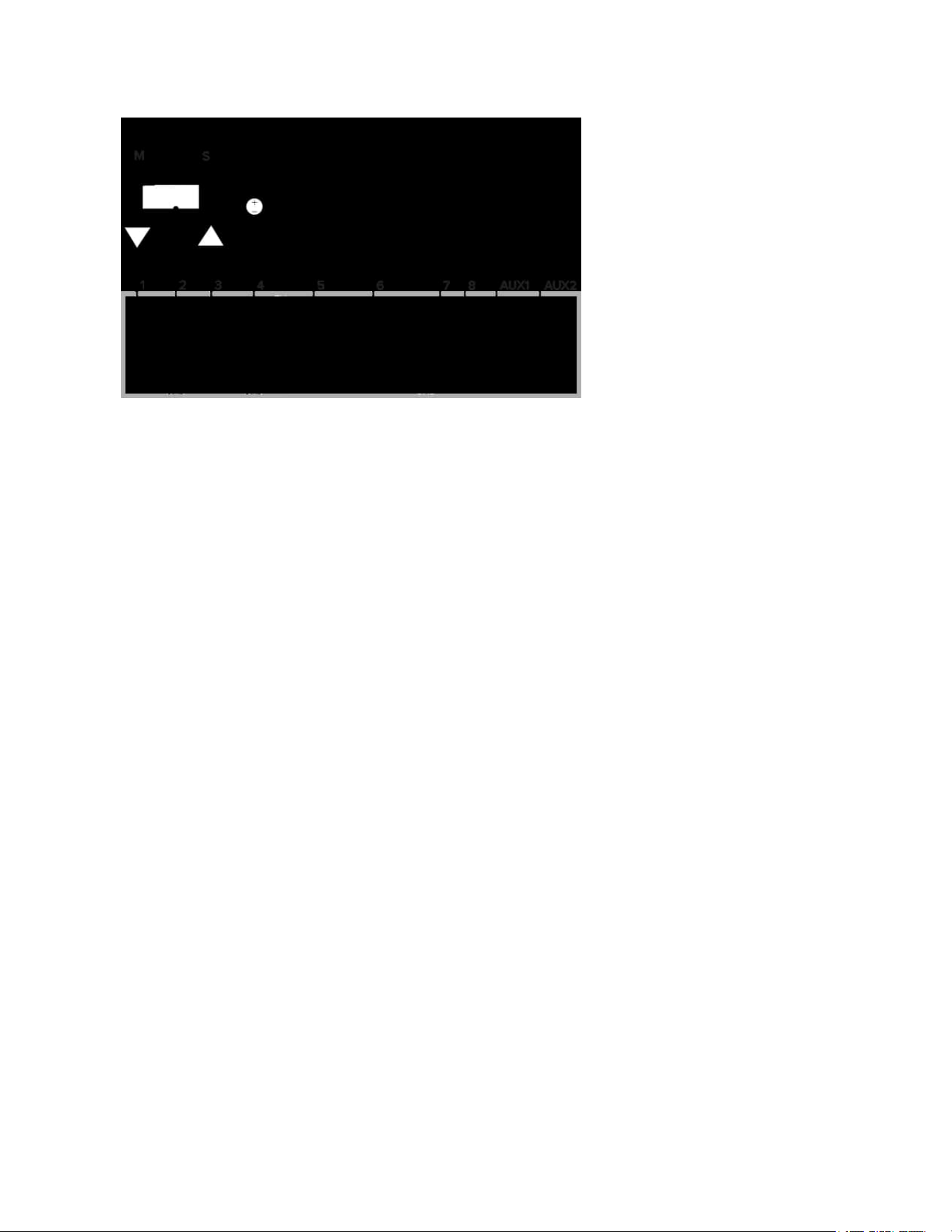
ThepinoutfortheI/Oandpowerwiresisshowninthediagramonthefollowingpage.
Sarix Professional 4 Dome Camera Installation Manual
C6725M | 11/22
38
Exampleapplication.
1. AudioInput(linelevel)
Anexternalpoweramplifiershouldbeusedwhenconnectingspeakersandmicrophones,as
showninthediagram.
2. AudioGround
3. AudioOutput(linelevel)
4. Ground
5. DigitalInput
6. DigitalOutput
7. ReservedWire,donotconnect.
8. ReservedWire,donotconnect.
l
*—Relay
l
**—Switch
l
M—Microphone
l
S—Speaker
l
AUX1—AuxiliaryPowerWire,labeledAUX PWR
l
AUX2—AuxiliaryPowerWire
Sarix Professional 4 Dome Camera Installation Manual
C6725M | 11/22
39
Connection Status LED Indicator
Onceconnectedtothenetwork,thegreenConnectionStatusLEDindicatorwilldisplaytheprogressin
connectingtotheNetworkVideoManagementsoftware.
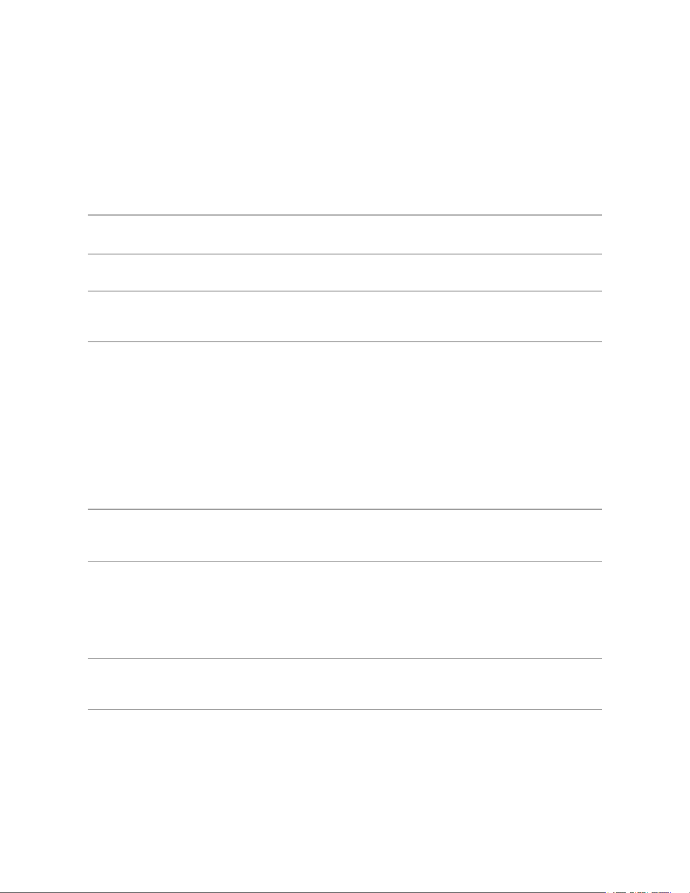
ThefollowingtabledescribeswhattheLEDindicatorshows:
Connection State Connection
Status LED
Indicator
Description
Obtaining
IPAddress
Oneshortflash
everysecond
AttemptingtoobtainanIPaddress.
Discoverable Twoshortflashes
everysecond
ObtainedanIPaddressbutnotconnectedtothe
NetworkVideoManagementsoftware.
Upgrading
Firmware
Twoshortflashes
andonelongflash
everysecond
Updatingthefirmware.
Connected On ConnectedtotheNetworkVideoManagementsoftware.
ThedefaultconnectedsettingcanbechangedtoOffusing
thecamera'swebuserinterface.Formoreinformation,see
thePelcoSarixProfessional4DomeCameraOperations
Manual.
Troubleshooting Network Connections and LED Behavior
ForanyofthebelowLEDbehaviors,ensurethatthecameraisgettingpowerandisusingagood
networkcablebeforetryinganothersolution.
LED Behavior Suggested Solution
GreenLEDisoffandamberison Performafactoryresetofthecamerausingthephysical
firmwarerevertbutton.Resettingthroughthecamera'sweb
interfacewillnotproducethedesiredresult.
BothLEDsareoffandthecameraisnot
connectedorstreamingvideo
ChecktheGeneralsetuppageinthecamera'swebinterface
toensuretheLEDsarenotdisabled.
IftheLEDsarenotdisabled,performafactoryresetofthe
camerausingthephysicalfirmwarerevertbutton.Resetting
throughthecamera'swebinterfacewillnotproducethe
desiredresult.
BothLEDsareblinkingseveraltimesat
thesametime,thenpauseandrepeat
theblinking
Performafactoryresetofthecamerausingthephysical
firmwarerevertbutton.Resettingthroughthecamera'sweb
interfacewillnotproducethedesiredresult.
AdifferentLEDblinkingpatternthan
thosedescribedabove
Performafactoryresetofthecamerausingthephysical
firmwarerevertbutton.Resettingthroughthecamera'sweb
interfacewillnotproducethedesiredresult.
Sarix Professional 4 Dome Camera Installation Manual
C6725M | 11/22
40
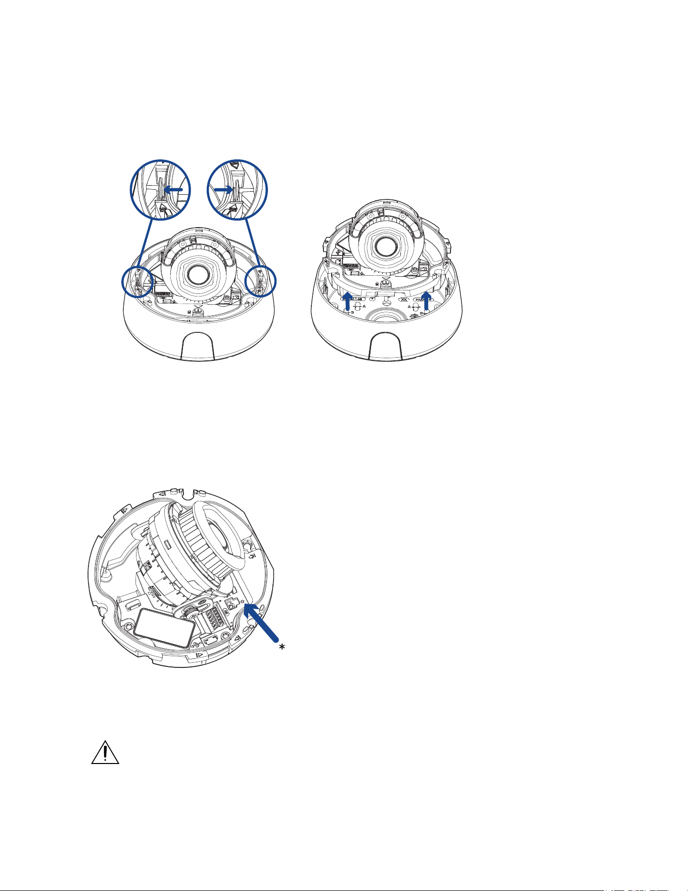
Removing the Dome Camera from the Mounting Adapter
1. Loosenthestar-shapedscrewsandremovethedomecover.
2. Locatethesmallarrowsthatpointatthecamerahousingclips.
3. Pushthecamerahousingclipsoutwardsuntilthecamerasnapsoutofplace.
4. Liftthecamerabaseoutoftheadapter.
Resetting to Factory Default Settings
Ifthedevicenolongerfunctionsasexpected,youcanchoosetoresetthedevicetoitsfactorydefault
settings.
Usethefirmwarerevertbuttontoresetthedevice.Thefirmwarerevertbuttonisshowninthefollowing
diagram:
1. Ensurethedeviceispoweredon.
2. Usingastraightenedpapercliporsimilartool,gentlypressandholdthefirmwarerevertbutton.
3. Releasethebuttonafterthreeseconds.
Donotapplyexcessiveforce.Insertingthetooltoofarmaydamagethecamera.

Sarix Professional 4 Dome Camera Installation Manual
C6725M | 11/22
41
For More Information
Additionalinformationaboutsettingupandusingthedeviceisavailableinthefollowingguides:
l
PelcoSarixProfessional4DomeCameraOperationsManualavailableonthePelcowebsite:
www.pelco.com.
l
Camera Configuration Tool User Guide
Pelco Troubleshooting Contact Information
Forfurtherassistance,contactPelcoProductSupportat1-800-289-9100(USAandCanada)or+1-559-
292-1981(international).
Donottrytorepairtheunityourself.Leavemaintenanceandrepairstoqualifiedtechnicalpersonnel
only.

Sarix Professional 4 Dome Camera Installation Manual
M
Pelco, Inc.
625 W. Alluvial Ave., Fresno, California 93711 United States
(800) 289-9100 Tel
(800) 289-9150 Fax
+1 (559) 292-1981 International Tel
+1 (559) 348-1120 International Fax
www.pelco.com
Pelco, the Pelco logo, and other trademarks associated with Pelco products referred to in this publication are trademarks of Pelco,
Inc. or its affiliates. ONVIF and the ONVIF logo are trademarks of ONVIF Inc. All other product names and services are the property of
their respective companies. Product specifications and availability are subject to change without notice.
© Copyright 2022, Pelco, Inc. All rights reserved.


