Loading ...
Loading ...
Loading ...

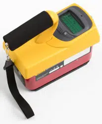
Ion Chamber Survey Meter
Maintenance
11
4. Remove screws holding phenolic chamber cover to the base.
5. Determine the conductive side of the replacement Mylar sheet using an ohmmeter.
6. Carefully, so as not to crinkle it, place the new Mylar on the top of the chamber,
conductive side facing the chamber. Use adhesive to secure the Mylar to the phenolic
chamber.
7. Electrically connect conductive side of Mylar to conductive side of chamber.
8. Any wrinkles in the Mylar may be removed with a hot air gun. Do not apply too
much heat; the Mylar may break. Small ripples in the surface will not affect the
operation of the instrument. Attach phenolic chamber to the base.
9. Secure the case top to the case bottom, with the gasket in between, using the four
screws removed in step 2.
10. Replace the 9-volt batteries, being sure to observe proper polarity.
Outer Mylar Window Replacement
1. Remove the 9-volt batteries to be sure that the instrument will remain off during the
disassembly process.
2. Remove the 4 screws from the case top.
3. Carefully remove the case bottom from the thick gasket that seals the top and bottom.
4. Remove the damaged Mylar. Replace with the conductive side facing up, secure with
proper adhesive.
5. Dag conductive side of Mylar to inside of case.
6. Secure the case top to the case bottom, with the gasket in between, using the 4 screws
removed in step 2.
7. Replace the 9-volt batteries, being sure to observe proper polarity.
Desiccant Regeneration
W Warning
This unit contains lithium cells with a potential voltage of 63 V
on the battery assembly. Use care in handling this assembly
during removal and installation. Damage to the instrument or
bodily harm may result.
Note
The repair area should be clean and free from dust and debris.
1. Remove the 9-volt batteries to be sure that the instrument will remain off during the
disassembly process.
2. Remove the 4 screws from the case top/bottom (see Figure 3).
3. Carefully remove the case bottom from the thick gasket that seals the top and bottom.
4. Remove desiccant vial from battery assembly in Unit (see Figure 4) by slipping vial
from clamp (do not pull out).
5. Remove cap from vial (leave desiccant in vial), and bake silica gel at 50 °C for
24 hours.
6. Reinstall the cap and install the desiccant vial into the unit by slipping it into the
clamp.
7. Secure the case top to the case bottom, with the gasket in between, using the four
1.888.610.7664 sales@GlobalTestSupply.com
Fluke-Direct.com
Loading ...
Loading ...
Loading ...