Loading ...
Loading ...
Loading ...
481
Operators Manual
8
W Caution
The user is cautioned about indiscriminately opening and
disassembling the instrument. The high impedance circuits of
the ion chamber are easily contaminated with grease and dirt
that produce electrical leakage. Complete
Assembly/Disassembly instructions are available in the
Maintenance Section of this manual.
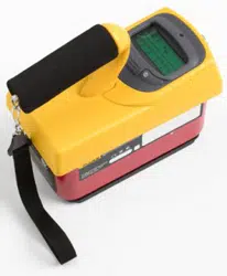
The Model 481 is an air ionization chamber instrument calibrated in exposure rate units
of roentgens/hour (or Sieverts/hour) for gamma and x-ray in the energy range of 20 keV
to 2 MeV through the sliding Phenolic shield. It can also be used for x-ray in the energy
range of 7 keV to 30 keV with the sliding shield open. The Model 481 responds to, but is
not calibrated for, beta radiation, with the slide open. Beta energies that can be measured
are above 100 keV. The two thin Mylar windows have a combined density thickness of
6.6 mg/cm2.
The liquid crystal display shows the radiation rate in digital and analog form with the
range multiplier values also showing on the scale. It is a lightweight electronic device
that requires the computational capabilities of a microprocessor to make it operate. It
functions in a multiplex mode called quadruplex. This mode uses four backplanes to
accommodate the 128 elements of the display.
The microprocessor performs data collection, averaging, and multiplication by stored
calibration factors, range changing, and battery check functions, in addition to driving the
LCD. Between computational periods, it “sleeps” in a low power mode to conserve
battery power. The microprocessor reads stored information from an electrically erasable
memory, EEPROM, which is used by the program for calibration and display units. The
EEPROM will retain stored data when the instrument is OFF or when the batteries are
removed. Data can be entered into the EEPROM using the RS-232 port.
63 V collection voltage for the ion chamber is obtained from lithium cells that have a
10-year life. All internal power for the instrument is supplied by the 9 V batteries,
accessible from the rear of the instrument.
The digital and bar graph displays read directly. The bar graph display update periods are
listed in Table 1. The digital display updates at one second intervals nearest the current
bar display update. The bar graph and digits display do not always show the same reading
because the bar graph is faster than the digital update. It is more convenient to watch the
bar graph when the reading is changing quickly and to read the value of a slowly
changing or static reading by looking at the digital display.
The bar graph display is a digital presentation, programmed to appear as a linear analog
meter display. It is also referred to as the analog display throughout this manual.
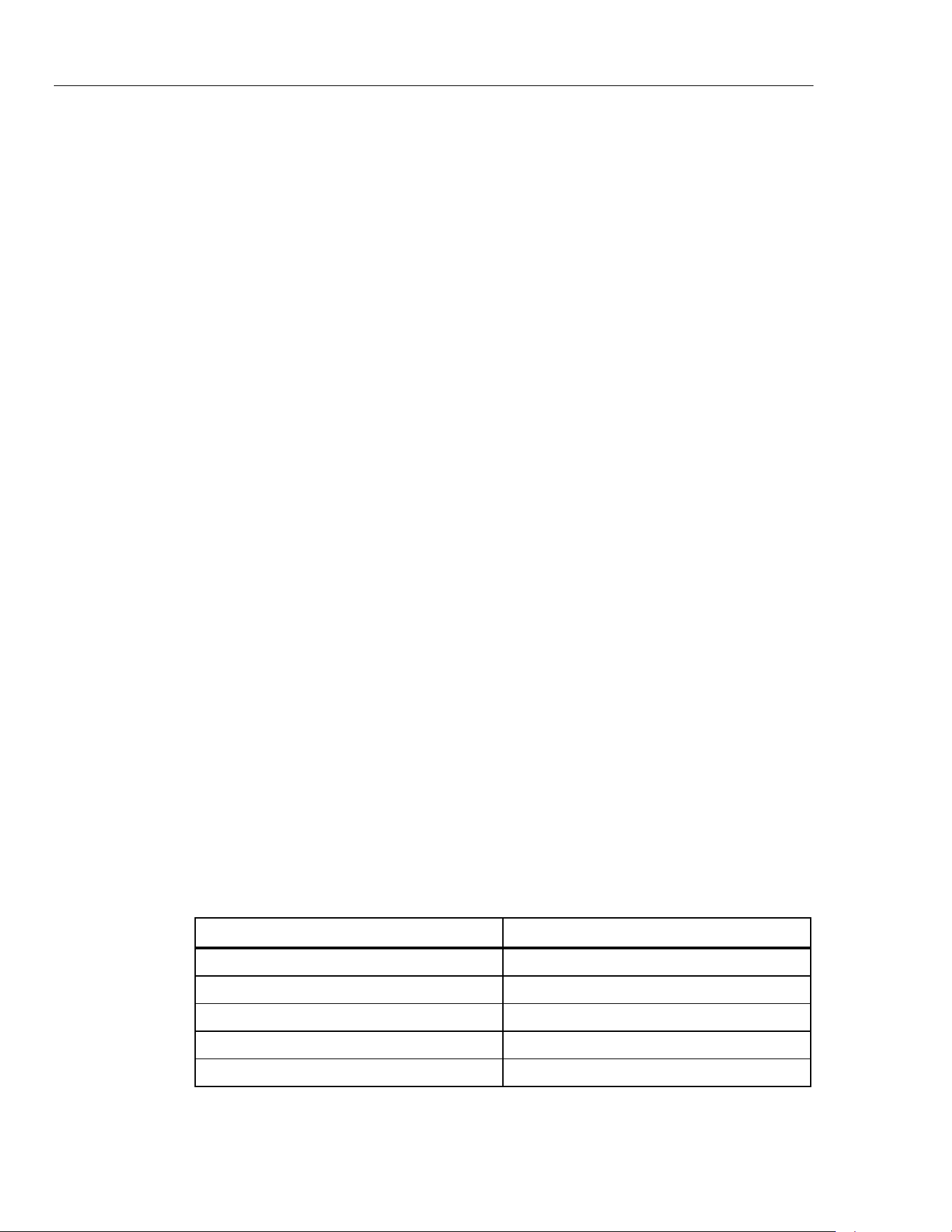
Table 1. Bar Graph Display Update Periods
Range Update Period
50 R/h (500 mSv/h) 0.05 second
5 R/h (50 mSv/h) 0.1 second
500 mR/h (5 mSv/h) 0.1 second
50 mR/h (500 μSv/h) 0.15 second
5 mR/h (50 μSv/h) 0.25 second
There are 20 bars between each major division. The numerical values of the five major
divisions change appropriately for the range in which the instrument is operating. For
instance, the first major division would have the numeric value of 1, 10, or 100. The
1.888.610.7664 sales@GlobalTestSupply.com
Fluke-Direct.com
Loading ...
Loading ...
Loading ...