CTUAU04
Infodapter Interface
for Audi Vehicles
APPLICATION
FEATURES
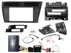
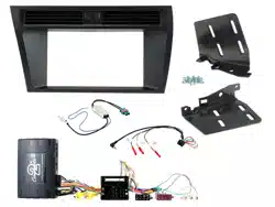
Audi A4 (8K) 2008 - 2016
Audi A5 Coupe (8TF, 8F7, 8TA) 2008 - 2016
• Retains Steering Wheel Control Functionality
• Retains Phone Button Functionality
• Retains Amplied System
• Retains Vehicle Settings and Generates Settings Menus
• Provides Input for Aftermarket Reversing Camera
• Retains Parking Sensor Audio and Generates Parking Sensor Graphics
• Provides Outputs for Park Brake, Reverse Gear, Speed Pulse and Mute
• Updateable via USB (contact supplier for more information)
The information provided in this document is subject to change without notice due to manufacturer changes and/or improvements to the product/s. This
instruction manual is based on documented data and research. The manufacturer of this product cannot be held responsible for any changes made to the
vehicle by the manufacturer or damages that may occur through the installation of this product in accordance with the steps outlined herein.
Note: Application data is subject to change at any time
DISCLAIMER
For amplied vehicles with basic Non-MMI systems only
CTUAU04_IG_en-GB_v2
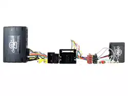
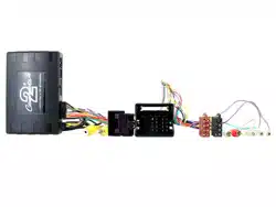
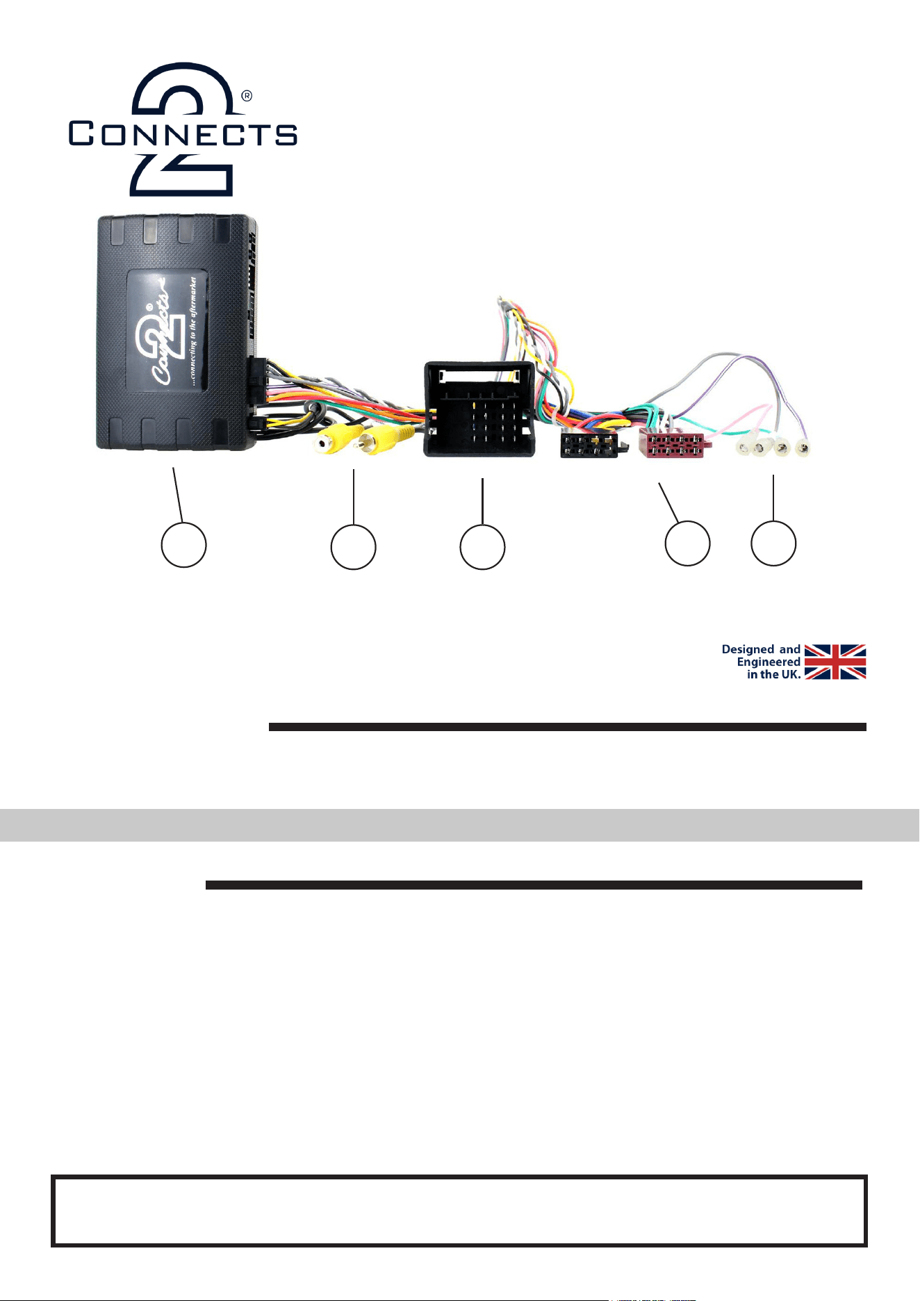
i. Interface Box
ii. Video/Camera RCA (Yellow)
iii. Quadlock Connector
iv. ISO Connector
v. Flying Wires
i
ii iii
vi v

2
CTUAU04_IG_en-GB_v2
PRIOR TO INSTALLATION
Read the manual prior to installation. Technical knowledge is necessary for installation. The place of instal-
lation must be free of moisture and away from heat sources. Please ensure that the correct tools are used
during the installation to avoid damage to the vehicle or product. Connects2 can not be held responsible for
the installation of this product.
IN ISO CONNECTOR
Purple Right Rear Speaker +
Purple/Black Right Rear Speaker -
Green Left Rear Speaker +
Green/Black Left Rear Speaker -
Grey Right Front Speaker +
Grey/Black Right Front Speaker -
White Left Front Speaker +
White/Black Left Front Speaker -
ADDITIONAL CONNECTIONS
Pink Speed Pulse
Green Park Brake
Purple/White Reverse Gear
Grey Mute
WIRING KEY
Yellow Permanent 12V
Black Ground
Red Ignition 12V
Orange Illumination
Yellow RCA (Male) Infodapter Display Video
Yellow RCA (Female) Connect Aftermarket Camera
!
Please be aware that whilst we retain most of the original vehicle features with our interfaces,
some features may be lost. As we continue our research, this product can be updated to support
even more OEM functionality.
Currently, this interface can support the following features: Language, Temperature, Time Format,
Date Format, Tyre Pressure, Distance Units, Speed Units, Suggested Gear Change, Speed Warning,
Board Computer 1/2, Auto Headlights, Leaving Home, Come Home Light Time, Daytime Running
Lights, Head Lamp Conversion, Unlock Single Door, Auto Locking, Boot Lid and Tailgate, Parking
Volume Front/Rear, Parking Freq Front/Rear, Oil Check, Service Due, Window Convenience Open
Front/Rear, Windscreen Wiper Service Position, Rain Sensor.
3
Need help? Visit support.connects2.com/tickets/technical
CTUAU04_IG_en-GB_v2
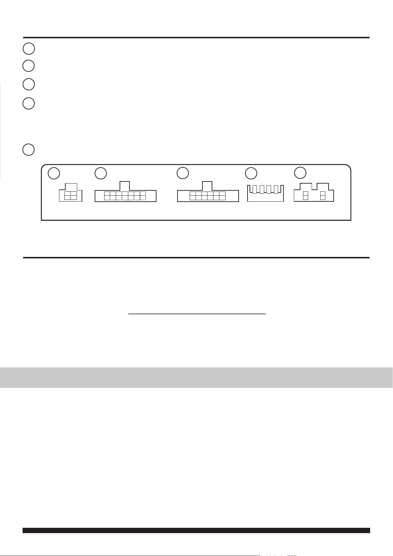
INTERFACE CONNECTIONS
1 2 3 4
DIP Switch 1 - ‘ON’ for Pioneer, ‘OFF’ for other brand head unitsDIP Switch 1 - ‘ON’ for Pioneer, ‘OFF’ for other brand head units
DIP Switch 2 - ‘ON’ for PAL reversing camera, ‘OFF’ for NTSC reversing camera (Default is ‘OFF’/NTSC)DIP Switch 2 - ‘ON’ for PAL reversing camera, ‘OFF’ for NTSC reversing camera (Default is ‘OFF’/NTSC)
DIP Switch 3 - Change from ‘OFF’ to ‘ON’ and back to reset screen settings to factory defaults. DIP Switch 3 - Change from ‘OFF’ to ‘ON’ and back to reset screen settings to factory defaults.
Note: During this procedure, the screen background will change to red and no settings adjustments can be made.Note: During this procedure, the screen background will change to red and no settings adjustments can be made.
DIP Switch 4 - Not UsedDIP Switch 4 - Not Used
1
2 3
4
5
1
4
2
3
5
Reverse Camera Extension Harness InputReverse Camera Extension Harness Input
Power Harness InputPower Harness Input
Head Unit Connection (Patch) Lead InputHead Unit Connection (Patch) Lead Input
Not usedNot used
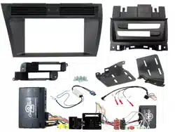
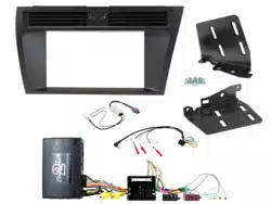
INSTALLATION GUIDE
See Wiring Diagram on Pg.4 for more information
Before installing the interface, the factory stereo must be removed and disconnected. To do this, please consult the vehicle
owner’s manual/handbook or contact a tting professional.
A stereo connection (patch) lead is also required for the installation of this interface (supplied seperately). Please ensure
that you have the correct lead before proceeding. For universal patch leads, prepare the wiring loops in accordance with the
instruction manual supplied with the product before installation.
1. Connect the 12 Pin connector from the stereo connection (patch) lead to the interface box
2. Connect the opposite end of the stereo connection (patch) lead to the steering wheel control input on the back of the
aftermarket stereo
NOTE: This may be a 3.5mm jack connector or a wired input depending on the brand of aftermarket stereo being tted.
Please consult the aftermarket stereo installation manual for further information on where to make the connection
IMPORTANT: THIS STEP MUST BE COMPLETED BEFORE CONNECTING POWER TO THE INTERFACE.
FAILURE TO DO SO MAY RESULT IN A LACK OF FUNCTIONALITY AND THE NEED TO REINSTALL THE PRODUCT
!
3. Connect the 14 Pin connector from the supplied wiring loom to the interface box
4. Connect 4 Pin camera extension harness to the interface box
5. Connect the power/speaker ISO connector to the power/speaker ISO connector at the rear of the aftermarket stereo.
6. Connect ying wires from the main wiring harness to the head unit. See ‘Additional Connections’ for more informa-
tion.
7. Connect the male yellow RCA from the camera extension harness to the reverse camera input of the aftermarket
head unit
8. To add an aftermarket reversing camera: connect female yellow RCA from the camera extension harness to the
male yellow RCA of the aftermarket camera
9. Connect the quadlock connector on the supplied harness to the quadlock connector from the vehicle
10. Test stereo and steering wheel control functionality for correct operation before reassembling the
vehicle dashboard. If steering wheel control functions are unresponsive, please uninstall the interface and wiring and
reinstall carefully in accordance with the above steps.
4
CTUAU04_IG_en-GB_v2
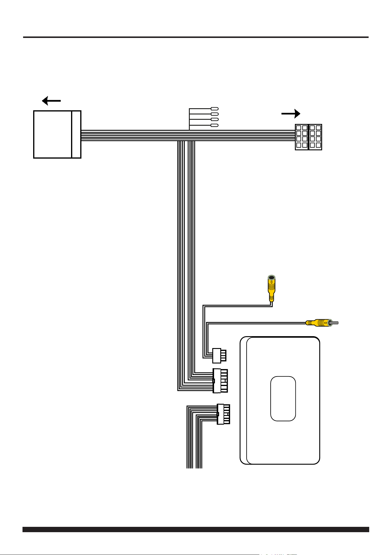
WIRING DIAGRAM
ISO Connector
Connect to aftermarket stereo
Quadlock Connector
Connect to quadlock connector from vehicle
Stereo Connection (Patch) Lead Connector [12 Pin]
Connect to Interface Box
Note: Must be connected first, before power
connection is made to the interface
Main Wiring Loom Connector [14 Pin]
Connect to Interface Box
Flying Wires
Pink - Speed Pulse
Green - Park Brake
Purple/White - Reverse Gear
Grey - Mute
Male Yellow RCA Connector
Connect to aftermarket radio
camera input
Female Yellow RCA Connector
Connect aftermarket camera
ADD-ON AFTERMARKET CAMERA
5
Need help? Visit support.connects2.com/tickets/technical
CTUAU04_IG_en-GB_v2
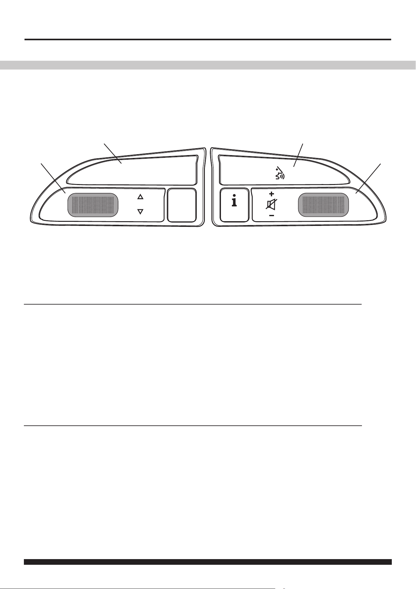
NAV
MODE
OK
USER GUIDE
The following diagram, though based on careful research, is an example only. Individual steering wheel control congurations may differ.
1
2 4
1. Track + (Scroll Up)
Track - (Scroll Down)
Source (Short Press)
Enter Infodapter Menu (Long Press)
2. Source (Short Press)
Enter Infodapter Menu (Long Press)
3
In Normal Mode
In Infodapter Menu
1. Menu Up (Scroll Up)
Menu Down (Scroll Down)
Select Menu Item (Short Press)
2. Select Menu Item (Short Press)
To exit the Infodapter Menu, select ‘EXIT’
STEERING WHEEL CONTROL FUNCTIONALITY
3. Volume + (Scroll Up)
Volume - (Scroll Down)
4. Pick Up (Short Press)
Hang Up (Long Press)
3. Volume + (Scroll Up)
Volume - (Scroll Down)
4. Pick Up (Short Press)
Hang Up (Long Press)
6
CTUAU04_IG_en-GB_v2
INFODAPTER MENU
Press and hold Button 1 or Button 2 to enter the Infodapter
Conguration menu and navigate through the various options
and settings below:
Conguration Menu
Drive Select Settings
Vehicle Settings
Infodapter Settings
Language
Version
Back
DRIVE SELECT SETTINGS
-> Individual / Comfort / Auto / Dynamic / Off Road /
Eciency
Select the desired drive mode from the list of options
Conguration Menu
Drive Select Settings
Vehicle Settings
Infodapter Settings
Language
Version
Conguration Menu
Drive Select Settings
Vehicle Settings
Infodapter Settings
Language
Version
VEHICLE SETTINGS
The Infodapter interface currently retains the following vehicle
settings*:
*Note: Although care has been taken to ensure the accuracy of this menu struc-
ture at the time of printing this document, sudden changes in software by the
manufacturer or incompatibilities with the interface cannot be accounted for.
Do not consider this list to be exhaustive.
Unit Settings
-> Distance
-> Speed
-> Temperature
-> Tyre Pressure Units
Time/Date
-> Hours
-> Minutes
-> Years
-> Month
-> Day
-> Set Time Format
-> Set Date Format
Speed
-> Speed Warning
-> Speed Warning At
-> Suggested Gear Change
Lights
-> Come Home Light Time
-> Leaving Home Lights
-> Auto Headlights
-> Daytime Running Lights
-> Headlamp Converter
Central Locking
-> Unlock Single Door
-> Auto Locking
-> Boot Lid & Tailgate
Parking System
-> Display
-> Front Volume
-> Front Frequency
-> Rear Volume
-> Rear Frequency
Windows & Wipers
-> Convenience Open Front
-> Convenience Open Rear
-> Wiper Service Position
-> Rain Sensors
Instrument Cluster
-> Engine Oil Level
-> Oil Service
-> Service
-> Board Computer 1
-> Fuel Range
-> Average Consumption
-> Current Consumption
-> Average Speed
-> Driving Time
-> Distance Travelled
-> Board Computer 2
-> Fuel Range
-> Average Consumption
-> Current Consumption
-> Average Speed
-> Driving Time
-> Distance Travelled
7
Need help? Visit support.connects2.com/tickets/technical
CTUAU04_IG_en-GB_v2
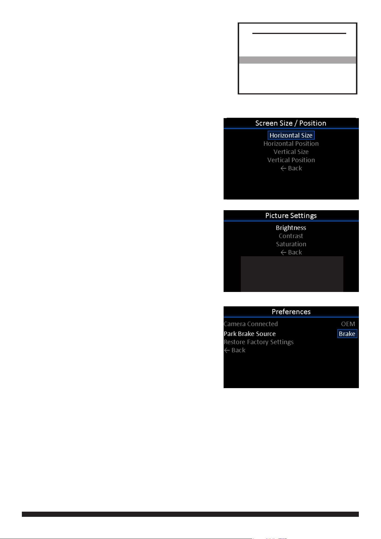
INFODAPTER SETTINGS
-> Screen Size/Position
-> Horizontal Size
-> Horizontal Position
-> Vertical Size
-> Vertical Position
-> Picture Settings
-> Brightness
-> Contrast
-> Saturation
-> Preferences
-> Camera Connected
Choose the style of camera connected to the vehicle
(if applicable)
-> Park Brake Source
Set Park Brake output to activate when park brake
is on (Brake), when speed is less than 3km/h
(Speed) or to remain on at all times (Always On)
-> Restore Factory Settings
Select Yes to return all Infodapter settings to factory
defaults
Conguration Menu
Drive Select Settings
Vehicle Settings
Infodapter Settings
Language
Version
Back
LANGUAGE
-> Select language (English/French/German/etc)
VERSION
-> View software version screen
8
CTUAU04_IG_en-GB_v2
Need Help?
Send us a ticket online 24/7
Troubleshoot with our skilled team
Get support until your issue is resolved
No problem.
support.connects2.com/tickets