
Loading ...
Loading ...
Loading ...
52
3.5 Connecting the Camera
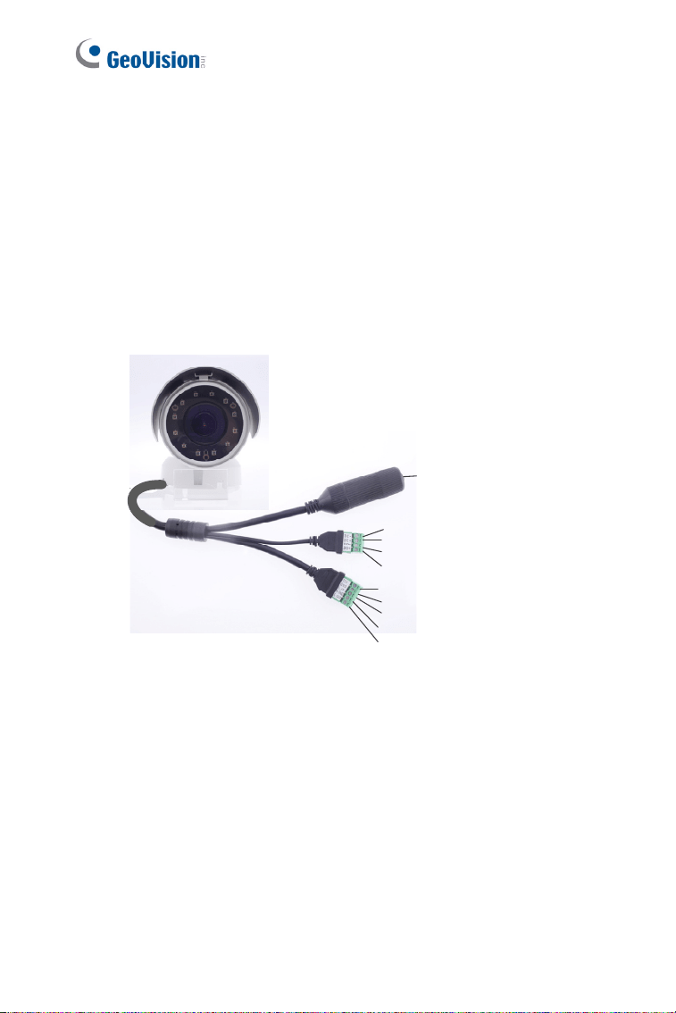
3.5.1 Wire Definition
The 4-Pin terminal block supports 1 digital input and 1 digital output of dry
contact.. For details on how to enable an installed I/O device, see 4.2 I/O
Settings, GV-IPCam Firmware Manual. The 5-Pin terminal block provides
power input, 1 audio input and 1 audio output. The wires are illustrated and
defined below:
Ethernet (PoE)
4-Pin terminal block
5-Pin terminal block
1
2
3
4
5
6
7
8
9
Figure 3-16
Loading ...
Loading ...
Loading ...