
Loading ...
Loading ...
Loading ...
CAUTION: USE CARE HANDLING BATTERY. CARELESS OR
IMPROPER HANDLING MAY RESULT IN SERIOUS INJURY.
15
GENERAL RECOMMENDATIONS
• A standard “U1” Battery is recommended. If the
B
attery is put into service after the “month and
year” of the date on the Battery, it may need to be
charged with a 12 volt Battery charger for a
minimum of 1 hour, but no more than 2 hours at a
rate of 6 to 10 amps.
• Use pliers on Thumbscrews if they are too tight to
turn by hand. Do not re-tighten with pliers.
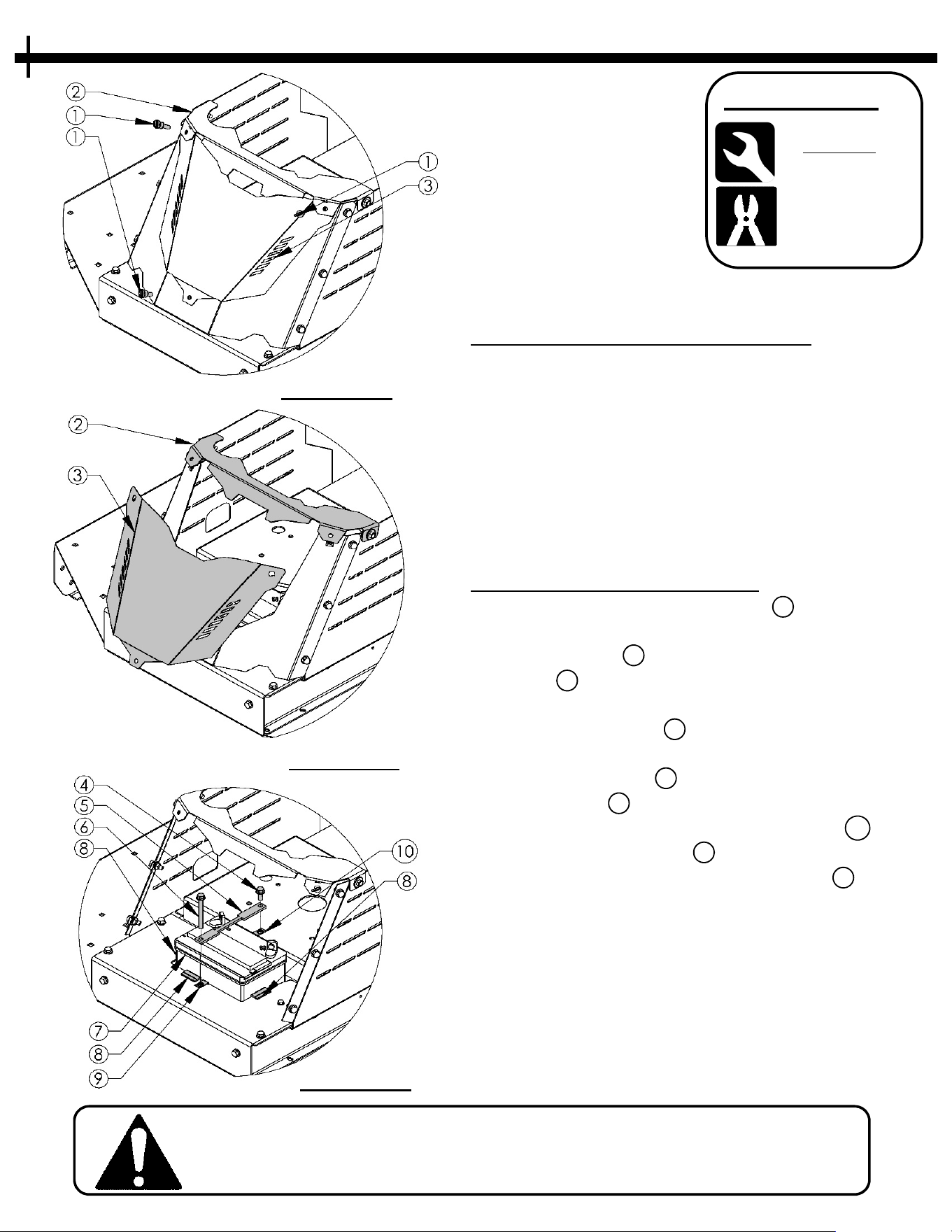
INSTALLATION / REMOVAL
• Remove the three Thumbscrews 1 holding the
B
attery Cover as shown in Figure 15.1.
• Tilt top Cover 2 slightly upward and slide Battery
Cover 3 down & out to remove. Figure 15.2
• Place U1 Battery into opening. Ensure the three
rubber edge guards 8 are in place before inserting
Battery. Figure 15.3
• Lay Battery strap 5 over Battery. Insert one 5/16-
18 x 1” Bolt 4 thru Battery strap hole near engine
and hand thread into the Tinnerman Clip 10 .
Insert 5/8-16 x 3” Bolt 6 thru hole in opposite end
of strap and thread into Tinnerman Clip 9 shown
in Figure 15.3. Tighten both bolts with ½” wrench
being careful not to over tighten and deform the
Battery strap.
• For removal of Battery, follow steps in reverse
order.
• See Page 16 for Battery wiring directions
Wrench/Socket
Q
ty. Size
(2) 1/2”
T
ools Required:
FIGURE 15.1
FIGURE 15.2
FIGURE 15.3
See P
age 24 for replacement part numbers
BATTERY
Pliers
(
Optional)
Loading ...
Loading ...
Loading ...