

FLEXIDOME 8100i | FLEXIDOME 8100i — X series Table of contents | en 3
Bosch Security Systems, BV
Installation manual
2024-11 | V01 | F.01U.411.088
Table of contents
1
Safety and security information 4
1.1 Safety message explanation 4
1.2 Safety precautions 4
1.3 Important safety instructions 4
1.4 Notices 5
2
Short information 7
3
System overview 8
3.1 Product description 8
3.2 Intended use 8
4
Preparing for installation 9
4.1 Unpacking 9
4.2 Parts included 9
4.3 Preparation 10
4.4 Wiring 11
4.4.1 Network and PoE power 11
4.4.2 24V AC/12-26V DC power input 12
4.4.3 10-pin I/O connector 12
4.4.4 Grounding 13
5
In-box configuration 14
6
Hardware installation 15
6.1 Installing the mounting plate 15
6.1.1 Installing the mounting plate without conduit 16
6.1.2 Installing the mounting plate with conduit 18
6.2 Installing the camera base 23
6.2.1 Before the installation 23
6.2.2 Installation steps 26
6.3 Installing the camera module 35
6.4 LED status 38
6.5 Mounting accessories 39
6.6 Removing the camera 41
7
Commissioning 42
8
Connection via the web browser 43
8.1 System requirements 43
8.2 Establishing the connection 43
8.3 Password protection in camera 43
9
Troubleshooting 45
9.1 Resolving problems 45
9.2 Testing the network connection 47
9.3 Customer service 47
10
Maintenance 48
10.1 Bubble handling 48
10.2 Bubble cleaning 48
10.3 Bubble replacement 48
10.4 Camera reset 49
11
Decommissioning 50
11.1 Transfer 50
11.2 Disposal 50
4 en | Safety and security information FLEXIDOME 8100i | FLEXIDOME 8100i — X series
2024-11 | V01 | F.01U.411.088
Installation manual
Bosch Security Systems, BV
1 Safety and security information
Read, follow, and retain for future reference all of the following safety instructions. Follow
all warnings before operating the device.
1.1 Safety message explanation
In this manual, the following symbols and notations are used to draw attention to special
situations:
Danger!
Indicates a hazardous situation which, if not avoided, will result in death or serious injury.
!
Warning!
Indicates a hazardous situation which, if not avoided, could result in death or serious injury.
!
Caution!
Indicates a hazardous situation which, if not avoided, could result in minor or moderate
injury.
i
Notice!
Indicates a situation which, if not avoided, could result in damage to the equipment or
environment, or data loss.
1.2 Safety precautions
!
Caution!
Installation should only be performed by qualified service personnel in accordance with the
National Electrical Code (NEC800 CECSection60) or applicable local codes.
!
Caution!
The product must be supplied only by an external source having an output complying with
PS2 or Annex Q conform to IEC 62368-1 and UL62368-1.
1.3 Important safety instructions
– To clean the device, do not use liquid cleaners or aerosol cleaners.
– Do not install the device near any heat sources such as radiators, heaters, stoves, or
other equipment (including amplifiers) that produce heat.
– Do not spill liquids on the device before installation is completed.
– Take precautions to protect the device from power and lightning surges.
– Adjust only those controls specified in the operating instructions.
– Operate the device only from the type of power source indicated on the label.
– Unless qualified, do not attempt to service a damaged device yourself. Refer all
servicing to qualified service personnel.

FLEXIDOME 8100i | FLEXIDOME 8100i — X series Safety and security information | en 5
Bosch Security Systems, BV
Installation manual
2024-11 | V01 | F.01U.411.088
– Install in accordance with the manufacturer's instructions in accordance with
applicable local codes.
– Use only attachments/accessories specified by the manufacturer.
– Protect all connection cables from possible damage, particularly at connection points.
1.4 Notices
UL Disclaimer
Underwriter Laboratories Inc. ("UL") has not tested the performance or reliability of the
security or signaling aspects of this product. UL has only tested fire, shock and/or casualty
hazards as outlined in Standard(s) for Safety for Information Technology Equipment,
UL62368-1. UL Certification does not cover the performance or reliability of the security or
signaling aspects of this product.
UL MAKES NO REPRESENTATIONS, WARRANTIES, OR CERTIFICATIONS WHATSOEVER
REGARDING THE PERFORMANCE OR RELIABILITY OF ANY SECURITY OR SIGNALING-
RELATED FUNCTIONS OF THIS PRODUCT.
FCC Supplier’s Declaration of Conformity
FLEXIDOME 8100i : NDE-8703-R, NDE-8703-RT, NDE-8704-R, NDE-8704-RT
FLEXIDOME 8100i — X series: NDE-8702-RX, NDE-8702-RXT, NDE-8703-RX, NDE-8703-RXT,
NDE-8704-RX
Compliance statement
This device complies with part 15 of the FCC Rules. Operation is subject to the following
two conditions: (1) This device may not cause harmful interference, and (2) this device must
accept any interference received, including interference that may cause undesired
operation.
Responsible party
Bosch Security Systems, LLC
130 Perinton Parkway
14450 Fairport, NY, USA
For more information please contact the nearest Bosch Security Systems location or visit:
www.boschsecurity.us
Changes or modifications not expressly approved by the party responsible for compliance
could void the user's authority to operate the equipment.
Note: This equipment has been tested and found to comply with the limits for a Class A
digital device, pursuant to part 15 of the FCC Rules. These limits are designed to provide
reasonable protection against harmful interference when the equipment is operated in a
commercial environment. This equipment generates, uses, and can radiate radio frequency
energy and, if not installed and used in accordance with the instruction manual, may cause
harmful interference to radio communications. Operation of this equipment in a residential
area is likely to cause harmful interference in which case the user will be required to correct
the interference at his own expense.
Use latest software
Before operating the device for the first time, make sure that you install the latest
applicable release of your software version. For consistent functionality, compatibility,
performance, and security, regularly update the software throughout the operational life of
the device. Follow the instructions in the product documentation regarding software
updates.
6 en | Safety and security information FLEXIDOME 8100i | FLEXIDOME 8100i — X series
2024-11 | V01 | F.01U.411.088
Installation manual
Bosch Security Systems, BV
The following links provide more information:
– General information: https://www.boschsecurity.com/xc/en/support/product-security/
– Security advisories, that is a list of identified vulnerabilities and proposed solutions:
https://www.boschsecurity.com/xc/en/support/product-security/security-
advisories.html
Bosch assumes no liability whatsoever for any damage caused by operating its products
with outdated software components.
Old electrical and electronic equipment
This product and/or battery must be disposed of separately from household waste.
Dispose such equipment according to local laws and regulations, to allow their
reuse and/or recycling. This will help in conserving resources, and in protecting
human health and the environment.
FLEXIDOME 8100i | FLEXIDOME 8100i — X series Short information | en 7
Bosch Security Systems, BV
Installation manual
2024-11 | V01 | F.01U.411.088
2 Short information
This manual has been compiled with great care and the information it contains has been
thoroughly verified. The text was correct at the time of publication, however, the content
can change without notice. Bosch Security Systems accepts no liability for damage resulting
directly or indirectly from faults, incompleteness or discrepancies between this manual and
the product described.
Copyright
This manual is the intellectual property of Bosch Security Systems and is protected by
copyright.
All rights reserved.
Trademarks
All hardware and software product names used in this document are likely to be registered
trademarks and must be treated accordingly.
More information
For more information please contact the nearest Bosch Security Systems location or visit
www.boschsecurity.com
.
https://www.boschsecurity.com/xc/en/product-catalog/

8 en | System overview FLEXIDOME 8100i | FLEXIDOME 8100i — X series
2024-11 | V01 | F.01U.411.088
Installation manual
Bosch Security Systems, BV
3 System overview
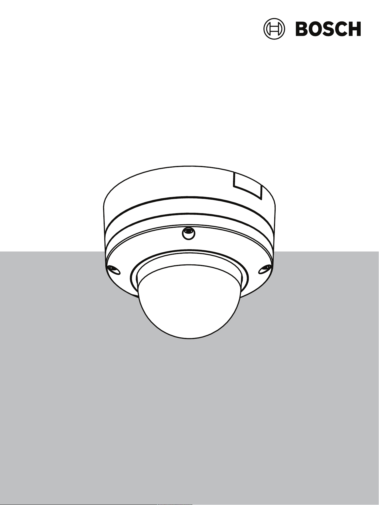
3.1 Product description
All FLEXIDOME 8100i and FLEXIDOME 8100i – X series have a unique 3-step concept for
simple installation and provide crisp, highly detailed images with the perfect balance
between high resolution and extreme low-light sensitivity (up to 4K ultra HD with starlight
and high dynamic range).
The cameras deliver incredible accuracy in high security applications and interpret captured
data for smart decision-making that goes beyond security with state-of-the-art intelligent
video analytics.
3.2 Intended use
The camera is designed to be integrated in professional IP video surveillance solutions as a
surveillance camera. Installation, commissioning and operation of the camera shall be
carried out by trained professionals only.
The use of surveillance cameras is restricted by national laws and regulations. Use the
camera accordingly.
FLEXIDOME 8100i | FLEXIDOME 8100i — X series Preparing for installation | en 9
Bosch Security Systems, BV
Installation manual
2024-11 | V01 | F.01U.411.088
4 Preparing for installation
4.1 Unpacking
This equipment should be unpacked and handled with care. If an item appears to have been
damaged in shipment, notify the shipper immediately.
Verify that all parts are included. If any items are missing, notify your Bosch Security
Systems sales or customer service representative.
The original packaging is the safest container in which to transport the unit and can be used
if returning the unit for service.
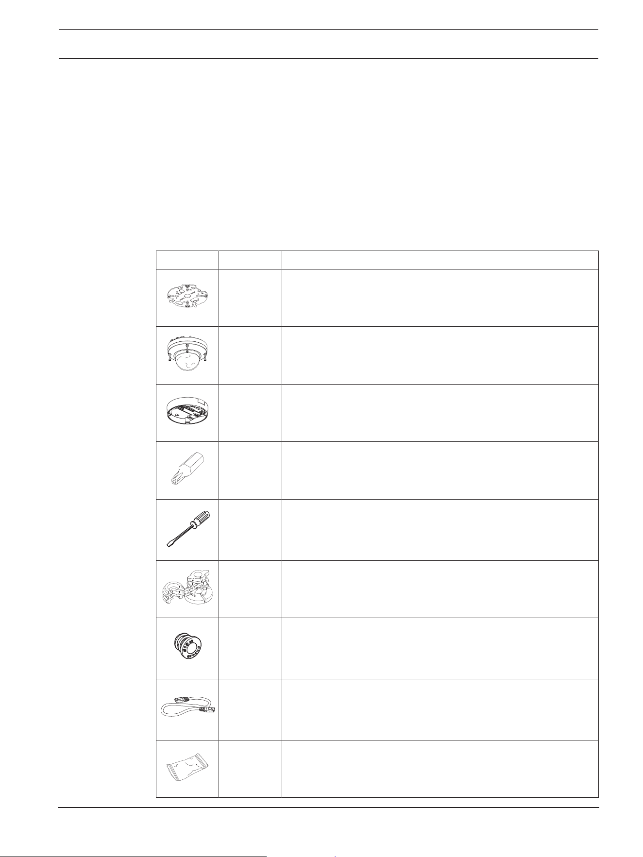
4.2 Parts included
Quantity Component
1 Mounting plate
1 Camera module
1 Camera base
1 T-20 security Torx bit
1 Mini screwdriver
1 IP66 rubber grommet
1 IP67 grommet
1 Network patch cable 50cm
1 Desiccant bag
Note: Do not open the bag before it is necessary to use its
content.
10 en | Preparing for installation FLEXIDOME 8100i | FLEXIDOME 8100i — X series
2024-11 | V01 | F.01U.411.088
Installation manual
Bosch Security Systems, BV
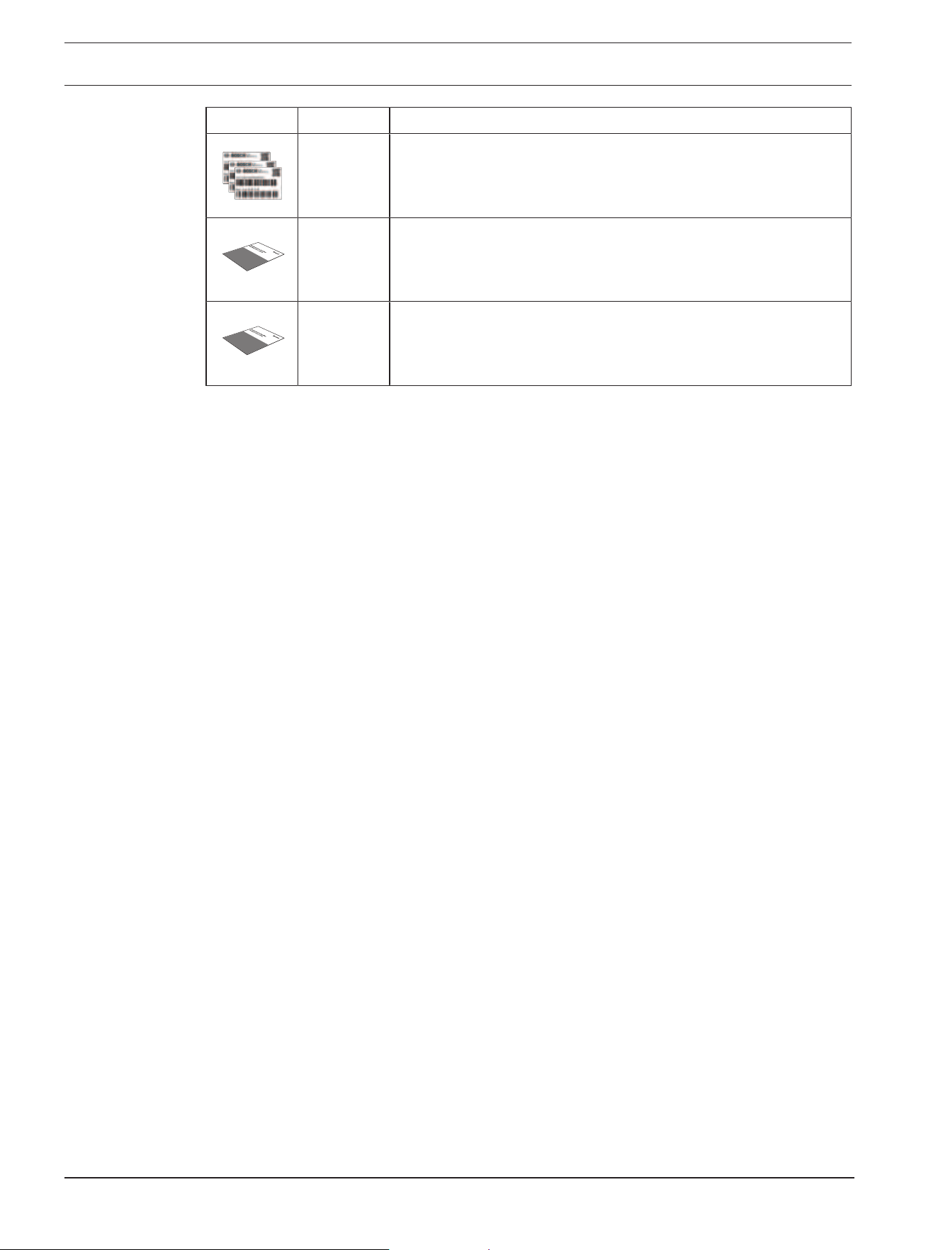
Quantity Component
3 Identification label stickers
1 Quick installation guide
1 Safety and security information
4.3 Preparation
Before installation, prepare and plan the installation process and materials needed.
Pre-requisites
Remove the components from the box. Make sure that all parts are included and are not
damaged.
The necessary material and equipment:
– Appropriate size power drill.
– Screwdriver for TR20 bit, or use a torque wrench TR20 hex key.
– microSD card (optional)
Note: Bosch recommends the use of industrial microSD cards with health monitoring.
FLEXIDOME 8100i | FLEXIDOME 8100i — X series Preparing for installation | en 11
Bosch Security Systems, BV
Installation manual
2024-11 | V01 | F.01U.411.088
4.4 Wiring
1
3
2
1 10-pin I/O connector
2 2-pin 24VAC / 12-26VDC power input connector
3 RJ45 network connector
4.4.1 Network and PoE power
Connect the camera to a 10/100/1000 Base-T network:
– Use STP Category 5e (or higher) cable with RJ45 connectors (the camera network
socket is AutoMDIX compliant).
– Power can be supplied to the camera via the Ethernet cable compliant with the Power-
over-Ethernet standard and/or via the 24VAC / 12-26VDC auxiliary power.
i
Notice!
Use only PoE approved devices.
Power-over-Ethernet (PoE) can be connected at the same time as a 24VAC / 12-26VDC
power supply. If auxiliary power (24VAC / 12-26VDC) and PoE is applied simultaneously,
the camera draws its power from PoE by default, and seamlessly switches to auxiliary input
if PoE power fails.
When PoE power returns, the camera seamlessly switches back to PoE as its default power
source.

12 en | Preparing for installation FLEXIDOME 8100i | FLEXIDOME 8100i — X series
2024-11 | V01 | F.01U.411.088
Installation manual
Bosch Security Systems, BV
4.4.2 24V AC/12-26V DC power input
Connect a SELV-LPS or a SELV Class2 power supply with a rated supply voltage of 24VAC
or 12-26VDC.
i
Notice!
When using a 24VAC power supply, do not make a ground connection with one of the
24VAC supply leads. This will damage the camera.
4.4.3 10-pin I/O connector
Pin Connection
1 ALARM OUT
2 ALARM OUT
3 GND
4 ALARM IN 1
5 ALARM IN 2
6 GND
7 AUDIO IN
8 AUDIO OUT
9 +12V OUT
10 GND
12VDC power output
The 12VDC output can be enabled/disabled via the web interface, and controlled via the
Alarm Task Editor.
Maximum load of 50mA.
i
Notice!
For best performance in extremely cold environment installations, connect 12VDC/24VAC
auxiliary power to the camera.
Alarm I/O
1. Input:
Use the alarm input to connect external alarm devices such as door contacts or
sensors:
– TTL logic, +5V nominal, +40VDC maximum, DC coupled with 50kOhm pull-up to
+3.3V.
– Configurable as active low or active high.
Use a zero potential make-contact or switch as the actuator (with a bounce-free contact
system).
2. Output:
Use the alarm output for switching external devices such as lamps or sirens. The alarm
output switching capability has a maximum voltage of 30VAC or +40VDC; maximum
0.5A continuous, 10VA.

FLEXIDOME 8100i | FLEXIDOME 8100i — X series Preparing for installation | en 13
Bosch Security Systems, BV
Installation manual
2024-11 | V01 | F.01U.411.088
Audio I/O
Connect audio devices to the audio input and audio output connectors.
The unit has full-duplex mono audio for two-way communication between a speaker or door
intercom system. The audio input signal is transmitted in synchronization with the video
signal.
1. Input:
– Line In: Line level input
– Microphone: Microphone level input with 2.5VDC (4mA) supply voltage for external
microphone
2. Output:
Line output level (not suitable for direct speaker connection); impedance 1.5kOhm
minimum; 0.85Vrms maximum output voltage.
Use shielded audio connection cable with advised maximum cable lengths for audio line
input and output levels.
4.4.4 Grounding
The camera does not need a safety earth connection, but grounding is recommended for
outdoor applications.
Grounding provides improved surge protection (up to 2kV, 2 kA to ground (8/20 µs pulse)).
The grounding wire is not included in the box. Bosch recommends the use of a grounding
wire with a ring terminal.
The ring terminal must not have a thickness greater than 2mm (0.01in.).
i
Notice!
Use proper surge protection on cables that are routed outdoors, or close to large inductive
loads or electrical mains supply cables.

14 en | In-box configuration FLEXIDOME 8100i | FLEXIDOME 8100i — X series
2024-11 | V01 | F.01U.411.088
Installation manual
Bosch Security Systems, BV
5 In-box configuration
In-box configuration of the camera can be done via a wired connection with the camera still
inside the box, by using a mobile device or PC.
1. Connect a network cable with PoE, and wait 1 minute for the camera to power up.
2. Connect and configure the camera via a wired network, using the Project Assistant app,
the Configuration Manager or the web interface.
For more detail about the Project Assistant app, refer to Commissioning.
i
Notice!
The provided patch cable is only intended for in-box configuration. Dispose of the patch
cable after the in-box configuration is successfully completed.
FLEXIDOME 8100i | FLEXIDOME 8100i — X series Hardware installation | en 15
Bosch Security Systems, BV
Installation manual
2024-11 | V01 | F.01U.411.088
6 Hardware installation
!
Caution!
Do not remove the bubble to move the camera lens manually.
The lens system is motorized for easy commissioning. Moving these parts manually will
break the gears and damage the camera. In order to move or focus the camera lens, always
use the motorized PTRZ controls mentioned in this manual. Removal of the bubble is only
allowed for bubble replacement.
Installation overview
The installation of the camera follows these steps:
1. Installing the mounting plate.
2. Installing the camera base.
3. Installing the camera module.
i
Notice!
For better results, ceiling mounts are recommended.
6.1 Installing the mounting plate
The mounting plate is used to fix the camera to a flat surface. It offers different holes and
slots for a variety of fixing options.
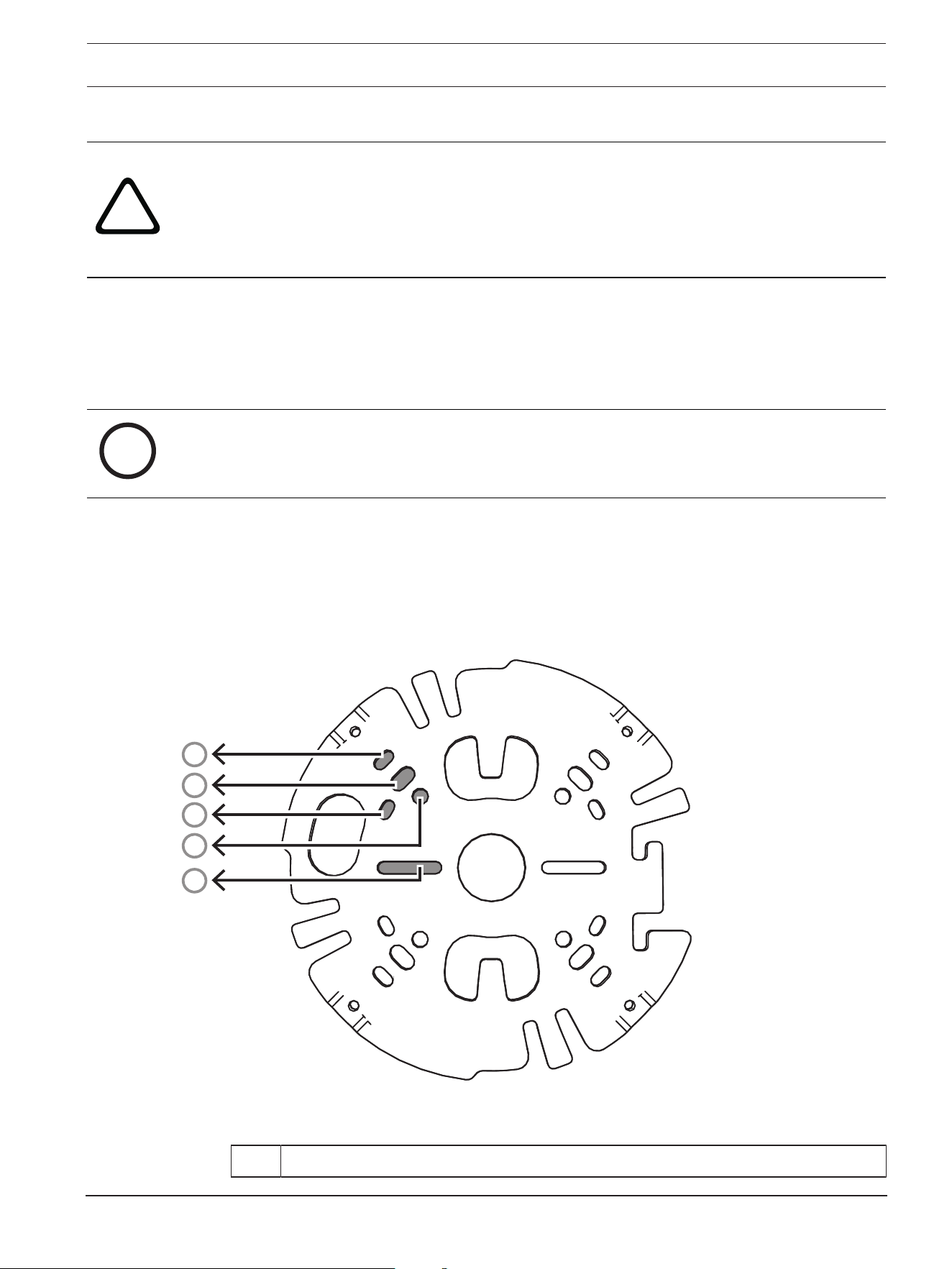
1
2
3
4
5
1 10.2cm / 4in. Square junction box
16 en | Hardware installation FLEXIDOME 8100i | FLEXIDOME 8100i — X series
2024-11 | V01 | F.01U.411.088
Installation manual
Bosch Security Systems, BV
2 Pole mount (NDA-U-PMAL/NDA-U-PMAS)/Corner mount (NDA-U-CMA)
3 Single gang box or universal slot, 45mm / 1.8in to 85mm/3.3in
4 Double gang box
5 Ceiling/wall mount and pendant interface plate (NDA-8000-PIP(W))
Note: Only options 1, 2, and 5 maintain IK11 rating.
Installation options
The camera has two configurations for surface mounting:
– Refer to Installing the mounting plate without conduit, if the wires are not on the
outside of the surface.
– Refer to Installing the mounting plate with conduit, if the wires are on the outside of
the surface.
Additionally, the camera can cover various mounting options when combined with the
available accessories. See the Mounting accessories chapter for the available accessories.
i
Notice!
The plugs and screws for surface mounting are not supplied with the camera.
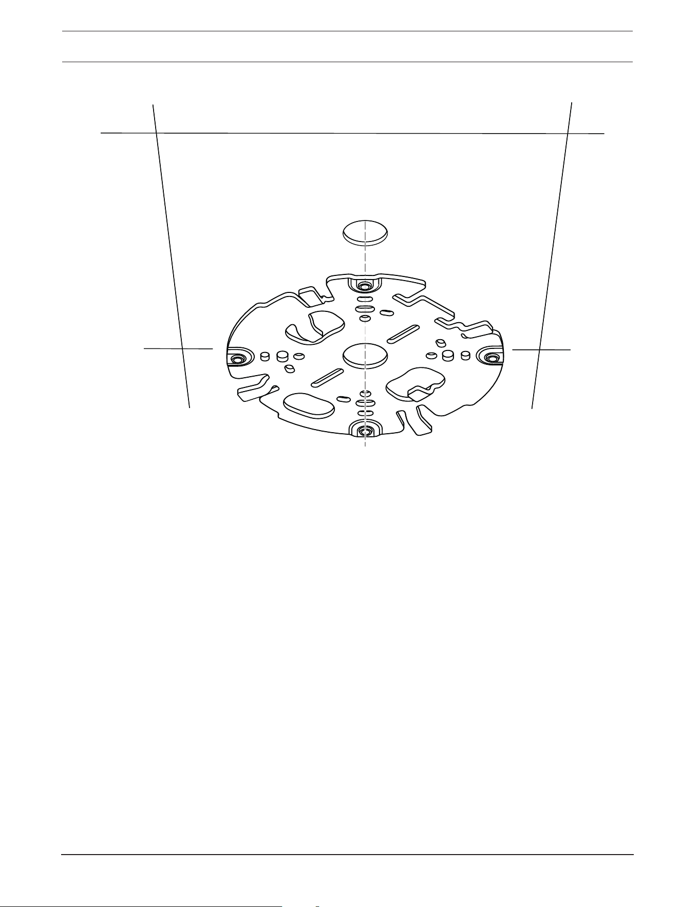
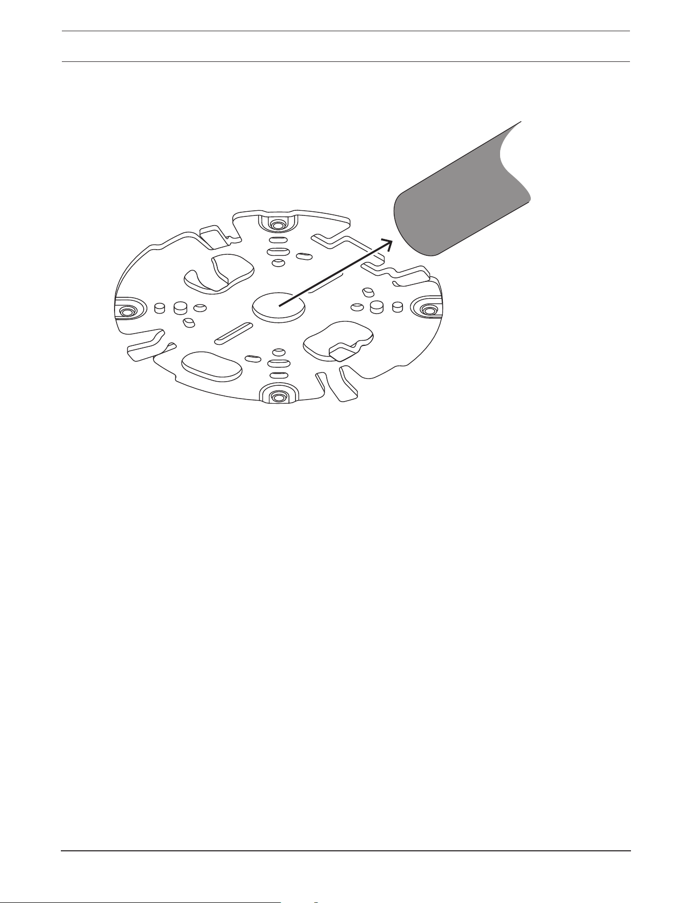
6.1.1 Installing the mounting plate without conduit
1. Remove the mounting plate from the box.
2. Position the mounting plate with the center hole on top of the cable exit on the
surface, and mark the positions of the screw holes on the surface.
FLEXIDOME 8100i | FLEXIDOME 8100i — X series Hardware installation | en 17
Bosch Security Systems, BV
Installation manual
2024-11 | V01 | F.01U.411.088
– For a camera mounted on a wall: make sure that the mounting plate is oriented in a 90º
angle, with the holes parallel to the floor, to allow for the use of a weather protector if
necessary.
18 en | Hardware installation FLEXIDOME 8100i | FLEXIDOME 8100i — X series
2024-11 | V01 | F.01U.411.088
Installation manual
Bosch Security Systems, BV
3. Drill the 4 holes with the appropriate diameter drill to support your 5-6mm (0.2inch)
screws and plugs.
4. Install 4 plugs in the holes.
5. Put the cable through the center hole of the mounting plate.
6. Attach the mounting plate to the surface with 4 screws. Tighten the screws between 4
and 7Nm (3 and 5.2lbft).
6.1.2 Installing the mounting plate with conduit
i
Notice!
Conduit is sold separately.
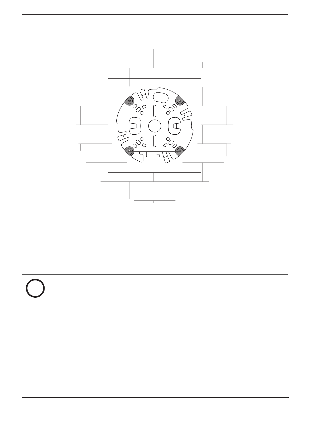
– For a camera mounted on a wall: make sure that the mounting plate is oriented in a 90º
angle, with the holes parallel to the floor, to allow for the use of a weather protector if
necessary.
FLEXIDOME 8100i | FLEXIDOME 8100i — X series Hardware installation | en 19
Bosch Security Systems, BV
Installation manual
2024-11 | V01 | F.01U.411.088
1. Remove the conduit plate from the box.
2. Mark the position of the hole on the surface.
3. Drill the hole with the appropriate diameter drill.
4. Install a plug in the hole.
5. Select the applicable conduit plate adapter and install it on the conduit plate:
– If the conduit is M25 / ¾in., use the conduit plate adapter with the larger hole
(mounted by default).
– If the conduit is M20 / ½in., use the conduit plate adapter with the smaller hole.
– If the conduit or cable diameter is smaller than M20, use the rubber adapter with
the conduit plate adapter with the larger hole. The rubber must be perforated to
put the conduit or cable through.
20 en | Hardware installation FLEXIDOME 8100i | FLEXIDOME 8100i — X series
2024-11 | V01 | F.01U.411.088
Installation manual
Bosch Security Systems, BV
6. Put the cable through the hole of the conduit plate.
7. Attach the conduit plate with the conduit plate adapter to the surface with the washer
and a 5-6 mm (0.2 in.) screw. The recommended torque is 3.25 Nm (2.39 lbft).
8. Remove the mounting plate from the box.
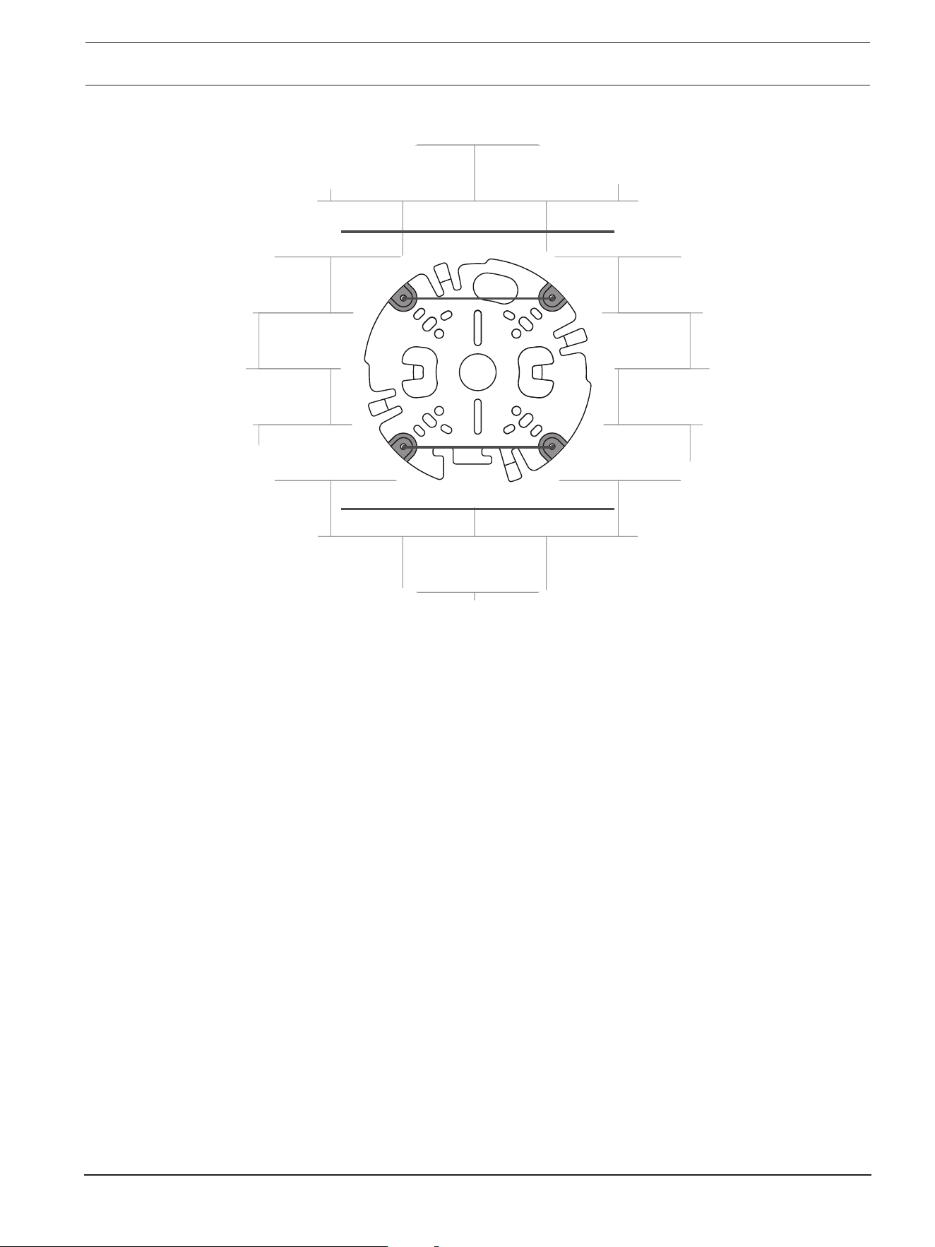
9. Mark the positions of the holes on the surface. The mounting plate has only one side
available for the conduit. Make sure to position it accordingly.
FLEXIDOME 8100i | FLEXIDOME 8100i — X series Hardware installation | en 21
Bosch Security Systems, BV
Installation manual
2024-11 | V01 | F.01U.411.088
10. Drill the 4 holes with the appropriate diameter drill to support your 5-6mm (0.2inch)
screws and plugs.
11. Install 4 plugs in the holes.
12. Attach the mounting plate to the surface with 4 screws. Tighten the screws between 4
and 7Nm (3 and 5.2lbft).
22 en | Hardware installation FLEXIDOME 8100i | FLEXIDOME 8100i — X series
2024-11 | V01 | F.01U.411.088
Installation manual
Bosch Security Systems, BV
13. Install the conduit cover on the conduit plate with the bolt. Tighten the screw between
1.4 and 2Nm (1lbft and 1.5lbft).
FLEXIDOME 8100i | FLEXIDOME 8100i — X series Hardware installation | en 23
Bosch Security Systems, BV
Installation manual
2024-11 | V01 | F.01U.411.088
6.2 Installing the camera base
6.2.1 Before the installation
1. With the camera inside the box, remove the tapes from the sides of the camera base.
2. Remove the camera base from the box.
3. If it is not preferred for installation, remove the optional CAT5e patch cable (50cm /
19.7in.).
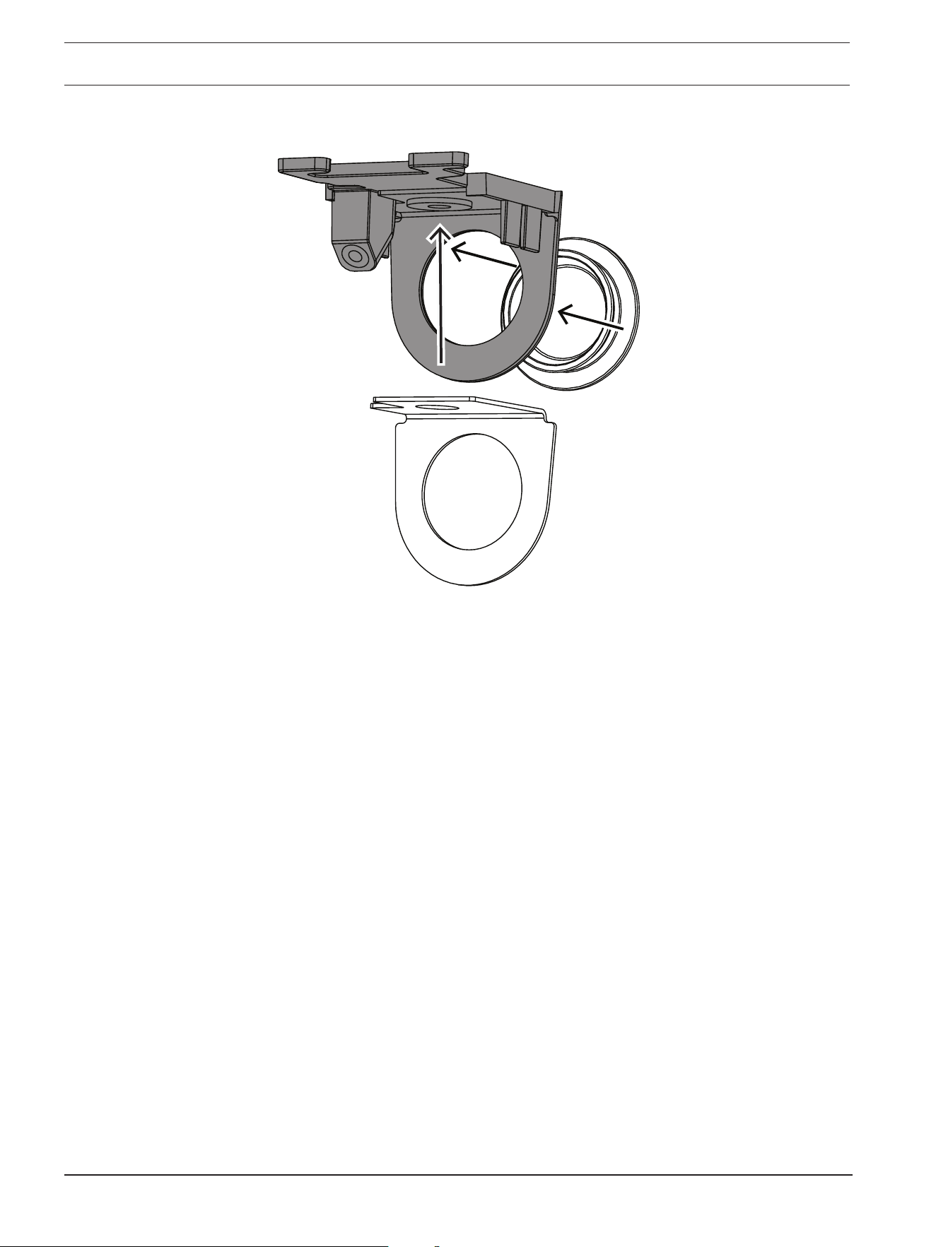
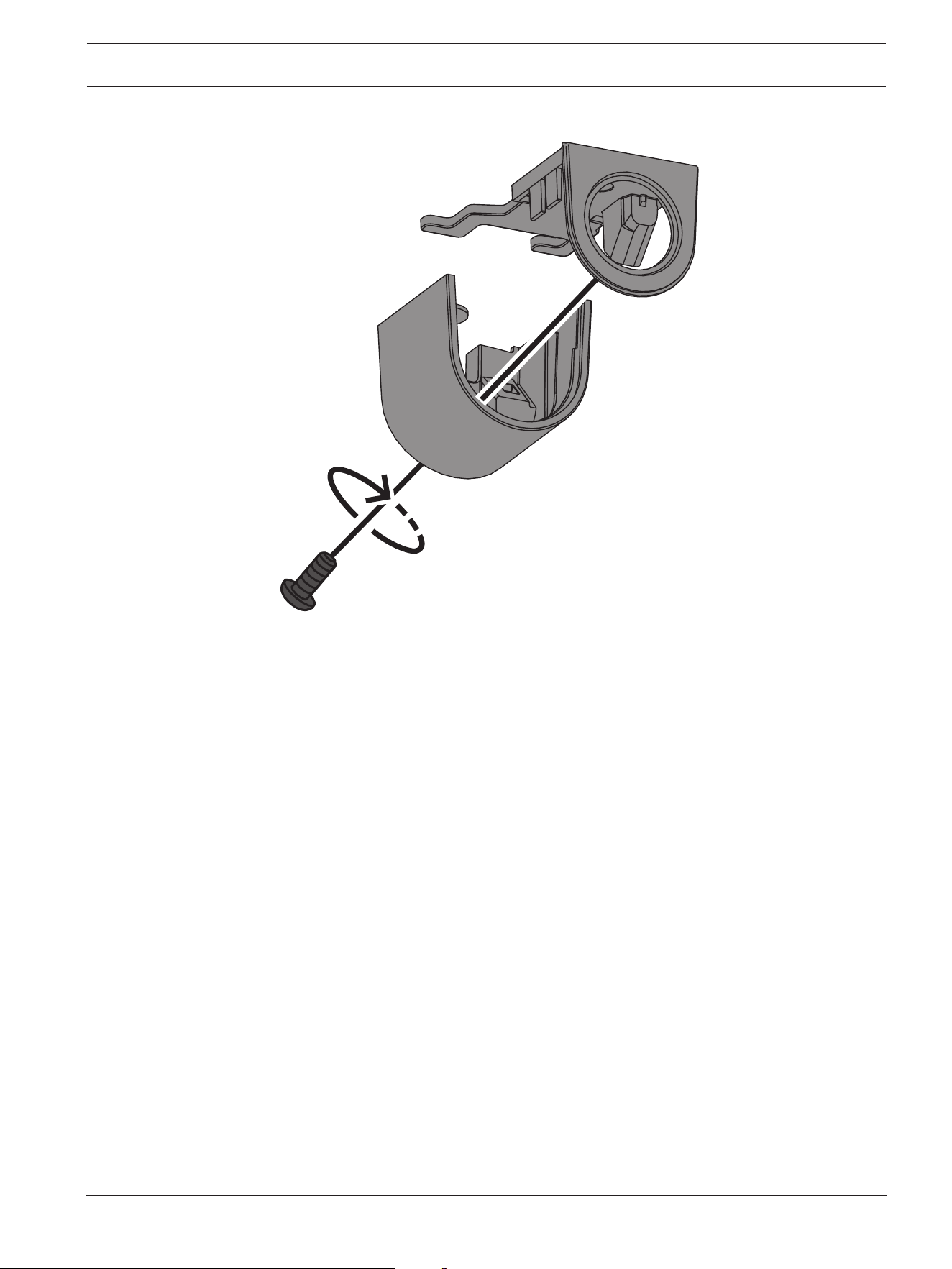
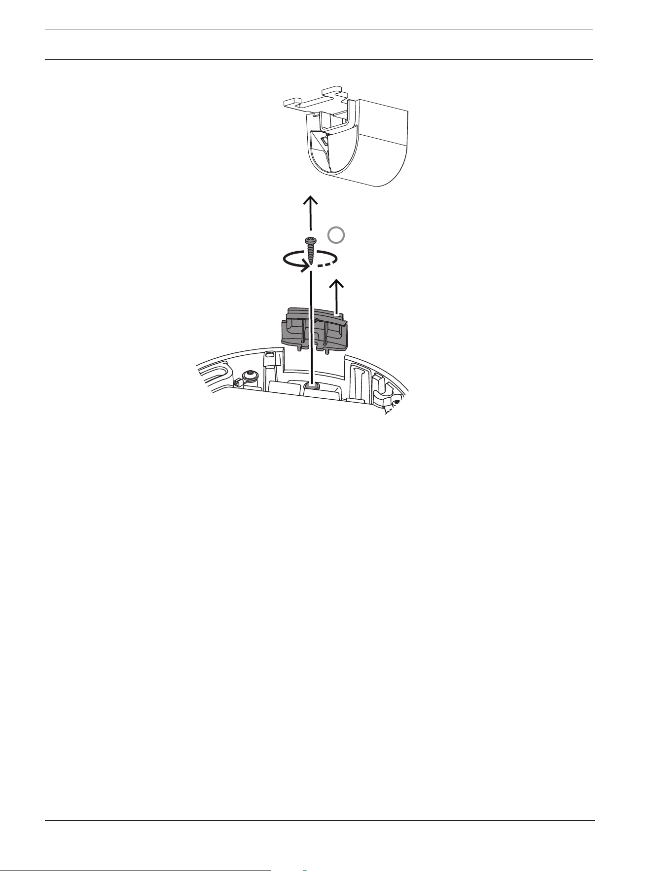
4. If the installation of the mounting plate was done with the conduit, remove the door on
the camera base as shown in the image. Keep the screw and lid.
24 en | Hardware installation FLEXIDOME 8100i | FLEXIDOME 8100i — X series
2024-11 | V01 | F.01U.411.088
Installation manual
Bosch Security Systems, BV
1
5. If there are auxiliary connections, puncture a hole in the rubber of the secondary cable
inlet (2) in the camera base to put them through. The diameter of the whole must be
between 5 and 8mm (0.2 and 0.3in.).
The network cable inlet (1) is for the network cable only.
FLEXIDOME 8100i | FLEXIDOME 8100i — X series Hardware installation | en 25
Bosch Security Systems, BV
Installation manual
2024-11 | V01 | F.01U.411.088
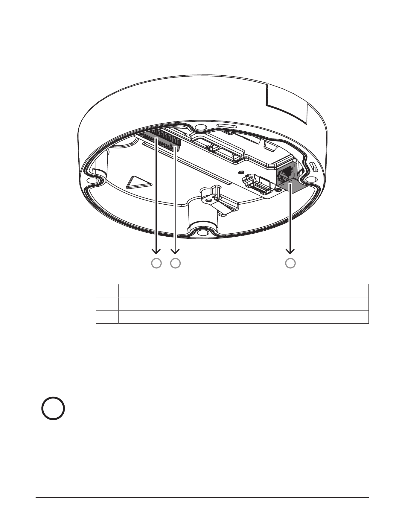
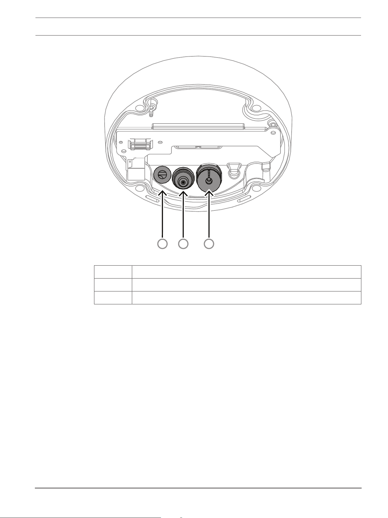
3
2
1
1 Network cable inlet.
2 Secondary cable inlet for additional cabling. It is waterproof if not in use.
3 Protective breathing vent. Do not remove or break the sealing from this hole.
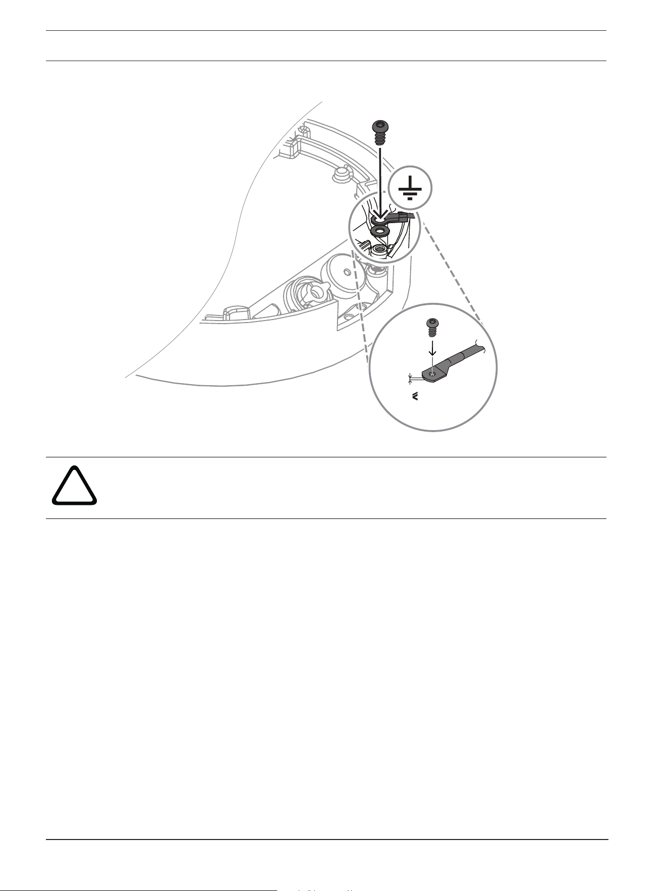
Grounding (optional)
To ground the camera:
1. Remove the screw from the bottom of the camera base.
2. Install the ring terminal on the screw.
3. Hold the camera base and attach the screw with the grounding cable.
26 en | Hardware installation FLEXIDOME 8100i | FLEXIDOME 8100i — X series
2024-11 | V01 | F.01U.411.088
Installation manual
Bosch Security Systems, BV
2 mm
0.07 in.
!
Warning!
Trained electricians only!
Work at electric appliances must only be carried out by qualified technicians.
6.2.2 Installation steps
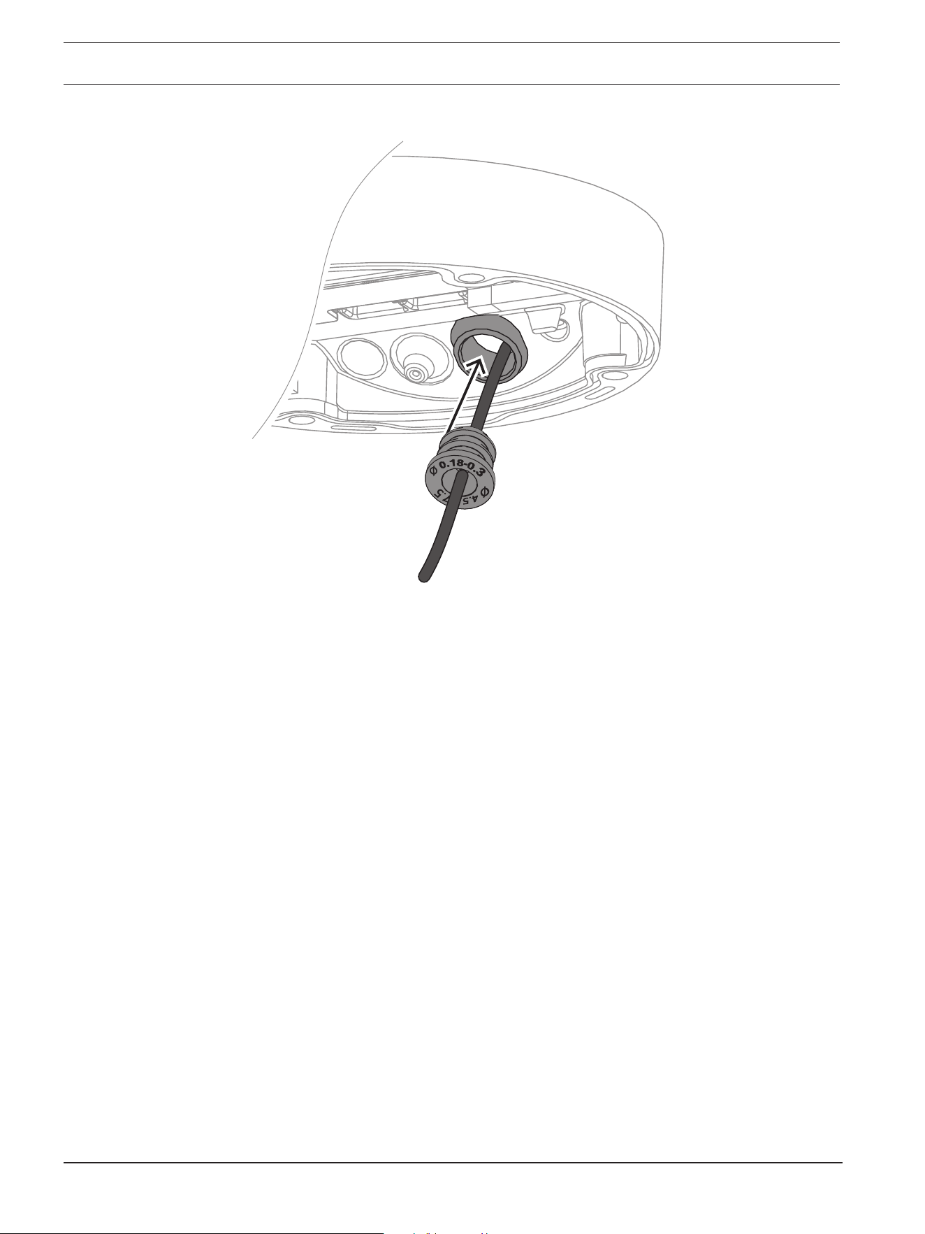
1. Put the network cable through the network cable inlet.
2. If necessary, put all auxiliary connections through the secondary cable inlet.
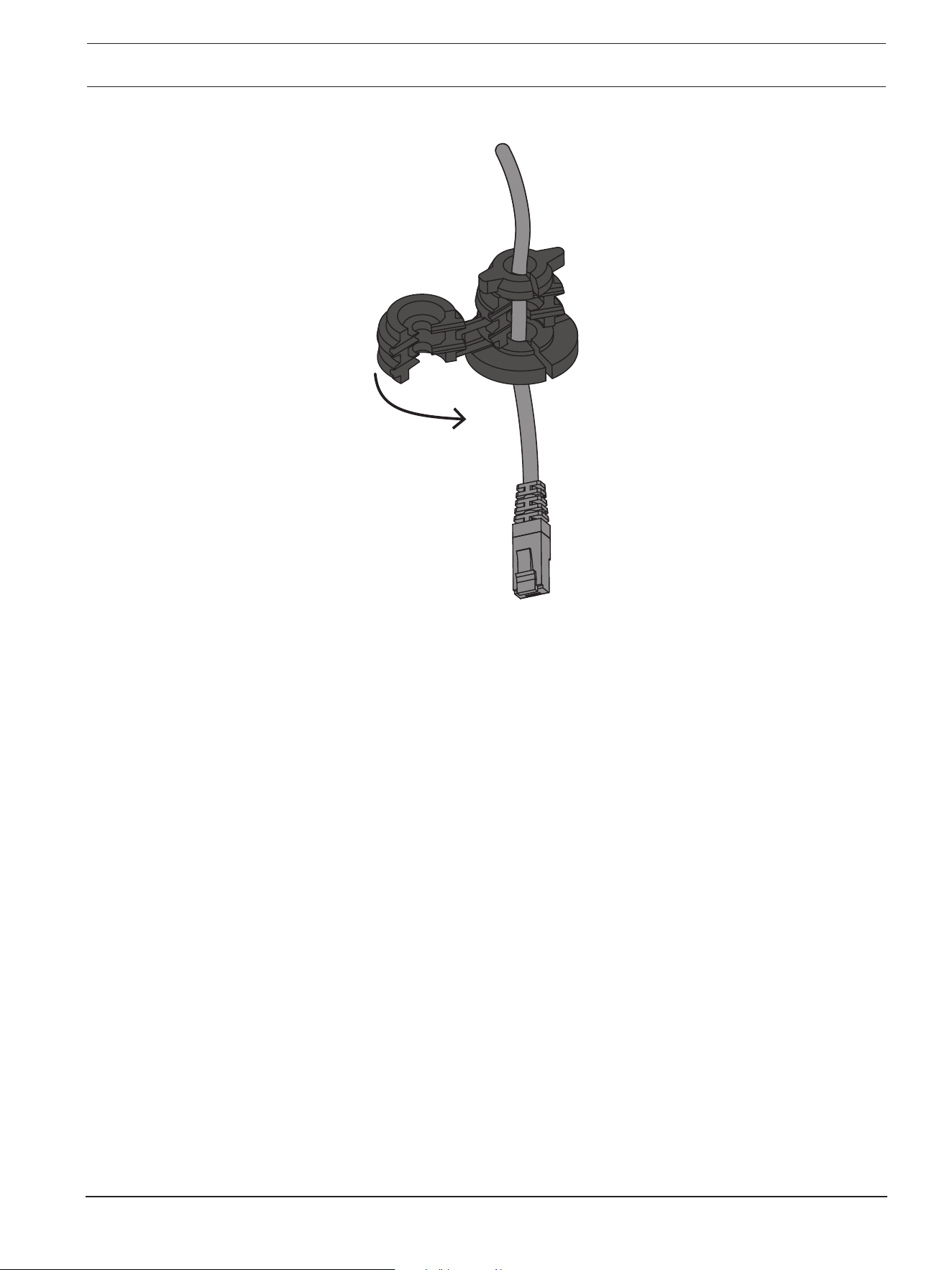
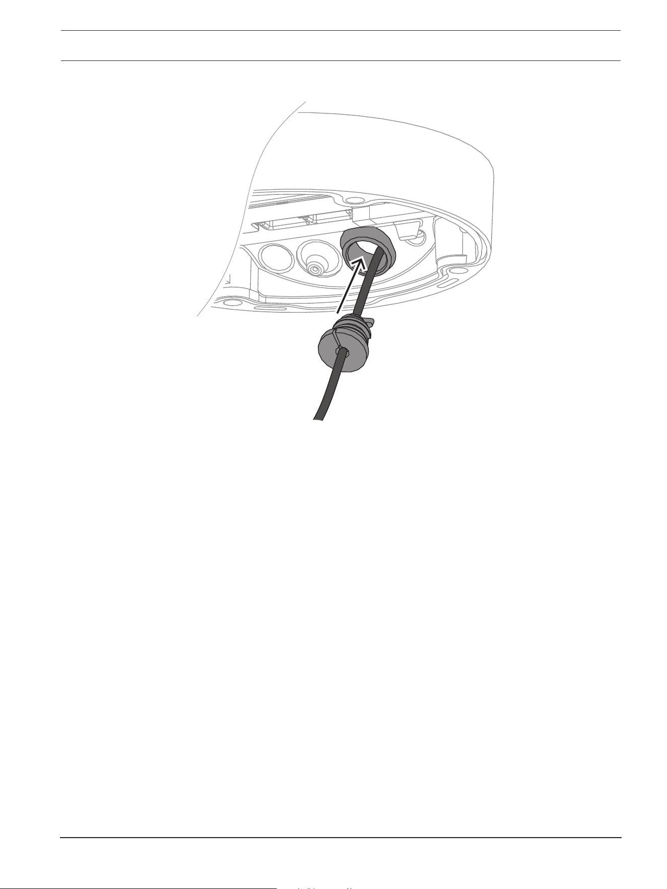
3. Attach a grommet to the network cable:
– For an RJ45 network cable, insert the IP66 grommet tightly around the cable.
FLEXIDOME 8100i | FLEXIDOME 8100i — X series Hardware installation | en 27
Bosch Security Systems, BV
Installation manual
2024-11 | V01 | F.01U.411.088
– Insert the cable through the IP67 grommet and crimp the RJ45 connector on the
network cable.
28 en | Hardware installation FLEXIDOME 8100i | FLEXIDOME 8100i — X series
2024-11 | V01 | F.01U.411.088
Installation manual
Bosch Security Systems, BV
4. Grab the camera base with both hands and push the grommet into the network cable
inlet with both thumbs on the opposite sides of the network cable.
FLEXIDOME 8100i | FLEXIDOME 8100i — X series Hardware installation | en 29
Bosch Security Systems, BV
Installation manual
2024-11 | V01 | F.01U.411.088
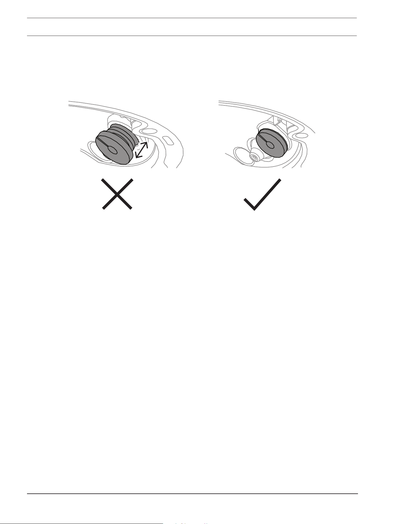
5. Make sure that the grommet is pushed in to its full length.
30 en | Hardware installation FLEXIDOME 8100i | FLEXIDOME 8100i — X series
2024-11 | V01 | F.01U.411.088
Installation manual
Bosch Security Systems, BV
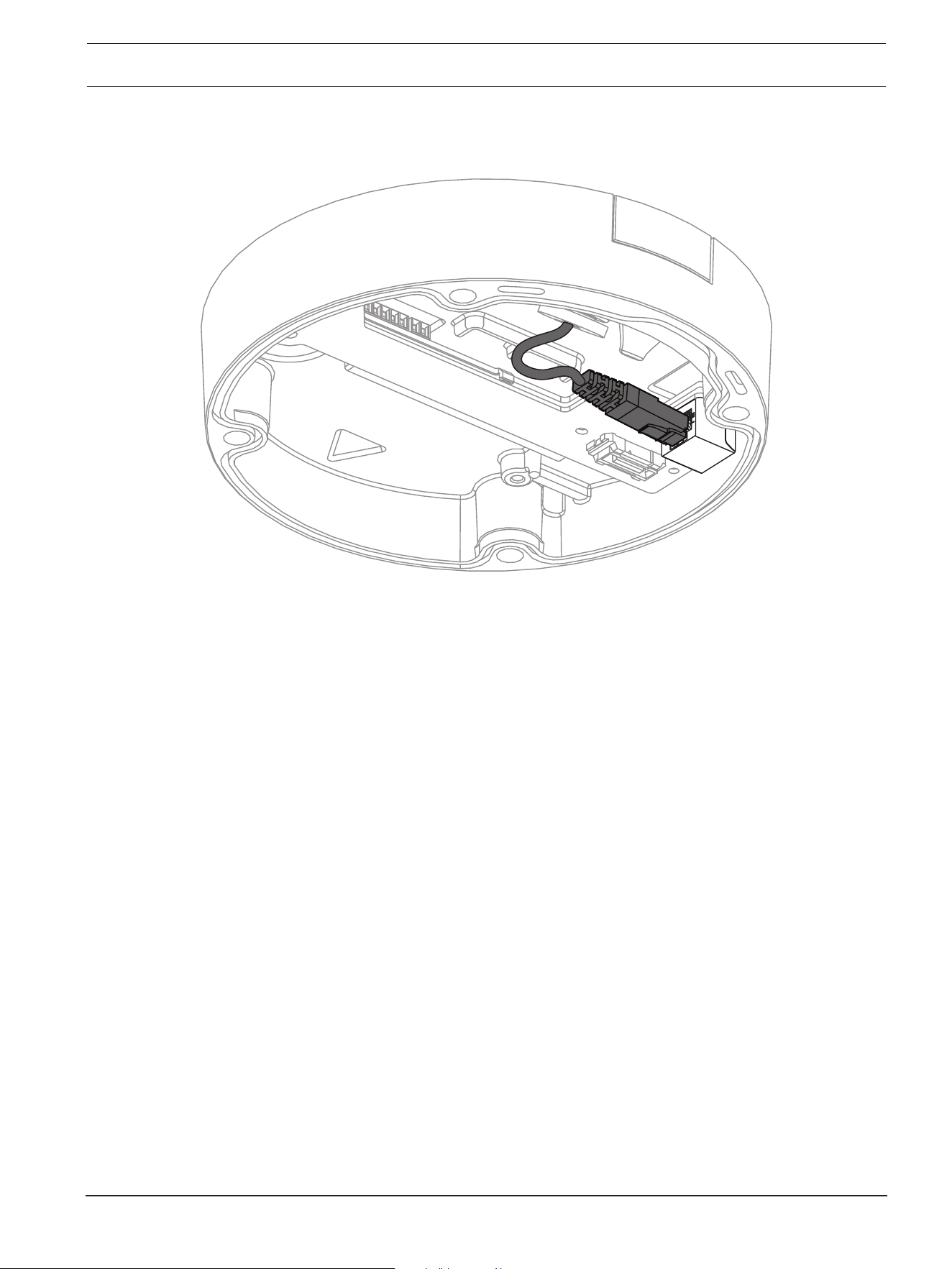
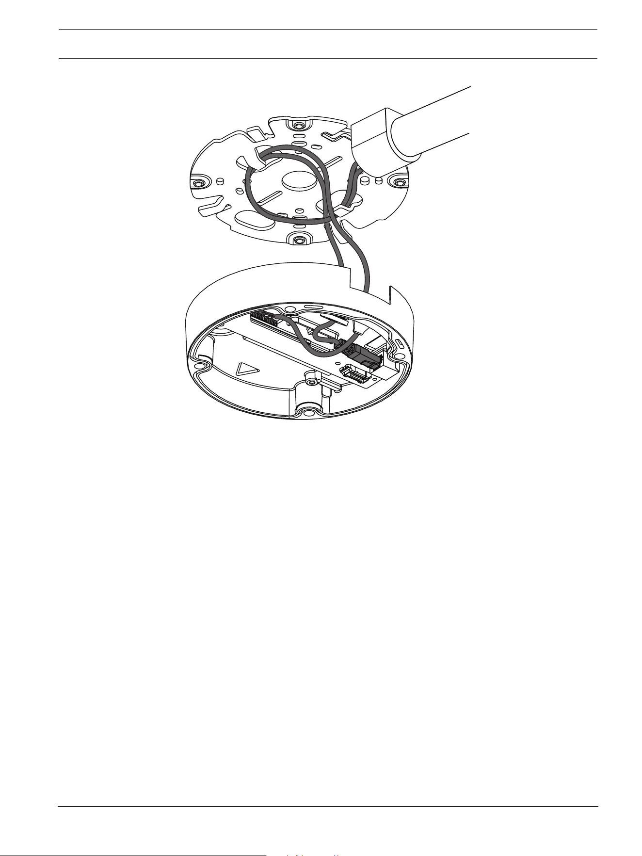
6. Adjust the length of the network cable as necessary.
7. Connect the network cable to the network connector.
FLEXIDOME 8100i | FLEXIDOME 8100i — X series Hardware installation | en 31
Bosch Security Systems, BV
Installation manual
2024-11 | V01 | F.01U.411.088
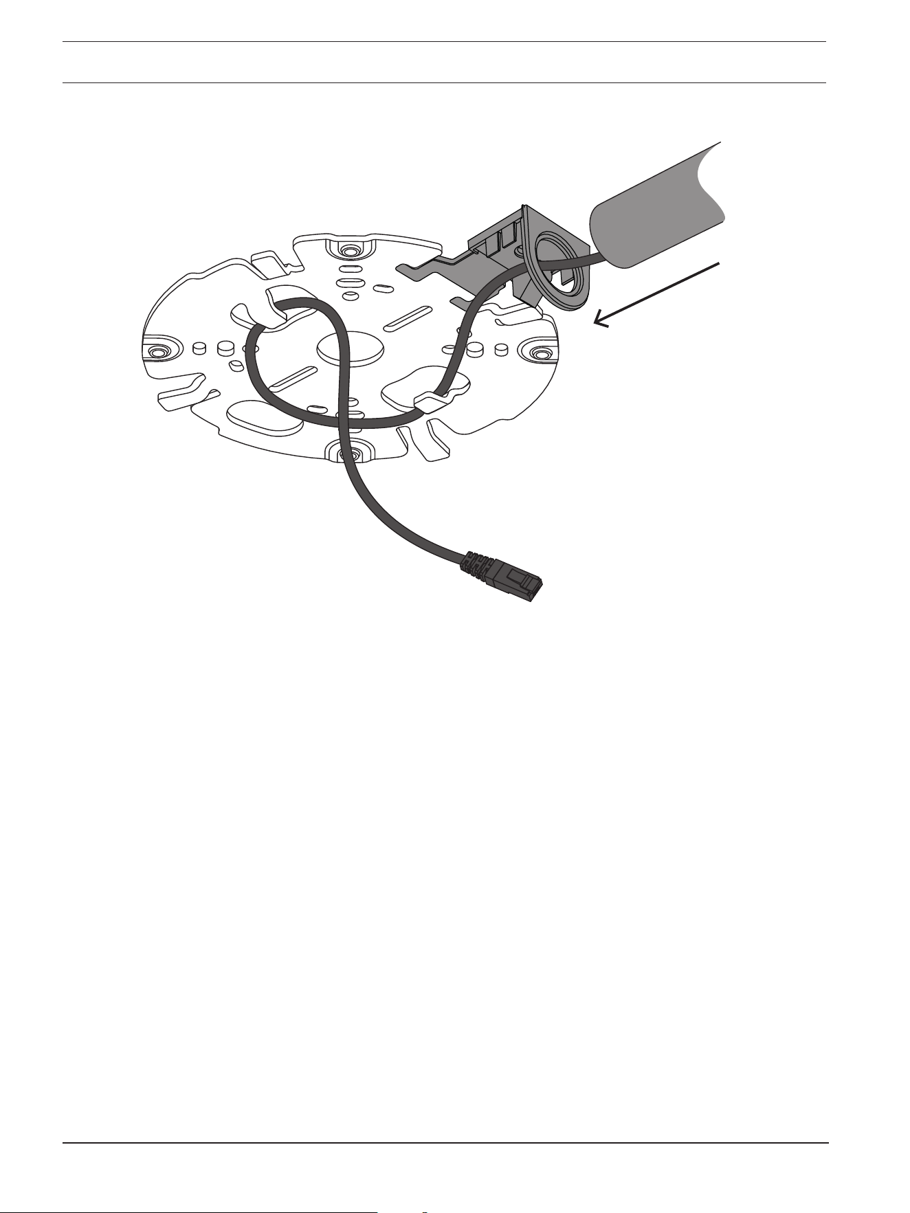
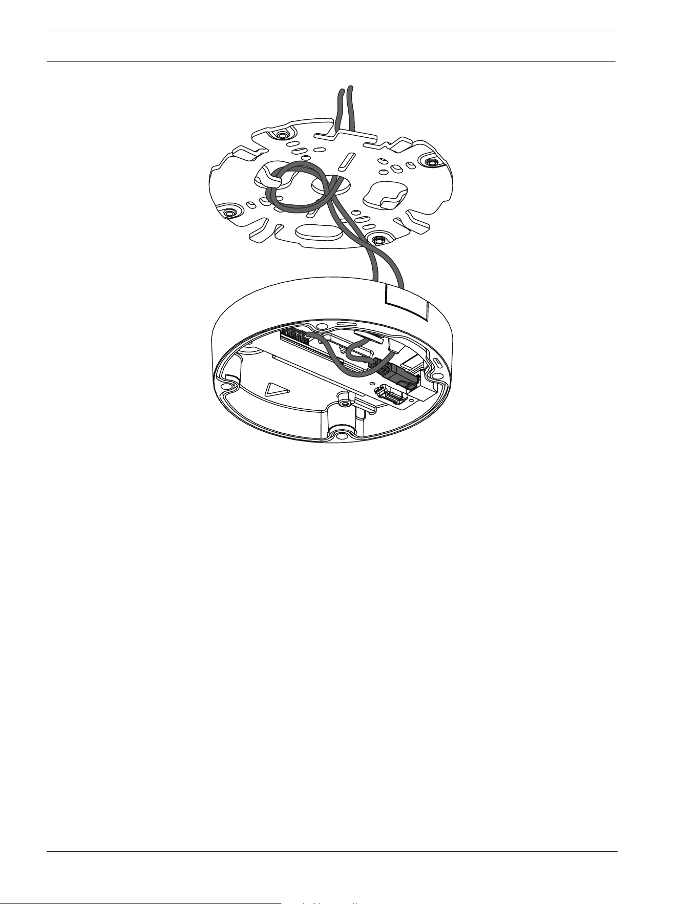
8. If required, do a loop with the cable on the hooks of the mounting plate.
– For an installation without conduit, do a loop with the cable on one of the hooks of the
mounting plate.
32 en | Hardware installation FLEXIDOME 8100i | FLEXIDOME 8100i — X series
2024-11 | V01 | F.01U.411.088
Installation manual
Bosch Security Systems, BV
– For an installation with conduit, do a loop with the cable on both hooks of the
mounting plate.
FLEXIDOME 8100i | FLEXIDOME 8100i — X series Hardware installation | en 33
Bosch Security Systems, BV
Installation manual
2024-11 | V01 | F.01U.411.088
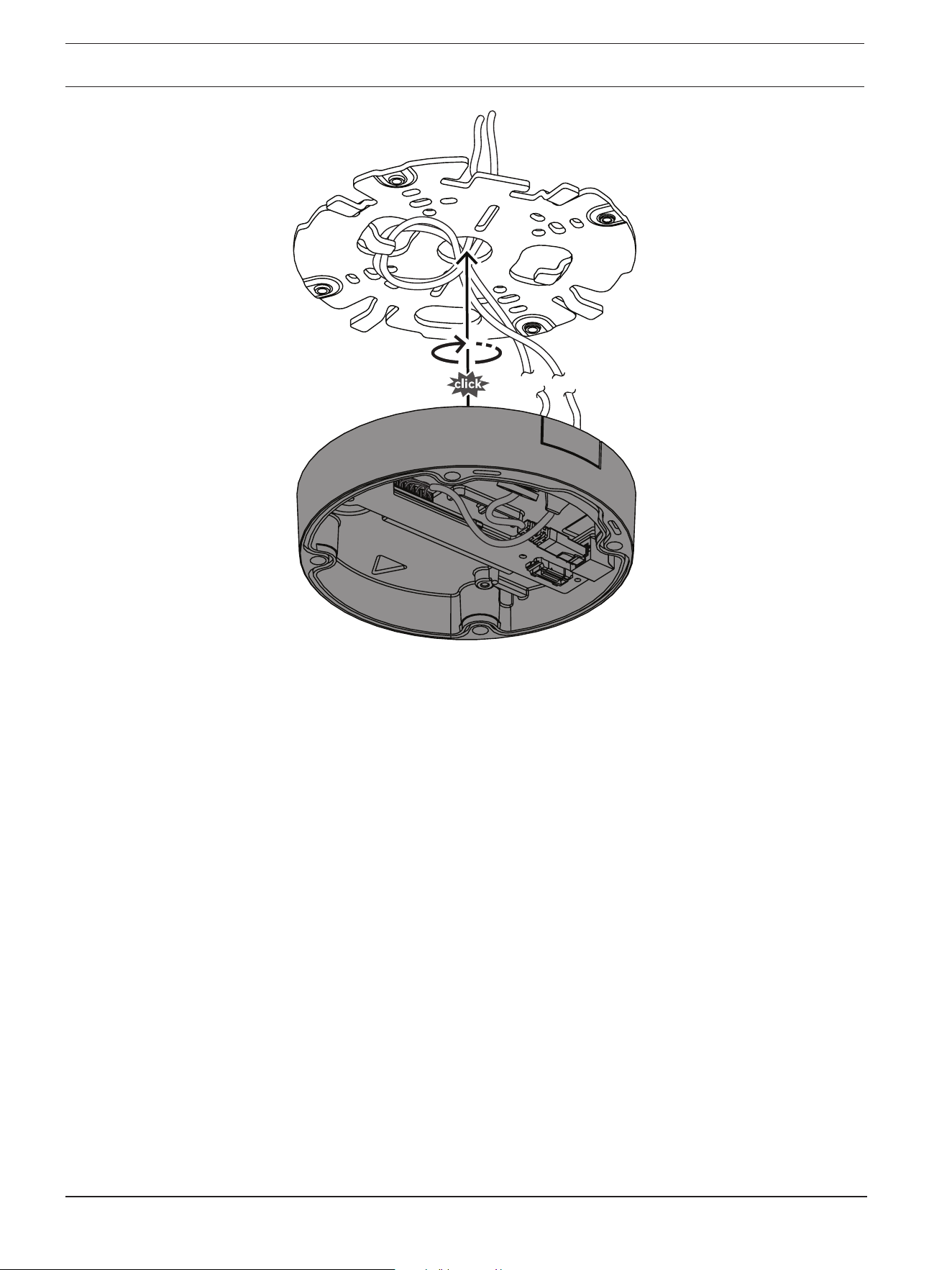
9. Push the camera base against the mounting plate and turn the camera base in the
clockwise direction until you hear/feel a click. Make sure that the camera base is
secured.
34 en | Hardware installation FLEXIDOME 8100i | FLEXIDOME 8100i — X series
2024-11 | V01 | F.01U.411.088
Installation manual
Bosch Security Systems, BV
10. If necessary, connect the auxiliary wires to the terminals supplied (refer to Wiring).
11. Connect the terminals to their related connectors.
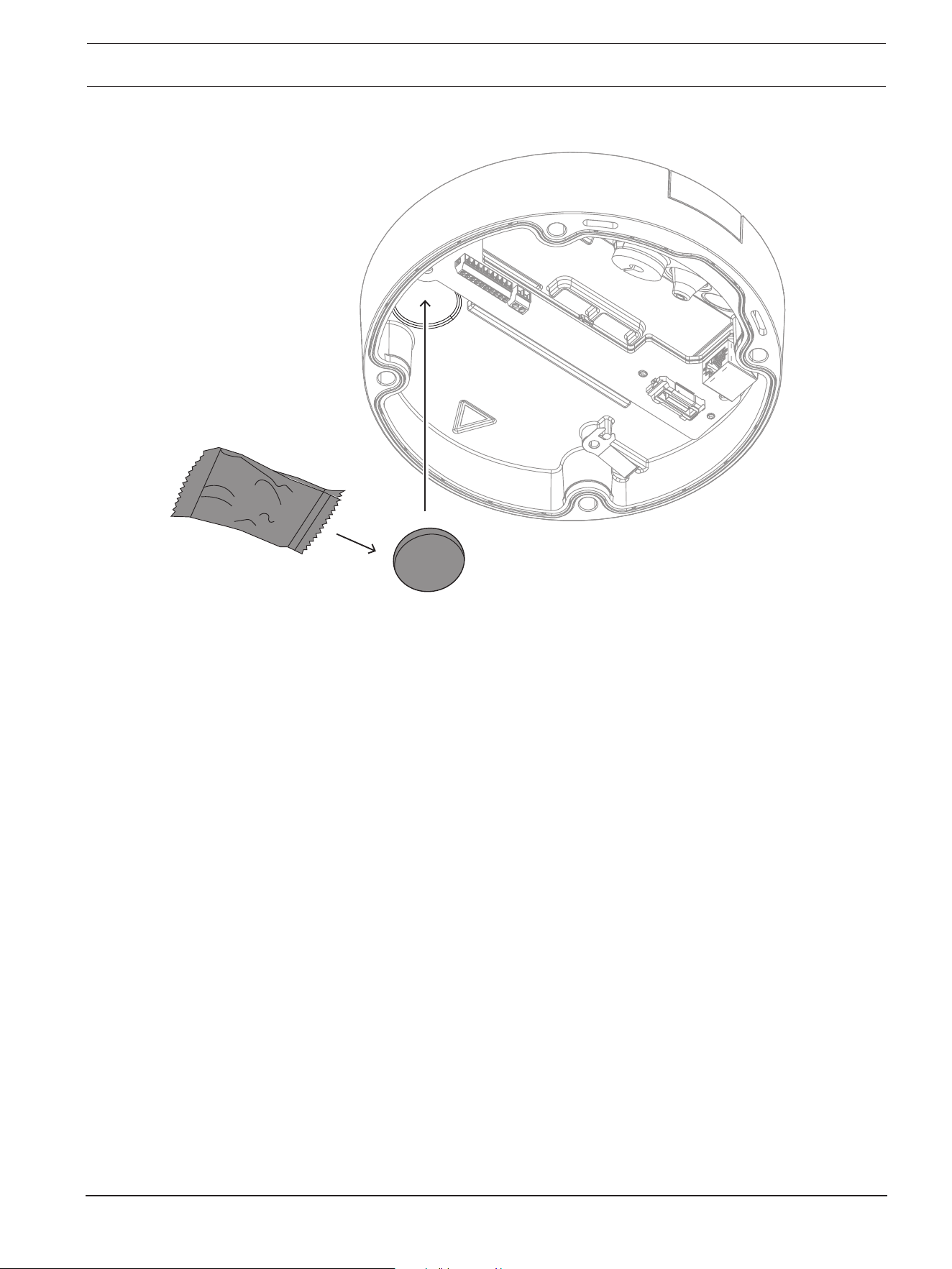
Moisture protection
1. Remove the desiccant tablet from the bag.
After removing the desiccant tablet from the bag, installation must be completed in less
than 10 minutes.
2. Attach the desiccant tablet with the adhesive side facing the camera base. Make sure
not to cover the vents with the desiccant.
FLEXIDOME 8100i | FLEXIDOME 8100i — X series Hardware installation | en 35
Bosch Security Systems, BV
Installation manual
2024-11 | V01 | F.01U.411.088
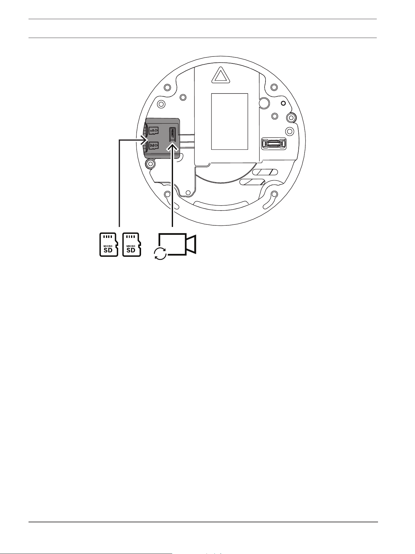
6.3 Installing the camera module
1. Remove the camera module from the box.
– If necessary, install the micro SD card in micro SD slot 1.
– Press the micro SD card firmly until it latches into place in the slot.
36 en | Hardware installation FLEXIDOME 8100i | FLEXIDOME 8100i — X series
2024-11 | V01 | F.01U.411.088
Installation manual
Bosch Security Systems, BV
Reset
– To remove the card, press it into the slot until it unlatches again.
– If more than one micro SD card is necessary, install the other micro SD card in micro
SD slot 2.
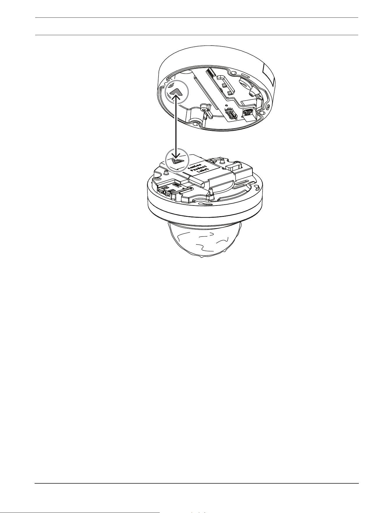
2. Attach the camera module to the camera base and tighten the four screws. The
recommended torque is 3.25Nm (2.39lbft). Make sure that the arrow on the camera
module points in the same direction as the red arrow on the camera base.
FLEXIDOME 8100i | FLEXIDOME 8100i — X series Hardware installation | en 37
Bosch Security Systems, BV
Installation manual
2024-11 | V01 | F.01U.411.088
3. Remove the protective cover from the bubble.
38 en | Hardware installation FLEXIDOME 8100i | FLEXIDOME 8100i — X series
2024-11 | V01 | F.01U.411.088
Installation manual
Bosch Security Systems, BV
4. Make sure that all necessary wiring is done, and that energy is being supplied.
6.4 LED status
The device includes a status LED. The LED can be seen in the camera bubble on the
opposite side of the camera lens.
Refer to the table below for the different status LED functions.
Status LED Meaning
Red Booting
Blinking red Resetting
Green Working, but stream is not being watched or
recorded
Blinking green Stream is being watched and/or recorded
Disable the status LED in the camera settings, if necessary.
1. Select Camera.
2. Select Installer menu.
3. Select Disabled in Camera LED.
FLEXIDOME 8100i | FLEXIDOME 8100i — X series Hardware installation | en 39
Bosch Security Systems, BV
Installation manual
2024-11 | V01 | F.01U.411.088
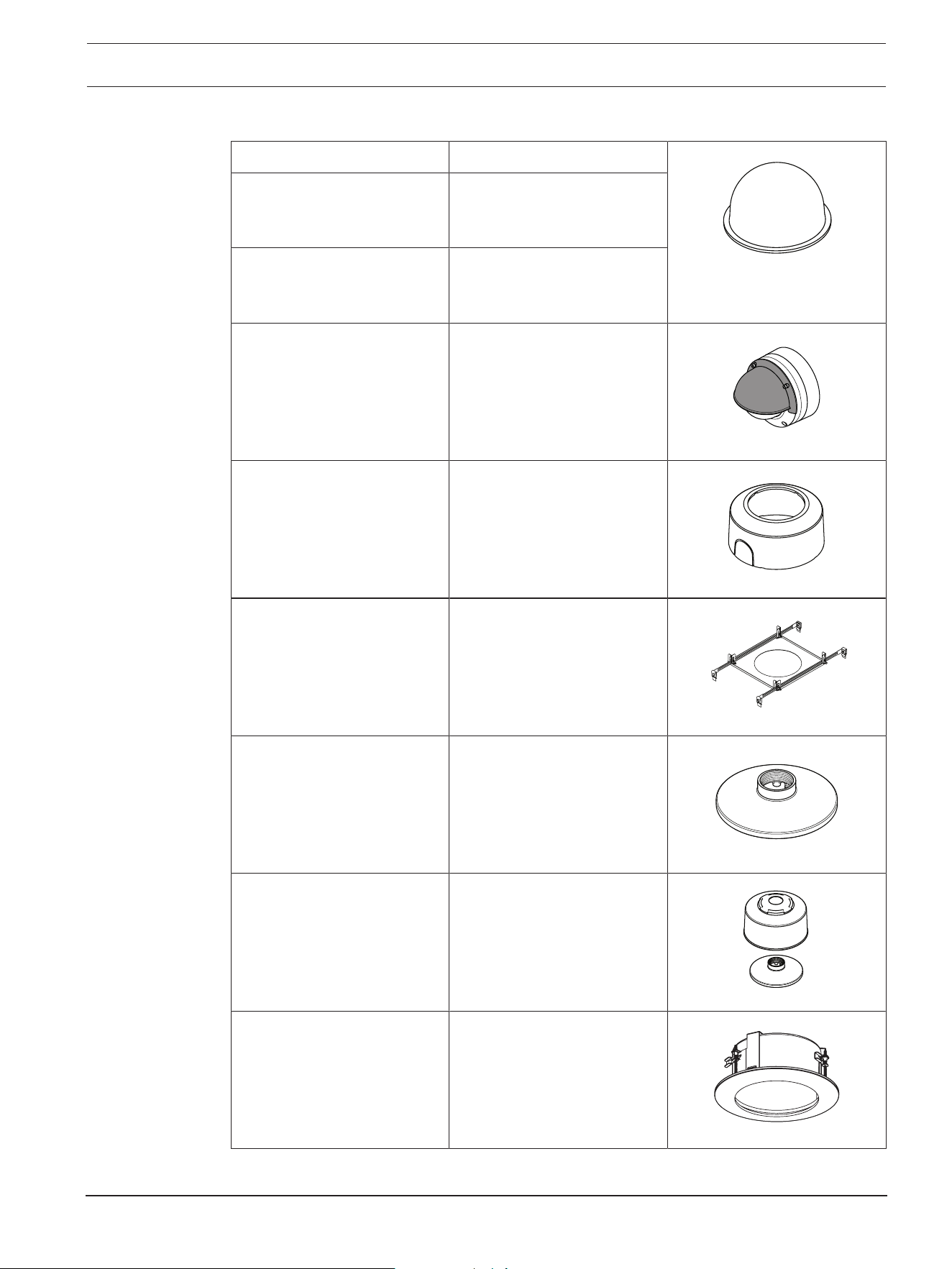
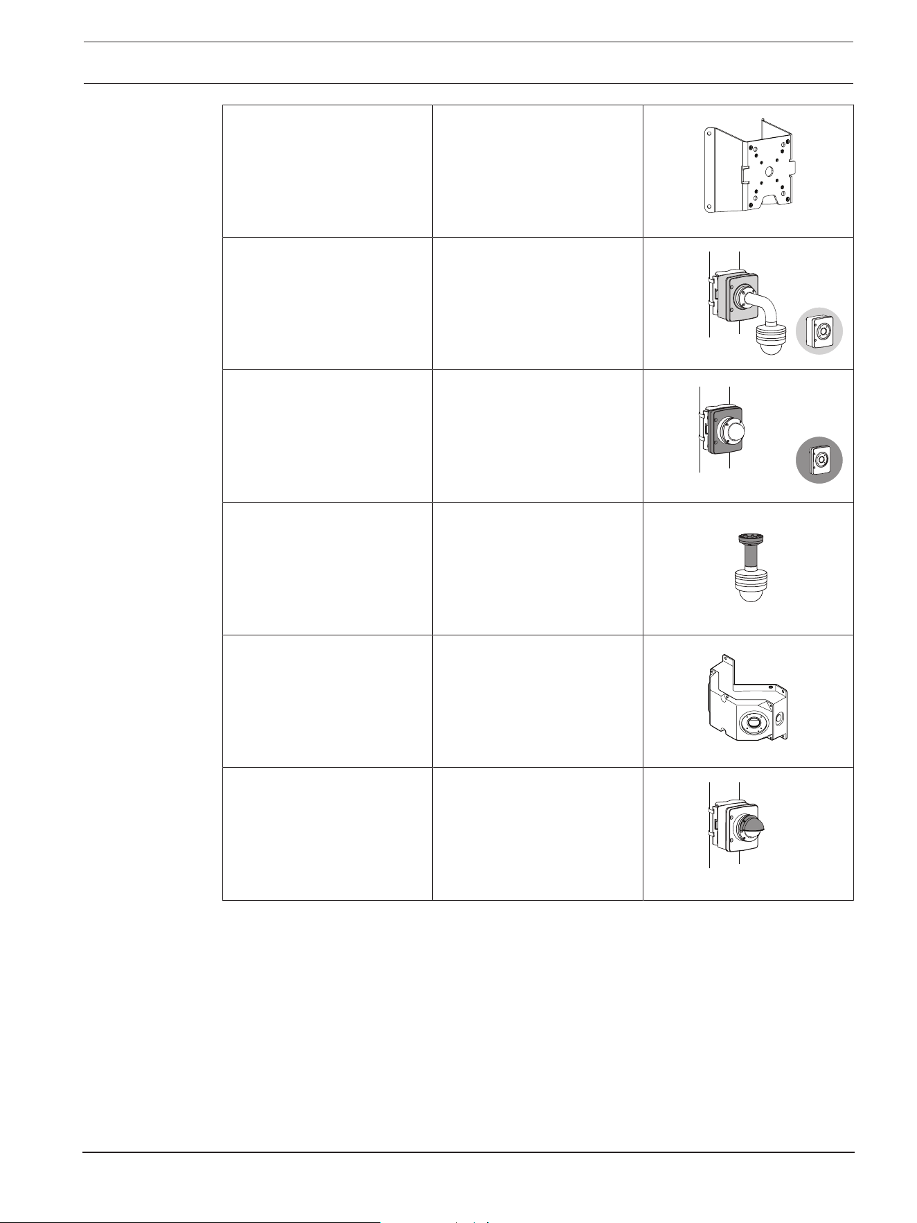
6.5 Mounting accessories
NDA-8000-CBL Clear replacement bubble
NDA-8000-TBL Tinted bubble for
FLEXIDOME IP 8000i and
FLEXIDOME 8100i cameras
NDA-8000-HCBL Hydrophilic bubble for
FLEXIDOME IP 8000i and
FLEXIDOME 8100i cameras
NDA-8000-WP On-camera weather protector
for FLEXIDOME IP 8000i and
FLEXIDOME 8100i cameras
NDA-8000-PC Paintable cover (4 pieces)
for FLEXIDOME IP 8000i.
NDA-8000-SP Soft ceiling support for in-
ceiling mount kit for
FLEXIDOME IP 8000i and
FLEXIDOME 8100i cameras
NDA-8000-PIP Pendant interface plate for
FLEXIDOME IP 8000i, indoor.
NDA-8000-PIPW Pendant interface plate
including weather protector
for FLEXIDOME IP 8000i and
FLEXIDOME 8100i cameras
NDA-8002-PLEN Plenum-rated in-ceiling
mount kit for FLEXIDOME IP
8000i and FLEXIDOME 8100i
cameras.
40 en | Hardware installation FLEXIDOME 8100i | FLEXIDOME 8100i — X series
2024-11 | V01 | F.01U.411.088
Installation manual
Bosch Security Systems, BV
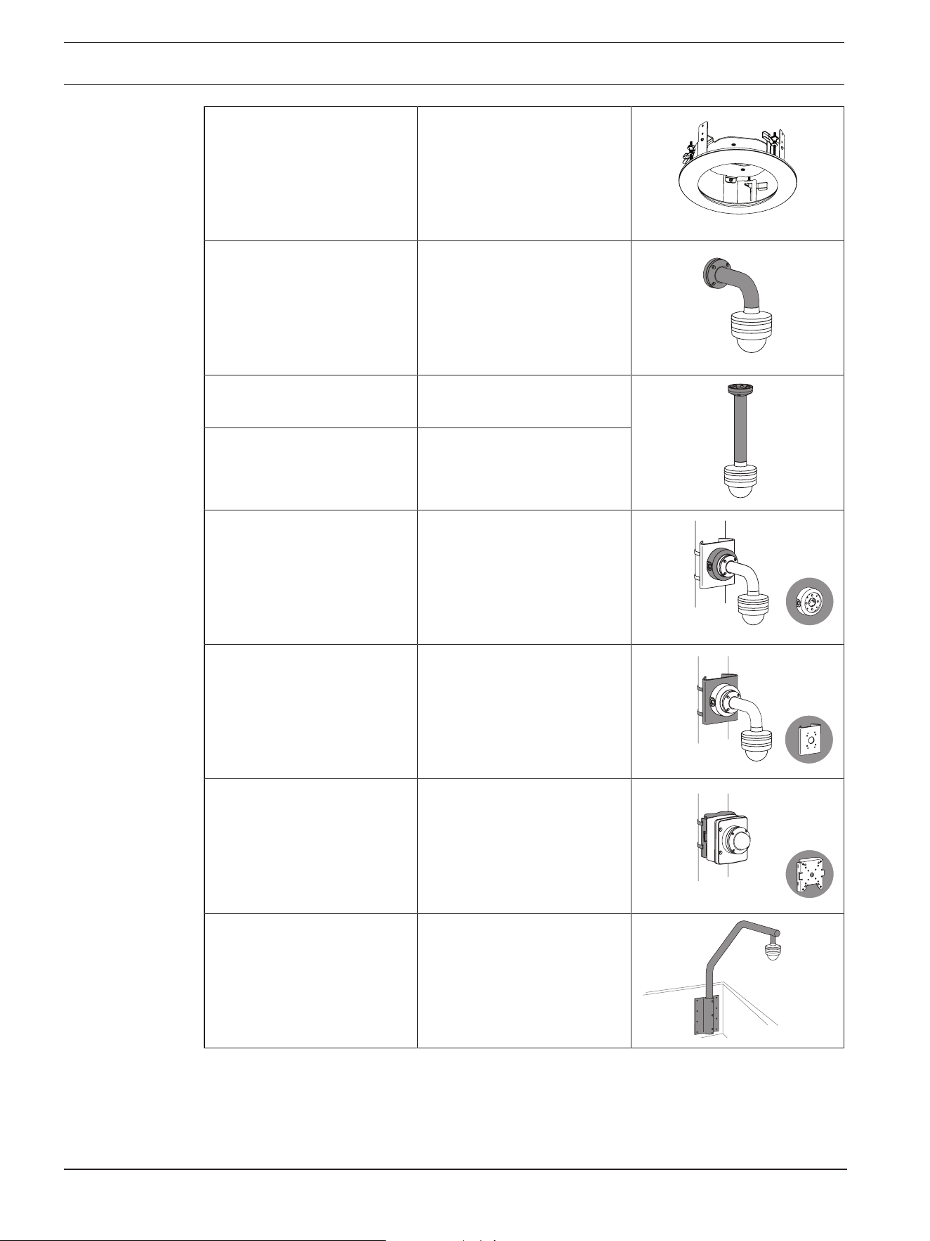
NDA-8002-IC In-ceiling mount kit with
microphone support for
FLEXIDOME IP 8000i and
FLEXIDOME 8100i cameras.
NDA-U-WMT Universal wall mount for
dome cameras, white.
NDA-U-PMT Universal pipe mount for
dome cameras, 31 cm, white.
NDA-U-PMTE Extension for universal pipe
mount, 50 cm, white
NDA-U-PSMB Surface mount box (SMB) for
wall mount or pipe mount.
NDA-U-PMAS Universal pole mount
adapter, white; small.
NDA-U-PMAL Universal pole mount
adapter, white; large.
NDA-U-RMT Universal roof mount for
dome cameras, white.
FLEXIDOME 8100i | FLEXIDOME 8100i — X series Hardware installation | en 41
Bosch Security Systems, BV
Installation manual
2024-11 | V01 | F.01U.411.088
NDA-U-CMT Universal corner mount,
white
NDA-U-PAx Surveillance cabinet
NDA-U-WMP Back plate for universal wall
mount, corner mount and
pole mount, white, IP66
NDA-U-PMTS Universal pendant pipe
mount for dome cameras,
11cm (4"), white
NDA-U.DWMT Universal dual wall mount for
dome cameras
NBA-7070-PAx Surveillance cabinet
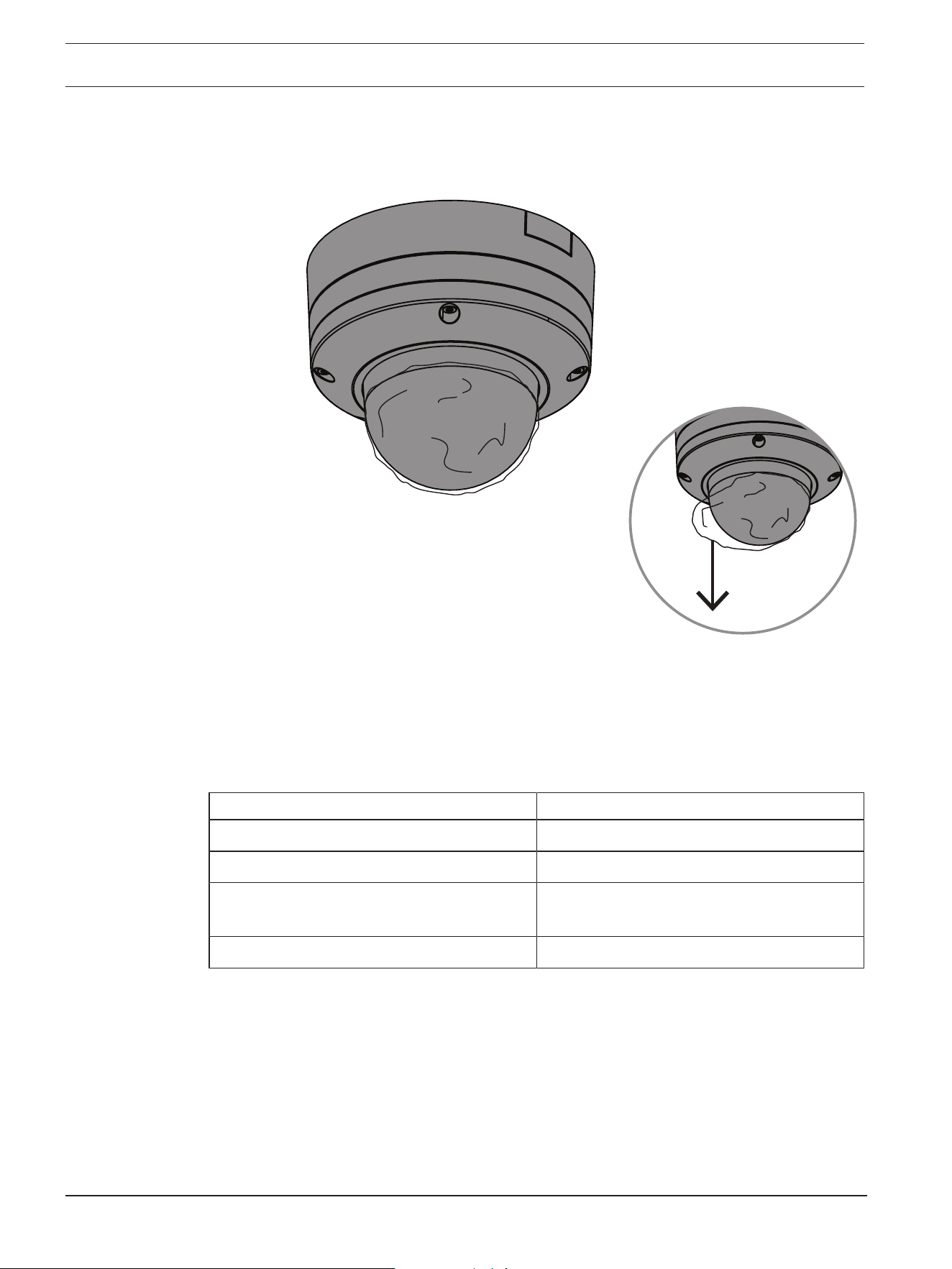
6.6 Removing the camera
1. Untighten the 4 captive screws of the screw holes in the camera module.
2. Push the camera upwards and rotate counterclockwise to un-click it from the mounting
plate.
3. Disconnect the Ethernet cable and remove the camera.
42 en | Commissioning FLEXIDOME 8100i | FLEXIDOME 8100i — X series
2024-11 | V01 | F.01U.411.088
Installation manual
Bosch Security Systems, BV
7 Commissioning
With the FLEXIDOME 8100i and FLEXIDOME 8100i – X series remote commissioning
functionality, only a PC or a mobile device is needed to pan, tilt, roll, and zoom (PTRZ), and
point the camera to the required field of view - without ever having to remove the camera
from the box.
Do the commissioning locally at the camera via wireless access to local network using the
Project Assistant app, available for iOS, Windows or Android, or by connecting remotely to
the camera via the network using the Project Assistant app, the camera’s web interface, or
the Configuration Manager.
To commission the camera using the Project Assistant app:
1. Connect the network cable to the PoE.
2. Download the Project Assistant app.
3. Do the necessary steps to configure the device. Use the step-by-step instructional video
for help.
If required, re-commissioning can be done at any time.
i
Notice!
The remote commissioning functionality (PTRZ) of the camera is designed as installation
aid for first set-up or adjustments at a later moment in time.

FLEXIDOME 8100i | FLEXIDOME 8100i — X series Connection via the web browser | en 43
Bosch Security Systems, BV
Installation manual
2024-11 | V01 | F.01U.411.088
8 Connection via the web browser
A computer with a web browser (Google Chrome, Microsoft Edge, or Mozilla Firefox) is used
to receive live images, control the unit, and replay stored sequences. The unit is configured
over the network using the browser.
8.1 System requirements
Our recommendations are:
– Computer with Dual core HyperThreading processor or better
– Graphic card with performance that matches or is better than the resolution of the
camera
– Windows10 or later
– Network access
– Google Chrome, Microsoft Edge, or Mozilla Firefox
- or -
Application software, for example, VideoSecurityClient or BVMS.
8.2 Establishing the connection
The unit must have a valid IP address and a compatible subnet mask to operate on your
network. By default, DHCP is pre-set at the factory to On and so your DHCP server assigns
an IP address. With no DHCP server the default address is automatically assigned via link-
local address.
The Project Assistant app or Configuration Manager (version 7.74 or higher) can be used to
find the IP address. Download the software from https://downloadstore.boschsecurity.com
:
1. Start the web browser.
2. Enter the IP address of the device as the URL.
3. During the initial installation, confirm any security questions that show.
Note:
If you cannot connect, the unit may have reached its maximum number of connections.
Depending on the device and network configuration, each unit can have up to 50 web
browser connections, or up to 100 connections via BVMS.
8.3 Password protection in camera
The camera requires a strong password. Follow the prompts in the dialog box, which
specifies what is required. The system measures the strength of the password that you
enter.
When you use Configuration Manager to access your device for the first time, you must set
the initial password of the device in Configuration Manager. The Users section (General >
Unit Access > Users) displays the message, "Before you can use this device you have to
secure it with an initial password."
Note: After you set the initial password, a "lock" icon appears next to the device name in the
Devices list in Configuration Manager.
You can also launch the device webpage directly. In the device webpage, an initial password
page appears, displaying input fields and a password strength gauge.
Enter the user name (“service”) and a password in the appropriate fields. Refer to the
section User Management for more information.

44 en | Connection via the web browser FLEXIDOME 8100i | FLEXIDOME 8100i — X series
2024-11 | V01 | F.01U.411.088
Installation manual
Bosch Security Systems, BV
After a service-level password is set for the device, the device displays a dialog box that
prompts users to enter the user name (“service”) and the service-level password every time
that they access the device.
1. Fill in the fields User name and Password.
2. Click OK. If the password is correct, the desired page appears.
Note: New releases of software may require you to set a new and stronger password.
FLEXIDOME 8100i | FLEXIDOME 8100i — X series Troubleshooting | en 45
Bosch Security Systems, BV
Installation manual
2024-11 | V01 | F.01U.411.088
9 Troubleshooting
9.1 Resolving problems
The following table is intended to help identify the causes of malfunctions and correct them
where possible.
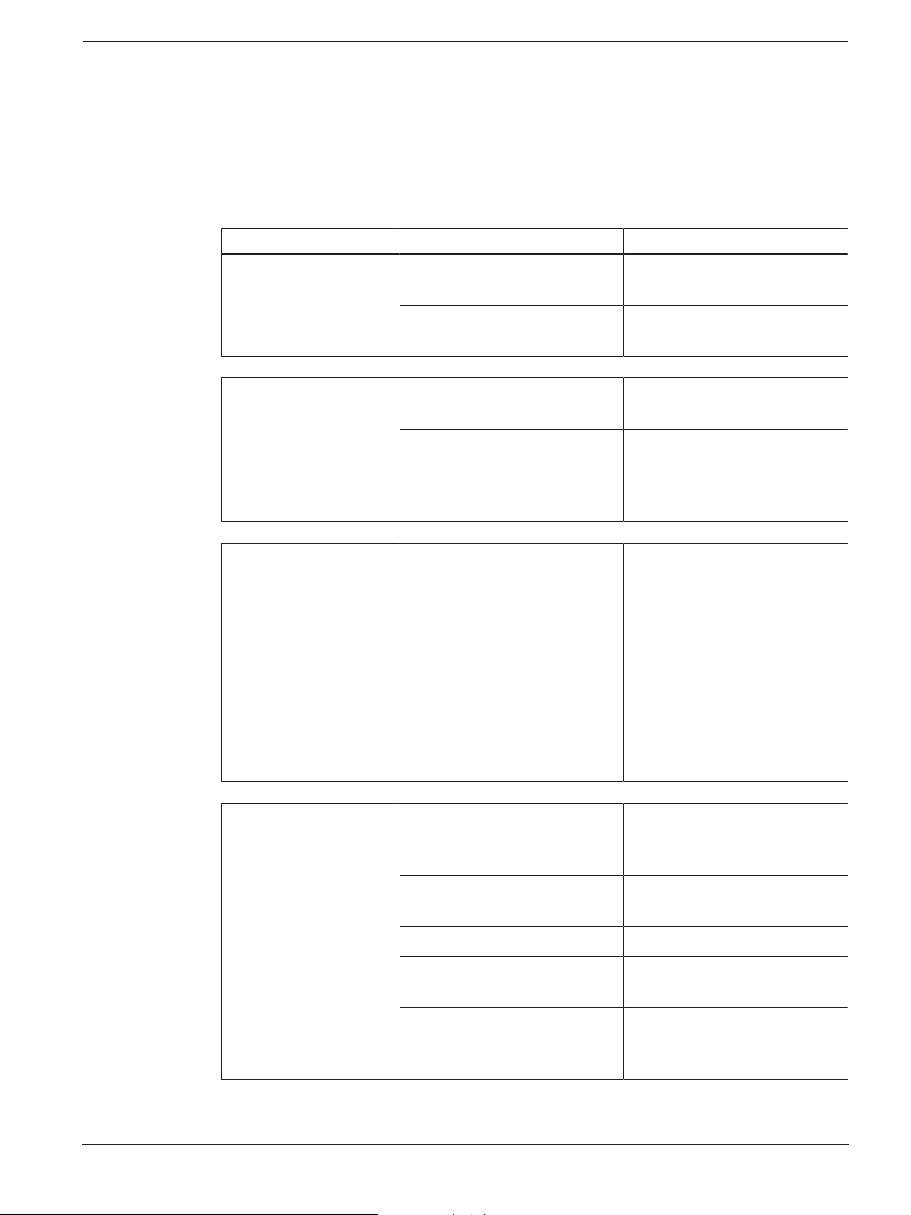
Malfunction Possible causes Solution
Unit does not operate. Power failure. Make sure that the power
supply is working properly.
Faulty cable connections. Do a check of all cables, plugs,
contacts, and connections.
PTRZ does not work Motors have been used for long
and have overheated.
Pause any lens movement until
motors have cooled down.
Camera parts are out of place
or broken due to
transportation.
Please contact your supplier or
system integrator, or go
directly to Bosch Security
Systems customer service.
PTRZ does not work
correctly.
Camera has lost calibration
during transportation.
Reset the PTR in the user
interface to reset the pan, tilt
and roll motors.
Reset the lens in the user
interface to reset the focus and
zoom of the lens.
If that does not work, please
contact your supplier or system
integrator, or go directly to
Bosch Security Systems
customer service.
No connection
established, no image
transmission.
Incorrect unit configuration. Check all configuration
parameters (reset to factory
default if necessary).
Faulty installation. Check all cables, plugs,
contacts and connections.
Wrong IP address. Check the IP addresses (ping).
Faulty data transmission within
the LAN.
Check the data transmission
with ping.
The maximum number of
connections has been reached.
Wait until there is a free
connection and call the
transmitter again.

46 en | Troubleshooting FLEXIDOME 8100i | FLEXIDOME 8100i — X series
2024-11 | V01 | F.01U.411.088
Installation manual
Bosch Security Systems, BV
Moisture/condensation
inside the bubble,
camera leaking.
Housing is not closed properly. Re-install camera and check for
proper closure of bubble cover
and SD card lid.
Closing seals are damaged. Please contact your supplier or
system integrator, or go
directly to Bosch Security
Systems customer service.
Rubber grommet not placed
correctly on IP54 protection
kit..
Re-install rubber grommet.
Cable diameter or shape is not
as specified for IP54 protection
kit.
Re-install camera with proper
cabling.
Air vent is blocked due to dirt/
water.
Gently clean air vent..
Air vents are damaged or loose. Please contact your supplier or
system integrator, or go
directly to Bosch Security
Systems customer service.
Camera has been off for an
extensive period of time.
Turn camera on and leave it on
until condensation clears.
No audio transmission to
remote station
Faulty microphone cable
connection.
Open camera bubble and
correctly connect microphone
connector.
Incorrect configuration. Check audio parameters on the
Audio configuration and LIVE
page functions pages.
The unit does not report
an alarm.
Alarm source is not selected. Select possible alarm sources
on the Alarm sources
configuration page.
No alarm response specified. Specify the desired alarm
response on the Alarm
connections configuration
page; if necessary change the
IP address.
The unit is not
operational after a
firmware upload.
Power failure during
programming by firmware file.
Have the unit checked by
Customer Service and replace
if necessary.

FLEXIDOME 8100i | FLEXIDOME 8100i — X series Troubleshooting | en 47
Bosch Security Systems, BV
Installation manual
2024-11 | V01 | F.01U.411.088
Incorrect firmware file. Enter the IP address of the unit
followed by /main.htm in your
Web browser and repeat the
upload.
Web browser contains
empty fields.
Active proxy server in network. Create a rule in the local
computer's proxy settings to
exclude local IP addresses.
9.2 Testing the network connection
The ping command can be used to check the connection between two IP addresses. This
allows testing whether a device is active in the network.
1. Open the DOS command prompt.
2. Type ping followed by the IP address of the device.
If the device is found, the response appears as "Reply from ... ", followed by the number of
bytes sent and the transmission time in milliseconds. Otherwise, the device cannot be
accessed via the network. This might be because:
– The device is not properly connected to the network. Check the cable connections in
this case.
– The device is not correctly integrated into the network. Check the IP address, subnet
mask, and gateway address.
9.3 Customer service
If a fault cannot be resolved, please contact your supplier or system integrator, or go
directly to Bosch Security Systems customer service.
The version numbers of the internal firmware can be viewed on a service page. Please note
this information before contacting customer service.
1. In the address bar of your browser, after the unit IP address, enter: /version
for example: 192.168.0.80/version
2. Write down the information or print out the page.
48 en | Maintenance FLEXIDOME 8100i | FLEXIDOME 8100i — X series
2024-11 | V01 | F.01U.411.088
Installation manual
Bosch Security Systems, BV
10 Maintenance
There are different types of bubbles available to choose from. All bubbles require special
care when handling and cleaning to avoid scratches.
10.1 Bubble handling
The bubble may be packaged with a protective plastic sheet. It is recommended that the
bubble remain stored this way until it is ready to install. Limit handling the bubble, as any
scratches can quickly affect visibility.
10.2 Bubble cleaning
If cleaning the bubble is required, use the following procedures and comply with all the
warnings listed below.
Cleaning the bubble interior
The extremely soft interior surface should not be cleaned by rubbing or dusting with a cloth.
Use clean dry compressed air, preferably from a spray can, to remove any dust from the
interior surface.
!
Warning!
Do not use alcohol-based solutions to clean the bubble. This will cause it to cloud and over
time cause stress aging, which makes the bubble brittle.
Cleaning the bubble exterior
The exterior of the bubble is hard coated for increased scratch resistance. If cleaning is
needed, only use clean microfiber lens cloths use a non-abrasive, solvent-free neutral soap
or detergent with water. Dry the bubble thoroughly with a dry and clean microfiber lens
cloth to prevent water spots. Never scrub the bubble with any abrasive material or cleaners.
Cautions
– Do not clean bubbles in the hot sun or on very hot days.
– Do not use abrasive or highly alkaline cleaners on the bubble.
– Do not scrape the bubble with razor blades or other sharp instruments.
– Do not use Benzene, Gasoline, Acetone, or Carbon Tetrachloride on the bubble.
10.3 Bubble replacement
i
Notice!
Yellowing of bubble
Bubble may become yellow overtime due to exposure to UV radiation like direct or indirect
sunlight.
In case the bubble gets damaged or yellow, it can be replaced by a clear bubble (NDA-8000-
CBL), a tinted bubble (NDA-8000-TBL), or a hydrophilic bubble (NDA-8000-HCBL).

FLEXIDOME 8100i | FLEXIDOME 8100i — X series Maintenance | en 49
Bosch Security Systems, BV
Installation manual
2024-11 | V01 | F.01U.411.088
Clear bubbles offer maximum sensitivity by allowing as much light through as possible.
Tinted bubbles offer covertness by making it difficult to see from the outside the direction
the camera is facing. Hydrophilic bubbles help shield the dome from water droplets in rainy
conditions.
For instructions on how to replace the bubble, refer to the respective Quick Installation
Guide.
10.4 Camera reset
To reset the camera to factory settings:
1. Remove the camera module from the camera base.
2. Press tightly and hold the reset button on top of the micro SD card slot until the LED
light by the reset button flashes in red.
3. Release the reset button.
– If LED light does not flash, connect the camera to a network cable with PoE+ and
repeat steps 2 and 3.
4. Re-attach the camera module onto the camera base.
50 en | Decommissioning FLEXIDOME 8100i | FLEXIDOME 8100i — X series
2024-11 | V01 | F.01U.411.088
Installation manual
Bosch Security Systems, BV
11 Decommissioning
11.1 Transfer
The device should only be passed on together with this Installation manual.
11.2 Disposal
Old electrical and electronic equipment
This product and/or battery must be disposed of separately from household waste.
Dispose such equipment according to local laws and regulations, to allow their
reuse and/or recycling. This will help in conserving resources, and in protecting
human health and the environment.
Support
Access our support services at www.boschsecurity.com/xc/en/support/
.
Bosch Security and Safety Systems offers support in these areas:
– Apps & Tools
– Building Information Modeling
– Warranty
– Troubleshooting
– Repair & Exchange
– Product Security
Bosch Building Technologies Academy
Visit the Bosch Building Technologies Academy website and have access to training courses,
video tutorials and documents: www.boschsecurity.com/xc/en/support/training/


Bosch Security Systems B.V.
Torenallee 49
5617 BA Eindhoven
Netherlands
www.boschsecurity.com
© Bosch Security Systems B.V., 2024
202411271553
Building solutions for a better life