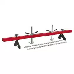
ENGINE SUPPORT BEAM
500kG cAPAcITy, dOUBlE SUPPORT
Model no: ES502.V2
Thank you for purchasing a Sealey product. Manufactured to a high standard, this product will, if used according to these
instructions, and properly maintained, give you years of trouble free performance.
IMPORTANT: PLEASE READ THESE INSTRUCTIONS CAREFULLY. NOTE THE SAFE OPERATIONAL REQUIREMENTS, WARNINGS & CAUTIONS. USE
THE PRODUCT CORRECTLY AND WITH CARE FOR THE PURPOSE FOR WHICH IT IS INTENDED. FAILURE TO DO SO MAY CAUSE DAMAGE AND/OR
PERSONAL INJURY AND WILL INVALIDATE THE WARRANTY. KEEP THESE INSTRUCTIONS SAFE FOR FUTURE USE.
1. SAfETy
9 ensure that the engine support is in good working order. Take action for immediate repair or replacement of damaged parts. Use
genuine parts only. The use of unauthorised parts may be dangerous and will invalidate the warranty.
9 locate the vehicle in a suitable, well lit work area.
9 Keep work area clean and tidy and free from unrelated materials.
9 ensure the vehicle handbrake is engaged and the engine/motor is switched off.
9 ensure all non-essential persons keep a safe distance whilst the engine support is in use.
8 dO NOT use the engine support if damaged.
8 dO NOT allow untrained persons to operate the engine support.
8 dO NOT use the engine support for purposes other than that for which it is designed.
8 dO NOT exceed the rated capacity of the engine support.
9 When not in use, store engine support in a safe, dry, childproof area.
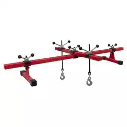
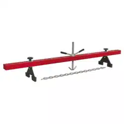
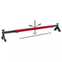
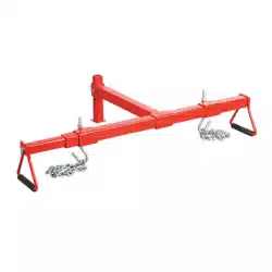
2. INTROdUcTION
designed to support and accurately position engines during maintenance operations such as replacing anti-vibration mountings and
certain body panels. Also used as an aid for the removal of gearboxes and transmissions. Beam is supported on rubber feet and fine
adjustment control is obtained by using two screw/hook mechanisms. Supplied with two short lengths of chain.
3. SPEcIfIcATION
Maximum Capacity .......................................................... 500kg
Maximum Width ...........................................................1580mm
Minimum Width ..............................................................585mm
Screw Travel ..................................................................230mm
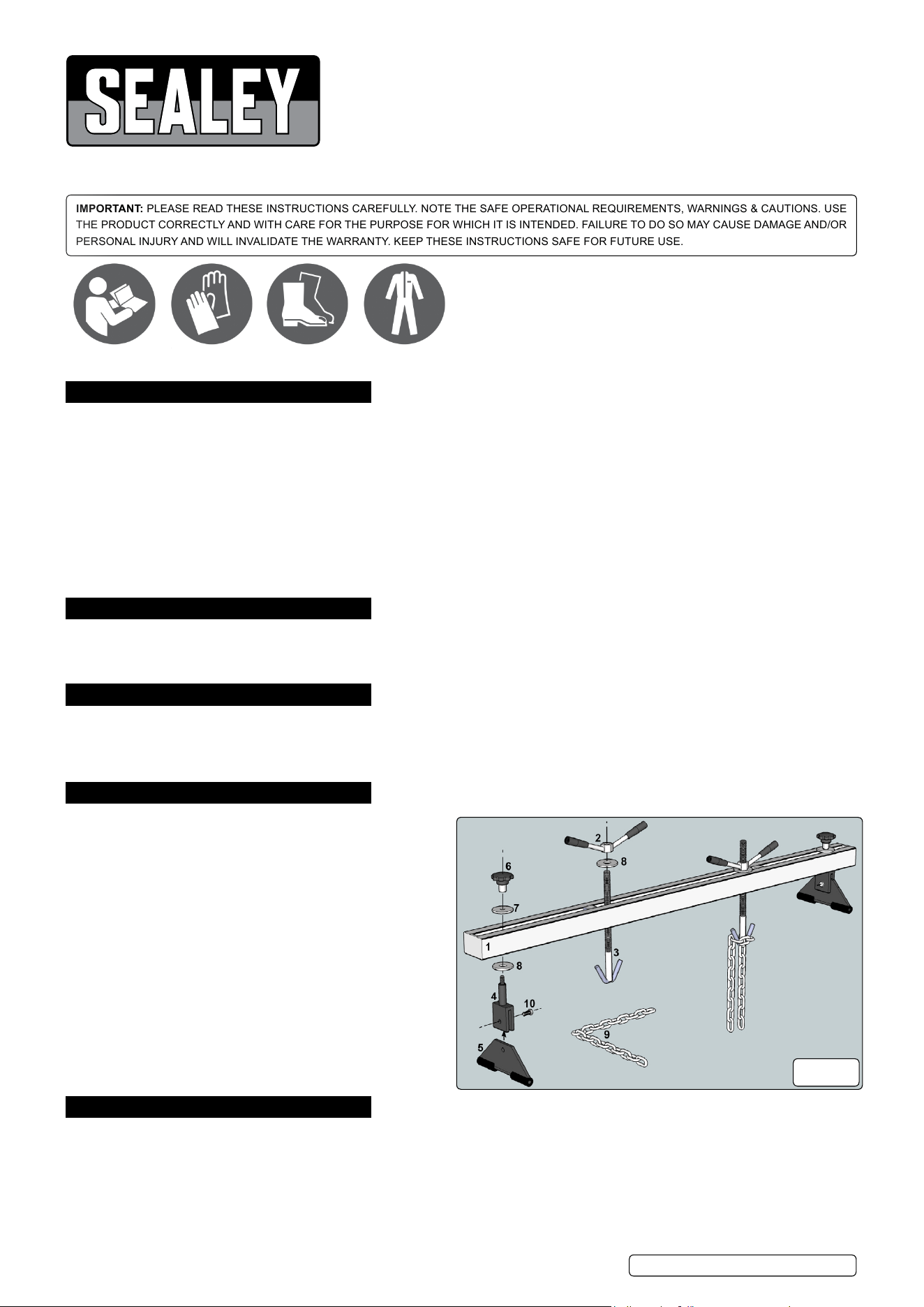
4. cONTENTS
4.1. Refertog.1.
Item ........................................................... description
1............................................................................Beam
2............................................................... lifting Handle
3..........................................................Adjustable Screw
4............................................................. Standing Block
5..............................................................................Foot
6.....................................................................Grip Knob
7............................................. Washer 13mm Internal Ø
8............................................. Washer 22mm Internal Ø
9............................................................................Chain
10..................................M10 x 30 Bolt 16mm & locknut
5. ASSEMBly
Note: numbers in brackets refer to item numbers shown in fig.1
5.1. Insert a foot (5) into the slot in the standing block (4). Align the holes in the two components and join them together using an M12 x 25
bolt (10). note that the standing block (4) has a threaded hole on one side and a clearance hole on the other.
5.2. Place a large washer (8) over the upstanding rod on the standing block (4) and insert the rod through the slot in the main support
guide from underneath. Place a large washer (7) over the thread on top of the rod and secure the assembly to the main support guide
by screwing on a grip knob (6) as shown in fig.1. Assemble the other foot/standing block and fix the assembly to the other end of the
main guide beam in the same way.
g.1
eS502.V2 Issue 2 (HF) 20/08/18
Original Language Version
© Jack Sealey limited
Refer to
instructions
Wear protective
gloves
Wear safety
footwear
Wear protective
clothing

5.3. drop a large washer (8) over an adjustable screw (3) and screw a lift handle (2) onto the top of the adjustable screw. Screw the lift
handle approximately half way down the threads. Make up the second adjustable screw in the same way and have both assemblies
ready to drop through the slot in the main guide beam after the beam has been placed over the engine bay.
5.4. The chains should also be attached when the guide beam is mounted over the engine.
6. OPERATION
Note: numbers in brackets refer to item numbers shown in fig.1
6.1. The fully assembled support beam is very heavy and should be lifted into place by two people.
6.2. loosen the grip knobs (6) to allow the assemblies to slide and then locate the rubber feet into the gutters of the vehicle’s front wing
panels or close to the suspension strut towers.
Note: Refer to the manufacturer’s handbook to identify engine lifting brackets.
6.3. drop the adjustable screw assemblies through the slot in the main beam in positions adjacent to the engine lifting points.
6.4. Attach the ends of the chain to the lifting brackets on the engine.
6.5. The chains may be attached to the lifting hooks in a single or looped chain configuration.
6.6. lower the adjustable screws and hook the chains around the hooks. In all cases ensure that at least one link of the chain is hooked
over the lifting hooks.
6.7. Tighten both grip knobs (6).
6.8. Progressively rotate the lifting handles (2) clockwise to tighten the chains and support the engine.
6.9. on completion of the maintenance task, rotate the lifting handles anticlockwise to release the tension on the chains.
6.10. Unhook the chains, loosen both grips (6) and remove the engine support from the vehicle.
6.11. Remove the chains from the engine lifting points.
Sealey Group, kempson Way, Suffolk Business Park, Bury St Edmunds, Suffolk. IP32 7AR
01284 757500 01284 703534 sales@sealey.co.uk www.sealey.co.uk
ENVIRONMENT PROTEcTION
Recycle unwanted materials instead of disposing of them as waste. All tools, accessories and packaging should be sorted, taken to
a recycling centre and disposed of in a manner which is compatible with the environment. When the product becomes completely
unserviceable and requires disposal, drain any fluids (if applicable) into approved containers and dispose of the product and fluids
according to local regulations.
Note: It is our policy to continually improve products and as such we reserve the right to alter data, specifications and component parts without prior
notice.
Important: no liability is accepted for incorrect use of this product.
Warranty: Guarantee is 12 months from purchase date, proof of which is required for any claim.
eS502.V2 Issue 2 (HF) 20/08/18
Original Language Version
© Jack Sealey limited