
INSTALLATION and
USE & CARE
WALL HOODS
Models starting with: AT, BZ, HA, IN, ME, MH, NR, PL, PM, PY, SC, WR
197299 Rev 1
Please take a few moments now to fill in the information below for your future reference in the event you
require parts or service.
DATE OF PURCHASE:
DEALER’S NAME:
DEALER’S ADDRESS:
DATE OF INSTALLATION:
INSTALLER’S NAME:
INSTALLER’S ADDRESS:
MODEL NUMBER:
SERIAL NUMBER:

Table of Contents
INSTALLATION INSTRUCTIONS:
5 Handling and Unpacking
7 Installation of Ducting & Electrical Specifications
8 Removing Liner from Hood Shell
9 Installing In-Hood Blowers
10 Installing Remote External Blowers
11 Installing Remote In-Line Blowers
12 Wiring Remote Blowers (HYEX or ATEX)
14 Mounting Hood Shell to Wall and Reinstalling Liner
15 Installing Duct Covers
16 Installing Models Starting with “MH”
USE AND CARE INSTRUCTIONS:
17 Operating the Push Button Controls
18 Cleaning Instructions

1. This appliance was designed for ease of installation and operation. However, we recommend that you read all
sections of this manual before you begin installation.
2. Do not remove permanently affixed labels, warnings or data plates from your appliance. This may void the
manufacturer’s warranty and/or hinder effective servicing and maintenance. These instructions are to remain with
the appliance and the consumer is to retain them for future reference.
3. Please observe all local and national build codes and ordinances. If no local codes are applicable, please follow all
wiring requirements in accordance with the National Electrical Code.
4. Please check your local codes for any make-up air requirements.
5. This hood is for residential use only and is not designed for installation over a commercial product.
IMPORTANT
To reduce the risk of fire, electric shock or injury observe the following:
• Use this unit in the manner intended by the manufacturer.
• Before cleaning or servicing unit, turn power off to the unit at the service panel.
• Installation work and electrical work must be performed by qualified individuals in accordance with all applicable
codes and standards, including fire-rated construction.
• Do not damage any existing electrical or hidden utilities when drilling, cutting and/or removing a wall, ceiling or floor.
• Sufficient air is required to properly exhaust gases through the flue of natural and liquid propane fueled cooking
equipment to avoid any backdrafts.
• Use only metal ductwork. Do not use flexible or corrugated duct.
• Never vent ducted exhaust air into another room or garage. Ducted exhaust air must vent outdoors.
WARNING
INSTALLATION INSTRUCTIONS
4

• If a fire should occur, do not turn on hood to evacuate smoke. Turn off hood.
• Do not use to exhaust hazardous, flammable or explosive materials.
• Clean baffle filters often, since accumulated grease can be a fire hazard and affect the performance of your
ventilation hood.
WARNING
Handling:
• Do not remove the hood from original packaging until you are ready to install.
• Remove all watches, belt buckles, jewelry, rings and any clothing with metal buttons or snaps to prevent damage to
the hood.
• When you begin the installation process, remove the hood from its original packaging and place on a clean, non-
abrasive blanket.
• When removing the hood from the carton, locate the filters since they could be packed separately.
INSTALLATION INSTRUCTIONS
5
Unpacking:
• Ensure the container is upright. If the container is not upright, major damage can occur to your appliance.
• Move the container as close to its installation location as possible. This will reduce moving and handling your
appliance once it is out of its shipping container.
INSTALLATION INSTRUCTIONS
To reduce the risk of fire and electric shock, install this ventilation unit only with manufacturer approved blowers. This
includes blowers rated maximum 8.4 amps – remote or combined integral blowers. Your ventilation hood is designed
to work specifically with the integral or remote blower requested.
CAUTION
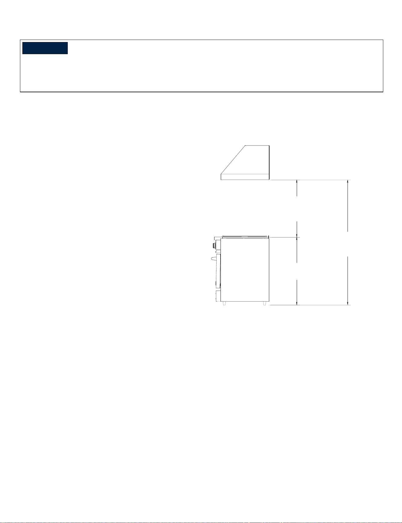
In selecting the proper height to mount the hood, take
into consideration the stature of the person or persons
who will be cooking. A minimum height of 30” off the
cooking surface to a maximum height of 36” will suit
most users. It is recommended, but not required, that
the hood be 6” wider than the cooking appliance to
provide a proper capture area for heat and grease.
The bottom of the hood should be 30” minimum to 36”
maximum above the countertop. This would typically
result in the bottom of the hood being 66” – 72” above
the floor. The bottom of the hood should never be more
than 72” above the floor or more than 36” above the
countertop. These dimensions provide safe and
efficient operation of the hood.
Site Preparation: Selecting the Appropriate Height for Installation
HEIGHT FROM FLOOR
68"(MIN)-72"(MAX)
167.6cm-182.9cm
COUNTERTOP
HEIGHT ABOVE COUNTERTOP
30"(MIN)-36"(MAX)
76.2CM-91.4CM
Height above Countertop
30” min – 36” max
762mm – 914mm
Height from Floor
66” min – 72” max
1676mm – 1829mm
Countertop
36” (914mm) typical
6
Installation of Ducting for Proper Operation:
Proper installation of ducting is extremely important for optimal performance of your ventilation system. It is a basic
requirement that the kitchen is provided with an air intake to ensure good air circulation and, therefore, proper operation
of the hood. Without this incoming air, a depression could form that would reduce the efficiency of the ventilation
system.
• Be sure to follow local building codes for electrical, structural, general HVAC, and make-up air requirements.
• If duct shape is changed along path (round to square), the cross-sectional area must not be reduced.
• The duct run should be kept under 30 feet for a straight run. For every 90 degree turn in the duct run, subtract 5 feet
from the total (25’ for a duct run with 1 elbow, 20’ for a duct run with 2 elbows, and so on). Longer runs will result in
decreased performance and possible noise concerns.
• Avoid sharp-angled turns. Use smooth gradual turns, such as adjustable elbows or 45-degree angled turns.
• Airflow must not be restricted at the end of the duct run.
• A backflow damper is not provided. It should be sourced locally and sized for your specific duct work.
• Duct should terminate to an outdoor space above the roof line or outside a side wall of the building. Do not
terminate the run into an attic or chimney.
INSTALLATION INSTRUCTIONS
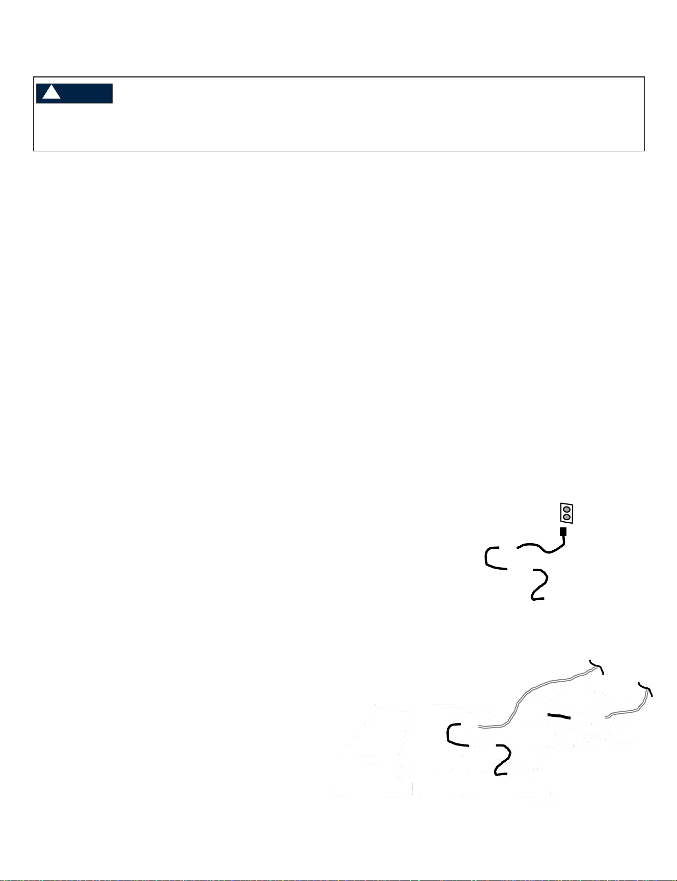
Electrical Specifications:
This hood is designed to be plugged into a dedicated 3-
prong ANSI or Non-GFCI outlet – 120Volt, 60Hz, 1Ph,
10amp. min.
Outlet location: Confirm with local building codes for
accessibility requirements. The outlet may be
positioned above the hood shell to provide access for
the cord along the duct exhaust. Ensure the outlet will
not be obstructed by the duct work. The power cord will
extend up to 36” from the top of the liner.
Depending on specific installation conditions,
access to the outlet may be difficult.
If an appropriate outlet is not available or is inconvenient
due to the specific installation, the power cord may be
removed at the liner’s junction box, and the hood may
be direct wired to a dedicated non-GFCI 120V, 60Hz,
1Ph, 10amp min circuit. Use 14-2 MC shielded cable or
equivalent, unless directed otherwise by local building
codes.
7
3-prong cord attached
3-prong cord removed
for direct wire
To reduce the risk of fire, electric shock or injury, observe the following:
• Use only metal ductwork. Do not use flexible or corrugated duct.
WARNING
INSTALLATION INSTRUCTIONS
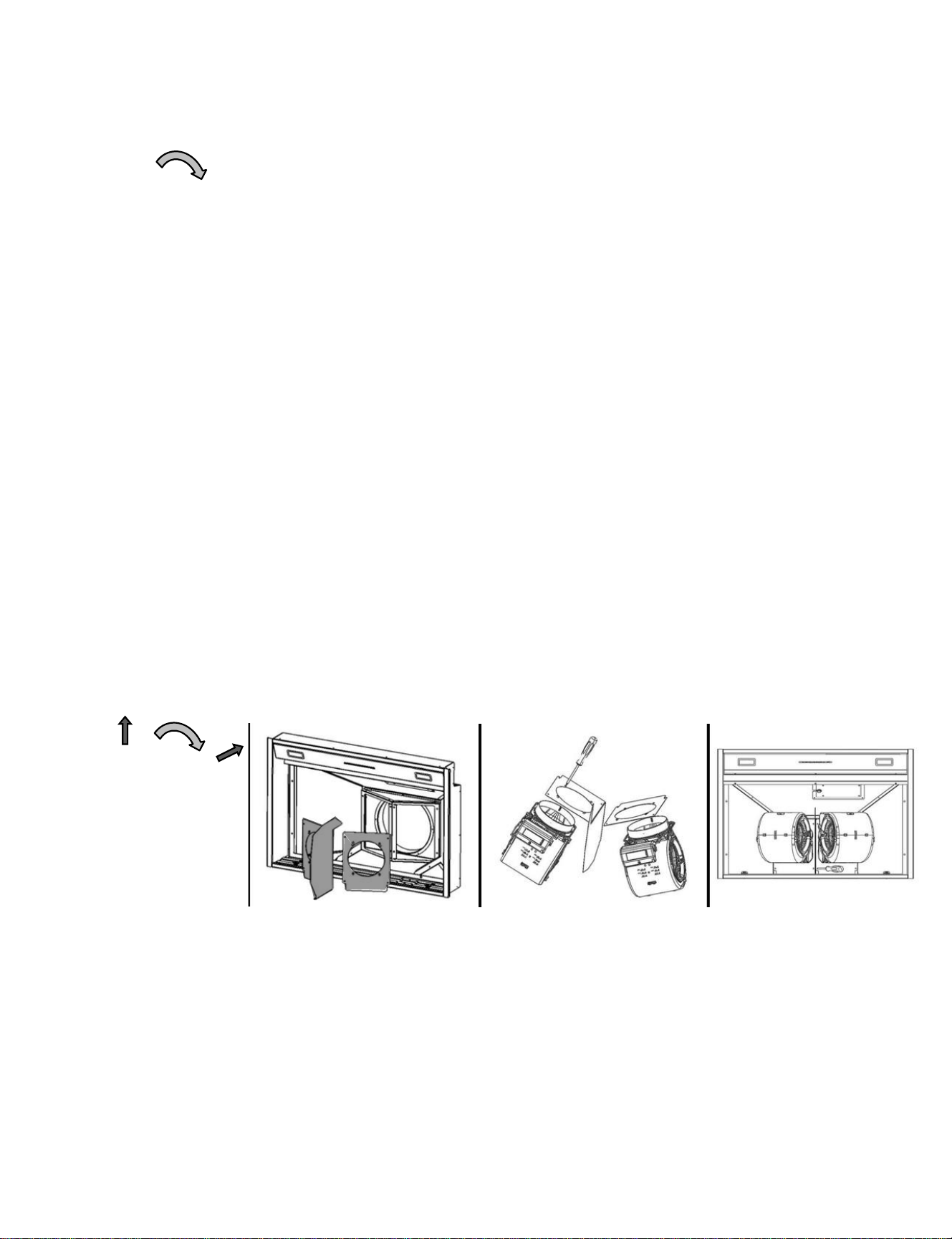
Figure E: Remove
Mounting Screws
Remove Philips screws in
front and back of liner that
attach it to the outer shell.
Screws are located behind
scalloped detail in trough
front and back.
E. F.
Step 3: Set liner aside and prepare for blower installation.
1. If a duct cover is being used review pages 13-15 to determine which installation process will work best for your
application. If no duct cover is being used proceed to Step 4.
2. If installing an in-hood blower kit, proceed with Steps 4-1 (600 cfm single), or Step 4-2 (1200 cfm double).
3. If installing a remote blower kit, prepare the liner as follows:
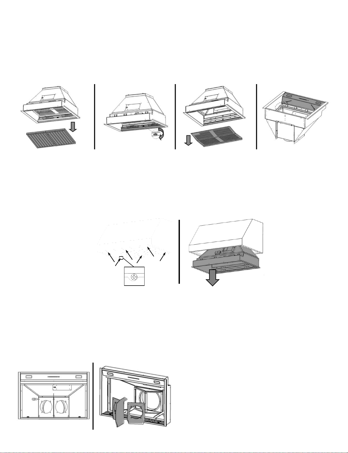
Step 2: Remove ventilation hood liner from outer shell. (Figures A through F) – save all components and fasteners as
they will be used to reinstall the liner after the hood shell is mounted to the wall.
Figure A:
Remove Baffle Filters
Pull filter(s) towards front
of hood and tilt rear of
filter down to remove.
Figure B:
Remove Grease Trough
Turn wing fastener(s) ¼
turn to unlock.
Figure C:
Remove Inner Shield
Remove Philips screws (front
and back) attaching shield to
ventilation hood liner.
(Inner shield not on all models)
Figure D:
Remove Control Panel
Remove screws attaching
panel to ventilation hood
liner. Disconnect control
and light harnesses.
A. B. C. D.
8
Confirm discharge direction is correct for application.
If not, remove top/rear plate assembly and rotate as
needed. Reinstall fasteners. If in-hood blower
mounting plates are present, they should be removed
and discarded.
Step 1: Read all instructions thoroughly before beginning installation. If a duct cover is being used, please review
all steps before beginning – for some installations, the order of assembly may be altered. Details which are unique to
models starting with “MH” are shown on page 16.
Figure F: Remove
Liner from Shell
Carefully slide liner out
of outer shell.
Remove any protective
film from exterior of liner
and baffle filters.
Step 4-1: Installing an In-hood 600 CFM Blower. Duct connection detail: 6” round
Recommended duct size: 6” – 8”
Figure A:
Set Discharge Direction,
Attach Blower
Unscrew blower plate and
set to top or rear discharge if
not already set correctly.
Screw blower to plate with
included hardware
Figure B:
Connect Plate Internally
Re-install all mounting
screws inside of liner.
Figure C:
Connect Plate Externally
Re-install all mounting
screws outside of liner.
Figure D:
Connect Power Supply
Plug 6-pin connector from
one of the control harnesses
to blower. Unused harness
may be tied securely to
other harness to prevent
vibration
Step 4-2: Installing an In-hood 1200 CFM Blower kit. Duct connection detail: 10” round
Required duct size: 10”
INSTALLATION INSTRUCTIONS
Figure A:
Set Discharge Direction.
If not already set correctly,
remove fasteners for top/rear
bracket and rotate to set to
top or rear discharge.
Reinstall all fasteners.
Figure B:
Remove Inner Plates
Remove all screws
securing blower mounting
plates and pull plates from
liner.
Figure C:
Connect Blowers
Install dual 600 CFM
blowers onto mounting
plates with included
hardware.
Figure D:
Install Blowers in Hood
and Connect to Power.
Reinstall blowers and
mounting plates to liner.
Plug 6-pin connectors from
control harness to each
blower.
9
INSTALLATION INSTRUCTIONS
Step 4-3. Installing an Exterior Roof or Wall Mounted Remote Blower (HYEX)
10
Model Number: HYEX-1.0 / HY-EX-1.4
Maximum rated CFM: 1000 CFM / 1400 CFM
Volts/Hz/Amps: 115VAC, 60 Hz, 2.9A (HYEX-1.0) / 3.3A (HYEX-1.4)
Required duct size: HYEX-1.0: 8” Round (51 sq. in. equiv.) / HYEX-1.4: 10” Round (80 sq. in. equiv.)
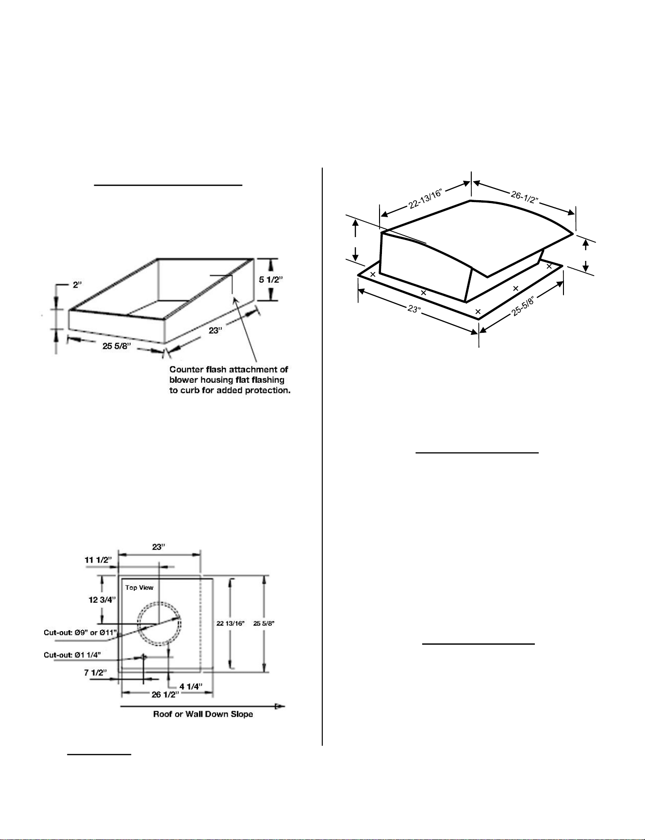
FLAT OR LOW SLOPE ROOF
1. For flat roofs or roofs having pitch less than 1 ½” rise
in 12”, mount blower on roof curb. See Figure 1
2. Install the blower with discharge pointing down slope
and away from prevailing winds.
3. Use flashing and roofing mastic to seal the unit to
prevent leaks.
4. Cut holes for ducting and electrical wiring as shown
in Figure 2.
Figure 1
Figure 2
IMPORTANT: Remove foam block(s) from
inside housing before operating
TYPICAL ROOF MOUNT
1. Center the duct cutout between roof rafters
2. Install the blower so its discharge is down slope and
away from prevailing winds. According to the
standard roofing procedures, shingles must cover
rear flashing flange and a minimum of 12” of the
side flanges. The flashing on the discharge side of
the blower must rest on top of the shingles.
3. The blower must be sealed between the roof and its
underside with quality roofing mastic.
Figure 3
DUCT CONNECTIONS
1. Use only round metal duct, elbows and transitions;
or rectangular ducting having equivalent cross-
sectional area per required duct size.
2. Tape or use joint sealant on all joints.
3. Make sure damper opens and closes freely.
For electrical connection, see Step 4-5. Wiring Remote Blowers (HYEX or ATEX)
7”
9”
Blower
Housing
Cover
▪ (X) indicates area to drill
pilot holes for attachment
to roof or curb.
▪ Seal mount screw heads
with roofing mastic.
▪ Use grommeted stainless
steel sheet metal screws
for attachment.
Alternate Mounting Option
1. Use temporary fixtures you can later remove to
hang the equipment at its proper elevation.
(Vibration isolation mounts and associated
hardware not included.)
2. Fasten the hanger directly to the structure or
somewhere between the suspended unit. Do not
overtighten the neoprene element.
3. Turn the rod assembly nuts right one complete turn
on each hanger. Repeat this step until the
temporary hanging fixtures are loose and the
piping or equipment load is suspended completely
on the vibration hangers.
4. Remove the temporary hanger fixtures.
5. Do additional turns on the spring/top hanger rod
nut to level the piping or the equipment. Turn right
to raise or left to lower.
6. If equipping the blower with isolators (FC clamps),
attach the isolators.
Mounting the Blower
Note: Optional vibration mounts are not supplied with
blower. Duct silencer kit and associated clamps are sold
separately.
1. Install wood supports as needed to mount the blower
to the framing in the attic or crawl space. Blower can
be mounted between framing members or suspended
from them with custom mounting brackets.
2. Mount the blower using the attached brackets with
screws to the wood supports.
3. Optional: If equipping the blower with vibration mounts
(not included), attach the mounts to the wood supports.
Attach the blower to the vibration mounts. Do not over-
tighten the compressible element.
4. If equipping the blower with a duct silencer kit and
clamps, attach them to the blower.
INSTALLATION INSTRUCTIONS
Step 4-4. Installing an In-line Blower (ATEX)
IMPORTANT: The blower should be mounted in an accessible location for service such as an attic or
crawl space. Follow all applicable building codes when installing this unit.
Model Number: ATEX-0.8 / ATEX-1.2
Maximum rated CFM: 800 CFM / 1200 CFM
Volts/Hz/Amps: 115VAC, 60 Hz, 3.0A (ATEX-0.8) and 3.0A (ATEX-1.2)
Required duct size: ATEX-0.8: 8” Round (51 sq. in. equiv.) / ATEX-1.2: 10” Round (80 sq. in. equiv.)
For electrical connection, see Step 4-5. Wiring Remote Blowers (HYEX or ATEX)
11
Use protective clothing such as cut resistant or mesh
gloves when working with sharp edges.
CAUTION
Model A C D E Weight
ATEX-0.8 8 12 ½ 15 ½ 7 19 lbs.
ATEX-1.2 10 14 15 8 21 lbs.
INSTALLATION INSTRUCTIONS
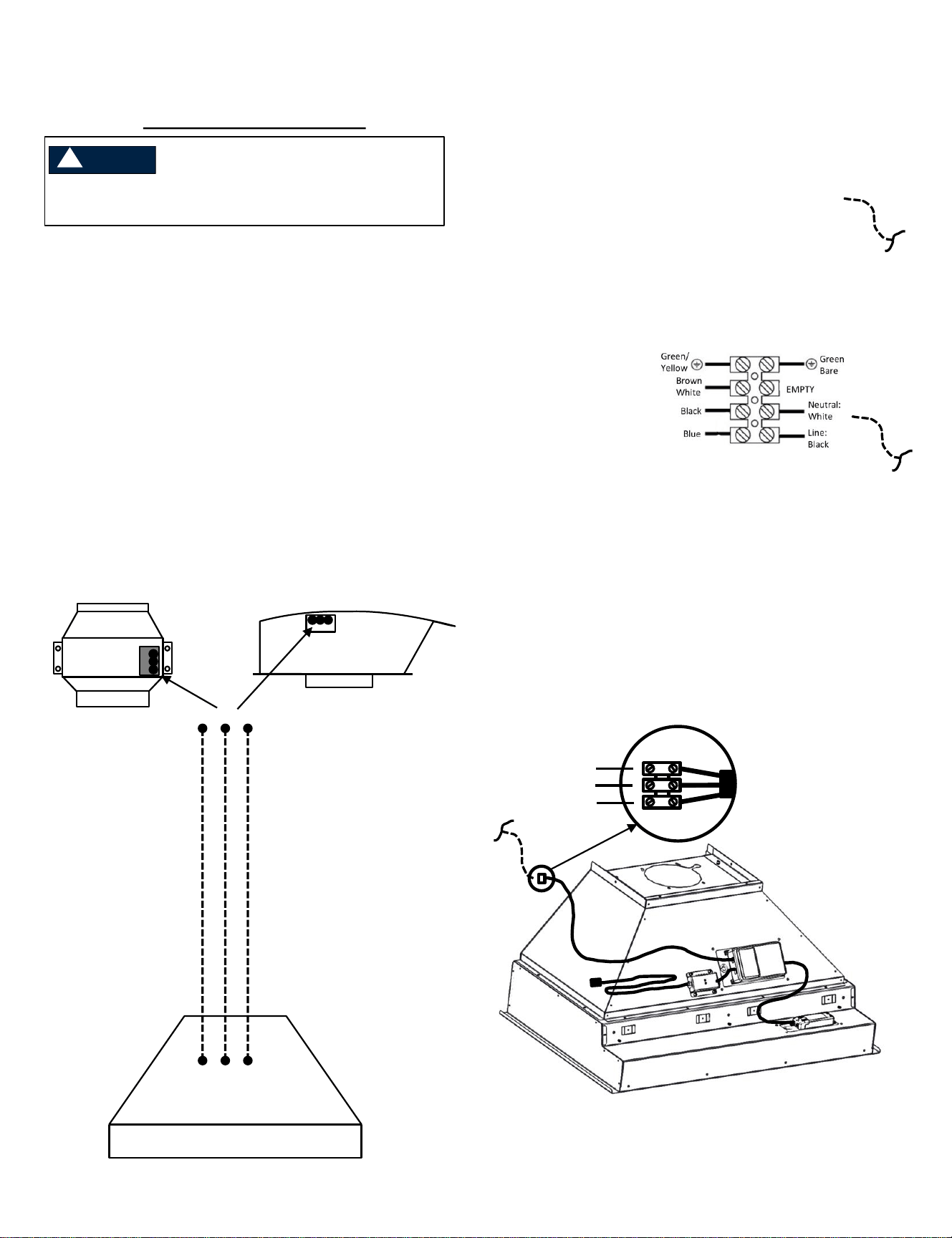
Step 4-5. Wiring Remote Blowers (HYEX or ATEX)
ELECTRICAL CONNECTIONS
1. Run a 3-conductor electrical cable between the
blower and the range hood. Local building codes
take precedence, but unless otherwise directed,
use 14-2 MC shielded cable or equivalent. See
Figure 4.
2. Connect cable to terminal block on blower at
proper locations. For ATEX blowers, use Figure 5.
For HYEX blowers, use Figure 6.
3. Connect electrical cable from blower to the three-
position terminal block on the hood’s wire harness.
See Figure 7. [NOTE: Depending on your site-
specific installation, this step may need to be done
later in the overall installation process to allow for
proper wire routing through the hood shell.]
Figure 4 Cable between Hood and Remote Blower
LINE/Black
NEUTRAL/White
GROUND/Green-Yellow or Bare
Range Hood
Connect remote
blower to hood
harness via a
3-conductor cable.
ATEX
Blower
HYEX Blower
OR
Figure 5 ATEX Blower Connection
Figure 6 HYEX Blower Connection
Figure 7 Connection to control cable in hood
Out to Blower:
LINE/Black
GROUND/Green/Yellow/Bare
NEUTRAL/White
From hood harness:
LINE/Brown (or Black)
GROUND/Green/Yellow/Bare
NEUTRAL/Red (or White)
Cable in
from hood
Motor
Leads
Motor
Leads
Cable in
from hood
12
Turn off power at the service panel prior to wiring the
blower.
WARNING
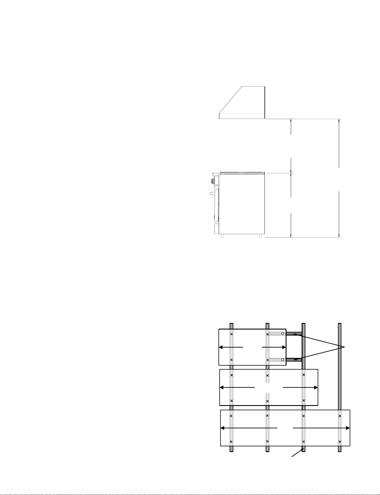
5. Hardware is not provided with this unit to secure it to the wall. Local building codes take precedence (where
applicable). Otherwise, use #12 screws or larger lag screws with a length such that at least 1” of thread is embedded
into a structural member (i.e., wood stud or blocking) behind the mounting surface. Be sure to consider the
thickness of wallboard (drywall, tile, etc.) when determining appropriate length of fastener. A minimum of 2 screws
in the upper portion of the hood, and 2 screws in the lower portion of the hood should be used to ensure the hood is
attached securely to the wall.
a. Additional screws should be used for wider hoods:
• 36” wide hoods and smaller:
2 screws upper portion, 2 screws lower portion.
• Greater than 36”, up to 54”:
3 screws upper portion, 3 screws lower portion.
• Greater than 54” wide:
4 screws upper portion, 4 screws lower portion.
INSTALLATION INSTRUCTIONS
1. The bottom of the hood should be 30” minimum to 36”
maximum above the countertop for efficient operation. The
hood should be centered over the cooking surface.
2. Measure and mark carefully and locate framing behind the
wallboard using a stud finder. Add structural blocking
where necessary to ensure hood is attached to the wall
securely.
3. In the back of some model’s hood shell, there are only a
few small oblong slots provided for screws to pass through.
If necessary, it is acceptable to drill new holes in the sheet
metal back of the hood shell to align with framing behind
wallboard.
4. Depending on fastener selected, pre-drilling may be
necessary to avoid splitting the framing or blocking.
HEIGHT FROM FLOOR
68"(MIN)-72"(MAX)
167.6cm-182.9cm
COUNTERTOP
HEIGHT ABOVE COUNTERTOP
30"(MIN)-36"(MAX)
76.2CM-91.4CM
Height above Countertop
30” min – 36” max
762mm – 914mm
Height from Floor
66” min – 72” max
1676mm – 1829mm
Countertop
36” (914mm) typical
>36”-54”
>54”
Step 5. Mount the Outer Hood Shell to the Wall
NOTE: If duct cover is being used, please review next steps carefully. Depending on your specific installation,
the duct cover may need to be installed prior to mounting the hood shell to the wall
13
<=36”
structural members / studs
optional
blocking
INSTALLATION INSTRUCTIONS
Step 7. Connect Ducting to Ventilation Hood
Install ducting around starter collar on top or rear of hood and seal according to building code regulations. Be sure to
include a back draft damper in the duct work to prevent drafts.
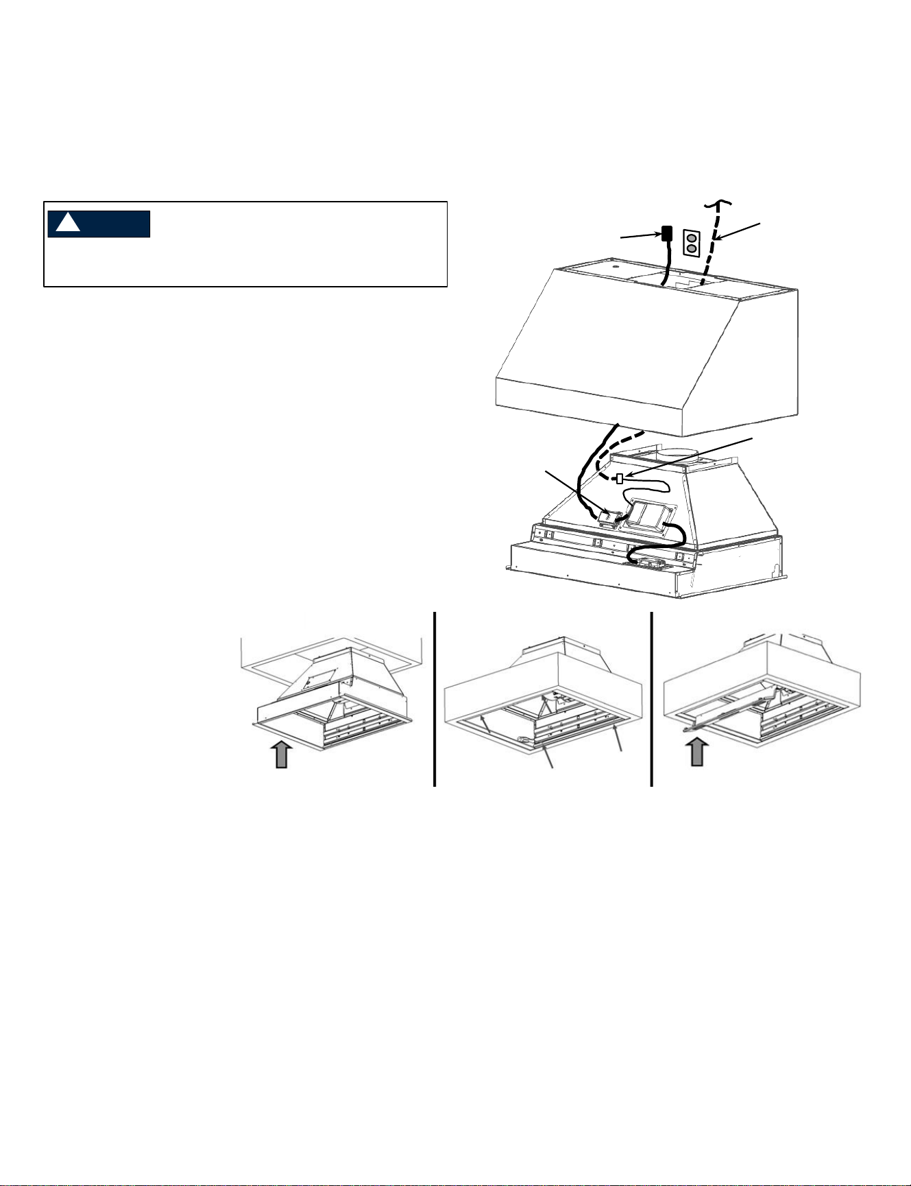
Step 6. Re-install Liner into Outer Shell
NOTE: If duct cover is being used, please review next steps carefully. Depending on your specific
installation, the duct cover may need to be installed prior to reinstalling the liner.
Figure A:
Lift Liner into Shell
Carefully re-install liner to
avoid scratches or damage.
Ensure cables are dressed
carefully to avoid pinching.
Figure B:
Attach Liner to Shell
Re-install with all the screws
removed previously that held
the liner to the hood shell
during shipment.
Figure C:
Re-install Control Panel,
Screen and Filters
Attach button control harness
and light wires. Insert control
panel’s tabs into slots in front of
liner. Drive screws attaching
panel to liner.
Install screen and filters.
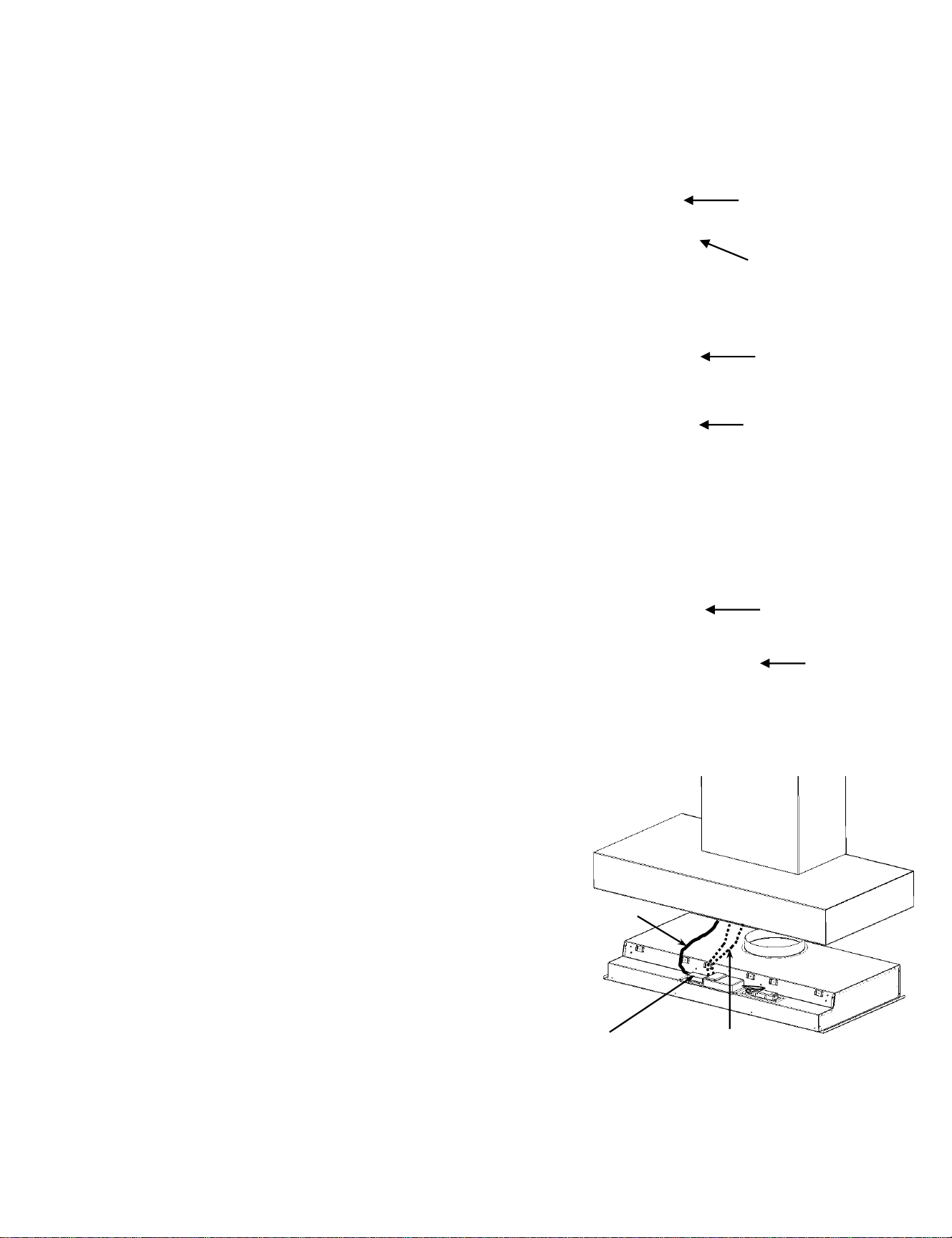
1. Connect Electrical Supply (see Electrical Specifications
on page 7)
a. Route power cord from liner to outlet location and
plug in.
b. If alternate direct wire method is desired, remove
power cord from junction box and connect power
supply cable directly in its place being sure to
match wire colors appropriately.
c. If remote blower is being used, route cable from
remote blower through top of hood shell and
connect to liner as directed in Step 4-5.
2. Complete liner
installation by inserting
into hood shell (A),
driving screws (B), and
reinstalling covers and
filters removed
previously (C).
3. If ductwork is already in
position, be sure to align
properly as liner is
inserted.
14
c. remote blower
power supply
(n/a for in-hood
blowers)
a. to outlet
b. power cord
junction box
c. remote blower
connection only
Turn off power at the service panel prior to wiring the
blower.
WARNING
INSTALLATION INSTRUCTIONS: DUCT COVERS
Installing a Telescopic Duct Cover
1. Attach upper mounting bracket to wall against ceiling and
centered with hood.
2. Attach lower mounting bracket to wall against top of hood shell.
3. Slide upper duct cover down into lower duct cover.
4. Place duct cover assembly on top of hood shell and raise the
upper portion so it is flush with ceiling. Drive screws into upper
mounting bracket to secure upper duct cover in position.
5. Drive remaining 2 screws into lower duct cover’s bracket.
(Duct cover should sit flush to ceiling, but gap could occur if wall and ceiling
are not square)
Upper Duct
Lower Duct
Upper
Mounting
Bracket
Mounting
Hole Location
Mounting
Hole Location
Installing a 1-Piece Duct Cover
1. Secure duct cover to top of hood using screws. Depending on the
site-specific installation of your hood and duct cover, the screws
may be driven from the top down or the bottom up. Additional
holes may be drilled in the flanges as needed to allow for secure
installation.
Installing a 1-Piece Duct Cover (Alternate Option)
If access to the install fasteners described in 8-1 is not possible in your
specific installation, wood blocking may be used to secure the duct
cover. Holes will need to be drilled into the duct cover to allow for
screws to be driven.
1. Secure wood blocks (not provided) on wall surface above hood.
2. If necessary, provide clearance for any ductwork exiting the top of
the hood shell
3. Drill holes in duct cover to align with blocking. Position duct cover
around blocks and secure with screws on each side near the top
and bottom of the cover.
2
1
3
15
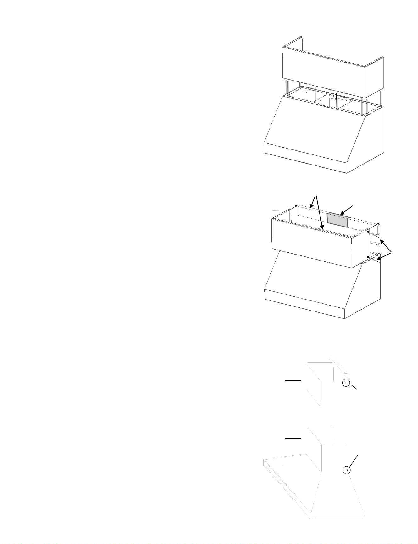
INSTALLATION INSTRUCTIONS
Models starting with “MH”
1. Follow Step 2 of installation instructions on removing liner
from outer shell.
2. The hood is provided with a preinstalled 3-prong cord to
provide power to the hood and blower.
• If an appropriate outlet is not accessible due to the
installation location, the power cord may be removed at the
liner’s junction box, and the hood may be direct wired to a
dedicated, standard non-GFCI 120V, 10A min circuit.
3. If installing a remote blower (HYEX or ATEX), the blower box
at the base of the duct cover and the transition piece may be
removed and discarded. A separate back-draft damper will
need to be added to the ductwork. The duct work will need to
extend fully into the top of the hood shell and connect to the
liner’s 10” dia. outlet collar. Ensure power cable from remote
blower is routed in space between duct cover and the exhaust
duct, and additional length is provided at the base to allow
connection to the hood’s harness.
4. Four pieces of full-length, 3/8” dia. threaded rod (not
provided) are necessary to secure the hood shell and
associated duct cover to structural framing in the ceiling
above the hood shell. The threaded rod must pass through
the framing or blocking in the ceiling and be secured with a
washer and nut on either side to prevent the threaded rod
from moving up or down. The rod may be in multiple sections
to ease installation but must be appropriately coupled at the
joints between members. It should pass through the holes in
the duct cover at all 4 corners, then through the holes in the
hood shell, and secured with washers and nuts inside the
hood shell. Any excess length will need to be trimmed off to
avoid interference with the liner when it is reinstalled.
5. Ensure the lower hood shell is level, then anchor it to the wall.
Lag screws into the wall behind the hood are only needed in
the lower portion of the hood to keep it tight to the wall. Holes
are provided, but additional holes may be added to provide
alignment with structural framing members behind the
wallboard.
6. For in-hood blower(s):
a. Mount the blower(s) into duct cover / internal blower
box using hardware provided.
b. Plug the connector(s) from the liner’s harness into the
blower(s)
7. For remote blower, connect cable from blower to the 3-
position terminal on the liner’s harness. (See step 4.5)
8. Re-install liner using Step 5 from installation instructions.
Take care to route power cord and blower cables to avoid
pinching during liner reinstallation.
Duct cover
3/8” diameter
threaded rod
(4 pieces)
Internal blower box
(may be removed if
using a remote blower)
Transition
Lower
hood shell
In-Hood
Blower(s)
16
2. power cord
junction box
2. power cord
6b. Blower harness(es)
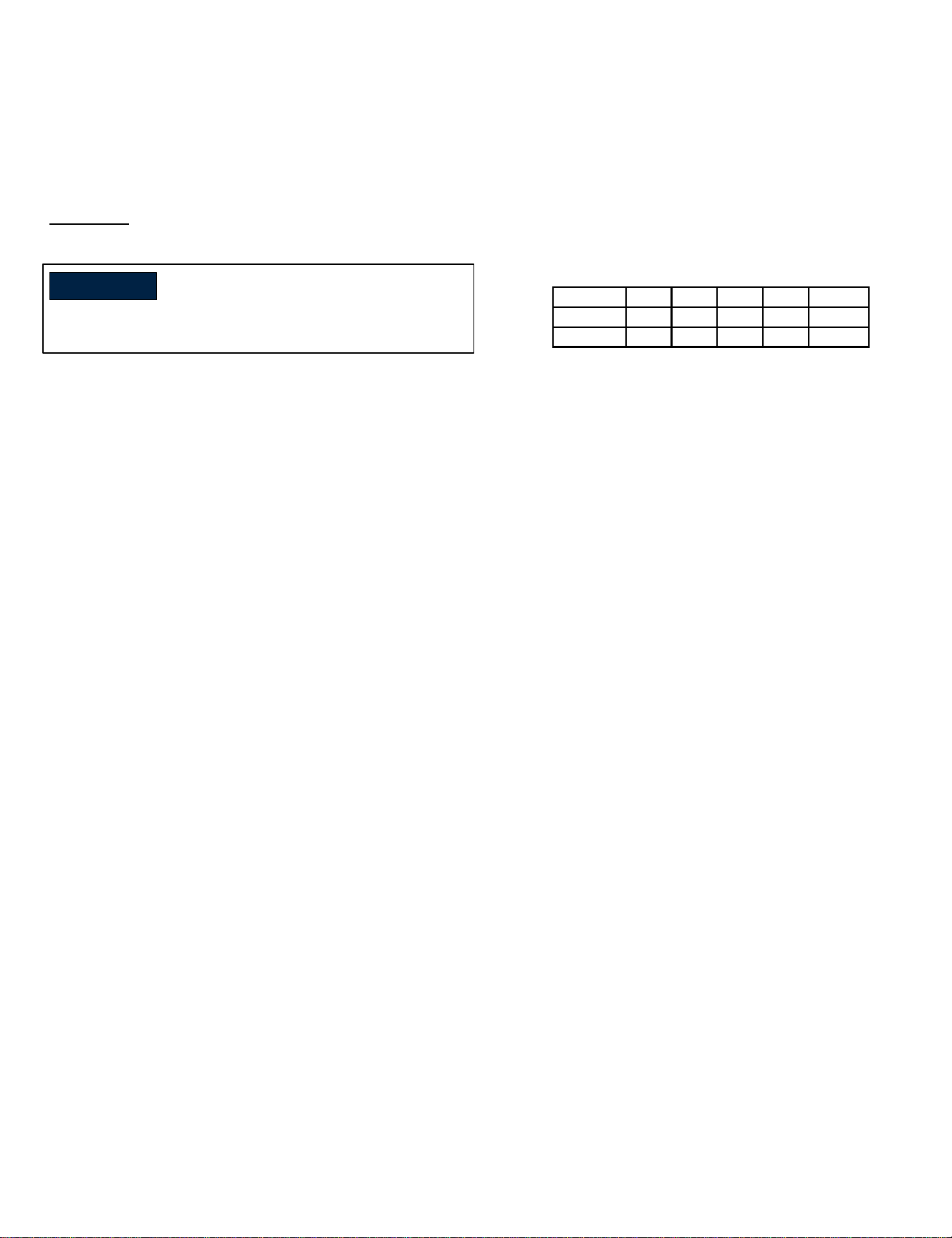
USE & CARE INSTRUCTIONS
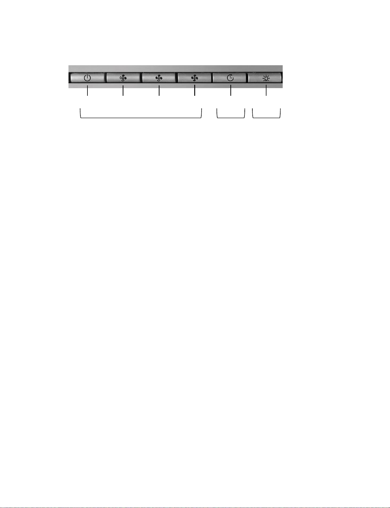
Control Panel
A B C D E F
Blower
Controls
Light
Controls
Timer
Blower Controls:
A – Blower power on, power off, low speed
B – Blower middle speed
C – Blower high speed
D – Blower Boost function*
*After 7 minutes of operation, the blower will
automatically move to high speed (C). The Boost
icon will blink while active.
Additional Controls:
E – Timer
Pressing button during blower operation will
cause blower to run for 15 minutes at its current
speed, and then automatically shut off. The timer
icon will blink while active.
If timer icon is blinking when the blower is not
running, this indicates the filters are due to be
cleaned. Clean the filters as directed, then press
and hold for 3 seconds to reset the filter clean
reminder.
F – Light On/Off plus Dimming Feature
Press and release to turn light on or off. Press
and hold to adjust light intensity. Release when
light reaches desired intensity. Selected intensity
will stay in controller memory until changed.
17

The function of the baffle filters is the absorption of grease particles that form during cooking. Do not operate
ventilation hood without filters in hood. Baffle filters should be examined periodically to assure that the
surfaces and parts are clean.
IMPORTANT
USE & CARE INSTRUCTIONS
Baffle Filters
Removing Baffle Filters:
• Hold both handles located on the filter.
• Pull towards front of hood to depress spring system.
• Pull back of filter down and away from hood.
Removing Grease Trough:
Grease trough is located at base of baffle filters in rear of hood (Figure 1).
• Turn wing fastener(s) ¼ turn to release.
• Pull trough towards front of hood careful not to spill contents inside.
Removing Inner Shield:
Inner shield is located behind baffle filters (Figure 2).
• Remove screws attaching shield to ventilation hood liner.
Figure 1
Figure 2
Cleaning Baffle Filters and Grease Trough:
The baffle filters are dishwasher safe or can be cleaned in a sink with warm, soapy water. Do not use caustic
detergent to clean the filters. Abrasive cleaners may harm or damage the finish. Do not disassemble the
baffle filter. Disassembly will void the warranty.
The grease trough should be cleaned with dish soap and warm water. Depending on the size of the hood, it
may be cumbersome to wash the tray in a kitchen sink. Spraying with a grease cutting cleaner for kitchen use
and rinsing with a garden hose in an open area may be the easiest way to clean the tray. Be sure to rinse
thoroughly and allow to dry completely before reinstalling.
Your hood must be kept clean and maintained properly
• Do not use abrasive cleaners, steel wool pads, or abrasive cloths.
• Do not allow grease to accumulate. For best results, wipe the canopy down with a soft cloth and warm,
soapy water.
• The cleaning of the outside of the hood depends on the material used as a decorative exterior. See
following details for hood specific material cleaning instructions.
• Do not use abrasive or aggressive chemicals to clean the interior or exterior of the hood.
Cleaning Interior and Exterior:
18

USE & CARE INSTRUCTIONS
Cleaning the Interior
Clean the interior of the hood using a soft cloth and warm soapy water or denatured alcohol as needed. Do not
clean the electrical parts or blower with liquids or solvents. Allow to dry thoroughly before restoring power.
Cleaning the Exterior
It is important to follow the direction of the metal grain with the cloth. Do not use chemical solvents, aggressive,
grainy or abrasive products or similar products that could damage the surface of the hood. Test in an
inconspicuous location if you are concerned about a particular cleaner. For various finishes, see details below.
• Brushed or Polished Stainless Steel
Clean the exterior of brushed stainless-steel hoods using a soft cloth and quality stainless steel cleaner or
warm soapy water. Follow all label instructions. Do not polish across the grain or in circles.
• Painted with Gloss Finish
Clean the exterior of hood painted with a gloss finish using a soft cloth and quality glass cleaner or warm
soapy water. Follow all label instructions.
• Designer Metals (Brushed Brass, Brushed Copper, Antique Brass, Antique Copper, Pewter and Oil
Rubbed Bronze)
These Designer Metals are treated with a protective clear coat that will prevent them from aging or
discoloring over time. This clear coat will last the life of the hood unless removed by the homeowner.
Clean with a microfiber cloth using Endust, Pledge or similar cleaner. Harsh cleaners such as Brite Boy
will remove the clear coat and the metals will start to age.
• Designer Metals (Polished Brass and Polished Copper)
These Designer Metals are not treated with a protective coating due to a “rainbow” effect it causes on the
metal. These finishes will patina over time without care and need occasional cleaning. Clean with a
microfiber cloth using Endust, Pledge or similar cleaner for regular cleaning. For tough blemishes Brite
Boy can be used with a microfiber cloth, but due to this product being slightly abrasive this should only be
used in select situations.
19
For cleaning the hood, it is recommended to use a soft cloth and a solution of warm soapy water. It is important
that the soap does not contain granules that could scratch the surface. Follow the direction of the metal grain with
the cloth. The cloth must have no buttons or fasteners that could scratch the surface. Do not use chemical
solvents, aggressive, grainy or abrasive products or similar products that could damage the surface of the hood.
Test in an inconspicuous location if you are concerned about a particular cleaner.
Turn off power at the service panel prior to cleaning the hood.
WARNING
