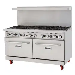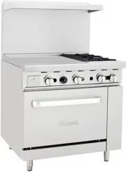

Gas Restaurant Ranges
Operating Instructions
Before you begin, please read these instructions carefully to
use this product correctly, to make the product perform ideally, and
to avoid hazards.
- 1 -
Dear customers and users:
Thank you for purchasing our products. In order to be able to better use
this product, please read these instructions carefully before any operation,
and follow the guide, to avoid any unnecessary trouble during using.
Please keep this instruction manual in a safe place for convenient
reference and operation.
This instruction manual is subject to any change without further notice,
and the manufacturer reserves the right of final interpretation.
The appliance is designed for commercial purposes, not for household
use.
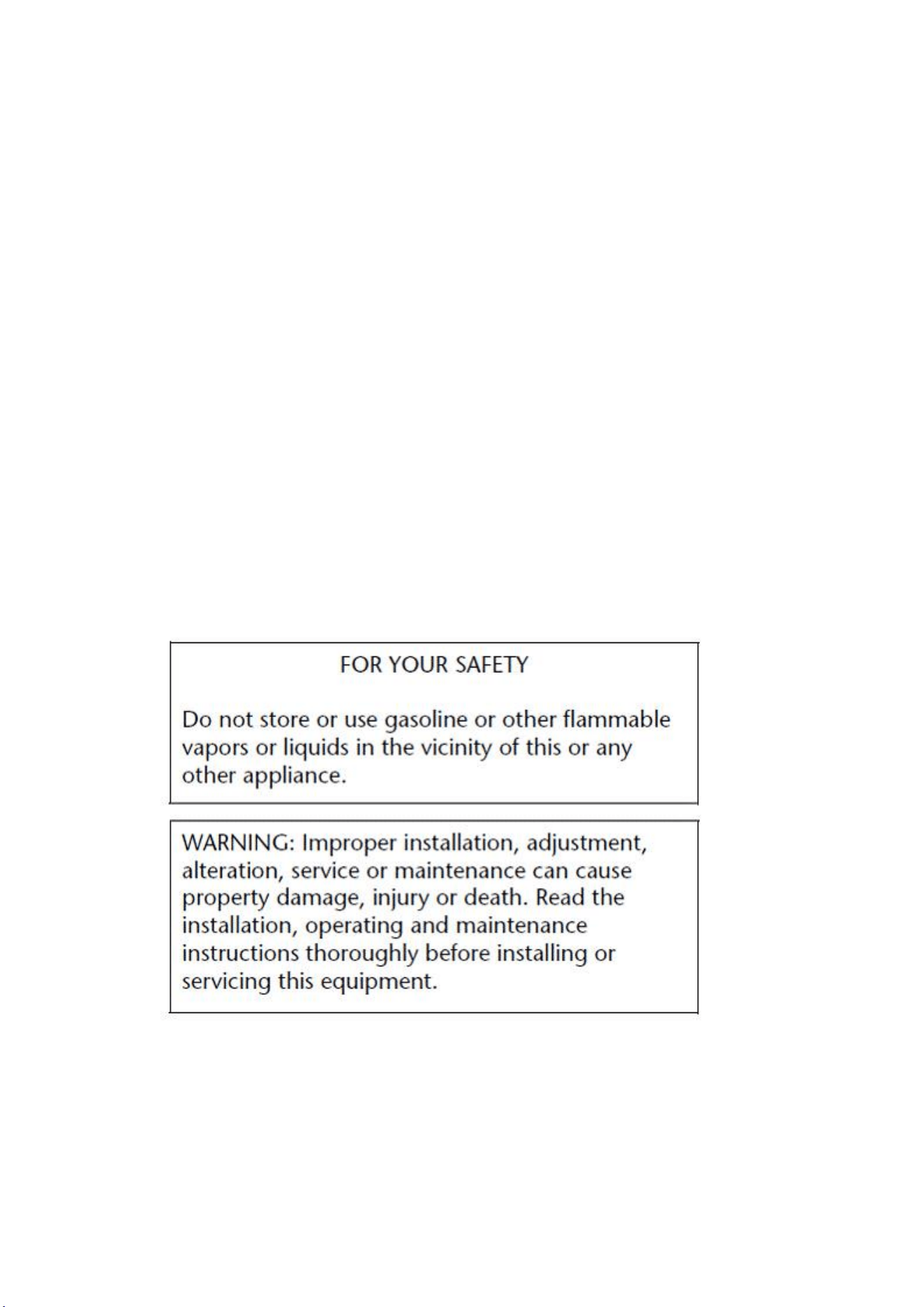
A statement instructing the purchaser to post in a prominent location
instructions to be followed in the event the user smells gas. This
information shall be obtained by consulting the local gas supplier.

- 2 -
Gas Restaurant Ranges
The Installation, Operation and Maintenance Guide
Contents
1. Safety Protection……………………………………………………3
2. Brief Introduction……………………………………………………3
3. Manufacturer's Authority and Responsibility……………………3
4. Parameter Specifications……………………………………………4
5. Transport and Storage………………………………………………22
6. Installation and Debugging…………………………………………23
7. Safety Notices and Precautions……………………………………25
8. Operating Instructions…………………………………………… 26
9. Cleaning and Maintenance …………………………………………30
10. Troubleshooting……………………………………………………32
11.Schematic Diagram for Installation of Rear Panel…………33

- 3 -
1、Safety Protection
Please make sure that the operator is an authorized and licensed
technician before you allow him/her to install and operate the products.
Be sure to strictly follow this instruction guide during installation and
using. The manufacturer is not responsible for any dangers or accidents
caused by improper operation or maintenance.
Do not store flammable or explosive objects around the product. Keep all
flammable and explosive objects at a safe distance away from the product
for normal use.
Place the product in a reasonable position. Regarding related matters
of gas, customer should execute the requirements of local gas supply sector;
If you smell a gas leak, turn off the gas valves immediately and call
the gas company;
The product should not be operated by those under 18 years of age, or
those with physical or mental disorders, or disabilities that lack the
necessary knowledge or experience unless with appropriate instructions and
sufficient safety.
2、Brief Instruction
Such product is the gas restaurant ranges connected with oven and griddle
manufactured by us. The product is in novel design, reasonable structure,
durable and easy to operate and maintain. The ranges include a cast-iron
burner, and griddle and oven include high efficiency stainless steel tubular
burners. A pilot light is equipped, making convenience for igniting the main
fire burner. The oven is equipped with a flame-out protection device, to
ensure the user’s safety in use, The product allows for constant temperature
control and the user can adjust the required temperature as required. It is
an ideal cooking appliance in the industry of hotel, supermarket, western
restaurant, fast food restaurant and food.
3、Manufacture’s Authority and Responsibility
Banning of all or partial transformation to the products without the
- 4 -
manufacturer's explicit authorization.
Manufacturers refused to undertake responsibility to third parties as
the following reasons:
Not follow this instruction guidance and warning in in using and testing;
Not in accordance with the requirements of technical parameters using
this product;
Incorrectly or irrationally using the product by untrained personnel;
Not obey the local law using this product;
Be repaired or changed by unauthorized technicians;
Use the spare parts or accessories provided by non-manufacturers;
Accidents caused by force majeure;
Not strictly comply with related guide of this instruction by any reason.
4、Parameter Specifications
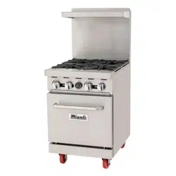
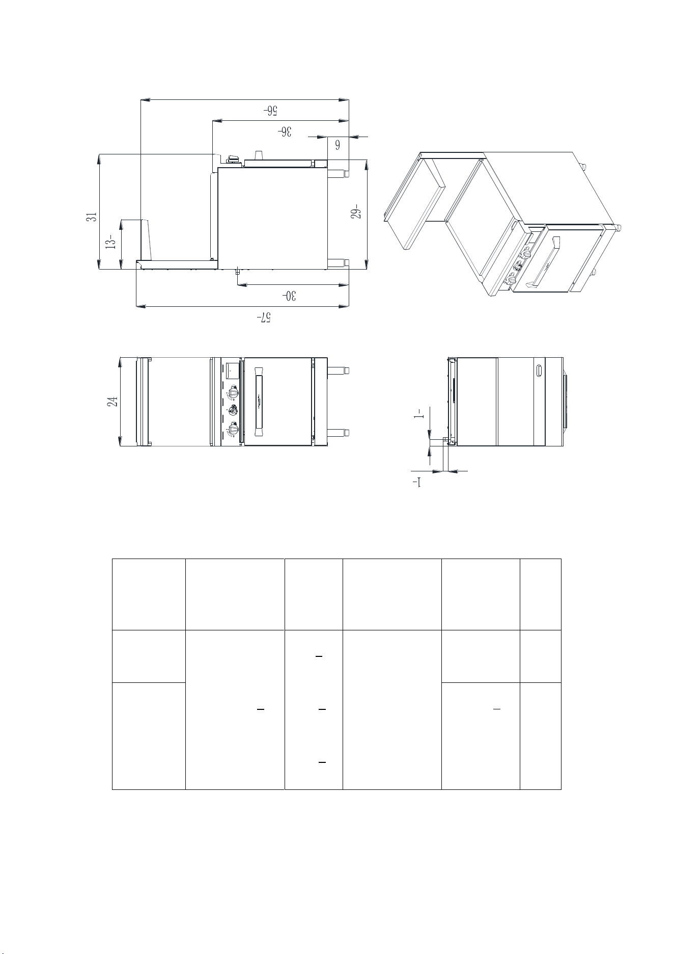
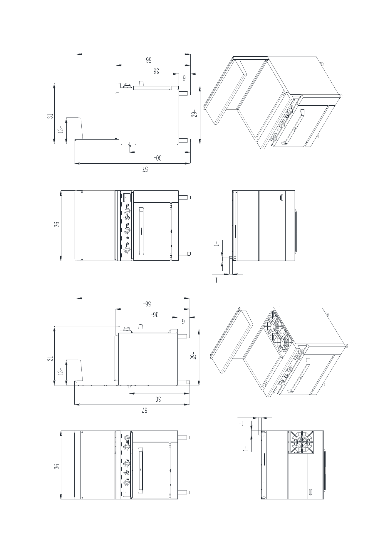
4.1、24 inch series:
3
8
1
2
7
8
1
4
1
8
3
8
7
8
1
2
C-RO4
- 5 -
3
8
1
2
7
8
1
4
1
8
3
8
7
8
1
2
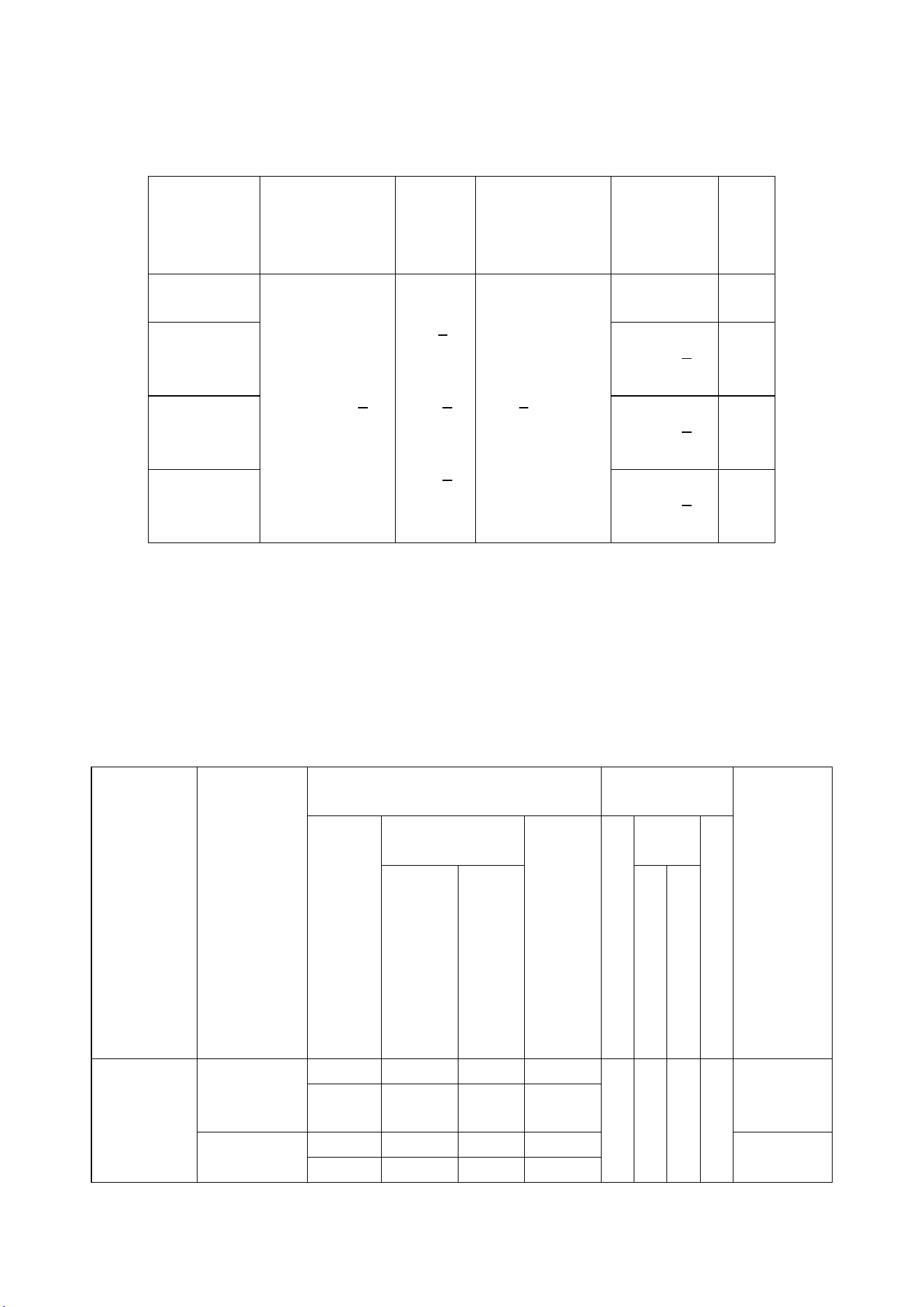
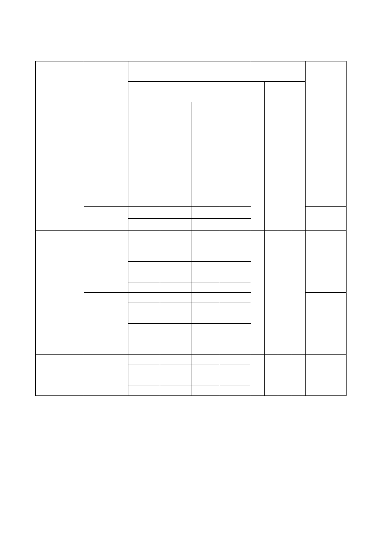
① :Size and package parameter information
<Table 1>
Model
Overall
dimensions(IN)
L x W x H
Packing
size(IN)
L x W x H
Oven
dimensions(IN)
L x W x H
Griddle
working
area(IN)
L x W
Number
of
oven
C-RO4
24*31*57
3
8
26
5
8
*41
3
8
*41
3
8
20*26*14
none
1
C-RO-24G
24*20
5
8
1
C-RO-24G
- 6 -
② :Information of Gas Supply and Burner
The minimum supplied gas pressure regulator is factory set at 5”Natural
Gas W.C, and 10”L.P. Gas W.C. The external thread of product’s intake-tube
is 3/4 inches.
<Table 2>
Model
Gas Species
and Intake
manifold
pressure
(in.W.C.)
Nozzle No. and Per BTU B.T.U./h
Number of
burners
Total BTU
B.T.U./h
Hot
plates
Griddle
Oven
H
o
t
p
l
a
t
e
s
Gridd
le
O
v
e
n
U-
SHAPE
I-
SHAPE
U
-
S
H
A
P
E
I
-
S
H
A
P
E
C-RO4
Natural Gas
5
NG45
NG42
NG45
NG44
4
1
124,000
25,000
27,000
21000
24,000
Propane
10
LP54
LP52
LP54
LP53
116,000
23,000
27,000
21000
24,000
C-RO-24G
Natural Gas
5
NG45
NG42
NG45
NG44
1
1
1
72,000
25,000
27,000
21000
24,000
Propane
10
LP54
LP52
LP54
LP53
72,000
23,000
27,000
21000
24,000
- 7 -
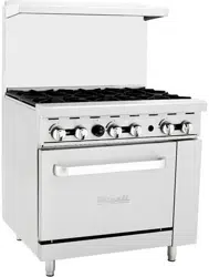
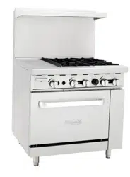
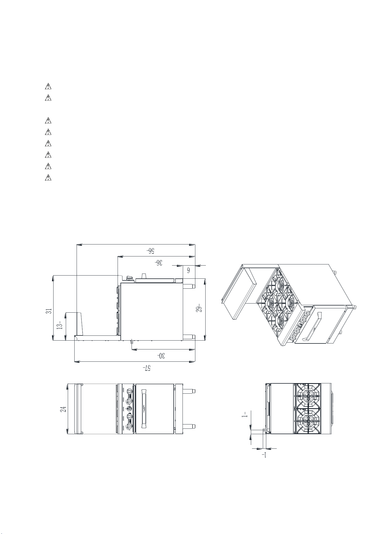
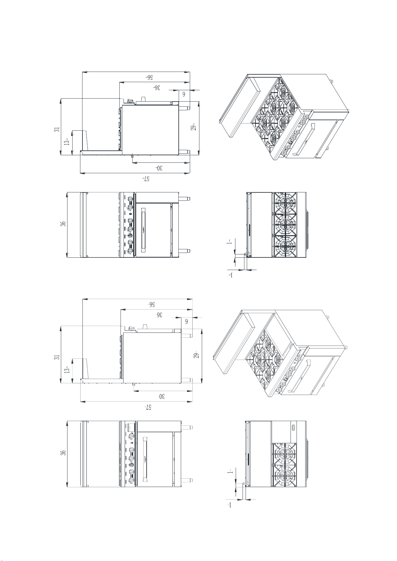
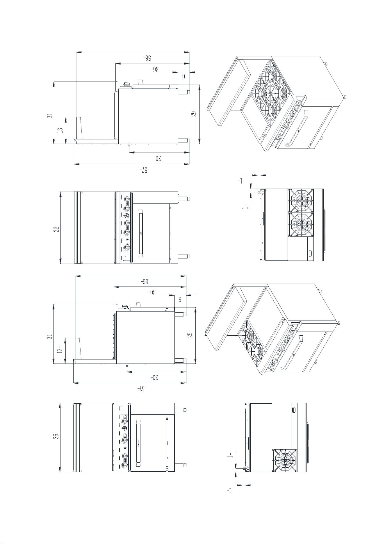
4.2、36 inch series:
7
8
1
2
3
8
1
2
7
8
1
4
1
8
3
8
7
8
1
2
3
8
1
2
7
8
1
4
1
8
3
8
C-RO6
C-RO4-12GR
- 8 -
3
8
1
2
7
8
1
4
1
8
3
8
7
8
1
2
7
8
1
2
3
8
1
2
7
8
1
4
1
8
3
8
C-RO4-12GL
C-RO2-24GR
- 9 -
3
8
1
2
7
8
1
4
1
8
3
8
7
8
1
2
3
8
1
2
7
8
1
4
1
8
3
8
7
8
1
2
C-RO2-24GL
C-RO-36G
- 10 -
①:Size and package parameter information
< Table 3>
Model
Overall
dimensions(IN)
L x W x H
Packing
size(IN)
L x W x H
Oven
dimensions(IN)
L x W x H
Griddle
working
area(IN)
L x W
Number
of
oven
C-RO6
36*31*57
3
8
38
5
8
*41
3
8
*41
3
8
26
1
2
*26*14
none
1
C-RO4-12GR
C-RO4-12GL
12*20
5
8
1
C-RO2-24GR
C-RO2-24GL
24*20
5
8
1
C-RO-36G
36*20
5
8
1
② Information of Gas Supply and Burner
The minimum supplied gas pressure regulator is factory set at 5”Natural
Gas W.C, and 10”L.P. Gas W.C. The external thread of product’s intake-tube
is 3/4 inches.
< Table 4>
Model
Gas Species
and Intake
manifold
pressure
(in.W.C.)
Nozzle No. and Per BTU B.T.U/h
Number of
burners
Total
BTUB.T.U
./h
Hot
plates
Griddle
Oven
H
o
t
p
l
a
t
e
s
Gridd
le
O
v
e
n
U-
SHAPE
I-
SHAPE
U
-
S
H
A
P
E
I
-
S
H
A
P
E
C-RO6
Natural
Gas
5
NG45
NG42
NG45
NG39
6
1
177,000
25,000
27,000
21000
27,000
Propane
10
LP54
LP52
LP54
LP52
165,000
23,000
27,000
21000
27,000
- 11 -
C-RO4-12GR
C-RO4-12GL
Natural
Gas
5
NG45
NG42
NG45
NG39
4
1
1
148,000
25,000
27,000
21000
27,000
Propane
10
LP54
LP52
LP54
LP52
140,000
23,000
27,000
21000
27,000
C-RO2-24GR
C-RO2-24GL
Natural
Gas 5
NG45
NG42
NG45
NG39
2
1
1
1
125,000
25,000
27,000
21000
27,000
Propane
10
LP54
LP52
LP54
LP52
121,000
23,000
27,000
21000
27,000
C-RO-36G
Natural
Gas 5
NG45
NG42
NG45
NG39
2
1
1
102,000
25,000
27,000
21000
27,000
Propane
10
LP54
LP52
LP54
LP52
102,000
23,000
27,000
21000
27,000
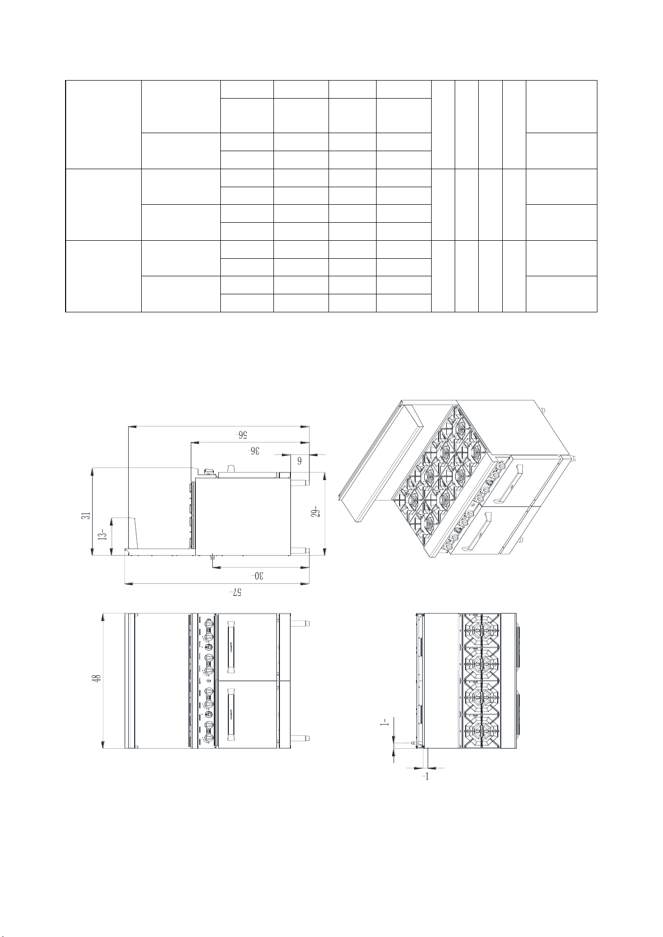
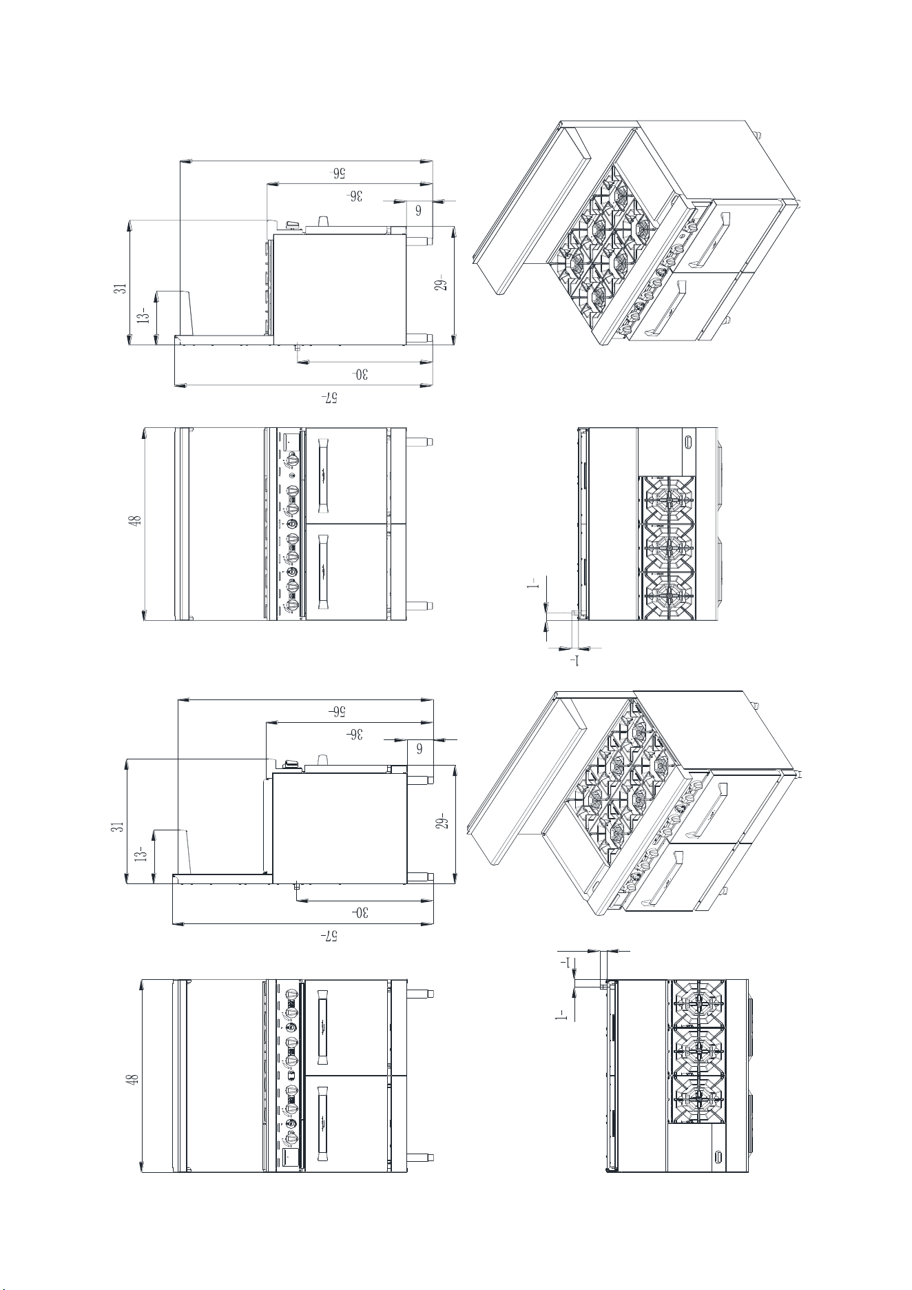
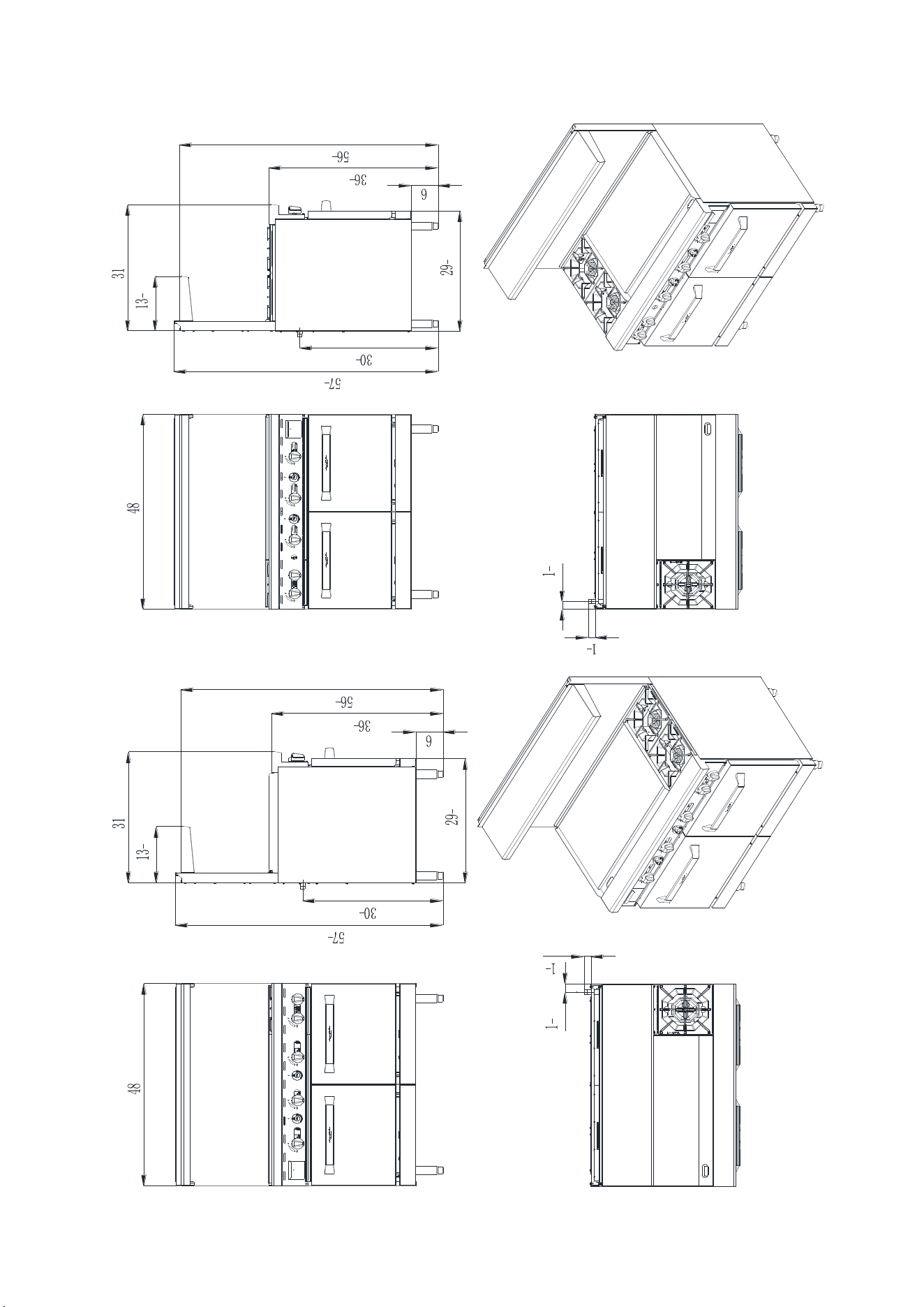
4.3、48 inch series:
7
8
1
2
3
8
1
2
7
8
1
4
1
8
3
8
C-RO8
- 12 -
7
8
1
2
3
8
1
2
7
8
1
4
1
8
3
8
1
4
1
8
3
8
3
8
1
2
7
8
7
8
1
2
C-RO6-12GR
C-RO6-12GL

- 13 -
7
8
1
2
3
8
1
2
7
8
1
4
1
8
3
8
3
8
1
2
7
8
1
4
1
8
3
8
7
8
1
2
C-RO4-24GR
C-RO4-24GL
- 14 -
7
8
1
2
3
8
1
2
7
8
1
4
1
8
3
8
3
8
1
2
7
8
1
4
1
8
3
8
7
8
1
2
C-RO2-36GR
C-RO2-36GL
- 15 -
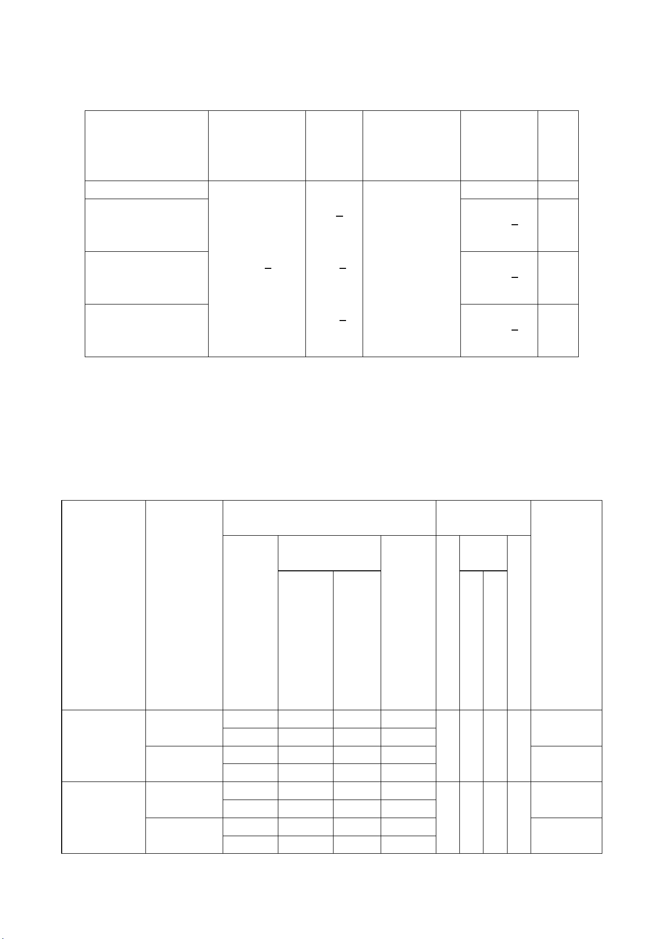
① Size and package parameter information
<Table5>
Model
Overall
dimensions(IN)
L x W x H
Packing
size(IN)
L x W x H
Oven
dimensions(IN)
L x W x H
Griddle
working
area(IN)
L x W
Number
of
oven
C-RO8
48*31*57
3
8
50
5
8
*41
3
8
*41
3
8
20*26*14
none
2
C-RO6-12GR
C-RO6-12GL
12*20
5
8
2
C-RO4-24GR
C-RO4-24GL
24*20
5
8
2
C-RO2-36GR
C-RO2-36GL
36*20
5
8
2
Information of Gas Supply and Burner
The minimum supplied gas pressure regulator is factory set at 5”Natural
Gas W.C, and 10”L.P. Gas W.C. The external thread of product’s intake-tube
is 3/4 inches.
<Table6>
Model
Gas Species
and Intake
manifold
pressure
(in.W.C.)
Nozzle No. and Per BTU B.T.U/h
Number of
burners
Total
BTUB.T.U
./h
Hot
plates
Griddle
Oven
H
o
t
p
l
a
t
e
s
Gridd
le
O
v
e
n
U-SHAP
E
I-SHA
PE
U
-
S
H
A
P
E
I
-
S
H
A
P
E
C-RO8
Natural
Gas 5
NG45
NG42
NG45
NG44
8
2
248,000
25,000
27,000
21000
24,000
Propane
10
LP54
LP52
LP54
LP53
232,000
23,000
27,000
21000
24,000
C-RO6-12GR
C-RO6-12GL
Natural
Gas 5
NG45
NG42
NG45
NG44
6
1
2
219,000
25,000
27,000
21000
24,000
Propane
10
LP54
LP52
LP54
LP53
207,000
23,000
27,000
21000
24,000
- 16 -
C-RO4-24GR
C-RO4-24GL
Natural
Gas 5
NG45
NG42
NG45
NG44
4
1
1
2
196,000
25,000
27,000
21000
24,000
Propane
10
LP54
LP52
LP54
LP53
188,000
23,000
27,000
21000
24,000
C-RO2-36GR
C-RO2-36GL
Natural
Gas 5
NG45
NG42
NG45
NG44
2
2
1
2
173,000
25,000
27,000
21000
24,000
Propane
10
LP54
LP52
LP54
LP53
169,000
23,000
27,000
21000
24,000
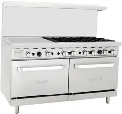
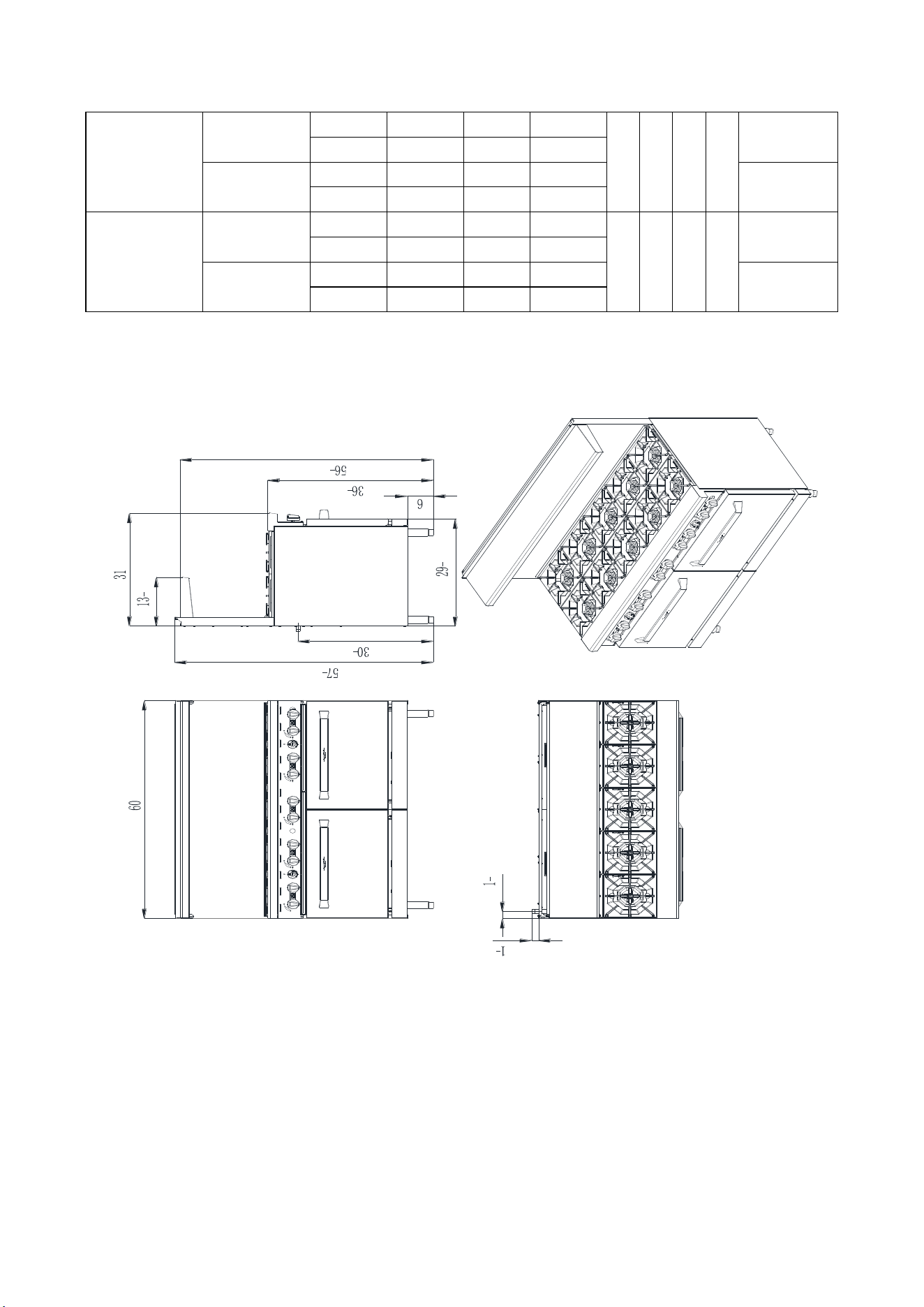
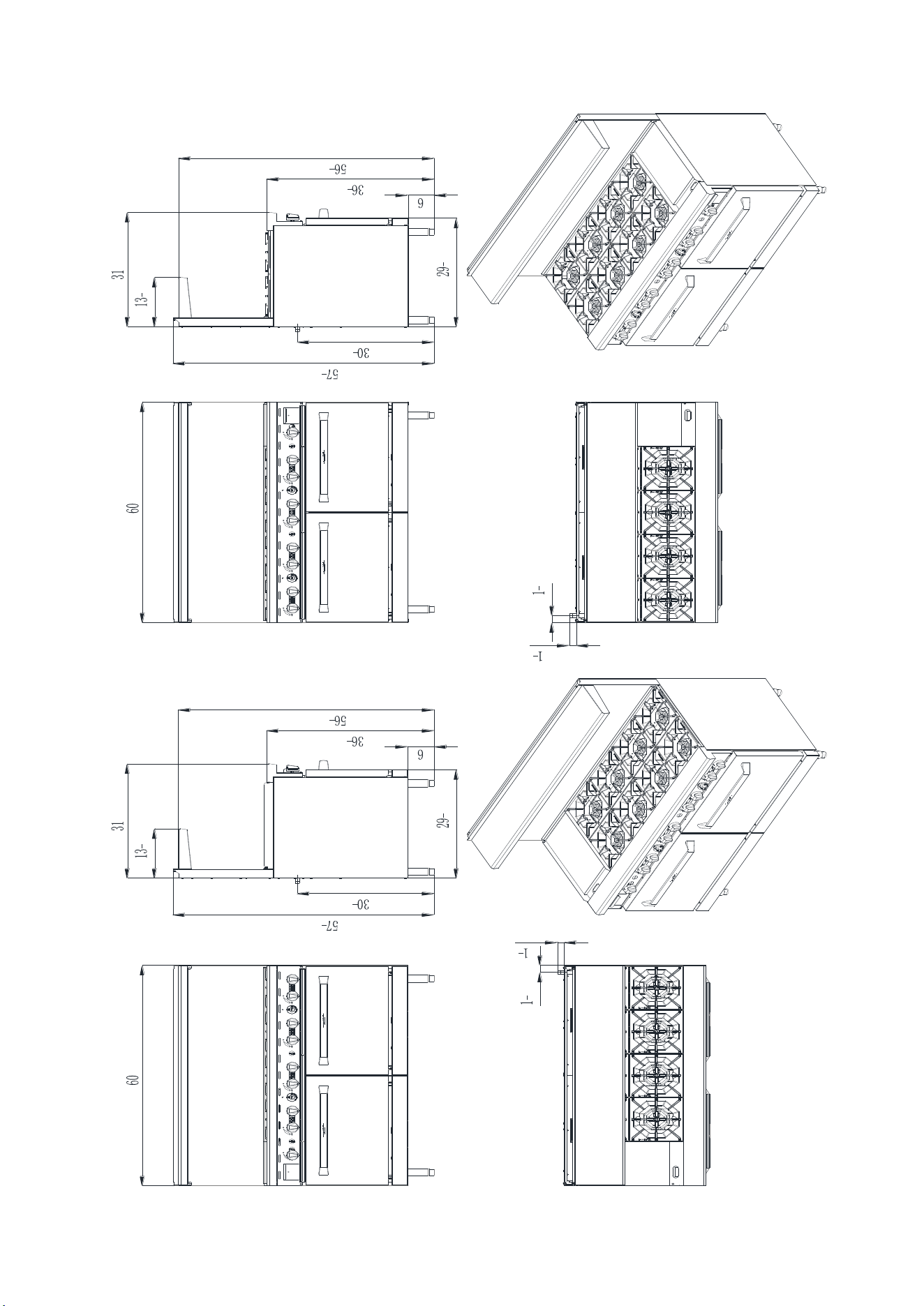
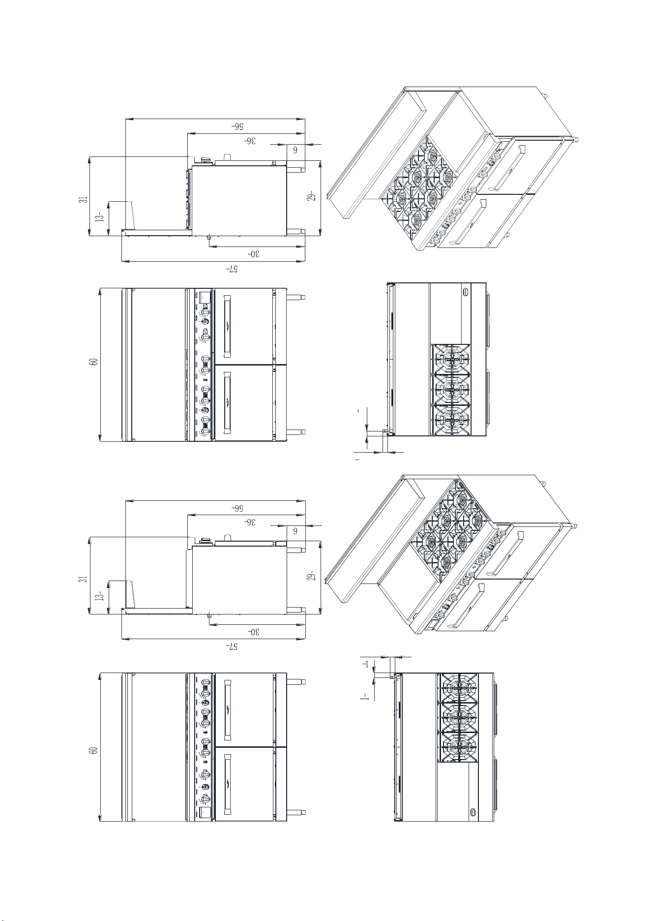
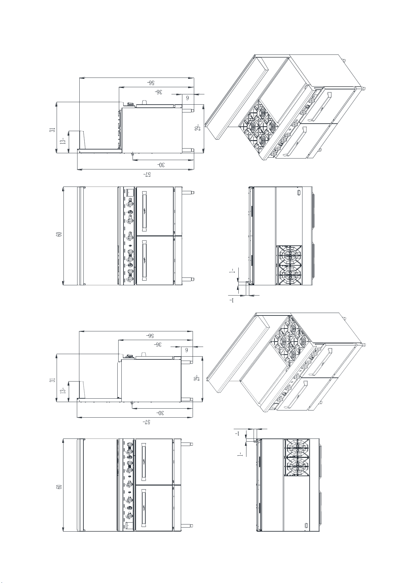
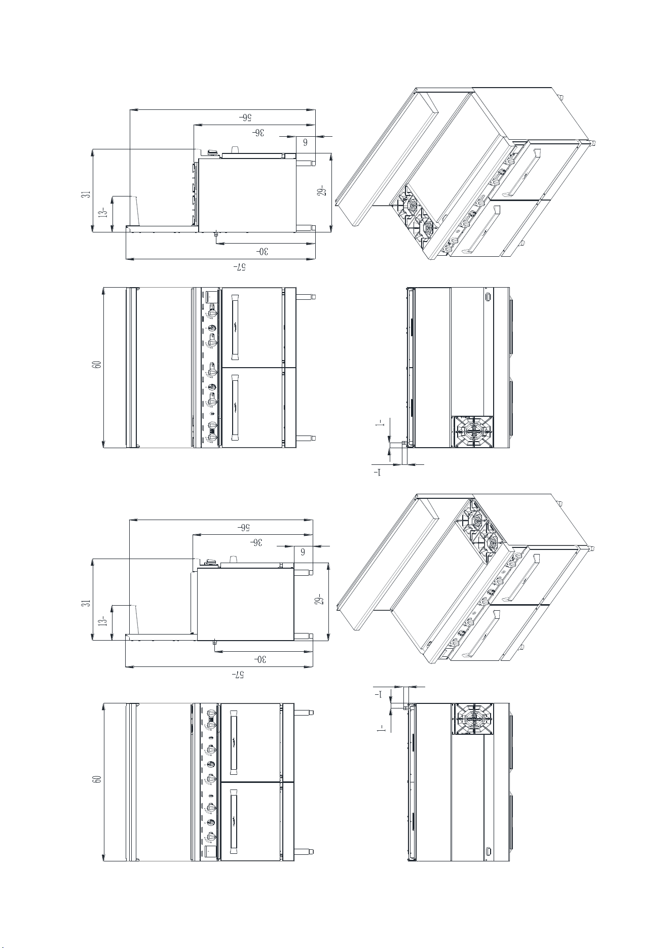
4.4、60 inch series:
3
8
1
2
7
8
1
4
1
8
3
8
7
8
1
2
C-RO10
- 17 -
3
8
1
2
7
8
1
4
1
8
3
8
7
8
1
2
3
8
1
2
7
8
1
4
1
8
3
8
7
8
1
2
C-RO8-12GL
C-RO8-12GR
- 18 -
3
8
1
2
7
8
1
4
1
8
3
8
1
1
2
1
7
8
3
8
1
2
7
8
1
4
1
8
3
8
1
2
7
8
C-RO6-24GR
C-RO6-24GL
- 19 -
7
8
1
2
3
8
1
2
7
8
1
4
1
8
3
8
3
8
1
2
7
8
1
4
1
8
3
8
7
8
1
2
C-RO4-36GR
C-RO4-36GL
- 20 -
C-RO2-48GL
7
8
1
2
3
8
1
2
7
8
1
4
1
8
3
8
3
8
1
2
7
8
1
4
1
8
3
8
7
8
1
2
C-RO2-48GR
- 21 -
①:Size and package parameter information
<Table7>
Model
Overall
dimensions(IN
) L x W x H
Packing
size(IN)
L x W x H
Oven
dimensions(IN)
L x W x H
Griddle
working
area(IN)
L x W
Number
of
oven
C-RO10
60*31*57
3
8
62
5
8
*41
3
8
*41
3
8
26
1
2
*26*14
none
2
C-RO8-12GR
C-RO8-12GL
12*20
5
8
2
C-RO6-24GR
C-RO6-24GL
24*20
5
8
2
C-RO4-36GR
C-RO4-36GL
36*20
5
8
2
C-RO2-48GR
C-RO2-48GL
48*20
5
8
2
② Information of Gas Supply and Burner
The minimum supplied gas pressure regulator is factory set at 5”Natural
Gas W.C, and 10”L.P. Gas W.C. The external thread of product’s intake-tube
is 3/4 inches.
- 22 -
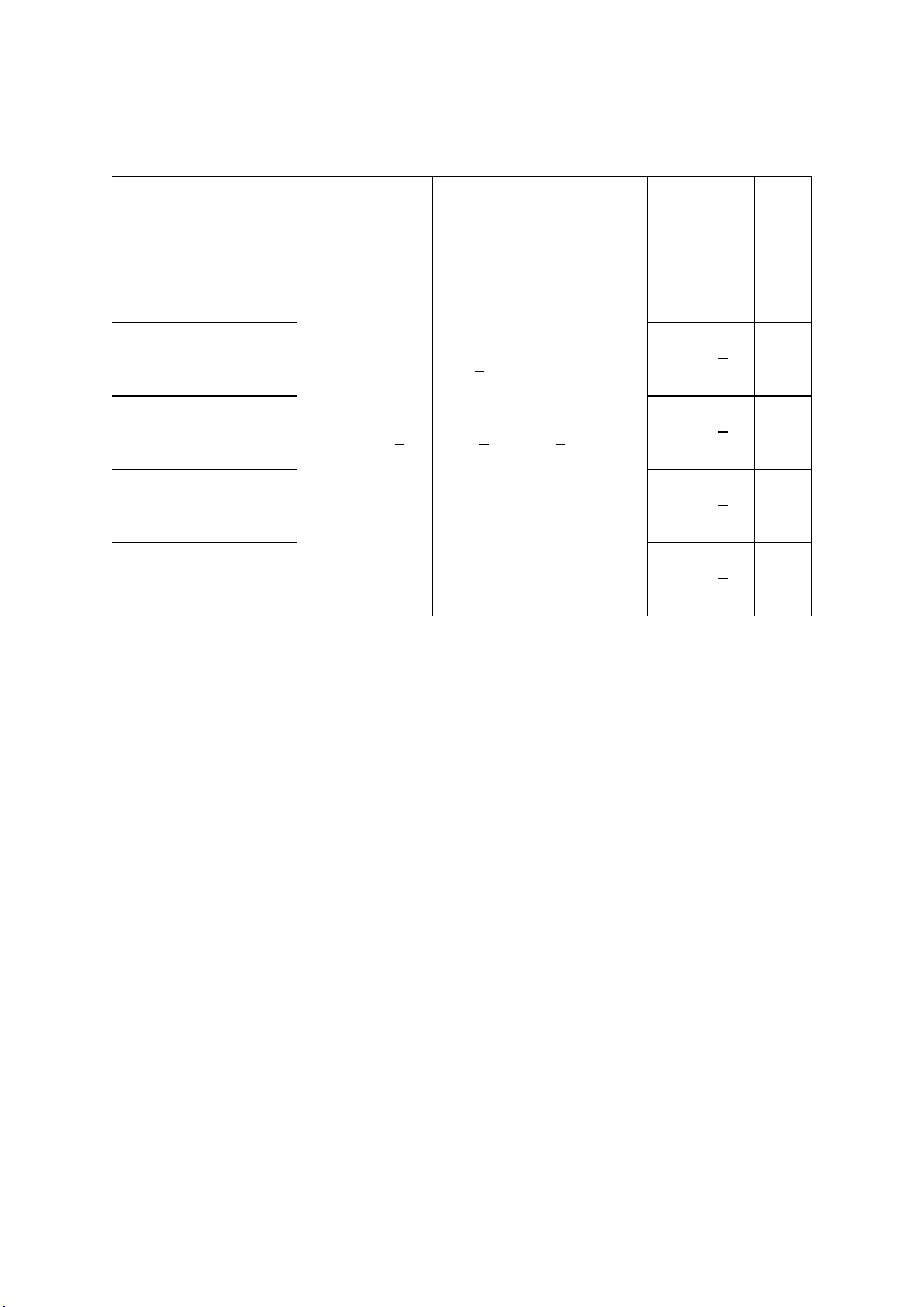
<Table8>
Model
Gas Species
and Intake
manifold
pressure
(in.W.C.)
Nozzle No. and Per BTU B.T.U/h
Number of
burners
Total
BTUB.T.U
./h
Hot
plates
Griddle
Oven
H
o
t
p
l
a
t
e
s
Gridd
le
O
v
e
n
U-SHAP
E
I-SHA
PE
U
-
S
H
A
P
E
I
-
S
H
A
P
E
C-RO10
Natural
Gas 5
NG45
NG42
NG45
NG39
1
0
2
304,000
25,000
27,000
21000
27,000
Propane
10
LP54
LP52
LP54
LP52
284,000
23,000
27,000
21000
27,000
C-RO8-12GR
C-RO8-12GL
Natural
Gas 5
NG45
NG42
NG45
NG39
8
1
2
275,000
25,000
27,000
21000
27,000
Propane
10
LP54
LP52
LP54
LP52
259,000
23,000
27,000
21000
27,000
C-RO6-24GR
C-RO6-24GL
Natural
Gas 5
NG45
NG42
NG45
NG39
6
1
1
2
252.,000
25,000
27,000
21000
27,000
Propane
10
LP54
LP52
LP54
LP52
240,000
23,000
27,000
21000
27,000
C-RO4-36GR
C-RO4-36GL
Natural
Gas 5
NG45
NG42
NG45
NG39
4
2
1
2
229,000
25,000
27,000
21000
27,000
Propane
10
LP54
LP52
LP54
LP52
221,000
23,000
27,000
21000
27,000
C-RO2-48GR
C-RO2-48GL
Natural
Gas 5
NG45
NG42
NG45
NG39
2
3
1
2
206,000
25,000
27,000
21000
27,000
Propane
10
LP54
LP52
LP54
LP52
202,000
23,000
27,000
21000
27,000
5. Transport and Storage
In the process of transportation, handle carefully and keep upright to
prevent damage of the product packing. Wrapped equipment should not be in
open air for a long time, and shall be placed in a well-ventilated and
non-corrosive gases warehouse. When equipment needs temporary storage,
rainproof measures should be taken.
- 23 -
6. Installation and Debugging
Any erroneous installation, adjustment, refit, overhaul or maintenance
may cause property damage or personal injury. The work shall be performed
by authorized and licensed technicians, otherwise the manufacturer has the
right not to provide warranty service;
Only be installed in accordance with the local code. If no similar
standard, you should conform to the National Fuel Gas Code, ANSI Z223.1/NFPA
54, the National Gas Installation Code, CSA-B149.1, or the L.P. Gas
Installation Code, CSA-B149.2 as applicable;
The appliance individual shutoff valve must be disconnected from the gas
supply piping system during any pressure testing of that system at test
pressures in excess of 1/2psi (3.45kPa).
6.1、Unpacking and Installation
Please dispose of all packaging materials and residues after unpacking;
Check the equipment. If it is damaged, please keep wrappers and receipts
which must be signed by the carrier representative (Driver), and contact the
carriers to pursue a claim within 15 days after receiving;
Be sure to install supporting legs before using, and do not tear up any
label or logo before normal using;
Please read these instructions carefully before installation and
operation. Please contact your local agent if you have any questions;
Such stove shall be installed on the horizontal, solid, anti-skidding
and incombustible floor, and at the water-proof working area with sufficient
light and far away from the children and customers;
The installation position is a well-ventilated place in accordance with
the local regulations;
The charbroiled must be installed under the matched cooking fume exhauster
according to the local regulations;
Important: Installation and ventilation laws, and codes are very
different, you should state and comply with all codes of the National Fire
Protection Association Inc when it comes to requirements for installation
of equipment;
Screw 4 adjustable stainless steel legs in the tapping hole with four
corners of the charbroiled bottom, ensure sufficient space for ventilation;
Adjustable stainless steel legs to make the equipment level, and get the
- 24 -
same level with other series of the same stove; Please lift the equipment
rather than drag if you need to move it;
Please refer to P16“11. Schematic Diagram for Installation of Rear
Panel” for the installation methods of rear panel.
Supplied gas pressure regulator is factory set at 5”Natural Gas W.C,
and 10”L.P. Gas W.C;
The equipment can only be placed on the noncombustible floor,and keep
a distance of at least 6 inches(152mm) to equipment’s both sides and back,
and keep a distance of at least 6 inches(152mm) to the bottom;
Do not put anything around the equipment, and on the counter top and bottom,
in order to avoid influencing combustion and air circulation;
Leave enough distance in front of the equipment to take apart the control
panel. All major parts, in addition to the burner remove from the front
intake-tube;
It may be necessary to adjust the balance of air input by authorized and
licensed technicians;
Thread glue must be resistant to the action of liquefied petroleum gases.
Warning! Use soap water or testing instrument to test whether piping
joint leaks or not before using, and forbid using an open flame to test!
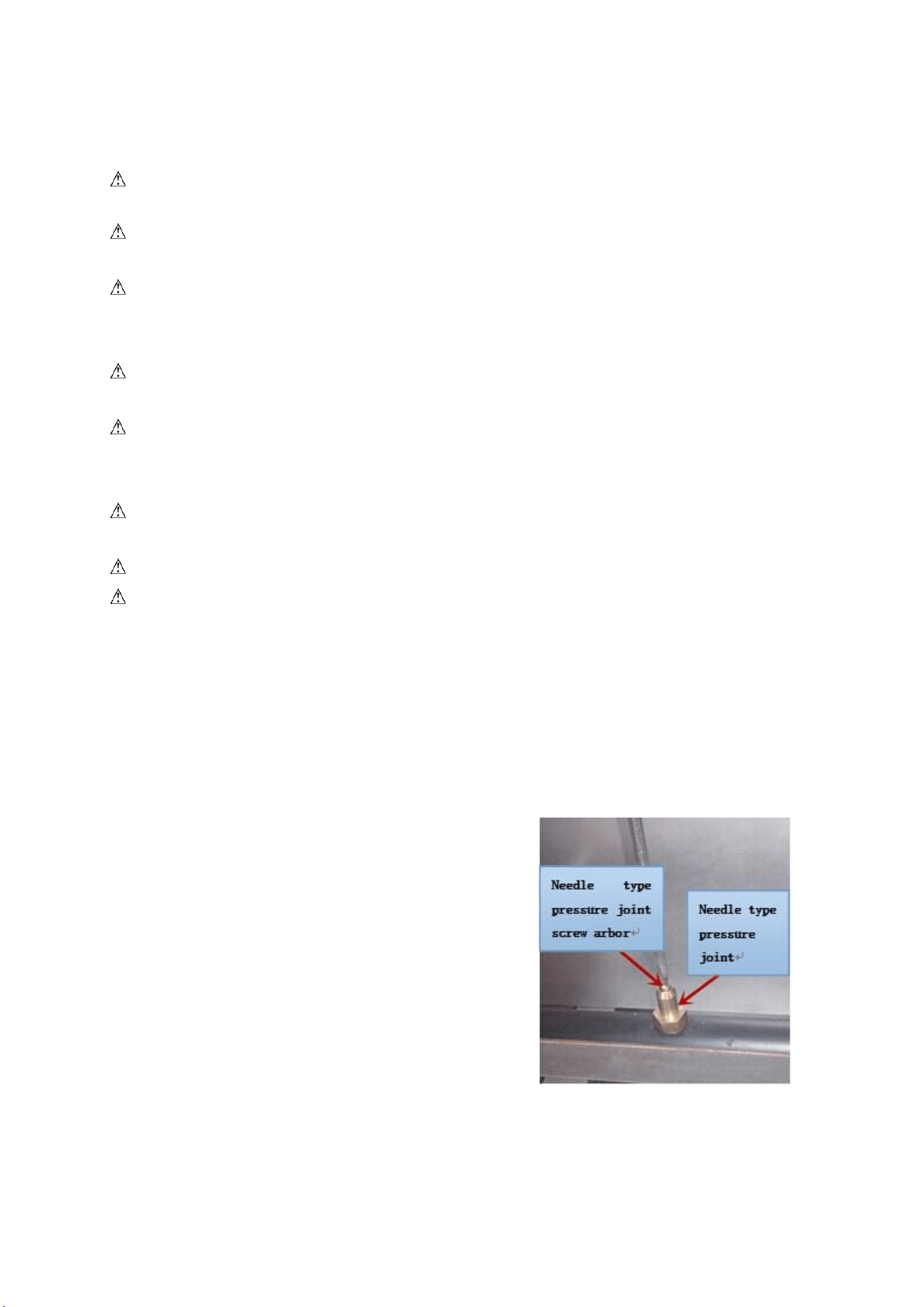
After installing completely, you should check gas supply pressure. Use
a pressure gauge which is equipped with liquid (such as U-type pressure
gauge, the minimum value is 0.1mbar) or a digital pressure gauge to
test. Steps are as following:
●Remove top panel, and needle type pressure joint screw arbor (Fig.1),
then slip rubber tube of pressure gauge
over needle type pressure joint;
●Start the equipment in accordance with
the instructions, measuring gas supply
pressure (dynamic pressure) in the work
state;
●Access to the equipment if measured data
within the limits of Table 1, otherwise,
you will need to adjust gas pressure
regulating valve or contact gas supplier
to bargain; Figure 1
●Unplug pressure gauge after you accomplish pressure testing, then
install needle type pressure joint screw arbor. Important: must screw

- 25 -
joint screw arbor, to prevent gas escape!
6.2 Debugging
It’s very important to debug the new stove. Through the comprehensive
system test of equipment, we can ensure function and safety performance of
products. Discovering any potential problems before use (such as
equipment’s placement, ventilation, operation, etc), can avoid costly
losses.
7. Safety Notices and Precautions
Warning! For your safety, do not place petrol and other flammables nearby.
Please keep clean and free of flammables surroundings. (Read ANSI Z83.14B,
1991 for reference)
Warning! Any erroneous installation, adjustment and refit may cause
property damage or personal injury and maintenance failure. Read the
instructions carefully before installation and using.
Warning! Operation instruction must be placed in a conspicuous location.
When customers smell gas in the process of using, should take safety
precautions immediately. Immediately turn off the main gas valve, extinguish
all heat and flames, and call 911. Safety information can be obtained from
your local gas suppliers.
When using this equipment, safety precautions should always
be followed, including the following:
The burner of gas restaurant ranges, stove frame, griddle and external
surface will still be scalding after being used. You must take care when
touching these positions;
Do not directly touch the burner, stove frame and griddle when the gas
restaurant ranges and griddle are operating;
Turn off the equipment as repairing, maintaining and cleaning;
If the equipment has any problems of equipment damage, gas piping leaks,
igniter or valves damage, or lose product accessories, do not operate, and
call for the service immediately;
The use of attachments not recommended or sold by the manufacturer may
cause fire, personal injury or even death;
Do not use out of doors;
Such appliance is used to cook, fry and bake the food and shall not be
- 26 -
used for other purposes;
The equipment does not contain any user-serviceable parts. Dealers or
technicians will repair it. Do not take apart any spare parts without
authorization;
Never change any other parts without authorization to this equipment,
otherwise, may cause hazards, and the manufacturer has the right not to
provide warranty service;
Steel cutting producers used to manufacture with sharp edges. The
manufacturer has dealt with these sharp edges during production, however,
we insist the operator take care when in contact with this piece of equipment;
Always keep hands, hair and clothing away from heating source.
Wait the unit cools down before cleaning. Because the unit is too hot
to handle after using.
8. Operating Instructions
Before operating, make sure to place the unit horizontally by adjusting
bottom adjustable legs, and place the catch tray properly.
The pilot light has been set at the factory. Each burner has a pilot light.
Make sure air circulation well at the bottom of equipment;
Do not use fan or air-conditioning blowing at the flame, in order to avoid
extinguishing flame and cause safety accidents;
Install the matched cooking fume exhauster according to the local
regulations of char broiler;
Make sure to keep the natural air circulation in the kitchen.
8.1 Lighting the pilot light
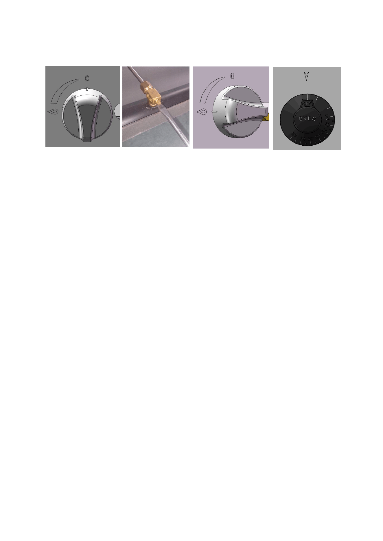
Turn the control valve at the position of “0”(Fig.2), make sure all
knobs are in the close state. Light and hold an ignition source at the pilots.
The pilot light may not be lighted immediately, for existing gas in the pipe.
Wait a minute, the pilot light will be lighted after the gas extinguished.
Tips: You can use a screwdriver to adjust the height of the flame (Fig.3).
8.2 Igniting the main burner
Revolve the main fire control valve knob anticlockwise after lighting
the pilot light, then the main fire burner is lighted by the pilot light.
The power of burner increases as revolving angel increases. When knob reaches
to " ", burner is in the maximum power (Fig.4).
- 27 -
Figure 2 Figure 3 Figure 4 Figure 5
8.3 Lighting of normally open fire of stove
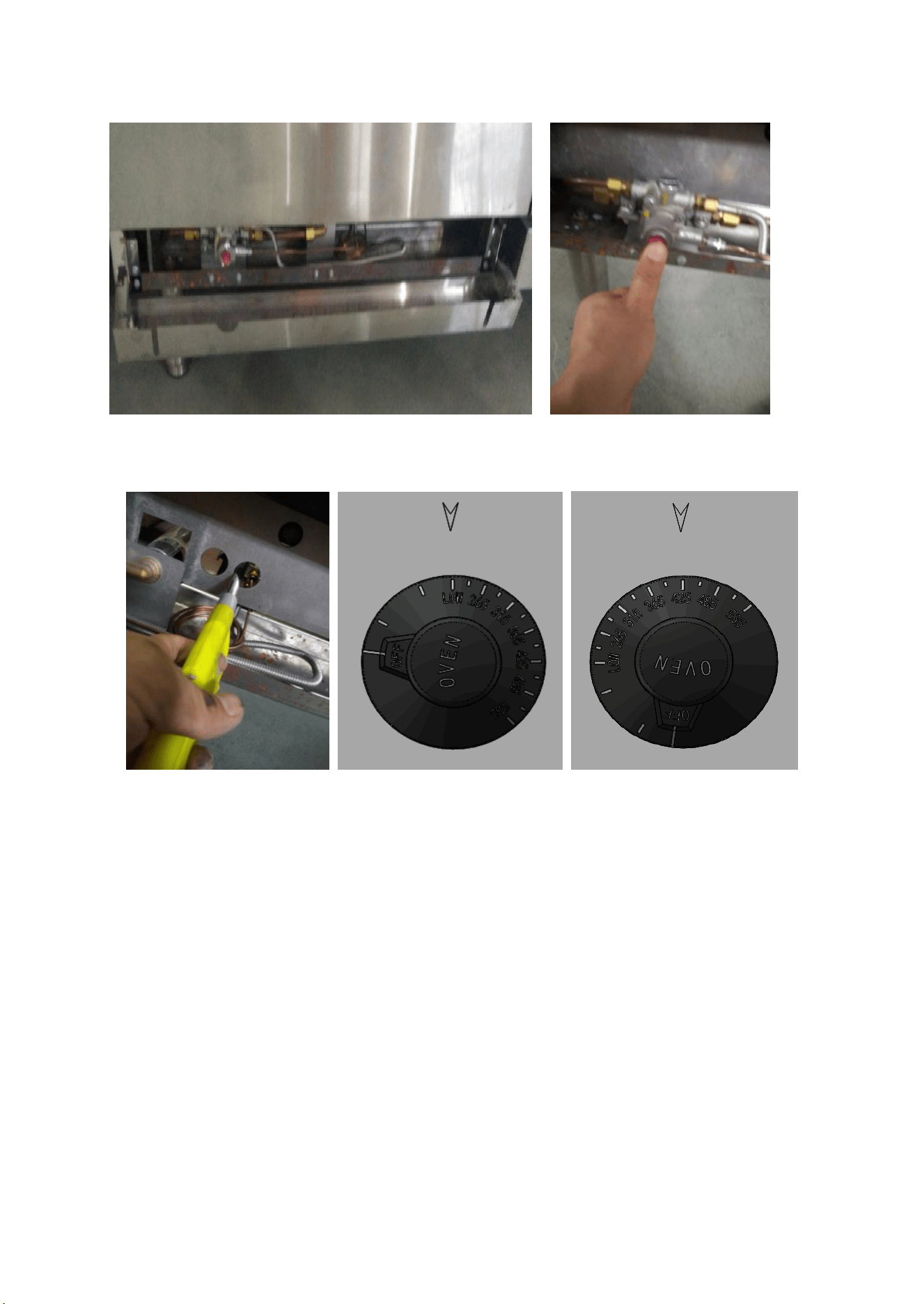
1. Align the OFF indicative line of thermostat valve knob to the arrow (Figure
5) to close the valve.
2. Open the underside face plate of oven (figure 6), thoroughly press the button at the
front end of safety valve, and ignite the pilot fire by lighter with another hand
simultaneously (figure 7 and figure 8). Do not loosen the button immediately after
the pilot gas is ignited. Down-press it for 10 – 15 seconds. Then, loosen the button
to observe whether the pilot fire is stable.
3. If the pilot fire is not ignited, please repeat the procedure above until the pilot fire is
ignited.
Tip 1:The pilot light may not be lighted immediately, for existing gas
in the pipe. Wait a minute, the pilot light will be lighted after the gas
extinguished.
Prompt 2: Turn on and off the normally open fire of oven with slot type
screwdriver (figure 3).
- 28 -
Figure 6 Figure 7
Figure 8 Figure 9 Figure 10
8.4 Ignition of main fire of oven
After the normally fire was ignited, the main fire valve of safety valve was opened, and press
the thermostat valve knob to rotate to the position LOW counterclockwise (figure 9). At this
moment, the oven burner is ignited. Rotate the thermostat valve knob counterclockwise
continuously to the required temperature (figure 10) and the oven starts warming. When
reaching the set temperature, the thermostat valve will automatically adjust the gas flow to
keep the temperature in the oven constant.
8.5 Turn off the valve
Revolve the control valve knob clockwise to "0" (Fig.2, Fig.5), so that
extinguish flame of the main burner, but the pilot light still works.
After turn off the equipment, the main fire should be stop more than
5 minutes before next use.
- 29 -
8.6 Stove Operation
Before using the stove for the first time, please use a mild detergent
to wipe it clean. Do not use corrosive or abrasives detergent.
Turn the burners on about 15-20 minutes before broiling for preheating,
according to the cooking requirement to adjust the flame size.
Notice: When first preheating, the furnace will smoke above. This is
caused by protective lipids on the grates and other parts are heated, it
is normal, and it will be eliminated after the power up to the maximum for
burning an hour.
8.7 Adjust air input
① Hot plates:Remove control panel,
unscrew damper solid screw(Fig.11),
revolve damper left to right(Fig.12),
meanwhile, observe flame, to adjust an
appropriate opening degree. Then screw
damper solid screw, make sure the
equipment will not get loose in the
process of moving and translation.
Reinstall control panel.
②:Griddle:Remove control panel,
unscrew damper solid screw(Fig.13),
revolve damper left to right(Fig.14),
meanwhile, observe flame, to adjust an
appropriate opening degree. Then screw
damper solid screw, make sure the
equipment will not get loose in the
process of moving and translation.
Reinstall control panel.
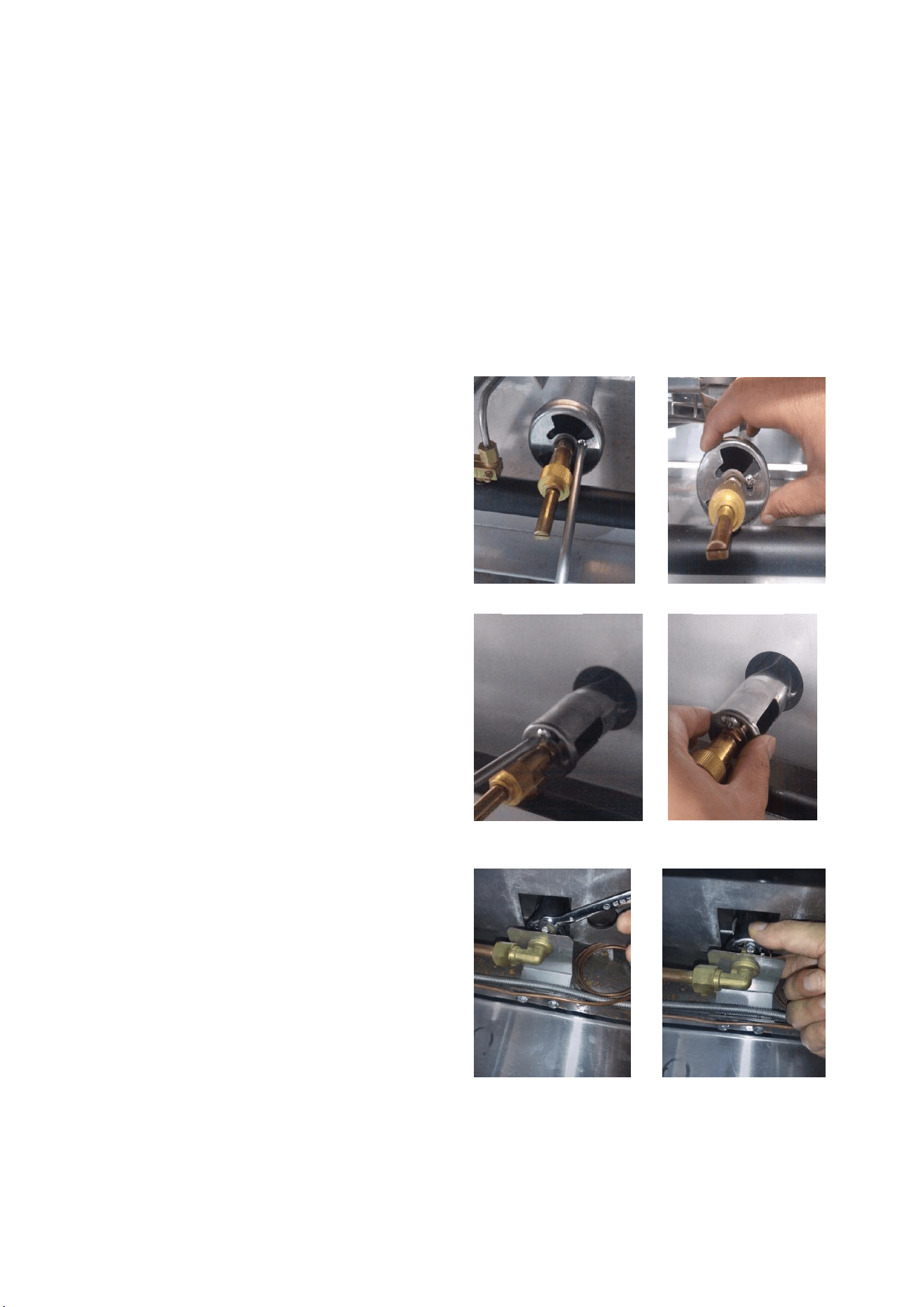
③: Oven: Open the underside face plate
of oven (figure 6), loosen the fastening
screws of damper(figure 15) and rotate
the damper horizontally (figure 16).
Meanwhile, observe the flame. Adjust the damper to the appropriate opening
Figure13
Figure14
Figure15
Figure15
Figure12
Figure11
Figure16
Figure15
- 30 -
angle. Then, tighten the fastening screw bolt of damper to guarantee the
appliance does not get loose. At last, reinstall the underside face plate
of oven.
④Caution: Each burner damper has been adjusted before delivery (once air
input), Normal use without adjustment but only switching gas. Adjust only
by authorized and licensed technicians.
9. Cleaning and Maintenance
Do not use any abrasive or flammable detergent to wipe;
Do not hose down, immerse or pressure wash any part of the cooker,
excluding the catch tray;
Do not use abrasive cleaning matters to wash, even not use corrosive
detergent!
Grill cleaning/maintenance:
(1) when grill cools down, use a cloth with cleaning agent to wipe unit
surface and residue;
(2) use a cloth with water to wipe unit surface;
(3) burning the main fire burner about 10-20 minutes for sterilization;
(4) no use for long time, spread cooking oil on grill after cleaning.
Warning: Before cleaning, all control valves must be turned
off. Strictly follow the lighting instructions to work again
after cleaning!
Warning: Wait for the equipment to cool down after the unit
has been turned off before you clean!
Cut off the gas source when not in use;
If the equipment is not used for a long time, clean the surface by wiping
it with a soft cloth and place it in a well-ventilated area;
Comprehensively check the equipment at least once every year by
authorized and licensed technicians;
The product is made of 90% metals, and can not be discarded everywhere.
Deal with it in accordance with the local codes.
Instructions to clean appliance regularly with recommended cleaning
agents, if necessary.

- 31 -
Recommended cleaning methods
<Table9>
Items
Methods
Times
Body
Wipe it with a soft cloth and mild
detergent;
daily
Control panel
Turn off valves when not in use;
Wipe panel and control valve knob with
mild detergent.
daily
Catch tray
Pull out catch tray from front body
until the equipment cools down. Use a
cloth with cleaning agent to wipe unit
surface, wipe up residue. Reinstall
after cleaning.
Warning: if the catch tray is permitted
to fill too high, should be cleaned!
Per use
Oven
After the appliance is cooled, open the
oven door to take out the net rack, and
use the clean duster cloth to dip
detergent to clean the grease and other
rubbish debris. After cleaning up,
reinstall the net rack to the original
position. Take care when taking out the
net rack and cleaning the internal part
of stove, for fear to damage the enamel
coating of oven inner wall.
Per use
- 32 -
10. Troubleshooting
<Table 10>
Problems
Possible causes
Problem solving
Not lighting
1.Insufficient gas
pressure in pipe
1.Contact the local
gas supply dept.
2.Nozzle occlusion
2.Dredge nozzle
Ignite the pilot
light but not the
main fire
1.Insufficient gas
pressure in pipe
1.Contact the local
gas supply dept.
2.The main fire nozzle
occlusion
2.Dredge nozzle
3.Gas control valves
have problems
3.Change gas
control valves
4.The pilot light and the
main fire’s distance is too
far
4.Adjust the
distance of them
5.Flame is too low
5.Adjust the height
of the pilot light
Close gas and
heard a sound of
fire
1.Insufficient gas
pressure in pipe
1.Contact the local
gas supply dept.
2.Not match nozzle aperture
with gas resources
2.Adjust nozzle
diameter
3.Flow of connection
pipe is not enough
3.Increase pipe’s
allowable flow
4.Damper opening
degree is too large
4.Adjust damper
Yellow flame and
black smoke
1.Use bottom gas
1.Change gas
2.Not match nozzle aperture
with gas resources
2.Adjust nozzle
diameter
3.Not enough air to ignite
3.Increase damper
opening degree
4.In the peak of using
gas, sources of gas
float heavy
4.Turn down valves
flow. Turn it up
after the peak
The problems mentioned above are only for reference. If any fault occurs, please
stop using, and contact technicians to check and repair. Safety first, turn
off the power and gas supply before maintenance.
- 33 -
Note
1、Pressure maintaining valve connects with air intake, must be installed by
authorized and licensed technicians, to ensure interface tightness.
2、The pressure regulator(s) have connected, the maximum load of natural gas
cannot exceed 6”, and of LP cannot exceed 12”.
3、Adjustment range of the pressure regulator(s) is 3”-6”for natural gas, and
5”-12”for L.P..
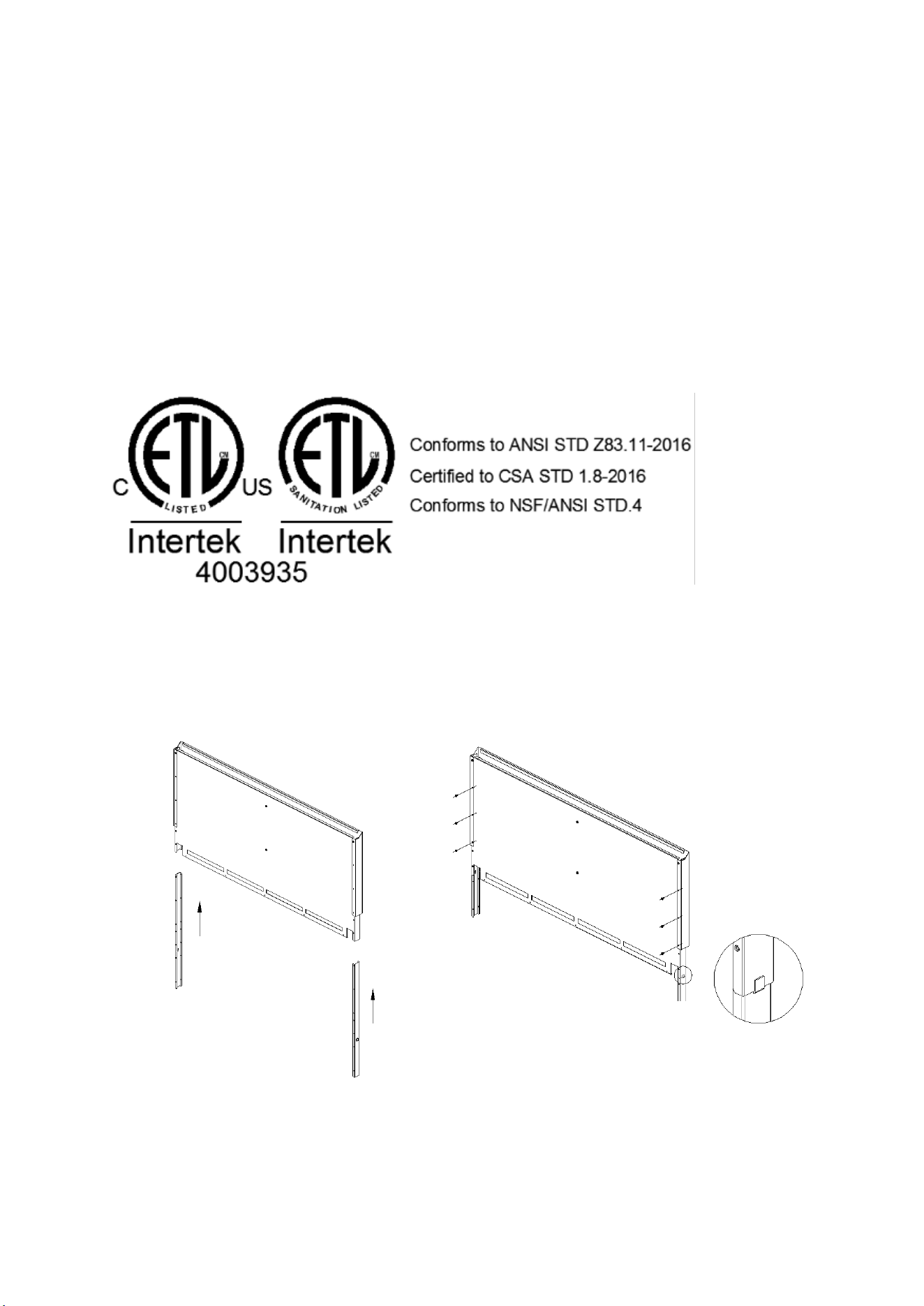
11. Schematic diagram for installation of back panel
Step I
(Insert the inserted bar of
rear panel into the
corresponding position of
rear panel)
Step II
(Fix the inserted bar of rear panel
with the rear panel by
self-tapping screw)
- 34 -
Migali Industries, Inc.
Trusted Since 1955
516 Lansdowne Ave
Camden, NJ 08104
Service Call: 800.852.5292
Service Email: [email protected]
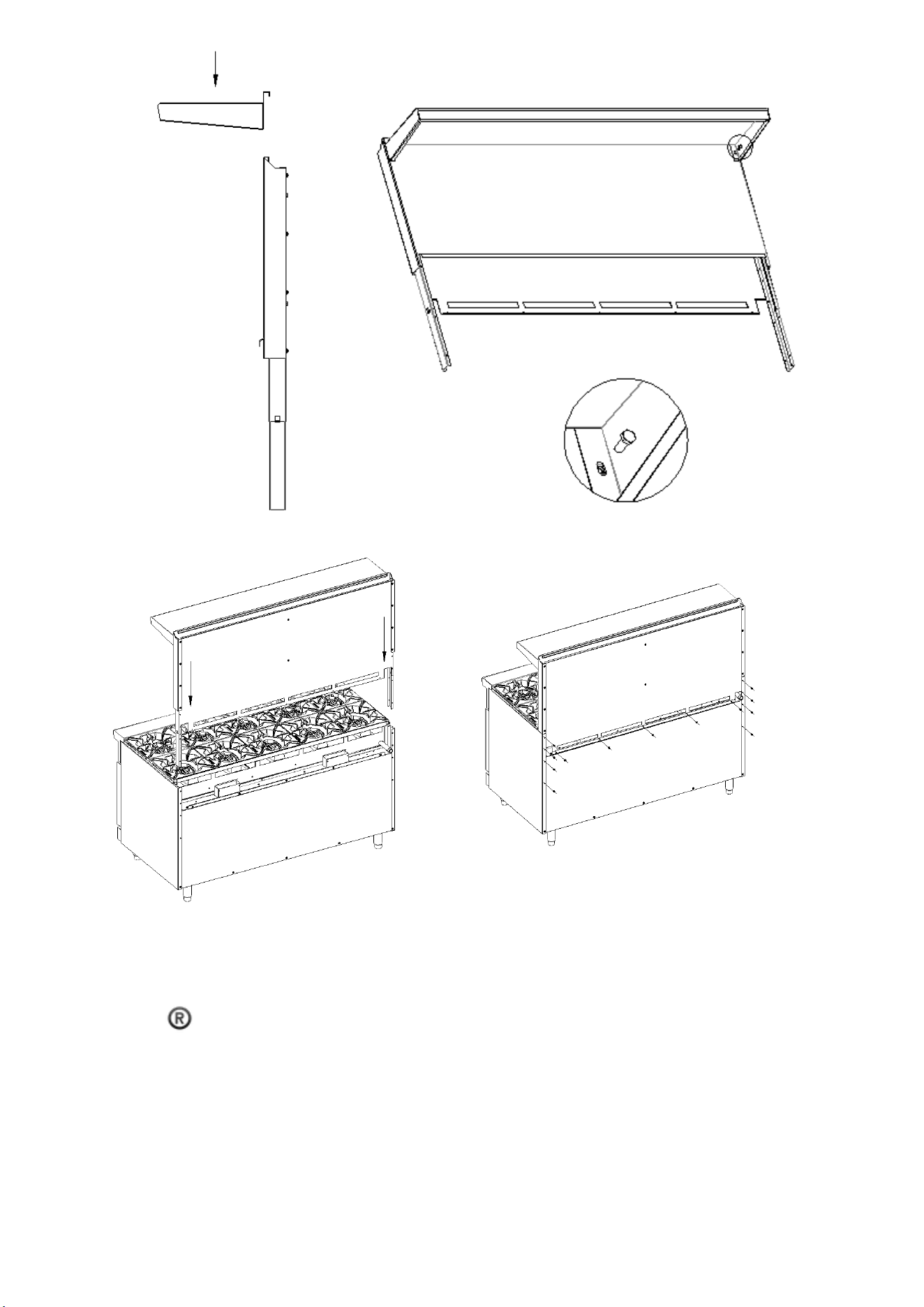
Step III
(Fasten the rear top plate at the
corresponding position of rear
panel)
Step IV
(Fix the rear top plate with rear
panel by hexagon bolt)
Step V
( Insert the assembled rear top
plate into the corresponding
position of stove body)
Step VI
(Fix the assembled rear panel
with the stove body by
self-tapping screw)