Model No. DG1.V2, DG2.V2
Thank you for purchasing a Dellonda product. Manufactured to a high standard, this product will,
if used according to these instructions, and properly maintained, give you years of trouble free performance.
Original Language Version
DG1.V2, DG2.V2 Issue 3 21/10/24
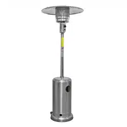
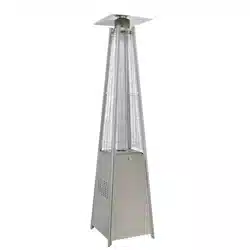
Dellonda 13KW Outdoor Garden Gas Patio Heater for
Commercial & Domestic use
Specication
Introduction
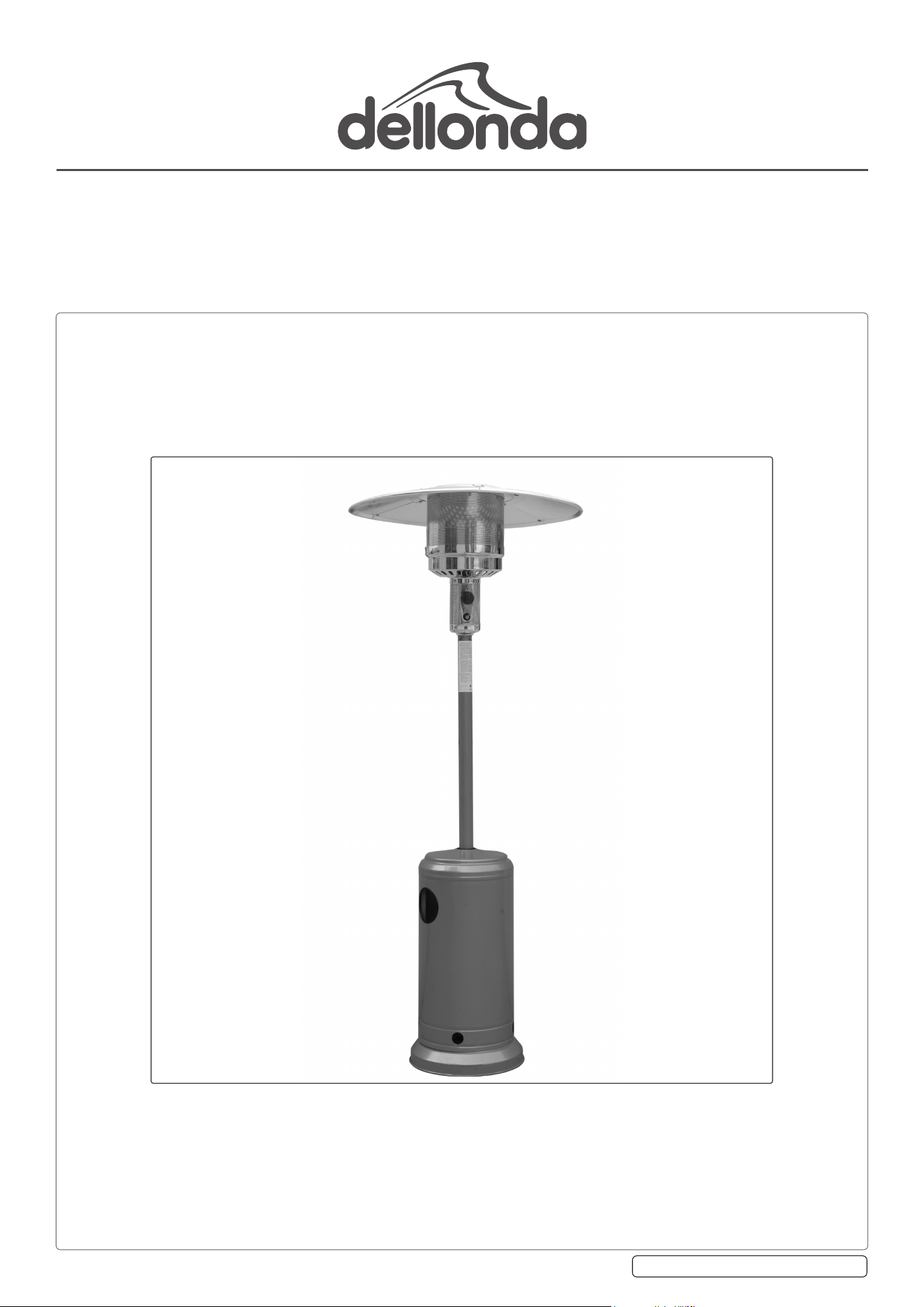
Innovative design of radiant gas tower patio heater. This traditional freestanding patio heater produces a pleasant, heated working/relaxing
environment and is ideal for both commercial and domestic settings including open workshops, boat yards, patios, forecourts, gardens and
terraces. The burner head is positioned approximately 2.19m off the ground and the metal reector directs radiation downwards and outwards.
Variable heat output controls make it fully adjustable. The unit features a fully enclosed gas cylinder chamber and safety tip-over switch.
Supplied with wheels for easy manoeuvrability, regulator and hose assembly for use with propane patio gas bottles and is available in black
or stainless steel. This product should only be used in a well ventilated area. Maximum Gas Bottle Size (W x H): Ø325 x 700mm. Some simple
assembly is required.
Safety InstructionsSAFETY
9 Read the installation, operating and maintenance instructions thoroughly before installing or using this equipment.
9 Keep the instructions for future reference.
9 If there is a smell of gas: shut off the gas to the appliance, extinguish any open ames. If odour continues contact gas supplier.
8 DO NOT store or use petrol or other ammable substances inside the housing of the heater.
8 DO NOT store or use petrol or other ammable liquids or gases in the vicinity of the heater.
8 DO NOT store a gas cylinder that is not connected for use in the vicinity of this or any other appliance.
WARNING! DO NOT use indoors. For use outdoors or in amply ventilated areas.
An amply ventilated area is one that has a minimum of 25% of the surface area open, see g.1.
(The surface area is the sum of the wall surface).
WARNING! Not intended to be installed in recreational vehicles and/or boats.
WARNING! Improper installation, adjustment, alteration, service or maintenance can cause injury or
property damage.
9 Installation and repair must be carried out by a qualied person.
9 This product must be installed and the gas cylinder stored in accordance with the local regulations in
force.
8 DO NOT obstruct the ventilation holes of the cylinder housing.
8 DO NOT move/transport the appliance when in operation. Shut off the gas cylinder or the regulator before moving.
8 DO NOT move/transport the heater until it has cooled down.
9 Use only the type of gas and the type of cylinder specied by the manufacturer.
9 The LP cylinder used with the patio heater must meet the following size requirements:
Diameter 32.5cm x height 70cm, 15kg maximum capacity.
9 Protect the product from strong wind to prevent tilting. In case of violent wind precautions must be taken against tilting of the
appliance.
9 Only use on level ground capable of withstanding the weight of the heater.
8 DO NOT remove the injector (it is not removable). It is forbidden to convert the appliance from one gas pressure to another gas
pressure.
9 Use only the type of gas specied in the instructions.
9 The whole gas system (hose, regulator, pilot or burner) should be inspected for leaks or damage before use and at least annually, by a
Suitably qualied person.
8 DO NOT modify this product. Parts sealed by the manufacturer or his agent shall not be manipulated by the user.
9 All leak testing should be done with a soap solution. Never use an open ame to check for leaks, refer to section 'leakage test'.
8 DO NOT use the heater until all connections have been leak tested.
9 Turn off the gas immediately if a gas smell is detected. Turn cylinder valve OFF. If the leak is at the hose/regulator connection tighten
the connection and perform another leak test. If bubbles continue appearing contact your supplier. If the leak is at the regulator/
cylinder connection disconnect from cylinder, reconnect and perform another leak check. If soap bubbles are still seen, cylinder valve is
defective. Return cylinder to its place of purchase.
Important Information
Please read these instructions carefully. Note the safe operational requirements, warnings & cautions. Use the product correctly and with care
for the purpose for which it is intended. Failure to do so may cause damage and/or personal injury and will invalidate the warranty. Keep these
instructions safe for future use.
Refer to
Instruction
Manual
Wear protective
gloves during
assembly
Model no’s DG1.V2 DG2.V2
Fuel consumption: 928g/hr
Fuel Type: Propane
Heated area: 10m²
Output: 13kW
Dimensions (W x H): 810 x 2190mm
Max. gas bottle size (W x H): Ø325 x 700mm
Product Depth (Front to Back): 81cm
Product Dimensions (W x D x H): 810 x 810 x 2190mm
Product Height (Floor to Top): 219cm
Product Width (Side to Side): 81cm
Weight: 15Kg
g.1
9 Keep the ventilation opening of the cylinder enclosure free and clear of debris.
9 Turn off gas supply at the cylinder after use.
8 DO NOT paint the radiant screen, control panel or top canopy reector.
9 Control compartment, burner and circulation air passageways of the heater must be kept clean.
9 Turn off gas whilst not in use.
9 LP regulator/hose assembly must be protected from accidental damage.
9 Any guard removed for servicing/maintenance must be replaced before operation.
9 Keeps adults and children away from the high temperature surface to avoid burns of ignition of clothing.
WARNING! Accessible parts may be very hot. Keep young children away.
9 Children should be carefully supervised when in the vicinity of the heater.
8 DO NOT hang clothing or other ammable materials on the heater or place them near the heater.
WARNING! Change the gas cylinder in an amply ventilated area, away from any ignition source (candle, cigarettes, other ame
producing appliances).
Gas Supply Installation
9 Unscrew and remove the protective plug from the valve outlet if one is tted on the gas cylinder.
9 Check the bullnose connection on the regulator for any damage before connecting. Make sure regulator is clear of any debris.
9 Check condition of hose especially at nozzle end.
9 Ensure regulator is in the o position to allow regulator to be tted to the gas cylinder.
9 Attach regulator onto gas cylinder, pull regulator upward to check the tting is secure.
9 To remove regulator ensure gas tap is in the o position. (Fig. 2). Press release button, lift the regulator o from the gas cylinder.
9 Check the regulator seal at regular intervals. And is correctly tted and able to full its function.
9 Read the instructions before installation.
8 DO NOT connect the gas cylinder directly to the appliance without regulator.
9 The tubing or the exible hose must be changed within the prescribed intervals.
9 Use only the types of gas and the type of cylinder specied in these instructions.
9 If the tubing shows signs of cracking, splitting or other deterioration it shall be exchanged for new hose of the same length and of the
equivalent quality.
9 This appliance must be used, and the gas cylinder stored, in accordance with the regulations in force.
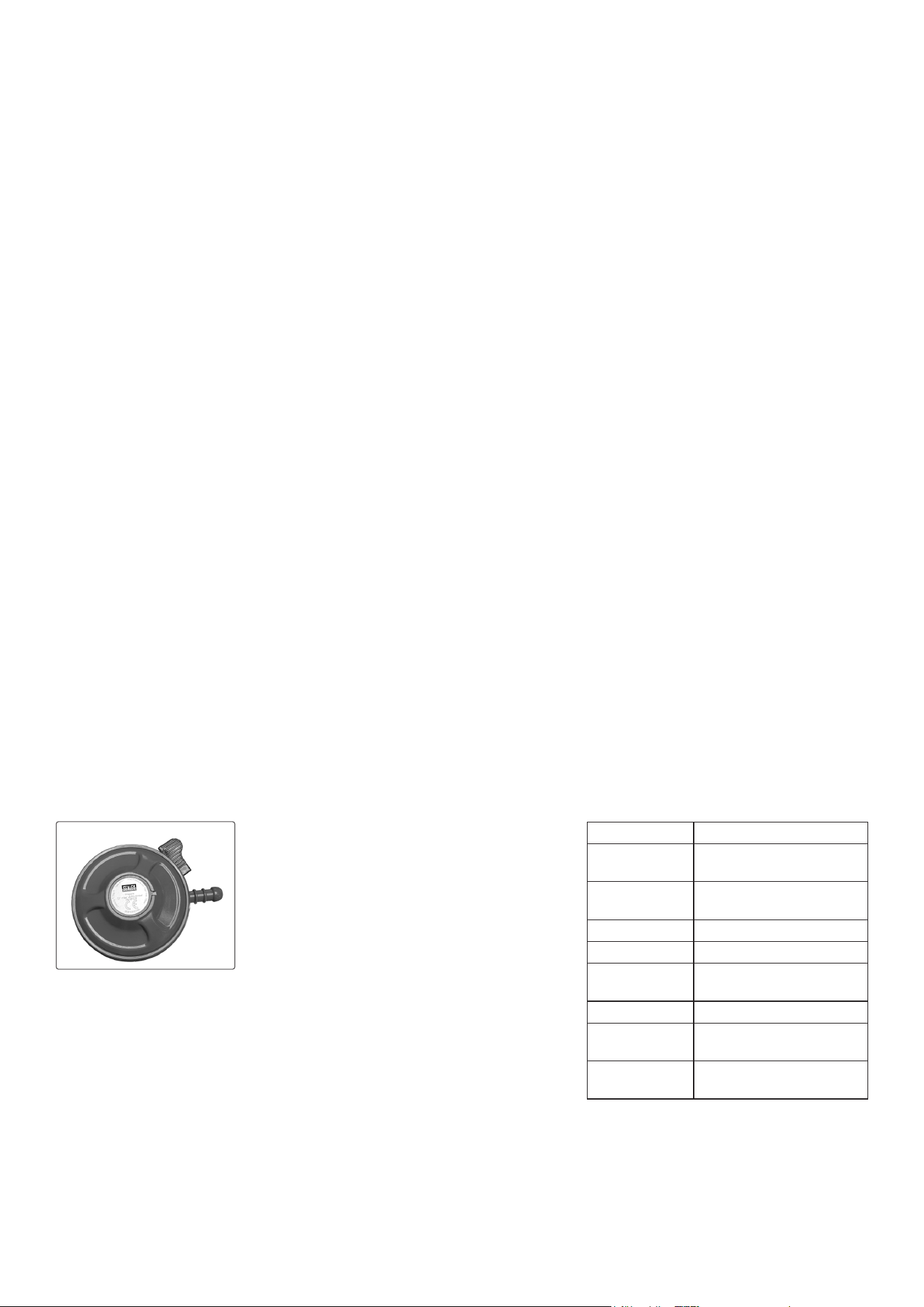
Regulator And Hose
• Only use regulators and hose approved for LPG stated on rating plate. The life expectancy of the regulator is estimated as 10 years. It is
recommended that the regulator is changed within 10 years of the date of manufacture.
• This product is supplied with a propane regulator and hose assembly.
• The use of the wrong regulator or hose is unsafe; always check that you have the correct items before operating the appliance.
• The hose used must conform to the relevant standard for the country of use. The length of the hose must be 1.5 meters (maximum). Worn or
damaged hose must be replaced. Ensure that the hose is not obstructed, kinked, or in contact with any part of the appliance other than at its
connection. Change the hose when the national conditions require it.
• The hose should not be twisted or kinked when attached to the regulator and appliance.
• No part of the hose should touch any part of the appliance. Site the cylinder out to the left hand side of the appliance at the maximum distance
permitted by the hose length.
• Make sure the vent on a regulator does not point upwards or is installed in a position allowing the ingress of water, either by; rain, snow or any
trickling or pooling. (If applicable).
• Protect from sea water spray unless the regulator is otherwise designed for this environment or is suitably protected.
• When the regulator (or change over device) is used outdoors, it shall be positioned or protected against penetration by any trickling water.
• Orientation of any diaphragm vent to avoid any water accumulation on the atmospheric side of the diaphragm. If applicable.
For your safety
• DO NOT force a regulator onto the cylinder valve if it does not t easily.
• DO NOT operate its mechanism using excessive force.
• DO NOT use regulators with US POL inlet ttings (designed for use on bulk storage vessels)
with Cylinder valves (the threads may look the same, but they are different).
• Never tamper with regulator.
• Never try to adjust non-user adjustable regulators, they are pre-set by the manufacturer to
control the gas supply at the correct pressure, unless you are qualied to do so.
• DO NOT purchase or use a second-hand regulator.
Gas Regulator IGT 27mm Push type
Regulator marked to BS EN 16129 standard
CE UK CA
Regulator cannot be tted unless in the off position.
Capacity 1.5kg/h Type.A127
Inlet pressure minimun 1 bar maximum.16 bar.
Propane 37mbar ∆ P2=2mbar.
The downstream installation pressure loss shall not
exceed the ΔP value marked on the device.
GAS TYPE: Propane
Inlet Pressure
(bar)
1 to 16
Normal Outlet
Pressure (mbar)
37
∆P2 (mbar) 2
∆P5 (mbar)
N/A
Working
temperature
-20°C to 50°C
Capacity 1.5Kg/h
Inlet connection G52-20mm, G53-21mm,
G54-22mm, G59-27mm, G61
Outlet
connection
H50, H51, H53
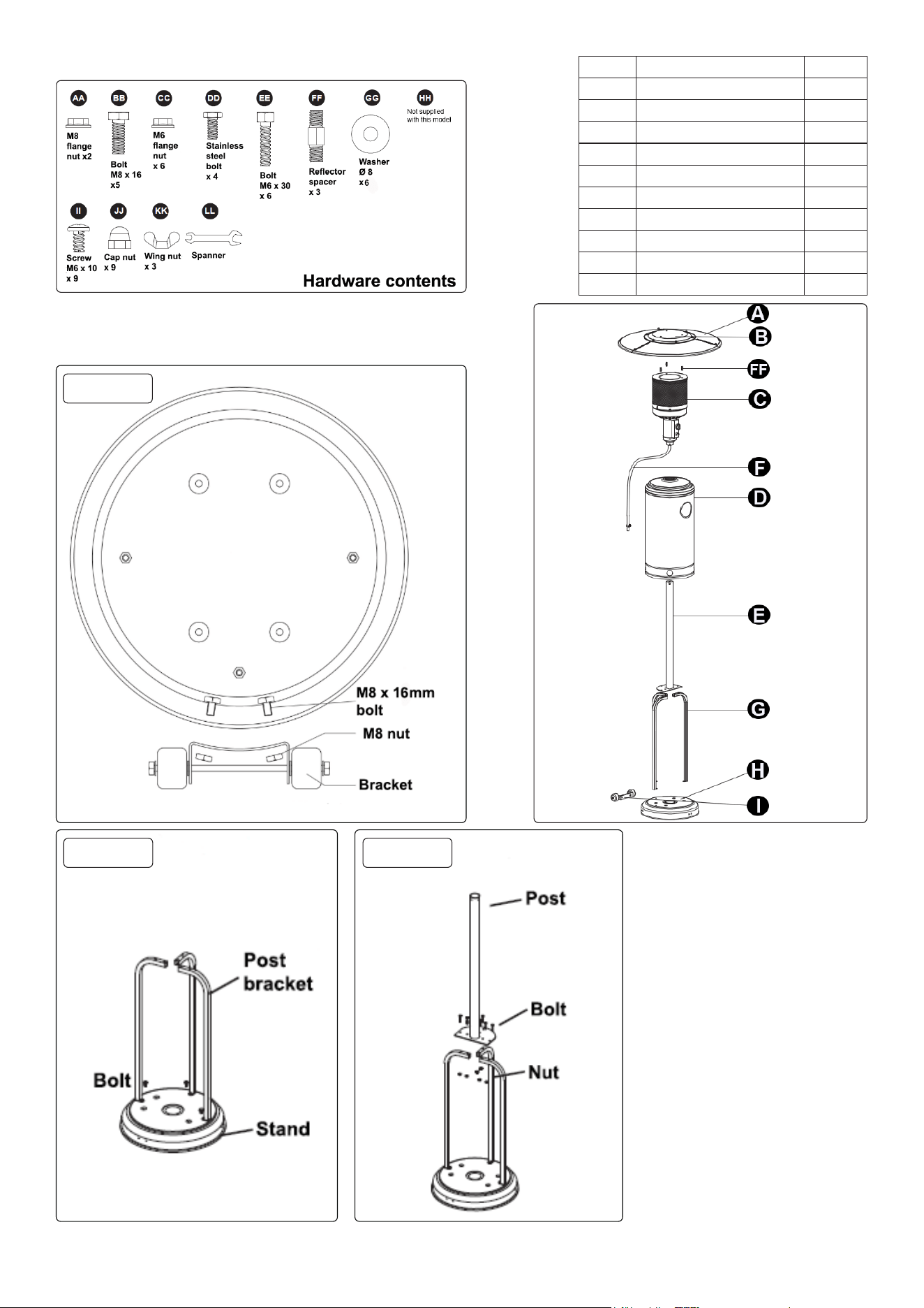
Contents
Assembly
• STEP 1
• Fix wheel bracket to base.
• STEP 2
• Fix the 3 post brackets as shown. Use bolt BB to join post brackets to the stand.
Step 1
Step 2 Step 3
PART DESCRIPTION QTY
A Reector outer 3
B Reector inner 1
C Burner head assembly 1
D Cylinder housing 1
E Main pole 1
F Gas hose 1
FF Reector spacer 3
G Support leg 3
H Base 1
I Wheel kit 1
• STEP 3
• Fix the post to the 3 post brackets. Use bolts EE and nuts CC. Tighten nuts and bolts.
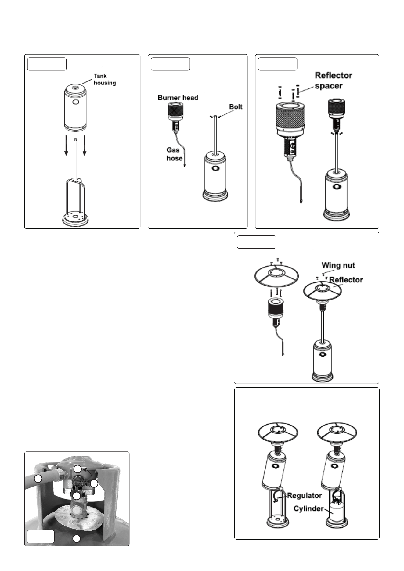
• STEP 4
• Place the tank housing over the post.
• STEP 5
• Remove four bolts from the base of the burner.
• Pass the gas hose down through the post.
• Fix the burner to the post, use bolt DD. Tighten nuts and bolts.
• STEP 6
• Place large washers GG on the 3 reector spacers FF.
• STEP 7
• Fix the reector onto the reector spacers use 3 x wing nut KK.
• STEP 8
• Raise the tank housing and rest it on the post plate. Be aware that it may fall if it is
knocked.
• Connect the gas hose to the regulator.
• Place the LPG cylinder on the stand.
Operation
• CONNECT GAS CYLINDER
• Change the gas cylinder in a amply ventilated area, away from
any ignition source (candle, cigarettes, other ame producing appliances).
• Lift the tank housing and prop it up on the top of the post brackets.
NOTE: In this instance the housing can not be propped up on the top of the post
brackets. A second person will be required to hold the tank housing up while the
gas cylinder is tted.
• Check the regulator seal. If damaged replace regulator.
• Use propane only.
• Only use hose and regulator supplied with heater.
• Never use a gas cylinder with a damaged valve or a damaged cylinder.
• Never connect an unregulated cylinder to the heater.
• GAS LEAKAGE
• In the event of gas leakage DO NOT use the heater. The gas supply should be shut
off and the cause should be investigated before it is used again.
Step 4 Step 5 Step 6
Step 7
1
3
2
1. Regulator ON position.
2. Regulator OFF position.
3. Regulator release button.
4. Gas cylinder.
5. Gas hose.
When attaching and detaching
regulator make sure the regulator
gas tap is in the OFF position.
4
5
fig.2
• LEAKAGE TEST
• WARNING! Never perform leak test near sources of ignition.
• Gas connections are tested at the factory. A complete gas tightness check must be completed at the installation site prior to use.
• Make a solution of one part liquid detergent and one part water. The soap solution can be applied with spray bottle, brush or rag. Soap
bubbles will appear at the site of a leak.
• Test must be performed with a full cylinder.
• Make sure the safety control valve is in the off position. Turn the gas supply on. In the case of a leak turn the gas supply off, re-tighten any ttings,
then turn the gas supply on and re-check.
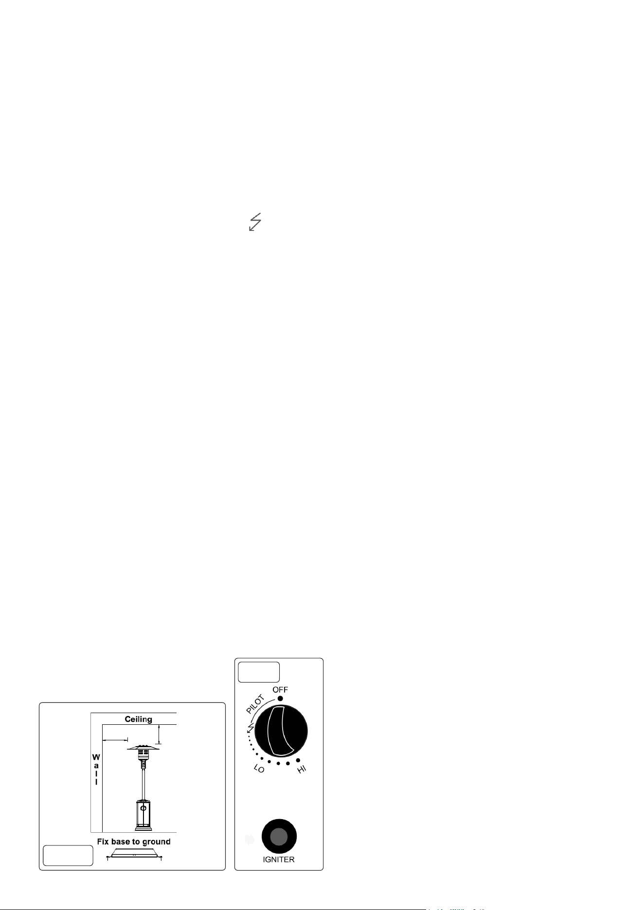
• LOCATION OF HEATER refer to g.3
• DANGER The use of this heater in enclosed areas is dangerous and is prohibited.
• Ensure that adequate fresh air ventilation is provided.
• Always maintain proper clearance from combustible materials, i.e top 1000mm and sides 1000mm minimum.
• Place on level solid ground.
• Never operate in an explosive atmosphere for example where explosive or ammable substances are stored.
• Protect from strong wind. Anchor securely to the ground with screws, refer to g.3A.
• TO TURN ON THE HEATER refer to g.4
• Turn cylinder valve fully on.
• Press in and turn the variable control knob to PILOT position (counter clockwise 90°).
• Press down the variable control knob and hold in for 90 seconds. Whilst holding down the variable control knob, press the igniter button several
times until the pilot ame lights. Variable control knob can be released after the pilot ame lights.
NOTE:
- If a new gas bottle has been connected, allow at least one minute for the air in the gas pipeline to purge out through the pilot hole.
- When lighting the pilot ame make sure the variable control knob is continuously pressed down, whilst pressing the igniter button.
- Variable control knob can be released after the pilot ame ignites.
- Pilot ame can be watched and checked from the small round window with the sliding lid, located at the bottom of the ame screen (to the left
or right side of the controller).
- If the pilot ame does not light or goes out repeat above paragraph.
• After the pilot ame lights, turn the variable ame knob to maximum position and leave it there for 5 minutes or more before turning the knob to
the desired position.
• TO TURN OFF THE HEATER
• Turn the variable control knob to the pilot position.
• Push knob in and move knob to off position.
• Turn off valve on cylinder completely.
• CHECK HEATER IMMEDIATELY IF:
- heater does not reach temperature,
- burner makes a popping noise during use (a slight noise is usual when the burner is extinguished).
- smell of gas in conjunction with extreme yellow tip of burner ame.
Storage
• Always turn off the gas valve on the gas cylinder after use.
• Disconnect the valve from the cylinder.
• Check the tightness of the gas valve. Check gas valve for damage.
• If damage is suspected have it inspected/changed by a gas stockist.
• DO NOT store a liquid gas cylinder in a cellar or in places without adequate air ventilation.
Maintenance
• REGULATOR AND HOSE
• The use of wrong regulator or hose is unsafe, always check that you have the correct items before using the heater.
• The hose must conform to the relevant standard for the country of use. The length of hose must be 1.5 meters (maximum). Worn or damaged
hose must be replaced. Ensure that the hose is not obstructed, kinked or in contact with any part of the heater other than its connection. Change
the hose when national conditions require it.
• Check the hose at least once a month, each time the cylinder is changed, or after a period when the heater has not been used.
• If it shows signs of cracking, splitting or other deterioration it must be changed for a new hose of equivalent length and quality.
• CLEANING
• Wipe surfaces with a soft, moist rag. DO NOT use combustible or corrosive cleaners.
• Remove debris from the burner to keep it safe for use.
• Cover the burner unit with the optional
protective cover (Model no. DG179) when not
in use.
fig.
4
fig.
3A
1000mm 1000mm
Dellonda Limited, Sole UK Distributor of Baridi
Kempson Way, Suffolk Business Park, Bury St Edmunds, Suffolk. IP32 7AR
01284 757575 suppor[email protected] www.dellonda.co.uk
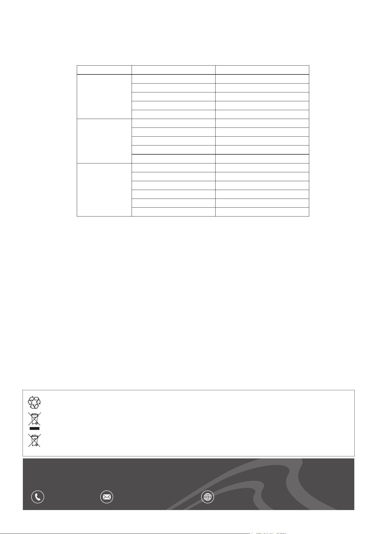
Environment Protection, Waste Electrical and Waste Electronic Equipment Regulations
(WEEE)
Recycle unwanted packaging materials. When this product is no longer required, or has reached the end of its useful life, please dispose
of in an environmentally friendly way. Drain any uids (if applicable) into approved containers, in accordance with local waste regulations.
Please note that this product contains one or more batteries. It is our policy to continually improve products and we reserve the right to
alter data, specications and parts without prior notice. No liability is accepted for incorrect use of this product. Guarantee is 12 months
from purchase date, proof of which is required for any claim.
Servicing
• Your gas appliance should be serviced annually by a competent registered person. Or contact Dellonda service centre on the contact details
below.
Troubleshooting
PROBLEM CAUSE SOLUTION
Pilot will not light Gas valve OFF Turn gas valve on
Gas cylinder empty Renew cylinder
Opening blocked Clean or replace opening
Air in supply system Purge air from lines
Loose connections Tighten connections
Pilot will not stay on
Debris around pilot Clean dirty area
Loose connections Tighten connections
Thermocouple faulty Replace thermocouple
Gas leak in the line Check connections
Lack of fuel pressure Cylinder nearly empty. Renew cylinder
Burner will not light
Pressure is low Cylinder nearly empty. Renew cylinder
Opening blocked Remove and clean
Control not ON Turn valve to ON
Thermocouple faulty Replace thermocouple
Pilot light assembly bent Reposition pilot light
Not in correct location (too windy) Position properly and retry