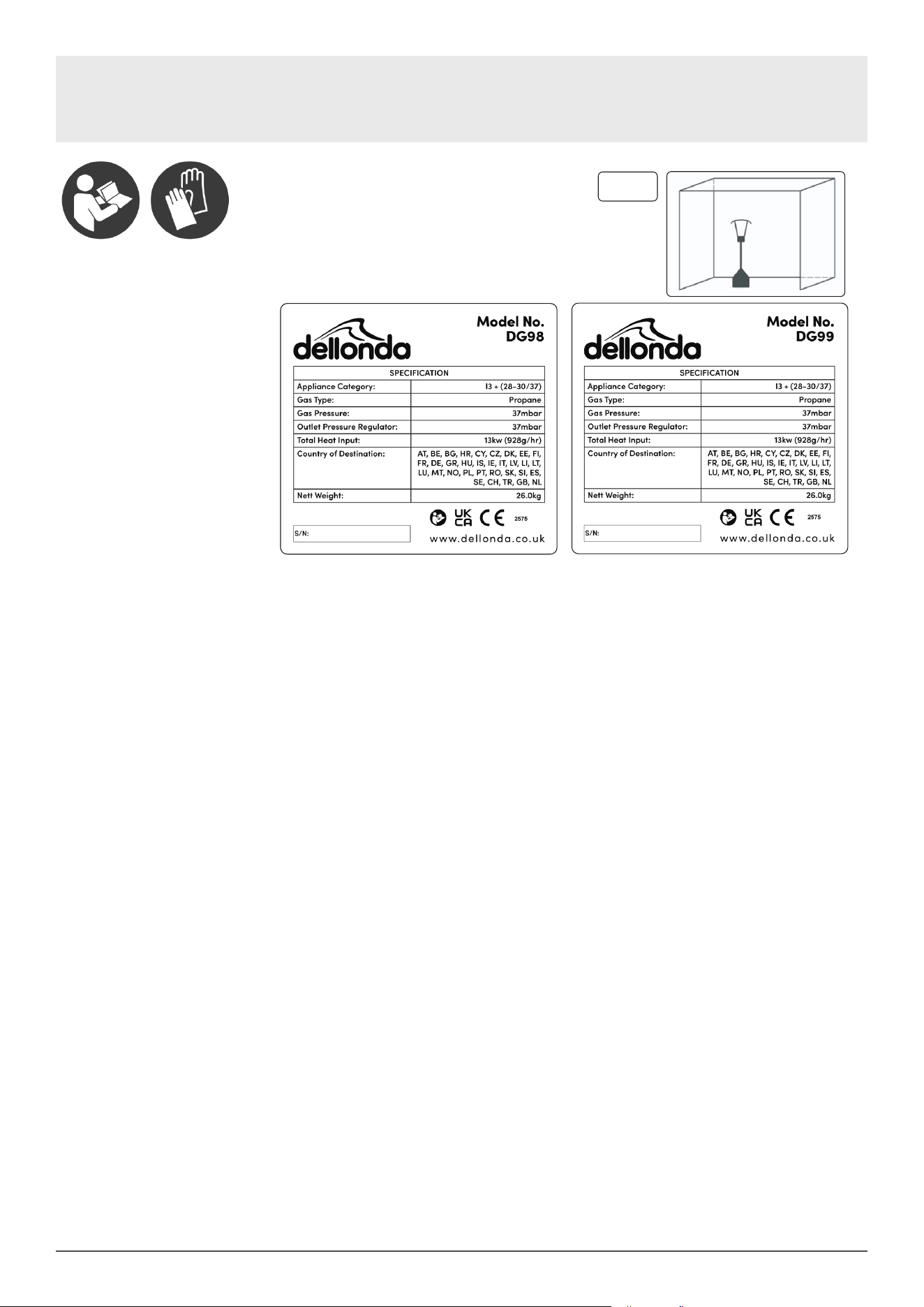
Model No. DG98, DG99
Thank you for purchasing a Dellonda product. Manufactured to a high standard, this product will,
if used according to these instructions, and properly maintained, give you years of trouble free performance.
www.dellonda.co.uk
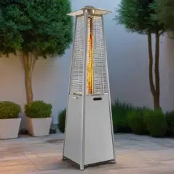
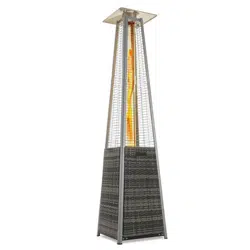
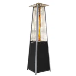
Dellonda Freestanding Gas Pyramid Patio Heater Outdoor
Garden Glass Tube 13kW
DG98 DG99 Issue:4 18/10/2024
2
Important Information
Please read these instructions carefully. Note the safe operational requirements, warnings & cautions. Use the product correctly and with care
for the purpose for which it is intended. Failure to do so may cause damage and/or personal injury and will invalidate the warranty. Keep these
instructions safe for future use.
Refer to
instruction
manual
Wear
Gloves
Specication label
About the Product
Innovative design of Gas Flame Pyramid Patio Heaters. These contemporary freestanding patio heaters produce a pleasant, heated working/
relaxing environment and are ideal for both commercial and domestic settings including open workshops, boat yards, patios, forecourts, gardens
and terraces. Standing at 2.27m tall, when lit the heaters produce a real ame encompassed by a glass tube which heats the surrounding area,
a metal reector makes sure heat is directed downwards and outwards. The units feature variable heat output controls and a fully enclosed gas
cylinder chamber with safety tip-over switch. Available in black or stainless steel and supplied with regulator and hose assembly for use with
propane patio gas bottles. These products should only be used in a well ventilated area.
Specication
Model ............................................................................DG98 .............................................................................................. DG99
Fuel Consumption: ..................................................... 945g/hr ........................................................................................... 945g/hr
Fuel: ......................................................................... Propane ......................................................................................... Propane
Heated Area: .................................................................... 8m² ................................................................................................. 8m²
Output: .......................................................................... 13kW .............................................................................................. 13kW
Product Dimensions (W x H): ..........................520 x 2270mm ................................................................................520 x 2270mm
Maximum Gas Bottle Size (W x H): ................ Ø320 x 700mm ...............................................................................Ø320 x 700mm
Safety Instructions
• Read the installation, operating and maintenance instructions thoroughly before installing or using this equipment.
• If there is a smell of gas: shut off the gas to the appliance, extinguish any open ames. If odour continues contact gas supplier.
• DO NOT store or use petrol or other ammable substances inside the housing of the heater.
• DO NOT store or use petrol or other ammable liquids or gases in the vicinity of the heater.
• DO NOT store a gas cylinder that is not connected for use in the vicinity of this or any other appliance.
• WARNING! DO NOT use indoors. For use outdoors or in amply ventilated areas.
• An amply ventilated area is one that has a minimum of 25% of the surface area open, see g.1. (The surface area is the sum of the wall surface.)
• WARNING! Not intended to be installed in recreational vehicles and/or boats.
• WARNING! Improper installation, adjustment, alteration, service or maintenance can cause injury or property damage.
• Installation and repair must be carried out by a qualied person.
• DO NOT attempt to alter in any way.
• This product must be installed and the gas cylinder stored in accordance with the local regulations in force.
• DO NOT obstruct the ventilation holes of the cylinder housing.
• DO NOT move/transport the appliance when in operation. Shut off the gas cylinder at the regulator before moving.
• DO NOT move/transport the heater until it has cooled down.
• Use only the type of gas and the type of cylinder specied by the manufacturer.
• The LP cylinder used with the patio heater must meet the following size requirements: Diameter 31.8cm x height 58cm, 15kg maximum capacity.
• In case of violent wind precautions must be taken against tilting of the appliance.
• Only use on level ground, capable of supporting the weight of the heater and the gas cylinder.
• DO NOT connect the gas cylinder directly to the appliance without a regulator. Use only the type of gas specied in the instructions.
• The whole gas system (hose, regulator, pilot or burner) should be inspected for leaks or damage before use and at least annually, by a suitably
qualied person.
• All leak testing should be done with an appropriate gas leak detection/soap solution. Never use an open ame to check for leaks.
• DO NOT use the heater until all connections have been leak tested.
fig.
1
3
• Turn off the gas immediately if a gas smell is detected. Turn cylinder valve OFF. If the leak is at the hose/regulator connection tighten the
connection and perform another leak test. If bubbles continue appearing contact your supplier. If the leak is at the regulator/cylinder connection
disconnect from cylinder, reconnect and perform another leak check. If soap bubbles are still seen, cylinder valve is defective. Return cylinder to
its place of purchase.
• Keep the ventilation opening of the cylinder enclosure free and clear of debris.
• DO NOT paint the radiant screen, control panel or top canopy reector.
• Control compartment, burner and circulation air passageways of the heater must be kept clean.
• Turn off gas whilst not in use.
• LP regulator/hose assembly must be a protected from accidental damage.
• Any guard removed for servicing/maintenance must be replaced before operation.
• Keeps adults and children away from the high temperature surfaces, to avoid burns and ignition of clothing.
• Children should be carefully supervised when they are in the vicinity of the heater.
• DO NOT hang clothing or other ammable materials on the heater or place them near the heater.
Heater Stand and Location
• The heater is primarily for outdoor use only. Always ensure that adequate fresh air ventilation is provided.
• Always maintain proper clearance to non protected combustible materials i.e. top 100 cm and sides 100 cm minimum.
• Heater must be placed on level rm ground.
• Never operate heater in an explosive atmosphere like in areas where gasoline or other ammable liquids or vapours are stored.
• To protect heater from strong wind, anchor the base securely to the ground with screws.
• Gas Requirements
• This heater is primarily designed to be used with propane gas.
• Butane gas may also be used with the appropriate regulator however butane freezes at zero degrees so will not be ideal to be used during cold
temperatures.
• A dented, rusted or damaged cylinder may be hazardous and should be checked by your gas supplier before being used with this heater.
• Never connect an unregulated cylinder to the heater.
Contents
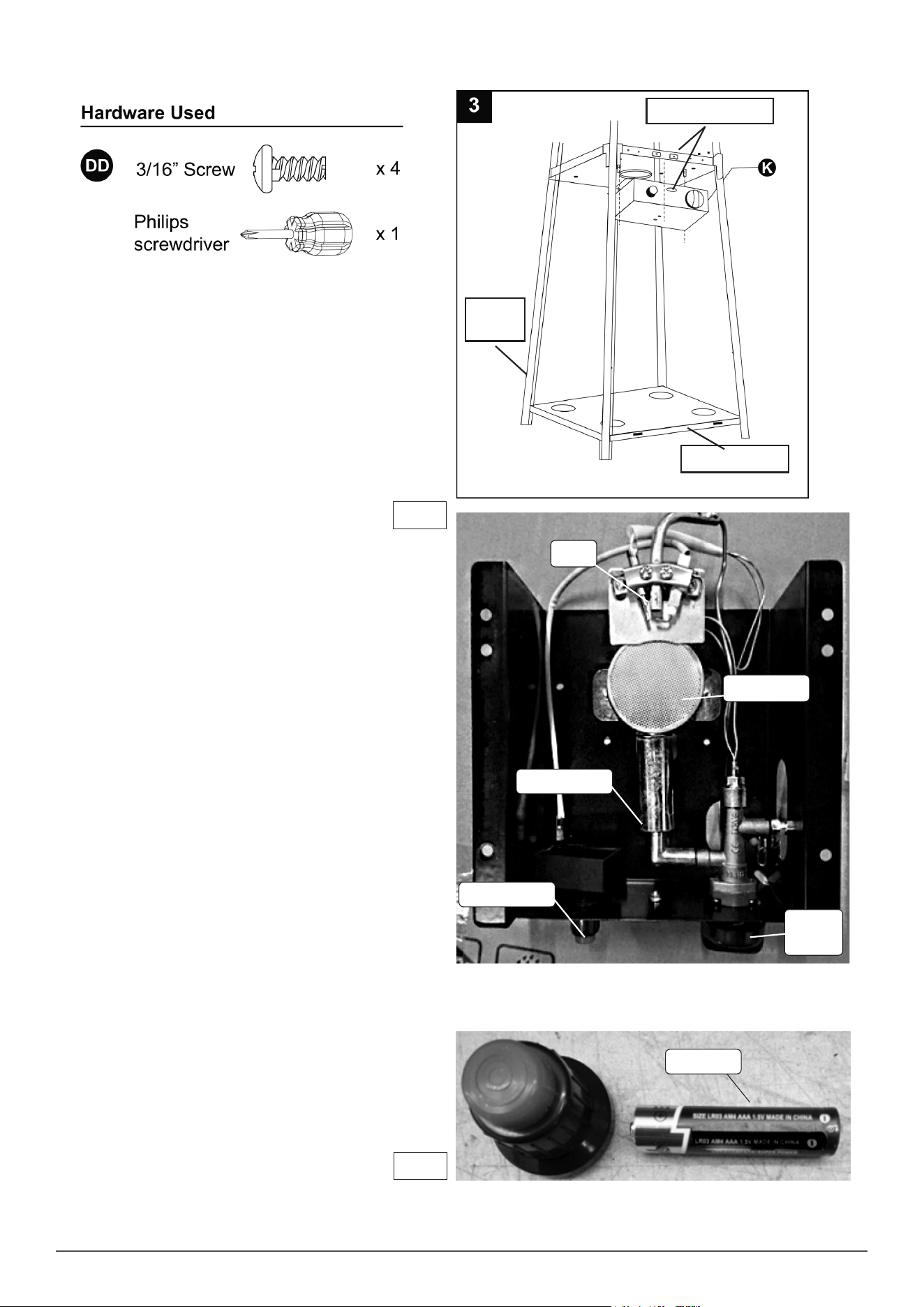
• 1. Assemble the wheel assembly (M) to the bottom plate (N). Fix the wheel assembly (M) to the bottom plate (N) using 4pcs bolt M8x12 (EE) and
(Model No. DG10001; 37mbar)
4
Assembly
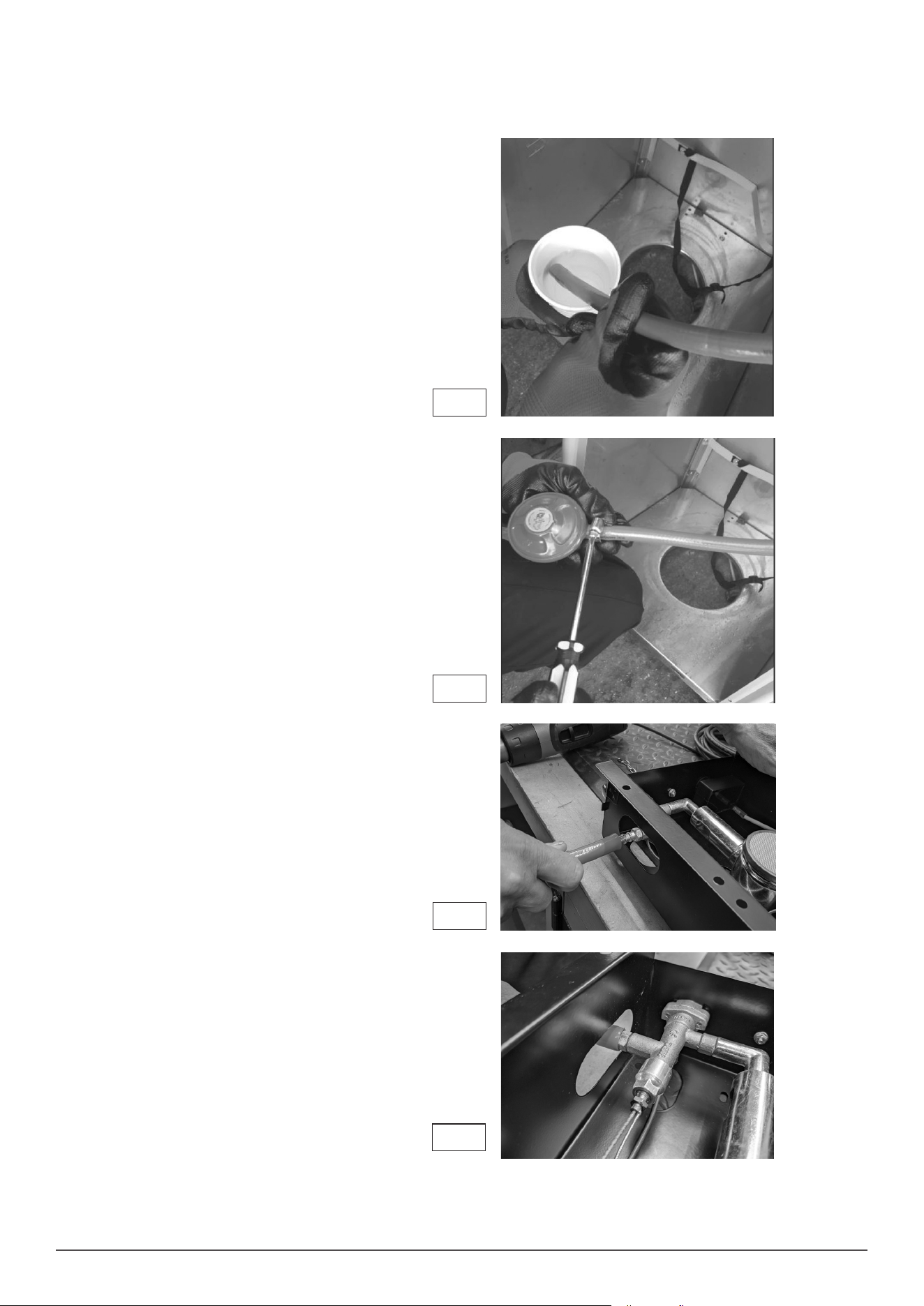
• It is recommended that you connect the gas regulator hose to the regulator and the control unit (K) prior to assembling the unit, be careful not to
damage or dislodge components in the control unit (K).
To assist connecting the regulator, carefully place the rubber
hose into an insulated cup of boiling hot water (Fig.1). This
allows the rubber hose to expand, ensure the hose clip is
slid over the hose and then push the open hose end fully
onto the gas regulator inlet.
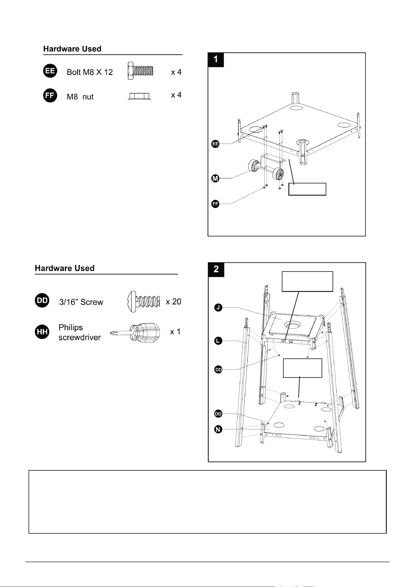
After connecting the regulator, slide the hose clip back to
near the end of the hose and tighten with a screwdriver
(Fig.2).
NOTE: Ensure you leak test this joint as directed on Page 9
after assembly is complete and when you rst connect the
gas bottle.
Fig. 1
Fig. 2
Now connect the open hose end to the control unit (K) again
carefully place the rubber hose end into an insulated cup
of boiling hot water (Fig.1). This allows the rubber hose
to expand, ensure the hose clip is slid over the hose and
then push the open hose end fully onto the gas inlet on the
control unit as shown in Fig. 3.
Fig. 3
Fig. 4
After connecting the hose into the control unit (K) slide the
hose clip back to near the end of the hose and tighten with a
screwdriver (Fig.2).
NOTE: Ensure you leak test this joint as directed on Page 9
after assembly is complete and when you rst connect the
gas bottle.
5
4pcs ange nut M8 (FF).
2. Insert the pins of the bottom plate (N) to the holes of lower support (L), press to secure the pins. Using 12pcs screw 3/16” (DD) to secure the
lower support (L) and bottom plate (N). Using 8pcs screw 3/16” (DD) to secure the lower support (L) and middle plate (J).
Back of unit
NOTE:
It is vital at this stage to ensure that the bottom plate (N) and the middle plate (J) are assembled correctly. The
wheels on the bottom plate (N) are the back of the unit and the magnetic catches on the middle plate (J) for
the door are on the front of the unit, these parts must be on OPPOSITE sides of the unit. This must be correct
at this stage to ensure the unit operates correctly.
Magnetic catches,
front of the unit.
Wheels, back
of the unit.
6
3. Fix the Control Box Assembly (K) to the Middle Plate (J) using 4pcs screw 3/16’ (DD)’.
• Additional Note : Unscrew the red ignition button and insert an AAA Battery (Fig. 6) not supplied.
• Note: Once the lower section is assembled you should be able to see the gas burner mesh gauze sitting in the centre of the
hole in the middle plate (J) if not *STOP* and re-trace your steps to ensure the assembly is progressing correctly.
Back of
the unit.
Front of the unit.
Controls facing front
Fig. 5
• The ignition switch must have a AAA battery
inserted into it, Unscrew the collar of the switch
and insert a battery then re screw the switch head
into place (Fig.6).
Fig. 6
Igniter
Ignition switch
Control
knob
Burner Mesh
Mixing chamber
AAA Battery
7
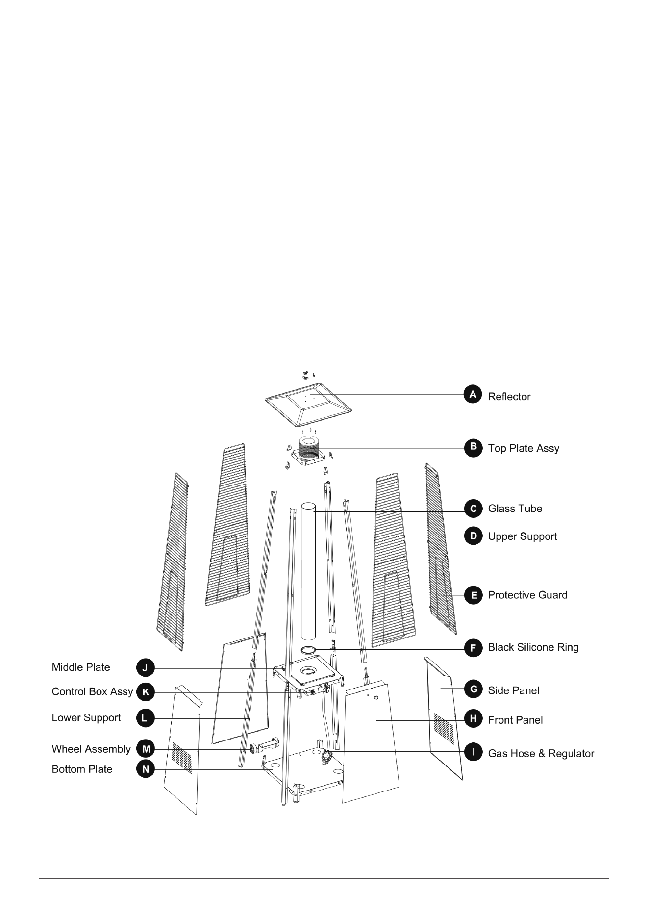
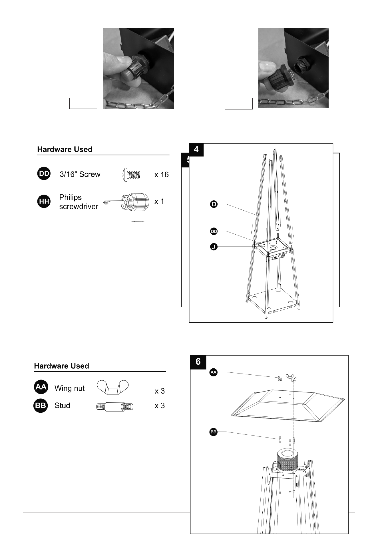
• 4. Assemble the upper supports (D). Insert the 4pcs of upper support (D) to the middle plate (J). Secure them with 16pcs screw 3/16” (DD)
• 5. Assemble the top plate assy (B) to the upper supports (D).Secure the top plate assy (B) to the upper supports (D) using 8pcs screw 3/16” (DD)
• 6. Assemble the reector (A) onto the top plate assy (B). Screw the 3 studs (BB) on the top plate assy (B), then put the reector (A) onto the studs
(BB), secure them with 3pcs wing nuts (AA).
• Unscrew the button collar
until it comes away from
the unit. (Fig. 6.1).
• Slide in a AAA battery
and re-screw the button
into position. (Fig. 6.2).
Fig. 6.1
Fig. 6.2
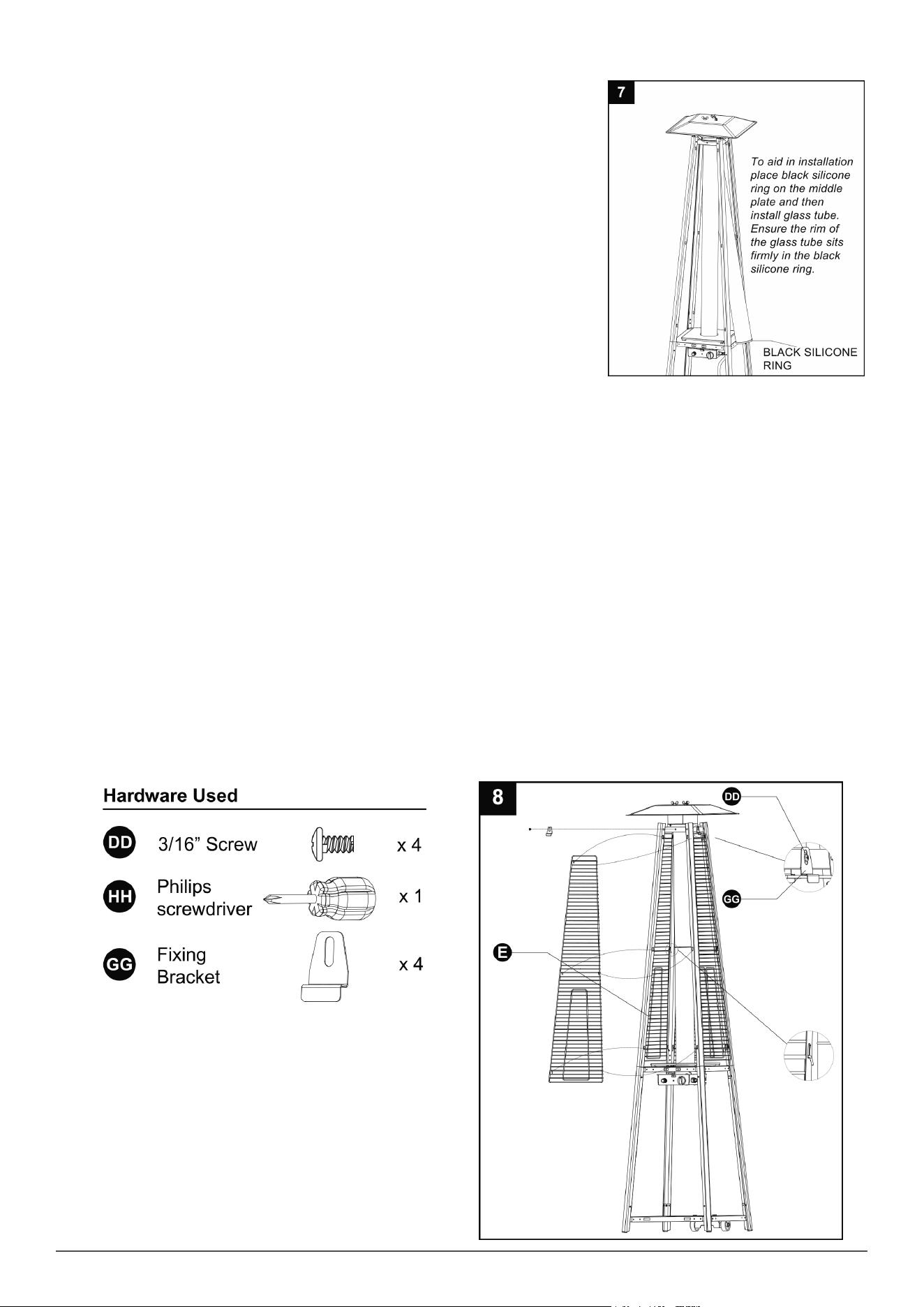
8
• 7. Carefully install the glass tube (C) by lifting up and inserting through the centre hole in the top
plate (B). Ensure the black silicone ring (F) is attached to the lower edge of the glass tube (C) as
illustrated. Slide the glass tube (C) through the hole of the lower plate cover and onto the middle
plate (J). Check and ensure that the glass tube (C) is positioned properly and is completely
covering the centre hole of the middle plate(J).
• WARNING! The black silicone ring must be in place prior to operating the heater.
• 8. Assemble the protective guard (E). Line up the hooks on the protective guard (E) into the holes in supports. Secure the protective guards (E)
with xing brackets (GG) using 4pcs 3/16” screws (DD).
9
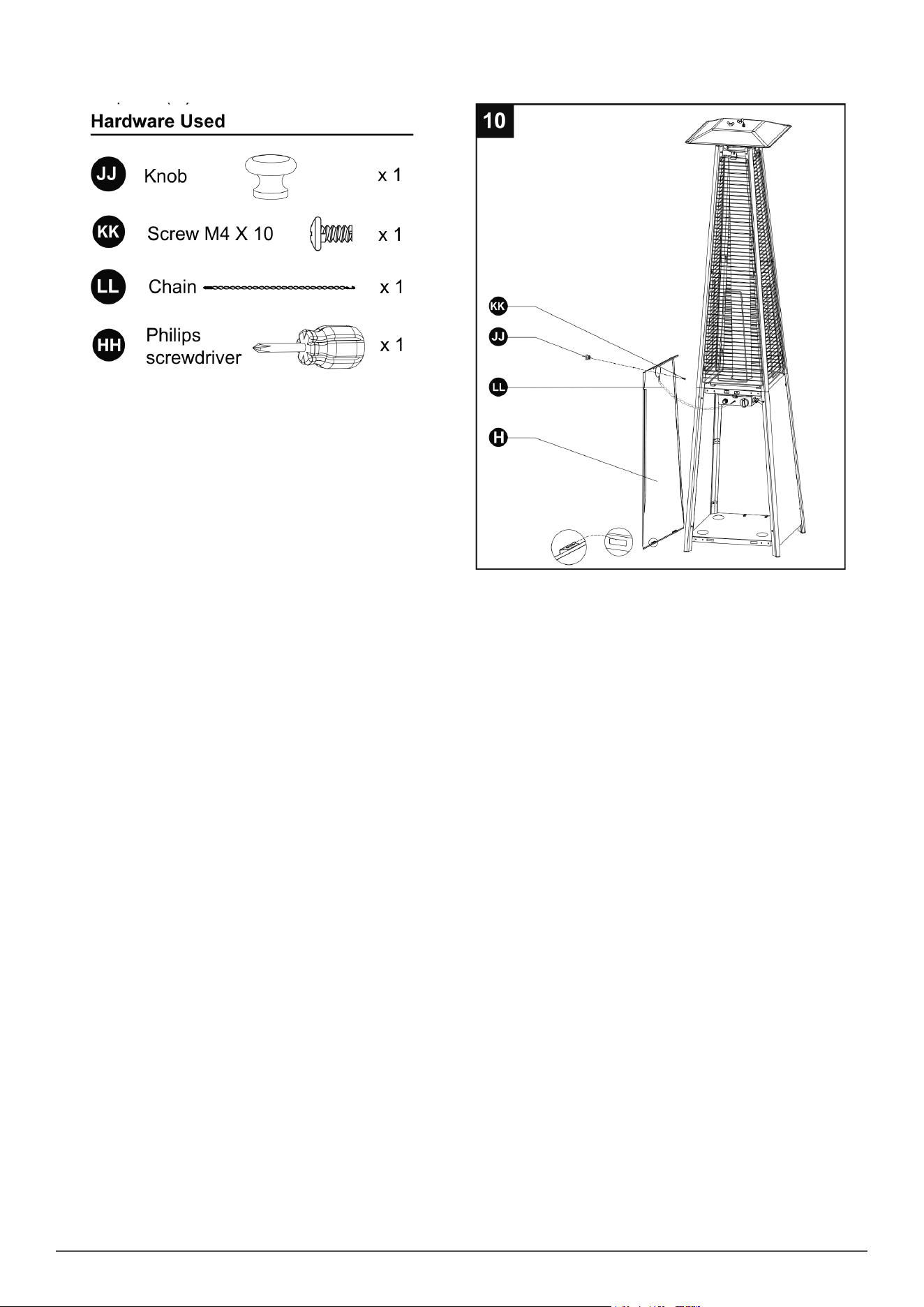
• 9. Attach the three side panels (G) to the heater using 12pcs screw 3/16” (DD) Note: Do not cover the front side where the control knob is.
• 10. Install the knob to M4x 10 screw (KK). Hang the chain (LL) to the hole on the control box assy (K) and put the pothook of front panel (H) to the
holes of bottom plate (N).
Leak Test
• Gas hose connections on the heater must be tested as well as the regulator connection to the gas bottle on completion of assembly and when
rst connected to the gas bottle.
• Leak testing: Do not smoke while performing this test, and remove all sources of ignition.
• A full gas cylinder is required. This test must be done before initial use, annually and whenever any gas Components are replaced or serviced.
• 1. Mix a solution of water and washing up liquid, then pour onto the connection between the joints and connections of the regulator, hose,
manifolds and valves. Turn all burner controls to the off position. Turn the gas regulator ON.
• If no bubbles are present - This indicates the connection is leak safe.
• If bubbles are present - Tighten the hose clip further and retest for leaks
• If bubbles continue to appear - please contact your gas supplier or heater distributor
• 2. If the leak cannot be stopped, immediately shut off the gas supply and disconnect it.
• 3. Do not use the patio heater until the leak has been corrected.
Regulator and Hose
• Only use regulators and hose approved for LPG at the above pressures. The life expectancy of the regulator is estimated as 10 years. It is
recommended that the regulator is changed within 10 years of the date of manufacture.
• The use of the wrong regulator or hose is unsafe; always check that you have the correct items before operating the heater.
• The hose used must conform to the relevant standard for the country of use. The length of the hose must be 1.5 meters (maximum).
OPERATION AND STORAGE
• TO TURN THE HEATER ON
• WARNING: Please ensure the glass tube has not been damaged before operation
• 1. Ensure the variable control knob is at the OFF position.
• 2. Connect the gas regulator to a compatible gas cylinder.
• 3. Push and turn the variable control knob to the “Pilot “ position and hold for 60 seconds. Whilst still holding the control knob down, press the
ignition button. A pilot ame should appear.
• 4. Once the blue pilot ame stays alight constantly, let go of the variable knob.
• 5. Turn the variable control knob to the desired temperature position -Lo to Hi.
• IMPORTANT NOTE When lighting the heater for the rst time or a new cylinder is connected, the air inside the hose must be purged. This process
will take a few minutes as liqueed petroleum gas is heavier than air.
• As a result the variable control knob should be pressed down at the Pilot position for 3 Minutes instead of the normal 60 second period.
• This ensures the gas purges the air in the hose and passes from the cylinder through to the main burner.
• TO TURN THE HEATER OFF
• 1. Turn the variable control to the PILOT position.
• 2. Push and turn the variable control knob to the OFF position.
• 3. Turn the regulator connected to the gas cylinder to the OFF position.
• STORAGE
• Always turn the regulator connected to gas cylinder OFF after use.
• Disconnect the regulator from the cylinder if the heater is not in use.
• Never store the gas cylinder indoors or without adequate air ventilation.
Maintenance
• CLEANING AND CARE
• Wipe off surfaces with soft, moist cloth. Do not clean the heater with cleaning products that are combustible or corrosive.
• Remove debris and insects from the burner periodically to keep it clean and safe for use.
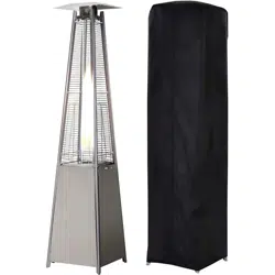
• Cover the burner unit with the optional protective cover when the heater is not in use.
Dellonda Limited
Kempson Way, Suffolk Business Park, Bury St Edmunds, Suffolk. IP32 7AR
01284 757575 suppor[email protected] www.dellonda.co.uk
Environment Protection and Waste Protection and Electrical Equipment Regulations (WEEE)
Recycle unwanted packaging materials. When this product is no longer required, or has reached the end of it’s useful life, please dispose of
it in an environmentally friendly way. Drain any fluids (if applicable) into approved containers, in accordance with local waste regulations.
It is our policy to continually improve products and we reserve the right to alter data, specifications and parts without prior notice. No
liability is accepted for incorrect use of this product. Guarantee is 12 months from purchase date, proof of which is required for any claim.
Problem Probable Cause Suggested Solution
Pilot will not light Gas regulator may be OFF
Gas cylinder empty Opening blocked Air in supply
system Loose connections
Turn the regulator ON Replace with full cylinder Clean or
replace opening Purge air from lines Check all ttings
Pilot will not stay on Debris around pilot Loose connections Thermocouple
faulty
Anti tilt switch loose/faulty Gas leak in line
Lack of fuel pressure
Clean dirty area Tighten connections Replace
thermocouple
Reconnect/replace anti tilt switch Check connections
Tank near empty. Rell LPG tank.
Burner will not light Pressure is low Opening blocked Control not ON
Thermocouple faulty Pilot light assembly bent Not in
correct location
Cylinder is almost empty. Replace with full cylinder
Remove and clean Turn valve to ON Replace
thermocouple Place pilot properly
Position properly and retry
Troubleshooting