Ns0522-1122
Printed in China
• Before attempting to connect or install this product, please read these instructions carefully and
save this manual for future use.
• The external appearance and other parts shown in this manual may differ from the actual product
within the scope that will not interfere with normal use due to improvement of the product.
Do not use this bracket except with suitable cameras.
Failure to observe this may cause a drop resulting in injury or accidents.
Refer installation work to the dealer.
Installation work requires technique and experience.
Failure to observe this may cause fire, electric shock, injury, or damage to the product.
Be sure to consult the dealer.
Install the product securely on the bracket by following the installation
instructions.
Failure to observe this may cause injury or accidents.
Thescrewsandboltsmustbetightenedtothespeci�edtorque.
Failure to observe this may cause a drop resulting in injury or accidents.
The measures of protection against a fall of this product shall be taken.
Failure to observe this may cause a drop resulting in injury or accidents.
Be sure to install the safety wire.
Do not rub the edges of metal parts with your hand.
Failure to observe this may cause injury.
When using this product, also read the “Precautions” described in the operating
instructions for the camera to be attached.
Precautions
i-PRO Co., Ltd. assumes no responsibility for injuries or property damage resulting
from failures arising out of improper installation or operation inconsistent with this
documentation or through use of parts other than this product, such as locally
procured parts.
Caution:
• Before attempting to connect or operate this
product, please read these instructions care-
fully.
Notice:
• This product is not suitable for use in loca-
tions where children are likely to be present.
• Do not install this product in locations where
ordinary persons can easily reach.
• For information about screws and other parts
required for installation, refer to the corre-
sponding section of this document.
Mount Bracket
Model No. WV-QSR501
Operating Instructions
Included Installation Instructions
Other items that are needed (not included)
Common
• Screws to fix a locally procured bracket on the installation surface
• 5 mm (distance between two parallel sides of a hexagon) hex wrench
• Sealant for waterproof treatment
• Safety wire
• Safety wire fixing screw
• Use a screw having a pull-out strength that is enough to hold the sum of weight of the
camera, this bracket, locally procured bracket, wire and cables.
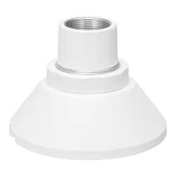
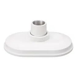
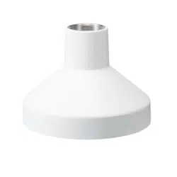
Preface
This product is a mount bracket for a camera. Use this product when connecting a camera to a
ceiling mount bracket, wall mount bracket or a locally procured bracket.
The latest information about the supported cameras
<Control No.: C0501>
The model number is abbreviated in some descriptions in this manual.
Specifications
In order to prevent injury, this product must be securely mounted to a bracket
according to Installation Guide.
Mounting method for this product
This product is designed to be used as a pendant mount camera. If it is mounted on a desktop or at
a slant, the camera may not work correctly and its lifetime may be shortened.
Installation place
Salt damage prevention is applied to this product. However, it is not completely anti-corrosive.
Therefore, consider a place for installation where direct splash of seawater can be avoided.
Especially when installing this product in a seashore area or a place where a snow-melting agent is
applied, and also where rainwater is avoided, it is recommended to regularly clean and rinse off salt
with water. In case of installing this product in a seashore area, regularly check the status of equipment.
(Replace the parts as required.)
Make sure to remove this product if it will no longer be used.
Precautions for installation
Standard Accessories
Operating Instructions (this document) ....................................................................................... 1 pc.
Inner cover ................................................................................................................................ 1 pc.
Screw A (Fixing screw for the inner cover: M3 x 8 mm {5/16 inches}) .......................................4 pcs.
(of them, 1 for spare)
Base guide plate*
1
..................................................................................................................... 1 pc.
Screw B*
1
(Fixing screw for the base guide plate: M4 x 8 mm {5/16 inches}) ............................5 pcs.
(of them, 1 for spare)
Screw C (Fixing screw for attachment plate: M4 x 8 mm {5/16 inches}) ....................................5 pcs.
(of them, 1 for spare)
*1 Base guide plate and screw B are not included in .
Ambient operating temperature: –50 °C to +60 °C {–58 °F to +140 °F}
Dimensions: Maximum diameter: ø176 mm {6-15/16 inches}
Height: 131 mm {5-5/32 inches}
(When base guide plate and other components installed:
Height 135.5 mm {5-11/32 inches})
Mass:
Main body: Approx. 480
g
{1.06 lbs}
Base guide plate and others: Approx. 140
g
{0.31 lbs}
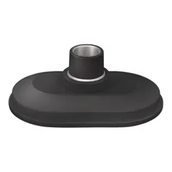
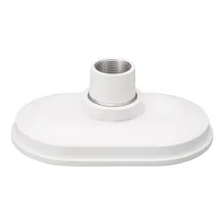
Finish:
Main body: Aluminum die cast,
i-PRO white/black
Heavy salt damage prevention coating, i-PRO white
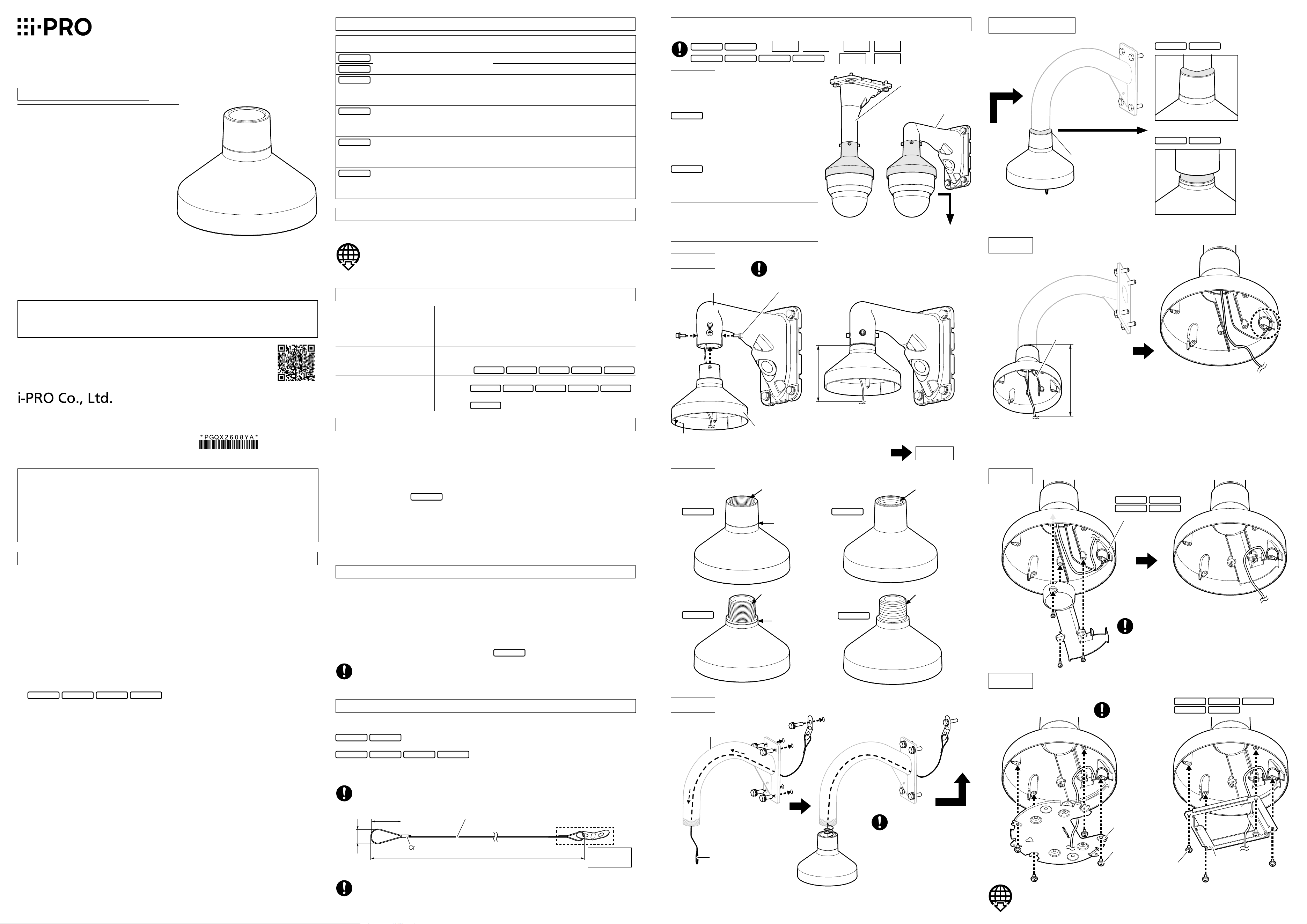
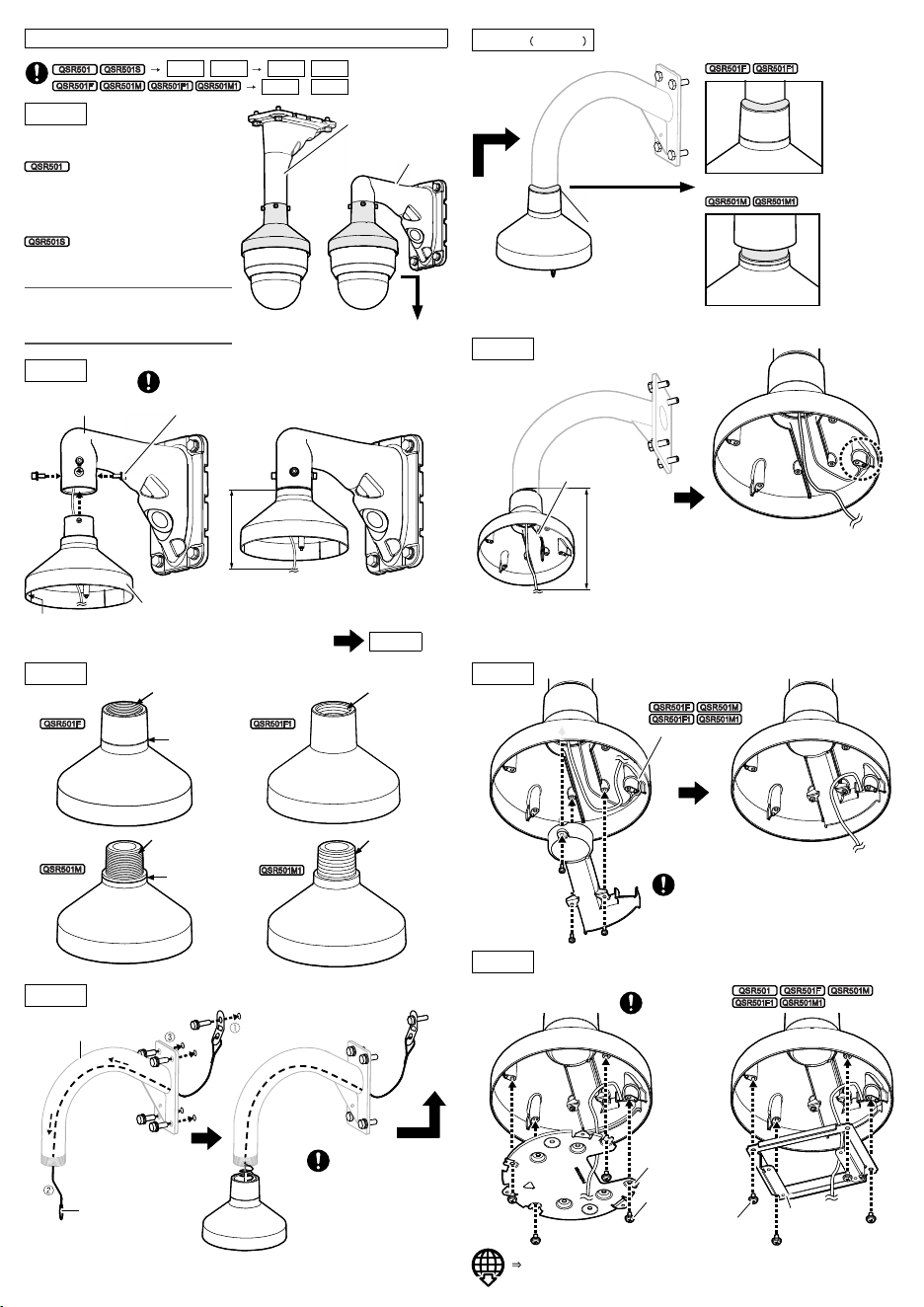
Installation
Check of combination of brackets
• Brackets with normal specification
+ WV-QCL501
(Ceiling mount bracket)
+ WV-QWL501
(Wall mount bracket)
• Brackets with heavy salt damage resistance
specification
+ WV-QCL501S
(Ceiling mount bracket)
+ WV-QWL501S
(Wall mount bracket)
Note:
• Refer to the operating instructions of each
bracket for how to fix the brackets to be used
with to the installation surface.
Waterproof treatment
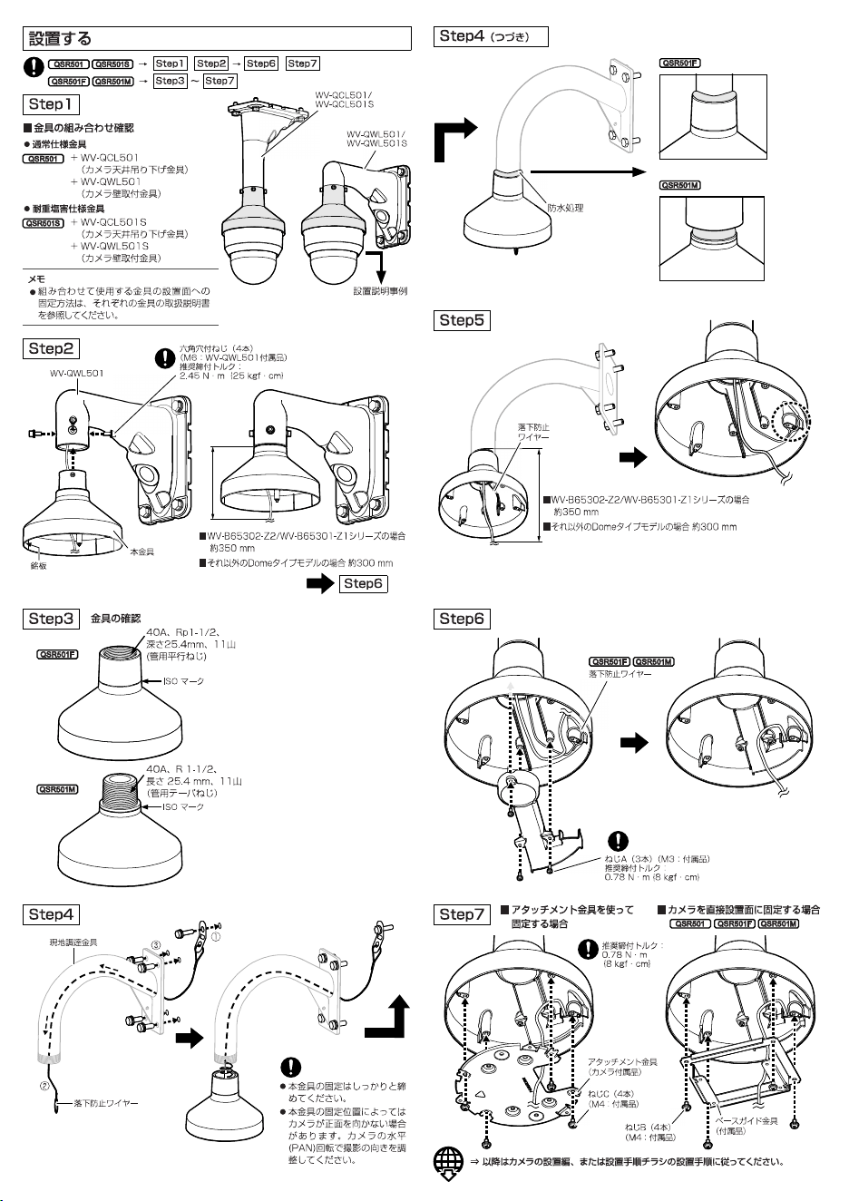
Step 1
Step 2
Step 5
Step 3
Step 4
Check of brackets
Step 4 Continued
Step 6
Step7
Hexagon screw (4 pcs.)
(M6: WV-QWL501 accessory)
Recommended tightening torque:
2.45 N·m {1.81 lbf·ft}
WV-QWL501
Example of explanation
for installation
Step3 Step7
• Select a fixing method in accordance with the installation place surface for a part where the
safety wire is to be fixed.
• Use the dedicated tool when processing the wire.
• Maximum weight of locally procured bracket: 5 kg {11 lbs}
• Use the base guide plate when fixing the camera by utilizing the installation dimension of
83.5 mm x 64 mm {3-9/32 inches x 2-17/32 inches}.
• When fixing the camera after installing this bracket, use the screw that is yet unused
among screw B and screw C.
WV-QCL501/
WV-QCL501S
WV-QWL501/
WV-QWL501S
Nameplate
Safety wire
Follow the installation procedure described in the installation guide or in the
installationprocedureleafletofthecameraforthesubsequentprocedures.
Safety wire
When�xingwiththe
attachment plate
When�xingthecameradirectly
onto the installation surface
Attachment plate
(camera accessory)
Screw C (4 pcs.)
(M4: accessory)
Base guide plate
(accessory)
Screw B (4 pcs.)
(M4: accessory)
Recommended
tightening torque:
0.78 N·m {0.58 lbf·ft}
For WV-U65302-Z2/WV-U65301-Z1 series
Approx. 350 mm {13-25/32 inches}
For dome type models other than the above
Approx. 300 mm {11-13/16 inches}
For WV-U65302-Z2/WV-U65301-Z1 series
Approx. 350 mm {13-25/32 inches}
For dome type models other than the above
Approx. 300 mm {11-13/16 inches}
Step6
• Securely fasten when fixing
this product.
• Depending on the fixing posi-
tion of this product, the cam-
era may not face the front.
Perform an adjustment of the
camera direction by panning
this product.
This bracket
Screw A (3 pcs.) (M3: accessory)
Recommended tightening torque:
0.78 N·m {0.58 lbf·ft}
WV-QSR501F-W
About notations
Connection part
specifications of this product
Mount bracket
corresponding with this product
4 holes
WV-QCL501, WV-QWL501
WV-QCL501S, WV-QWL501S
Female screw (ISO)
40A, Rp 1-1/2, 11crest
depth25.4mm{1inch}
(parallel thread)
Locally procured
40A, R 1-1/2, 11crest
length25.4mm{1inch}ormore
(
taper pipe thread
)
Female screw (ANSI)
40A, NPSC 1-1/2, 11.5 crest
depth25.4mm{1inch}
(parallel thread)
Locally procured
40A, NPT 1-1/2, 11.5 crest
length25.4mm{1inch}ormore
(taper pipe thread)
Male screw (ISO)
40A, R 1-1/2, 11 crest
length25.4mm{1inch}
(
taper pipe thread
)
Locally procured
40A, Rp 1-1/2, 11 crest
depth25.4mm{1inch}ormore
(parallel thread)
Male screw (ANSI)
40A, NPT 1-1/2, 11.5 crest
length25.4mm{1inch}
(
taper pipe thread
)
Locally procured
40A, NPSC 1-1/2, 11.5 crest
depth25.4mm{1inch}ormore
(parallel thread)
Wire specification: SUS ø1.5 mm {1/16 inches}, 7x7
Rupture strength: 1127 N {253 lbf} or higher
Inside dimension
34 mm {1-11/32 inches} or more
Crimping process
Inside
dimension
17 mm {21/32 inches}
or more
Installation
surface
Length: Distance to the wire hook on the camera through the
inside of the bracket + 50 mm {1-31/32 inches}
40A, Rp 1-1/2,
11 crest
depth 25.4 mm
{1 inch}
(parallel thread)
40A, NPT 1-1/2,
11.5 crest
length 25.4 mm
{1 inch}
(taper pipe thread)
40A, NPSC 1-1/2,
11.5 crest
depth 25.4 mm
{1 inch}
(parallel thread)
ISO mark
ISO mark
40A, R 1-1/2, 11 crest
length 25.4 mm
{1 inch}
(taper pipe thread)
“<Control No.: C****>” used in these documents should be used to search for information
on our technical information website (https://i-pro.com/global/en/surveillance/training-
support/support/technical-information) and will guide you to the right information.
Step1 Step2 Step6
https://www.i-pro.com/
© i-PRO Co., Ltd. 2022
Step7
–
Locally procured bracket
Safety wire (locally procured)
Ns0522-1122
Printed in China
• Before attempting to connect or install this product, please read these instructions carefully and
save this manual for future use.
• The external appearance and other parts shown in this manual may differ from the actual product
within the scope that will not interfere with normal use due to improvement of the product.
Do not use this bracket except with suitable cameras.
Failure to observe this may cause a drop resulting in injury or accidents.
Refer installation work to the dealer.
Installation work requires technique and experience.
Failure to observe this may cause fire, electric shock, injury, or damage to the product.
Be sure to consult the dealer.
Install the product securely on the bracket by following the installation
instructions.
Failure to observe this may cause injury or accidents.
Thescrewsandboltsmustbetightenedtothespeci�edtorque.
Failure to observe this may cause a drop resulting in injury or accidents.
The measures of protection against a fall of this product shall be taken.
Failure to observe this may cause a drop resulting in injury or accidents.
Be sure to install the safety wire.
Do not rub the edges of metal parts with your hand.
Failure to observe this may cause injury.
When using this product, also read the “Precautions” described in the operating
instructions for the camera to be attached.
Precautions
i-PRO Co., Ltd. assumes no responsibility for injuries or property damage resulting
from failures arising out of improper installation or operation inconsistent with this
documentation or through use of parts other than this product, such as locally
procured parts.
Caution:
• Before attempting to connect or operate this
product, please read these instructions care-
fully.
Notice:
• This product is not suitable for use in loca-
tions where children are likely to be present.
• Do not install this product in locations where
ordinary persons can easily reach.
• For information about screws and other parts
required for installation, refer to the corre-
sponding section of this document.
Mount Bracket
Model No. WV-QSR501
Operating Instructions
Included Installation Instructions
Other items that are needed (not included)
Common
• Screws to fix a locally procured bracket on the installation surface
• 5 mm (distance between two parallel sides of a hexagon) hex wrench
• Sealant for waterproof treatment
• Safety wire
• Safety wire fixing screw
• Use a screw having a pull-out strength that is enough to hold the sum of weight of the
camera, this bracket, locally procured bracket, wire and cables.
Preface
This product is a mount bracket for a camera. Use this product when connecting a camera to a
ceiling mount bracket, wall mount bracket or a locally procured bracket.
The latest information about the supported cameras
<Control No.: C0501>
The model number is abbreviated in some descriptions in this manual.
Specifications
In order to prevent injury, this product must be securely mounted to a bracket
according to Installation Guide.
Mounting method for this product
This product is designed to be used as a pendant mount camera. If it is mounted on a desktop or at
a slant, the camera may not work correctly and its lifetime may be shortened.
Installation place
Salt damage prevention is applied to this product. However, it is not completely anti-corrosive.
Therefore, consider a place for installation where direct splash of seawater can be avoided.
Especially when installing this product in a seashore area or a place where a snow-melting agent is
applied, and also where rainwater is avoided, it is recommended to regularly clean and rinse off salt
with water. In case of installing this product in a seashore area, regularly check the status of equipment.
(Replace the parts as required.)
Make sure to remove this product if it will no longer be used.
Precautions for installation
Standard Accessories
Operating Instructions (this document) ....................................................................................... 1 pc.
Inner cover ................................................................................................................................ 1 pc.
Screw A (Fixing screw for the inner cover: M3 x 8 mm {5/16 inches}) .......................................4 pcs.
(of them, 1 for spare)
Base guide plate*
1
..................................................................................................................... 1 pc.
Screw B*
1
(Fixing screw for the base guide plate: M4 x 8 mm {5/16 inches}) ............................5 pcs.
(of them, 1 for spare)
Screw C (Fixing screw for attachment plate: M4 x 8 mm {5/16 inches}) ....................................5 pcs.
(of them, 1 for spare)
*1 Base guide plate and screw B are not included in .
Ambient operating temperature: –50 °C to +60 °C {–58 °F to +140 °F}
Dimensions: Maximum diameter: ø176 mm {6-15/16 inches}
Height: 131 mm {5-5/32 inches}
(When base guide plate and other components installed:
Height 135.5 mm {5-11/32 inches})
Mass:
Main body: Approx. 480
g
{1.06 lbs}
Base guide plate and others: Approx. 140
g
{0.31 lbs}
Finish:
Main body: Aluminum die cast,
i-PRO white/black
Heavy salt damage prevention coating, i-PRO white
Installation
Check of combination of brackets
• Brackets with normal specification
+ WV-QCL501
(Ceiling mount bracket)
+ WV-QWL501
(Wall mount bracket)
• Brackets with heavy salt damage resistance
specification
+ WV-QCL501S
(Ceiling mount bracket)
+ WV-QWL501S
(Wall mount bracket)
Note:
• Refer to the operating instructions of each
bracket for how to fix the brackets to be used
with to the installation surface.
Waterproof treatment
Step 1
Step 2
Step 5
Step 3
Step 4
Check of brackets
Step 4 Continued
Step 6
Step7
Hexagon screw (4 pcs.)
(M6: WV-QWL501 accessory)
Recommended tightening torque:
2.45 N·m {1.81 lbf·ft}
WV-QWL501
Example of explanation
for installation
Step3 Step7
• Select a fixing method in accordance with the installation place surface for a part where the
safety wire is to be fixed.
• Use the dedicated tool when processing the wire.
• Maximum weight of locally procured bracket: 5 kg {11 lbs}
• Use the base guide plate when fixing the camera by utilizing the installation dimension of
83.5 mm x 64 mm {3-9/32 inches x 2-17/32 inches}.
• When fixing the camera after installing this bracket, use the screw that is yet unused
among screw B and screw C.
WV-QCL501/
WV-QCL501S
WV-QWL501/
WV-QWL501S
Nameplate
Safety wire
Follow the installation procedure described in the installation guide or in the
installationprocedureleafletofthecameraforthesubsequentprocedures.
Safety wire
When�xingwiththe
attachment plate
When�xingthecameradirectly
onto the installation surface
Attachment plate
(camera accessory)
Screw C (4 pcs.)
(M4: accessory)
Base guide plate
(accessory)
Screw B (4 pcs.)
(M4: accessory)
Recommended
tightening torque:
0.78 N·m {0.58 lbf·ft}
For WV-U65302-Z2/WV-U65301-Z1 series
Approx. 350 mm {13-25/32 inches}
For dome type models other than the above
Approx. 300 mm {11-13/16 inches}
For WV-U65302-Z2/WV-U65301-Z1 series
Approx. 350 mm {13-25/32 inches}
For dome type models other than the above
Approx. 300 mm {11-13/16 inches}
Step6
• Securely fasten when fixing
this product.
• Depending on the fixing posi-
tion of this product, the cam-
era may not face the front.
Perform an adjustment of the
camera direction by panning
this product.
This bracket
Screw A (3 pcs.) (M3: accessory)
Recommended tightening torque:
0.78 N·m {0.58 lbf·ft}
WV-QSR501F-W
About notations
Connection part
specifications of this product
Mount bracket
corresponding with this product
4 holes
WV-QCL501, WV-QWL501
WV-QCL501S, WV-QWL501S
Female screw (ISO)
40A, Rp 1-1/2, 11crest
depth25.4mm{1inch}
(parallel thread)
Locally procured
40A, R 1-1/2, 11crest
length25.4mm{1inch}ormore
(
taper pipe thread
)
Female screw (ANSI)
40A, NPSC 1-1/2, 11.5 crest
depth25.4mm{1inch}
(parallel thread)
Locally procured
40A, NPT 1-1/2, 11.5 crest
length25.4mm{1inch}ormore
(taper pipe thread)
Male screw (ISO)
40A, R 1-1/2, 11 crest
length25.4mm{1inch}
(
taper pipe thread
)
Locally procured
40A, Rp 1-1/2, 11 crest
depth25.4mm{1inch}ormore
(parallel thread)
Male screw (ANSI)
40A, NPT 1-1/2, 11.5 crest
length25.4mm{1inch}
(
taper pipe thread
)
Locally procured
40A, NPSC 1-1/2, 11.5 crest
depth25.4mm{1inch}ormore
(parallel thread)
Wire specification: SUS ø1.5 mm {1/16 inches}, 7x7
Rupture strength: 1127 N {253 lbf} or higher
Inside dimension
34 mm {1-11/32 inches} or more
Crimping process
Inside
dimension
17 mm {21/32 inches}
or more
Installation
surface
Length: Distance to the wire hook on the camera through the
inside of the bracket + 50 mm {1-31/32 inches}
40A, Rp 1-1/2,
11 crest
depth 25.4 mm
{1 inch}
(parallel thread)
40A, NPT 1-1/2,
11.5 crest
length 25.4 mm
{1 inch}
(taper pipe thread)
40A, NPSC 1-1/2,
11.5 crest
depth 25.4 mm
{1 inch}
(parallel thread)
ISO mark
ISO mark
40A, R 1-1/2, 11 crest
length 25.4 mm
{1 inch}
(taper pipe thread)
“<Control No.: C****>” used in these documents should be used to search for information
on our technical information website (https://i-pro.com/global/en/surveillance/training-
support/support/technical-information) and will guide you to the right information.
Step1 Step2 Step6
https://www.i-pro.com/
© i-PRO Co., Ltd. 2022
Step7
–
Locally procured bracket
Safety wire (locally procured)
WV-QSR501
i-PRO株式会社
https://www.i-pro.com/
WV-QSR501F-W
WV-QSR501
i-PRO株式会社
https://www.i-pro.com/
WV-QSR501F-W