Loading ...
Loading ...
Loading ...
9
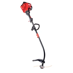
Fig. 5
Knob
Tighten
Loosen
Fig. 7
Fig. 6
Coupler
Attachment
Release Button
Guide Recess
Primary Hole
INSTALLING AND REMOVING THE ATTACHMENT
The coupler enables the use of various optional attachments.
Installing the Attachment
1. Remove the hanger cap from the attachment. Keep the hanger
cap for use when storing the attachment. If present, remove the
gray spacer from the coupler.
2. Set the unit on a flat, level surface.
3. Turn the knob counterclockwise to loosen the coupler (Fig. 5).
4. Align the release button with the guide recess (Fig. 7).
5. Push the attachment straight into the coupler (Fig. 6) until the
release button snaps firmly into the primary hole (Fig. 7).
6. Turn the knob clockwise to tighten the coupler (Fig. 5).
Removing the Attachment
1. Set the unit on a flat, level surface.
2. Turn the knob counterclockwise to loosen the coupler (Fig. 5).
3. Press and hold the release button (Fig. 7).
4. Pull the attachment straight out of the coupler (Fig. 6).
WARNING:
Before operating the unit, make sure the
release button is fully snapped into the primary hole and the
knob is securely tightened.
WARNING:
Unless specified otherwise, the release
button should be snapped into the primary hole only. Using
the wrong hole could lead to personal injury or damage to
the unit.
WARNING:
Before using any attachment, read and
understand the manual that came with the attachment.
Follow all safety information contained within.
WARNING:
To avoid serious personal injury and
damage to the unit, shut the unit off before removing or
installing an attachment.
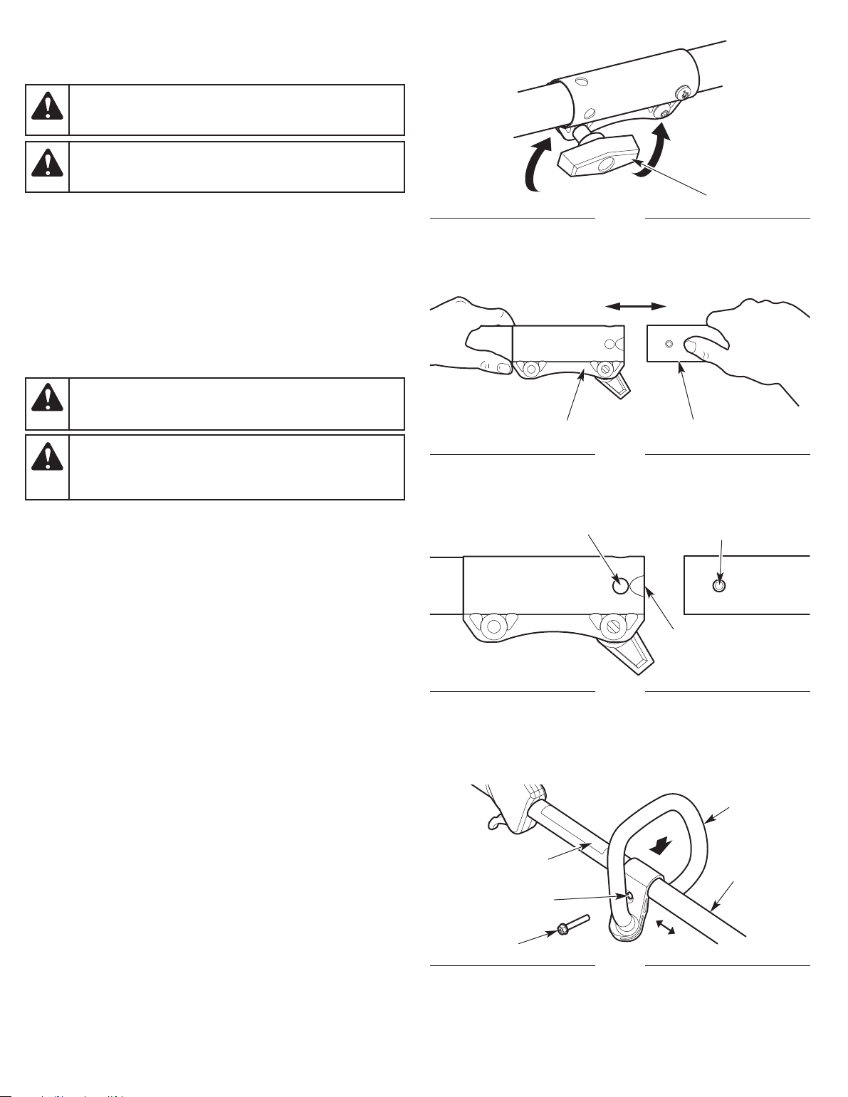
INSTALLING AND ADJUSTING THE HANDLE
Installing the Handle
1. Push the handle down onto the upper shaft housing (Fig. 8).
Make sure the bolt hole faces to the right (Fig. 8).
2. Insert the bolt into the bolt hole and push it through (Fig. 8).
Tighten the bolt with a flat-head screwdriver, but do not tighten
the bolt completely .
3. Hold the unit in the operating position (Fig. 12). Move the handle
up or down the upper shaft housing to a comfortable location
(Fig. 8). Make sure the handle is positioned beyond the end of the
safety label (Fig. 8).
4. Tighten the bolt with a flat-head screwdriver until the handle is
secure.
Adjusting the Handle
If the handle requires adjustment:
1. Loosen the bolt with a flat-head screwdriver (Fig. 8).
2. Hold the unit in the operating position (Fig. 12). Move the handle
up or down the upper shaft housing to a comfortable location
(Fig. 8). Make sure the handle is positioned beyond the end of the
safety label (Fig. 8).
3. Tighten the bolt with a flat-head screwdriver until the handle is
secure.
Fig. 8
Bolt Hole
Handle
Upper Shaft
Housing
Bolt
Safety Label
Loading ...
Loading ...
Loading ...