Loading ...
Loading ...
Loading ...

4
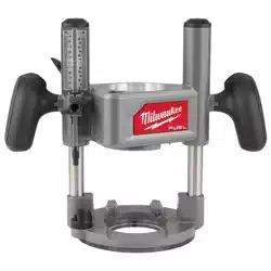
FUNCTIONAL DESCRIPTION
1. Height adjust dial
2. Slide switch
3. Spindle lock
4. Collet/collet nut
5. Height adjust screw
6. Handle
7. Gripping surface
8. Depth adjust button
9. Locking lever
10. Accessory holes
11. Depth rod adjustment
knob
6
7
4
2
1
8
9
10
14
16
13
17
6
11
12
15
18
Plunge base
(Cat. No. 48-10-2838)
Fixed base
19
5
12. Depth indicator
13. Depth scale
14. Plunge release lever
15. Depth rod
16. Micro adjust dial
17. Depth stop turret
18. Edge guide
19. Dust shroud
3
SPECIFICATIONS
Cat. No. ..................................................... 2838-20
Volts.............................................................. 18 DC
Battery Type .................................................M18™
Charger Type................................................M18™
No Load RPM ................................ 12,000 - 25,000
Collet Size ..............................................1/4" & 1/2"
Recommended Ambient
Operating Temperature ......................0°F to 125°F
Plunge Base Cat. No. ......................... 48-10-2838
SYMBOLOGY
Volts
Direct Current
No Load Revolutions per Minute (RPM)
Read Operator's Manual
C
US
UL Listing for Canada and U.S.
ASSEMBLY
WARNING
Recharge only with the charger
specied for the battery. For spe-
cic charging instructions, read the operator’s
manual supplied with your charger and battery.
Removing/Inserting the Battery
To remove the battery, push in the release buttons
and pull the battery pack away from the tool.
WARNING
Always remove the battery pack
any time the tool is not in use.
To insert the battery, slide the pack into the body
of the tool. Make sure it latches securely into place.
WARNING
Only use accessories specically
recommended for this tool. Others
may be hazardous.
Always remove battery from tool before changing
or removing accessories.
Installing/Removing Bases
WARNING
To reduce the risk of injury, DO NOT
use the router if the locking lever
does not hold the console securely in the base.
Check the locking lever screw and tighten if
needed.
Pressing the depth adjust button will cause the
console to drop down, which may cause personal
injury or damage to the tool or workpiece. Make
sure your hand is rmly on the console when
pressing the button.
Fixed Base
1. Open the locking lever (1).
3
1
2
2. Press and hold the depth
adjust button (2) on the
xed base.
3. Insert the console (3)
into the base.
4. Release the button.
5. Close the locking lever.
6. To remove the base,
reverse the procedure.
Loading ...
Loading ...
Loading ...