

Legal Informaon
©2020 Hangzhou Hikvision Digital Technology Co., Ltd. All rights
reserved.
About this Manual
The Manual includes instrucons for using and managing the
Product. Pictures, charts, images and all other informaon
hereinaer are for descripon and explanaon only. The
informaon contained in the Manual is subject to change,
without noce, due to rmware updates or other reasons. Please
nd the latest version of this Manual at the Hikvision website
( hps://www.hikvision.com/ ).
Please use this Manual with the guidance and assistance of
professionals trained in supporng the Product.
Trademarks
and other Hikvision's trademarks
and logos are the properes of Hikvision in various jurisdicons.
Other trademarks and logos menoned are the properes of
their respecve owners.
Disclaimer
TO THE MAXIMUM EXTENT PERMITTED BY APPLICABLE LAW, THIS
MANUAL AND THE PRODUCT DESCRIBED, WITH ITS HARDWARE,
SOFTWARE AND FIRMWARE, ARE PROVIDED “AS IS” AND “WITH
ALL FAULTS AND ERRORS”. HIKVISION MAKES NO WARRANTIES,
EXPRESS OR IMPLIED, INCLUDING WITHOUT LIMITATION,
MERCHANTABILITY, SATISFACTORY QUALITY, OR FITNESS FOR A
PARTICULAR PURPOSE. THE USE OF THE PRODUCT BY YOU IS AT
YOUR OWN RISK. IN NO EVENT WILL HIKVISION BE LIABLE TO YOU
FOR ANY SPECIAL, CONSEQUENTIAL, INCIDENTAL, OR INDIRECT
DAMAGES, INCLUDING, AMONG OTHERS, DAMAGES FOR LOSS OF
BUSINESS PROFITS, BUSINESS INTERRUPTION, OR LOSS OF DATA,
CORRUPTION OF SYSTEMS, OR LOSS OF DOCUMENTATION,
WHETHER BASED ON BREACH OF CONTRACT, TORT (INCLUDING
NEGLIGENCE), PRODUCT LIABILITY, OR OTHERWISE, IN
CONNECTION WITH THE USE OF THE PRODUCT, EVEN IF
HIKVISION HAS BEEN ADVISED OF THE POSSIBILITY OF SUCH
DAMAGES OR LOSS.
YOU ACKNOWLEDGE THAT THE NATURE OF INTERNET PROVIDES
FOR INHERENT SECURITY RISKS, AND HIKVISION SHALL NOT TAKE
ANY RESPONSIBILITIES FOR ABNORMAL OPERATION, PRIVACY
LEAKAGE OR OTHER DAMAGES RESULTING FROM CYBER-ATTACK,
HACKER ATTACK, VIRUS INSPECTION, OR OTHER INTERNET
SECURITY RISKS; HOWEVER, HIKVISION WILL PROVIDE TIMELY
TECHNICAL SUPPORT IF REQUIRED.
YOU AGREE TO USE THIS PRODUCT IN COMPLIANCE WITH ALL
APPLICABLE LAWS, AND YOU ARE SOLELY RESPONSIBLE FOR
ENSURING THAT YOUR USE CONFORMS TO THE APPLICABLE LAW.
ESPECIALLY, YOU ARE RESPONSIBLE, FOR USING THIS PRODUCT IN
A MANNER THAT DOES NOT INFRINGE ON THE RIGHTS OF THIRD
PARTIES, INCLUDING WITHOUT LIMITATION, RIGHTS OF
i

PUBLICITY, INTELLECTUAL PROPERTY RIGHTS, OR DATA
PROTECTION AND OTHER PRIVACY RIGHTS. YOU SHALL NOT USE
THIS PRODUCT FOR ANY PROHIBITED END-USES, INCLUDING THE
DEVELOPMENT OR PRODUCTION OF WEAPONS OF MASS
DESTRUCTION, THE DEVELOPMENT OR PRODUCTION OF
CHEMICAL OR BIOLOGICAL WEAPONS, ANY ACTIVITIES IN THE
CONTEXT RELATED TO ANY NUCLEAR EXPLOSIVE OR UNSAFE
NUCLEAR FUEL-CYCLE, OR IN SUPPORT OF HUMAN RIGHTS
ABUSES.
IN THE EVENT OF ANY CONFLICTS BETWEEN THIS MANUAL AND
THE APPLICABLE LAW, THE LATER PREVAILS.
ii

Regulatory
FCC
Please take that changes or not expressly
approved by the party responsible for compliance could void the
user's authority to operate the equipment.
FCC compliance: This equipment has been tested and found to
comply with the limits for a Class A digital device, pursuant to
part 15 of the FCC Rules. These limits are designed to provide
reasonable
against harmful interference when the
equipment is operated in a commercial environment. This
equipment generates, uses, and can radiate radio frequency
energy and, if not installed and used in accordance with the
manual, may cause harmful interference to radio
of this equipment in a
area is likely to cause harmful interference in which case the user
will be required to correct the interference at his own expense.
FCC
This device complies with part 15 of the FCC Rules. is
subject to the following two
1. This device may not cause harmful interference.
2. This device must accept any interference received, including
interference that may cause undesired
EU Conformity Statement
This product and - if applicable - the supplied accessories
too are marked with "CE" and comply therefore with the
applicable harmonized European standards listed under
the EMC
2014/30/EU, the RoHS 2011/
65/EU.
2012/19/EU (WEEE Products marked with this
symbol cannot be disposed of as unsorted municipal waste
in the European Union. For proper recycling, return this
product to your local supplier upon the purchase of
equivalent new equipment, or dispose of it at designated
points. For more see:
www.recyclethis.info .
2006/66/EC This product contains a
that cannot be disposed of as unsorted municipal
waste in the European Union. See the product
for The
is marked with this symbol, which may include
to indicate cadmium (Cd), lead (Pb), or mercury
(Hg). For proper recycling, return the
to your
supplier or to a designated
point. For more
see: .
iii

Industry Canada ICES-003 Compliance
This device meets the CAN ICES-3 (A)/NMB-3(A) standards
requirements.
iv

Preface
Applicable Models
This manual is applicable to DS-3E15XX series switches.
Symbol Convenons
The symbols that may be found in this document are dened as
follows.
Symbol Descripon
Danger
Indicates a hazardous situaon which, if not avoided,
will or could result in death or serious injury.
Cauon
Indicates a potenally hazardous situaon which, if
not avoided, could result in equipment damage, data
loss, performance degradaon, or unexpected
results.
Note
Provides addional informaon to emphasize or
supplement important points of the main text.
v

Safety Instrucon
Danger
•
This is a class A product and may cause radio interference in
which case the user may be required to take adequate
measures.
•
In the use of the product, you must be in strict compliance with
the electrical safety
regulaons of the naon and region.
•
The socket-outlet shall be installed near the device and shall be
easily accessible.
•
The device must be connected to an earthed mains socket-
outlet.
•
Install the device according to the instrucons in this manual.
•
indicates hazardous live and the external wiring connected
to the terminals requires
installaon by an instructed person.
•
Keep body parts away from fan blades. Disconnect the power
source during servicing.
•
Never place the device in an unstable locaon. The device may
fall, causing serious personal injury or death.
•
This device is not suitable for use in locaons where children
are likely to be present.
•
CAUTION: Risk of explosion if the baery is replaced by an
incorrect type.
•
Improper replacement of the baery with an incorrect type
may defeat a safeguard (for example, in the case of some
lithium
baery types).
•
Do not dispose of the
baery into re or a hot oven, or
mechanically crush or cut the
baery, which may result in an
explosion.
•
Do not leave the
baery in an extremely high temperature
surrounding environment, which may result in an explosion or
the leakage of ammable liquid or gas.
•
Do not subject the
baery to extremely low air pressure, which
may result in an explosion or the leakage of
ammable liquid
or gas. Dispose of used baeries according to the instrucons.
Cauon
•
CAUTION: Double pole/Neutral fusing. Aer operaon of the
fuse, parts of the device that remain energized might represent
a hazard during servicing.
•
The device has been designed, when required, modied for
connecon to an IT power distribuon system.
•
This device is suitable for mounng on concrete or other non-
combusble surface only.
•
The
venlaon should not be impeded by covering the
venlaon openings with items, such as newspapers, table-
cloths, curtains, etc. The openings shall never be blocked by
placing the device on a bed, sofa, rug or other similar surface.
•
No naked ame sources, such as lighted candles, should be
placed on the device.
vi

•
The device shall not be exposed to dripping or splashing and
that no objects lled with liquids, such as vases, shall be placed
on the device.
•
Burned ngers when handling the cover area of the device.
Wait one-half hour
aer switching o before handling the
parts.
•
CLASS 1 LASER PRODUCT
vii

1 Introducon
1.1 Product Introducon
DS-3E15XX series switches (hereinaer referred to as "the
device") are layer 2 switches, supporng extend mode with up to
250-meter transmission distance on the basis of high-
performance access. The switches support client management,
network topology management, link
aggregaon, port
management and so on. The switches are suitable for small-scale
LAN device access.
1.2 Packing List
DS-3E1508 Series DS-3E1516/24 Series
Switch × 1 × 1
Power Adapter × 1 -
AC Power Cord - × 1
Screw - × 4
L-Shaped Bracket - × 2
Quick Start Guide × 1 × 1
1.3 Appearance
Dierent models of devices may have dierent appearances. The
following pictures are only for illustraon.
Front Panel
Figure 1-1 DS-3E1508 Series
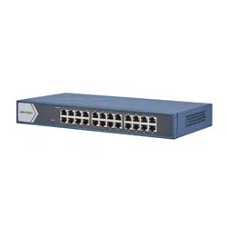
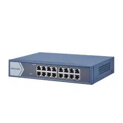
Figure 1-2 DS-3E1516 Series
Note
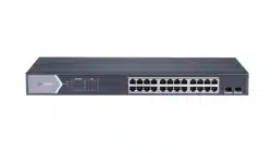
The front panel of DS-3E1524 switch is similar to that of
DS-3E1516, with dierences on 24 gigabit RJ45 ports.
Rear Panel
1

Figure 1-3 DS-3E1508 Series
Figure 1-4 DS-3E1516/24 Series
Port/Indicator Descripon
Indicator/Port Descripon
PWR Indicator
•
Solid: The switch is powered on normally.
•
Unlit: No power supply connected or power
supply is abnormal.
LINK/ACT Indicator
•
Solid: The port is connected.
•
Flashing: The port is transming data.
•
Unlit: The port is disconnected or connecon is
abnormal.
Gigabit RJ45 Port Used for devices connecon via network cables.
Grounding Terminal
Used for connecng to the grounding cable to
protect the switch from lightning.
Power Supply
Use the aached power cord to connect the switch
to socket.
2 Installaon
Please select the appropriate installaon method according to
the actual needs.
Before You Start
•
Ensure that the desktop or rack is stable and rm enough.
•
Keep the room
well-venlated. Keep at least 10 cm distance
around the device for heat dissipaon.
•
Keep at least 1.5 cm vercal distance between two adjacent
devices for rack-mount
installaon.
2.1 Desk-Mounted Installaon
Place the device on the desk.
2.2 Wall-Mounted Installaon
Steps
1.
Check the distance between the two hanging holes on the rear
cover of the device.
2.
Insert two M4 screws into the wall.
2

Note
•
Please prepare two M4 screws.
•
Ensure that the distance between the two screws equals
that between the two hanging holes.
•
Set aside at least 4 mm screws outside the wall.
3.
Align the hanging holes with screws, and hang the device on
the screws.
Figure 2-1 Wall-Mounted Installaon
2.3 Rack-Mounted Installaon
Steps
1.
Check the grounding and stability of the rack.
2.
Use the aached screws to x the two L-shaped brackets to the
sides of the switch.
Figure 2-2 Fix L-Shaped Brackets
3.
Place your switch on the rack,
x it to the rack with self-
prepared screws to stably install your switch.
Figure 2-3 Fix to the Rack
3 Grounding
3.1 Connecng the Grounding Cable
Grounding is used to quickly release overvoltage and overcurrent
induced by lightening for switch, and to protect personal safety.
Select the appropriate grounding method according to your
needs.
3.1.1 With Grounding Bar
3

If a grounding bar is available at the installaon site, follow the
steps below.
Steps
1.
Connect one end of the grounding cable to the binding post on
the grounding bar.
2.
Connect the other end of the grounding cable to the grounding
terminal of the device and
x the screw.
Figure 3-1 Grounding with Grounding Bar
3.1.2 Without Grounding Bar
If there is no grounding bar but the earth is nearby and the
grounding body is allowed to be buried, follow the steps below.
Steps
1.
Bury an angle steel or steel pipe (≥ 0.5 m) into the mud land.
2.
Weld one end of the grounding cable to the angle steel or steel
pipe and embalm the welding point via
electroplang or
coang.
3.
Connect the other end of the grounding cable to the grounding
terminal.
Figure 3-2 Grounding with Angle Steel
3.2 Connecng RJ45 Port
Use a network cable to connect the device to the RJ45 port of a
peer device such as network camera, NVR, switch, etc.
4

Figure 3-3 RJ45 Port Connecon
4 Powering on the Device
Please use the aached power cord in package to power on the
device.
Before powering your switch, make sure that:
•
The operang power supply is compliant with rated input
standard.
•
Port cables and grounding cables are correctly connected.
•
If there is outdoor cabling, connect a lightning rod and
lightening arrester to the cable.
Cauon
PoE power supply line and strong wire cannot be wired together,
otherwise PD equipment or switch ports will be burnt.
5 Device Management
The device can be congured and managed through iVMS-4200
soware, mainly including network parameter conguraon, port
conguraon, link aggregaon conguraon, network topology
display and so on.
Note
•
This chapter will briey introduce the device management
through the iVMS-4200 soware. For other funcons, please
refer to User Manual of iVMS-4200 Client Soware.
•
All pictures in this manual are for illustraon only, and the
specic interface is subject to the actual interface.
5.1 Acvang Devices
For the inacve devices, you are required to create a password to
acvate them before they can be added to the soware and work
properly.
Before You Start
Make sure the device to be
acvated is connected to the network
and is in the same subnet with the PC running the client.
5

Steps
Note
This funcon should be supported by the device.
1.
Enter the Device Management page.
2.
Click Device tab on the top of the right panel.
3.
Click Online Device to show the online device area at the
boom of the page.
The searched online devices are displayed in the list.
4.
Check the device status (shown on Security Level column) and
select an
inacve device.
Figure 5-1 Online Inacve Device
5.
Click Acvate to open the Acvaon dialog.
6.
Create a password in the password
eld, and conrm the
password.
Cauon
The password strength of the device can be automacally
checked. We highly recommend you change the password of
your own choosing (using a minimum of 8 characters, including
at least three kinds of following categories: upper case leers,
lower case leers, numbers, and special characters) in order to
increase the security of your product. And we recommend you
change your password regularly, especially in the high security
system, changing the password monthly or weekly can
beer
protect your product.
Proper conguraon of all passwords and other security
sengs is the responsibility of the installer and/or end-user.
7.
Click OK to
acvate the device.
5.2 Adding Devices
The client provides various device adding modes including IP/
domain, IP segment, cloud P2P, ISUP protocol, and HiDDNS. The
client also supports imporng mulple devices in a batch when
there are large amount of devices to be added. The
secon only
introduces one mode, namely, adding a detected online device.
Steps
1.
Enter the Device Management module.
2.
Click Device tab on the top of the right panel.
3.
Click Online Device to show the online device area.
The searched online devices are displayed in the list.
4.
Select an online device in the Online Device area, and click
Add to open the device adding window.
Note
For the inacve device, you need to create the password for it
before you can add the device properly. For detailed steps,
refer to Acvang Devices.
6

5.
Enter the required informaon.
Name
Enter a descripve name for the device.
IP Address
Enter the device's IP address. The IP address of the device is
obtained
automacally in this adding mode.
Port
You can customize the port number. The port number of the
device is obtained automacally in this adding mode.
User Name
By default, the user name is admin.
Password
Enter the device password.
Cauon
The password strength of the device can be automacally
checked. We highly recommend you change the password of
your own choosing (using a minimum of 8 characters,
including at least three kinds of following categories: upper
case leers, lower case leers, numbers, and special
characters) in order to increase the security of your product.
And we recommend you change your password regularly,
especially in the high security system, changing the
password monthly or weekly can
beer protect your
product.
Proper
conguraon of all passwords and other security
sengs is the responsibility of the installer and/or end-user.
6.
Check Synchronize Time to synchronize the device me with
the PC running the client aer adding the device to the client.
7.
Click Add.
6 Get More
Informaon
Scan the QR code below for iVMS-4200 soware operaons.
7