Loading ...
Loading ...
Loading ...

The following are descriptions of how to install on a wall using WV-Q124 (mount bracket) and
WV-Q122A (wall mount bracket).
Installations/Connections
[4] Fix the camera to the attachment plate
w Apply waterproof treatment to the joints of the cables.
Adequate waterproof treatment is required for the cables when installing the camera with cables
exposed. The camera body is waterproof, but the cable ends are not waterproof. Be sure to use
the waterproof tape provided with the camera at the points where the cables are connected and
apply waterproof treatment in the following procedure. Failure to observe this or use of a tape
other than the provided waterproof tape (such as a vinyl tape) may cause water leakage resulting
in malfunction.
Separately apply waterproof treatment to the network cable and other cables as shown in the
illustration below.
IMPORTANT:
• Also waterproof the 2P power cable (provided with the camera), 4P alarm cable (provided
with the camera), and external connections in the same way.
• Stretch the tape by approx. twice (see the illus-
tration at right) and wind it around the cable.
Insufficient tape stretch causes insufficient water-
proofing.
• Waterproof grade (JIS IP66 or equivalent) is
applied to this product only when it is installed
correctly and also an appropriate waterproof
treatment is applied.
The inner side of WV-Q124 (mount bracket) is
not waterproofed.
• When a LAN cable cover is provided with the
camera in the package, attach the LAN cable
cover to the cable as shown in the illustration
and fix it by sliding to the direction indicated by
the arrow. The connector of the LAN cable used
with this camera must meet the following restric-
tions.
[2] Fix the cable with the inner cover of WV-Q124
[3] Attach the attachment plate to the cover part of the WV-Q124
e After connecting the cables to the camera, align the OPEN mark at the side of the camera enclo-
sure to the claw of the attachment plate (provided with the camera). Then, insert the attachment
mounting screws (2 or 3 points) at the bottom of the camera into the holes of the attachment
plate.
After that, move the LOCK mark to the point where the claw of the attachment plate is located by
rotating the camera body clockwise by approx. 15° to fix temporarily.
* Refer to the operating instructions of the connected camera for information on how to mount the
camera.
<For WV-SW458>
Tighten the camera fixing screw located at the enclosure of the camera to fix the attachment plate
and the camera. (Recommended tightening torque: 0.78 N·m {0.58 lbf·ft})
IMPORTANT:
• Enclosure is fixed at the installation auxiliary wire to the camera body, please do not remove the
installation auxiliary wire.
Note:
• As for the enclosure fixing screw, there are three screws models and four screws models
depending on the camera model.
Refer to the operating instructions of the camera for further information.
2. Adjust images from the camera.
* Refer to the operating instructions of the camera for further information on how to adjust.
3. After completing the adjustment, attach the enclosure back to the original position and fix it with
the enclosure fixing screws (3 or 4 screws).
IMPORTANT: This caution shall be applied to all the cameras as described above.
• Be sure to tighten the camera fixing screw. Failure to observe this may cause camera trouble
due to camera falling.
(Recommended tightening torque: 0.78 N·m {0.58 lbf·ft})
* The upper right illustration is provided as an example of attaching the attachment plate for a camera
model having three attachment mounting screws.
<For cameras other than the above>
1. Loosen the fixing screws (3 or 4 screws)
of the enclosure using the bit and remove
the enclosure from the camera body.
Then, fix the camera with the camera fix-
ing screw.
(Recommended tightening torque:
0.78 N·m {0.58 lbf·ft})
q Pass the cables from the wall to the WV-Q122A.
Adjust the length of the cables so that the cables
of approx. 300 mm {11-13/16 inches} come out
from the opening of the WV-Q122A.
Note:
• Do not bundle the cables (Ethernet cable,
power cable, etc.) during installation.
Mounting of A inner cover (accessory) may
become difficult. (The provided illustration
shows the Ethernet cable as a representa-
tive image.)
w Fix the WV-Q122A with M10 screws (locally pro-
cured) or four anchors (locally procured).
Minimum pull-out strength: 823 N {185 lbf}/
per 1 pc.
* Refer to the operating instructions of the mount
bracket (WV-Q122A) for further information on
how to fix.
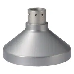
e Attach the cover part of the WV-Q124 to the
WV-Q122A, and then fix it with M6 hex socket
screws (provided with the wall mount bracket).
(A hex wrench for M6 is required.)
(Recommended tightening torque: 2.45 N·m
{1.81 lbf·ft})
* Fix the cover so that the nameplate of the
WV-Q124 comes in front of the WV-Q122A.
r After fixing the WV-Q124 on the WV-Q122A, lay the cables as shown in the upper right illustration
and confirm that the ends of the cables reach the cable line inside the cover of the WV-Q124.
q Prepare the attachment plate (provided
with the camera) and the fixing screws for
attachment plate (provided with the cam-
era: M4 × 8 mm {5/16 inches}).
w Pass the cables through the attachment
plate.
e Align the “⇧TOP” mark on the attachment
plate with the front of WV-Q122A (wall
mount bracket).
r Fix the attachment plate to the cover part
of the WV-Q124 with the fixing screws for
attachment plate.
(Recommended tightening torque:
0.78 N·m {0.58 lbf·ft})
r Fix the camera to the attachment plate.
Fix the camera and adjust images.
<For WV-SFV481>
1. Loosen two of the sub cover fixing screws
using the bit (provided with the camera) and
remove the sub cover of the camera.
Then, tighten the camera fixing screw to fix the
attachment plate and the camera.
(Recommended tightening torque: 0.78 N·m
{0.58 lbf·ft})
2. Attach the sub cover back to the original posi-
tion and fix with two of the sub cover fixing
screws.
IMPORTANT:
• When using WV-SFV481 or WV-SW458 with a SD memory card, insert the SD memory card to
the camera before mounting the camera onto the WV-Q124.
q Wire the cables as shown below.
Applicable models:
WV-SFV481, WV-SW458, WV-SW559,
WV-SW355, WV-SFV631L, WV-SFV631LT,
WV-SFV611L, WV-SFV311
* WV-SFV481 is used as an example in the
right illustration.
q Connect the cables passed through the
plate in section [3] with the cables from
the camera.
④
②
③
①
②
③
④
* The sub cover is omitted in the illustration.
* The enclosure is omitted in the illustration.
WV-SFV631L is used as an example in the
above illustration.
w Fix A inner cover (accessory) using B screw
A (M3 × 8 mm {5/16 inches}: accessory).
(Recommended tightening torque: 0.78 N·m
{0.58 lbf·ft})
[4] Fix the camera to the attachment plate (continued)
Cable line
Attachment plate
(accessory provided
with the camera)
Cable
Camera
Cables
Nameplate
Cover part of
WV-Q124
Cover part of
WV-Q124
Approx. 300 mm
{11-13/16 inches} from the
opening of WV-Q122A
Fixing screw for
attachment plate x4
(accessory provided with
the camera: M4 x 8 mm
{5/16 inches})
“⇧TOP” mark
A Inner cover
(accessory)
B Screw A (accessory) x3
(Recommended tightening torque: 0.78 N·m {0.58 lbf·ft})
<Example of mounting WV-SFV481>
Claw of the attachment plate
(accessory provided with the camera)
OPEN OPEN
LOCK
Camera
Camera
Camera fixing screw
LOCK
<Example of mounting WV-SFV631L>
Claw of the attachment plate
(accessory provided with the camera)
Camera fixing
screw
<LAN cable> <Alarm input/output cable, power cable, micro-
phone/line input cable, audio output cable>
Wind the tape in ahalf-
overlapping manner.
Wind the tape in a
half-overlapping
manner.
Stretch the tape toapprox.
twice its length.
2x
Max. 16 mm
{5/8 inches}
Max. 14 mm
{9/16 inches}
The hook engages with
the connector terminal
Attachment plate
(accessory provided
with the camera)
Front
direction of
WV-Q122A
(wall mount
bracket)
Nameplate
[1] Fix WV-Q122A (wall mount bracket) on a wall and attach the
cover of WV-Q124 (mount bracket) to the WV-Q122A
1
2
3
Loading ...
Loading ...
Loading ...