
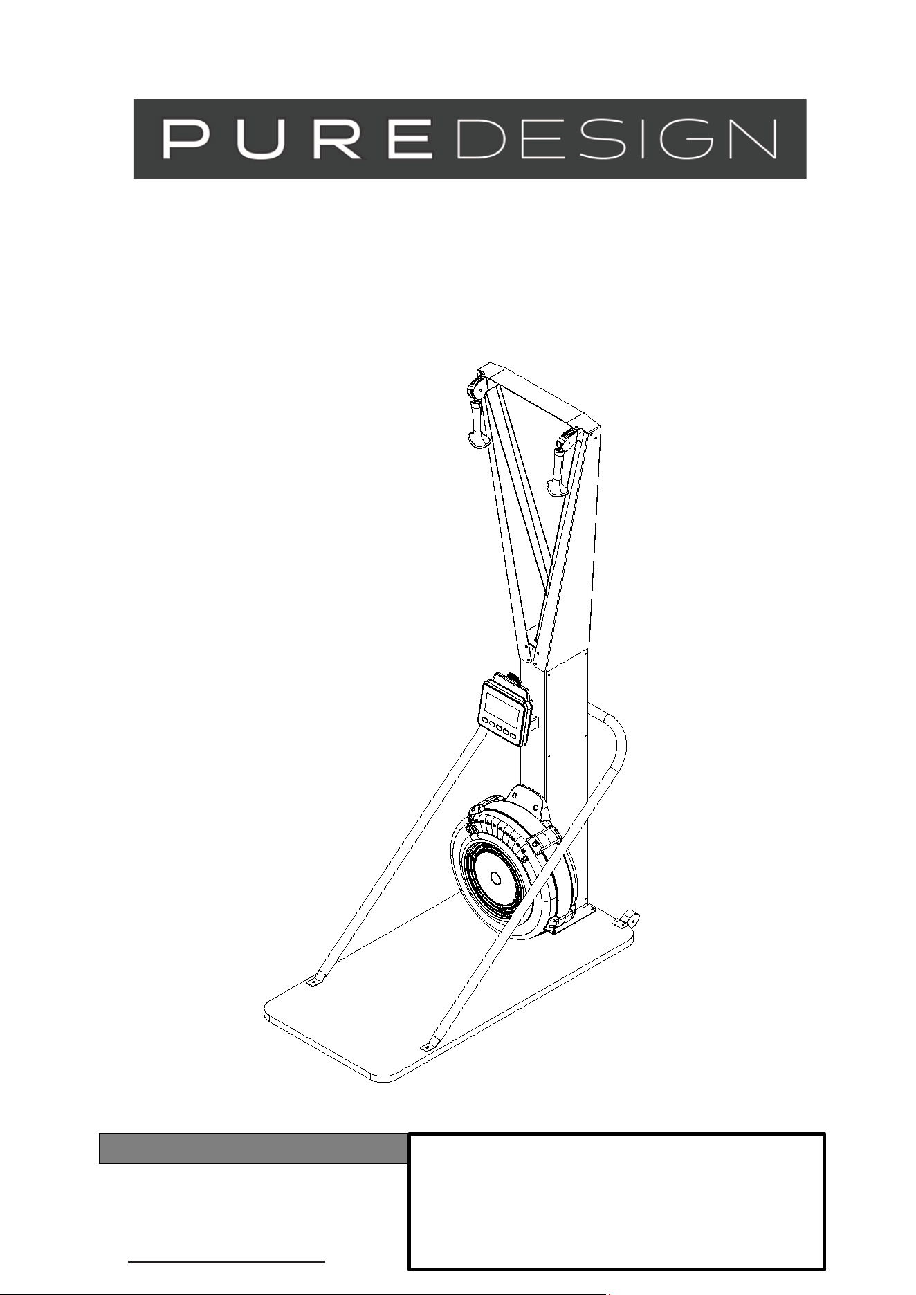
OWNER’S MANUAL
(Free Standing Style)
ITEM NO.: PD-SE10
Product May Vary Slightly From Pictured.
CONTACT INFO
Address: 104 Yale Drive Epping VIC 3076
Phone: 02 9898 1405

2
TABLE OF CONTENTS
Safety Instructions
...................................... 2
Before You Begin
........................................ 3
Equipment Warning, Warning Labels……...4
Hardware Identification Chart
................... 5
Assembly Instructions
.............................. 7
Computer Instructions
............................... 13
Operational Instructions
..........................19
Maintenance
...............................................20
Storage ........................................................ 21
Product Parts Drawing. .............................. 22
Parts List ..................................................... 23
SAFETY INSTRUCTIONS
1.
To reduce the risk of serious injury, read the following Safe Instructions before using the
SKI TRAINER
2.
Save these instructions and ensure that other exercisers read this manual prior to using the
SKI TRAINER
for the firs
t
time.
3.
Read all warnings and cautions posted on the
SKI TRAINER.
4.
The
SKI TRAINER
should only be used after a thorough review of the Owner’s Manual. Make
sure that it is
properly assembled and tightened before use.
5.
We recommend that two people be available for assembly of this product.
6.
Keep children away from the
SKI TRAINER.
Do not allow children to use or play on the
SKI TRAINER.
Keep children and pets away from the
SKI TRAINER
when it is in use.
7.
It is recommended that you place this exercise equipment on an equipment mat.
8.
Set up and operate the
SKI TRAINER
on a solid level surface. Do not position the
SKI TRAINER
on loose rugs o
r
uneven surfaces.
9.
Make sure that adequate space is available for access to and around the
SKI TRAINER.
10.
Before using, inspect the
SKI TRAINER
for worn or loose components, and securely tighten or replace any
worn or loose components prior to use.
11.
Before using, check the condition of the DRIVE CORD (52). Replace the DRIVE CORD (52) if it is damaged or
broken.
12.
Consult a physician prior to commencing an exercise program and follow his/her recommendations in developing
your fitness program. If at any time during exercise you feel faint, dizzy, or experience pain, stop and consult you
r
physician. Failure to follow all warnings and instructions could result in serious injury or death
.
13.
Always choose the workout which best fits your physical strength and flexibility level. Know your limits and train
within them. Always use common sense when exercising.
14.
Do not wear loose or dangling clothing while using the
SKI TRAINER.
15.
Never exercise in bare feet or socks; always wear proper footwear such as running, walking, or cross training
shoes that fit well, provide foot support, and feature non-skid rubber soles.
16.
Be careful to maintain your balance while using, mounting, dismounting, or assembling the
SKI TRAINER,
loss of
balance may result in a fall and bodily injury.
17.
Do not use the U-BAR BRACKET (6) to move the
SKI TRAINER.
It may cause danger. When assembling or
separating the unit, keep all children away and make sure your hands are clear of any pinch point.
18.
The
SKI TRAINER
should be used with training area 24 X 52 X 85 inch (61 X 132 X 215.9 cm).
19.
The
SKI TRAINER
should be used by only one person at a time.
Central Time
Friday, 8:00 AM-3:00 PM, Ce
3
BEFORE YOU BEGIN
Thank you for choosing the SKI TRAINER. We
take great pride in producing this quality
product and hope it will provide many hours of
quality exercise to make you feel better, look
better, and enjoy life to its fullest.
It's a proven fact that a regular exercise program
can improve your physical and mental health.
Too often, our busy lifestyles limit our time and
opportunity to exercise. The
SKI TRAINER
provides a convenient and simple method to begin
your journey of getting your body in shape and
achieving a happier and healthier lifestyle.
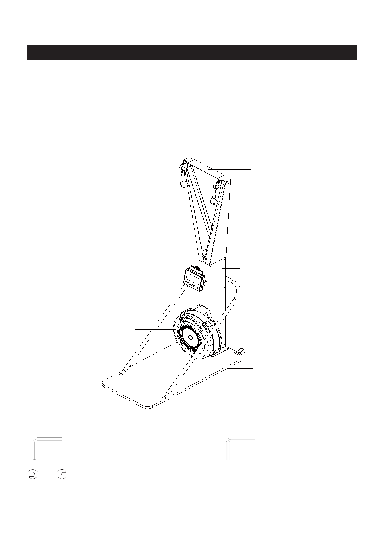
Before reading further, please review the
drawing below and familiarize yourself with the
parts that are labeled.
Read this manual carefully before using the
SKI TRAINER.
THE FOLLOWING TOOLS ARE INCLUDED FOR ASSEMBLY :
Allen Wrench (6mm) Allen Wrench (5mm)
Wrench
Top Bracket
Right Upper Arm
Left Upper Arm
Handle
Drive Cord
Main Body
Monitor
Buttom Fan Shroud
Damper
Damper Cap
Upper Fan Shroud
Body Cover
U-bar Bracket
Transport Wheels
Wooden Base (Option Feature)
4
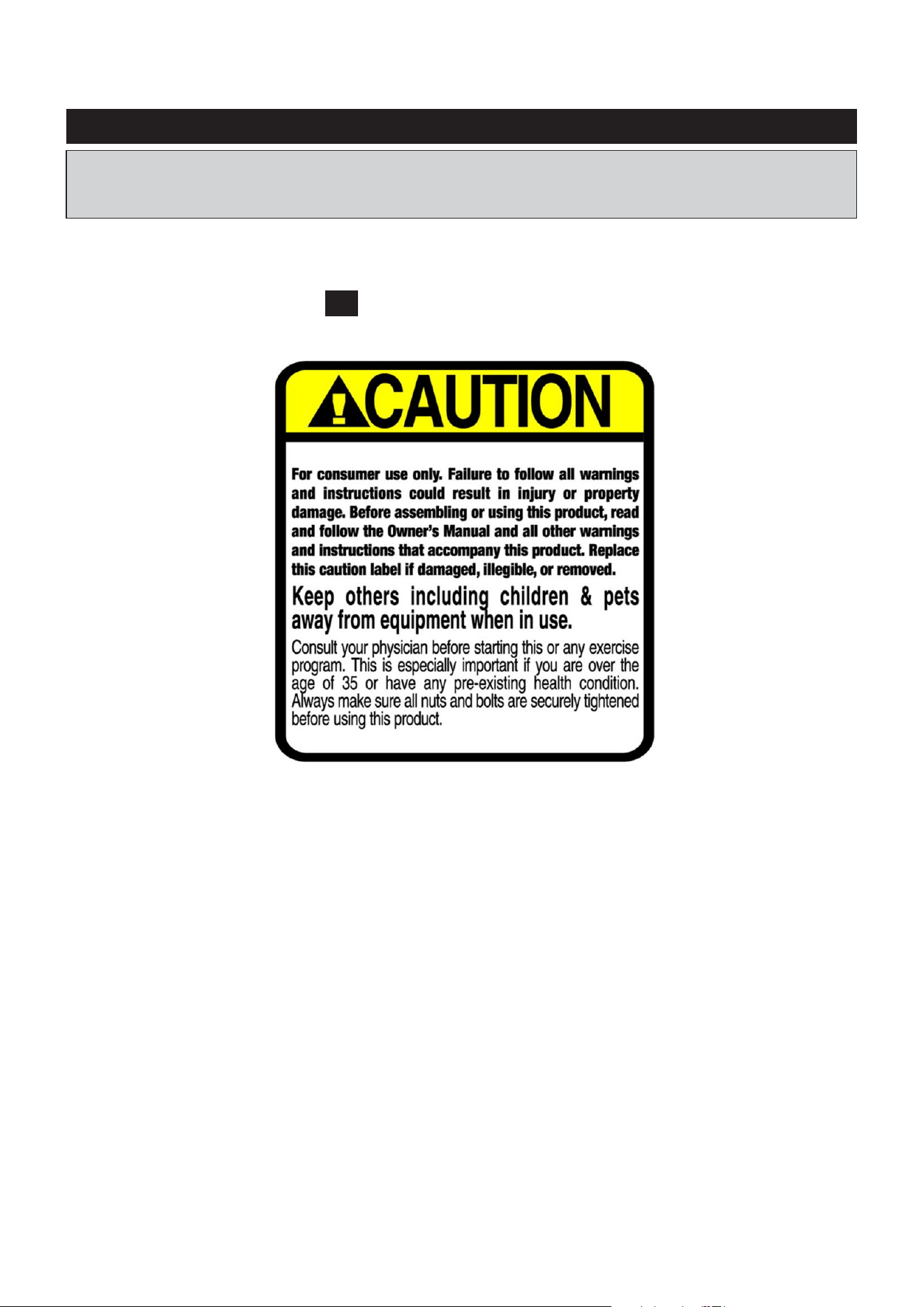
EQUIPMENT WARNING, WARNING LABELS
This chart is provided to help identify the warning label on the SKI TRAINER. Please take a
moment to familiarize yourself with all of the warning labels.
Label is not the same size with actual label
C1 WARNING LABEL
Liquids may spill inside the
machine and cause damage to
the electronic parts.
5
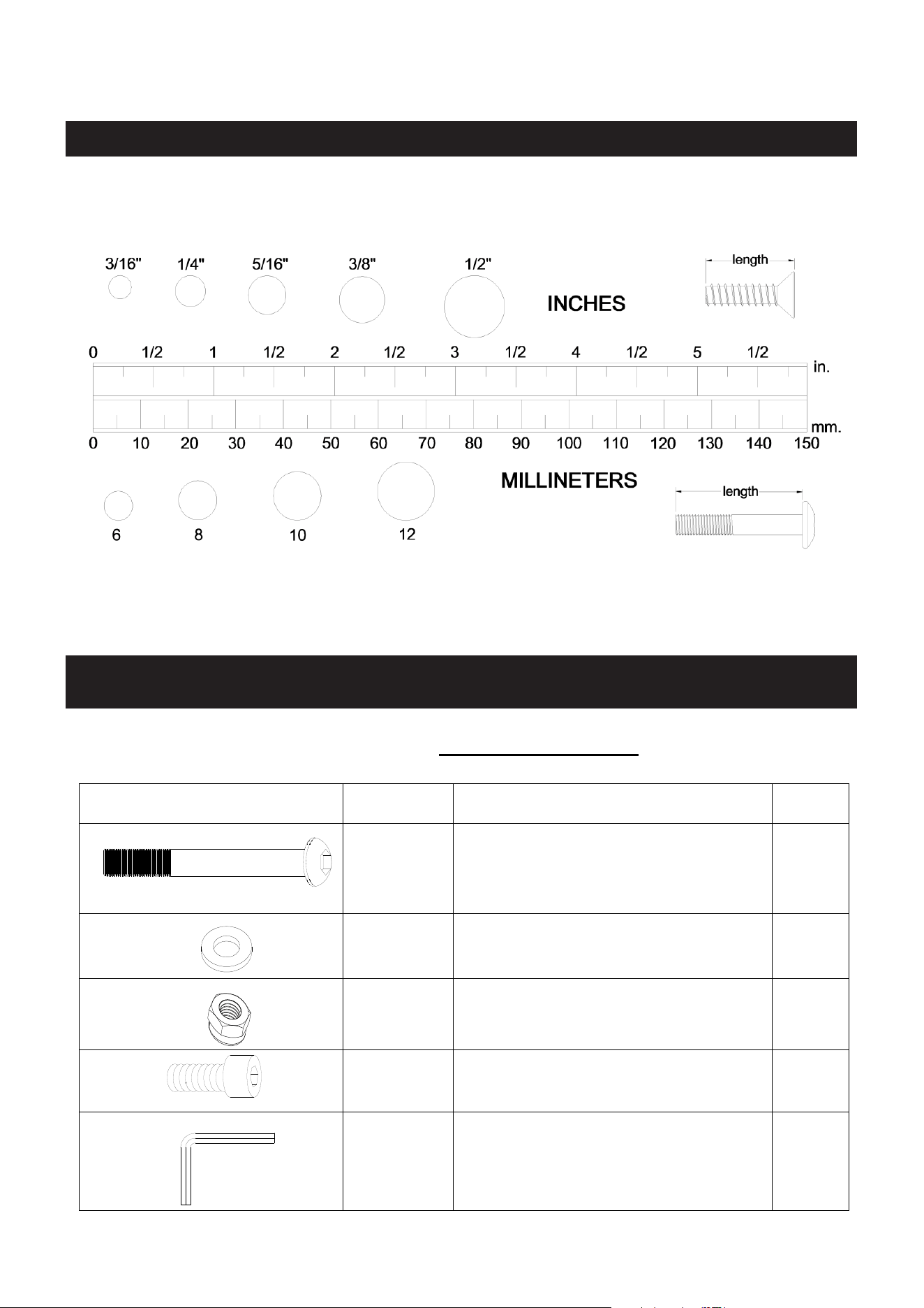
HARDWARE IDENTIFICATION CHART
This chart is provided to help identify the fasteners used in the assembly process. Place the
washers or the ends of the bolts or screws on the circles to check for the correct diameter.
Use the small scale to check the length of the bolts and screws.
NOTICE: The length of all bolts and screws, except those with flat
heads, is measured
from below the head to the end of the bolt or screw. Flat head bolts and screws are
measured from the top of the head to the end of the bolt or screw.
After unpacking the unit, open the hardware bag and make sure that you have all the following
fasteners. Some fasteners may be already attached to the parts.
Below chart include the fasteners for Main Body assembly:
Drawing of Parts
Parts No.
Description
QTY
#82
Button Head Cap Screw, M8x75 mm
1
#71
Flat Washer, M8
13
#72
Nylon Nut, M8
1
#87
Socket Head Cap Screw, M8x15 mm
12
#89
Allen Wrench 6mm
1
6
#88
Wrench 13-15
1
Below chart include the EXTRA fasteners for Wall Mounted Style assembly:
Drawing of Parts
Parts No.
Description
QTY
#54
Socket Head Cap Screw, ST8x50mm
4
#53
Socket Head Cap Screw, M8x35 mm
2
#71
#55
Flat Washer, M8
Flat Washer, Φ22xΦ9x2.0mm
2
4
Below chart include the EXTRA fasteners for Fee Standing Style assembly:
Drawing of Parts
Parts No.
Description
QTY
#84
Button Head Cap screw, M8x50 mm
2
#85
Arc washer, M8
2
#83
Socket Head Cap Screw, M8x30 mm
6
#71
Flat Washer, M8
6
#90
Allen Wrench 5mm
1
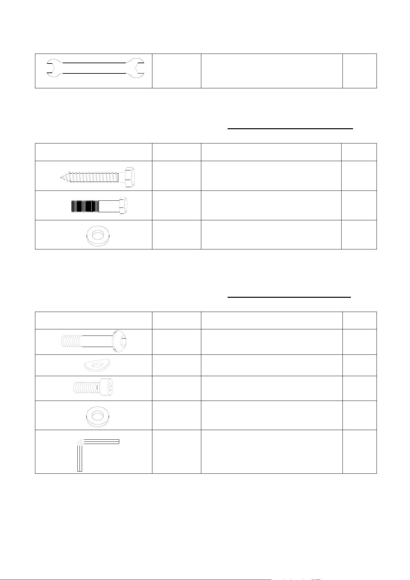
ASSEMBLY INSTRUCTIONS
7
ASSEMBLY INSTRUCTIONS
STEP 1
Attach the Left and Right Upper Arms (2/3) to Main Body (1) to using: 4 PCs of M8x15mm
Socket Head Cap Screw (87) and M8 Flat Washer (71). Then tighten all bolts.
STEP 2
Attach the Left and Right Upper Arms (2/3) to Top Bracket (5) using: 4 PCs of M8x15mm
Socket Head Cap Screw (87) and M8 Flat Washer (71). Then tighten all bolts.
NOTE: Fully tighten bolts at end of above steps
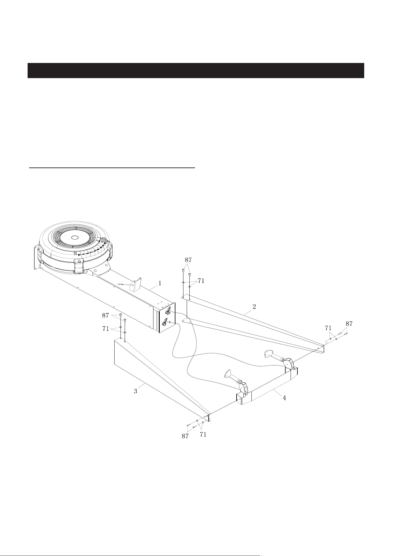
ASSEMBLY INSTRUCTIONS
8
STEP 3
Make the assembly stand up. Tighten the Left and Right Upper Arms (2/3) using: 4 PCs of
M8x15mm Socket Head Cap Screw (87) and M8 Flat Washer (71). Then tighten all bolts.
NOTE: Fully tighten bolts at end of this step.
STEP 4
Remove the clicker from the Drive Cord (52).
#87 M8X15mm 4PCS
#71 M8 4PCS
#89 Allen Wrench 6mm
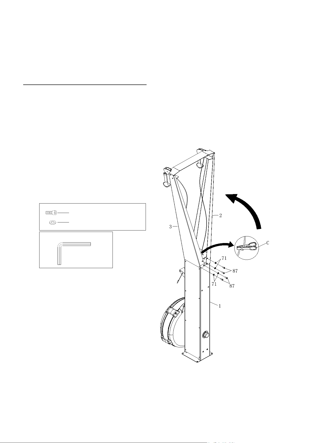
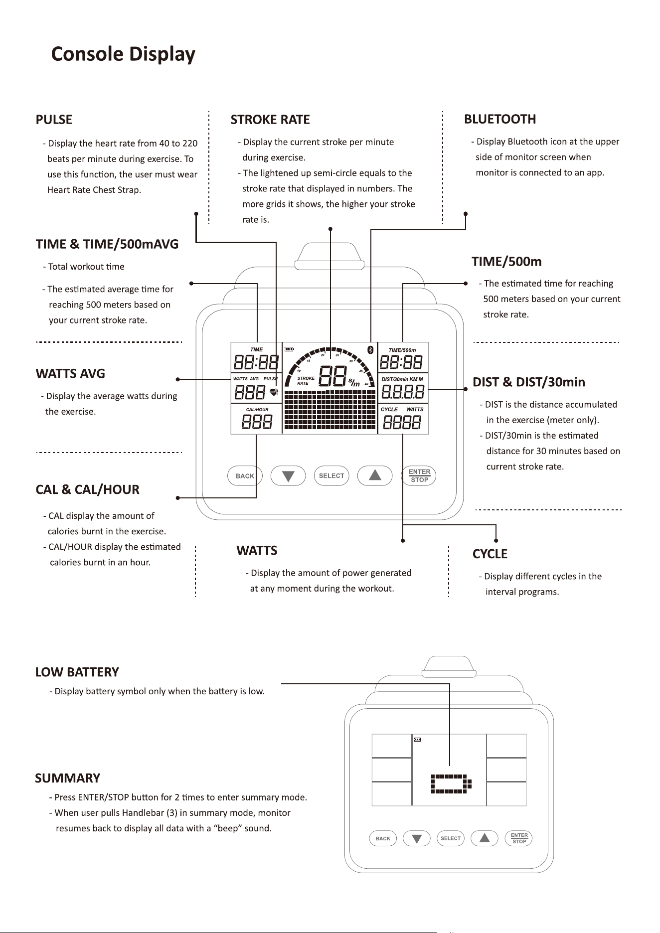
COMPUTER INSTRUCTIONS
9
STEP 5
Attach Cell Phone Bracket (15) to the Console Monitor (14) using Rubber Band (34).
STEP 6
Attach the Console Monitor (14) to the console mounting bracket on Main Body (1) using:1 PC
of M8x75mm Button Head Cap Screw (82), M8 Flat Washer (71), and M8 Nylon Nut (72).
STEP 7
Connect Sensor Cable (17) into the back of the Console Monitor (14a).
17
17
82
14
14a
71
1
72
COMPUTER INSTRUCTIONS
10
STEP 8
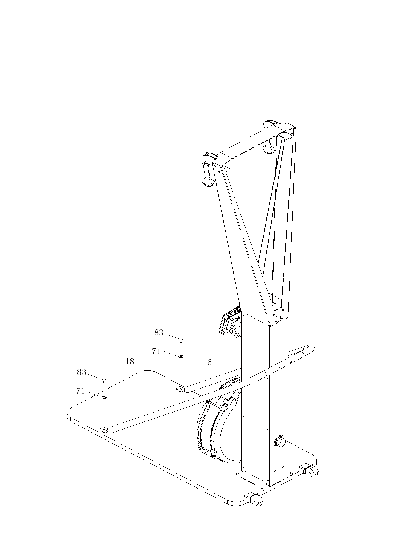
Attach the Main Body (1) to Wooden Base (18) using: 4 PCs of M8x30mm Socket Head
Screw (83) and M8 Flat Washer (71).
NOTE: Fully tighten bolts at end of this step.
83
71
1
83
71
83
71
18
COMPUTER INSTRUCTIONS
11
STEP 9
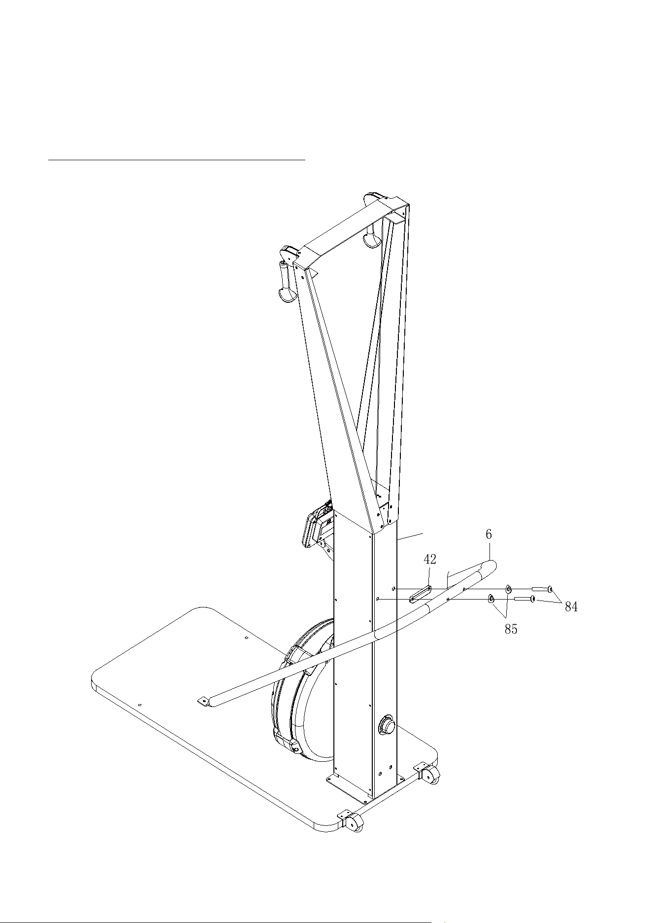
Attach the U-bar Bracket (6) to Main Body (1) using: 2 PCs of M8x50mm Button Head Cap
Screw (84), M8 Arc washer (85), and 1 PC of U-bar Bracket Cushion (42).
NOTE: Fully tighten bolts at end of this step.
1
COMPUTER INSTRUCTIONS
12
STEP 10
Attach the U-bar Bracket (6) to Wooden Base (18) using: 2 PCs of M8x30mm Socket Head
Screw (83) and M8 Flat Washer (71).
Tighten all screws on the U-bar Bracket (6).
NOTE: Fully tighten bolts at end of this step.
COMPUTER INSTRUCTIONS
13
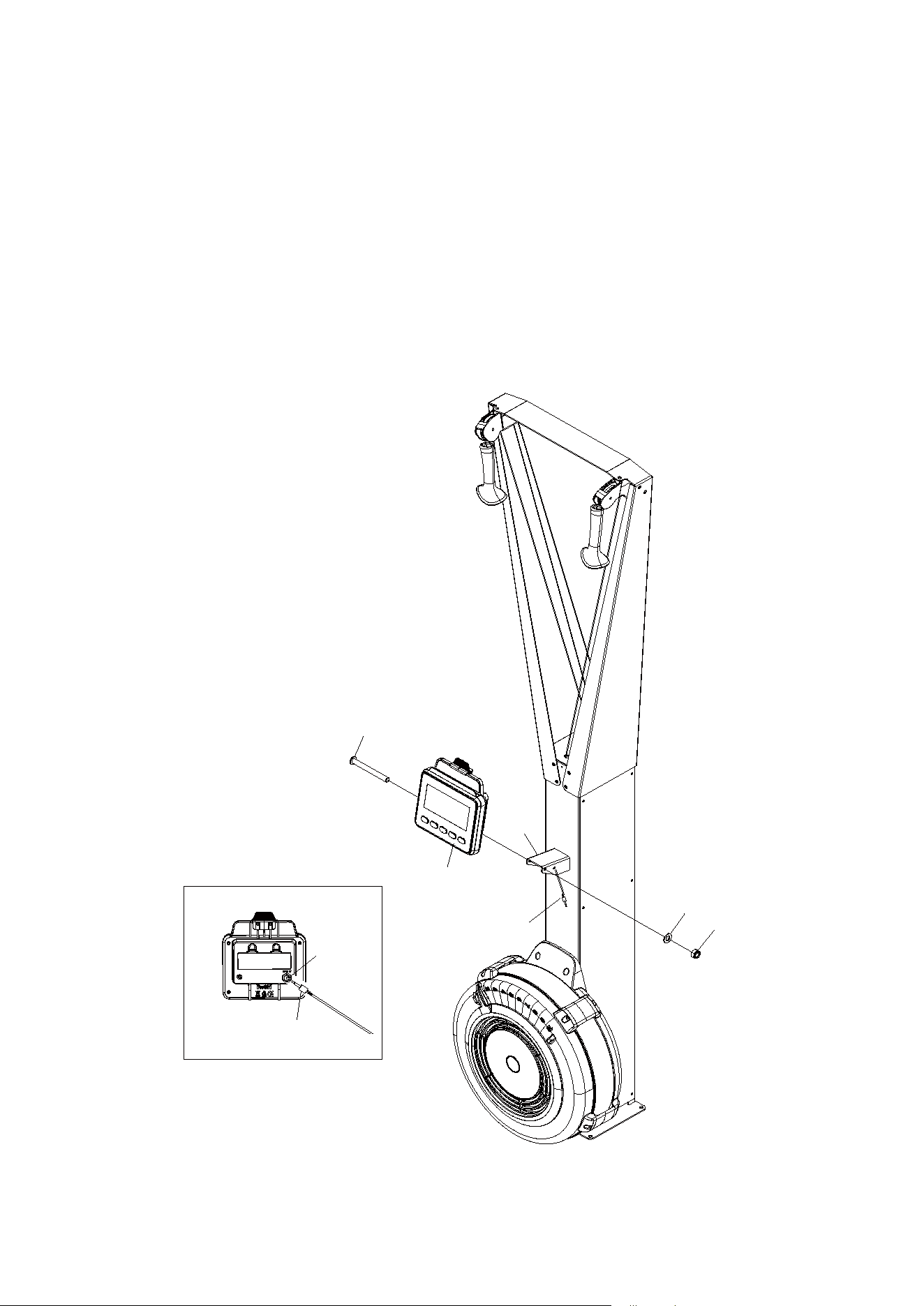
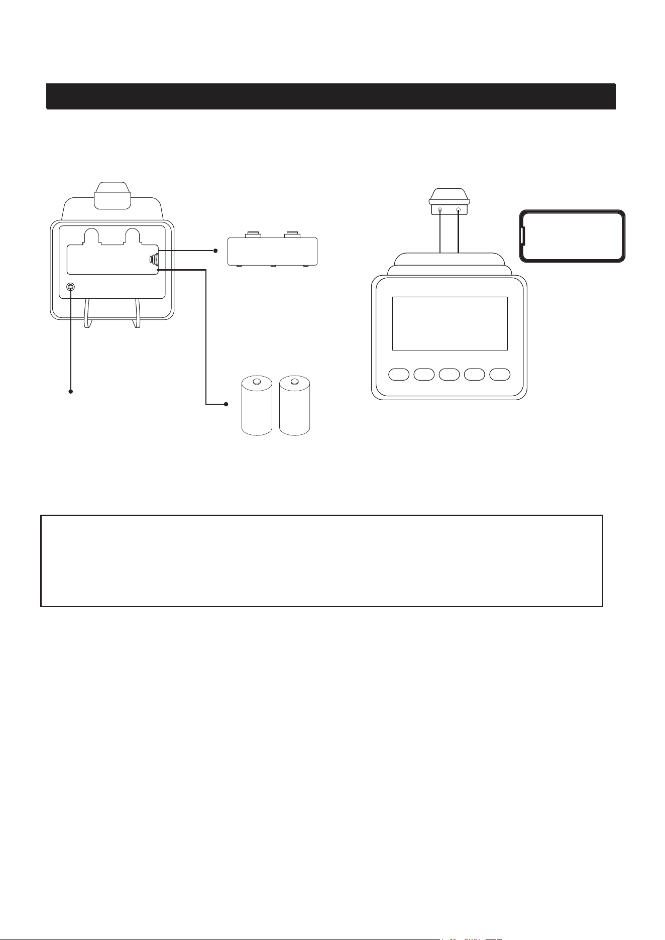
COMPUTER INSTRUCTIONS
COMPUTER INSTRUCTIONS
Your SKI TRAINER u�lizes an air fan system to create resistance for your workout. We
recommend that you use this computer console to vary your workout from session to session and note
your progress toward your fitness goals. When used regularly in this way, the computer console can
become an important source of mo�va�on and interest which will help keep you on track.
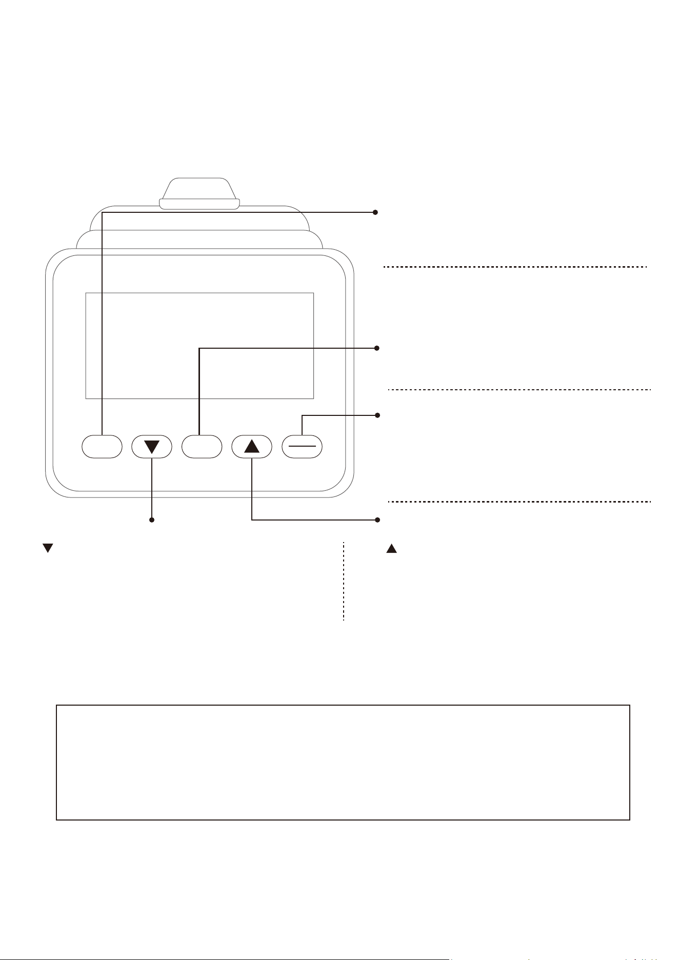
Back View
Front View
Operates on 2 size C
Baeries Cover
Sensor Cable Plugin
Smartphone Holder
C C
POWER ON
- Move the handlebar to start exerciseing in Quick
Start Porgram or press any button to go into IDEL
mode.
- When there is no batteries installed, monitor can
still work in Quick Start Porgram.
POWER OFF
- In IDEL mode, monitor will automatically shut off
after 20 seconds of inactivity.
- When running an interval program, monitor will
automatically shut off after 2 minutes of inactivity.
- In all other programs, monitor will automatically shut
off after 30 seconds of inactivity.
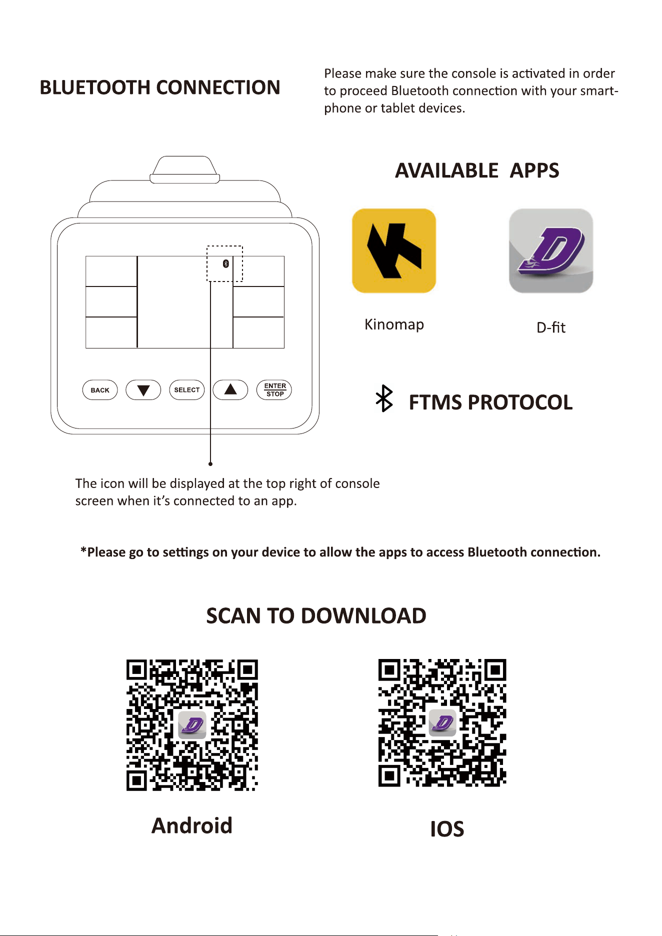
- Monitor will not shut off when connecting to Bluetooth.
Ini�al Setup
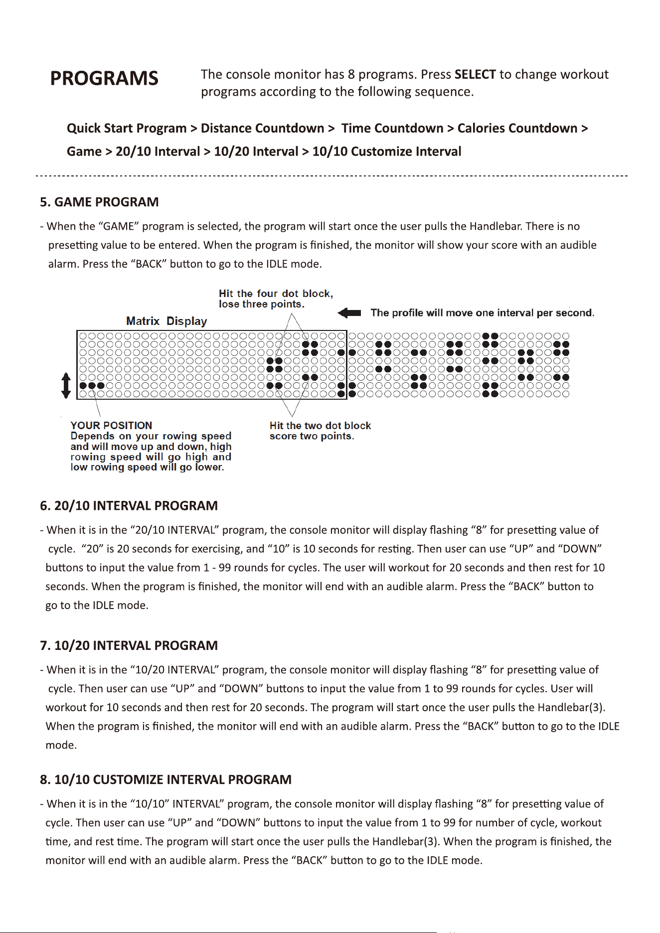
14
Func�on Bu�ons
BACK SELECT
ENTER
STOP
SELECT BUTTON:
- In IDLE mode, press and release SELECT to cycle
through each program op�on. Stop on the program of
your choosing.
NOTE: Default exercising mode is Quick start program.
UP BUTTON :
- Press to increase the preset values. Press the bu�on and
hold it down, the prese�ng value will go faster, release the
bu�on to stop.
DOWN BUTTON :
- Press to decrease the preset values. Press the bu�on and
hold it down, the prese�ng value will go faster, release the
bu�on to stop.
BACK BUTTON:
- When selec�ng the programs, press the bu�on to return
to the previous program.
- When you finish a running program, press the bu�on to
jump into the IDEL mode.
ENTER/STOP BUTTON:
- When selec�ng the programs and prese�ng target
values, press the bu�on to confirm.
- Press the bu�on and hold it down for three seconds to
reset all func�oons to zero and restart the computer.
When the back light is lit, press STOP bu�on the first �me to pause the coun�ng of all func�on values.
Press STOP bu�on the second �me to view the workout summary. Press STOP bu�on the third �me to go
back to IDLE mode.
* When back light is turned off, press any bu�on or keep rowing to turn on the back light.
15

16
17
18
19
OPERATIONAL INSTRUCTIONS
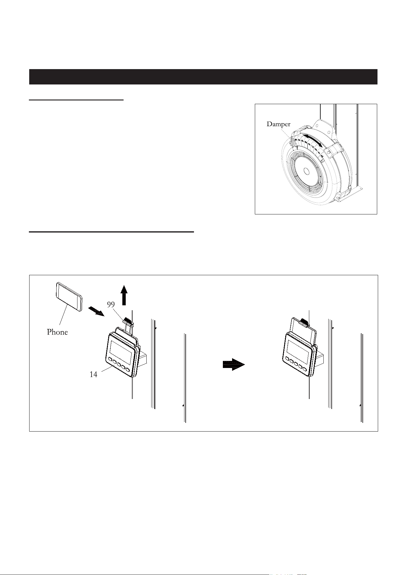
LOAD ADJUSTMENT
There is a Damper (31) built into the Upper Fan Shroud (32).
Move the Indicator in the Damper (31) to point to the numbers on
the Upper Fan Shroud (32) to adjust the load. There are
settings from 1 to 9. Setting #1 will provide the lowest
resistance. Setting #9 will provide the highest resistance.
USING THE CELL PHONE BRACKET
The Cell Phone Bracket (99) can move up and down. Move up the Cell Phone Bracket (99), then
slide the Cell Phone into the gap between the Cell Phone Bracket (99) and the Console
Monitor (14). Move down the Cell Phone Bracket (99) to clip the Cell Phone in position.

20
MAINTENANCE
The safety and integrity designed into the SKI TRAINER can only be maintained when the SKI
TRAINER is regularly examined for damage and wear. Special attention should be given to the
following:
1.
Pull on the Handle (44) and verify that the System provides tension and the seat travel is smooth and
stable.
2.
Clean the revealed surface of Cord Pulley (27) with an absorbent cloth.
3.
Verify that all nuts and bolts are present and properly tightened. Replace missing nuts and bolts.
Tighten loose nuts and bolts.
4.
Check the condition of the Drive Cord (52). Replace the Drive Cord (52) if it is damaged or broken.
5.
Verify that the Warning Label is in place and easy to read.
6.
It is the sole responsibility of the user/owner to ensure that regular maintenance is performed.
7.
Worn or damaged components must be replaced immediately or the SKI TRAINER removed
from service until repair is made.
8.
Keep your SKI TRAINER clean by wiping it off with an absorbent cloth after use.
21
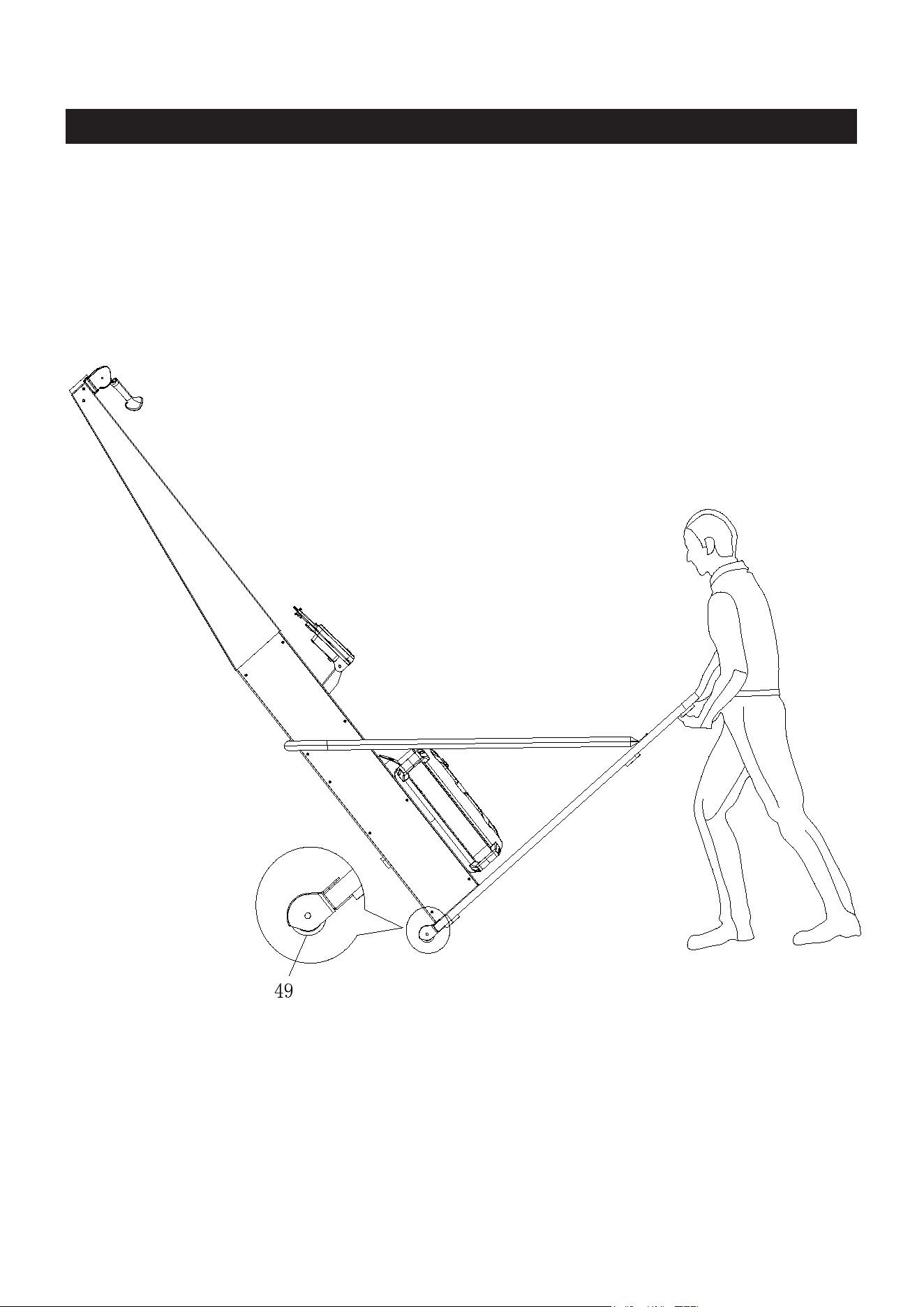
STORAGE
1.
To store the SKI TRAINER, simply keep it in a clean dry place.
2.
To avoid damage to the electronics, remove the batteries from the Console Monitor (14) before
storing the SKI TRAINER for one year or more.
3.
Move the SKI TRAINER with the Transport Wheels (49) on the Wooden Base (18). Lift one end of
Wooden Base (18) to move the SKI TRAINER. Refer to the illustration below. Do not use the U-
bar Bracket (6 ) to move the SKI TRAINER. It may ca
use danger.
22
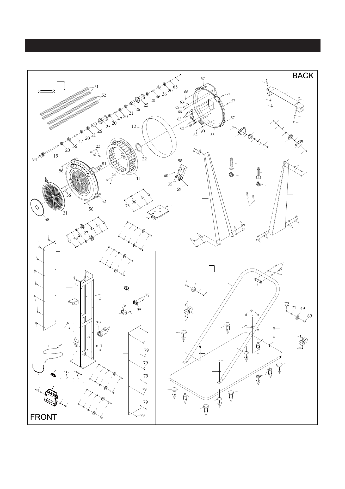
PRODUCT PARTS DRAWING
83
71
71
83
83
71
83
84
85
69
49
71
72
70
70
68
50
50
68
68
68
68
68
50
50
50
50
67
67
67
70
70
71
42
6
7
7
67
67
70
70
70
70
70
70
90
71
79
10
79
79
79
79
10
71
72
14
79
76
76
43
16
76
37
17
80
80
29
74
30
75
13
29
74
30
75
13
79
29
74
30
75
13
29
74
30
75
13
1
89
88
87
71
3
71
87
71
87
71
87 71
2
71
87
4
82
71
72
82
71
72
73
40
48
97
48
75
64
28
73
40
48
97
28
48
64
75
87
44
45
44
45
5
81
81
41
82
100
99
102
101
98
98
103
104

23
PARTS LIST
PART# DESCRIPTION QTY
1
Main Body
1
2 Left Upper Arm
1
3 Right Upper Arm
1
4
Top Bracket
1
5 EVA Single Glue For Pulley Bracket
2
6 U-bar Bracket
1
7
Transport Wheel Cover
2
10
Body Cover (Left/Right)
2
11
Fan
1
12
Perforated Steel Mesh
1
13
Console Pulley Spacer
8
14 Console Monitor
1
16
Generator
1
17 Sensor Cable
1
18
Wooden Base
1
19
Fan Axle
1
20 Bearing 6001RS
6
21 One Way Bearing (HF1212,12t)
2
22
Magnet
1
23
Balance Weight
3
24 Small Balance Weight
2
25
Cord Sleeve
2
26
Pulley Spacer
2
28 Bearing 6000ZZ
4
29
Console Pulley
8
30 Bearing 606ZZ
8
31 Damper
1
32
Upper Fan Shroud
1
33
Bottom Fan Shroud
1
35 Steel Plate
2
36
Bushing 6001
2
37 Cable Plug
2
38 Damper Cap
1
39
Pulley Cover
1

24
40
2
41
1
42
1
43
1
44
2
45
2
46
1
47
2
48
8
49
2
50
6
51
2
52
2
56
4
57
4
58
6
59
1
60
1
62
8
63
8
64
Pulley Holder
Body Upper Cover
U-bar Bracket Cushion
Generator Base
Handle
Handle Plug
Short Spacer
Long Spacer
Cord Pulley Spacer
Transport Wheel
Wooden Base Cushion
Bungee Cord
Drive Cord
Socket Head Cap Screw, M5x92mm
Hex Nut, M5
Philips Head Screw, ST4.2x6mm
Philips Head Screw, M4x45mm
Hex Nut, M4
Philips Head Screw, M6x10mm
Lock Washer, Internal Tooth M6
Flat Washer, M6
65
1
66
2
67
6
68
18
69
2
70
26
71
23
72
5
73
74
8
75
76
5
77
2
79
16
80
4
81
5
82
Flat Washer,
ø16xø6.2x1.5mm
Philips Head Screw, M6x16mm
Cushion Nut, M8
Philips Head Screw, ST4.2x16mm
Socket Head Cap Screw, M8x40mm
Philips Head Screw, ST4.2x25mm
Flat Washer, M8
Nylon Nut, M8
Button Head Cap Screw, M6x35mm
Philips Head Screw, M6x20mm
Nylon Nut, M6
Philips Head Screw, ST4.2x10mm
Philips Head Screw, ST3.0x20 mm
Philips Head Screw, M5x8mm
Hex Nut, M8
Philips Head Screw, ST4.2x16mm
Button Head Cap Screw, M8x75mm
3

25
83 Socket Head Cap Screw, M8x30mm
6
84 Button Head Cap Screw, M8x50mm
2
85 Arc washer, M8
2
87
Socket Head Cap Screw, M8x15mm
12
88 Wrench
1
89 Allen Wrench 6mm
1
90
Allen Wrench 5mm
1
94 Socket Head Cap Screw, M4x12mm
3
95
Generator Cover
1
96
Spacer (ø6.2 x ø10 x 15.5mm)
2
Aluminum Alloy Cord Pulley
2
97
Cell Phone Bracket
1
99
Bungee Cord (for Cell Phone Bracket)
1
100
Long EVA Glue (for Console Monitor)
1
101
Short EVA Glue (for Cell Phone Bracket)
1
102
Stopper Ring ø26
2
98
Socket Head Cap Screw, M6x16mm
1
103
Spring Washer, M6
1
104