
Switch Client
User Manual

Legal Informaon
©2021 Hangzhou Hikvision Digital Technology Co., Ltd. All rights reserved.
About this Manual
The Manual includes instrucons for using and managing the Product. Pictures, charts, images and
all other informaon hereinaer are for descripon and explanaon only. The informaon
contained in the Manual is subject to change, without noce, due to rmware updates or other
reasons. Please
nd the latest version of this Manual at the Hikvision website ( hps://
www.hikvision.com/ ).
Please use this Manual with the guidance and assistance of professionals trained in
supporng the
Product.
Trademarks
and other Hikvision's trademarks and logos are the properes of
Hikvision in various
jurisdicons.
Other trademarks and logos menoned are the properes of their respecve owners.
Disclaimer
TO THE MAXIMUM EXTENT PERMITTED BY APPLICABLE LAW, THIS MANUAL AND THE PRODUCT
DESCRIBED, WITH ITS HARDWARE, SOFTWARE AND FIRMWARE, ARE PROVIDED "AS IS" AND "WITH
ALL FAULTS AND ERRORS". HIKVISION MAKES NO WARRANTIES, EXPRESS OR IMPLIED, INCLUDING
WITHOUT LIMITATION, MERCHANTABILITY, SATISFACTORY QUALITY, OR FITNESS FOR A PARTICULAR
PURPOSE. THE USE OF THE PRODUCT BY YOU IS AT YOUR OWN RISK. IN NO EVENT WILL HIKVISION
BE LIABLE TO YOU FOR ANY SPECIAL, CONSEQUENTIAL, INCIDENTAL, OR INDIRECT DAMAGES,
INCLUDING, AMONG OTHERS, DAMAGES FOR LOSS OF BUSINESS PROFITS, BUSINESS
INTERRUPTION, OR LOSS OF DATA, CORRUPTION OF SYSTEMS, OR LOSS OF DOCUMENTATION,
WHETHER BASED ON BREACH OF CONTRACT, TORT (INCLUDING NEGLIGENCE), PRODUCT LIABILITY,
OR OTHERWISE, IN CONNECTION WITH THE USE OF THE PRODUCT, EVEN IF HIKVISION HAS BEEN
ADVISED OF THE POSSIBILITY OF SUCH DAMAGES OR LOSS.
YOU ACKNOWLEDGE THAT THE NATURE OF THE INTERNET PROVIDES FOR INHERENT SECURITY
RISKS, AND HIKVISION SHALL NOT TAKE ANY RESPONSIBILITIES FOR ABNORMAL OPERATION,
PRIVACY LEAKAGE OR OTHER DAMAGES RESULTING FROM CYBER-ATTACK, HACKER ATTACK, VIRUS
INFECTION, OR OTHER INTERNET SECURITY RISKS; HOWEVER, HIKVISION WILL PROVIDE TIMELY
TECHNICAL SUPPORT IF REQUIRED.
YOU AGREE TO USE THIS PRODUCT IN COMPLIANCE WITH ALL APPLICABLE LAWS, AND YOU ARE
SOLELY RESPONSIBLE FOR ENSURING THAT YOUR USE CONFORMS TO THE APPLICABLE LAW.
ESPECIALLY, YOU ARE RESPONSIBLE, FOR USING THIS PRODUCT IN A MANNER THAT DOES NOT
INFRINGE ON THE RIGHTS OF THIRD PARTIES, INCLUDING WITHOUT LIMITATION, RIGHTS OF
PUBLICITY, INTELLECTUAL PROPERTY RIGHTS, OR DATA PROTECTION AND OTHER PRIVACY RIGHTS.
YOU SHALL NOT USE THIS PRODUCT FOR ANY PROHIBITED END-USES, INCLUDING THE
DEVELOPMENT OR PRODUCTION OF WEAPONS OF MASS DESTRUCTION, THE DEVELOPMENT OR
Switch Client User Manual
i

PRODUCTION OF CHEMICAL OR BIOLOGICAL WEAPONS, ANY ACTIVITIES IN THE CONTEXT RELATED
TO ANY NUCLEAR EXPLOSIVE OR UNSAFE NUCLEAR FUEL-CYCLE, OR IN SUPPORT OF HUMAN
RIGHTS ABUSES.
IN THE EVENT OF ANY CONFLICTS BETWEEN THIS MANUAL AND THE APPLICABLE LAW, THE LATER
PREVAILS.
Switch Client User Manual
ii

Regulatory Informaon
FCC Informaon
Please take aenon that changes or modicaon not expressly approved by the party responsible
for compliance could void the user's authority to operate the equipment.
FCC compliance: This equipment has been tested and found to comply with the limits for a Class A
digital device, pursuant to part 15 of the FCC Rules. These limits are designed to provide
reasonable
protecon against harmful interference when the equipment is operated in a
commercial environment. This equipment generates, uses, and can radiate radio frequency energy
and, if not installed and used in accordance with the
instrucon manual, may cause harmful
interference to radio communicaons. Operaon of this equipment in a residenal area is likely to
cause harmful interference in which case the user will be required to correct the interference at his
own expense.
FCC Condions
This device complies with part 15 of the FCC Rules. Operaon is subject to the following two
condions:
1. This device may not cause harmful interference.
2. This device must accept any interference received, including interference that may cause
undesired
operaon.
EU Conformity Statement
This product and - if applicable - the supplied accessories too are
marked with "CE" and comply therefore with the applicable
harmonized European standards listed under the EMC Direcve 2014/
30/EU, the RoHS
Direcve 2011/65/EU.
2012/19/EU (WEEE direcve): Products marked with this symbol
cannot be disposed of as unsorted municipal waste in the European
Union. For proper recycling, return this product to your local supplier
upon the purchase of equivalent new equipment, or dispose of it at
designated collecon points. For more informaon see: hp://
www.recyclethis.info .
2006/66/EC (baery direcve): This product contains a baery that
cannot be disposed of as unsorted municipal waste in the European
Union. See the product documentaon for specic baery
informaon.
The baery is marked with this symbol, which may
include
leering to indicate cadmium (Cd), lead (Pb), or mercury (Hg).
For proper recycling, return the
baery to your supplier or to a
Switch Client User Manual
iii


Preface
Applicable Models
This manual is applicable to iVMS-4200 client of the switch.
Symbol Convenons
The symbols that may be found in this document are dened as follows.
Symbol Descripon
Danger
Indicates a hazardous situaon which, if not avoided, will or could
result in death or serious injury.
Cauon
Indicates a potenally hazardous situaon which, if not avoided, could
result in equipment damage, data loss, performance degradaon, or
unexpected results.
Note
Provides addional informaon to emphasize or supplement
important points of the main text.
Safety Instrucon
Danger
• This is a class A product and may cause radio interference in which case the user may be
required to take adequate measures.
• Ensure that your devices powered via the PoE port have their shells protected and re-proofed,
because the switches are not compliant with the Limited Power Source (LPS) standard.
• In the use of the product, you must be in strict compliance with the electrical safety
regulaons
of the naon and region.
• The socket-outlet shall be installed near the device and shall be easily accessible.
• The device must be connected to an earthed mains socket-outlet.
• Install the device according to the instrucons in this manual.
• indicates hazardous live and the external wiring connected to the terminals requires
installaon by an instructed person.
• Keep body parts away from fan blades. Disconnect the power source during servicing.
• Never place the device in an unstable
locaon. The device may fall, causing serious personal
injury or death.
• This device is not suitable for use in
locaons where children are likely to be present.
Switch Client User Manual
v

• CAUTION: Risk of explosion if the
baery is replaced by an incorrect type.
• Improper replacement of the baery with an incorrect type may defeat a safeguard (for
example, in the case of some lithium baery types).
• Do not dispose of the
baery into re or a hot oven, or mechanically crush or cut the baery,
which may result in an explosion.
• Do not leave the
baery in an extremely high temperature surrounding environment, which may
result in an explosion or the leakage of ammable liquid or gas.
• Do not subject the
baery to extremely low air pressure, which may result in an explosion or the
leakage of
ammable liquid or gas. Dispose of used baeries according to the instrucons.
Cauon
• CAUTION: Double pole/Neutral fusing.
Aer operaon of the fuse, parts of the device that
remain energized might represent a hazard during servicing.
• The device has been designed, when required, modied for connecon to an IT power
distribuon system.
• This device is suitable for
mounng on concrete or other non-combusble surface only.
• The
venlaon should not be impeded by covering the venlaon openings with items, such as
newspapers, table-cloths, curtains, etc. The openings shall never be blocked by placing the
device on a bed, sofa, rug or other similar surface.
• No naked
ame sources, such as lighted candles, should be placed on the device.
• The device shall not be exposed to dripping or splashing and that no objects lled with liquids,
such as vases, shall be placed on the device.
• Burned
ngers when handling the cover area of the device. Wait one-half hour aer switching
o before handling the parts.
• CLASS 1 LASER PRODUCT
Switch Client User Manual
vi

Contents
Chapter 1 Product Introducon .................................................................................................. 1
Chapter 2 Device Management ................................................................................................... 2
2.1 Acvate Devices ..................................................................................................................... 2
2.2 Add Devices ........................................................................................................................... 3
Chapter 3 Device Status .............................................................................................................. 5
Chapter 4 Topology Display ........................................................................................................ 7
4.1 Relate Operaons .................................................................................................................. 7
4.2 Topology Sengs ................................................................................................................... 8
Chapter 5 Network
Conguraon ............................................................................................. 10
Chapter 6 Port Conguraon .................................................................................................... 12
6.1 Aribute Conguraon ........................................................................................................ 12
6.2 Long-Range Port
Conguraon ............................................................................................ 13
6.3 VIP Port Conguraon ......................................................................................................... 14
6.4 PoE Port Conguraon ......................................................................................................... 15
Chapter 7 System
Conguraon ................................................................................................ 16
7.1 Device Informaon .............................................................................................................. 16
7.2 User Management ............................................................................................................... 16
7.3 Device Maintenance ............................................................................................................ 17
7.4 Log Management ................................................................................................................. 17
7.5 Security
Conguraon ......................................................................................................... 18
Chapter 8 Appendix .................................................................................................................. 19
8.1
Communicaon Matrix ........................................................................................................ 19
8.2 Device Command ................................................................................................................. 19
Switch Client User Manual
vii

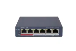
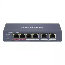
Chapter 1 Product Introducon
The switches support client management, network topology management, port management and
so on, which are suitable for small-scale LAN device access.
Note
The switch ports vary with dierent models. The actual device prevails.
Switch Client User Manual
1

Chapter 2 Device Management
The device can be congured and managed through iVMS-4200 soware, mainly including network
parameter
conguraon, port conguraon, network topology display and so on.
Note
• This chapter will
briey introduce the device management through iVMS-4200 soware. For
other funcons, please refer to User Manual of iVMS-4200 Soware.
• All pictures in this manual are for illustraon only, and the specic interface is subject to the
actual device.
2.1 Acvate Devices
For the inacve devices, you are required to create a password to acvate them before they can be
added to the soware and work properly.
Before You Start
Make sure the device to be acvated is connected to the network and is in the same network
segment with the PC running the client.
Steps
Note
This funcon should be supported by the device.
1. Enter the Device Management page.
2. Click Device tab on the top of the right panel.
3. Click Online Device to show the online device area at the
boom of the page.
The searched online devices are displayed in the list.
4. Check the device status (shown on Security Level column) and select an
inacve device.
Figure 2-1 Online Inacve Device
5. Click Acvate to open the Acvaon dialog.
6. Create a password in the password eld, and conrm the password.
Cauon
The password strength of the device can be automacally checked. We highly recommend you
change the password of your own choosing (using a minimum of 8 characters, including at least
Switch Client User Manual
2

three kinds of following categories: upper case leers, lower case leers, numbers, and special
characters) in order to increase the security of your product. And we recommend you change
your password regularly, especially in the high security system, changing the password monthly
or weekly can
beer protect your product.
Proper
conguraon of all passwords and other security sengs is the responsibility of the
installer and/or end-user.
7. Click OK to acvate the device.
2.2 Add Devices
The client provides various device adding modes including IP/domain, IP segment, cloud P2P, ISUP
protocol, and HiDDNS. The client also supports imporng mulple devices in a batch when there
are large amount of devices to be added. The secon only introduces one mode, namely, adding a
detected online device.
Steps
1. Enter the Device Management module.
2. Click Device tab on the top of the right panel.
3. Click Online Device to show the online device area.
The searched online devices are displayed in the list.
4. Select an online device in the Online Device area, and click Add to open the device adding
dialog.
Note
For the inacve device, you need to create the password for it before you can add the device
properly. For detailed steps, refer to Acvate Devices .
5. Enter the required informaon.
Name
Enter a descripve name for the device.
IP Address
Enter the device's IP address. The IP address of the device is obtained
automacally in this
adding mode.
Port
You can customize the port No. The port No. of the device is obtained automacally in this
adding mode.
User Name
By default, the user name is admin.
Password
Enter the device password.
Switch Client User Manual
3

Cauon
The password strength of the device can be automacally checked. We highly recommend
you change the password of your own choosing (using a minimum of 8 characters, including
at least three kinds of following categories: upper case leers, lower case leers, numbers,
and special characters) in order to increase the security of your product. And we recommend
you change your password regularly, especially in the high security system, changing the
password monthly or weekly can
beer protect your product.
Proper conguraon of all passwords and other security sengs is the responsibility of the
installer and/or end-user.
6. Check Synchronize Time to synchronize the device me with the PC running the client aer
adding the device to the client.
7. Click Add.
Switch Client User Manual
4

Chapter 3 Device Status
In the Device Management → Device interface, click to view the device status, port status, PoE
port status, and port
stascs.
Note
All pictures in this manual are for illustraon only, and the specic interface is subject to the actual
device.
Figure 3-1 Device Status
Device Status
You can view the device usage, device panel status and port
informaon.
Port Status
You can view the bitrate, duplex and ow control of ports.
Port Stascs
You can view the number of bytes sent or received, the number of packets sent or received,
sending or receiving rate, and peak value of sending or receiving rate.
Note
Drag the sliding bar to view all data.
PoE Port Status
Switch Client User Manual
5

You can view the enabling status and output power of dierent ports.
Switch Client User Manual
6
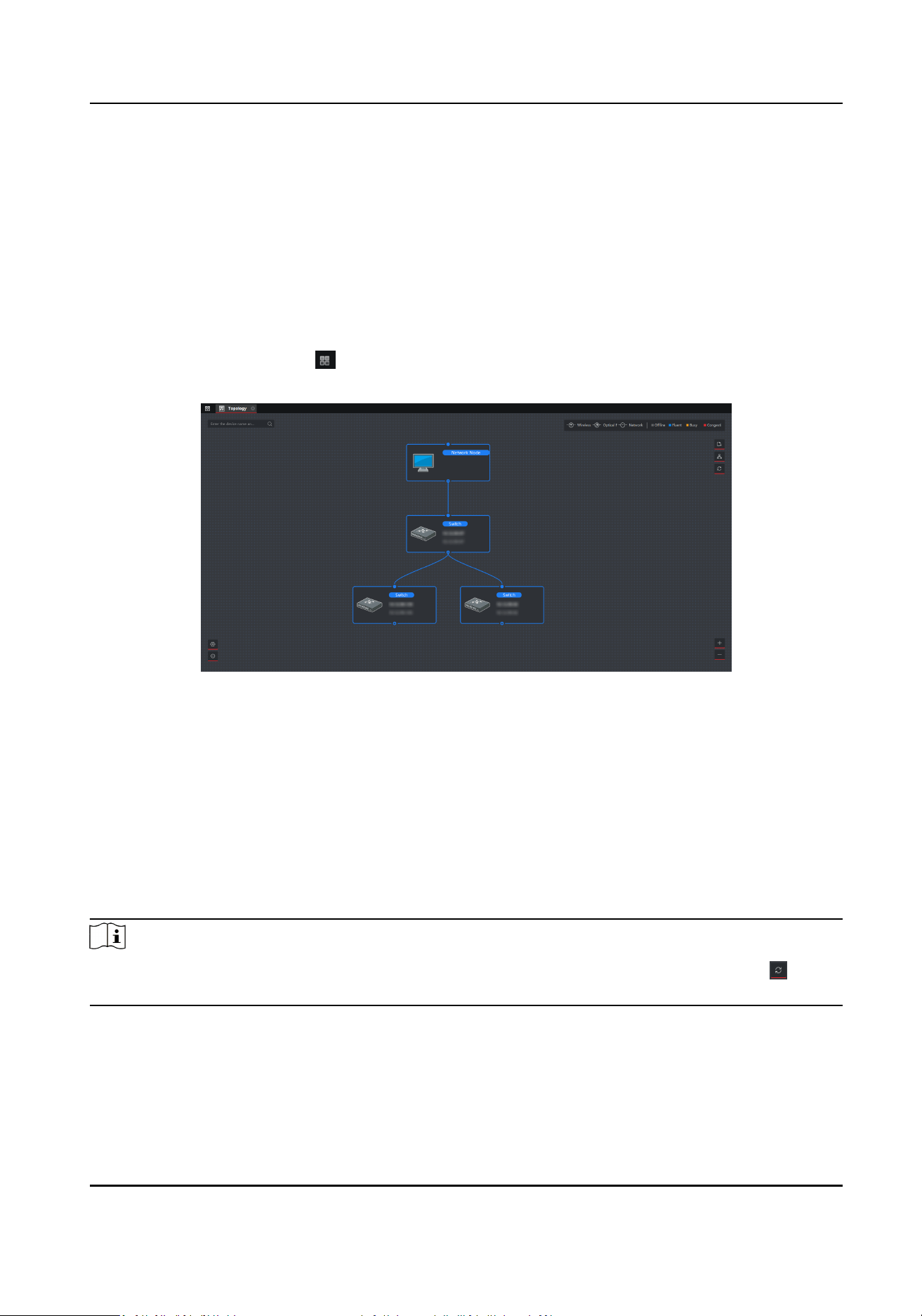
Chapter 4 Topology Display
In Topology interface, you can view the relaonships among dierent devices added and congure
the topology.
4.1 Relate Operaons
Select an added device, go to → General Applicaon → Topology to enter the topology display
interface.
Figure 4-1 Topology Display
Interface Descripon
• On the upper-le corner, you can enter another name or IP address to search the device.
• On the upper-right corner, you can view the icon of lines and the meaning of dierent colors,
select two device to show the
ash of the signal transmission between them, and export or
refresh the topology.
• On the
lower-le corner, you can do the topology sengs and view the ps.
• On the lower-right corner, you can click the icons or scroll your mouse wheel to enlarge or
narrow the topology.
Note
If you enter the topology interface for the rst me, no topology is displayed, please click to
refresh it or to get topology again.
Switch Client User Manual
7

Relate Operaons/Icons Descripon
Acons/Icons Operaon Descripon
Double click a device. Show the device type and IP, panel status, and port informaon.
Double click a line. Show transmission rate, port informaon, etc.
Right-click a device. Jump to Device Status interface. For details, see Device Status .
Show the alarm informaon and event informaon, and cancel the alarm.
Jump to Remote Conguraon interface.
Set the device as root node.
Edit the device name.
Select the path and format to export the topology.
Select IPC and current devices to show the ash of the signal transmission
between them.
4.2 Topology Sengs
Steps
1. Click on the lower-le corner to do the topology sengs.
• Set display level: 1 to 10.
• Set upstream bandwidth L1 alarm: 1% to 100%. The line will turn to yellow (busy) when the
bandwidth exceeds the threshold of L1 alarm.
• Set upstream bandwidth L2 alarm: 1% to 100%. The line will turn to red
(congeson) when
the bandwidth exceeds the threshold of L2 alarm.
2. Click OK.
Switch Client User Manual
8

Figure 4-2 Topology Sengs
Note
Aer changing the topology sengs, you need to click to view the latest topology.
Switch Client User Manual
9

Chapter 5 Network Conguraon
In Network interface, you can congure network parameters as needed.
Basic Sengs
Go to → Network → General to congure NIC type, IPv4 address, subnet mask, gateway
address, MAC address, and device port.
Figure 5-1 Network Conguraon
Note
Aer the IPv4 address is reset, the device IP may not be in the same network segment as the
computer IP of the client, so it cannot be congured and managed. It is recommended to use the
SADP tool to plan the IP address of the device when the device is acvated for the rst me.
Advanced Sengs
Go to → Network → Advanced Sengs to congure DNS IP address.
DNS Server address of your own computer or public address on the internet are both available.
Figure 5-2 Advanced Sengs
Switch Client User Manual
10
Note
• DNS auto-obtain is available only when you check Auto-obtain in Network → General .
• It is recommended to
congure both DNS1 and DNS2 address to prevent that one of the
addresses is invalid.
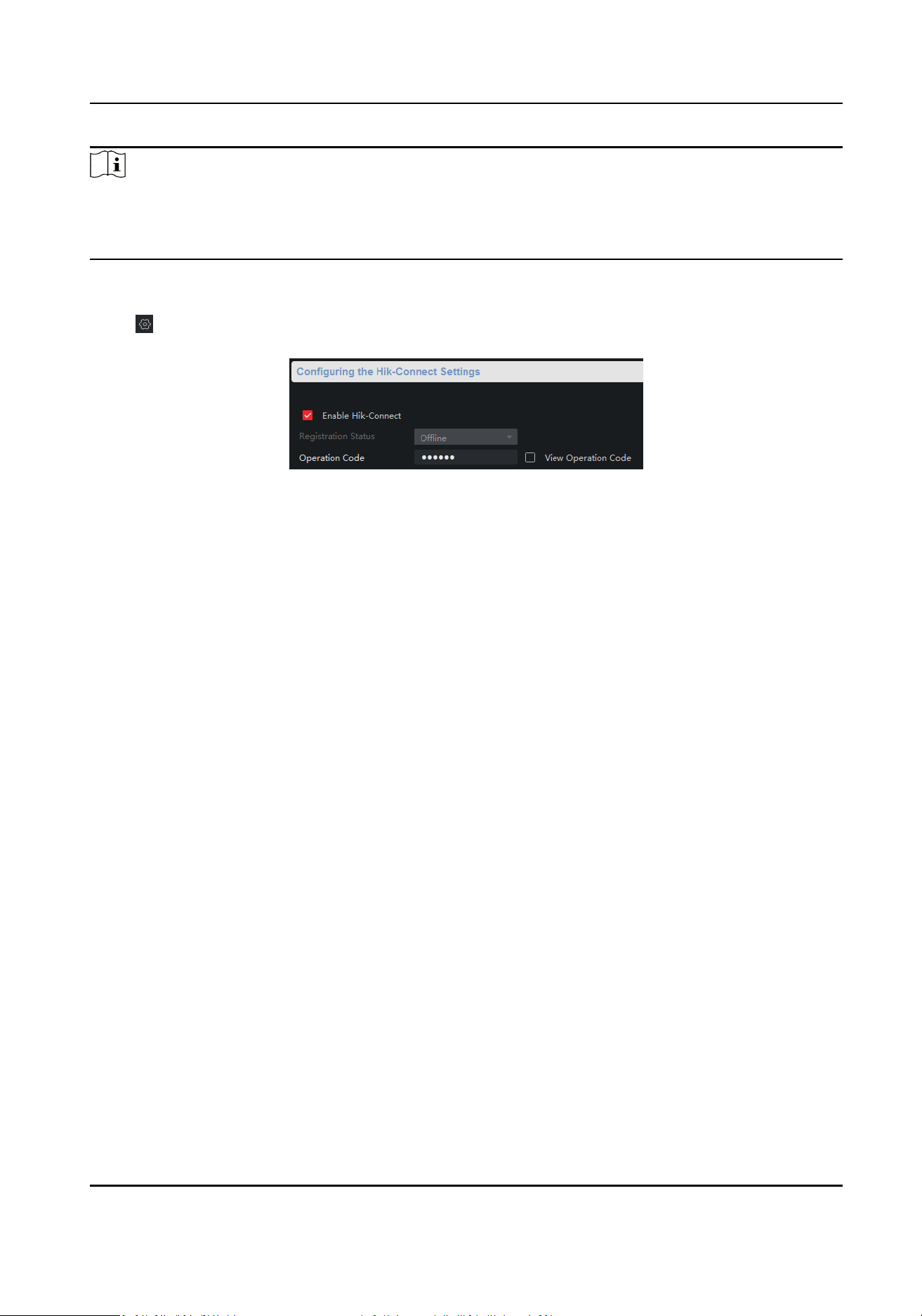
Hik-Connect Sengs
Go to → Network → Conguring the Hik-Connect Sengs to enable Hik-Connect to upload data
to the Hik-Connect.
Figure 5-3 Hik-Connect Sengs
1. Check Enable Hik-Connect.
2. Enter Operaon Code.
3. Click Save.
Switch Client User Manual
11

Chapter 6 Port Conguraon
Select → Port Conguraon to enter the interface.
Note
• You can take your
conguraon into eect by clicking OK. But to prevent invalid conguraon
caused by device power o, you can go to → Global Save → Save to save all your
conguraons.
• Dierent devices have dierent funcons, so the actual interface shall prevail.
6.1 Aribute Conguraon
The basic parameters can inuence the working status of ports. Congure the bitrate, duplex, and
ow control, and enable or disable ports according to the actual situaons in the Aribute
Conguraon interface.
Figure 6-1 Aribute Conguraon
Switch Client User Manual
12

Bitrate
The data transmission rate of the port. The rate includes auto, 10 Mbps, 100 Mbps, and 1000
Mpbs. The default is Auto
Negoaon. The congurable rate varies with dierent ports.
Duplex
The duplex mode of the port. Only Auto Negoaon is available for the current version.
Flow Control
Enabling the ow control can prevent data loss in data transmission. The default is Enable.
Enable
Enable or disable the port link.
Aer you disable the port link, the data of the port stops
transmission, but the power is supplied for other devices.
Note
The rate, duplex, and ow control conguraon of all ports must be the same in the aggregaon
group .
6.2 Long-Range Port Conguraon
When the long-range mode is enabled, the transmission distance of the port can reach 300 meters,
and the rate is 10 Mbps. When the long-range mode is disabled, the rate is restored to auto.
Switch Client User Manual
13
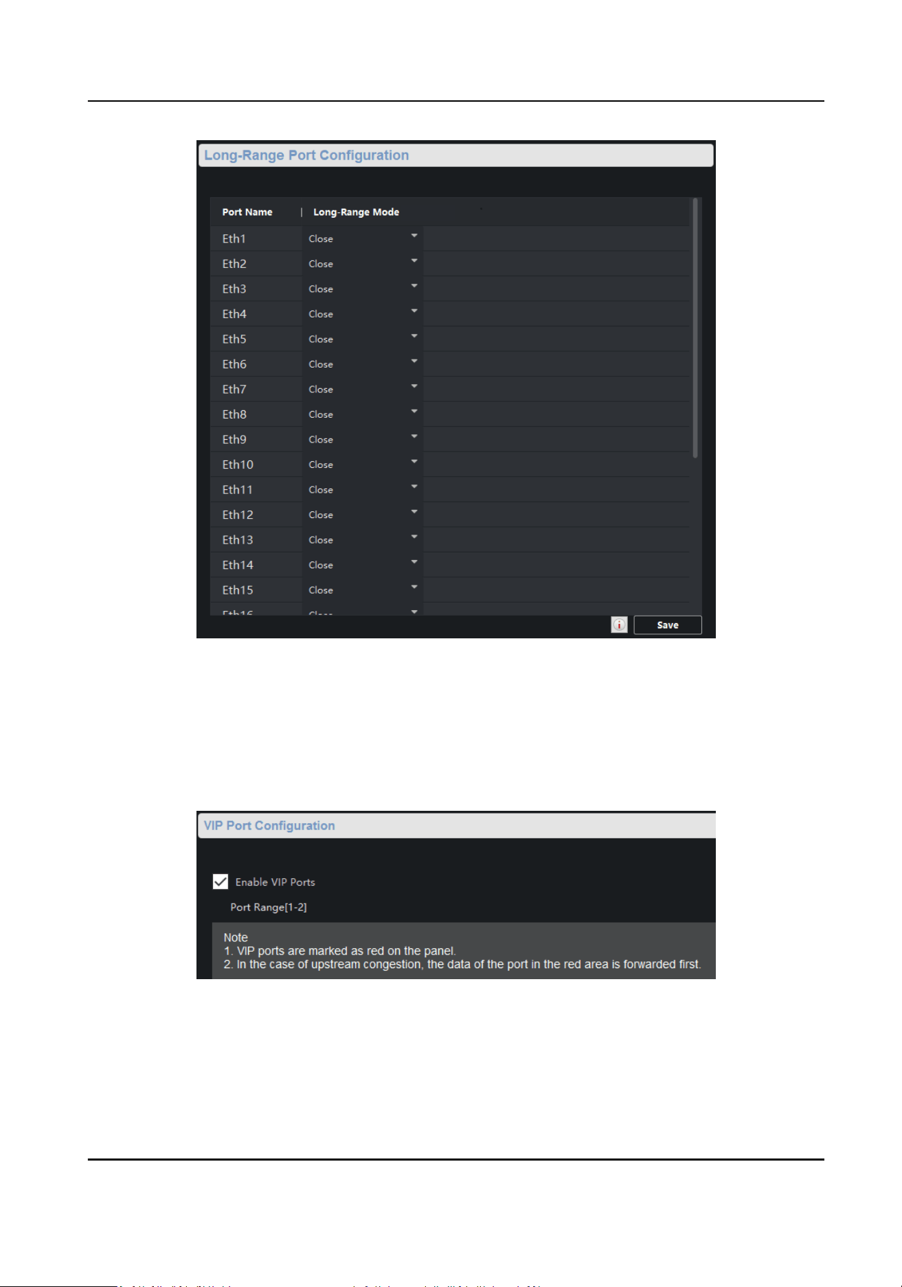
Figure 6-2 Long-Range Conguraon
6.3 VIP Port
Conguraon
VIP ports refer to high priority ports, which is idened by the red area on the device. In the case
of uplink congeson, the data for the ports in this area is transmied rst.
Figure 6-3 VIP Port Conguraon
Switch Client User Manual
14

6.4 PoE Port Conguraon
You can enable PoE to supply power for the powered devices (PDs).
Note
Enabling or disabling PoE has no inuences on data transmission of the port.
Figure 6-4 PoE Port Conguraon
Switch Client User Manual
15
Chapter 7 System Conguraon
7.1 Device Informaon
Select → System → Device Informaon to view the device informaon including the device
name, device model, port No., and port informaon.
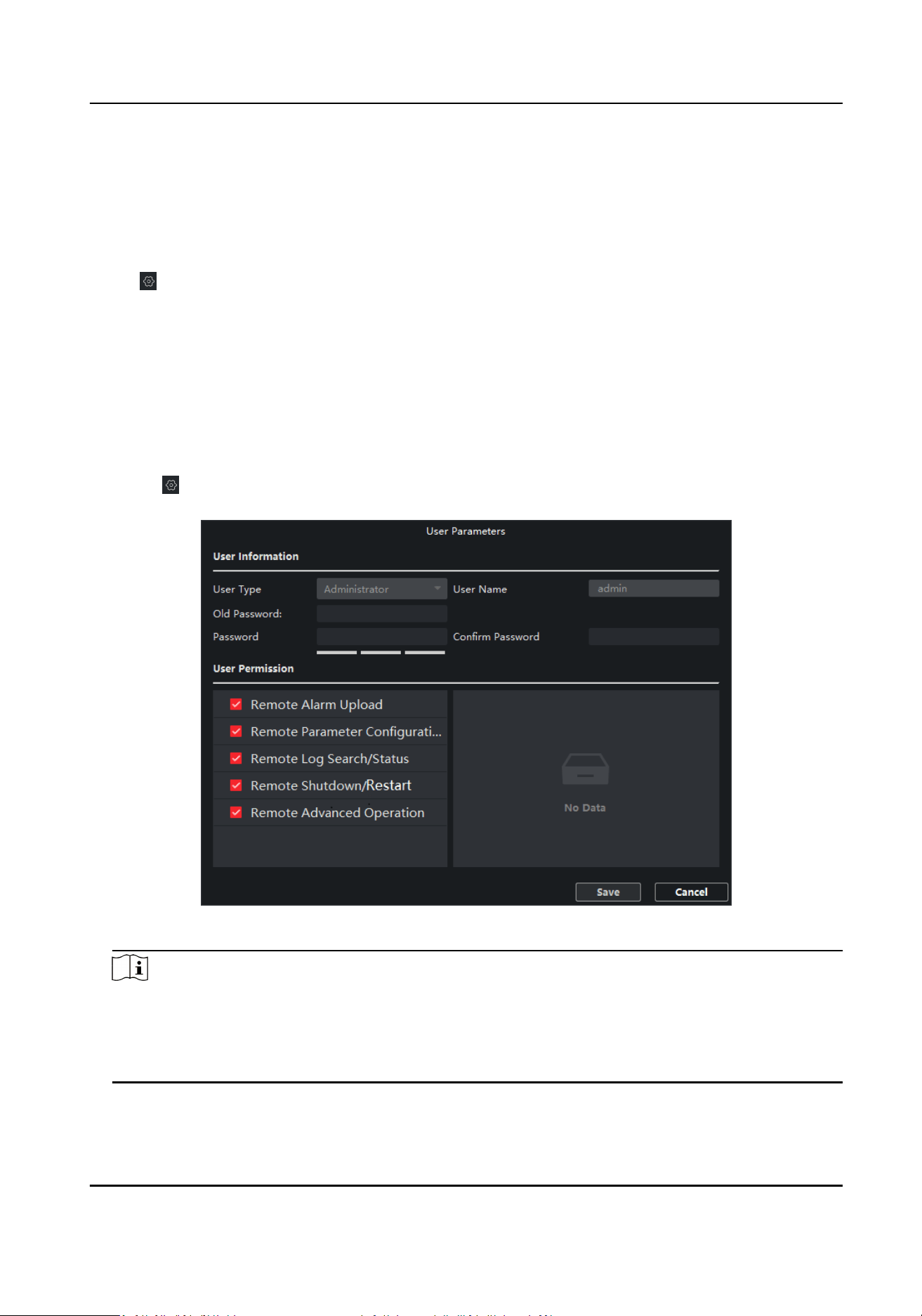
7.2 User Management
The device only supports one admin user. Users cannot be added or deleted. You can only edit the
passwords, IP addresses and permissions of the user.
Steps
1. Select
→ System → User .
2. Click Edit or double-click the user to edit the password, IP address or permission of the user.
Figure 7-1 User Parameters
Note
8 to 16 characters is allowed for the password, including at least 2 of the following types: digits,
lower-case leers, upper-case leers, and special characters. The password strength of the
device can be automacally checked. We highly recommend you change your password
regularly in order to increase the security of your product.
Switch Client User Manual
16

7.3 Device Maintenance
You can restart the device, restore the defaults, upload the upgrade le to upgrade your device.
Steps
1. Select
→ System → System Maintenance .
2. Select
funcon buon to realize dierent funcons.
• Reboot: Click Reboot to remotely restart the device.
•
Restore Default
Sengs: Except network conguraon and user parameters, all of the other
parameters are restored to the default sengs.
• Restore All: All parameters are restored to the default sengs. Aer restoraon, the device
needs to be
acvated again.
• Import Conguraon File: Select the conguraon le, and enter the password for le
export. Aer import, the devices will be restarted automacally.
• Export Conguraon File: Set and conrm the password for le export, and click OK. Select a
storage path, and click Save.
• Click
to select the upgrade le, and click Upgrade. The upgrading progress is shown below.
Note
If upgrading failed or the device cannot funcon, please contact our technical engineers.
7.4 Log Management
System operaon logs can be searched and exported for backup.
Steps
1. Select → System → Log Query .
2. Set search
condions.
Search Mode
By Type, By Time, By Time&Type or All can be selected.
Major Type
Operaon, Event, and All can be selected. If you select the search mode as by me, the
major type cannot be set.
Minor Type
Minor type is
dierent under dierent major type. If you select the search mode as by me,
the major type cannot be set.
Start Time
It refers to the start me for the logs. If you select the search mode as by type, the major
type cannot be set.
End Time
Switch Client User Manual
17

It refers to the end me for the logs. If you select the search mode as by type, the major type
cannot be set.
3. Click Search.
4. Click Backup, and select a backup path.
5.
Click Backup.
7.5 Security Conguraon
If the IP is locked because you enter a wrong password, the admin user can log in to the client at
the PC (the IP is not locked) and enter the Security interface to unlock the locked IP.
Steps
Note
If you need to unlock it immediately, you can contact the admin user.
1. Select → System → Security .
2. Unlock the IPs.
• Click unlock icon to unlock single IP.
• Click Unlock All to unlock all of the IPs.
Note
• If the admin user is locked, you need to change the IP to log in admin again and unlock the
locked IP.
• Up to 5 trials of password are allowed for ordinary users, and 7 for the admin user.
Switch Client User Manual
18

Chapter 8 Appendix
8.1 Communicaon Matrix
Please scan the QR code below to view the communicaon matrix document.
Figure 8-1 Communicaon Matrix
8.2 Device Command
Please scan the QR code below to view the device command document.
Figure 8-2 Device Command
Switch Client User Manual
19

UD23050B