

Installation manual 2N® IP Verso 2.0
2 / 213
•
•
•
•
•
•
•
•
•
•
•
•
•
•
•
•
•
•
•
•
•
•
•
•
•
•
•
•
•
•
•
•
•
•
•
•
•
•
•
•
Content:
1. Product Overview
1.1 Components and Associated Products
1.2 Terms and Symbols
2. Description and Installation
2.1 Before You Start
2.2 Mechanical Installation
2.2.1 Flush Mounting
2.2.1.1 One Module Box
2.2.1.2 Two Module Box
2.2.1.3 More Two Module Boxes
2.2.1.4 Three Module Box
2.2.1.5 More Three Module Boxes
2.2.2 Surface Mounting
2.2.2.1 One Module Box
2.2.2.2 Two Module Box
2.2.2.3 More Two Module Boxes
2.2.2.4 Three Module Box
2.2.2.5 More Three Module Boxes
2.2.3 Example of Mounting Plate Installation
2.2.4 Tamper and I/O Modules
2.2.5 Module Dimensions
2.3 Electric Installation
2.3.1 Overvoltage Protection
2.4 Extending Module Connection
2.5 Completion
3. Function and Use
3.1 Configuration
3.1.1 2N® IP Verso LAN Location via 2N® Network Scanner
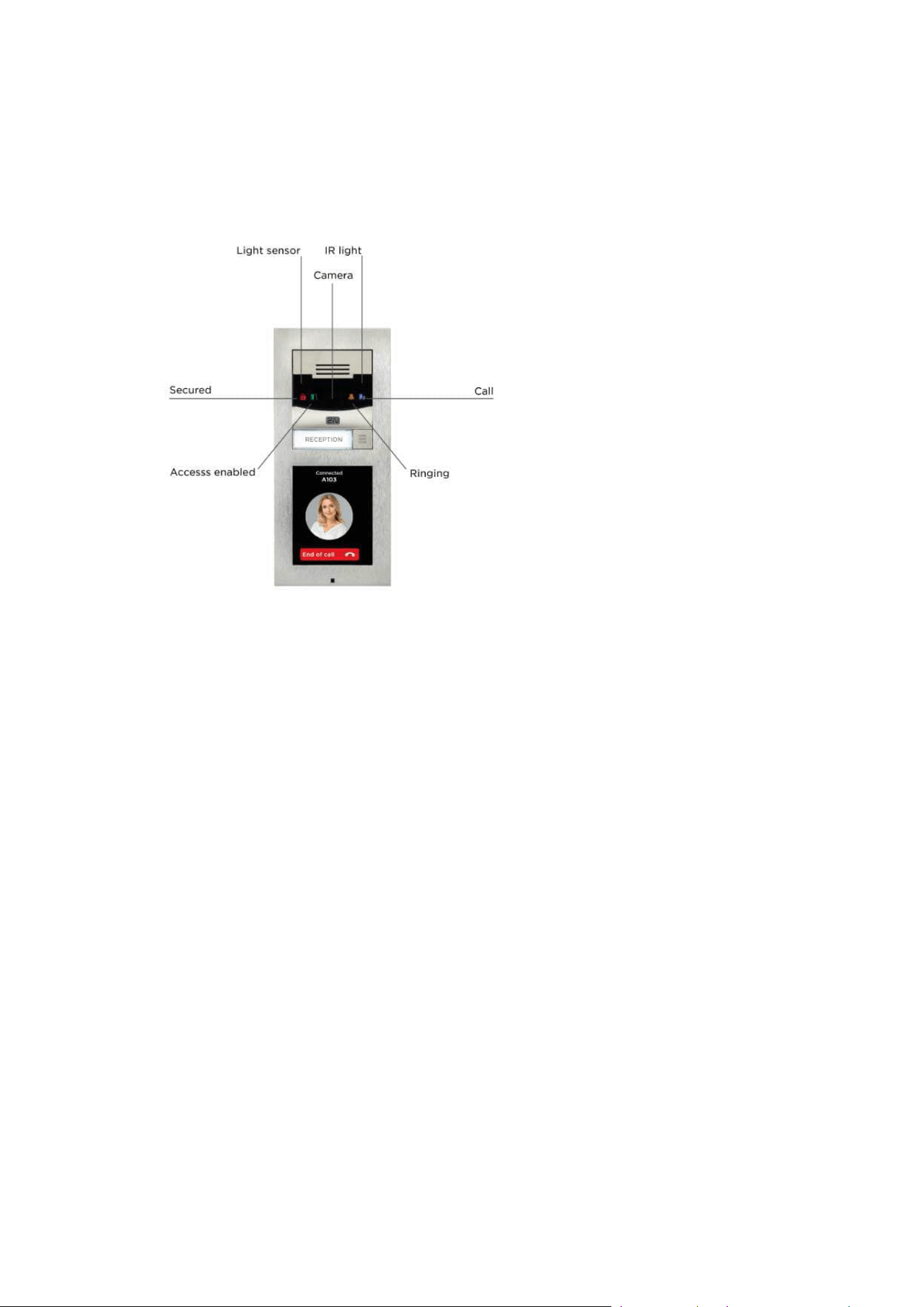
3.2 Intercom Control as Viewed by External User
3.3 Touch Display Intercom Control As Viewed by External User
3.4 Intercom Control as Viewed by Internal User
3.5 Maintenance
3.6 Downloads
4. Technical Parameters
4.1 General drawings
5. Supplementary Information
5.1 Troubleshooting
5.2 Directives, Laws and Regulations
5.3 Other Countries' Legislation
5.4 General Instructions and Cautions

Installation manual 2N® IP Verso 2.0
3 / 213
•
•
1. Product Overview
Here is what you can find in this section:
1.1 Components and Associated Products
1.2 Terms and Symbols
Basic Features
2N
®
IP Verso 2.0is an elegant and reliable intercom equipped with lots of useful functions.
Thanks to SIP support and compatibility with major brands of PBX manufacturers, it can benefit
from using VoIP networks.2N
®
IP Verso 2.0can be used as a door or special purpose intercom
for office buildings, residential areas and other applications.
2N
®
IP Verso 2.0is a modular system: the user determines its configuration according to the
needs of the particular installation. Unlike other intercoms,
2N
®
IP Verso 2.0is not delivered as a compact unit. After choosing the installation mode and
particular modules, the user gets separate parts to be assembled using the plug&play
connections. This approach allows for unique individual combinations and also leaves space for
adding of additional modules later on.
Wide angle Full HD camera– allows the tenant to see the calling person on his or her
videophone or PC screen in high resolution. The camera itself is hidden behind a darkened glass,
so it is not visible. The intercom is equipped with night vision, which automatically selects the
night/day mode according to light.
Quick dial buttons– there are 146 quick dial buttons in total in multiple button modules. For
each button, up to three separate phone numbers plus substitute users can be defined, which
ensures that the called user is reached whenever needed. The buttons are backlit with a clear
mechanical response. The nametag surface is scratch resistant.
Keypad– is a keypad module that allows the user to use the intercom as a code lock and dial a
phone number or phonebook position of the called user.
RFID card reader– thecard reader module brings the access control functionality according to
the RFID card or keyfob. With the advanced features, other functions can be RFID card controlled
too.
Electric lock control– as part of the access system, the electrical lock can be controlled by a
code entered on the keypad or the called phone, with the RFID card, via a PC application, etc.
When necessary, more electrical outputs can be added. Numerous parameters allow for a wide
spectrum of applications.
Robustness–2N
®
IP Verso 2.0is designed as a vandal resistant intercom, which withstands
mechanical or weather conditions with no need to purchase extra accessories.
Audio quality– using the automatic echo cancelling system, full duplex communication is
available at any time.

Installation manual 2N® IP Verso 2.0
4 / 213
•
•
•
•
•
•
•
•
•
•
•
•
•
•
•
•
•
•
•
•
•
•
•
The installation of2N
®
IP Verso 2.0is very easy, all you have to do is assemble the required
parts and modules and attach the network cable. The modules are plug&play, so there is no
need to configure them manually. The intercom can be supplied from a 12 V DC power source, or
using a PoE switch.
Use your PC with any internet browser to configure2N
®
IP Verso 2.0orapply the2N
®
Access
Commanderto configure extensive installations of multiple intercoms.
Advantages of Use
Elegant design
Weather resistant
Various modes of installation (flush, surface, plasterboard)
Sensitive microphone and loud speaker
Both-way audio communication – acoustic echo cancellation
Integrated colour HD camera with wide-angle lense and hidden night vision
Selectable number of quick dial buttons with nametags and backlight
Optional numeric keypad with backlight
Option to have multiple modules of the same kind – for example, card reader for both
entering and leaving the building
Integrated switches of electric locks with wide setting options
Optional integrated RFID card reader module
PoE or 12 V DC power supply
Configuration using web interface or dedicated PC application
VoIP standard SIP 2.0 support
10 000 Phone Book positions
20 user time profiles
Video codecs (H.264, MJPEG),
Audio codecs (G.711, G.722, G.729, L16/16 kHz),
HTTP server for configuration
SNTP client for time synchronisation
RTSP server for audio and video streaming, ONVIF compatible
SMTP client for email sending, Picture to Email feature
TFTP/HTTP client for automated firmware and configurationupgrade and update
Installation manual 2N® IP Verso 2.0
5 / 213
•
•
•
•
•
•
1.1 Components and Associated Products
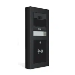
Main Units
Part No. 9155211C
Full HD camera
Make sure that one main unit at least is included in the installation.
The main unit installation requires two frame/box positions; the
other position, however, is left for additional module installation.
Part No.
9155211CB
Full HD camera
Black version
Make sure that one main unit at least is included in the installation.
The main unit installation requires two frame/box positions; the
other position, however, is left for additional module installation.
We do not recommend that the device should be installed where
exposed to direct sunlight.
•
•
•
Make sure that one main unit at least is included in the installation.
The main unit installation requires two frame / box positions, however, the other
position remains at disposal for another module installation.
One blind module is supplied with the main unit.

Installation manual 2N® IP Verso 2.0
6 / 213
•
•
•
•
•
•
Frames
2N Part
No.9155011
Axis Part No.
01278-001
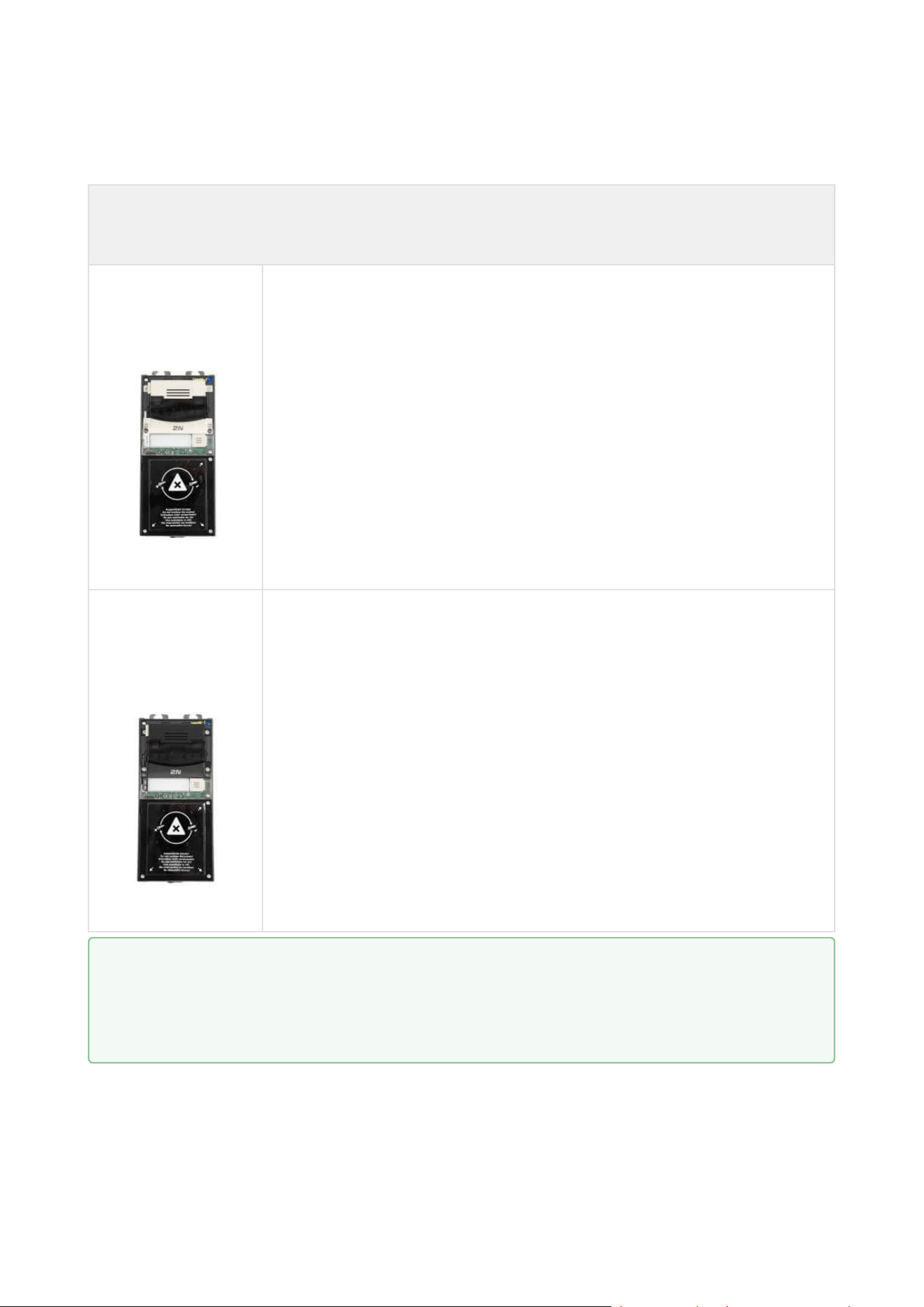
Flush mounting frame
1 module
Covering frame for the 1-module brick/plasterboard flush
mounting box. The 1-module frame is used when another module
is added to the existing installation or when the module is
mounted to an extended interconnecting cable for an outgoing
reader, for example. Remember to order the frame when you order
a 1-module flush mounting box, Part No. 9155014.
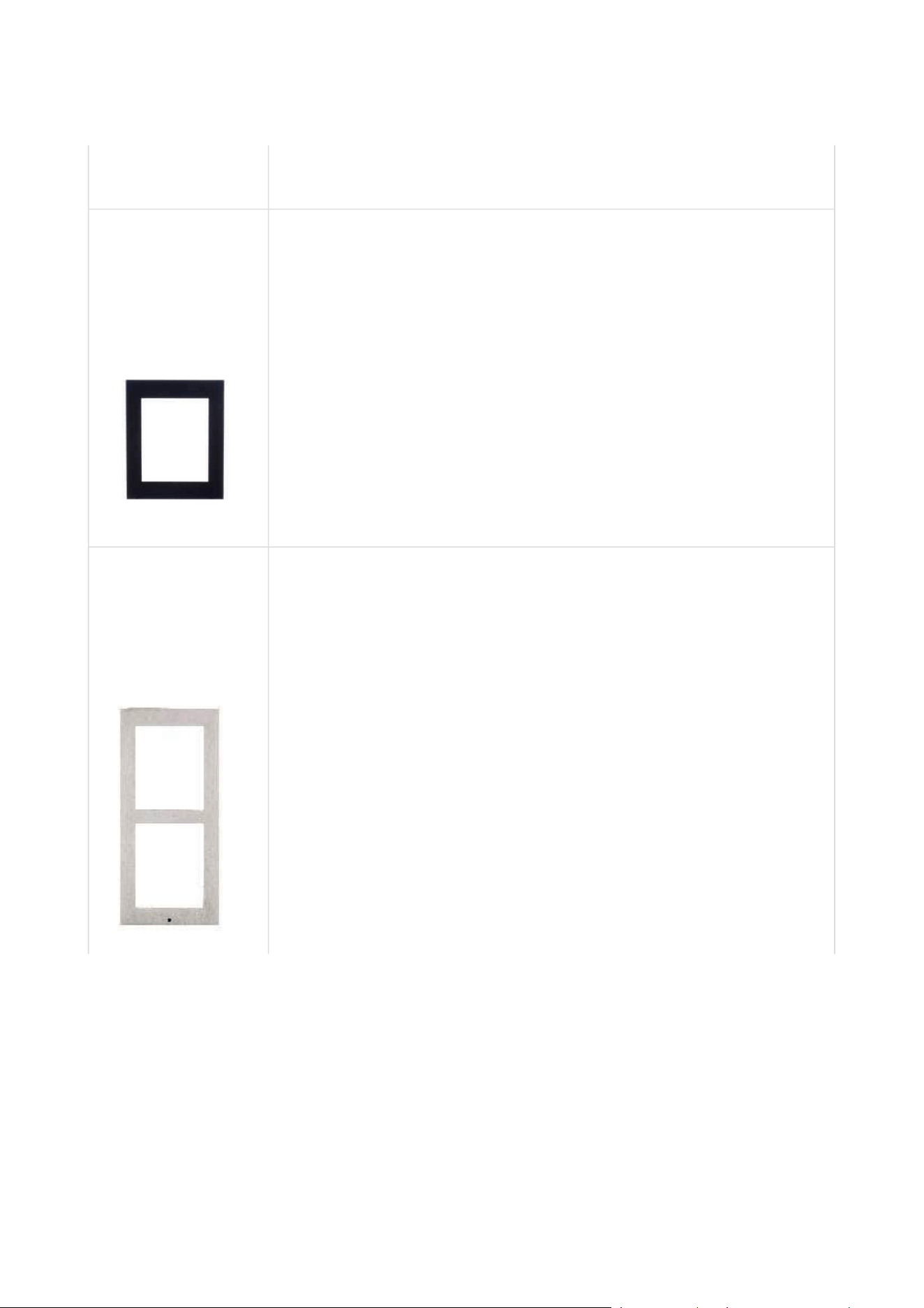
2N Part
No.9155011B
Axis Part No.
01279-001
Flush mounting frame
1 module
Covering frame for the 1-module brick/plasterboard flush
mounting box. The 1-module frame is used when another module
is added to the existing installation or when the module is
mounted to an extended interconnecting cable for an outgoing
reader, for example. Remember to order the frame when you order
a 1-module flush mounting box, Part No. 9155014.
Installation manual 2N® IP Verso 2.0
7 / 213
•
•
•
•
•
•
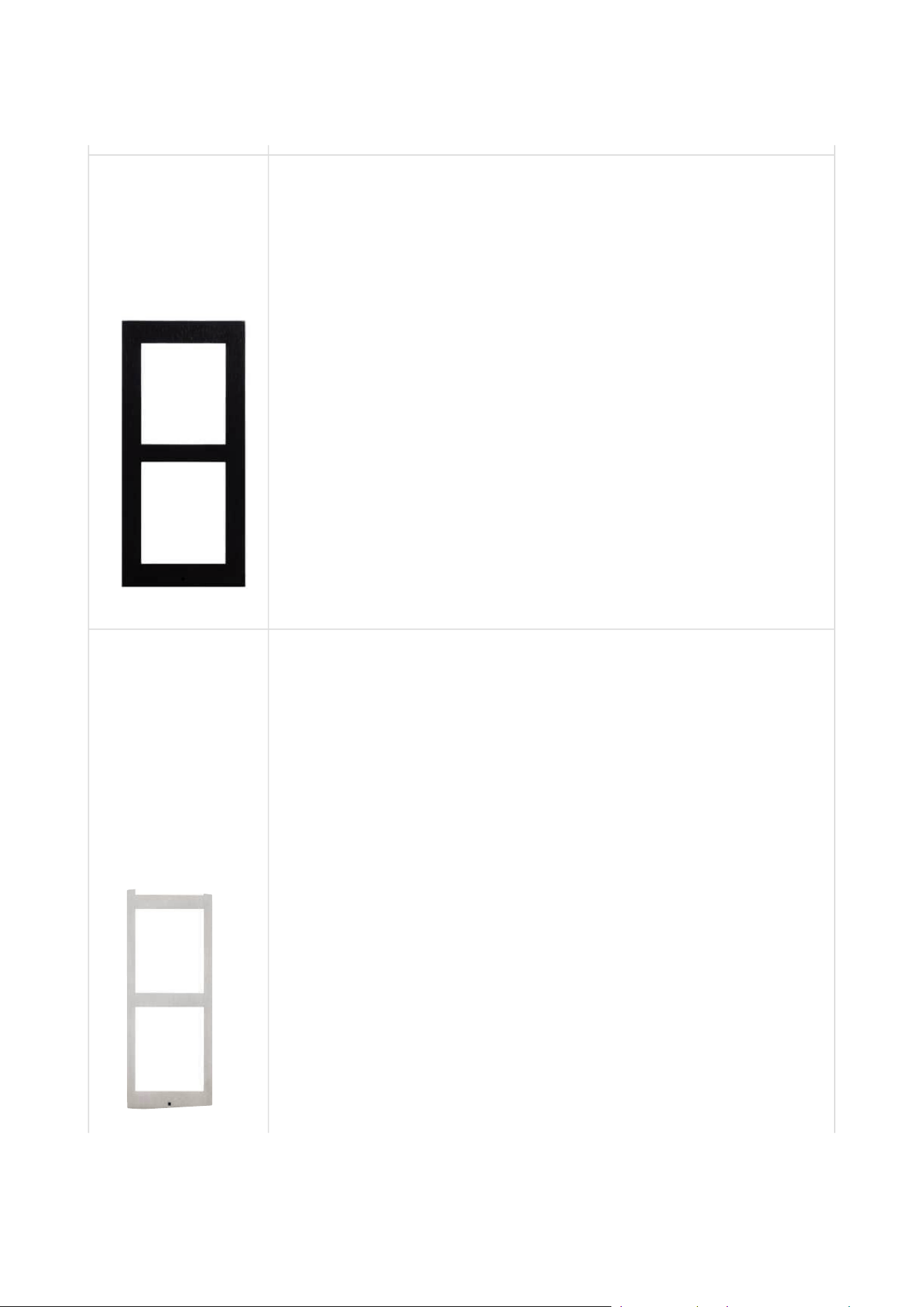
2N Part
No.9155012
Axis Part No.
01281-001
Flush mounting frame
2 modules
Covering frame for the 2-module brick/plasterboard flush
mounting box. Remember to order the frame when you order a 2-
module flush mounting box, Part No. 9155015.
2N Part
No.9155012B
Axis Part No.
01282-001
Flush mounting frame
2 modules
Covering framefor the 2-module brick/plasterboard flush
mounting box. Remember to order the frame when you order a 2-
module flush mounting box, Part No. 9155015.

Installation manual 2N® IP Verso 2.0
8 / 213
•
•
•
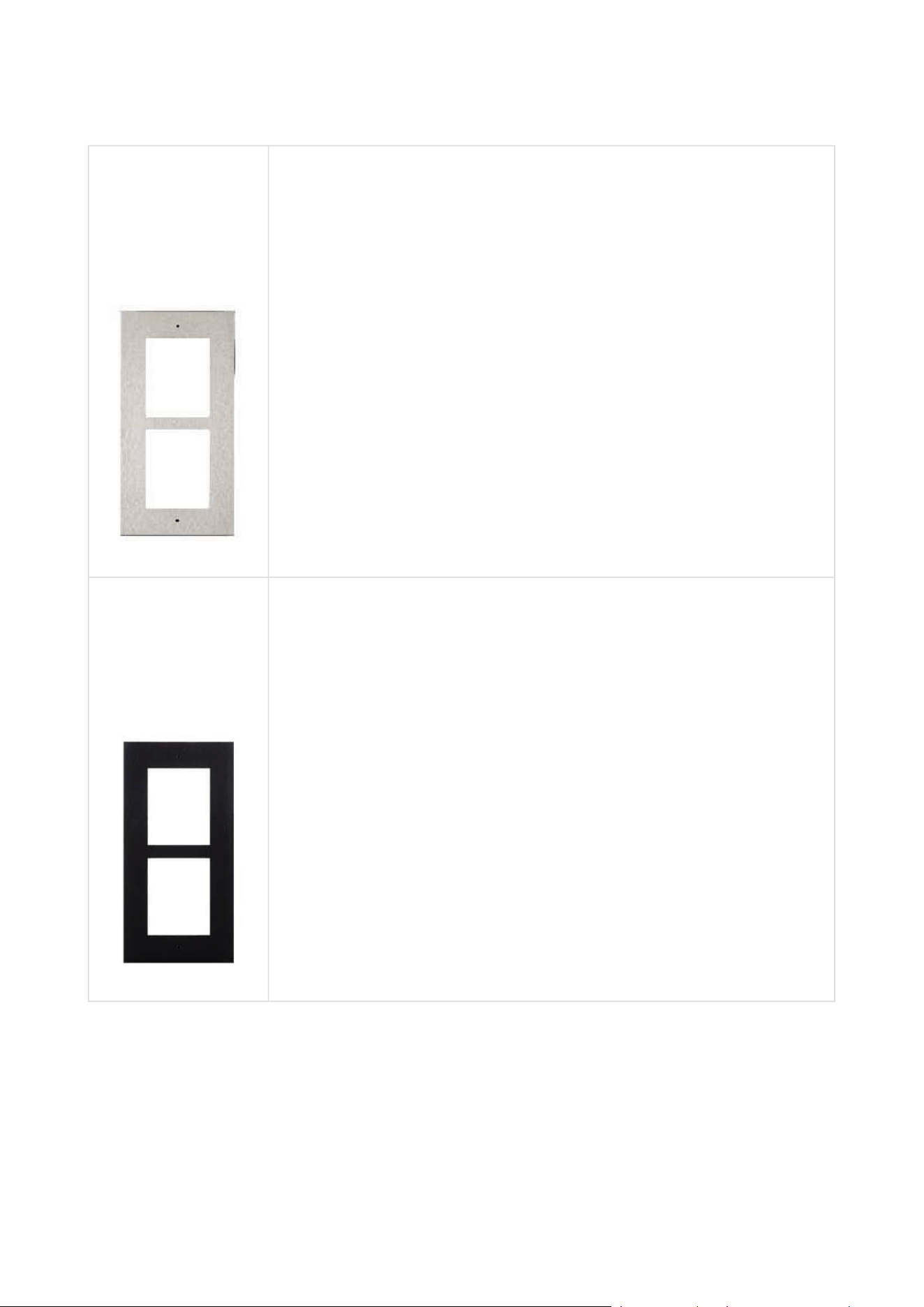
2N Part
No.9155013
Axis Part No.
01282-001
Flush mounting frame
3 modules
Covering frame for the 3-module brick/plasterboard flush
mounting box.Remember to order the frame when you order a 3-
module flush mounting box, Part No. 9155016.
Installation manual 2N® IP Verso 2.0
9 / 213
•
•
•
•
•
•
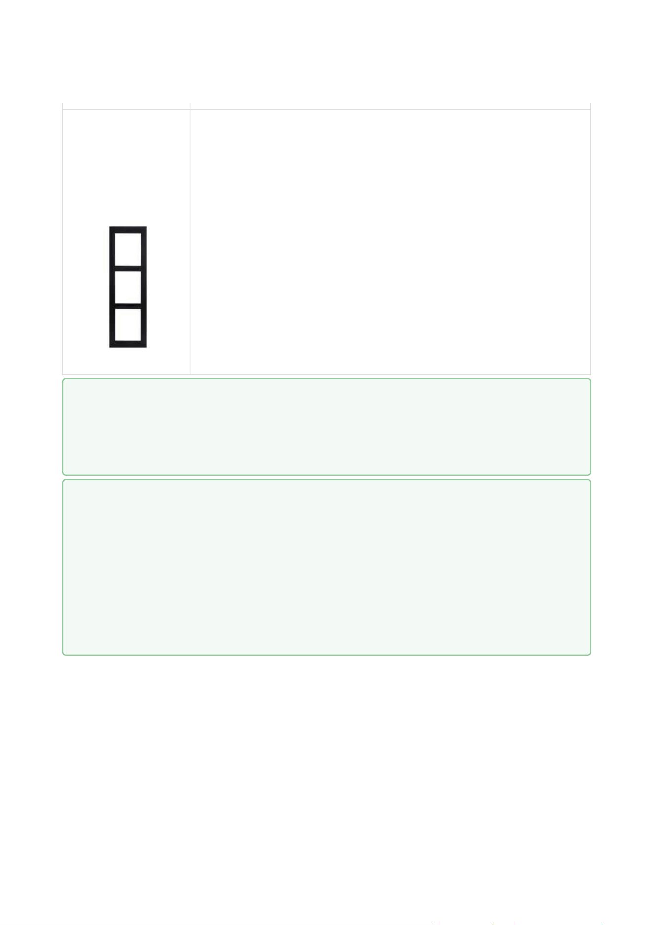
2N Part
No.9155013B
Axis Part No.
01283-001
Flush mounting frame
3 modules
Covering frame for the 3-module brick/plasterboard flush
mounting box.Remember to order the frame when you order a 3-
module flush mounting box, Part No. 9155016.
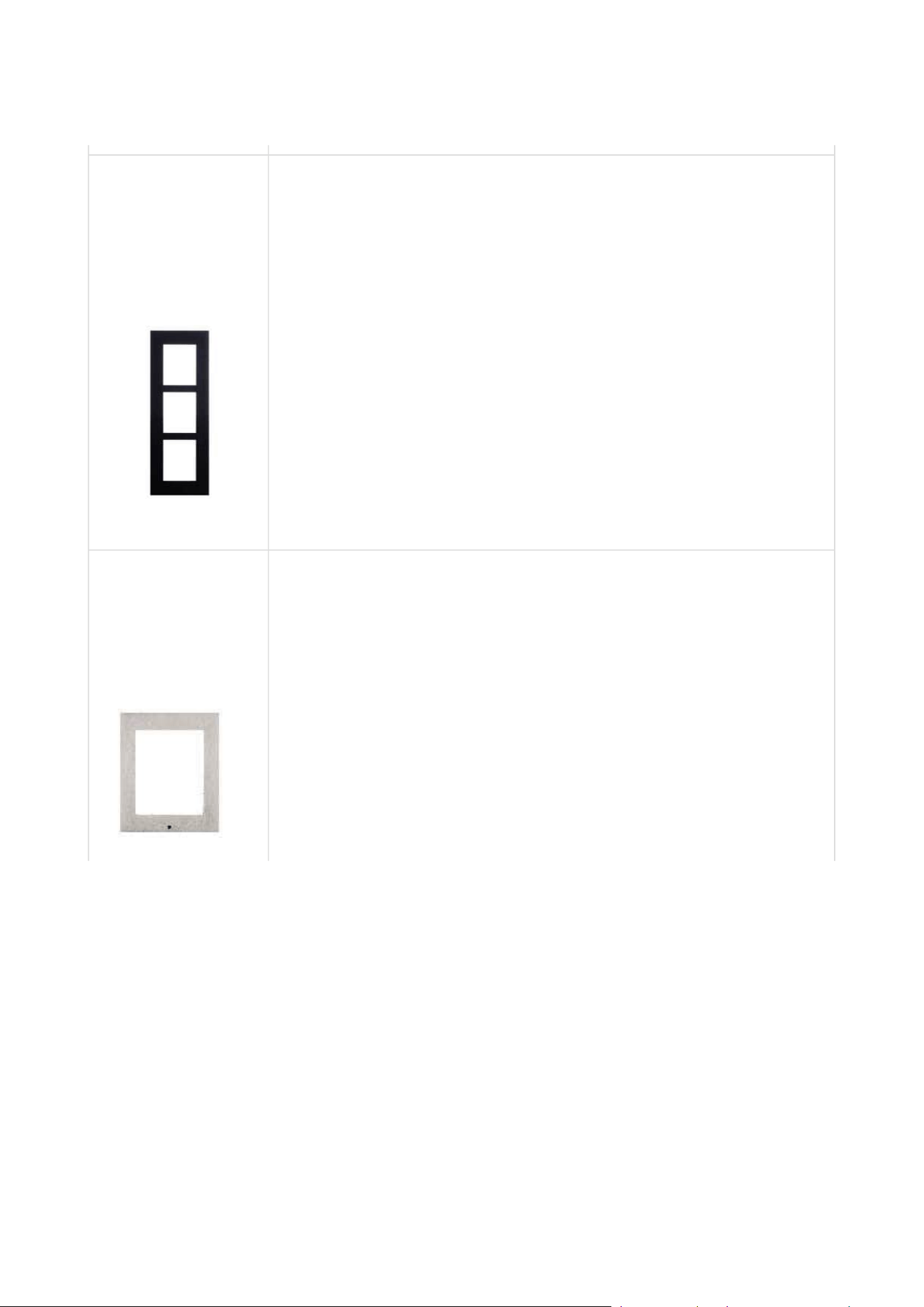
2N Part
No.9155021
Axis Part No.
01287-001
Surface mounting frame
1 module
The 1-module frame is used when another module is added to the
existing installation or when the module is mounted to an
extended interconnecting cable for an outgoing reader, for
example.
Installation manual 2N® IP Verso 2.0
10 / 213
•
•
•
•
•
2N Part
No.9155021B
Axis Part No.
01288-001
Surface mounting frame
1 module
The 1-module frame is used when another module is added to the
existing installation or when the module is mounted to an
extended interconnecting cable for an outgoing reader, for
example.
2N Part
No.9155022
Axis Part No.
01289-001
Surface mounting box
2 modules
Installation manual 2N® IP Verso 2.0
11 / 213
•
•
•
•
2N Part
No.9155022B
Axis Part No.
01290-001
Surface mounting box
2 modules
2N Part
No.9155023
Axis Part No.
01291-001
Surface mounting box
3 modules
Installation manual 2N® IP Verso 2.0
12 / 213
•
•
2N Part
No.9155023B
Axis Part No.
01292-001
Surface mounting box
3 modules
•
Tip
The 1-module frame is used when another module is added to the existing
installation or when the module is mounted to an extended interconnecting cable
for an outgoing reader, for example.
•
•
•
•
Tip
Be sure to order the covering frame for the flush or plasterboard mounting box
together with the flush mounting box.
1-module frame (Part No. 9155011) – 1-module flush mounting box (Part No.
9155014)
2-module frame (Part No. 9155012) – 2-module flush mounting box (Part No.
9155015)
3-module frame (Part No. 9155013) – 3-module flush mounting box (Part No.
9155016)
Installation manual 2N® IP Verso 2.0
13 / 213
•
•
•
•
•
•
Extending Modules
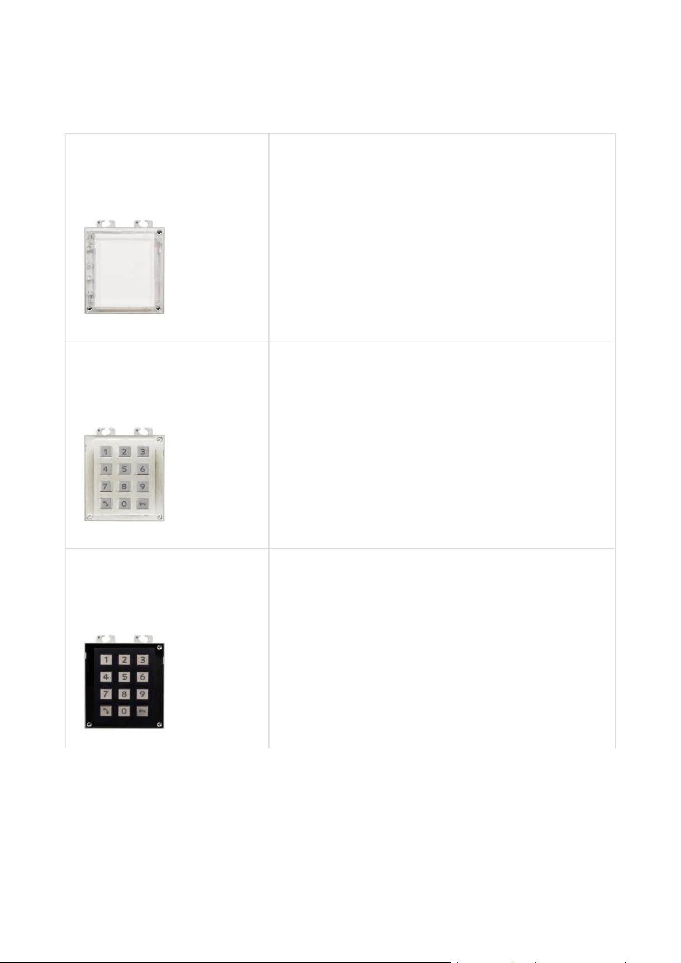
2N Part No.9155030
Axis Part. No. 01252-001
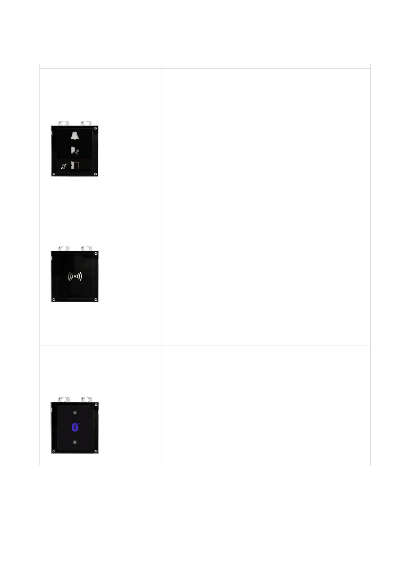
2N IP Verso 2.0 – Info panel
The Infopanel module helps you place such
information into the intercom installation as house
number, opening hours and similar data. The
Infopanel backlight is software controlled.
2N Part No.9155031
Axis Part No. 01253-001
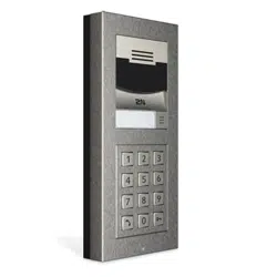
2N IP Verso 2.0 – Keypad
The numeric keypad module helps you dial users via
their phonebook positions or phone numbers, control
the lock and use other code-accessible functions. The
keypad digits and symbols are backlit.
2N Part No.9155031B
Axis Part No. 01254-001
2N IP Verso 2.0 – Keypad
The numeric keypad module helps you dial users via
their phonebook positions or phone numbers, control
the lock and use other code-accessible functions. The
keypad digits and symbols are backlit.
Installation manual 2N® IP Verso 2.0
14 / 213
•
•
•
•
•
•
•
•
•
•
•
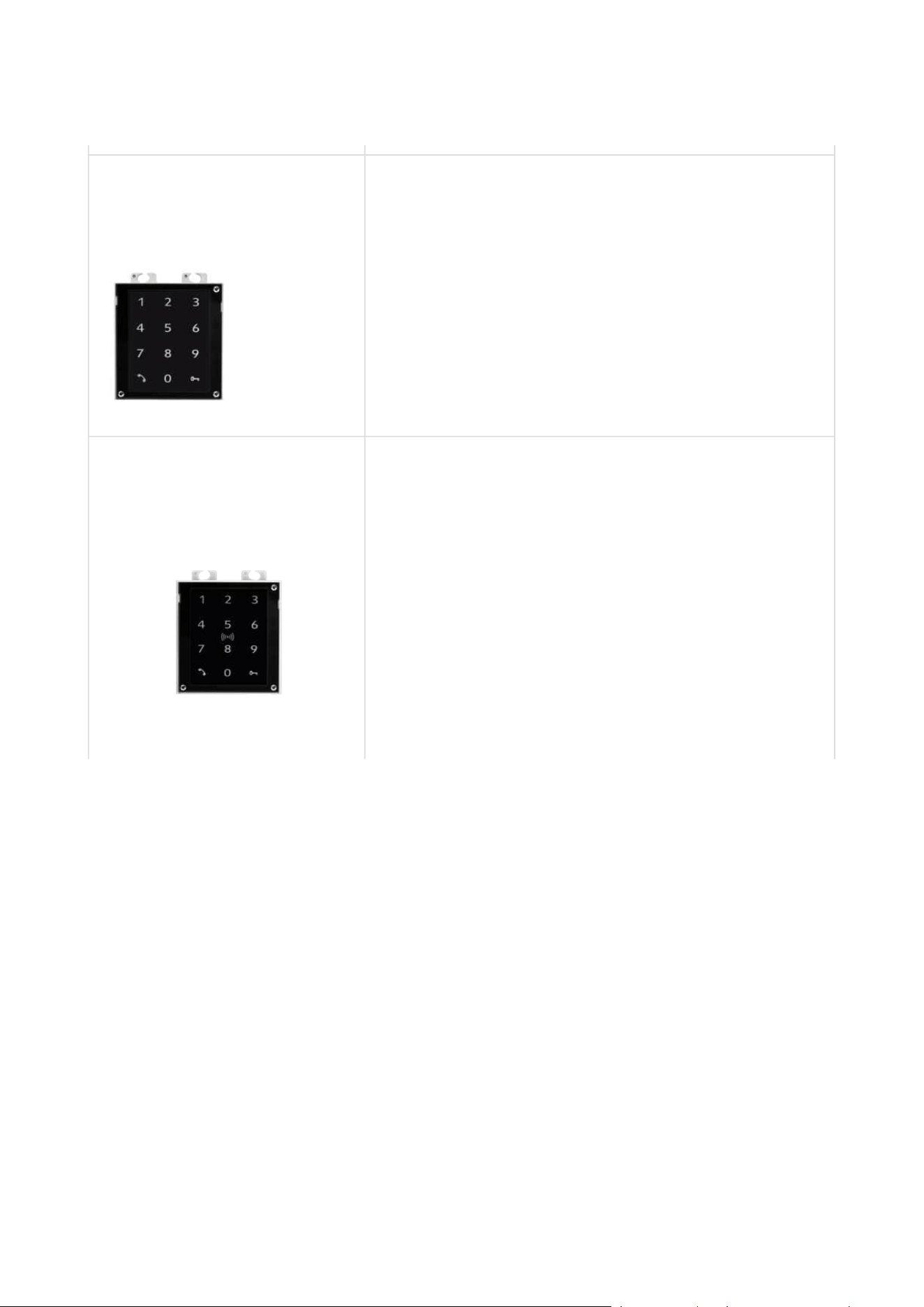
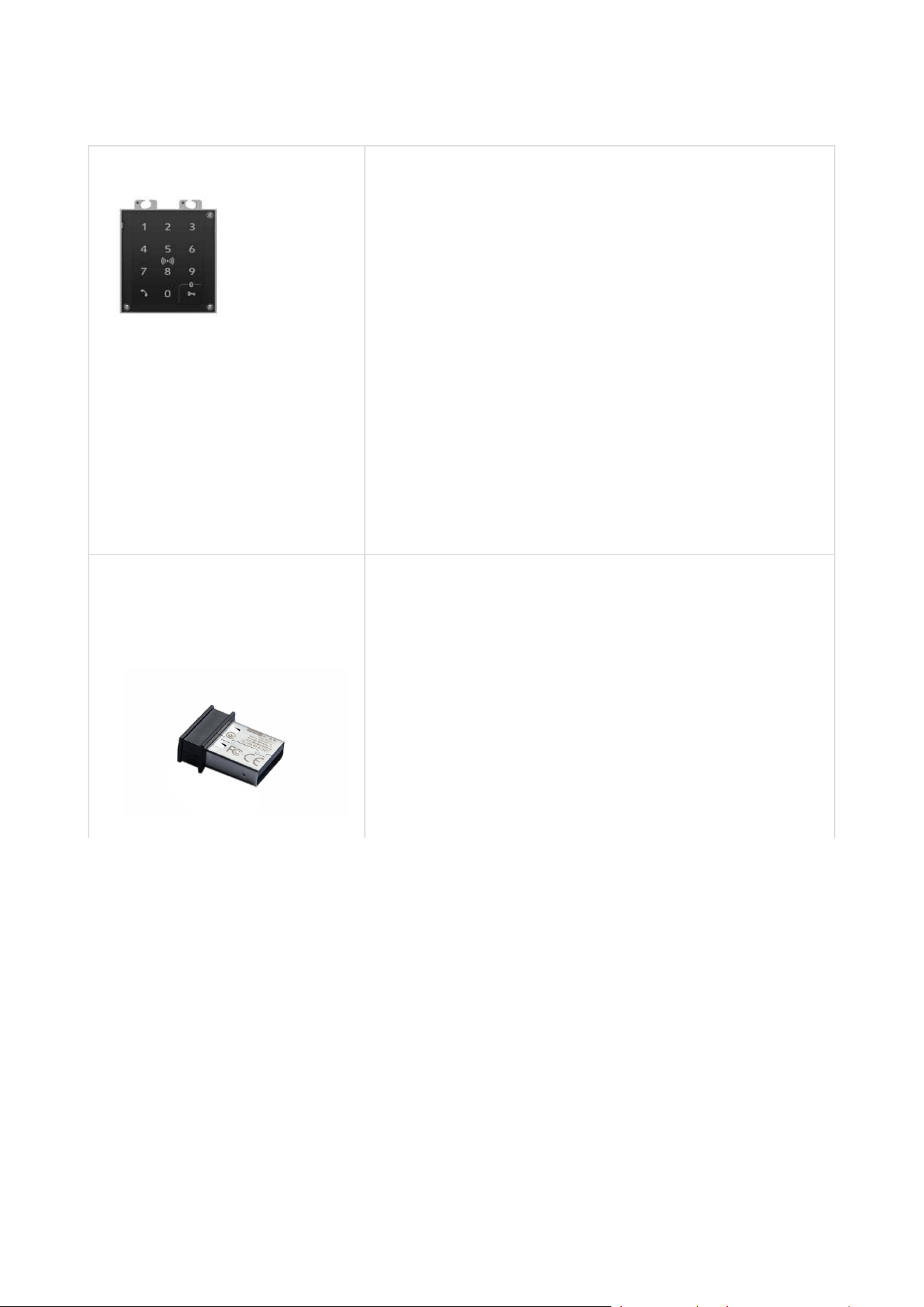
2N Part No.9155047
Axis Part No. 01277-001
2N IP Verso 2.0 – Touch keypad
The numeric touch keypad module helps you dial
users via their phonebook positions or phone
numbers, control the lock and use other code-
accessible functions. The keypad digits and symbols
are backlit.
2N Part No.9155081
Axis Part No. 01636-001
2N IP Verso 2.0 – Touch keypad & RFID reader 125kHz,
13.56MHz, NFC
The combined keypad & card reader module provides
access control using contactless cards or key fobs. The
module supports 125 kHz and 13.56 MHz cards or
other carriers of the same frequencies:
125 kHz
EM4xxx
13.56 MHz
ISO14443A (MIFARE, MIFARE DESFire)
PicoPass (HID iClass)
FeliCa
ST SR(IX)
2NMobile Key

Installation manual 2N® IP Verso 2.0
15 / 213
•
•
•
•
•
•
•
•
•
2N Part No. 91550946
2N IP Verso 2.0 – Touch keypad & RFID reader 125kHz,
13.56MHz, NFC
The combined keypad & card reader module provides
access control using contactless cards or key fobs. The
module supports 125 kHz and 13.56 MHz cards or
other carriers of the same frequencies:
125 kHz
EM4xxx
13.56 MHz
ISO14443A (MIFARE, MIFARE DESFire)
PicoPass (HID iClass)
FeliCa
ST SR(IX)
2NMobile Key
Installation manual 2N® IP Verso 2.0
16 / 213
•
•
•
•
•
•
•
•
•
•
•
•
•
•
•
•
•
•
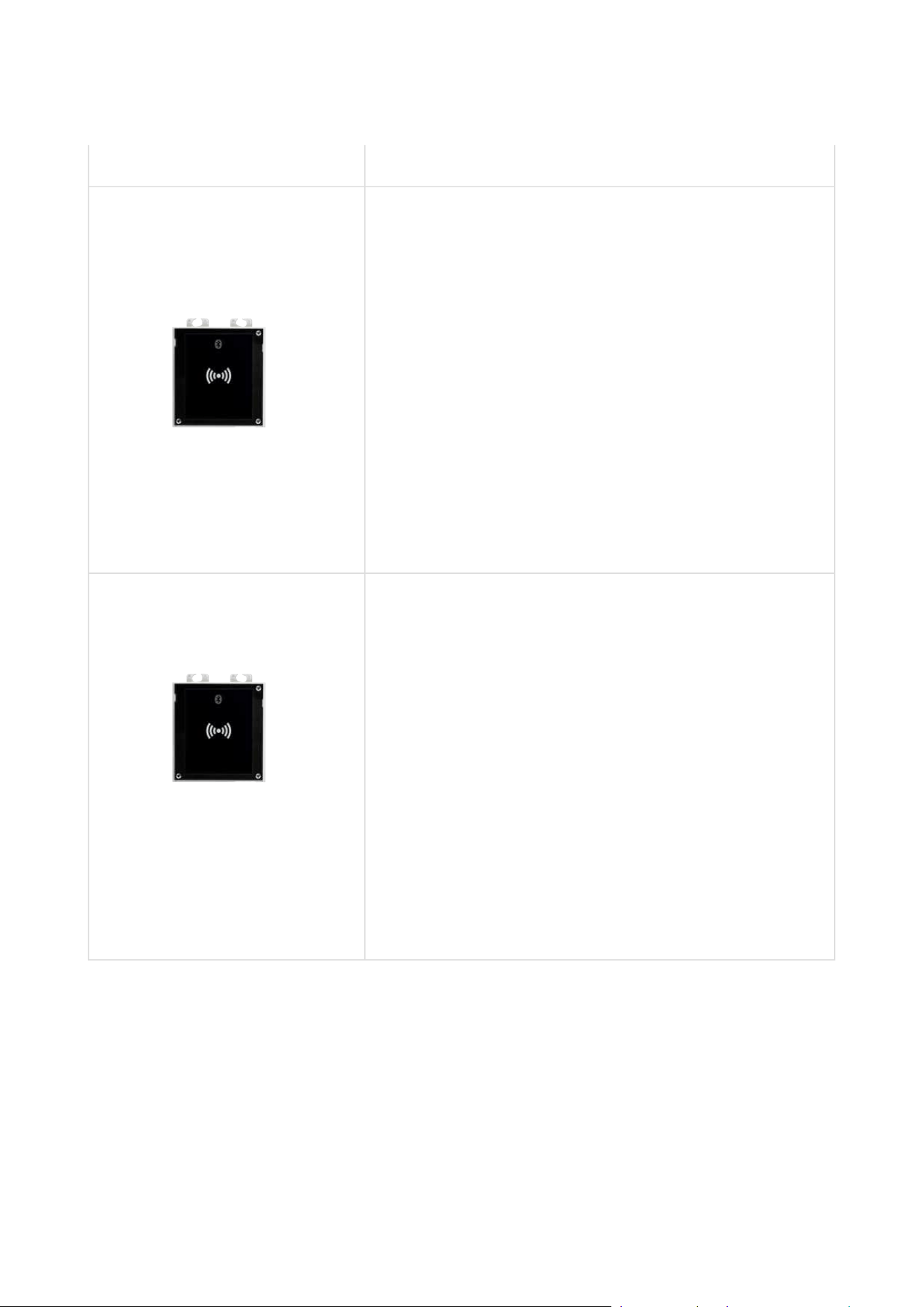
2N Part No.9155082
Axis Part No. 01637-001
2N IP Verso 2.0 – Bluetooth & RFID reader 125kHz,
13.56MHz, NFC
The combined Bluetooth & card reader module
provides access control using an access code, the
2NMobile Key application in your smartphone or an
access card. The module supports 125 kHz and 13.56
MHz cards or other carriers of the same frequencies:
125 kHz
EM4xxx
13.56 MHz
ISO14443A (MIFARE, MIFARE
DESFire)
PicoPass (HID iClass)
FeliCa
ST SR(IX)
2N Mobile Key
2N Part No. 91550945
2N IP Verso 2.0 – Bluetooth & RFID reader 125kHz,
13.56MHz, NFC
The combined Bluetooth & card reader module
provides access control using an access code, the
2NMobile Key application in your smartphone or an
access card. The module supports 125 kHz and 13.56
MHz cards or other carriers of the same frequencies:
125 kHz
EM4xxx
13.56 MHz
ISO14443A (MIFARE, MIFARE
DESFire)
PicoPass (HID iClass)
FeliCa
ST SR(IX)
2N Mobile Key

Installation manual 2N® IP Verso 2.0
17 / 213
•
•
•
•
•
•
•
•
•
•
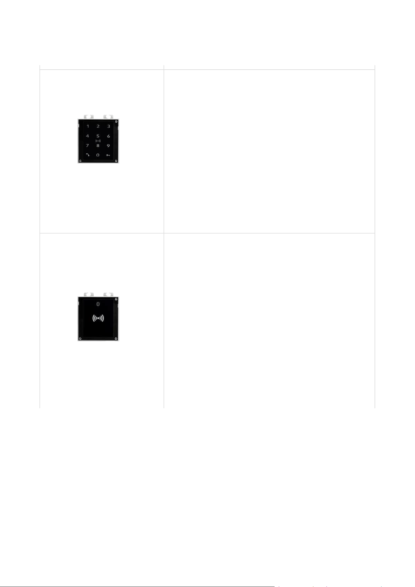
2N Part No.9155083
Axis Part No. 01638-001
2N IP Verso 2.0 – Touch keypad & RFID reader 125kHz,
secured 13.56MHz, NFC
The combined keypad & card reader module provides
access control using contactless cards or key fobs. The
module supports 125 kHz and 13.56 MHz cards or
other carriers of the same frequencies:
125 kHz
EM4xxx
13.56 MHz
ISO14443A (MIFARE, MIFARE DESFire)
PicoPass (HID iClass)
FeliCa
ST SR(IX)
2NMobile Key
HID SE (Seos, iClass SE, MIFARE SE)
Installation manual 2N® IP Verso 2.0
18 / 213
•
•
•
•
•
•
•
•
•
•
•
•
•
•
•
•
•
•
•
•
2N Part No. 91550946-S
2N IP Verso 2.0 – Touch keypad & RFID reader 125kHz,
secured 13.56MHz, NFC
The combined keypad & card reader module provides
access control using contactless cards or key fobs. The
module supports 125 kHz and 13.56 MHz cards or
other carriers of the same frequencies:
125 kHz
EM4xxx
13.56 MHz
ISO14443A (MIFARE, MIFARE DESFire)
PicoPass (HID iClass)
FeliCa
ST SR(IX)
2NMobile Key
HID SE (Seos, iClass SE, MIFARE SE)
2N Part No.9155084
Axis Part No. 01639-001
2N IP Verso 2.0 – Bluetooth & RFID reader 125kHz,
secured 13.56MHz, NFC
The combined Bluetooth & card reader module
provides access control using an access code, the
2NMobile Key application in your smartphone or an
access card. The module supports 125 kHz and 13.56
MHz cards or other carriers of the same frequencies:
125 kHz
EM4xxx
13.56 MHz
ISO14443A (MIFARE, MIFARE
DESFire)
PicoPass (HID iClass)
FeliCa
ST SR(IX)
2NMobile Key
HID SE (Seos, iClass SE, MIFARE SE)
Installation manual 2N® IP Verso 2.0
19 / 213
•
•
•
•
•
•
•
•
•
•
•
•
•
•
•
•
•
•
•
•
2N Part No. 91550945-S
2N IP Verso 2.0 – Bluetooth & RFID reader 125kHz,
secured 13.56MHz, NFC
The combined Bluetooth & card reader module
provides access control using an access code, the
2NMobile Key application in your smartphone or an
access card. The module supports 125 kHz and 13.56
MHz cards or other carriers of the same frequencies:
125 kHz
EM4xxx
13.56 MHz
ISO14443A (MIFARE, MIFARE
DESFire)
PicoPass (HID iClass)
FeliCa
ST SR(IX)
2NMobile Key
HID SE (Seos, iClass SE, MIFARE SE)
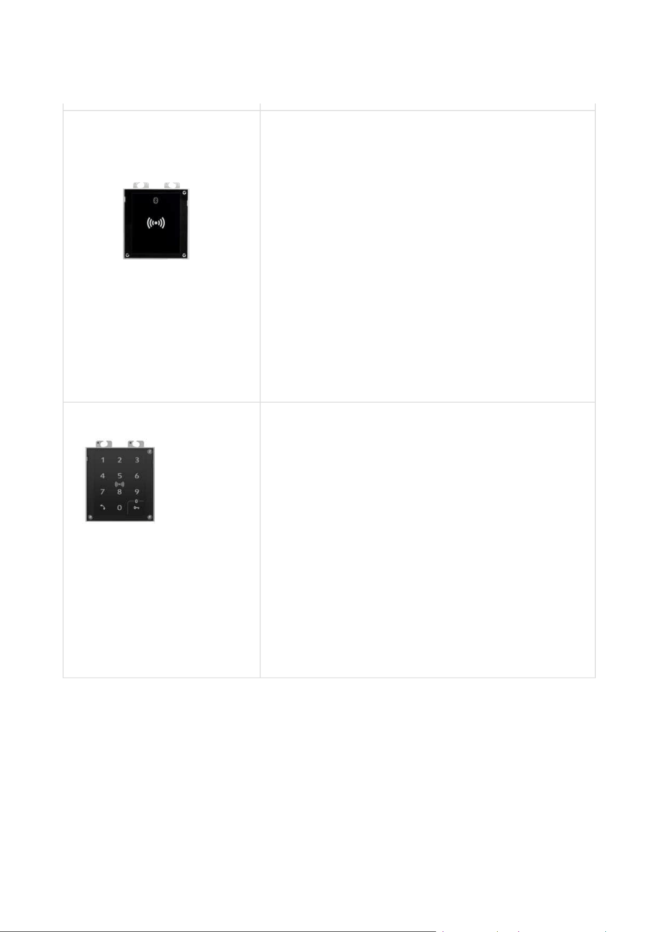
2N Part No. 91550947 2N IP Verso 2.0– Touch keypad & Bluetooth & RFID
reader 125kHz, 13.56MHz, NFC
The combined keypad & Bluetooth & card reader
module provides access control using an access code,
the 2N Mobile Key application in your smartphone or
an access card. The module supports 125 kHz and
13.56 MHz cards or other carriers of the same
frequencies:
125 kHz
EM4xxx
13.56 MHz
ISO14443A (MIFARE, MIFARE DESFire)
PicoPass (HID iClass)
FeliCa
ST SR(IX)
2N Mobile Key
Installation manual 2N® IP Verso 2.0
20 / 213
•
•
•
•
•
•
•
•
•
•
2N Part No. 91550947-S 2N IP Verso 2.0– Touch keypad & Bluetooth & RFID
reader 125kHz, secured 13.56MHz, NFC
The combined keypad & Bluetooth & card reader
module provides access control using an access code,
the 2N Mobile Key application in your smartphone or
an access card. The module supports 125 kHz and
13.56 MHz cards or other carriers of the same
frequencies:
125 kHz
EM4xxx
13.56 MHz
ISO14443A (MIFARE, MIFARE DESFire)
PicoPass (HID iClass)
FeliCa
ST SR(IX)
2NMobile Key
HID SE (Seos, iClass SE, MIFARE SE)
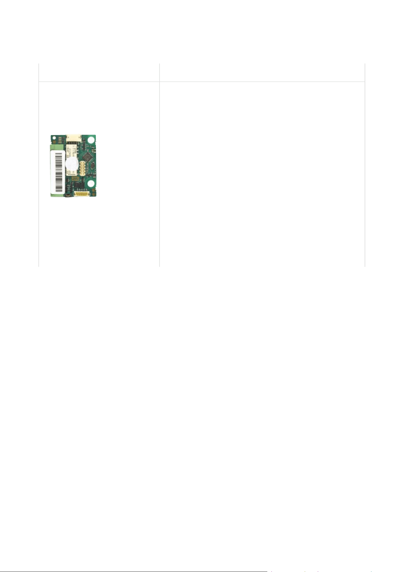
2N Part No. 9137422E
Axis Part No. 01402-001
2N IP external Bluetooth reader (USB interface)
An external Bluetooth reader connecting to your
computer via USB.
It can be used to pair new users who want to use their
smartphones and 2N Mobile Key application for access to
controlled areas.
A USB driver is required for the external reader to work
properly.
Installation manual 2N® IP Verso 2.0
21 / 213
•
•
•
•
•
•
•
•
2N Part No. 9155034
Axis Part No. 01257-001
2N IP Verso 2.0 – I/O
The module provides logical inputs and outputs for
sensor integration. The module is installed under
another module, i.e. needs no separate position.
Inputs and outputs
RELAY1 – RELAY1 terminals with accessible 30 V /
1 A AC/DC NO/NC contact
RELAY2 – RELAY2 terminals with accessible 30 V /
1 A AC/DC NO/NC contact
IN1 – IN1 terminals for input in passive/ active
mode(−30 V to +30 V DC)
OFF = open OR U
IN
> 1.5 V
ON = closed contact OR U
IN
< 1.5 V
IN2 – IN2 terminals for input in passive/active
mode(−30 V to +30 V DC)
OFF = open OR U
IN
> 1.5 V
ON = closed contact OR U
IN
< 1.5 V
TAMPER – Tamper switch (9155038) input
Installation manual 2N® IP Verso 2.0
22 / 213
•
•
•
•
•
•
2N Part No.9155035
Axis Part No. 01258-001
2N IP Verso 2.0 – 5 buttons
A module with 5 mechanical quick dial buttons. The
buttons are backlit and can include nametags.
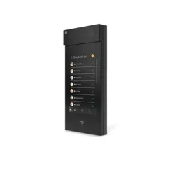
2N Part No.9155036
Axis Part No. 01275-001
2N IP Verso 2.0 – Touch Display
Touchscreen module allowing visitors to dial users in a
smartphone-like way. In addition to a structured
phonebook it also features a keypad.
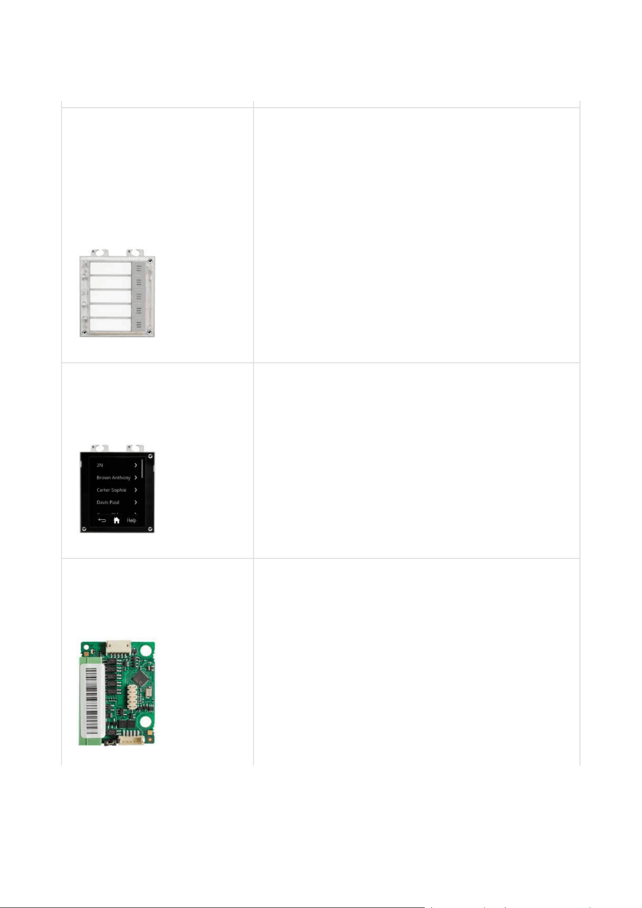
2N Part No.9155037
Axis Part No. 01259-001
2N IP Verso 2.0 – Wiegand
The module helps you interconnect your system with
other systems via the Wiegand interface. The module
is installed under another module, i.e. needs no
separate position.
Installation manual 2N® IP Verso 2.0
23 / 213
•
•
•
•
•
2N Part No. 91550371
Axis Part No. 02577-001
2NIPVerso 2.0– OSDP module
The OSDP moduleprovides communication between a
connected device (control panel, door controller)
and2N IP Verso 2.0via the OSDP. The module is
installed under another module, i.e. needs no separate
position.
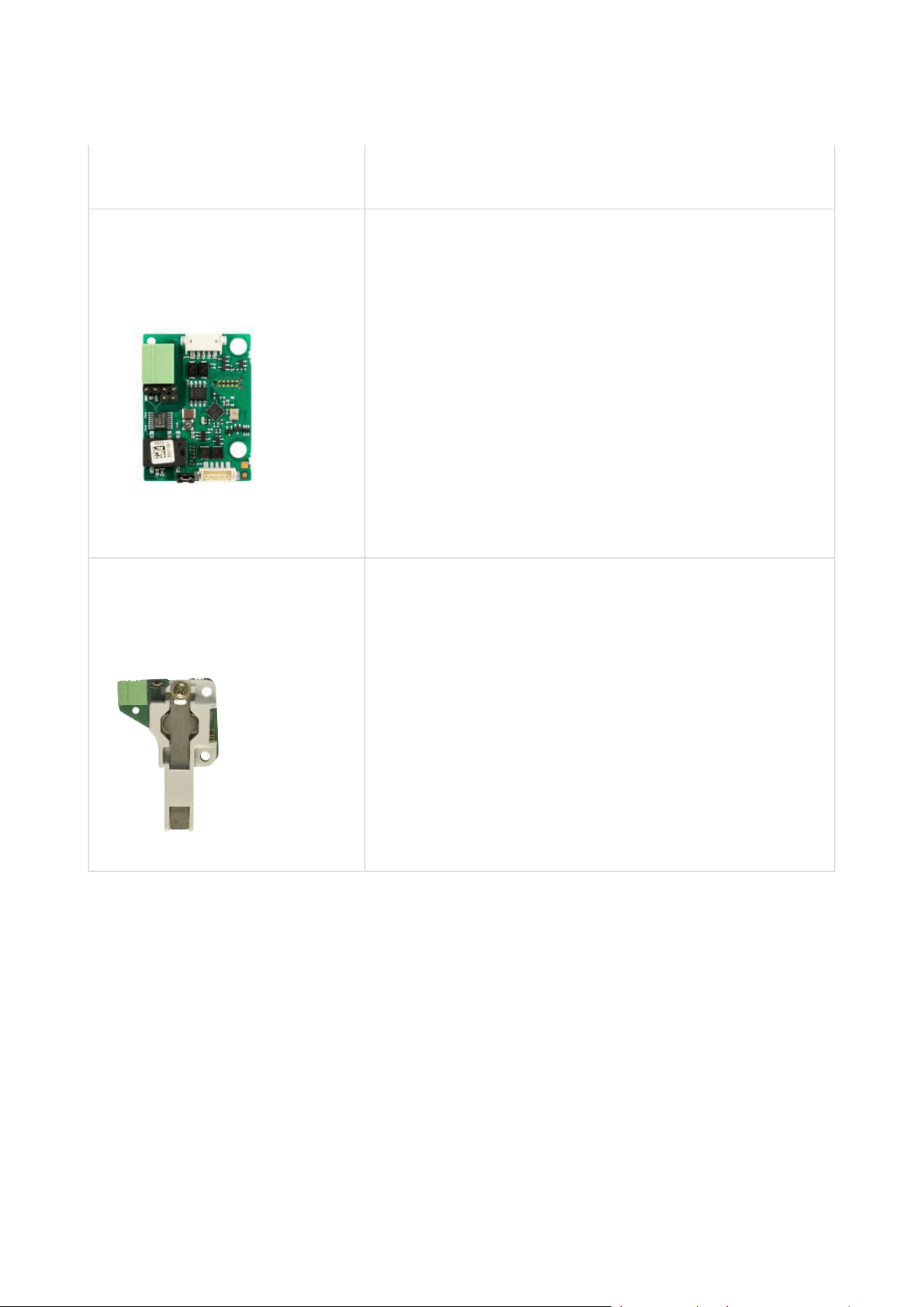
2N Part No.9155038
Axis Part No. 01260-001
2N IP Verso– Tamper switch
The module secures your system against tampering by
detecting intercom opening or top frame removing.
The module is installed on a special place and needs
no separate position.
Remember to purchase an I/O module, Part No.
9155034, together with the tamper switch.

Installation manual 2N® IP Verso 2.0
24 / 213
•
•
•
•
•
•
2N Part No.9155039
Axis Part No. 01261-001
2N IP Verso 2.0 –Blind Panel
One blind panel module is supplied with the main unit.
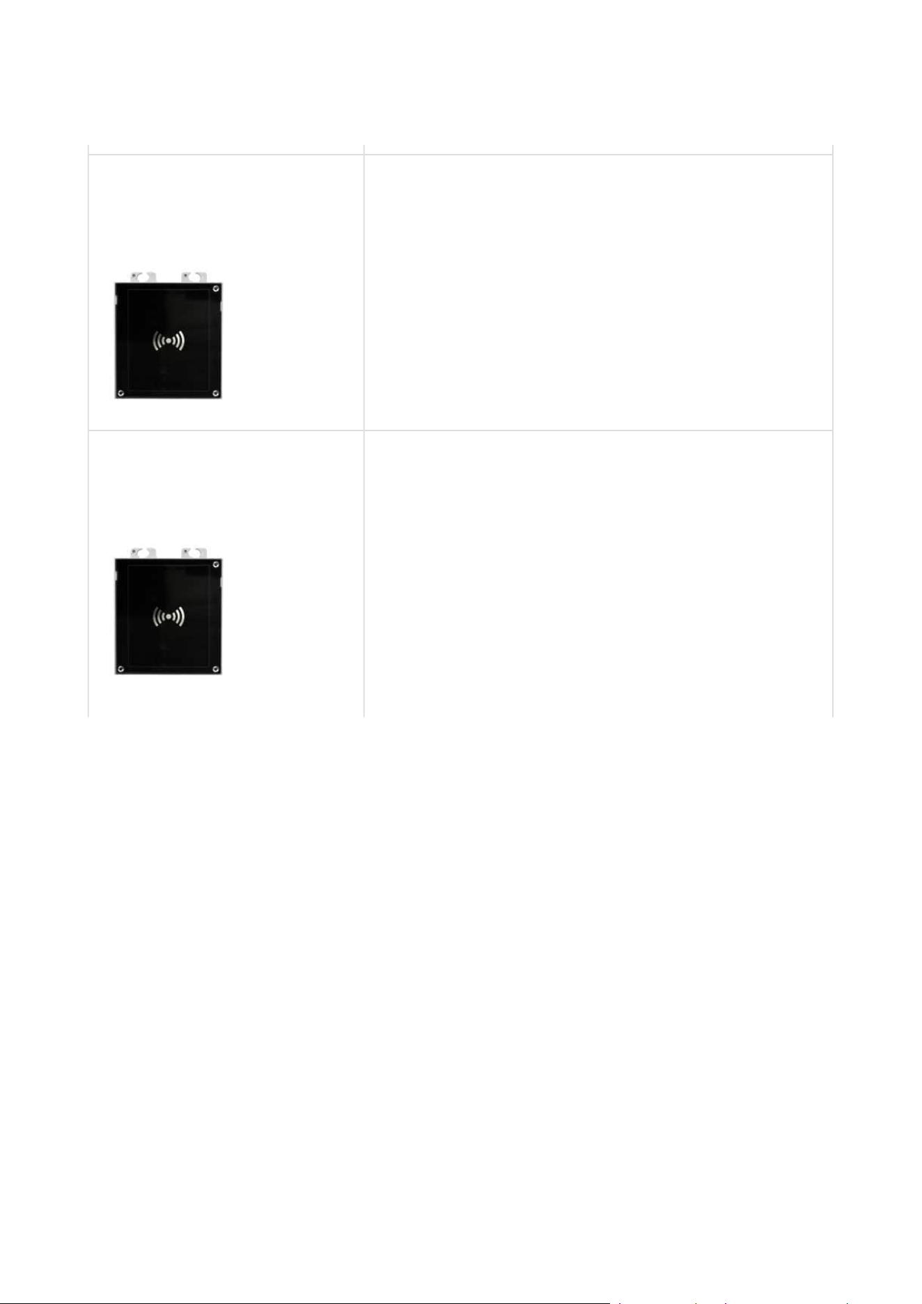
2N Part No. 91550941
2N IP Verso 2.0 – RFID Reader, 125 kHz
The card reader module provides you with access
control via contactless cards or keyfobs. The module
supports the 125 kHz EM4xxx cards.
2N Part No. 91550941US
Axis Part No. 02140-001
2N IP Verso 2.0 – RFID Reader, 125 kHz
The card reader module provides you with access
control via contactless cards or keyfobs. The module
supports the 125 kHz EM4xxx cards.
Installation manual 2N® IP Verso 2.0
25 / 213
•
•
•
•
•
•
•
•
•
•
•
•
•
•
•
2N Part No. 91550942
Axis Part No. 02139-001
2N IP Verso 2.0 – RFID Reader NFC support, 13.56 MHz
The card reader module provides you with access
control via contactless cards or keyfobs. The module
supports the following 13.56 MHz cards or other
carriers (only card serial number is read):
ISO14443A (MIFARE, MIFARE DESFire)
PicoPass (HID iClass)
FeliCa
ST SR(IX)
2NMobile Key
2N Part No. 91550942-S
Axis Part No. 02141-001
2N IP Verso 2.0 – Secured RFID Card Reader NFC
support, 13.56 MHz
The card reader module provides you with access
control via contactless cards or keyfobs. The module
supports the following 13.56 MHz cards or other
carriers (only card serial number is read):
ISO14443A (MIFARE, MIFARE DESFire)
PicoPass (HID iClass)
FeliCa
ST SR(IX)
2NMobile Key
HID SE (Seos, iClass SE, MIFARE SE)
Installation manual 2N® IP Verso 2.0
26 / 213
•
•
•
•
•
•
•
•
•
•
•
•
•
2N Part No.9155041
Axis Part No. 01263-001
2N IP Verso 2.0 – Induction loop
The induction loop module is used to transmit an
audio signal directly into a hearing aid via a magnetic
field.
2N Part No. 9155086
Axis Part No. 01264-001
2N IP Verso 2.0 – Secured RFID Card Reader NFC
support, 13.56 MHz
Compatible with firmware 2.13 and higher.
The card reader module provides you with access
control via contactless cards or keyfobs. The module
supports the following 13.56 MHz cards or other
carriers (optionally, the card serial number or PAC ID is
read):
ISO14443A (MIFARE, MIFARE DESFire)
PicoPass (HID iClass)
FeliCa
ST SR(IX)
2NMobile Key
HID SE (Seos, iClass SE, MIFARE SE)
2N Part No. 9155046
Axis Part No. 01266-001
2N IP Verso 2.0 – Bluetooth reader
The Bluetooth reader is used for reading users' secure
ID numbers from Android and iOS smartphone
applications.
Installation manual 2N® IP Verso 2.0
27 / 213
•
•
•
•
•
•
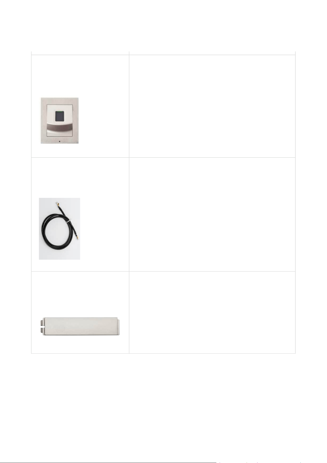
2N Part No. 9155045
Axis Part No. 01276-001
2N IP Verso 2.0 – Fingerprint reader
The Fingerprint reader is used for verification of
human fingers for access control and intercom
control.
2N Part No. 9155050
Axis Part No. 01267-001
1 m extension cable
Only one extension cable allowed.
Maximum bus length is 7 m.
2N Part. No. 9155051
Axis Part No. 01270-001
Blind button
Installation manual 2N® IP Verso 2.0
28 / 213
•
•
•
•
•
•
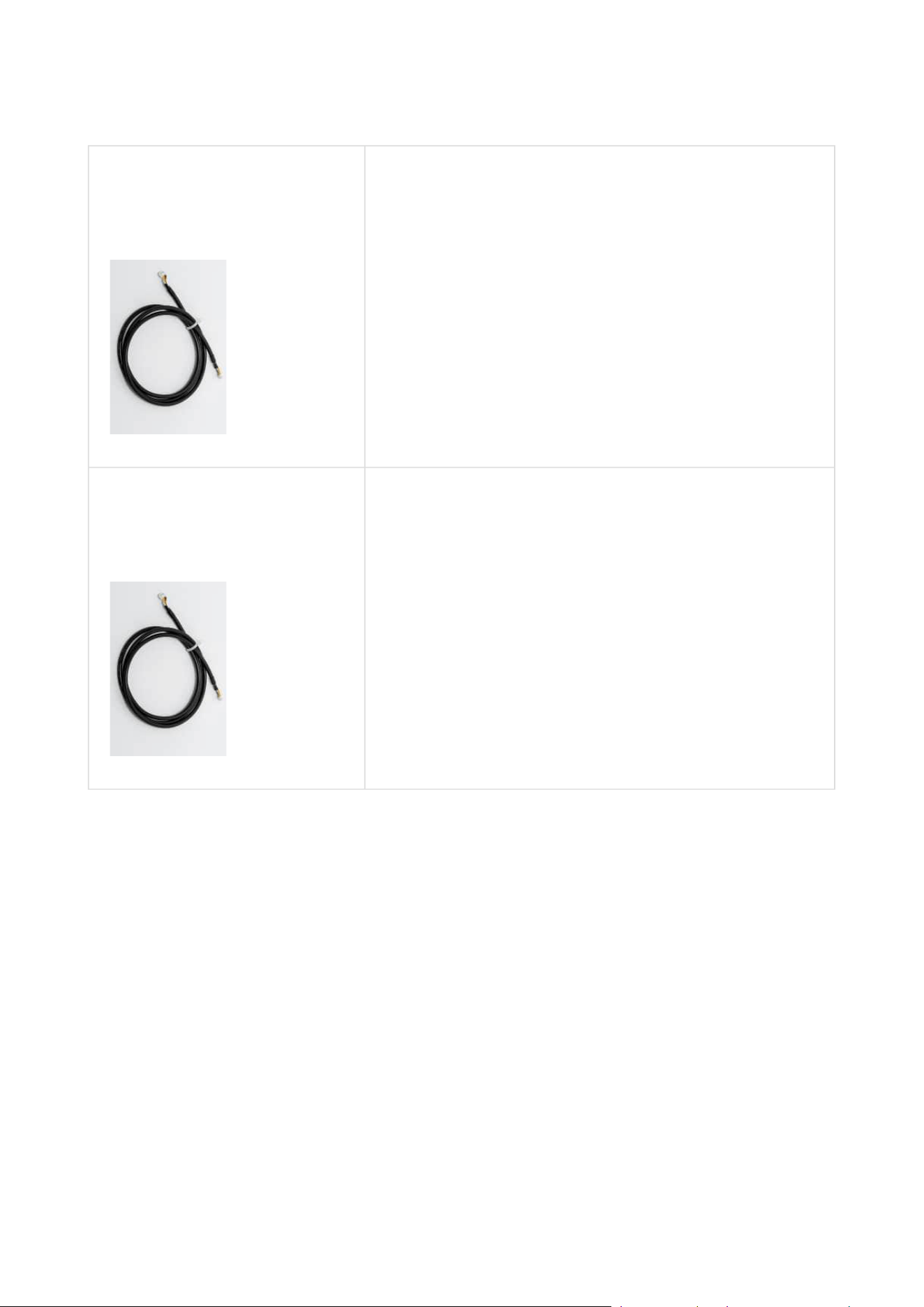
2N Part No. 9155054
Axis Part No. 01268-001
3 m extension cable
Only one extension cable allowed.
Maximum bus length is 7 m.
2N Part No. 9155055
Axis Part No. 01269-001
5 m extension cable
Only one extension cable allowed.
Maximum bus length is 7 m.
Installation manual 2N® IP Verso 2.0
29 / 213
•
•
•
•
•
•
Mounting Accessories
2N Part No.9155014
Axis Part No. 01284-001
Flush mounting box
1 module
Designed for flush or plasterboard mounting of 1-
module sets and delivered including accessories for
multiple box assemblies.
2N Part No.9155015
Axis Part No. 01285-001
Flush mounting box
2 modules
Designed for flush or plasterboard mounting of 2-
module sets and delivered including accessories for
multiple box assemblies.
Installation manual 2N® IP Verso 2.0
30 / 213
•
•
•
2N Part No.9155016
Axis Part No. 01286-001
Flush mounting box
3 modules
Designed for flush or plasterboard mounting of 3-
module sets and delivered including accessories for
multiple box assemblies

Installation manual 2N® IP Verso 2.0
31 / 213
•
•
•
•
•
•
2N Part No. 9155061
Axis Part No. 01293-001
Backplate, 1 module
For glass or uneven surface installation
2N Part No. 9155062
Axis Part No. 01294-001
Backplate, 2 modules
For glass or uneven surface installation
2N Part No. 9155063
Axis Part No. 01295-001
Backplate, 3 modules
For glass or uneven surface installation

Installation manual 2N® IP Verso 2.0
32 / 213
•
•
•
•
2N Part No. 9155064
Axis Part No. 01296-001
Backplate,2 (w) x 2 (h) modules
For glass or uneven surface installation
2N Part No. 9155065
Axis Part No. 01297-001
Backplate, 3 (w) x 2 (h) modules
For glass or uneven surface installation

Installation manual 2N® IP Verso 2.0
33 / 213
•
•
2N Part No. 9155066
Axis Part No. 01298-001
Backplate,2 (w) x 3 (h) modules
For glass or uneven surface installation
Installation manual 2N® IP Verso 2.0
34 / 213
•
•
•
•
2N Part No. 9155067
Axis Part No. 01299-001
Backplate, 3 (w) x 3 (h) modules
For glass or uneven surface installation
Part No. 9155072
Axis Part No. 01940-001
Wedge backplate
25°gradient mounting backplate
Choose the proper frame and, if necessary, mounting box type depending on your particular2N
IP Verso 2.0 installation needs.2N IP Verso 2.0is designed for outdoor applications and
requires no additional roof.
Installation manual 2N® IP Verso 2.0
35 / 213
•
•
•
•
2N Indoor Units and Accessories
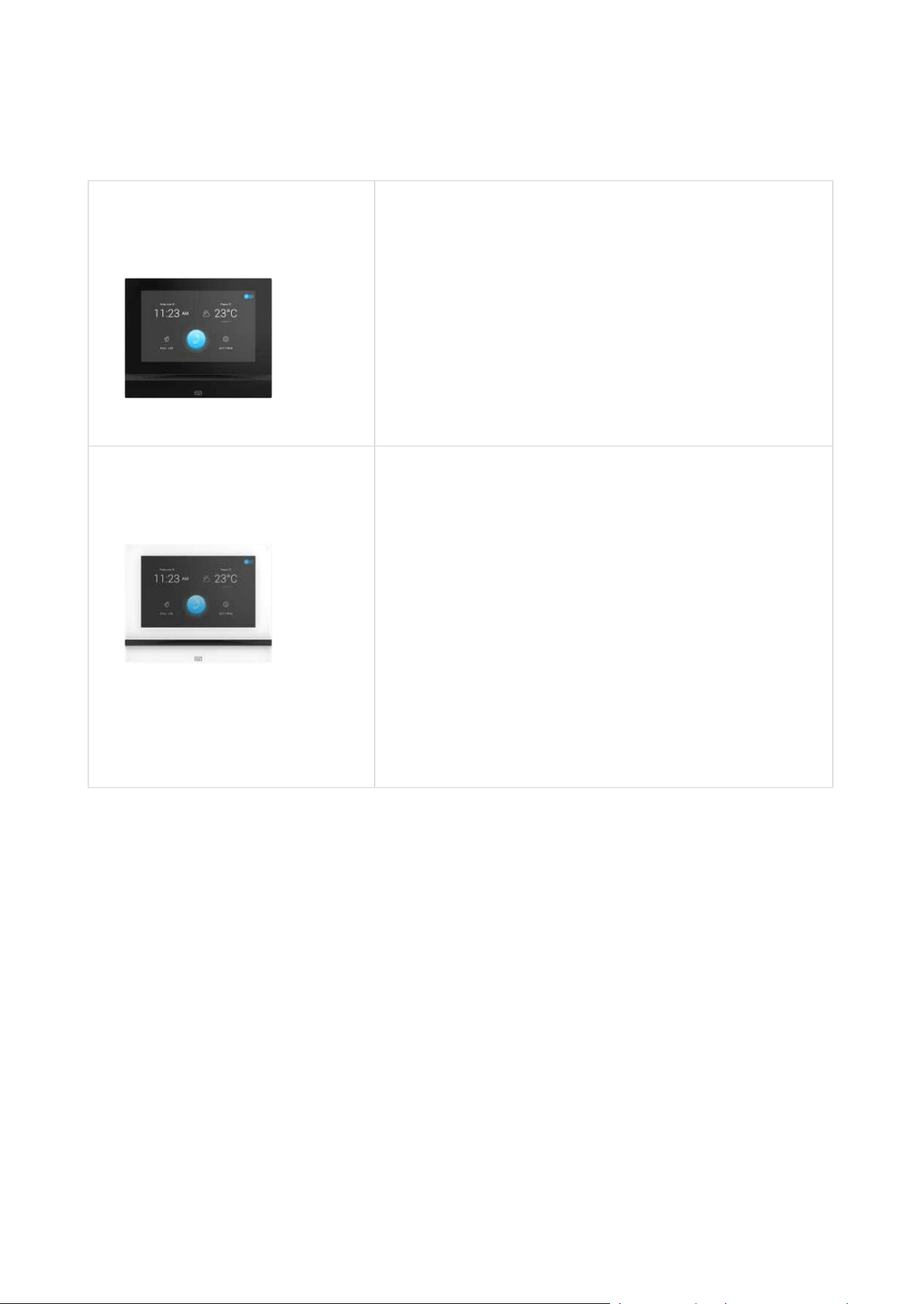
Part No. 91378601
2N Indoor View – black
Indoor answering audio/video unit with a
touchscreen designed for all 2N IP intercoms
Part No. 91378601WH
2N Indoor View – white
Indoor answering audio/video unit with a
touchscreen designed for all 2N IP intercoms
Installation manual 2N® IP Verso 2.0
36 / 213
•
•
•
•
Part No. 91378501
2N Indoor Compact – black
Indoor answering audio/video unit with a
touchscreen designed for all 2N IP intercoms
Part No. 91378501WH
2N Indoor Compact – white
Indoor answering audio/video unit with a
touchscreen designed for all 2N IP intercoms
Installation manual 2N® IP Verso 2.0
37 / 213
•
•
•
•
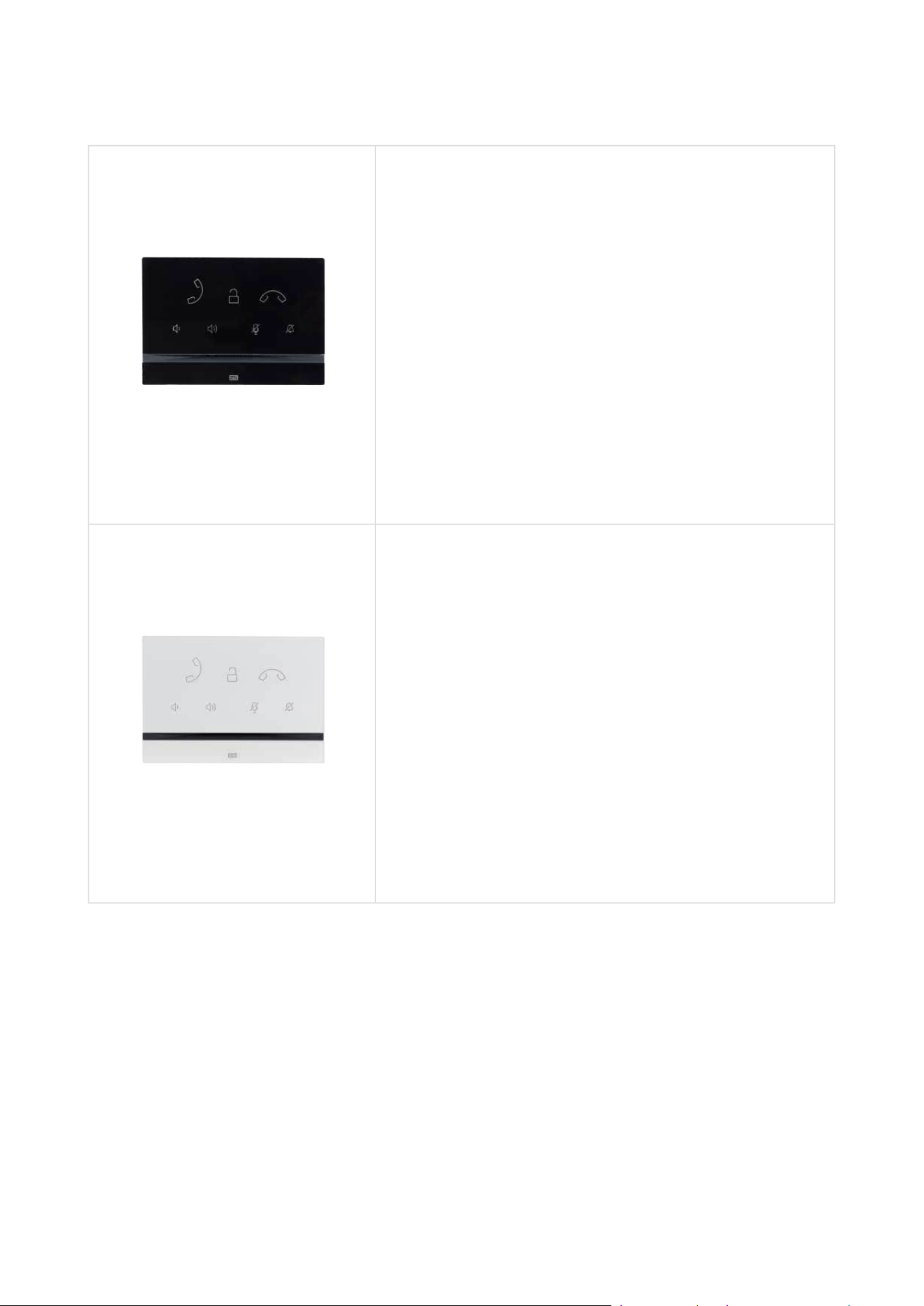
Part No. 91378401
2N Indoor Talk – black
Indoor answering audio unit with a touchscreen
designed for all 2N IP intercoms
Part No. 91378401WH
2N Indoor Talk – white
Indoor answering audio unit with a touchscreen
designed for all 2N IP intercoms
Installation manual 2N® IP Verso 2.0
38 / 213
•
•
Part No. 91378800
Wall/plasterboard flush mounting box for 2N indoor
answering units.
Part No. 91378803
Wall surface mounting box for 2N answering units.
Installation manual 2N® IP Verso 2.0
39 / 213
•
•
•
•
•
Part No. 91378802
Stand for 2N indoor answering units.
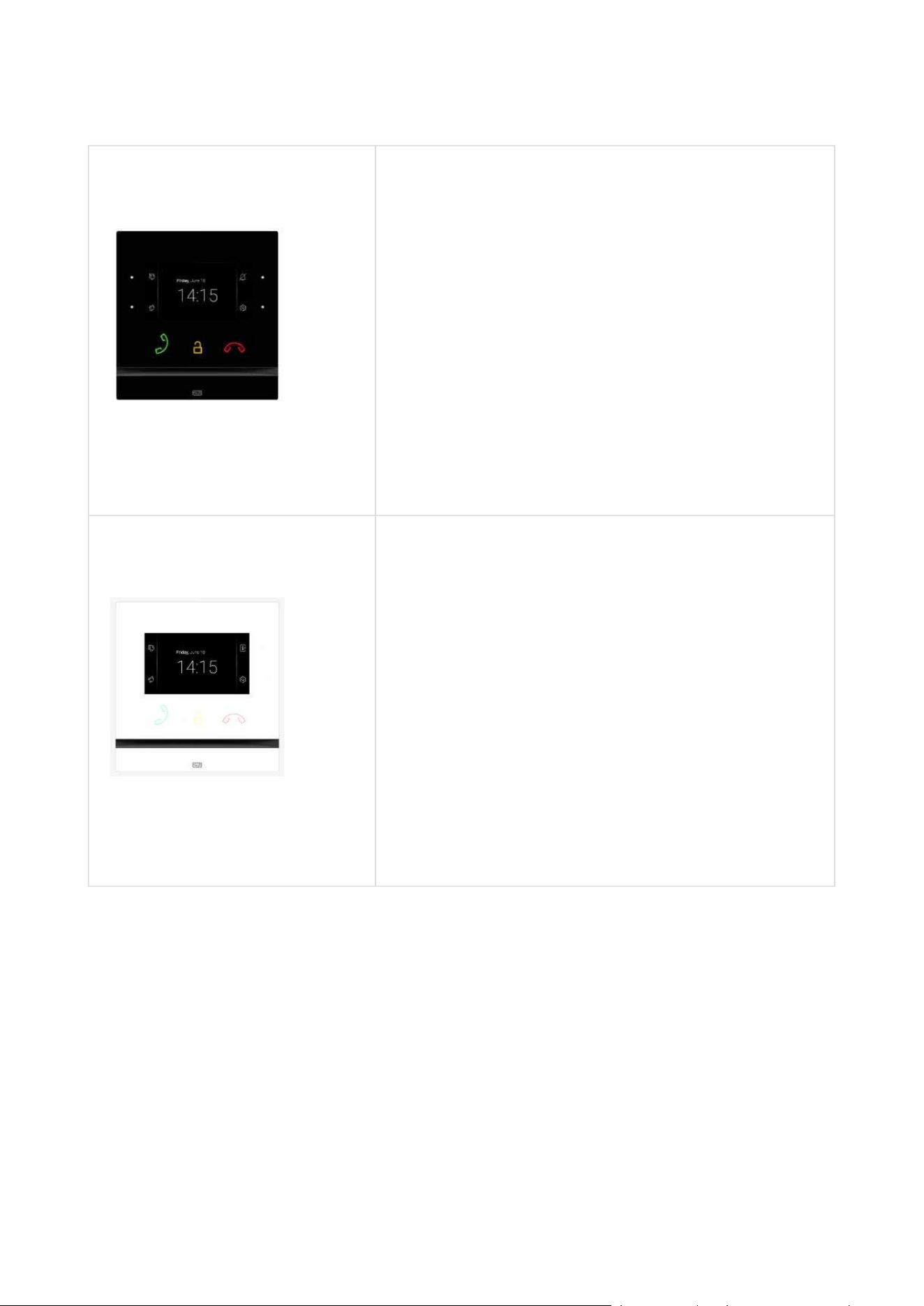
Part Numbers:
91378375
91378376
2N
Indoor Touch 2.0– black
WiFi version (second Part No.)
2N Indoor Touch 2.0, an elegant indoor touch panel,
is designed for all 2N IP intercoms. The display panel
shows you the person standing at your door and
helps you make conversation with the visitor, open
the door lock or switch on the entrance hall lights.
Part Number:
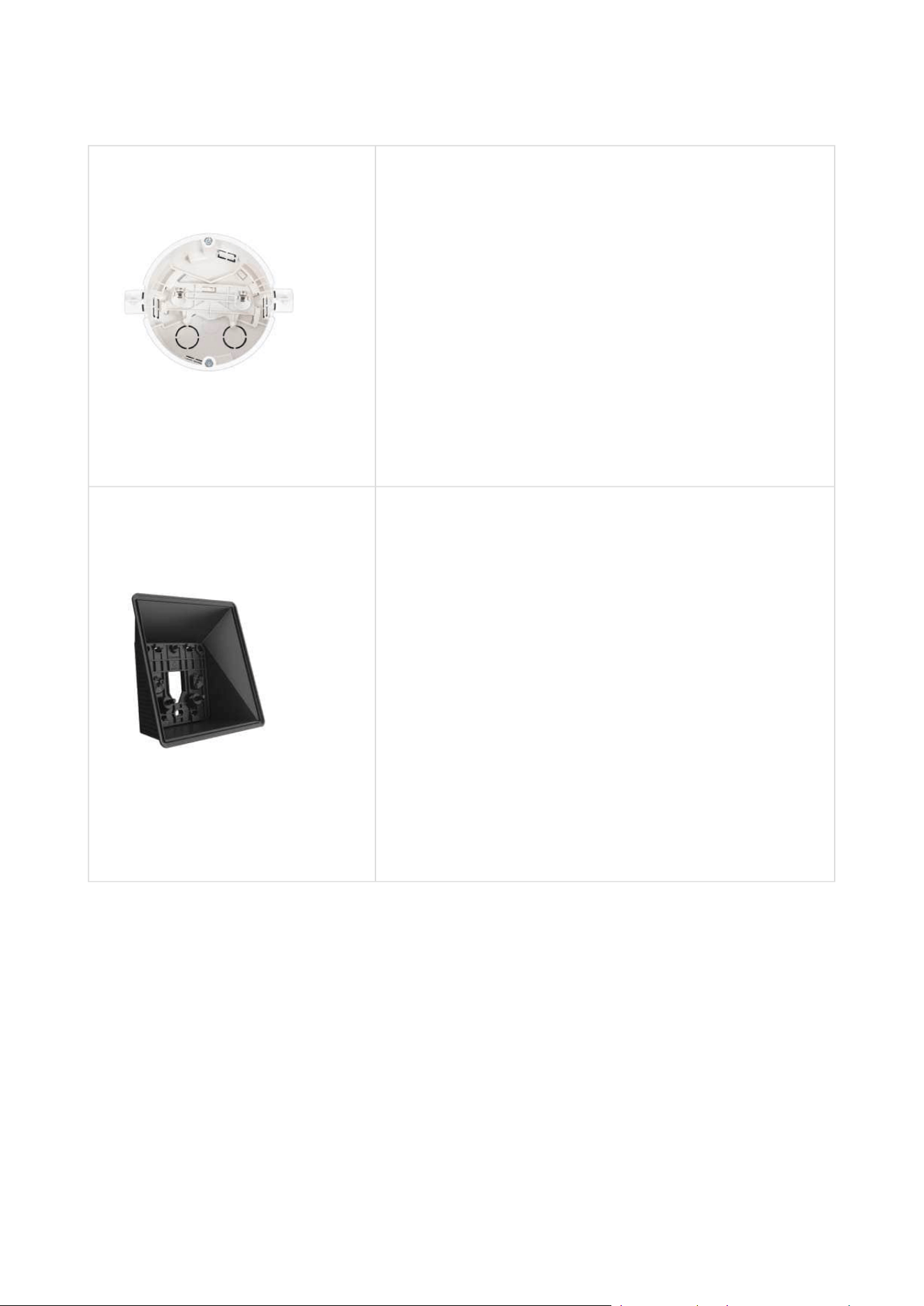
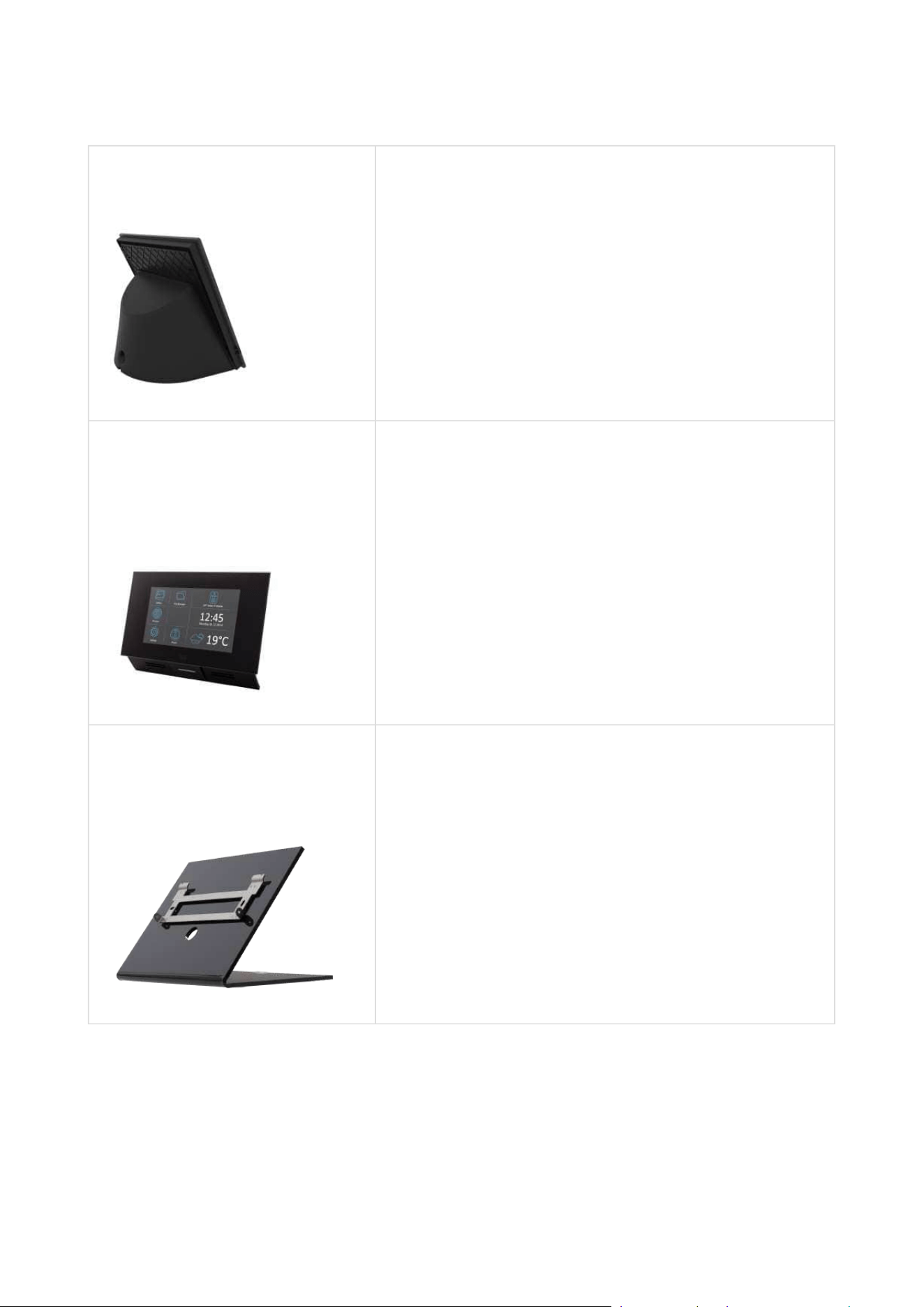
91378382
2N Indoor Touch – desk stand black

Installation manual 2N® IP Verso 2.0
40 / 213
•
•
•
Part Numbers:
91378375WH
91378376WH
2N
Indoor Touch 2.0– white
WiFi version (second Part No.)
2N Indoor Touch 2.0, an elegant indoor touch panel,
is designed for all of the 2N IP intercoms. The
display panel shows you the person standing at your
door and helps you make conversation with the
visitor, open the door lock or switch on the entrance
hall lights.
Installation manual 2N® IP Verso 2.0
41 / 213
•
•
•
•
•
•
•
Part Number:
91378382W
2N Indoor Touch– Desk stand white
Part Nos.:
91341481E
91341481GB
91341481US
The exclusive type of power adapter SYS1561-0912
to be used with all 2N Indoor Touch 2.0 devices.
Stabilised 12 V / 0,75 A source to be used where PoE
supply is unavailable.
The part numbers differ in their electric socket
markings (E/GB/US).
2N Part No. 1120101W
Axis Part No. 02518-001
2NIP Handset
answering unit
white color
Installation manual 2N® IP Verso 2.0
42 / 213
•
•
•
•
•
•
•
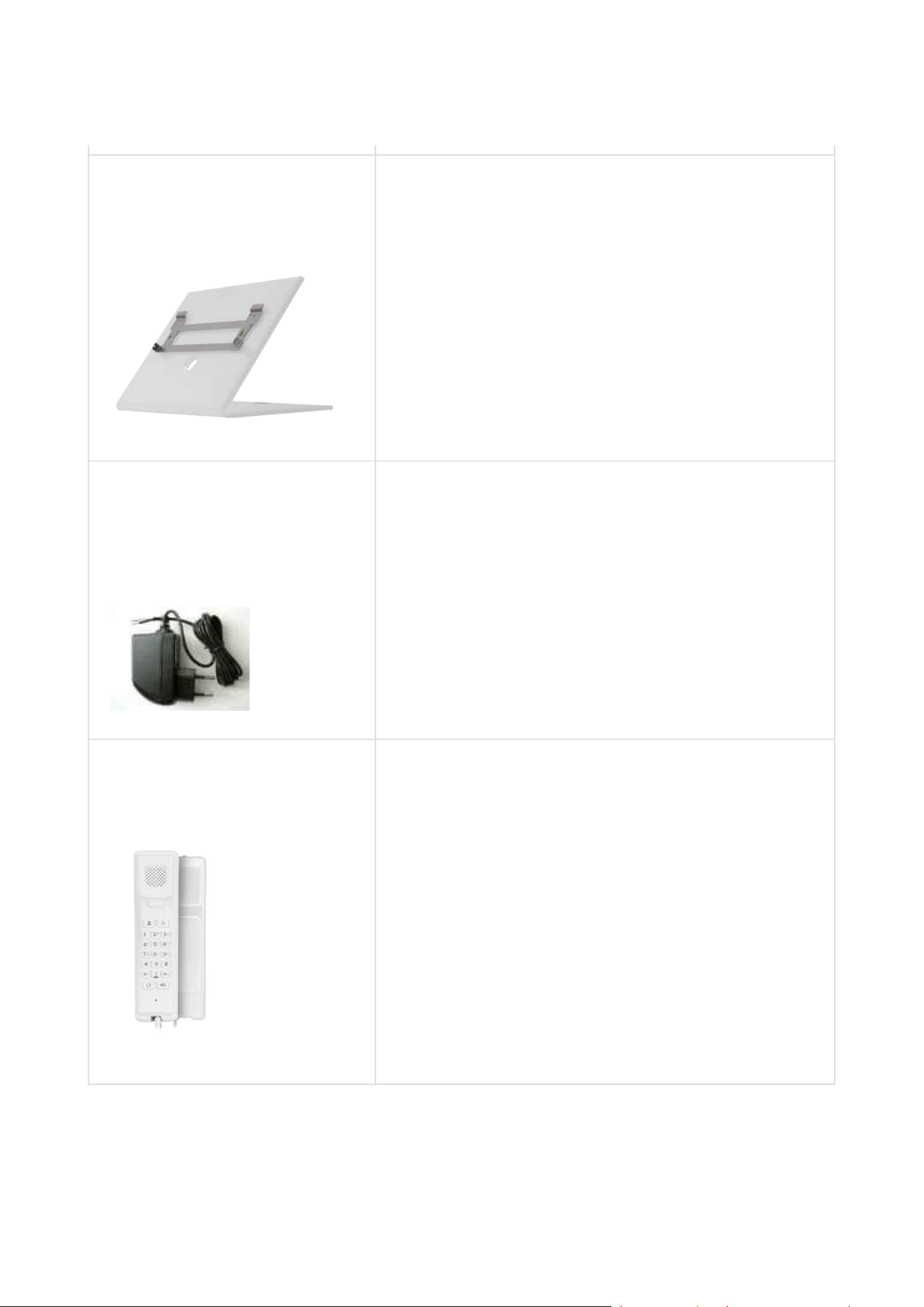
2N Part No. 1120101B
Axis Part No. 02519-001
2NIP Handset
answering unit
black color
IP Phones
2N Part No. 1120102
Axis Part No. 02660-001
2N IP Phone D7A
simple operation
HD quality video calls
A display-equipped extender EXP50 (Part
No.91378363) can be added to the phone
delivery to make up to 60 speed dialings.
Installation manual 2N® IP Verso 2.0
43 / 213
•
•
•
•
•
•
•
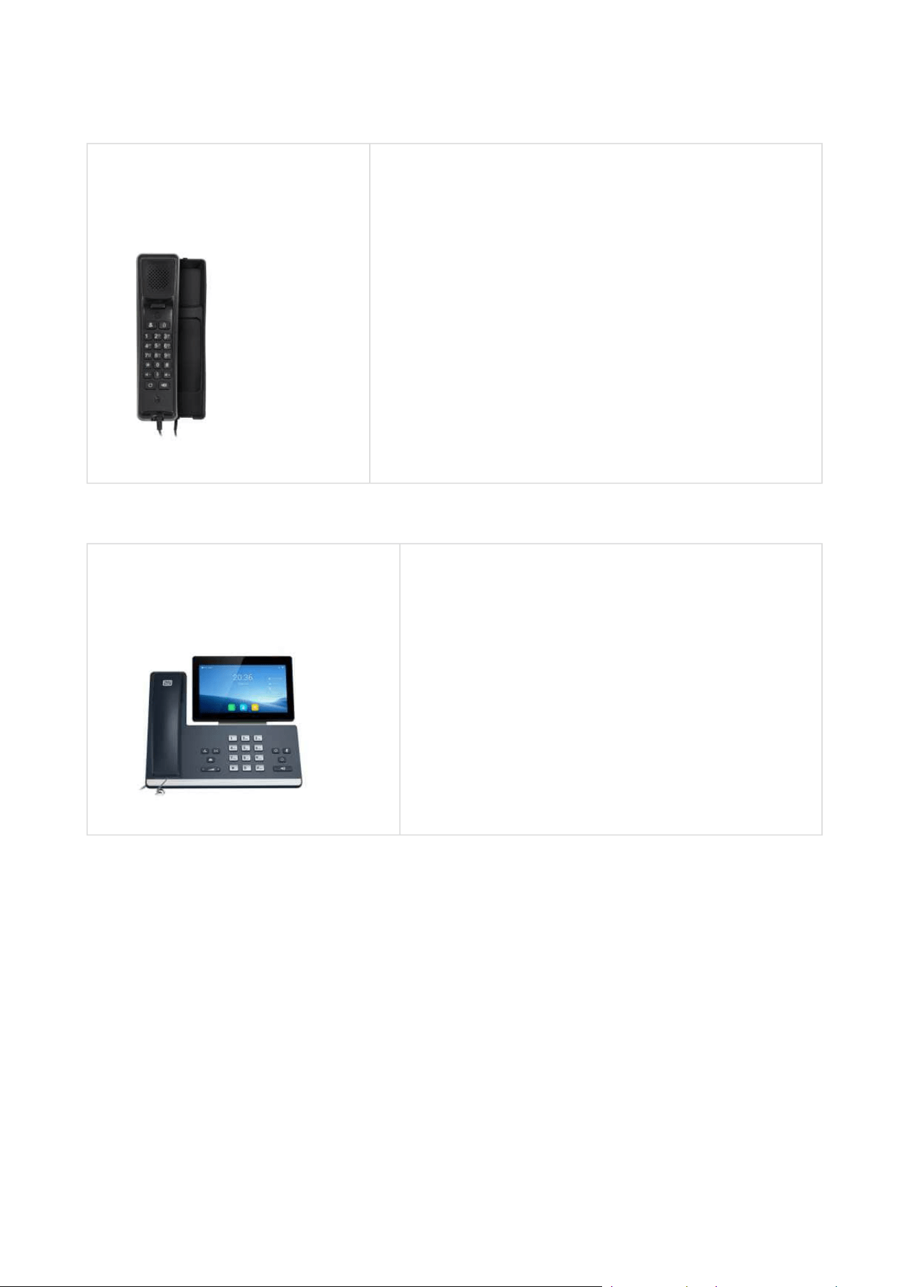
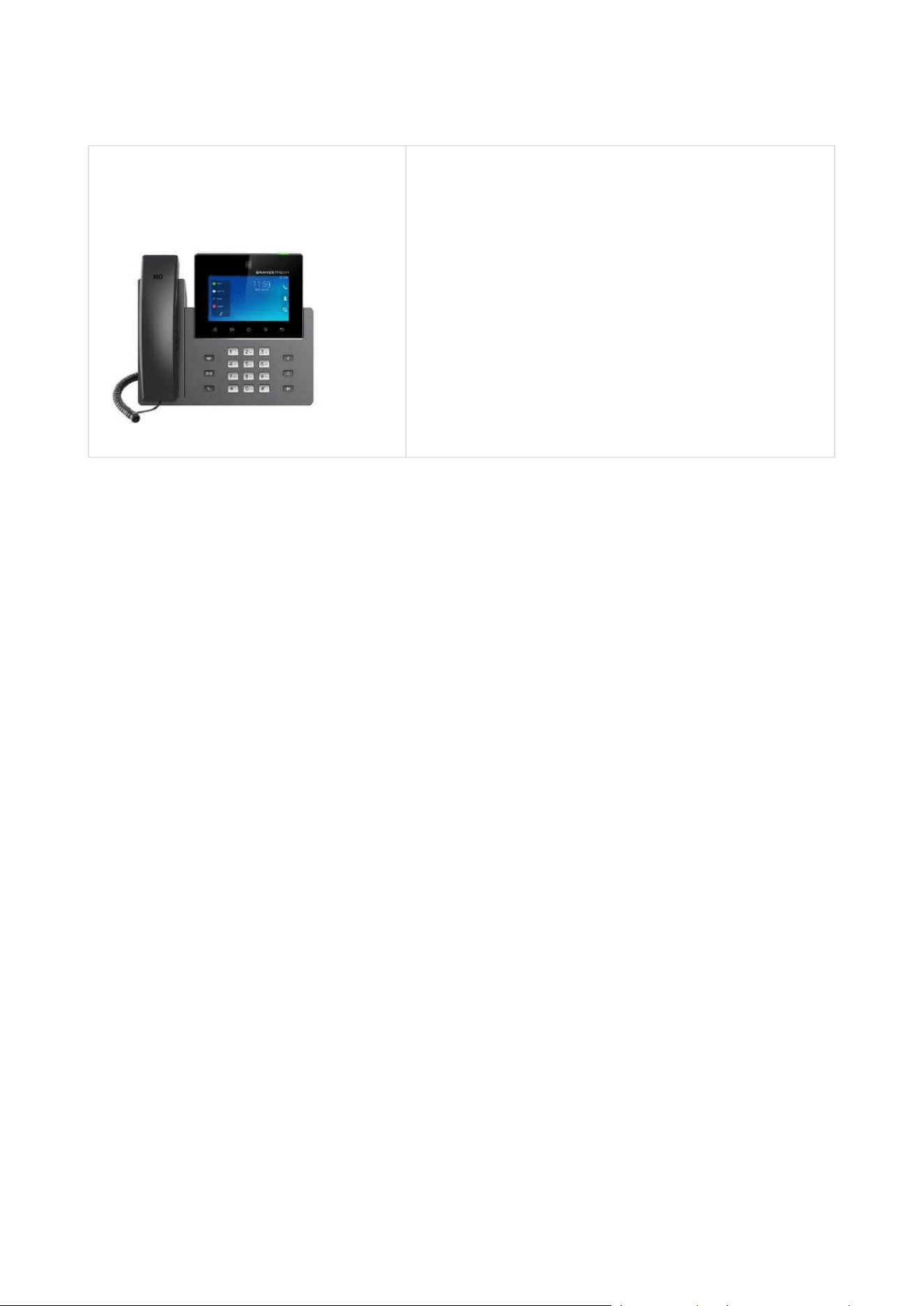
2N Part No. 1120111EU
Axis Part No.02544-001
Grandstream GXV3350 IP video phone
Android 7.0 OS
5” touch display control
HD quality video calls
WiFi and Bluetooth support
HDMI output and pan tilt zoom camera
Easy integration with intercoms or PBXs via SIP
Installation manual 2N® IP Verso 2.0
44 / 213
•
•
•
•
•
•
•
•
•
•
•
•
•
•
•
Electric Locks
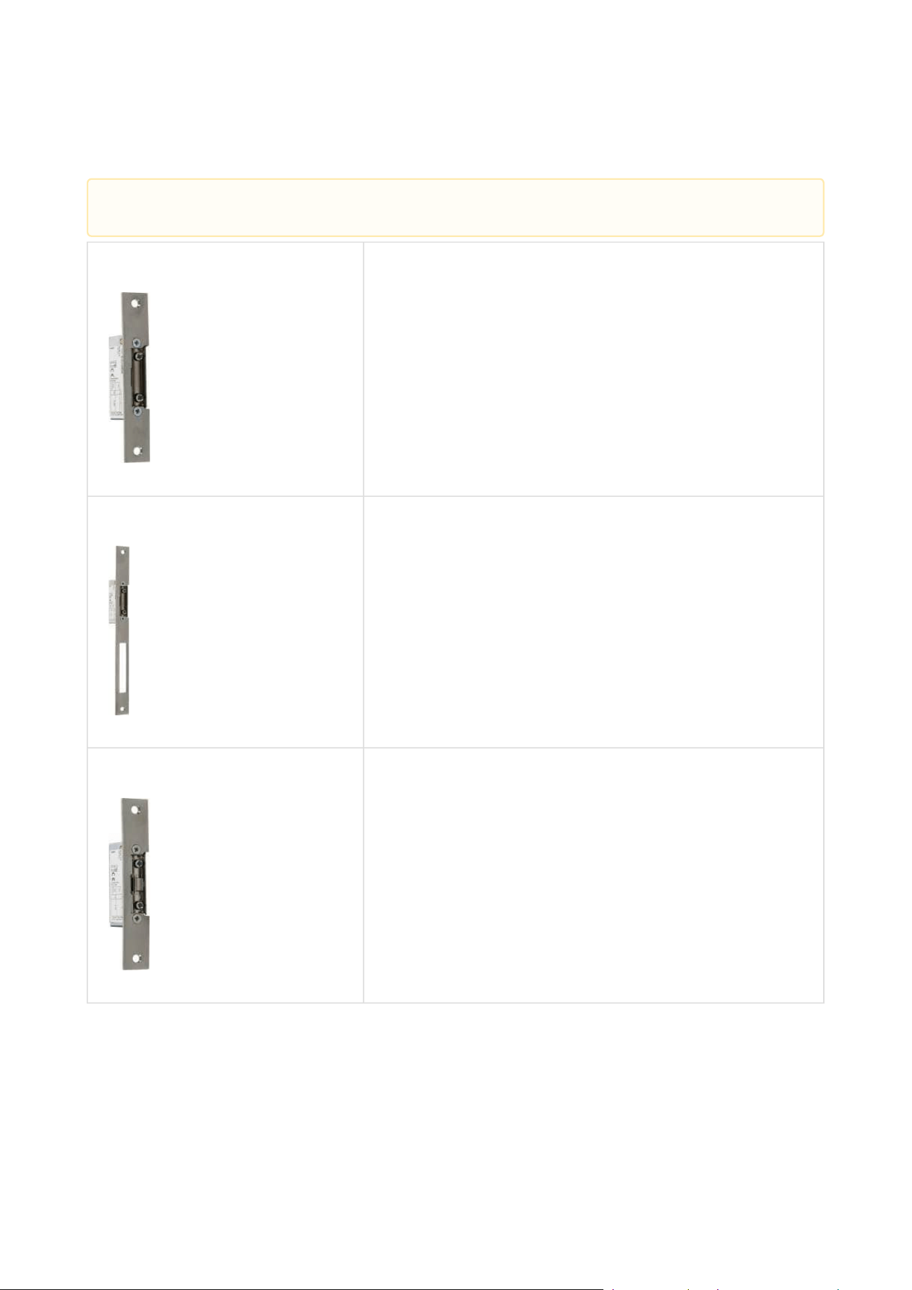
Part No. 11202101 Mini electronic doorstrike series 5
electric opener designed for door frame installation
intended for such narrow profiles as aluminum, wood
or PVC in particular
short sheet metal front cover version (130 mm)
16 mm width
Part No. 11202101-L Mini electronic doorstrike series 5, long
electric opener designed for door frame installation
intended for such narrow profiles as aluminum, wood
or PVC in particular
long sheet metal front cover version (250 mm)
16 mm width
Part No. 11202102 Mini electronic doorstrike series 5 - with
momentum pin
electric opener designed for door frame installation
intended for such narrow profiles as aluminum, wood
or PVC in particular
short sheet metal front cover version (130 mm)
16 mm width
• These products have been removed from sale.
Installation manual 2N® IP Verso 2.0
45 / 213
•
•
•
•
•
•
•
•
•
•
•
•
•
•
•
Part No. 11202102-L Mini electronic doorstrike series 5 - with
momentum pin, long
electric opener designed for door frame installation
intended for such narrow profiles as aluminum, wood
or PVC in particular
long sheet metal front cover version (250 mm)
16 mm width
Part No. 11202103
Mini electronic doorstrike series 5 - with
mechanical blocking
electric opener designed for door frame installation
intended for such narrow profiles as aluminum, wood
or PVC in particular
short sheet metal front cover version (130 mm)
16 mm width
Part No. 11202103-L Mini electronic doorstrike series 5 - with
mechanical blocking, long
electric opener designed for door frame installation
intended for such narrow profiles as aluminum, wood
or PVC in particular
long sheet metal front cover version (250 mm)
16 mm width
Installation manual 2N® IP Verso 2.0
46 / 213
•
•
•
•
•
•
•
•
•
•
•
•
•
•
•
•
•
•
•
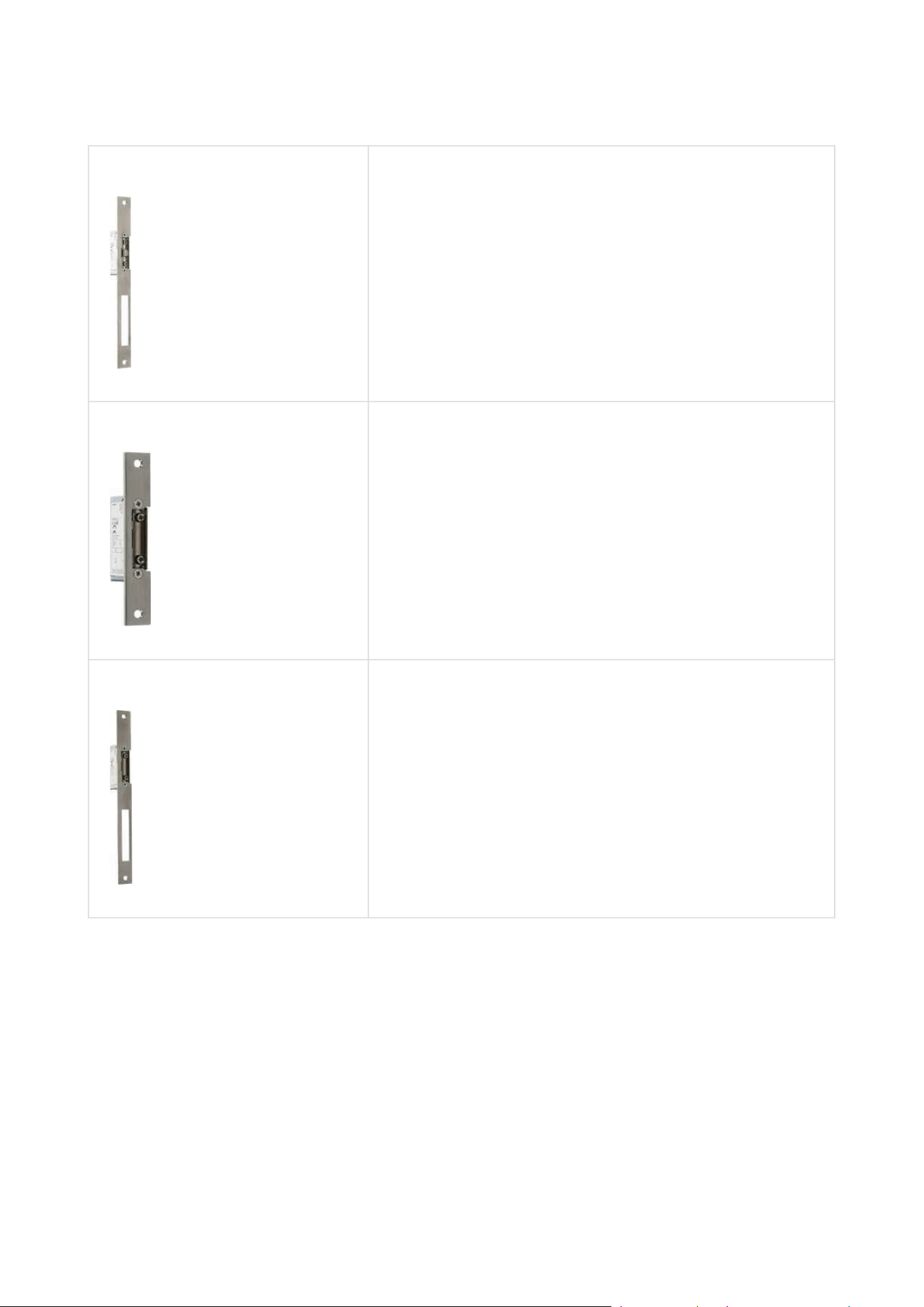
Part No. 11202104 Mini electronic doorstrike series 5 - door signaling
electric opener designed for door frame installation
intended for such narrow profiles as aluminum, wood
or PVC in particular
including a door state monitoring micro switch: open/
closed
short sheet metal front cover version (130 mm)
16 mm width
Part No. 11202104-L Mini electronic doorstrike series 5 - door signaling,
long
electric opener designed for door frame installation
intended for such narrow profiles as aluminum, wood
or PVC in particular
including a door state monitoring micro switch: open/
closed
long sheet metal front cover version (250 mm)
16 mm width
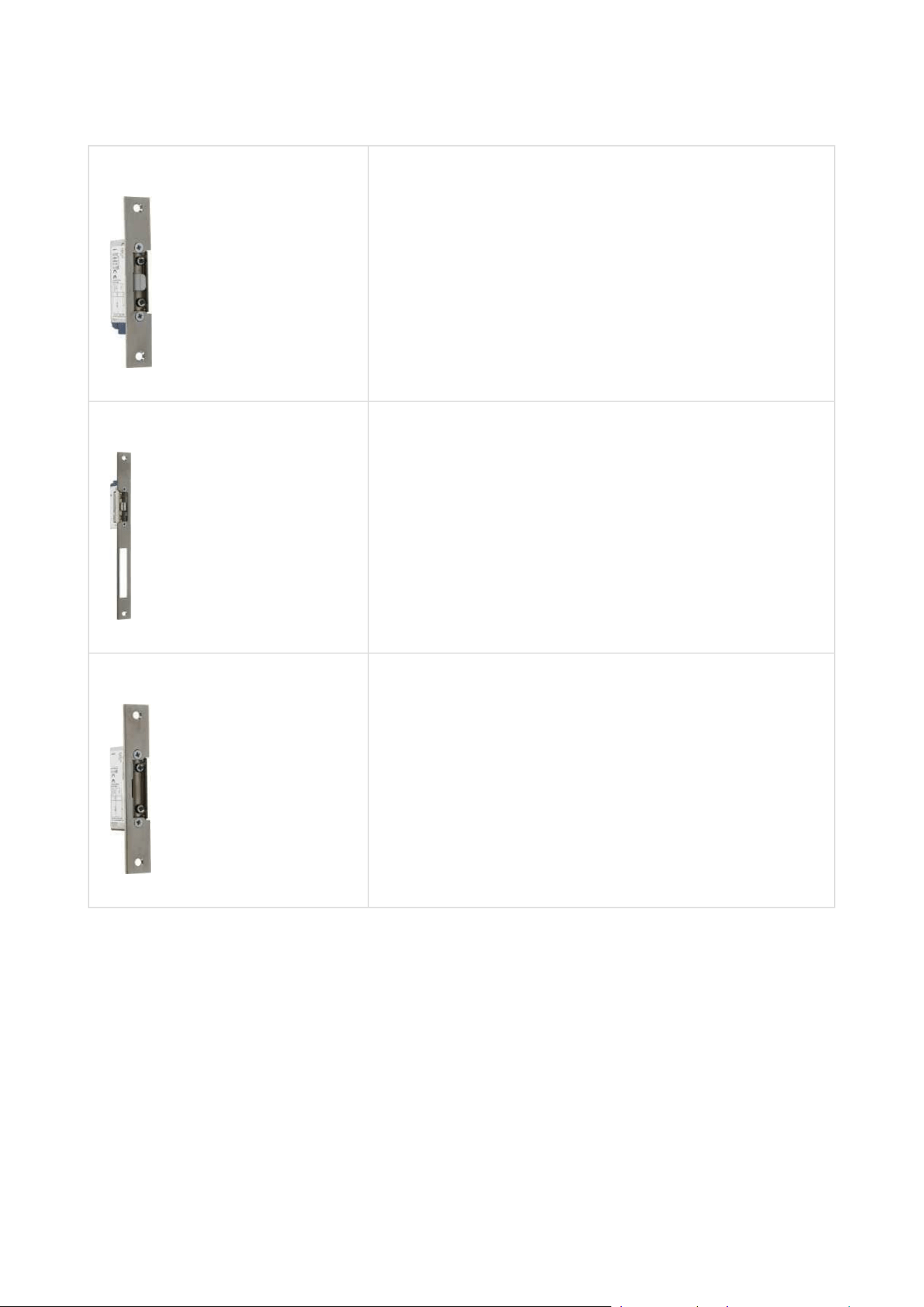
Part No. 11202105 Mini electronic doorstrike series 5 - fail-safe
electric opener designed for door frame installation
intended for such narrow profiles as aluminum, wood
or PVC in particular
under voltage: opener secured, blocked
at voltage interruption: opener unblocked, door can
be opened
short sheet metal front cover version (130 mm)
16 mm width
Installation manual 2N® IP Verso 2.0
47 / 213
•
•
•
•
•
•
•
•
•
•
•
•
•
•
•
•
•
•
•
•
•
Part No. 11202105-L Mini electronic doorstrike series 5 - fail-safe, long
electric opener designed for door frame installation
intended for such narrow profiles as aluminum, wood
or PVC in particular
under voltage: opener secured, blocked
at voltage interruption: opener unblocked, door can
be opened
long sheet metal front cover version (250 mm)
16 mm width
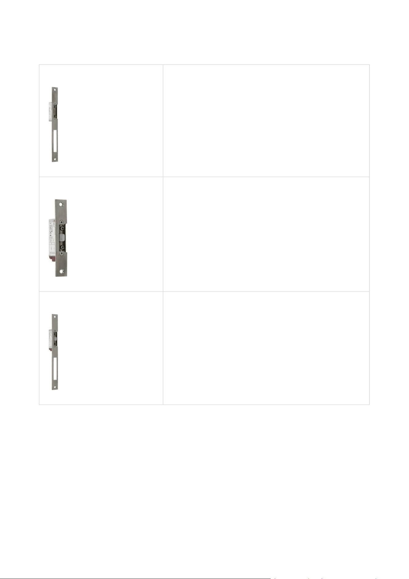
Part No. 11202106 Mini electronic doorstrike series 5 - fail-safe and
door signaling
electric opener designed for door frame installation
intended for such narrow profiles as aluminum, wood
or PVC in particular
under voltage: opener secured, blocked
at voltage interruption: opener unblocked, door can
be opened
short sheet metal front cover version (130 mm)
16 mm width
Part No. 11202106-L Mini electronic doorstrike series 5 - fail-safe and
door signaling, long
electric opener designed for door frame installation
intended for such narrow profiles as aluminum, wood
or PVC in particular
under voltage: opener secured, blocked
at voltage interruption: opener unblocked, door can
be opened
long sheet metal front cover version (250 mm)
16 mm width
Installation manual 2N® IP Verso 2.0
48 / 213
•
•
•
•
•
•
•
•
•
•
•
•
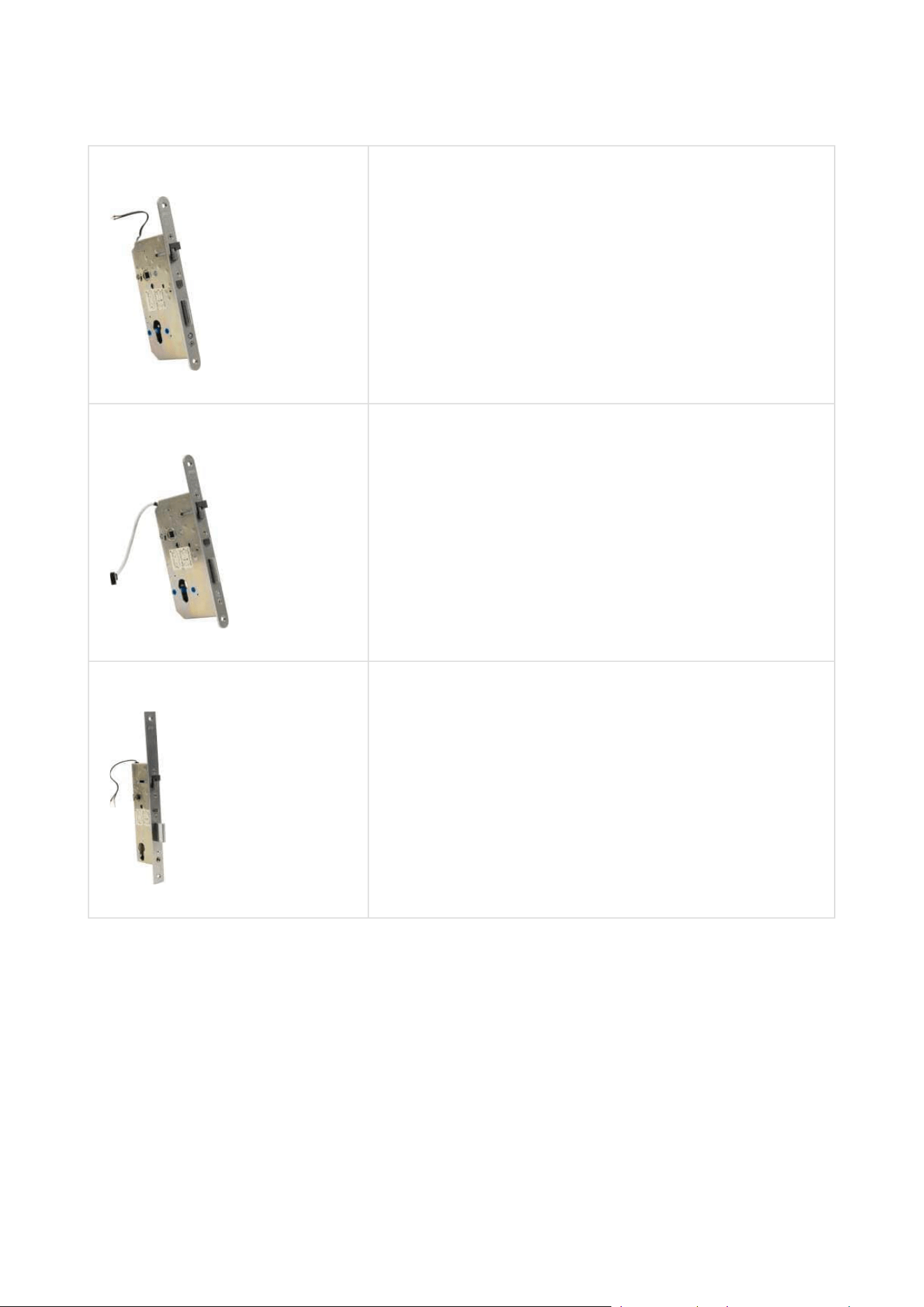
Part No. 11202201 Electromechanical lock SAM 7255
72/55 self-locking lock with panic function
A key is necessary for door opening from the outside
(or an electric pulse from a connected 2N IP
intercom / reader).
convenient solution for emergency exits
Part No. 11202201-M Electromechanical lock SAM 7255 with monitoring
72/55 self-locking lock with panic function
A key is necessary for door opening from the outside
(or an electric pulse from a connected 2N IP
intercom / reader).
convenient solution for emergency exits
Part No. 11202202 Electromechanical lock SAM 9235
92/35 self-locking lock with panic function
A key is necessary for door opening from the outside
(or an electric pulse from a connected 2N IP
intercom / reader).
convenient solution for emergency exits

Installation manual 2N® IP Verso 2.0
49 / 213
•
•
•
•
•
•
•
•
•
•
Part No. 11202202-M Electromechanical lock SAM 9235 with monitoring
92/35 self-locking lock with panic function
A key is necessary for door opening from the outside
(or an electric pulse from a connected 2N IP
intercom / reader).
convenient solution for emergency exits
Part No. 11202301 Cable protector FX290
Provides secure passage and protection of the supply
cable between the door frame and the door leaf.
290 mm length
Part No. 11202302 Cable protector FX510
Provides secure passage and protection of the supply
cable between the door frame and the door leaf.
510 mm length
Installation manual 2N® IP Verso 2.0
50 / 213
•
•
•
•
•
•
•
•
•
•
•
•
•
•
•
•
Part No. 11202303 Cable protector FX300G
Provides secure passage and protection of the supply
cable between the door frame and the door leaf.
440 mm length
Part No. 11202304 Cable protector FX500G
Provides secure passage and protection of the supply
cable between the door frame and the door leaf.
640 mm length
Part No.11202203 Supply cable with 14-core connector
6000 mm length
Conductor cross section: 14 × 0.22 mm
Terminated with a connector on one side
Designed for 11202201-M and 11202202-M locks
Part No. 11202107 Maglock MEX100
used as a door holding supplement, not replacing the
lock
consists of two parts: supplied part and counterpart
under voltage: door cannot be opened
at voltage interruption: magnets get disconnected,
door opens

Installation manual 2N® IP Verso 2.0
51 / 213
•
•
•
•
•
•
•
•
•
•
•
Part No. 11202501 Magnetic handle P300RP
fully replaces a mortise lock and handle
under voltage: door cannot be opened
at voltage interruption: magnets get disconnected,
door opens
suitable for wooden, metal and glass doors
Part No. 11202401 ED100
low energy simple door operator
contactless operation
can be interconnected with a motion sensor and
electronic access control system
applicable for right / left doors
in / out opening versions
Installation manual 2N® IP Verso 2.0
52 / 213
•
•
•
•
•
•
•
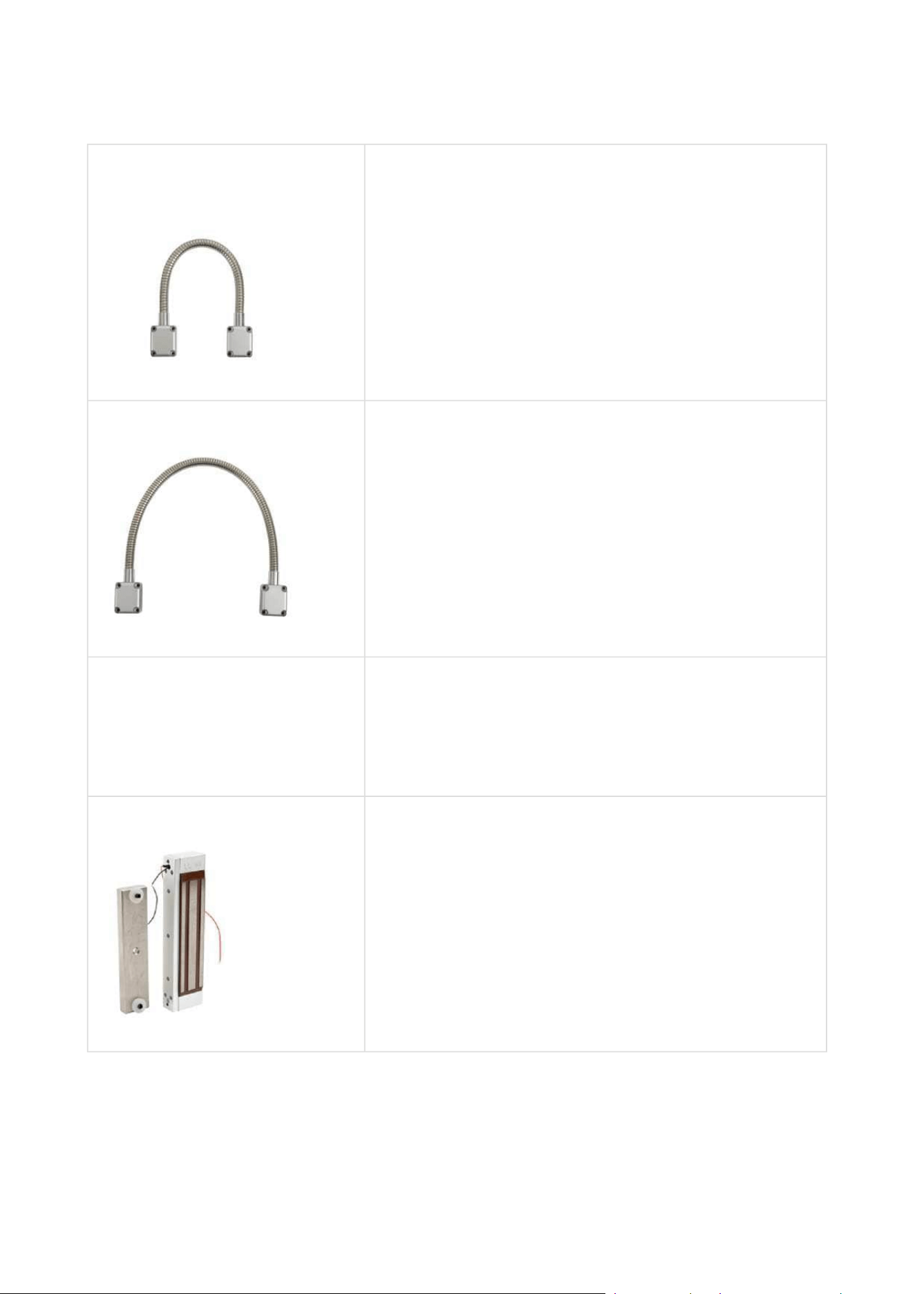
Power Supply
2N Part No.
91378100E
2N Part No.
91378100US
Axis Part No.
01403-001
PoE injector – with EU cable (91378100E)
PoE injector – with US cable (91378100US)
For intercom power supply viaan Ethernetcable where PoE switch is
unavailable.
2N Part
No.91341481E
Stabilized 12 V / 2 A power supply needs to be used where no PoE is
available.
2N Part
No.932928
12 V transformer
For 230 V mains voltage.
For external power supply of the lock with 12 V AC voltage.
•
Tip
FAQ: Electric locks – Difference between locks in 2N IP intercom accessories
Installation manual 2N® IP Verso 2.0
53 / 213
•
•
•
•
•
•
•
•
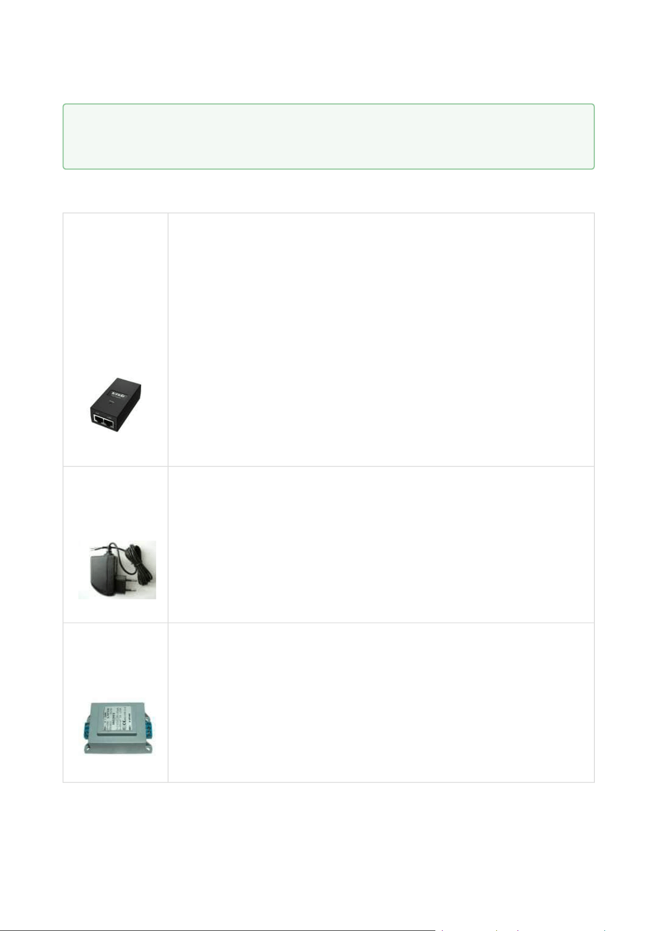
Two-Wire Connection
2N Part No. 9159014EU/UK
2N Part No. 9159014US
Axis Part No. 01404-001
2N 2Wire
(set of 2 adaptors and power source for EU/US/UK)
The 2N
2Wire converter allows you to use the existing
wiring (2 wires) from your original doorbell or door
intercom to connect any IP device. You don’t have to
configure anything, all you need is one 2N
2Wire unit
at each cable end and a power supply connected to at
least one of these units.
The 2N
2Wire unit then providesPoEpower not only
to the second converter, but also to all the other
connected IP end devices.
2N Part No. 1120103
Axis Part No. 02318-001
NVT PoLRE LPC Switch
with 2 adapters
IP solutions with analogue cabling
2N Part No. 1120104
Axis Part No. 02319-001
NVT PhyLink Adapter
pack of 6 adapters
Installation manual 2N® IP Verso 2.0
54 / 213
•
•
•
•
•
•
•
•
•
•
•
•
•
•
•
•
•
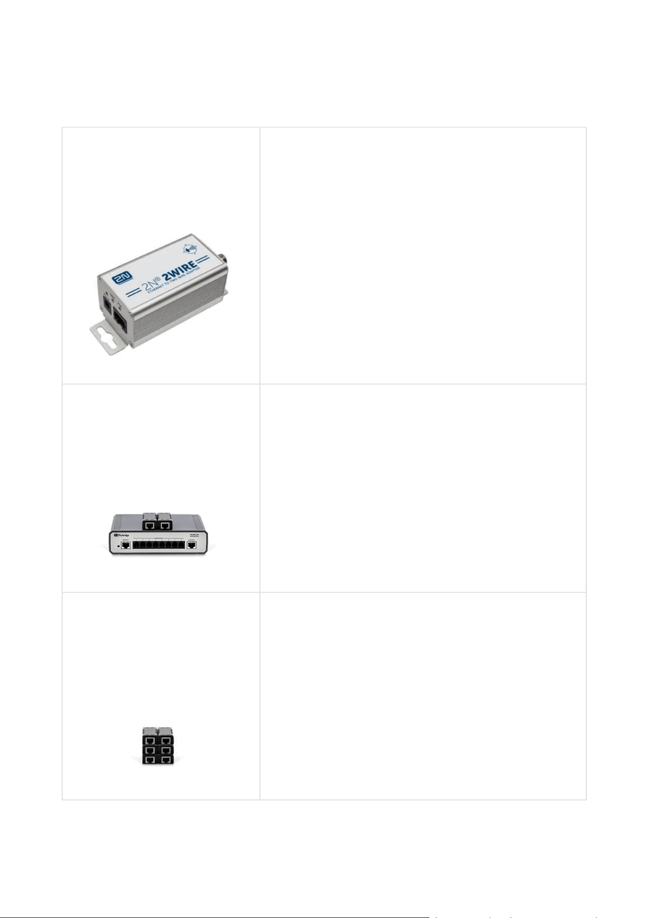
RFID 13 MHz
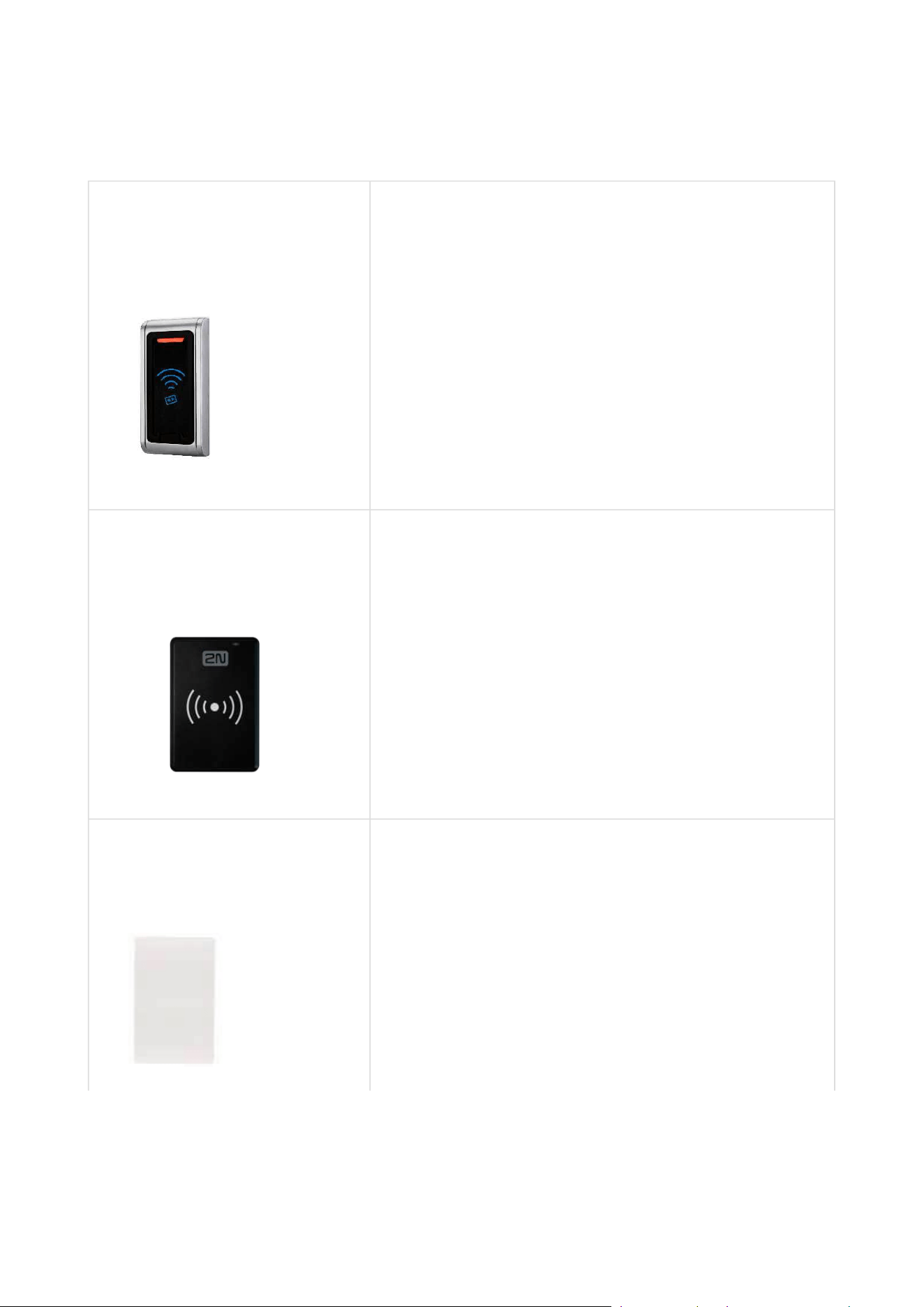
2N Part No.9159031
Axis Part No. 01390-001
External 13.56 MHz MIFARE RFID card reader,
Wiegand
Secondary reader for connection to an internal reader.
Allows for card entry control from both sides of the
door. IP68 cover, also suitable for exteriors. Reads the
following cards:
ISO14443A (MIFARE, MIFARE DESFire)
PicoPass (HID iClass)
FeliCa
ST SR(IX)
2NMobile Key
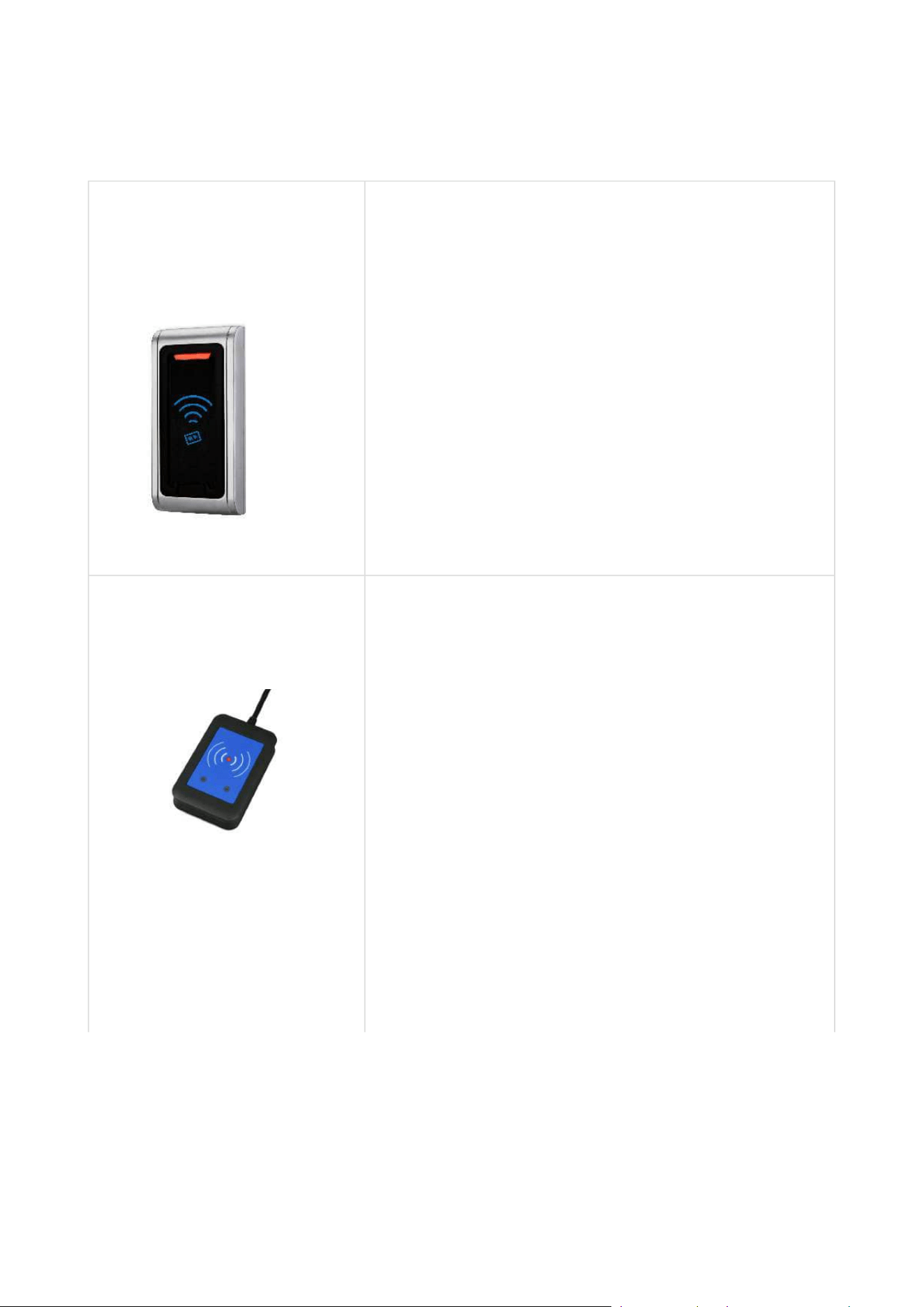
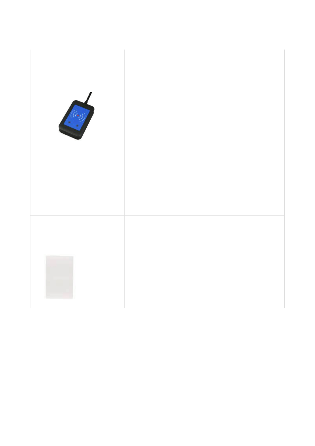
2N Part No. 9137421E
Axis Part No. 01400-001
External RFID Reader 13.56 MHz, 125 kHz + NFC/
HCE (USB interface)
External RFID card reader for connection to a PC via a
USB interface. Suitable for system administration and
adding 13.56 MHz/125 kHzcards and NHC/HCE
supporting Android platform devices using the 2N IP
intercom web interface or 2N Access Commander
application. Suitable for MIFARE DESFire card upload
to the2NPICard Commanderencryption application.
It reads the same types of cards and devices as card
readers in 2N IP intercoms:
125 kHz
EM4xxx
13.56 MHz
ISO14443A (MIFARE, MIFARE
DESFire)
PicoPass (HID iClass)
FeliCa
ST SR(IX)
2NMobile Key
Installation manual 2N® IP Verso 2.0
55 / 213
•
•
•
•
•
•
•
•
•
•
•
•
2N Part No.9137424E
Axis Part No. 01527-001
External secured RFID Reader 13.56 MHz, 125 kHz +
NFC/HCE (USB interface)
External secured RFID card reader for connection to
PC using a USB interface. Suitable for system
administration and adding 13.56 MHz, 125 kHzcards
and NFC/HCE supporting Android platform devices
using the 2N IP intercom web interface or 2N Access
Commander application. Suitable for MIFARE DESFire
card upload to the 2NPICard Commanderencryption
application. It reads the same types of cards and
devices as card readers in 2N IP intercoms:
125 kHz
EM4xxx
13.56 MHz
ISO14443A (MIFARE, MIFARE DESFire)
PicoPass (HID iClass)
FeliCa
ST SR(IX)
2NMobile Key
HID SE (Seos, iClass SE, MIFARE SE)
2N Part No.9134173
Axis Part No. 01384-001
MIFARE Classic, 1k RFID card, 13.56 MHz
Installation manual 2N® IP Verso 2.0
56 / 213
•
•
•
•
•
•
•
•
•
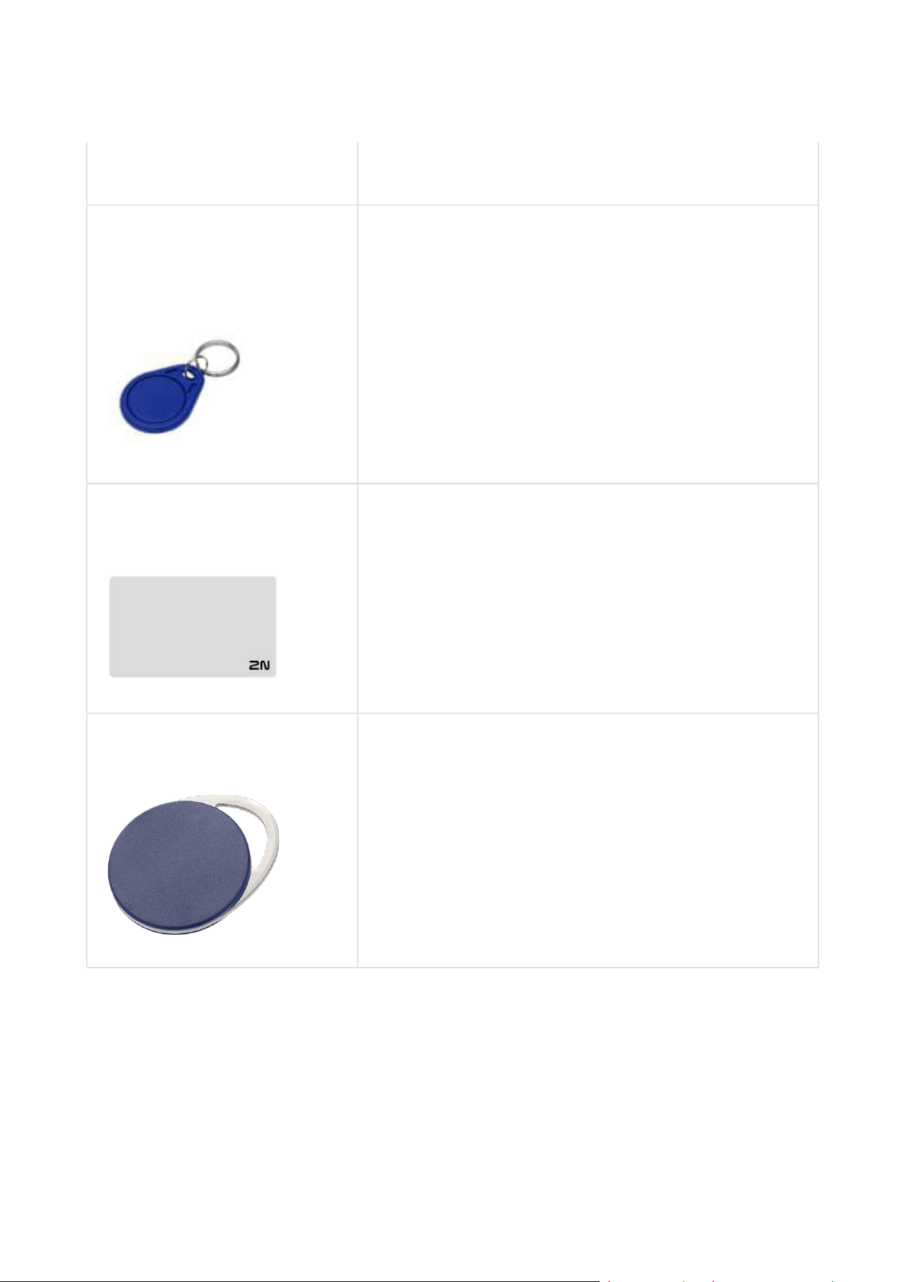
2N Part No.9134174
Axis Part No. 01385-001
MIFARE Classic, 1k RFID fob, 13.56 MHz
2N Part No.11202601
Axis Part No.02787-001
2NRFID card Mifare Desfire EV3 4K 13.56MH 10 pcs
10 pcs per package
MIFARE DESFire EV3 (ISO/IEC14443A)
Suitable for data encryption in2NPICard
Commander
2N Part No.11202602
Axis Part No.02788-001
2NRFID fob Mifare Desfire EV3 4K 13.56MHz 10 pcs
10 pcs per package
MIFARE DESFire EV3 (ISO/IEC14443A)
Suitable for data encryption in2NPICard
Commander
Installation manual 2N® IP Verso 2.0
57 / 213
•
•
•
•
•
RFID 125 kHz
2N Part No. 9159030
Axis Part No. 01389-001
External 125 kHz RFID card reader
Secondary reader for connection to an internal
reader. Allows for card entry control from both sides
of the door. IP67 cover, also suitable for exteriors.
Reads EM4xxx cards.
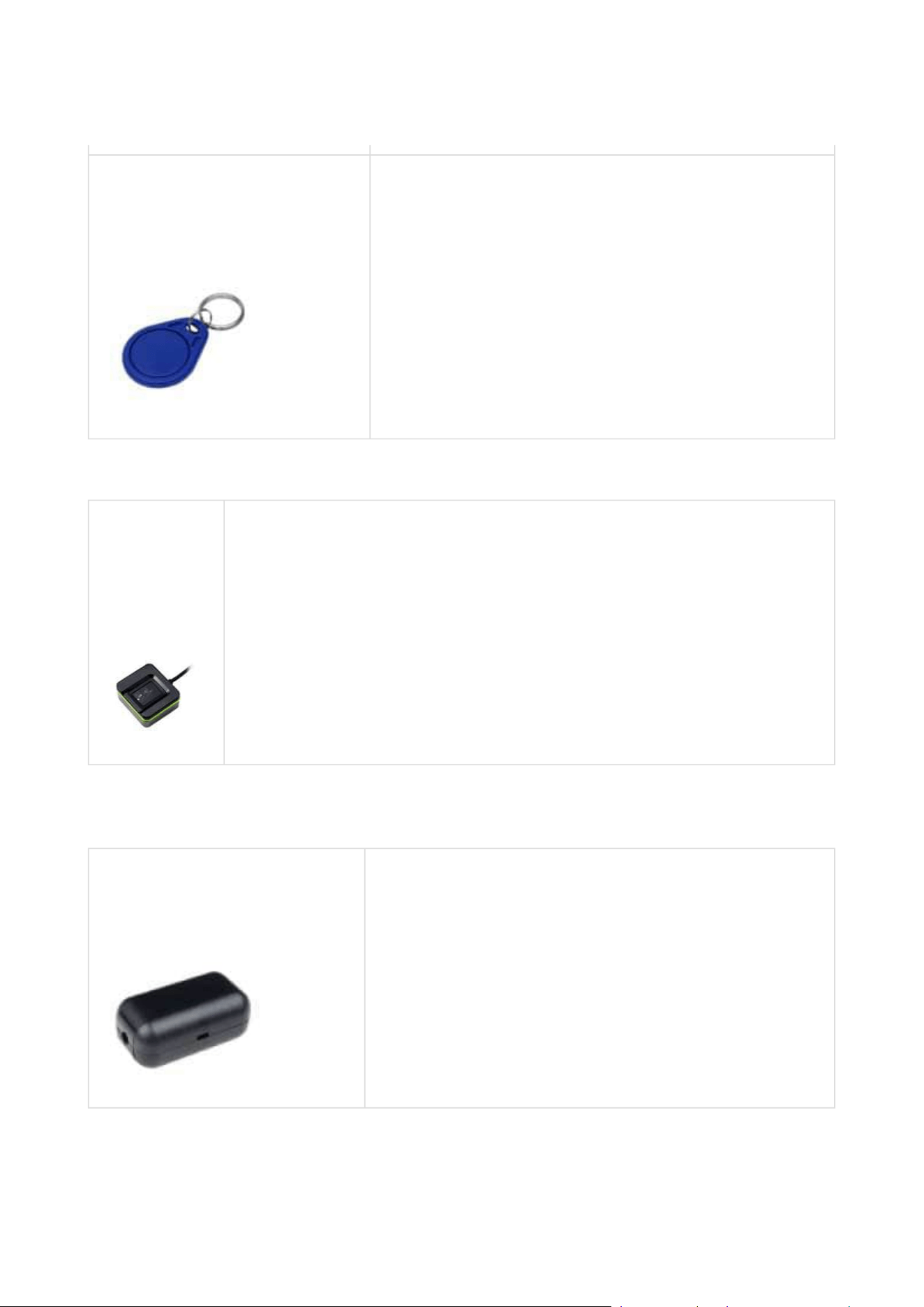
2N Part No.9137420E
Axis Part No. 01399-001
USB RFID card reader, 125 kHz
External RFID card reader for connection to a PC using
a USB interface. Suitable for system management and
addition of EM4xxx cards via the PC application, 2N
Access Commander.
2N Part No.9134165E
Axis Part No. 01395-001
RFID card, type EM4100, 125 kHz
Installation manual 2N® IP Verso 2.0
58 / 213
•
•
•
•
2N Part No.9134166E
Axis Part No. 01396-001
RFID fob, type EM4100, 125 kHz
Biometry
2N Part No.
9137423E
Axis Part No.
01401-001
2N IP intercom – external fingerprint reader (USB interface)
External Switches
2N Part No.9159010
Axis Part No. 01386-001
2NSecurity Relay
A handy add-on that significantlyenhances door entry
security as it prevents tampering with the intercom
and forced opening of the lock. To be installed
between the intercom and lock, powered by the
intercom.
Installation manual 2N® IP Verso 2.0
59 / 213
•
•
•
•
2N Part No.9137410E
Axis Part No. 01397-001
External IP Relay – 1 output
Standalone IP device controlled by HTTP commands
sent by the 2N IP intercom, which can thus control
devices via unlimited distances.
2N Part No. 9137411E
Axis Part No. 01398-001
External IP Relay – 4 outputs, PoE
Standalone IP device controlled by HTTPcommands
sent by the 2N IP intercom, which can thus control
devices via unlimited distances.
Installation manual 2N® IP Verso 2.0
60 / 213
•
•
•
•
•
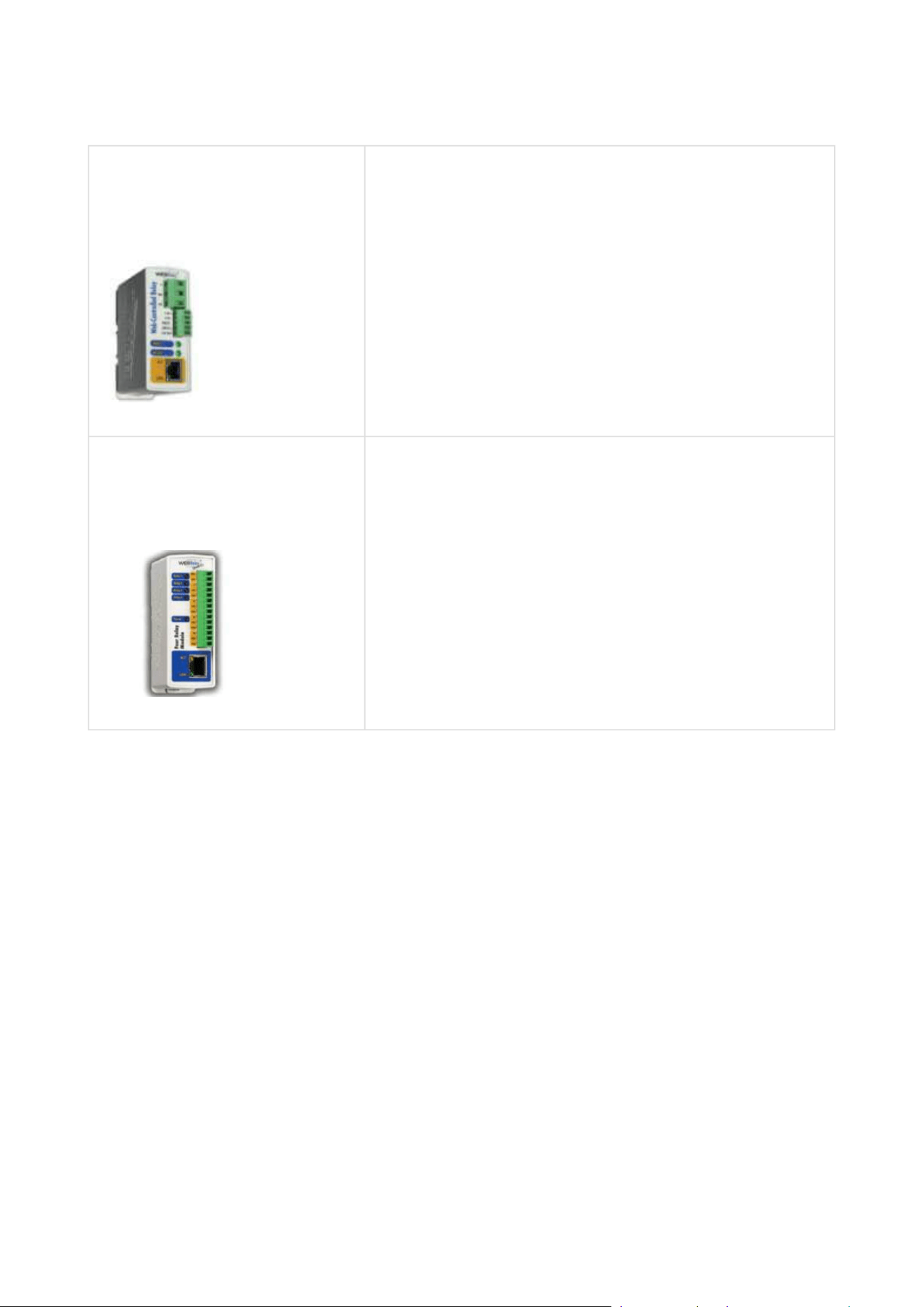
2N Part No. 9160501
Axis Part No. 0820-001
AXIS A9188 Network I/O relay module
Lift control relay module for up to 8 floors
Induction Loop
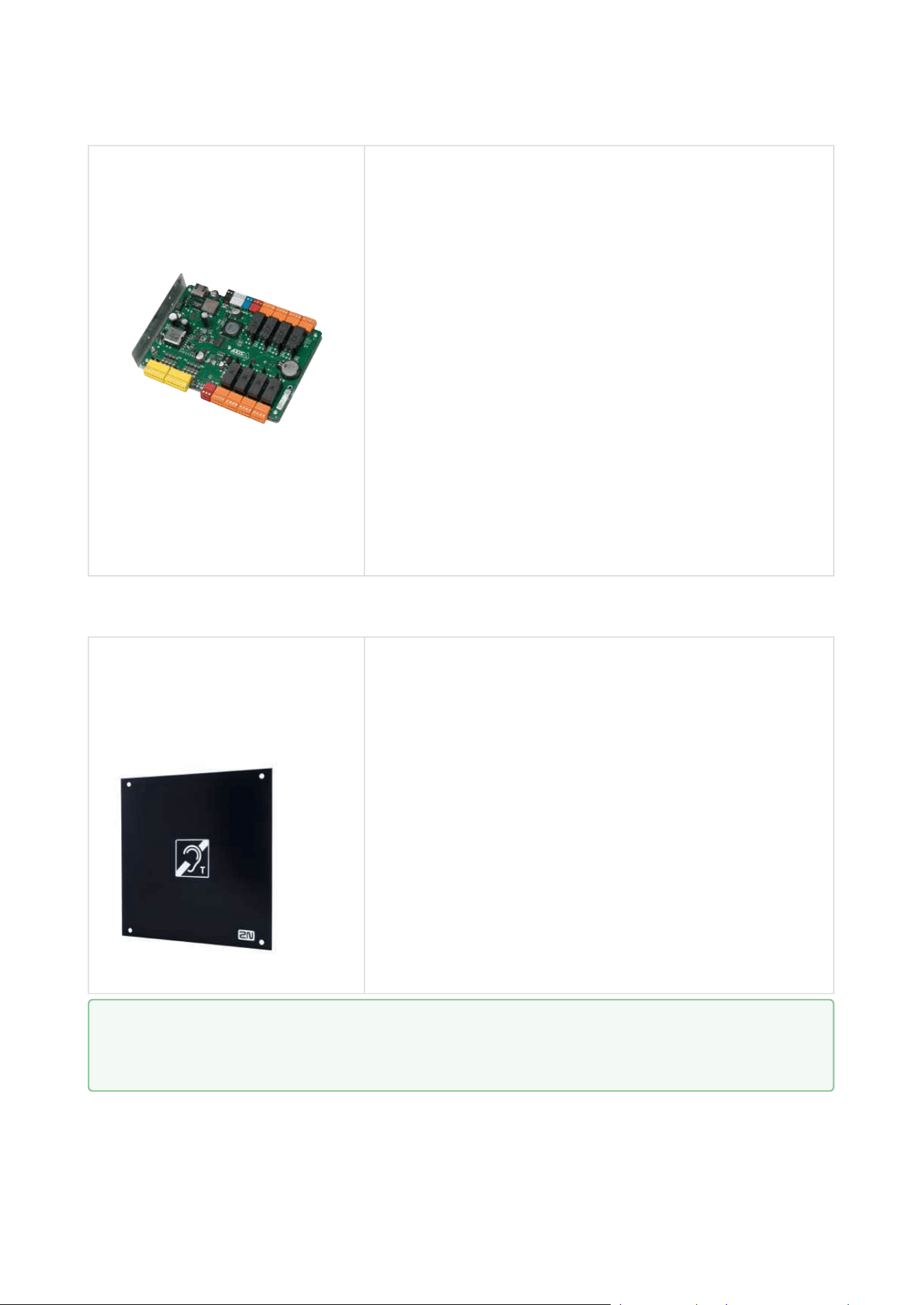
2N Part No.9155043
Axis Part No. 01265-001
Induction loop module – antenna
The external antenna boosts the range of usability of
the induction loop so that a hearing impaired user
wearing a hearing aid with telecoil can receive the
audio signal over a wider area. It has to be used with
Part No.9155041. A 40 cm long interconnecting cable
is included.
Dimensions: 233 (W) x 233 (H) mm
•
Tip
FAQ: Induction loop – How to connect it with 2N IP intercom
Installation manual 2N® IP Verso 2.0
61 / 213
•
•
•
•
•
Sensors and Switches
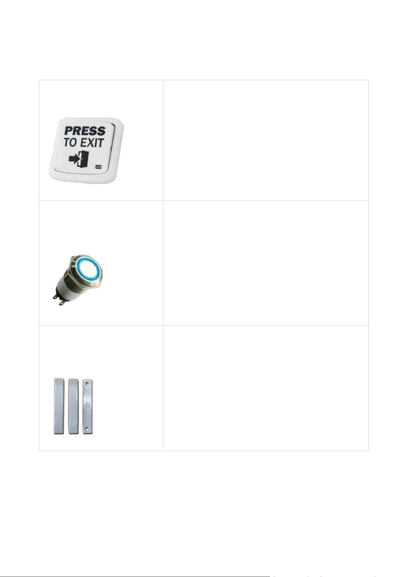
2N Part No. 9159013
Exit button
A button for logic input connection for opening a door
inside a building.
2N Part No. 9154004
Axis Part No. 01479-001
Water-proof metal button
2N Part No. 9159012
Axis Part No. 01388-001
Magnetic door contact
Door installation set that enables the status of door
opening to be ascertained. Used when the intercom is
used for door protection to detect whether the door is
open or opened by violence.
Installation manual 2N® IP Verso 2.0
62 / 213
•
•
•
•
Additional Modules
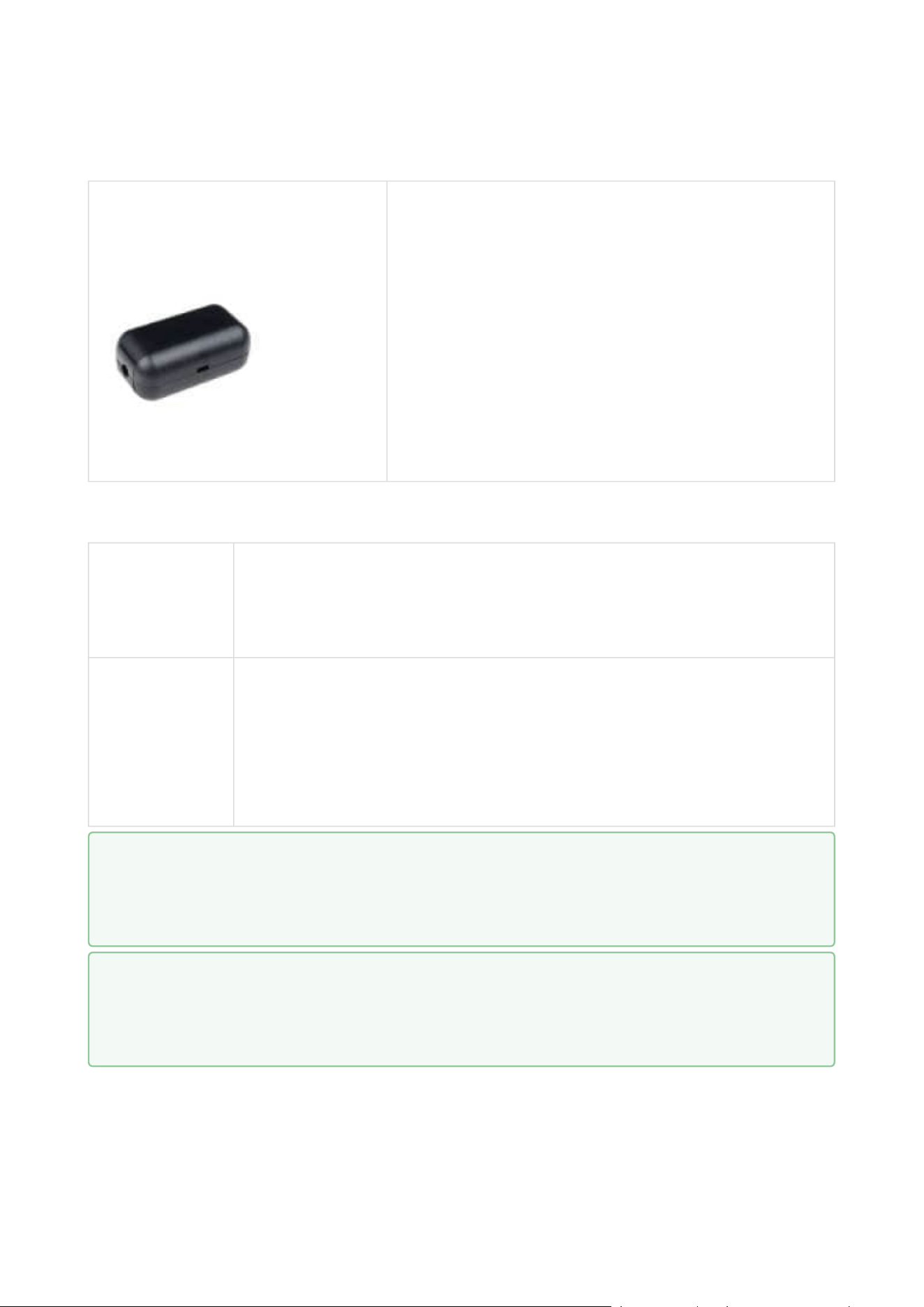
2N Part No. 9159011
Axis Part No. 01387-001
The 2N Wiegand Isolator is designed for galvanic
isolation of two devices separately powered and
interconnected via the Wiegand bus. The 2N
Wiegand Isolator protects the interconnected
devices against communication errors and/or
damage.
License
2N Part No.
9137909
Gold
Includes Enhanced Video, Enhanced Integration and Lift Control
licenses
2N Part No.
9137910
Axis Part No.
01381-001
InformaCast
•
Tip
Refer to the Configuration Manual for 2N IP Intercoms, Subs.3.2 Function
Licensing for license details.
•
Tip
For more accessories and specific advice please contact your local distributor of
2N products.

Installation manual 2N® IP Verso 2.0
63 / 213
1.2 Terms and Symbols
The following symbols and pictograms are used in the manual:
•
Safety
Always abide by this information to prevent persons from injury.
•
Warning
Always abide by this information to prevent damage to the device.
•
Caution
Important informationfor system functionality.
•
Tip
Useful informationfor quick and efficient functionality.
•
Note
Routines or advice for efficient use of the device.

Installation manual 2N® IP Verso 2.0
64 / 213
•
•
•
•
•
•
•
•
2. Description and Installation
Here is what you can find in this section:
2.1 Before You Start
2.2 Mechanical Installation
2.3 Electric Installation
2.4 Extending Module Connection
2.5 Completion
2.1 Before You Start
Product Completeness Check
Before installation, check whether the purchased product package complies with the contents
below.
The2N
®
IP Verso 2.0packageshouldcomply with the following content:
1x2N
®
IP Verso 2.0
1x Quick Guide
1x Certificate of ownership
2.2 Mechanical Installation
Mounting Types Overview
There are two ways how to install the device: flush mounting into classic bricks / plasterboard
and surface (wall) mounting.
2.2.1 Flush Mounting
2.2.2 Surface Mounting
Mounting Backplate Installation
2.2.3 Example of Mounting Plate Installation
Tamper and I/O Modules, Module Dimensions
2.2.4 Tamper and I/O Modules
2.2.5 Module Dimensions

Installation manual 2N® IP Verso 2.0
65 / 213
•
•
Note
You can assemble multiple units in all mounting types.
The recommended standard installation height is 1350 mm from the ground to the
device camera level. The installation height may vary depending on the device use.
•
•
•
•
Caution
Before starting the mechanical installation on a selected place, make sure
carefully that the preparations connected with it (drilling, wall cutting) cannot
damage the electrical, gas, water and other existing wires and pipes.
The warranty does not apply to the product defects and failures arisen as a result
of improper mounting (in contradiction herewith). The manufacturer is neither
liable for damage caused by theft within an area that is accessible after the
attached electric lock is switched. The product is not designed as a burglar
protection device except when used in combination with a standard lock, which
has the security function.
When the proper mounting instructions are not met, water might get in and
destroy the electronics. It is because the communicator circuits are under
continuous voltage and water infiltration causes an electro-chemical reaction. The
manufacturer’s warranty shall be void for products damaged in this way!
Do not remove the plastic film on the seal inside the frame, otherwise water may
leak and damage the electronic components.

Installation manual 2N® IP Verso 2.0
66 / 213
General Mounting Principles
•
•
Tip
Select flush mounting where possible to make your product elegant looking, more
vandal resistant and more secure.
You are advised to buy the flush mounting boxes in advance and commission your
building company to do the masonry for you. This approach helps you put your
intercom exactly in the vertical position.

Installation manual 2N® IP Verso 2.0
67 / 213
•
•
•
•
•
•
•
•
•
•
•
Caution
Make sure that the diameter of the dowel holes is accurate to avoid falling out of
the dowels! Use the mounting glue to secure the dowels if necessary.
Make sure that the depth of the dowel holes is accurate!
Do not use low-quality dowels to avoid their pulling out of the wall!
Having removed the front panel, make sure that no dirt gets inside the product
(especially onto the sealing surface).
Never turn2N
®
IP Versoto align the box assembly after mounting. Make sure that
the flush mounting boxes have been installed accurately.
Check the plasterboard wall and room interior pressure values. If the difference
between the values is too great (as a result, e.g., of overpressure ventilation),
separate the intercom using, for example, the mounting box enclosed and seal the
cable passage to avoid speaker damage.
Surface mounting may cause problems on places exposed to potential vandalism
(such as public garages, etc.). In this case, use steel anchoring elements instead of
the dowels and screws included in the delivery.
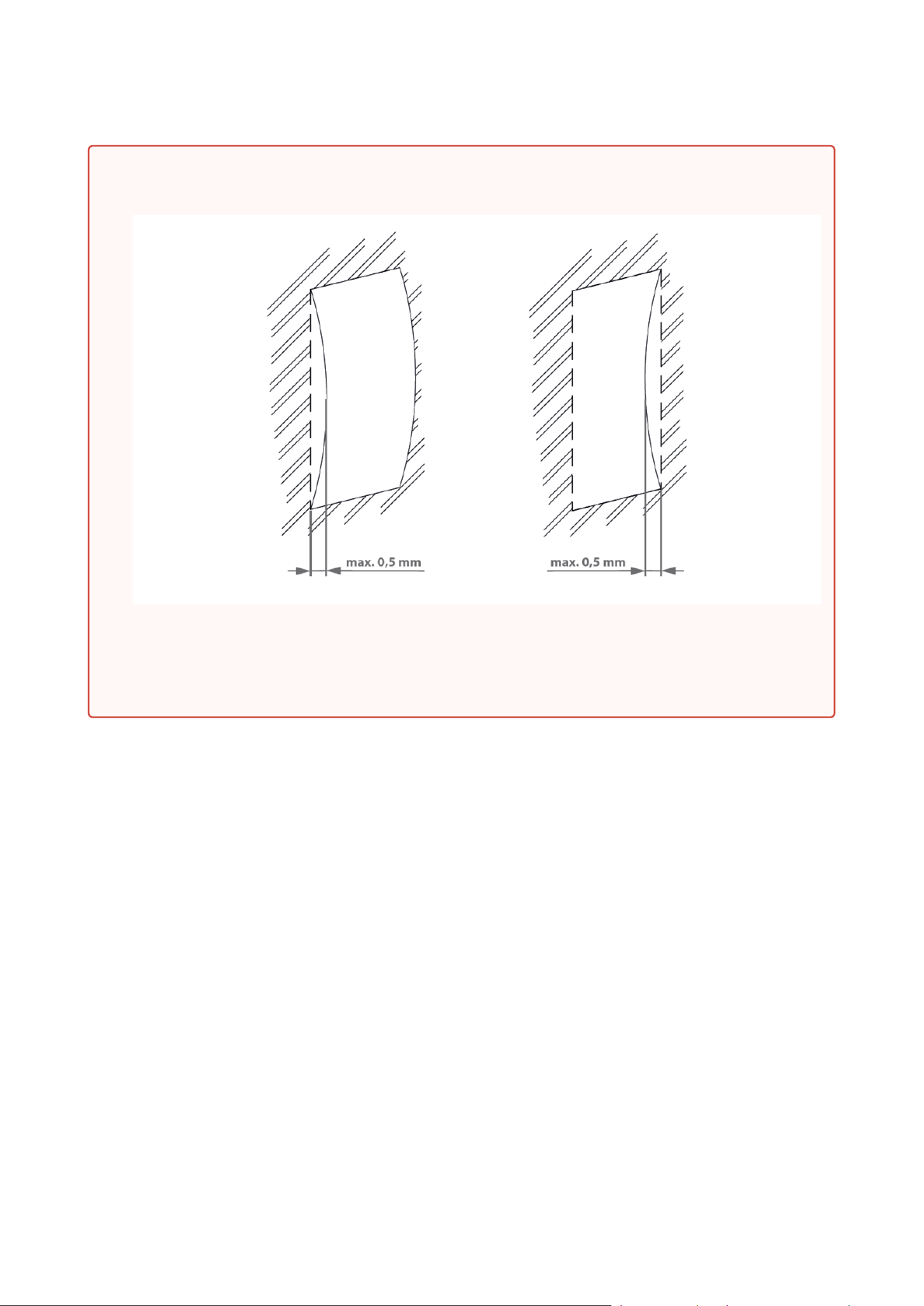
Make sure that the installation surface is perfectly flat with the maximum
inequality of 0.5 mm. (e.g. boards, glass, cut stone, etc). If this is not the case, use a
mounting backplatePart No 9155061–9155067,or level the wall surface.
Always use an installation backplate for uneven installation surfaces.
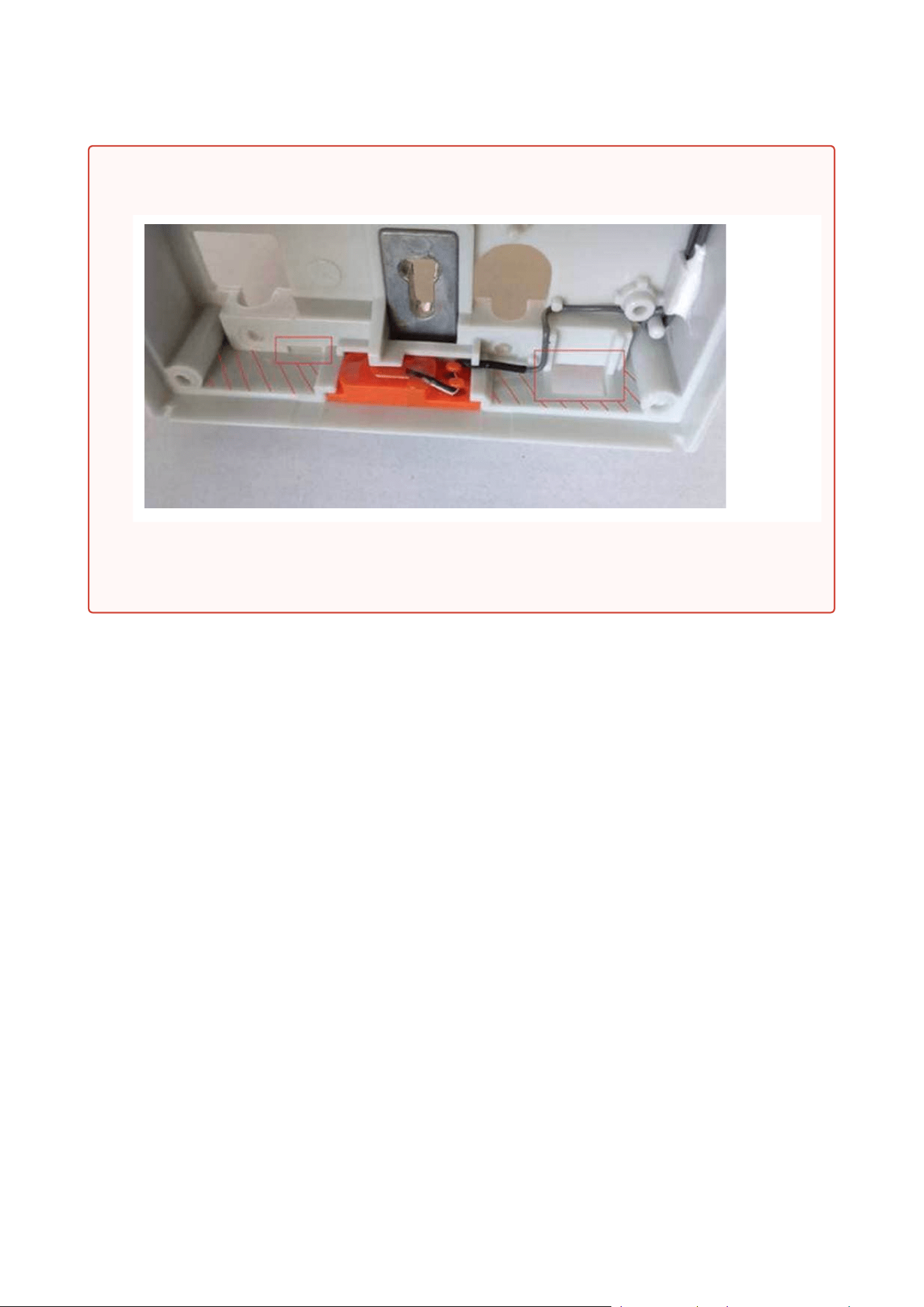
While flush mounting, make sure that the box is installed properly, i.e. with the box
frame on the wall surface. There are snap-off protrusions on both sides of the flush
mounting box to facilitate positioning. Make sure that the frame is placed precisely
onto the flush mounting box off the wall to provide effective sealing and avoid
water penetration into the intercom. Refer to the pictorial instructions inside the
flush mounting box package.
Any intentional mechanical damage (drilling, main unit tampering, etc.) results in a
loss of warranty.
Installation manual 2N® IP Verso 2.0
68 / 213
•
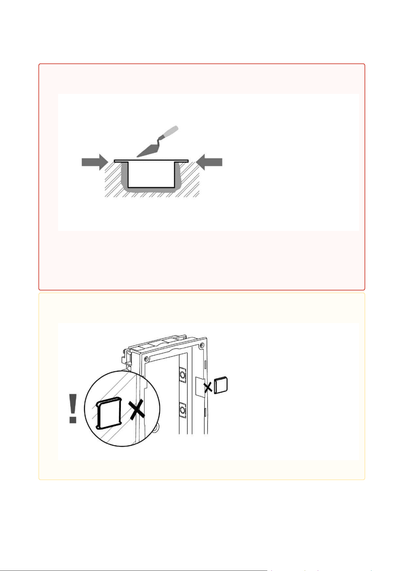
Warning!
It is forbidden to use silicone or any other sealing material on the marked and
hatched places.
Installation manual 2N® IP Verso 2.0
69 / 213
•
Safety
Eliminate the risk of personal injury! Surface mounting is not recommended for
narrow passages or places where people's attention is distracted by something
else. The manufacturer shall not be liable for injuries in such cases!
Installation manual 2N® IP Verso 2.0
70 / 213
•
•
•
•
2.2.1 Flush Mounting
Flush Mounting Types and List of Necessary Components
Flush mounting is used for classic brick or plaster board installation.
Flush mounting – classic bricks
incl. hollow bricks, thermally insulated walls, etc.
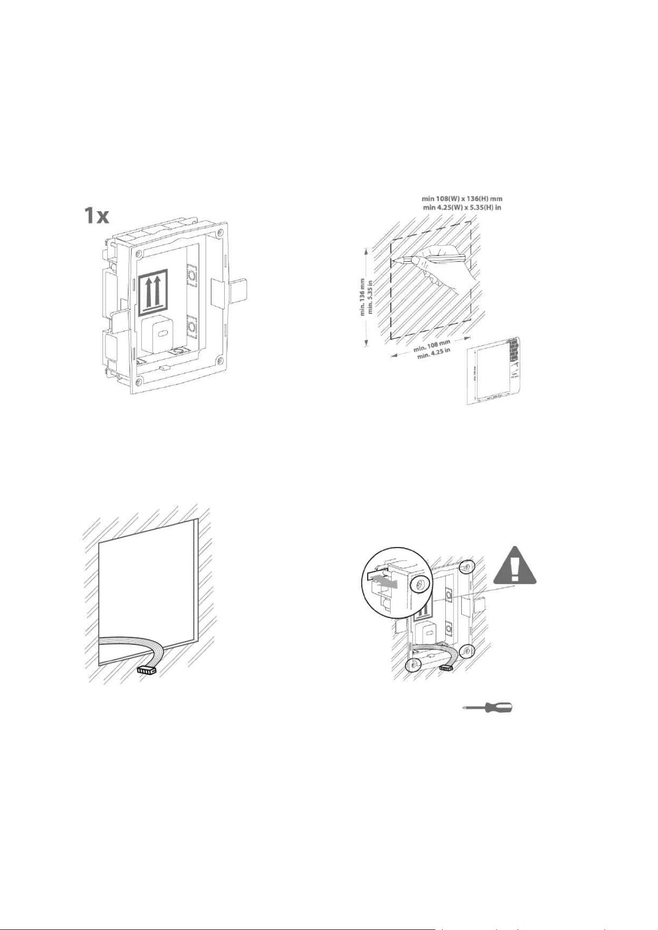
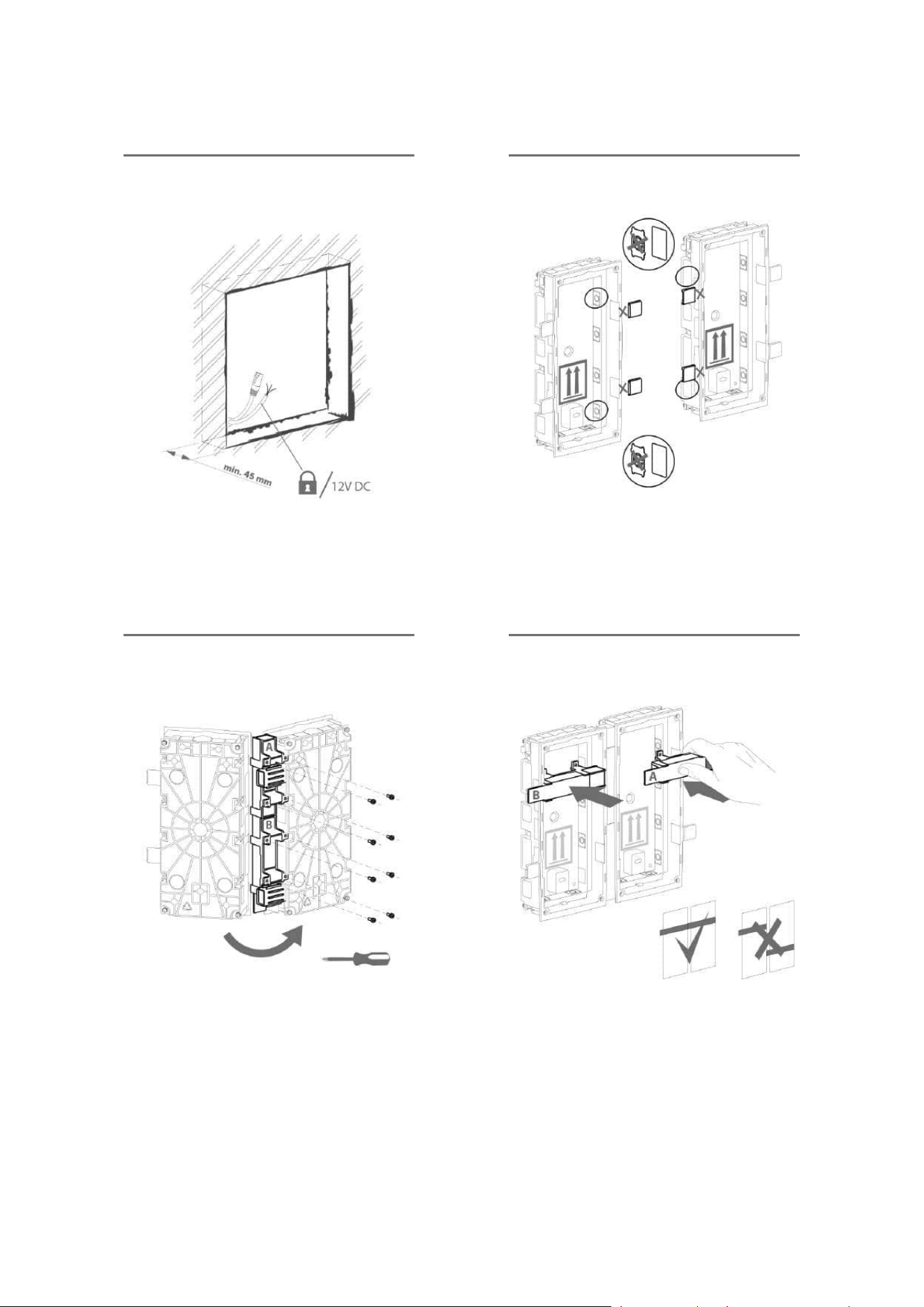
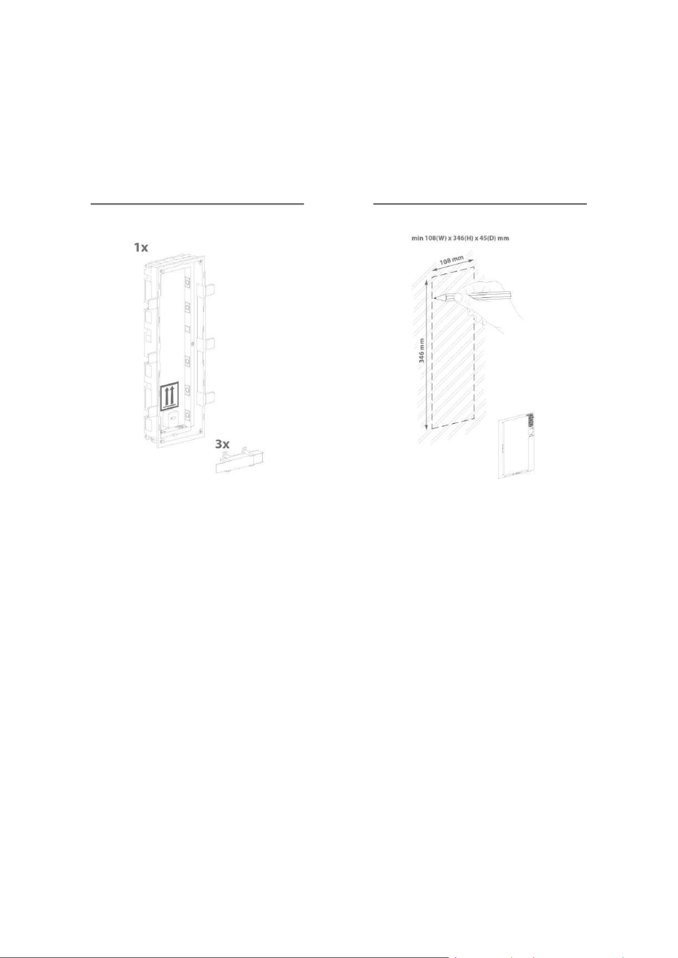
What you need for mounting:
a properly cut hole as instructed in the box package
Plaster, mounting glue, mounting foam or mortar as necessary
2N
®
IP Verso, flush mounting boxes and frames
•
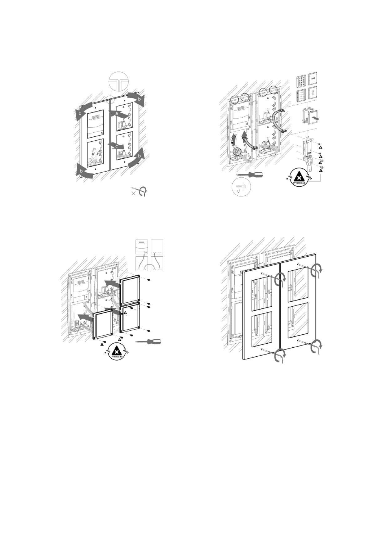
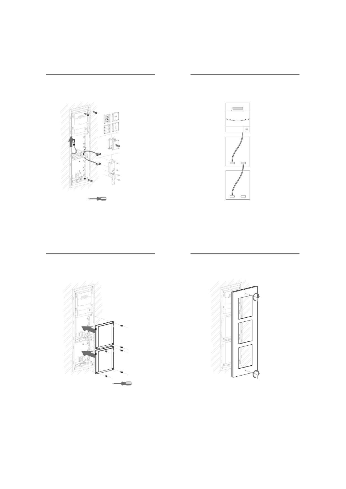
•
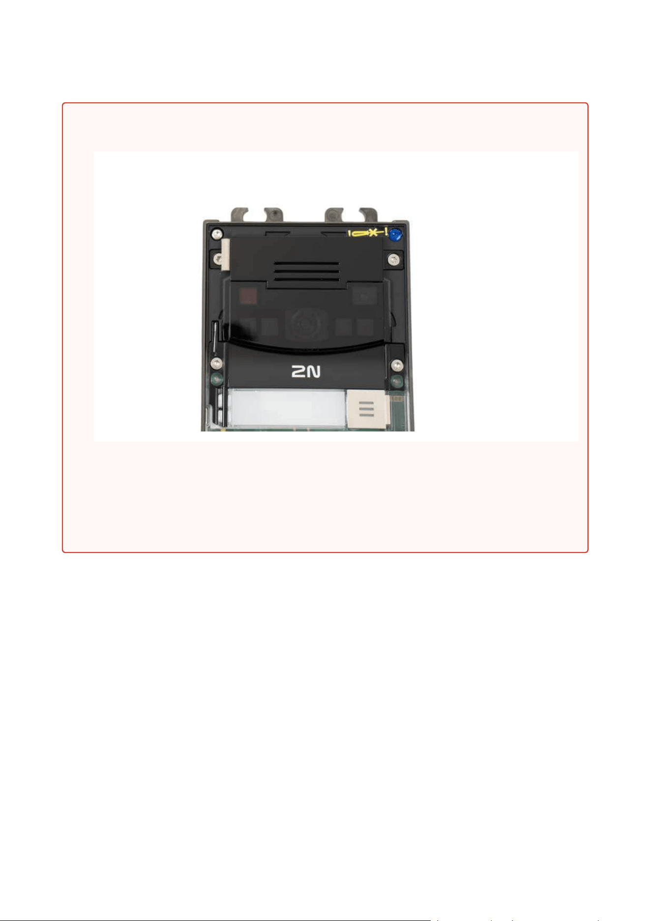
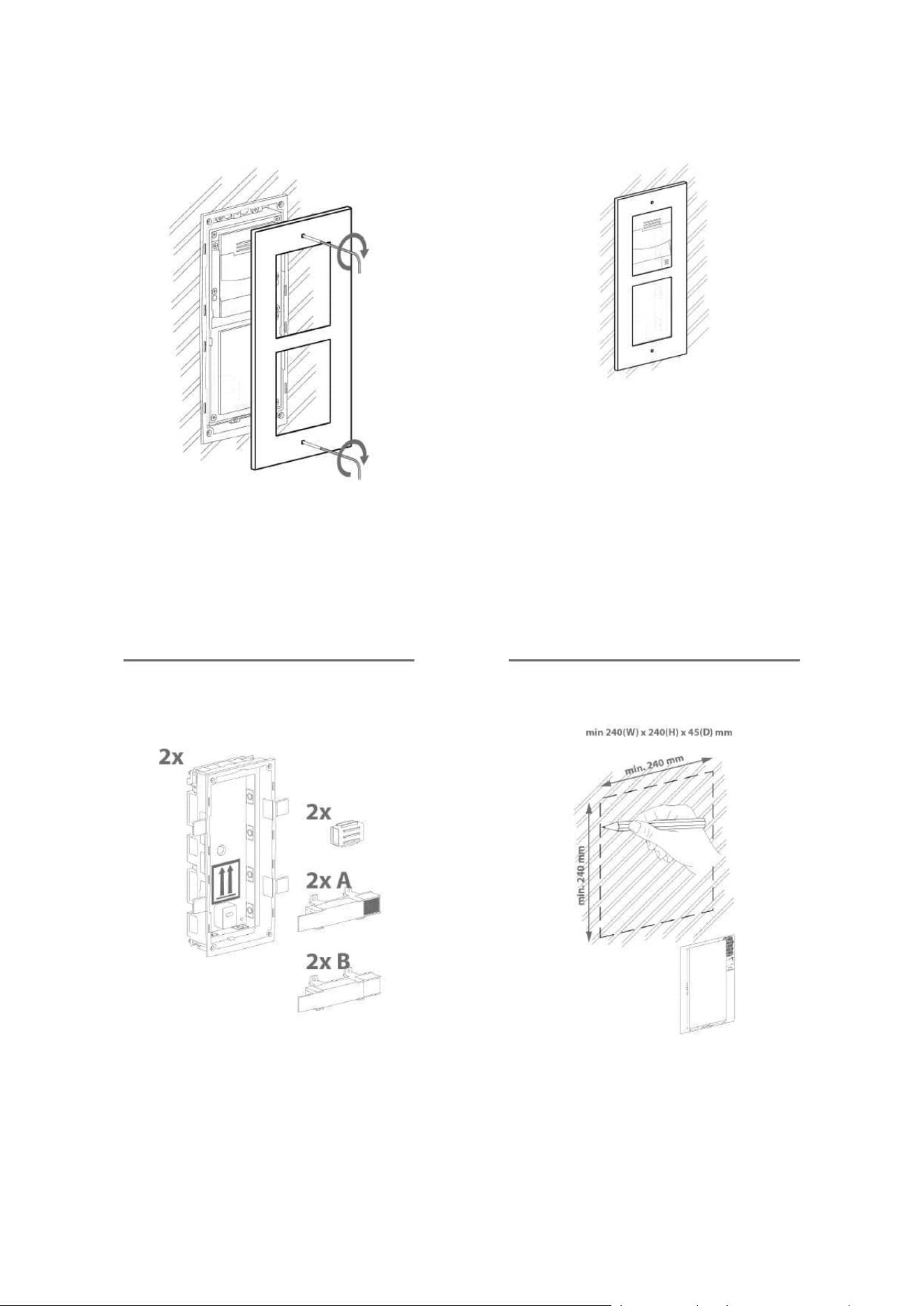
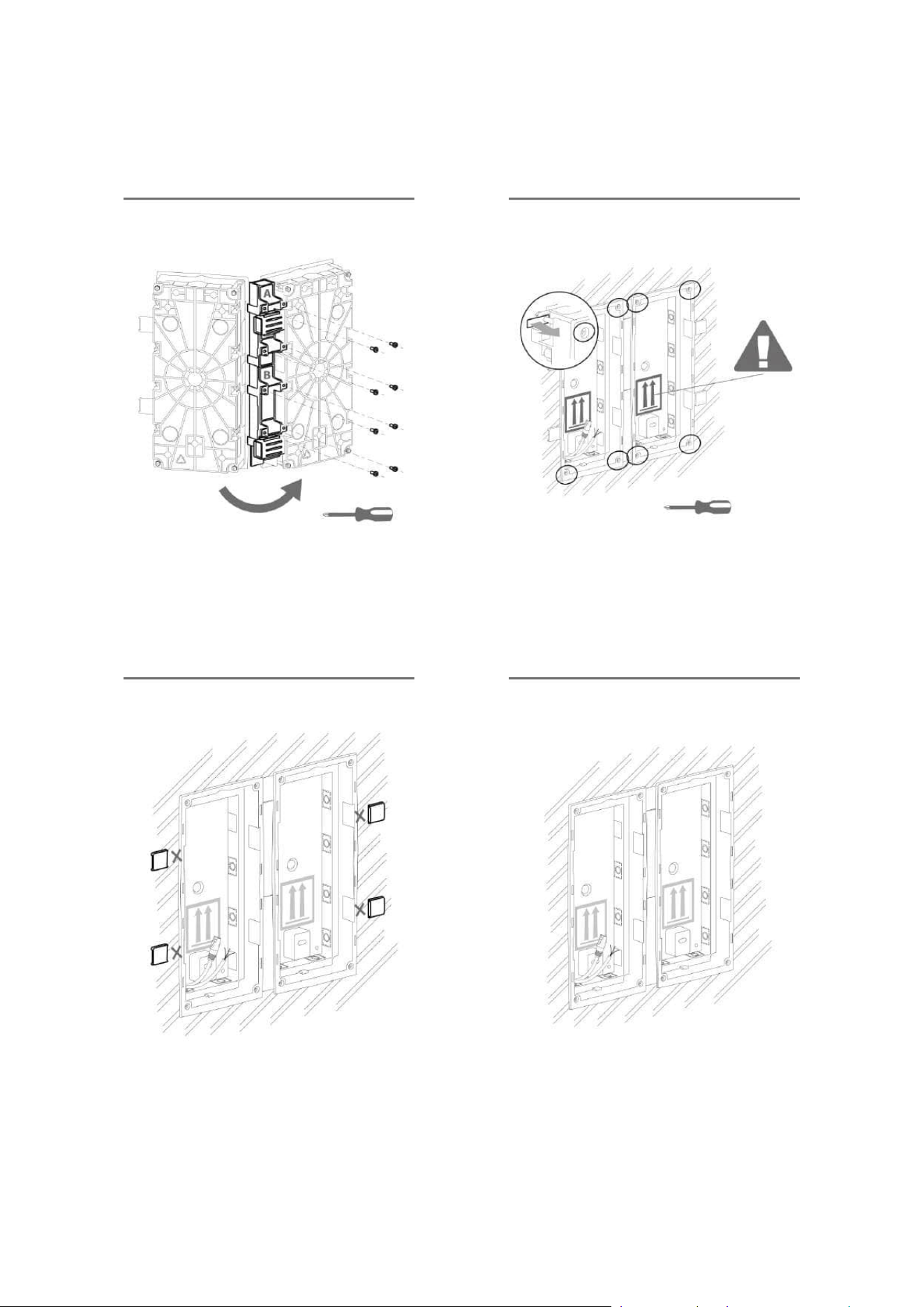
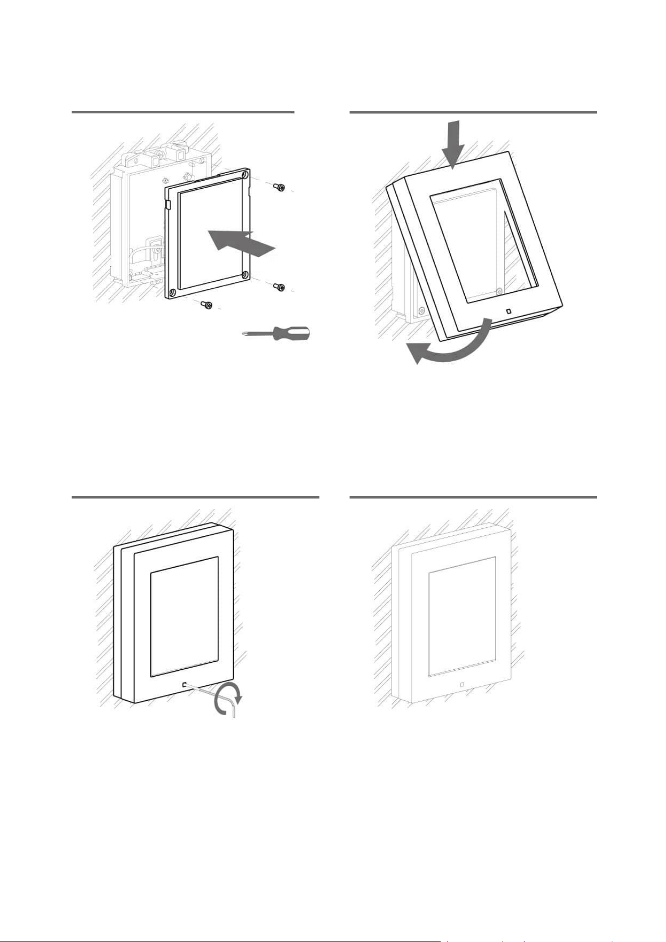
Warning!
The main unit may not be removed from its base, so do not remove the marked
resin-cast screw in the right-hand upper corner. Any screw tampering results in a
loss of warranty.
Make sure that the grounding element in the left-hand upper corner of the unit
remains undamaged and still stuck.

Installation manual 2N® IP Verso 2.0
71 / 213
•
•
•
•
•
•
•
•
•
•
•
•
•
1 module: box Part No. 9155014, frame Part No. 9155011
2 modules: box Part No. 9155015, frame Part No. 9155012
3 modules: box Part No. 9155016, frame Part No. 9155013
Flush mounting – plasterboard
What you need for mounting:
a properly cut hole as instructed in the box package
2N
®
IP Verso, flush mounting boxes and frames
1 module: box Part No. 9155014, frame Part No. 9155011
2 modules: box Part No. 9155015, frame Part No. 9155012
3 modules: box Part No. 9155016, frame Part No. 9155013
Module Installation
2.2.1.1 One Module Box
2.2.1.2 Two Module Box
2.2.1.3 More Two Module Boxes
2.2.1.4 Three Module Box
2.2.1.5 More Three Module Boxes
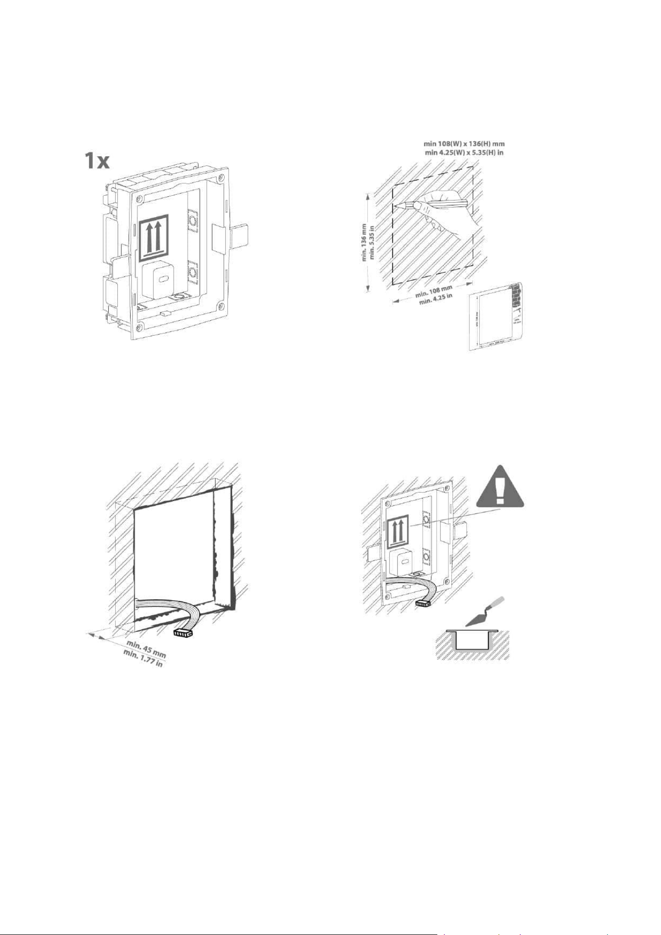
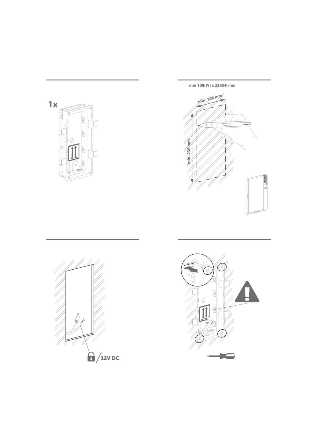
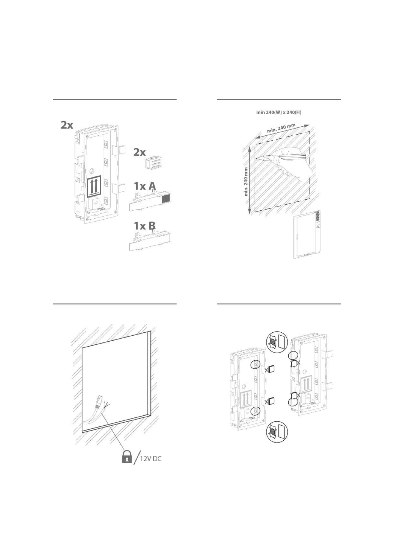
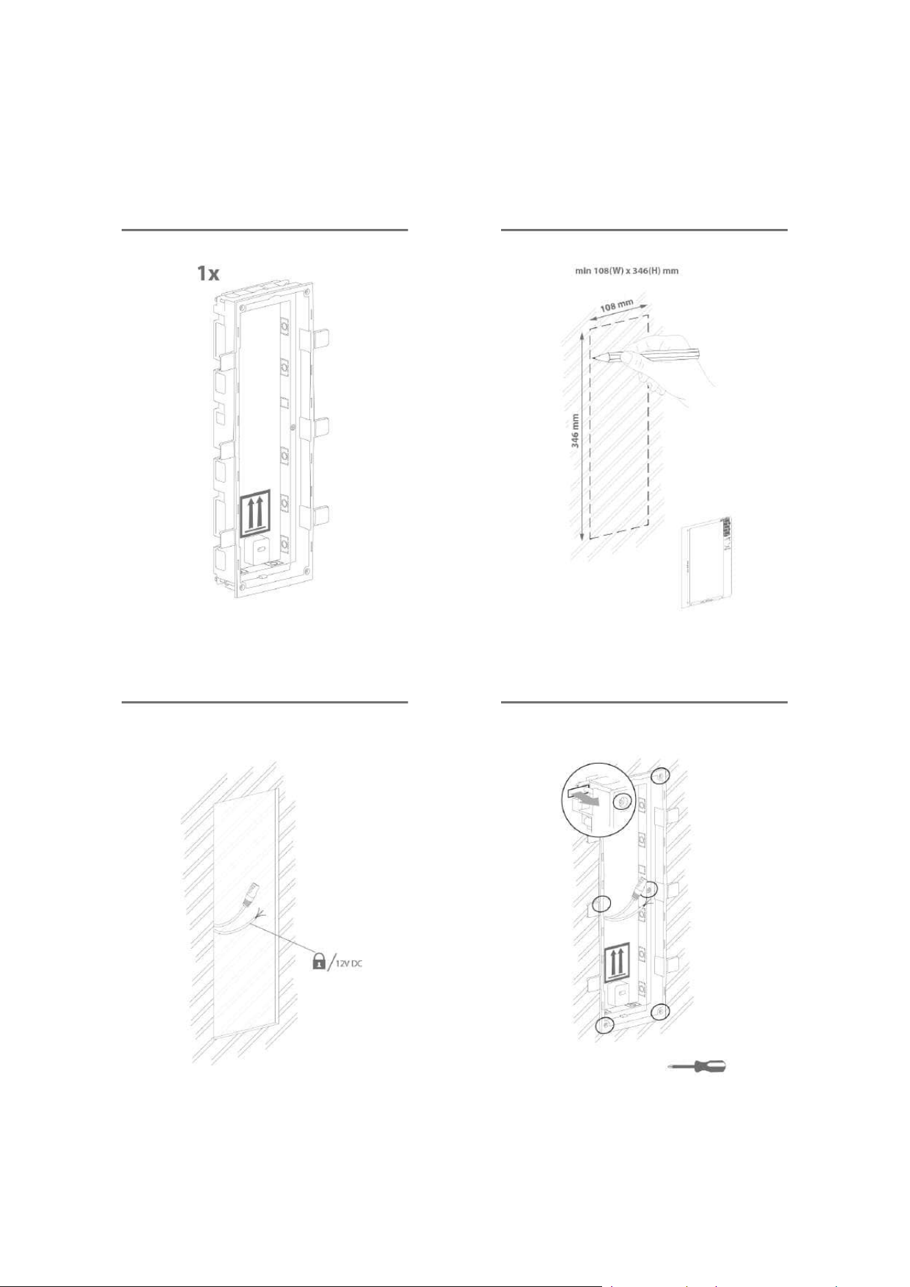
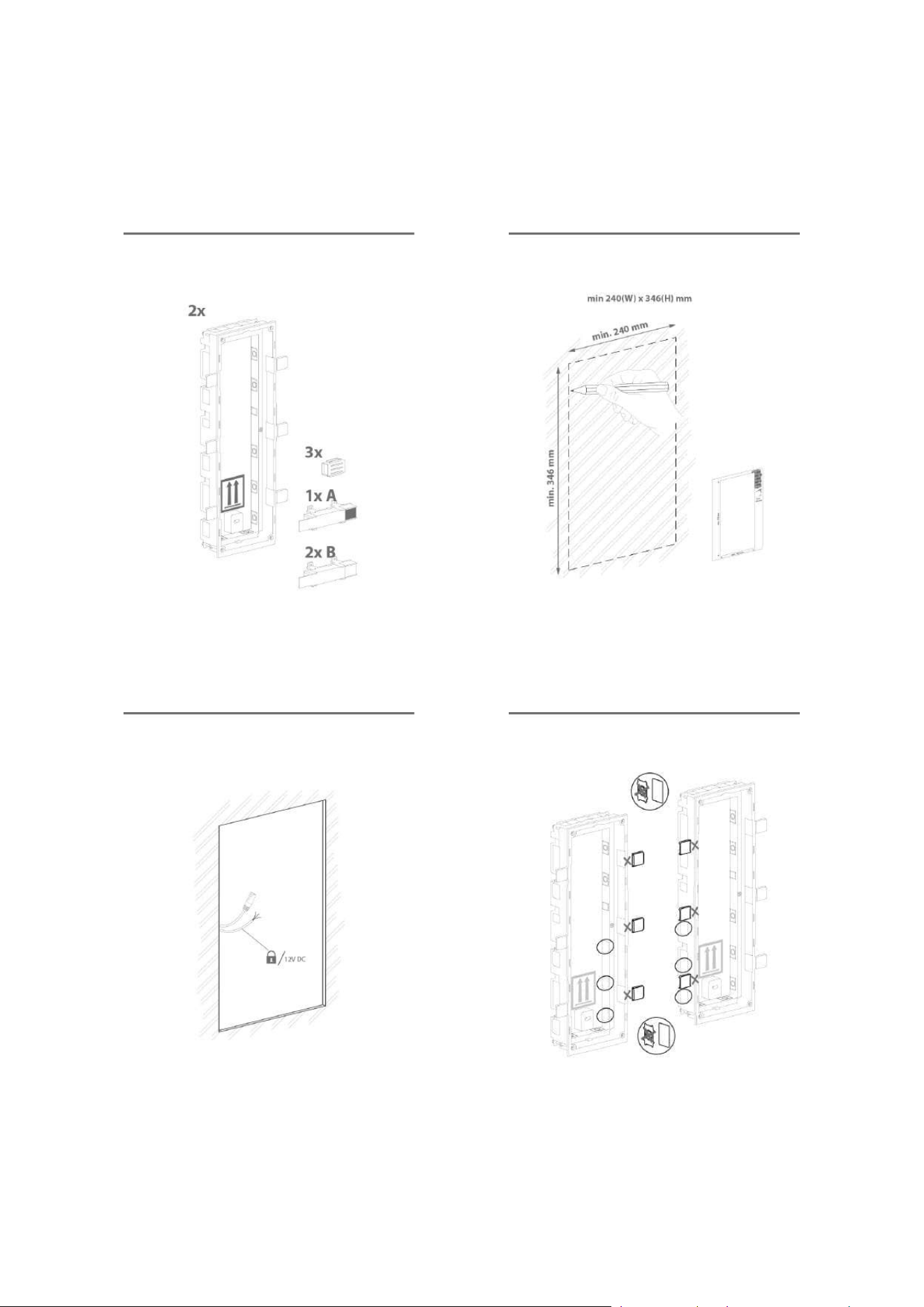
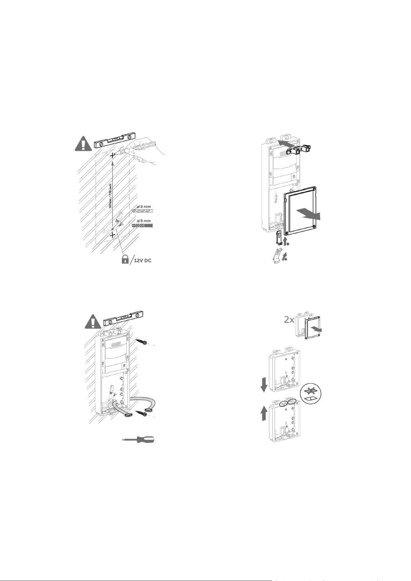
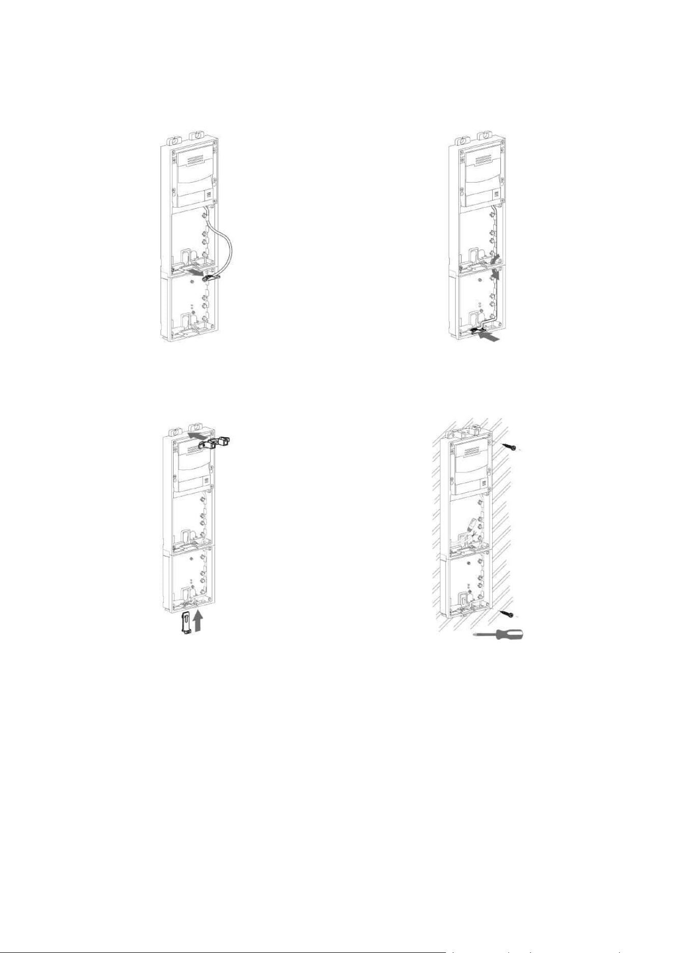
2.2.1.1 One Module Box
Flush mounting box mounting – classic bricks
Note
Multiple units can be combined in all mounting types.
•
Caution
The one-module box is designed for stand-alone installations of extending
modules such as departure readers. A two-module box is required for the main
unit installation.
Installation manual 2N® IP Verso 2.0
72 / 213
Installation manual 2N® IP Verso 2.0
73 / 213
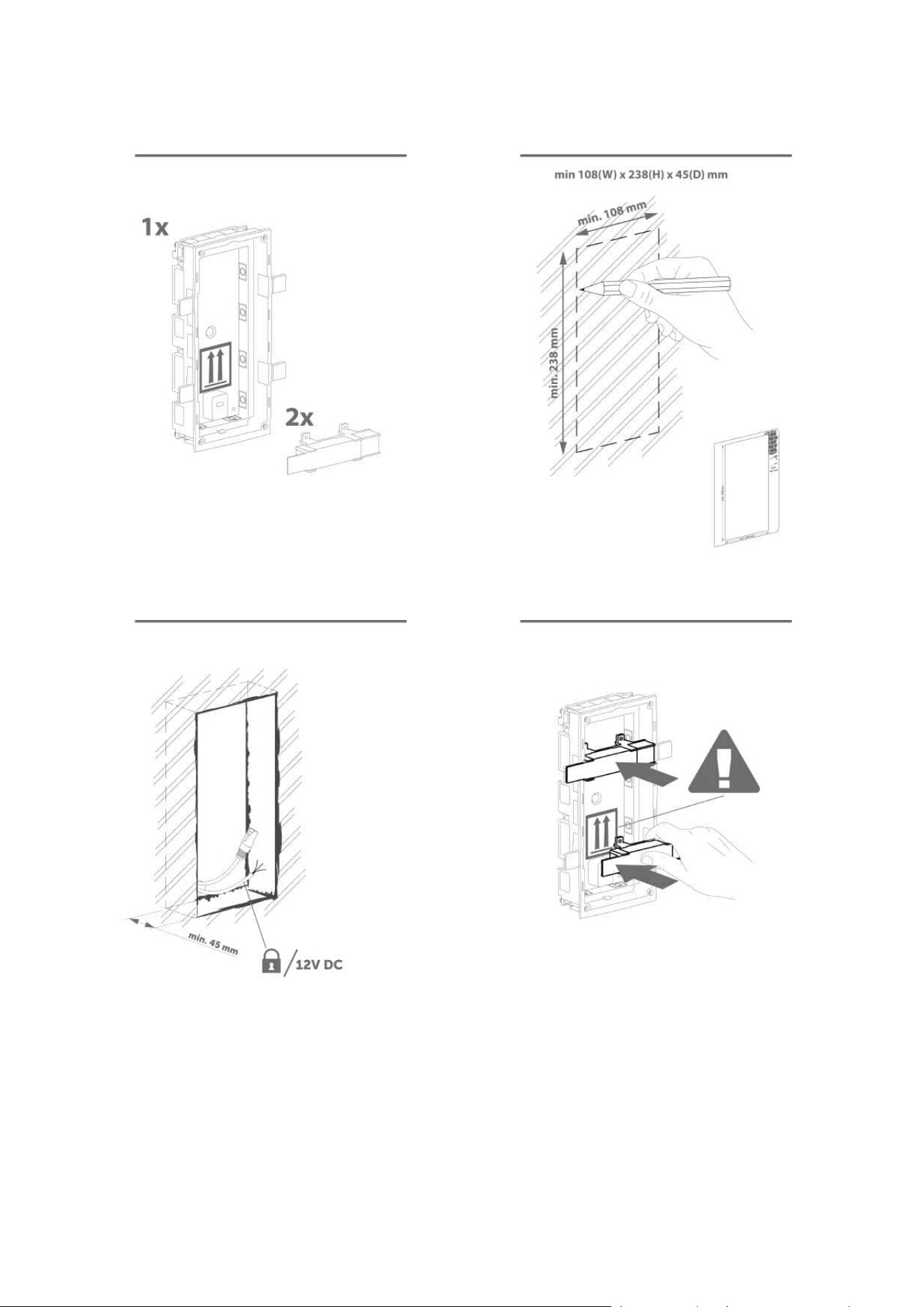
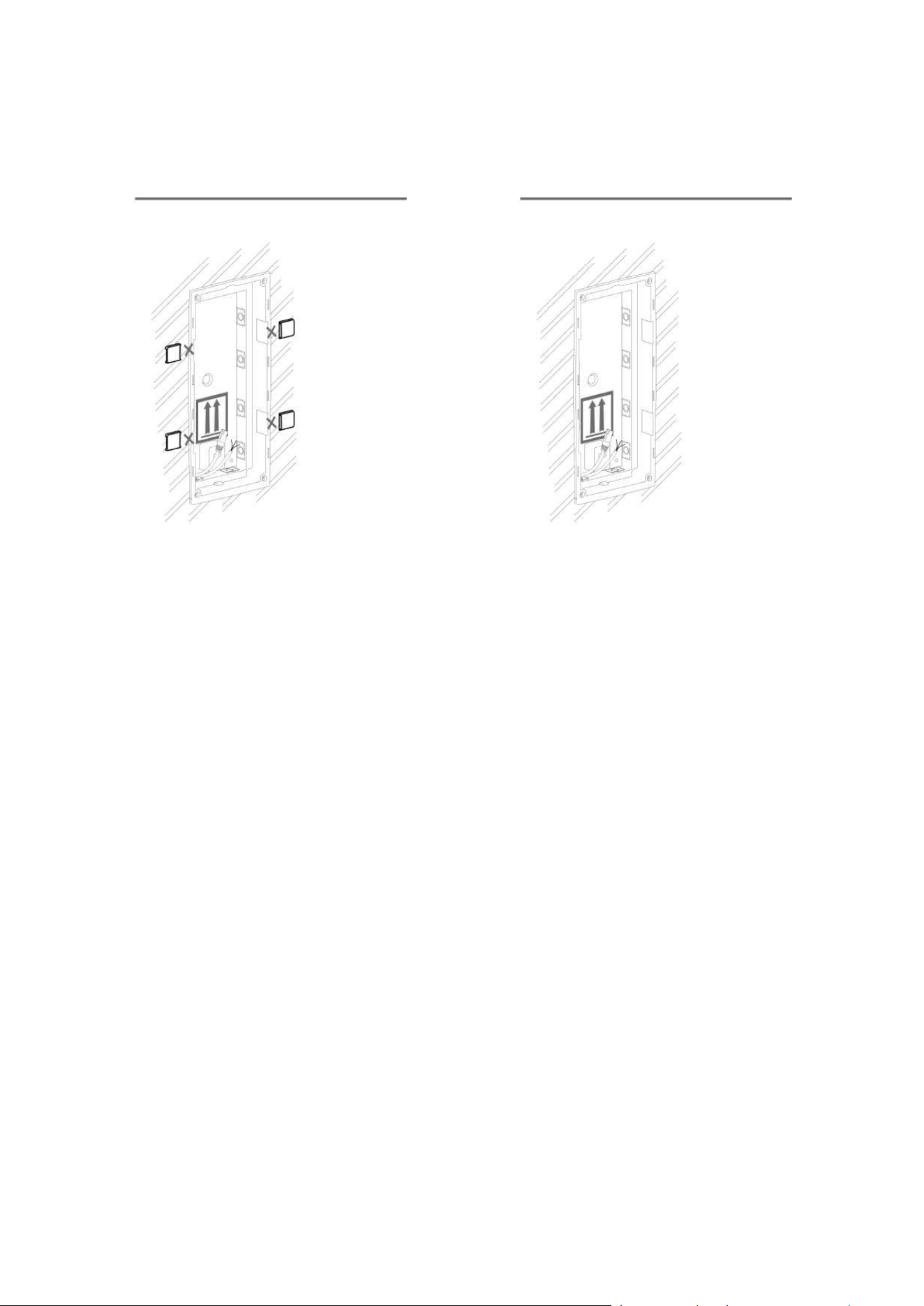
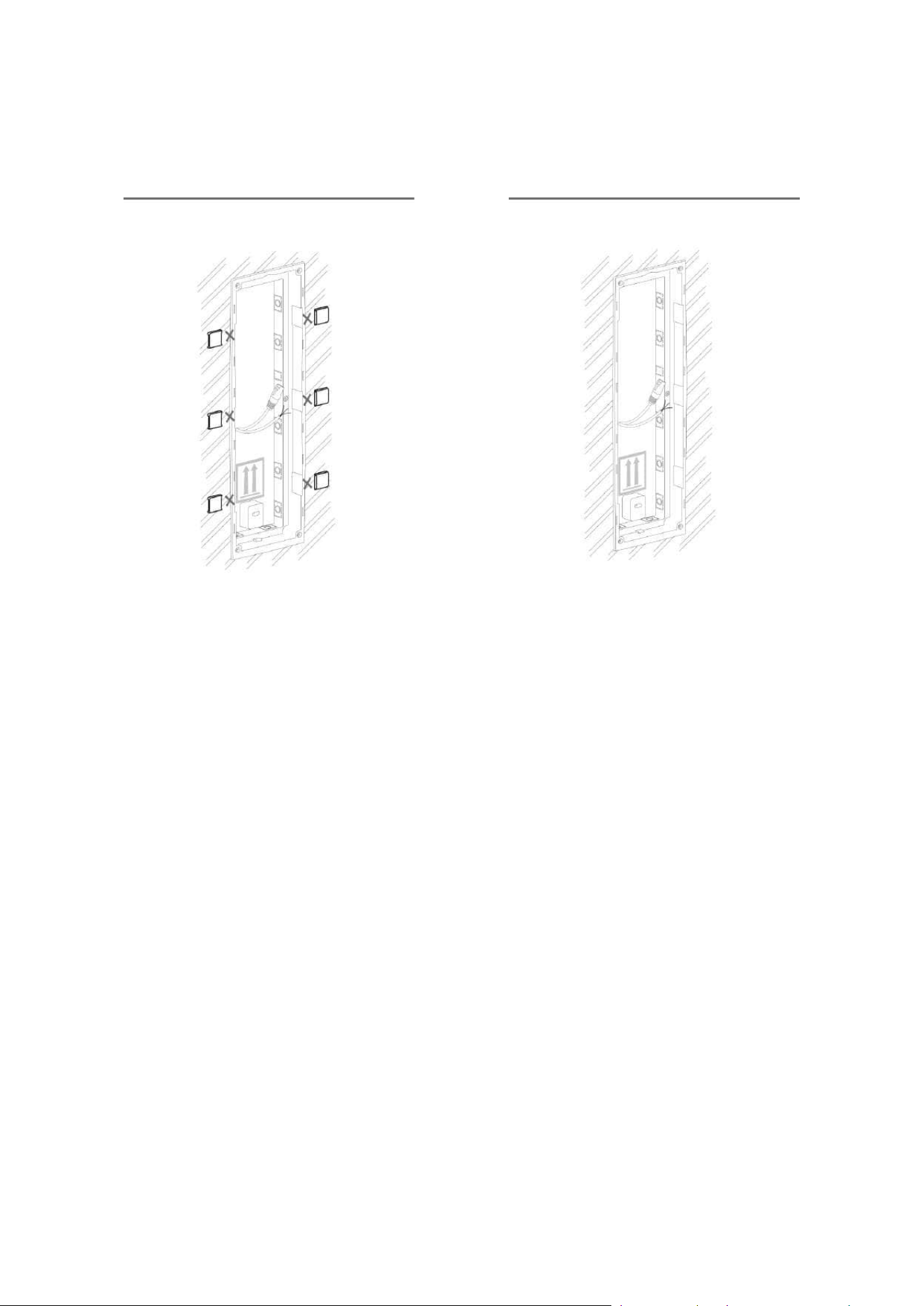
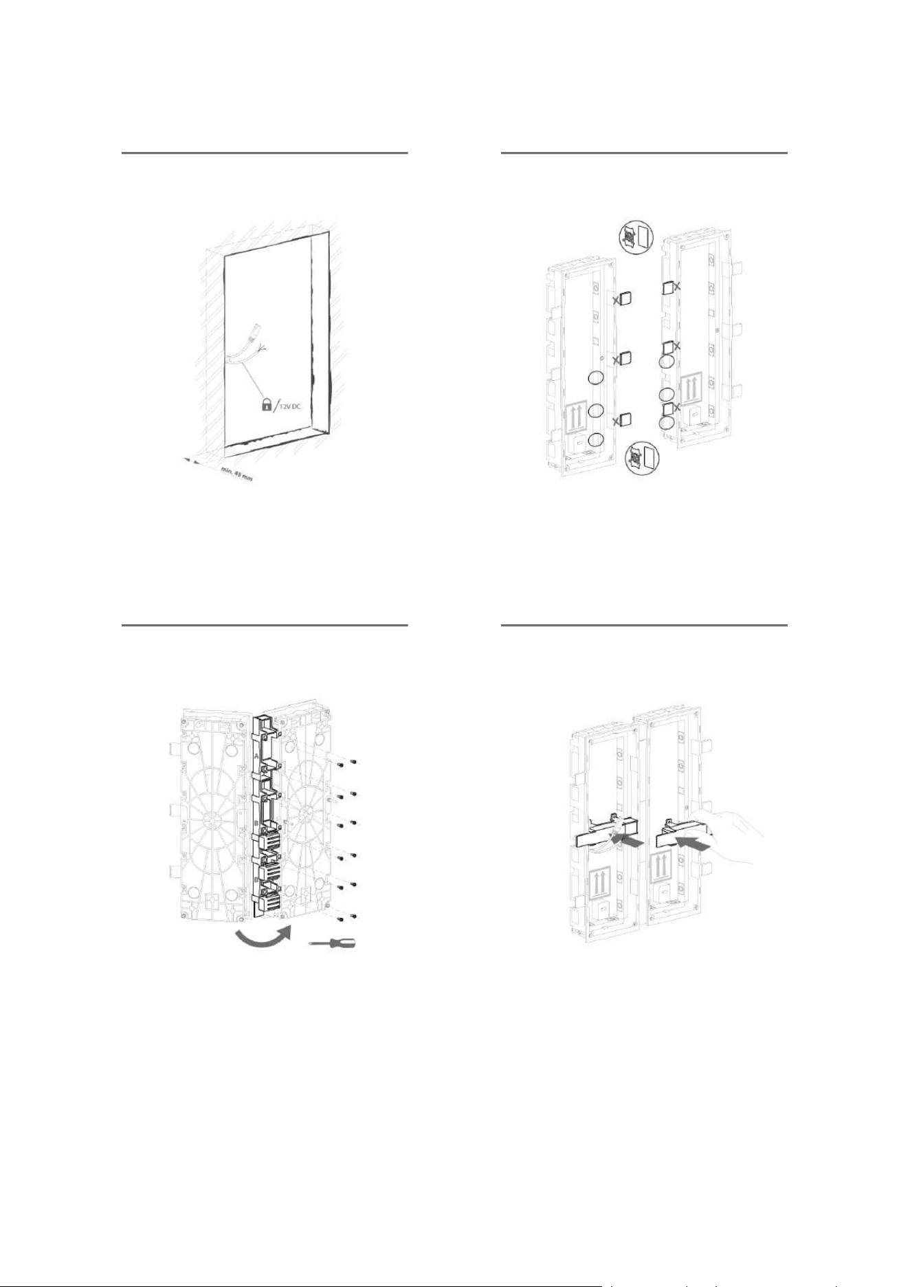
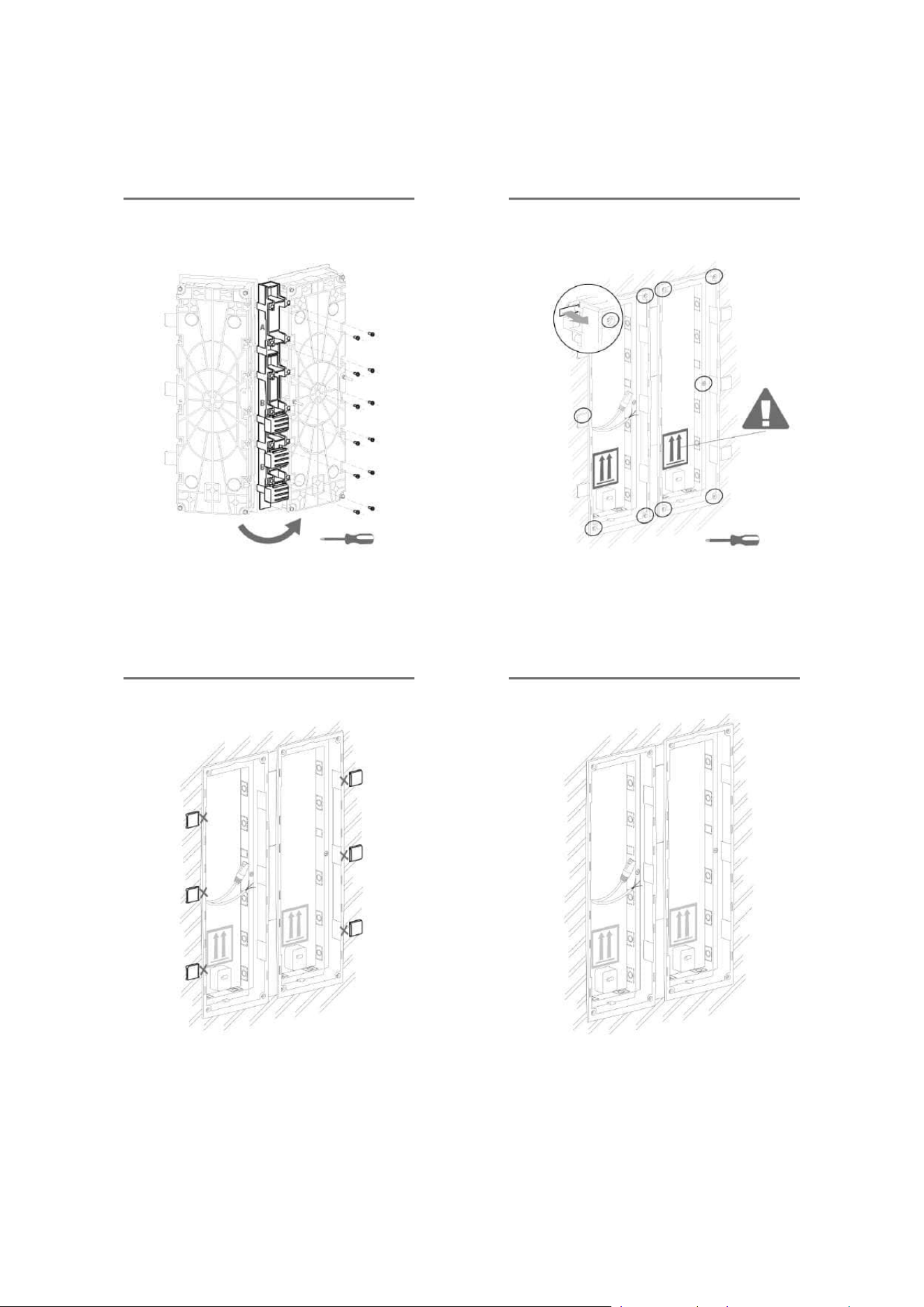
•
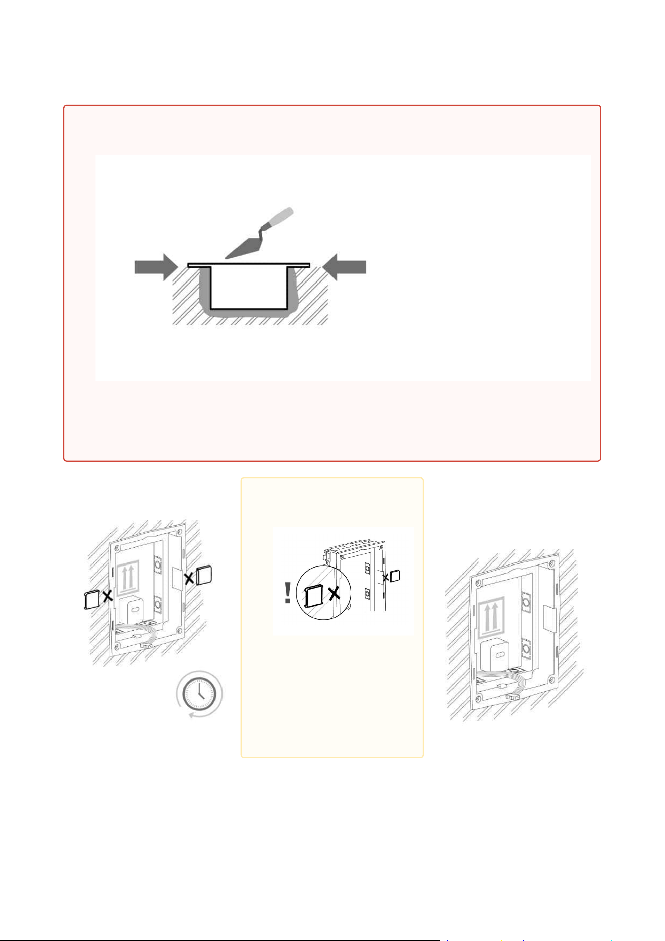
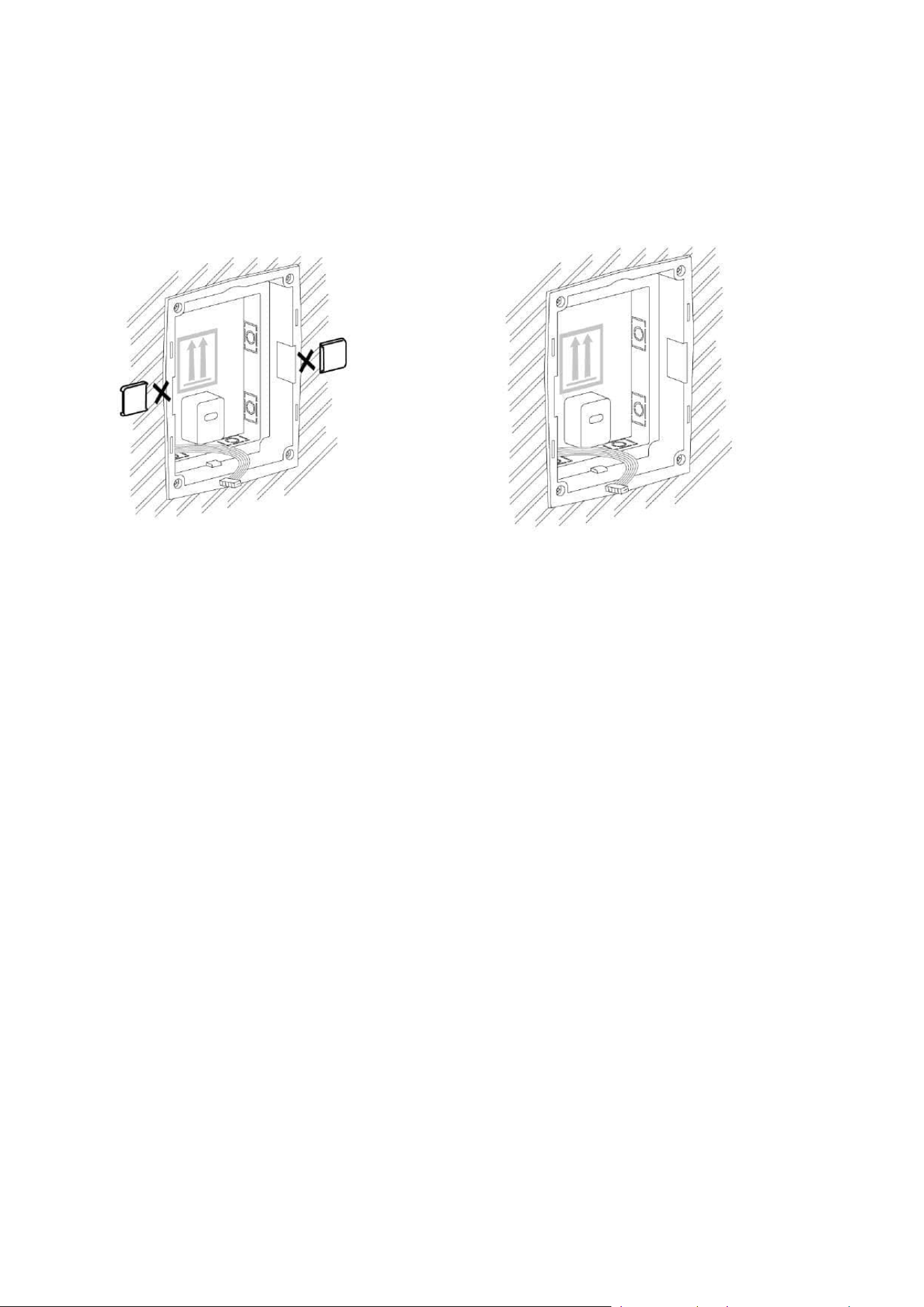
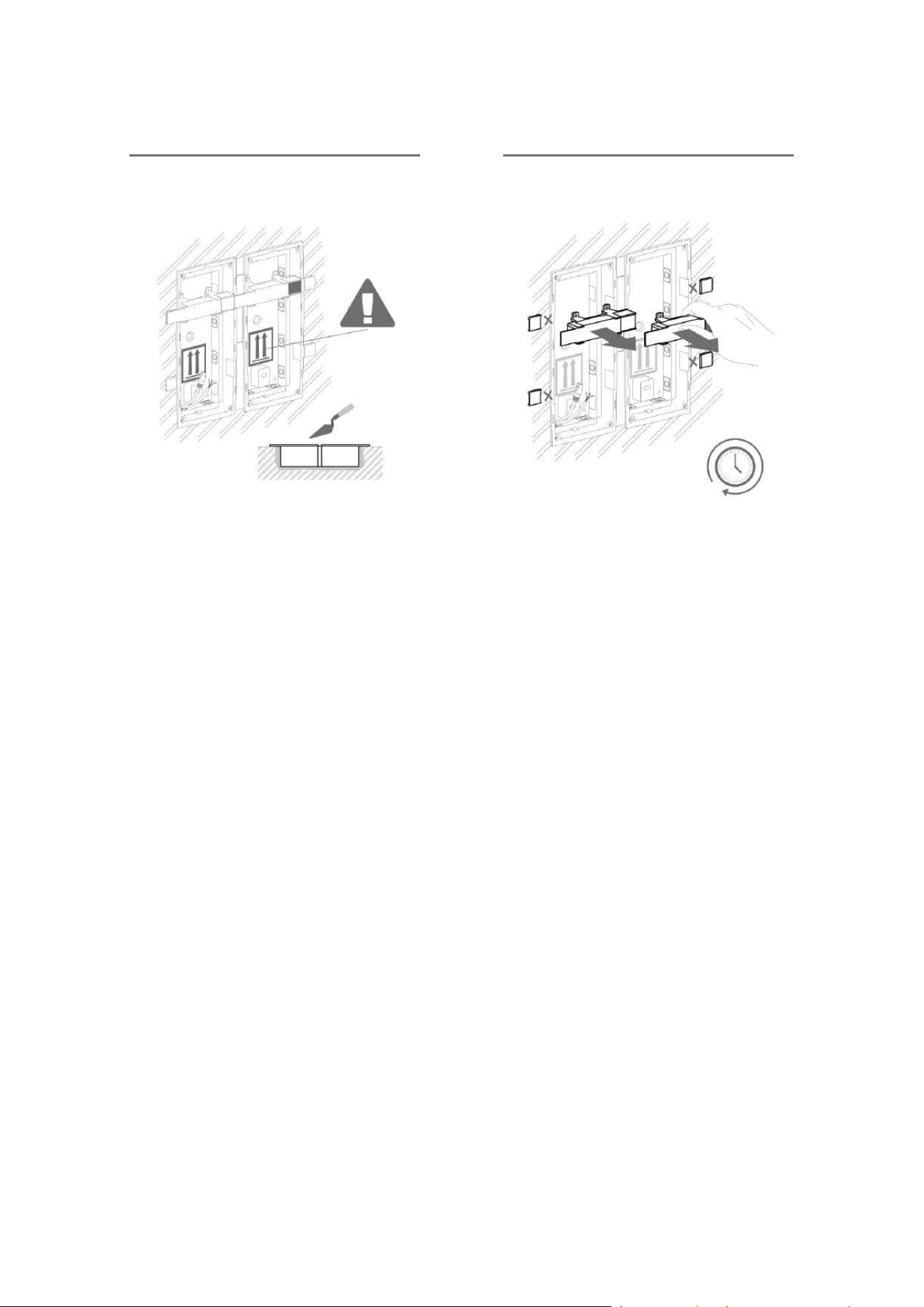
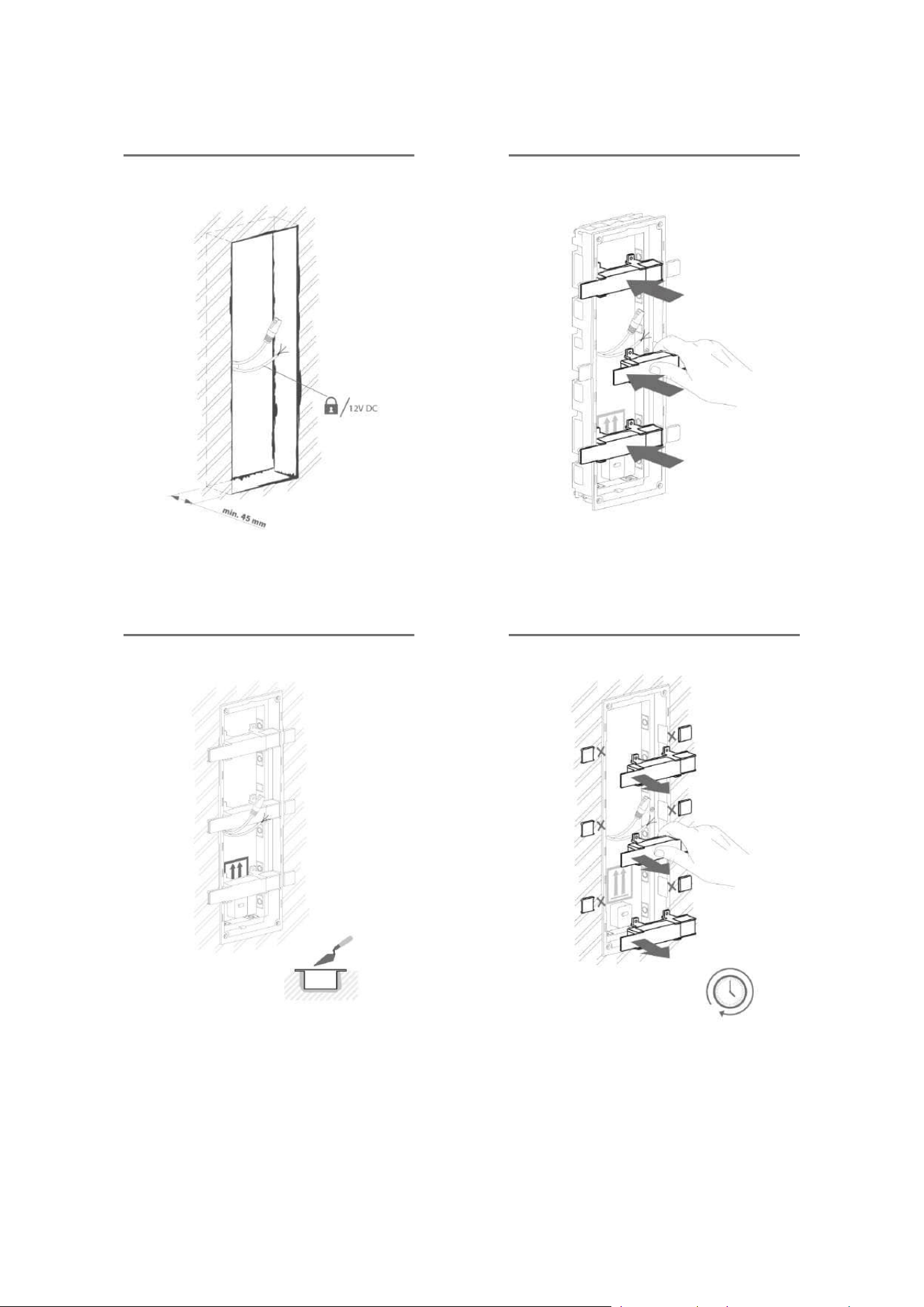
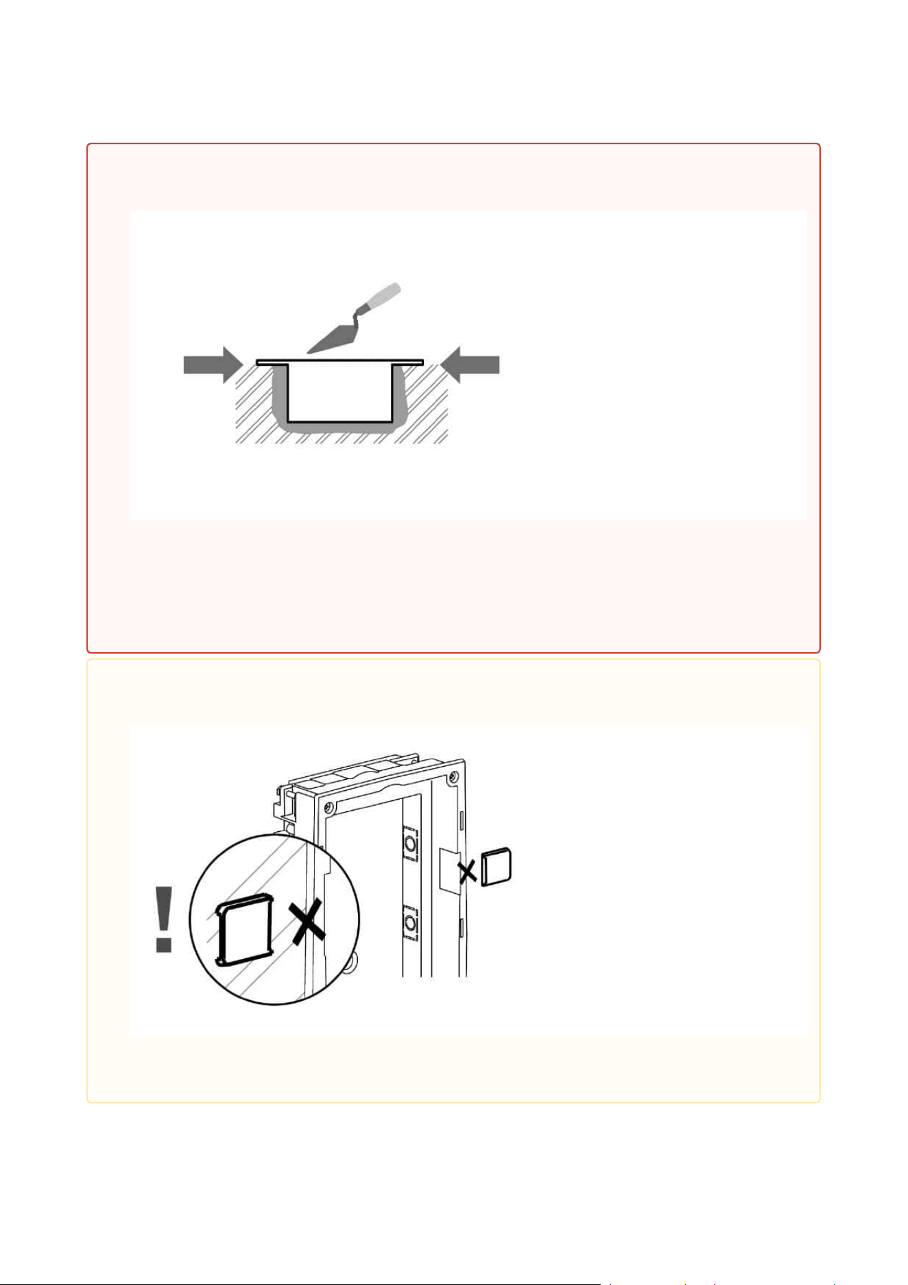
Warning!
Make sure that the flush mounting box is slightly above the wall surface not
aligning with the wall. A wrong installation may lead to water penetration and
subsequent damage of the device. Use the side protrusions to achieve the proper
flush mounting.
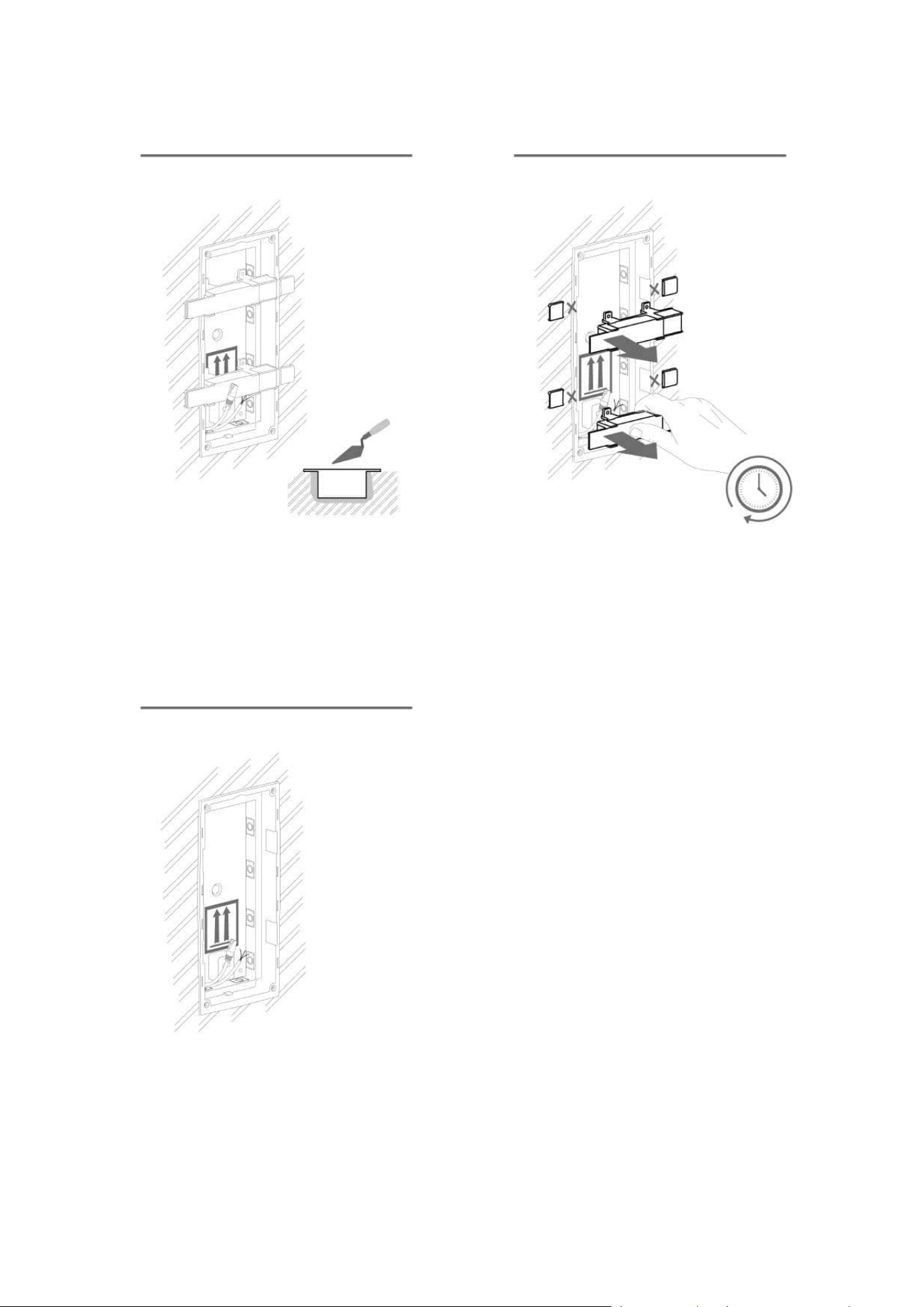
•
Caution
Break off the side
protrusions when
the walling
material has
hardened.
Installation manual 2N® IP Verso 2.0
74 / 213
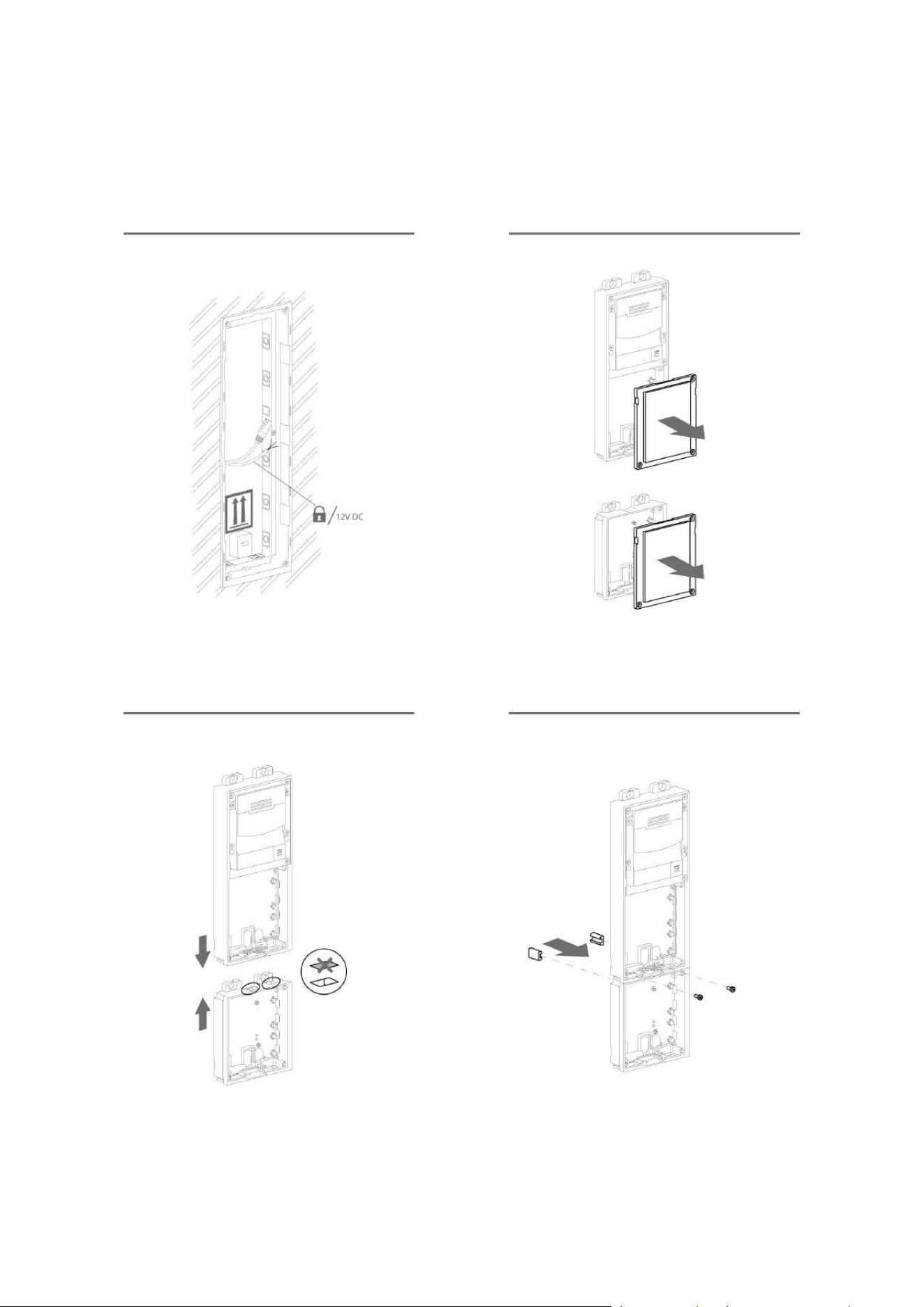
Flush mounting box mounting – plasterboard
Installation manual 2N® IP Verso 2.0
75 / 213
Installation manual 2N® IP Verso 2.0
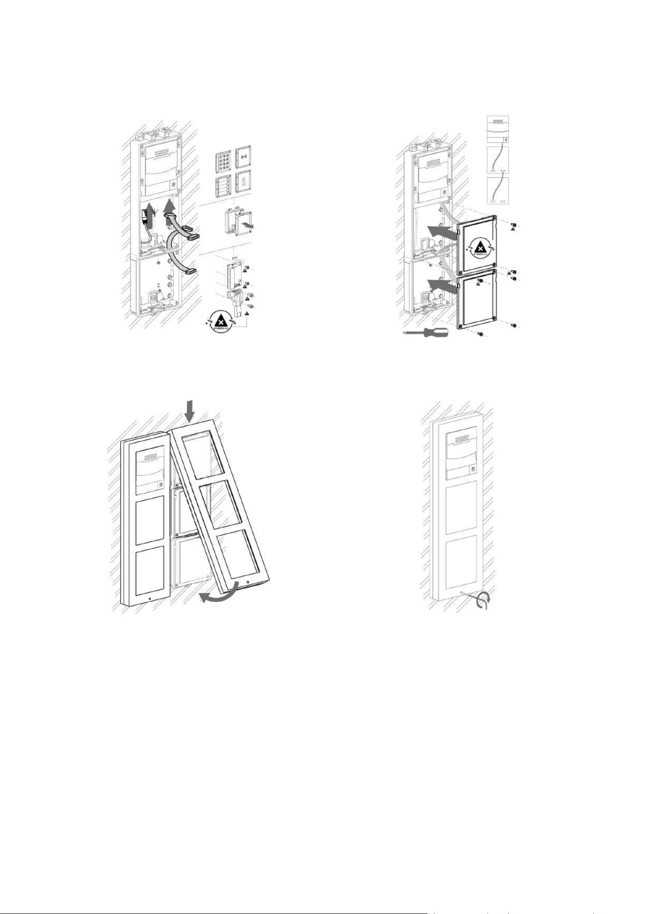
76 / 213
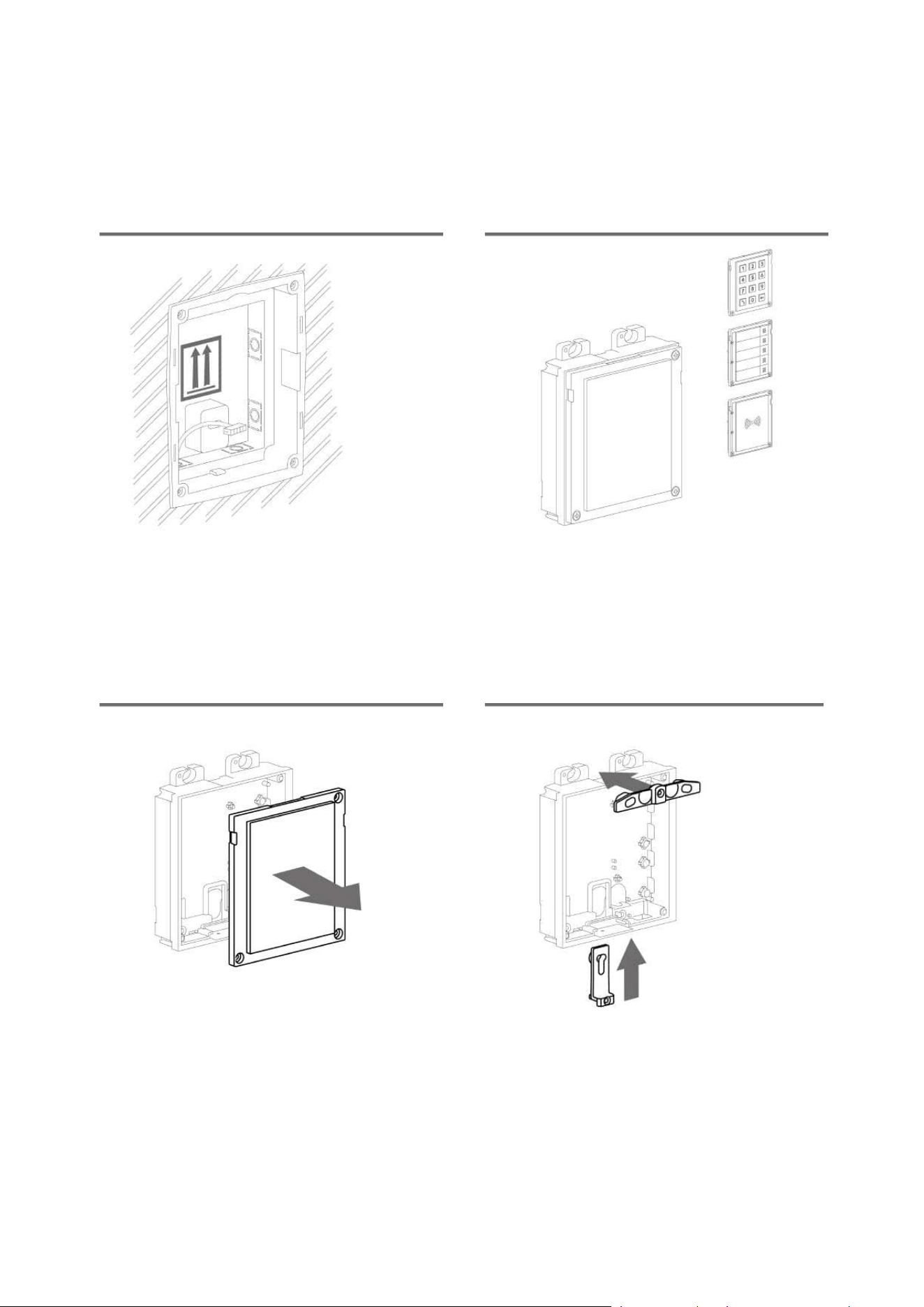
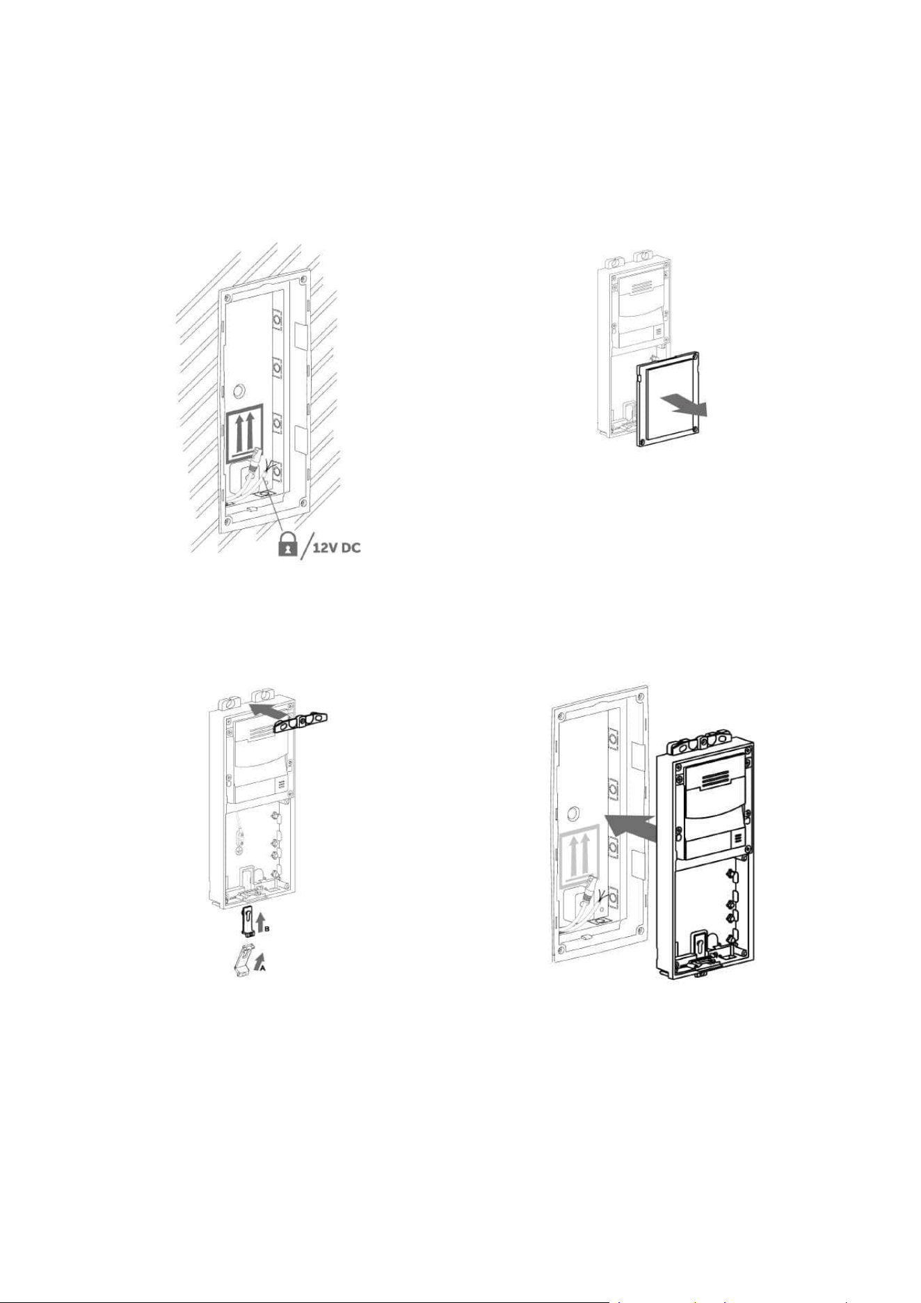
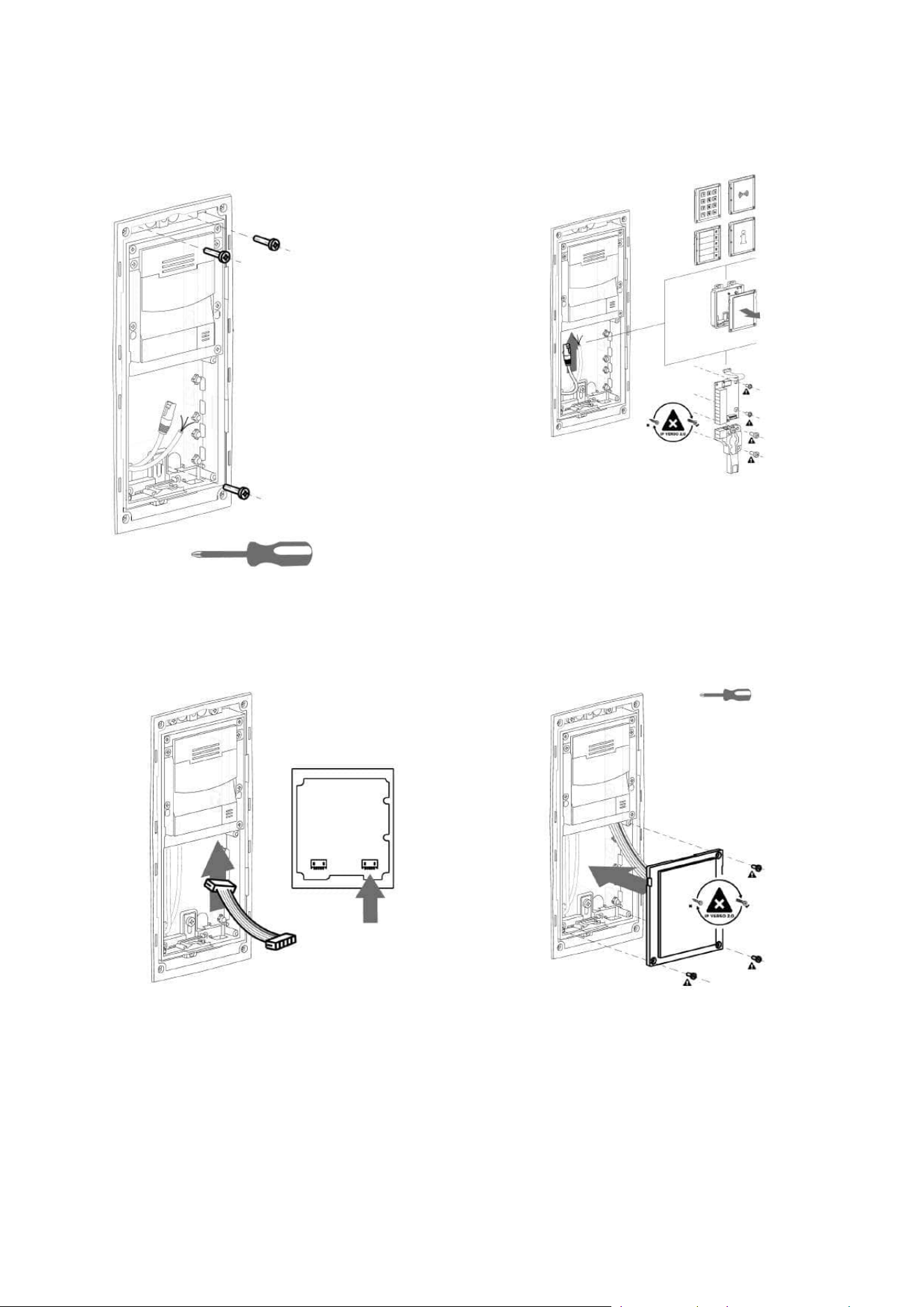
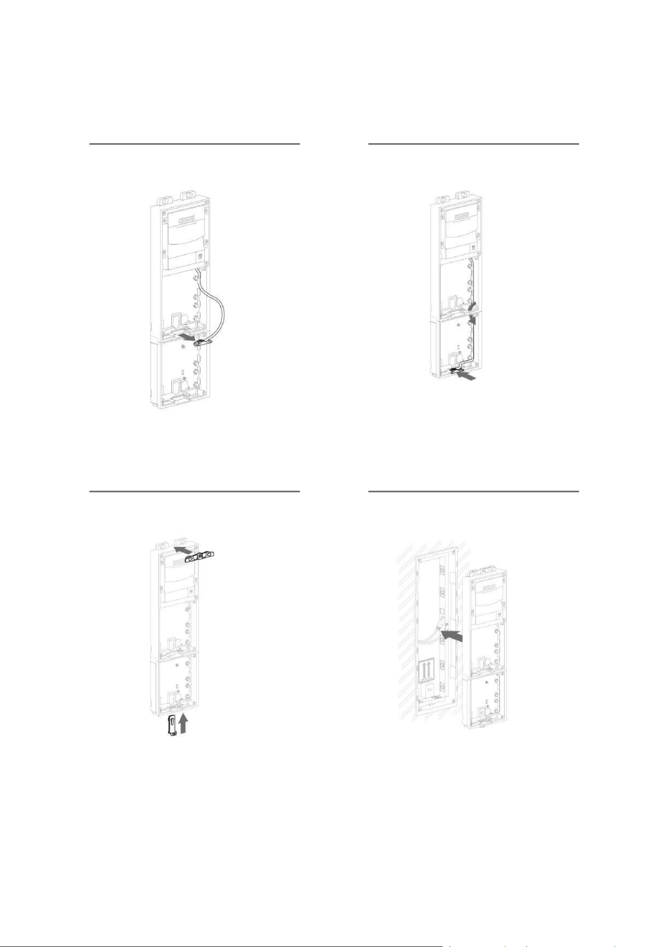
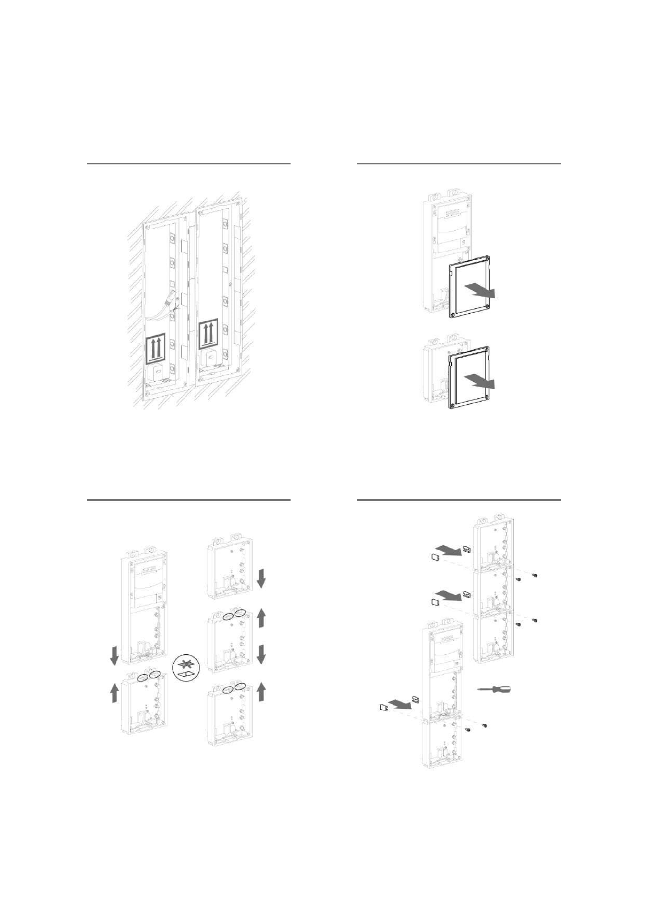
Flush module mounting
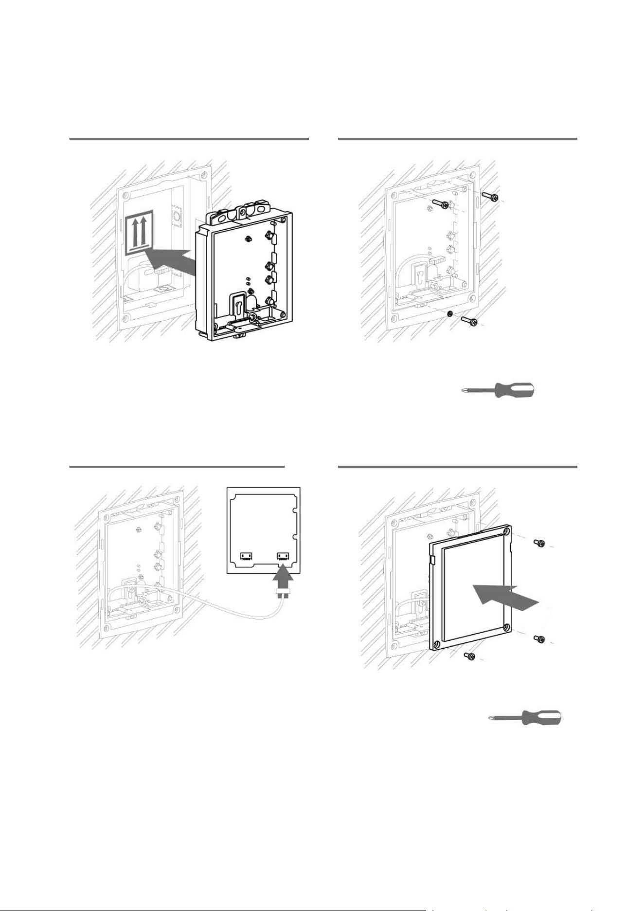
Installation manual 2N® IP Verso 2.0
77 / 213
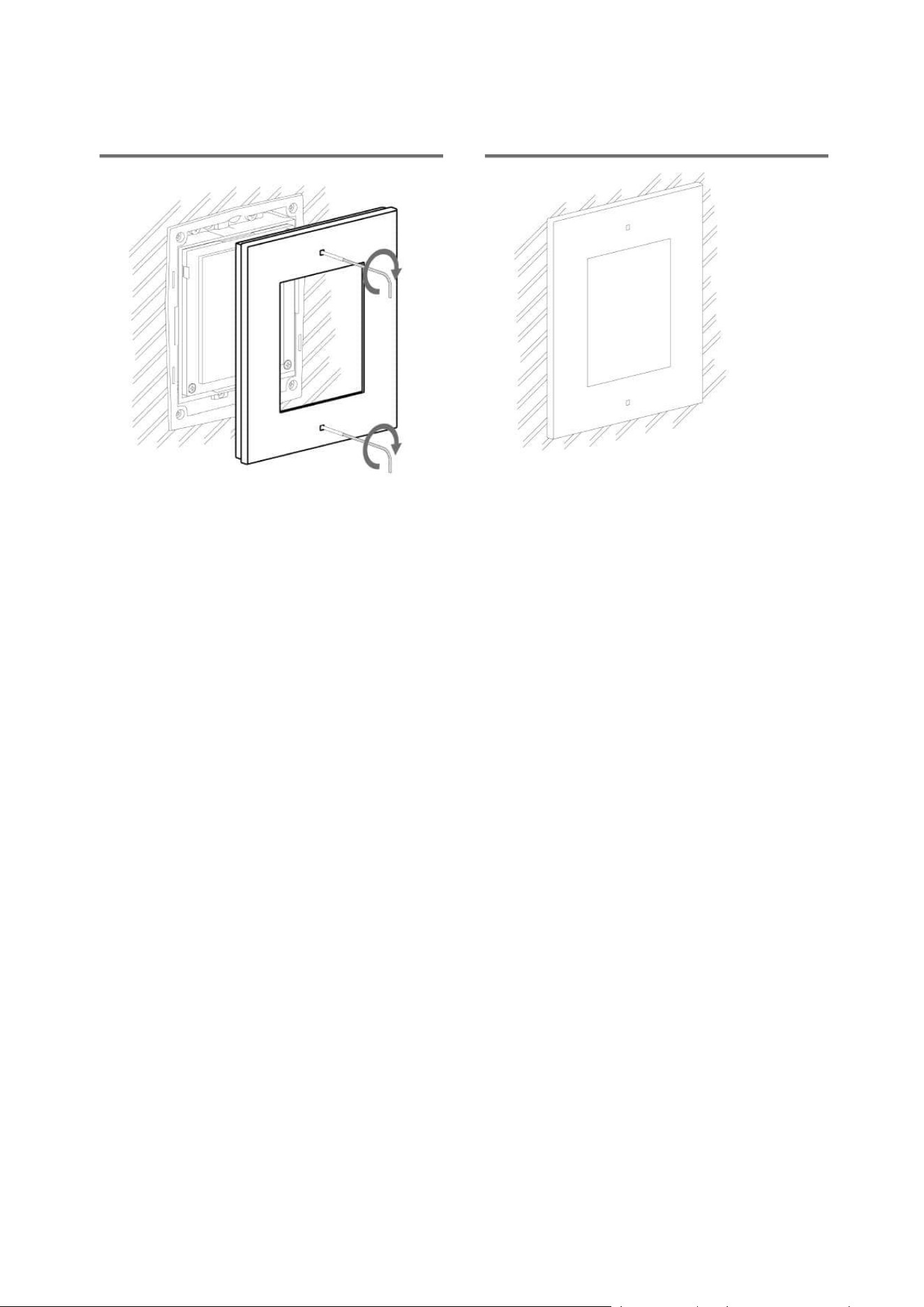
Installation manual 2N® IP Verso 2.0
78 / 213
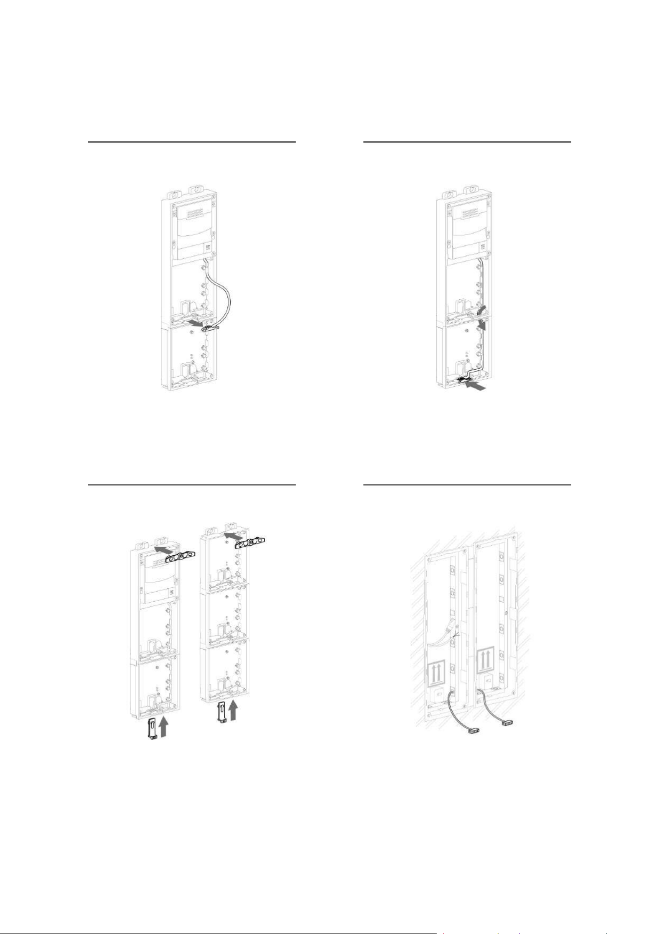
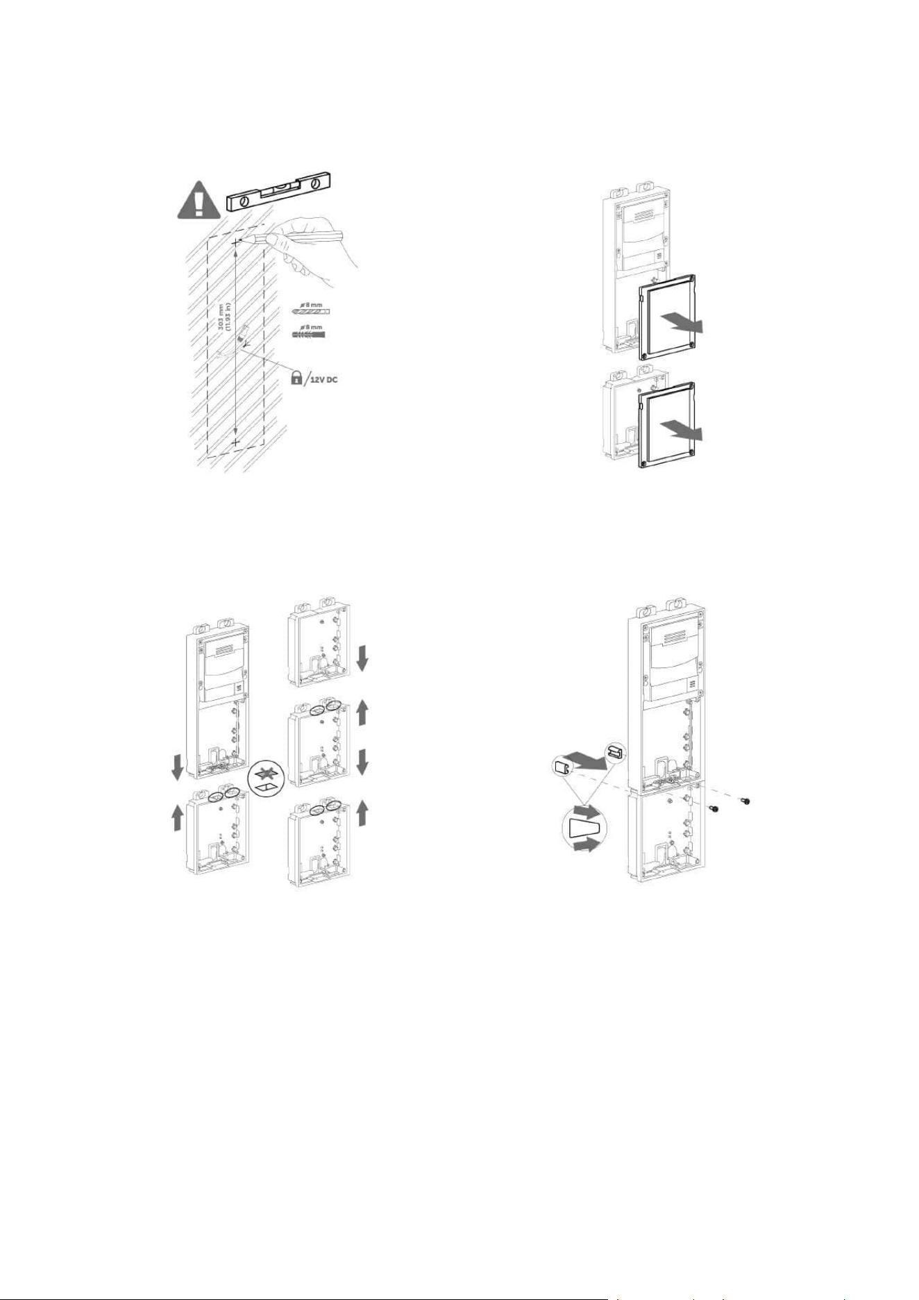
2.2.1.2 Two Module Box
Flush mounting box – classic bricks
Installation manual 2N® IP Verso 2.0
79 / 213
Installation manual 2N® IP Verso 2.0
80 / 213

Installation manual 2N® IP Verso 2.0
81 / 213
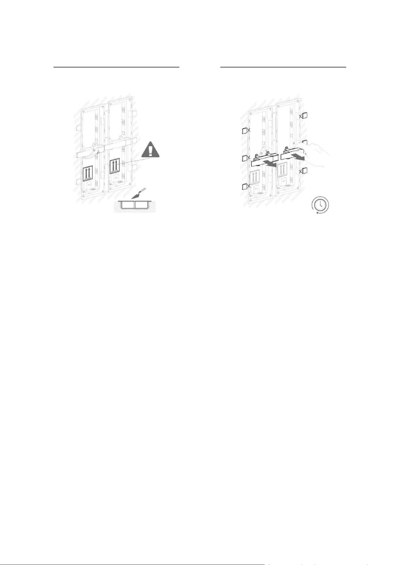
•
Warning!
Make sure that the flush mounting box is slightly above the wall surface not
aligning with the wall. A wrong installation may lead to water penetration and
subsequent damage of the device. Use the side protrusions to achieve the proper
flush mounting.
•
Caution
Break off the side protrusions when the walling material has hardened.
Installation manual 2N® IP Verso 2.0
82 / 213
Flush mounting box – plasterboard
Installation manual 2N® IP Verso 2.0
83 / 213
Installation manual 2N® IP Verso 2.0
84 / 213
Flush module mounting
Installation manual 2N® IP Verso 2.0
85 / 213
Installation manual 2N® IP Verso 2.0
86 / 213
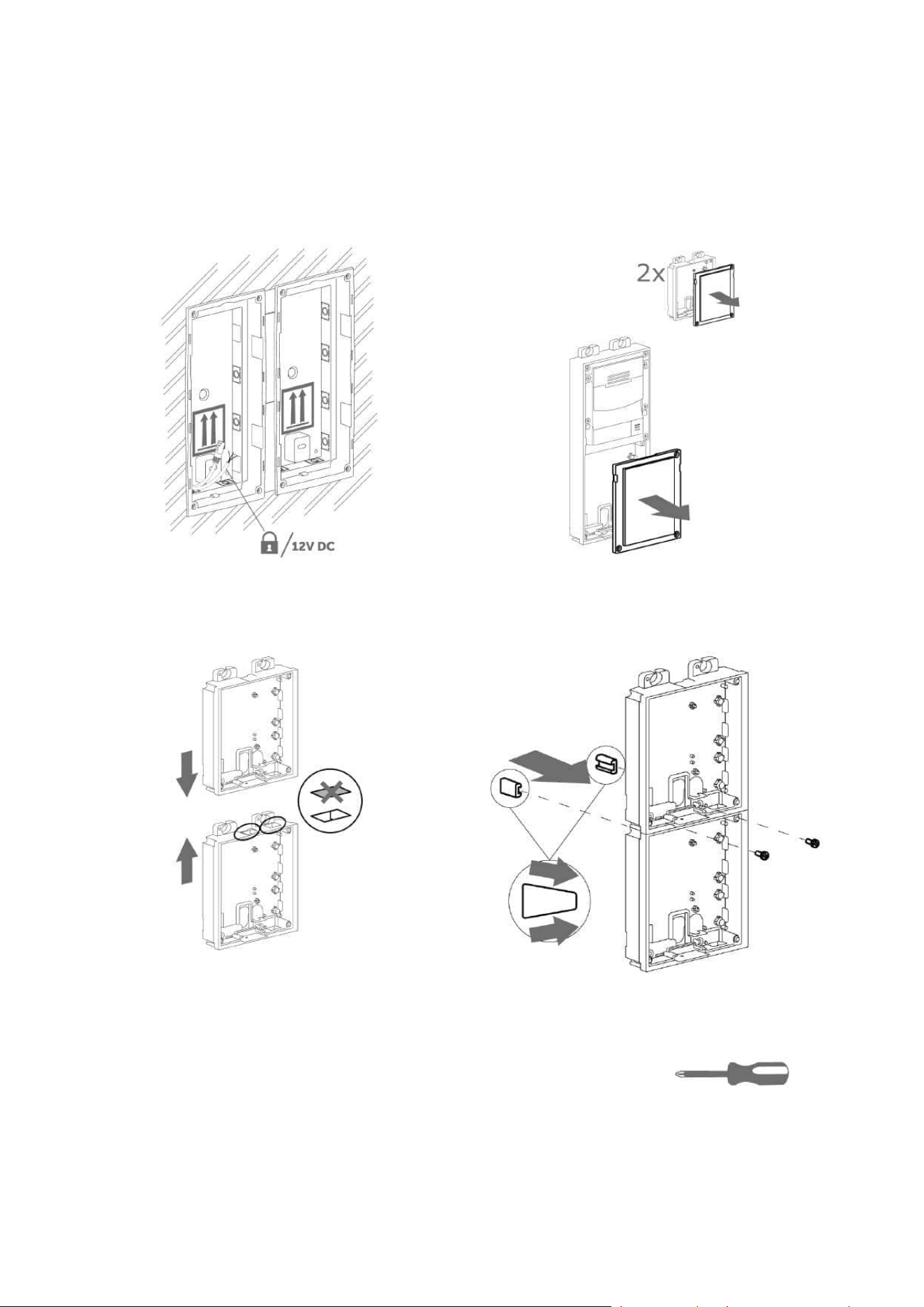
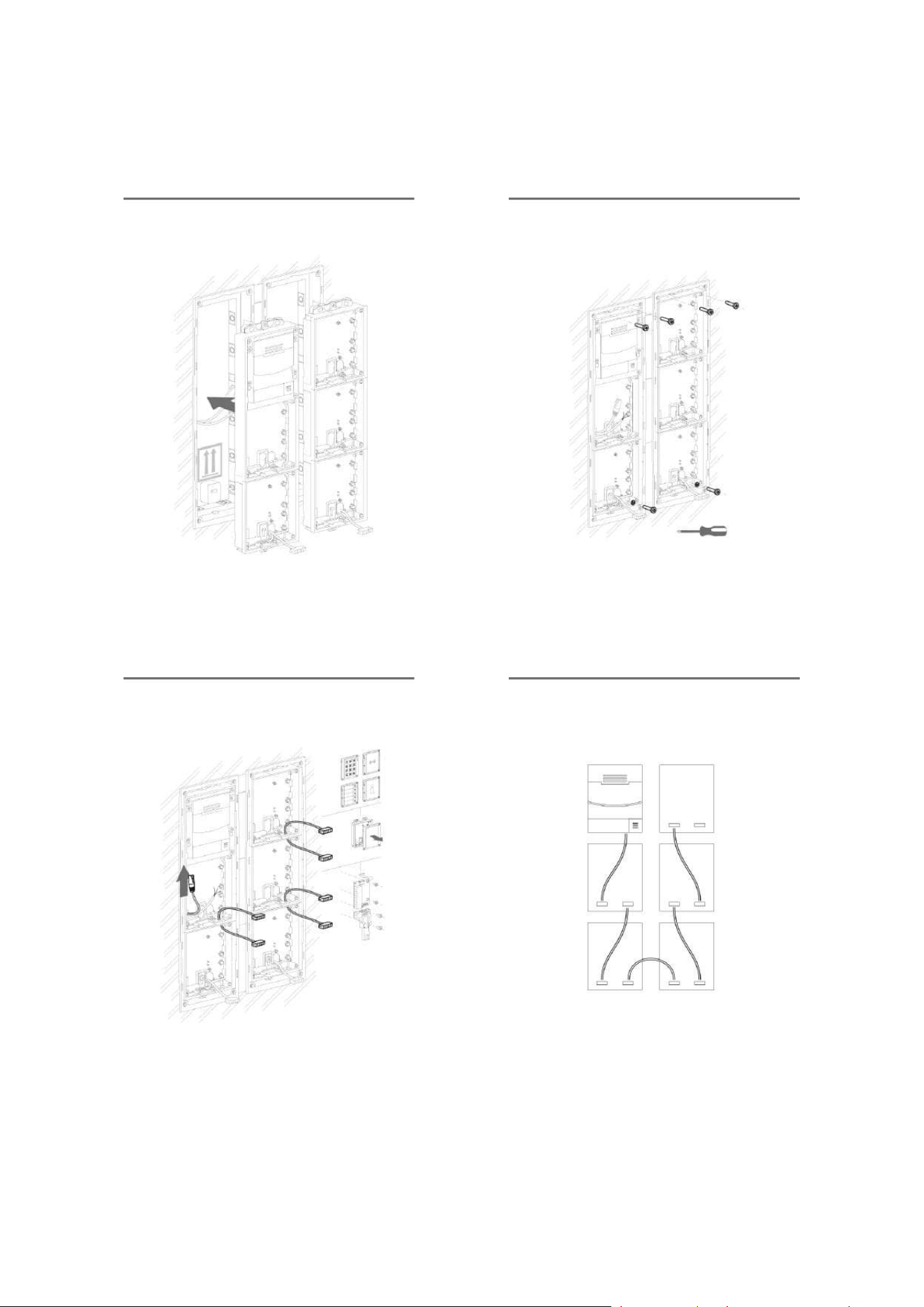
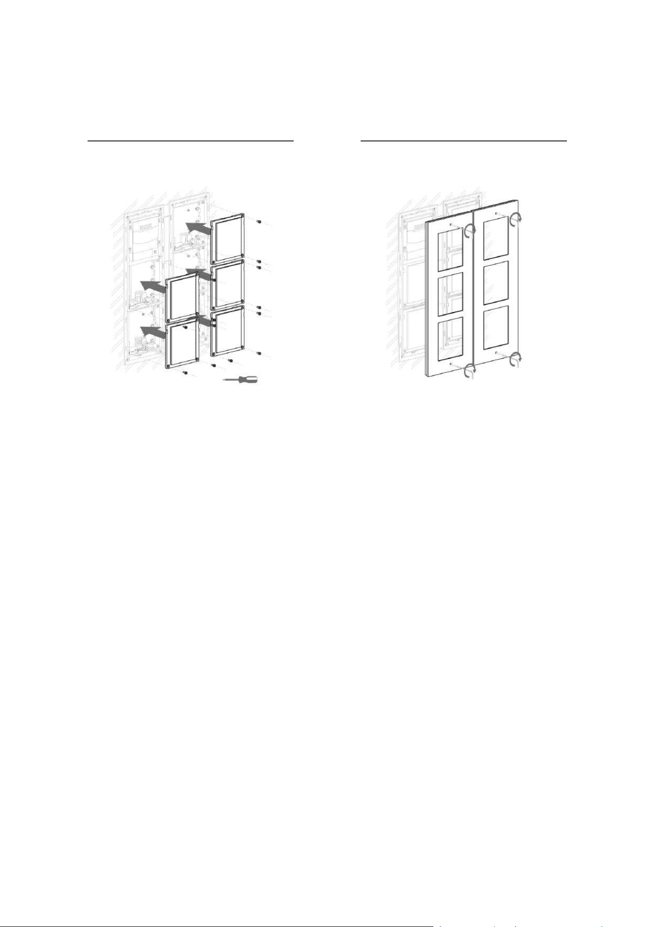
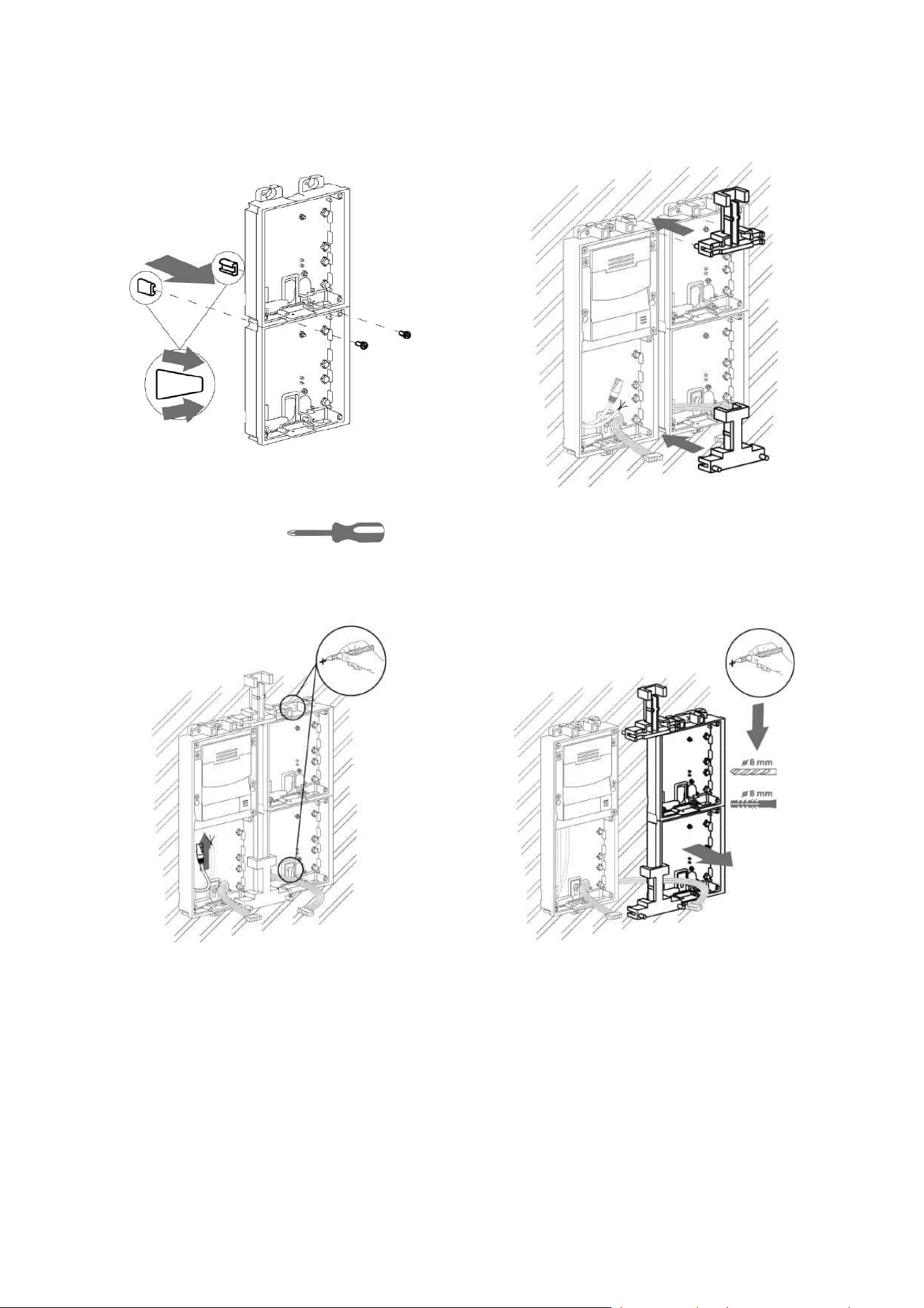
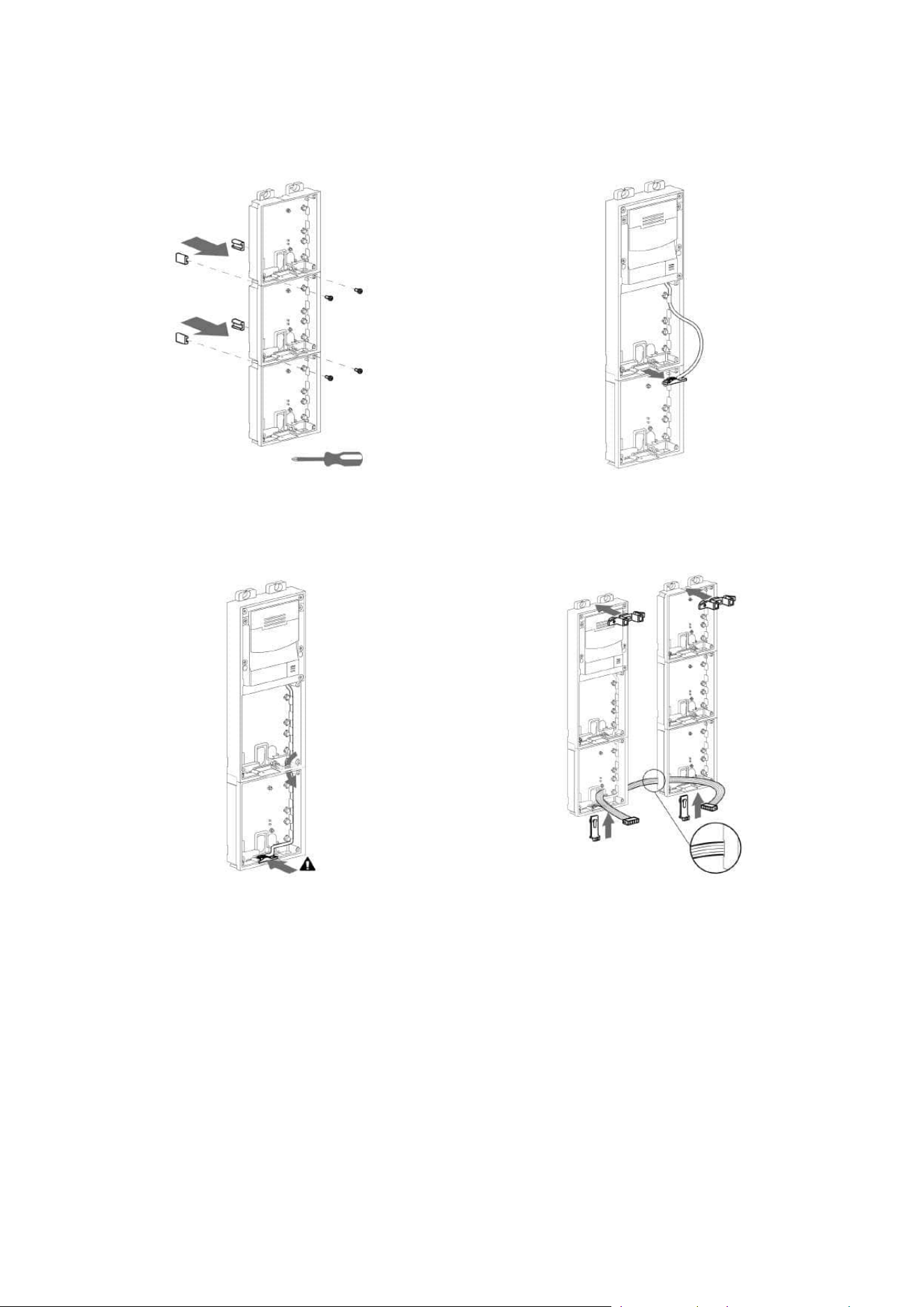
2.2.1.3 More Two Module Boxes
Flush mounting box – classic bricks
Installation manual 2N® IP Verso 2.0
87 / 213
Installation manual 2N® IP Verso 2.0
88 / 213
Installation manual 2N® IP Verso 2.0
89 / 213
•
Warning!
Make sure that the flush mounting box is slightly above the wall surface not
aligning with the wall. A wrong installation may lead to water penetration and
subsequent damage of the device. Use the side protrusions to achieve the proper
flush mounting.
•
Caution
Break off the side protrusions when the walling material has hardened.

Installation manual 2N® IP Verso 2.0
90 / 213
Installation manual 2N® IP Verso 2.0
91 / 213
Flush mounting box – plasterboard
Installation manual 2N® IP Verso 2.0
92 / 213
Installation manual 2N® IP Verso 2.0
93 / 213
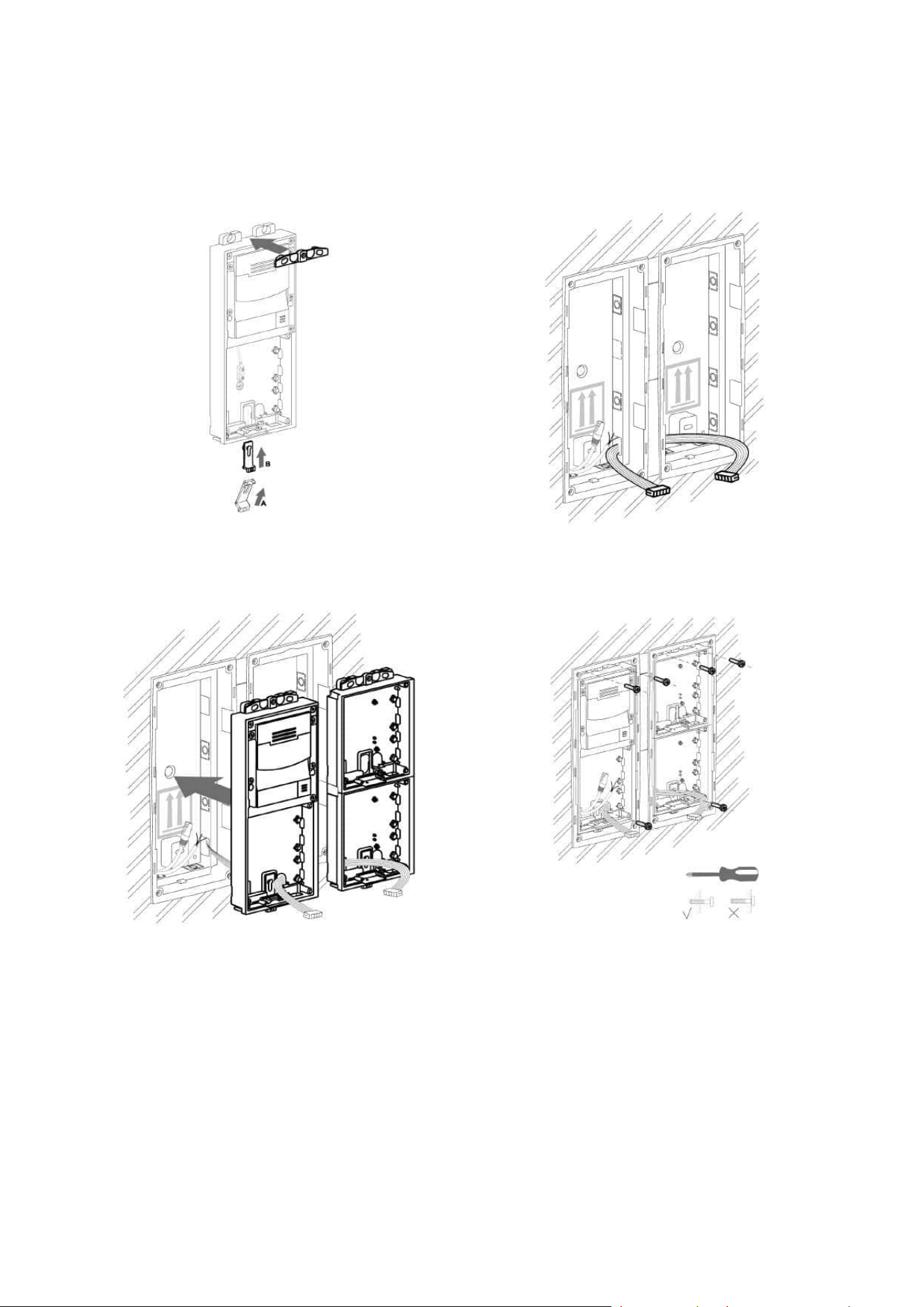
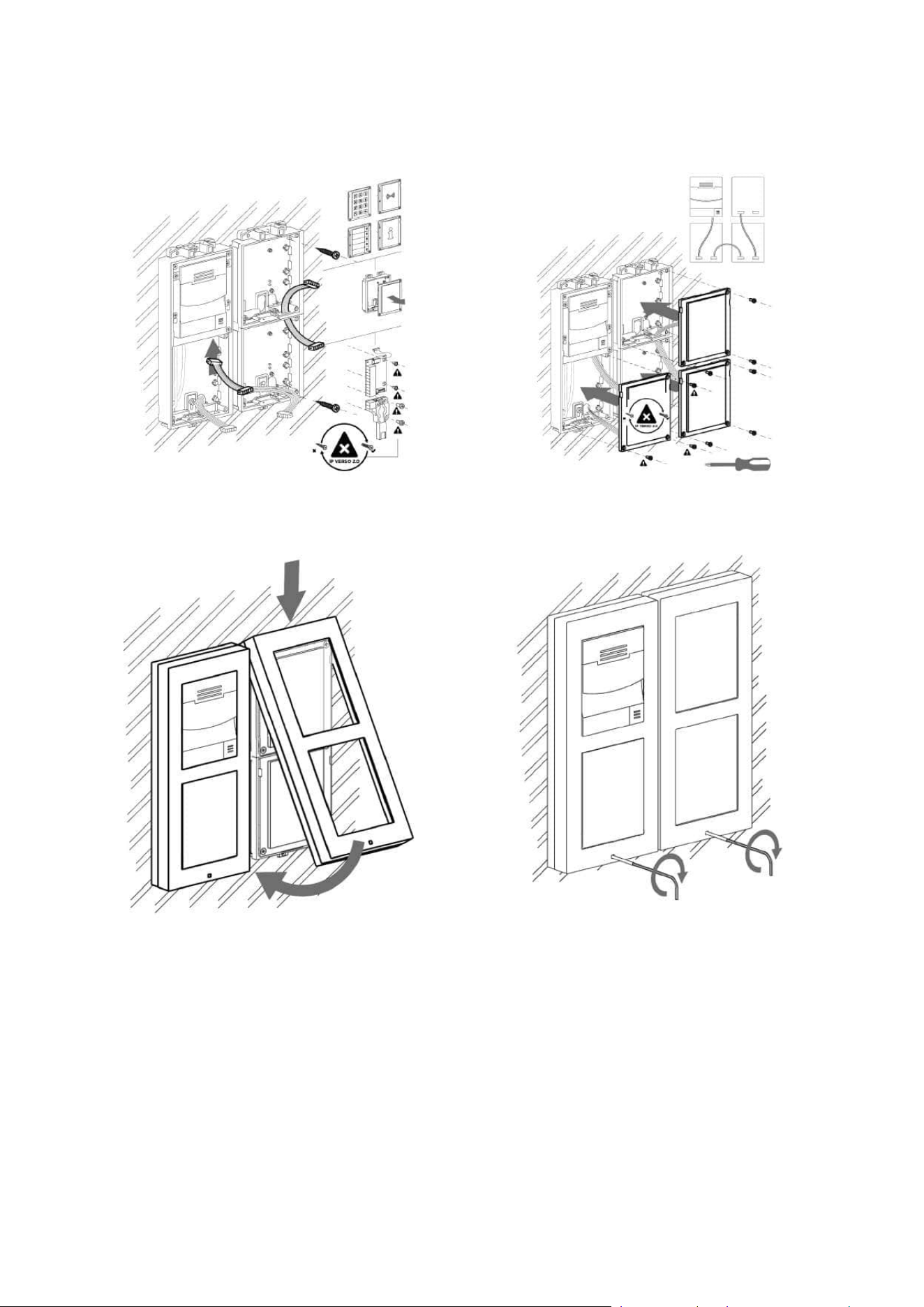
Flush module mounting
Installation manual 2N® IP Verso 2.0
94 / 213
Installation manual 2N® IP Verso 2.0
95 / 213
Installation manual 2N® IP Verso 2.0
96 / 213
2.2.1.4 Three Module Box
Flush mounting box – classic bricks
Installation manual 2N® IP Verso 2.0
97 / 213
Installation manual 2N® IP Verso 2.0
98 / 213
•
Warning!
Make sure that the flush mounting box is slightly above the wall surface not
aligning with the wall. A wrong installation may lead to water penetration and
subsequent damage of the device. Use the side protrusions to achieve the proper
flush mounting.
•
Caution
Break off the side protrusions when the walling material has hardened.

Installation manual 2N® IP Verso 2.0
99 / 213
Installation manual 2N® IP Verso 2.0
100 / 213
Flush mounting box – plasterboard
Installation manual 2N® IP Verso 2.0
101 / 213
Installation manual 2N® IP Verso 2.0
102 / 213
Flush module mounting
Installation manual 2N® IP Verso 2.0
103 / 213
Installation manual 2N® IP Verso 2.0
104 / 213
Installation manual 2N® IP Verso 2.0
105 / 213
2.2.1.5 More Three Module Boxes
Flush mounting box – classic bricks
Installation manual 2N® IP Verso 2.0
106 / 213
Installation manual 2N® IP Verso 2.0
107 / 213

Installation manual 2N® IP Verso 2.0
108 / 213
•
Warning!
Make sure that the flush mounting box is slightly above the wall surface not
aligning with the wall. A wrong installation may lead to water penetration and
subsequent damage of the device. Use the side protrusions to achieve the proper
flush mounting.
•
Caution
Break off the side protrusions when the walling material has hardened.

Installation manual 2N® IP Verso 2.0
109 / 213
Installation manual 2N® IP Verso 2.0
110 / 213
Flush mounting box – plasterboard
Installation manual 2N® IP Verso 2.0
111 / 213
Installation manual 2N® IP Verso 2.0
112 / 213
Flush module mounting
Installation manual 2N® IP Verso 2.0
113 / 213
Installation manual 2N® IP Verso 2.0
114 / 213
Installation manual 2N® IP Verso 2.0
115 / 213

Installation manual 2N® IP Verso 2.0
116 / 213
•
•
•
•
•
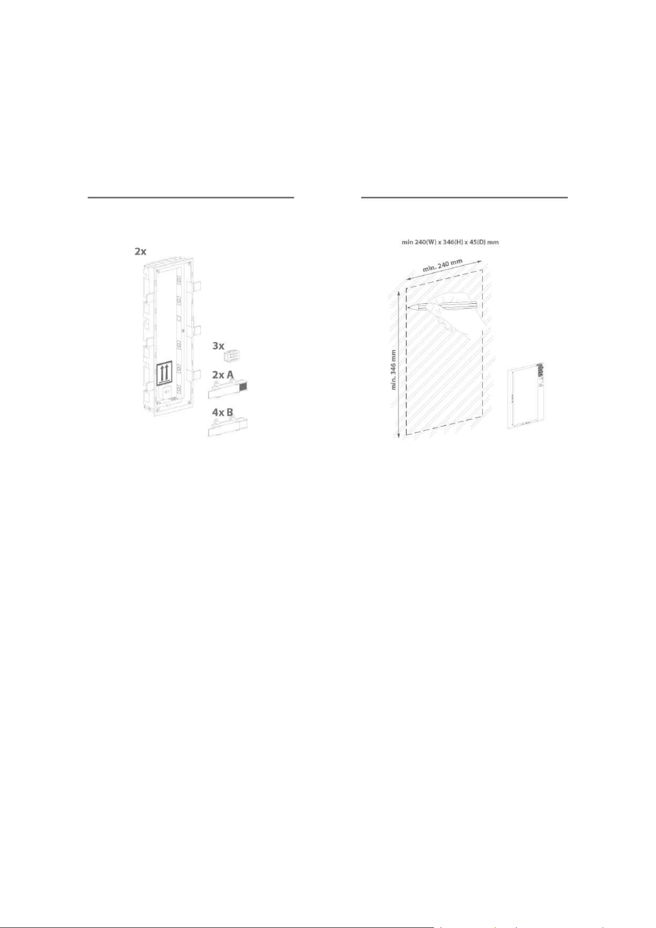
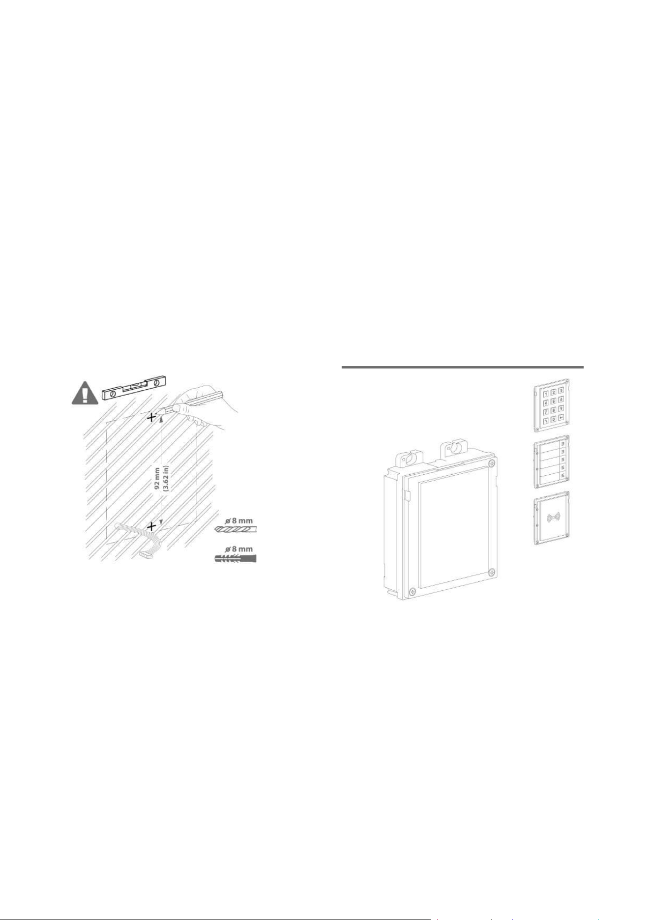
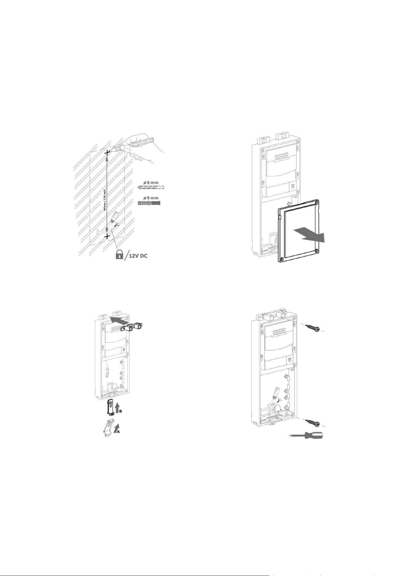
2.2.2 Surface Mounting
List of Necessary Components
concrete and steel structures, barrier columns, interiors, etc.
What you need for installation:
2N
®
IP Verso 2.0 plus appropriate frames
1 module: frame Part No.9155021
2 modules: frame Part No.9155022
3 modules: frame Part No.9155023
Backplates (Part Nos.9155061–9155067) are required for metal,
glass and plaster surfaces as well as other uneven surfaces,
depending on the module count.
Installation manual 2N® IP Verso 2.0
118 / 213
Installation manual 2N® IP Verso 2.0
119 / 213

Installation manual 2N® IP Verso 2.0
120 / 213
Installation manual 2N® IP Verso 2.0
121 / 213
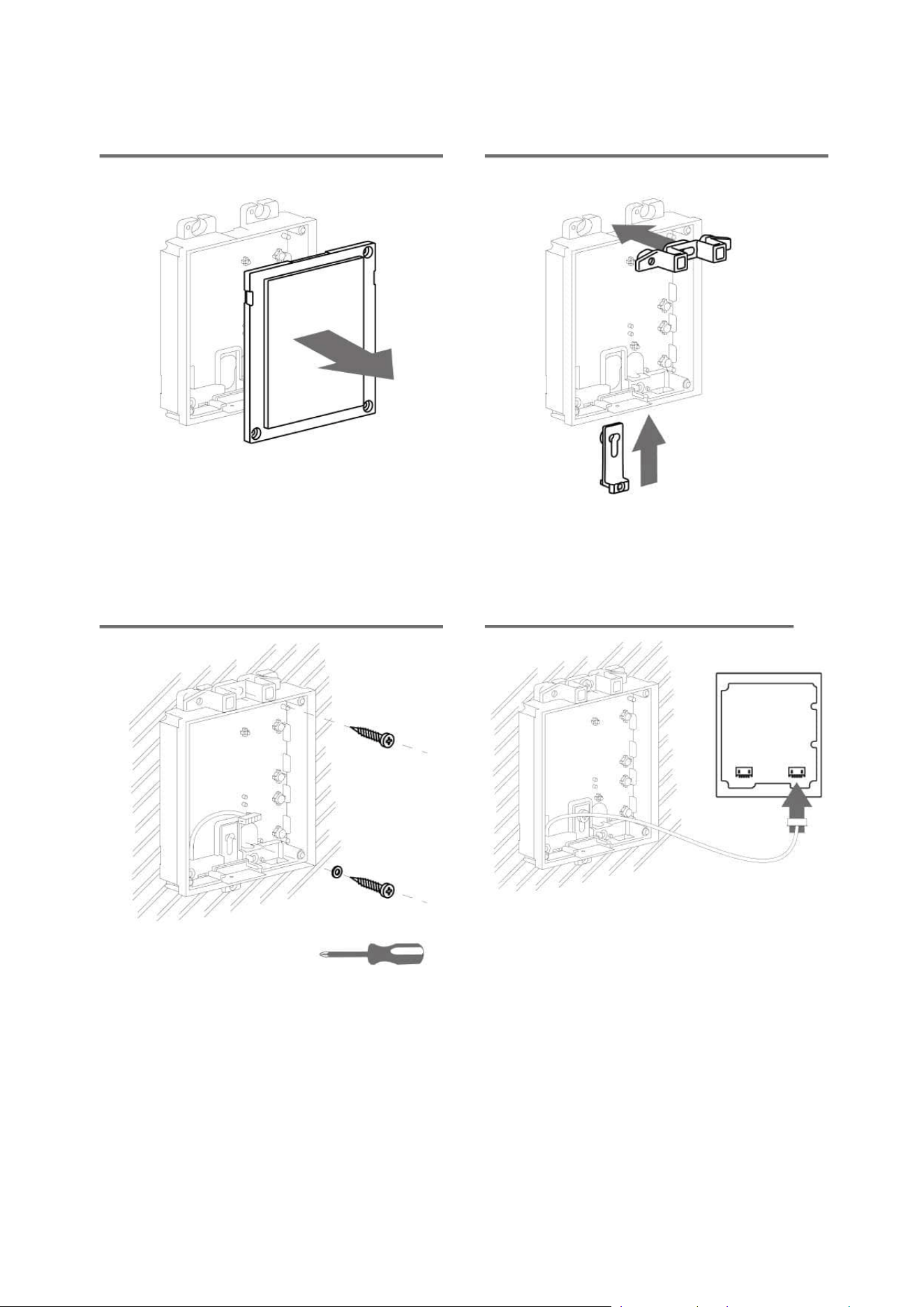
2.2.2.2 Two Module Box
Surface module mounting
Installation manual 2N® IP Verso 2.0
122 / 213
Installation manual 2N® IP Verso 2.0
123 / 213
Installation manual 2N® IP Verso 2.0
124 / 213
2.2.2.3 More Two Module Boxes
Surface module mounting
Installation manual 2N® IP Verso 2.0
125 / 213
Installation manual 2N® IP Verso 2.0
126 / 213
Installation manual 2N® IP Verso 2.0
127 / 213
2.2.2.4 Three Module Box
Surface module mounting
Installation manual 2N® IP Verso 2.0
128 / 213
Installation manual 2N® IP Verso 2.0
129 / 213
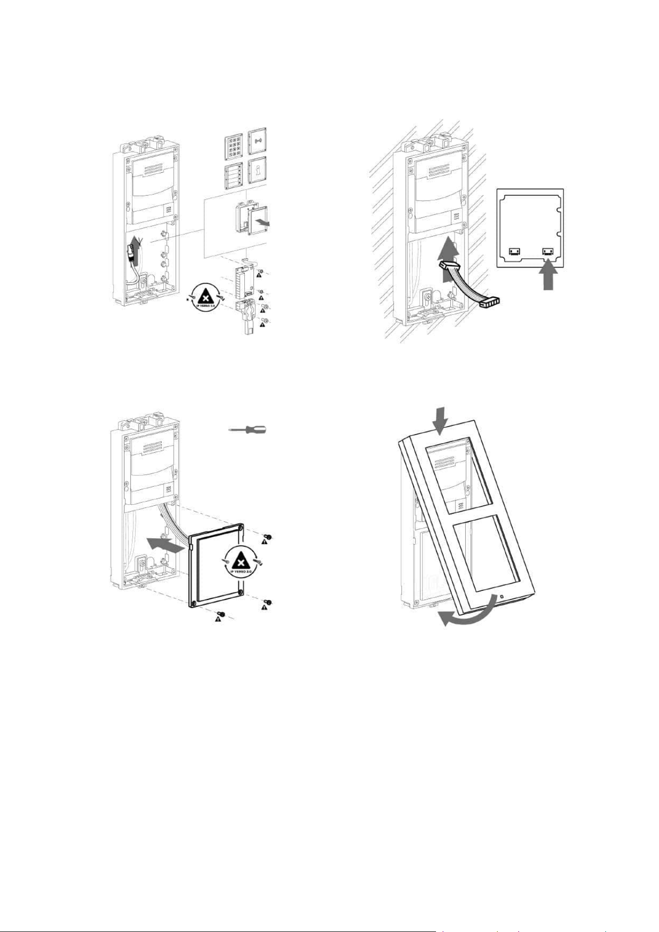
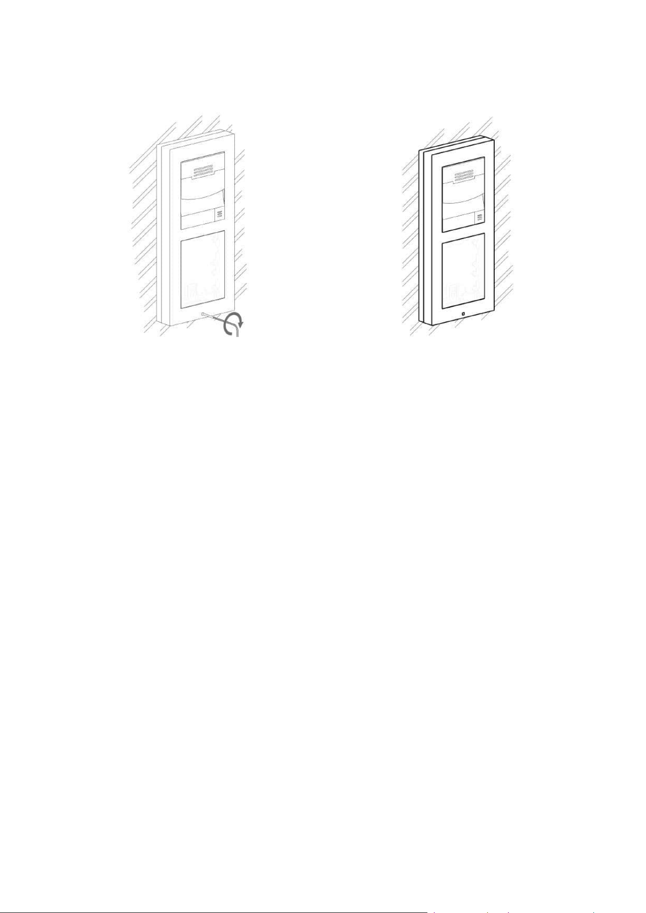
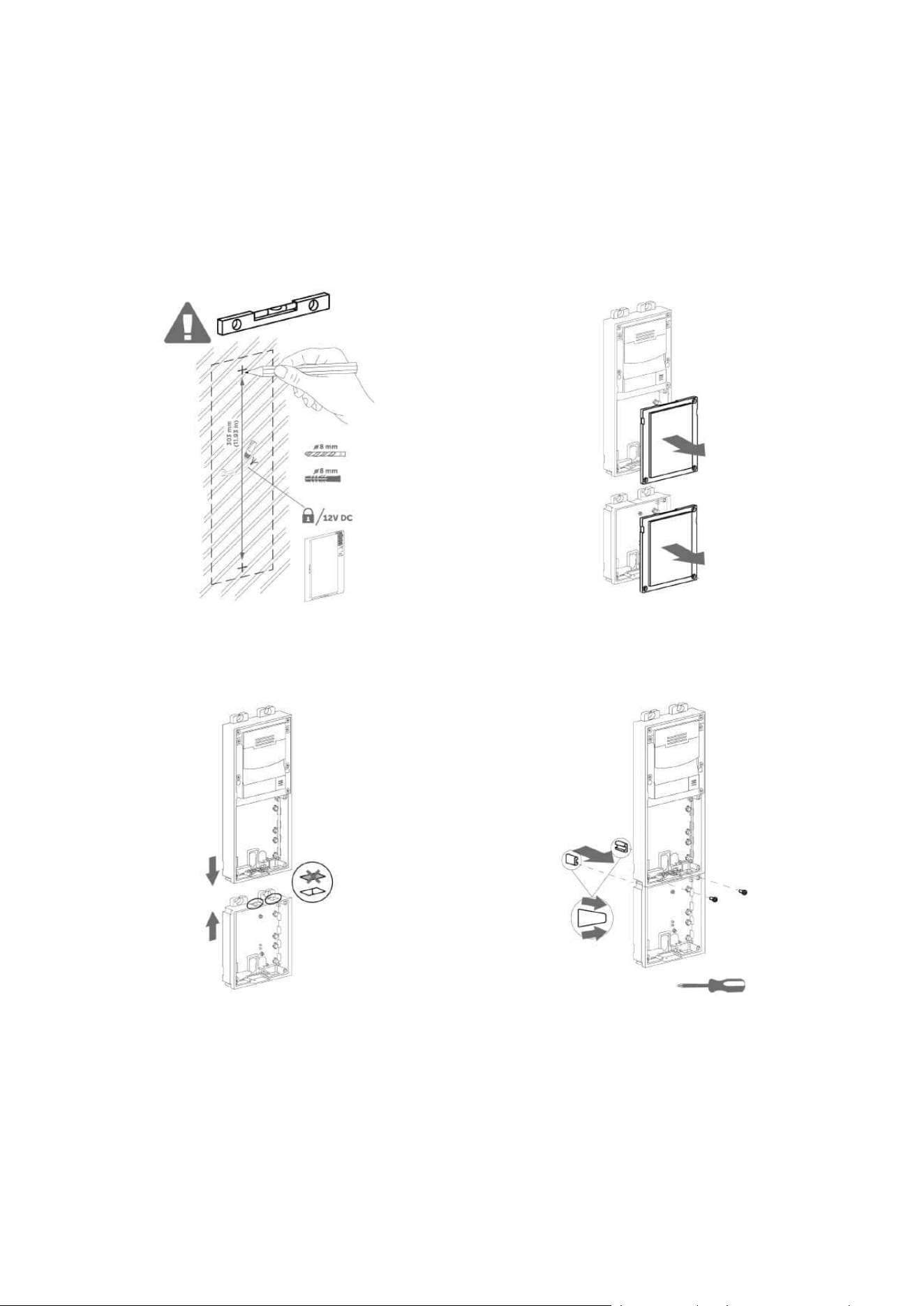
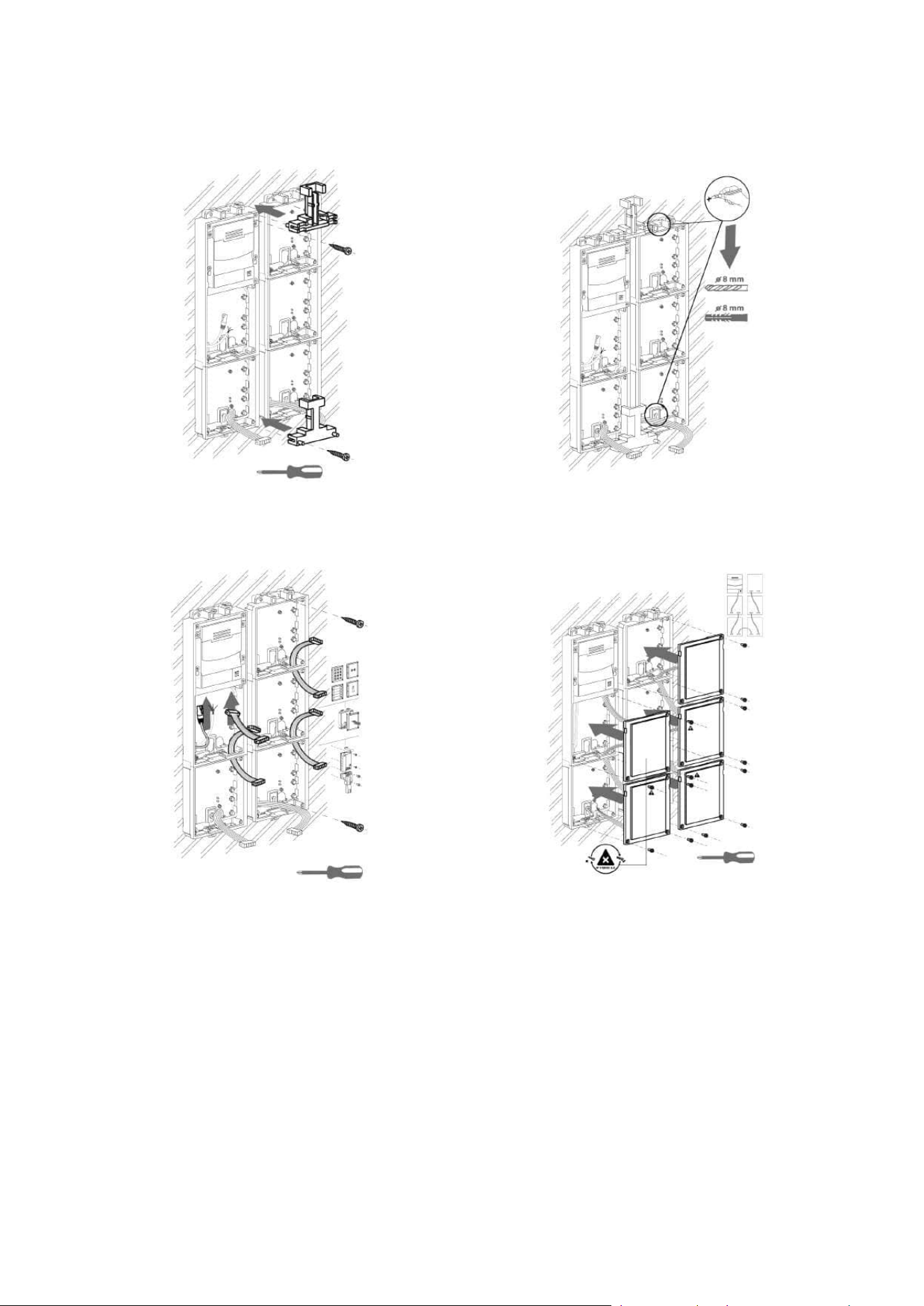
2.2.2.5 More Three Module Boxes
Surface module mounting
Installation manual 2N® IP Verso 2.0
130 / 213
Installation manual 2N® IP Verso 2.0
131 / 213
Installation manual 2N® IP Verso 2.0
132 / 213
Installation manual 2N® IP Verso 2.0
133 / 213
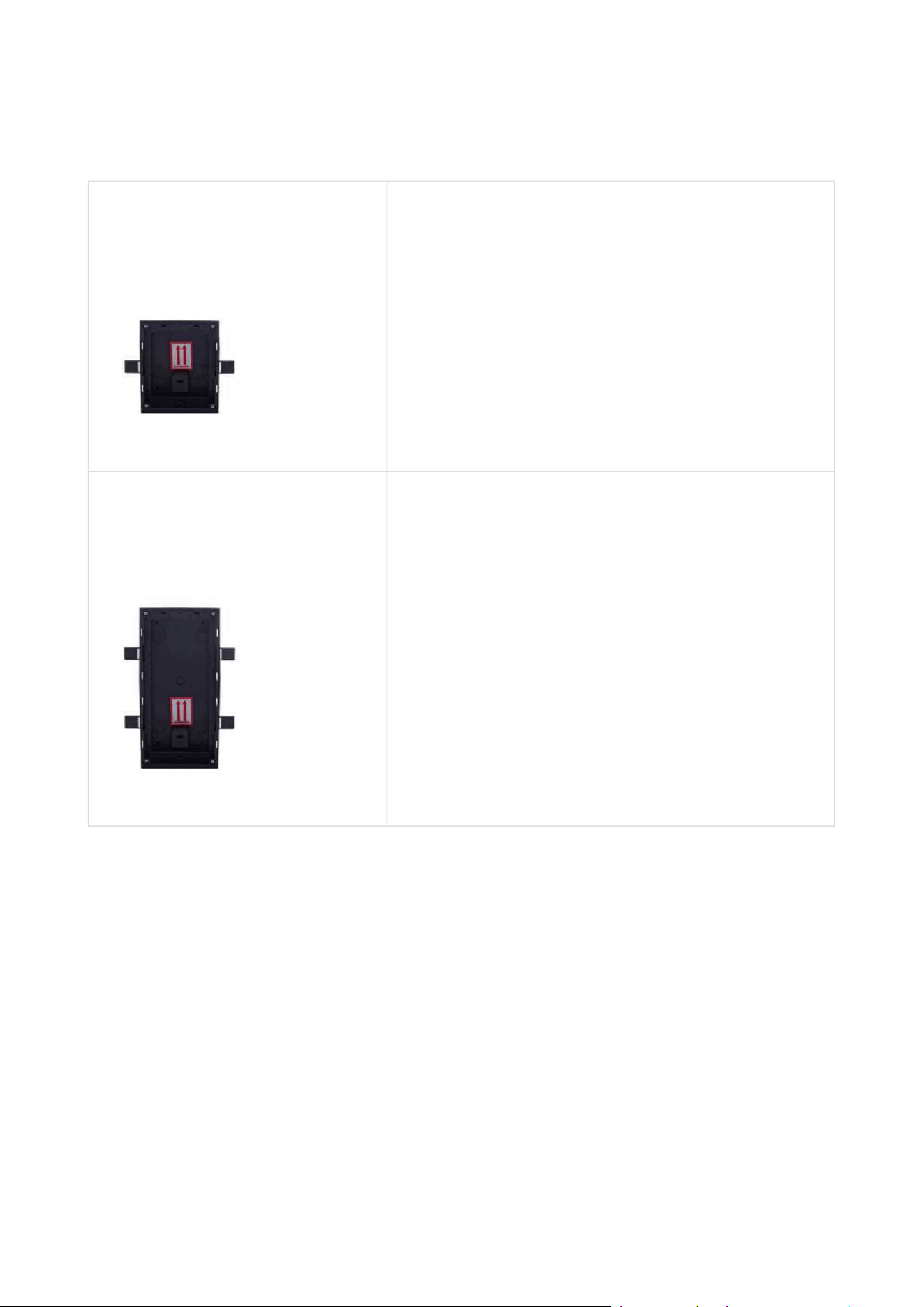
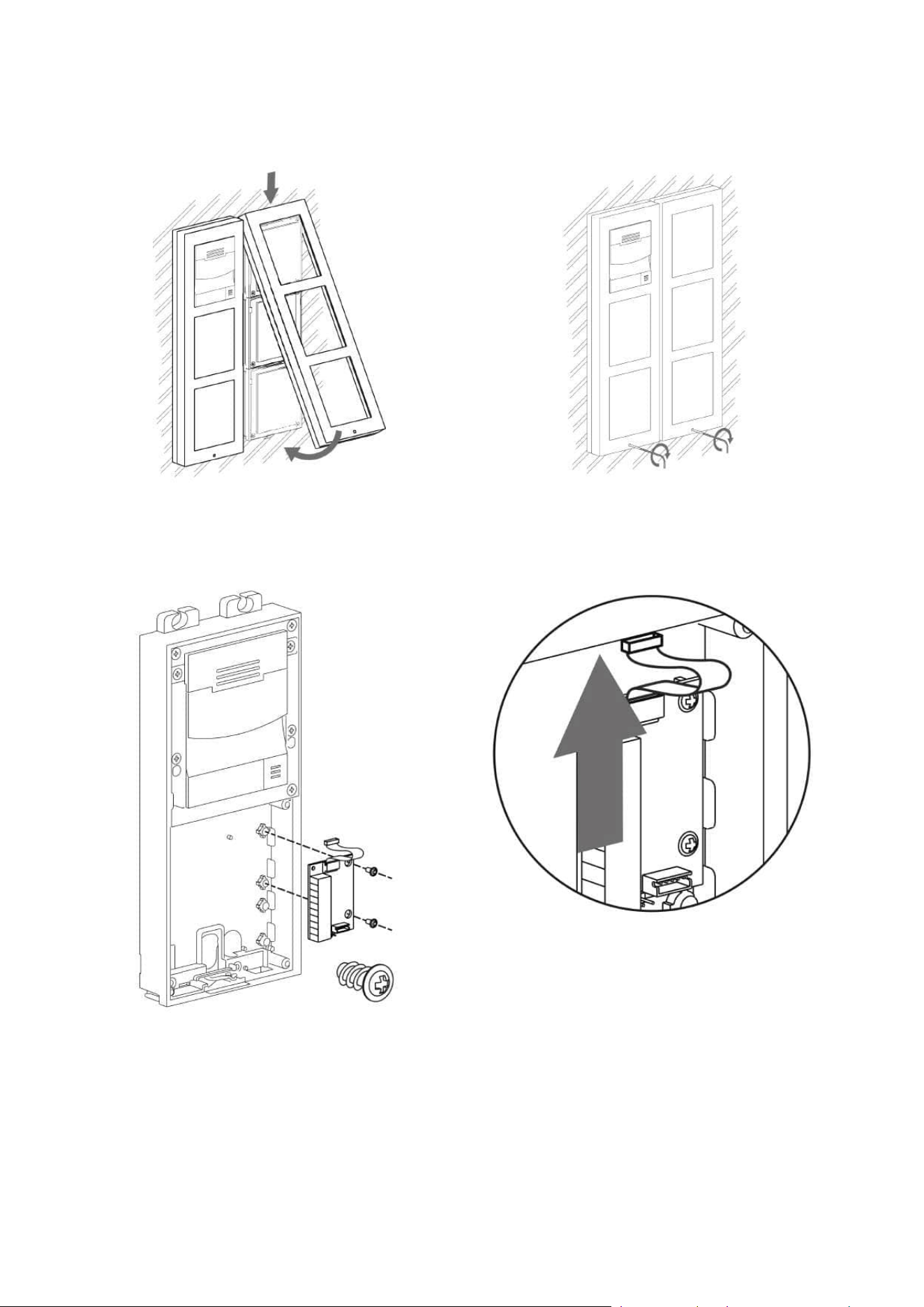
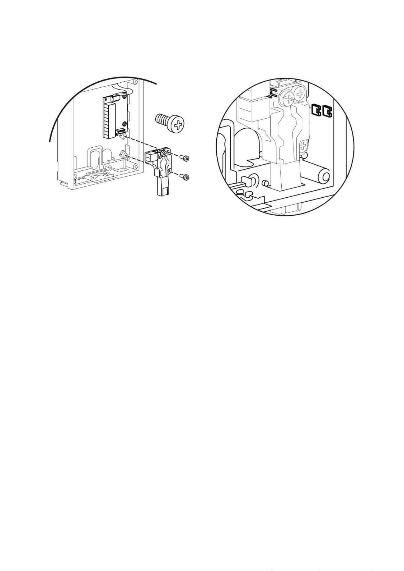
2.2.4 Tamper and I/O Modules
Installation manual 2N® IP Verso 2.0
134 / 213
Installation manual 2N® IP Verso 2.0
135 / 213
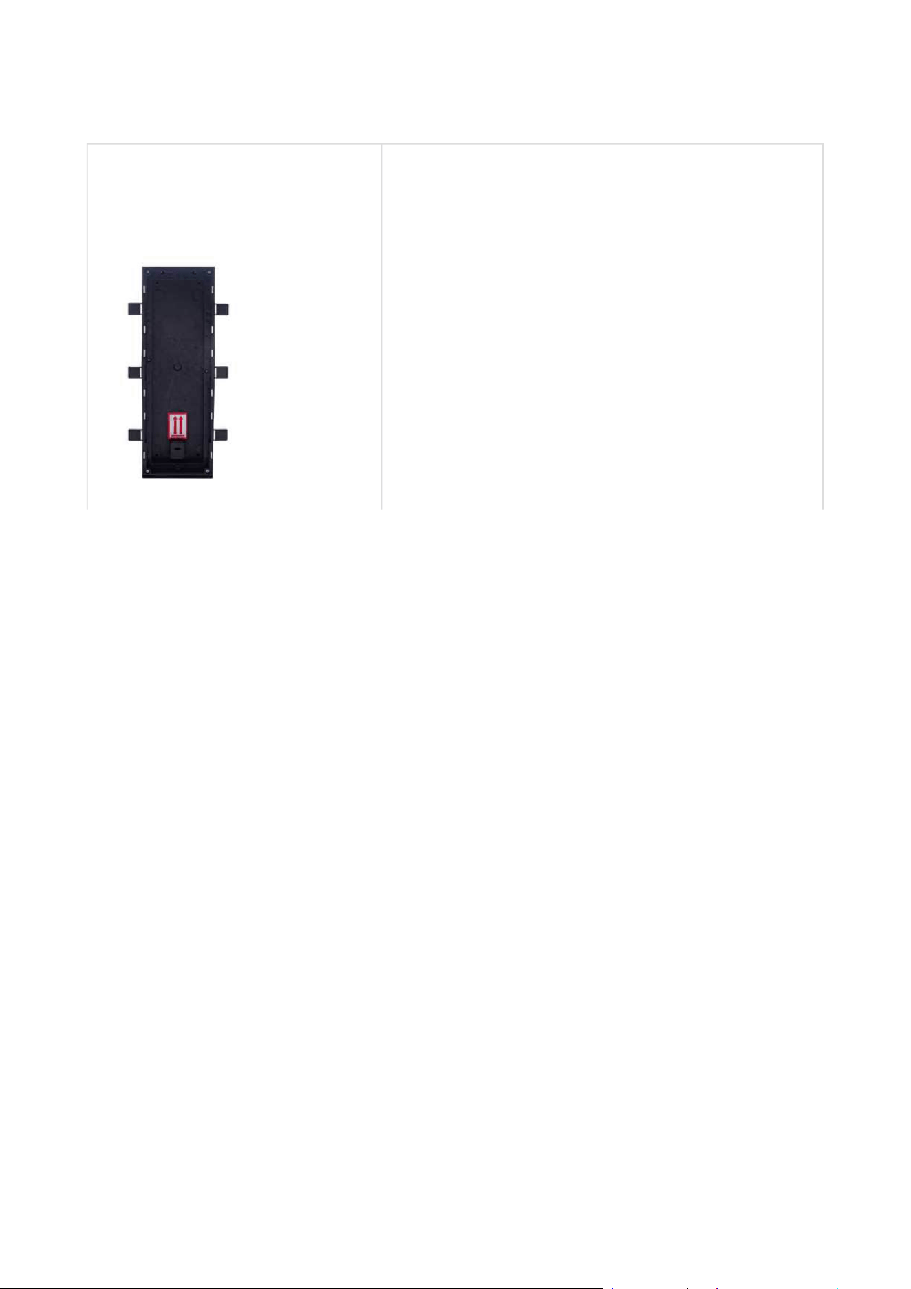
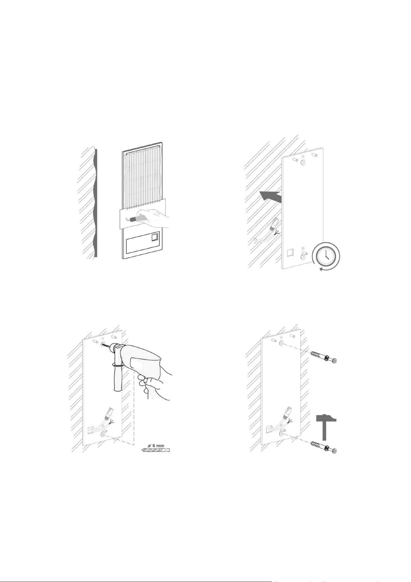
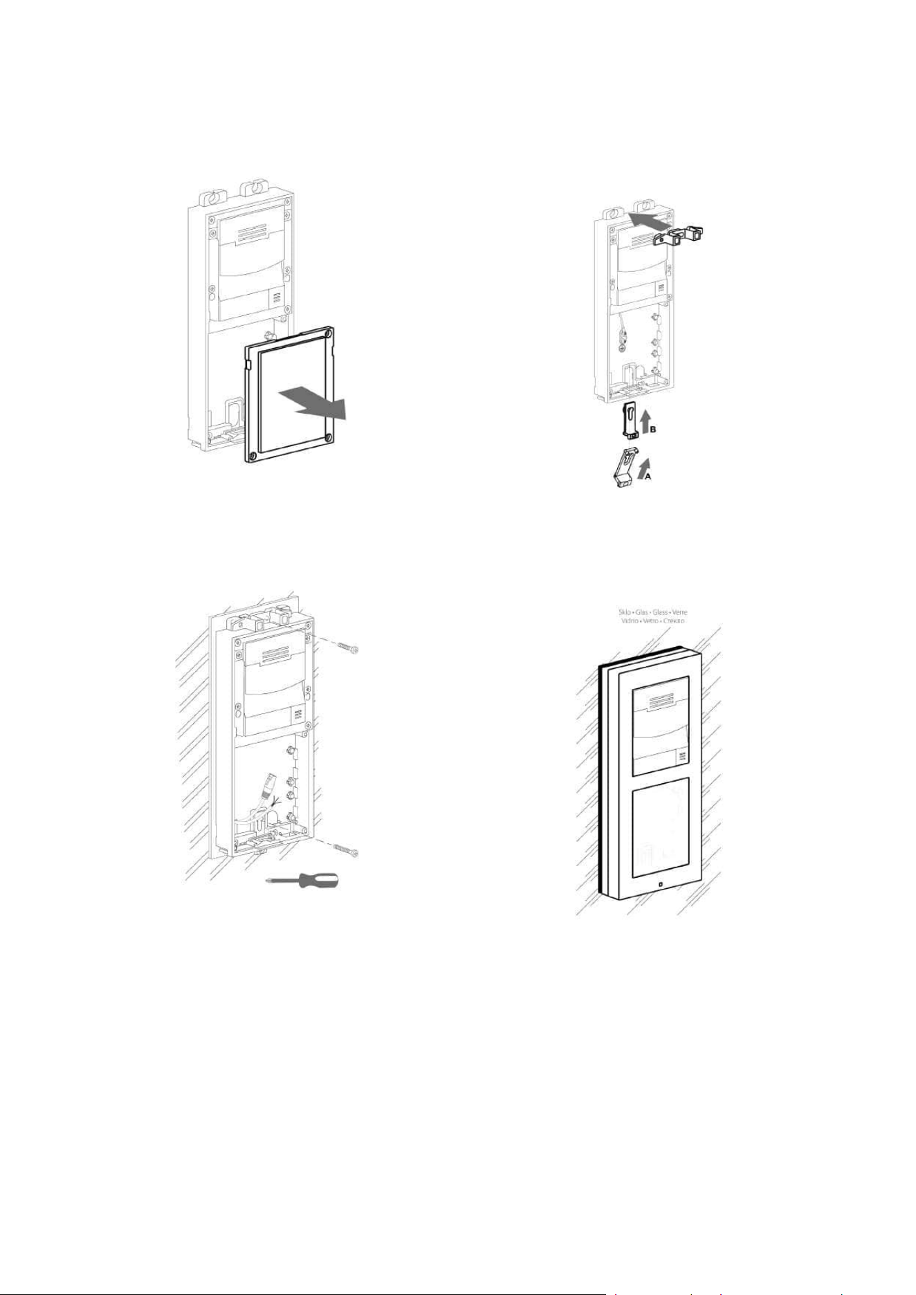
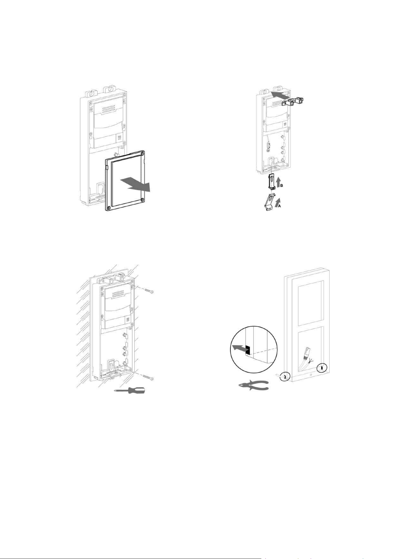
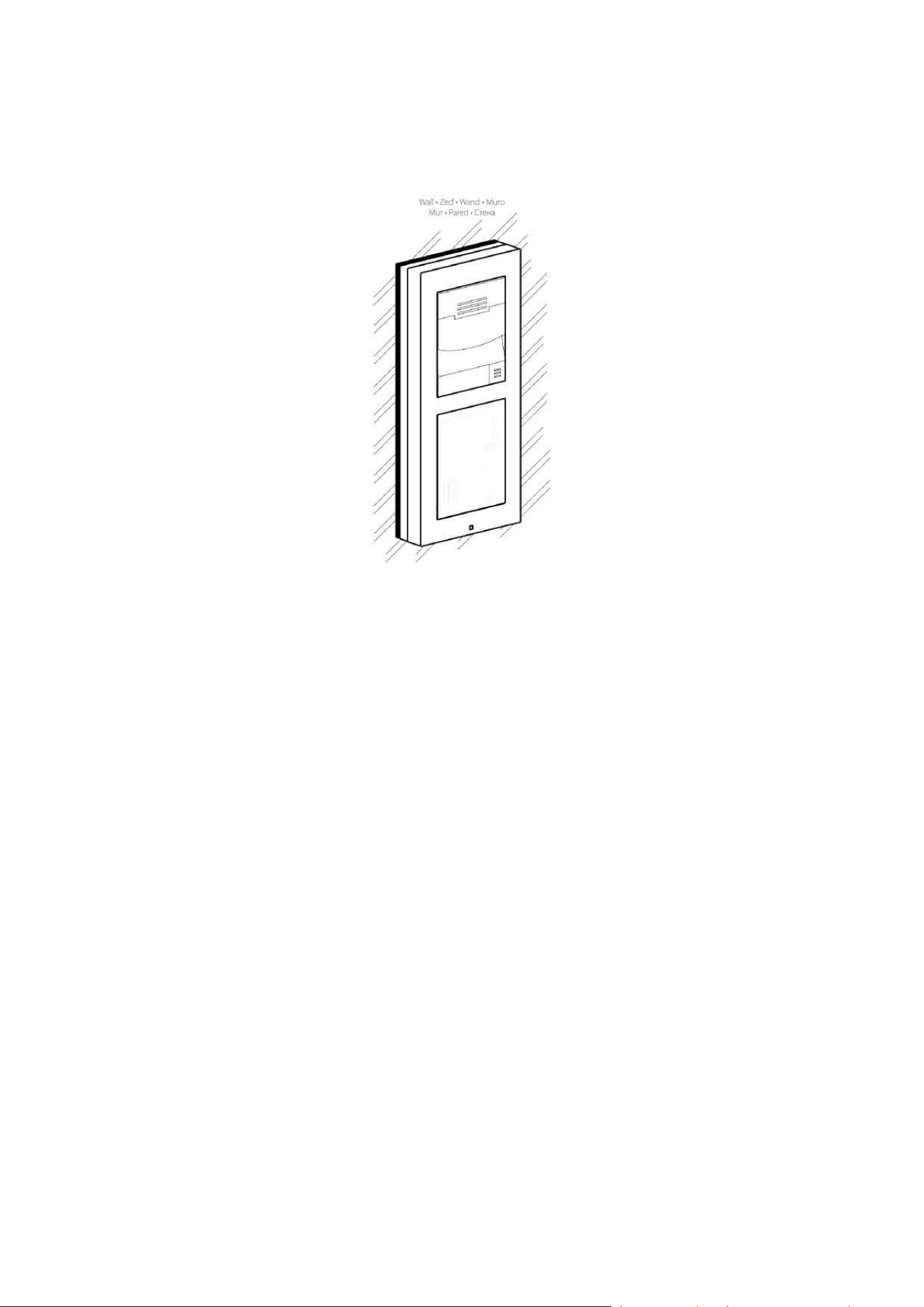
2.2.3 Example of Mounting Plate Installation
Wall installation
Installation manual 2N® IP Verso 2.0
136 / 213
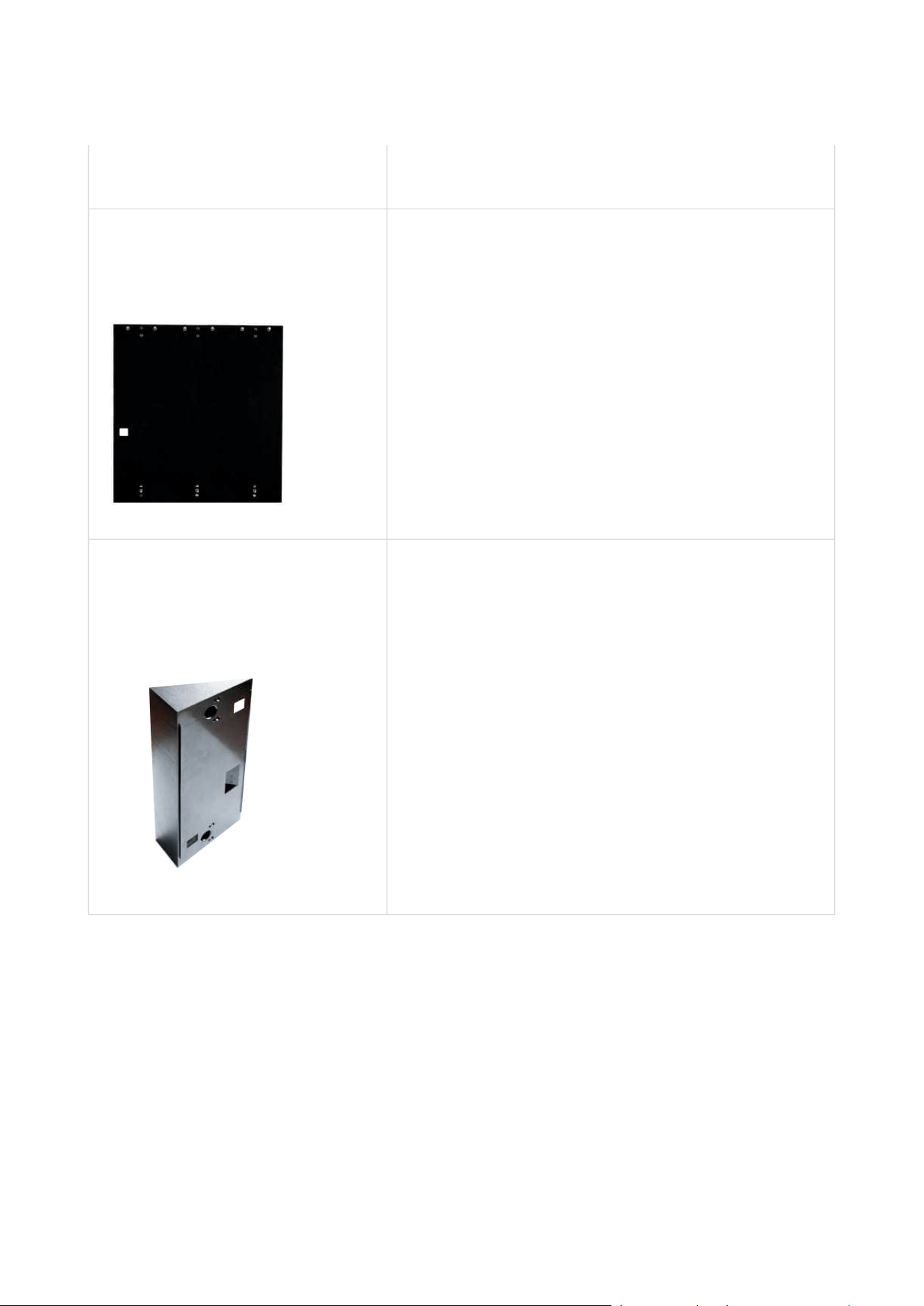
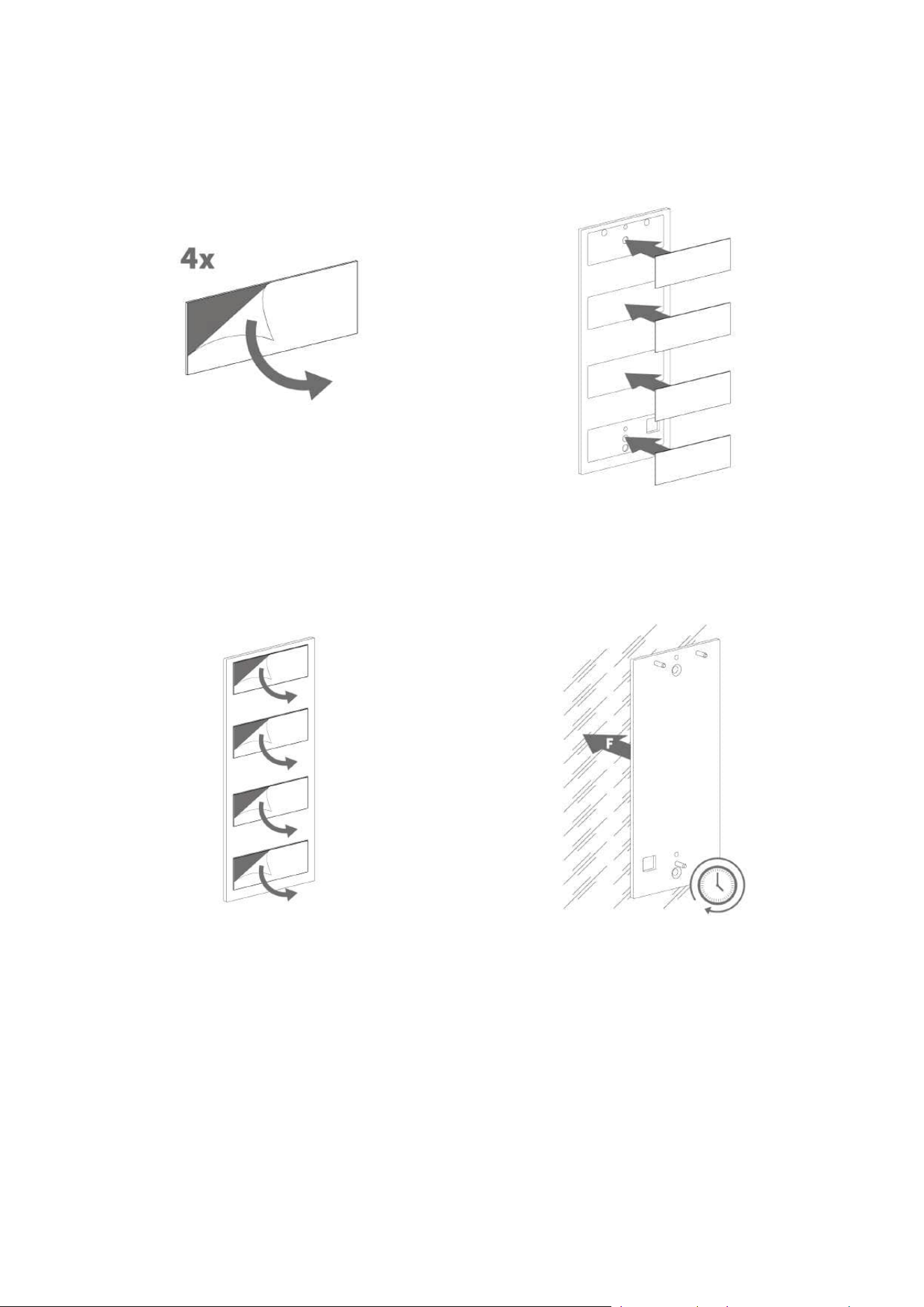
Glass surface installation
Installation manual 2N® IP Verso 2.0
137 / 213
Installation manual 2N® IP Verso 2.0
138 / 213
Installation manual 2N® IP Verso 2.0
139 / 213
•
•
•
•
•
•
•
•
•
•
•
•
•
2.2.5 Module Dimensions
Frames
9155011–Flush mounting frame, 1 module
9155012–Flush mounting frame, 2 modules
9155013–Flush mounting frame, 3 modules
9155021–Surface mounting frame, 1 module
9155022–Surface mounting frame, 2 modules
9155023–Surface mounting frame, 3 modules
Backplates
9155061– 1 module
9155062– 2 modules
9155063– 3 modules
9155064– 2x2 modules
9155065– 3x2 modules
9155066– 2x3 modules
9155067– 3x3 modules

Installation manual 2N® IP Verso 2.0
140 / 213
2.3 Electric Installation
This subsection describes how to connect the 2N
®
IP Verso 2.0 main unit to the power supply
and LAN and how to connect other elements.
Main Unit
Power Supply Connection
2N
®
IP Verso 2.0 can be powered either from an external 12 V / 2 A DC source or directly from the
LAN equipped with PoE 802.3af supporting network elements. Owing to different power outputs,
the power supply selection affects the maximum count and applicability of the modules
connected of the main unit.
External power supply
For reliability reasons, use a 12 V ±15% SELV supply dimensioned to the current consumption as
required for feeding of the main unit and connected extending modules.
Current consumption
[A]
Part number Avaible power output
[W]
2 91341481E 24
3 36
PoE Power Supply
2N
®
IP Verso 2.0 is compatible with the PoE 802.3af (Class 0–12,95 W) technology and can be fed
directly from the LAN via the compatible network elements. If your LAN does not support this
technology, insert a PoE injector, Part No. 91378100, between2N
®
IP Verso 2.0 and the nearest
•
Caution
The device must be part of the electrical system of the building.
•
Caution
The external power supply should meet the PS2/LPS power supply class
requirements.

Installation manual 2N® IP Verso 2.0
141 / 213
network element. This power supply provides2N
®
IP Verso 2.0 with 12 W for feeding of the main
unit and connected modules.
Combined Power Supply
2N
®
IP Verso 2.0 can be fed from an external power supply and PoE at the same time. In this
configuration, the maximum power for the connected modules is available.
LAN Connection
2N
®
IP Verso 2.0 is connected to the Local Area Network (LAN) via the UTP/STP cable (Cat 5e or
higher) terminated with an RJ-45 (LAN) connector. As the device is equipped with the Auto-MDIX
function, both the straight and crossed cable can be used.
•
•
Caution
We recommend the use of a LAN surge protection.
We recommend the use of a shielded SSTP Ethernet cable with a shielded RJ-45
connector connected to the switch (with the grounding option) via the same
shielded connector. This makes the device perfectly grounded.
•
Tip
Remove the connector protecting cover to pass through the UTP/STP cable RJ
terminal to the device box more easily.
•
Warning
This product cannot be connected directly to the telecommunications lines (or
public wireless LANs) of any telecommunication carriers (e.g. mobile
communications carriers, fixed communications carriers, or internet providers). In
the case of connecting this product to the Internet, be sure to connect it via a
router.
Installation manual 2N® IP Verso 2.0
142 / 213
•
•
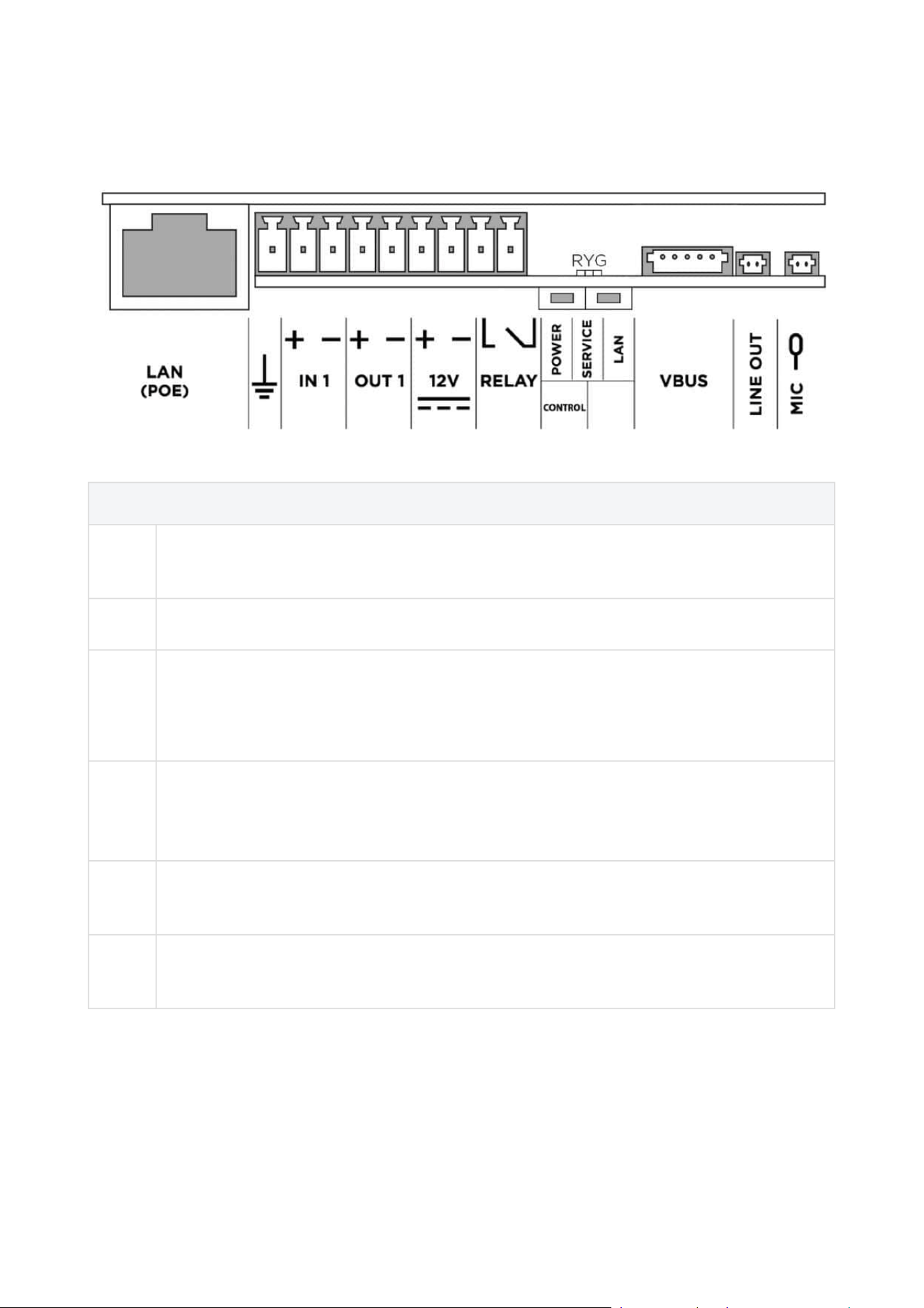
Main Unit Connector Configuration
Legend
LAN
(PoE)
LAN (PoE according to 802.3af) connector
GND Grounding terminal
IN1 IN1 terminals for input in passive/ active mode(−30 V to +30 V DC)
OFF = open OR U
IN
> 1.5 V
ON = closed contact OR U
IN
< 1.5 V
OUT1
OUT1 terminals of active input for2N
®
Security Relay or electric lock connection 8
up to 12 V DC depending on power supply (PoE: 10 V; adaptor: power supply voltage
minus 2 V), max. 600 mA
12 V /
2 A
External 12 V / 2 A DC supply terminals
RELA
Y
RELAY terminals with accessible 30 V / 1 A AC/DC NO contact.

Installation manual 2N® IP Verso 2.0
143 / 213
POWE
R/
SERVI
CE/
LAN
LED indicators(red/green/yellow)
CONT
ROL
Button for resetting the device to factory settings
BOOT The button is used for advanced diagnostic hardware operations, but does not
respond to a common user’s press.
VBUS VBUS connector
LINE
OUT
LINE OUT connector(1 V
RMS
). Connector type JST SHR-02V-S.
MIC MIC connector for microphone connection
•
Caution
We recommend that a grounding cable of the cross-section of 1.5 mm
2
is used.
Installation manual 2N® IP Verso 2.0
144 / 213
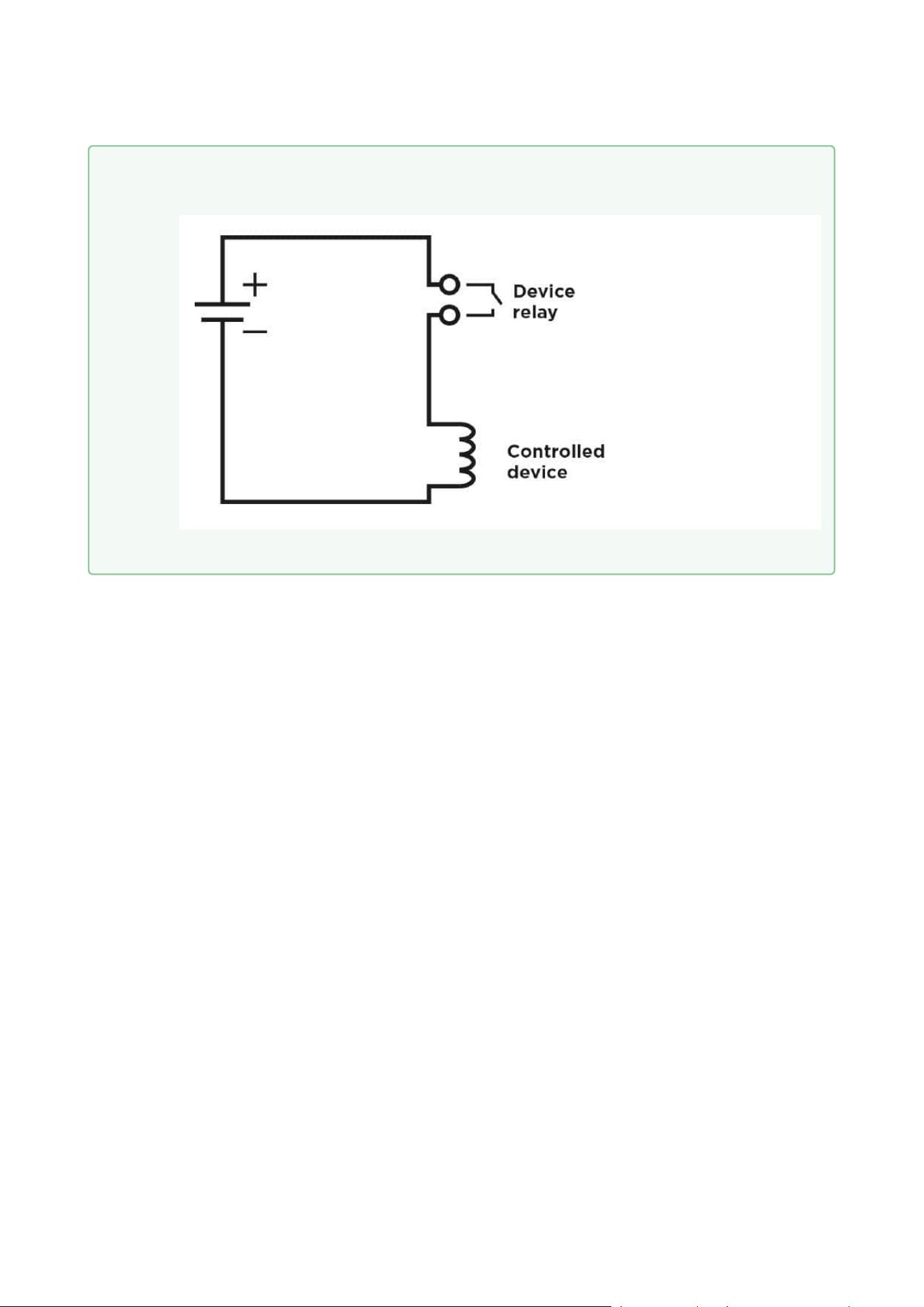
•
Tip
Relay output wiring diagram
Wiring diagram for making of the electric circuit of the device to be controlled
Installation manual 2N® IP Verso 2.0
145 / 213
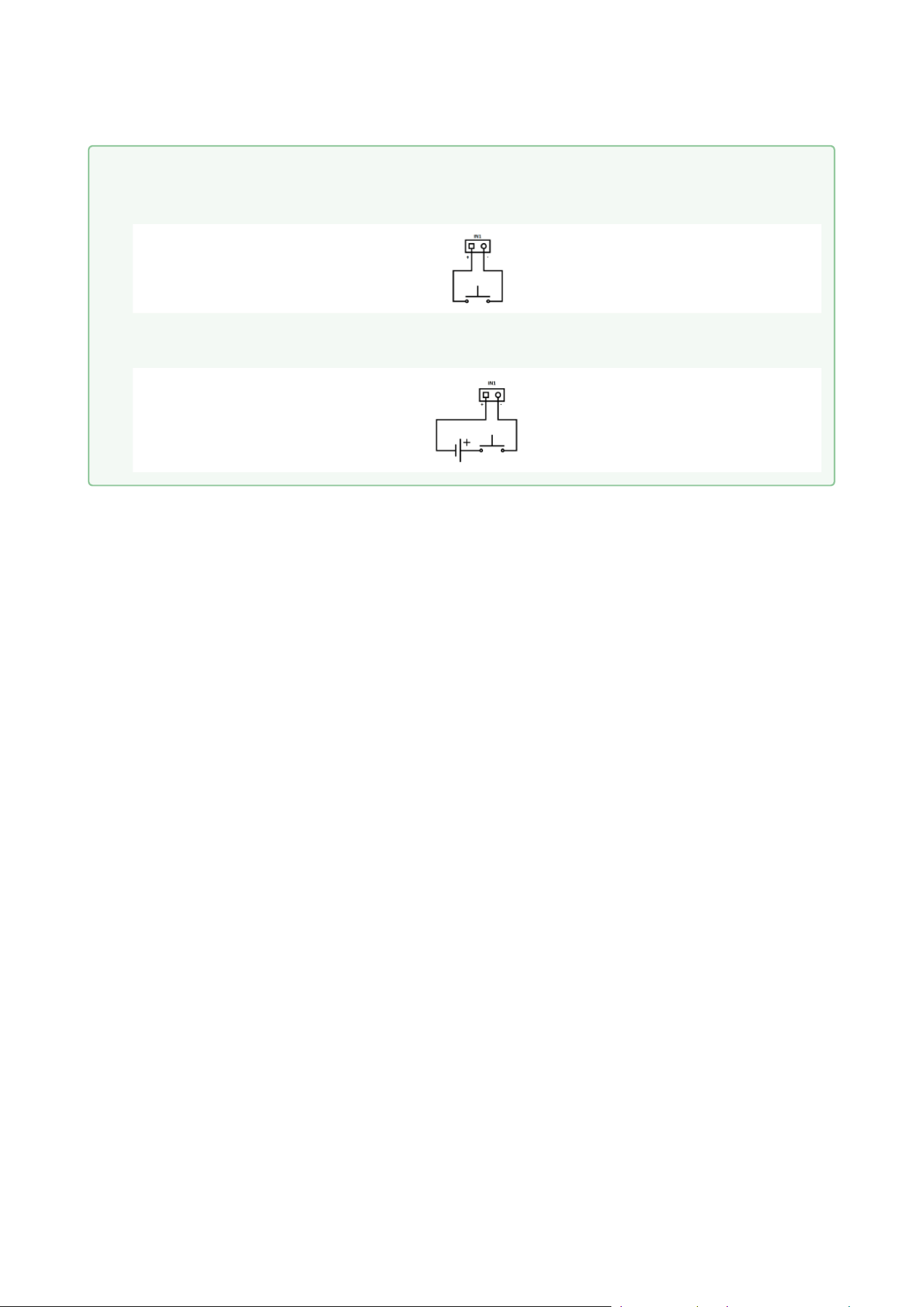
•
•
Tip
Wiring Diagram of IN1 connector in active mode
Wiring Diagram of IN1 connector in passive mode
Installation manual 2N® IP Verso 2.0
146 / 213
Available Switches
Location Name Description
Main Unit RELAY Passive switch:make contact, up to 30 V /
1 A AC/DC
OUT Active switch output:8 to 12 V DC
according to power supply (PoE: 10 V;
adapter: source voltage minus 2 V), up to
600 mA
I/O* Module
(Part No. 9155034)
ext.relay1 Passive switch:make and break contact,
up to 30 V / 1 A AC/DC Used for connection
of non-critical devices only (lights, e.g.).
ext.relay2 Passive switch:make and break contact,
up to 30 V / 1 A AC/DC Used for connection
of non-critical devices only (lights, e.g.).
You can use any number of the modules marked with *.
•
Security
The 12V output is used for lock connection. If, however, the unit (2N IP Intercom,
2N Access Unit) is installed where unauthorized tampering may happen (building
envelopes), we strongly recommend that 2N
®
Security Relay (Part No. 9159010) be
used for enhanced installation security.
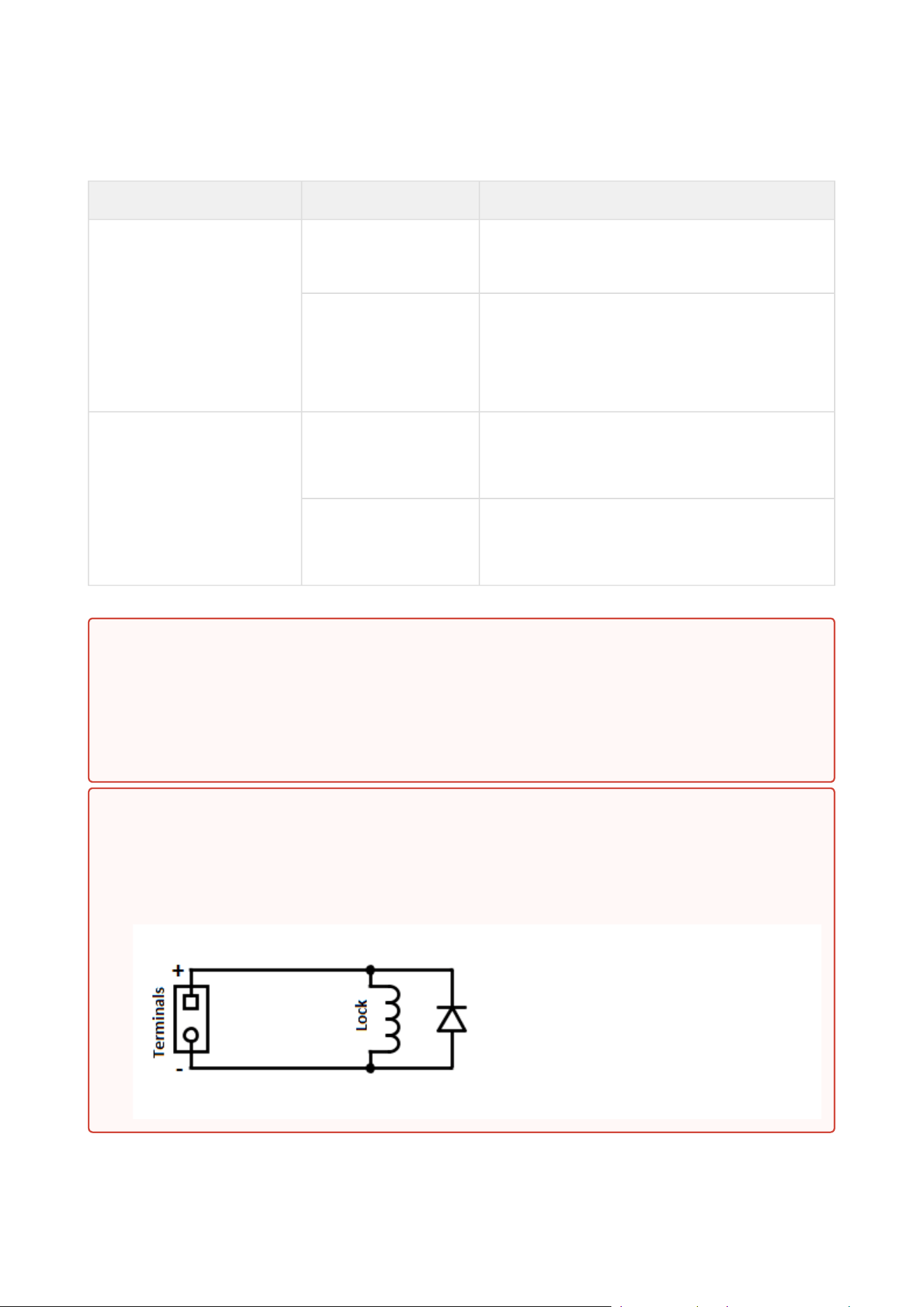
Warning
If a coil containing device is connected, e.g. a relay / electromagnetic lock, it is necessary
to protect the intercom output against voltage peak while switching off the induction
load. For this way of protection, we recommend a 1 A / 1000 V diode (e.g., 1N4007,
1N5407, 1N5408) connected antiparallel to the device.
Installation manual 2N® IP Verso 2.0
148 / 213
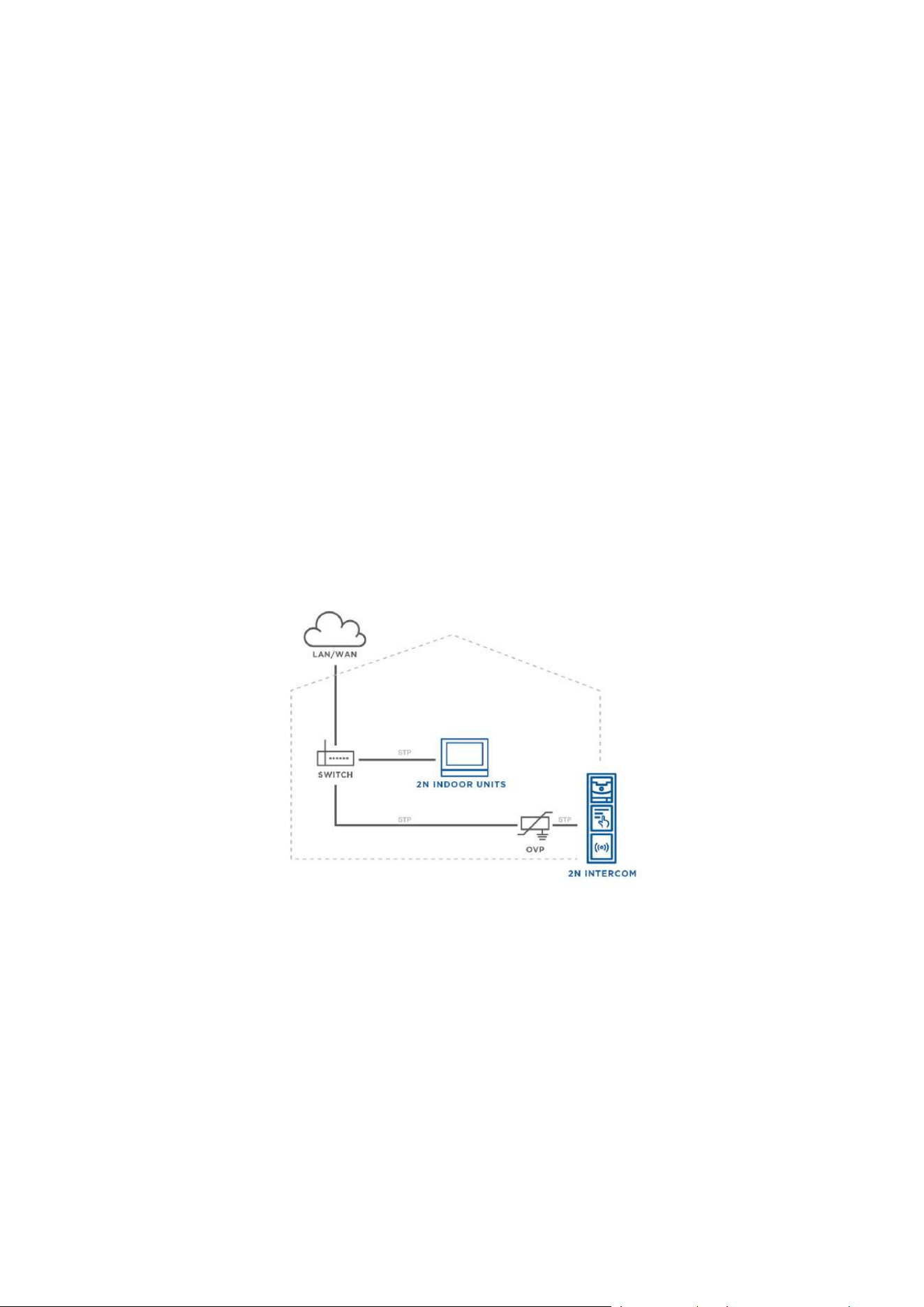
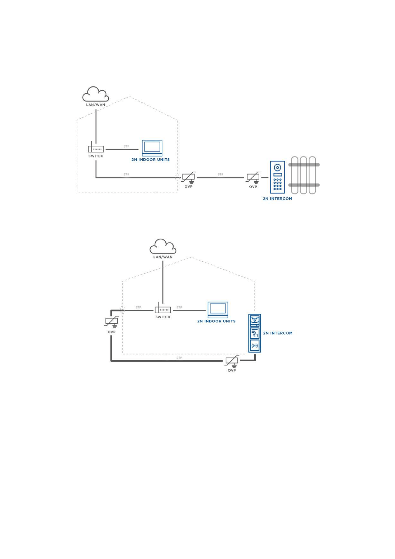
2.3.1 Overvoltage Protection
Recommendations for Additional Overvoltage Protector Installation
If running:
a) outside a building,
b) on/in an outer wall or roof,
the 2N device wiring may be exposed to atmospheric effects resulting in overvoltage that may
subsequently damage any devices installed outside the building, on its outer wall or roof.
Overvoltage may damage devices connected to these wires and installed inside the building as
well. Therefore, we recommend that additional surge protectors be installed on all the wires
leading outside buildings, on outer walls or roofs, namely:
a) as close as possible to the device installed outside the building or on its outer wall/roof,
b) as close as possible to the point where the wires leave the building.
Examples of overvoltage protection:
Installation manual 2N® IP Verso 2.0
149 / 213
•
•
•
•
OVP = overvoltage protection
2.4 Extending Module Connection
2N
®
IP Verso 2.0 allows you to connect the following extending modules:
Infopanel
Keypad
Touch Keypad
RFID Card Reader 125 kHz

Installation manual 2N® IP Verso 2.0
150 / 213
•
•
•
•
•
•
•
•
•
•
•
•
•
•
•
•
•
RFID Card Reader 13.56 MHz, NFC Support
Secured RFID Card Reader 13.56 MHz, NFC Support
Bluetooth & RFID Reader 125kHz, 13.56 MHz, NFC
Bluetooth & RFID Reader 125kHz, secured 13.56 MHz, NFC
Touch Keypad & RFID Reader 125 kHz, 13.56MHz, NFC
Touch Keypad & RFID Reader 125 kHz, secured 13.56 MHz, NFC
Bluetooth Reader
Touch Display
Induction Loop
Fingerprint Reader
I/O Module
5-Button
OSDP Module
Wiegand Module
Tamper Switch
Blind Panel
Security Relay
Module Bus Interconnection
All the2N
®
IP Verso 2.0modules, except for the Tamper switch, are interconnected via a bus.
The bus starts on the main unit and goes over all the modules. The order of modules on the bus
is irrelevant. And it also irrelevant which bus connector on the module is used as the input and
which is used as the output.
The modules include a 220 mm long interconnecting cable; the Wiegand (9155037), I/O modules
(9155034) and OSDP modules(91550371)include an 80 mm long interconnecting cable.
It is possible to order separate bus cables of the lengths of 1 m, 3 m, or 5 m (Part
Nos.9155050/9155054/9155055), which are designed for remote2N
®
IP Verso 2.0module
installations. Typically, they are used for an RFID card reader mounted on a wall opposite to
the2N
®
IP Verso 2.0 installation. The cable may be used only once on the bus. In extensive
installations, the total bus cable length may not exceed 7 m.
•
Caution
In case the firmware versions of the module to be connected and the main unit are
incompatible, the module will not be detected. Therefore, it is necessary to update
the device firmware after the modules are connected. Use the device web
interface in the System > Maintenance > System configuration section for firmware
upgrade(seeConfiguration manual for 2N IP intercoms).

Installation manual 2N® IP Verso 2.0
151 / 213
The modules can be combined in each base as follows:
Module External mounting into
main unit base (visible
module)
Internal mounting into
main unit base
(invisible module)
Internal mounting onto
main unit base bottom
edge
Infopanel X
Keypad X
Touch keypad X
RFID card reader 125
kHz
X
RFID card reader
13.56 MHz
X
RFID card reader
13.56 MHz NFC
support
X
Secured RFID card
reader 13.56 MHz NFC
X
Bluetooth & RFID
reader 125 kHz, 13.56
MHz, NFC
X
Bluetooth & RFID
reader 125 kHz,
secured 13.56 MHz,
NFC
X
Touch keypad & RFID
reader 125 kHz, 13.56
MHz, NFC
X
Touch keypad & RFID
reader 125 kHz,
secured 13.56 MHz,
NFC
X
Bluetooth reader X

Installation manual 2N® IP Verso 2.0
152 / 213
Module External mounting into
main unit base (visible
module)
Internal mounting into
main unit base
(invisible module)
Internal mounting onto
main unit base bottom
edge
Touch display X
Induction loop X
Fingerprint reader X
I/O module X
5-button X
OSDP X
Wiegand X
Tamper switch X
Blind X
Security Relay X
Module Power Supply
With the exception of the Tamperswitch module, all the2N
®
IP Verso 2.0modules are powered
from the bus. The available bus power output depends on the power supply type. Main units
571v3 and higher can use a 3A power supply to increase the bus power available for the modules
connected.
Power supply Specification Available power
External supply 12 V ±15%/ 2 A (3 A) 24 W (36 W)
PoE 802.3af (Class 0–12.95 W) 12 W
Combined External supply + PoE 30 W (42 W)
The count of modules on the bus is limited by the available power supply output. The maximum
count of the modules on the bus is 30.

Installation manual 2N® IP Verso 2.0
153 / 213
Main unit
(571v3)
Consumption [W]
(Maximum value)
At relax 2.376
Infrared illumination 3.06
LED – call 0.072
LED – ringing 0.072
LED – lock 0.072
LED – secured 0.096
Button backlight 0.072
Name tag backlight 0.072
Unit backlight 0.072
Relay 1 0.132
OUT 1 4.8
Audio 2.94
Total 13.84
Module Idle consumption
[W]
(Minimum value)
Full load [W]
(Maximum
value)
Special elements
[W]
Main unit with camera 2.36 11.57
Main unit without camera 2.12 11.57
Infopanel 0.17 0.35
Keypad 0.19 1.16
RFID card reader 125 kHz 0.52 1.31
RFID card reader 13.56 MHz 0.44 0.82

Installation manual 2N® IP Verso 2.0
154 / 213
Module Idle consumption
[W]
(Minimum value)
Full load [W]
(Maximum
value)
Special elements
[W]
RFID card reader 13.56 MHz NFC 0.44 0.82
Secured RFID card reader 13.56 MHz NFC 0.44 0.82
Bluetooth & RFID reader 125 kHz, 13.56
MHz, NFC
1.34 2.74
Bluetooth & RFID reader 125 kHz, secured
13.56 MHz, NFC
1.34 2.74
Touch keypad & RFID reader 125 kHz,
13.56 MHz, NFC
1.38 2.52
Touch keypad & RFID reader 125 kHz,
secured 13.56 MHz, NFC
1.38 2.52
Bluetooth reader 0.20 0.67
Touch display 0.19 1.70
Induction loop 0.18 0.84
Fingerprint reader 0.73 1.54
I/O 0.31 0.65 Closed relay
0.13
5-button 0.19 1.16
OSDP 0.52 0.52
Wiegand 0.46 0.46
Tamper switch 0.31 0.65
Blind panel x x
Specimen configuration consumption computation

Installation manual 2N® IP Verso 2.0
155 / 213
•
•
•
•
•
•
Module Minimum consumption [W] Maximum consumption [W]
Main unit with camera 2.36 11.57
RFID card reader 13.56 MHz 0.44 0.82
I/O 0.31 0.65
5-button 0.19 1.16
Touch display 1.16 2.02
I/O 0.31 0.65
Tamper switch 0.31 0.65
Wiegand 0.46 0.46
Bluetooth reader 0.20 0.67
Total 5.74 18.65
It is obvious from the specimen configuration that all the modules have sufficient outputs when
an external power supply is used. When a PoE supply is used, the power output is insufficient for
all the modules, which results in automatic decrease in backlight level, active output current
supply, volume and LED intensity. Some modules need a specific power output for their specific
activities: the I/O module, e.g., requires0.13 W for relay closing (not calculated for minimum
consumption).
Infopanel
The Infopanel (Part No.9155030)is one of the2N
®
IP Verso 2.0intercom elements and is used
for inserting and backlighting printed information.
The module contains two2N
®
IP Verso 2.0bus connectors.
These two connectors are fully interchangeable and can be used both as inputs from the
main unit and outputs to other modules.
If this module is the last one on the bus, one of the connectors remains unconnected.
The module package includes a 220 mm long interconnecting cable.
Nametag dimensions: 69.2 (W) x 86.7 (H) mm (dimensional tolerance: +0; −0.5 mm).
Refer to www.2n.comfor the printing template.

Installation manual 2N® IP Verso 2.0
156 / 213
•
•
•
•
•
•
•
•
•
•
•
•
•
Keypad
The Keypad (Part No.9155031)is one of the2N
®
IP Verso 2.0intercom elements and provides a
numerical input in the system.
The module contains two2N
®
IP Verso 2.0bus connectors.
These two connectors are fully interchangeable and can be used both as inputs from the
main unit and outputs to other modules.
If this module is the last one on the bus, one of the connectors remains unconnected.
The module package includes a 220 mm long interconnecting cable.
Touch Keypad
The Touch keypad (Part No.9155047)is one of the2N
®
IP Verso 2.0intercom elements and
provides a numerical input in the system.
The module contains two2N
®
IP Verso 2.0bus connectors.
These two connectors are fully interchangeable and can be used both as inputs from the
main unit and outputs to other modules.
If this module is the last one on the bus, one of the connectors remains unconnected.
The module package includes a 220 mm long interconnecting cable.
RFID Card Reader Module 125 kHz
The 125 kHz RFID card reader (Part No.9155032)is one of the2N
®
IP Verso 2.0intercom
elements and is used for reading RFID card Ids in the 125 kHz band.
The module contains two2N
®
IP Verso 2.0bus connectors.
These two connectors are fully interchangeable and can be used both as inputs from the
main unit and outputs to other modules.
If this module is the last one on the bus, one of the connectors remains unconnected.
The module package includes a 220 mm long interconnecting cable.
The following RFID cards can be read:
EM4xxx
•
Caution
To increase the reader's reading distance in combination with a touch display in a
single installation, we recommend you to pull the M-Bus and LAN cables through
separate bushings to avoid their crossing.

Installation manual 2N® IP Verso 2.0
157 / 213
•
•
•
•
•
•
•
•
•
RFID Card Reader 13.56 MHz, NFC Support
The 13.56 MHz RFID card reader (Part No.9155040) is one of the2N
®
IP Verso 2.0intercom
elements and is used for reading RFID card Ids in the 13.56 MHz band.
The module contains two2N
®
IP Verso 2.0bus connectors.
These two connectors are fully interchangeable and can be used both as inputs from the
main unit and outputs to other modules.
If this module is the last one on the bus, one of the connectors remains unconnected.
The module package includes a 220 mm long interconnecting cable.
The following RFID cards can be read (only the card serial number is read):
ISO14443A (MIFARE DESFire)
PicoPass (HID iClass)
FeliCa
ST SR(IX)
2N
®
Mobile Key

Installation manual 2N® IP Verso 2.0
158 / 213
•
•
•
•
•
•
•
•
•
•
Secured RFID Card Reader 13.56 MHz, NFC Support
The secured 13.56 MHzRFID card reader with NFC support (Part No.9155086) is one of
the2N
®
IP Verso 2.0intercom elements and is used for reading RFID card Ids in the 13.56 MHz
band.
The module contains two2N
®
IP Verso 2.0bus connectors.
These two connectors are fully interchangeable and can be used both as inputs from the
main unit and outputs to other modules.
If this module is the last one on the bus, one of the connectors remains unconnected.
The module package includes a 220 mm long interconnecting cable.
The following RFID cards can be read (optionally the card serial number or PAC ID is read):
ISO14443A (MIFARE DESFire)
PicoPass (HID iClass)
FeliCa
ST SR(IX)
2N
®
Mobile Key
HID SE (Seos, iClass SE, MIFARE SE)

Installation manual 2N® IP Verso 2.0
159 / 213
•
•
•
•
•
•
•
•
•
•
•
•
•
Bluetooth & RFID Reader 125kHz, 13.56MHz, NFC
Bluetooth with a combined 125 kHz and 13.56 MHz card reader module (Part No. 9155082)is
one of the2N
®
IP Verso 2.0intercom elements and is used for Smartphone/2N
®
Mobile Key
tablet/card access control, making user calls and/or other functions.
NFC – a licensed function, for 2N
®
Mobile Key for Android only.
The module contains two2N
®
IP Verso 2.0 bus connectors.
These two connectors are fully interchangeable and can be used either as inputs from the
main unit or outputs to other modules.
If this module is the last one on the bus, one of the connectors remains unconnected.
The module package includes a 220 mm long interconnecting cable.
The following RFID cards can be read:
125 kHz
EM4xxx
13.56 MHz
ISO14443A (MIFARE DESFire)
PicoPass (HID iClass)
FeliCa
ST SR(IX)
2N
®
Mobile Key
•
Tip
To accelerate card reading, you are recommended to select the card types used by
the user in the module settings.
•
Caution
2N
®
IP Verso 2.0 supports one Bluetooth module connection only. If connected at
the same time, multiple Bluetooth modules may result in an undesired behaviour.

Installation manual 2N® IP Verso 2.0
160 / 213
•
•
•
•
•
•
•
•
•
•
•
•
•
•
Bluetooth & RFID Reader 125kHz, Secured 13.56MHz, NFC
Bluetooth with a combined 125 kHz and secured 13.56 MHz card reader (Part No. 9155084)is
one of the2N
®
IP Verso 2.0intercom elements and isused for Smartphone/2N
®
Mobile Key
tablet/card access control, making user calls and/or other functions.
NFC – a licensed function, for 2N
®
Mobile Key for Android only.
The module contains two2N
®
IP Verso 2.0 bus connectors.
These two connectors are fully interchangeable and can be used either as inputs from the
main unit or outputs to other modules.
If this module is the last one on the bus, one of the connectors remains unconnected.
The module package includes a 220 mm long interconnecting cable.
The following RFID cards can be read:
125 kHz
EM4xxx
13.56 MHz
ISO14443A (MIFARE DESFire)
PicoPass (HID iClass)
FeliCa
ST SR(IX)
2N
®
Mobile Key
HID SE (Seos, iClass SE, MIFARE SE)
•
Tip
To accelerate card reading, you are recommended to select the card types used by
the user in the module settings.
•
Caution
2N
®
IP Verso 2.0 supports one Bluetooth module connection only. If connected at
the same time, multiple Bluetooth modules may result in an undesired behaviour.

Installation manual 2N® IP Verso 2.0
161 / 213
•
•
•
•
•
•
•
•
•
•
•
•
•
Touch Keypad & RFID Reader 125kHz, 13.56MHz, NFC
The Touch keypad with a combined 125 kHz and 13.56 MHz card reader(Part No. 9155081)is
one of the2N
®
IP Verso 2.0intercom elements and is used for code/card access control, making
user calls and/or other functions. The keypad surface is very sensitive yet weatherproof at the
same time.
NFC – a licensed function, for 2N
®
Mobile Key for Android only.
The module contains two2N
®
IP Verso 2.0 bus connectors.
These two connectors are fully interchangeable and can be used either as inputs from the
main unit or outputs to other modules.
If this module is the last one on the bus, one of the connectors remains unconnected.
The module package includes a 220 mm long interconnecting cable.
The following RFID cards can be read:
125 kHz
EM4xxx
13.56 MHz
ISO14443A (MIFARE DESFire)
PicoPass (HID iClass)
FeliCa
ST SR(IX)
2N
®
Mobile Key
•
Tip
To accelerate card reading, you are recommended to select the card types used by
the user in the module settings.

Installation manual 2N® IP Verso 2.0
162 / 213
•
•
•
•
•
•
•
•
•
•
•
•
•
•
Touch Keypad & RFID Reader 125kHz, Secured 13.56MHz, NFC
The Touch keypad with a combined 125 kHz and secured 13.56 MHz card (Part No. 9155083)
readeris one of the2N
®
IP Verso 2.0intercom elements and is used for code/card access
control, making user calls and/or other functions. The keypad surface is very sensitive yet
weatherproof at the same time.
NFC – a licensed function, for 2N
®
Mobile Key for Android only.
The module contains two2N
®
IP Verso 2.0 bus connectors.
These two connectors are fully interchangeable and can be used either as inputs from the
main unit or outputs to other modules.
If this module is the last one on the bus, one of the connectors remains unconnected.
The module package includes a 220 mm long interconnecting cable.
The following RFID cards can be read:
125 kHz
EM4xxx
13.56 MHz
ISO14443A (MIFARE DESFire)
PicoPass (HID iClass)
FeliCa
ST SR(IX)
2N
®
Mobile Key
HID SE (Seos, iClass SE, MIFARE SE)
•
Tip
To accelerate card reading, you are recommended to select the card types used by
the user in the module settings.

Installation manual 2N® IP Verso 2.0
163 / 213
•
•
•
•
•
•
•
•
•
•
•
•
•
•
•
Bluetooth Reader
The Bluetooth reader (Part No. 9155046) is one of the2N
®
IP Verso 2.0intercom
elements and helps authenticate and subsequently open doors using Android and iOS
based smartphones via the Bluetooth protocol 4.0 as RFID card replacement. Install
the2N
®
Mobile Keyapplication fromGoogle PlayandAppstoreto make authentication
work properly. The application requires phones with Android OS 6 and higher and iOS 12
and higher.
The module contains two2N
®
IP Verso 2.0bus connectors.
The two connectors are fully interchangeable and can be used both as inputs from the
main unit or outputs to other modules.
If this module is the last one on the bus, one of the connectors remains unconnected.
The package includes a 220 mm long interconnecting cable.
The module uses the 2.4 GHz frequency.
IDs from the following smart phones can be read:
Android 6 and higher
iOS 12and higher
Touch Display
TheTouch display(Part No.9155036) is designed for the2N
®
IP Verso 2.0communicator. This
module can be used as:
Infopanel module – displays user defined image sequences
Keypad module – virtual touch keypad
Button module – virtual phone directory
Module connection options:
The module contains two2N
®
IP Verso 2.0bus connectors.
These two connectors are fully interchangeable and can be used both as inputs from the
main unit and outputs to other modules.
If this module is the last one on the bus, one of the connectors remains unconnected.
The module package includes a 220 mm long interconnecting cable.
•
Caution
2N
®
IP Verso 2.0 supports one Bluetooth module connection only. If connected at
the same time, multiple Bluetooth modules may result in an undesired behaviour.

Installation manual 2N® IP Verso 2.0
164 / 213
•
•
•
•
•
•
•
•
•
•
•
•
•
•
•
•
Technical specification:
Resolution: 320 px x 214 px H x V
Resolution slideshow: 214 px x 214 px
Contrast ratio: 400
Brightness: 350 cd/m2
Weight: 280 g
Working temperature: −20 °C – 60 °C
Resistance level: IK07
Induction Loop
TheInduction loop (Part No. 9155041)is one of the2N
®
IP Verso 2.0intercom elements and is
used to transmit an audio signal directly into a hearing aid via a magnetic field.
The module contains two2N
®
IP Verso 2.0bus connectors.
These two connectors are fully interchangeable and can be used both as inputs from the
main unit and outputs to other modules.
If this module is the last one on the bus, one of the connectors remains unconnected.
The module package includes a 220 mm long interconnecting cable.
Used mode: Telecoil (also referred to as t-switch or t-coil)
Maximum power: 2W
Frequency range: 100 Hz – 5 kHz /± 3 dB
External antenna can be connected – Part No.9155043
Short circuit resistance: without limitation

Installation manual 2N® IP Verso 2.0
165 / 213
•
•
•
•
•
•
•
•
•
Fingerprint Reader
TheFingerprint reader (Part No.9155045) is one of the 2N
®
IP Verso 2.0 intercom modules
and is used for automated verification of human fingers for access control and intercom control.
The module contains two2N
®
IP Verso 2.0bus connectors.
These two connectors are fully interchangeable and can be used both as inputs from the
main unit and outputs to other modules.
If this module is the last one on the bus, one of the connectors remains unconnected.
The module package includes a 220 mm long interconnecting cable.
Important module properties:
FBI PIV and Mobile ID certification – FAP20
Durable glass touch surface
Rejects spoof fingerprints
−20 to 55 ºC operating temperature range
0–90% relative humidity, noncondensing
•
Warning
The fingerprint reader is not intended for direct sunlight installation sites.
Installation at such places may result in erroneous behavior.
•
•
Note
A higher moisture may deteriorate finger papillary line scanning. You are advised
to dry your finger and the reader scanning surface for successful authentication.
Fingerprint scanning can be rather difficult with older persons whose papillary
lines are no so distinct (lower finger elasticity due to age requires a higher pressure
for scanning and the fingerprint might be blurred).
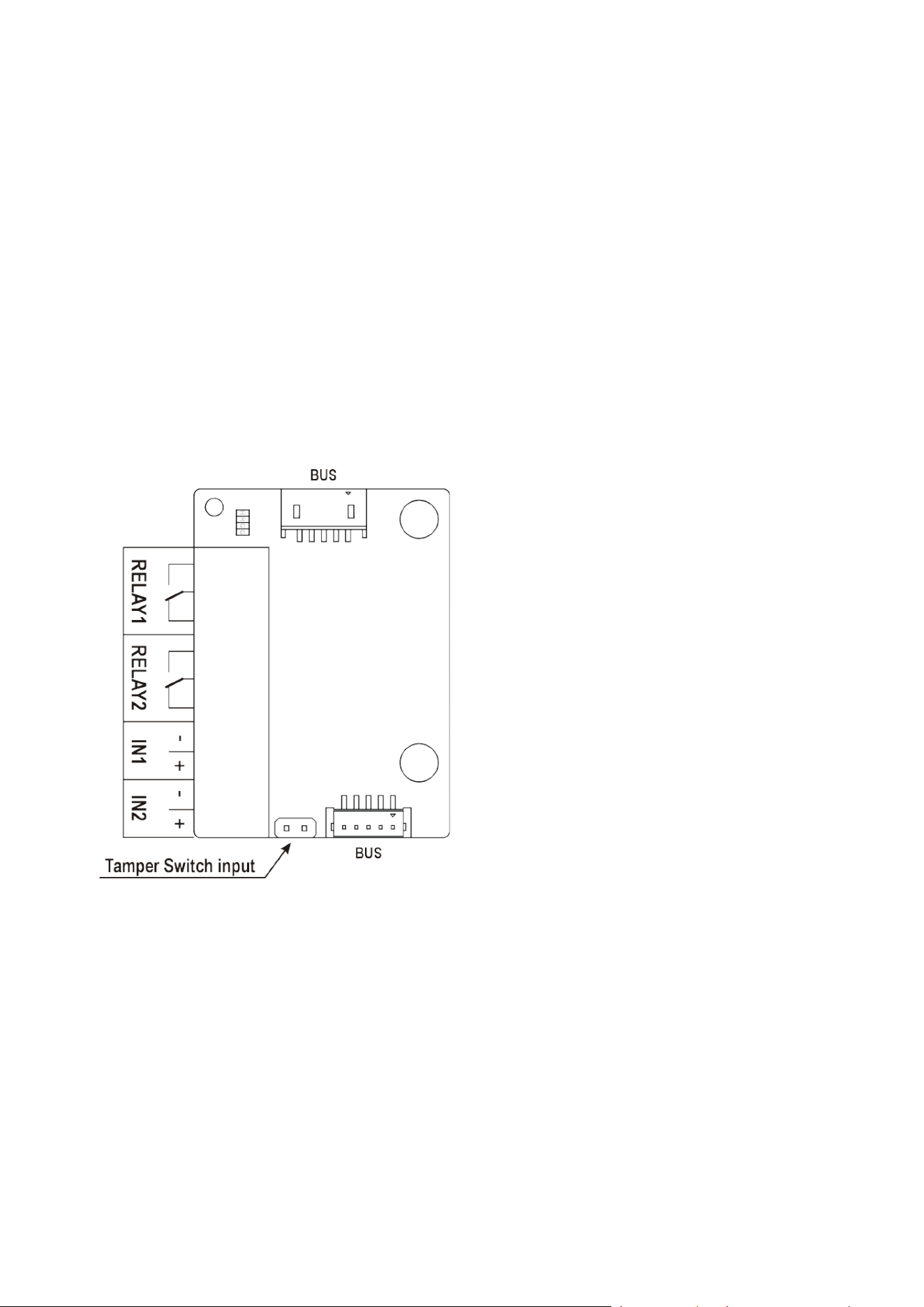
Installation manual 2N® IP Verso 2.0
166 / 213
•
•
•
•
•
I/O
The I/O module (Part No.9155034) is one of the2N
®
IP Verso 2.0 intercom elements and is used
for extending the number of inputs and outputs.
The module contains two2N
®
IP Verso 2.0bus connectors.
These two connectors are fully interchangeable and can be used both as inputs from the
main unit and outputs to other modules.
If this module is the last one on the bus, one of the connectors remains unconnected.
The module package includes an 80 mm long interconnecting cable.
The inputs / outputs are addressed as follows:<module_name>.<input/output_name>,
e.g. module5.relay1.The module name is configured in theModule name parameter in
theHardware / Extenders menu.

Installation manual 2N® IP Verso 2.0
167 / 213
•
•
•
•
•
•
•
•
RELAY1 RELAY1 terminals with accessible 30 V / 1 AAC/DC NO/NC contact
RELAY2 RELAY2 terminals with accessible 30 V / 1 A AC/DC NO/NC
contact
IN1 IN1 terminals for input in passive/ active mode (−30 V to +30 V
DC)
OFF = open OR U
IN
> 1.5 V
ON = closed contact OR U
IN
< 1.5 V
IN2 IN2 terminals for input in passive/active mode(−30 V to +30 V DC)
OFF = open OR U
IN
> 1.5 V
ON = closed contact OR U
IN
< 1.5 V
TAMPER Tamper switch (9155038) input
5-Button
The 5-button module (Part No.9155035)is one of the2N
®
IP Verso 2.0intercom elements and is
used for extending the number of buttons.
The module contains two2N
®
IP Verso 2.0 bus connectors.
These two connectors are fully interchangeable and can be used both as inputs from the
main unit and outputs to other modules.
If this module is the last one on the bus, one of the connectors remains unconnected.
The module package includes a 220 mm long interconnecting cable.
Nametag dimensions:
1 button: 52,0 (W) x 15.2 (H) mm (dimensional tolerance: +0; −0.5 mm).
5 buttons: 57.5 (W) x 89.0 (H) mm (dimensional tolerance: +0; −0.5 mm).
Refer towww.2n.comfor the nametag printing template.
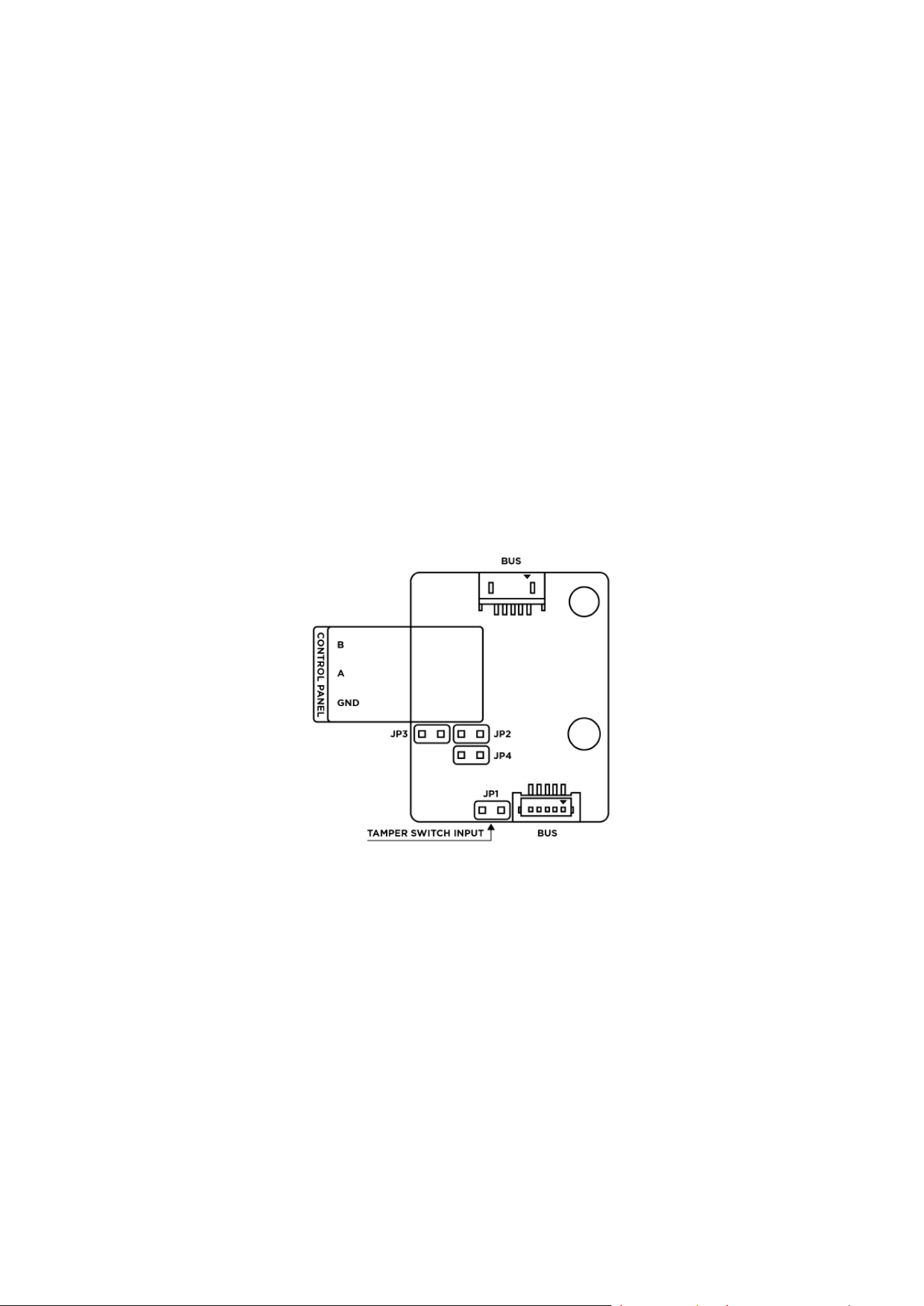
Installation manual 2N® IP Verso 2.0
168 / 213
•
•
•
•
•
•
•
OSDP
The OSDP module (Part No. 91550371) is one of the 2N
®
IP Verso 2.0 modules and provides
communication between a connected device (control panel, door controller) and 2N
®
IP Verso
2.0 via the OSDP. The OSDP module provides secure sending of such access data as the access
card ID or PIN code. All the inputs and outputs are galvanically isolated from the2N
®
IP Verso
2.0system with insulation strength of 500 V DC.
The module contains two VBUS connectors for device bus connection.
These two connectors are interchangeable and can be used either as inputs from the main
unit or outputs to other modules.
If this module is the last one on the bus, one of the connectors remains unconnected.
The module package includes a 80 mm long interconnecting cable.
The module also includes:
Isolated OSDP bus
Power and pairing mode signaling LED
Tamper switch (9155038) input
Installation Procedure
Having connected the OSDP module to 2N
®
IP Verso 2.0 via the VBUS, connect the OSDP device
to the module. The OSDP module uses the RS-485 bus for the interface.
Connect the OSDP device as instructed (A to B or B to A) keeping the correct order to avoid
malfunction.

Installation manual 2N® IP Verso 2.0
169 / 213
•
•
•
•
•
•
•
•
Having logged in to the 2N
®
IP Verso 2.0 web interface, use the HW / Extending Modules menu to
set the following:
Give the module a user identification (optional).
Choose a group for access data resending, making sure that the settings are identical with
those of the access readers from which the data are to be resent (card ID< PIN).
The settings of the codes to be transmitted are optional.
Enter the OSDP address between 0 and 126 to set the OSDP module address on the OSDP
line.
Set the communication rate in accordance with the requirements of the device to be
connected.
Enter your own encryption key into 2N
®
IP Verso 2.0 and the opponent’s device to ensure
encrypted communication.
Enable forced encryption just for encrypted communication.
Any unencrypted communication from the OSDP device will be rejected if forced encryption is
enabled.
If the OSDP device enables remote encryption key setting on a peripheral, you can use the
installation mode. Once the encryption key is received, the common mode is automatically
switched on. The installation mode is signaled by a LED fast blinking on the OSDP module.
Wiegand
The Wiegand module (Part No.9155037)is one of the2N
®
IP Verso 2.0intercom elements and
is used for connecting an external Wiegand device (RFID card reader, fingerprint or other
biometric data reader) and/or connecting the2N
®
IP Verso 2.0system to an external security
exchange. All the inputs and outputs are galvanically isolated from the2N
®
IP Verso 2.0system
with insulation strength of 500 V DC. It is necessary to feed +UINon Wiegand OUT from the
Control Panel.
Reader – connects an external Wiegand-supporting reader. The reader sends information
on the intercom card number.
•
•
Caution
When the JP2 and JP3 jumpers are mounted, strong pull-up / pull-down resistors
(560 ohm) are connected to the RS-485 bus. These jumpers must be mounted /
unmounted together, i.e. you cannot mount just one of them. The strong pull-up /
pull-down resistors can be connected only and exclusively to one arbitrary device
on the OSDP bus.
When the JP4 jumper is mounted, a 120 ohm termination resistor is placed
between the A and B wires of the OSDP bus. The termination resistors can be
connected exclusively to the first and last OSDP bus modules. We recommend that
these resistors are connected to the first and last modules.
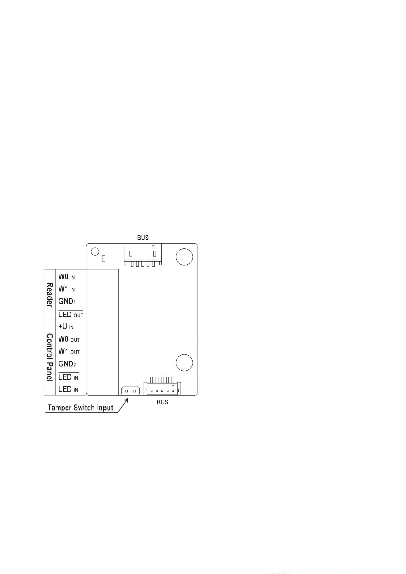
Installation manual 2N® IP Verso 2.0
170 / 213
•
•
•
•
•
•
•
•
•
Control Panel – used for connection to the security PBX or access system to which the
intercom sendsinformation on the intercom card number.
The module contains two2N
®
IP Verso 2.0 bus connectors.
These two connectors are fully interchangeable and can be used both as inputs from the
main unit and outputs to other modules.
If this module is the last one on the bus, one of the connectors remains unconnected.
The module package includes an 80 mm long interconnecting cable.
The module name is configured in theModule name parameter in theHardware /
Extenders menu.
The input LED IN is addressed as follows:<module_name>.<input1>, e.g.
module2.input1.
The input Tamper is addressed as follows:<module_name>.<tamper>, e.g.
module2.tamper.
The output LED OUT (negated) is addressed
asfollows:<module_name>.<output1>, e.g. module2.output1.

Installation manual 2N® IP Verso 2.0
171 / 213
Reader W0 IN, W1
IN, GND
1
Isolated 2-wire WIEGAND IN
LED OUT Isolated open LED OUT switched againstGND1 on WIEGAND IN
side (up to 24 V / 50 mA)
Control
Panel
+U IN +U
IN
(5 to 15 V DC) WIEGAND OUT power supply input
W0 OUT, W1
OUT, GND
2
Isolated 2-wire WIEGAND OUT
LED IN
(negated)
Isolated input for open LED IN, input activated by GND2
LED IN Isolated input for open LED IN, input activated by +U
G +U
IN
WIEGAND OUTactive supply LED indicator
TAMPER Tamper switch (Part No. 9155038) input
Wiegand Input Technical Parameters
Current 5 mA
Input resistance 680 Ohm
Pulse length 50 μs
Delay between pulses approx. 2 ms
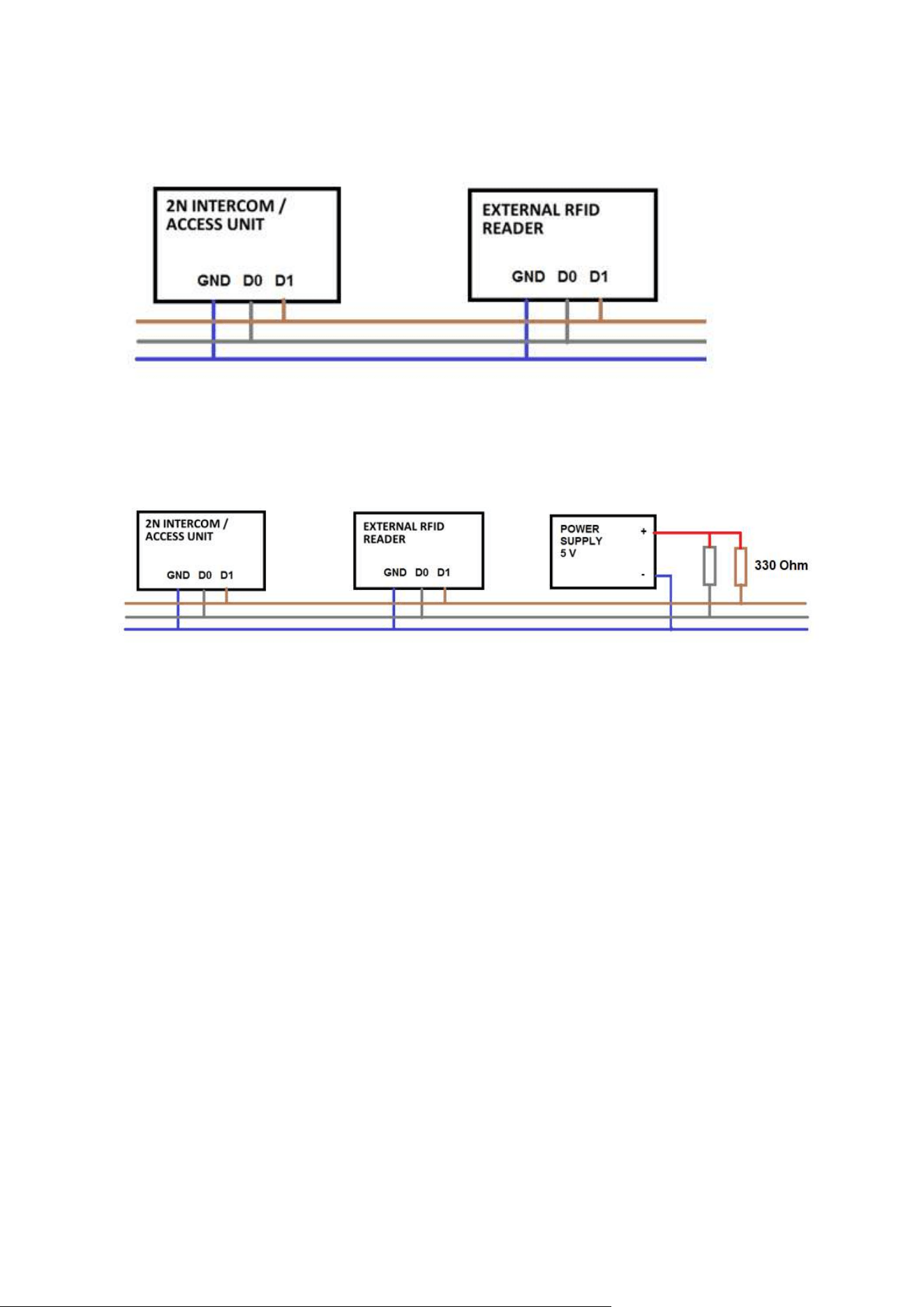
Installation manual 2N® IP Verso 2.0
172 / 213
•
•
•
•
Recommended Wiring Diagram for Reader with Bus Driver
Recommended Wiring Diagram for Reader with Open Collector (OC) Output
Tamper Switch
The Tamper switch (Part No.9155038)is one of the2N
®
IP Verso 2.0intercom elements and
helps secure the system against tampering.
The module contains two switches that open whenever the front frame is removed:
One switch leads directly to the terminal board and is designed for connection to an
external security exchange (32 V DC / 50 mA max).
The other switch, together with theI/O module (9155034)orWiegand module
(9155037), can be used for alarm signalling via the Automation interface in the2N
®
IP Verso 2.0configuration.
This module is not connected to the bus.

Installation manual 2N® IP Verso 2.0
173 / 213
Tamper Switch Mounting
Blind Panel
The Blind panel (Part No.9155039) is used to cover an empty position.
Security Relay
The2N
®
Security Relay(Part No.9159010) is used for enhancing security between the intercom
and the connected electric lock.The2N
®
Security Relayis designed for any2N IPintercom
model withfirmware versions 1.15 and higher. It significantly enhances security of the
connected electriclock as it prevents lock opening by forced intercom tampering.
•
Caution
Remember to purchase an I/O module, Part No. 9155034, together with the tamper
switch.

Installation manual 2N® IP Verso 2.0
174 / 213
•
•
•
Function:
The2N
®
Security Relayis a device installed between an intercom (outside the securedarea)
and the electric lock (inside the secured area). The2N
®
Security Relayincludesa relay that can
only be activated if the valid opening code is received from the intercom.
Specifications:
Passive switch: NO and NC contacts, up to 30 V / 1 A AC/DC
Switched output:
Where the security relay is fed from the intercom, 9 to 13 V DC is available on the output
depending on the power supply (PoE: 9 V; adapter: source voltage of minus 1 V) / 600 mA
DC.
Where the security relay is fed from an external power supply, 12 V / 700 mA DC is available
on the output.
Dimensions: (56 x 31 x 24) mm
Weight: 20 g
Installation:
Install the2N
®
Security Relayonto a two-wire cable between the intercom and theelectric lock
inside the area to be secured (typically behind the door). The device is poweredand controlled
via this two-wire cable and so can be added to an existing installation. Thanksto its compact
dimensions, the device can be installed into a standard mounting box.
Connection:
Connect the2N
®
Security Relayto the intercom as follows:
To the intercom active output (OUT1)
Connect the electric lock to the2N
®
Security Relayoutput as follows:

Installation manual 2N® IP Verso 2.0
175 / 213
•
•
To the switched output.
To the passive output in series with the external power supply.
The device also supports a Departure button connected between the ‘PB’ and ‘- Helios IP /
intercom’terminals. Press the Departure button to activate the output for 5 seconds.
Status signalling:
Green LED Red LED Status
flashing off Operational mode
on off Activated output
flashing flashing Programming mode – waiting for
initialisation
on flashing Error – wrong code received

Installation manual 2N® IP Verso 2.0
176 / 213
•
•
•
Configuration:
Connect the2N
®
Security Relayto the properly set intercom switch output; refer
totheConfiguration Manual for 2N IP intercoms. Make sure that one LED at least on
the2N
®
Security Relayis on or blinking.
Press and hold the2N
®
Security RelayReset button for 5 seconds to put the devicein the
programming mode (both the red and green LEDs are blinking).
Activate the intercom switch using the keypad, telephone, etc. The first code sent from
theintercom will be stored in the memory and considered valid. After code initialisation,
the2N
®
Security Relaywill pass into the operational mode (the green LED is blinking).
•
Caution
In case of resetting the factory default settings on a device with a version of
firmware 2.18 or higher it is necessary to reprogram the
2N
®
Security Relay using the instructions above.
•
Tip
FAQ: 2N
®
Security Relay – what is it and how to use it with 2N IP intercom?
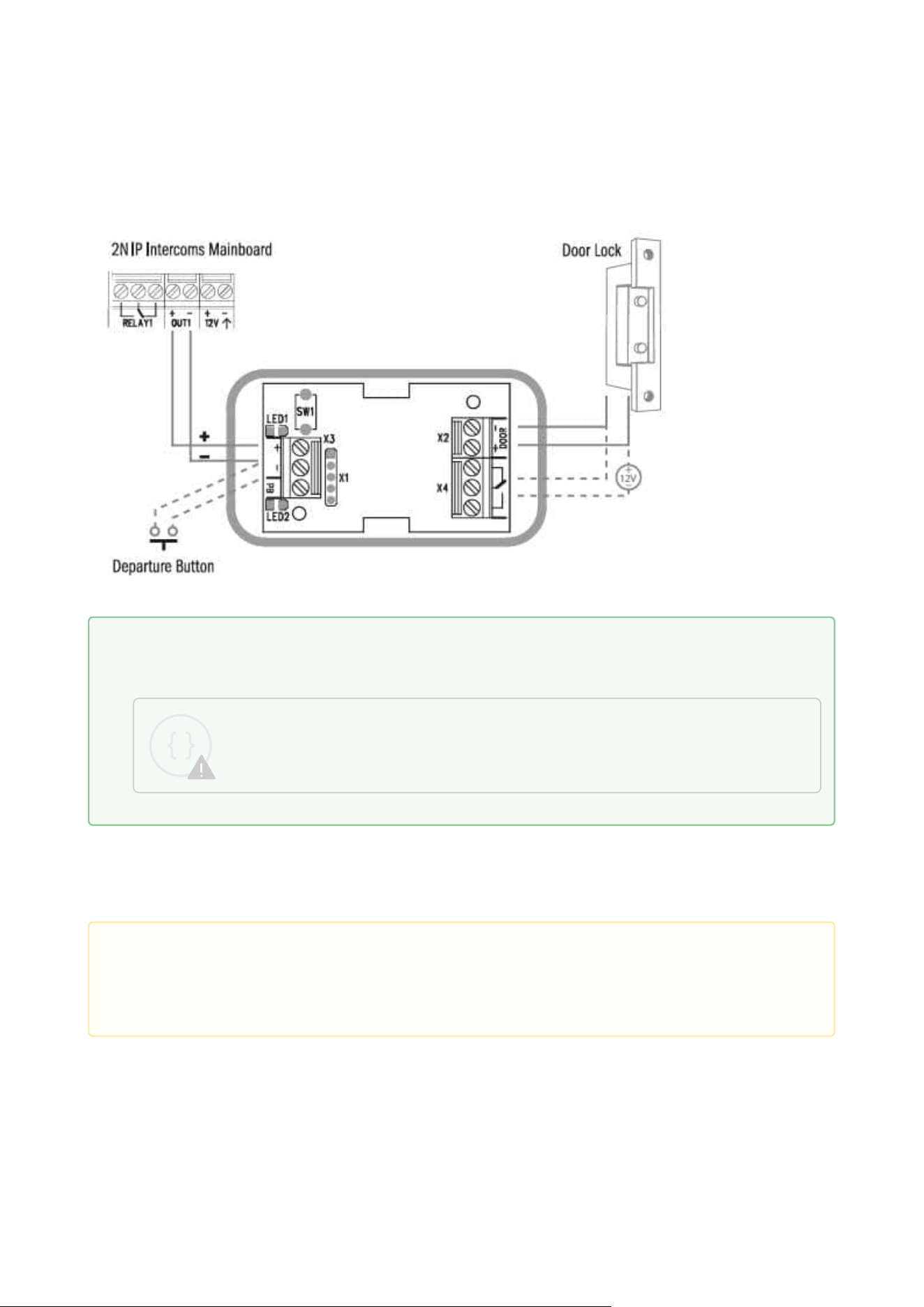
Installation manual 2N® IP Verso 2.0
177 / 213
Connection:
2.5 Completion
Check the connection of all wires and the RJ-45 plug to the board connector.
Make sure before mounting that the black sealing ring is placed properly. We recommend you to
fit the microphone with the screw included in the delivery.
Tip
Video Tutorial: Security Relay Installation and Configuration
Sorry, the widget is not supported in this export.
But you can reach it using the following URL:
https://www.youtube.com/watch?v=ardukvQzw5A
•
Caution
All unused connectors have to have tightened screws in order to avoid vibration
caused by sound.

Installation manual 2N® IP Verso 2.0
178 / 213
•
•
Nametag Placing
Every intercom package includes a piece of transparent foil, which can be laser printed. Cut the
printed foil and insert the nametags in the buttons.
We recommend you to use separate foil for every button in the 5-button module.Refer to
section downloadfor the nametag printing template.
Nametag dimensions for 5-button module:
1 button: 52.0 (W) x 15.2 (H) mm (dimensional tolerance: +0; -0.5 mm)
5 buttons: 57.5 (W) x 89.0 (H) mm (dimensional tolerance: +0; -0.5 mm)
Infopanel nametag dimensions: 69.2 (W) x 86.7 (H) mm (dimensional tolerance: +0; -0.5 mm).

Installation manual 2N® IP Verso 2.0
179 / 213
1.
2.
3.
4.
5.
•
•
Nametag inserting/replacing
Remove the frame.
Lift up the button door. The 5-button module buttons have just one door.
Remove the used nametag and insert a new one.
Close the button door.
Replace the frame.
Frame Replacement
Check the frame sealing before replacing the frame.
Version A
Screw the flush mounting frame in the upper and bottom parts.
Version B
Hang the surface mounting frame on the hook in the upper part and then screw it tight in
the bottom part.
Most Frequent Mounting Errors
At first, mount the metal bolts, level the bases on an even surface and tighten the screws.
•
•
Caution
The area where nametags are placed is called a wet zone. After heavy rain, water
can penetrate to the nametag. Water in this area does not affect the intercom
functionality in any way and evaporates soon.
Always use waterproof foil (enclosed or other) for the nametags. Never use paper
or ink jet printing to avoid damage due to water leakage!
•
•
•
Caution
Improper mounting may deteriorate the intercom waterproofness and water may
damage the electronic part.
Make sure that all holes are filled with some waterproof material– the top part,
around the cables and the screws.
Use silicone or some other sealant to seal the box against the wall if uneven to
avoid water leakage and wall damping.
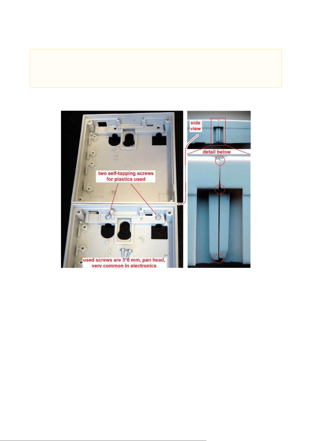
Installation manual 2N® IP Verso 2.0
180 / 213
The examples in the figures below show incorrectly assembled bases. This happens, in
particular, where the screws are tightened first.
•
Caution
Make sure that the bases are levelled properly to avoid water leakage and
electronic damage.
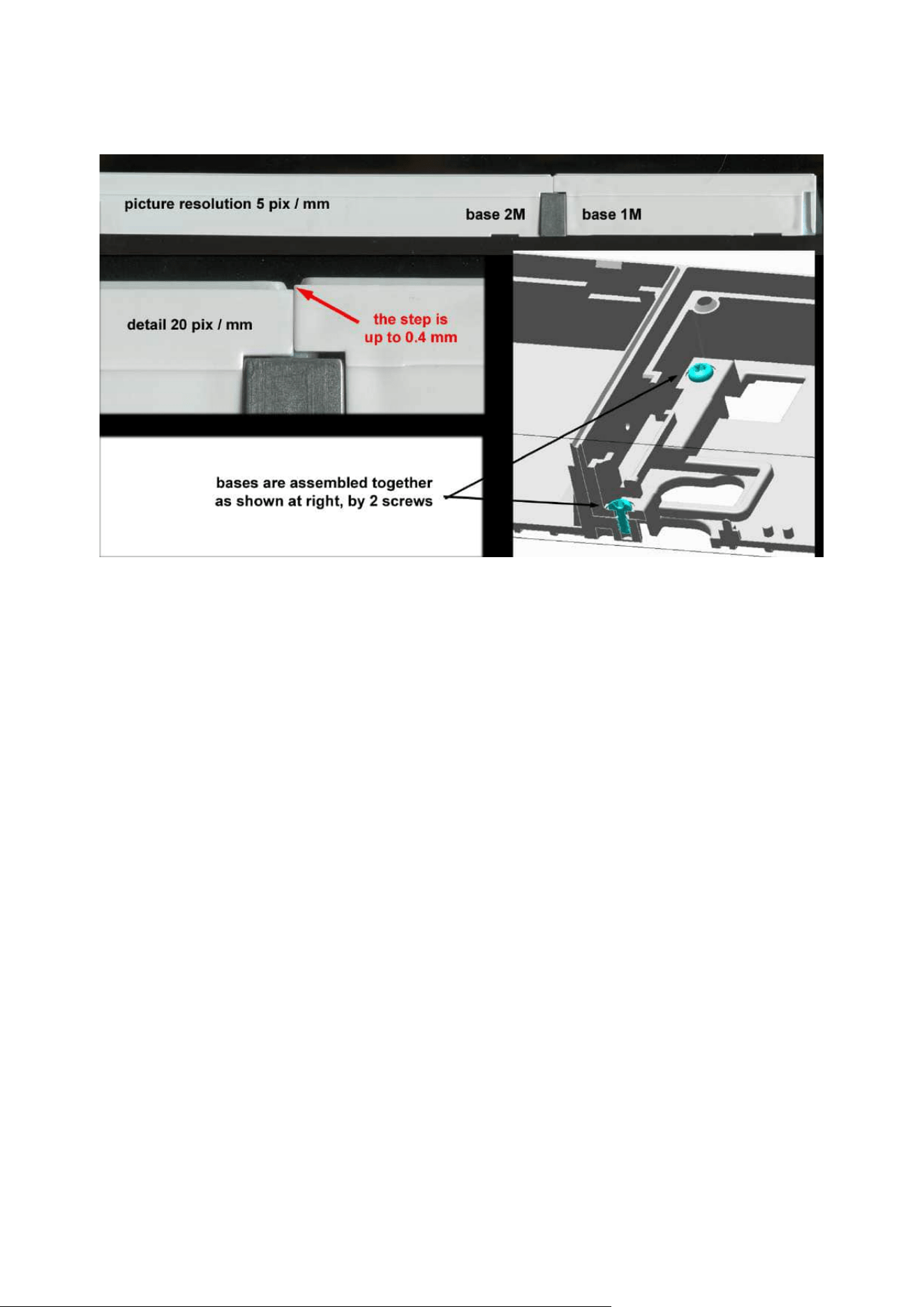
Installation manual 2N® IP Verso 2.0
181 / 213

Installation manual 2N® IP Verso 2.0
182 / 213
•
•
•
•
•
•
•
•
•
3. Function and Use
This section describes the basic and extending functions of thethe2N
®
IP Verso 2.0 product.
3.1 Configuration
3.2 Intercom Control as Viewed by External User
3.3 Touch Display Intercom Control As Viewed by External User
3.4 Intercom Control as Viewed by Internal User
3.5 Maintenance
3.6 Downloads
3.1 Configuration
Configure2N
®
IP Verso 2.0 using yourPC with anyinternet browser:
Launch your internet browser (Chrome, Firefox, etc.).
Enter the IP address of your intercom (http://192.168.1.100/, e.g.).
Log in using the usernameAdminand password2n.
You have to know your intercom IP address to log in to the integrated web server. Upon
purchase,2N
®
IP Verso 2.0is set to the dynamic IP address mode – it retrieves the IP address
automatically if there is a properly configured DHCP server in the LAN. If no DHCP is available,
operate2N
®
IP Verso 2.0 in the static IP address mode. Refer to the Configuration Manualfor
the2N
®
IP Verso 2.0configuration details.
If your device remains inaccessible (you have forgotten the IP address, the network
configuration has changed, etc.), you can change the network configuration using the device
buttons.
IP Address Retrieval
Press the Speed dial button 5 times to retrieve the IP address.
Static IP Address Setting
Press the Speed dial button 15 times to set the device network to the static IP address(DHCP
OFF) mode.

Installation manual 2N® IP Verso 2.0
183 / 213
•
•
•
•
•
Dynamic IP Address Setting
Press the Speed dial button 15 times to configure the device network with the dynamic IP
address(DCHP ON).
Factory Reset
Located among the main unit connectors, the CONTROL button helps you reset the factory
default values.
Follow the instructions below to reset the factory default values:
Disconnect the device from the power supply.
Press and hold the CONTROL button.
Connect the device to the power supply.
Keep holding the button for a few seconds and then release it.

Installation manual 2N® IP Verso 2.0
184 / 213
1.
2.
Device Restart
To restart the device, disconnect the device from the power supply or use the web interface in
the System / Maintenance section.No configuration change appearsafter the restart.
Firmware Upload
We also recommend you to update your intercom firmware upon the first login to the
intercom.Use the device web interface in the System > Maintenance > System configuration
section for firmware upgrade(seeConfiguration manual for 2N IP intercoms). Refer
to2N.comfor the latest firmware version. The device restarts automatically after the upgrade is
completed successfully. The whole process takes almost one minute.
3.1.1 2N® IP Verso LAN Location via 2N® Network Scanner
2N
®
IP Versois configured via the administration web server. Connect the device to the LAN IP
and make sure it is properly powered.
2N
®
Network Scanner Description
The application helps find the IP addresses of the 2N devices in the LAN. Download the app from
the 2N web sites (www.2n.com). Make sure that Microsoft .NET Framework 2.0 is installed for
successful app installation.
Run the2N
®
Network Scannerinstaller.
Use the Setup Wizard for successful installation.
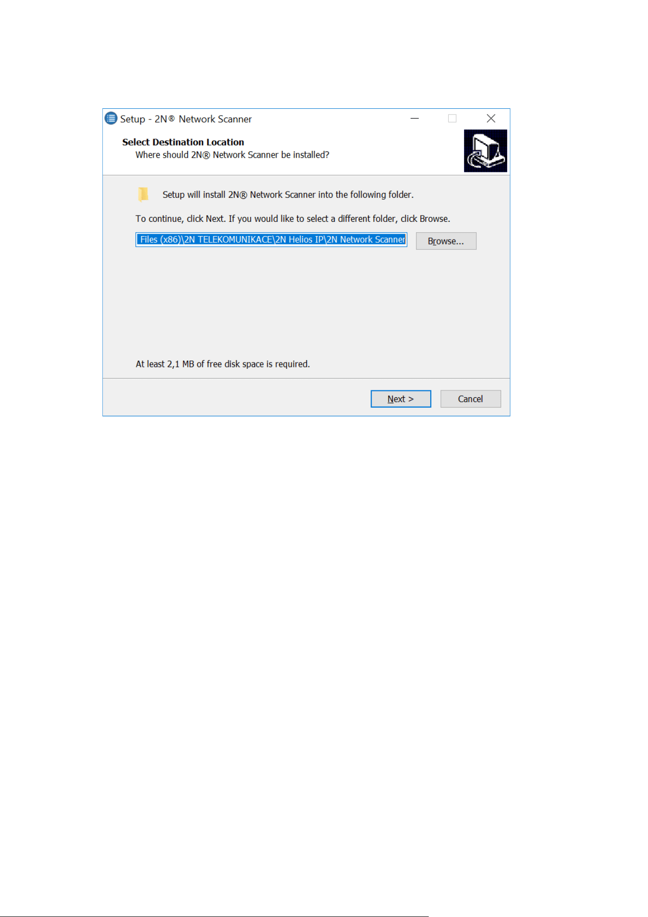
Installation manual 2N® IP Verso 2.0
185 / 213
3.
Setup Wizard of 2N
®
Network Scanner
Having installed2N
®
Network Scanner, start the application using the Microsoft Windows
Start menu.
Once started, the application begins to automatically search for all the 2N devicesin the
LAN including their smart extensions which are DHCP/statically assigned IP addresses. All
the devices are then displayed in a table
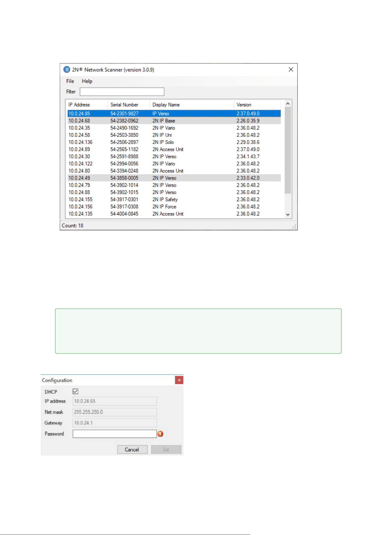
Installation manual 2N® IP Verso 2.0
186 / 213
4.
Window of 2N
®
Network Scanner
Select the2N
®
IP Versodevice to be configured and right-click it. SelectBrowse...to open
the2N
®
IP Versoadministration web interface login window for configuration. To change
the device IP address, selectConfigand enter the required static IP address or activate
DHCP. The default configuration password is: 2n. If the found device is grey highlighted, its
IP address cannot be configured using this application. In that case, click Refresh to find
the device again and check whether multicast is enabled in your network.
•
Tip
Double click the selected row in the 2N
®
Network Scanner list to access the
device web interface easily.

Installation manual 2N® IP Verso 2.0
187 / 213
•
•
•
2N
®
Network Scanner IP Address Change
3.2 Intercom Control as Viewed by External User
Quick Dial Buttons
Press the quick dial button on the main unit to dial the first position in the phone directory
(Phone Book) depending on the model type. Use extending modules to extend the number of
quick dial buttons to up to 146.
By pressing the quick dial buttons you dial the phone numbers assigned to the particular Phone
Book position. Call setup is signalled by a long intermittent or any other tone depending on the
configuration of the PBX connected.
Repeated pressing of one and the same quick dial button during call setup may initiate call
hangup or call termination plus dialling the next phone number of the called subscriber, or may
be assigned no function; refer to theIntercom Configuration / Hardware / Keypadsubsection of
Configuration Manual.
You can also press the button anytime to hang up if enabled so in theButton Function
During Callparameter; refer to theIntercom Configuration / Hardware / Keypadsubsection of
Configuration Manual.
Calling to Phone Book Position
The 2N
®
IP Verso 2.0 Phone Book can contain up to 10 000 programmable positions. The quick
dial buttons can only be used for positions 1 through 146, depending on the number of actually
installed buttons. You can dial the other positions using the numeric keypad if theDial by
Numeric Keypadfunction is enabled; refer to theIntercom Configuration / Hardware /
Keypadsubsection of Configuration Manual.
Procedure:
Enter the position number using the numeric keypad (05, 15, 200, e.g. – two digits at
least and four digits at most) and press the button for confirmation.
You can also press the button anytime to hang up if enabled so in theButton
Function During Callparameter; refer to theIntercom Configuration / Hardware /
Keypadsubsection of Configuration Manual.

Installation manual 2N® IP Verso 2.0
188 / 213
•
a.
b.
c.
d.
•
•
•
•
Calling to User-Defined Phone Number
If theTelephone function enabled(refer to theIntercom Configuration / Hardware /
Keypadsubsection of Configuration Manual) parameter is selected, you can dial a user-
defined phone number using the2N
®
IP Verso 2.0numeric keypad.
Procedure:
Press .
You will hear a continuous tone from the speaker.
Enter the phone number via the numeric keypad and press again to confirm
your dialling.
You can also press the button anytime to hang up if enabled so in theButton
Function During Callparameter; refer to theIntercom Configuration / Hardware /
Keypadsubsection of Configuration Manual.
Incoming Call Answering/Rejecting
If the automatic incoming call answering function is disabled (refer totheIntercom
Configuration / Services / Phone / Calls subsection of Configuration Manual), the incoming
call to2N
®
IP Verso 2.0is signalled with loud ringing. Press to answer the call and
to reject the call.
Door Opening (Switch Activation) by Code
2N
®
IP Verso 2.0is equipped with a door unlocking switch. Enter the valid code (refer to
theIntercom Configuration / Hardware / Switches subsection of Configuration Manual)
using the numeric keypad to activate this switch.
Procedure:
Enter the switch activating numerical code using the numeric keypad and press
for confirmation.
A valid code is notified visually and by a continuous switch activation tone or a
predefined unlocking user sound. An invalid codeor interruption longer than as
defined in Timeout for Entering Numbersis signalled by the sound or a user
sound.
Door Opening (Switch Activation) by Biometric Reader
A biometric reader helps authenticate human fingerprints for control and management of
access and third party devices. Refer to Directory / Users for how to load a fingerprint into
a user profile.
Procedure:
Apply your finger to the reader scanning area.
Reader authentication light signalling:

Installation manual 2N® IP Verso 2.0
189 / 213
•
•
•
Green – the fingerprint has been recognised successfully.
Green flashes to red – the fingerprint has been recognised but access is
denied. Check the user time profile setting state and multiple
authentication setting. Access can also be blocked by a previous tamper
switch blocking.
Red – the fingerprint has not been recognised.
3.3 Touch Display Intercom Control As Viewed by External User
The2N
®
IP Verso 2.0model can be equipped with a colour LCD display, which displays the
device states (call progress, door opening, etc.) and can work in several modes. Until the display
configuration is loaded,2N
®
IP Verso 2.0displays no users to be called in theDirectory menu. If
configured properly, the2N
®
IP Verso 2.0 starts displaying an Ad menu or the Directory/Keypad
introductory menu or separate Directory or Keypad menus. Control a display-equipped2N
®
IP
Verso 2.0 intercom by touching the display and browsing.
Presentation
In the Presentation mode, one or more images defined by the available display configuration are
displayed. The Presentation mode is started automatically when the presentation delay timeout
set in the 2N®IP Versoweb interface expires. The mode can be terminated by a touch of the
icon, which moves2N
®
IP Verso 2.0into the display introductory menu, or by an incoming
call to2N
®
IP Verso 2.0.
•
Note
A higher moisture may deteriorate finger papillary line scanning. You are advised
to dry your finger and the reader scanning surface for successful authentication.
Installation manual 2N® IP Verso 2.0
190 / 213
Contacts
In the Contacts mode, a structured list of usersdefined by the available display configuration is
displayed. The user list can be divided into a practically arbitrary count of groups. Browse
through the Directory by touching the display. Click to return to the superior group or the
display introductory menu. Touch the user name to make a call in the Contacts mode.
This mode helps you quick search contacts too. Touch the witch the
Contacts into the search mode and enter the string to be searched via the touchpad. See the
string in the status line in the upper part of the display. Touch the
See the count of found users in the right-hand upper corner of the display. Touch the found
contacts and browse through the data.
The Contacts menu also includes a Help submenu in the right-hand bottom corner of the
display, which provides tips and basic display controls for the Contacts mode.
display icon to s
display icon to delete the currently last character of the text to be searched. The string is
searched for in the current group and subgroup levels.

Installation manual 2N® IP Verso 2.0
191 / 213
Call
Use the Call mode to make calls to the intercom Directory users.
If you set User position number or User virtual number, just enter the number and click
to get back to the display introductory
menu.
To call a user, set Dialling via keypad in the intercom web interface and select one of the
following options: Disabled, User position number or User virtual number.
for confirmation. Click

Installation manual 2N® IP Verso 2.0
192 / 213
Entry
The Entry mode helps you enter the switch codes. Enter the switch digital code and click
for confirmation. You can also enable Scramble keypad in the Keypad
mode via the web interface to scramble the numerical keypad buttons before every new display
in order to prevent third persons from seeing the code to be entered.
3.4 Intercom Control as Viewed by Internal User
Call Answering
You can answer the incoming calls to the2N
®
IP Verso 2.0 intercom using your phone like any
other calls. You can unlock the door, activate/deactivate a user/profile via your phone keypad
during the call. The calls, however, are time-limited to avoid unintentional blocking of the2N
®
IP
Verso 2.0line. Set the maximum call duration in theCall time limit(refer tothe Intercom
Configuration / Services / Phone / Calls subsection of Configuration Manual). Press # on your
phone anytime to extend the call time. The automatic call termination is signalled with a short
beep 10 s before the call end.
Calling to 2N
®
IP Verso
2N
®
IP Verso 2.0allows you to answer incoming calls. Set the required parameters in the
Incoming calls group;refer totheIntercom Configuration / Services / Phone / Calls subsection of
Configuration Manual.

Installation manual 2N® IP Verso 2.0
193 / 213
•
•
•
•
Door Opening (Switch Activation) by Code
2N
®
IP Verso 2.0is equipped with a door unlocking switch. Enter the valid code (refer
totheIntercom Configuration / Hardware / Switches subsection of Configuration Manual) using
your phone keypad to activate this switch.
Procedure:
Enter the switch 1 or 2 activating code using your phone keypad and press for
confirmation. Confirmation is unnecessary if theLock code without confirmationis
enabled,refer to theIntercom Configuration / Hardware / Switches / Advanced
subsection of Configuration Manual.
A valid code is signalled by the sound. An invalid codeor interruption longer than as
defined inTimeout for Entering Numbersis signalled by the sound.
Profile Activation/Deactivation
Activate/deactivate a profile using your phone in order to route calls directly to the phone
numbers tied with the profile, refer totheIntercom Configuration / Directory / Time Profiles
subsection of Configuration Manualfor details.
Procedure:
Enter the profile activating/deactivating code using your phone keypad and press for
confirmation.
A valid code is signalled by the or sound according to the code type. An invalid
codeor interruption longer than as defined inTimeout for Entering Numbersis signalled
by the sound.
3.5 Maintenance
If used frequenly, the device surface, the keypad in particular, gets dirty.To clean it, use a piece
of soft cloth moistened with clean water.

Installation manual 2N® IP Verso 2.0
194 / 213
3.6 Downloads
Templates
Nameplates
Infopanel label
Software
2N
®
USB driver
2N
®
IP Eye
2N
®
Network Scanner
•
Anticovid
To keep your equipment surfaces clear of bacteria and viruses (Anti-Covid
disinfection) and maintain the hygienic conditions of critical surfaces and touch
points we recommend that you use the Zoono – Microbe Shield Surface Sanitiser
Spray.
•
•
•
Caution
Always use the product for the purpose it was designed and manufactured for, in
compliance herewith.
The manufacturer reserves the right to modify the product in order to improve its
qualities.
2N
®
IP Verso 2.0contains no environmentally harmful components. When the
product's service life is exhausted and you would like to dispose of it please do so
in accordance with applicable legal regulations.

Installation manual 2N® IP Verso 2.0
195 / 213
•
•
•
•
•
•
•
•
•
•
•
•
•
•
•
4. Technical Parameters
Signalling protocol
SIP (UDP, TCP, TLS)
Buttons
Button design:white-backlit transparent buttons with replaceable nametags
Button count:1 and increments of 5
Button extenders:up to 29 modules, limited by power supply
Numeric keypad:optional
Audio
Microphone:1 integrated microphone
Amplifier: 5 W (class D) amplifier
Speaker: 2 W / 8 Ω
Sound pressure level(SPL max): 78 dB (for 1 kHz, distance 1 m)
Output LINE OUT:1 VRMS / 600Ω
Volume control:adjustable with automatic adaptive mode
Full duplex:yes (AEC)
Audio output: 1.9 W
Audio stream
Protocols: RTP/SRTP
Codecs: G.711, G.729, G.722, L16/16kHz

Installation manual 2N® IP Verso 2.0
196 / 213
•
•
•
•
•
•
•
•
•
•
•
Camera
Sensor: 1/2.7'' colour CMOS
JPEG resolution: up to 1920 (H) x 1440 (V)
Video resolution: 1920 (H) x 1440 (V)
Frame rate: up to 30 fps
Sensor sensitivity: 14000 e-/lux-sec
Infrared light:yes
Focal length: 1.9 mm
Video
Protocols: RTP/RTSP/RTCP/HTTP
Video call codecs: H.264
ONVIF/RTSP stream codecs: H.264, H.265, MJPEG
IP camera function: yes, ONVIF v2.4 profile S and ONVIF Profile T compatible

Installation manual 2N® IP Verso 2.0
197 / 213
•
•
•
•
•
•
•
•
•
•
•
•
•
Bandwidth
Audio codecs
PCMA, PCMU – 64 kbps (with 85.6 kbps headers)
G.729 – 16 kbps (with 29.6 kbps headers)
G.722 – 64 kbps (with 85.6 kbps headers)
L16 / 16 kHz – 256 kbps (with 277.6 kbps headers)
Video codecs
Set the video codec data flows in the Services / Phone / Video menu for calls and in the
Services / Streaming / RTSP menu for streaming. The set bit rate represents the value to
which the codec should get close on a long-term average. The data flows can vary
depending on the scene to be scanned.
Interface
Power supply: LPS/PS2 rated, 12 V ±15 % / 2 A DC or PoE (3 A if multiple modules are
used)
PoE: PoE 802.3af (Class 0–12.95 W)
LAN:10/100BASE-TX s Auto-MDIX, RJ-45
Recommended cabling: Cat-5e or higher
Supported protocols: SIP2.0, DHCP opt. 66, SMTP, 802.1x, RTSP, RTP, TFTP, HTTP,
HTTPS, Syslog, ONVIF
Passive switch: NO/NC contact, up to 30 V / 1 A AC/DC
Active switch output: 8 up to 12 V DCdepending on power supply (PoE: 10 V; adaptor:
power supply voltage minus 2 V), up to 400 mA

Installation manual 2N® IP Verso 2.0
198 / 213
•
•
•
•
•
•
•
•
•
•
•
•
•
•
•
•
•
•
•
•
•
•
•
•
•
•
•
•
•
•
•
•
•
•
•
RFID card reader
Optionally 125 kHz or 13.56 MHz
Supported cards, 125 kHz, Part No.9155032:
EM4xxx
Supported cards on 13.56 MHz NFC version, Part No. 9155040(only card serial number
is read)
ISO14443A (MIFARE DESFire)
PicoPass (HID iClass)
FeliCa
ST SR(IX)
2N
®
Mobile Key
Supported cards on secured 13.56 MHz NFC version, Part No. 9155086(optionally, card
serial number or PAC ID is read)
ISO14443A (MIFARE DESFire)
PicoPass (HID iClass)
FeliCa
ST SR(IX)
2N
®
Mobile Key
HID SE (Seos, iClass SE, MIFARE SE)
Maximum H – field strength at 10 m for 125 kHz version: 66 dBµA/m
Maximum H – field strength at 10 m for 13.56 MHz version: 60 dBµA/m
2N
®
IP Verso – Bluetooth module
Bluetooth 4.0 Compliant (Bluetooth Low Energy, BLE)
Security: asymmetric RSA-1024 and symmetric AES-128 encryption
RX sensitivity: up to−93 dBm
Range: adjustable (short ~ 0.5m, medium ~ 2m, long ~ up to 10m)
Power consumption: 20mA at 12V DC
Operational temperature range:−40°C ~ +60°C
Storage temperature range:−40°C ~ +70°C
Dimensions: 97x105x30mm
Compatible with 2N
®
IP Verso, 2N
®
LTE Verso and 2N
®
Access Unit
Mobile app. support:Android 6 and higher, iOS 12 and higher
Touch display
Resolution:320 px x 214 px H x V
Resolution slideshow:214 px x 214 px
Contrast ratio:400
Brightness:350 cd/m2
Viewing angle:80 ° from any direction
Weight:280 g
Consumption min:1.36 W

Installation manual 2N® IP Verso 2.0
199 / 213
•
•
•
•
•
Consumption max:2.40 W
Working temperature:−20 °C – 60 °C
Resistance level:IK07
I/O module
Dimensions: 43 (W) x 31.5 (H) x 1.5 (D) mm
Wiegand module
Dimensions: 43 (W) x 31.5 (H) x 1.5 (D) mm

Installation manual 2N® IP Verso 2.0
200 / 213
•
•
•
•
•
•
•
•
•
•
•
•
•
•
•
•
•
•
•
•
•
•
•
•
•
•
•
•
Mechanical properties
Cover:robust zinc casting with surface finish(minor surface shade nuances are
acceptable)
91550XX – NICKEL
Material– Zamak 410– Zn95Al4Cu1
Surface treatment– Zn/Cu20/Ni25b max. 80 µm
91550XXB– BLACK
Material– Zamak 410– Zn95Al4Cu1
Surface treatment–PUR Wet coating 15-25 µm, RAL 9005 Jet black
interior side - passivated zinc
Working temperature:−40 °C – 60 °C
Working relative humidity:10 % – 95 % (non-condensing)
Storing temperature:−40 °C – 70 °C
Dimensions
Surface mounting frame:
1 module: 107 (W) x 130 (H) x 28(D)mm
2 modules: 107 (W) x 234 (H) x 28(D)mm
3 modules: 107 (W) x 339 (H) x 28(D)mm
Flush mounting frame:
1 module: 130 (W) x 153 (H) x 5(D)mm
2 modules: 130 (W) x 257 (H) x 5(D)mm
3 modules: 130 (W) x 361 (H) x 5(D)mm
Flush mounting box (minimum hole dimensions):
1 module: 108 (W) x 131 (H) x 45 (D) mm
2 modules: 108 (W) x 238 (H) x 45 (D) mm
3 modules: 108 (W) x 343 (H) x 45 (D) mm
Module internal cutout:72 (W) x 89.3 (H) mm / 2.83 (W) x 3.51 (H) inches
Weight:max net weight: 2 kg / max gross weight: 2.5 kg – based on configuration
Covering level:IP54
Resistance level:IK08
4.1 General drawings
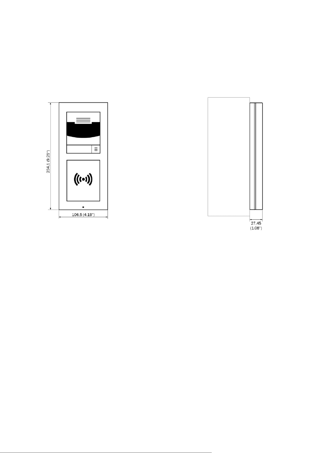
Installation manual 2N® IP Verso 2.0
201 / 213
Surface mounting
2 modules
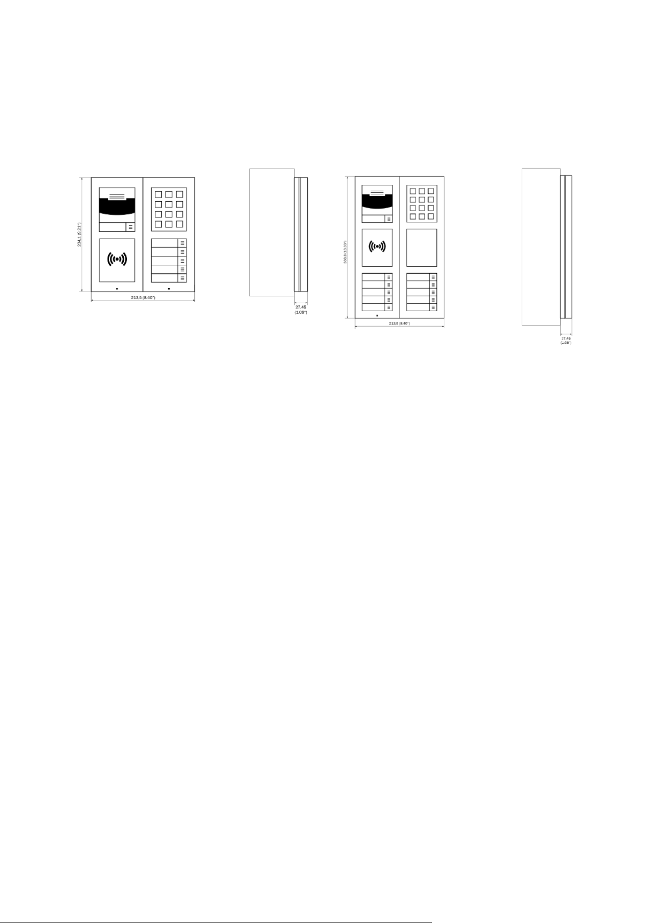
Installation manual 2N® IP Verso 2.0
202 / 213
2 x 2 modules 3 x 2 modules
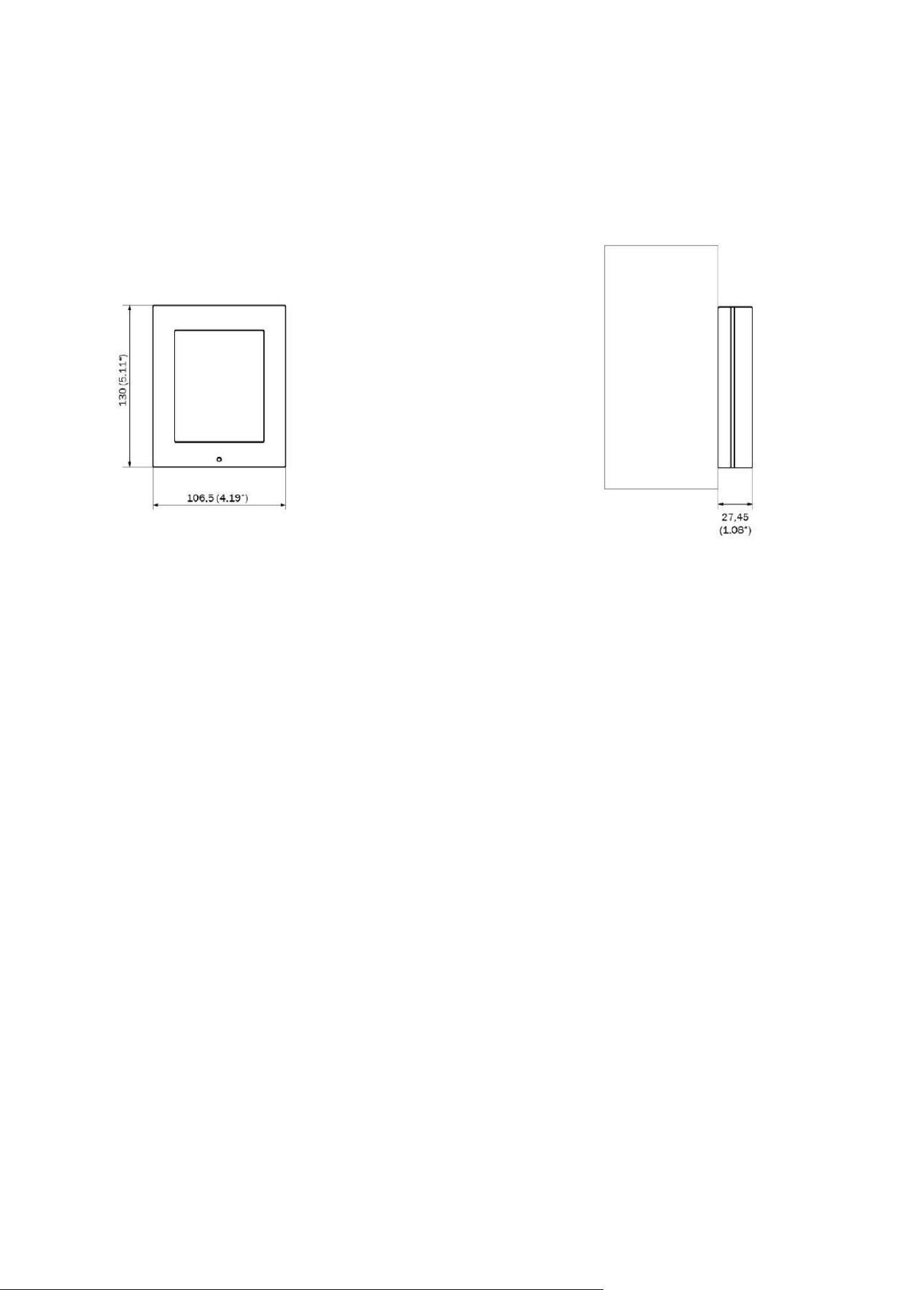
Installation manual 2N® IP Verso 2.0
203 / 213
1 module
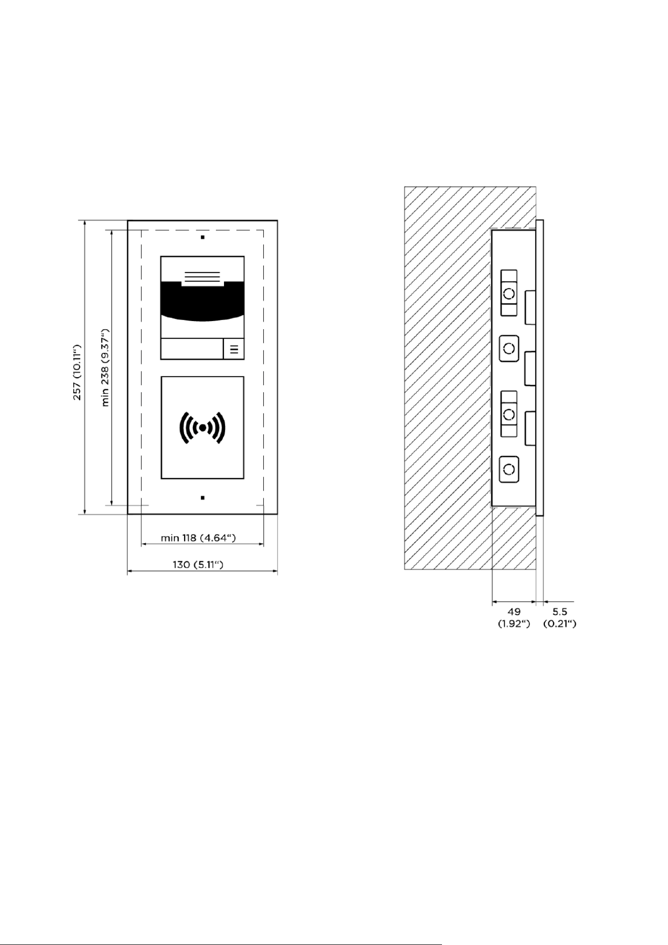
Installation manual 2N® IP Verso 2.0
204 / 213
Flush mounting
2 moduly
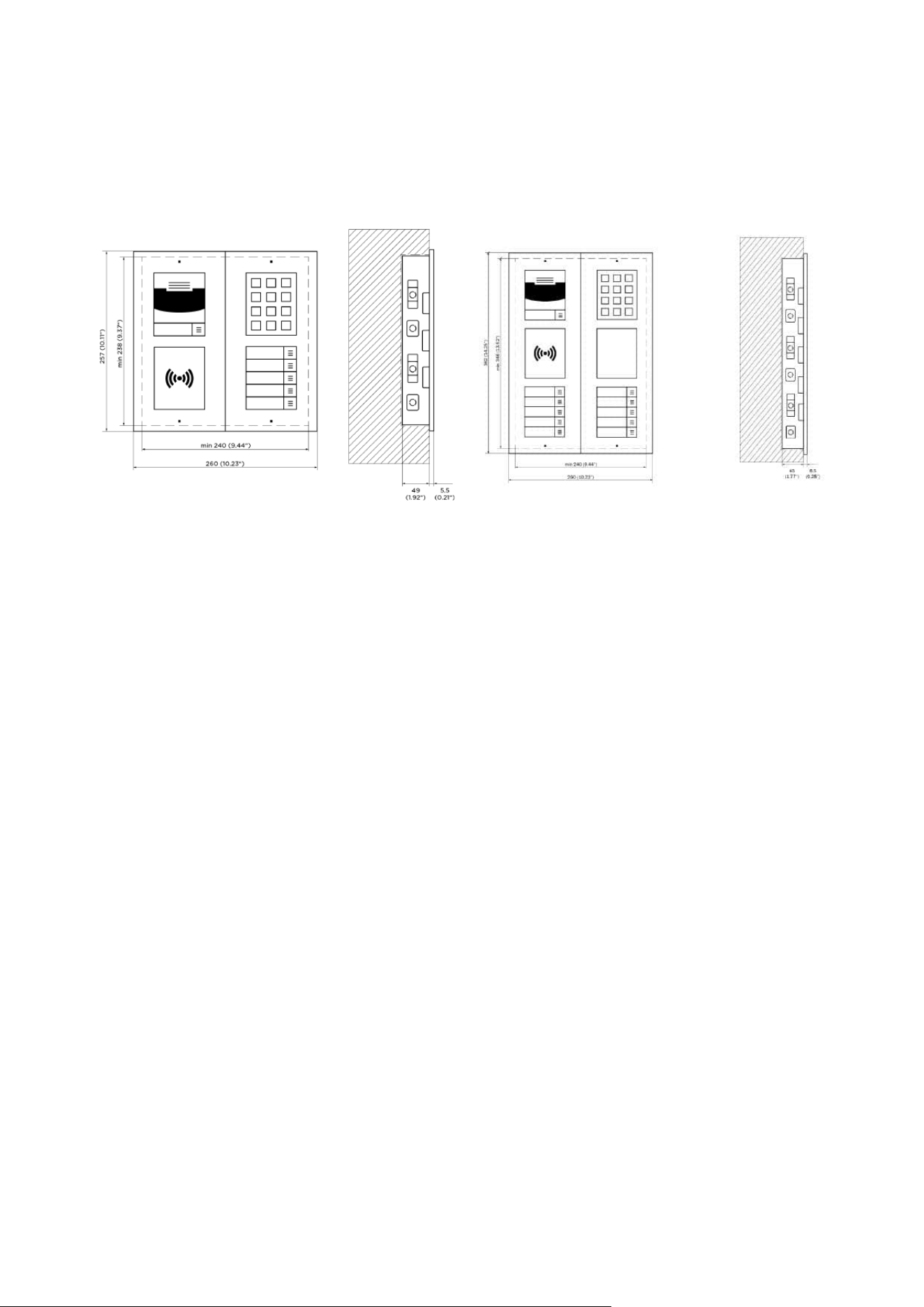
Installation manual 2N® IP Verso 2.0
205 / 213
2 x 2 modules 3 x 2 modules
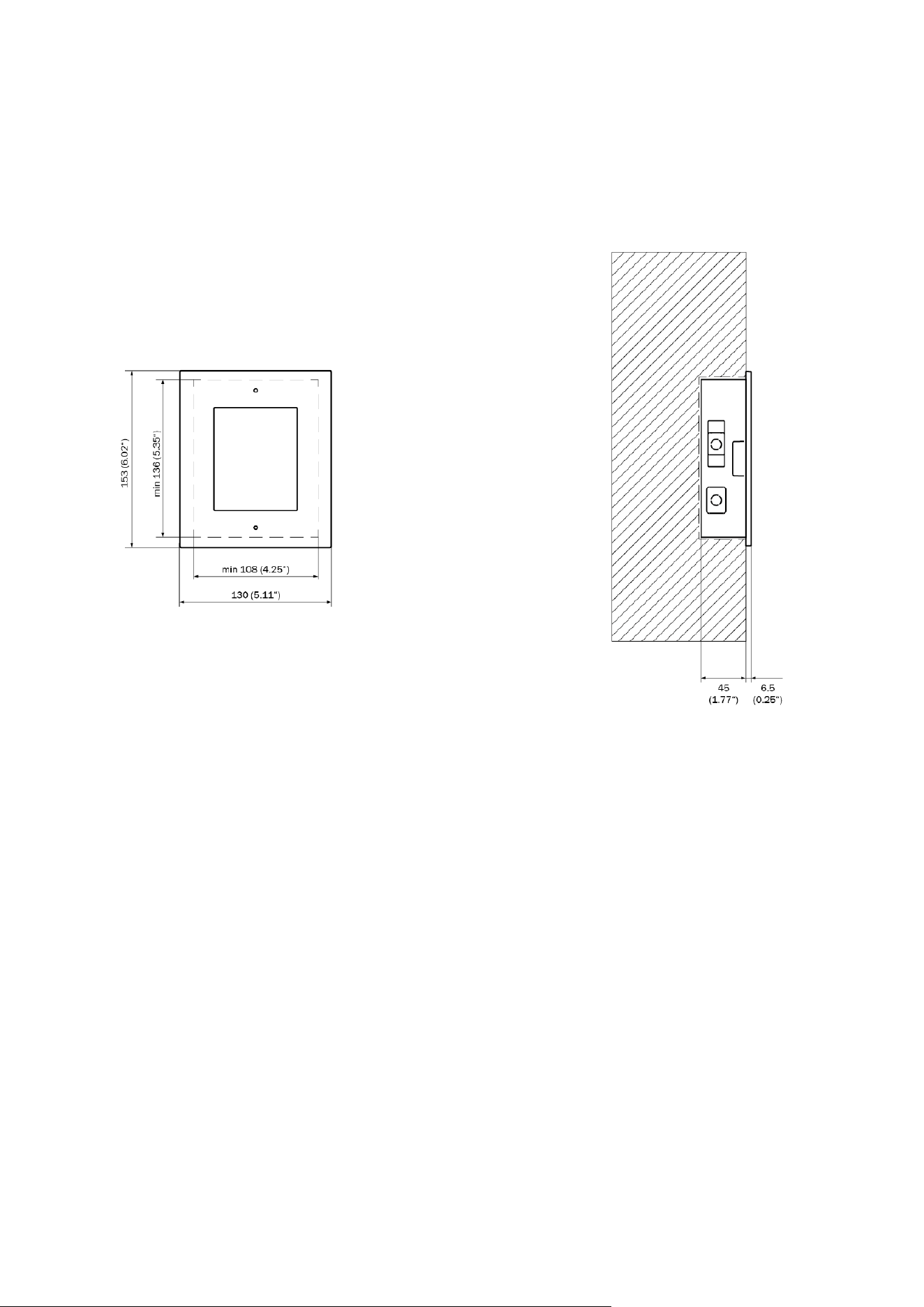
Installation manual 2N® IP Verso 2.0
206 / 213
1 module

Installation manual 2N® IP Verso 2.0
207 / 213
•
•
•
•
•
•
•
•
•
•
•
5. Supplementary Information
Here is what you can find in this section:
5.1 Troubleshooting
5.2 Directives, Laws and Regulations
5.3 Other Countries' Legislation
5.4 General Instructions and Cautions
5.1 Troubleshooting
For the most frequently asked questions refer to faq.2n.cz.
5.2 Directives, Laws and Regulations
2N
®
IP Verso 2.0 conforms to the following directives and regulations:
2014/53/EU for radio equipment
2011/65/EU on the restriction of the use of certain hazardous substances in electrical and
electronic equipment
2012/19/EU on waste electrical and electronic equipment
Industry Canada
This Class B digital apparatus complies with Canadian ICES-003/NMB-003.
FCC
This equipment has been tested and found to comply with the limits for a Class B digital device,
pursuant to part 15 of the FCC Rules.
NOTE: These limits are designed to provide reasonable protection against harmful interference
in a residential installation. This equipment generates, uses and can radiate radio frequency
energy and, if not installed and used in accordance with the instructions, may cause harmful
interference to radio communications.
However, there is no guarantee that interference will not occur in a particular installation. If this
equipment does cause harmful interference to radio or television reception, which can be
determined by turning the equipment off and on, the user is encouraged to try to correct the
interference by one or more of the following measures:
Reorient or relocate the receiving antenna
Increase the separation between the equipment and receiver
Connect the equipment into an outlet on a circuit different from that to which the receiver
is connected
Consult the dealer or an experienced radio/TV technician for help

Installation manual 2N® IP Verso 2.0
208 / 213
1.
2.
3.
Changes or modifications to this unit not expressly approved by the party responsible for
compliance could void the user's authority to operate this equipment.
DDA compliance:
2N TELEKOMUNIKACE intercoms comply with the Disability Discrimination Act 2005 (DDA) under
the following conditions:
The intercoms are mounted so that their lower edge is between 100 and 120 centimeters
above the floor.
The intercoms use a keyboard that has a mechanical protrusion on number 5.
The intercoms use electromagnetic loop as a hearing aid.

Installation manual 2N® IP Verso 2.0
209 / 213
Caution
In order to ensure the full functionality and guaranteed performance, we strongly
recommend that the topicality of the product / device version in use be verified as early
as in the installation process. The customer hereby acknowledges that the product /
device can achieve the guaranteed performance and full functionality pursuant to the
manufacturer’s instructions only if the latest product / device version is used after
having been tested for full interoperability and not having been determined by the
manufacturer as incompatible with certain versions of other products, and only in
conformity with the manufacturer’s instructions, guidelines or recommendations and in
conjunction with suitable products and devices of other suppliers. The latest versions
are available at https://www.2n.com/cs_CZ/ or can be updated via the configuration
interface if the devices are adequately technically equipped. Should the customer use a
product / device version other than the latest one or a version determined by the
manufacturer as incompatible with certain versions of other products, or should the
customer use the product / device in contradiction to the manufacturer’s instructions,
guidelines or recommendations or in conjunction with unsuitable products / devices of
other suppliers, the customer is aware of and agrees with all functionality limitations of
such a product / device if any as well as with all consequences incurred as a result
thereof. Using a product / device version other than the latest one or a version
determined by the manufacturer as incompatible with certain versions of other
products, or using the product / device in contradiction to the manufacturer’s
instructions, guidelines or recommendations or in conjunction with unsuitable
products / devices of other suppliers, the customer agrees that the 2N
TELEKOMUNIKACE a.s. company shall not be held liable for any functionality limitation
of such a product or any damage, loss or injury related to this potential functionality
limitation.
Installation manual 2N® IP Verso 2.0
210 / 213
5.3 Other Countries' Legislation
Thailand
Japan 本製品は、特定無線設備の技術基準適
合証明 を受けています。

Installation manual 2N® IP Verso 2.0
211 / 213
この装置は、クラスB機器です。この装
置は、住宅環境で使⽤することを⽬的
としていますが、この装置がラジオや
テレビジョン受信機に近接して使⽤さ
れると、受信障害を引き起こすことが
あります。 取扱説明書に従って正しい
取り扱いをして下さい。 VCCI ‒ A
本製品は、シールドネットワークケー
ブル(STP)を使⽤して接続してくださ
い。また適切に接地してください。
本製品は電気通信事業者(移動通信会
社、固定通信会社、インターネットプ
ロバイダ等)の通信回線(公衆無線 LAN
を含む)に直接接続することができま
せん。本製品をインターネットに接続
する場合は、必ずルータ等を経由し接
続してください。
5.4 General Instructions and Cautions
Please read this User Manual carefully before using the product. Follow all instructions and
recommendations included herein.
Any use of the product that is in contradiction with the instructions provided herein may result
in malfunction, damage or destruction of the product.
The manufacturer shall not be liable and responsible for any damage incurred as a result of a
use of the product other than that included herein, namely undue application and disobedience
of the recommendations and warnings in contradiction herewith.
Any use or connection of the product other than those included herein shall be considered
undue and the manufacturer shall not be liable for any consequences arisen as a result of such
misconduct.
Moreover, the manufacturer shall not be liable for any damage or destruction of the product
incurred as a result of misplacement, incompetent installation and/or undue operation and use
of the product in contradiction herewith.
The manufacturer assumes no responsibility for any malfunction, damage or destruction of the
product caused by incompetent replacement of parts or due to the use of reproduction parts or
components.
The manufacturer shall not be liable and responsible for any loss or damage incurred as a result
of a natural disaster or any other unfavourable natural condition.

Installation manual 2N® IP Verso 2.0
212 / 213
The manufacturer shall not be held liable for any damage of the product arising during the
shipping thereof.
The manufacturer shall not make any warrant with regard to data loss or damage.
The manufacturer shall not be liable and responsible for any direct or indirect damage incurred
as a result of a use of the product in contradiction herewith or a failure of the product due to a
use in contradiction herewith.
All applicable legal regulations concerning the product installation and use as well as provisions
of technical standards on electric installations have to be obeyed. The manufacturer shall not be
liable and responsible for damage or destruction of the product or damage incurred by the
consumer in case the product is used and handled contrary to the said regulations and
provisions.
The consumer shall, at its own expense, obtain software protection of the product. The
manufacturer shall not be held liable and responsible for any damage incurred as a result of the
use of deficient or substandard security software.
The consumer shall, without delay, change the access password for the product after
installation. The manufacturer shall not be held liable or responsible for any damage incurred by
the consumer in connection with the use of the original password.
The manufacturer also assumes no responsibility for additional costs incurred by the consumer
as a result of making calls using a line with an increased tariff.
Electric Waste and Used Battery Pack Handling
Do not place used electric devices and battery packs into municipal waste containers. An undue
disposal thereof might impair the environment!
Deliver your expired electric appliances and battery packs removed from them to dedicated
dumpsites or containers or give them back to the dealer or manufacturer for environmental-
friendly disposal. The dealer or manufacturer shall take the product back free of charge and
without requiring another purchase. Make sure that the devices to be disposed of are complete.
Do not throw battery packs into fire. Battery packs may not be taken into parts or short-circuited
either.

Installation manual 2N® IP Verso 2.0
213 / 213