CTSBM017.2
Steering Wheel Control Interface
for BMW Vehicles
APPLICATION
FEATURES
BMW X5 (F15/85) 2013 - 2018
• Retains Factory Steering Wheel Control Functionality
• Retains Phone Button Functionality (if vehicle is equipped)
• Retains Parking Sensor Audio (via integrated speaker)
• Retains Voice Commands from SWC (if stereo supports)
• Retains OEM Stereo for Vehicle Settings via Top Display
• Provides Output Feeds for Park Brake, Speed Pulse, Reverse Gear & Mute
• Updateable via USB (contact supplier for more information)
The information provided in this document is subject to change without notice due to manufacturer changes and/or improvements to the product/s. This
instruction manual is based on documented data and research. The manufacturer of this product cannot be held responsible for any changes made to the
vehicle by the manufacturer or damages that may occur through the installation of this product in accordance with the steps outlined herein.
Note: Application data is subject to change at any time
DISCLAIMER
CTSBM017.2_IG_v1
i
ii
iv
iii
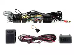
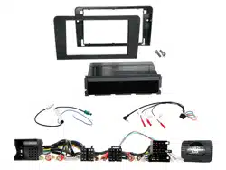
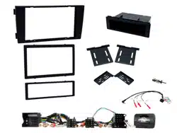
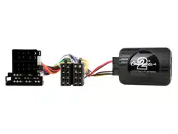
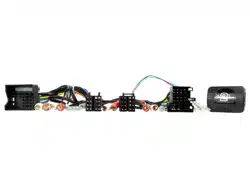
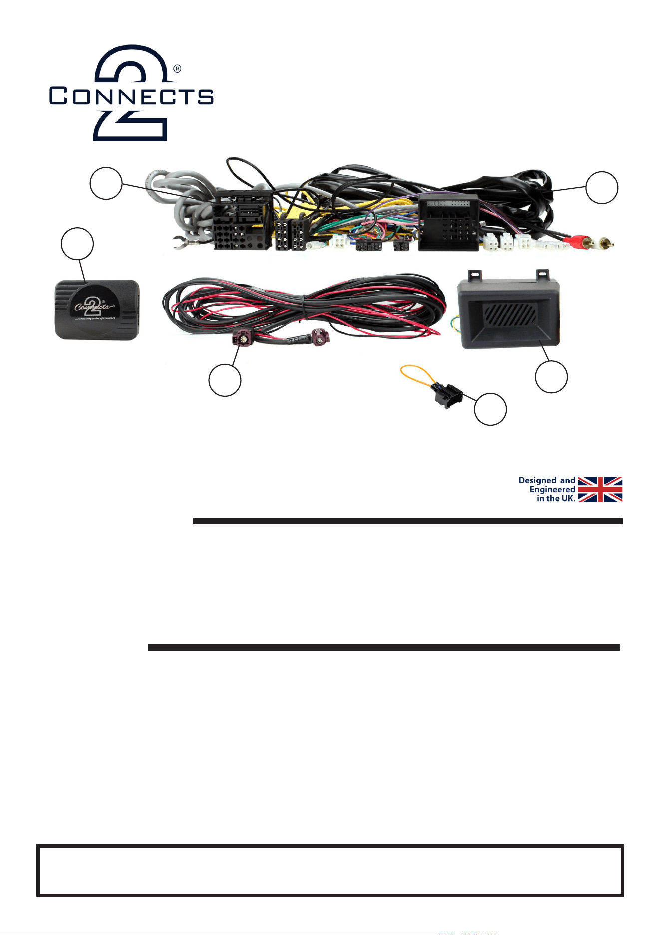
i. SWC Interface
ii. Main Wiring Harness
iii. Data Extension Lead (4 Pin Molex -> 4 Pin Molex)
iv. LVDS Extension Lead
v. Speaker Box
vi. MOST Loop
v
IN THE KIT
For non-amplied vehicles with NBT system only (not NBT Evo system).
The use of a MOST extension lead (sold separately) is needed in order to retain select features relating
to i-Drive/trip meter.
vi
2
CTSBM016.2_IG_v1
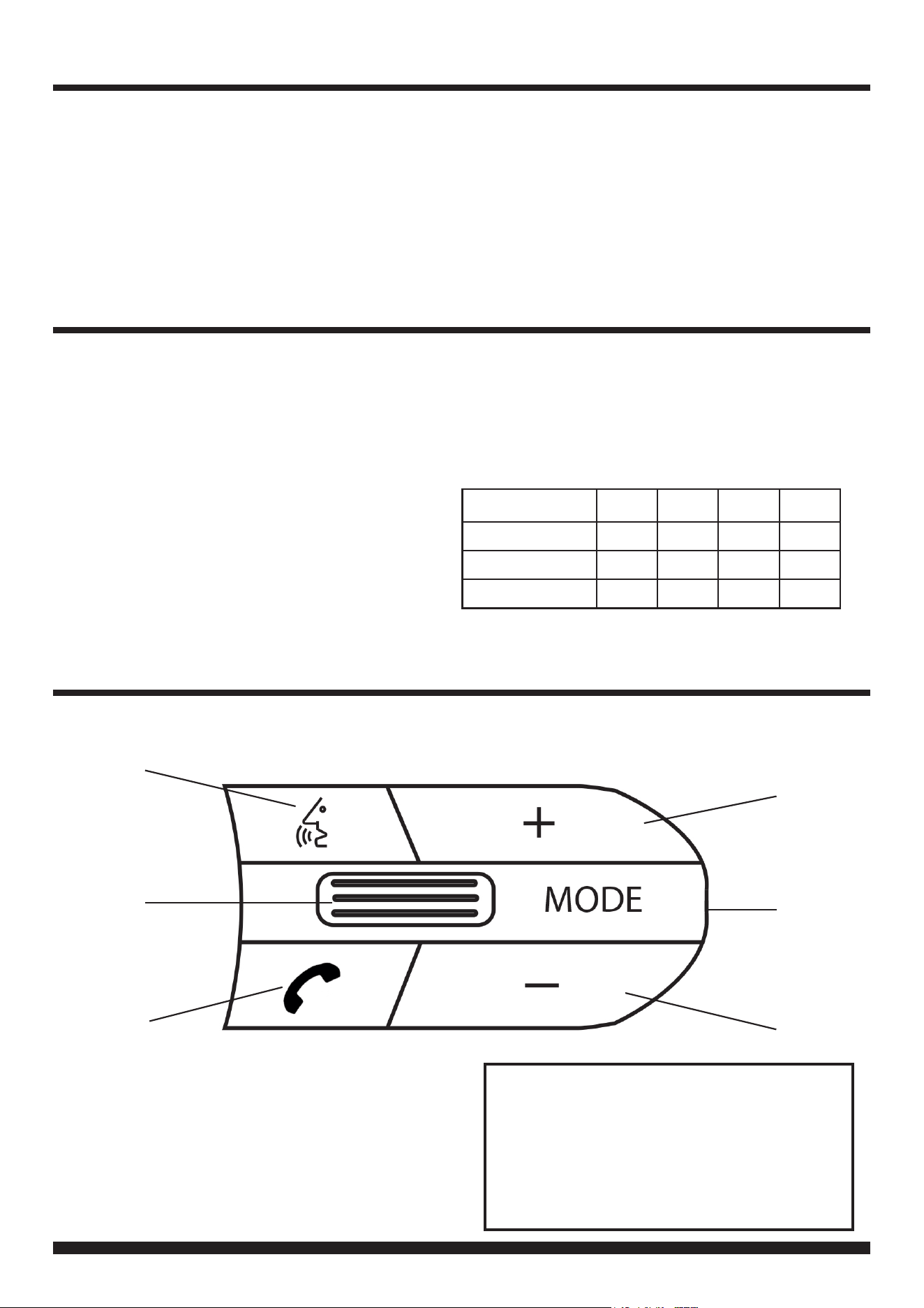
STEERING WHEEL CONTROL FUNCTIONALITY
The following diagram, though based on careful research, is an example only
Individual steering wheel control congurations may differ.
1
4
6
1. Voice Command (if stereo supports)
2. Track + / - (Push for Mute)
3. Pick Up (Short Press) Hang Up (Long Press)
4. Volume +
5. Mode / OEM Unit Control*
6. Volume -
5
3
2
Aftermarket Unit Control
If the OEM stereo has been retained during the
installation, hold Mode for 8-10 seconds until a
chime is heard from the interface speaker. The
SWC button will now control the OEM stereo. To
revert back to aftermarket unit control, hold Mode
for 8-10 seconds.
PRODUCT INFORMATION
CTSBM017.2
The CTSBM017.2 aids the installation of an aftermarket stereo into an OEM dashboard. It helps retain
steering wheel control presets as well as retaining vital features and functions which include parking
sensor audio and phone button functionality (if applicable). Our interface also allows for the retention of the
original head unit for the purpose of retaining key vehicle settings menus via the original display.
Please note: this product is for non-amplied vehicles only. Although the interface works to retain most settings,
some will remain “grey”. For these settings, the use of a MOST extension harness is needed (sold separately).
IN ISO CONNECTOR
Purple Right Rear Speaker +
Purple/Black Right Rear Speaker -
Green Left Rear Speaker +
Green/Black Left Rear Speaker -
Grey Right Front Speaker +
Grey/Black Right Front Speaker -
White Left Front Speaker +
White/Black Left Front Speaker -
ADDITIONAL CONNECTIONS
Lt. Green Park Brake
Pink Speed Pulse
Purple/White Reverse Gear
Brown Mute
WIRING KEY
Yellow Permanent 12V
Black Ground
Red Ignition 12V
Orange Illumination
ADDITIONAL DIPSWITCH SETTINGS
DIP4 is to be turned on if using a Pioneer head unit.
Chime Volume DIP1 DIP2 DIP3 DIP4
Low ON OFF OFF OFF
Medium OFF ON OFF OFF
High OFF OFF OFF OFF

3
Need help? Visit support.connects2.com/tickets/technical
CTSBM016.2_IG_v1
PRIOR TO INSTALLATION
INSTALLATION GUIDE
Read the whole manual prior to installation. Technical knowledge is necessary for installation. The place of
installation must be free of moisture and away from heat sources. Please ensure that the correct tools are using
during the installation to avoid damage to the vehicle or product. Connects2 can not be held responsible for the
installation of this product.
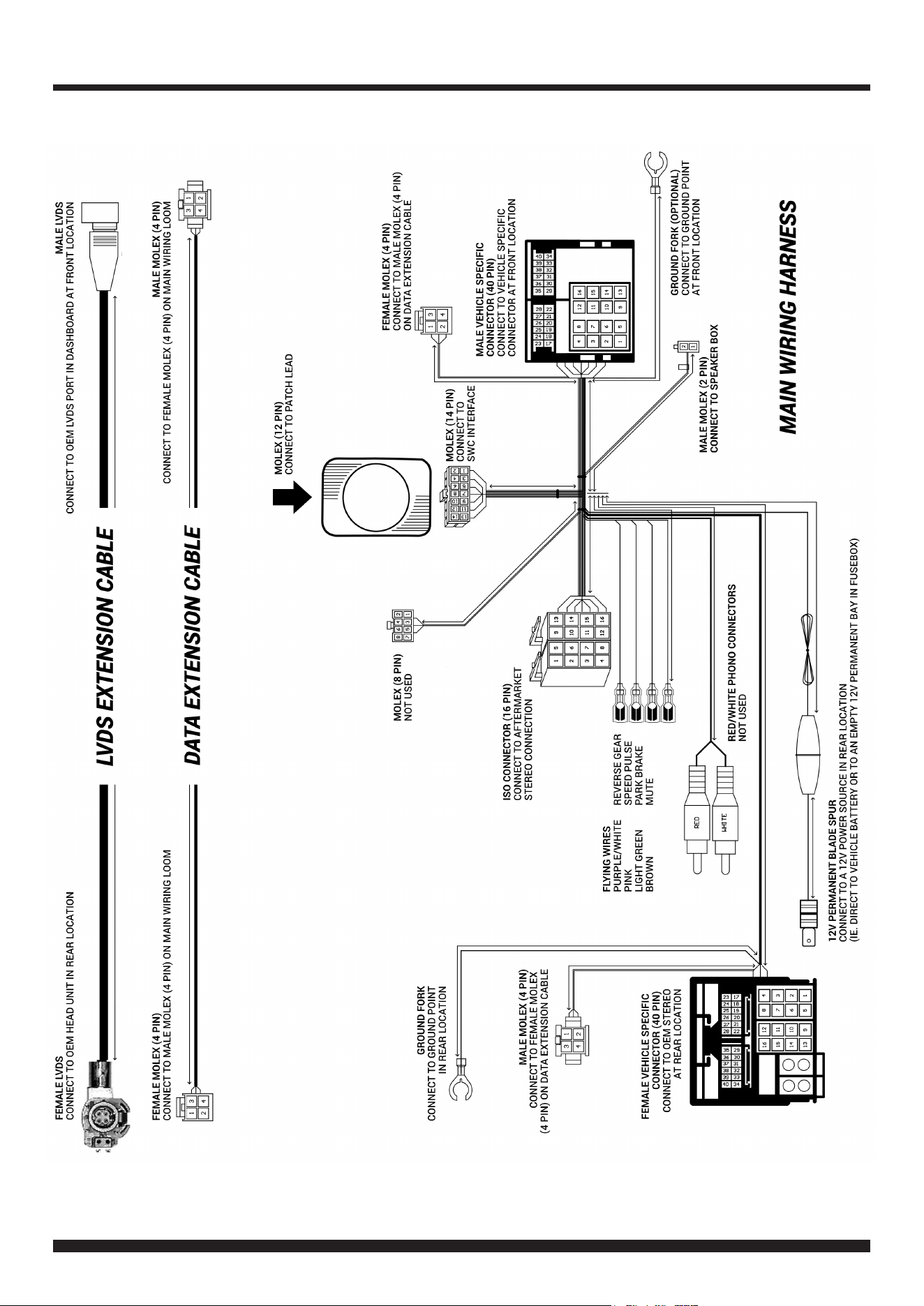
See wiring diagram on Pg.4 for more information
Before installation of the interface, the factory stereo must be removed, disconnected and relocated to a suitable
location in the rear of the vehicle.
To do this, please consult the vehicle owner’s manual/handbook or contact a tting professional.
10. Connect the male molex on the Data Extension Cable to the corresponding female molex connector on the Main
Wiring Harness.
CONNECTIONS AT REAR LOCATION (OEM UNIT)
1. Make the following connections at the rear location:
• 12V Permanent Blade Spur (Connect from main wiring harness to a desired 12V power source, e.g. direct to the
battery or to an empty 12V permanent bay in fusebox)
• 40 Pin Female Vehicle Specic Connector (Connect from main wiring harness to OEM stereo)
• Ground Fork (Connect from main wiring harness to a desired ground location)
• LVDS Extension Cable - Female End (Connect to OEM stereo)
• Data Extension Cable - Female End (Connect to the male molex located on the main wiring harness)
CONNECTIONS AT FRONT LOCATION (AFTERMARKET UNIT)
IMPORTANT: THIS STEP MUST BE COMPLETED BEFORE CONNECTING POWER TO THE INTERFACE.
FAILURE TO DO SO MAY RESULT IN A LACK OF FUNCTIONALITY AND THE NEED TO REINSTALL THE PRODUCT
!
13. Test the stereo and steering wheel control functionality for the correct operation before reassembling the vehicle
dashboard. If steering wheel control functions are unresponsive, uninstall the interface as well as the wiring and then
reinstall carefully in accordance with the above steps.
8. Connect the 2 Pin Molex connector on the main wiring harness to the Speaker Box.
5. Connect the MOST Loop to the vehicles pre-existing bre optic connection to retain the vehicles original menus.
3. Connect the opposite end of the stereo connection (patch) lead to the steering wheel control input on the back of
the aftermarket stereo.
NOTE: This may be a 3.5mm jack connector or a wired input depending on the brand of aftermarket stereo being tted.
Please consult the aftermarket stereo installation manual for further information on where to make the connection
2. Connect the 12 Pin connector from the desired stereo connection (patch) lead to the SWC interface.
4. Connect the 14 Pin Molex connector from the main wiring harness to the SWC interface.
6. Connect the power/speaker ISO connector to the power/speaker ISO connector at the rear of aftermarket stereo.
Note: For aftermarket stereos which do not have an ISO connector, please see ‘Wiring Key’ on Pg.2 for information on which wires to connect.
Some interfaces may also have additional ‘flying’ wires which can be connected to the vehicle to support various features i.e. parking brake
trigger, reverse gear and speed pulse. Details of these can be found under ‘Additional Connections’.
12. Connect the 40 Pin Male Vehicle-Specic Connector to the female connector from the vehicle.
9. Connect the Ground Fork to a suitable ground point.
11. Connect the Male LVDS connector to the OEM LVDS connector behind the dashboard (previously unplugged from
the OEM stereo).
7. Connect any/all additional ying wires to the back of the stereo.
4
CTSBM016.2_IG_v1
WIRING DIAGRAM