gravity & suction feed air discharge
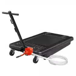
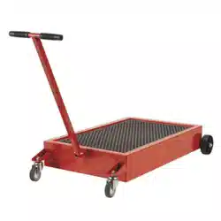
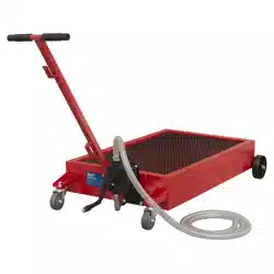
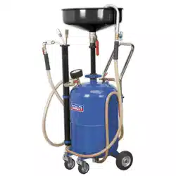
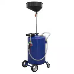
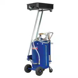
cantiLever oiL drainer
model no: aK462dX.v2
thank you for purchasing a sealey product. Manufactured to a high standard, this product will, if used according to these instructions,
and properly maintained, give you years of trouble free performance.
IMPORTANT: PLEASE READ THESE INSTRUCTIONS CAREFULLY. NOTE THE SAFE OPERATIONAL REQUIREMENTS, WARNINGS & CAUTIONS. USE
THE PRODUCT CORRECTLY AND WITH CARE FOR THE PURPOSE FOR WHICH IT IS INTENDED. FAILURE TO DO SO MAY CAUSE DAMAGE AND/OR
PERSONAL INJURY AND WILL INVALIDATE THE WARRANTY. KEEP THESE INSTRUCTIONS SAFE FOR FUTURE USE.
1. safetyi
1.1. generaL safety
Warning: ensure Health & Safety, local authority, and general workshop practice regulations are adhered to when using this
equipment.
9 Familiarise yourself with the application and limitations of the oil drainer, as well as the potential hazards.
Warning: disconnect the drainer from the air supply before changing accessories, servicing or performing any maintenance.
9 maintain the drainer in good condition (use an authorised service agent).
9 Replace or repair damaged parts. Use genuine parts only. Unauthorised parts may be dangerous and will invalidate the warranty.
9 Keep the work area clean, uncluttered and ensure there is adequate lighting.
9 Keep the drainer clean for best and safest performance.
9 maintain correct balance and footing. ensure the floor is not slippery and wear non-slip shoes.
9 Keep children and unauthorised persons away from the working area.
Warning: ensure correct air pressure is maintained and not exceeded.
9 Keep air hose away from heat, oil and sharp edges.
9 Check air hose for wear before each use, and ensure that all connections are secure.
8 do not use the drainer for any purpose other than that for which it is designed.
8 do not operate the drainer if any parts are damaged or missing as this may cause failure and/or personal injury.
8 do not stand on the drainer.
8 do not adjust or tamper with the safety valve.
8 do not move the drainer by the hose, or pull the hose sharply from the air supply.
8 do not place attachments close to your face and do not point hose at other persons or animals.
8 do not allow untrained persons to operate the drainer.
8 do not operate the drainer when you are tired, under the influence of alcohol, drugs or intoxicating medication.
8 do not leave the drainer operating unattended.
8 do not direct air from the air hose at yourself or others.
9 When not in use disconnect from the air supply, vent reservoir and store in a safe, dry, childproof area.
9 dispose of waste oil in accordance with local authority regulations.
Warning: do not pollute the environment by allowing uncontrolled discharge of waste oil.
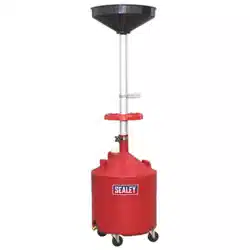
2. introduction
Steel fabricated 80ltr reservoir with suction probes and air discharge. Unit features cantilever oil drain pan which is suitable for use
eitherunderaliftorontheforecourt.Drainpanutilisesvacuumsuctionwheninthedownpositionandisttedwithabogeywheelfor
easy manoeuvring. Fitted with oil level indicator tube and supplied with mercedes adaptor plus a selection of probes.
3. specification
Model no: ........................................................aK462dX.v2
Capacity: ........................................................................ 80ltr
minimum Height to Pan: ............................................ 150mm
maximum Height to Pan: ......................................... 1600mm
Gravity Feed: .................................................................. Yes
Suction Feed: .................................................................. Yes
Gravity discharge: ........................................................... no
Air discharge: ................................................................. Yes
4. asseMbLy
note: numbers in brackets refer to item numbers on the parts diagram
4.1. Remove the bolt, washer and nut (48, 49 & 50) from the support bar (82).
4.2. Align the holes in the support bar (82) and the bracket on the oil pan (42), fit the bolt (48) and secure using the washer and nut (49 & 50).
4.3. loosen the handle retaining bolts at the back of the reservoir, insert the handle and tighten the bolts.
4.4. The oil drainer is now ready for use.
AK462dX Issue 5 (H, 3, 4, F) 20/06/19
Original Language Version
© Jack Sealey limited
Refer to
instruction
manual
Wear protective
gloves
Wear eye
protection
Wear protective
clothing
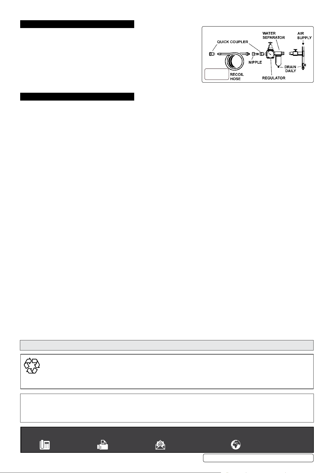
5. air suppLy
5.1. Ensuretheairvalveisinthe“O”positionbeforeconnectingtotheairsupply.
5.2. You will require an air pressure of 8 - 9 bar.
Warning: ensure the air supply is clean and does not exceed pressures
specified in these Instructions. Too high an air pressure and/or unclean air will
shorten the drainer life due to excessive wear, and may be dangerous, causing
damage and/or personal injury.
5.3. drain the air tank daily. Water in the air line may damage the drainer.
5.4. Clean the air inlet filter screen weekly. The recommended hook-up is shown in fig.1.
5.5. line pressure should be increased to compensate for unusually long air hoses.
6. operation
Warning: ensure that you read, understand and apply the safety instructions in Section 1.
Warning: ensure all valves are CloSed before applying air pressure to the unit.
note: Prior to initial use, open all valves, allow any residual pressures to vent and then close all the valves.
note: numbers in brackets refer to item numbers on the Parts diagram.
6.1. gravity feed oiL drainer
6.1.1. With the oil drainer pan in the raised position, open the oil input valve (28a) and the ball tap valve (27).
6.1.2. Remove the vehicle’s oil drain plug and the oil will drain via the oil pan into the reservoir under gravity.
6.2. creating a vacuuM
6.2.1. With all valves closed connect air supply to suction coupling (16) and turn on air supply at a pressure of 8 - 9 bar.
6.2.2. open ball valve (27a) and pressure in reservoir will begin to fall as shown on vacuum gauge (81).
6.2.3. When vacuum gauge (81) shows minus 0.8 bar - minus 0.9 bar close ball valve (27a), turn off air supply and disconnect supply line from
coupling (16).
6.2.4. The reservoir is now evacuated.
6.3. suction feed - probes
6.3.1. Create a vacuum, as described in paragraphs 6.2.1. to 6.2.3.
6.3.2. Select a probe to suit engine to be drained and connect to vacuum hose connection.
6.3.3. Remove engine oil dipstick and insert probe into dipstick tube.
6.3.4. open ball valve (34) and the oil will be drawn from the sump into the reservoir.
note: When sump is empty, air will be drawn up probe and reservoir will revert to atmospheric pressure (vacuum gauge will show zero).
6.4. suction feed - oiL pan
6.4.1. Create a vacuum, as described in paragraphs 6.2.1. to 6.2.3.
6.4.2. open the oil inlet valve (28a) and the oil will be sucked into the reservoir.
note: When oil pan is empty, air will be drawn into the tube (74) and reservoir will revert to atmospheric pressure (vacuum gauge will
show zero). once oil is evacuated you Must close valve 28a in order to prevent drain-back.
6.5. eMptying
6.5.1. ensure all valves are closed and connect air supply at a pressure of 2 - 2.5 bar to coupling (16).
6.5.2. open ball tap valve (27) and allow reservoir to pressurise until safety valve vents. Close ball tap valve (27) and disconnect air supply.
6.5.3. Place end of drain tube (105) in the waste oil container and then open ball valve (28).
6.5.4. When all waste oil is displaced from reservoir any remaining air pressure will be lost. Always confirm that reservoir pressure is zero before
closing valve (28).
note: never leave drainer with pressure, or vacuum, in the reservoir.
Original Language Version
© Jack Sealey limited
AK462dX Issue 5 (H, 3, 4, F) 20/06/19
g.1
sealey group, Kempson Way, suffolk business park, bury st edmunds, suffolk. ip32 7ar
01284 757500 01284 703534 sales@sealey.co.uk www.sealey.co.uk
environMent protection
Recycle unwanted materials instead of disposing of them as waste. All tools, accessories and packaging should be sorted, taken to
a recycling centre and disposed of in a manner which is compatible with the environment. When the product becomes completely
unserviceable and requires disposal, drain any fluids (if applicable) into approved containers and dispose of the product and fluids
according to local regulations.
note: It is our policy to continually improve products and as such we reserve the right to alter data, specifications and component parts without prior
notice. If you require documentation for alternative versions, please email or call our technical team on technical@sealey.co.uk or 01284 757505.
important: no liability is accepted for incorrect use of this product.
Warranty: Guarantee is 12 months from purchase date, proof of which is required for any claim.
Parts support is available for these products. Please email sales@sealey.co.uk or telephone 01284 757500