

© 2018 GeoVision, Inc. All rights reserved.
Under the copyright laws, this manual may not be copied, in whole or in part,
without the written consent of GeoVision.
Every effort has been made to ensure that the information in this manual is
accurate. GeoVision, Inc. makes no expressed or implied warranty of any kind
and assumes no responsibility for errors or omissions. No liability is assumed
for incidental or consequential damages arising from the use of the information
or products contained herein. Features and specifications are subject to
change without notice.
Note: No memory card slot or local storage function for Argentina.
GeoVision, Inc.
9F, No. 246, Sec. 1, Neihu Rd.,
Neihu District, Taipei, Taiwan
Tel: +886-2-8797-8377
Fax: +886-2-8797-8335
http://www.geovision.com.tw
Trademarks used in this manual: GeoVision, the GeoVision logo and GV
series productsare trademarks of GeoVision, Inc. Windowsis the registered
trademark of Microsoft Corporation.
May 2018
i
Preface
Welcome to the GV-VR360 IR Virtual Reality IP Camera User’s Manual. The instructions will
guide you through the installation and use of the camera.
This Manual is designed for the following models and firmware version:
Model Model Number Firmware Version
IR Virtual Reality IP Camera GV-VR360 V1.00

ii
Contents
Preface........................................................................................................................ i
Note for Connecting to GV-VMS.............................................................................. v
Note for Installing Camera Outdoor ........................................................................vi
Chapter 1 Introduction........................................................................................... 1
1.1 System Requirements.............................................................................................3
1.1.1 Software S
upported ..................................................................................... 3
1.2 Packing List ............................................................................................................4
1.3 Overview.................................................................................................................5
1.4 Installing the Camera ..............................................................................................6
Chapter 2 Getting Started...................................................................................... 8
2.1 Looking Up the IP Address......................................................................................8
2.1.1 Assigning an IP Address .............................................................................. 9
2.2 Accessing the Live View .......................................................................................10
2.2.1 The Live V
iew Window................................................................................11
2.2.2 The Control Panel of the Live View Window................................................12
2.2.3 Picture-in-Picture View................................................................................13
Chapter 3 Administrator Mode............................................................................ 14
3.1 Audio & Video Settings ......................................................................................... 15
3.1.1 Video Settings.............................................................................................15
3.1.2 Audio Settings.............................................................................................17
3.1.3 Metering......................................................................................................18
3.1.4 RTSP..........................................................................................................19
3.1.5 Live............................................................................................................. 19
3.2 Events and Alerts..................................................................................................20
3.2.1 I/O Control ..................................................................................................20
3.2.1.1 Input Settings..................................................................................20
3.2.1.2 Output Settings ...............................................................................21
3.2.2 E-mail .........................................................................................................22
3.3 Network ................................................................................................................23
3.3.1 LAN Configuration ......................................................................................23
3.3.2 Advanced TCP/IP .......................................................................................24
3.3.3 IP Filter .......................................................................................................26
3.4 Management.........................................................................................................27
3.4.1 Date and Time ............................................................................................27

iii
3.4.2 User Account ..............................................................................................28
3.4.3 Tools...........................................................................................................29
3.4.4 System Log.................................................................................................30
Chapter 4 YouTube Live Stream ......................................................................... 31
4.1 Setting YouTube Live Stream................................................................................32
4.2 Configuring Live Stream Settings..........................................................................34
4.3 Starting Live Stream..............................................................................................35
Chapter 5 Smart Device Connection .................................................................. 36
Chapter 6 Advanced Applications ...................................................................... 37
6.1 Upgrading System Firmware................................................................................. 37
6.1.1 Using the Web Interface .............................................................................37
6.1.2 Using the GV-IP Device Utility.....................................................................38
6.2 Restoring to Factory Default Settings....................................................................40
6.2.1 Using the Web Interface .............................................................................40
6.2.2 Directly on the Camera ...............................................................................40
Chapter 7 VMS Configurations ........................................................................... 42
7.1 Setting Up IP Cameras on GV-VMS......................................................................43
Appendix ................................................................................................................. 46
A. RTSP Protocol Support.............................................................................................46

iv
Regulatory Notices
FCC Notice
This equipment has been tested and found to comply with the limits for a Class A digital
device, pursuant to part 15 of the FCC Rules. These limits are designed to provide reasonable
protection against harmful interference when the equipment is operated in a commercial
environment.
Class A
This equipment generates, uses, and can radiate radio frequency energy and, if not installed
and used in accordance with the instruction manual, may cause harmful interference to radio
communications. Operation of this equipment in a residential area is likely to cause harmful
interference in which case the user will be required to correct the interference at their own
expense.
CE Notice
This is a Class A product. In a domestic environment, this product may cause radio
interference in which case the user may be required to take adequate measures.
RoHS Compliance
The Restriction of Hazardous Substances (RoHS) Directive is to forbid the use of hazardous
materials of production. To meet the RoHS Directive requirements, this product is made to be
RoHS compliant.

v
Naming Definition
GV-VMS
GeoVision Video Management System for IP cameras.
Note for Connecting to GV-VMS
The camera is designed to work with and record on GV-VMS, a video management system.
Once the camera is connected to the GV-VMS, the resolution set on the GV-VMS will override
the resolution set on the camera’s Web interface. You can only change the resolution settings
through the Web interface when the connection to the GV-VMS is interrupted.

vi
Note for Installing Camera Outdoor
When installing the camera, be sure that:
1. The camera is set up above the junction box to prevent water from entering the camera
along the cables.
2. Any PoE, power, audio and I/O cables are waterproofed using waterproof silicon rubber
or the like.
3. The screws are tightened and the cover is in place after opening the camera cover.

vii
Optional Accessories
Optional devices can expand your camera’s capabilities and versatility. Contact our sales
representatives for more information.
Device Description
GV-PoE Switch
GV-PoE Switch is designed to provide power along with
network connection for IP devices. GV-PoE Switch is
available in various models with different numbers and
types of ports.
GV-Relay V2
GV-Relay V2 is designed to expand the voltage load of
GV-IP devices. It provides 4 relay outputs, and each can be
set as normally open (NO) or normally closed (NC)
independently as per your requirement.
Power Adapter
Contact our sales representatives for the countries and
areas supported.

1
Chapter 1 Introduction
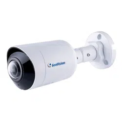
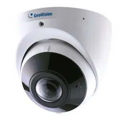
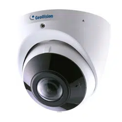
GV-VR360 is a Virtual Reality IP camera made true with two 4 MP fisheye panoramic cameras.
The camera provides a live view of the surveillance area with an all-inclusive 720° angle
range of view and extended depth of field, enabling a total coverage of wide open areas.
When streamed online or viewed through the GV-Eye or YouTube mobile app, users can
watch the 720°, VR video from the camera for an immersive experience.
Equipped with IR-cut filter, IR LEDs having an effective distance of up to 10 m (32 ft) and
WDR, GV-VR360 is capable of day and night surveillance under contrasting illumination
conditions. Utilizing H.265 video codec, the camera allows better compression ratio while
maintaining high image quality at reduced network bandwidths. The camera adheres to IK10
and IP67 standards.

Introduction
2
1
Features:
Dual 4MP fisheye provides 720° panoramic view with no blind spots
1/2.9’’ progressive scan low lux CMOS
Dual streams from H.265 or H.264
Up to 30 fps at 3840 x 2160
Day and night (with removable IR-cut filter)
Intelligent IR
4 IR LEDs
IR distance up to 10 m (32 ft)
One-way audio
Built-in / external microphone
1 sensor input and 1 alarm output
DC 12V / PoE (PoE+, IEEE 802.3at)
Vandal resistance (IK10 for metal casing)
Ingress protection (IP67)
VR Mode for YouTube & GV-Eye
Smart device APP support
Live streaming via YouTube
Defog
3 languages on Web interface
ONVIF (Profile S) conformant
3
1.1 System Requirements
CPU Intel® 6
th
generation Core
TM
i3
Memory 4 GB or above
On Board Graphics Intel® HD Graphics 500 series or above
OS Windows 7 Service Pack 1 / Windows 10 or above
Web Browser Internet Explorer 10 / 11 or above
1.1.1 Software Supported
GV-VMS V18.1
GV-Control Center V3.6.0.0
GV-Edge Recording
Manager (for Windows)
V.1.4.0.0
GV-Recording Server V1.4.0.0 + Patch for live stream only
GV-Eye V2.5.2 for IOS and V2.5.1 for Android
Introduction
4
1
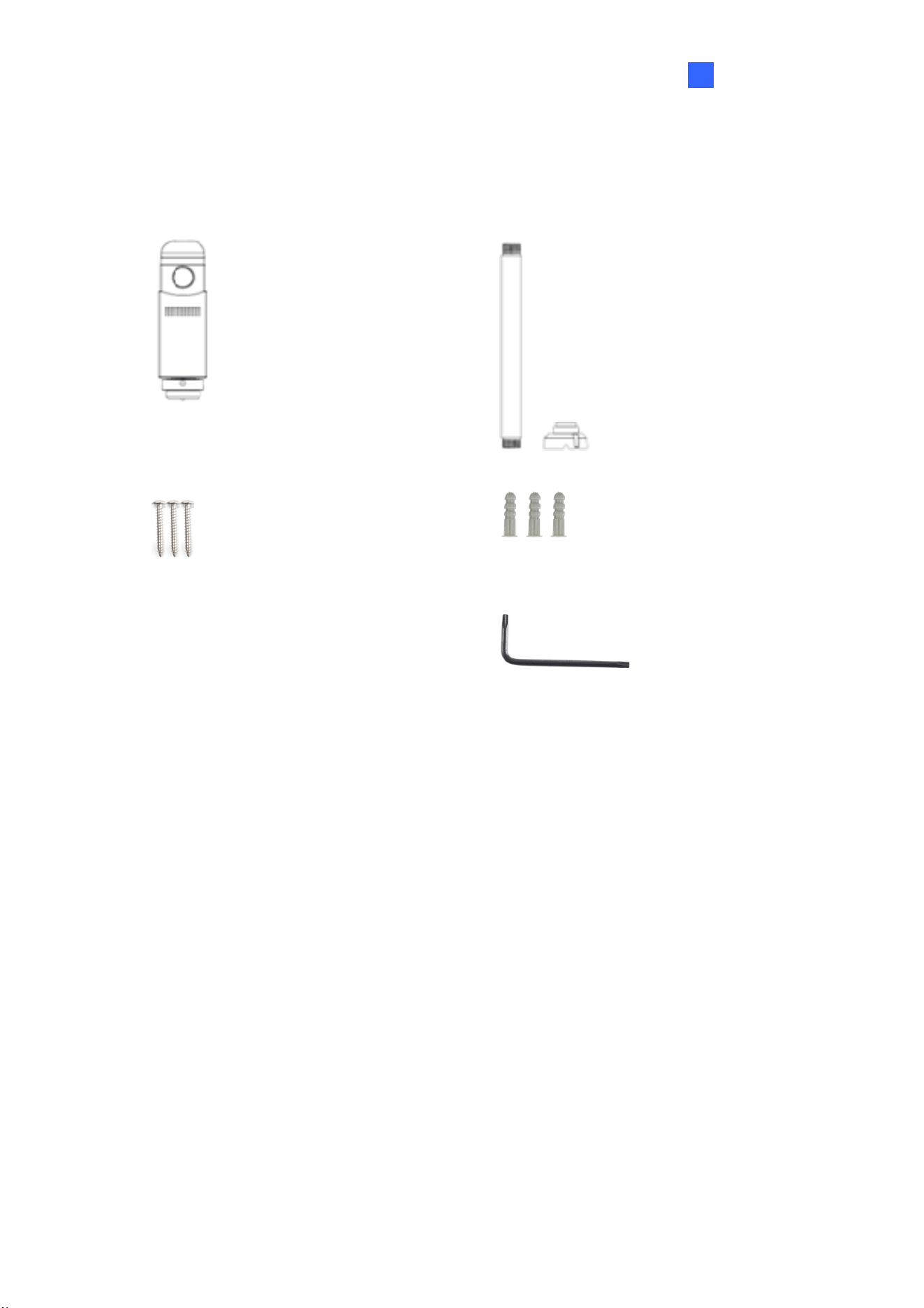
1.2 Packing List
IR Virtual Reality IP Camera Mount Kit
Screw x 3 Screw Anchor x 3
Hex Key Torx Wrench
Silica Gel Bag
Download Guide
Warranty Card
5
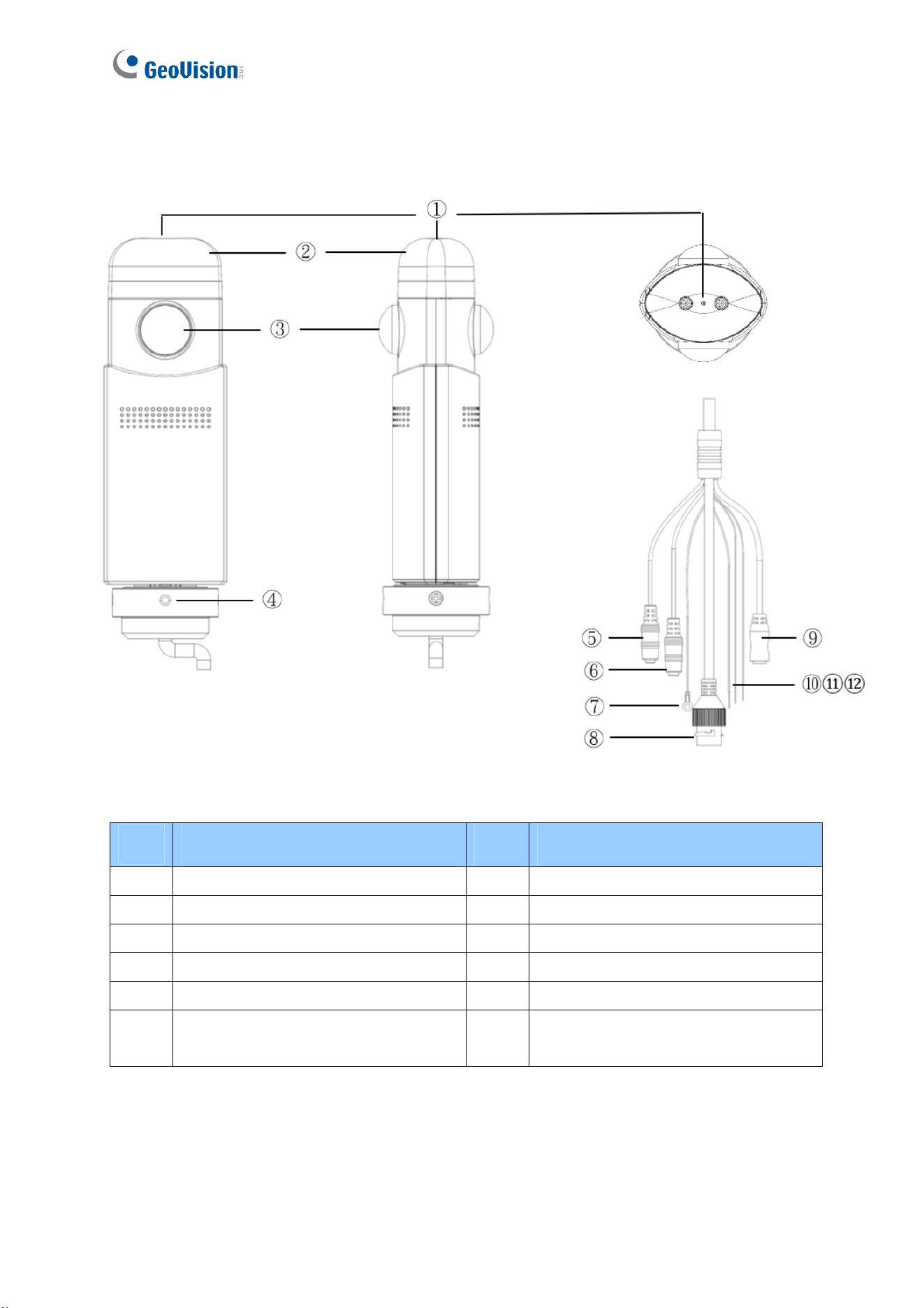
1.3 Overview
Figure 1-1
No. Description No. Description
1 Built-in microphone 7 Earth ground (M3 terminal)
2 IR LED 8 RJ45 waterproof
3 Fisheye lens 9 DC 12V jack (black)
4 Socket set screw 10 Digital input (white cable)
5 Audio in (pink jack) 11 Digital output (green cable)
6
Audio out (green jack, currently not
functional)
12 Ground wire (black cable)

Introduction
6
1
1.4 Installing the Camera
The camera is designed for outdoors. With the standard package, you can install the camera
on the ceiling.
1. Adjoin the base with the straight tube by turning it clockwise.
Figure 1-2
2. Thread the cables of the camera to the base end through the opposite end of the straight
tube and rotate the straight tube clockwise to attach it to the camera.
Figure 1-3
3. Mount the camera onto the ceiling using the mounting kit and the supplied screws and
screw anchors.
Figure 1-4
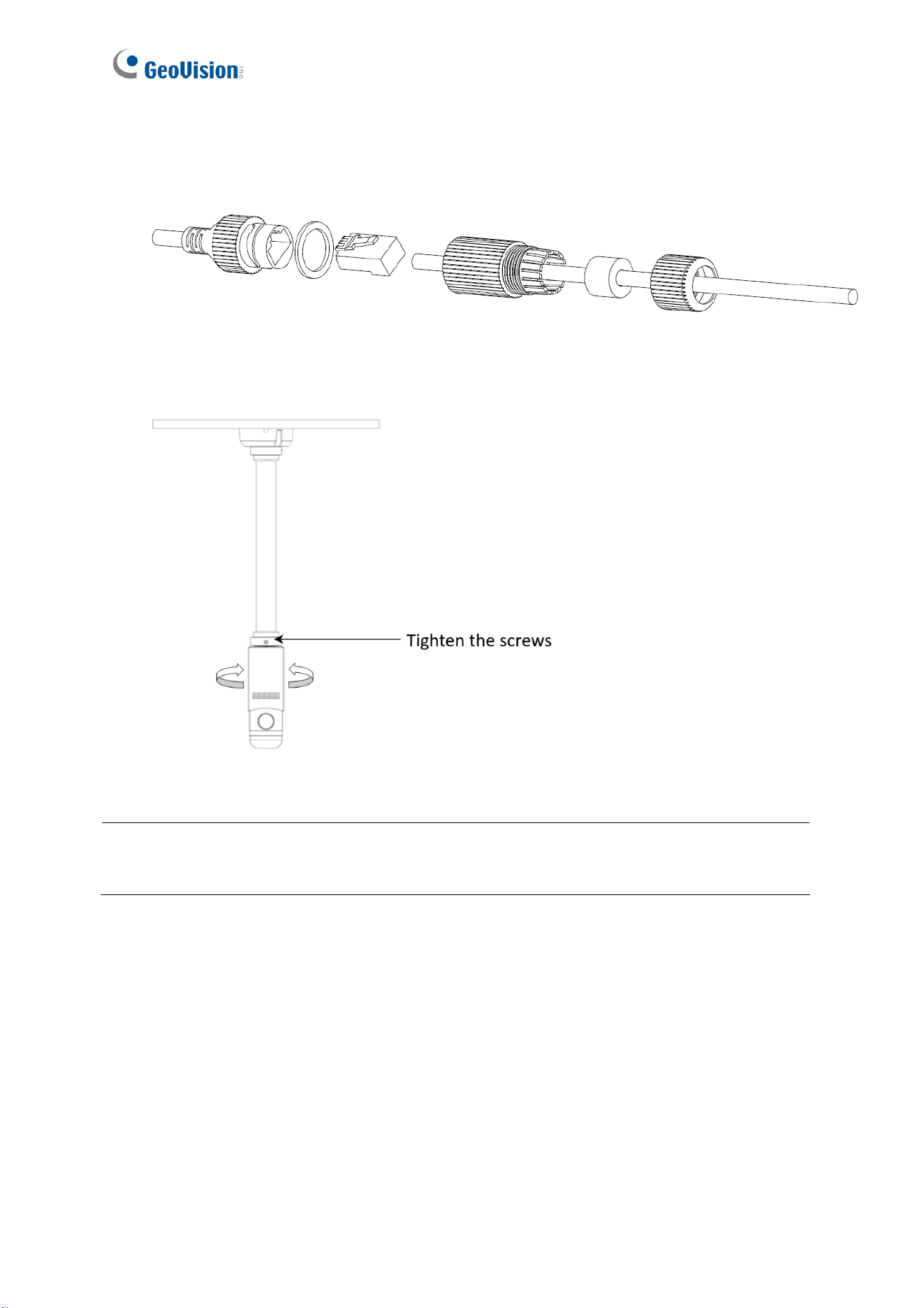
7
4. Connect a network cable to the camera. Optionally waterproof the network cable by
disassembling the cap of the network connector and thread the network cable as
illustrated below.
Figure 1-5
5. Rotate the camera to adjust for the desired angle and tighten the screws to fixate its
position.
Figure 1-6
Note: Image at a radius of approximately 1.5 m (4.9 ft) away from the camera will be slightly
obscured in panoramic view.

Getting Started
8
2
Chapter 2 Getting Started
2.1 Looking Up the IP Address
By default, GV-VR360 is assigned with a dynamic IP address when the camera is connected
to a network with DHCP server. This IP address remains unchanged unless you unplug or
disconnect your camera from the network.
Note: If your router does not support DHCP, the default IP address will be 192.168.0.10. In
this case, it is strongly recommended to modify the IP address to avoid IP address conflict
with other GeoVision IP devices under the same LAN. To change the IP address, see 2.1.1
Assigning an IP Address.
Follow the steps below to check the GV-VR360’s dynamic IP address:
1. Download and install the GV-IP Device Utility program (V8.7.1.0 or later) from our
website
.
Note: The PC installed with GV-IP Device Utility must be under the same LAN as the
camera you wish to configure.
2. Select Start on the PC, point to Programs and select GV-IP Device Utility. The Utility
window appears and automatically searches for the IP devices under the same LAN.
Figure 2-1
3. Click the Name or Mac Address column to sort.
4. Use the Mac address of the camera to look up its IP address.
9
2.1.1 Assigning an IP Address
When the DHCP server on your network is unavailable or disabled, the camera can be
accessed by the default IP 192.168.0.10. To modify the static IP address, log on to the Web
interface and access the network setting page.
1. Open your Web browser and type the default IP address http://192.168.0.10
.
2. Type the default account and password admin and click Apply.
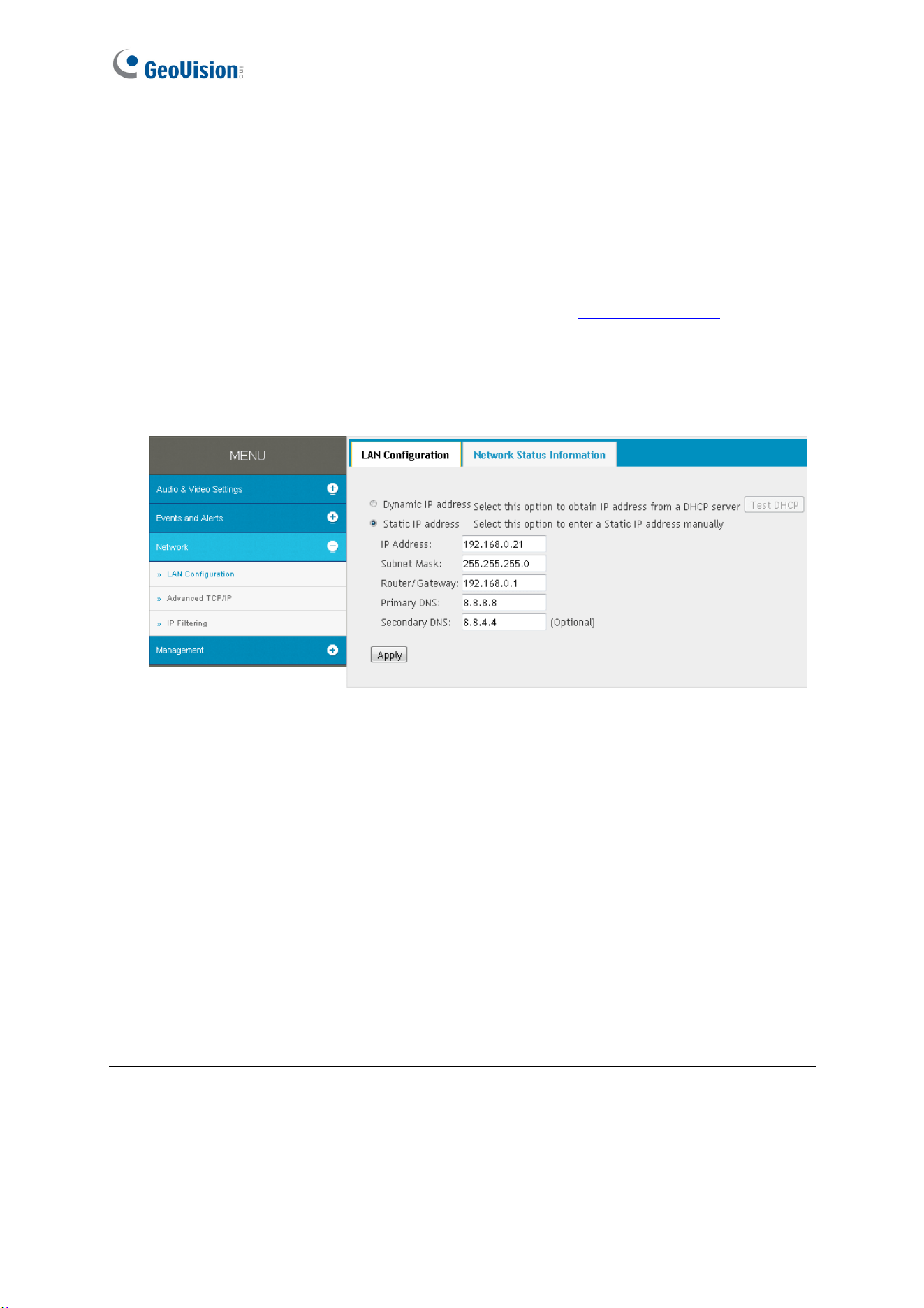
3. Click System Settings at the top, select Network and click LAN Configuration. This
page appears.
Figure 2-2
4. Select Static IP address and type the required network information.
5. Click Apply. The camera is now accessible through the assigned IP address.
IMPORTANT:
1. Use the dynamic DNS Service to obtain a domain name linked to the camera’s changing
IP address before you start using the dynamic IP address. For details on Dynamic IP
Address, see 3.3.2 Advanced TCP/IP and 3.3.1 LAN Configuration.
2. If Dynamic IP Address is enabled and you cannot access the camera, you may have to
reset it to its factory default settings and perform the network settings again. To restore
to factory settings, see 6.2 Restoring to Factory Default Settings.
Getting Started
10
2
2.2 Accessing the Live View
Two types of users are allowed to log on to the GV-VR360: Administrator and Guest. The
Administrator has full access to all system configurations of the camera, while the Guest can
only access its live view and network status.
Once the camera is connected to the network, follow the steps below to access its live view:
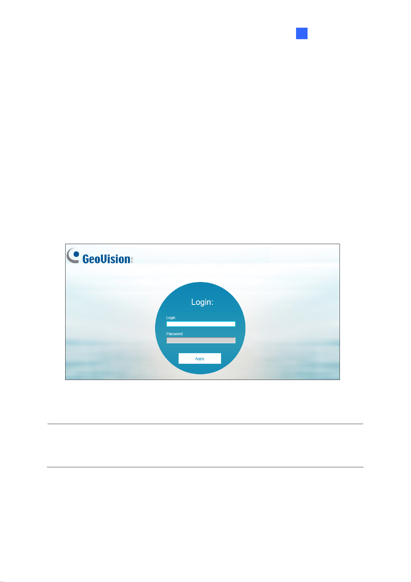
1. Open your Web browser and type the IP address or domain name of the camera in the
Location/Address bar. To look up the IP address, see 2.1 Looking Up the IP Address.
2. Enter the account and password of the camera.
The default account and password for Administrator are admin.
The default account and password for Guest are guest.
Figure 2-3
3. The live view of GV-VR360 is now displayed on your browser.
Note: Before accessing the camera’s live view on Microsoft Internet Explorer, you must
allow ActiveX Controls and perform a one-time installation of GeoVision’s ActiveX
component onto your computer.
11
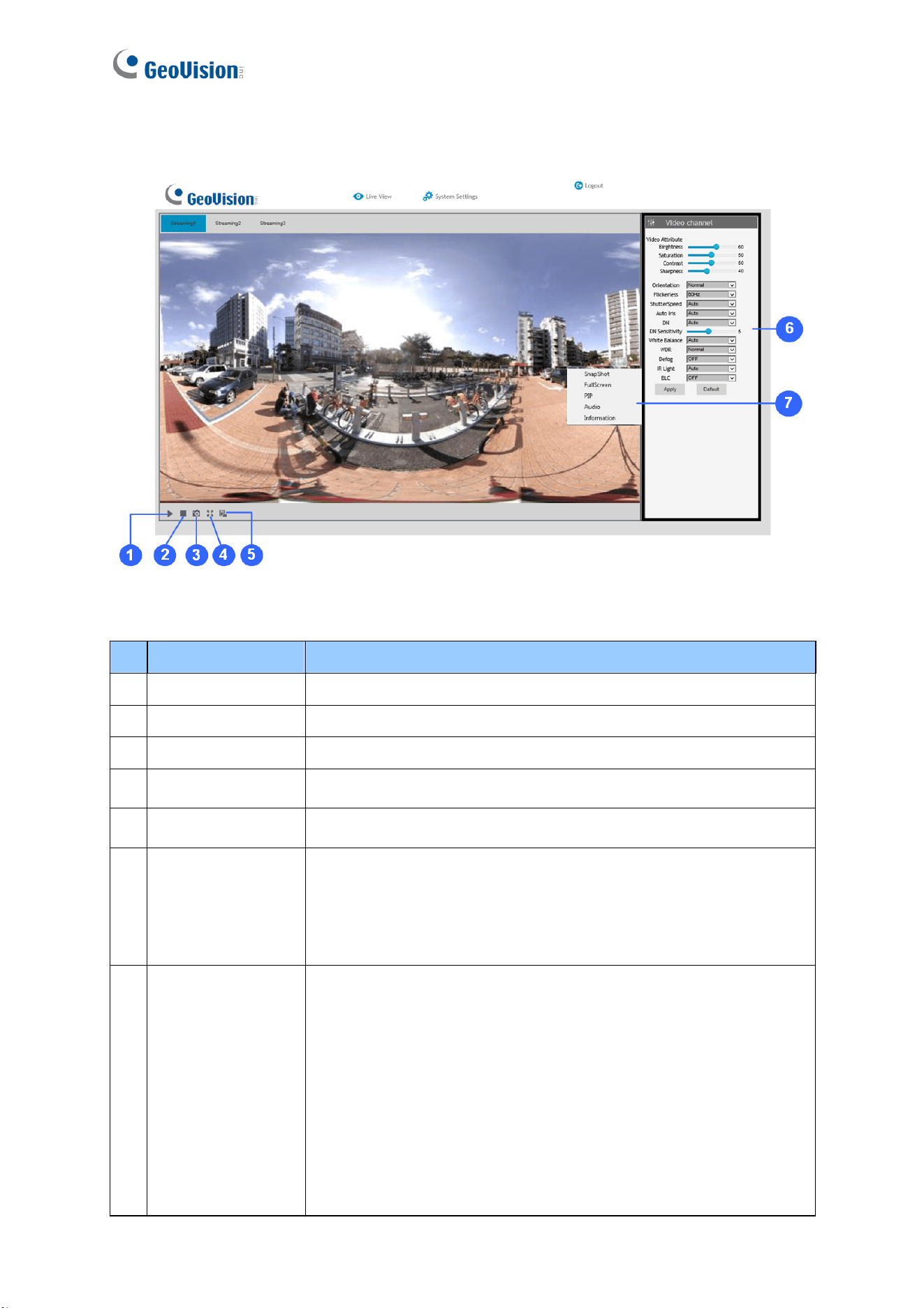
2.2.1 The Live View Window
Figure 2-4
No. Name Function
1 Play Plays live video.
2 Stop Stops playing video.
3 Snapshot Takes a snapshot of the live video.
4 Full Screen Switches to full screen view.
5 File Save Records live video to the local computer.
6 Control Panel
Access and configure the following image settings: Video
Attribute, Orientation, Flickerless, D/N, D/N Sensitivity, White
Balance, WDR, Defog, IR Light and 360.
--- See 2.2.2 The Control Panel of the Live View Window.
7 Pop-up Menu
Right-click on the live view image to have the following options:
Snapshot: Takes a snapshot of the live video.
Full Screen: Switches to full screen view.
PIP: Enables an inset window for a close-up view of the live
view. See 2.2.3 Picture-in-Picture View.
Audio: Receives live audio from the surveillance site.
Information: Displays the video codec, resolution, FPS and
streaming speed of the live video.
Getting Started
12
2
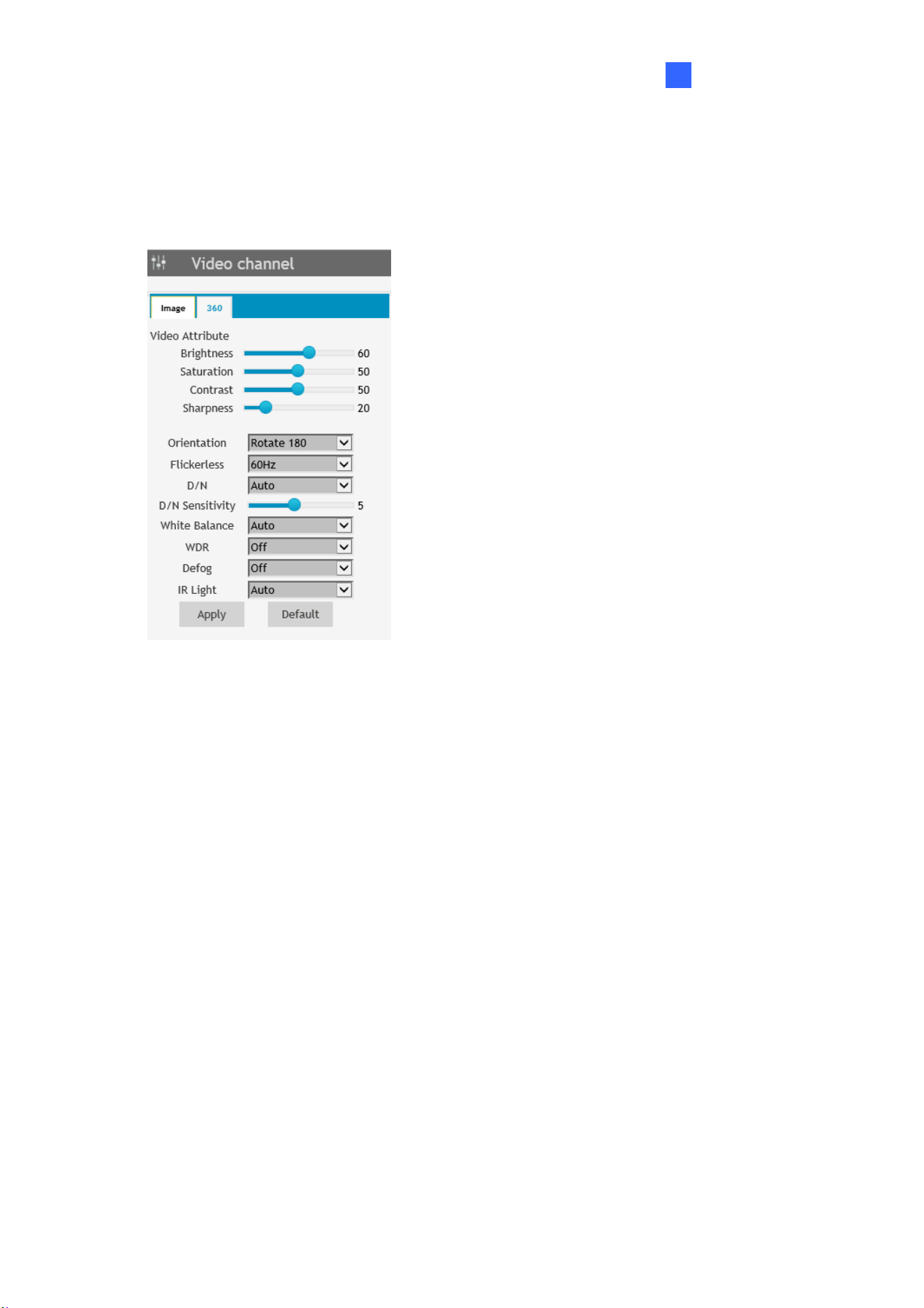
2.2.2 The Control Panel of the Live View Window
Using the control panel on the right side of the Live View window, you can adjust the following
image settings. Note these settings are only accessible by the Administrator.
Figure 2-5
[Image]
Video Attributes: Adjusts the Brightness, Saturation, Contrast and Sharpness of the live
image.
Orientation: Changes the orientation of the image in live view.
Flickerless: Manually select the frequency of your camera’s image, between 50 Hz and
60 Hz, to match the frequency of the light sources of the surveillance site, e.g. fluorescent
lighting. If the frequencies don’t match, faint light and dark bars may appear in the images.
Check the power utility to determine which frequency is used at your area.
D/N: Select Auto for the camera to automatically switch between day mode and night
mode depending on the amount of light detected. Select Black and White to switch the
camera to night mode. Select Color to switch the camera to day mode.
D/N Sensitivity: Sets the sensitivity of the light sensors used for switching between day
and night modes, from 1 to 10. The higher the value, the more sensitive they are to light.
White Balance: The camera automatically adjusts the color to be closest to the image
you are viewing. Select from the following: Auto, Outdoor, Fluorescent, and
Incandescent.
13
WDR (Wide Dynamic Range): Adjusts for clear images when the scene contains very
bright and very dark areas at the same time. Select Strong to bring out details of the dark
areas of the scene or Normal for a balanced effect.
Defog: Select Auto to automatically enhance the visibility of images. Select Off to
disable the function.
IR Light: Select Auto to automatically enhance the visibility of images using intelligent IR.
Select Off to disable the function.
[360]
360: Adjust the Max. and Min. Stich values to set the range of the panoramic view.
Click Apply to save the configurations set. The changes take effect only after the
configurations have been saved.
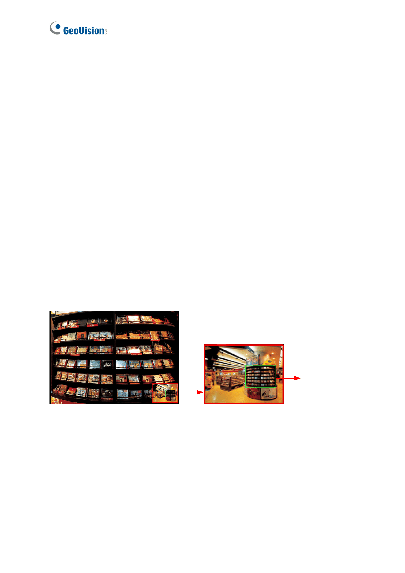
2.2.3 Picture-in-Picture View
The Picture-in-Picture (PIP) view allows you to zoom in for a closeup view of the image while
navigating on the live view through an inset window.
Inset window
Navigation box
Figure 2-6
1. Right-click on the live view and select PIP. An inset window appears.
2. Click the inset window. A navigation box appears.
3. Move the navigation box within the inset window to have a closeup view of the area
select.
4. Hover the cursor over any one of the navigation box’s four corners to adjust its size.
5. To exit the PIP view, right-click on the live view and deselect PIP.
14
Chapter 3 Administrator Mode
The Administrator can access and configure the GV-VR360 over the network. Click System
Settings at the top of the Web interface to access the following four configuration tabs: Audio
& Video Settings, Events and Alerts, Network and Management.
Figure 3-1
List of Configurations
See the table below for the settings available on the Web interface. Find the topic of interest
by referring to the section number prefixed to each option.
3.1 Audio & Video Settings
3.1.1 Video Settings
3.1.2 Audio Settings
3.1.3 Metering
3.1.4 RTSP
3.1.5 Live
3.2 Events and Alerts
3.2.1 I/O Control
3.2.2 E-mail
3.3 Network
3.3.1 LAN Configuration
3.3.2 Advanced TCP/IP
3.3.3 IP Filtering
3.4 Management
3.4.1 Date and Time
3.4.2 User Account
3.4.3 Tools
3.4.4 System Log
15
3.1 Audio & Video Settings
The GV-VR360 supports two streams, Streaming 1 and Streaming 2, which allow separate
codec and resolution settings through a single video transmission. In a bandwidth-limited
network, such as mobile phone surveillance, this dual-stream feature allows you to view live
video in a lower resolution and codec (Streaming 2) while recording in a higher resolution and
codec (Streaming 1).
Note: When the GV-VR360 is connected to a video management software and/or app,
changing its Audio or Video Settings may result in temporary disconnection or image freeze,
for about 40 ~ 60 seconds.
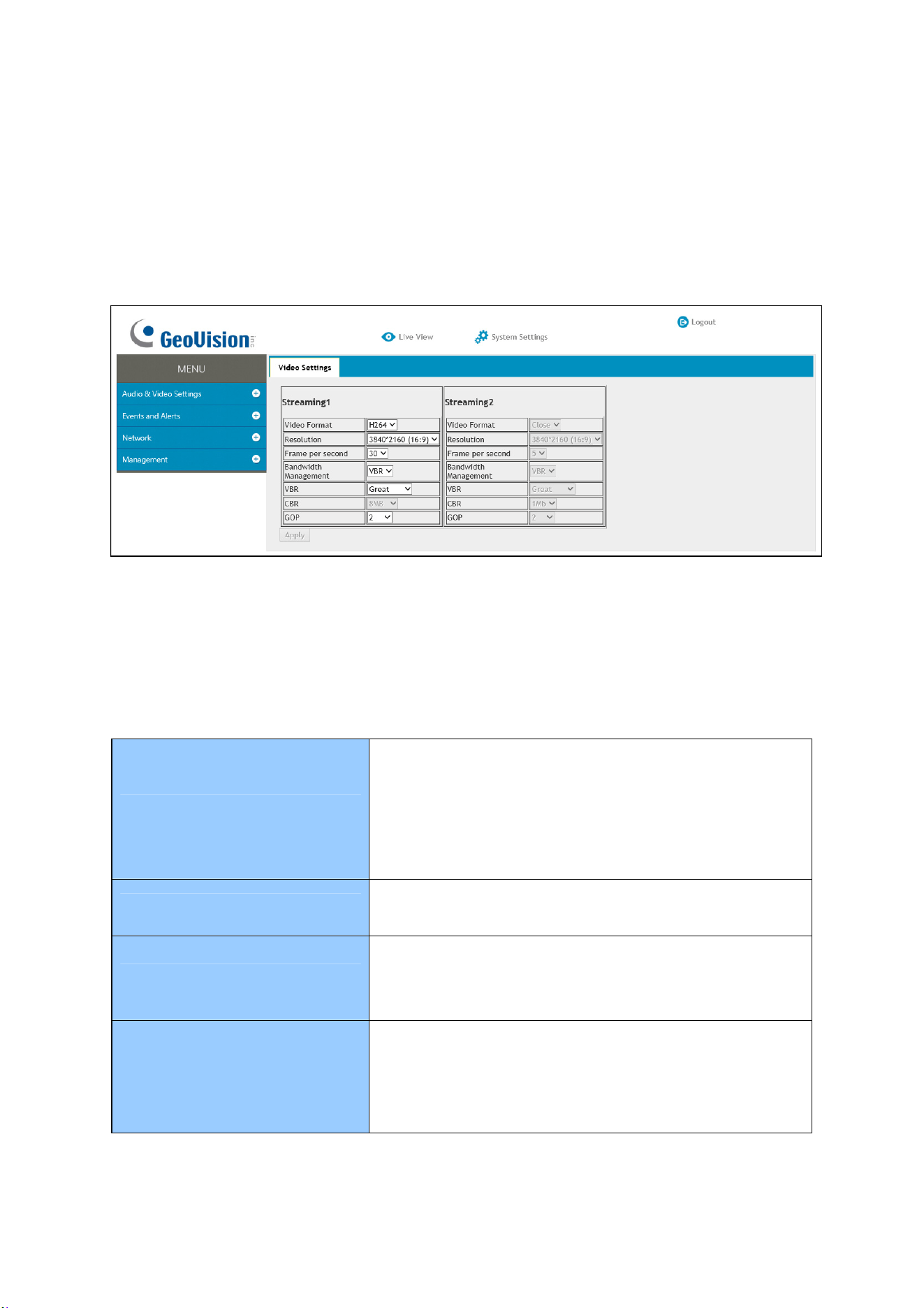
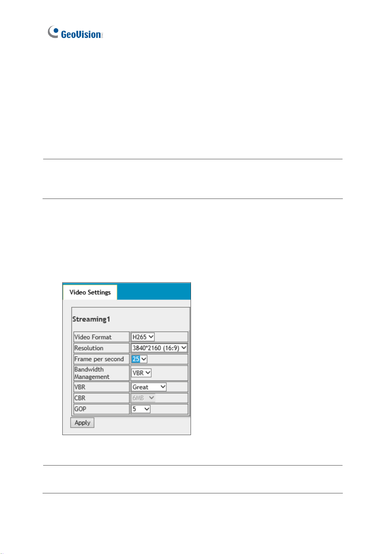
3.1.1 Video Settings
In Video Settings, you can configure your video stream settings, such as H.264/H.265 video
format, resolutions, and FPS or enable / disable streaming 2.
Figure 3-2
Note: Streaming 2 is disabled by default. To enable streaming 2, change the FPS of
streaming 1 to 25 or lower.

Administrator Mode
16
3
[Video Format] Select either H.265 or H.264 as the codec type.
Note: H.265 video codec is not supported for YouTube streaming.
[Resolution] Select the desired resolution for video streaming from the drop-down list. The
resolution of Streaming 2 will always be the same as Streaming 1.
[Frame per Second] Select the desired FPS for video streaming from the drop-down list. The
FPS of Streaming 2 is always kept at 5.
[Bandwidth Management]
You can configure the bitrate settings to control your bandwidth usage.
VBR (Variable Bitrate): The quality of the video stream is kept as constant as possible at
the cost of a varying bitrate. The bandwidth is much more efficiently used than the CBR.
Select one of the 5 standards for the image quality: Poor, Fair, Good, Great or
Excellent.
CBR (Constant Bitrate): CBR is used to achieve a specific bitrate by varying the quality
of the video stream. The bitrates available for selection depend on the resolution set.
[GOP]
Set the maximum number of seconds between every key frame. The default is 2 (seconds).
17
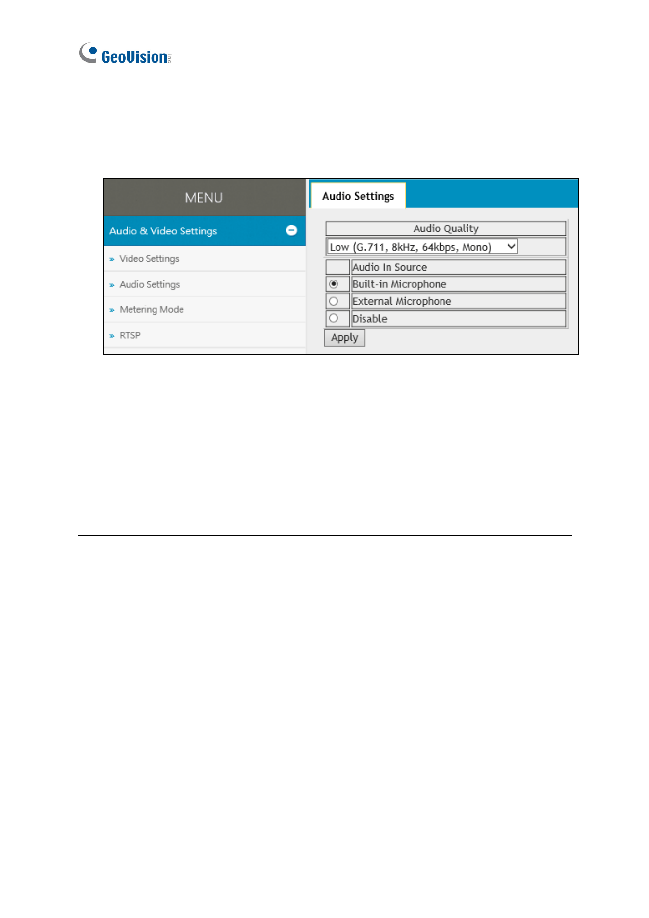
3.1.2 Audio Settings
You can enable the microphone and select the audio quality from Low , Normal or YouTube.
Select Built-in Microphone or External Microphone as the source of audio input.
Figure 3-3
Note:
1. Normal audio quality and audio for YouTube streaming require AAC audio codec
(optional)
2. When YouTube is selected under audio quality, there will be no audio support for
the camera’s Web interface and all video management software and app connected
to the camera.
Administrator Mode
18
3
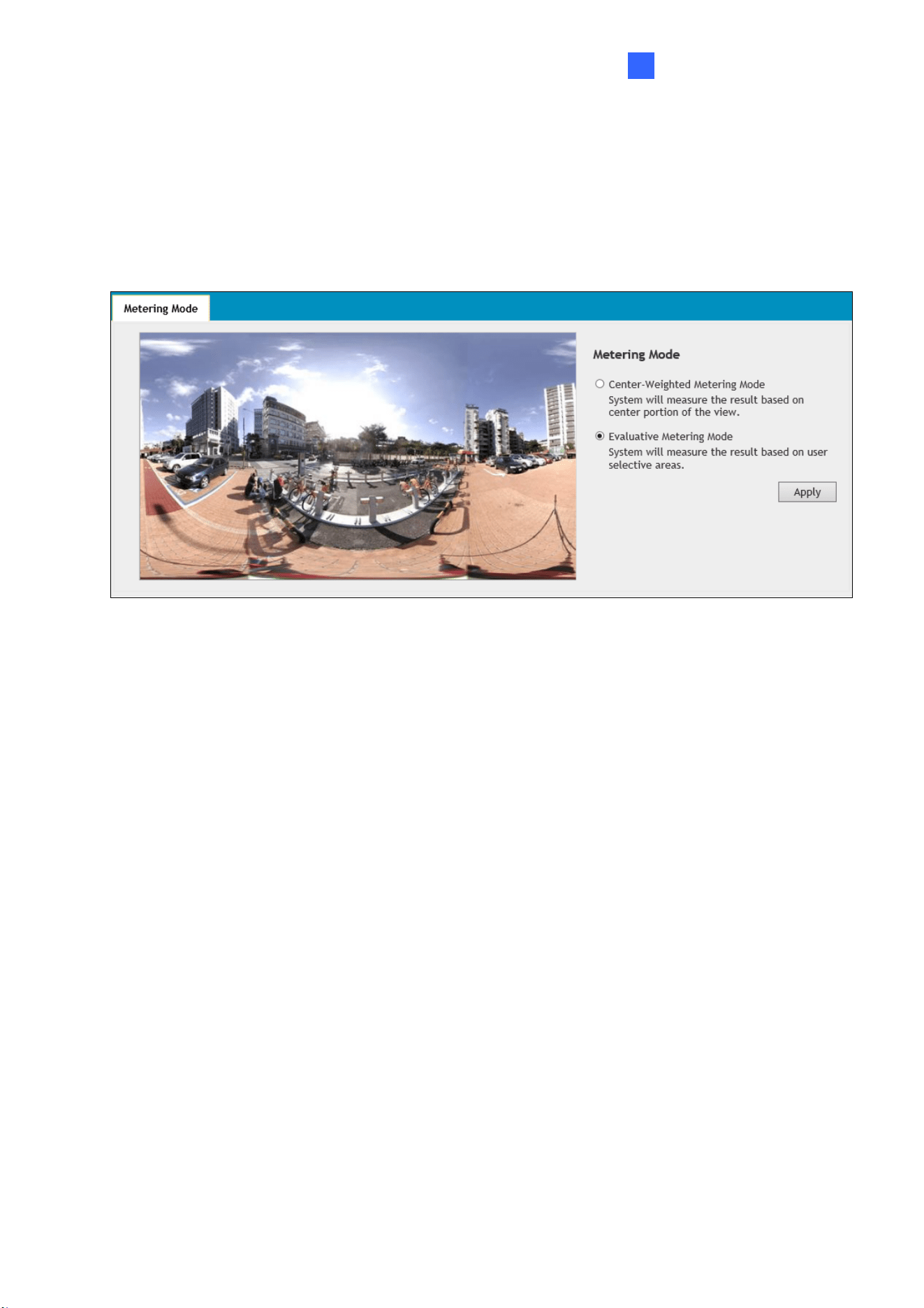
3.1.3 Metering
Select between Center-Weighted Metering Mode and Evaluative Metering Mode for the
camera to automatically measure the intensity of light. For Evaluative Metering Mode, click on
a desired location on the image.
Figure 3-4
19
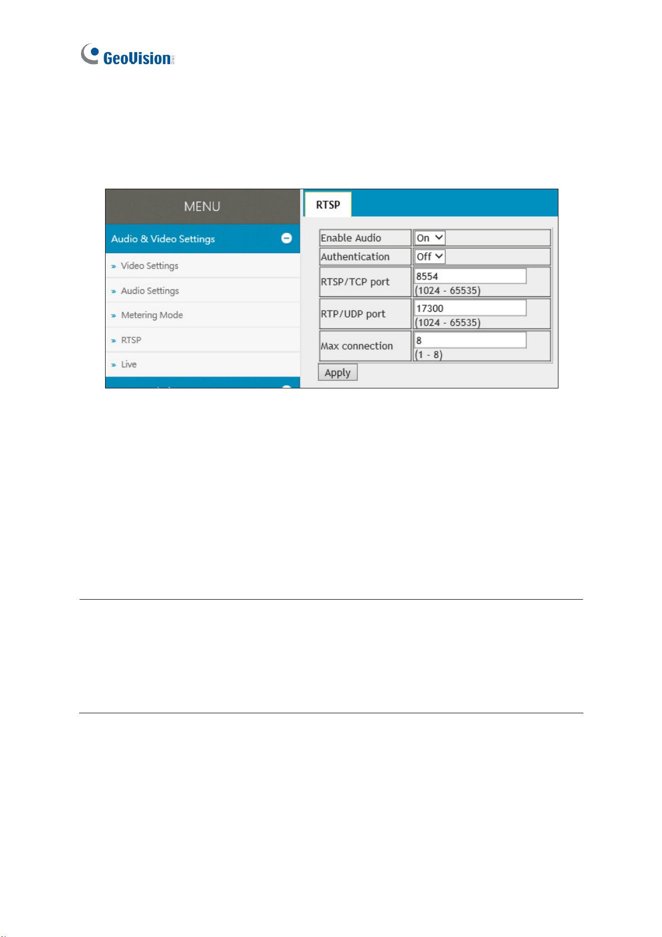
3.1.4 RTSP
Enabled by default, you can modify the RTSP protocol settings to match your network
environment or enable RTSP authentication for improved security.
Figure 3-5
[Enable Audio] Turns audio streaming on or off.
[Authentication] The ID and password of the camera are required to access the camera
through RTSP connections. This function is disabled by default.
[RTSP / TCP Port] Keep the default value or modify it as needed, from 1024 ~ 65535.
[RTP / UDP Port] Keep the default value or modify it as needed, from 1024 ~ 65335.
[Max Connection] Set the maximum number of RTSP connections to the camera, from 1 ~ 8.
Note:
1. When the GV-VR360 is connected to a video management software and/or app,
changing its RTSP settings may result in temporary disconnection or image freeze,
for about 40 ~ 60 seconds
2. For RTSP commands of GV-VR360, see Appendix A.
3.1.5 Live
You can enable live streaming of the camera’s image through YouTube. For details, see
Chapter 4 YouTube Live Stream.
Administrator Mode
20
3
3.2 Events and Alerts
The Administrator can set up triggered actions, of either sending a snapshot by e-mail and/or
activate an output device upon input events.
For the abovementioned triggered actions, you must also configure the following settings:
Input Settings (See 3.2.1.1 Input Settings)
E-mail (See 3.2.2 E-mail)
3.2.1 I/O Control
After installing the I/O devices, you need to enable the I/O settings on the camera. For
connecting I/O devices to the camera, see 1.3 Overview.
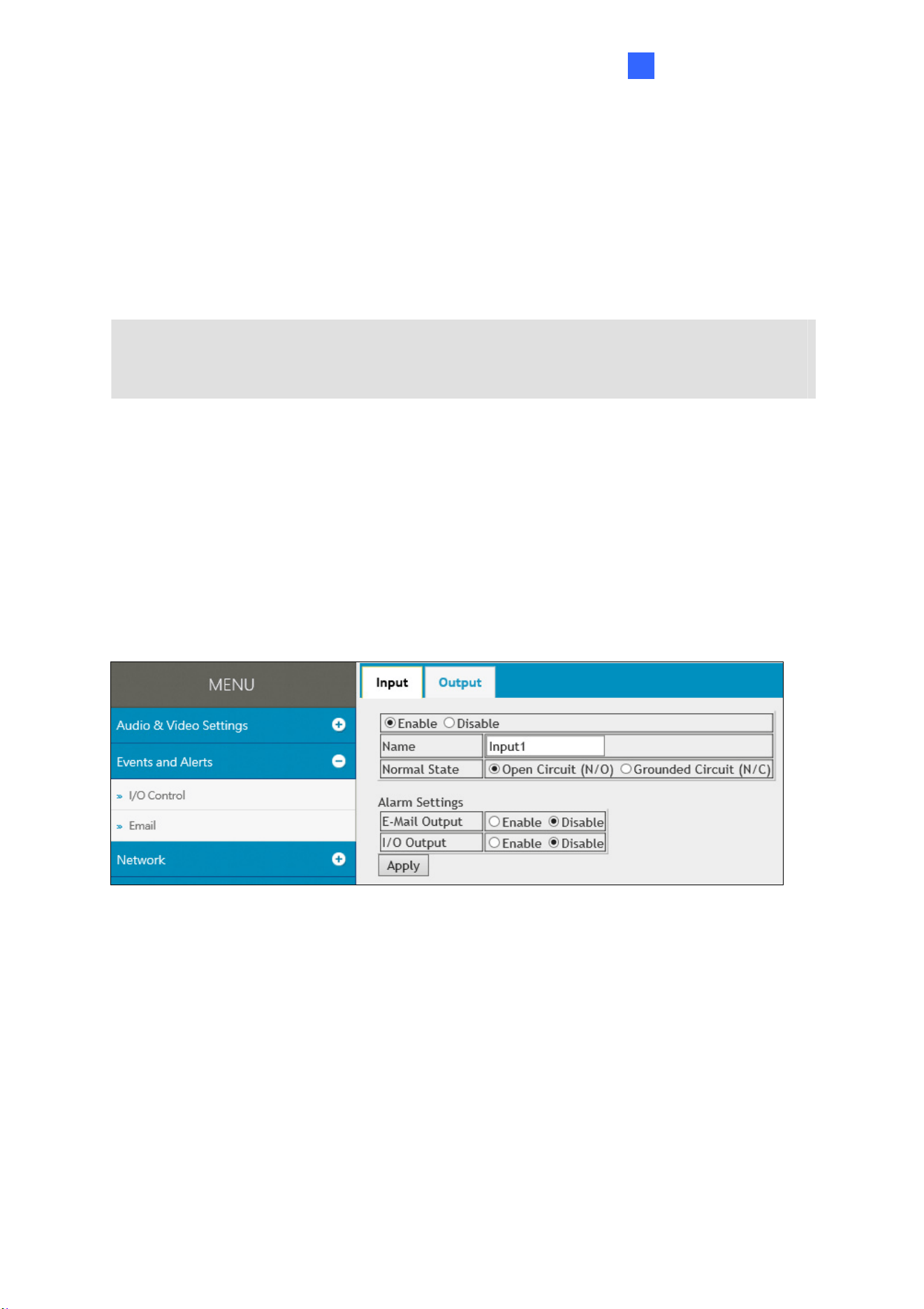
3.2.1.1 Input Settings
To activate the sensor input, select Enable.
Figure 3-6
Name: Type a desired name for the input.
Normal State: Select the initial state of the sensor input between Open Circuit (N/O) /
Grounded Circuit (N/C).
E-Mail Output: Enable this option to send alerts to the e-mail address specified upon
input events. See 3.2.2 E-mail to set up the e-mail server.
I/O Output: Enable this option to trigger the output device upon input events. See 3.2.1.2
Output Settings to set up the output device.
21
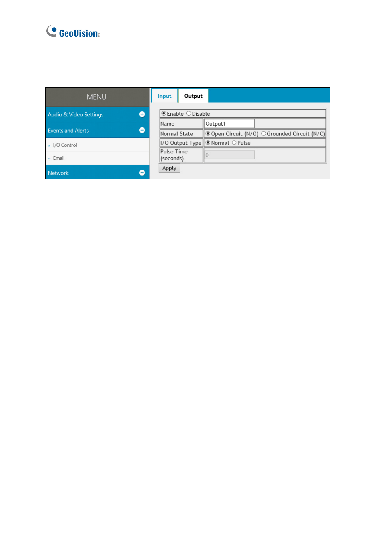
3.2.1.2 Output Settings
Select Enable to activate the output device.
Figure 3-7
Name: Type a desired name for the output.
Normal State: Select the output signal that best suits your device between Open Circuit
(N/O) / Grounded Circuit (N/C).
I/O Output Type: Select Normal for the output to remain in effect until the trigger action
stops or select Pulse for the output to last only for the amount of time specified in the
Pulse Time (seconds) field.
Administrator Mode
22
3
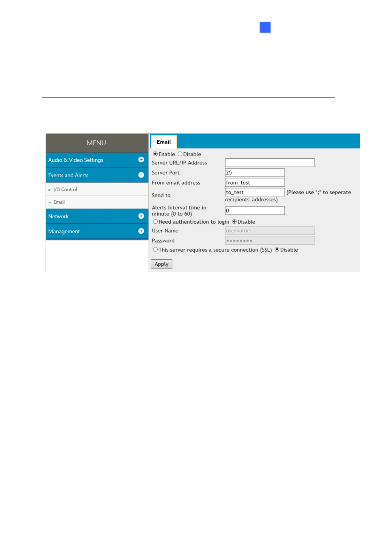
3.2.2 E-mail
You can set up e-mail address(es) for receiving e-mail notifications upon input triggers.
Note: To send e-mail alerts upon input events, be sure to configure the input settings. See
3.2.1.1 Input Settings.
Figure 3-8
To configure the e-mail settings:
1. Select Enable to set up e-mail notifications.
2. Server URL/IP Address: Type the server’s URL or IP address.
3. Server Port: Keep the default port value 25 or modify as needed.
4. From email address: Type the e-mail address to send the notifications from.
5. Send to: Type the e-mail address(s) to send the notifications to.
6. Alerts interval time in minute: Specify the time interval between each e-mail alerts,
from 0 to 60 minutes. Any trigger events during the interval period will be ignored.
7. If the server needs authentication, select Need authentication to login and type a
valid User Name and Password to log in to the server. If the server needs a secure
connection (SSL), select This server requires a secure connection.
8. Click Apply to save the settings.
23
3.3 Network
The Network settings includes some basic but important network configurations that enable
the GV-VR360 to be connected to a TCP/IP network.
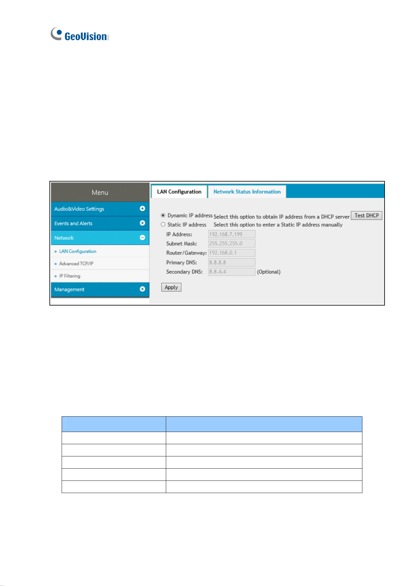
3.3.1 LAN Configuration
Select between Static IP address and Dynamic IP address according to your network
environment.
Figure 3-9
[LAN Configuration]
Dynamic IP address: Select if your network environment has a DHCP server that
automatically assigns a dynamic IP address to the camera. Click Test DHCP to see the IP
address assigned or look up the address using GV-IP Device Utility.
Static IP address: Assign a static, or fixed, IP to the camera. Type the camera’s IP
address, Subnet Mask, Router / Gateway and Primary and Secondary DNS server.
Parameters Default
IP address 192.168.0.10
Subnet Mask 255.255.248.0
Router / Gateway 192.168.0.1
Primary DNS 8.8.8.8
Secondary DNS 168.95.1.1
For details on Dynamic DNS Server Settings, see 3.3.2 Advanced TCP/IP.

Administrator Mode
24
3
[Network Status Information]
In this tab, you can view the network status of the camera.
Figure 3-10
3.3.2 Advanced TCP/IP
Advanced TCP/IP includes the settings of DDNS Server, HTTP port and HTTPS port.
Figure 3-11
[DDNS]
DDNS (Dynamic Domain Name System) provides a convenient way of accessing the camera
when using a dynamic IP. DDNS assigns a domain name to the GV-VR360 for connection
without the need of checking if the IP address assigned by DHCP Server or ISP (in xDSL
connection) has changed.

25
Before enabling the DDNS function, the Administrator can apply for a Host Name from the
DDNS service provider’s website. There are 2 providers listed for GV-VR360: GeoVision
GVDIP or DynDNS.org.
Note: Before using the DDNS function, make sure port mapping, of HTTP and RTSP ports,
is set between the GV-VR360 and your router.
To enable the DDNS function:
1. Select Enable.
2. Select the DDNS service provider registered. If you do not have a DDNS provider, you
can click Register GeoVision DDNS Server to register for the service via GeoVision
DDNS V2 and obtain a host name.
Figure 3-12
3. Type the Host Name used to link to the GV-VR360. For users of GeoVision DDNS Server,
the system will detect for the host name automatically.
4. Type the User Name and Password used to enable the service from the DDNS server.
Depending on the service provider, you may need to add the domain name
(.dipmap.com, .gvdip.com or .org) after your user name, e.g. alice.dipmap.com
5. Click Apply to save the settings.
Administrator Mode
26
3
[HTTP]
The HTTP port enables the GV-VR360 to be connected to the Web. For security purposes,
the Administrator can hide the server from the general HTTP by changing the default port 80
to a different value within the range of 1025 ~ 65535.
[HTTPS]
By enabling the HTTPS (Hypertext Transfer Protocol Secure) settings, you can access the
camera through a secure protocol. To do so, select Enable and set a desired port value, from
1025 ~ 65535.
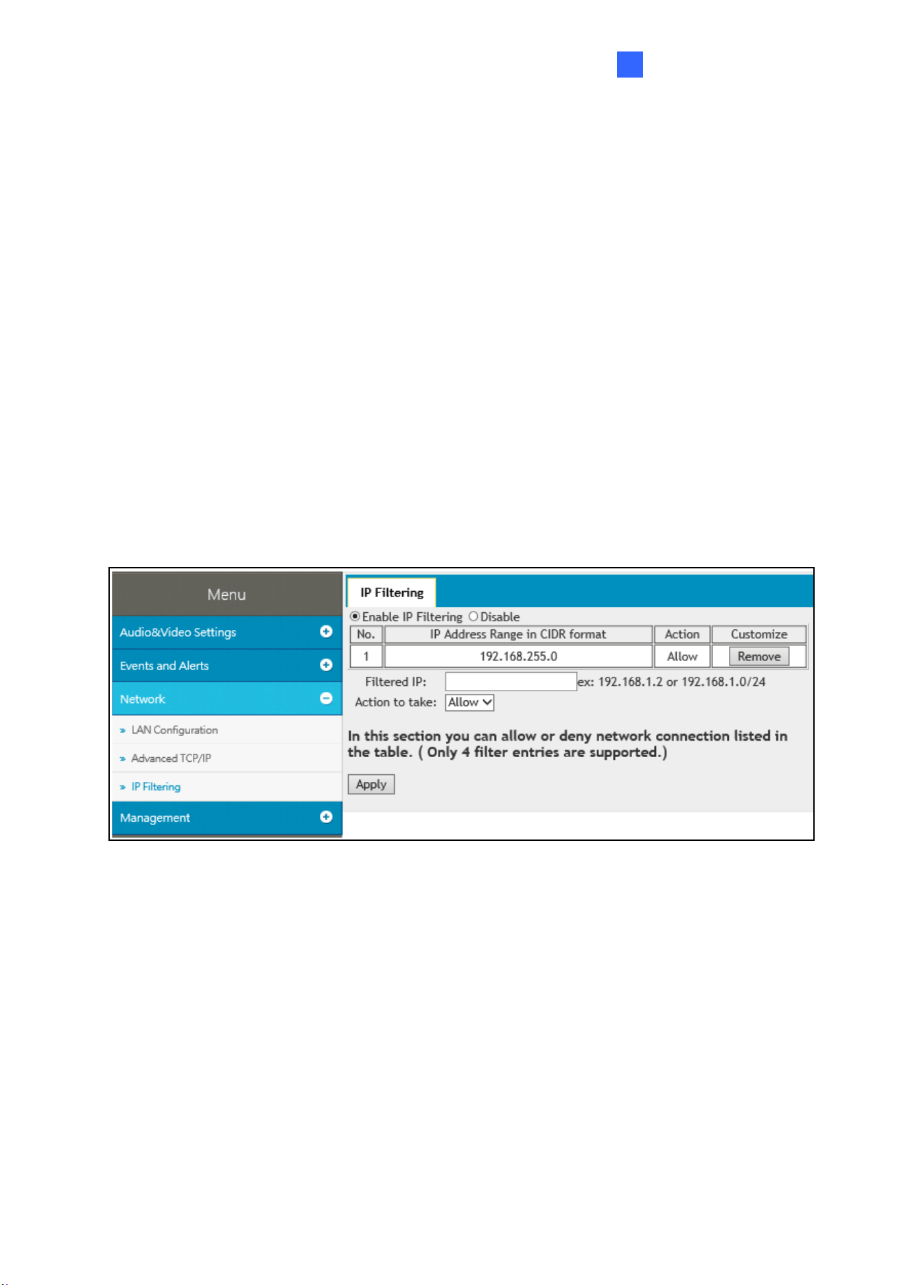
3.3.3 IP Filter
The Administrator can set IP filtering to grant or restrict access to the camera.
Figure 3-13
To enable the IP Filter function:
1. Select Enable IP Filtering.
2. Filtered IP: Type the IP address you want to grant or restrict access to.
3. Action to take: Select the action of Allow or Deny to be taken for the IP address
specified.
4. Click Apply to save the IP address specified.
5. Repeat Step 2 ~ 4 to filter for multiple IP address(es). Up to 4 IP addresses can be filtered
for GV-VR360.
27
3.4 Management
Management section includes settings of the camera, such as date and time, user account
and system log. You can also view the firmware version and execute certain system
operations.
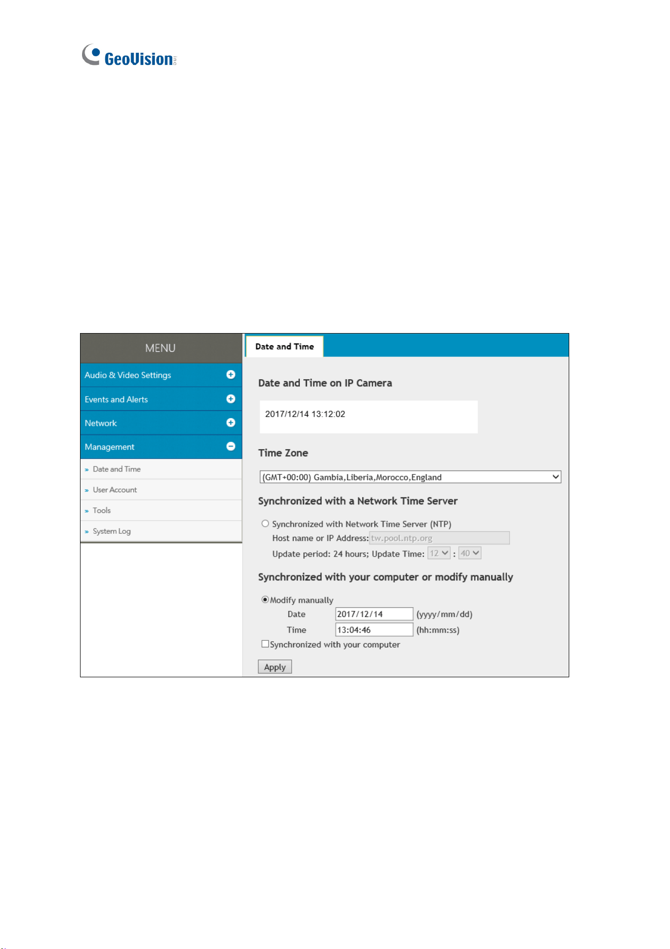
3.4.1 Date and Time
The date and time settings are used to set the time of the GV-VR360.
Figure 3-14
[Date & Time on IP Camera] Displays the current date and time of the camera.
[Time Zone] Sets the time zone for the camera.
[Synchronized with a Network Time Server] By default, the camera uses the
tw.pool.ntp.org timeserver to automatically update its internal clock every 24 hours. Modify the
Host name or IP Address to set the timeserver preferred. To change Update period, the
time in which the camera performs automatic daily updates, use the hour and minute
drop-down lists next to it.
Administrator Mode
28
3
[Synchronized with your computer or modify manually] Manually changes the camera’s
date and time or select Synchronized with your computer to synchronize the camera’s date
and time with those of the local PC.
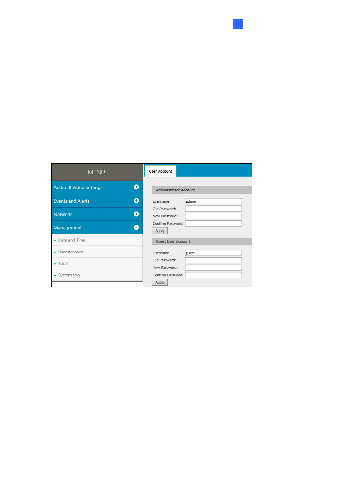
3.4.2 User Account
You can change the login name and password of the Administrator and Guest accounts.
The default Username and Password for the Administrator account are admin.
The default Username and Password for the Guest account are guest.
Figure 3-15
29
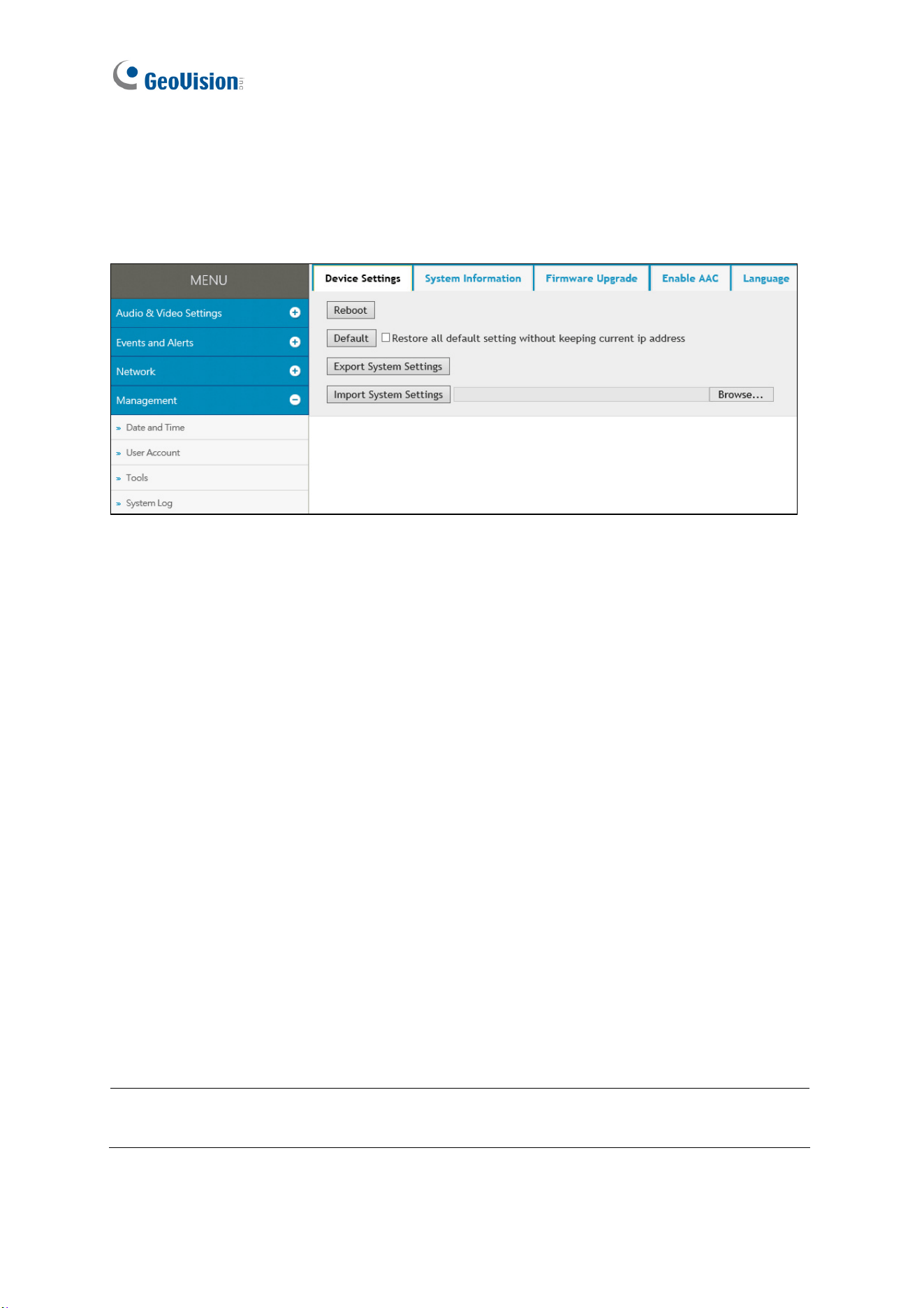
3.4.3 Tools
The Tools settings allows you to execute certain system operations, such as firmware
upgrades, restore default settings and change the language of the Web interface.
Figure 3-16
[Device Settings] You can reboot the GV-VR360, restore it back to its factory default settings
or import / export the system settings.
Reboot: Click Reboot for the camera to restart.
Default: Click Default to restore the camera back to its factory default settings.
Export System Settings: Click to export the configurations of the camera to the local PC.
Import System Settings: Click Browse to locate the system file (.config) previously
saved on the local PC and click Import System Settings to load it to the camera. Log in
again after the import is completed.
[System Information] Displays the firmware version and serial number of the camera.
[Firmware Upgrade] Upgrade the firmware of the camera over the Internet. For details, see
6.1 Upgrading System Firmware.
[Enable AAC] Type the Private Key of the optional ACC audio format and click Upload
Private Key to active its audio support for the GV-VR360.
Note: Audio support for the ACC codec is an optional, paid service. Contact GeoVision
sales representatives for details and a Private Key will be provided upon purchase.
[Language] Select the desired language for the Web interface and click Apply.

Administrator Mode
30
3
3.4.4 System Log
The system log contains dump data required for problem diagnosis by service personnel.
Clear: Click Clear to delete all system logs.
Download: Click Download to download all system logs to the local computer.
31
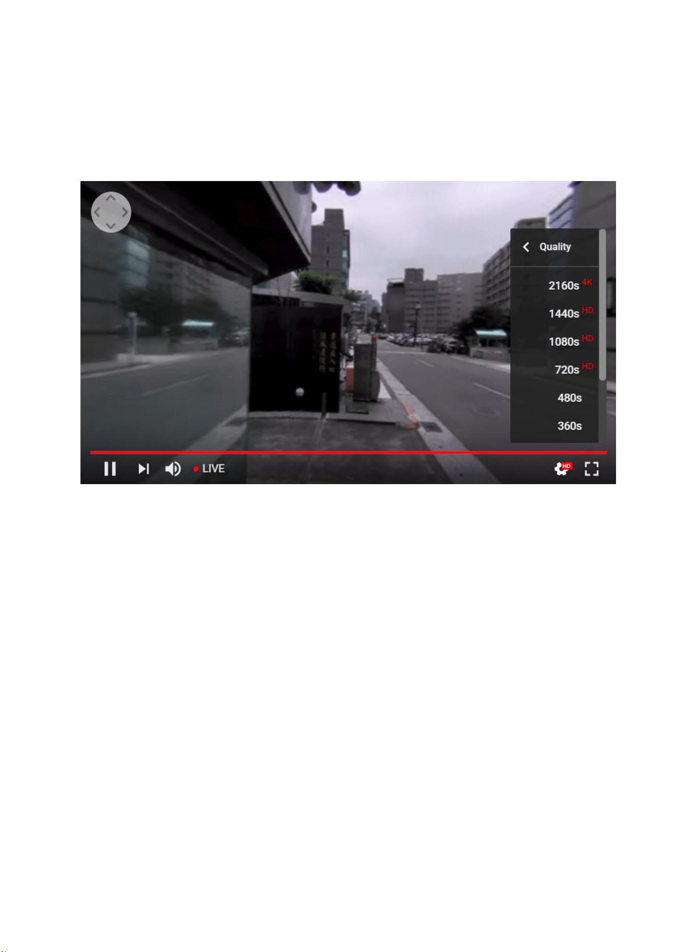
Chapter 4 YouTube Live Stream
GV-VR360 can be streamed online, through YouTube, for a 360° live VR video that can be
viewed by the user and/or viewers with granted access.
Figure 4-1
To set up the live stream of GV-VR360 over YouTube, refer to the related settings below:
Step 1 Obtaining Stream Name & Server
To obtain a live stream name and server from YouTube see 4.1 Setting YouTube Live Stream.
Step 2 Configuring Live Stream Settings
To configure the camera to be readily streamed through YouTube, see 4.2 Configuring Live
Stream Settings.
Step 3 Starting Live Stream
To start live streaming after all the required settings have been set, see 4.3 Starting Live
Stream.
YouTube Live Stream
32
4
4.1 Setting YouTube Live Stream
Before setting up a live stream, you need to have a YouTube account and complete the
required settings to obtain the stream name and RTMP server URL. To do so, log in to your
YouTube account and follow the steps below.
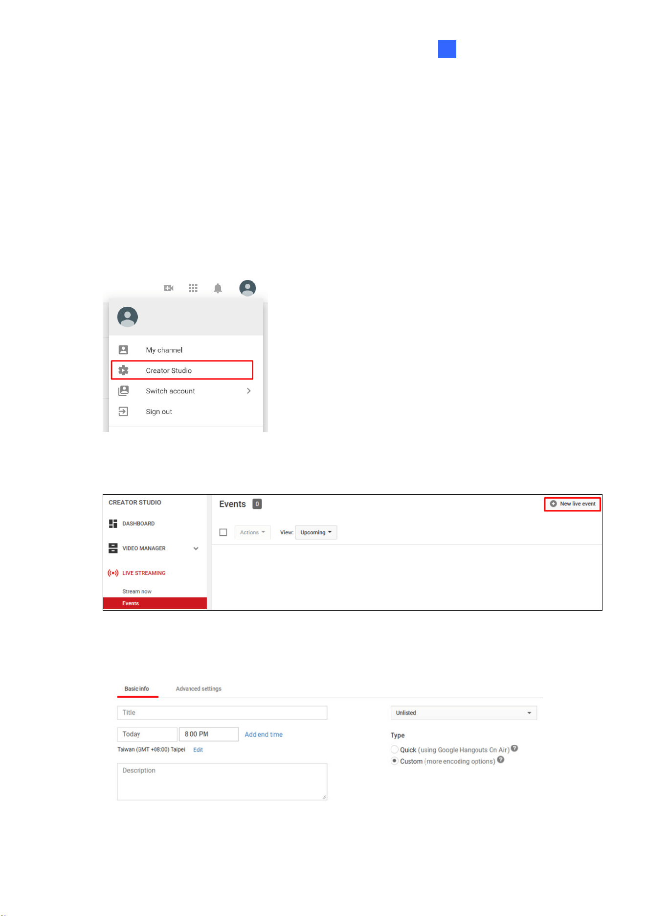
1. After logging in to your YouTube account, click your Account icon and select Creator
Studio.
Figure 4-2
2. Under Creator Studio, click LIVE STREAMING, Events and click New live event.
Figure 4-3
3. Type the information of your live stream as needed.
Figure 4-4
33
A. Name the live stream.
B. Set the start time of your live stream and Add end time if necessary.
C. In the upper-right drop-down list, select between Unlisted and Public, for the
stream to be viewable only by you or open to the public.
D. Select Custom under Type.
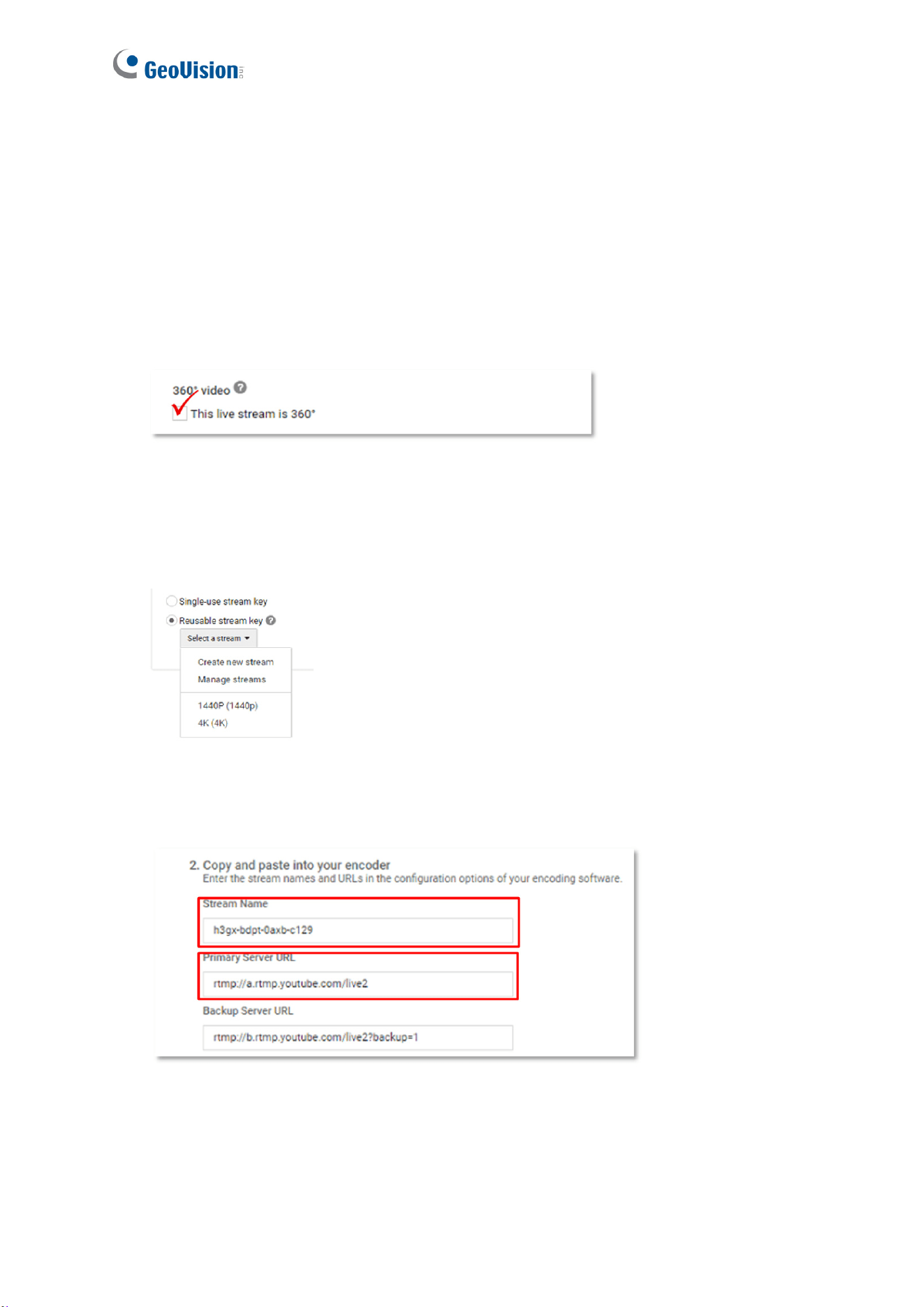
4. Go to the Advanced settings tab and select This live stream is 360°.
Figure 4-5
5. Go to Ingestion Settings and select between Single-use and Reusable stream key.
Reusable stream key is recommended as you do not need to modify the Stream name
when using the same stream for future use.
Figure 4-6
6. Click Save Changes. The Stream Name and Server URL are now available for use.
Figure 4-7
YouTube Live Stream
34
4
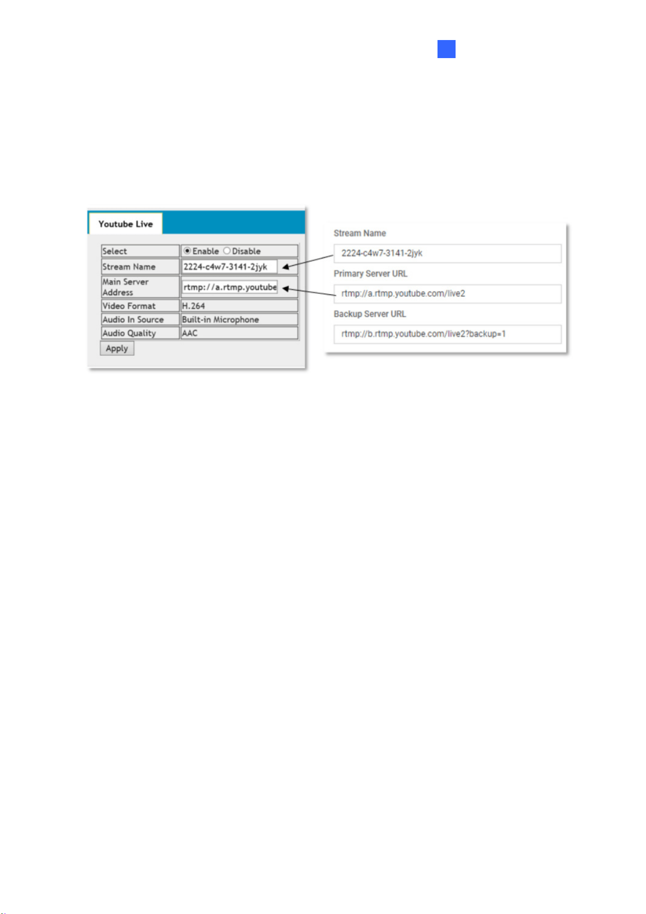
4.2 Configuring Live Stream Settings
Once your YouTube live stream event is set, go to the camera’s Web interface, click System
Settings, Audio & Video Settings and select Live to configure its live stream settings.
Figure 4-8
Stream Name: Copy the Stream name obtained from YouTube (Figure 4-7).
Main Server Address: Copy the server URL obtained from YouTube (Figure 4-7).
Video Format: Displays the current video codec of the camera’s live stream. Only H.264
video codec is supported for YouTube streaming. To change the video codec, see 3.1.1
Video Settings.
Audio In Source & Audio Quality: Displays the current audio source and the audio
codec setting of the camera. Only AAC audio codec is supported for YouTube streaming.
To modify the audio settings, see 3.1.2 Audio Settings.
Click Apply to save the settings.
35
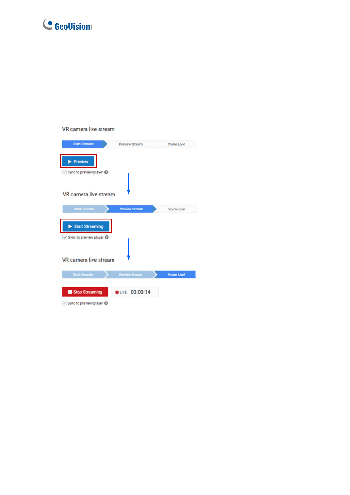
4.3 Starting Live Stream
After the required settings are set, go back to the YouTube website and select Live control
room.
Click Preview and click Start Streaming.
Figure 4-9
The live video stream of GV-VR360 is now viewable on YouTube.
36
Chapter 5 Smart Device Connection
You can access the live video stream of GV-VR360 and view it in VR mode through mobile
devices using the mobile application GV-Eye. YouTube mobile app is also supported.
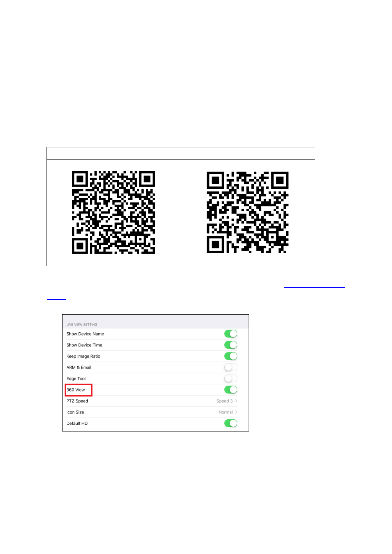
Download GV-Eye from Google Play or Apple Store.
GV-Eye on Google Play GV-Eye on Apple Store
For details on system requirements, installation and setup, please refer to GV-Eye Installation
Guide. To view the live stream in VR mode, enable 360 View in System Settings.
Figure 5-1
37
Chapter 6 Advanced Applications
This chapter introduces advanced applications.
6.1 Upgrading System Firmware
GeoVision periodically updates the latest firmware to the company website. You can update
the camera’s firmware through the Web interface or GV-IP Device Utility.
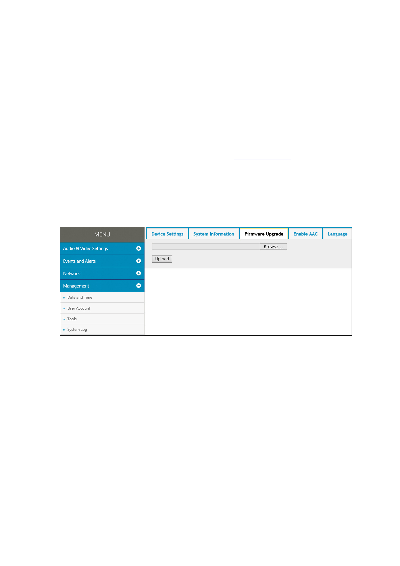
6.1.1 Using the Web Interface
1. Go to System Settings, click Tools Under Management and select Firmware Upgrade.
Figure 6-1
2. Click the Browse button to locate the firmware file (.zip) saved at your local computer.
3. Click the Upload button to start upgrading.

Advanced Applications
38
6
6.1.2 Using the GV-IP Device Utility
The IP Device Utility provides another way to upgrade the firmware. Note the computer used
to upgrade firmware must be under the same network as the camera.
1. Download and install the GV-IP Device Utility from our website
.
2. Double-click the GV-IP Device Utility icon created on your desktop. The Utility window
appears and automatically searches for the IP devices under the same LAN.
Figure 6-2
3. If the camera cannot be found by auto search, click the New button and assign the IP
address to locate the camera on the Internet.
4. Double-click the camera in the list. This dialog box appears.
Figure 6-3
39
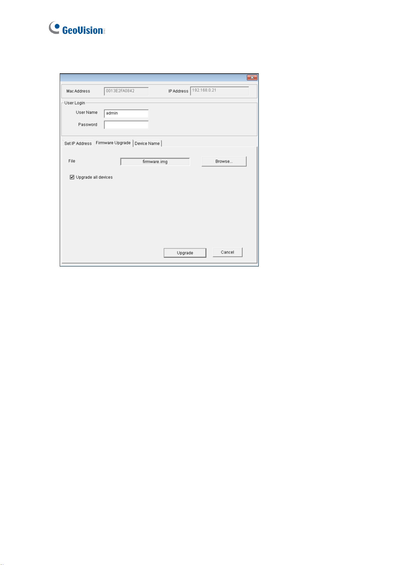
5. Click the Firmware Upgrade tab. This dialog box appears.
Figure 6-4
5. Click the Browse button to locate the firmware file (.zip) saved at your local computer.
6. Type the Password and click Upgrade to start updating.

Advanced Applications
40
6
6.2 Restoring to Factory Default Settings
If for any reason the camera is not responding correctly, you can reset it to its factory default
setting by using the camera’s Web interface or by operating directly on the camera.
6.2.1 Using the Web Interface
1. On the Web interface, go to System Settings.
2. In the left menu of Web interface, select Management and click Tools.
3. Under the Device Settings tab, click Default to restore the camera to its factory default
settings, and the current IP address of the camera will be kept.
4. To restore the camera and its IP address to factory default settings, select Restore all
default setting without keeping current IP address and click Default.
6.2.2 Directly on the Camera
1. Loosen the 3 screws at the rear end of the camera with the supplied torx wrench to reveal
the camera cover. Then loosen the 3 screws on the camera cover to access the default
button.
Figure 6-5
2. Keep the power and network cables (or PoE) connected to the camera.
41
3. Press and hold the Default button on the camera body. This shall take about 5 seconds.
4. Release the Default button. The camera reboots automatically once the process of
loading default settings is completed.
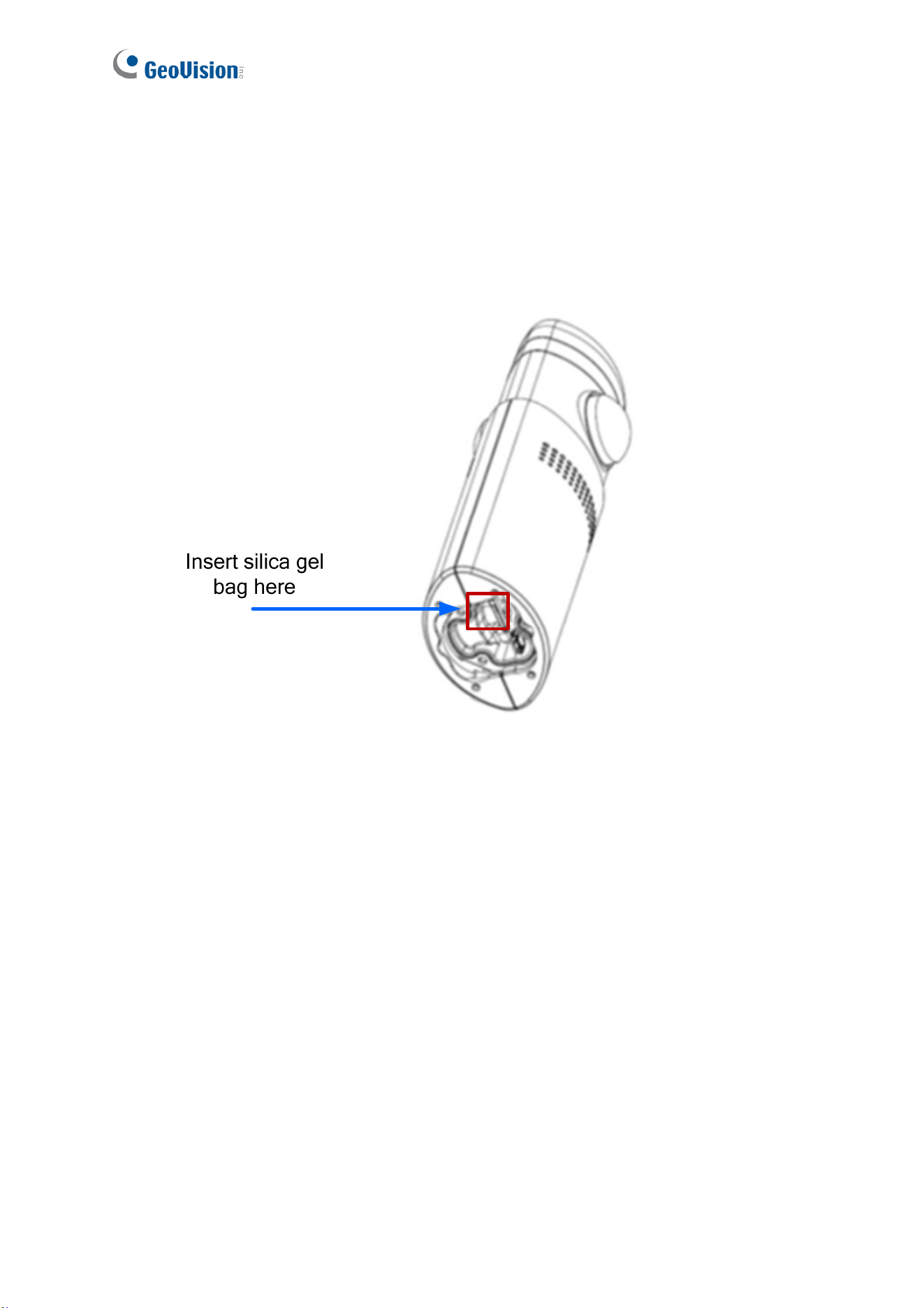
5. Before closing the camera cover, insert the supplied silica gel bag as indicated and push it
in toward the front end of the camera.
Figure 6-5
42
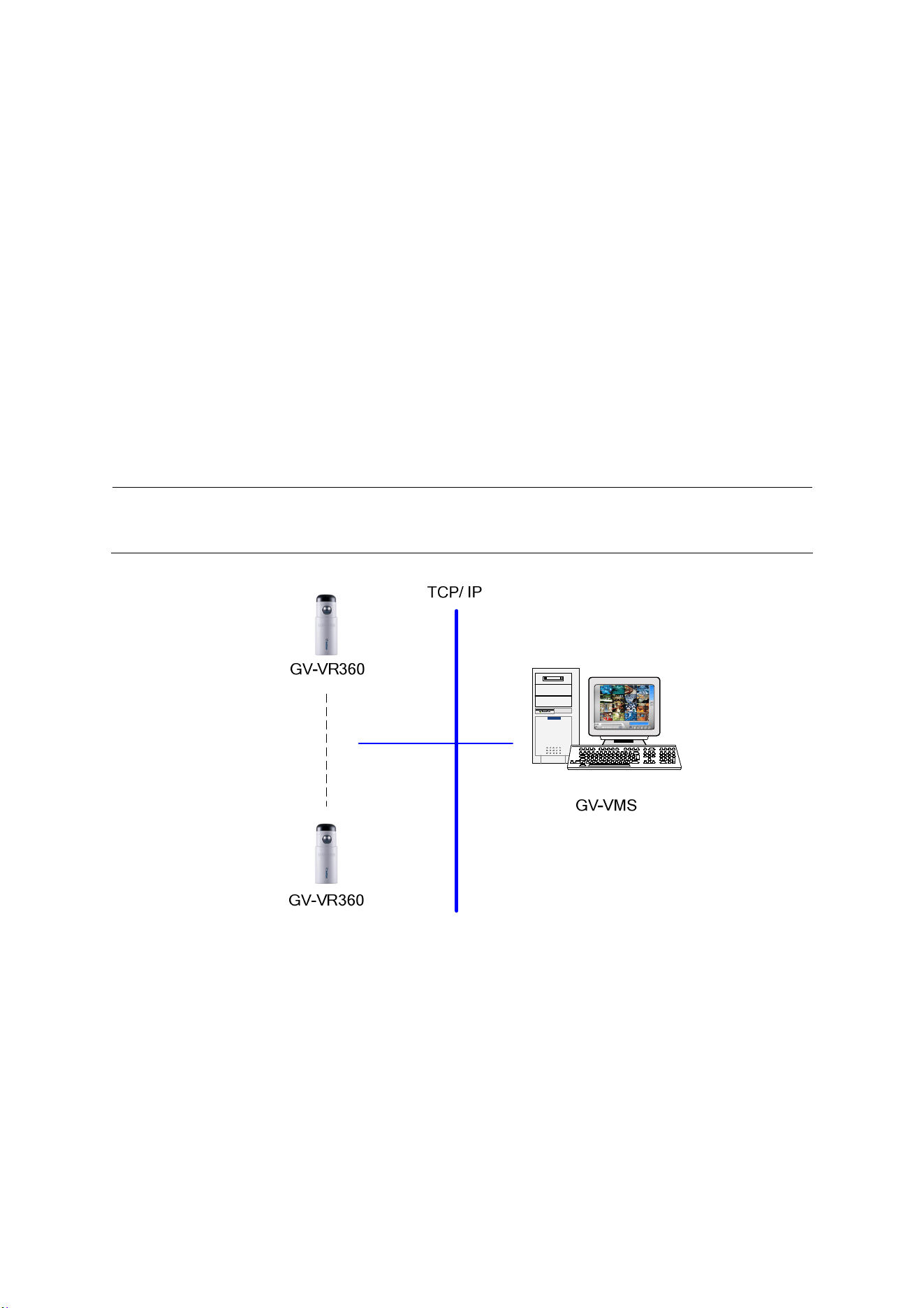
Chapter 7 VMS Configurations
The GV-VMS provide a full range of video management functions and features, such as video
viewing, recording, playback, alert settings and more. The following are the integration
specifications:
GV-VMS version 18.1 or later is required.
GV-VR360 supports up to 8 streams of connection (including RTSP connection).
When a GV-VR360 is connected to IE browser or GeoVision CMS applications, it takes up
1 stream; when it is connected to GV-VMS, it takes up 1 to 2 streams.
Note: By default, GV-VR360 is in single stream and will take up 1 stream when connected
to GV-VMS.
Figure 7-1
43
7.1 Setting Up IP Cameras on GV-VMS
Follow the steps and conform the integration specification below to manually connect your
GV-VR360 to GV-VMS.
Note: The following instructions are based on V17.1 software and user interfaces.
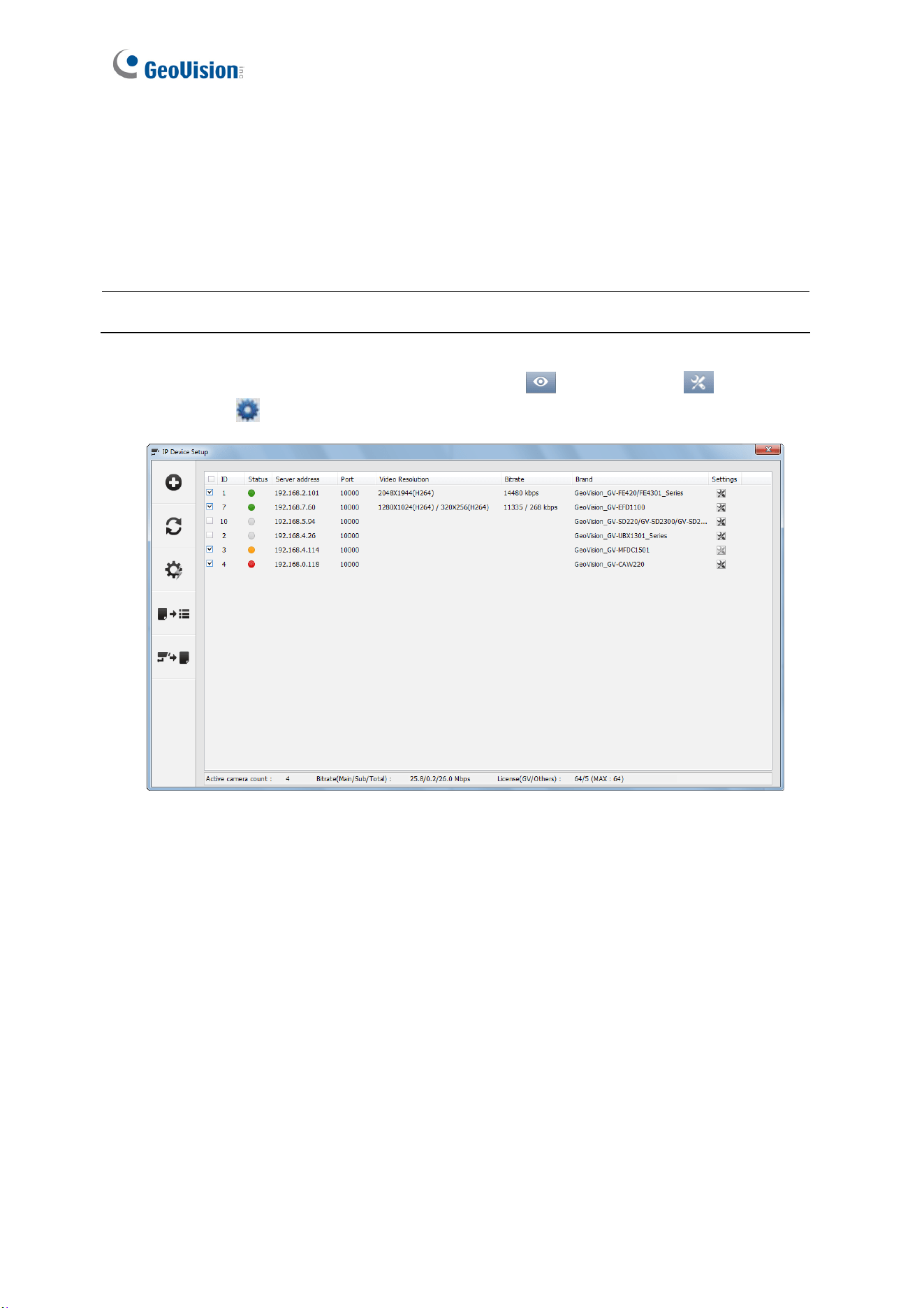
1. To access the IP Device Setup page, click Home
, select Toolbar , click
Configure
and select Camera Install.
Figure 7-2
2. Click Automatic Setup.

VMS Configurations
44
7
3. Double-click GV-VR360 and type the User name and Password of the camera.
Figure 7-3
4. Click OK and this dialog box appears.
Figure 7-4
45
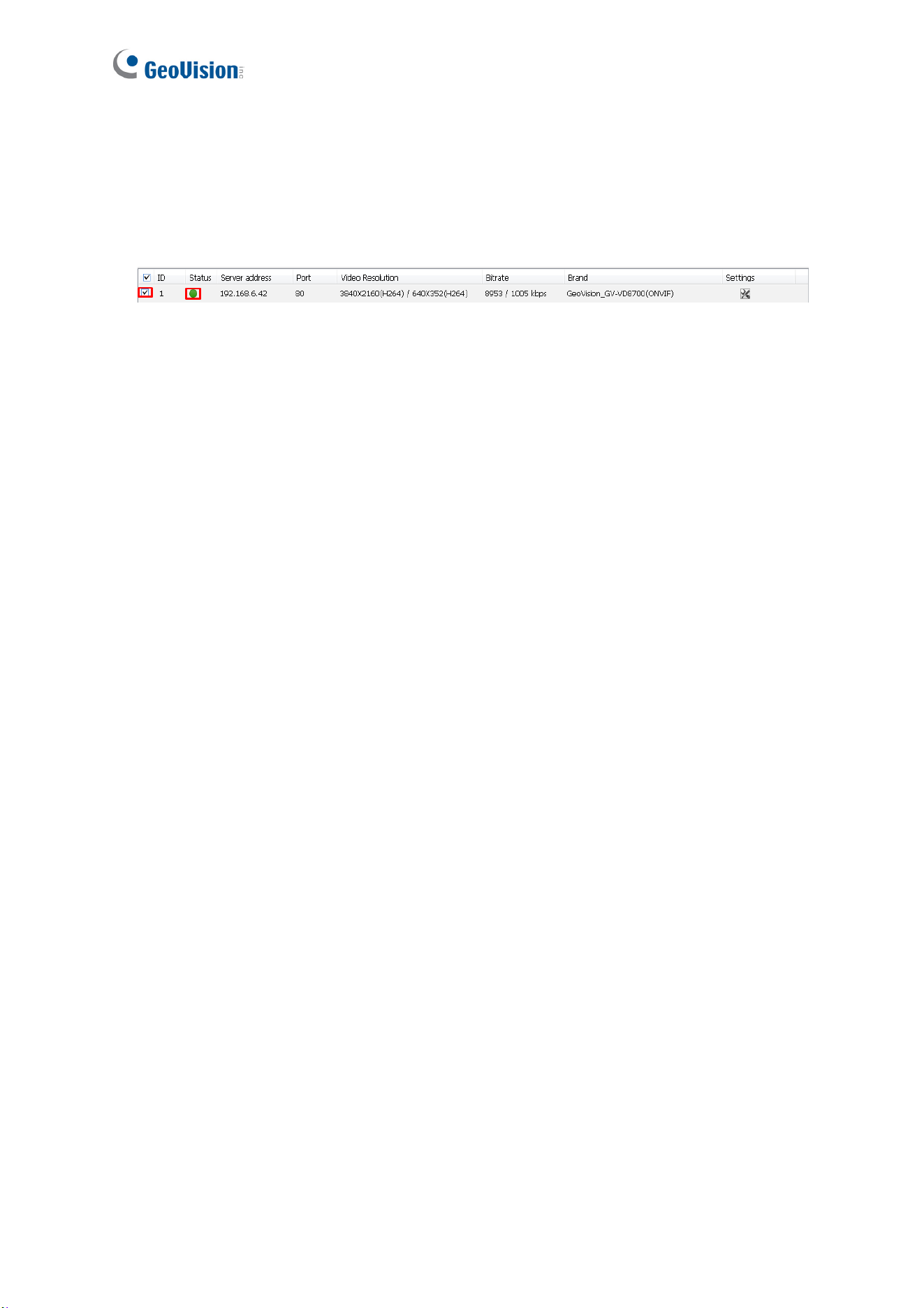
5. Click OK to add the camera to the list.
6. To connect the added camera, click the box besides the ID column. Upon successful
connection, the Status icon shows green, with the video resolution and bit rate being
displayed in the correspondent columns.
Figure 7-5

46
Appendix
A. RTSP Protocol Support
The GV-VR360 supports RTSP protocol for both video and audio streaming. For RTSP
command, enter:
rtsp://<IP of the GV-VR360:8554/<CH No.>.sdp
For example, rtsp://192.168.3.111:8554/CH001.sdp
If RTSP authentication is used, enter:
rtsp://<username>:<password>@<IP of the GV-VR360>:<RTSP port>/<CH No.>.sdp
For example, rtsp://admin.admin@192.168.0.200:8554/CH001.sdp
Note: Only VLC and QuickTime players are supported for streaming video via RTSP
protocol.