

Contents
Copyright, trademarks, and disclaimer 26
Overview 27
What's new?
27
In Management Client 2023 R1 27
Logging in (explained) 28
Login authorization (explained) 29
Log in using a non-secure connection 30
Change your basic user password 30
Product overview 31
System components 32
Management server (explained) 32
SQL Server installations and databases (explained) 32
Recording server (explained) 33
Mobile server (explained) 34
Event server (explained) 35
Log server (explained) 35
API Gateway (explained) 35
Failover 36
XProtect Management Server Failover 36
Failover management server (explained) 36
Failover recording server (explained) 37
Failover recording server functionality (explained) 38
Failover steps (explained) 40
Failover recording server services (explained) 41
Clients 42
Management Client (explained) 42
XProtect Smart Client (explained) 42
XProtect Mobile client (explained) 43
XProtect Web Client (explained) 44
Add-on products 45
Administrator manual | XProtect® VMS 2023 R1
2 | Contents

XProtect Access (explained) 45
XProtect Incident Manager 46
XProtect LPR (explained) 46
XProtect Smart Wall (explained) 47
XProtect Transact (explained) 48
Milestone Open Network Bridge (explained) 49
XProtect DLNA Server (explained) 50
Devices 50
Hardware (explained) 50
Hardware pre-configuration (explained) 51
Devices (explained) 51
Cameras 52
Microphones 52
Speakers 52
Metadata 52
Inputs 53
Outputs 53
Device groups (explained) 53
Media storage 54
Storage and archiving (explained) 54
Archive structure (explained) 59
Pre-buffering and storage of recordings (explained) 60
Storage of the temporary pre-buffer recordings 61
Authentication 61
Active Directory (explained) 61
Users (explained) 61
Windows Users 62
Basic users 62
Identity Provider (explained) 63
External IDP (explained) 63
Claims (explained) 63
Enable users to log in to the XProtect VMS from an external IDP 63
Administrator manual | XProtect® VMS 2023 R1
3 | Contents

Unique user names for external IDP users 63
Example of claims from an external IDP 64
Using sequence number of claim to create user names in XProtect 64
Defining specific claims to create user names in XProtect 65
Deleting external IDP users 65
Security 66
Roles and permissions of a role (explained) 66
Permissions of a role 66
Privacy masking (explained) 67
Privacy masking (explained) 67
Management Client profiles (explained) 69
Smart Client profiles (explained) 69
Evidence locks (explained) 70
Rules and events 72
Rules (explained) 72
Rule complexity 73
Rules and events (explained) 74
Time profiles (explained) 76
Day length time profiles (explained) 76
Notification profiles (explained) 77
Requirements for creating notification profiles 77
User-defined events (explained) 77
Analytics events (explained) 78
Generic events (explained) 79
Alarms 79
Alarms (explained) 79
Alarm configuration 81
Smart map 81
Smart map (explained) 81
Smart map integration with Google Maps (explained) 82
Add digital signature to Maps Static APIkey 82
Smart map integration with Bing Maps (explained) 83
Administrator manual | XProtect® VMS 2023 R1
4 | Contents

Cached smart map files (explained) 83
Architecture 83
A distributed system setup 83
Milestone Interconnect (explained) 84
Selecting Milestone Interconnect or Milestone Federated Architecture (explained) 86
Milestone Interconnect and licensing 86
Milestone Interconnect setups (explained) 86
Configuring Milestone Federated Architecture 87
Ports used by the system 91
Application pools 106
Application pools in Milestone XProtect 106
Working with application pools 107
Open the Application Pools page 107
Product comparison 107
Licensing
108
Licenses (explained)
108
Free XProtect Essential+ 108
Licenses for XProtect VMS products (except XProtect Essential+) 108
License types 109
Base licenses 109
Device licenses 109
Camera licenses for Milestone Interconnect™ 110
Licenses for add-on products 110
License activation (explained) 110
Automatic license activation (explained) 110
Grace period for license activation (explained) 111
Device changes without activation (explained) 111
Calculation of available number of device changes without activation (explained) 112
Milestone Care™ (explained) 113
Licenses and hardware replacement (explained) 113
Get an overview of your licenses 114
Activate your licenses 115
Administrator manual | XProtect® VMS 2023 R1
5 | Contents

Enable automatic license activation 115
Disable automatic license activation 115
Activate licenses online 116
Activate licenses offline 116
Activate licenses after grace period 117
Get additional licenses 117
Change the Software License Code 117
From the management server tray icon 118
From Management Client 118
License Information window 118
Requirements and considerations
122
Daylight saving time (explained)
122
Time servers (explained) 122
Limit size of database 123
IPv6 and IPv4 (explained) 123
Writing IPv6 addresses (explained) 125
Using IPv6 Addresses in URLs 125
Virtual servers 126
Multiple management servers (clustering) (explained) 126
Requirements for clustering 127
Protect recording databases from corruption 127
Hard disk failure: protect your drives 127
Windows Task Manager: be careful when you end processes 128
Power outages: use a UPS 128
SQL database transaction log (explained) 128
Minimum system requirements 129
Before you start installation 129
Prepare your servers and network 129
Prepare Active Directory 130
Installation method 130
Decide on a SQL Server edition 132
Select service account 133
Administrator manual | XProtect® VMS 2023 R1
6 | Contents

Kerberos authentication (explained) 133
Virus scanning exclusions (explained) 135
How can XProtect VMS be configured to run in FIPS 140-2 compliant mode? 136
Before you install XProtect VMS on a FIPS enabled system 137
Register Software License Code 137
Device drivers (explained) 137
Requirements for offline installation 138
Secure communication (explained) 138
Installation
140
Install a new XProtect system
140
Install XProtect Essential+ 140
Install your system - Single computer option 145
Install your system - Custom option 151
Install new XProtect components 156
Installing through Download Manager (explained) 156
Install a Management Client through Download Manager 157
Install a recording server through Download Manager 158
Install a failover recording server through Download Manager 161
Installing XProtect VMS using non-default ports 163
Installing silently through a command line shell (explained) 163
Install a recording server silently 165
Install XProtect Smart Client silently 166
Install a log server silently 167
Installation for workgroups 168
Install in a cluster 169
Use a certificate for an external IDP in a cluster environment 172
Troubleshooting errors when an external IDP configuration is protected with a certificate 173
Download Manager/download web page 174
Download Manager's default configuration 176
Download Manager's standard installers (user) 178
Add/publish Download Manager installer components 178
Hide/remove Download Manager installer components 179
Administrator manual | XProtect® VMS 2023 R1
7 | Contents

Device pack installer - must be downloaded 180
Installation log files and troubleshooting 181
Configuration
182
Initial configuration tasks list
182
Recording servers 183
Change or verify the basic configuration of a recording server 183
Register a recording server 185
View encryption status to clients 186
Specify behavior when recording storage is unavailable 187
Add a new storage 188
Create an archive within a storage 189
Attach a device or group of devices to a storage 189
Disabled devices 189
Edit settings for a selected storage or archive 190
Enable digital signing for export 190
Encrypt your recordings 191
Back up archived recordings 194
Delete an archive from a storage 195
Delete a storage 195
Move non-archived recordings from one storage to another 196
Assign failover recording servers 196
Enable multicasting for the recording server 197
Enable multicasting for individual cameras 198
Define public address and port 198
Assign local IP ranges 199
Filter the device tree 199
Filter the device tree 199
Filter criteria characteristics 199
Specifying multiple filter criteria 200
Resetting the filter 200
Disabled devices 200
Failover servers 200
Administrator manual | XProtect® VMS 2023 R1
8 | Contents

Set up and enable failover recording servers 200
Group failover recording servers for cold standby 201
View encryption status on a failover recording server 201
View status messages 202
View version information 202
Hardware 203
Add hardware 203
Add Hardware (dialog) 203
Disable / enable hardware 205
Edit hardware 205
Edit Hardware (dialog) 205
Enable / disable individual devices 208
Set up a secure connection to the hardware 209
Enable PTZ on a video encoder 210
Change passwords on hardware devices 211
Update firmware on hardware devices 212
Add and configure an external IDP 214
Devices - Groups 214
Add a device group 214
Specify which devices to include in a device group 214
Disabled Devices 215
Specify common properties for all devices in a device group 215
Disabled devices 216
Enable/disable devices via device groups 216
Devices - Camera settings 216
View or edit camera settings 216
Preview 217
Performance 217
Enable and disable fisheye lens support 217
Specify fisheye lens settings 217
Devices - Recording 218
Enable/disable recording 218
Administrator manual | XProtect® VMS 2023 R1
9 | Contents

Enable recording on related devices 218
Manage manual recording 218
Add to roles: 219
Use in rules: 219
Specify recording frame rate 219
Enable keyframe recording 219
Enable recording on related devices 220
Save and retrieve remote recording 220
Delete recordings 221
Devices - Streaming 221
Add a stream 221
Manage multi-streaming 221
To change which stream to use for recording 222
Limit data transmission 222
Examples
222
Devices - Storage
223
Manage pre-buffering 223
Enable and disable pre-buffering 223
Specify storage location and pre-buffer period 223
Use pre-buffer in rules 224
Monitor the status of databases for devices 224
Move devices from one storage to another 226
Devices - Motion detection 226
Motion detection (explained) 226
Image quality 227
Privacy masks 227
Enable and disable motion detection 227
Specify the default setting of motion detection for cameras 227
Enable or disable motion detection for a specific camera 227
Enable or disable hardware acceleration 227
To enable or disable hardware acceleration 227
Use of GPU resources 228
Administrator manual | XProtect® VMS 2023 R1
10 | Contents

Load balancing and performance 228
Enable manual sensitivity to define motion 229
Specify threshold to define motion 229
Specify exclude regions for motion detection 230
Devices - Preset camera positions 231
The Home preset position 231
Add a preset position (type 1) 231
Use preset positions from the camera (type 2) 233
Assign a camera's preset position as default 233
Specify the default preset as the PTZ Home position 234
Enable setting the PTZ home position
234
Edit a preset position for a camera (type 1 only)
234
Rename a preset position for a camera (type 2 only) 236
Test a preset position (type 1 only) 236
Devices - Patrolling 237
Patrolling profiles and manual patrolling (explained) 237
Manual patrolling 237
Add a patrolling profile 237
Specify preset positions in a patrolling profile 238
Specify the time at each preset position 238
Customize transitions (PTZ) 239
Specify an end position when patrolling 240
Reserve and release PTZ sessions 240
Reserve a PTZ session 241
Release a PTZ session 241
Specify PTZ session timeouts 241
Devices - Events for rules 242
Add or delete an event for a device 242
Add an event 242
Delete an event 242
Specify event properties 243
Use several instances of an event 243
Administrator manual | XProtect® VMS 2023 R1
11 | Contents

Devices - Privacy masks 243
Enable/disable privacy masking 243
Define privacy masks 244
Change the timeout for lifted privacy masks 245
Give users permission to lift privacy masks 246
Create a report of your privacy masking configuration 247
Clients 248
View groups (explained) 248
Add a view group 248
Smart Client profiles 249
Add and configure a Smart Client profile 249
Copy a Smart Client profile 249
Create and set up Smart Client profiles, roles and time profiles 249
Set number of cameras allowed during search 250
Change the default export settings 254
Management Client profiles 255
Add and configure a Management Client profile 255
Copy a Management Client profile 256
Manage the visibility of functionality for a Management Client profile 256
Associate a Management Client profile with a role 256
Manage the overall access to system functionality for a role 256
Limit visibility of functionality for a profile 257
Matrix 257
Matrix and Matrix recipients (explained) 257
Define rules sending video to Matrix-recipients 257
Add Matrix recipients 258
Send the same video to several XProtect Smart Client views 258
Rules and events 259
Add rules 259
Events 259
Actions and stop actions 259
Create a rule 259
Administrator manual | XProtect® VMS 2023 R1
12 | Contents

Validate rules 260
Validate a rule 261
Validate all rules 261
Edit, copy and rename a rule 261
Deactivate and activate a rule 262
Specify a time profile 262
Add a single time 262
Add a recurring time 263
Recurring time 264
Edit a time profile 264
Create day length time profiles 265
Day length time profile properties 265
Add notification profiles 265
Trigger email notifications from rules 267
Add a user-defined event 267
Rename a user defined event 268
Add and edit an analytics event 268
Add an analytics event 268
Edit an analytics event 268
Edit analytics events settings 268
Test an analytics event 269
Add a generic event 269
To add a generic event: 270
Authentication 270
Register claims from an external IDP 270
Map claims from an external IDP to roles in XProtect 270
Log in via an external IDP 271
Security 271
Add and manage a role 271
Copy, rename or delete a role 272
Copy a role 272
Rename a role 272
Administrator manual | XProtect® VMS 2023 R1
13 | Contents

Delete a role 272
View effective roles 272
Assign/remove users and groups to/from roles 273
Assign Windows users and groups to a role 273
Assign basic users to a role 273
Remove users and groups from a role 273
Create basic users 274
Configure login settings for basic users 274
To create a basic user on your system: 275
View encryption status to clients 276
System Dashboard 277
View currently ongoing tasks on recording servers 277
System monitor (explained) 278
System monitor dashboard (explained) 278
System monitor thresholds (explained) 278
View the current state of your hardware and troubleshoot if needed 279
View the historical state of your hardware and print a report 279
Collect historical data of hardware states 280
Add a new camera or server tile on the System monitor dashboard 280
Edit a camera or server tile on the System monitor dashboard 281
Delete a camera or server tile on the System monitor dashboard 281
Edit thresholds for when hardware states should change 281
View evidence locks in the system 282
Print a report with your system configuration 282
Metadata 283
Show or hide metadata search categories and search filters 283
Alarms 284
Add an alarm 284
Enable encryption 285
Enable encryption to and from the management server 285
Enable server encryption for recording servers or remote servers 286
Enable event server encryption 288
Administrator manual | XProtect® VMS 2023 R1
14 | Contents

Enable encryption to clients and servers 289
Enable encryption on the mobile server 291
Milestone Federated Architecture 293
Set up your system to run federated sites 293
Add site to hierarchy 295
Accept inclusion in the hierarchy 296
Set site properties 296
Refresh site hierarchy 297
Log into other sites in the hierarchy 297
Update site information of child sites 298
Detach a site from the hierarchy 298
Milestone Interconnect 299
Add a remote site to your central Milestone Interconnect site 299
Assign user permissions 299
Update remote site hardware 300
Enable playback directly from remote site camera 300
Retrieve remote recordings from remote site camera 300
Configure your central site to respond to events from remote sites 301
Remote connect services 303
Remote connect services (explained) 303
Install secure tunnel server environment for One-Click camera connection 303
Add or edit secure tunnel servers 303
Register new Axis One-Click camera 304
Smart maps 304
Geographic backgrounds (explained) 304
Enable Bing Maps or Google Maps in Management Client 306
Enable Bing Maps or Google Maps in XProtect Smart Client 306
Enable Milestone Map Service 306
Specify OpenStreetMap tile server 307
Enable smart map editing 308
Enable editing devices on smart map 309
Define device position and camera direction, field of view, depth (smart map) 310
Administrator manual | XProtect® VMS 2023 R1
15 | Contents

Configure smart map with Milestone Federated Architecture 312
Maintenance
313
Backing up and restoring system configuration
313
Backing up and restoring your system configuration (explained) 313
Select shared backup folder 314
Back up system configuration manually 314
Restore system configuration from a manual backup 314
System configuration password (explained) 315
System configuration password settings 316
Change the system configuration password settings 316
Enter the system configuration password settings (recovery) 317
Manually backing up your system configuration (explained) 318
Backing up and restoring the event server configuration (explained) 318
Scheduled backup and restore of system configuration (explained) 318
Back up system configuration with scheduled backup 319
Restore system configuration from a scheduled backup 319
Back up log server's SQL database 320
Backup and restore fail and problem scenarios (explained) 321
Moving the management server 321
Unavailable management servers (explained) 322
Move the system configuration 322
Replace a recording server 323
Move hardware 324
Move hardware (wizard) 325
Replace hardware 327
Update your hardware data 330
Managing the SQL Server and databases 331
Changing the SQL Server and database addresses (explained) 331
Change the log server's SQL Server and database 331
Change the management server and the event server's SQL Server and database 331
Change the XProtect Incident Manager server's SQL Server and database 332
Change the IDP server's SQL Server and database 332
Administrator manual | XProtect® VMS 2023 R1
16 | Contents

Managing server services 333
Server manager tray icons (explained) 333
Start or stop the Management Server service 335
Start or stop the Recording Server service 336
View status messages for Management Server or Recording Server 337
Manage encryption with the Server Configurator 337
Start, stop, or restart the Event Server service 337
Stopping the Event Server service 338
View Event Server or MIP logs 338
Enter current system configuration password 340
Managing registered services 340
Add and edit registered services 341
Manage network configuration 341
Registered services properties 341
Removing device drivers (explained) 342
Remove a recording server 343
Delete all hardware on a recording server 343
Changing the host name of the management server computer 343
The validity of certificates 343
Loss of customer data properties for registered services 344
In Milestone Customer Dashboard, the host name will appear unchanged 344
A host name change can trigger the change of the SQL Server address 344
Host name changes in a Milestone Federated Architecture 345
The host of the site is the root node in the architecture 345
The host of the site is a child node in the architecture 345
Managing server logs 346
Identify user activity, events, actions and errors 346
Filter Logs 346
Export logs 348
Search logs 348
Change log language 349
Allow 2018 R2 and earlier components to write logs 349
Administrator manual | XProtect® VMS 2023 R1
17 | Contents

Troubleshooting 350
Debug logs (explained)
350
Issue: Change of SQL Server and database addresses prevents database access 350
Issue: Recording server startup fails due to port conflict 351
Issue: Recording Server goes offline when switching Management Server cluster node 352
Issue: A parent node in a Milestone Federated Architecture setup cannot connect to a child node 353
To reestablish the connection between parent node and site 353
Upgrade
354
Upgrade (explained)
354
Upgrade requirements 355
Upgrade XProtect VMS to run in FIPS 140-2 compliant mode 356
Upgrade best practices 357
Upgrade in a cluster 359
User interface details
361
Main window and panes
361
Panes layout 363
System settings (Options dialog box) 365
General tab (options) 366
Server Logs tab (options) 369
Mail Server tab (options) 370
AVI Generation tab (options) 371
Network tab (options) 372
Bookmark tab (options) 372
User Settings tab (options) 372
External IDP tab (options) 372
Configure an external IDP 373
Register claims 374
Add redirect URIs for the web clients 375
Customer Dashboard tab (options) 376
Evidence Lock tab (options) 376
Audio messages tab (options) 377
Privacy settings tab 378
Administrator manual | XProtect® VMS 2023 R1
18 | Contents

Access Control Settings tab (options) 378
Analytics Events tab (options) 378
Alarms and Events tab (options) 379
Generic Events tab (options) 381
Component menus 383
Management Client menus 383
File menu 383
Edit menu 383
View menu 383
Action menu 384
Tools menu 384
Help menu 385
Server Configurator (Utility) 385
Encryption tab properties 385
Registering servers 386
Language selection 387
Tray icon status 387
Starting and stopping services from tray icons 389
Management Server Manager (tray icon) 390
Basics node 391
License Information (Basics node) 391
Site Information (Basics node) 391
Remote Connect Services node 392
Axis One-click Camera Connection (Remote Connect Services node) 392
Servers node 393
Servers (node) 393
Recording Servers (Servers node) 393
Recording Server Settings window 394
Recording servers properties 395
Storage tab (recording server) 397
Failover tab (recording server) 401
Multicast tab (recording server) 403
Administrator manual | XProtect® VMS 2023 R1
19 | Contents

Network tab (recording server) 406
Failover Servers (Servers node) 406
Info tab properties (failover server) 408
Multicast tab (failover server) 410
Info tab properties (failover group) 410
Sequence tab properties (failover group) 411
Remote server for Milestone Interconnect 411
Info tab (remote server) 411
Settings tab (remote server) 412
Events tab (remote server) 412
Remote Retrieval tab 412
Devices node 413
Devices (Devices node) 413
Status icons of devices 414
Cameras (Devices node) 416
Microphones (Devices node) 417
Speakers (Devices node) 417
Metadata (Devices node) 418
Input (Devices node) 418
Output (Devices node) 418
Devices tabs 419
Info tab (devices) 419
Info tab properties 420
Settings tab (devices) 421
Streams tab (devices) 422
Tasks on the Streams tab 423
Record tab (devices) 424
Tasks on the Record tab 426
Motion tab (devices) 426
Tasks on the Motion tab 427
Presets tab (devices) 429
Tasks on the Presets tab 431
Administrator manual | XProtect® VMS 2023 R1
20 | Contents

PTZ session properties 432
Patrolling tab (devices) 433
Tasks on the Patrolling tab 435
Manual patrolling properties 435
Fisheye lens tab (devices) 436
Task on the Fisheye lens tab 436
Events tab (devices) 437
Tasks on the Events tab 437
Event tab (properties) 438
Client tab (devices) 438
Client tab properties 439
Privacy masking tab (devices) 441
Tasks on the Privacy masking tab 442
Tasks related to Privacy masking 442
Privacy masking tab (properties) 442
Hardware Properties window 444
Info tab (hardware) 444
Settings tab (hardware) 445
PTZ tab (video encoders) 446
Client node 446
Clients (node) 446
Smart Wall (Client node) 447
Smart Wall properties 447
Monitor properties 448
Smart Client Profiles (Client node) 450
Info tab (Smart Client profiles) 450
General tab (Smart Client profiles) 451
Advanced tab (Smart Client profiles) 451
Live tab (Smart Client profiles) 452
Playback tab (Smart Client profiles) 452
Setup tab (Smart Client profiles) 453
Export tab (Smart Client profiles) 453
Administrator manual | XProtect® VMS 2023 R1
21 | Contents

Timeline tab (Smart Client profiles) 453
Access Control tab (Smart Client profiles) 454
Alarm Manager tab (Smart Client profiles) 454
Smart map tab (Smart Client profiles) 455
View Layout tab (Smart Client profiles) 456
Management Client Profiles (Client node) 456
Info tab (Management Client Profiles) 456
Profile tab (Management Client Profiles) 456
Navigation 457
Details 458
Tools Menu 458
Federated Sites 459
Rules and Events node 459
Rules (Rules and Events node) 459
Recreate default rules 460
Notification Profiles (Rules and Events node) 462
Events overview 463
Hardware: 463
Hardware - Configurable events: 463
Hardware - Predefined events: 464
Devices - Configurable events: 464
Devices - Predefined events: 464
External events - Predefined events: 467
External events - Generic events: 468
External events - User-defined events: 468
Recording servers: 468
System monitor events 470
System Monitor - Server: 470
System Monitor - Camera: 472
System Monitor - Disk: 473
System Monitor - Storage: 473
Other: 474
Administrator manual | XProtect® VMS 2023 R1
22 | Contents

Events from add-on products and integrations: 474
Actions and stop actions 474
Manage Rule Wizard 474
Test Analytics Event (properties) 486
Generic Events and Data sources (properties) 488
Generic event (properties) 488
Generic event data source (properties) 490
Webhooks (Rules and Events node) 492
Security node 492
Roles (Security node) 492
Info tab (roles) 492
User and Groups tab (roles) 494
External IDP (roles) 494
Overall Security tab (roles) 495
Device tab (roles) 523
Camera-related permissions 524
Microphone-related permissions 525
Speaker-related permissions 527
Metadata-related permissions 529
Input-related permissions 530
Output-related permissions 530
PTZ tab (roles) 531
Speech tab (roles) 532
Remote Recordings tab (roles) 533
Smart Wall tab (roles) 533
External Event tab (roles) 533
View Group tab (roles) 534
Servers tab (roles) 534
Matrix tab (roles) 535
Alarms tab (roles) 535
Access Control tab (roles) 536
LPR tab (roles) 536
Administrator manual | XProtect® VMS 2023 R1
23 | Contents

Incidents tab (roles) 537
MIP tab (roles) 537
Basic user (Security node) 537
System dashboard node 538
System Dashboard node 538
Current Tasks (System Dashboard node) 538
System Monitor (System Dashboard node) 538
System monitor dashboard window 539
Tiles 539
Hardware list with monitoring parameters 539
Customize dashboard window 539
Details window 539
System Monitor Thresholds (System Dashboard node) 541
Evidence Lock (System Dashboard node) 544
Configuration Reports (System Dashboard node) 544
Server Logs node 545
Server Logs node 545
System logs (tab) 545
Audit logs (tab) 546
Rule-triggered logs (tab) 546
Metadata Use node 547
Metadata and metadata search 547
What is metadata? 547
Metadata search 547
Metadata search requirements 548
Access Control node 548
Access control properties 548
General Settings tab (Access Control) 548
Doors and Associated Cameras tab (Access Control) 549
Access Control Events tab (Access Control) 550
Access Request Notification tab (Access Control) 551
Cardholders tab (Access Control) 552
Administrator manual | XProtect® VMS 2023 R1
24 | Contents

Incidents node 553
Incident properties (Incidents node) 553
Transact node 554
Transaction Sources (Transact node) 554
Transaction sources (properties) 554
Transaction Definitions (Transact node) 556
Transaction definitions (properties) 556
Alarms node 558
Alarm Definitions (Alarms node) 558
Alarm definition settings: 559
Alarm trigger: 559
Operator action required: 560
Maps: 560
Other: 560
Alarm Data Settings (Alarms node) 561
Alarm Data Levels tab 561
States 562
Reasons for Closing tab 563
Sound Settings (Alarms node) 563
Federated Site Hierarchy 564
Federated site properties 564
General tab 564
Parent Site tab 564
Administrator manual | XProtect® VMS 2023 R1
25 | Contents

Copyright, trademarks, and disclaimer
Copyright © 2023 Milestone Systems A/S
Trademarks
XProtect is a registered trademark of Milestone Systems A/S.
Microsoft and Windows are registered trademarks of Microsoft Corporation. App Store is a service mark of
Apple Inc. Android is a trademark of Google Inc.
All other trademarks mentioned in this document are trademarks of their respective owners.
Disclaimer
This text is intended for general information purposes only, and due care has been taken in its preparation.
Any risk arising from the use of this information rests with the recipient, and nothing herein should be
construed as constituting any kind of warranty.
Milestone Systems A/S reserves the right to make adjustments without prior notification.
All names of people and organizations used in the examples in this text are fictitious. Any resemblance to any
actual organization or person, living or dead, is purely coincidental and unintended.
This product may make use of third-party software for which specific terms and conditions may apply. When
that is the case, you can find more information in the file 3rd_party_software_terms_and_conditions.txt located
in your Milestone system installation folder.
Administrator manual | XProtect® VMS 2023 R1
26 | Copyright, trademarks, and disclaimer

Overview
What's new?
In Management Client 2023 R1
XProtect Incident Manager:
l
To comply with GDPR or other applicable laws concerning personal data, administrators of XProtect
Management Client can now define a retention time for incident projects.
In Management Client 2022 R3
XProtect Incident Manager:
l
The XProtect Incident Manager add-on is now also compatible with XProtect Expert, XProtect
Professional+, and XProtect Express+ version 2022 R3 or later.
l
XProtect Incident Manager can now show more than 10,000 incident projects.
In Management Client 2022 R2
XProtect Incident Manager:
l
The first release of this add-on
l
The XProtect Incident Manager add-on is compatible with XProtect Corporate version 2022 R2 and later
and with XProtect Smart Client version 2022 R2 and later.
XProtect LPR:
l
License plate styles, which are part of country modules, are now listed in one place.
l
To make license plate styles easier to manage, you can group them into aliases according to your
license plate recognition needs.
l
Match lists now support aliases.
In Management Client 2022 R1
Event server encryption:
l
You can encrypt the two-way connection between the event server and the components that
communicate with the event server, including the LPR Server.
For more information, see Enable event server encryption on page 288.
Logging in via an external IDP:
Administrator manual | XProtect® VMS 2023 R1
27 | Overview

l
You are now able to log on to the Milestone XProtect VMS using an external IDP. Logging on via an
external IDP is an alternative to logging on as an Active Directory user or as a basic user. With the
external IDP logon method you can bypass the setup requirements of a basic user and still be
authorized to access the components and devices in XProtect.
For more information, see External IDP (explained).
Update hardware data
l
You can now see the current firmware version for the hardware device that is detected by the system in
the Management Client.
For more information, see Update your hardware data on page 330.
XProtect Management Server Failover
l
You can now achieve high availability of your system by configuring a failover management server
between two redundant computers. If the computer that runs the management server fails, the second
one takes over. The real-time data replication ensures that the databases of the management server,
log server, and event server are identical on both computers.
For more information, see XProtect Management Server Failover on page 36.
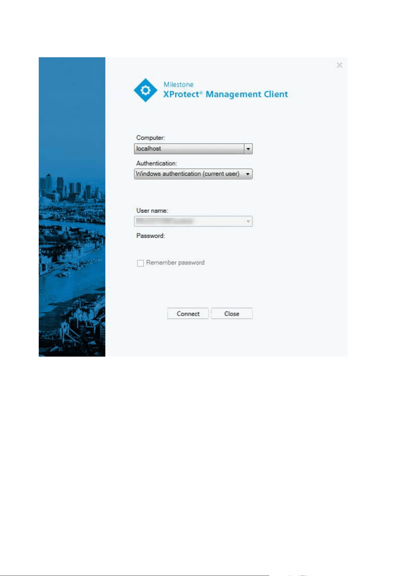
Logging in (explained)
When you launch the Management Client, you must first enter your login information to connect to a system.
With XProtect Corporate 2016 or XProtect Expert 2016 or newer installed, you can log into systems that run
older versions of the product after installing a patch. The supported versions are XProtect Corporate 2013 and
XProtect Expert 2013 or newer.
Administrator manual | XProtect® VMS 2023 R1
28 | Overview
Login authorization (explained)
The system allows administrators to set up users so they can only log into a system if a second user with
sufficient permissions authorizes their login. In this case, XProtect Smart Client or the Management Client asks
for the second authorization during login.
A user associated with the built-in Administrators role has always permission to authorize and is not asked for
a second login, unless the user is associated with another role that requires a second login.
Users logging in via an external IDP cannot be set up with a requirement to be authorized by a second user.
To associate login authorization with a role:
Administrator manual | XProtect® VMS 2023 R1
29 | Overview
l
Set Login authorization required for the selected role on the Info tab (see Roles settings) under Roles,
so that the user is asked for additional authorization during login
l
Set Authorize users for the selected role on the Overall Security tab (see Roles settings) under Roles,
so that the user can authorize other users' logins
You can choose both options for the same user. This means that the user is asked for additional authorization
during login, but can also authorize other users' logins, except for his/her own.
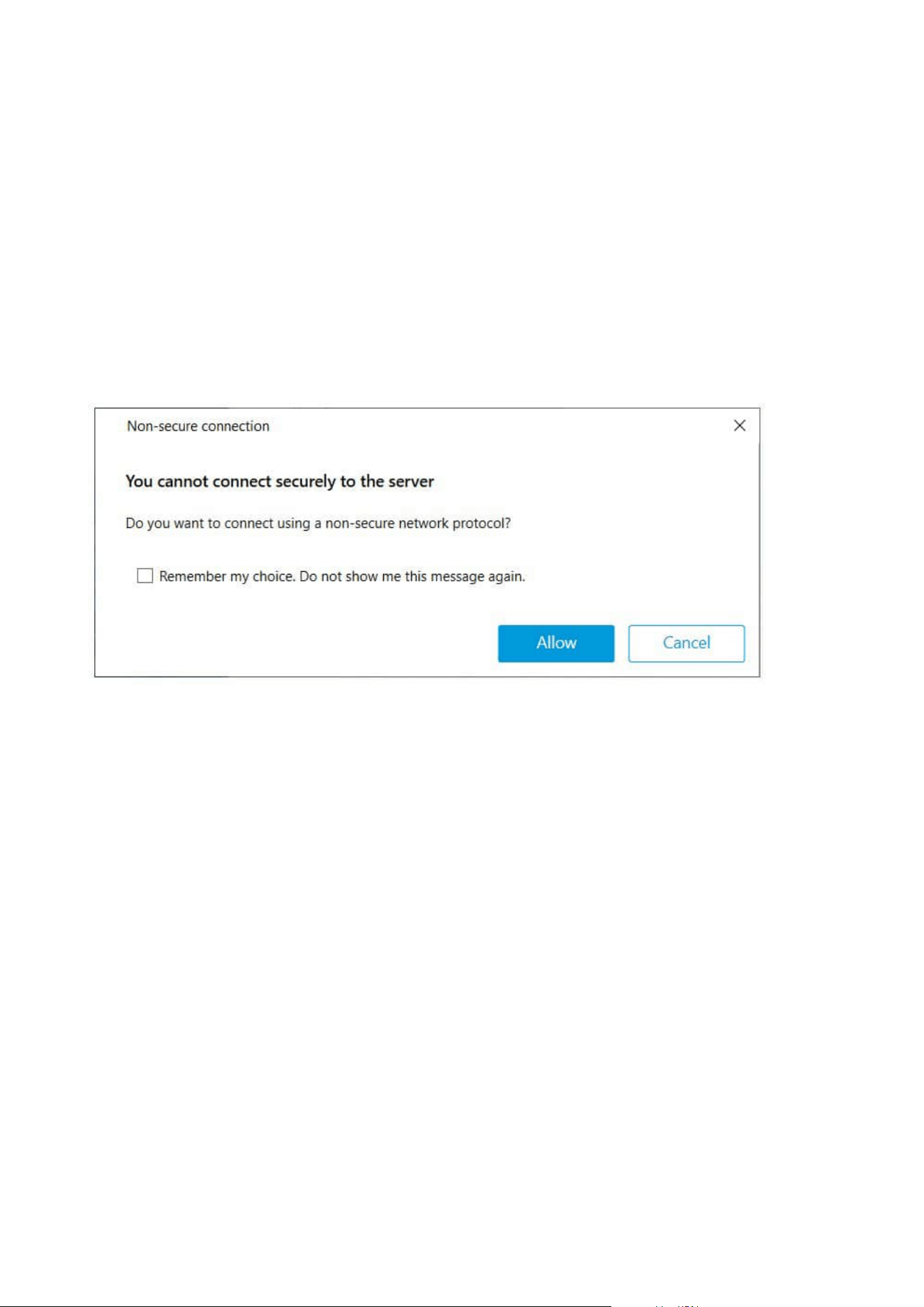
Log in using a non-secure connection
When you log in to the Management Client, you might be asked if you want to log in using a non-secure
network protocol.
l
Click Allow to log in disregarding the notification. To avoid getting this notification in the future, either
select Remember my choice. Do not show me this message again or click Tools > Options and then
select Allow non-secure connection to the server (restart of Management Client required).
For information about secure communication, see Secure communication (explained) on page 138.
Change your basic user password
If you log in as a Basic user, you can change your password. If you choose a different authentication method,
only your system administrator can change your password. Changing your password often increases the
security of your XProtect VMSsystem.
Requirements
The version of your XProtect VMS system must be 2021 R1 or later.
Steps:
Administrator manual | XProtect® VMS 2023 R1
30 | Overview
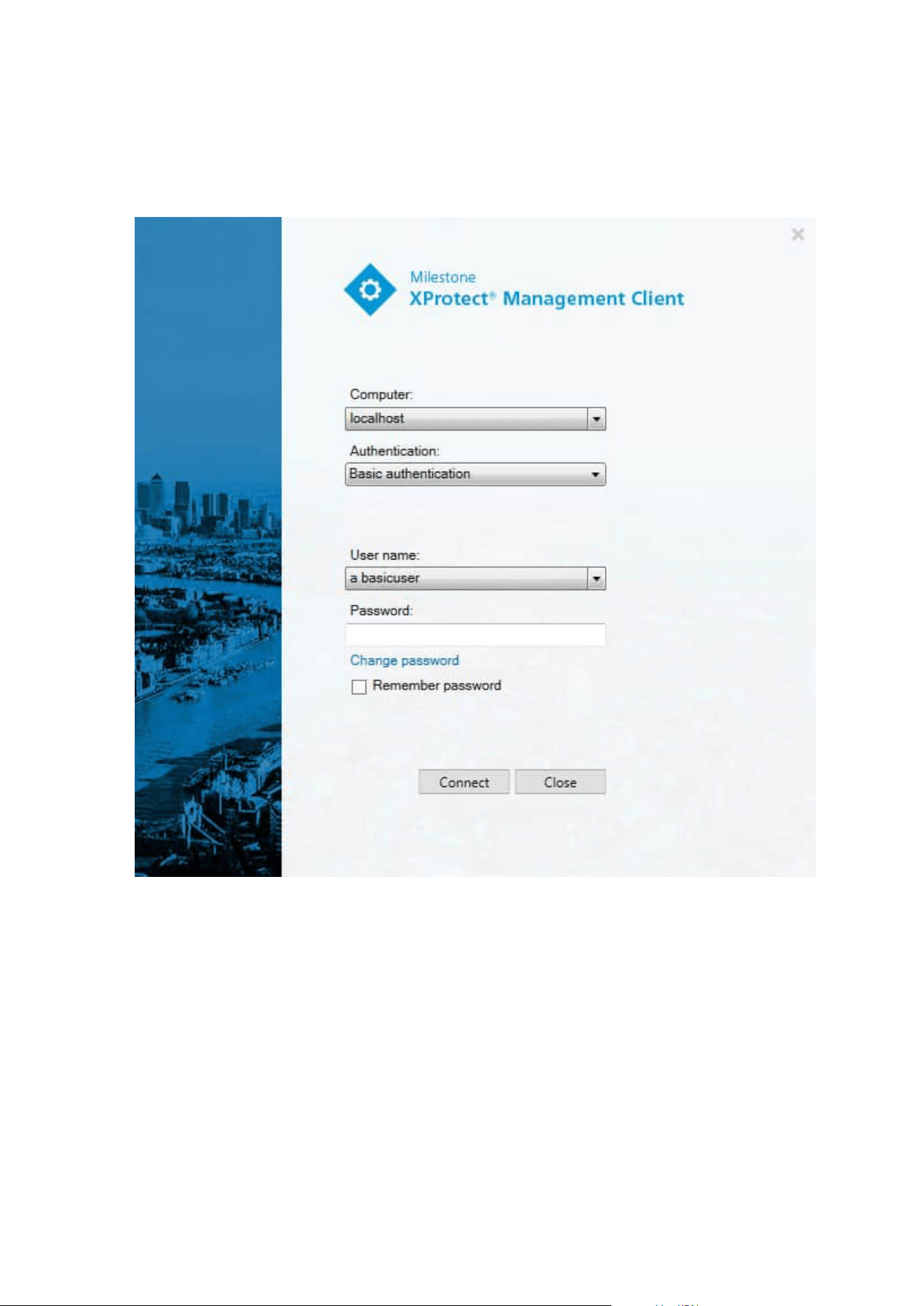
1. Start Management Client. The login window opens.
2. Specify your login information. In the Authentication list, select Basic authentication. A link with the
text Change password appears.
3. Click the link. A browser window opens.
4. Follow the instructions and save your changes.
5. Now you can log into Management Client using your new password.
Product overview
The XProtect VMS products are video management software designed for installations of all shapes and sizes.
Whether you want to protect your store from vandalism or you want to manage a multi-site, high security
installation, XProtect makes it possible. The solutions offer centralized management of all devices, servers, and
Administrator manual | XProtect® VMS 2023 R1
31 | Overview

users, and provide an extremely flexible rule system driven by schedules and events.
Your system consists of the following main components:
l
The management server - the center of your installation, consists of multiple servers
l
One or more recording servers
l
One or more installations of XProtect Management Client
l
XProtect Download Manager
l
One or more installations of XProtect® Smart Client
l
One or more uses of XProtect Web Client and/or installations of XProtect Mobile client if needed
Your system also includes fully integrated Matrix functionality for distributed viewing of video from any camera
on your surveillance system to any computer with XProtect Smart Client installed.
You can install your system on virtualized servers or on multiple physical servers in a distributed setup. See
also A distributed system setup on page 83.
The system also offers the possibility of including the standalone XProtect® Smart Client – Player when you
export video evidence from the XProtect Smart Client. XProtect Smart Client – Player allows recipients of video
evidence (such as police officers, internal or external investigators and more) to browse and play back the
exported recordings without having to install any software on their computers.
With the most feature-rich products installed (see Product comparison on page 107), your system can handle
an unrestricted number of cameras, servers, and users and across multiple sites if required. Your system can
handle IPv4 as well as IPv6.
System components
Management server (explained)
The management server is the central component of the VMS system. It stores the configuration of the
surveillance system in an SQL database, either on a SQL Server on the management server computer itself or
on a separate SQL Server on the network. It also handles user authentication, user permissions, the rule
system and more. To improve system performance, you can run several management servers as a Milestone
Federated Architecture™. The management server runs as a service and is typically installed on a dedicated
server.
Users connect to the management server for initial authentication, then transparently to the recording servers
for access to for video recordings, etc.
SQL Server installations and databases (explained)
The management server, the event server and the log server store, for example, the system configuration,
alarms, events and log messages in SQL databases on one or more SQL Server installations. The management
server and the event server share the same SQL database while the log server, XProtect Incident Manager, and
Administrator manual | XProtect® VMS 2023 R1
32 | Overview

the Identity Provider each have their own SQL database. For more information about the Identity Provider, see
Identity Provider (explained) on page 63. For more information about the XProtect Incident Manager SQL
database and logging, see the separate administrator manual for XProtect Incident Manager.
The system installer includes Microsoft SQL Server Express which is a free edition of SQL Server.
For very large systems or systems with many transactions to and from the SQL databases, Milestone
recommends that you use a Microsoft® SQL Server® Standard or Microsoft® SQL Server® Enterprise edition
of the SQL Server on a dedicated computer on the network and on a dedicated hard disk drive that is not used
for other purposes. Installing the SQL Server on its own drive improves the entire system performance.
Recording server (explained)
The recording server is responsible for communicating with the network cameras and video encoders,
recording the retrieved audio and video as well as providing client access to both live and recorded audio and
video. The recording server is also responsible for communicating with other Milestone products connected via
the Milestone Interconnect technology.
Device drivers
l
Network cameras and video encoders communicate through a device driver developed specifically for
individual devices or a series of similar devices from the same manufacturer
l
From the 2018 R1 release, the device drivers are split into two device packs: the regular device pack
with newer drivers and a legacy device pack with older drivers
l
The regular device pack is installed automatically when you install the recording server. Later, you can
update the drivers by downloading and installing a newer version of the device pack
l
The legacy device pack can only be installed if the system has a regular device pack installed. The
drivers from the legacy device pack are automatically installed if a previous version is already installed
on your system. It is available for manual download and installation on the software download page
(https://www.milestonesys.com/downloads/)
Media database
l
The recording server stores the retrieved audio and video data in the tailor-made high-performance
media database optimized for recording and storing audio and video data
l
The media database supports various unique features like; multistage archiving, video grooming,
encryption, and adding a digital signature to the recordings
The system uses recording servers for recording of video feeds, and for communicating with cameras and
other devices. A surveillance system typically consists of several recording servers.
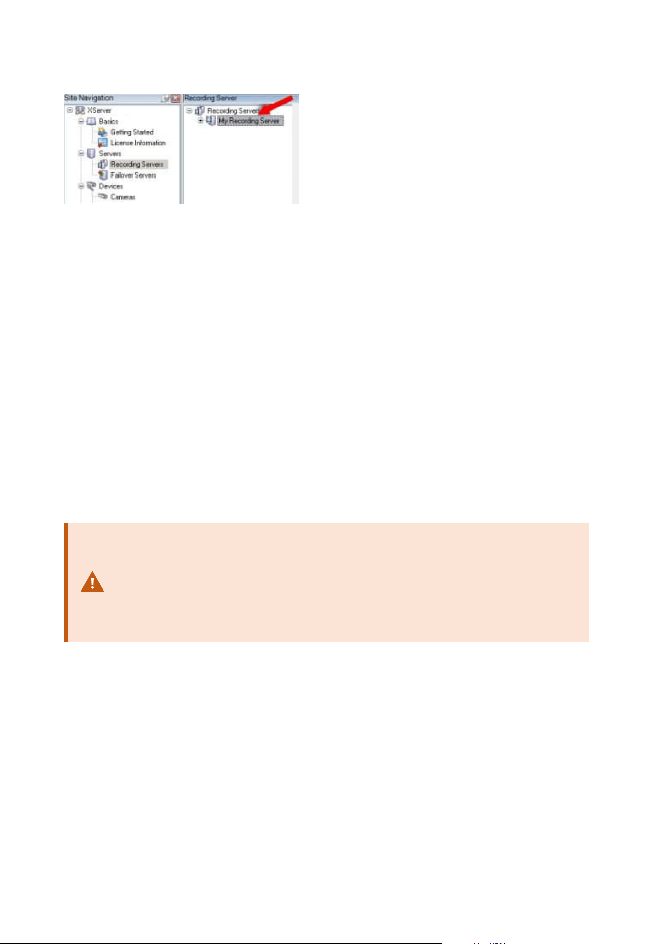
Recording servers are computers where you have installed the Recording Server software, and configured it to
communicate with the management server. You can see your recording servers in the Overview pane when
you expand the Servers folder and then select Recording Servers.
Administrator manual | XProtect® VMS 2023 R1
33 | Overview
Backward compatibility with recording server versions older than this version of the management server is
limited. You can still access recordings on recording servers with older versions, but if you want to change their
configuration, make sure they match this version of the management server. Milestone recommends that you
upgrade all recording servers in your system to the same version as your management server.
The recording server supports encryption of data streams to the clients and services:
l
Enable encryption to clients and servers on page 289
l
View encryption status to clients on page 276
The recording server also supports encryption of the connection with the management server:
l
Enable encryption to and from the management server on page 285
You have several options related to management of your recording servers:
l
Add hardware on page 203
l
Move hardware on page 324
l
Delete all hardware on a recording server on page 343
l
Remove a recording server on page 343
When the Recording Server service is running, it is very important that Windows Explorer
or other programs do not access Media Database files or folders associated with your
system setup. If they do, it is likely that the recording server cannot rename or move
relevant media files. This might bring the recording server to a halt. To restart a stopped
recording server, stop the Recording Server service, close the program accessing the
relevant media file(s) or folder(s), and restart the Recording Server service.
Mobile server (explained)
The mobile server is responsible for giving XProtect Mobile client and XProtect Web Client users access to the
system.
In addition to acting as a system gateway for the two clients, the mobile server can transcode video, since the
original camera video stream in many cases are too large to fit the bandwidth available for the client users.
If you are performing a Distributed or Custom installation, Milestone recommends that you install the mobile
server on a dedicated server.
Administrator manual | XProtect® VMS 2023 R1
34 | Overview

Event server (explained)
The event server handles various tasks related to events, alarms, and maps and perhaps also third-party
integrations via the MIP SDK.
Events
l
All system events are consolidated in the event server so there are one place and interface for partners
to make integrations that utilize system events
l
Furthermore, the event server offers third-party access to sending events to the system via the Generic
events or Analytics events interface
Alarms
l
The event server hosts the alarm feature, alarm logic, alarm state as well as handling the alarm
database. The alarm database is stored in the same SQL database that the management server uses
Maps
l
The event server also hosts the maps that are configured and used in XProtect Smart Client
MIP SDK
l
Finally, third-party-developed plug-ins can be installed on the event server and utilize access to system
events
Log server (explained)
The log server stores all log messages for the entire system in an SQL database. This log messages SQL
database can exist on the same SQL Server as the management server's system configuration SQL database or
on separate SQL Server. The log server is typically installed on the same server as the management server but
can be installed on a separate server for increased performance of the management and log servers.
API Gateway (explained)
The MIP VMS API provides a unified RESTful API, based on industry standard protocols such as OpenAPI, for
accessing XProtect VMS functionality, simplifying integration projects and serving as a basis for cloud
connected communication.
The XProtect VMS API Gateway supports these integration options through the Milestone Integration Platform
VMS API (MIP VMS API).
The API Gateway is installed on-premise and is intended to serve as a front-end and common entry point for
RESTful API services on all the current VMS server components (management server, event server, recording
servers, log server, etc). An API Gateway service can be installed on the same host as the management server
or separately, and more than one can be installed (each on their own host).
The RESTful API is implemented in part by each specific VMS server component, and the API Gateway can
simply pass-through these requests and responses, while for other requests, the API Gateway will convert
requests and responses as appropriate.
Currently, the configuration API, hosted by the management server, is available as a RESTful API.
Administrator manual | XProtect® VMS 2023 R1
35 | Overview

For more information, see the API Gateway administrator manual and the Milestone Integration Platform VMS
API reference documentation.
Failover
XProtect Management Server Failover
If a standalone computer running the Management Server service or the SQL Server has a hardware failure, it
does not affect recordings or the recording server. However, these hardware failures can result in downtime
for operators and administrators who have not logged in to the clients.
XProtect Management Server Failover provides high availability and disaster recovery for the management
server. If the management server becomes unavailable on one computer, the other computer takes over
running the system components. In cases of hardware failure, the secure real-time replication of the SQL
database contents ensures that there is no data loss.
XProtect Management Server Failover can help you mitigate system downtime. You can benefit from a failover
cluster when:
l
A server fails – you can run the Management Server service and SQL Server from another computer
while you resolve the problems.
l
You need to apply system updates and security patches – applying security patches on a standalone
management server can be time-consuming, resulting in extended periods of downtime. When you
have a failover cluster, you can apply system updates and security patches with minimal downtime.
l
You need seamless connection – users get continuous access to live and playback video, and to the
system’s configuration at all times.
You configure XProtect Management Server Failover between two computers. To make the failover work, the
following system components must run on each computer:
l
Management Server service
l
Event Server service
l
Log Server service
l
SQL Server
Failover management server (explained)
Failover support on the management server is achieved by installing the management server in a Microsoft
Windows Cluster. The cluster will then ensure that another server take over the management server function
should the first server fail.
Administrator manual | XProtect® VMS 2023 R1
36 | Overview
Failover recording server (explained)
Available functionality depends on the system you are using. See the complete feature
list, which is available on the product overview page on the Milestone website
(https://www.milestonesys.com/solutions/platform/product-index/).
A failover recording server is an extra recording server which takes over from the standard recording server if
this becomes unavailable. You can configure a failover recording server in two modes, as a cold standby
server or as a hot standby server.
You install failover recording servers like standard recording servers (see Install a failover recording server
through Download Manager on page 161). Once you have installed failover recording servers, they are visible
in the Management Client. Milestone recommends that you install all failover recording servers on separate
computers. Make sure that you configure failover recording servers with the correct IP address/host name of
the management server. The user permissions for the user account under which the Failover Server service
runs are provided during the installation process. They are:
l
Start/Stop permissions to start or stop the failover recording server
l
Read and Write access permissions to read or write the RecorderConfig.xml file
If a certificate is selected for encryption, then the administrator must grant read access permission to the
failover user on the selected certificate private key.
If the failover recording server takes over from a recording server that uses encryption,
Milestone recommends that you also prepare the failover recording server for using
encryption. For more information, see Secure communication (explained) on page 138
and Install a failover recording server through Download Manager on page 161.
You can specify what type of failover support you want on device-level. For each device on a recording server,
select full, live only or no failover support. This helps you prioritize your failover resources and, for example,
only set up failover for video and not for audio, or only have failover on essential cameras, not on less
important ones.
While your system is in failover mode, you cannot replace or move hardware, update the
recording server, or change device configurations such as storage settings or video
stream settings.
Cold standby failover recording servers
In a cold standby failover recording server setup, you group multiple failover recording servers in a failover
group. The entire failover group is dedicated to take over from any of several preselected recording servers, if
one of these becomes unavailable. You can create as many groups as you want (see Group failover recording
Administrator manual | XProtect® VMS 2023 R1
37 | Overview
servers for cold standby on page 201).
Grouping has a clear benefit: when you later specify which failover recording servers should take over from a
recording server, you select a group of failover recording servers. If the selected group contains more than
one failover recording server, this offers you the security of having more than one failover recording server
ready to take over if a recording server becomes unavailable. You can specify a secondary failover server group
that takes over from the primary group if all the recording servers in the primary group are busy. A failover
recording server can only be a member of one group at a time.
Failover recording servers in a failover group are ordered in a sequence. The sequence determines the order in
which the failover recording servers will take over from a recording server. By default, the sequence reflects
the order in which you have incorporated the failover recording servers in the failover group: first in is first in
the sequence. You can change this if you need to.
Hot standby failover recording servers
In a hot standby failover recording server setup, you dedicate a failover recording server to take over from one
recording server only. Because of this, the system can keep this failover recording server in a "standby" mode
which means that it is synchronized with the correct/current configuration of the recording server it is
dedicated to and can take over much faster than a cold standby failover recording server. As mentioned, you
assign hot standby servers to one recording server only and cannot group it. You cannot assign failover
servers that are already part of a failover group as hot standby recording servers.
Failover recording server validation
To validate a merge of video data from the failover server to the recording server, you
must make the recording server unavailable by either stopping the recording server
service or shutting down the recording server computer.
Any manual interruption of the network that you can cause by pulling out the network
cable or blocking the network using a test tool is not a valid method.
Failover recording server functionality (explained)
l
A failover recording server checks the state of relevant recording servers every 0.5 seconds. If a
recording server does not reply within 2 seconds, the recording server is considered unavailable and
the failover recording server takes over
Administrator manual | XProtect® VMS 2023 R1
38 | Overview

l
A cold standby failover recording server takes over for the recording server that has become
unavailable after five seconds plus the time it takes for the failover recording server's Recording Server
service to start and the time it takes to connect to the cameras. In contrast, a hot standby failover
recording server takes over faster because the Recording Server service is already running with the
correct configuration and only has to start its cameras to deliver feeds. During the startup period, you
can neither store recordings nor view live video from affected cameras
l
When a recording server becomes available again, it automatically takes over from the failover
recording server. Recordings stored by the failover recording server are automatically merged into the
standard recording server's databases. The time it takes to merge, depends on the amount of
recordings, network capacity and more. During the merging process, you cannot browse recordings
from the period during which the failover recording server took over
l
If a failover recording server must take over from another recording server during the merging process
in a cold standby failover recording server setup, it postpones the merging process with recording
server A, and takes over from recording server B. When recording server B becomes available again,
the failover recording server takes up the merging process and allows both recording server A and
recording server B to merge back recordings simultaneously.
l
In a hot standby setup, a hot standby server cannot take over for an additional recording server
because it can only be hot standby for a single recording server. But if that recording server fails again,
the hot standby takes over again and keeps the recordings from the previous period. The recording
server keeps recordings until they are merged back to the primary recorder or until the failover
recording server runs out of disk space
l
A failover solution does not provide complete redundancy. It can only serve as a reliable way of
minimizing the downtime. If a recording server becomes available again, the Failover Server service
makes sure that the recording server is ready to store recordings again. Only then is the responsibility
for storing recordings handed back to the standard recording server. So, a loss of recordings at this
stage of the process is very unlikely
l
Client users hardly notice that a failover recording server is taking over. A short break occurs, usually
only for a few seconds, when the failover recording server takes over. During this break, users cannot
access video from the affected recording server. Client users can resume viewing live video as soon as
the failover recording server has taken over. Because recent recordings are stored on the failover
recording server, they can play back recordings from after the failover recording server took over.
Clients cannot play back older recordings stored only on the affected recording server until that
recording server is functioning again and has taken over from the failover recording server. You cannot
access archived recordings. When the recording server is functioning again, a merging process takes
place during which failover recordings are merged back into the recording server's database. During
this process, you cannot play back recordings from the period during which the failover recording
server took over
Administrator manual | XProtect® VMS 2023 R1
39 | Overview
l
In a cold standby setup, setting up a failover recording server as backup for another failover recording
server is not necessary. This is because you allocate failover groups and do not allocate particular
failover recording servers to take over from specific recording servers. A failover group must contain at
least one failover recording server, but you can add as many failover recording servers as needed. If a
failover group contains more than one failover recording server, more than one failover recording
server can take over.
l
In a hot standby setup, you cannot set up failover recording servers or hot standby servers as failover
for a hot standby server
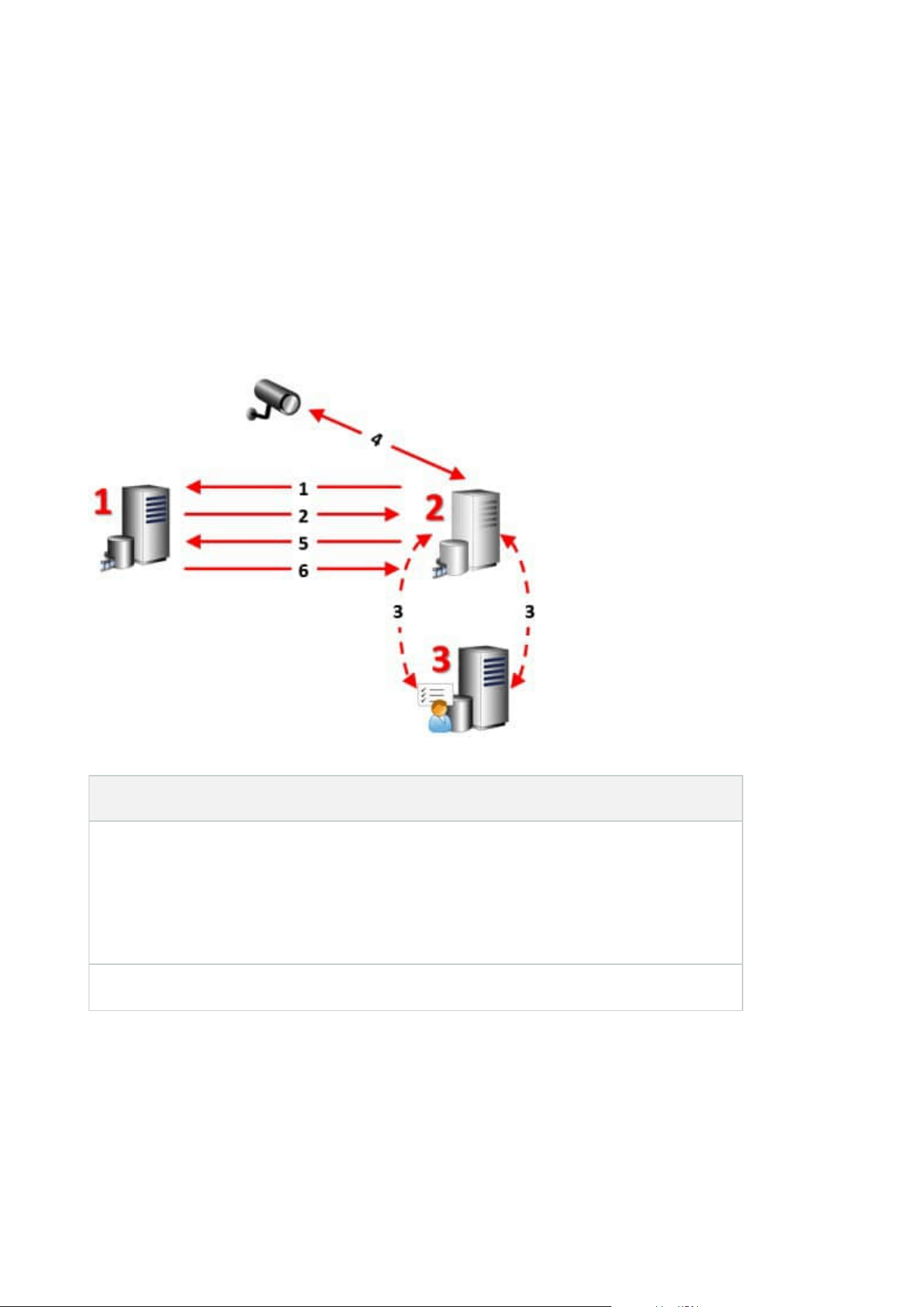
Failover steps (explained)
Description
Involved servers (numbers in red):
1. Recording Server
2. Failover Recording Server
3. Management Server
Failover steps for Cold standby setups:
Administrator manual | XProtect® VMS 2023 R1
40 | Overview

Description
1. To check whether it is running or not, a failover recording server has a non-stop TCP
connection to a recording server.
2. This connection is interrupted.
3. The failover recording server requests the current configuration of the recording server
from the management server. The management server sends the requested
configuration, the failover recording server receives the configuration, starts up, and
starts recording on behalf of the recording server.
4. The failover recording server and the relevant camera(s) exchange video data.
5. The failover recording server continually tries to re-establish connection to the recording
server.
6. When the connection to the recording server is re-established, the failover recording
server shuts down and the recording server fetches video data (if any) recorded during
its downtime and the video data is merged back in to the recording server database.
Failover steps for Hot standby setups:
1. To check whether it is running or not, a hot standby server has a non-stop TCP
connection to its assigned recording server.
2. This connection is interrupted.
3. From the management server, the hot standby server already knows the current
configuration of its assigned recording server and starts recording on its behalf.
4. The hot standby server and the relevant camera(s) exchange video data.
5. The hot standby server continually tries to re-establish connection to the recording
server.
6. When the connection to the recording server is re-established and the hot standby
server goes back to hot standby mode, the recording server fetches video data (if any)
recorded during its down-time and the video data is merged back in to the recording
server database.
Failover recording server services (explained)
A failover recording server has two services installed:
Administrator manual | XProtect® VMS 2023 R1
41 | Overview

l
A Failover Server service, which handles the processes of taking over from the recording server. This
service is always running, and constantly checks the state of relevant recording servers
l
A Failover Recording Server service, which enables the failover recording server to act as a recording
server.
In a cold standby setup, this service is only started when required, that is when the cold standby failover
recording server takes over from the recording server. Starting this service typically takes a couple of
seconds, but may take longer depending on local security settings and more.
In a hot standby setup, this service is always running, allowing the hot standby server to take over
faster than the cold standby failover recording server.
Clients
Management Client (explained)
The Management Client is a feature-rich administration client for configuration and day-to-day management of
the system. Available in several languages.
Typically installed on the surveillance system administrator's workstation or similar.
XProtect Smart Client (explained)
XProtect Smart Client is a desktop application designed to help you manage your IPsurveillance cameras. It
provides intuitive control over security installations by giving users access to live and recorded video, instant
control of cameras and connected security devices, and the ability to make advanced searches for recordings
and metadata.
Available in multiple local languages, XProtect Smart Client has an adaptable user interface that can be
optimized for individual operators’ tasks and adjusted according to specific skills and authority levels.
Administrator manual | XProtect® VMS 2023 R1
42 | Overview
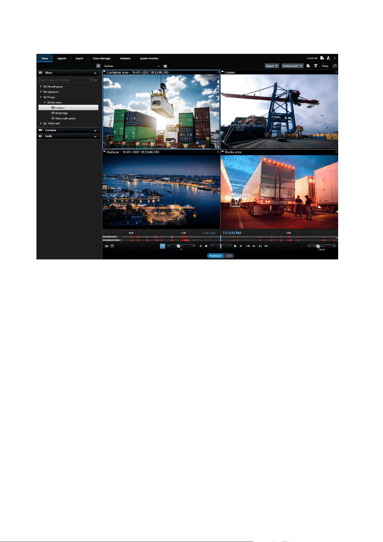
The interface allows you to tailor your viewing experience to specific working environments by selecting a light
or dark theme. It also features work-optimized tabs and an integrated video timeline for easy surveillance
operation.
Using the MIP SDK, users can integrate various types of security and business systems, and video analytics
applications, which you manage through XProtect Smart Client.
XProtect Smart Client must be installed on operators' computers. Surveillance system administrators manage
access to the surveillance system through the Management Client. Recordings viewed by clients are provided
by your XProtect system's Image Server service. The service runs in the background on the surveillance system
server. Separate hardware is not required.
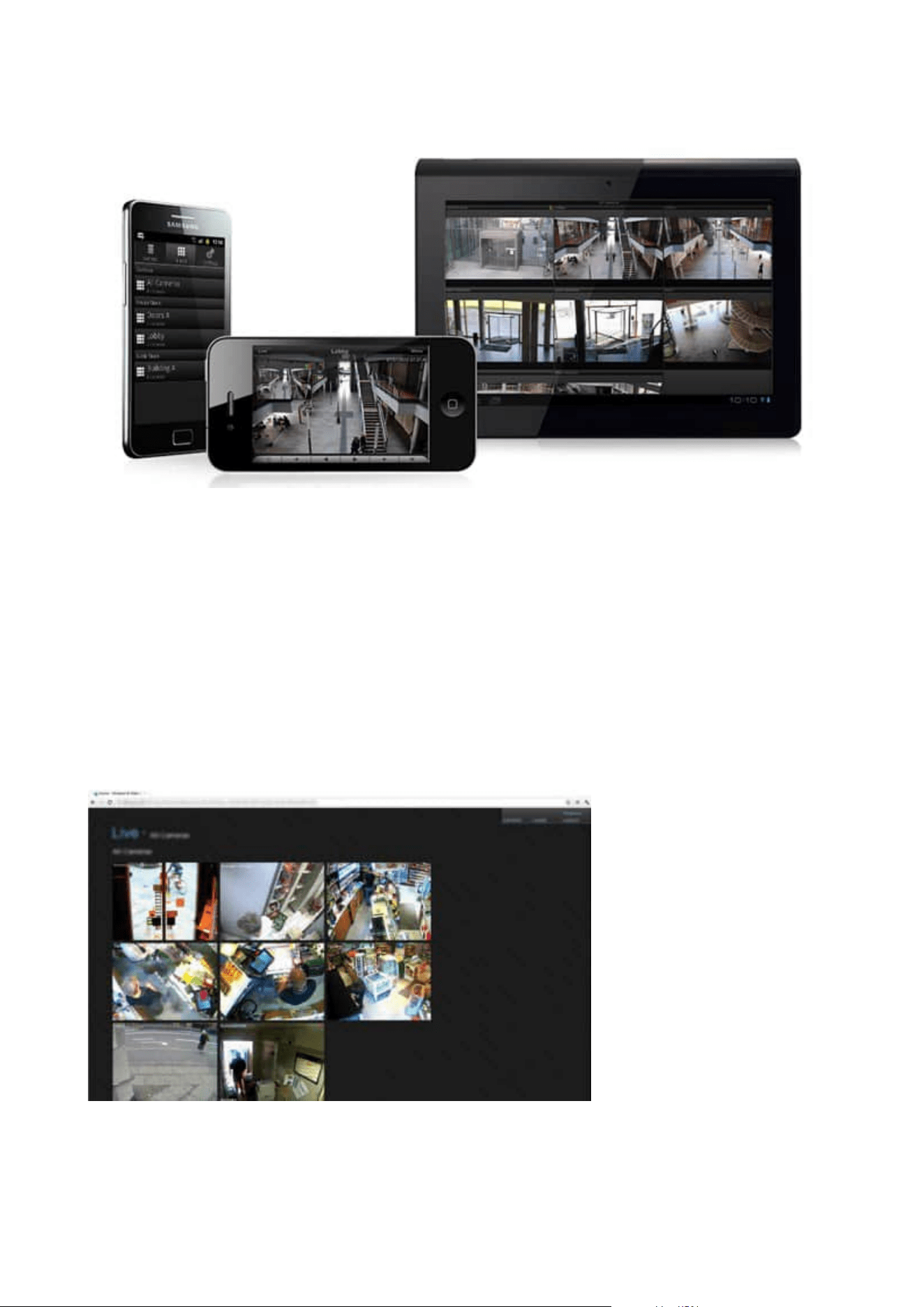
XProtect Mobile client (explained)
XProtect Mobile client is a mobile surveillance solution closely integrated with the rest of your XProtect system.
It runs on your Android tablet or smartphone or your Apple
®
tablet, smartphone or portable music player and
gives you access to cameras, views and other functionality set up in the management clients.
Use the XProtect Mobile client to view and play back live and recorded video from one or multiple cameras,
control pan-tilt-zoom (PTZ) cameras, trigger output and events and use the Video push functionality to send
video from your device to your XProtect system.
Administrator manual | XProtect® VMS 2023 R1
43 | Overview
If you want to use the XProtect Mobile client with your system, you must have a XProtect Mobile server to
establish the connection between the XProtect Mobile client and your system. Once the XProtect Mobile server
is set up, download the XProtect Mobile client for free from Google Play or App Store to start using XProtect
Mobile.
You need one device license per device that should be able to push video to your XProtect system.
XProtect Web Client (explained)
XProtect Web Client is a web-based client application for viewing, playing back and sharing video. It provides
instant access to the most commonly used surveillance functions, such as viewing live video, play back
recorded video, print and export evidence. Access to features depends on individual user permissions which
are set up in Management Client.
Administrator manual | XProtect® VMS 2023 R1
44 | Overview
To enable access to the XProtect Web Client, you must have a XProtect Mobile server to establish the
connection between the XProtect Web Client and your system. The XProtect Web Client itself does not require
any installation itself and works with most Internet browsers. Once you have set up the XProtect Mobile server,
you can monitor your XProtect system anywhere from any computer or tablet with Internet access (provided
you know the correct external/Internet address, user name and password).
Add-on products
XProtect Access (explained)
Milestone has developed add-on products that fully integrate with XProtect to give you extra functionality.
Your XProtect license file controls the access to add-on products.
The use of XProtect Access requires that you have purchased a base license that allows
you to access this feature within your XProtect system. You also need an access control
door license for each door you want to control.
You can use XProtect Access with access control systems from vendors where a vendor-
specific plug-in for XProtect Access exists.
The access control integration feature introduces new functionality that makes it simple to integrate
customers’ access control systems with XProtect. You get:
l
A common operator user interface for multiple access control systems in XProtect Smart Client
l
Faster and more powerful integration of access control systems
l
More functionality for the operator (see below)
In XProtect Smart Client, the operator gets:
l
Live monitoring of events at access points
l
Operator aided passage for access requests
l
Map integration
l
Alarm definitions for access control events
l
Investigation of events at access points
l
Centralized overview and control of door states
l
Cardholder information and management
The Audit log logs the commands that each user performs in the access control system from XProtect Smart
Client.
Administrator manual | XProtect® VMS 2023 R1
45 | Overview

Apart from a XProtect Access base license, you need a vendor-specific integration plug-in installed on the event
server before you can start an integration.
XProtect Incident Manager
Milestone has developed add-on products that fully integrate with XProtect to give you extra functionality.
Your XProtect license file controls the access to add-on products.
Available functionality depends on the system you are using. See the complete feature
list, which is available on the product overview page on the Milestone website
(https://www.milestonesys.com/solutions/platform/product-index/).
XProtect Incident Manager is a Milestone add-on that enables organizations to document incidents and
combine them with sequence evidence (video and, potentially, audio) from the XProtect VMS.
Users of XProtect Incident Manager can save all the incident information in incident projects. From the incident
projects, they can track the status and activities of each incident. In this way, the users can manage incidents
effectively and easily share strong incident evidence, both internally with colleagues and externally with
authorities.
XProtect Incident Manager helps organizations gain an overview and understanding of the incidents
happening in the areas they survey. This knowledge enables the organizations to implement steps to minimize
the chance that similar incidents happen in the future.
In XProtect Management Client, the administrators of an organization’s XProtect VMS can define the available
incident properties in XProtect Incident Manager to the organizations’ needs. The operators of XProtect Smart
Client start, save, and manage incident projects and add various information to the incident projects. This
includes free text, incident properties that the administrators have defined, and sequences from the XProtect
VMS. For full traceability, the XProtect VMS logs when administrators define and edit incident properties and
when operators create and update the incident projects.
XProtect LPR (explained)
Milestone has developed add-on products that fully integrate with XProtect to give you extra functionality.
Your XProtect license file controls the access to add-on products.
Available functionality depends on the system you are using. See the complete feature list, which is available
on the product overview page on the Milestone website
(https://www.milestonesys.com/solutions/platform/product-index/).
XProtect LPR offers video-based content analysis (VCA) and recognition of vehicle license plates that interacts
with your surveillance system and your XProtect Smart Client.
To read the characters on a plate, XProtect LPR uses optical character recognition on images aided by
specialized camera settings.
Administrator manual | XProtect® VMS 2023 R1
46 | Overview

You can combine LPR (license plate recognition) with other surveillance features such as recording and event-
based activation of outputs.
Examples of events in XProtect LPR:
l
Trigger surveillance system recordings in a particular quality
l
Activate alarms
l
Match against positive and negative match lists
l
Open gates
l
Switch on lights
l
Push video of incidents to computer screens of particular security staff members
l
Send mobile phone text messages
With an event, you can activate alarms in XProtect Smart Client.
XProtect Smart Wall (explained)
See also the Smart Wall manual (https://doc.milestonesys.com/2023r1/en-US/portal/htm/chapter-page-smart-
wall.htm).
Milestone has developed add-on products that fully integrate with XProtect to give you extra functionality.
Your XProtect license file controls the access to add-on products.
XProtect Smart Wall is an advanced add-on tool that enables organizations to create video walls that meet their
specific security demands. XProtect Smart Wall provides an overview of all the video data in the XProtect VMS
1
system and supports any amount or combination of monitors.
1
Short for "Video Management Software".
Administrator manual | XProtect® VMS 2023 R1
47 | Overview

XProtect Smart Wall allows operators to view static video walls as defined by their system administrator with a
fixed set of cameras and monitor layout. However, the video wall is also operator-driven in the sense that
operators can control what is being displayed. This includes:
l
Pushing cameras and other types of content to the video wall, for example images, text, alarms, and
smart map
l
Sending entire views to the monitors
l
In the course of certain events, applying alternate presets
1
Finally, display changes can be controlled by rules that automatically change the presets based on specific
events or time schedules.
XProtect Transact (explained)
Milestone has developed add-on products that fully integrate with XProtect to give you extra functionality.
Your XProtect license file controls the access to add-on products.
1
A predefined layout for one or more Smart Wall monitors in XProtect Smart Client. Presets determine which
cameras are displayed, and how content is structured on each monitor on the video wall.
Administrator manual | XProtect® VMS 2023 R1
48 | Overview

Available functionality depends on the system you are using. See the complete feature
list, which is available on the product overview page on the Milestone website
(https://www.milestonesys.com/solutions/platform/product-index/).
XProtect Transact is an add-on to Milestone's IP video surveillance solutions.
XProtect Transact is a tool for observing ongoing transactions and investigating transactions in the past. The
transactions are linked with the digital surveillance video monitoring the transactions, for example to help you
prove fraud or provide evidence against a perpetrator. There is a 1-to-1 relationship between the transaction
lines and video images.
The transaction data may originate from different types of transaction sources, typically point of sales (PoS)
systems or automated teller machines (ATM).
Milestone Open Network Bridge (explained)
Milestone has developed add-on products that fully integrate with XProtect to give you extra functionality.
Your XProtect license file controls the access to add-on products.
Milestone Open Network Bridge is an open ONVIF compliant interface for standardized video sharing from
XProtect VMS systems to other IP-based security systems. This enables law enforcement, surveillance centers,
or similar organizations (referred to as ONVIF clients) to access live and recorded video streams from the
XProtect VMS system to the central monitoring solutions. The video streams are sent as RTSP streams over the
Internet.
The key benefits are:
l
Enables true interoperability and freedom of choice for large-scale, multi-vendor security deployments
and seamless private-to-public video integration
l
Provides external access to H.264 and H.265 video streams in the XProtect VMS system, both live video
and playback
l
Offers standardized interfaces that provide an easy and problem-free way of integrating XProtect VMS
solutions with alarm centers and monitoring stations
This document provides the following:
l
Information about the ONVIF standard and links to reference materials
l
Instructions for installing and configuring the Milestone Open Network Bridge in your XProtect VMS
product
l
Examples of how to enable various types of ONVIF clients to stream live and recorded video from
XProtect VMS products
Administrator manual | XProtect® VMS 2023 R1
49 | Overview
XProtect DLNA Server (explained)
Milestone has developed add-on products that fully integrate with XProtect to give you extra functionality.
Your XProtect license file controls the access to add-on products.
DLNA (Digital Living Network Alliance) is a standard for connecting multimedia devices. Electronic
manufactures get their products DLNA certified to ensure interoperability between different vendors and
devices and thereby enable them to distribute video content.
Public displays and TVs are often DLNA certified and connected to a network. They are able to scan the
network for media content, connect to the device, and request a media stream to their built-in media player.
XProtect DLNA Server can be discovered by certain DLNA certified devices and deliver live video streams from
selected cameras to DLNA certified devices with a media player.
The DLNA devices have a live video delay of 1-10 seconds. This is caused by different
buffer sizes in the devices.
XProtect DLNA Server must be connected to the same network as the XProtect system and the DLNA device
must be connected to the same network as XProtect DLNA Server.
Devices
Hardware (explained)
Hardware represents either:
l
The physical unit that connects directly to the recording server of the surveillance system via IP, for
example a camera, a video encoder, an I/O module
l
A recording server on a remote site in a Milestone Interconnect setup
You have several options for adding hardware to each recording server in your system.
If your hardware is located behind a NAT-enabled router or a firewall, you may need to
specify a different port number and configure the router/firewall so it maps the port and
IP addresses that the hardware uses.
The Add Hardware wizard helps you detect hardware like cameras and video encoders on your network and
add them to the recording servers on your system. The wizard also helps you add remote recording servers for
Milestone Interconnect setups. Only add hardware to one recording server at a time.
Administrator manual | XProtect® VMS 2023 R1
50 | Overview
Hardware pre-configuration (explained)
Certain manufacturers require that credentials be set on out-of-the-box hardware before adding the hardware
to a VMS system for the first time. This is referred to as hardware pre-configuration, and is done through the
Pre-configure hardware devices wizard that appears when such hardware is detected by the Add hardware
on page 203 wizard.
Some important information regarding the Pre-configure hardware devices wizard:
l
Hardware that requires initial credentials before being added to a VMSsystem cannot be added using
the typical default credentials, and must be configured through the wizard or by connecting to the
hardware directly
l
You can only apply credentials (user name or password) to fields that are marked as not set
l
Once the hardware status is set to configured, you cannot change the credentials (user name or
password)
l
Pre-configuration applies to out-of-the-box hardware and needs to be done only once. Once pre-
configured, hardware can be managed like any other hardware in Management Client
l
After you close the Pre-configure hardware devices wizard, pre-configured hardware will appear in the
in the Add hardware on page 203 wizard, and can now be added to your system
It is highly recommended that you add the pre-configured hardware to your system by
completing the Add hardware on page 203 wizard after you close the Pre-configure
hardware devices wizard. Management Client will not retain the pre-configured
credentials if you do not add the hardware to your system.
Devices (explained)
Hardware has a number of devices that you can manage individually, for example:
l
A physical camera has devices that represent the camera part (lenses) as well as microphones,
speakers, metadata, input and output either attached or built-in
l
A video encoder has multiple analog cameras connected that appear in one list of devices that
represent the camera part (lenses) as well as microphones, speakers, metadata, input and output either
attached or built-in
l
An I/O module has devices that represent the input and output channels for, for example, lights
l
A dedicated audio module has devices that represent microphones and speaker inputs and outputs
l
In a Milestone Interconnect setup, the remote system appears as hardware with all devices from the
remote system listed in one list
The system automatically adds the hardware’s devices when you add hardware.
Administrator manual | XProtect® VMS 2023 R1
51 | Overview

For information about supported hardware, see the supported hardware page on the
Milestone website (https://www.milestonesys.com/support/tools-and-
references/supported-devices/).
The following sections describe each of the device types that you can add.
Cameras
Camera devices deliver video streams to the system that the client users can use to view live video or that the
system can record for later playback by the client users. Roles determine the users' permission to view video.
Microphones
On many devices, you can attach external microphones. Some devices have built-in microphones.
Microphone devices deliver audio streams to the system that the client users can listen to live or the system
can record for later playback by the client users. You can set up the system to receive microphone-specific
events that trigger relevant actions.
Roles determine the users' permission to listen to microphones. You cannot listen to microphones from the
Management Client.
Speakers
On many devices you can attach external speakers. Some devices have built-in speakers.
The system sends an audio stream to the speakers when a user presses the talk button in XProtect Smart
Client You can also use this feature from XProtect Web Client and XProtect® Mobile. Speaker audio is only
recorded when talked to by a user. Roles determine users' permission to talk through speakers. You cannot
talk through speakers from the Management Client.
If two users want to speak at the same time, the roles determine users' permission to talk through speakers.
As part of the roles definition, you can specify a speaker priority from very high to very low. If two users want
to speak at the same time, the user whose role has the highest priority wins the ability to speak. If two users
with the same role want to speak at the same time, the first-come first-served principle applies.
Metadata
Metadata devices deliver data streams to the system that the client users can use to view data about data, for
example, data that describes the video image, the content or objects in the image, or the location of where the
image was recorded. Metadata can be attached to cameras, microphones, or speakers.
Metadata can be generated by:
l
The device itself delivering the data, for example a camera that is delivering video
l
A third-party system or integration via a generic metadata driver
The device-generated metadata is automatically linked to one or more devices on the same hardware.
Administrator manual | XProtect® VMS 2023 R1
52 | Overview

Roles determine the users' permission to view metadata.
Inputs
On many devices, you can attach external units to input ports on the device. Input units are typically external
sensors. You can use such external sensors, for example, for detecting if doors, windows, or gates are opened.
Input from such external input units is treated as events by the system.
You can use such events in rules. For example, you could create a rule specifying that a camera should begin
recording when an input is activated, and stop recording 30 seconds after the input is deactivated.
Outputs
On many devices, you can attach external units to output ports on the device. This allows you to
activate/deactivate lights, sirens, etc. through the system.
You can use output when creating rules. You can create rules that automatically activate or deactivate outputs,
and rules that trigger actions when the state of an output is changed.
Device groups (explained)
Grouping of devices into device groups is part of the Add Hardware wizard, but you can always modify the
groups and add more groups if needed.
You can benefit from grouping different types of devices (cameras, microphones, speakers, metadata, inputs,
and outputs) on your system:
l
Device groups help you maintain an intuitive overview of devices on your system
l
Devices can exist in several groups
l
You can create subgroups and subgroups in subgroups
l
You can specify common properties for all devices within a device group in one go
l
Device properties set via the group are not stored for the group but on the individual devices
l
When dealing with roles, you can specify common security settings for all devices within a device group
in one go
l
When dealing with rules, you can apply a rule for all devices within a device group in one go
You can add as many device groups as required, but you cannot mix different types of devices (for example
cameras and speakers) in a device group.
Administrator manual | XProtect® VMS 2023 R1
53 | Overview
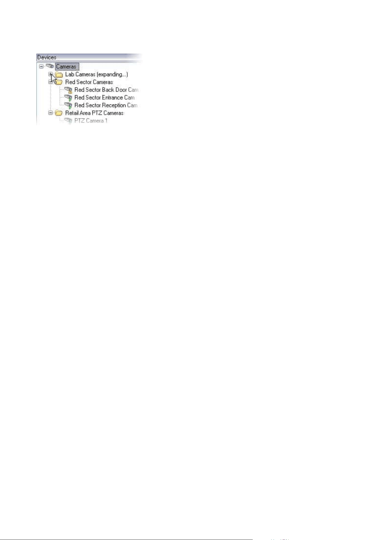
Create device groups with less than 400 devices so you can view and edit all properties.
If you delete a device group, you only delete the device group itself. If you want to delete a device, for example
a camera, from your system, do it on the recording server level.
The following examples are based on grouping cameras into device groups, but the principles apply for all
devices
Add a device group
Specify which devices to include in a device group
Specify common properties for all devices in a device group
Media storage
Storage and archiving (explained)
Available functionality depends on the system you are using. See the complete feature list, which is available
on the product overview page on the Milestone website
(https://www.milestonesys.com/solutions/platform/product-index/).
On the Storage tab, you can set up, manage and view storages for a selected recording server.
For recording storages and archives, the horizontal bar shows the current amount of free space. You can
specify the behavior of the recording server in case recording storages become unavailable. This is mostly
relevant if your system includes failover servers.
If you are using Evidence lock, there will be a vertical red line showing the space used for evidence locked
footage.
Administrator manual | XProtect® VMS 2023 R1
54 | Overview
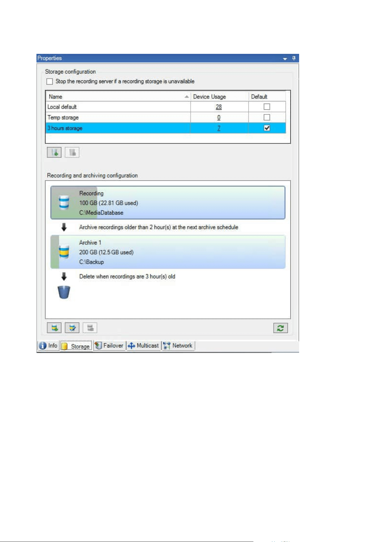
When a camera records video or audio, all specified recordings are by default stored in the storage defined for
the device. Each storage consists of a recording storage that saves recordings in the recording database
Recording. A storage has no default archive(s), but you can create these.
To avoid that the recording database runs full, you can create additional storages (see Add a new storage on
page 188). You can also create archives (see Create an archive within a storage on page 189) within each
storage and start an archiving process to store data.
Administrator manual | XProtect® VMS 2023 R1
55 | Overview
Archiving is the automatic transfer of recordings from, for example, a camera's
recording database to another location. In this way, the amount of recordings that you
can store is not limited to the size of the recording database. With archiving you can also
back up your recordings to another media.
You configure storage and archiving on each recording server.
As long as you store archived recordings locally or on accessible network drives, you can use XProtect Smart
Client to view them.
If a disk drive breaks and the recording storage becomes unavailable, the horizontal bar turns red. It is still
possible to view live video in XProtect Smart Client, but recording and archiving stops until the disk drive is
restored. If your system is configured with failover recording servers, you can specify the recording server to
stop running, to let the failover servers take over (see Specify behavior when recording storage is unavailable
on page 187).
The following mostly mentions cameras and video, but speakers, microphones, audio and sound also apply.
Milestone recommends that you use a dedicated hard disk drive for recording storages
and archives to prevent low disk performance. When you format the hard disk, it is
important to change its Allocation unit size setting from 4 to 64 kilobytes. This is to
significantly improve recording performance of the hard disk. You can read more about
allocating unit sizes and find help on the Microsoft website
(https://support.microsoft.com/en-us/topic/default-cluster-size-for-ntfs-fat-and-exfat-
9772e6f1-e31a-00d7-e18f-73169155af95).
The oldest data in a database is always auto-archived (or deleted if no next archive is
defined) when less than 5GB of space is free. If less than 1GB space is free, data is
deleted. A database always requires 250MB of free space. If you reach this limit because
data is not deleted fast enough, attempts to write to the database might fail and in that
case no more data is written to the database until you free up enough space. The actual
maximum size of your database becomes the amount of gigabytes that you specify,
minus 5GB.
Administrator manual | XProtect® VMS 2023 R1
56 | Overview

For FIPS 140-2 compliant systems, with exports and archived media databases from
XProtect VMS versions prior to 2017 R1 that are encrypted with non FIPS-compliant
cyphers, it is required to archive the data in a location where it can still be accessed after
enabling FIPS. For detailed information on how to configure your XProtect VMS to run in
FIPS 140-2 compliant mode, see the FIPS 140-2 compliance section in the hardening
guide.
Attaching devices to a storage
Once you have configured the storage and archiving settings for a recording server, you can enable storage
and archiving for individual cameras or a group of cameras. You do this from the individual devices or from the
device group. See Attach a device or group of devices to a storage on page 189.
Effective archiving
When you enable archiving for a camera or a group of cameras, the content of the recording storage is
automatically moved to the first archive at intervals that you define.
Depending on your requirements, you can configure one or more archives for each of your storages. Archives
can be located either on the recording server computer itself, or at another location which can be reached by
the system, for example on a network drive.
By setting up your archiving in an effective way, you can optimize storage needs. Often, you want to make
archived recordings take up as little space as possible, especially on a long-term basis, where it is perhaps even
possible to slacken image quality a bit. You handle effective archiving from the Storage tab of a recording
server by adjusting several interdependent settings:
l
Recording storage retention
l
Recording storage size
l
Archive retention
l
Archive size
l
Archive schedule
l
Encryption
l
Frames Per Second (FPS).
The size fields define the size of the recording storage, exemplified by the cylinder, and its archive(s)
respectively:
Administrator manual | XProtect® VMS 2023 R1
57 | Overview
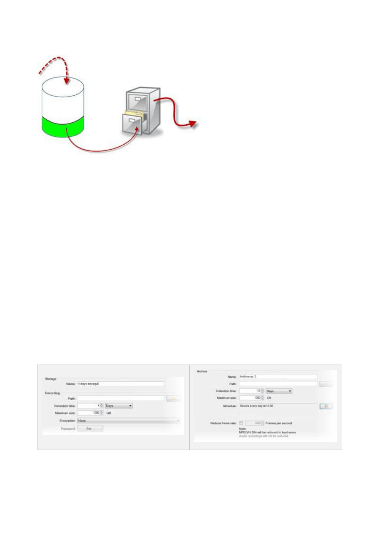
By means of retention time and size setting for the recording storage, exemplified by the white area in the
cylinder, you define how old recordings must be before they are archived. In our illustrated example, you
archive the recordings when they are old enough to be archived.
The retention time and size setting for archives define how long the recordings remain in the archive.
Recordings remain in the archive for the time specified, or until the archive has reached the specified size limit.
When these settings are met, the system begins to overwrite old recordings in the archive.
The archiving schedule defines how often and at what times archiving takes place.
FPS determines the size of the data in the databases.
To archive your recordings, you must set all these parameters up in accordance with each other. This means
that the retention period of the next archive must always be longer than the retention period of a current
archive or recording database. This is because the number of retention days stated for an archive includes all
retention stated earlier in the process. Archiving must also always take place more frequently than the
retention period, otherwise you risk losing data. If you have a retention time of 24 hours, any data older than
24 hours is deleted. Therefore, to get your data safely moved to the next archive, it is important to run
archiving more often than every 24 hours.
Example: These storages (image to the left) have a retention time of 4 days and the following archive (image to
the right) a retention time of 10 days. Archiving is set to occur every day at 10:30, ensuring a much more
frequent archiving than retention time.
Administrator manual | XProtect® VMS 2023 R1
58 | Overview
You can also control archiving by use of rules and events.
Archive structure (explained)
When you archive recordings, they are stored in a certain sub-directory structure within the archive.
During all regular use of your system, the sub-directory structure is completely
transparent to the system's users, as they browse all recordings with the XProtect Smart
Client regardless of whether the recordings are archived or not. Knowing the sub-
directory structure is primarily interesting if you want to back up your archived
recordings.
In each of the recording server's archive directories, the system automatically creates separate sub-directories.
These sub-directories are named after the name of the device and the archive database.
Because you can store recordings from different cameras in the same archive, and since archiving for each
camera is likely to be performed at regular intervals, further sub-directories are also automatically added.
These sub-directories each represent approximately an hour's worth of recordings. The one-hour split makes it
possible to remove only relatively small parts of an archive's data if you reach the maximum allowed size of the
archive.
The sub-directories are named after the device, followed by an indication of where the recordings came from
(edge storage or via SMTP), plus the date and time of the most recent database record contained in the sub-
directory.
Naming structure
...[Storage Path]\[Storage name]\[device-name] - plus date and time of most
recent recording]\
If from edge storage:
...[Storage Path]\[Storage name]\[device-name] (Edge) - plus date and time of
most recent recording]\
If from SMTP:
...[Storage Path]\[Storage name]\[device-name] (SMTP) - plus date and time of
most recent recording]\
Real life example
Administrator manual | XProtect® VMS 2023 R1
59 | Overview

...F:\OurArchive\Archive1\Camera 1 on Axis Q7404 Video Encoder(10.100.50.137) -
2011-10-05T11:23:47+02:00\
Sub-directories
Even further sub-directories are automatically added. The amount and nature of these sub-directories depend
on the nature of the actual recordings. For example, several different sub-directories are added if the
recordings are technically divided into sequences. This is often the case if you have used motion detection to
trigger recordings.
l
Media: This folder contains the actual media that is either video or audio (not both)
l
MotionLevel: This folder contains motion level grids generated from the video data using our motion
detection algorithm. This data allows the Smart Search feature in XProtect Smart Client to do very fast
searches
l
Motion: In this folder, the system stores motion sequences. A motion sequence is a time slice for which
motion has been detected in the video data. This information is, for example, used in the time line in
XProtect Smart Client
l
Recording: In this folder, the system stores recording sequences. A recording sequence is a time slice
for which there are coherent recordings of media data. This information is, for example, used to draw
the time line in XProtect Smart Client
l
Signature: This folder holds the signatures generated for the media data (in the Media folder). With this
information, you can verify that the media data has not been tampered with since it was recorded
If you want to back up your archives, you can target your backups if you know the basics of the sub-directory
structure.
Examples of backup
To back up the content of an entire archive, back up the required archive directory and all of its content. For
example, everything under:
...F:\OurArchive\
To back up the recordings from a particular camera from a particular period of time, back up the contents of
the relevant sub-directories only. For example, everything under:
...F:\OurArchive\Archive1\Camera 1 on Axis Q7404 Video Encoder(10.100.50.137) -
2011-10-05T11:23:47+02:00\
Pre-buffering and storage of recordings (explained)
Pre-buffering is the ability to record audio and video before the actual triggering event occurs. This is useful
when you want to record the audio or video that leads up to an event that triggers recording, for example,
opening a door.
Administrator manual | XProtect® VMS 2023 R1
60 | Overview

Pre-buffering is possible because the system continuously receives audio and video streams from the
connected devices and temporarily stores them for the defined pre-buffer period.
l
If a recording rule is triggered, the temporary recordings are made permanent for the rule’s configured
pre-recording time
l
If no recording rule is triggered, the temporary recordings in the pre-buffer are automatically deleted
after the defined pre-buffer time
Storage of the temporary pre-buffer recordings
You can choose the storage location of the temporary pre-buffer recordings:
l
In the memory; the pre-buffer period is limited to 15 seconds.
l
On the disk (in the media database); you can choose all values.
Storage to the memory instead of to disk improves system performance but is only possible for shorter pre-
buffer periods.
When recordings are stored in the memory, and you make some of the temporary recordings permanent, the
remaining temporary recordings are deleted and cannot be restored. If you need to be able to keep the
remaining recordings, store the recordings on the disk.
Authentication
Active Directory (explained)
Active Directory is a distributed directory service implemented by Microsoft for Windows domain networks. It is
included in most Windows Server operating systems. It identifies resources on a network in order for users or
applications to access them.
With the Active Directory installed, you can add Windows users from Active Directory, but you also have the
option of adding basic users without Active Directory. There are certain system limitations related to basic
users.
Users (explained)
The term users primarily refers to users who connect to the surveillance system through the clients. You can
configure such users in two ways:
l
As basic users, authenticated by a user name/password combination
l
As Windows users, authenticated based on their Windows login
Administrator manual | XProtect® VMS 2023 R1
61 | Overview
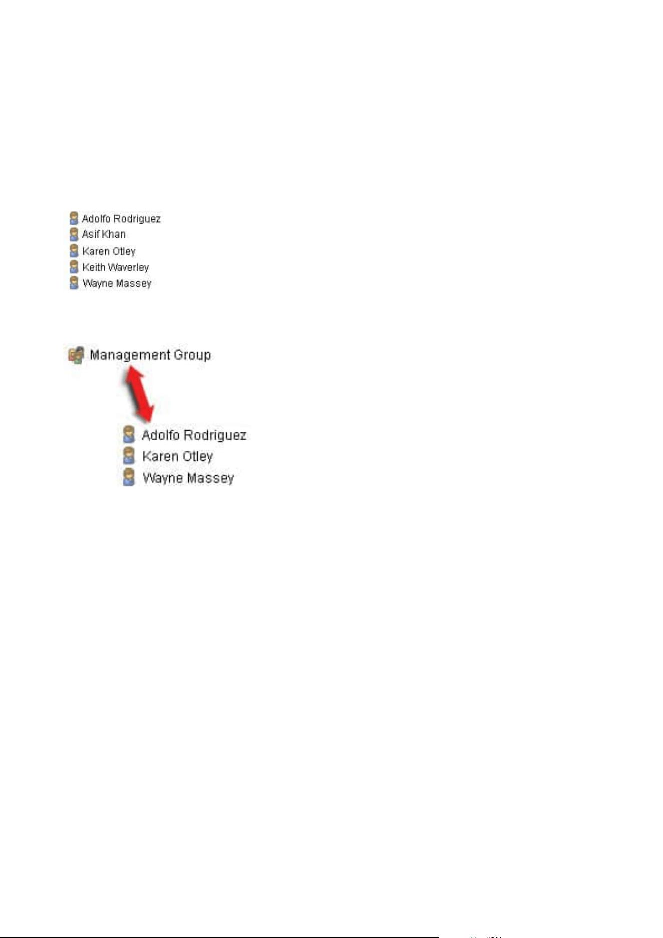
Windows Users
You add Windows Users through the use of Active Directory. Active Directory(AD) is a directory service
implemented by Microsoft for Windows domain networks. It is included in most Windows Server operating
systems. It identifies resources on a network in order for users or applications to access them. Active Directory
uses the concepts of users and groups.
Users are Active Directory objects representing individuals with a user account. Example:
Groups are Active Directory objects with several users. In this example, the Management Group has three
users:
Groups can contain any number of users. By adding a group to the system, you add all of its members in one
go. Once you have added the group to the system, any changes made to the group in Active Directory, such as
new members you add or old members you remove at a later stage, are immediately reflected in the system. A
user can be a member of more than one group at a time.
You can use Active Directory to add existing user and group information to the system with some benefits:
l
Users and groups are specified centrally in Active Directory so you do not have to create user accounts
from scratch
l
You do not have to configure any authentication of users on the system as Active Directory handles
authentication
Before you can add users and groups through the Active Directory service, you must have a server with Active
Directory installed on your network.
Basic users
If your system does not have access to Active Directory, create a basic user. For information about how to set
up basic users, see Create basic users on page 274.
Administrator manual | XProtect® VMS 2023 R1
62 | Overview

Identity Provider (explained)
Identity Provider app pool (IDP) is a system entity that creates, maintains, and manages identity information
for basic users.
Identity Provider also provides authentication and registration services to relying applications or services, in
this case: Recording Server, Management Server, Data Collector, and Report Server.
When you log in to XProtect clients and services as a basic user, your request goes to the Identity Provider.
When authenticated the user can call the management server.
Identity Provider runs in the IIS as a part of the management server using the same SQL Server with a separate
database and is responsible for creating and handling OAuth communication tokens that services use when
communicating (Surveillance_IDP).
Identity Provider logs can be found at: \\ProgramData\Milestone\IDP\Logs.
External IDP (explained)
IDP is an acronym for Identity Provider. An external IDP is an external application and service where you can
store and manage user identity information and provide user authentication services to other systems. You
can associate an external IDP with the XProtect VMS.
Claims (explained)
Claims form the link between the external IDP and the XProtect VMS.
A claim is a statement that an entity such as a user or an application makes about itself. In the XProtect VMS, a
claim can be associated with a role that determine the users' XProtect permissions.
The claim is a key value consisting of a claim name and a claim value. For example, the claim name could be a
standard name that describes the content of the claim value, and the claim value could be the name of a
group. See more example of claims from an external IDP: Example of claims from an external IDP.
Enable users to log in to the XProtect VMS from an external IDP
l
From the external IDP, create the users. You must also identify the XProtect VMS and the interaction
between XProtect and the external IDP. Finally, create the claims to identify users as external IDP users
in the XProtect VMS.
l
From the XProtect VMS, create a configuration that enables the Identity Provider to contact the external
IDP. For more information about how to create a configuration for an external IDP, see Add and
configure an external IDP.
l
From the XProtect VMS, establish authentication of users by mapping the user claims from the external
IDP to XProtect roles. For more information about how to map claims to roles, see Map claims from an
external IDP to roles in XProtect.
Unique user names for external IDP users
User names are created automatically for users that log into Milestone XProtect via an external IDP.
Administrator manual | XProtect® VMS 2023 R1
63 | Overview

The external IDP provides a set of claims to automatically create a name for the user in XProtect, and in
XProtect an algorithm is used to pick a name from the external IDP that is unique in the VMS database.
Example of claims from an external IDP
The claims consist of a claim name and a claim value. For example:
Claim name Claim value
name Raz Van
email [email protected]
amr pwd
idp 00o2ghkgazGgi9BIE5d7
preferred_
username
vmsRole Operator
locale en-US
given_name Raz
family_name Van
zoneinfo America/Los_Angeles
email_verified True
Using sequence number of claim to create user names in XProtect
In XProtect, the search priority for when creating a user in the XProtect VMS is controlled by the sequence
number of the claims in the table below. The first available claim name will be used in the XProtect VMS:
Administrator manual | XProtect® VMS 2023 R1
64 | Overview

Claim name Sequence number Description
UserNameClaimType 1
Configured mapping with one claim to define
the user name. The claim is defined in the
Claim to use to create user name field on
the External IDP tab under Tools > Options.
preferred_username 2
Claim that can come from the external IDP. A
standard claim that is normally used for this
in Oidc (OpenID Connect).
name 3
given_name family_
name
4
Given name and family name in a
combination such as Bob Johnson.
email 5
First available claim + #
(first available number)
6 For example, Bob#1
Defining specific claims to create user names in XProtect
The XProtect administrators can define a specific claim from the external IDP that should be used to create a
user name in the XProtect VMS. When an administrator define a claim to use for the creation of the user name
in the XProtect VMS, the claim name must be written exactly as the claim name coming from the external IDP.
l
The claim to use for the user name can be defined in the Claim to use to create user name field on the
External IDP tab under Tools > Options .
Deleting external IDP users
Users created in XProtect by an external IDP login are deleted the same way as a basic user and the user can
be deleted at any time after the user is created.
If a user is deleted in XProtect and the user logs in again from the external IDP, a new user will be created in
XProtect. However, the data associated with the user in XProtect such as private views and roles are lost and
this information has to be created again for the user in XProtect.
If an external IDP is deleted in the Management Client, any users connected to the VMS via the external IDP
are also deleted.
Administrator manual | XProtect® VMS 2023 R1
65 | Overview

Security
Roles and permissions of a role (explained)
Roles determine which devices users can access. Roles also determine permissions and handle security within
the video management system. First, you add roles, then you add users and groups and finally a Smart Client
and a Management Client profile as well as other default profiles that belong to each role. Roles you can create
in the system have their own view groups in XProtect Smart Client in which their views are created and stored.
It is important that all roles, to have access to the Management Server, enable the
Connect security permission, located in Role Settings > Management Server > Overall
Security tab (roles) on page 495.
You add users and groups to the Administrators role just as with any other role. See Assign/remove users and
groups to/from roles on page 273.
In addition to the Administrators role, you can add as many roles as required to suit your needs. You may, for
example, have different roles for users of XProtect Smart Client depending on which cameras you want them
to access or similar restrictions. To set up roles in your system, expand the Security > Roles.
Permissions of a role
Available functionality depends on the system you are using. See the complete feature list, which is available
on the product overview page on the Milestone website
(https://www.milestonesys.com/solutions/platform/product-index/).
When you create a role in your system, you can give the role a number of permissions to the system
components or features that the relevant role can access and use. You may, for example, want to create roles
that only have permissions to functionality in XProtect Smart Client or other Milestone viewing clients, with the
permissions to view only certain cameras. If you create such roles, these roles should not have permissions to
access and use the Management Client, but only have access to some or all functionality found in XProtect
Smart Client or other clients. To address this, you may want to set up a role that has some or most typical
administrator permissions, for example, the permissions to add and remove cameras, servers and similar
functionality.
You can create roles that have some or most permissions of a system administrator. This may, for example, be
relevant if your organization wants to separate between people who can administrate a subset of the system
and people who can administrate the entire system. The feature allows you to provide differentiated
administrator permissions to access, edit or change a large variety of system functions, for example, the
permission to edit the settings for servers or cameras in your system. You specify these permissions on the
Overall Security tab (see Overall Security tab (roles) on page 495). As a minimum, to enable that the
differentiated system administrator can launch the Management Client, you must grant read permissions on
the management server for the role.
Administrator manual | XProtect® VMS 2023 R1
66 | Overview
It is important that all roles, to have access to the Management Server, enable the
Connect security permission, located in Role Settings > Management Server > Overall
Security tab (roles) on page 495.
You can also reflect the same limitations in the user interface of the Management Client for each role by
associating the role with a Management Client profile that has the removed the corresponding system
functions from the user interface. See Management Client profiles (explained) on page 69 for information.
To give a role such differentiated administrator permissions, the person with the default full administrator role
must set up the role under Security > Roles > Info tab > Add new. When you set up the new role, you can then
associate the role with your own profiles must similarly to when you set up any other role in the system or use
the system's default profiles. For more information, see Add and manage a role on page 271.
Once you have specified what profiles you want to associate the role with, go to the Overall Security tab to
specify the permissions of the role.
The permissions you can set for a role are different between your products. You can only
give all available permissions to a role in XProtect Corporate.
Privacy masking (explained)
Privacy masking (explained)
With privacy masking, you can define which areas of the video from a camera you want to cover with privacy
masks when shown in the clients. For example, if a surveillance camera covers a street, you can cover certain
areas of a building (could be windows and doors) with privacy masks, to protect the privacy of residents. In
some countries, this is a legal requirement.
You can specify privacy masks as either solid or blurred. The masks cover both live, recorded, and exported
video.
Privacy masks are applied and locked to an area of the camera image, so the covered area does not follow the
pan-til-zoom movements, but constantly covers the same area of the camera image. On some PTZ cameras,
you can enable position based privacy masking on the camera itself.
There are two types of privacy masks:
l
Permanent privacy mask: Areas with this type of mask are always covered in the clients. Can be used
to cover areas of the video that never requires surveillance, like public areas, or areas where
surveillance is not allowed. Motion detection is excluded from areas with permanent privacy masks
Administrator manual | XProtect® VMS 2023 R1
67 | Overview
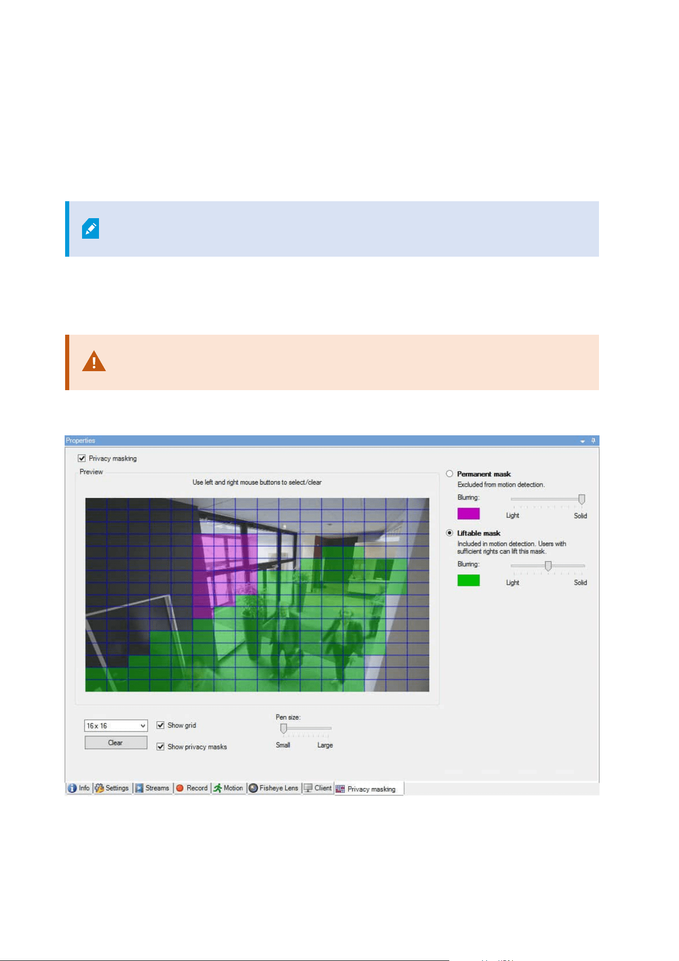
l
Liftable privacy mask: Areas with this type of mask can be temporarily uncovered in XProtect Smart
Client by users with permission to lift privacy masks. If the logged in XProtect Smart Client user does
not have the permission to lift privacy masks, the system asks for an authorized user to approve of the
lift.
Privacy masks are lifted until timeout or the user reapply them. Be aware that privacy masks are lifted
on video from all cameras that the user has access to
If you upgrade from a 2017 R3 system or older with privacy masks applied, the masks
will be converted to liftable masks.
When a user exports or playbacks recorded video from a client, the video includes the privacy masks
configured at the time of recording, even if you have changed or removed the privacy masks later. If privacy
protection is lifted when exporting, the exported video does not include the liftable privacy masks.
If you change privacy masking settings very often, for example once a week, your
system can potentially be overloaded.
Example of the Privacy masking tab with privacy masks configured:
And this is how they appear in the clients:
Administrator manual | XProtect® VMS 2023 R1
68 | Overview
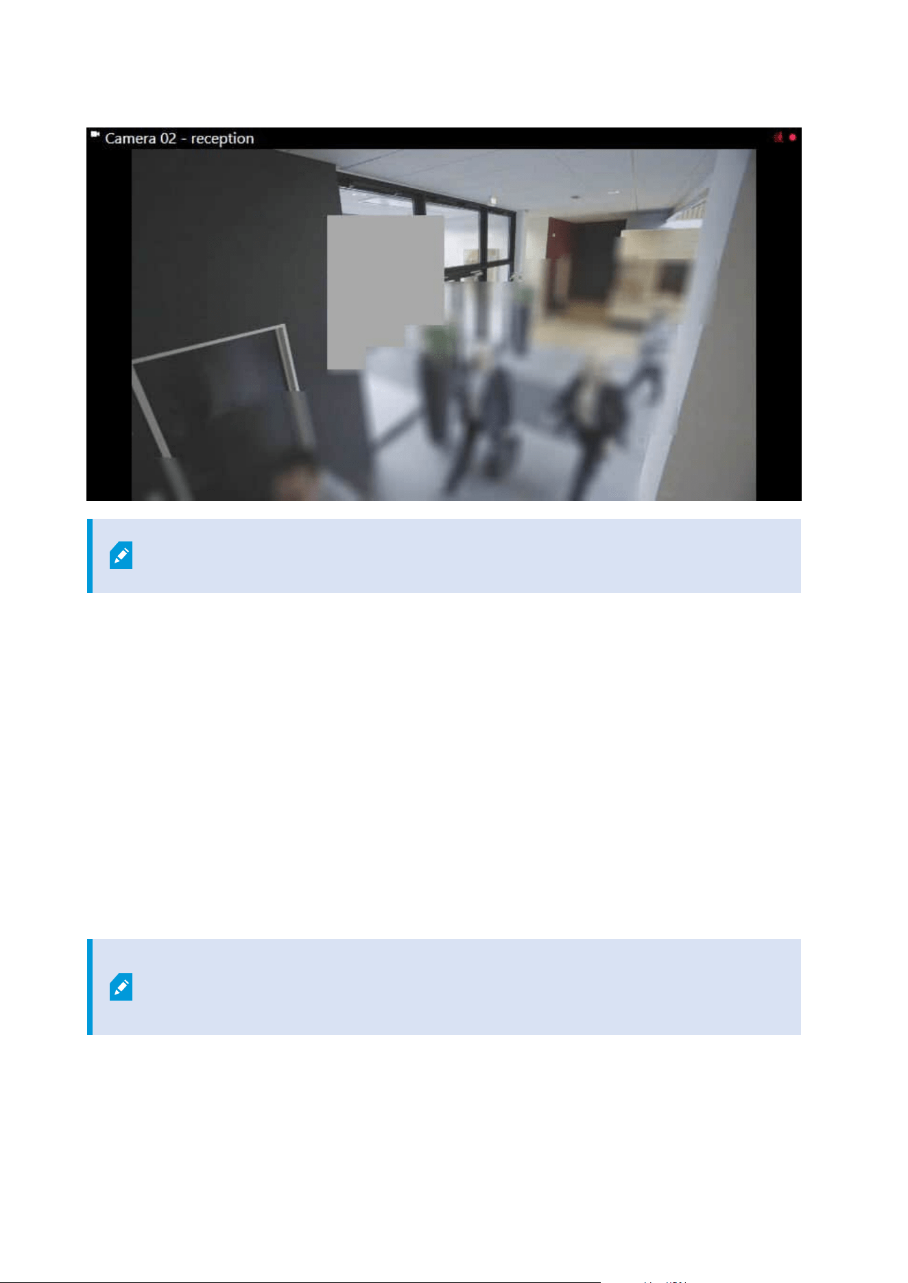
You can inform the client users about the settings of permanent and liftable privacy
masks.
Management Client profiles (explained)
Management Client profiles allow system administrators to modify the Management Client user interface for
other users. Associate Management Client profiles with roles to limit the user interface to represent the
functionality available for each administrator role.
Management Client profiles only handle the visual representation of system functionality, not the actual access
to it. The overall access to system functionality is granted via the role that individual users are associated with.
For information about how to manage overall access to system functionality for a role, see Manage the
visibility of functionality for a Management Client profile.
You can change settings for the visibility of all Management Client elements. By default, the Management
Client profile can see all functionality in the Management Client.
Smart Client profiles (explained)
Available functionality depends on the system you are using. See the complete feature
list, which is available on the product overview page on the Milestone website
(https://www.milestonesys.com/solutions/platform/product-index/).
Administrator manual | XProtect® VMS 2023 R1
69 | Overview

Smart Client profiles allows system administrators to control how XProtect Smart Client should look and
behave and what features and panes XProtect Smart Client users have access to. You can set up user
permissions for: panes and options, minimize/maximize options, inactivity time-control, remember password
or not, view shown after log in, layout of print reports, export path, and more.
To manage Smart Client profiles in the system, expand Client and select Smart Client Profiles.
You can also learn about the relationship between Smart Client profiles, roles and time profiles and how to use
these together (see Create and set up Smart Client profiles, roles and time profiles on page 249).
Evidence locks (explained)
Available functionality depends on the system you are using. See the complete feature
list, which is available on the product overview page on the Milestone website
(https://www.milestonesys.com/solutions/platform/product-index/).
As of XProtect VMS version 2020 R2, when you upgrade the management server from an
earlier version, it will not be possible to create or modify evidence locks on recording
servers that are version 2020 R1 or earlier, until these recording servers have been
upgraded.
This also means that if the hardware has been moved from one recording server (from
2020 R1 or earlier) to another recording server, and it still has recordings on it, then
evidence locks cannot be created or modified.
With the evidence lock functionality, client operators can protect video sequences, including audio and other
data, from deletion if required, for example, while an investigation or trial is ongoing. For more information,
see the user manual for XProtect Smart Client.
When protected, the data cannot be deleted, neither automatically by the system after the system's default
retention time or in other situations nor manually by the client users. The system or a user cannot delete the
data until a user with sufficient user permissions unlocks the evidence.
Flow diagram for Evidence Lock:
Administrator manual | XProtect® VMS 2023 R1
70 | Overview
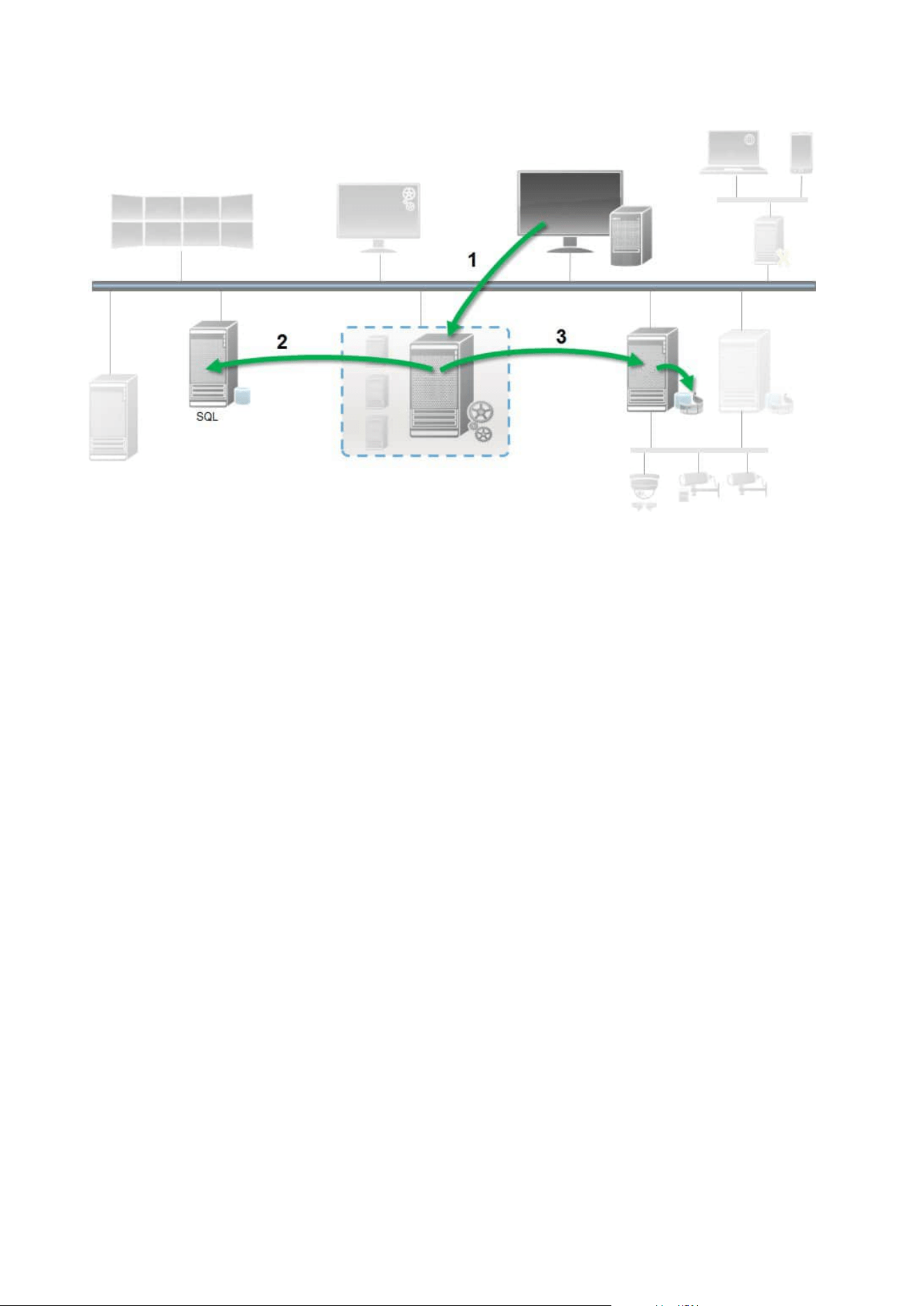
1. A XProtect Smart Client user creates an evidence lock. Information sent to Management Server.
2. Management Server stores information about the evidence lock in the SQL database.
3. Management Server informs Recording Server to store and protect the protected recordings in the
database.
When the operator creates an evidence lock, the protected data remains in the recording storage that it was
recorded to, and is moved to archiving disks together with non-protected data, but the protected data:
l
Follows the retention time configured for the evidence lock. Potentially infinitely
l
Keeps the original quality of the recordings, even if grooming has been configured for non-protected data
When an operator creates locks, the minimum size of a sequence is the period that the database divides
recorded files into, this is by default one-hour sequences. You can change this, but it requires that you
customize the RecorderConfig.xml file on the recording server. If a small sequence spans two one-hour
periods, the system locks the recordings in both periods.
In the audit log in the Management Client, you can see when a user creates, edits, or deletes evidence locks.
When a disk runs out of disk space, it does not impact the protected data. Instead, the oldest non-protected
data will be deleted. If there are no more non-protected data to delete, the system stops recording. You can
create rules and alarms triggered by disk full events, so you are automatically notified.
Except for more data being stored for a longer period and potentially affecting disk storage, the evidence lock
feature as such does not influence system performance.
If you move hardware (see Move hardware on page 324) to another recording server:
Administrator manual | XProtect® VMS 2023 R1
71 | Overview

l
Recordings protected by evidence locks remain on the old recording server with the retention time that
was defined when the evidence lock was created
l
The XProtect Smart Client user can still protect data with evidence locks on the recordings that were
made on a camera before it was moved to another recording server. Even if you move the camera
multiple times and the recordings are stored on multiple recording servers
By default, all operators have the default evidence lock profile assigned to them, but no user access
permissions to the feature. To specify the evidence lock access permissions of a role, see Device tab (roles) for
role settings. To specify the evidence lock profile of a role, see Info tab (roles) for role settings.
In the Management Client, you can edit the properties of the default evidence lock profile and create
additional evidence lock profiles and assign these to the roles instead.
Rules and events
Rules (explained)
Rules specify actions to carry out under particular conditions. Example: When motion is detected (condition), a
camera should begin recording (action).
The following are examples of what you can do with rules:
l
Start and stop recording
l
Set non-default live frame rate
l
Set non-default recording frame rate
l
Start and stop PTZ patrolling
l
Pause and resume PTZ patrolling
l
Move PTZ cameras to specific positions
l
Set output to activated/deactivated state
l
Send notifications via e-mail
l
Generate log entries
l
Generate events
l
Apply new device settings, for example a different resolution on a camera
l
Make video appear in Matrix recipients
l
Start and stop plug-ins
l
Start and stop feeds from devices
Administrator manual | XProtect® VMS 2023 R1
72 | Overview
Stopping a device means that video is no longer transferred from the device to the system, in which case you
cannot view live video nor record video. In contrast, a device on which you have stopped the feed can still
communicate with the recording server, and you can start the feed from the device automatically through a
rule, as opposed to when the device is manually disabled in the Management Client.
Some rule content may require that certain features are enabled for the relevant
devices. For example, a rule specifying that a camera should record does not work as
intended if recording is not enabled for the relevant camera. Before creating a rule,
Milestone recommends that you verify that the devices involved can perform as
intended.
Rule complexity
Your exact number of options depends on the type of rule you want to create, and on the number of devices
available on your system. Rules provide a high degree of flexibility: you can combine event and time
conditions, specify several actions in a single rule, and very often create rules covering several or all the
devices on your system.
You can make your rules as simple or complex as required. For example, you can create very simple time-
based rules:
Example Explanation
Very Simple Time-
Based Rule
On Mondays between 08.30 and 11.30 (time condition), Camera 1 and Camera 2
should start recording (action) when the time period begins and stop recording
(stop action) when the time period ends.
Very Simple Event-
Based Rule
When motion is detected (event condition) on Camera 1, Camera 1 should start
recording (action) immediately, then stop recording (stop action) after 10
seconds.
Even if an event-based rule is activated by an event on one device, you can
specify that actions should take place on one or more other devices.
Rule Involving
Several Devices
When motion is detected (event condition) on Camera 1, Camera 2 should start
recording (action) immediately, and the siren connected to Output 3 should
sound (action) immediately. Then, after 60 seconds, Camera 2 should stop
recording (stop action), and the siren connected to Output 3 should stop
sounding (stop action).
Administrator manual | XProtect® VMS 2023 R1
73 | Overview
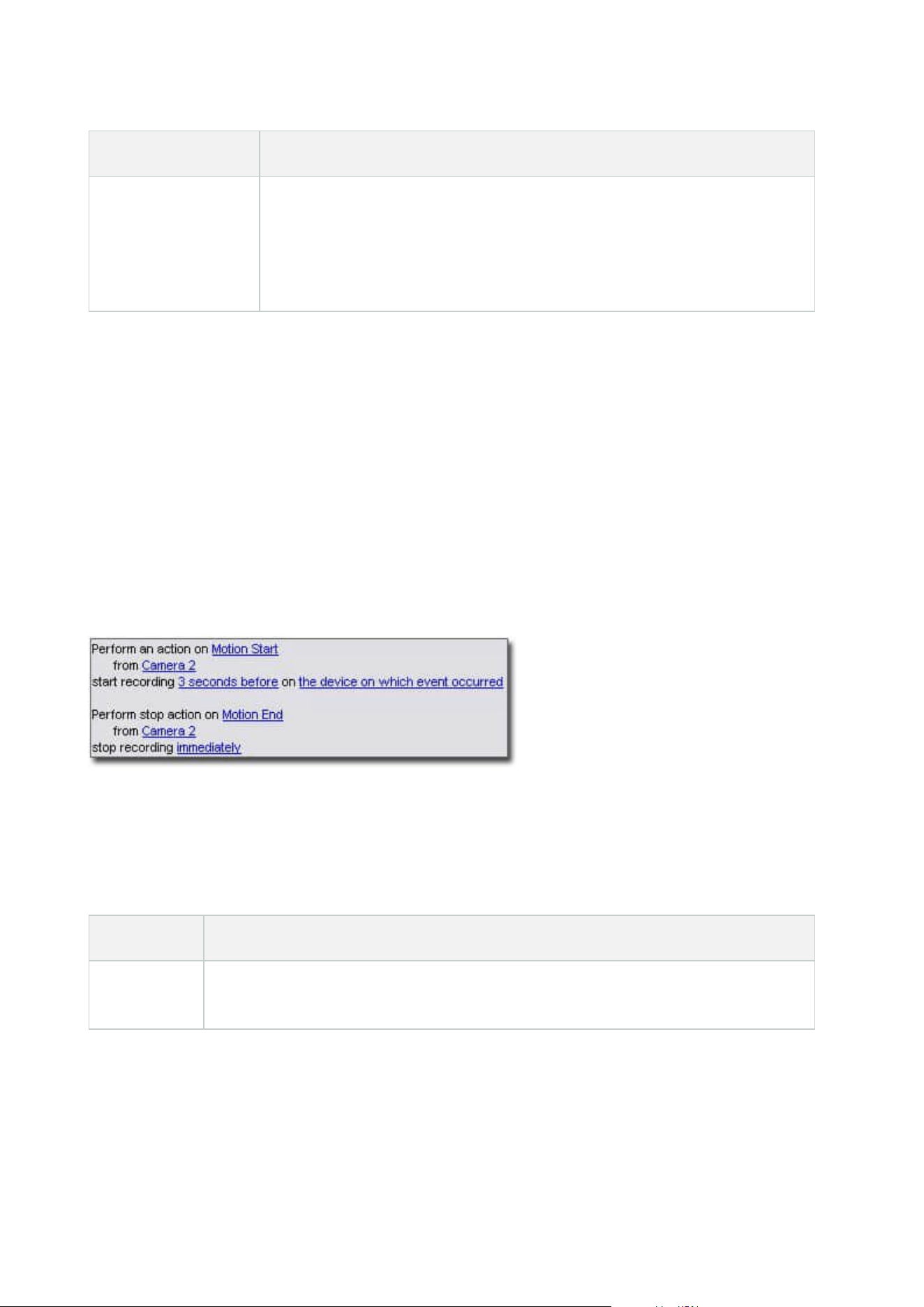
Example Explanation
Rule Combining
Time, Events, and
Devices
When motion is detected (event condition) on Camera 1, and the day of the week
is Saturday or Sunday (time condition), Camera 1 and Camera 2 should start
recording (action) immediately, and a notification should be sent to the security
manager (action). Then, 5 seconds after motion is no longer detected on Camera
1 or Camera 2, the 2 cameras should stop recording (stop action).
Depending on your organization's needs, it is often a good idea to create many simple rules rather than a few
complex rules. Even if it means you have more rules in your system, it provides an easy way to maintain an
overview of what your rules do. Keeping your rules simple also means that you have much more flexibility
when it comes to deactivating/activating individual rule elements. With simple rules, you can
deactivate/activate entire rules when required.
Rules and events (explained)
Rules are a central element in your system. Rules determine highly important settings, such as when cameras
should record, when PTZ cameras should patrol, when notifications should be sent, etc.
Example - a rule specifying that a particular camera should begin recording when it detects motion:
Events are central elements when using the Manage Rule wizard. In the wizard, events are primarily used for
triggering actions. For example, you can create a rule which specifies that in the event of detected motion, the
surveillance system should take the action of starting recording of video from a particular camera.
The following types of conditions can trigger rules:
Name Description
Events
When events occur on the surveillance system, for example when motion is detected or
the system receives input from external sensors.
Administrator manual | XProtect® VMS 2023 R1
74 | Overview
Name Description
Time interval
When you enter specific periods of time, for example:
Thursday 16th August 2007 from 07.00 to 07.59
or
every Saturday and Sunday
Failover time
interval
Periods of time where failover is active or inactive.
Recurring
time
When you set an action to be executed on a detailed, recurring schedule.
For example:
l
Every week on Tuesday every 1 hour(s) between 15:00 and 15:30
l
On day 15 every 3 month(s) at 11:45
l
Every day every 1 hour(s) between 15:00 and 19:00
The time is based on the local time settings of the server on which
Management Client is installed.
You can work with the following under Rules and Events:
l
Rules: Rules are a central element in the system. The behavior of your surveillance system is to a very
large extent determined by rules. When creating a rule, you can work with all types of events
l
Time profiles: Time profiles are periods of time defined in the Management Client. You use them when
you create rules in the Management Client, for example to create a rule which specifies that a certain
action should take place within a certain time profile
l
Notification profiles: You can use notification profiles to set up ready-made email notifications, which
can automatically be triggered by a rule, for example when a particular event occurs
l
User-defined events: User-defined events are custom-made events that makes it possible for users to
manually trigger events in the system or react to inputs from the system
l
Analytics events: Analytics events are data received from external third-party video content analysis
(VCA) providers. You can use analytics events as basis for alarms
l
Generic events: Generic events allow you to trigger actions in the XProtect event server by sending
simple strings via the IP network to your system
Administrator manual | XProtect® VMS 2023 R1
75 | Overview
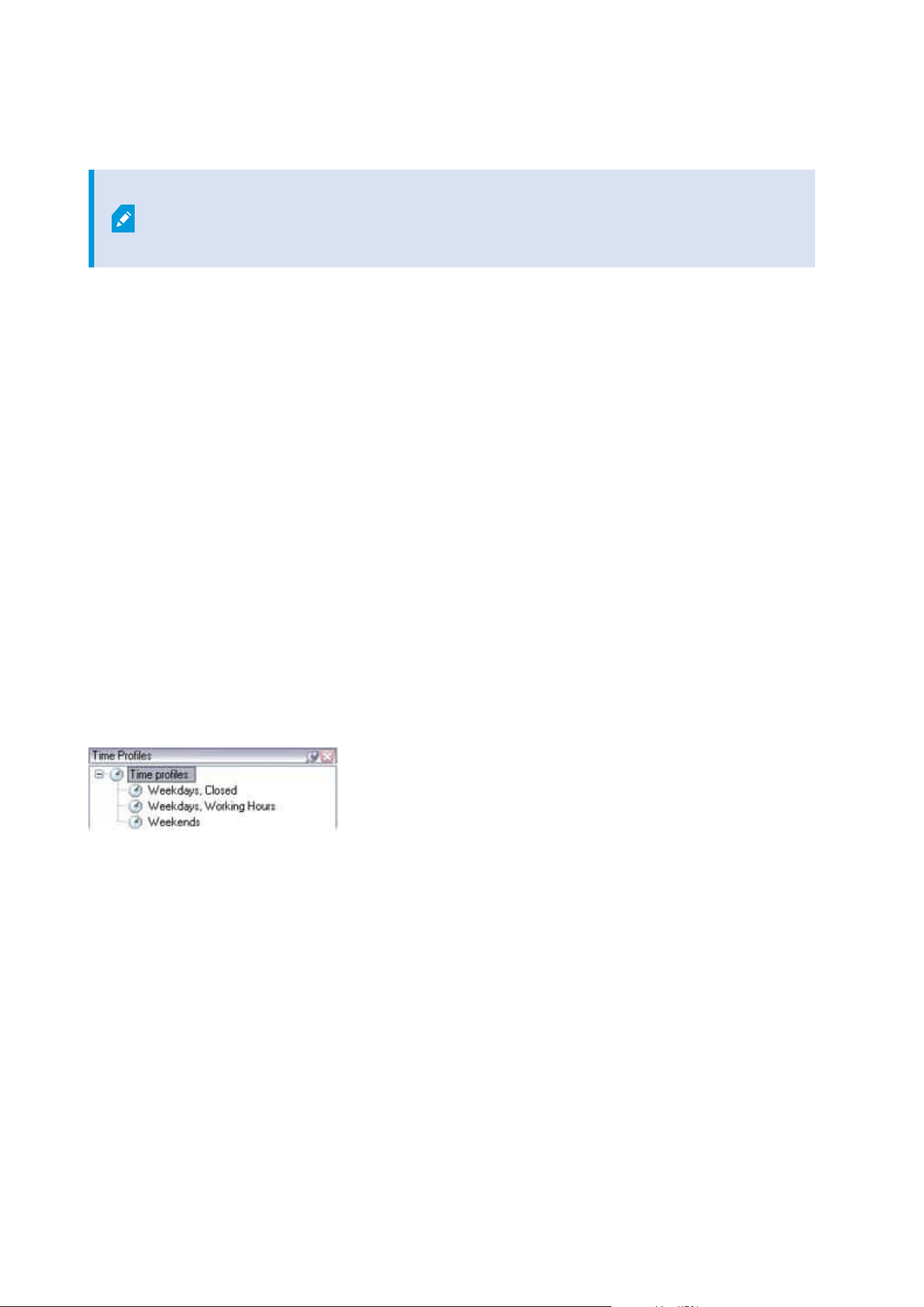
Time profiles (explained)
Available functionality depends on the system you are using. See the complete feature
list, which is available on the product overview page on the Milestone website
(https://www.milestonesys.com/solutions/platform/product-index/).
Time profiles are periods of time defined by the administrator. You can use time profiles when creating rules,
for example, a rule specifying that a certain action should take place within a certain time period.
Time profiles are also assigned to roles, along with Smart Client profiles. By default, all roles are assigned the
default time profile Always. This means that members of roles with this default time profile attached has no
time-based limits to their user permissions in the system. You can also assign an alternative time profile to a
role.
Time profiles are highly flexible: you can base them on one or more single periods of time, on one or more
recurring periods of time, or a combination of single and recurring times. Many users may be familiar with the
concepts of single and recurring time periods from calendar applications, such as the one in Microsoft
®
Outlook.
Time profiles always apply in local time. This means that if your system has recording servers placed in
different time zones, any actions, for example recording on cameras, associated with time profiles are carried
out in each recording server's local time. Example: If you have a time profile covering the period from 08.30 to
09.30, any associated actions on a recording server placed in New York is carried out when the local time is
08.30 to 09.30 in New York, while the same actions on a recording server placed in Los Angeles is carried out
some hours later, when the local time is 08.30 to 09.30 in Los Angeles.
You create and manage time profiles by expanding Rules and Events > Time Profiles. A Time Profiles list
opens. Example only:
For an alternative to time profiles, see Day length time profiles (explained).
Day length time profiles (explained)
When you place cameras outside, you must often lower the camera resolution, enable black/white or change
other settings when it gets dark or when it gets light. The further north or south from the equator the cameras
are placed, the more the sunrise and sunset time varies during the year. This makes it impossible to use
normal fixed time profiles to adjusts camera settings according to light conditions.
In such situations, you can create day length time profiles instead to define the sunrise and sunset in a
specified geographical area. Via geographic coordinates, the system calculates the sunrise and sunset time,
even incorporating daylight saving time on a daily basis. As a result, the time profile automatically follows the
Administrator manual | XProtect® VMS 2023 R1
76 | Overview
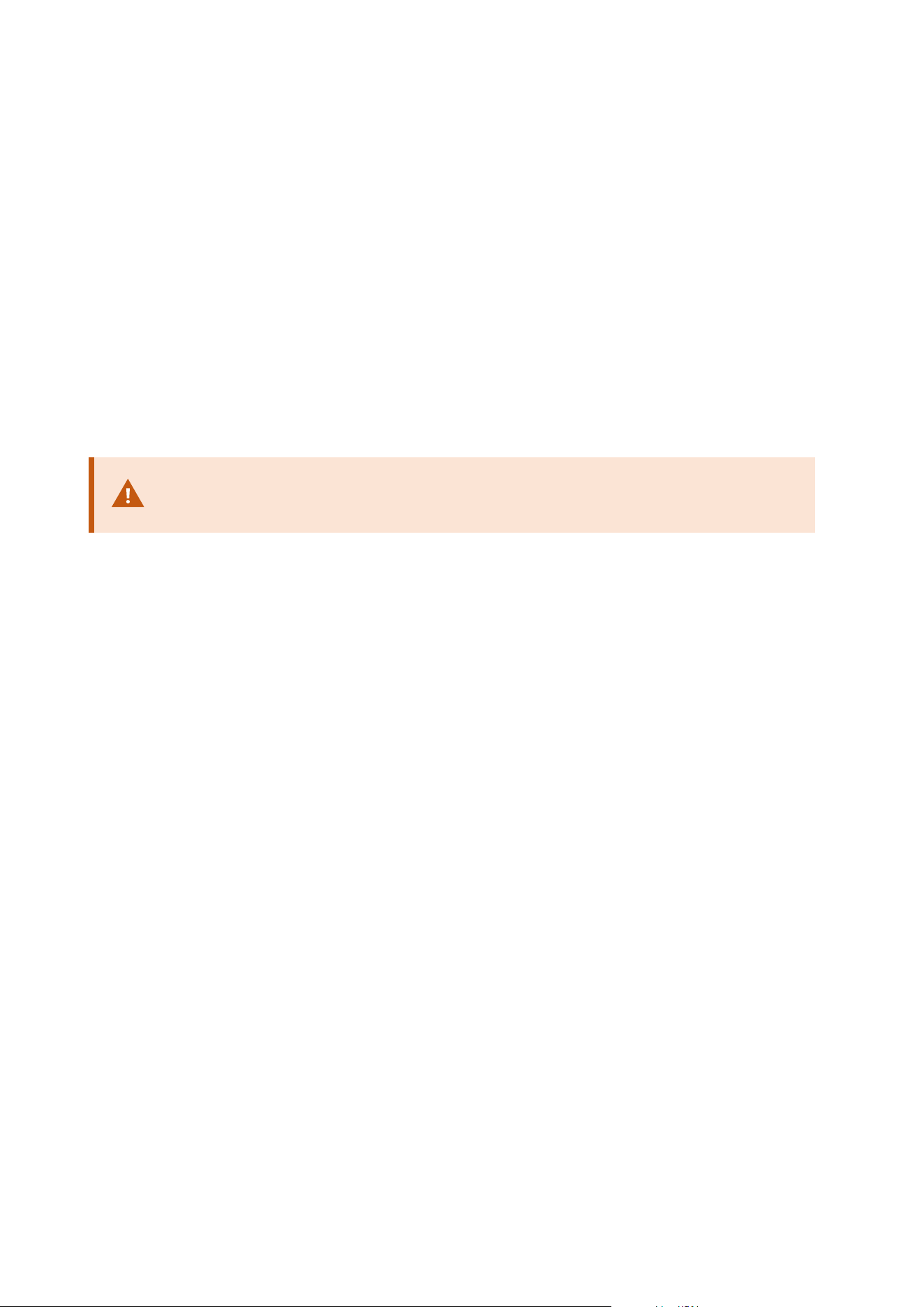
yearly changes in sunrise/sunset in the selected area, ensuring the profile to be active only when needed. All
times and dates are based on the management server's time and date settings. You can also set a positive or
negative offset (in minutes) for the start (sunrise) and end time (sunset). The offset for the start and the end
time can be identical or different.
You can use day length profiles both when you create rules and roles.
Notification profiles (explained)
Notification profiles allow you to set up ready-made email notifications. Notifications can automatically be
triggered by a rule, for example when a particular event occurs.
When you create the notification profile, you specify the message text and decides if you want to include still
images and AVI video clips in the email notifications.
You may need to disable any email scanners that could prevent the application from
sending email notifications.
Requirements for creating notification profiles
Before you can create notification profiles, you must specify mail server settings for email notifications.
You can secure the communication to the mail server, if you install the necessary security certificates on the
mail server.
If you want the email notifications to be able to include AVI movie clips, you must first specify the compression
settings:
1. Go to Tools > Options. This opens the Options window.
2. Configure the mail server on the Mail Server tab (Mail Server tab (options) on page 370) and the
compression settings on the AVI Generation tab AVI Generation tab (options) on page 371.
User-defined events (explained)
If the event you require is not on the Events Overview list, you can create your own user-defined events. Use
such user-defined events to integrate other systems with your surveillance system.
With user-defined events, you can use data received from a third-party access control system as events in the
system. The events can later trigger actions. This way, you can, for example, begin recording video from
relevant cameras when somebody enters a building.
You can also use user-defined events for manually triggering events while viewing live video in XProtect Smart
Client or automatically if you use them in rules. For example, when user-defined event 37 occurs, PTZ camera
224 should stop patrolling and go to preset position 18.
Administrator manual | XProtect® VMS 2023 R1
77 | Overview

Through roles, you define which of your users are able to trigger the user-defined events. You can use user-
defined events in two ways and at the same time if required:
Events Description
For providing the
ability to manually
trigger events in
XProtect Smart
Client
In this case, user-defined events make it possible for end users to manually
trigger events while viewing live video in XProtect Smart Client. When a user-
defined event occurs because a user of XProtect Smart Client triggers it manually,
a rule can trigger that one or more actions should take place on the system.
For providing the
ability to trigger
events through API
In this case, you can trigger user-defined events outside the surveillance system.
Using user-defined events this way requires that a separate API (Application
Program Interface. A set of building blocks for creating or customizing software
applications) is used when triggering the user-defined event. Authentication
through Active Directory is required for using user-defined events this way. This
ensures that even if the user-defined events can be triggered from outside the
surveillance system, only authorized users are to do it.
Also, user-defined events can via API be associated with meta-data, defining
certain devices or device groups. This is highly usable when using user-defined
events to trigger rules: you avoid having a rule for each device, basically doing
the same thing. Example: A company uses access control, having 35 entrances,
each with an access control device. When an access control device is activated, a
user-defined event is triggered in the system. This user-defined event is used in a
rule to start recording on a camera associated with the activated access control
device. It is defined in the meta-data which camera is associated with what rule.
This way the company does not need to have 35 user-defined events and 35 rules
triggered by the user-defined events. A single user-defined event and a single
rule are enough.
When you use user-defined events this way, you may not always want them to be
available for manual triggering in XProtect Smart Client. You can use roles to
define which user-defined events should be visible in XProtect Smart Client.
Analytics events (explained)
Analytics events are typically data received from an external third-party video content analysis (VCA) provider.
Using analytics events as basis for alarms is basically a three step process:
Administrator manual | XProtect® VMS 2023 R1
78 | Overview

l
Part one, enabling the analytics events feature and setting up its security. Use a list of allowed
addresses to control who can send event data to the system and which port the server listens on
l
Part two, creating the analytics event, possibly with a description of the event, and testing it
l
Part three, using the analytics event as the source of an alarm definition
You set up analytics events on the Rules and Events list in the Site Navigation pane.
To use VCA-based events, a third-party VCA tool is required for supplying data to the system. Which VCA tool to
use is entirely up to you, as long as the data supplied by the tool adheres to the format. This format is
explained in the MIP SDK Documentation on analytics events.
Contact your system provider for more details. Third-party VCA tools are developed by independent partners
delivering solutions based on a Milestone open platform. These solutions can impact performance on the
system.
Generic events (explained)
Generic events allow you to trigger actions in the XProtect event server by sending simple strings via the IP
network to your system.
You can use any hard- or software, which can send strings via TCP or UDP, to trigger generic events. Your
system can analyze received TCP or UDP data packages, and automatically trigger generic events when specific
criteria are met. This way, you may integrate your system with external sources, for example access control
systems and alarm systems. The aim is to allow as many external sources as possible to interact with the
system.
With the concept of data sources, you avoid having to adapt third-party tools to meet the standards of your
system. With data sources, you can communicate with a particular piece of hard- or software on a specific IP
port and fine-tune how bytes arriving on that port are interpreted. Each generic event type pairs up with a data
source and makes up a language used for communication with a specific piece of hard- or software.
Working with data sources requires general knowledge of IP networking and specific knowledge of the
individual hard- or software you want to interface from. There are many parameters you can use and no ready-
made solution on how to do this. Basically, your system provides the tools, but not the solution. Unlike user-
defined events, generic events have no authentication. This makes them easier to trigger but, to avoid
jeopardizing security, only events from local host are accepted. You can allow other client IP addresses from
the Generic Events tab of the Options menu.
Alarms
Alarms (explained)
This feature only works if you have XProtect Event Server installed.
This article describes how to set up alarms to appear in the system, triggered by events.
Administrator manual | XProtect® VMS 2023 R1
79 | Overview
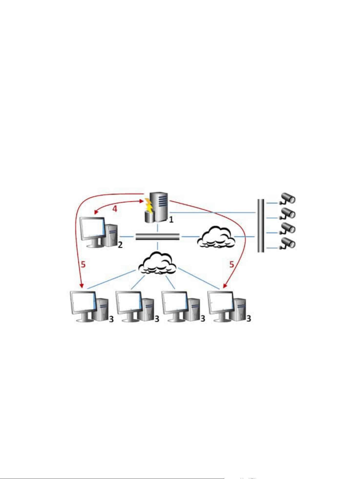
Based on functionality handled in the event server, the alarms feature provides central overview, control and
scalability of alarms in any number of installations (including any other XProtect systems) throughout your
organization. You can configure it to generate alarms based on either:
l
Internal system related events
For example, motion, server responding/not responding, archiving problems, lack of disk space and
more.
l
External integrated events
This group consist of several types of external events:
l
Analytics events
Typically data received from an external third-party video content analysis (VCA) providers.
l
MIP plug-in events
Through the MIP SDK a third-party vendor can develop custom plug-ins (for example, integration
to external access control systems or similar) to your system.
Legend:
1. Surveillance system
2. Management Client
3. XProtect Smart Client
4. Alarm configuration
5. Alarm data flow
Administrator manual | XProtect® VMS 2023 R1
80 | Overview

You handle and delegate alarms in the alarm list in XProtect Smart Client. You can also integrate alarms with
the XProtect Smart Client's smart map and map functionality.
Alarm configuration
Alarm configuration includes:
l
Dynamic role-based setup of alarm handling
l
Central technical overview of all components: servers, cameras, and external units
l
Setup of central logging of all incoming alarms and system information
l
Handling of plug-ins, allowing customized integration of other systems, for example external access
control or VCA-based systems
In general, alarms are controlled by the visibility of the object causing the alarm. This means that four possible
aspects can play a role with regards to alarms and who can control/manage them and to what degree:
Name Description
Source/device
visibility
If the device causing the alarm is not set to be visible to the user's role, the user
cannot see the alarm in the alarm list in XProtect Smart Client.
The right to trigger
user-defined events
This permission determines if the user's role can trigger selected user-defined
events in XProtect Smart Client.
External plug-ins
If any external plug-ins are set up in your system, these might control users'
permissions to handle alarms.
General role rights
Determine whether the user is allowed to only view or also to manage alarms.
What a user of Alarms can do with alarms depends on the user's role and on
settings configured for that particular role.
On the Alarms and Events tab in Options, you can specify settings for alarms, events and logs.
Smart map
Smart map (explained)
In XProtect® Smart Client, the smart map feature lets you view and access devices at multiple locations around
the world in a geographically correct way. Unlike maps, where you had a different map for each location, smart
map gives you the big picture in a single view.
Administrator manual | XProtect® VMS 2023 R1
81 | Overview

The following configuration of the smart map feature is done in Management Client:
l
Configure the geographic backgrounds that you can choose for your smart map. This includes
integrating your smart map with one of the following services:
l
Bing Maps
l
Google Maps
l
Milestone Map Service
l
OpenStreetMap
l
Enable Bing Maps or Google Maps in XProtect Management Client or in XProtect Smart Client
l
Enable editing of smart maps, including devices, in XProtect Smart Client
l
Position your devices geographically in XProtect Management Client
l
Set up your smart map with Milestone Federated Architecture
Smart map integration with Google Maps (explained)
To embed Google Maps into your smart map, you need a Maps Static APIkey from Google. To get the APIkey,
first you must create a Google Cloud billing account. You are billed in accordance with the volume of map
loads per month.
Once you have the APIkey, you must enter it in XProtect Management Client. See also Enable Bing Maps or
Google Maps in Management Client on page 306.
For more information, see:
l
Google Maps Platform - get started:https://cloud.google.com/maps-platform/
l
Guide to Google Maps Platform
billing:https://developers.google.com/maps/billing/gmp-billing
l
Developer guide for Maps Static
API:https://developers.google.com/maps/documentation/maps-static/dev-guide
Add digital signature to Maps Static APIkey
If you expect the XProtect Smart Client operators to make more than 25,000 maps requests per day, you need
a digital signature for your Maps Static API key. The digital signature allows the Google servers to verify that
any site generating requests using your API key is authorized to do so. However, regardless of the usage
requirements, Google recommends using a digital signature as an additional security layer. To get the digital
signature, you must retrieve a URLsigning secret. For more information, see
https://developers.google.com/maps/documentation/maps-static/get-api-key#dig-sig-manual.
Administrator manual | XProtect® VMS 2023 R1
82 | Overview
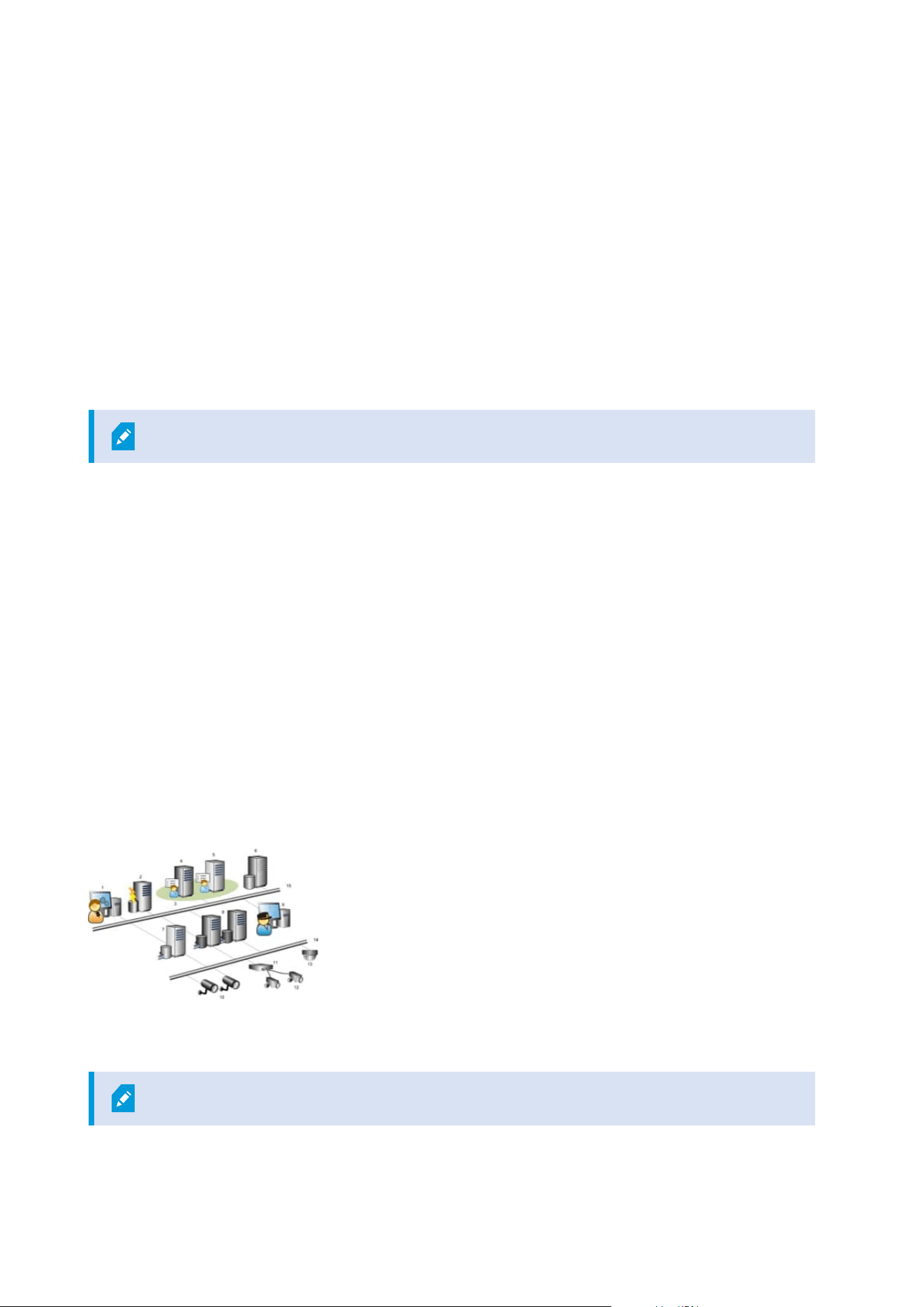
Smart map integration with Bing Maps (explained)
To embed Bing Maps into your smart map, you need a Basic Key or an Enterprise Key. The difference is that
basic keys are free, but allow a limited number of transactions before the transactions become billable or
access to the map service is denied. The enterprise key is not free, but allow an unrestricted number of
transactions.
For more information about Bing Maps, see https://www.microsoft.com/en-us/maps/licensing/.
Once you have the APIkey, you must enter it in XProtect Management Client. See Enable Bing Maps or Google
Maps in Management Client on page 306.
Cached smart map files (explained)
If you are using Google Maps as your geographic background, files are not cached.
The files that you use for your geographic background are retrieved from a tile server. The time that the files
are stored in the cache folder depends on the value selected in the Removed cached smart map files list in
the Settings dialog in XProtect Smart Client. The files are stored either:
l
Indefinitely (Never)
l
For 30 days if the file is not used (When not used for 30 days)
l
When the operator exits XProtect Smart Client (On exit)
When you change the tile server address, automatically a new cache folder is created. The previous map files
are retained in the associated cache folder on your local computer.
Architecture
A distributed system setup
Example of a distributed system setup. The number of cameras, recording servers, and connected clients, can
be as high as you require.
All computers in a distributed setup must either be on a domain or in a workgroup.
Administrator manual | XProtect® VMS 2023 R1
83 | Overview

Legend:
1. Management Client(s)
2. Event server
3. Microsoft cluster
4. Management server
5. Failover management server
6. Server with SQL Server
7. Failover recording server
8. Recording server(s)
9. XProtect Smart Client(s)
10. IP video cameras
11. Video encoder
12. Analog cameras
13. PTZ IP camera
14. Camera network
15. Server network
Milestone Interconnect (explained)
Available functionality depends on the system you are using. See the complete feature
list, which is available on the product overview page on the Milestone website
(https://www.milestonesys.com/solutions/platform/product-index/).
Milestone Interconnect™ allows you to integrate a number of smaller, physically fragmented, and remote
XProtect installations with one XProtect Corporate central site. You can install these smaller sites, called
remote sites, on mobile units, for example, boats, busses or trains. This means that such sites do not need to
be permanently connected to a network.
The following illustration shows how you could set up Milestone Interconnect on your system:
Administrator manual | XProtect® VMS 2023 R1
84 | Overview
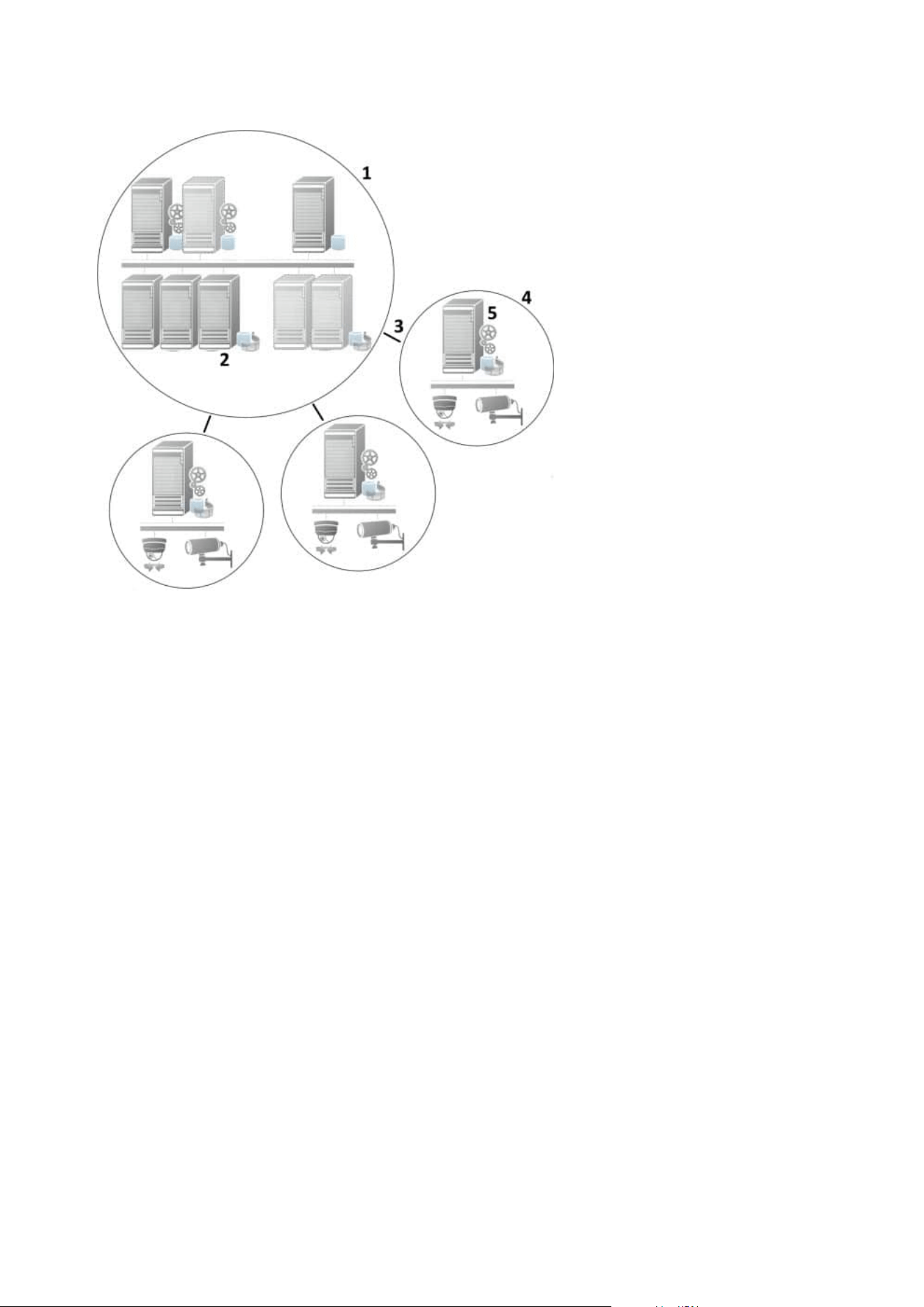
1. Milestone Interconnect central XProtect Corporate site
2. Milestone Interconnect drivers (handles the connection between the central sites' recording servers and
the remote site, must be selected in the list of drivers when adding remote systems via the Add
Hardware wizard)
3. Milestone Interconnect connection
4. Milestone Interconnect remote site (the complete remote site with system installation, users, cameras
and so on)
5. Milestone Interconnect remote system (the actual technical installation at the remote site)
You add remote sites to your central site with the Add Hardware wizard from the central site (see Add a
remote site to your central Milestone Interconnect site on page 299).
Each remote site runs independently and can perform any normal surveillance tasks. Depending on the
network connections and appropriate user permissions (see Assign user permissions on page 299), Milestone
Interconnect offers you direct live viewing of remote site cameras and play back of remote site recordings on
the central site.
The central site can only see and access devices that the specified user account (when adding the remote site)
has access to. This allows local system administrators to control which devices should be made available to the
central site and its users.
Administrator manual | XProtect® VMS 2023 R1
85 | Overview

On the central site, you can view the system's own status for the interconnected cameras, but not directly the
state of the remote site. Instead, to monitor the remote site, you can use the remote site events to trigger
alarms or other notifications on the central site (see Configure your central site to respond to events from
remote sites on page 301).
It also offers you the possibility to transfer remote site recordings to the central site based on either events,
rules/schedules, or manual requests by XProtect Smart Client users.
Only XProtect Corporate systems can work as central sites. All other products can act as remote sites including
XProtect Corporate. It differs from setup to setup which versions, how many cameras, and how devices and
events originating from the remote site are handled - if at all - by the central site. For further details on how
specific XProtect products interact in a Milestone Interconnect setup, go to the Milestone Interconnect website
(https://www.milestonesys.com/solutions/hardware-and-add-ons/milestone-addons/interconnect/).
Selecting Milestone Interconnect or Milestone Federated Architecture (explained)
In a physically distributed system where users on the central site need to access the video on the remote site,
you can choose between Milestone Interconnect™ or Milestone Federated Architecture™.
Milestone recommends Milestone Federated Architecture when:
l
The network connection between the central and federated sites is stable
l
The network uses the same domain
l
There are fewer larger sites
l
The bandwidth is sufficient for the required use
Milestone recommends Milestone Interconnect when:
l
The network connection between the central and remote sites is unstable
l
You or your organization want to use another XProtect product on the remote sites
l
The network uses different domains or workgroups
l
There are many smaller sites
Milestone Interconnect and licensing
To run Milestone Interconnect, you need Milestone Interconnect camera licenses on your central site to view
video from hardware devices on remote sites. The number of required Milestone Interconnect camera licenses
depends on the number of hardware devices on the remote sites that you want to receive data from. Only
XProtect Corporate can act as a central site.
The status of your Milestone Interconnect camera licenses are listed on the License Information page of the
central site.
Milestone Interconnect setups (explained)
There are three ways to run Milestone Interconnect. How to run your setup depends on your network
connection, how to play back recordings, and whether you retrieve remote recordings and to what degree.
Administrator manual | XProtect® VMS 2023 R1
86 | Overview

In the following, the three most likely setups are described:
Direct playback from remote sites (good network connections)
The most straightforward setup. The central site is continuously online with its remote sites and the central site
users play back remote recordings directly from the remote sites. This requires use of the Play back
recordings from remote system option (see Enable playback directly from remote site camera on page 300).
Rule- or XProtect Smart Client-based retrieval of selected remote recording sequences from remote
sites (periodically limited network connections)
Used when selected recording sequences (originating from remote sites) should be stored centrally to ensure
independence from remote sites. Independence is crucial in case of network failure or network restrictions.
You configure remote recordings retrieval settings on the Remote Retrieval tab (see Remote Retrieval tab on
page 412).
Remote recordings retrieval can be started from the XProtect Smart Client when needed or a rule can be set
up. In some scenarios, remote sites are online and in others, offline most of the time. This is often industry
specific. For some industries it is common for the central site to be permanently online with its remote sites
(for example a retail HQ (central site) and a number of shops (remote sites)). For other industries, like
transportation, the remote sites are mobile (for example, busses, trains, ships, and so on) and can only
establish network connection randomly. Should the network connection fail during a commenced remote
recording retrieval, the job continues at next given opportunity.
If the system detects an automatic retrieval, or request for retrieval from the XProtect Smart Client, outside the
time interval that you specified on the Remote Retrieval tab, it is accepted, but not started until the selected
time interval is reached. New remote recording retrieval jobs will queue and start when the allowed time
interval is reached. You can view pending remote recording retrieval jobs from System Dashboard -> Current
Tasks.
After connection failure, missing remote recordings are by default retrieved from remote sites
Uses remote sites like a recording server uses the edge storage on a camera. Typically, remote sites are online
with their central site, feeding it a live stream that the central site records. Should the network fail for some
reason, the central site misses out on recording sequences. However, once the network is reestablished, the
central site automatically retrieves remote recordings covering the down-period. This requires use of the
Automatically retrieve remote recordings when connection is restored option (see Retrieve remote
recordings from remote site camera on page 300) on the Record tab for the camera.
You can mix any of the above solutions to fit your organizations special needs.
Configuring Milestone Federated Architecture
XProtect Expert can only be federated as child sites.
Administrator manual | XProtect® VMS 2023 R1
87 | Overview
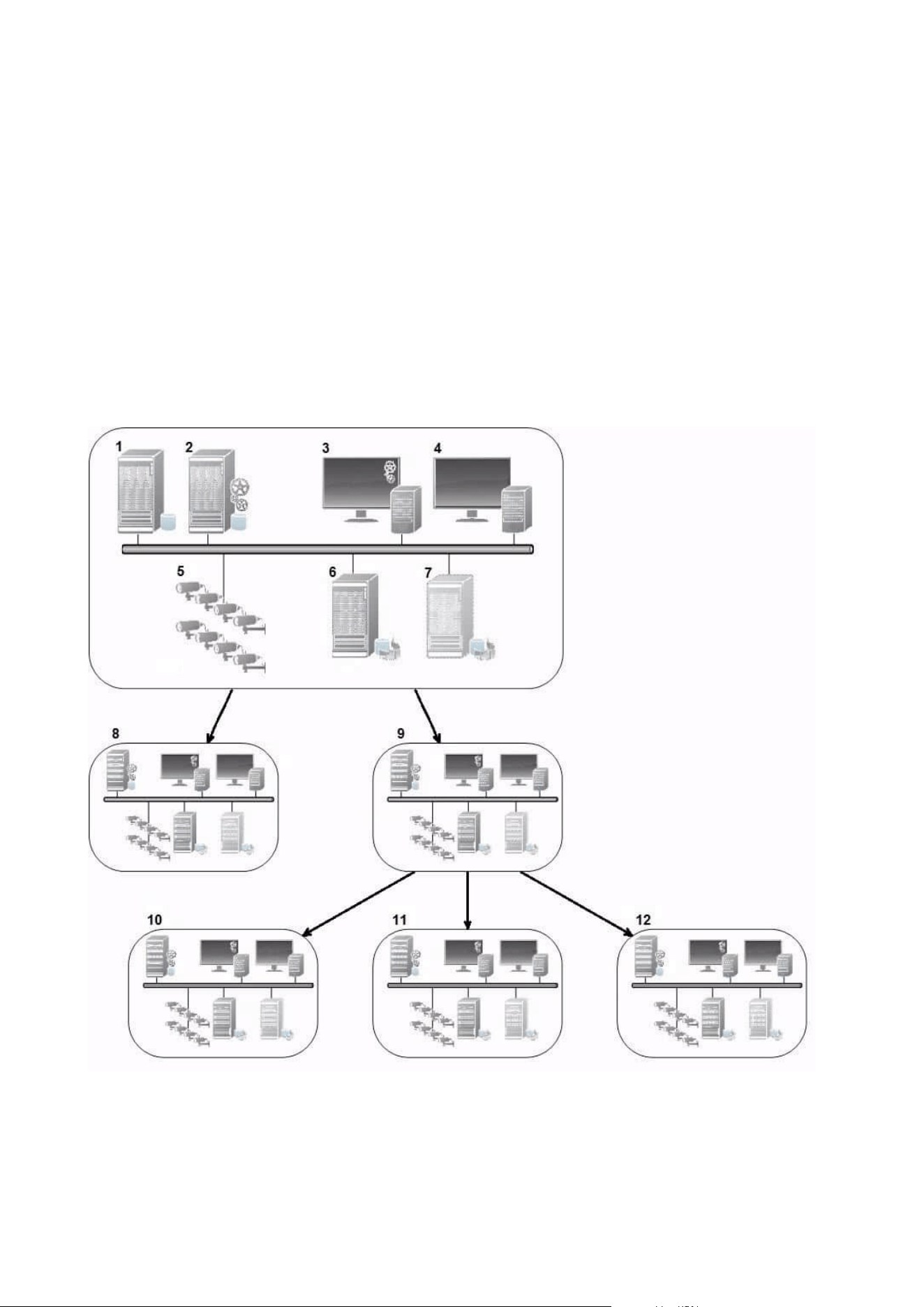
Milestone Federated Architecture links multiple individual standard systems into a federated site hierarchy of
parent/child sites. Client users with sufficient permissions have seamless access to video, audio and other
resources across individual sites. Administrators can centrally manage all sites from version 2018 R1 and
newer within the federated hierarchy, based on administrator permissions for the individual sites.
Basic users are not supported in Milestone Federated Architecture systems, so you must add users as Windows
users through the Active Directory service.
Milestone Federated Architecture is set up with one central site (top site) and an unrestricted number of
federated sites (see Set up your system to run federated sites on page 293). When you are logged into a site,
you can access information about all of its child sites and the child sites' child sites. The link between two sites
is established, when you request the link from the parent site (see Add site to hierarchy on page 295). A child
site can only be linked to one parent site. If you are not the administrator of the child site when you add it to
the federated site hierarchy, the request must be accepted by the child site administrator.
The components of a Milestone Federated Architecture setup:
Administrator manual | XProtect® VMS 2023 R1
88 | Overview

1. Server with SQL Server
2. Management server
3. Management Client
4. XProtect Smart Client
5. Cameras
6. Recording server
7. Failover recording server
8. to 12. Federated sites
Hierarchy synchronization
A parent site contains an updated list of all its currently attached child sites, child sites' child sites and so on.
The federated site hierarchy has a scheduled synchronization between sites, as well as a synchronization every
time a site is added or removed by the system administrator. When the system synchronizes the hierarchy, it
takes place level by level, each level forwarding and returning communication, until it reaches the server that
requests the information. The system sends less than 1MB each time. Depending on the number of levels,
changes to a hierarchy can take some time to become visible in the Management Client. You cannot schedule
your own synchronizations.
Data traffic
The system sends communication or configuration data when a user or administrator views live or recorded
video or configures a site. The amount of data depends on what and how much is being viewed or configured.
Milestone Federated Architecture with other products and system requirements
l
Opening the Management Client in a Milestone Federated Architecture is supported for three major
releases, including the current one being released. In a Milestone Federated Architecture setup beyond
that scope, you need a separate Management Client that matches the server version.
l
If the central site uses XProtect Smart Wall, you can also use the XProtect Smart Wall features in the
federated site hierarchy.
See also the manual for XProtect Smart Wall.
l
If the central site uses XProtect Access and XProtect Smart Client user logs into a site in a federated site
hierarchy, access request notifications from the federated sites also appear in XProtect Smart Client
l
You can add XProtect Expert 2013 systems or newer to the federated site hierarchy as child sites, not as
parent sites
Administrator manual | XProtect® VMS 2023 R1
89 | Overview
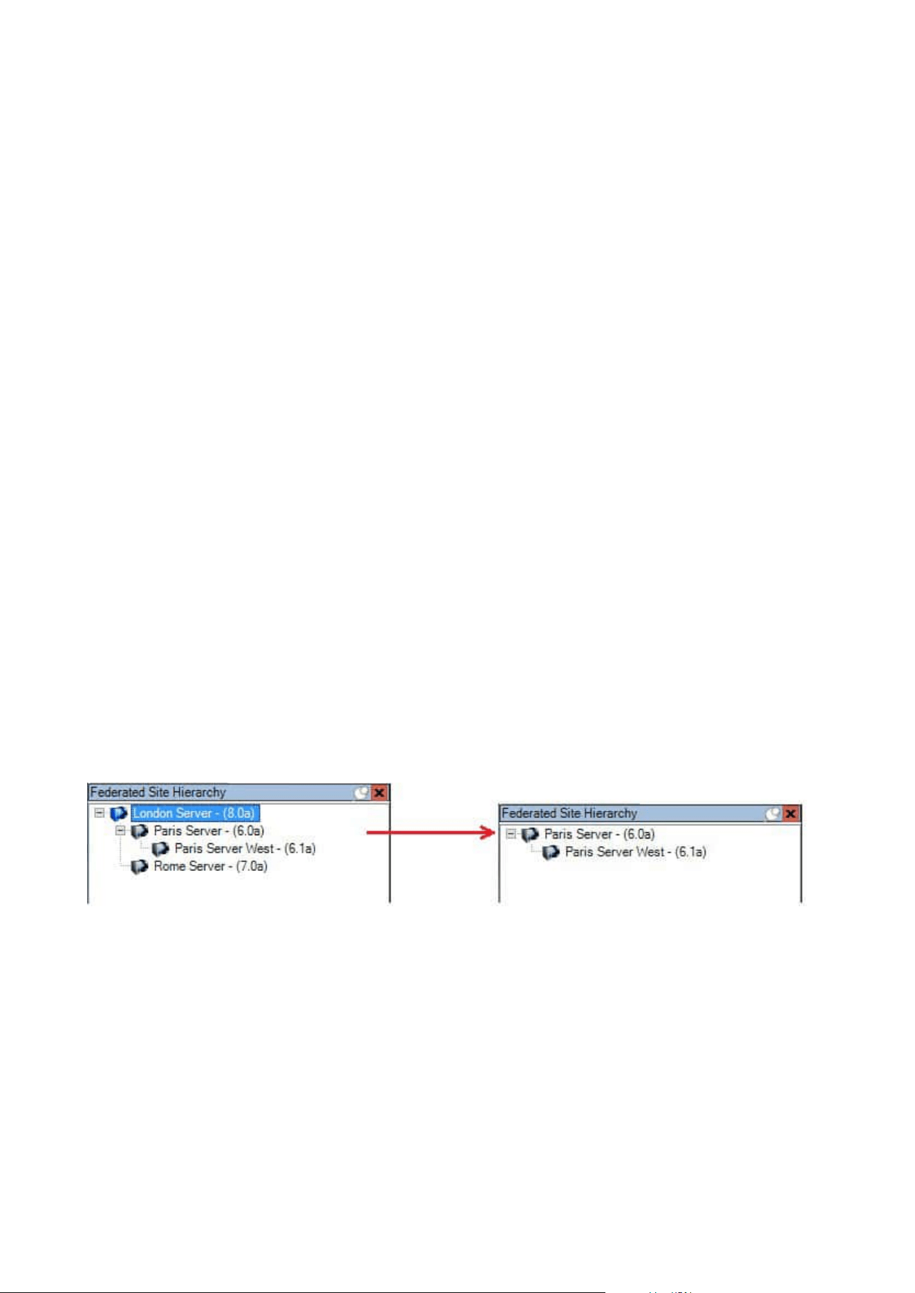
l
Milestone Federated Architecture does not require additional licenses
l
For more information about use cases and benefits, see the white paper about Milestone Federated
Architecture.
Establishing a federated site hierarchy
Before you start building up the hierarchy in the Management Client, Milestone recommends that you map
how you want your sites to link together.
You install and configure each site in a federated hierarchy as a normal standalone system with standard
system components, settings, rules, schedules, administrators, users, and user permissions. If you already
have the sites installed and configured and only need to combine them in a federated site hierarchy, your
systems are ready to be set up.
Once the individual sites are installed, you must set them up to run as federated sites (see Set up your system
to run federated sites on page 293).
To start the hierarchy, you can log into the site that you want to work as the central site and add (see Add site
to hierarchy on page 295) the first federated site. When the link is established, the two sites automatically
create a federated site hierarchy in the Federated Site Hierarchy pane in the Management Client to which you
can add more sites to grow the federated hierarchy.
When you have created a federated site hierarchy, users and administrators can log into a site to access that
site and any federated sites it may have. Access to federated sites depend on the user permissions.
There is no limit to the number of sites you can add to the federated hierarchy. Also, you can have a site on an
older product version linked to a newer version and vice versa. The version numbers appear automatically and
cannot be deleted. The site that you are logged into is always at the top of the Federated Site Hierarchy pane
and is called home site.
Below is an example of federated sited in the Management Client. To the left, the user has logged into the top
site. To the right, the user has logged into one of the child sites, the Paris Server, which is then the home site.
Status icons in Milestone Federated Architecture
The icons represent the possible states of a site:
Administrator manual | XProtect® VMS 2023 R1
90 | Overview
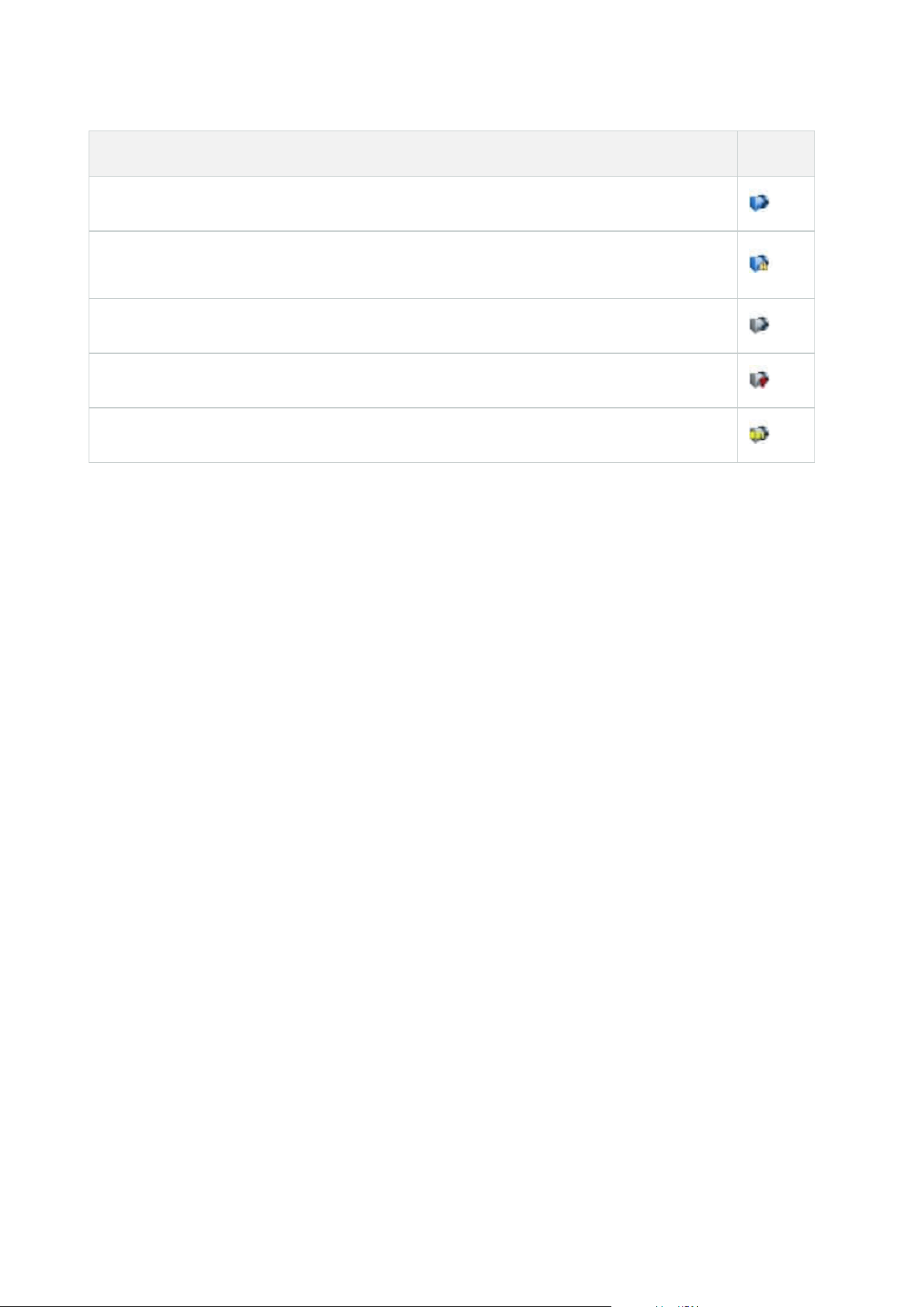
Description Icon
The top site in the entire hierarchy is operational.
The top site in the entire hierarchy is still operational, but one or more issues need attention.
Shown on top of the top site icon.
The site is operational.
The site is awaiting to be accepted in the hierarchy.
The site is attaching but is not yet operational.
Ports used by the system
All XProtect components and the ports needed by them are listed below. To ensure, for example, that the
firewall blocks only unwanted traffic, you need to specify the ports that the system uses. You should only
enable these ports. The lists also include the ports used for local processes.
They are arranged in two groups:
l
Server components (services) offer their service on particular ports which is why they need to listen for
client requests on these ports. Therefore, these ports need to be opened in the Windows Firewall for
inbound and outbound connections
l
Client components (clients) initiate connections to particular ports on server components. Therefore,
these ports need to be opened for outbound connections. Outbound connections are typically open by
default in the Windows Firewall
If nothing else is mentioned, ports for server components must be opened for inbound connections, and ports
for client components must be opened for outbound connections.
Do keep in mind that server components can act as clients to other server components. These are not explicitly
listed in this doc.
The port numbers are the default numbers, but this can be changed. Contact Milestone support, if you need to
change ports that are not configurable through the Management Client.
Server components (inbound connections)
Each of the following sections list the ports that need to be opened for a particular service. To figure out which
ports need to be opened on a particular computer, you need to consider all services running on the computer.
Management Server service and related processes
Administrator manual | XProtect® VMS 2023 R1
91 | Overview

Port
number
Protocol Process
Connections
from...
Purpose
80 HTTP IIS
All servers and
the XProtect
Smart Client and
the
Management
Client
The purpose of port 80 and port
443 is the same. However, which
port the VMS uses depends on
whether you have used
certificates to secure the
communication.
l
When you have not
secured the
communication with
certificates, the VMS uses
port 80.
l
When you have secured
the communication with
certificates, the VMS uses
port 443 except for
communication from the
event server to the
management server. The
communication from the
event server to the
management server uses
Windows Secured
Framework (WCF) and
Windows authentication
on port 80.
443 HTTPS IIS
6473 TCP
Management
Server service
Management
Server Manager
tray icon, local
connection only.
Showing status and managing
the service.
8080 TCP
Management
server
Local connection
only.
Communication between internal
processes on the server.
9000 HTTP
Management
server
Recording
Server services
Web service for internal
communication between servers.
Administrator manual | XProtect® VMS 2023 R1
92 | Overview

Port
number
Protocol Process
Connections
from...
Purpose
12345 TCP
Management
Server service
XProtect Smart
Client
Communication between the
system and Matrix recipients.
You can change the port number
in the Management Client.
12974 TCP
Management
Server service
Windows SNMP
Service
Communication with the SNMP
extension agent.
Do not use the port for other
purposes even if your system
does not apply SNMP.
In XProtect 2014 systems or
older, the port number was 6475.
In XProtect 2019 R2 systems and
older, the port number was 7475.
SQL Server service
Port
number
Protocol Process
Connections
from...
Purpose
1433 TCP SQL Server
Management
Server service
Storing and retrieving configurations
via the Identity Provider.
1433 TCP SQL Server
Event Server
service
Storing and retrieving events via the
Identity Provider.
1433 TCP SQL Server
Log Server
service
Storing and retrieving log entries via
the Identity Provider.
Data Collector service
Administrator manual | XProtect® VMS 2023 R1
93 | Overview

Port
number
Protocol Process Connections from... Purpose
7609 HTTP IIS
On the management server computer: Data
Collector services on all other servers.
On other computers: Data Collector service
on the Management Server.
System
Monitor.
Event Server service
Port
number
Protocol Process Connections from... Purpose
1234 TCP/UDP
Event
Server
Service
Any server sending generic
events to your XProtect
system.
Listening for generic
events from external
systems or devices.
Only if the relevant data
source is enabled.
1235 TCP
Event
Server
service
Any server sending generic
events to your XProtect
system.
Listening for generic
events from external
systems or devices.
Only if the relevant data
source is enabled.
9090 TCP
Event
Server
service
Any system or device that
sends analytics events to your
XProtect system.
Listening for analytics
events from external
systems or devices.
Only relevant if the
Analytics Events feature is
enabled.
22331 TCP
Event
Server
service
XProtect Smart Client and the
Management Client
Configuration, events,
alarms, and map data.
Administrator manual | XProtect® VMS 2023 R1
94 | Overview

Port
number
Protocol Process Connections from... Purpose
22332 WS/WSS
Event
Server
service
API Gateway Reserved for future use.
22333 TCP
Event
Server
service
MIP Plug-ins and applications. MIP messaging.
Recording Server service
Port
number
Protocol Process
Connections
from...
Purpose
25 SMTP
Recording
Server
Service
Cameras,
encoders, and
I/O devices.
Listening for event messages from
devices.
The port is disabled by default.
(Deprecated) Enabling this will open
a port for non-encrypted
connections and is not
recommended.
5210 TCP
Recording
Server
Service
Failover
recording
servers.
Merging of databases after a
failover recording server had been
running.
5432 TCP
Recording
Server
Service
Cameras,
encoders, and
I/O devices.
Listening for event messages from
devices.
The port is disabled by default.
7563 TCP
Recording
Server
Service
XProtect Smart
Client,
Management
Client
Retrieving video and audio streams,
PTZ commands.
Administrator manual | XProtect® VMS 2023 R1
95 | Overview

Port
number
Protocol Process
Connections
from...
Purpose
8966 TCP
Recording
Server
Service
Recording
Server Manager
tray icon, local
connection only.
Showing status and managing the
service.
9001 HTTP
Recording
Server
Service
Management
server
Web service for internal
communication between servers.
If multiple Recording Server
instances are in use, every instance
needs its own port. Additional ports
will be 9002, 9003, etc.
11000 TCP
Recording
Server
Service
Failover
recording
servers
Polling the state of recording
servers.
12975 TCP
Recording
Server
Service
Windows SNMP
service
Communication with the SNMP
extension agent.
Do not use the port for other
purposes even if your system does
not apply SNMP.
In XProtect 2014 systems or older,
the port number was 6474.
In XProtect 2019 R2 systems and
older, the port number was 7474.
65101 UDP
Recording
Server
service
Local connection
only
Listening for event notifications
from the drivers.
Administrator manual | XProtect® VMS 2023 R1
96 | Overview

In addition to the inbound connections to the Recording Server service listed above, the
Recording Server service establishes outbound connections to:
l
Cameras
l
NVRs
l
Remote interconnected sites (Milestone Interconnect ICP)
Failover Server service and Failover Recording Server service
Port
number
Protocol Process Connections from... Purpose
25 SMTP
Failover
Recording
Server
Service
Cameras, encoders,
and I/O devices.
Listening for event messages
from devices.
The port is disabled by default.
(Deprecated) Enabling this will
open a port for non-encrypted
connections and is not
recommended.
5210 TCP
Failover
Recording
Server
Service
Failover recording
servers
Merging of databases after a
failover recording server had
been running.
5432 TCP
Failover
Recording
Server
Service
Cameras, encoders,
and I/O devices.
Listening for event messages
from devices.
The port is disabled by default.
7474 TCP
Failover
Recording
Server
Service
Windows SNMP
service
Communication with the SNMP
extension agent.
Do not use the port for other
purposes even if your system
does not apply SNMP.
7563 TCP
Failover
XProtect Smart Client
Retrieving video and audio
Administrator manual | XProtect® VMS 2023 R1
97 | Overview

Port
number
Protocol Process Connections from... Purpose
Recording
Server
Service
streams, PTZ commands.
8844 UDP
Failover
Recording
Server
Service
Communication
between failover
recording server
services.
Communication between the
servers.
8966 TCP
Failover
Recording
Server
Service
Failover Recording
Server Manager tray
icon, local connection
only.
Showing status and managing
the service.
8967 TCP
Failover
Server
Service
Failover Server
Manager tray icon,
local connection only.
Showing status and managing
the service.
8990 TCP
Failover
Server
Service
Management Server
service
Monitoring the status of the
Failover Server service.
9001 HTTP
Failover
Server
Service
Management server
Web service for internal
communication between
servers.
In addition to the inbound connections to the Failover Server / Failover Recording Server
service listed above, the Failover Server / Failover Recording Server service establishes
outbound connections to the regular recorders, cameras, and for Video Push.
Log Server service
Administrator manual | XProtect® VMS 2023 R1
98 | Overview

Port
number
Protocol Process Connections from... Purpose
22337 HTTP
Log Server
service
All XProtect components except for
Management Client and the
recording server.
Write to, read from,
and configure the
log server.
Mobile Server service
Port
number
Protocol Process Connections from... Purpose
8000 TCP
Mobile
Server
service
Mobile Server Manager tray
icon, local connection only.
SysTray application.
8081 HTTP
Mobile
Server
service
Mobile clients, Web clients, and
Management Client.
Sending data streams;
video and audio.
8082 HTTPS
Mobile
Server
service
Mobile clients and Web clients.
Sending data streams;
video and audio.
40001 -
40099
HTTP
Mobile
Server
service
Recording server service
Mobile Server Video
Push.
This port range is
disabled by default.
LPR Server service
Administrator manual | XProtect® VMS 2023 R1
99 | Overview

Port
number
Protocol Process Connections from... Purpose
22334 TCP
LPR Server
Service
Event server
Retrieving recognized license
plates and server status.
In order to connect, the Event
server must have the LPR plug-
in installed.
22334 TCP
LPR Server
Service
LPR Server Manager
tray icon, local
connection only.
SysTray application
Milestone Open Network Bridge service
Port
number
Protocol Process
Connections
from...
Purpose
580 TCP
Milestone Open
Network Bridge
Service
ONVIF clients
Authentication and requests
for video stream
configuration.
554 RTSP RTSP Service ONVIF clients
Streaming of requested video
to ONVIF clients.
XProtect DLNA Server service
Port
number
Protocol Process
Connections
from...
Purpose
9100 HTTP
DLNA
Server
Service
DLNA device
Device discovery and providing DLNA
channels configuration. Requests for
video streams.
Administrator manual | XProtect® VMS 2023 R1
100 | Overview

Port
number
Protocol Process
Connections
from...
Purpose
9200 HTTP
DLNA
Server
Service
DLNA device
Streaming of requested video to DLNA
devices.
XProtect Screen Recorder service
Port
number
Protocol Process
Connections
from...
Purpose
52111 TCP
XProtect
Screen
Recorder
Recording
Server Service
Provides video from a monitor. It
appears and acts in the same way as a
camera on the recording server.
You can change the port number in
the Management Client.
XProtect Incident Manager service
Port
number
Protocol Process
Connections
from...
Purpose
80 HTTP IIS
XProtect Smart
Client and the
Management
Client
The purpose of port 80 and port 443 is
the same. However, which port the
VMS uses depends on whether you
have used certificates to secure the
communication.
l
When you have not secured the
communication with certificates,
the VMS uses port 80.
l
When you have secured the
communication with certificates,
the VMS uses port 443.
443 HTTPS IIS
Administrator manual | XProtect® VMS 2023 R1
101 | Overview

Server components (outbound connections)
Management Server service
Port
number
Protocol Connections to... Purpose
443 HTTPS
The License server that hosts the
License Management service.
Communication is via
https://www.milestonesys.com/
OnlineActivation/
LicenseManagementService.asmx
Activating
licenses.
Recording Server service
Port
number
Protocol Connections to... Purpose
80 HTTP
Cameras, NVRs,
encoders
Interconnected sites
Authentication, configuration, data streams, video,
and audio.
Login
443 HTTPS
Cameras, NVRs,
encoders
Authentication, configuration, data streams, video,
and audio.
554 RTSP
Cameras, NVRs,
encoders
Data streams, video, and audio.
7563 TCP Interconnected sites Data streams and events.
11000 TCP
Failover recording
servers
Polling the state of recording servers.
40001 –
40099
HTTP
Mobile Server
service
Mobile Server Video Push.
This port range is disabled by default.
Failover Server service and Failover Recording Server service
Administrator manual | XProtect® VMS 2023 R1
102 | Overview

Port number Protocol Connections to... Purpose
11000 TCP Failover recording servers Polling the state of recording servers.
Event Server service
Port
number
Protocol Connections to... Purpose
443 HTTPS
Milestone Customer Dashboard via
https://service.milestonesys.com/
Send status, events and error
messages from the XProtect
system to Milestone Customer
Dashboard.
Log Server service
Port number Protocol Connections to... Purpose
443 HTTP Log server Forwarding messages to the log server.
API Gateway
Port number Protocol Connections to... Purpose
443 HTTPS
Management
sever
RESTful API
Cameras, encoders, and I/O devices (inbound connections)
Administrator manual | XProtect® VMS 2023 R1
103 | Overview

Port
number
Protocol Connections from... Purpose
80 TCP
Recording servers and failover
recording servers
Authentication, configuration, and data
streams; video and audio.
443 HTTPS
Recording servers and failover
recording servers
Authentication, configuration, and data
streams; video and audio.
554 RTSP
Recording servers and failover
recording servers
Data streams; video and audio.
Cameras, encoders, and I/O devices (outbound connections)
Port
number
Protocol Connections to... Purpose
25 SMTP
Recording servers and failover
recording servers
Sending event
notifications (deprecated).
5432 TCP
Recording servers and failover
recording servers
Sending event
notifications.
The port is disabled by
default.
22337 HTTP Log server
Forwarding messages to
the log server.
Only a few camera models are able to establish outbound connections.
Client components (outbound connections)
XProtect Smart Client, XProtect Management Client, XProtect Mobile server
Administrator manual | XProtect® VMS 2023 R1
104 | Overview

Port
number
Protocol Connections to... Purpose
80 HTTP
Management Server
service
Authentication
443 HTTPS
Management Server
service
Authentication of basic users when
encryption is enabled.
443 HTTPS
Milestone Systems A/S
(doc.milestonesys.com at
52.178.114.226)
Management Client and Smart Client
occasionally check if the online help is
available by accessing the help URL.
7563 TCP Recording Server service
Retrieving video and audio streams, PTZ
commands.
22331 TCP Event Server service Alarms.
XProtect Web Client, XProtect Mobile client
Port number Protocol Connections to... Purpose
8081 HTTP XProtect Mobile server Retrieving video and audio streams.
8082 HTTPS XProtect Mobile server Retrieving video and audio streams.
API Gateway
Port number Protocol Connections to... Purpose
80 HTTP Management Server RESTful API
443 HTTPS Management Server RESTful API
Administrator manual | XProtect® VMS 2023 R1
105 | Overview

Application pools
The VMS contains standard application pools such as.NET v4.5, .NET v4.5 Classic and the DefaultAppPool. The
application pools that are available on your system appear in the Internet Information Services (IIS) Manager.
In addition to the standard application pools mentioned above, a set of VideoOS application pools are
delivered with the Milestone XProtect VMS.
Application pools in Milestone XProtect
In the table below you can get an overview of the VideoOS application pools that are delivered with Milestone
XProtect.
Name Identity Purpose
.NET v4.5 ApplicationPoolId Standard IIS feature
.NET v4.5 Classic ApplicationPoolId Standard IIS feature
DefaultAppPool ApplicationPoolId Standard IIS feature
VideoOS ApiGateway NetworkService
Hosts the XProtect API Gateway which
is the future public API and gateway
to the VMS.
VideoOS Classic NetworkService
Hosts legacy components such as the
local help mainly to comply with
backwards compatibility.
VideoOS IDP NetworkService
Hosts the Identity Provider API. The
Identity Provider creates, maintains,
and manages identity information for
basic users and provides
authentication and registration
services to relying applications or
services.
VideoOS IM NetworkService
Hosts the XProtect Incident Manager
API. The XProtect Incident Manager
documents incidents and combine
them with sequence evidence (video
and, potentially, audio) from their
XProtect VMS.
Administrator manual | XProtect® VMS 2023 R1
106 | Overview

Working with application pools
From the Application Pools page in the Internet Information Services (IIS) window you can add application
pools or set appplication pool defaults and you can view the applications hosted by each application pool.
Open the Application Pools page
1. From the Windows Start menu, open Internet Information Servces (IIS) Manager.
2. In the Connections pane, click the name of your environment, and then click Application Pools.
3. Under Actions, click Add Application Pool or Set Application Pool Defaults to perform any of these
tasks.
4. Select an application pool on the Application Pools page to display further options under Actions for
each application pool.
Product comparison
XProtect VMS includes the following products:
l
XProtect Corporate
l
XProtect Expert
l
XProtect Professional+
l
XProtect Express+
l
XProtect Essential+
See the complete feature list, which is available on the product overview page on the Milestone website
(https://www.milestonesys.com/solutions/platform/product-index/).
Administrator manual | XProtect® VMS 2023 R1
107 | Overview

Licensing
Licenses (explained)
Free XProtect Essential+
If you have installed XProtect Essential+, you can run the system and eight device licenses for free. Automatic
license activation is enabled, and hardware will be activated as you add it to the system.
Only when you upgrade to a more advanced XProtect product and need to change your SLC (Software License
Code) (see Change the Software License Code on page 117), the rest of this topic and the other licensing-
related topics in this documentation could be relevant for you.
Licenses for XProtect VMS products (except XProtect Essential+)
Software license file and SLCs
When you purchase your software and licenses, you get:
l
An order confirmation and a software license file named after your SLC (Software License Code) and
with the .lic extension received per email
l
A Milestone Care coverage
Your SLC is also printed on your order confirmation and consists of several numbers and letters grouped by
hyphens like:
l
Product version 2014 or earlier: xxx-xxxx-xxxx
l
Product version 2016 or later: xxx-xxx-xxx-xx-xxxxxx
The software license file contains all information about your purchased VMS products, add-on products, and
licenses. Milestone recommends that you store the information about your SLC and a copy of your software
license file in a safe place for later use. You can also see your SLC in the License Information window in
Management Client. You can open the License Information window in the Site Navigation pane -> Basics
node -> License Information. You may need the software license file or your SLC when you, for example,
create a My Milestone user account, contact your reseller for support, or if you need to make changes to your
system.
Overall process for installation and licensing
To get started, you download the software from our website (https://www.milestonesys.com/downloads/).
While you are installing (see Install a new XProtect system on page 140) the software, you are asked to provide
the software license file. You cannot complete the installation without a software license file.
Administrator manual | XProtect® VMS 2023 R1
108 | Licensing

Once the installation is complete and you have added some cameras, you must activate your licenses (see
License activation (explained) on page 110. You activate your licenses from the License Information window in
Management Client. Here you can also see an overview of your licenses for all installations on the same SLC.
You can open the License Information window in the Site Navigation pane -> Basics node -> License
Information.
License types
There are several license types in the XProtect licensing system.
Base licenses
As a minimum, you have a base license for one of the XProtect VMS products. You may also have one or more
base licenses for XProtect add-on products.
Device licenses
As a minimum, you have several device licenses. Generally, you need one device license per hardware device
with a camera that you want to add to your system. But this can differ from one hardware device to another
and depending on the hardware device being a Milestone supported hardware device or not. For more
information, see Supported hardware devices on page 109 and Unsupported hardware devices on page 109.
If you want to use the video push feature in XProtect Mobile, you also need one device license per mobile
device or tablet that should be able to push video to your system.
Device licenses are not required for speakers, microphones, or input and output devices attached to your
cameras.
Supported hardware devices
Generally, you need one device license per hardware device with a camera that you want to add to your
system. But a few supported hardware devices require more than one device license. You can see how many
device licenses your hardware devices require, in the list of supported hardware on the Milestone website
(https://www.milestonesys.com/support/tools-and-references/supported-devices/).
For video encoders with up to 16 channels, you need only one device license per video encoder IP address. A
video encoder can have one or more IP addresses.
However, if the video encoder has more than 16 channels, one device license per activated camera on the
video encoder is required - also for the first 16 activated cameras.
Unsupported hardware devices
An unsupported hardware device requires one device license per activated camera using a video channel.
Unsupported hardware devices do not appear in the list of supported hardware on the Milestone website
(https://www.milestonesys.com/support/tools-and-references/supported-devices/).
Administrator manual | XProtect® VMS 2023 R1
109 | Licensing

Camera licenses for Milestone Interconnect™
To run Milestone Interconnect, you need Milestone Interconnect camera licenses on your central site to view
video from hardware devices on remote sites. The number of required Milestone Interconnect camera licenses
depends on the number of hardware devices on the remote sites that you want to receive data from. Only
XProtect Corporate can act as a central site.
Licenses for add-on products
Most XProtect add-on products require additional license types. The software license file also includes
information about your licenses for add-on products. Some add-on products have their own separate software
license files.
License activation (explained)
Your SLC must be registered prior to the installation (see Register Software License Code on page 137). Your
different licenses connected with your SLCs must be activated for the installed XProtect VMS and add-on
products to work and the individual hardware devices to be able to send data to the system. For an overview of
all XProtect license types, see License types on page 109.
There are several ways of activating licenses. All of them are available from the License Information window.
The best way of activating depends on your organization's policies and whether your management server has
access to the internet or not. To learn how to activate licenses, see Activate your licenses on page 115.
After the initial license activation of your XProtect VMS, you do not have to activate device licenses every time
you add a hardware device with a camera because of built-in flexibilities to the XProtect licensing system. For
more information about these flexibilities, see Grace period for license activation (explained) on page 111 and
Device changes without activation (explained) on page 111.
Automatic license activation (explained)
For easy maintenance and flexibility - and when your organization's policies permit it - Milestone recommends
that you enable automatic license activation. Automatic license activation requires that the management
server is online. For how to enable automatic license activation, see Enable automatic license activation on
page 115.
Benefits of enabling automatic license activation
l
The system activates your hardware devices a few minutes after you have added, removed, or replaced
hardware devices or made other changes that affect the use of your licenses. Therefore, you only
seldom must manually start a license activation. See the few exceptions in When manual license
activation is still required on page 111.
l
The used number of device changes without activation is always zero.
Administrator manual | XProtect® VMS 2023 R1
110 | Licensing

l
No hardware devices are within a grace period and at risk of expiring.
l
If one of your base licenses expires within a period of 14 days, your XProtect system will also - as an
extra precaution - automatically try to activate your licenses every night.
When manual license activation is still required
If you make the following changes to your system, manual license activation is required.
l
Purchase additional licenses (see Get additional licenses on page 117)
l
Upgrade to a newer version or more advanced VMS system (see Upgrade requirements on page 355)
l
Buy or renew a Milestone Care subscription
l
Receive allowance for more device changes without activation (see Device changes without activation
(explained) on page 111)
Grace period for license activation (explained)
When you have installed your VMS and added devices (hardware devices, Milestone Interconnect cameras, or
door licenses), the devices run in a 30-day grace period if you have decided not to enable automatic license
activation. Before the end of the 30-day grace period and if you do not have more device changes without
activation left, you must activate your licenses, or your devices will stop sending video to your surveillance
system.
Device changes without activation (explained)
The functionality device changes without activation gives built-in flexibility to the XProtect licensing system. So
even if you have decided to activate licenses manually, you do not necessarily have to activate licenses every
time you add or remove hardware devices.
The number of device changes without activation differs from installation to installation and is calculated
based on several variables. For a detailed description, see Calculation of available number of device changes
without activation (explained) on page 112.
One year after your last license activation, your used number of device changes without activation is
automatically reset to zero. Once the reset happens, you can continue to add and replace hardware devices
without activating the licenses.
If your surveillance system is offline for longer periods of time, for example in cases with a surveillance system
on a ship on a long cruise or a surveillance system in a very remote place without any Internet access, you can
contact your Milestone reseller and request a higher number of device changes without activation.
You must explain why you think you qualify for a higher number of device changes without activation.
Milestone decides each request on an individual basis. Should you be granted a higher number of device
changes without activation, you must activate your licenses to register the higher number on your XProtect
system.
Administrator manual | XProtect® VMS 2023 R1
111 | Licensing

Calculation of available number of device changes without activation
(explained)
The available number of device changes without activation is calculated based on three variables. If you have
several installations of the Milestone software, the variables apply to each of them separately. The variables are:
l
C% that is a fixed percentage of the total amount of activated licenses
l
Cmin that is a fixed minimum value of the number of device changes without activation
l
Cmax that is a fixed maximum value of the number of devices changes without activation
The number of device changes without activation can never be lower than the Cmin value or higher than the
Cmax value. The calculated value based on the C% variable changes according to how many activated devices
you have on each installation in your system. Devices added with device changes without activation are not
counted as activated by the C% variable.
Milestone defines the values of all three variables and the values are subject to change without notification.
The values of the variables differ depending on the product.
Examples based on C% = 15%, Cmin = 10 and Cmax =100
You buy 100 device licenses. You then add 100 cameras to the system. Unless you have enabled automatic
license activation, the number of device changes without activation is still zero. You activate your licenses and
have now 15 device changes without activation.
You buy 100 device licenses. You then add 100 cameras to the system and activate the licenses. Your number
of device changes without activation is now 15. You then decide to delete a hardware device from the system.
You now have 99 activated devices and the number of device changes without activation has dropped to 14.
You buy 1000 device licenses. You then add 1000 cameras and activates the licenses. Your device changes
without activation are now 100. According to the C% variable, you should now have had 150 device changes
without activation, but the Cmax variable only allows you to have 100 device changes without activation.
You buy 10 device licenses. You then add 10 cameras to the system and activates the licenses. Your number of
device changes without activation is now 10 because of the Cmin variable. If the number was only calculated
based on the C% variable, you would only have had 1 (15% of 10 = 1.5 rounded off to 1).
You buy 115 device licenses. You then add 100 cameras to the system and activate the licenses. Your device
changes without activation is now 15. You add another 15 cameras without activating them, using 15 out of 15
of your device changes without activation. You now remove 50 of the cameras from the system and the
number of device changes without activation goes down to 7. This means that 8 of the cameras previously
added within the 15 device changes without activation go into a grace period. You now add 50 new cameras.
Because you activated 100 cameras on the system last time you activated the licenses, the number of device
changes without activation goes back to 15 and the 8 cameras, that were moved into a grace period, move
back as device changes without activation. The 50 new cameras go into a grace period.
Administrator manual | XProtect® VMS 2023 R1
112 | Licensing

Milestone Care™ (explained)
Milestone Care is the name of the complete service and support program for XProtect products throughout
their lifetime.
Milestone Care gives you access to different types of self-help material like knowledge base articles, guides,
and tutorials on our Support website (https://www.milestonesys.com/support/).
For additional benefits, you can purchase more advance Milestone Care subscriptions.
Milestone Care Plus
If you have a Milestone Care Plus subscription, you also have access to free updates to your current XProtect
VMS product and can upgrade to more advanced XProtect VMS products at an advantageous price. Milestone
Care Plus also offers additional functionality:
l
The Customer Dashboard service
l
The Smart Connect feature
l
The full Push Notification functionality
Milestone Care Premium
If you have a Milestone Care Premium subscription, you can also contact the Milestone support team directly.
Please remember to include information about your Milestone Care ID when contacting Milestone support.
Expiration, renewal, and purchase of advanced Milestone Care subscriptions
The expiration date of the more advanced Milestone Care Plus and Milestone Care Premium subscription types is
visible in the License Information window in the Installed Products table. See Installed Products on page 119.
If you decide to buy or renew a Milestone Care subscription after you have installed your system, you must
manually activate your licenses before the correct Milestone Care information appears. See Activate licenses
online on page 116 or Activate licenses offline on page 116.
Licenses and hardware replacement (explained)
If a camera in the system gets faulty or you for other reasons want to replace the camera with a new one,
there are some best practices of how it should be done.
If you remove a camera from a recording server, you free a device license, but you also lose full access to all
databases (cameras, microphones, inputs, outputs) and the settings of the old camera. To keep access to the
databases of the old camera and reuse its settings when replacing it with a new camera, use the relevant
option below.
Administrator manual | XProtect® VMS 2023 R1
113 | Licensing

Replace camera with a similar camera
If you replace a camera with a similar camera (manufacturer, brand, and model), and if you give the new
camera the same IP address as the old one, you maintain full access to all databases of the old camera. The
new camera continues to use the same databases and settings as the old camera. In this case, you move the
network cable from the old camera to the new one without changing any settings in Management Client.
Replace camera with a different camera
If you replace a camera with a different camera (manufacturer, brand, and model), you must use the Replace
Hardware wizard (see Replace hardware on page 327) to map all relevant databases of the old camera to the
new one and reuse the settings of the old camera.
License activation after hardware replacement
If you have enabled automatic license activation (see Enable automatic license activation on page 115), the new
camera is automatically activated.
If automatic license activation is disabled, and if all of the available device changes without activation have
been used (see Device changes without activation (explained) on page 111), you must manually activate your
licenses. For more information about manually activating licenses, see Activate licenses online on page 116 or
Activate licenses offline on page 116.
Get an overview of your licenses
There are many reasons why you would like to get an overview of your SLCs and your number of purchased
licenses and their statuses. Here are a few:
l
You want to add one or more new hardware devices, but do you have unused device licenses, or do you
have to purchase new ones?
l
Is the grace period for some of your hardware devices ending soon? Then you must activate them
before they stop sending data to the VMS.
l
You know from previous contacts to support that they need information about your SLC and your
Milestone Care ID to be able to help you. But which are they?
l
You have many installations of XProtect and use the same SLC for all installations, but where are the
licenses used and what are their statuses?
You can find all the information above and more in the License Information window.
You can open the License Information window in the Site Navigation pane -> Basics node -> License
Information.
To learn more about the various information and features available from the License Information window, see
License Information window on page 118.
Administrator manual | XProtect® VMS 2023 R1
114 | Licensing

Activate your licenses
There are several ways of activating licenses. All of them are available from the License Information window.
The best way of activating depends on your organization's policies and whether your management server has
access to the internet or not.
You can open the License Information window in the Site Navigation pane -> Basics node -> License
Information.
To learn more about the various information and features available from the License Information window, see
License Information window on page 118.
Enable automatic license activation
For easy maintenance and flexibility - and when your organization's policies permit it - Milestone recommends
that you enable automatic license activation. Automatic license activation requires that the management
server is online.
If you want to know all the benefits of enabling automatic license activation, see Automatic license activation
(explained) on page 110.
1. From the Site Navigation pane -> Basics node -> License Information, select Enable automatic license
activation.
2. Enter the user name and password that you want to use with automatic license activation:
l
If you are an existing user, enter your user name and password to log into the software
registration system
l
If you are a new user, click the Create new user link to set up a new user account and then
follow the registration procedure. If you have not yet registered your Software License Code
(SLC), you must do so
The credentials are saved in a file on the management server.
3. Click OK.
If you later want to change your user name and/or the password for automatic activation, click the Edit
activation credentials link.
Disable automatic license activation
If it is not allowed to use automatic license activation in your organization or simply you have changed your
mind, you can disable automatic license activation.
How you disable depends on whether you later plan to use automatic license activation again or not.
Administrator manual | XProtect® VMS 2023 R1
115 | Licensing

Disable but keep the password for later use:
1. From the Site Navigation pane -> Basics node -> License Information, clear Enable automatic license
activation. The user name and password are still saved on the management server.
Disable and delete password:
1. From the Site Navigation pane -> Basics node -> License Information, click Edit activation
credentials.
2. Click Delete password.
3. Confirm that you want to delete the user name and password from the management server.
Activate licenses online
If the management server has internet access but you prefer to manually start the activation process, this is
the easiest license activation option for you.
1. From the Site Navigation pane -> Basics node -> License Information, select Activate License
Manually and then Online.
2. The Activate Online dialog box opens:
l
If you are an existing user, enter your user name and password
l
If you are a new user, click the Create new user link to set up a new user account. If you have
not yet registered your Software License Code (SLC), you must do so
3. Click OK.
If you receive an error message during online activation, follow the instructions on the screen to solve the
issue or contact Milestone support.
Activate licenses offline
If your organization does not allow that the management server has internet access, you must activate
licenses manually and offline.
1. From the Site Navigation pane -> Basics node -> License Information, select Activate License
Manually > Offline > Export License for Activation to export a license request file (.lrq) with
information about your added hardware devices and other elements that require a license.
2. The license request file (.lrq) is automatically given the same name as your SLC. If you have several sites,
remember to rename the files so you can easily identify which file belongs to which site.
3. Copy the license request file to a computer with internet access and log into our website
(https://online.milestonesys.com/) to obtain the activated software license file (.lic).
4. Copy the .lic file you receive to your computer with Management Client. The file has been given the
same name as your license request file.
Administrator manual | XProtect® VMS 2023 R1
116 | Licensing

5. From the Site Navigation pane -> Basics node -> License Information, select Activate License Offline
> Import Activated License, and then select the activated software license file to import it and thereby
activate your licenses.
6. Click Finish to end the activation process.
Activate licenses after grace period
If you have decided to use manual license activation and you have forgotten to activate a license within the
grace period (hardware device, Milestone Interconnect camera, door licenses, or others), the device using that
license becomes unavailable and cannot send data to the surveillance system
Even if a license’s grace period has expired, the device configuration and settings you have made are saved
and used when the license is activated.
To enable the unavailable devices again, you activate the licenses manually in your preferred way. For more
information, see Activate licenses offline on page 116 or Activate licenses online on page 116.
Get additional licenses
If you want to add or if you have already added more hardware devices, Milestone Interconnect systems,
doors or other elements than you currently have licenses for, you must buy additional licenses to enable them
to send data to your system:
l
To get additional licenses for your system, contact your XProtect product reseller
If you have bought new licenses to your existing surveillance system version:
l
Simply activate your licenses manually to get access to the new licenses. For more information, see
Activate licenses online on page 116 or Activate licenses offline on page 116.
If you have bought new licenses and an upgraded surveillance system version:
l
You receive an updated software license file (.lic) (see Licenses (explained) on page 108) with the new
licenses and the new version. You must use the new software license file during the installation of the
new version. For more information, see Upgrade requirements on page 355
Change the Software License Code
If you run an installation on a temporary Software License Code (SLC) or if you have upgraded to a more
advanced XProtect product, you can change your SLC to a permanent or more advanced SLC. You can change
your SLC without any un- or reinstallation actions when you have received your new software license file.
You can do this locally on the management server or remotely from Management Client.
Administrator manual | XProtect® VMS 2023 R1
117 | Licensing
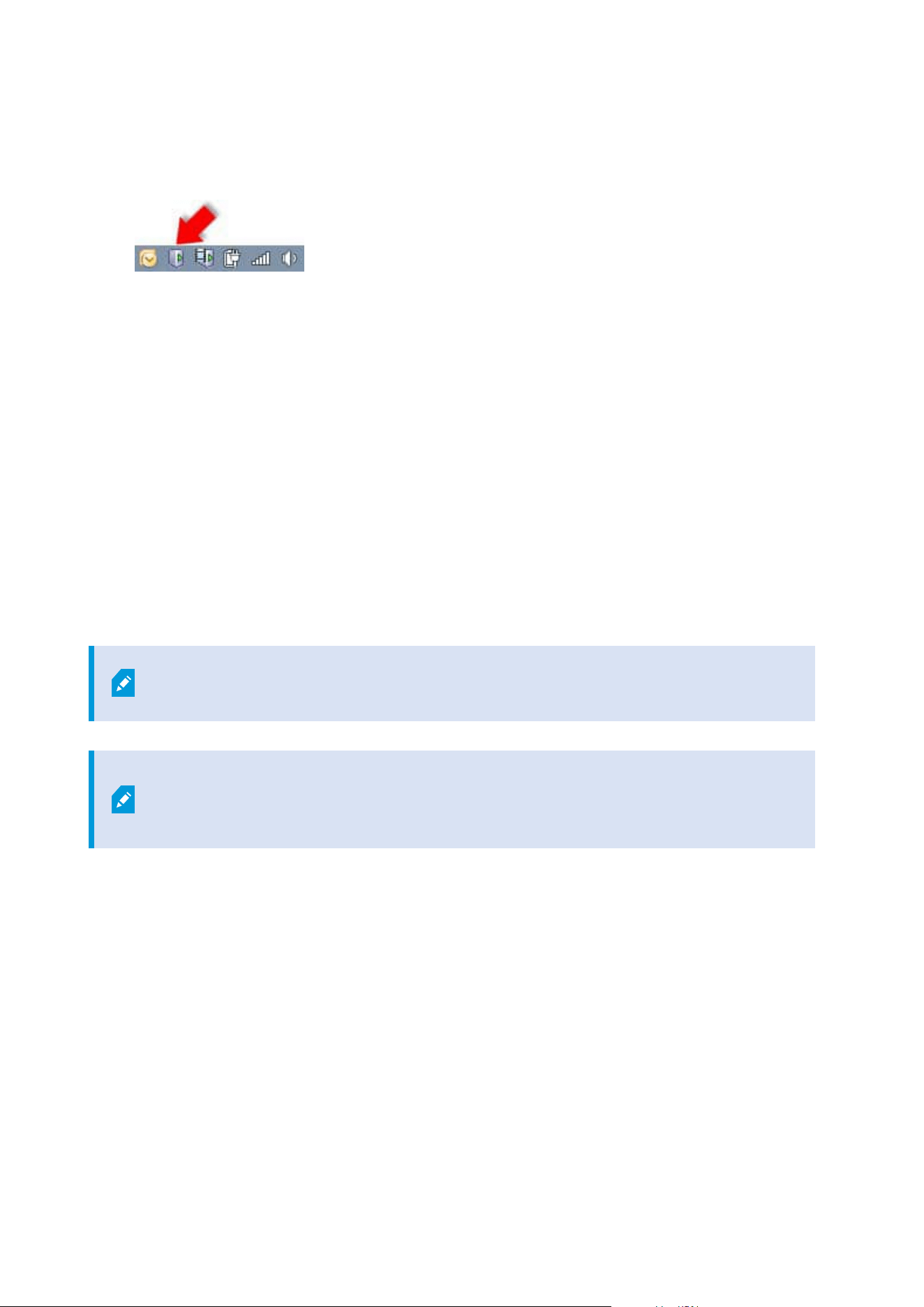
From the management server tray icon
1. On the management server, go to the notification area of the taskbar.
2. Right-click the Management Server icon and select Change License.
3. Click Import License.
4. Next, select the software license file saved for this purpose. When done, the selected software license
file location is added just below the Import License button.
5. Click OK and you are now ready to register SLC. See Register Software License Code on page 137.
From Management Client
1. Copy the .lic file you receive to your computer with Management Client.
2. From the Site Navigation pane -> Basics node -> License Information, select Activate License Offline
> Import Activated License, and then select the software license file to import.
3. When opened, accept that the software license file is different from the one currently in use.
4. You are now ready to register SLC. See Register Software License Code on page 137.
The software license file is only imported and changed but not activated. Remember to
activate your license. For more information, see Activate your licenses on page 115.
When running XProtect Essential+, you can only change the license from the
management server tray icon. It is not possible to change the license from Management
Client.
License Information window
In the License Information window, you can keep track of all licenses that share the same software license file
both on this site and on all other sites, your Milestone Care subscriptions and decide how you want to activate
your licenses.
You can open the License Information window in the Site Navigation pane -> Basics node -> License
Information.
If you want to have an overall understanding of how the XProtect licensing system works, see Licenses
(explained) on page 108.
Administrator manual | XProtect® VMS 2023 R1
118 | Licensing
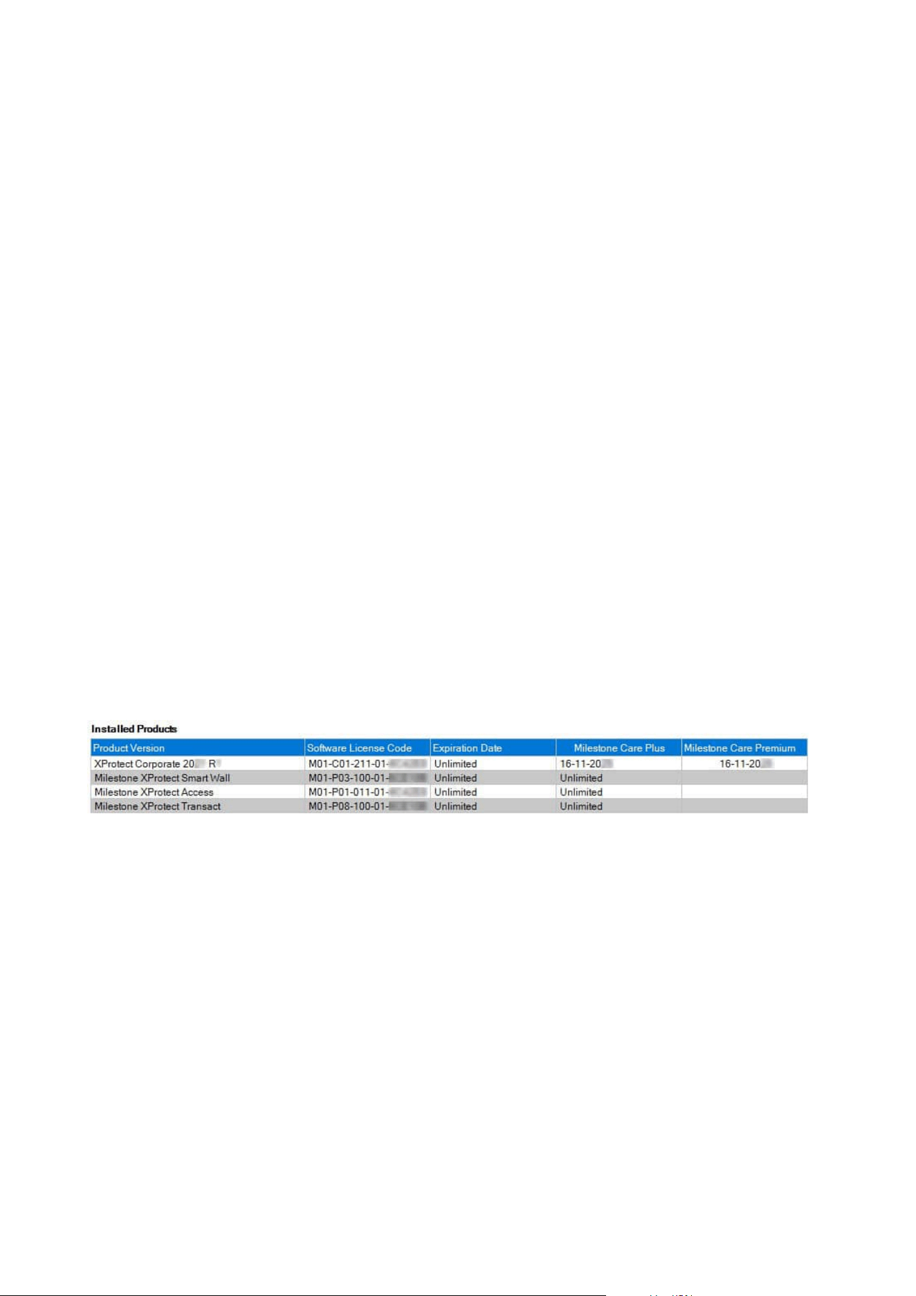
Licensed to
This area of the License Information window, lists the contact details of the license owner that was entered
during the software registration.
If you cannot see the Licensed to area, click the Refresh button in the lower right corner of the window.
Click Edit details to edit the license owner information. Click End-user license agreement to see the end-user
license agreement that you accepted prior to the installation.
Milestone Care
Here you can see information about your current Milestone Care™ subscription. The expiry dates for your
subscriptions are shown in the Installed Products table below.
For more information about Milestone Care, use the links or see Milestone Care™ (explained) on page 113.
Installed Products
Lists the following information about all your installed base licenses for XProtect VMS and add-on products
that share the same software license file:
l
Products and versions
l
The products' software license code (SLC)
l
The expiration date of your SLC. Typically, unrestricted
l
The expiration date of your Milestone Care Plus subscription
l
The expiration date of your Milestone Care Premium subscription
License Overview - All sites
Lists the number of activated device licenses and other licenses in your software license file and the total
number of available licenses on your system. Here you can easily see if you can still grow your system without
purchasing additional licenses.
For a detailed overview of the status of your licenses activated on other sites, click the License Details - All
sites link. See the License Details - Current site section below for the available information that is shown.
Administrator manual | XProtect® VMS 2023 R1
119 | Licensing
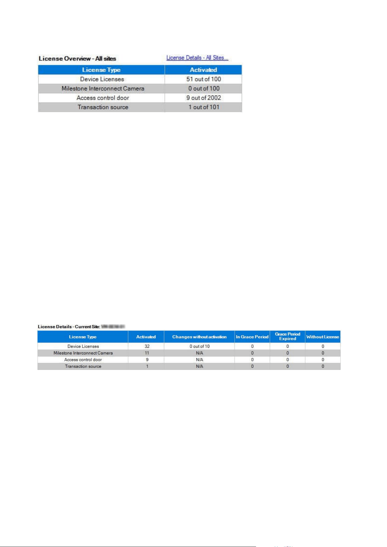
If you have licenses for add-on products, you can see additional details about these under the add-on product
specific nodes in the Site Navigation pane.
License Details - Current Site
The Activated column lists the number of activated device licenses or other licenses on this site.
You can also see the number of used device changes without activation (see Device changes without activation
(explained) on page 111) and how many you have available per year in the Changes without activation
column.
If you have licenses that you have not yet activated and that therefore run in a grace period, these are listed in
the In Grace Period column. The expiration date of the first license which expires, appears in red below the
table.
If you forget to activate licenses before the grace period expires, they will stop sending video to the system.
These licenses are shown in the Grace Period Expired column. For more information, see Activate licenses
after grace period on page 117.
If you have used more licenses than you have available, these are listed in the Without License column and
cannot be used in your system. For more information, see Get additional licenses on page 117.
If you have licenses in a grace period, with an expired grace period or without license, a message will remind
you every time you log into your Management Client.
If you have hardware devices that use more than one license, a Click here to open full device license report
link appears underneath the License Details - Current Site table. When you click the link, you can see how
many device licenses, each of these hardware devices require.
Hardware devices without licenses are identified by an exclamation mark in the Management Client. The
exclamation mark is also used for other purposes. Place your mouse over the exclamation mark to see the
purpose.
Features for activating licenses
Below the three tables are:
Administrator manual | XProtect® VMS 2023 R1
120 | Licensing
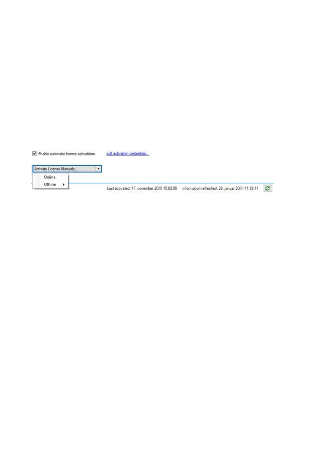
l
A check box for enabling automatic license activation and a link to edit the user credentials for
automatic activation. For more information, see Automatic license activation (explained) on page 110
and Enable automatic license activation on page 115.
If the automatic activation has failed, a failed message will appear in red. For more information, click
the Details link.
Some licenses, such as XProtect Essential+, are installed with the automatic license activation enabled,
and disabling it is not possible.
l
A drop-down list for manually activating licenses online or offline. For more information, see Activate
licenses online on page 116 and Activate licenses offline on page 116.
l
In the lower right corner of the window, you can see when your licenses were activated last
(automatically or manually) and when the information in the window were refreshed. The time stamps
are from the server and not from the local computer
Administrator manual | XProtect® VMS 2023 R1
121 | Licensing

Requirements and considerations
Daylight saving time (explained)
Daylight saving time (DST) is the practice of advancing clocks for evenings to have more daylight and mornings
to have less. The use of DST varies between countries/regions.
When you work with a surveillance system, which is inherently time-sensitive, it is important that you know
how the system handles DST.
Do not change the DST setting when you are in the DST period or if you have recordings
from a DST period.
Spring: Switch from Standard Time to DST
The change from standard time to DST is not much of an issue since you jump one hour forward.
Example:
The clock jumps forward from 02:00 standard time to 03:00 DST, and the day has 23 hours. In that case, there
is no data between 02:00 and 03:00 in the morning since that hour, for that day, did not exist.
Fall: Switch from DST to Standard Time
When you switch from DST to standard time in the fall, you jump one hour back.
Example:
The clock jumps backward from 02:00 DST to 01:00 standard time, repeating that hour, and the day has 25
hours. You reach 01:59:59, then immediately revert to 01:00:00. If the system did not react, it would essentially
re-record that hour, so the first instance of 01:30 would be overwritten by the second instance of 01:30.
To solve such an issue from happening, your system archives the current video in the event the system time
changes by more than five minutes. You cannot view the first instance of the 01:00 hour directly in any clients,
but the data is recorded and safe. You can browse this video in XProtect Smart Client by opening the archived
database directly.
Time servers (explained)
Once your system receives images, they are instantly time-stamped. Since cameras are separate units which
may have separate timing devices, camera time and your system time may not correspond fully. This may
occasionally lead to confusion. If your cameras support timestamps, Milestone recommends that you auto-
synchronize camera and system time through a time server for consistent synchronization.
For information about how to configure a time server, search the Microsoft website
(https://www.microsoft.com/) for 'time server', 'time service', or similar terms.
Administrator manual | XProtect® VMS 2023 R1
122 | Requirements and considerations
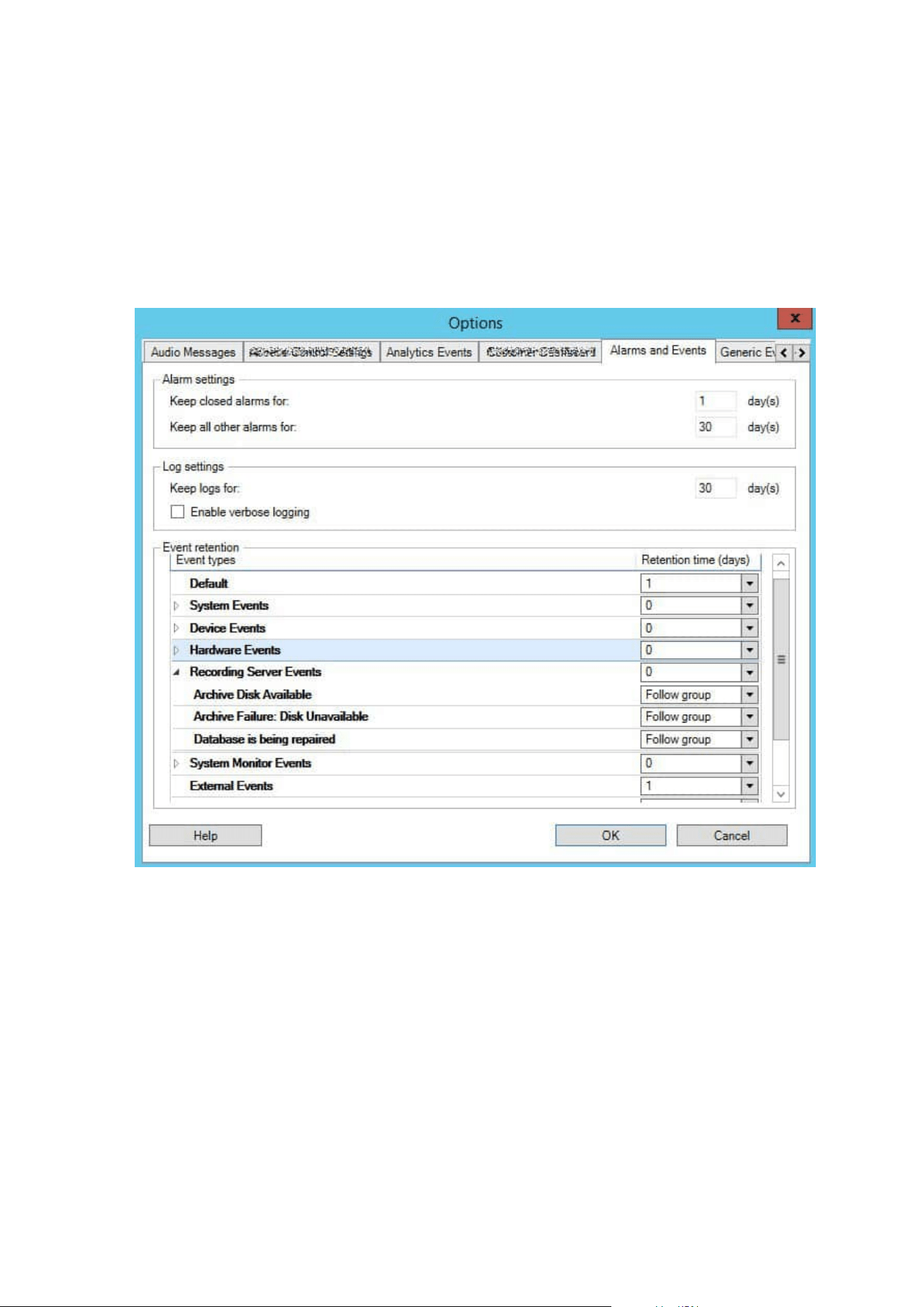
Limit size of database
To prevent the SQL database (see SQL Server installations and databases (explained) on page 32) growing to a
size that affects the performance of the system, you can specify for how many days the different types of
events and alarms are stored in the database.
1. Open the Tools menu.
2. ClickOptions>AlarmsandEventstab.
3. Make the required settings. For more information, see Alarms and Events tab (options) on page 379.
IPv6 and IPv4 (explained)
Your system supports IPv6 as well as IPv4. So does XProtect Smart Client.
IPv6 is the latest version of the Internet Protocol (IP). The Internet protocol determines the format and use of
IP addresses. IPv6 coexists with the still much more widely used IP version IPv4. IPv6 was developed in order
to solve the address exhaustion of IPv4. IPv6 addresses are 128-bit long, whereas IPv4 addresses are only 32-
bit long.
Administrator manual | XProtect® VMS 2023 R1
123 | Requirements and considerations

It meant that the Internet's address book grew from 4.3 billion unique addresses to 340 undecillion (340 trillion
trillion trillion) addresses. A growth factor of 79 octillion (billion billion billion).
More and more organizations are implementing IPv6 on their networks. For example, all US federal agency
infrastructures are required to be IPv6 compliant. Examples and illustrations in this manual reflect use of IPv4
because this is still the most widely used IP version. IPv6 works equally well with the system.
Using the system with IPv6 (explained)
The following conditions apply when using the system with IPv6:
Servers
Servers can often use IPv4 as well as IPv6. However, if just one server in your system (for example, a
management server or recording server) requires a particular IP version, all other servers in your system must
communicate using the same IP version.
Example: All of the servers in your system except one can use IPv4 as well as IPv6. The exception is a server
which is only capable of using IPv6. This means that all servers must communicate with each other using IPv6.
Devices
You can use devices (cameras, inputs, outputs, microphones, speakers) with a different IP version than that
being used for server communication provided your network equipment and the recording servers also
support the devices' IP version. See also the illustration below.
Clients
If your system uses IPv6, users should connect with the XProtect Smart Client. The XProtect Smart Client
supports IPv6 as well as IPv4.
If one or more servers in your system can only use IPv6, XProtect Smart Client users must use IPv6 for their
communication with those servers. In this context, it is important to remember that XProtect Smart Client
installations technically connect to a management server for initial authentication, and then to the required
recording servers for access to recordings.
However, the XProtect Smart Client users do not have to be on an IPv6 network themselves, provided your
network equipment supports communication between different IP versions, and they have installed the IPv6
protocol on their computers. See also illustration. To install IPv6 on a client computer, open a command
prompt, enter Ipv6 install, and press ENTER.
Example illustration
Administrator manual | XProtect® VMS 2023 R1
124 | Requirements and considerations
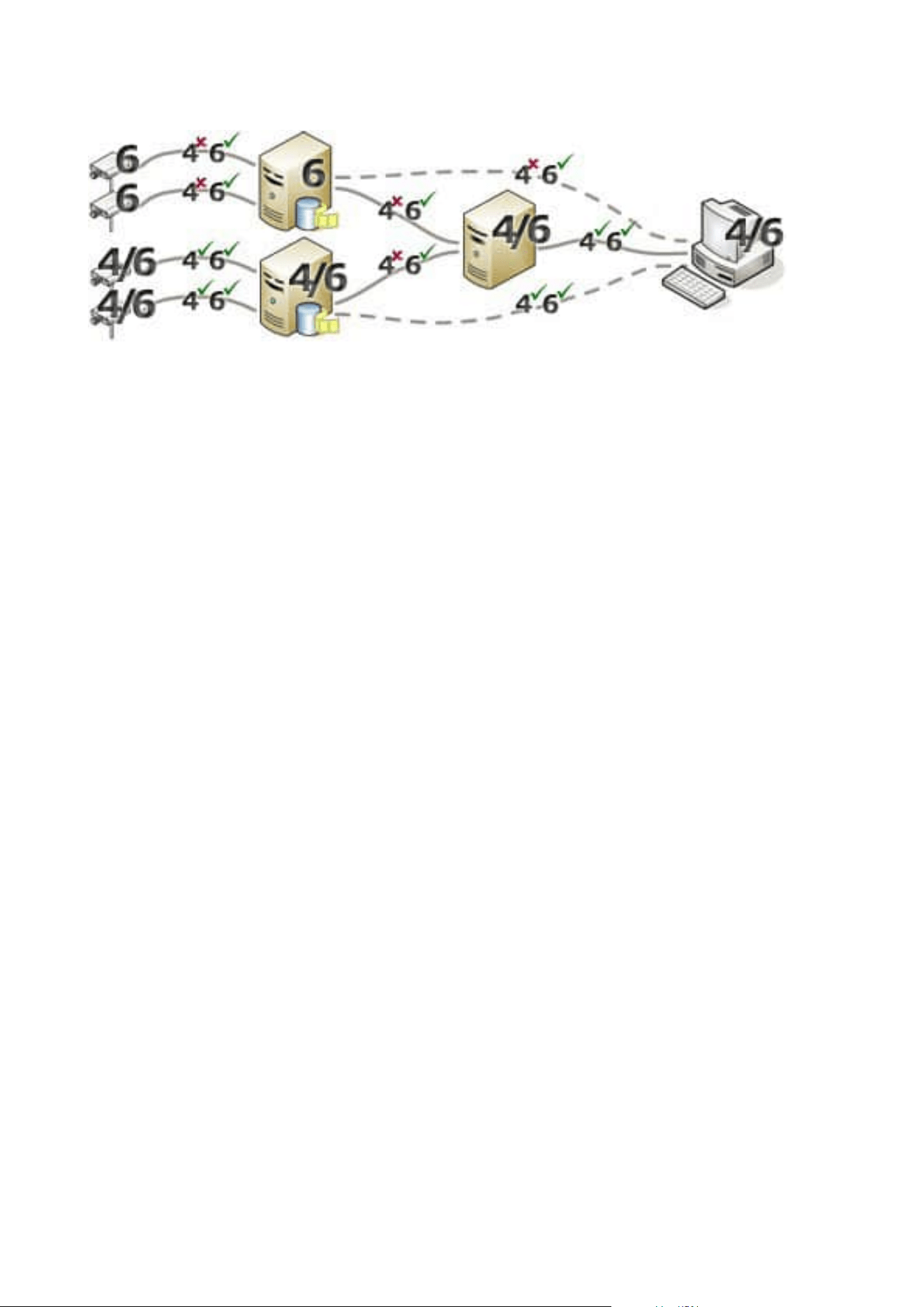
Example: Since one server in the system can only use IPv6, all communication with that server must use IPv6.
However, that server also determines the IP version for communication between all other servers in the
system.
Writing IPv6 addresses (explained)
An IPv6 address is usually written as eight blocks of four hexadecimal digits, with each block separated by a
colon.
Example: 2001:0B80:0000:0000:0000:0F80:3FA8:18AB
You may shorten addresses by eliminating leading zeros in a block. Also, note that some of the four-digit
blocks may consist of zeros only. If any number of such 0000 blocks are consecutive, you may shorten
addresses by replacing the 0000 blocks with two colons as long as there is only one such double colon in the
address.
Example:
2001:0B80:0000:0000:0000:0F80:3FA8:18AB can be shortened to
2001:B80:0000:0000:0000:F80:3FA8:18AB if removing the leading zeros, or to
2001:0B80::0F80:3FA8:18AB if removing the 0000 blocks, or even to
2001:B80::F80:3FA8:18AB if removing the leading zeros as well as the 0000 blocks.
Using IPv6 Addresses in URLs
IPv6 addresses contain colons. Colons, however, are also used in other types of network addressing syntax. For
example, IPv4 uses a colon to separate IP address and port number when both are used in a URL. IPv6 has
inherited this principle. Therefore, to avoid confusion, square brackets are put around IPv6 addresses when
they are used in URLs.
Example of a URL with an IPv6 address:
http://[2001:0B80:0000:0000:0000:0F80:3FA8:18AB], which may of course be shortened to, for example, http://
[2001:B80::F80:3FA8:18AB]
Example of a URL with an IPv6 address and a port number:
http://[2001:0B80:0000:0000:0000:0F80:3FA8:18AB]:1234, which may of course be shortened to, for example,
http://[2001:B80::F80:3FA8:18AB]:1234
Administrator manual | XProtect® VMS 2023 R1
125 | Requirements and considerations

For more information about IPv6, see, for example, the IANA website (https://www.iana.org/numbers/). IANA,
the Internet Assigned Numbers Authority, is the organization responsible for the global coordination of IP
addressing.
Virtual servers
You can run all system components on virtualized Windows
®
servers, such as VMware
®
and Microsoft
®
Hyper-V
®
.
Virtualization is often preferred to better utilize hardware resources. Normally, virtual servers running on the
hardware host server do not load the virtual server to a great extent, and often not at the same time. However,
recording servers record all cameras and video streams. This puts high load on CPU, memory, network, and
storage system. So, when run on a virtual server, the normal gain of virtualization disappears to a large extent,
since - in many cases - it uses all available resources.
If run in a virtual environment, it is important that the hardware host has the same amount of physical
memory as allocated for the virtual servers and that the virtual server running the recording server is allocated
enough CPU and memory - which it is not by default. Typically, the recording server needs 2-4 GB depending
on configuration. Another bottleneck is network adapter allocation and hard disk performance. Consider
allocating a physical network adapter on the host server of the virtual server running the recording server. This
makes it easier to ensure that the network adapter is not overloaded with traffic to other virtual servers. If the
network adapter is used for several virtual servers, the network traffic might result in the recording server not
retrieving and recording the configured number of images.
Multiple management servers (clustering) (explained)
The management server can be installed on multiple servers within a cluster of servers. This ensures that the
system has very little downtime. If a server in the cluster fails, another server in the cluster automatically takes
over the failed server's job running the management server.
It is only possible to have one active management server per surveillance setup, but other management
servers may be set up to take over in case of failure.
By default, the Management Server service limits the number of times a failover occurs
to twice within a six-hour period. If this is exceeded, the Management Server services are
not automatically started by the clustering service. This limit can be changed to better fit
your needs.
Administrator manual | XProtect® VMS 2023 R1
126 | Requirements and considerations
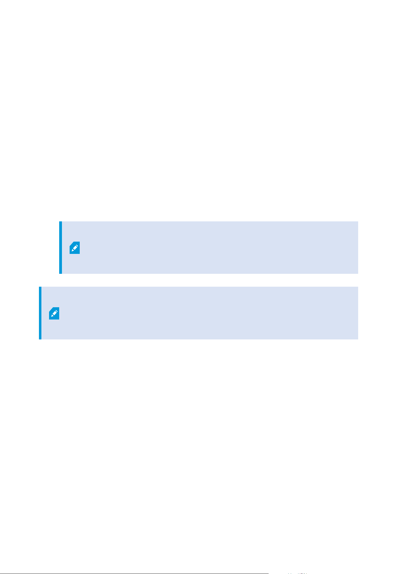
Requirements for clustering
l
Two machines with Microsoft Windows Server 2016 or newer. Make sure that:
l
All servers that you want to add as cluster nodes are running the same version of Windows
Server
l
All servers that you want to add as cluster nodes are joined to the same domain
l
You have log-in access to the Windows account as the local administrator
About clusters in Microsoft Windows Servers, see Failover clusters https://docs.microsoft.com/en-
us/windows-server/failover-clustering/create-failover-cluster.
l
A Microsoft SQL Server installation
Either an external SQL Server and database installed outside the server cluster or an internalSQL
Server service (clustered) within the server cluster (creating an internal SQL Server service requires the
use of the Microsoft® SQL Server® Standard or Microsoft® SQL Server® Enterprise edition, which can
work as a clustered SQL Server).
When connecting the management server to the database, depending on your
system configuration password settings, you may be asked to provide the current
system configuration password. See System configuration password (explained)
on page 315.
If you work in a failover cluster environment, it is recommended that you pause the
cluster before you start tasks in the Server Configurator. This is because the Server
Configurator may need to stop services while applying changes and the failover cluster
environment may interfere with this operation.
Protect recording databases from corruption
Camera databases can become corrupted. Several database repair options exist to resolve such a problem. but
Milestone recommends that you take steps to ensure that your camera databases do not become corrupted.
Hard disk failure: protect your drives
Hard disk drives are mechanical devices and are vulnerable to external factors. The following are examples of
external factors which may damage hard disk drives and lead to corrupt camera databases:
l
Vibration (make sure the surveillance system server and its surroundings are stable)
l
Strong heat (make sure the server has adequate ventilation)
l
Strong magnetic fields (avoid)
Administrator manual | XProtect® VMS 2023 R1
127 | Requirements and considerations

l
Power outages (make sure you use an Uninterruptible Power Supply (UPS))
l
Static electricity (make sure you ground yourself if you are going to handle a hard disk drive)
l
Fire, water, etc. (avoid)
Windows Task Manager: be careful when you end processes
When you work in Windows Task Manager, be careful not to end any processes which affect the surveillance
system. If you end an application or system service by clicking End Process in the Windows Task Manager, the
process is not given the chance to save its state or data before it is terminated. This may lead to corrupt
camera databases.
Windows Task Manager typically displays a warning if you attempt to end a process. Unless you are absolutely
sure that ending the process is not going to affect the surveillance system, click No when the warning message
asks you if you really want to terminate the process.
Power outages: use a UPS
The single-most common reason for corrupt databases is the recording server being shut down abruptly,
without files being saved and without the operating system being closed down properly. This may happen due
to power outages, due to somebody accidentally pulling out the server's power cable, or similar.
The best way of protecting your recording servers from being shut down abruptly is to equip each of your
recording servers with a UPS (Uninterruptible Power Supply).
The UPS works as a battery-driven secondary power source, providing the necessary power for saving open
files and safely powering down your system in the event of power irregularities. UPSs vary in sophistication,
but many UPSs include software for automatically saving open files, for alerting system administrators, etc.
Selecting the correct type of UPS for your organization's environment is an individual process. When you
assess your needs, however, bear in mind the amount of runtime you require the UPS to be able to provide if
the power fails. Saving open files and shutting down an operating system properly may take several minutes.
SQL database transaction log (explained)
Each time a change is written to an SQL database, the SQL database logs this change in its transaction log.
With the transaction log, you can roll back and undo changes to the SQL database through Microsoft® SQL
Server Management Studio. By default, the SQL database stores its transaction log indefinitely which over time
means that the transaction log has more and more entries. The transaction log is by default located on the
system drive, and if the transaction log keeps growing, it may prevent Windows from running properly.
To avoid such a scenario, flushing the transaction log regularly is a good idea. Flushing it does not make the
transaction log file smaller, but cleans its content and thereby prevents it from growing out of control. Your
VMS system does not flush transaction logs. In SQL Server, there are ways of flushing the transaction log. Visit
the Microsoft support page https://docs.microsoft.com/en-us/sql/relational-databases/logs/the-transaction-
log-sql-server?view=sql-server-2017 and search for Transaction log truncation.
Administrator manual | XProtect® VMS 2023 R1
128 | Requirements and considerations

Minimum system requirements
For information about the system requirements for the various VMS applications and system components, go
to the Milestone website (https://www.milestonesys.com/systemrequirements/).
Before you start installation
Milestone recommends that you go through the requirements described in the next sections, before you start
the actual installation.
Prepare your servers and network
Operating system
Make sure that all servers have a clean installation of a Microsoft Windows operating system, and that it is
updated with all the latest Windows updates.
For information about the system requirements for the various VMS applications and system components, go
to the Milestone website (https://www.milestonesys.com/systemrequirements/).
Microsoft
®
.NET Framework
Check that all servers have Microsoft .NET Framework 4.8 or higher installed.
Network
Assign static IP addresses or make DHCP reservations to all system components and cameras. To make sure
that sufficient bandwidth is available on your network, you must understand how and when the system
consumes bandwidth. The main load on your network consists of three elements:
l
Camera video streams
l
Clients displaying video
l
Archiving of recorded video
The recording server retrieves video streams from the cameras, which results in a constant load on the
network. Clients that display video consume network bandwidth. If there are no changes in the content of the
client views, the load is constant. Changes in view content, video search, or playback, make the load dynamic.
Archiving of recorded video is an optional feature that lets the system move recordings to a network storage if
there is not enough space in the internal storage system of the computer. This is a scheduled job that you have
to define. Typically, you archive to a network drive which makes it a scheduled dynamic load on the network.
Your network must have bandwidth headroom to cope with these peaks in the traffic. This enhances the
system responsiveness and general user experience.
Administrator manual | XProtect® VMS 2023 R1
129 | Requirements and considerations

Prepare Active Directory
If you want to add users to your system through the Active Directory service, you must have a server with
Active Directory installed and acting as domain controller available on your network.
For easy user and group management, Milestone recommends that you have Microsoft Active Directory
®
installed and configured before you install your XProtect system. If you add the management server to the
Active Directory after installing your system, you must reinstall the management server, and replace users with
new Windows users defined in the Active Directory.
Basic users are not supported in Milestone Federated Architecture systems, so if you plan to use Milestone
Federated Architecture, you must add users as Windows users through the Active Directory service. If you do
not install Active Directory, follow the steps in
Installation for workgroups on page 168 when you install.
Installation method
As part of the installation wizard, you must decide which installation method to use. You should base your
selection on your organization's needs, but it is very likely that you already decided on the method when you
purchased the system.
Options Description
Single
Computer
Installs all server and client components, as well as the SQL Server on the current
computer.
When the installation completes, you get the possibility to configure your system
through a wizard. If you agree to continue, the recording server scans your network for
hardware, and you can select which hardware devices to add to your system. The max
number of hardware devices that can be added in the configuration wizard depends on
your base license. Also, cameras are preconfigured in views, and a default Operator role
is created. After installation, XProtect Smart Client opens, and you are ready to use the
system.
Custom
The management server is always selected in the system component list and is always
installed, but you can select freely what to install on the current computer among the
other server and client components.
By default, the recording server is not selected in the component list, but you can change
this. You can install the not selected components on other computers afterwards.
Administrator manual | XProtect® VMS 2023 R1
130 | Requirements and considerations
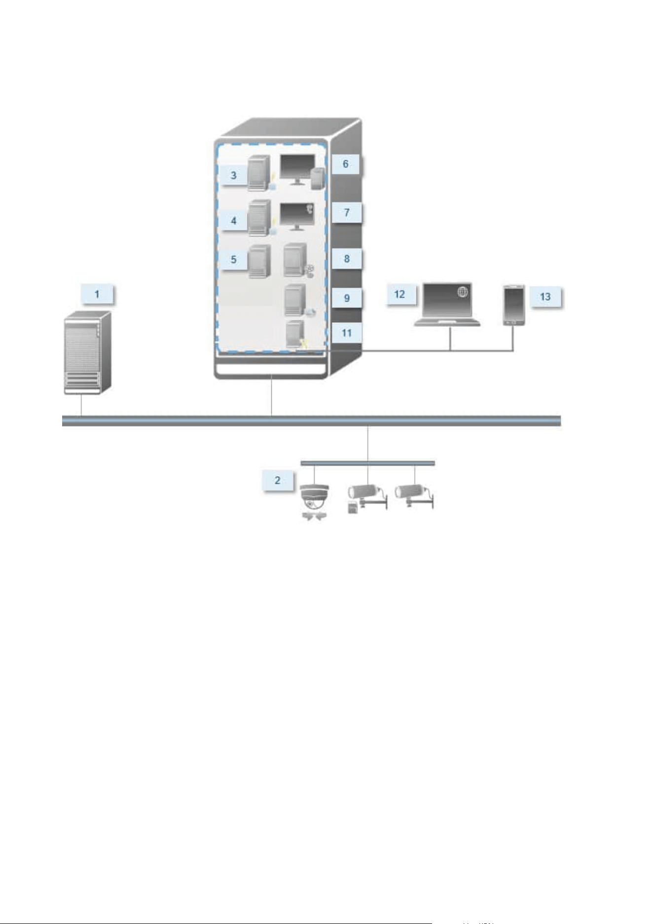
Single Computer installation
Typical system components in a system:
1. Active Directory
2. Devices
3. Server with SQL Server
4. Event server
5. Log server
6. XProtect Smart Client
7. Management Client
8. Management server
9. Recording server
Administrator manual | XProtect® VMS 2023 R1
131 | Requirements and considerations
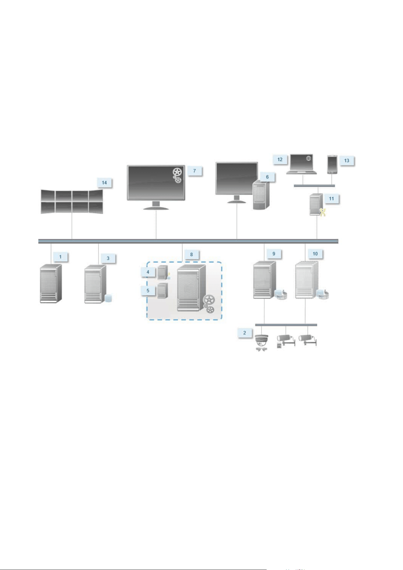
10. Failover recording server
11. XProtect Mobile server
12. XProtect Web Client
13. XProtect Mobile client
14. XProtect Smart Client with XProtect Smart Wall
Custom installation - example of distributed system components
Decide on a SQL Server edition
Microsoft® SQL Server® Express is a free edition of SQL Server and is easy to install and prepare for use
compared to the other SQL Server editions. During a Single computer installation, Microsoft SQL Server
Express is installed unless a SQL Server is already installed on the computer.
The XProtect VMS installation includes Microsoft SQL Server Express version 2019. Not all Windows operating
systems support this edition of SQL Server. Before you install XProtect VMS, verify that your operating system
supports SQL Server 2019. If your operating system does not support this edition of SQL Server, install a
supported edition of SQL Server before you start the XProtect VMS installation. For information about
supported SQL Server editions, see https://www.milestonesys.com/systemrequirements/.
Administrator manual | XProtect® VMS 2023 R1
132 | Requirements and considerations

For very large systems or systems with many transactions to and from the SQL databases, Milestone
recommends that you use a Microsoft® SQL Server® Standard or Microsoft® SQL Server® Enterprise edition
of the SQL Server on a dedicated computer on the network and on a dedicated hard disk drive that is not used
for other purposes. Installing the SQL Server on its own drive improves the entire system performance.
Select service account
As part of the installation, you are asked to specify an account to run the Milestone services on this computer.
The services always run on this account no matter which user is logged in. Make sure that the account has all
necessary user permissions, for example, the proper permissions to perform tasks, proper network and file
access, and access to network shared folders.
You can select either a predefined account, or a user account. Base your decision on the environment that you
want to install your system in:
Domain environment
In a domain environment:
l
Milestone recommends that you use the built-in Network Service account
It is easier to use even if you need to expand the system to multiple computers.
l
You can also use domain user accounts, but they are potentially more difficult to configure
Workgroup environment
In a workgroup environment, Milestone recommends that you use a local user account that has all necessary
permissions. This is often the administrator account.
If you have installed your system components on multiple computers, the selected user
account must be configured on all computers in your installations with identical user
name, password, and access permissions.
Kerberos authentication (explained)
Kerberos is a ticket-based network authentication protocol. It is designed to provide strong authentication for
client/server or server/server applications.
Use Kerberos authentication as an alternative to the older Microsoft NT LAN (NTLM) authentication protocol.
Kerberos authentication requires mutual authentication, where the client authenticates to the service and the
service authenticates to the client. This way you can authenticate more securely from XProtect clients to
XProtect servers without exposing your password.
Administrator manual | XProtect® VMS 2023 R1
133 | Requirements and considerations
To make mutual authentication possible in your XProtect VMS you must register Service Principal Names (SPN)
in the active directory. An SPN is an alias that uniquely identifies an entity such as a XProtect server service.
Every service that uses mutual authentication must have an SPN registered so that clients can identify the
service on the network. Without correctly registered SPNs, mutual authentication is not possible.
The table below lists the different Milestone services with corresponding port numbers you need to register:
Service Port number
Management Server - IIS 80 - Configurable
Management Server - Internal 8080
Recording Server - Data Collector 7609
Failover Server 8990
Event Server 22331
LPR Server 22334
The number of services you need to register in the active directory depends on your
current installation. Data Collector is installed automatically when installing the
Management Server, Recording Server, Event Server or Failover Server service.
You must register two SPNs for the user running the service: one with the host name and one with the fully
qualified domain name.
If you are running the service under a network user service account, you must register the two SPNs for each
computer running this service.
This is the Milestone SPN naming scheme:
VideoOS/[DNS Host Name]:[Port]
VideoOS/[Fully qualified domain name]:[Port]
The following is an example of SPNs for the Recording Server service running on a computer with the following
details:
Administrator manual | XProtect® VMS 2023 R1
134 | Requirements and considerations

Hostname: Record-Server1
Domain: Surveillance.com
SPNs to register:
VideoOS/Record-Server1:7609
VideoOS/Record-Server1.Surveillance.com:7609
Virus scanning exclusions (explained)
As is the case with any other database software, if an antivirus program is installed on a computer running
XProtect software, it is important that you exclude specific file types and folders, as well as certain network
traffic. Without implementing these exceptions, virus scanning uses a considerable amount of system
resources. On top of that, the scanning process can temporarily lock files, which could result in a disruption in
the recording process or even corruption of databases.
When you need to perform virus scanning, do not scan Recording Server folders that contain recording
databases (by default C:\mediadatabase\, as well as all subfolders). Also, avoid performing virus scanning on
archive storage directories.
Create the following additional exclusions:
l
File types: .blk, .idx, .pic
l
Folders and subfolders:
l
C:\Program Files\Milestone or C:\Program Files (x86)\Milestone
l
C:\ProgramData\Milestone\IDP\Logs
l
C:\ProgramData\Milestone\KeyManagement\Logs
l
C:\ProgramData\Milestone\MIPSDK
l
C:\ProgramData\Milestone\XProtect Data Collector Server\Logs
l
C:\ProgramData\Milestone\XProtect Event Server\Logs
l
C:\ProgramData\Milestone\XProtect Log Server
l
C:\ProgramData\Milestone\XProtect Management Server\Logs
l
C:\ProgramData\Milestone\XProtect Mobile Server\Logs
l
C:\ProgramData\Milestone\XProtect Recording Server\Logs
l
C:\ProgramData\Milestone\XProtect Report Web Server\Logs
l
C:ProgramData\Milestone\XProtect Recording Server\Secure\TablesDb
Administrator manual | XProtect® VMS 2023 R1
135 | Requirements and considerations

l
Exclude network scanning on the following TCP ports:
Product TCP ports
XProtect VMS 80, 8080, 7563, 25, 21, 9000
XProtect Mobile 8081
or
l
Exclude network scanning of the following processes:
Product Processes
XProtect VMS
VideoOS.Recorder.Service.exe, VideoOS.Server.Service.exe, VideoOS.
Administration.exe
XProtect
Mobile
VideoOS.MobileServer.Service.exe
Your organization may have strict guidelines regarding virus scanning, but it is important that you exclude the
above folders and files from virus scanning.
How can XProtect VMS be configured to run in FIPS 140-2 compliant mode?
In order to run XProtect VMS in a FIPS 140-2 mode of operation you must:
l
Run Windows operating system in FIPS 140-2 approved mode of operation. See the Microsoft site for
information on enabling FIPS.
l
Ensure standalone third-party integrations can run on a FIPS enabled Windows operating system
l
Connect to devices in a way that ensures a FIPS 140-2 compliant mode of operation
l
Ensure that data in the media database is encrypted with FIPS 140-2 compliant ciphers
This is done by running the media database upgrade tool. For detailed information on how to configure
your XProtect VMS to run in FIPS 140-2 compliant mode, see the FIPS 140-2 compliance section in the
hardening guide.
Administrator manual | XProtect® VMS 2023 R1
136 | Requirements and considerations

Before you install XProtect VMS on a FIPS enabled system
While new XProtect VMS installations can be done on computers that are FIPS-enabled, you cannot upgrade
XProtect VMS when FIPS is enabled on the Windows operating system.
If you are upgrading, before you install, disable the Windows FIPS security policy on all of the computers that
are part of the VMS, including the computer that hosts the SQL server.
The XProtect VMS installer checks the FIPS security policy and will prevent the installation from starting if FIPS
is enabled.
But, if you are upgrading from XProtect VMS version 2020 R3 and after, you do not need to disable FIPS.
After you have installed the XProtect VMS components on all of the computers and prepared the system for
FIPS, you can enable the FIPS security policy on Windows on all of the computers in your VMS.
For detailed information on how to configure your XProtect VMS to run in FIPS 140-2 compliant mode, see the
FIPS 140-2 compliance section in the hardening guide.
Register Software License Code
Before you install, you must have the name and location of the software license file that you received from
Milestone.
You can install a free version of XProtect Essential+. This version provides you with limited capabilities of the
XProtect VMS for a limited number of cameras. You must have internet connection to install XProtect
Essential+.
The Software License Code (SLC) is printed on your order confirmation and the software license file is named
after your SLC.
Milestone recommends that you register your SLC on our website (https://online.milestonesys.com/) before
installation. Your reseller may have done that for you.
Device drivers (explained)
Your system uses video device drivers to control and communicate with the camera devices connected to a
recording server. You must install device drivers on each recording server on your system.
From the 2018 R1 release, the device drivers are split into two device packs: the regular device pack with newer
drivers and a legacy device pack with older drivers.
The regular device pack is installed automatically when you install the recording server. Later, you can update
the drivers by downloading and installing a newer version of the device pack. Milestone releases new versions
of device drivers regularly and makes them available on the download page
(https://www.milestonesys.com/downloads/) on our website as device packs. When you update a device pack,
you can install the latest version on top of any version you may have installed.
Administrator manual | XProtect® VMS 2023 R1
137 | Requirements and considerations

The legacy device pack can only be installed if the system has a regular device pack installed. The drivers from
the legacy device pack are automatically installed if a previous version is already installed on your system. It is
available for manual download and installation on the software download page
(https://www.milestonesys.com/downloads/).
Stop the Recording Server service before you install, otherwise you need to restart the computer.
To ensure best performance, always use the latest version of device drivers.
Requirements for offline installation
If you install the system on a server that is offline, you need the following:
l
The Milestone XProtect VMS Products 2023 R1 System Installer.exe file
l
The software license file (SLC) for your XProtect system
l
OS installation media including the required .NET version
(https://www.milestonesys.com/systemrequirements/)
Secure communication (explained)
Hypertext Transfer Protocol Secure (HTTPS) is an extension of the Hypertext Transfer Protocol (HTTP) for
secure communication over a computer network. In HTTPS, the communication protocol is encrypted using
Transport Layer Security (TLS), or its predecessor, Secure Sockets Layer (SSL).
In XProtect VMS, secure communication is obtained by using TLS/SSL with asymmetric encryption (RSA).
TLS/SSL uses a pair of keys—one private, one public—to authenticate, secure, and manage secure connections.
A certificate authority (CA) is anyone who can issue root certificates. This can be an internet service that issues
root certificates, or anyone who manually generates and distributes a certificate. A CA can issue certificates to
web services, that is to any software using https communication. This certificate contains two keys, a private
key and a public key. The public key is installed on the clients of a web service (service clients) by installing a
public certificate. The private key is used for signing server certificates that must be installed on the server.
Whenever a service client calls the web service, the web service sends the server certificate, including the
public key, to the client. The service client can validate the server certificate using the already installed public
CA certificate. The client and the server can now use the public and private server certificates to exchange a
secret key and thereby establish a secure TLS/SSL connection.
For manually distributed certificates, certificates must be installed before the client can make such a
verification.
See Transport Layer Security for more information about TLS.
Administrator manual | XProtect® VMS 2023 R1
138 | Requirements and considerations

Certificates have an expiry date. XProtect VMS will not warn you when a certificate is
about to expire. If a certificate expires:
• The clients will no longer trust the recording server with the expired certificate and
thus cannot communicate with it
• The recording servers will no longer trust the management server with the expired
certificate and thus cannot communicate with it
• The mobile devices will no longer trust the mobile server with the expired certificate
and thus cannot communicate with it
To renew the certificates, follow the steps in this guide as you did when you created
certificates.
For more information, see the certificates guide about how to secure your XProtect VMS installations.
Administrator manual | XProtect® VMS 2023 R1
139 | Requirements and considerations

Installation
Install a new XProtect system
Install XProtect Essential+
You can install a free version of XProtect Essential+. This version provides you with limited capabilities of the
XProtect VMS for a limited number of cameras. You must have internet connection to install XProtect
Essential+.
This version is installed on a single computer, using the Single computer installation option. The Single
computer option installs all server and client components on the current computer.
Milestone recommends that you read the following section carefully before you install:
Before you start installation on page 129.
For FIPS installations, you cannot upgrade XProtect VMS when FIPS is enabled on the
Windows operating system. Before you install, disable the Windows FIPS security policy
on all of the computers that are part of the VMS, including the computer that hosts the
SQL server. But, if you are upgrading from XProtect VMS version 2020 R3 and after, you
do not need to disable FIPS. For detailed information on how to configure your XProtect
VMS to run in FIPS 140-2 compliant mode, see the FIPS 140-2 compliance section in the
hardening guide.
After initial installation, you can continue with the configuration wizard. Depending on your hardware and
configuration, the recording server scans your network for hardware. You can then select which hardware
devices to add to your system. Cameras are preconfigured in views, and you have the option to enable other
devices such as microphones and speakers. You also have the option of adding users to the system with either
an operator role or an administrator role. After installation, XProtect Smart Client opens, and you are ready to
use the system.
Otherwise, if you close the installation wizard, XProtect Management Client opens, where you can make
manual configurations such as add hardware devices and users to the system.
If you upgrade from a previous version of the product, the system does not scan for
hardware or create new views and user profiles.
Administrator manual | XProtect® VMS 2023 R1
140 | Installation
1. Download the software from the internet (https://www.milestonesys.com/downloads/) and run the
Milestone XProtect VMS Products 2023 R1 System Installer.exe file.
2. The installation files unpack. Depending on the security settings, one or more Windows
®
security
warnings appear. Accept these and the unpacking continues.
3. When done, the Milestone XProtect VMS installation wizard appears.
1. Select the Language to use during the installation (this is not the language that your system
uses once installed; this is selected later). Click Continue.
2. Read the Milestone End-user License Agreement. Select the I accept the terms in the license
agreement check box and click Continue.
3. On the Privacy settings page, select whether you want to share usage data, and click Continue.
You must not enable data collection if you want the system to have an EU
GDPR-compliant installation. For more information about data protection
and the usage data collection, see the GDPRprivacy guide.
You can always change your privacy setting later. See also System settings
(Options dialog box).
4. Click the XProtect Essential+ link to download a free license file.
The free license file is downloaded and appears in the Enter or browse to the location of the
license file field. Click Continue.
4. Select Single computer.
A list of components to install appears (you cannot edit this list). Click Continue.
5. On the Assign a system configuration password page, enter a password that protects your system
configuration. You will need this password in case of system recovery or when expanding your system,
for example when adding clusters.
It is important that you save this password and keep it safe. If you lose this
password, you may compromise your ability to recover your system
configuration.
If you do not want your system configuration to be password protected, select I choose not to use a
system configuration password and understand that the system configuration will not be
encrypted.
Click Continue.
Administrator manual | XProtect® VMS 2023 R1
141 | Installation

6. On the Assign a mobile server data protection password page, enter a password to encrypt your
investigations. As a system administrator, you will need to enter this password to access the mobile
server data in case of system recovery or when expanding your system with additional mobile servers.
You must save this password and keep it safe. Failure to do so may compromise
your ability to recover mobile server data.
If you do not want your investigations to be password-protected, select I choose not to use a mobile
server data protection password, and I understand that investigations will not be encrypted.
Click Continue.
7. On the Specify recording server settings page, specify the different recording server settings:
1. In the Recording server name field, enter the name of the recording server. The default is the
name of the computer.
2. The Management server address field shows the address and port number of the management
server: localhost:80.
3. In the Select your media database location field, select the location where you want to save
your video recording. Milestone recommends that you save your video recordings in a separate
location from where you install the software and not on the system drive. The default location is
the drive with the most space available.
4. In Retention time for video recordings field, define for how long you want to save the
recordings. You can enter from between 1 and 365,000 days, where 7 days is the default
retention time.
5. Click Continue.
Administrator manual | XProtect® VMS 2023 R1
142 | Installation

8. On the Select encryption page, you can secure the communication flows:
l
Between the recording servers, data collectors, and the management server
To enable encryption for internal communication flows, in the Server certificate section, select a
certificate.
If you encrypt the connection from the recording server to the
management server, the system requires that you also encrypt the
connection from the management server to the recording server.
l
Between the recording servers and clients
To enable encryption between recording servers and client components that retrieve data
streams from the recording server, in the Streaming media certificate section, select a
certificate.
l
Between the mobile server and clients
To enable encryption between client components that retrieve data streams from the mobile
server, in the Mobile streaming media certificate section, select a certificate.
l
Between the event server and components that communicate with the event server
To enable encryption between the event server and components that communicate with the
event server, including the LPR Server, in the Event server and add-ons section, select a
certificate.
You can use the same certificate file for all system components or use different certificate files
depending on the system components.
For more information about preparing your system for secure communication, see:
l
Secure communication (explained) on page 138
l
The Milestone guide about certificates
You can also enable encryption after installation from the Server Configurator in the Management
Server Manager tray icon in the notification area.
Administrator manual | XProtect® VMS 2023 R1
143 | Installation

9. On the Select file location and product language page, do the following:
1. In the File location field, select the location where you want to install the software.
If any Milestone XProtect VMS product is already installed on the
computer, this field is disabled. The field displays the location where the
component will be installed.
2. In Product language, select the language in which to install your XProtect product.
3. Click Install.
The software now installs. If not already installed on the computer, Microsoft® SQL Server® Express
and Microsoft IIS areautomatically installed during the installation.
10. You may be prompted to restart the computer. After restarting your computer, depending on the
security settings, one or more Windows security warnings may appear. Accept these and the
installation completes.
11. When the installation completes, a list shows the components that are installed on the computer.
Click Continue to add hardware and users to the system.
If you click Close now, you bypass the configuration wizard and XProtect
Management Client opens. You can configure the system, for example add
hardware and users to the system, in Management Client.
12. On the Enter user names and passwords for hardware page, enter the user names and passwords for
hardware that you have changed from the manufacturer defaults.
The installer scans the network for this hardware as well as hardware with manufacturer default
credentials.
Click Continue and wait while the system scans for hardware.
13. On the Select the hardware to add to the system page, select the hardware that you want to add to
the system. Click Continue and wait while the system adds the hardware.
Administrator manual | XProtect® VMS 2023 R1
144 | Installation
14. On the Configure the devices page, you can give the hardware descriptive names by clicking the edit
icon next to the hardware name. This name is then prefixed to the hardware devices.
Expand the hardware node to enable or disable the hardware devices, such as cameras, speakers, and
microphones.
Cameras are enabled by default, and speakers and microphones are disabled by
default.
Click Continue and wait while the system configures the hardware.
15. On the Add users page, you can add users to the system as Windows users or basic users. The users
can have either the Administrators role or the Operators role.
Define the user and click Add.
When you are done adding users, click Continue.
16. When the installation and initial configuration are done, the Configuration is complete page appears,
where you see:
l
A list of hardware devices that are added to the system
l
A list of users who are added to the system
l
Addresses to the XProtect Web Client and XProtect Mobile client, which you can share with your
users
When you click Close, XProtect Smart Client opens and is ready to use.
Install your system - Single computer option
The Single computer option installs all server and client components on the current computer.
Milestone recommends that you read the following section carefully before you install:
Before you start installation on page 129.
For FIPS installations, you cannot upgrade XProtect VMS when FIPS is enabled on the
Windows operating system. Before you install, disable the Windows FIPS security policy
on all of the computers that are part of the VMS, including the computer that hosts the
SQL server. But, if you are upgrading from XProtect VMS version 2020 R3 and after, you
do not need to disable FIPS. For detailed information on how to configure your XProtect
VMS to run in FIPS 140-2 compliant mode, see the FIPS 140-2 compliance section in the
hardening guide.
Administrator manual | XProtect® VMS 2023 R1
145 | Installation
After initial installation, you can continue with the configuration wizard. Depending on your hardware and
configuration, the recording server scans your network for hardware. You can then select which hardware
devices to add to your system. Cameras are preconfigured in views, and you have the option to enable other
devices such as microphones and speakers. You also have the option of adding users to the system with either
an operator role or an administrator role. After installation, XProtect Smart Client opens, and you are ready to
use the system.
Otherwise, if you close the installation wizard, XProtect Management Client opens, where you can make
manual configurations such as add hardware devices and users to the system.
If you upgrade from a previous version of the product, the system does not scan for
hardware or create new views and user profiles.
1. Download the software from the internet (https://www.milestonesys.com/downloads/) and run the
Milestone XProtect VMS Products 2023 R1 System Installer.exe file.
2. The installation files unpack. Depending on the security settings, one or more Windows
®
security
warnings appear. Accept these and the unpacking continues.
3. When done, the Milestone XProtect VMS installation wizard appears.
1. Select the Language to use during the installation (this is not the language that your system
uses once installed; this is selected later). Click Continue.
2. Read the Milestone End-user License Agreement. Select the I accept the terms in the license
agreement check box and click Continue.
3. On the Privacy settings page, select whether you want to share usage data, and click Continue.
You must not enable data collection if you want the system to have an EU
GDPR-compliant installation. For more information about data protection
and the usage data collection, see the GDPRprivacy guide.
You can always change your privacy setting later. See also System settings
(Options dialog box).
4. In the Enter or browse to the location of the license file, enter your license file from your
XProtect provider. Alternatively, browse to the file location or click the XProtect Essential+ link
to download a free license file. For limitations to the free XProtect Essential+ product, see the
Product comparison on page 107. The system verifies your license file before you can continue.
Click Continue.
Administrator manual | XProtect® VMS 2023 R1
146 | Installation
4. Select Single computer.
A list of components to install appears (you cannot edit this list). Click Continue.
5. On the Assign a system configuration password page, enter a password that protects your system
configuration. You will need this password in case of system recovery or when expanding your system,
for example when adding clusters.
It is important that you save this password and keep it safe. If you lose this
password, you may compromise your ability to recover your system
configuration.
If you do not want your system configuration to be password protected, select I choose not to use a
system configuration password and understand that the system configuration will not be
encrypted.
Click Continue.
6. On the Assign a mobile server data protection password page, enter a password to encrypt your
investigations. As a system administrator, you will need to enter this password to access the mobile
server data in case of system recovery or when expanding your system with additional mobile servers.
You must save this password and keep it safe. Failure to do so may compromise
your ability to recover mobile server data.
If you do not want your investigations to be password-protected, select I choose not to use a mobile
server data protection password, and I understand that investigations will not be encrypted.
Click Continue.
Administrator manual | XProtect® VMS 2023 R1
147 | Installation

7. On the Specify recording server settings page, specify the different recording server settings:
1. In the Recording server name field, enter the name of the recording server. The default is the
name of the computer.
2. The Management server address field shows the address and port number of the management
server: localhost:80.
3. In the Select your media database location field, select the location where you want to save
your video recording. Milestone recommends that you save your video recordings in a separate
location from where you install the software and not on the system drive. The default location is
the drive with the most space available.
4. In Retention time for video recordings field, define for how long you want to save the
recordings. You can enter from between 1 and 365,000 days, where 7 days is the default
retention time.
5. Click Continue.
Administrator manual | XProtect® VMS 2023 R1
148 | Installation

8. On the Select encryption page, you can secure the communication flows:
l
Between the recording servers, data collectors, and the management server
To enable encryption for internal communication flows, in the Server certificate section, select a
certificate.
If you encrypt the connection from the recording server to the
management server, the system requires that you also encrypt the
connection from the management server to the recording server.
l
Between the recording servers and clients
To enable encryption between recording servers and client components that retrieve data
streams from the recording server, in the Streaming media certificate section, select a
certificate.
l
Between the mobile server and clients
To enable encryption between client components that retrieve data streams from the mobile
server, in the Mobile streaming media certificate section, select a certificate.
l
Between the event server and components that communicate with the event server
To enable encryption between the event server and components that communicate with the
event server, including the LPR Server, in the Event server and add-ons section, select a
certificate.
You can use the same certificate file for all system components or use different certificate files
depending on the system components.
For more information about preparing your system for secure communication, see:
l
Secure communication (explained) on page 138
l
The Milestone guide about certificates
You can also enable encryption after installation from the Server Configurator in the Management
Server Manager tray icon in the notification area.
Administrator manual | XProtect® VMS 2023 R1
149 | Installation
9. On the Select file location and product language page, do the following:
1. In the File location field, select the location where you want to install the software.
If any Milestone XProtect VMS product is already installed on the
computer, this field is disabled. The field displays the location where the
component will be installed.
2. In Product language, select the language in which to install your XProtect product.
3. Click Install.
The software now installs. If not already installed on the computer, Microsoft® SQL Server® Express
and Microsoft IIS areautomatically installed during the installation.
10. You may be prompted to restart the computer. After restarting your computer, depending on the
security settings, one or more Windows security warnings may appear. Accept these and the
installation completes.
11. When the installation completes, a list shows the components that are installed on the computer.
Click Continue to add hardware and users to the system.
If you click Close now, you bypass the configuration wizard and XProtect
Management Client opens. You can configure the system, for example add
hardware and users to the system, in Management Client.
12. On the Enter user names and passwords for hardware page, enter the user names and passwords for
hardware that you have changed from the manufacturer defaults.
The installer scans the network for this hardware as well as hardware with manufacturer default
credentials.
Click Continue and wait while the system scans for hardware.
13. On the Select the hardware to add to the system page, select the hardware that you want to add to
the system. Click Continue and wait while the system adds the hardware.
Administrator manual | XProtect® VMS 2023 R1
150 | Installation
14. On the Configure the devices page, you can give the hardware descriptive names by clicking the edit
icon next to the hardware name. This name is then prefixed to the hardware devices.
Expand the hardware node to enable or disable the hardware devices, such as cameras, speakers, and
microphones.
Cameras are enabled by default, and speakers and microphones are disabled by
default.
Click Continue and wait while the system configures the hardware.
15. On the Add users page, you can add users to the system as Windows users or basic users. The users
can have either the Administrators role or the Operators role.
Define the user and click Add.
When you are done adding users, click Continue.
16. When the installation and initial configuration are done, the Configuration is complete page appears,
where you see:
l
A list of hardware devices that are added to the system
l
A list of users who are added to the system
l
Addresses to the XProtect Web Client and XProtect Mobile client, which you can share with your
users
When you click Close, XProtect Smart Client opens and is ready to use.
Install your system - Custom option
The Custom option installs the management server, but you can select which other server and client
components you want to install on the current computer. By default, the recording server is not selected in the
component list. Depending on your selections, you can install the not selected system components on other
computers afterwards. For more information about each system component and their role, see Product
overview on page 31. Installation on other computers is done through the management server's download
web page named Download Manager. For more information about installation through the Download
Manager, see Download Manager/download web page on page 174.
Milestone recommends that you read the following section carefully before you install:
Before you start installation on page 129.
Administrator manual | XProtect® VMS 2023 R1
151 | Installation
For FIPS installations, you cannot upgrade XProtect VMS when FIPS is enabled on the
Windows operating system. Before you install, disable the Windows FIPS security policy
on all of the computers that are part of the VMS, including the computer that hosts the
SQL server. But, if you are upgrading from XProtect VMS version 2020 R3 and after, you
do not need to disable FIPS. For detailed information on how to configure your XProtect
VMS to run in FIPS 140-2 compliant mode, see the FIPS 140-2 compliance section in the
hardening guide.
1. Download the software from the internet (https://www.milestonesys.com/downloads/) and run the
Milestone XProtect VMS Products 2023 R1 System Installer.exe file.
2. The installation files unpack. Depending on the security settings, one or more Windows
®
security
warnings appear. Accept these and the unpacking continues.
3. When done, the Milestone XProtect VMS installation wizard appears.
1. Select the Language to use during the installation (this is not the language that your system
uses once installed; this is selected later). Click Continue.
2. Read the Milestone End-user License Agreement. Select the I accept the terms in the license
agreement check box and click Continue.
3. On the Privacy settings page, select whether you want to share usage data, and click Continue.
You must not enable data collection if you want the system to have an EU
GDPR-compliant installation. For more information about data protection
and the usage data collection, see the GDPRprivacy guide.
You can always change your privacy setting later. See also System settings
(Options dialog box).
4. In the Enter or browse to the location of the license file, enter your license file from your
XProtect provider. Alternatively, browse to the file location or click the XProtect Essential+ link
to download a free license file. For limitations to the free XProtect Essential+ product, see the
Product comparison on page 107. The system verifies your license file before you can continue.
Click Continue.
4. Select Custom. A list of components to be installed appears. Apart from the management server, all
components in the list are optional. The recording server and the mobile server are by default not
selected. Select the system components you want to install and click Continue.
Administrator manual | XProtect® VMS 2023 R1
152 | Installation
In the steps below, all system components are installed. For a more distributed
system, install fewer system components on this computer and the remaining
system components on other computers. If you cannot recognize an installation
step, it is likely because you have not selected to install the system component
that this page belongs to. In that case, continue to the next step. See also
Installing through Download Manager (explained) on page 156, Install a
recording server through Download Manager on page 158, and Installing silently
through a command line shell (explained) on page 163.
5. The Select a website on the IIS to use with your XProtect system page is shown only if you have
more than one IIS website available on the computer. You must select which website you will use with
your XProtect system. Select a website with HTTPS binding. Click Continue.
If Microsoft
®
IIS is not installed on the computer, it is installed.
6. On the Select Microsoft SQL Server page, select the SQL Server that you want to use. See also SQL
Server options during custom installation on page 156. Click Continue.
If you do not have a SQL Server on your local computer, you can install Microsoft
SQL Server Express, but in a larger distributed system you would typically use a
dedicated SQL Server on your network.
7. On the Select database page (only shown if you have selected an existing SQL Server), select or create
an SQL database for storing your system configuration. If you choose an existing SQL database, decide
whether to Keep or Overwrite existing data. If you are upgrading, select to keep existing data so you
do not lose your system configuration. See also SQL Server options during custom installation on page
156. Click Continue.
8. On the Assign a system configuration password page, enter a password that protects your system
configuration. You will need this password in case of system recovery or when expanding your system,
for example when adding clusters.
It is important that you save this password and keep it safe. If you lose this
password, you may compromise your ability to recover your system
configuration.
If you do not want your system configuration to be password protected, select I choose not to use a
system configuration password and understand that the system configuration will not be
encrypted.
Click Continue.
Administrator manual | XProtect® VMS 2023 R1
153 | Installation
9. On the Assign a mobile server data protection password page, enter a password to encrypt your
investigations. As a system administrator, you will need to enter this password to access the mobile
server data in case of system recovery or when expanding your system with additional mobile servers.
You must save this password and keep it safe. Failure to do so may compromise
your ability to recover mobile server data.
If you do not want your investigations to be password-protected, select I choose not to use a mobile
server data protection password, and I understand that investigations will not be encrypted.
Click Continue.
10. On the Select service account for recording server, select either This predefined account or This
account to select the service account for the recording server.
If needed, enter a password.
The user name for the account must be a single word. It must not have a space.
Click Continue.
11. On the Specify recording server settings page, specify the different recording server settings:
1. In the Recording server name field, enter the name of the recording server. The default is the
name of the computer.
2. The Management server address field shows the address and port number of the management
server: localhost:80.
3. In the Select your media database location field, select the location where you want to save
your video recording. Milestone recommends that you save your video recordings in a separate
location from where you install the software and not on the system drive. The default location is
the drive with the most space available.
4. In Retention time for video recordings field, define for how long you want to save the
recordings. You can enter from between 1 and 365,000 days, where 7 days is the default
retention time.
5. Click Continue.
Administrator manual | XProtect® VMS 2023 R1
154 | Installation

12. On the Select encryption page, you can secure the communication flows:
l
Between the recording servers, data collectors, and the management server
To enable encryption for internal communication flows, in the Server certificate section, select a
certificate.
If you encrypt the connection from the recording server to the
management server, the system requires that you also encrypt the
connection from the management server to the recording server.
l
Between the recording servers and clients
To enable encryption between recording servers and client components that retrieve data
streams from the recording server, in the Streaming media certificate section, select a
certificate.
l
Between the mobile server and clients
To enable encryption between client components that retrieve data streams from the mobile
server, in the Mobile streaming media certificate section, select a certificate.
l
Between the event server and components that communicate with the event server
To enable encryption between the event server and components that communicate with the
event server, including the LPR Server, in the Event server and add-ons section, select a
certificate.
You can use the same certificate file for all system components or use different certificate files
depending on the system components.
For more information about preparing your system for secure communication, see:
l
Secure communication (explained) on page 138
l
The Milestone guide about certificates
You can also enable encryption after installation from the Server Configurator in the Management
Server Manager tray icon in the notification area.
13. On the Select file location and product language page, select the File location for the program files.
If any Milestone XProtect VMS product is already installed on the computer, this
field is disabled. The field displays the location where the component will be
installed.
Administrator manual | XProtect® VMS 2023 R1
155 | Installation

14. In the Product language field, select the language in which to install your XProtect product. Click
Install.
The software now installs. When the installation completes, you see a list of successfully installed
system components. Click Close.
15. You may be prompted to restart the computer. After restarting your computer, depending on the
security settings, one or more Windows security warnings may appear. Accept these and the
installation completes.
16. Configure your system in Management Client. See Initial configuration tasks list on page 182.
17. Depending on your selections, install the remaining system components on other computers through
the Download Manager. See Installing through Download Manager (explained) on page 156.
SQL Server options during custom installation
Decide which SQL Server and database to use with the below options.
SQL Server options:
l
Install Microsoft® SQL Server® Express on this computer: This option is shown only if you do not
have a SQL Server installed on the computer
l
Use the SQL Server on this computer: This option is shown only if a SQL Server is already installed on
the computer
l
Select a SQL Server on your network through search: Enables you to search for all SQL Servers that
are discoverable on your network subnet
l
Select a SQL Server on your network: Enables you to enter the address (host name or IP address) of a
SQL Server that you might not be able to find through search
SQL database options:
l
Create new database: Mainly for new installations
l
Use existing database: Mainly for upgrades of existing installations. Milestone recommends that you
reuse the existing SQL database and keep the existing data in it, so you do not lose your system
configuration. You can also choose to overwrite the data in the SQL database
Install new XProtect components
Installing through Download Manager (explained)
If you want to install system components on computers other than where the management server is installed,
you must install these system components through the Management Server's download website Download
Manager.
Administrator manual | XProtect® VMS 2023 R1
156 | Installation
1. From the computer where Management Server is installed, go to the Management Server's download
web page. In Windows' Start menu, select Milestone > Administrative Installation Page and write
down or copy the internet address for later use when installing the system components on the other
computers. The address is typically http://[management server address]/installation/Admin/default-en-
US.htm.
2. Log in to each of the other computers to install one or more of the other system components:
l
Recording Server (For more information, see Install a recording server through Download
Manager on page 158 or Install a recording server silently on page 165)
l
Management Client (For more information, see Install a Management Client through Download
Manager on page 157)
l
Smart Client
l
Event Server
If you are installing the Event Server in a FIPS-compliant environment, you
must disable Windows FIPS 140-2 mode before installation.
l
Log Server (For more information, see Install a log server silently on page 167)
l
Mobile Server (For more information see the manual for XProtect Mobile server)
l
DLNA Server (For more information see the manual for XProtect DLNA Server)
3. Open an internet browser, enter the address of the Management Server's download web page into the
address field, and download the relevant installer.
4. Run the installer.
See Install your system - Custom option on page 151 if in doubt about the selections and settings in the
different installation steps.
Install a Management Client through Download Manager
If there are several administrators of the XProtect system or you simply want to manage the XProtect system
from multiple computers, you can install the Management Client by following the instructions below.
The Management Client is always installed on the management server.
1. From the computer where Management Server is installed, go to the Management Server's download
web page. In Windows' Start menu, select Milestone > Administrative Installation Page and write
down or copy the internet address for later use when installing the system components on the other
computers. The address is typically http://[management server address]/installation/Admin/default-en-
US.htm.
Administrator manual | XProtect® VMS 2023 R1
157 | Installation
2. Log into the computer where you want to install the system component.
1. Open an internet browser and enter the address of the Management Server's download web page into
the address field and press Enter.
3. Click All Languages for the Management Client installer. Run the downloaded file.
4. Click Yes to all warnings. Unpacking starts.
5. Select the language for the installer. Click Continue.
6. Read and accept the license agreement. Click Continue.
7. Select file location and product language. Click Install.
8. The installation is complete. A list of successfully installed components is displayed. Click Close.
9. Click the icon on the desktop to open the Management Client.
10. The Management Client login dialog appears.
11. Specify the host name or the IP address of your management server in the Computer field.
12. Select authentication, enter your user name and password. Click Connect. The Management Client
launches.
To read in details about the features in the Management Client and what you can accomplish with your
system, click Help in the tools menu.
Install a recording server through Download Manager
If your system components are distributed on separate computers, you can install the recording servers by
following the instructions below.
The recording server is already installed if you made a Single Computer installation, but
you can use the same instructions to add more recording servers if you need more
capacity.
If you need to install a failover recording server, see Install a failover recording server
through Download Manager on page 161.
1. From the computer where Management Server is installed, go to the Management Server's download
web page. In Windows' Start menu, select Milestone > Administrative Installation Page and write
down or copy the internet address for later use when installing the system components on the other
computers. The address is typically http://[management server address]/installation/Admin/default-en-
US.htm.
2. Log into the computer where you want to install the system component.
Administrator manual | XProtect® VMS 2023 R1
158 | Installation
3. Open an internet browser and enter the address of the Management Server's download web page into
the address field and press Enter.
4. Download the recording server installer by selecting All Languages below the Recording Server
Installer. Save the installer or run it directly from the web page.
5. Select the Language you want to use during the installation. Click Continue.
6. On the Select an installation type page, select:
Typical to install a recording server with default values, or
Custom to install a recording server with custom values.
7. On the Specify recording server settings page, specify the different recording server settings:
1. In the Recording server name field, enter the name of the recording server. The default is the
name of the computer.
2. The Management server address field shows the address and port number of the management
server: localhost:80.
3. In the Select your media database location field, select the location where you want to save
your video recording. Milestone recommends that you save your video recordings in a separate
location from where you install the software and not on the system drive. The default location is
the drive with the most space available.
4. In Retention time for video recordings field, define for how long you want to save the
recordings. You can enter from between 1 and 365,000 days, where 7 days is the default
retention time.
5. Click Continue.
8. The Recording servers IP addresses page is shown only if you selected Custom. Specify the number of
recording servers that you want to install on this computer. Click Continue.
9. On the Select service account for recording server, select either This predefined account or This
account to select the service account for the recording server.
If needed, enter a password.
The user name for the account must be a single word. It must not have a space.
Click Continue.
Administrator manual | XProtect® VMS 2023 R1
159 | Installation

10. On the Select encryption page, you can secure the communication flows:
l
Between the recording servers, data collectors, and the management server
To enable encryption for internal communication flows, in the Server certificate section, select a
certificate.
If you encrypt the connection from the recording server to the
management server, the system requires that you also encrypt the
connection from the management server to the recording server.
l
Between the recording servers and clients
To enable encryption between recording servers and client components that retrieve data
streams from the recording server, in the Streaming media certificate section, select a
certificate.
l
Between the mobile server and clients
To enable encryption between client components that retrieve data streams from the mobile
server, in the Mobile streaming media certificate section, select a certificate.
l
Between the event server and components that communicate with the event server
To enable encryption between the event server and components that communicate with the
event server, including the LPR Server, in the Event server and add-ons section, select a
certificate.
You can use the same certificate file for all system components or use different certificate files
depending on the system components.
For more information about preparing your system for secure communication, see:
l
Secure communication (explained) on page 138
l
The Milestone guide about certificates
You can also enable encryption after installation from the Server Configurator in the Management
Server Manager tray icon in the notification area.
11. On the Select file location and product language page, select the File location for the program files.
If any Milestone XProtect VMS product is already installed on the computer, this
field is disabled. The field displays the location where the component will be
installed.
Administrator manual | XProtect® VMS 2023 R1
160 | Installation

12. In the Product language field, select the language in which to install your XProtect product. Click
Install.
The software now installs. When the installation completes, you see a list of successfully installed
system components. Click Close.
13. When you have installed the recording server, you can check its state from the Recording Server
Manager tray icon and configure it in Management Client. For more information, see Initial
configuration tasks list on page 182.
Install a failover recording server through Download Manager
If you run workgroups, you must use the alternative installation method for failover
recording servers (see Installation for workgroups on page 168).
1. From the computer where Management Server is installed, go to the Management Server's download
web page. In Windows' Start menu, select Milestone > Administrative Installation Page and write
down or copy the internet address for later use when installing the system components on the other
computers. The address is typically http://[management server address]/installation/Admin/default-en-
US.htm.
Log into the computer where you want to install the system component.
2. Open an internet browser and enter the address of the Management Server's download web page into
the address field and press Enter.
3. Download the recording server installer by selecting All Languages below the Recording Server
Installer. Save the installer or run it directly from the web page.
4. Select the Language you want to use during the installation. Click Continue.
5. On the Select an installation type page, select Failover to install a recording server as a failover
recording server.
6. On the Specify recording server settings page, specify the different recording server settings. The
name of the failover recording server, the address of the management server, and the path to the
media database. Click Continue.
7. On the Select service account for recording server page and when installing a failover recording
server, you must use the particular user account named This account. This creates the failover user
account. If needed, enter a password and confirm this. Click Continue.
Administrator manual | XProtect® VMS 2023 R1
161 | Installation
8. On the Select encryption page, you can secure the communication flows:
l
Between the recording servers, data collectors, and the management server
To enable encryption for internal communication flows, in the Server certificate section, select a
certificate.
If you encrypt the connection from the recording server to the
management server, the system requires that you also encrypt the
connection from the management server to the recording server.
l
Between the recording servers and clients
To enable encryption between recording servers and client components that retrieve data
streams from the recording server, in the Streaming media certificate section, select a
certificate.
l
Between the mobile server and clients
To enable encryption between client components that retrieve data streams from the mobile
server, in the Mobile streaming media certificate section, select a certificate.
l
Between the event server and components that communicate with the event server
To enable encryption between the event server and components that communicate with the
event server, including the LPR Server, in the Event server and add-ons section, select a
certificate.
You can use the same certificate file for all system components or use different certificate files
depending on the system components.
For more information about preparing your system for secure communication, see:
l
Secure communication (explained) on page 138
l
The Milestone guide about certificates
You can also enable encryption after installation from the Server Configurator in the Management
Server Manager tray icon in the notification area.
9. On the Select file location and product language page, select the File location for the program files.
If any Milestone XProtect VMS product is already installed on the computer, this
field is disabled. The field displays the location where the component will be
installed.
Administrator manual | XProtect® VMS 2023 R1
162 | Installation

10. In the Product language field, select the language in which to install your XProtect product. Click
Install.
The software now installs. When the installation completes, you see a list of successfully installed
system components. Click Close.
11. When you have installed the failover recording server, you can check its state from the Failover Server
service tray icon and configure it in Management Client. For more information, see Initial configuration
tasks list on page 182.
Installing XProtect VMS using non-default ports
An installation of XProtect VMS requires specific ports. In particular, the Management Server and API Gateway
run in the IIS, and certain ports must be available. This topic describes how to install XProtect VMS and use
non-default ports on the IIS. This also applies when installing only the API Gateway.
For an overview of all the ports that the VMS uses, see the XProtect VMS administrator manual
(https://doc.milestonesys.com/2023r1/en-US/portal/htm/chapter-page-mc-administrator-manual.htm).
If IIS is not yet installed on the system, the XProtect VMS installer installs IIS and uses the default website with
default ports.
To avoid using the XProtect VMS default, install the IIS first. Optionally, add a new website or proceed using the
default website.
Add a binding for HTTPS, if it does not already exist, and select a valid certificate on the computer (you will
need to select it during XProtect VMS installation). Edit the port numbers on both HTTP and HTTPS bindings to
available ports of your choosing.
Run the XProtect VMS installer and select a Custom installation.
During the installation, the Select a website on the IIS to use with your XProtect system page appears if
there is more than one website available. You must select which website you will use with your XProtect
system. The installer uses the changed port numbers.
Installing silently through a command line shell (explained)
With silent installation, system administrators can install and upgrade the XProtect VMS and Smart Client
software over a large network with no user interactions from their part and with as little disturbance to the end
users as possible.
The XProtect VMS and Smart Client installers (.exe files) have different command line arguments. They each
have their own set of command line parameters that can be invoked directly in a command line shell or
through an arguments file. In the command line shell, you can also use command line options with the
installers.
You can combine the XProtect installers, their command line parameters and command line options with tools
for silent distribution and installation of software, like Microsoft System Center Configuration Manager (SCCM,
Administrator manual | XProtect® VMS 2023 R1
163 | Installation

also known as ConfigMgr). For more information about such tools, visit the manufacturer's website. You can
also use Milestone Software Manager for remote installing and updating of XProtect VMS, device packs, and
Smart Client. For more information, see the administrator manual for Milestone Software Manager.
Command line parameters and arguments files
During silent installation, you can specify settings that are closely linked to the different VMS system
components and their internal communication with command line parameters and arguments files. Command
line parameters and arguments files should only be used for new installations because you cannot change the
settings that the command line parameters represent during an upgrade.
To see the available command line parameters and to generate an arguments file for an installer, in the
command line shell, navigate to the directory where the installer is located and enter the following command:
[NameOfExeFile].exe --generateargsfile=[path]
Example:
MilestoneXProtectRecordingServerInstaller_x64.exe --generateargsfile=c:\temp
In the saved arguments file (Arguments.xml), each command line parameter has a description that explains its
purpose. You can modify and save the arguments file so that the command line parameter values suit your
installation needs.
When you want to use an arguments file with its installer, use the --arguments command line option by
entering the following command:
[NameOfExeFile].exe --quiet --arguments=[path]\[filename]
Example:
Milestone XProtect VMS Products 2023 R1 System Installer.exe --quiet
--arguments=C:\temp\arguments.xml
Command line options
In the command line shell, you can also combine installers with command line options. The command line
options generally modify the behavior of a command.
To see the full list of command line options, in the command line shell, navigate to the directory where the
installer is located and enter [NameOfExeFile].exe --help. For the installation to be successful, you must
specify a value for command line options that require a value.
Administrator manual | XProtect® VMS 2023 R1
164 | Installation

You can use both command line parameters and command line options in the same command. Use the
--parameters command line option and divide each command line parameter with a colon (:). In the example
below, --quiet, --showconsole, and --parameters are command line options, and ISFAILOVER and
RECORDERNAME are command line parameters:
MilestoneXProtectRecordingServerInstaller_x64.exe --quiet --showconsole
--parameters=ISFAILOVER:true:RECORDERNAME:Failover1
Install a recording server silently
When you install silently, you are not notified when the installation is completed. To get notified, include the
--showconsole command line option in the command. The Milestone XProtect Recording Server tray icon
appears when the installation is completed.
In the command examples below, the text inside square brackets ([ ]) and the square brackets themselves
must be replaced with real values. Example: instead of "[path]" you could enter "d:\program files\",
d:\record\, or \\network-storage-02\surveillance. Use the --help command line option to read about the
legal formats of each command line option value.
1. Log in to the computer where you want to install the Recording Server component.
2. Open an internet browser and enter the address of the Management Server's download web page that
is targeted at the administrators into the address field and press Enter.
The address is typically http://[management server address]:
[port]/installation/Admin/default-en-US.htm.
3. Download the recording server installer by selecting All Languages below Recording Server Installer.
4. Open your preferred command line shell. To open Windows Command Prompt, open the Windows Start
menu and enter cmd.
5. Navigate to the directory with the downloaded installer.
6. Continue the installation depending on one of the two scenarios below:
Scenario 1: Upgrade an existing installation, or install on server with the Management Server
component with default values
l
Enter the following command and the installation starts.
MilestoneXProtectRecordingServerInstaller_x64.exe --quiet
Administrator manual | XProtect® VMS 2023 R1
165 | Installation

Scenario 2: Install in a distributed system
1. Enter the following command to generate an arguments file with command line parameters.
MilestoneXProtectRecordingServerInstaller_x64.exe --generateargsfile=
[path]
2. Open the arguments file (Arguments.xml) from the specified path and modify the command line
parameter values if needed.
Make sure that you give the command line parameters SERVERHOSTNAME
and SERVERPORT valid values. If not, the installation cannot complete.
4. Save the arguments file.
5. Return to the command line shell and enter the command below to install with the command
line parameter values specified in the arguments file.
MilestoneXProtectRecordingServerInstaller_x64.exe --quiet
--arguments=[path]\[filename]
Install XProtect Smart Client silently
When you install silently, you are not notified when the installation is completed. To get notified, include the
--showconsole command line option in the command. A shortcut to XProtect Smart Client appears on the
desktop when the installation is completed.
In the command examples below, the text inside square brackets ([ ]) and the square brackets themselves
must be replaced with real values. Example: instead of "[path]" you could enter "d:\program files\",
d:\record\, or \\network-storage-02\surveillance. Use the --help command line option to read about the
legal formats of each command line option value.
1. Open an internet browser and enter the address of the Management Server's download web page that
is targeted at the end users into the address field and press Enter.
The address is typically http://[management server address]:[port]/installation/default-en-US.htm.
2. Download the XProtect Smart Client installer by selecting All Languages below XProtect Smart Client
Installer.
3. Open your preferred command line shell. To open Windows Command Prompt, open the Windows Start
menu and enter cmd.
4. Navigate to the directory with the downloaded installer.
5. Continue the installation depending on one of the two scenarios below:
Administrator manual | XProtect® VMS 2023 R1
166 | Installation

Scenario 1: Upgrade an existing installation, or install with default command line parameter
values
l
Enter the following command and the installation starts.
"XProtect Smart Client 2023 R1 Installer.exe" --quiet
Scenario 2: Install with customized command line parameter values using an xml arguments file
as input
1. Enter the following command to generate an arguments xml file with command line parameters.
"XProtect Smart Client 2023 R1 Installer.exe" --generateargsfile=
[path]
2. Open the arguments file (Arguments.xml) from the specified path and modify the command line
parameter values if needed.
3. Save the arguments file.
4. Return to the command line shell and enter the command below to install with the command
line parameter values specified in the arguments file.
"XProtect Smart Client 2023 R1 Installer.exe" --quiet --arguments=
[path]\[filename]
Install a log server silently
When you install silently, you are not notified when the installation is completed. To get notified, include the
--showconsole command line option in the command.
In the command examples below, the text inside square brackets ([ ]) and the square brackets themselves
must be replaced with real values. Example: instead of "[path]" you could enter "d:\program files\",
d:\record\, or \\network-storage-02\surveillance. Use the --help command line option to read about the
legal formats of each command line option value.
1. Log in to the computer where you want to install the Log Server component.
2. Open an internet browser and enter the address of the Management Server's download web page that
is targeted at the administrators into the address field and press Enter.
The address is typically http://[management server address]:
[port]/installation/Admin/default-en-US.htm.
3. Download the log server installer by selecting All Languages below Log Server Installer.
Administrator manual | XProtect® VMS 2023 R1
167 | Installation
4. Open your preferred command line shell. To open Windows Command Prompt, open the Windows Start
menu and enter cmd.
5. Navigate to the directory with the downloaded installer.
6. Continue the installation depending on one of the two scenarios below:
Scenario 1: Upgrade an existing installation, or install with default command line parameter
values
l
Enter the following command and the installation starts.
"XProtect Log Server 2023 R1 Installer x64.exe" --quiet --showconsole
Scenario 2: Install with customized command line parameter values using an xml arguments file
as input
1. Enter the following command to generate an arguments xml file with command line parameters.
"XProtect Log Server 2023 R1 Installer x64.exe" --generateargsfile=
[path]
2. Open the arguments file (Arguments.xml) from the specified path and modify the command line
parameter values if needed.
3. Save the arguments file.
4. Return to the command line shell and enter the command below to install with the command
line parameter values specified in the arguments file.
"XProtect Log Server 2023 R1 Installer x64.exe" --quiet --arguments=
[path]\[filename] --showconsole
Installation for workgroups
If you do not use a domain setup with an Active Directory server, but a workgroup setup, do the following
when you install.
All computers in a distributed setup must either be on a domain or in a workgroup.
Administrator manual | XProtect® VMS 2023 R1
168 | Installation
1. Log in to Windows using a common administrator account.
Make sure to use the same account on all computers in the system.
2. Depending on your needs, start the management or recording server installation and click Custom.
3. Depending on what you selected in step 2, select to install the Management Server or Recording Server
service using a common administrator account.
4. Finish the installation.
5. Repeat steps 1-4 to install any other systems you want to connect. They must all be installed using a
common administrator account.
Install in a cluster
Before you install in a cluster, see Multiple management servers (clustering) (explained) on page 126 and
Requirements for clustering on page 127.
Descriptions and illustrations might differ from what you see on your screen.
Install the management server:
1. Install the management server and all its sub-components on the first server in the cluster.
The management server must be installed with a specific user and not as a
network service. This requires that you use the Custom install option. Also, the
specific user must have access to the shared network drive and preferably a non-
expiry password.
Administrator manual | XProtect® VMS 2023 R1
169 | Installation
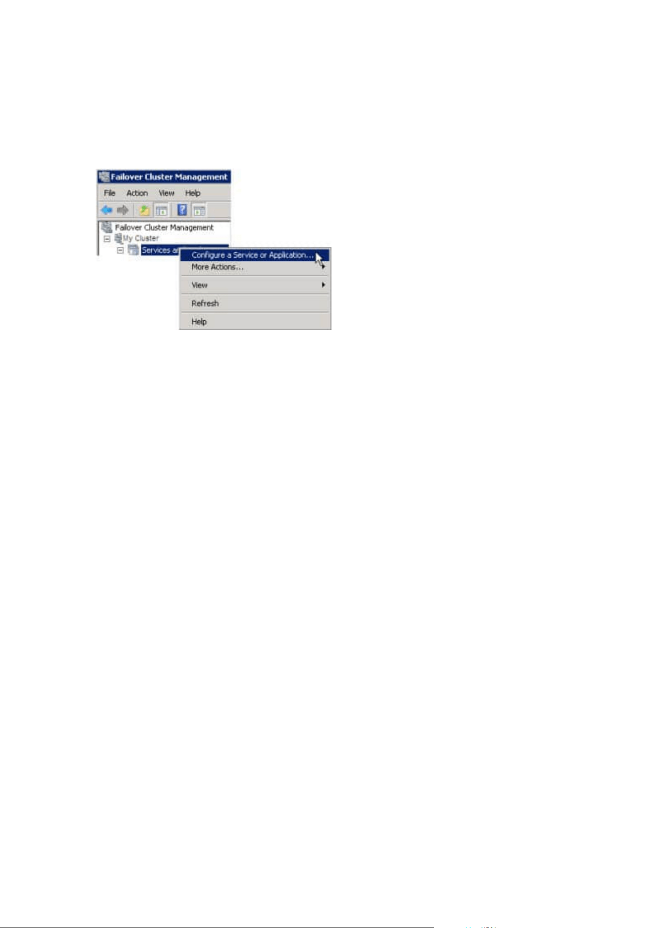
Configure the Management Server service as a generic service in the failover cluster:
1. On the last server on which you have installed the management server, go to Start > Administrative
Tools, open Windows' Failover Cluster Management. In the Failover Cluster Management window,
expand your cluster, right-click Roles, and select Configure Role.
2. In the High Availability Wizard > Before You Begin page, click Next.
3. On the Select Role page, select Generic Service and click Next.
4. On the Select Service page, select the Milestone XProtect Management Server service and click Next.
5. On the Client Access Point page, specify the name (host name of the cluster) that clients will use when
accessing the service. The host name must be different from the name of the cluster. Click Next.
6. On the SelectStorage page, click Next as no storage is required for the service.
7. On the Replicate Registry Settings page, click Next as no registry settings are to be replicated.
8. On the Confirmation page, click Next after you have verified that the cluster service is configured
according to your requirements.
9. On the Configure High Availability page, click Next.
10. On the Summary page, click Finish to complete configuration of the management server as a generic
service in the failover cluster.
Administrator manual | XProtect® VMS 2023 R1
170 | Installation
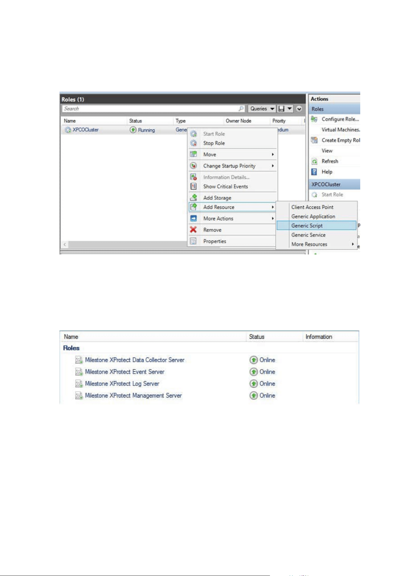
11. Right-click the role you just created and click Add resource >Generic Script. Select Milestone XProtect
Event Server to add the Milestone XProtect Event Server service as a resource to the Milestone
XProtect Management Server Cluster service.
12. Repeat step 11 and add all required services in the cluster, for example the Log Server. The Milestone
XProtect Event Server and the Data Collector server should both be added as services to achieve an
optimal deployment. Additionally, the Milestone XProtect Event Server should be set as a dependent
service of the management server to ensure the event server also will stop when the management
server is stopped.
13. All added services are displayed in the bottom pane of the window.
Administrator manual | XProtect® VMS 2023 R1
171 | Installation

Update the cluster URL:
When doing configuration changes, on the Microsoft Failover Cluster Manager, pause
the control and monitoring of the service so the Server Configurator can make the
changes and start and/or stop the Management Server service. If you change the
failover cluster service startup type to manual, it should not result in any conflicts with
the Server Configurator.
On the Management Server computers:
1. Start the Server Configurator on each of the computers that have a management server installed.
2. Go to the Registration page.
3.
Click the pencil (
) symbol to make management server address editable.
4. Change the management server address to the URL of the cluster, for example http://MyCluster.
5. Click Register.
On computers that have components that use the Management Server (for example, Recording Server, Mobile
Server, Event Server, API Gateway):
1. Start the Server Configurator on each of the computers.
2. Go to the Registration page.
3. Change the management server address to the URL of the cluster, for example http://MyCluster.
4. Click Register.
Use a certificate for an external IDP in a cluster environment
When you install XProtect in a single-server environment, the external IDP configuration data is protected
using Data Protection API (DPAPI). If you set up the management server in a cluster, the external IDP
configuration data must be protected with a certificate to ensure fluent node failover.
For more information about how to generate a certificate, see The Milestone guide about certificates.
You must import the certificate to the personal certificate store and make the certificate trusted on the
computer.
To set up the data protection you must add the thumbprint of the certificate to the Identity Provider
configuration.
Administrator manual | XProtect® VMS 2023 R1
172 | Installation

1. Import the certificate to the personal certificate store and ensure that:
l
the certificate is valid
l
the Identity Provider app pool (IDP) account has permissions to the certificate private key.
For more information about how to verify if the account has permissions to the certificate private key,
see The Milestone guide about certificates.
2. Locate the appsettings.json file in the installation path of the Identity Provider (“[Install
path]\Milestone\XProtect Management Server\IIS\Identity Provider”).
3. Set the certificate thumbprint in the section:
"DataProtectionSettings": {
"ProtectKeysWithCertificate": {
"Thumbprint": ""
}
},
4. Repeat step 3 on all management server nodes.
5. Enforce a node failover to ensure that the certificate setup is correct.
6. Log in again using the management client and apply the external provider configuration. If the
configuration is already applied, you must re-enter the client secret from the external IDP in the
management client.
Troubleshooting errors when an external IDP configuration is protected with a certificate
Invalid certificate/expired certificate
If the configured thumbprint certificate represents a certificate that is not trusted or has expired, the Identity
Provider cannot start. The Identity Provider log (C:\ProgramData\Milestone\Identity Provider\Logs\Idp.log) will
clearly state if the certificate is invalid.
Solution:
Make sure that the certificate is valid and trusted on the computer.
Missing permissions to certificate private keys
The Identity Provider cannot protect data without permissions to the private keys. If the Identity Provider does
not have the permission, the following error message is written to the log file of the Identity Provider
(C:\ProgramData\Milestone\Identity Provider\Logs\Idp.log):
ERROR- An exception occurred while processing the key element ‘<key id=”
[installation specific]” version=”1” />’.
Internal.Cryptography.CryptoThrowHelper+WindowsCryptographicException:
Keyset does not exist
Solution:
Make sure the Identity Provider app pool (IDP) account has permissions to the certificate private keys.
Administrator manual | XProtect® VMS 2023 R1
173 | Installation
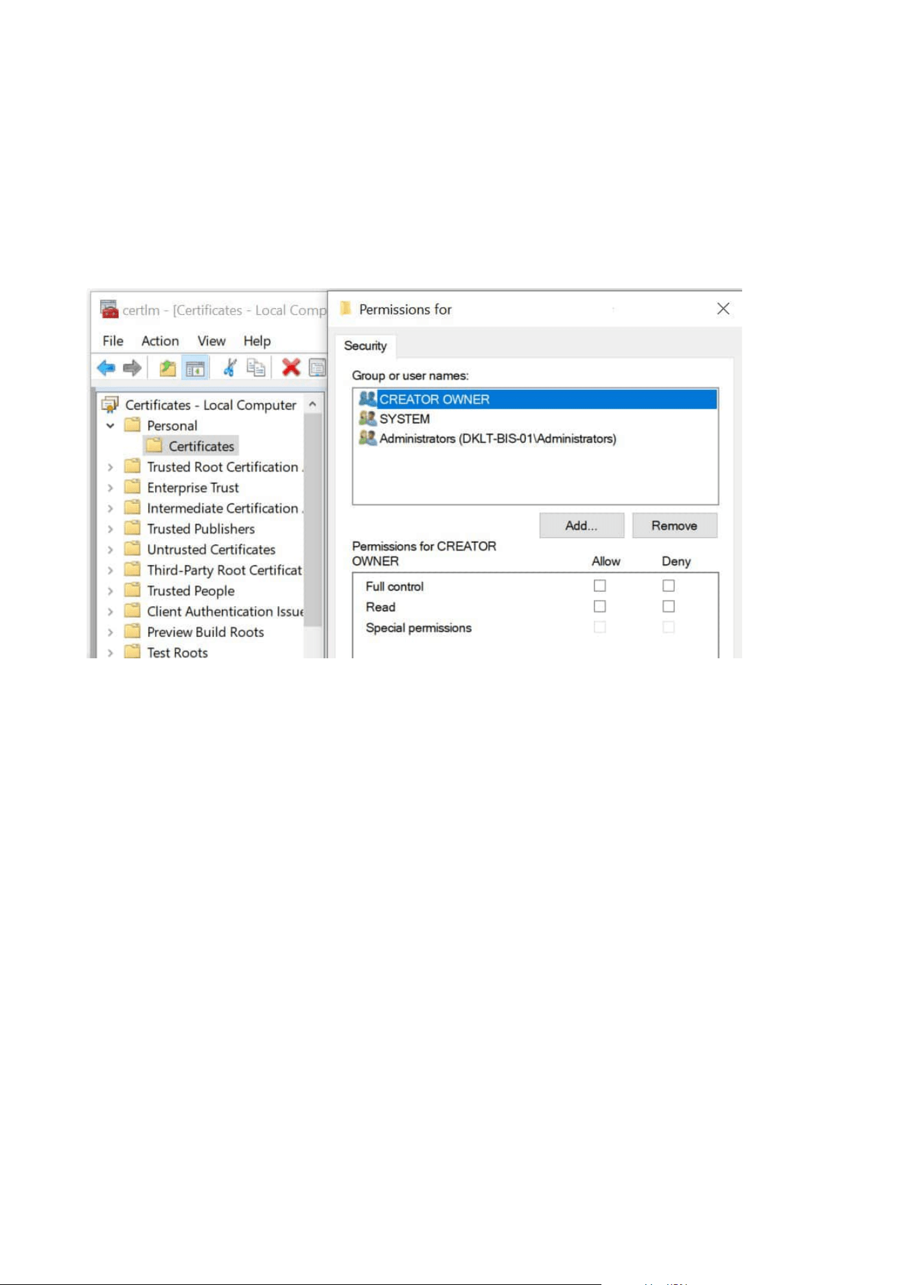
Check permissions to a certificate private key:
1. Select Start on the Windows task bar and open the Manage computer certificates tool (certlm.msc).
2. Navigate to the personal certificate store and find the certificate that is used for the encryption.
3. Right-click on the certificate, and select All Tasks > Manage Private Keys.
4. Under Permissions for, ensure that the Identity Provider app pool (IDP) account has read permissions.
Download Manager/download web page
The management server has a built-in web page. This web page enables administrators and end users to
download and install required XProtect system components from any location, locally or remotely.
Administrator manual | XProtect® VMS 2023 R1
174 | Installation
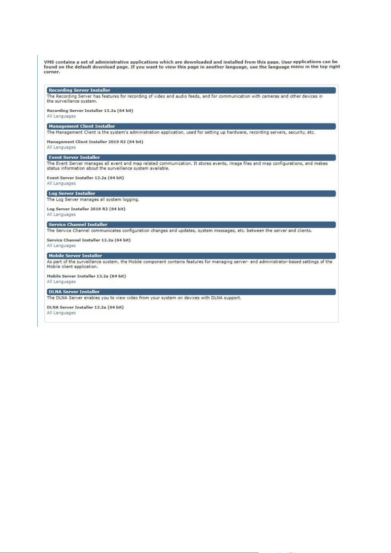
The web page can display two sets of content, both in a language version that by default matches the
language of the system installation:
l
One web page is targeted at administrators, enabling them to download and install key system
components. Most often the web page is automatically loaded at the end of the management server
installation and the default content is displayed. On the management server, you can access the web
page from Windows' Start menu, select Programs > Milestone > Administrative Installation Page.
Otherwise you can enter the URL:
http://[management server address]:[port]/installation/admin/
[management server address] is the IP address or host name of the management server, and [port] is
the port number which you have configured IIS to use on the management server.
Administrator manual | XProtect® VMS 2023 R1
175 | Installation

l
One web page is targeted at end users, providing them access to client applications with default
configuration. On the management server, you can access the web page from Windows' Start menu,
select Programs > Milestone > Public Installation Page. Otherwise you can enter the URL:
http://[management server address]:[port]/installation/
[management server address] is the IP address or host name of the management server, and [port] is
the port number which you have configured IIS to use on the management server.
The two web pages have some default content so you can use them straight away after installation. As
administrator, however, by using the Download Manager, you can customize what should be displayed on the
web pages. You can also move components between the two versions of the web page. To move a component,
right-click it, and select the web page version you want to move the component to.
Even though you can control which components users can download and install in Download Manager, you
cannot use it as a users' permissions management tool. Such permissions are determined by roles defined in
the Management Client.
On the management server, you can access the XProtect Download Manager from Windows' Start menu,
select Programs > Milestone > XProtect Download Manager.
Download Manager's default configuration
The Download Manager has a default configuration. This ensures that your organization's users can access
standard components from the start.
The default configuration provides you a default setup with access to downloading extra or optional
components. Usually you access the web page from the management server computer, but you can also
access the web page from other computers.
Administrator manual | XProtect® VMS 2023 R1
176 | Installation
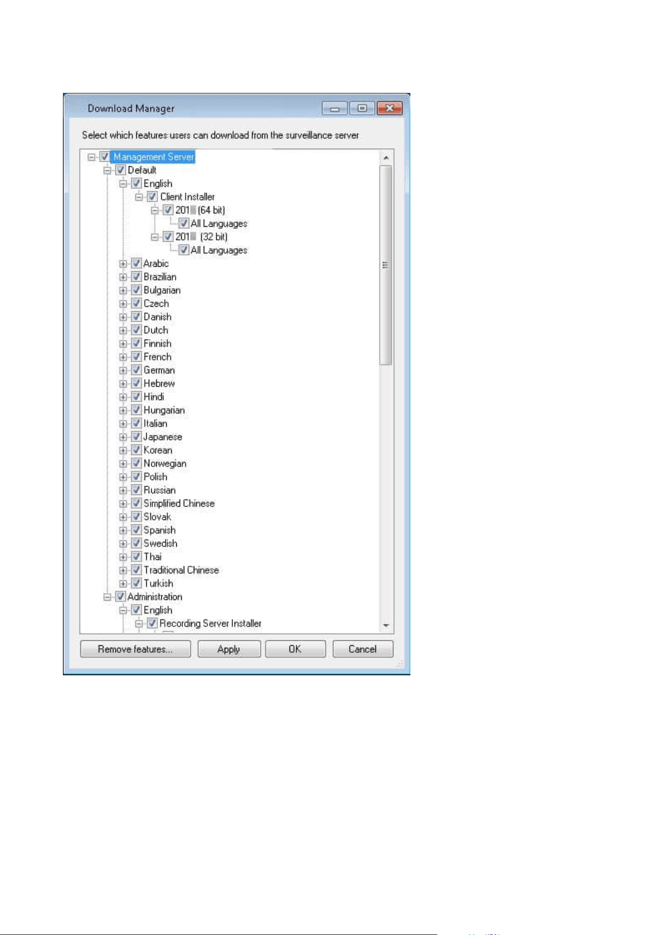
l
The first level: Refers to your XProtect product
l
The second level: Refers to the two targeted versions of the web page. Default refers to the web page
version viewed by end users. Administration refers to the web page version viewed by system
administrators
l
The third level: Refers to the languages in which the web page is available
Administrator manual | XProtect® VMS 2023 R1
177 | Installation

l
The fourth level: Refers to the components which are - or can be made - available to users
l
The fifth level: Refers to particular versions of each component, which are - or can be made - available
to users
l
The sixth level: Refers to the language versions of the components which are - or can be made -
available to users
The fact that only standard components are initially available - and only in the same language version as the
system itself - helps reduce installation time and save space on the server. There is no need to have a
component or language version available on the server if nobody uses it.
You can make more components or languages available as required and you can hide or remove unwanted
components or languages.
Download Manager's standard installers (user)
By default, the following components are available for separate installation from the management server's
download web page targeted at users (controlled by the Download Manager):
l
Recording servers, including failover recording servers. Failover recording servers are initially
downloaded and installed as recording servers, during the installation process you specify that you
want a failover recording server.
l
Management Client
l
XProtect Smart Client
l
Event server, used in connection with map functionality
l
Log server, used for providing the necessary functionality for logging system information
l
XProtect Mobile server
l
More options may be available in your organization.
For installation of device packs, see Device pack installer - must be downloaded on page 180.
Add/publish Download Manager installer components
You must complete two procedures to make non-standard components and new versions available on the
management server's download page.
First you add new and/or non-standard components to the Download Manager. Then you use it to fine-tune
which components should be available in the various language versions of the web page.
If the Download Manager is open, close it before installing new components.
Administrator manual | XProtect® VMS 2023 R1
178 | Installation
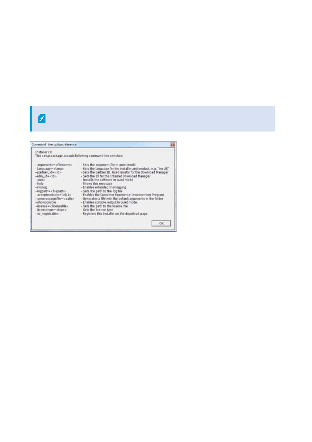
Adding new/non-standard files to the Download Manager:
1. On the computer where you downloaded the component(s), go to Windows' Start, enter a Command
Prompt
2. In the Command Prompt, execute the name of the file (.exe) with:[space]--ss_registration
Example: MilestoneXProtectRecordingServerInstaller_x64.exe --ss_registration
The file is now added to the Download Manager, but not installed on the current computer.
To get an overview of installer commands, in the Command Prompt, enter [space]--help
and the following window appears:
When you have installed new components, they are by default selected in the Download Manager and are
immediately available to users via the web page. You can always show or hide features on the web page by
selecting or clearing check boxes in the Download Manager's tree structure.
You can change the sequence in which components are displayed on the web page. In the Download
Manager's tree structure, drag component items and drop them at the required position.
Hide/remove Download Manager installer components
You have three options:
l
Hide components from the web page by clearing check boxes in the Download Manager's tree
structure. The components are still installed on the management server, and by selecting check boxes
in the Download Manager's tree structure you can quickly make the components available again
Administrator manual | XProtect® VMS 2023 R1
179 | Installation
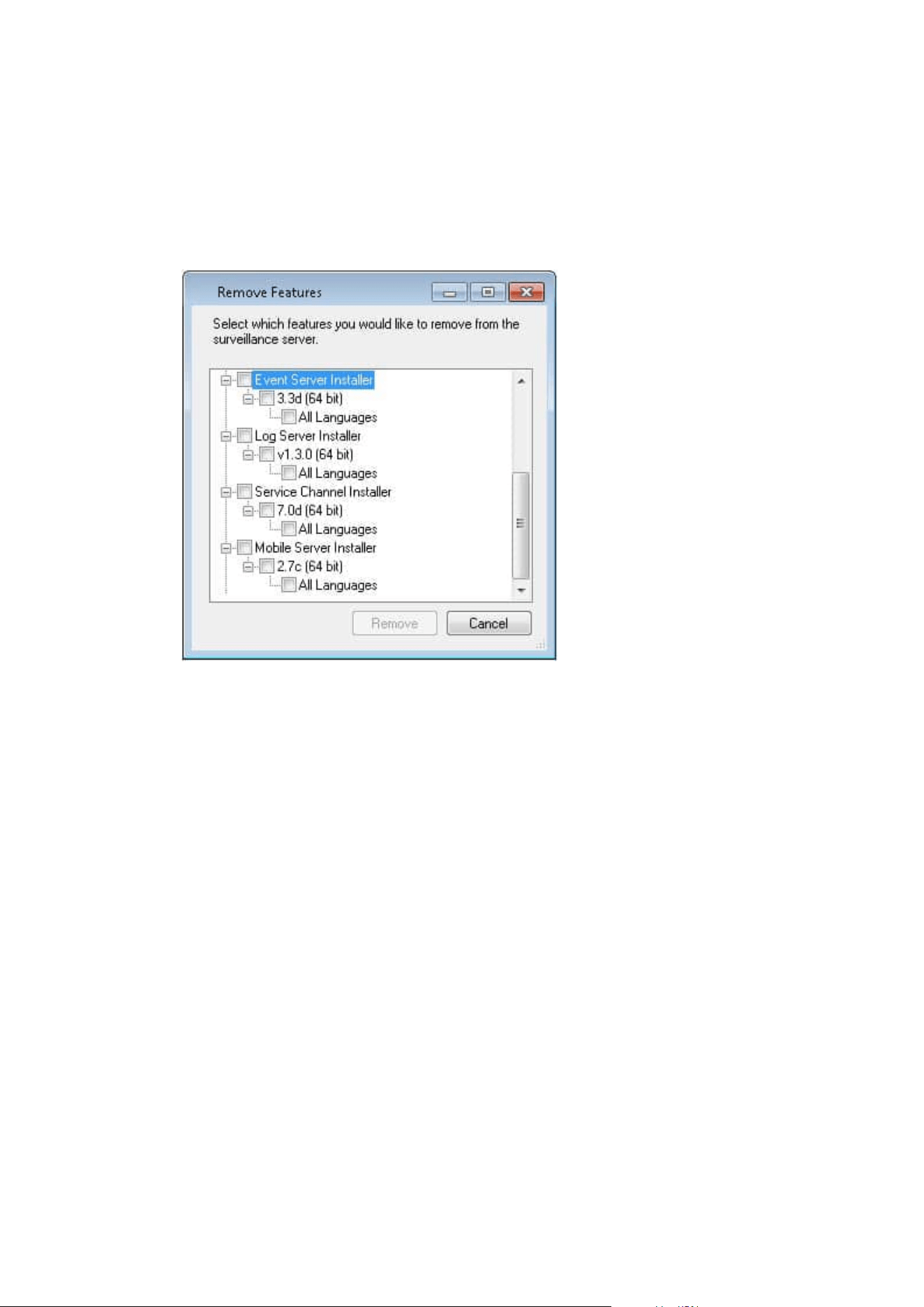
l
Remove the installation of components on the management server. The components disappear from
the Download Manager, but installation files for the components are kept at C:\Program Files
(x86)\Milestone\XProtect Download Manager, so you can re-install them later if required
1. In the Download Manager, click Remove features.
2. In the Remove Features window, select the feature(s) you want to remove.
3. Click OK and Yes.
l
Remove installation files for non-required features from the management server. This can help save
disk space on the server if you know that your organization is not going to use certain features
Device pack installer - must be downloaded
The device pack (containing device drivers) included in your original installation is not included on the
Download Manager. So, if you need to reinstall the device pack or make the device pack installer available, you
must first add or publish the latest device pack installer to the Download Manager:
1. Get the latest regular device pack from the download page on the Milestone website
(https://www.milestonesys.com/downloads/).
2. On the same page, you can download the legacy device pack with older drivers. To check if your
cameras use drivers from the legacy device pack, go to this website
(https://www.milestonesys.com/community/business-partner-tools/device-packs/).
3. Add/publish it to the Download Manager by calling it with the --ss_registration command.
Administrator manual | XProtect® VMS 2023 R1
180 | Installation

If you do not have a network connection, you can reinstall the entire recording server from the Download
Manager. The installation files for the recording server is placed locally on your computer and in this way, you
automatically get a reinstall of the device pack.
Installation log files and troubleshooting
During an installation, upgrade or uninstallation, log entries are written to various installation log files: To the
main installation log file installer.log and to the log files belonging to the different system components you are
installing. All log entries have a time stamp and the most recent log entries are at the end of the log files.
You can find all installation log files in the C:\ProgramData\Milestone\Installer\ folder. Log files that are named
*I.log or *I[integer].log are log files about new installations or upgrades while log files named *U.log or *U
[integer].log are about uninstallations. If you have bought a server with an already installed XProtect system
through a Milestone partner, there might not be any installation log files.
The log files contain information about the command-line parameters and command-line options and their
values used during an installation, upgrade or uninstallation. To find the used command-line parameters in the
log files, search for Command Line: or Parameter ' depending on the log file.
For troubleshooting, the main installation log file installer.log is the first place to look. If there were any
exceptions, errors, or warnings during the installation, these have been logged. Try to search for exception,
error, or warning. "Exit code: 0" means a successful installation and "Exit code: 1" the opposite. Your findings
in the log files may enable you to find a solution on Milestone Knowledge Base. If not, contact your Milestone
partner and share the relevant installation log files.
Administrator manual | XProtect® VMS 2023 R1
181 | Installation
Configuration
Initial configuration tasks list
The checklist below lists the initial tasks for configuring your system. Some of them, you may already have
completed during installation.
A completed checklist does not in itself guarantee that the system matches the exact requirements of your
organization. To make the system match the needs of your organization, Milestone recommends that you
monitor and adjust the system continuously.
For example, it is a good idea to test and adjust the motion detection sensitivity settings of individual cameras
under different physical conditions, including day/night and windy calm weather, once the system is running.
The setup of rules, which determine most of the actions your system performs, including when to record video,
is another example of configuration that you can change according to your organization's needs.
Step Description
You have finished the initial installation of your system.
See Install a new XProtect system on page 140.
Change the trial SLC to a permanent SLC (if required).
See Change the Software License Code on page 117.
Log in to the Management Client.
See Logging in (explained) on page 28.
Verify that each recording server's storage settings meet your needs.
See Storage and archiving (explained) on page 54.
Verify that each recording server's archiving settings meet your needs.
See Storage and Recording Settings properties on page 398.
Detect the hardware, cameras or video encoders to add to each recording server.
See Add hardware on page 203.
Configure each recording server's individual cameras.
Administrator manual | XProtect® VMS 2023 R1
182 | Configuration
Step Description
See Cameras (Devices node) on page 416.
Enable storage and archiving for individual cameras or for a group of cameras. This is done
from the individual cameras or from the device group.
See Attach a device or group of devices to a storage on page 189.
Enable and configure devices.
See Devices (Devices node) on page 413.
Rules determine the system's behavior to a large extent. You create rules to define when
cameras should record, when pan-tilt-zoom (PTZ) cameras should patrol, and when
notifications should be sent, for example.
Create rules.
See Rules and events (explained) on page 74.
Add roles to the system.
See Roles and permissions of a role (explained) on page 66.
Add users or groups of users to each of the roles.
See Assign/remove users and groups to/from roles on page 273.
Activate licenses.
See Activate licenses online on page 116 or Activate licenses offline on page 116.
For more information about how to configure the system in the Site Navigation pane, see Site Navigation
pane on page 364.
Recording servers
Change or verify the basic configuration of a recording server
If your Management Client does not list all the recording servers you have installed, the most likely reason is
that you have configured the setup parameters (for example, the IP address or host name of the management
server) incorrectly during installation.
Administrator manual | XProtect® VMS 2023 R1
183 | Configuration
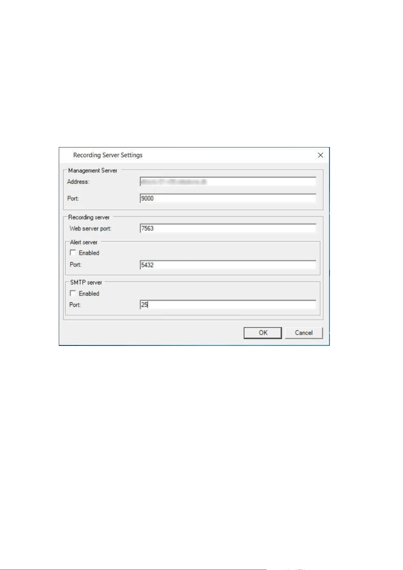
You do not need to re-install recording servers to specify the parameters of the management servers, but you
can change/verify its basic configuration:
1. On the computer that runs the recording server, right-click the Recording Server icon in the notification
area.
2. Select Stop Recording Server service.
3. Right-click the Recording Server icon again and select Change Settings.
The Recording Server Settings window appears.
Administrator manual | XProtect® VMS 2023 R1
184 | Configuration
4. Verify or change, for example, the following settings:
l
Management server: Address: Specify the IP address or host name of the management server
to which the recording server should be connected.
l
Management server: Port: Specify the port number to be used when communicating with the
management server. You can change this if required, but the port number must always match
the port number set up on the management server. See Ports used by the system on page 91.
l
Recording server: Web server port: Specify the port number to be used when communicating
with the recording server's web server. See Ports used by the system on page 91.
l
Recording server: Alert server port: Enable and specify the port number to be used when
communicating with the recording server's alert server, which listens for event messages from
devices. See Ports used by the system on page 91.
l
SMTP server: Port: Enable and specify the port number to be used when communicating with
the recording server's Simple Mail Transfer Protocol (SMTP) service. See Ports used by the
system on page 91.
5. Click OK.
6. To start the Recording Server service again, right-click the Recording Server icon, and select Start
Recording Server service.
Stopping the Recording Server service means that you cannot record and view live video
while you verify/change the recording server's basic configuration.
Register a recording server
When you install a recording server, it is automatically registered in most cases. But you need to do the
registration manually if:
l
You have replaced the recording server
l
The recording server was installed offline and then added to the management server afterward
l
Your management server does not use the default ports. The port numbers depend on the encryption
configuration. For more information, see Ports used by the system on page 91
l
An automatic registration has failed, for example after changing the management server address,
changing the name of the computer with the recording server, or after enabling or disabling server
communication encryption settings. For more information about changes to the management server
address, see Changing the host name of the management server computer.
When you register a recording server, you configure it to connect to your management server. The part of the
management server that handles registration is the Authorization Server service.
Administrator manual | XProtect® VMS 2023 R1
185 | Configuration
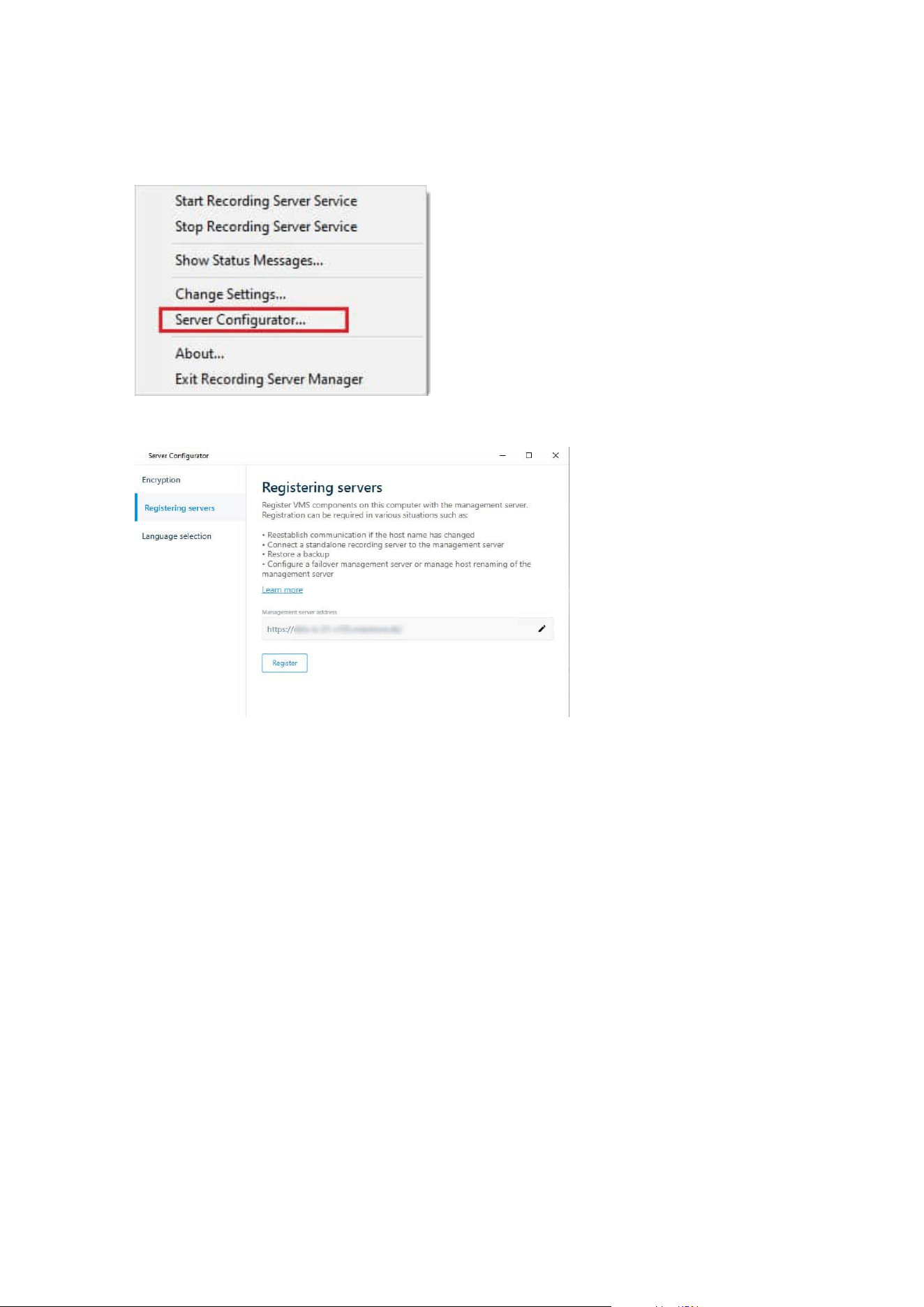
1. Open the Server Configurator from either the Windows startup menu or from the recording server tray
icon.
2. In the Server Configurator, select Registering servers.
3. Verify the address of the management server and the scheme (http or https) that you want the servers
on the computer to connect to and click Register.
A confirmation appears, stating that registration on the management server has succeeded.
See also Replace a recording server on page 323.
View encryption status to clients
To verify if your recording server encrypt connections:
Administrator manual | XProtect® VMS 2023 R1
186 | Configuration
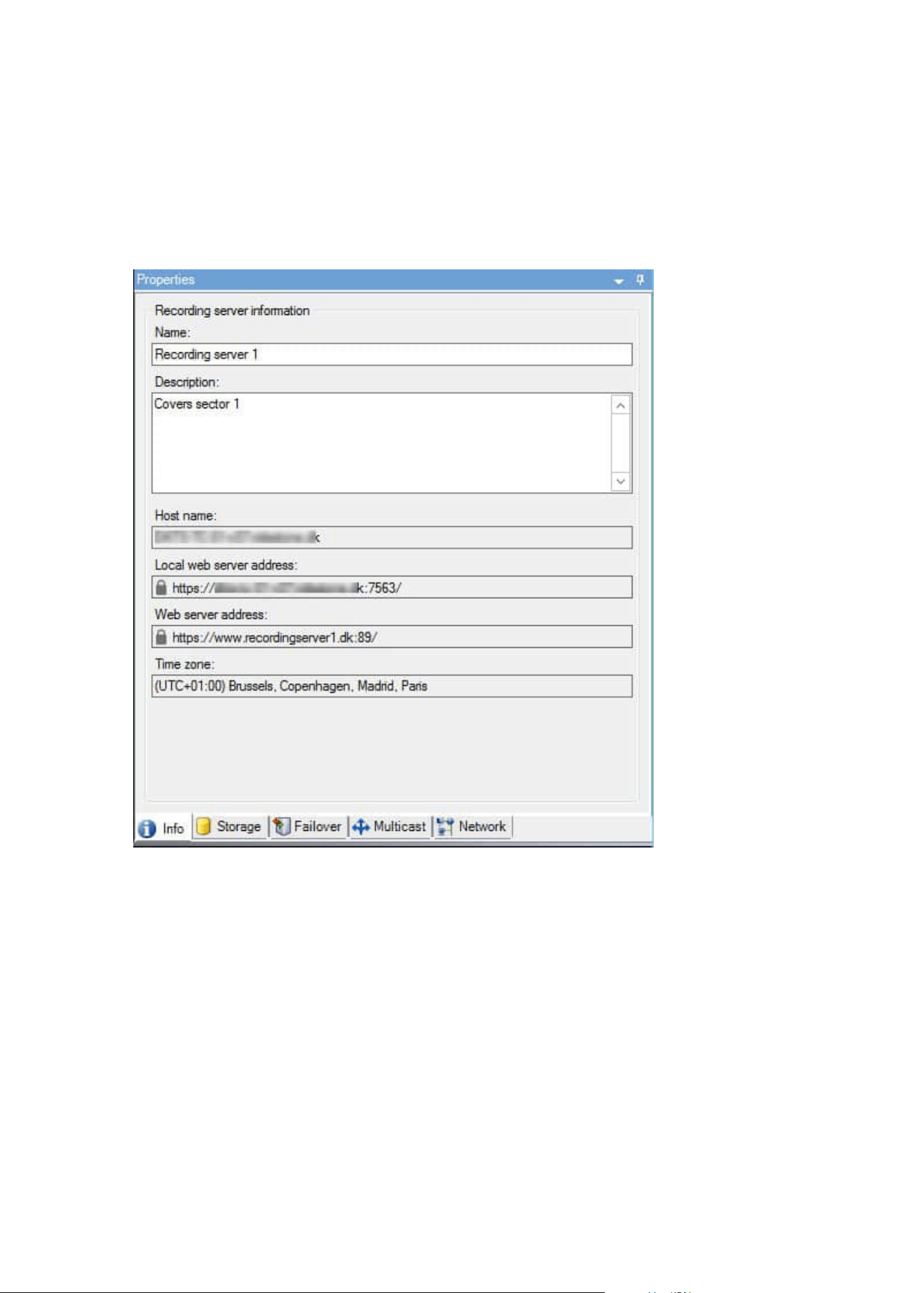
1. Open the Management Client.
2. In the Site Navigation pane, select Servers > Recording Servers. This opens a list of recording servers.
3. In the Overview pane, select the relevant recording server and go to the Info tab.
If encryption is enabled to clients and servers that retrieve data streams from the recording server, a
padlock icon appears in front of the local web server address and the optional web server address.
Specify behavior when recording storage is unavailable
By default, the recording server keeps running if a recording storage becomes unavailable. If your system is
configured with failover recording servers, you can specify the recording server to stop running, to make the
failover servers take over:
Administrator manual | XProtect® VMS 2023 R1
187 | Configuration
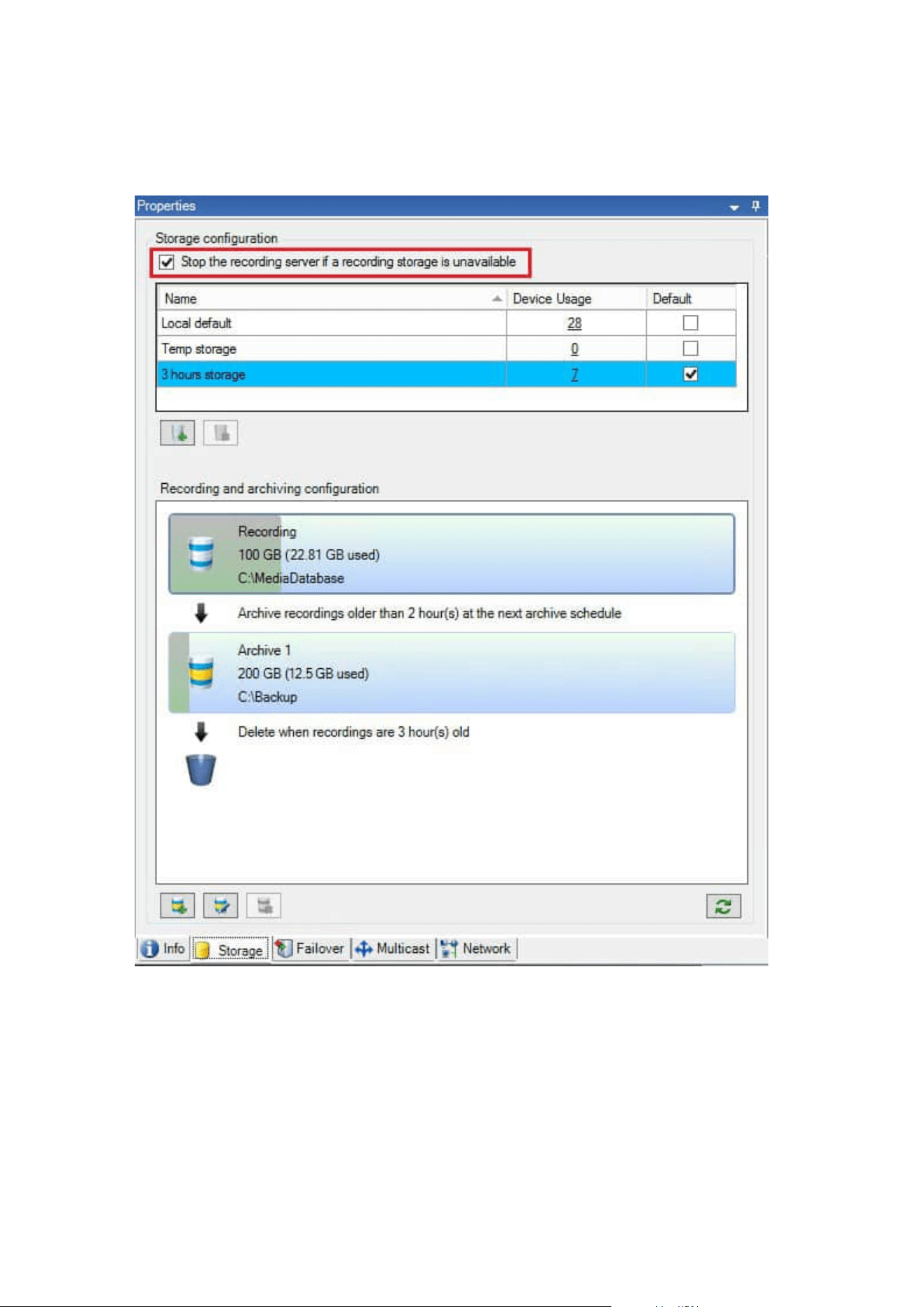
1. On the relevant recording server, go to the Storage tab.
2. Select the Stop the recording server if a recording storage is unavailable option.
Add a new storage
When you add a new storage, you always create one recording storage with a predefined recording database
named Recording. You cannot rename the database. Apart from the recording storage, a storage can contain
a number of archives.
Administrator manual | XProtect® VMS 2023 R1
188 | Configuration

1.
To add an extra storage to a selected recording server, click the
button located below the Storage
configuration list. This opens the Storage and Recording Settings dialog box.
2. Specify the relevant settings (see
Storage and Recording Settings properties on page 398).
3. Click OK.
If needed, you are now ready to create archive(s) within your new storage.
Create an archive within a storage
A storage has no default archive, but you can create archives as needed.
1. Select the relevant storage in the Recording and archiving configuration list.
2.
Click the
button below the Recording and archiving configuration list.
3. In the Archive Settings dialog box, specify the required settings (see
Archive Settings properties on
page 400).
4. Click OK.
Attach a device or group of devices to a storage
Once a storage is configured for a recording server, you can enable it for individual devices such as cameras,
microphones or speakers or a group of devices. You can also select which of a recording server's storage areas
you want to use for the individual device or the group.
1. Expand Devices and select either Cameras, Microphones or Speakers as required.
2. Select the device or a device group.
3. Select the Record tab.
4. In the Storage area, select Select.
5. In the dialog box that appears, select the database that should store the recordings of the device and
then click OK.
6. In the toolbar, click Save.
When you click the device usage number for the storage area on the Storage tab of the recording server, the
device is visible in the message report that appears.
Disabled devices
Disabled devices are by default not displayed in the Overview pane.
To display all disabled devices, in the top of the Overview pane, click Filter to open the Filter tab and select
Show disabled devices.
To hide disabled devices again, clear Show disabled devices.
Administrator manual | XProtect® VMS 2023 R1
189 | Configuration
Edit settings for a selected storage or archive
1. To edit a storage, select its recording database in the Recording and archiving configuration list. To
edit an archive, select the archive database.
2.
Click the Edit Recording Storage button
located below the Recording and archiving
configuration list.
3. Either edit a recording database or edit an archive.
If you change the maximum size of a database, the system auto-archives recordings that
exceed the new limit. It auto-archives the recordings to the next archive or deletes them
depending on archiving settings.
Enable digital signing for export
Available functionality depends on the system you are using. See the complete feature
list, which is available on the product overview page on the Milestone website
(https://www.milestonesys.com/solutions/platform/product-index/).
You can enable digital signing for recorded video, so that client users can verify that the recorded video has
not been tampered with since it was recorded. Verifying the authenticity of the video is something that the
user does in XProtect Smart Client – Player after the video has been exported.
Signing must also be activated in XProtect Smart Client > Exports tab > Export settings >
XProtect format > Include digital signature. Otherwise, the Verify Signatures button in
XProtect Smart Client – Player is not displayed.
1. In the Site Navigation pane, expand the Servers node.
2. Click Recording Servers.
3. In the overview pane, click the recording server you want to enable signing for.
Administrator manual | XProtect® VMS 2023 R1
190 | Configuration
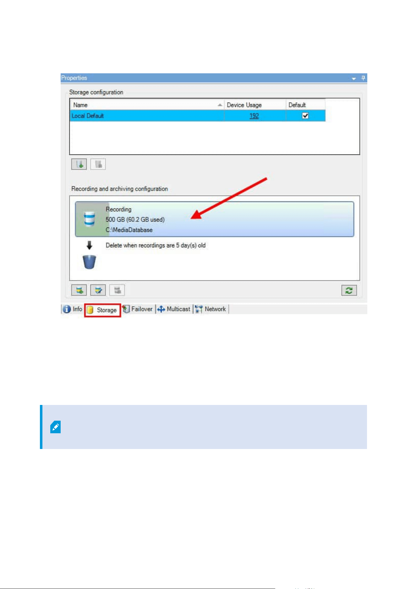
4. At the bottom of the Properties pane, click the Storage tab.
5. In the Recording and archiving configuration section, double-click the horizontal bar that represents
the recording database. The Storage and Recording Settings window appears.
6. Select the Signing check box.
7. Click OK.
Encrypt your recordings
Available functionality depends on the system you are using. See the complete feature
list, which is available on the product overview page on the Milestone website
(https://www.milestonesys.com/solutions/platform/product-index/).
You can secure your recordings by enabling encryption on your recording servers' storage and archives. You
can choose between light and strong encryption. When you enable encryption, you must also specify a related
password.
Administrator manual | XProtect® VMS 2023 R1
191 | Configuration

Enabling or changing encryption settings or password can potentially be time
consuming, depending on the size of the database and performance of the drive. You
can follow the progress under Current Tasks.
Do not stop the recording server while this task is ongoing.
Administrator manual | XProtect® VMS 2023 R1
192 | Configuration
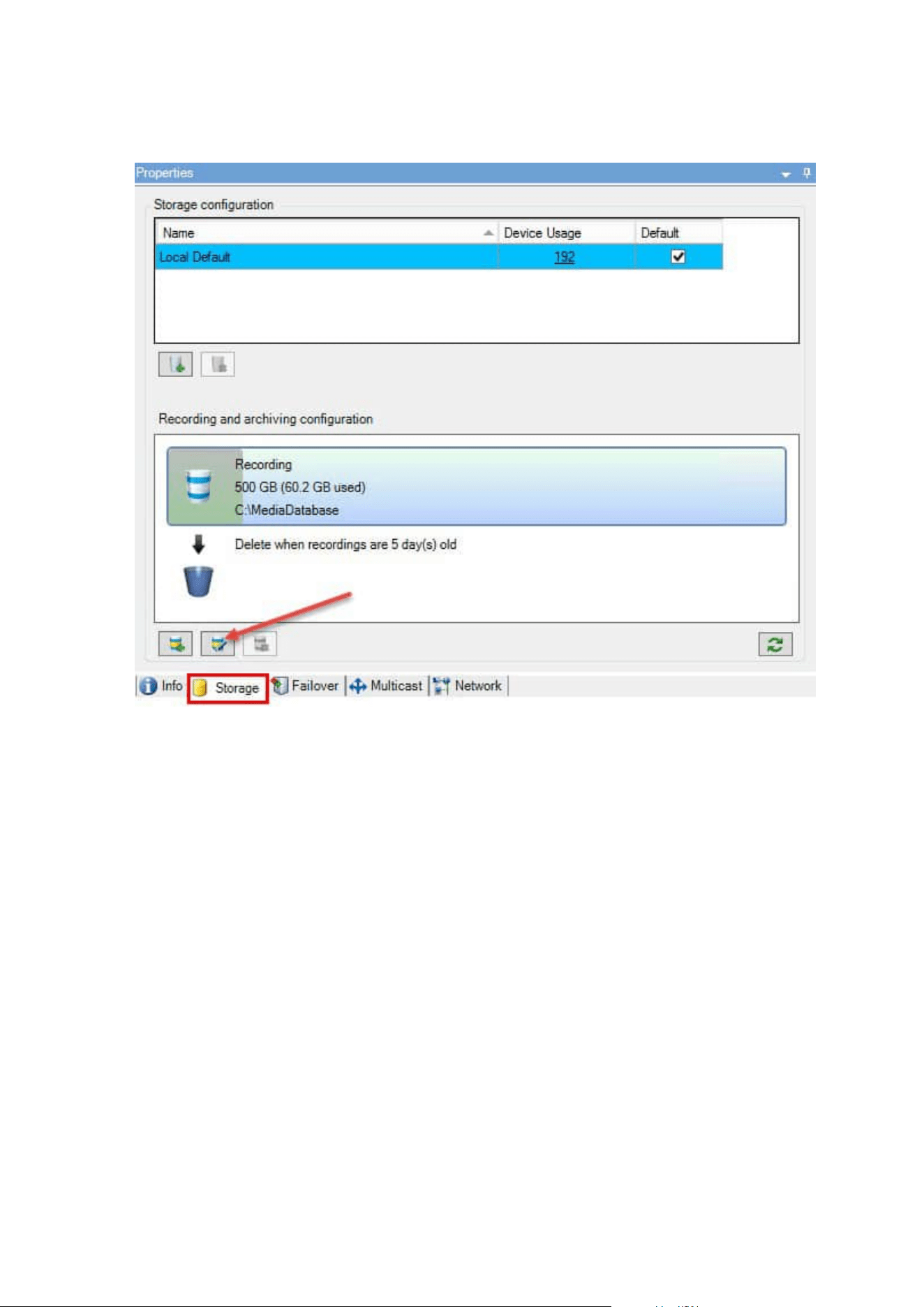
1. Click the Edit Recording Storage button below the Recording and archiving configuration list.
Administrator manual | XProtect® VMS 2023 R1
193 | Configuration
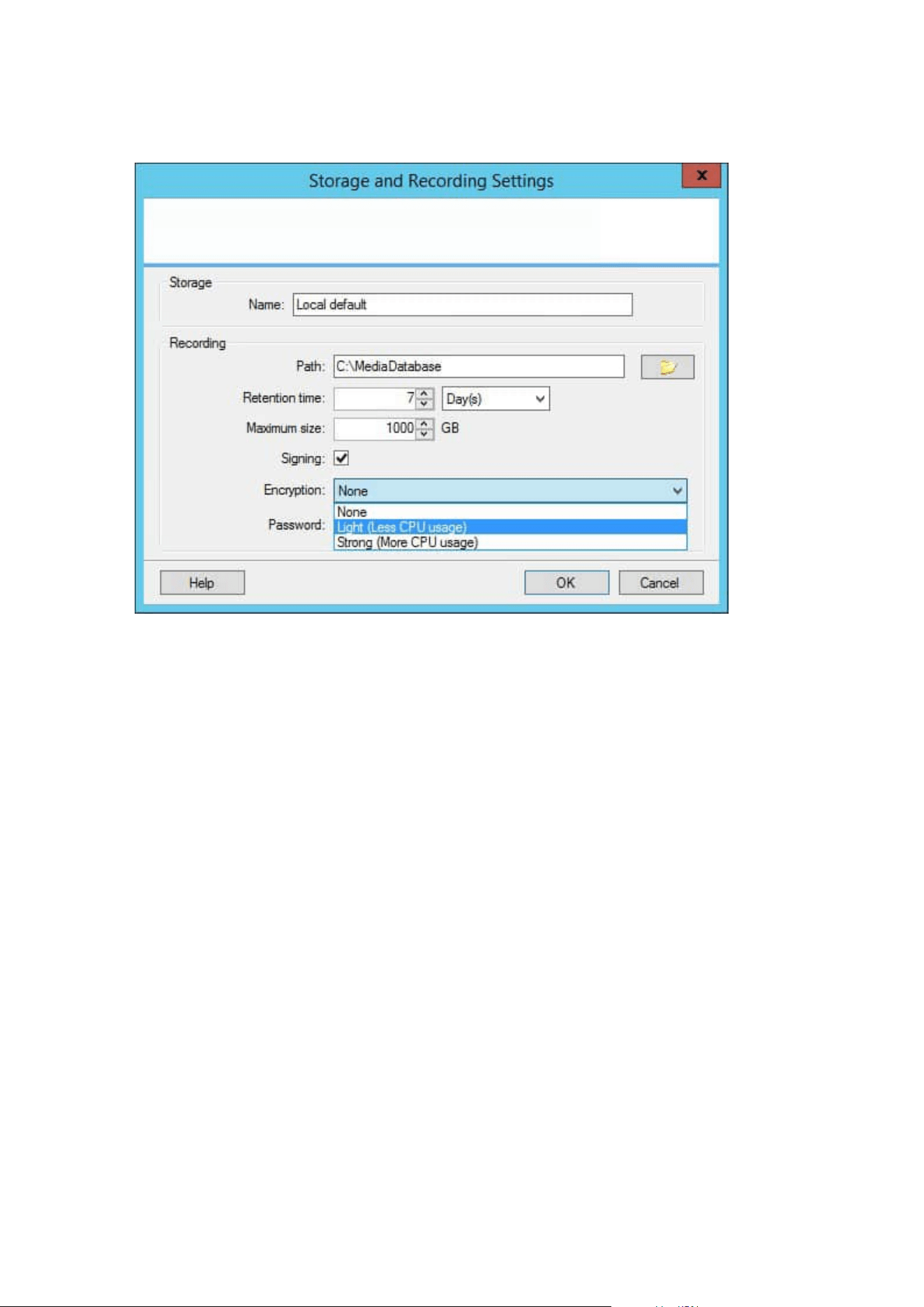
2. In the dialog box that appears, specify encryption level.
3. You are automatically directed to Set Password dialog box. Enter password and click OK.
Back up archived recordings
Many organizations want to back up their recordings by using tape drives or similar. Exactly how you do this is
highly individual and depends on the backup media used in your organization. However, the following is worth
bearing in mind:
Back up archives rather than camera databases
Always create backups based on the content of archives, not based on individual camera databases. If you
create backups based on the content of individual camera databases, you may cause sharing violations or
other malfunctions.
When scheduling a backup, make sure the backup job does not overlap with your specified archiving times. To
view each recording server's archiving schedule in each of a recording server's storage areas, see the Storage tab.
Know your archive structure so that you can target backups
When you archive recordings, you store them in a certain sub-directory structure within the archive.
During all regular use of your system, the sub-directory structure is completely transparent to the system's
users when they browse recordings with XProtect Smart Client. This is true both with archived and non-
archived recordings. It is relevant to know the sub-directory structure (see Archive structure (explained) on
page 59 if you want to back up your archived recordings (see Backing up and restoring system configuration
on page 313).
Administrator manual | XProtect® VMS 2023 R1
194 | Configuration
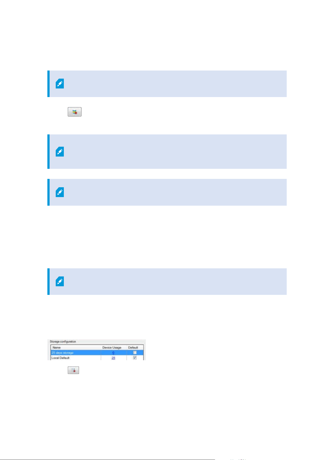
Delete an archive from a storage
1. Select the archive from the Recording and archiving configuration list.
It is only possible to delete the last archive in the list. The archive does not have
to be empty.
2.
Click the
button located below the Recording and archiving configuration list.
3. Click Yes.
For unavailable archives, for example offline archives, it is not possible to verify if
the archive contains media with evidence locks but the archive can be deleted
after user confirmation.
Available archives (online archives) that contain media with evidence locks cannot
be deleted.
Delete a storage
You cannot delete the default storage or storages that devices use as the recording storage for live recordings.
This means that you may need to move devices (see Move hardware on page 324) and any not yet archived
recordings to another storage before you delete the storage.
1. To see the list of devices that use this storage, click the device usage number.
If the storage has data from devices that have been moved to another recording
server, a warning appears. Click the link to see the list of devices.
2. Follow the steps in Move non-archived recordings from one storage to another on page 196.
3. Continue until you have moved all devices.
4. Select the storage that you want to delete.
5.
Click the
button located below the Storage configuration list.
6. Click Yes.
Administrator manual | XProtect® VMS 2023 R1
195 | Configuration

Move non-archived recordings from one storage to another
You move recordings from one live recording database to another from the Record tab of the device.
1. Select the device type. In the Overview pane, select the device.
2. Click the Record tab. In the upper part of the Storage area, click Select.
3. In the Select Storage dialog box, select the database.
4. Click OK.
5. In the Recordings Action dialog box, select if you want to remove already existing - but non-archived -
recordings to the new storage or if you want to delete them.
6. Click OK.
Assign failover recording servers
On the Failover tab of a recording server, you can choose between three types of failover setups:
l
No failover setup
l
A primary/secondary failover setup (cold standby)
l
A hot standby setup
If you select b and c, you must select the specific server/groups. With b, you can also select a secondary
failover group. If the recording server becomes unavailable, a failover recording server from the primary
failover group takes over. If you have also selected a secondary failover group, a failover recording server from
the secondary group takes over in case all failover recording servers in the primary failover group are busy. In
this way, you only risk not having a failover solution in the rare case when all failover recording servers in the
primary, as well as in the secondary, failover group are busy.
1. In the Site Navigation pane, select Servers > Recording Servers. This opens a list of recording servers.
2. In the Overview pane, select the wanted recording server, go to the Failover tab.
3. To choose failover setup type, select between:
l
None
l
Primary failover server group/Secondary failover sever group
l
Hot standby server
You cannot select the same failover group as both primary and secondary failover group nor select
regular failover servers already part of a failover group as hot standby servers.
4. Next, click Advanced failover settings. This opens the Advanced Failover Settings window, listing all
devices attached to the selected recording server. If you selected None, the advanced failover settings
are also available. The system keeps any selections for later failover setups.
Administrator manual | XProtect® VMS 2023 R1
196 | Configuration
5. To specify the level of failover support, select Full Support, Live Only or Disabled for each device in the
list. Click OK.
6. In the Failover service communication port (TCP) field, edit the port number if needed.
If you enable failover support and the recording server is configured to keep running if a
recording storage is unavailable, the failover recording server will not take over. To
make the failover support work, you must select the Stop the recording server if a
recording storage is unavailable option on the Storage tab.
Enable multicasting for the recording server
In regular network communication, each data packet is sent from a single sender to a single recipient - a
process known as unicasting. But with multicasting you can send a single data packet (from a server) to
multiple recipients (clients) within a group. Multicasting can help save bandwidth.
l
When you use unicasting, the source must transmit one data stream for each recipient
l
When you use multicasting, only a single data stream is required on each network segment
Multicasting as described here is not streaming of video from camera to servers, but from servers to clients.
With multicasting, you work with a defined group of recipients, based on options such as IP address ranges, the
ability to enable/disable multicast for individual cameras, the ability to define largest acceptable data packet size
(MTU), the maximum number of routers a data packet must be forwarded between (TTL), and so on.
Multicast streams are not encrypted, even if the recording server uses encryption.
Multicasting should not be confused with broadcasting, which sends data to everyone connected to the
network, even if the data is perhaps not relevant for everyone:
Name Description
Unicasting Sends data from a single source to a single recipient.
Multicasting Sends data from a single source to multiple recipients within a clearly defined group.
Broadcasting
Sends data from a single source to everyone on a network. Broadcasting can
therefore significantly slow down network communication.
Administrator manual | XProtect® VMS 2023 R1
197 | Configuration
To use multicasting, your network infrastructure must support the IP multicasting standard IGMP (Internet
Group Management Protocol).
l
On the Multicast tab, select the Multicast check box
If the entire IP address range for multicast is already in use on one or more recording servers, you first release
some multicast IP addresses before you can enable multicasting on additional recording servers.
Multicast streams are not encrypted, even if the recording server uses encryption.
Enable multicasting for individual cameras
Multicasting only works when you enable it for the relevant cameras:
1. Select the recording server and select the required camera in the Overview pane.
2. On the Client tab, select the Live multicast check box. Repeat for all relevant cameras.
Multicast streams are not encrypted, even if the recording server uses encryption.
Define public address and port
If you need to access the VMS with XProtect Smart Client over a public or untrusted
network, Milestone recommends that you use a secure connection through VPN. This
helps ensure that communication between XProtect Smart Client and the VMS server is
protected.
You define a recording server's public IP address on the Network tab.
Why use a public address?
Clients may connect from the local network as well as from the Internet, and in both cases the surveillance
system must provide suitable addresses so the clients can get access to live and recorded video from the
recording servers:
l
When clients connect locally, the surveillance system should reply with local addresses and port
numbers
l
When clients connect from the internet, the surveillance system should reply with the recording server's
public address. This is the address of the firewall or NAT (Network Address Translation) router, and
often also a different port number. The address and the port can then be forwarded to the server's local
address and port.
Administrator manual | XProtect® VMS 2023 R1
198 | Configuration

1. To enable public access, select the Enable public access check box.
2. Define the recording server's public address. Enter the address of the firewall or NAT router so clients
that access the surveillance system from the Internet can connect to the recording servers.
3. Specify a public port number. It is always a good idea that port numbers used on the firewall or NAT
router are different from the ones used locally.
If you use public access, configure the firewall or NAT router so requests sent to the
public address and port are forwarded to the local address and port of relevant
recording servers.
Assign local IP ranges
You define a list of local IP ranges which the surveillance system should recognize as coming from a local
network:
l
On the Network tab, click Configure
Filter the device tree
The device tree in the Overview pane can become very large if you have many registered devices. You can
filter the device tree to easier locate the devices you want to work with.
By providing filter terms that are unique to a few specific devices, you can effectively only display these specific
devices.
Filter the device tree
l
In the top of the Overview pane, click Filter to open the Filter tab.
l
In the Type here to filter devices field, enter one or more filter criteria and click Apply filter to filter the
device list.
Filter criteria characteristics
The filter criteria are applied to the device name, device short name, hardware address (IP), device ID, and
hardware ID field values.
Partial filter matches are not displayed when filtering hardware ID and device ID field values. As a result, you
must define the complete and exact identification number when filtering by hardware ID or device ID.
Partial filter matches are displayed for device name, device short name, and hardware address field values, so
the filter term “camer” will display all devices that contain the word “camera” in the device name.
Filter criteria are not case sensitive, using "camera" or "Camera" as filter criteria will yield
the same results.
Administrator manual | XProtect® VMS 2023 R1
199 | Configuration
Specifying multiple filter criteria
You can specify multiple filter criteria and thereby further narrow your filtering of the device tree. When the
filter is applied, all defined filter criteria are considered to be co-joined with an AND, meaning they are
cumulative.
For example, if you have entered two filter criteria: “Camera” and “Warehouse”, the list will display all devices
that contain the words “Camera” and “Warehouse” in the device name but will not display devices that contain
the words “Camera” and “Parking Lot” in the device name nor will devices that only contain the word "Camera"
in the device name be displayed.
Remove each individual filter criteria from the filter field to broaden your filter if you have specified a filter that
is too restrictive. The filter is automatically applied to the device tree when removing filter criteria.
Resetting the filter
If you remove all filter criteria from the filter field, the Overview pane is reset and will display all devices once
again.
You can also press F5 to reset the filter and clear the Show disabled devices check box.
Disabled devices
Disabled devices are by default not displayed in the Overview pane.
To display all disabled devices, in the top of the Overview pane, click Filter to open the Filter tab and select
Show disabled devices.
To hide disabled devices again, clear Show disabled devices.
Failover servers
Set up and enable failover recording servers
If you have disabled the failover recording server, you must enable it before it can take
over from the standard recording servers.
Do the following to enable a failover recording server and edit its basic properties:
1. In the Site Navigation pane, select Servers > Failover Servers. This opens a list of installed failover
recording servers and failover groups.
2. In the Overview pane, select the required failover recording server.
3. Right-click and select Enabled. The failover recording server is now enabled.
4. To edit failover recording server properties, go to the Info tab.
Administrator manual | XProtect® VMS 2023 R1
200 | Configuration

5. When done, go to the Network tab. Here you can define the failover recording server's public IP
address and more. This is relevant if you use NAT (Network Address Translation) and port forwarding.
See the standard recording server's Network tab for more information.
6. In the Site Navigation pane, select Servers > Recording Servers. Select the recording server that you
want failover support for and assign failover recording servers (see Failover tab (recording server) on
page 401).
To see the status of a failover recording server, hold your mouse over the Failover Recording Server Manager
tray icon in the notification area. A tooltip appears containing the text entered in the Description field of the
failover recording server. This may help you determine which recording server the failover recording server is
configured to take over from.
The failover recording server pings the management server on a regular basis to verify
that it is online and able to request and receive the configuration of the standard
recording servers when needed. If you block the pinging, the failover recording server is
not able to take over from the standard recording servers.
Group failover recording servers for cold standby
1. Select Servers > Failover Servers. This opens a list of installed failover recording servers and failover
groups.
2. In the Overview pane, right-click the top-node Failover Groups and select Add Group.
3. Specify a name (in this example Failover Group 1) for and a description (optional) of your new group.
Click OK.
4. Right-click the group (Failover Group 1) you just created. Select Edit Group Members. This opens the
Select Group Members window.
5. Drag and drop or use the buttons to move the selected failover recording server(s) from the left side to
the right side. Click OK. The selected failover recording server(s) now belongs to the group (Failover
Group 1) you just created.
6. Go to the Sequence tab. Click Up and Down to set the internal sequence of the regular failover
recordings servers in the group.
View encryption status on a failover recording server
To verify if your failover recording server uses encryption, do the following:
1. In the Site Navigation pane, select Servers > Failover Servers. This opens a list of failover recording
servers.
2. In the Overview pane, select the relevant recording server and go to the Info tab.
If encryption is enabled to clients and servers that retrieve data streams from the recording server, a
Administrator manual | XProtect® VMS 2023 R1
201 | Configuration
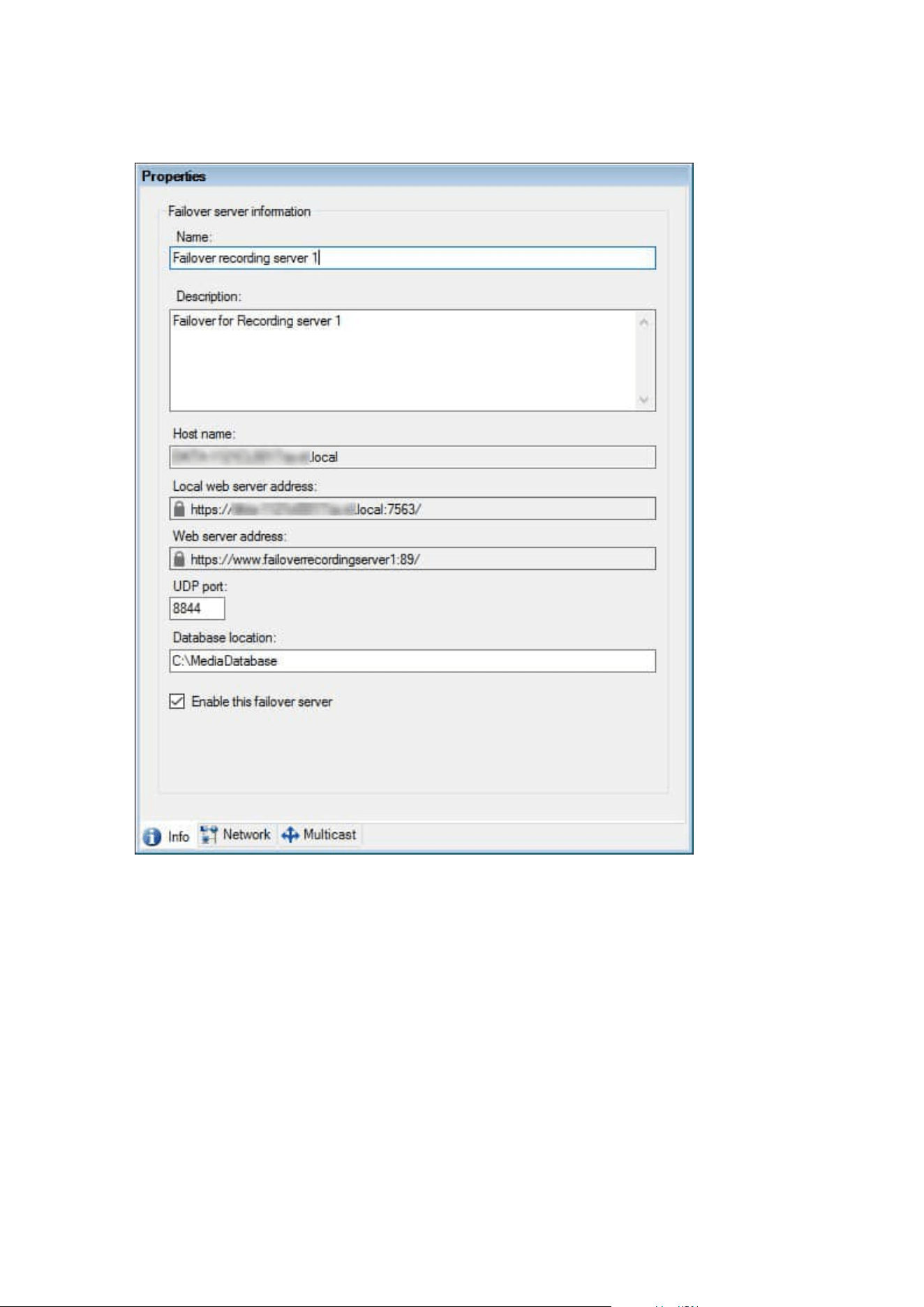
padlock icon appears in front of the local web server address and the optional web server address.
View status messages
1. On the failover recording server, right-click the Milestone Failover Recording Server service icon.
2. Select Show Status Messages. The Failover Server Status Messages window appears, listing time-
stamped status messages.
View version information
Knowing the exact version of your Failover Recording Server service is an advantage if you need to contact
product support.
Administrator manual | XProtect® VMS 2023 R1
202 | Configuration
1. On the failover recording server, right-click the Milestone Failover Recording Server service icon.
2. Select About.
3. A small dialog box opens that shows the exact version of your Failover Recording Server service.
Hardware
Add hardware
You have several options for adding hardware to each recording server in your system.
If your hardware is located behind a NAT-enabled router or a firewall, you may need to
specify a different port number and configure the router/firewall so it maps the port and
IP addresses that the hardware uses.
The Add Hardware wizard helps you detect hardware like cameras and video encoders on your network and
add them to the recording servers on your system. The wizard also helps you add remote recording servers for
Milestone Interconnect setups. Only add hardware to one recording server at a time.
1. To access Add Hardware, right-click the required recording server and select Add Hardware.
2. Select one of the wizard options (see below) and follow the instruction on the screen.
3. After installation, you can see the hardware and its devices in the Overview pane.
Certain hardware must be pre-configured when adding the hardware for the first time.
An additional Pre-configure hardware devices wizard will appear when adding such
hardware. See Hardware pre-configuration (explained) on page 51 for more information.
Add Hardware (dialog)
Hardware represents either:
l
The physical unit that connects directly to the recording server of the surveillance system via IP, for
example a camera, a video encoder, an I/O module
l
A recording server on a remote site in a Milestone Interconnect setup
For more information about how to add hardware to your system, see Add hardware on page 203.
Administrator manual | XProtect® VMS 2023 R1
203 | Configuration
Name Description
Express
(Recommended)
The system scans automatically for new hardware on the recording server's local
network.
Select the Show hardware running on other recording servers check box to see if
detected hardware is running on other recording servers.
You can select this option every time you add new hardware to your network and
want to use it in your system.
You cannot use this option to add remote systems in Milestone Interconnect
setups.
To add both HTTP and HTTPS hardware, run Express
detection with the HTTPS(Secure) radio button selected, and
then with the HTTP(Unsecure) radio button selected.
Address range
scanning
The system scans your network for relevant hardware and Milestone Interconnect
remote systems based on your specifications of:
l
hardware user names and passwords. Not needed if your hardware uses
the factory default user names and passwords
l
drivers
l
IP ranges (IPv4 only)
l
port number (default = 80)
You can select this option when you only want to scan a part of your network, for
example, when you expand your system.
Manual
Specify details about each hardware and Milestone Interconnect remote systems
separately. This can be a good choice if you want to add only a few pieces of
hardware, and you know their IP addresses, relevant user names and passwords or
if a camera does not support the automatic discovery function.
Remote connect
hardware
The system scans for hardware connected via a remotely connected server.
You can use this option if you have installed servers for, for example, the Axis One-
click Camera Connection.
You cannot use this option to add remote systems in Milestone Interconnect
setups.
Administrator manual | XProtect® VMS 2023 R1
204 | Configuration
Disable / enable hardware
Added hardware is by default enabled.
You can see if hardware is enabled or disabled in this way:
Enabled
Disabled
To disable added hardware, for example, for licensing or performance purposes
1. Expand the recording server, right-click the hardware you want to disable.
2. Select Enabled to clear or select it.
Edit hardware
Right-click on added hardware and select Edit Hardware to modify the network configuration and user
authentication settings of hardware in Management Client.
Edit Hardware (dialog)
For some hardware, the Edit Hardware dialog also lets you apply settings directly to the
hardware device.
If the Edit Management Client settings radio button is selected, the Edit Hardware dialog displays the
settings which Management Client uses to connect to the hardware. To ensure the hardware device is added
to the system properly, enter the same settings you use to connect to the manufacturer's hardware
configuration interface:
Name Description
Name Displays the name of the hardware alongside its detected IPaddress (in parenthesis).
Hardware
URL
The web address of the manufacturer's hardware configuration interface, typically
containing the IP address of the hardware. Specify a valid address in your network.
User name The user name used to connect to the hardware.
Administrator manual | XProtect® VMS 2023 R1
205 | Configuration
Name Description
The user name that you enter here does not change the user name
on the actual hardware device. Select the Edit Management Client
and hardware settings radio button to modify settings on
supported hardware devices.
Password
The password used to connect to the hardware.
The password that you enter here does not change the password
on the actual hardware device. Select the Edit Management Client
and hardware settings radio button to modify settings on
supported hardware devices.
For information about how to change passwords on multiple
hardware devices, see Change passwords on hardware devices on
page 211.
As a system administrator, you need to give other users permission to view the password
in Management Client. For more information, see Role settings under Hardware.
If the Edit Management Client and hardware settings radio button is selected (for supported hardware), the
Edit Hardware dialog displays settings which are also applied directly to the hardware device:
Applying the settings with this radio button selected will overwrite the current settings
on the hardware device. The hardware will momentarily lose connection to the recording
server while the settings are applied.
Name Description
Name Displays the name of the hardware alongside its detected IPaddress (in parenthesis).
Administrator manual | XProtect® VMS 2023 R1
206 | Configuration
Name Description
Network
Configuration
The network settings of the hardware. To adjust the network settings, select
Configure on page 207.
Configure
Specify the Internet Protocol (for supported hardware devices) using the IPversion
dropdown list.
l
For IPv4, the values must be in the format: (0-999).(0-999).(0-999).(0-999)
l
For IPv6, the values must be in the format of eight groups of hexadecimal
digits each separated by a colon. The subnet mask must be a number
between 0-128.
The Check button tests whether there is currently another hardware device in the
system that is using the entered IP address.
Check cannot detect conflicts with hardware devices that are
turn off, outside of the XProtect VMS system, or otherwise
momentarily not responding.
User name
The user name and level used to connect to the hardware. Select another user from
the dropdown list and add a new password using the Password field described
below.
Add or delete users using the underlined actions at the bottom of the
Authentication section (see Add a user on page 208 or Delete users on page 208).
Selecting a user that does not have the highest user level
specified by the manufacturer could result in some features
not being available.
Password
The password used to connect to the hardware. View the currently entered text using
the Reveal
icon.
When changing the password, consult the manufacturer's documentation for the
password rules for the specific hardware device, or use the Generate Password
icon to automatically generate a password that matches the requirements.
Administrator manual | XProtect® VMS 2023 R1
207 | Configuration
Name Description
For information about how to change passwords on multiple
hardware devices, see Change passwords on hardware devices
on page 211.
As a system administrator, you need to give other users permission to view the
password in Management Client. For more information, see Role settings under
Hardware.
Add a user
Select the underlined Add link to open the Add a User dialog and add a user to the
hardware device.
Adding a user will automatically set it as the currently active
user and overwrite the previously entered credentials.
When creating the password, consult the manufacturer's documentation for the
password rules for the specific hardware device, or use the Generate Password
icon to automatically generate a password that matches the requirements.
The highest user level detected on the hardware device will automatically be
preselected. It is not recommended to modify the User level from its default value.
Selecting a User level that is not the highest specified by the
manufacturer could result in some features not being
available.
Delete users
Select the underlined Delete link to open the Delete Users dialog and remove users
from the hardware device.
You cannot delete the currently active user. To set a new user,
use the Add a User dialog described above, then remove the
old user using this interface.
Enable / disable individual devices
Cameras are by default enabled.
Administrator manual | XProtect® VMS 2023 R1
208 | Configuration
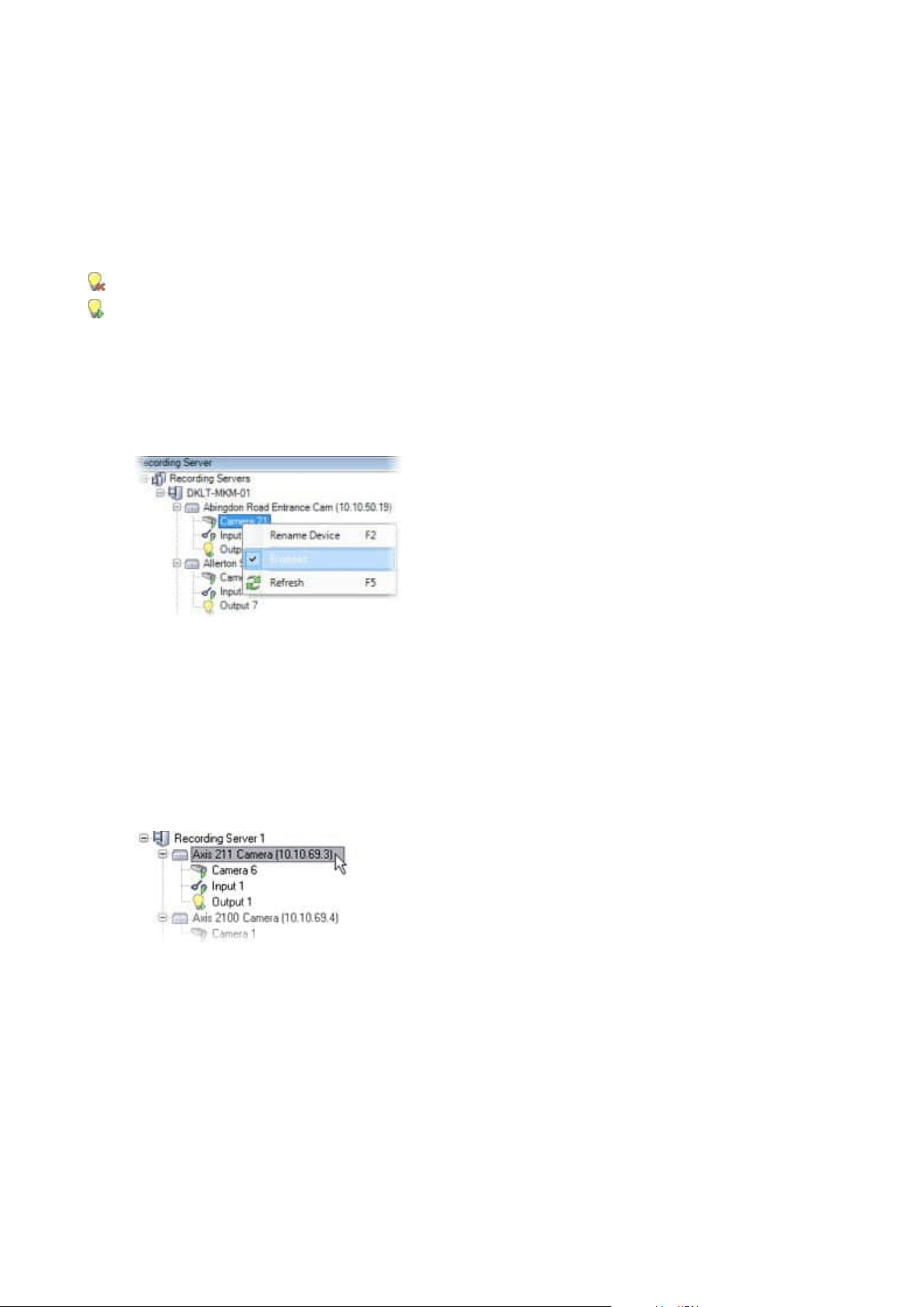
Microphones, speakers, metadata, inputs and outputs are by default disabled.
This means that microphones, speakers, metadata, inputs and outputs must be individually enabled before
you can use them in the system. The reason for this is that surveillance systems rely on cameras, whereas the
use of microphones and so on is highly individual depending on the needs of each organization.
You can see if devices are enabled or disabled (the examples show an output):
Disabled
Enabled
The same method for enabling/disabling is used for cameras, microphones, speakers, metadata, inputs, and
outputs.
1. Expand the recording server and the device. Right-click the device you want to enable.
2. Select Enabled to clear or select it.
Set up a secure connection to the hardware
You can set up a secure HTTPS connection using SSL (Secure Sockets Layer) between the hardware and the
recording server.
Consult your camera vendor to get a certificate for your hardware and upload it to the hardware, before you
continue with the steps below:
1. In the Overview pane, right-click the recording server and select the hardware.
2. On the Settings tab, enable HTTPS. This is not enabled by default.
3. Enter the port on the recording server to which the HTTPS connection is connected. The port number
must correspond with the port set up on the device’s homepage.
4. Make changes as needed and save.
Administrator manual | XProtect® VMS 2023 R1
209 | Configuration

Enable PTZ on a video encoder
To enable the use of PTZ cameras on a video encoder, do the following on the PTZ tab:
1. In the list of devices connected to the video encoder, select the Enable PTZ box for the relevant
cameras:
2. In the PTZ Device ID column, verify the ID of each camera.
3. In the COM Port column, select which video encoder's COM (serial communications) ports to use for
control of the PTZ functionality:
4. In the PTZ Protocol column, select which positioning scheme you want to use:
l
Absolute: When operators use PTZ controls for the camera, the camera is adjusted relative to a
fixed position, often referred to as the camera's home position
l
Relative: When operators use PTZ controls for the camera, the camera is adjusted relative to its
current position
The content of the PTZ protocol column varies a lot depending on the hardware. Some have 5 to 8
different protocols. See also the camera documentation.
5. In the toolbar, click Save.
6. You are ready to configure preset positions and patrolling for each PTZ camera:
l
Add a preset position (type 1)
l
Add a patrolling profile
Administrator manual | XProtect® VMS 2023 R1
210 | Configuration
Change passwords on hardware devices
Available functionality depends on the system you are using. See the complete feature
list, which is available on the product overview page on the Milestone website
(https://www.milestonesys.com/solutions/platform/product-index/).
You can change passwords on multiple hardware devices in one operation.
Initially, the supported devices are models from Canon, Axis, Bosch, Hanwa, Panasonic, Sony, Hikvision, and
ONVIF compatible hardware devices, but the user interface shows you directly if a model is supported or not.
You can also go to our website to find out if a model is supported:
https://www.milestonesys.com/community/business-partner-tools/supported-devices/
For devices that do not support device password management, you must change the
password of a hardware device from its web page and then manually enter the new
password in Management Client. For more information, see Edit hardware on page 205.
You can choose to:
l
Let the system generate individual passwords for each hardware device. The system generates
passwords based on the requirements from the manufacturer of the hardware devices.
l
Use a single user-defined password for all hardware devices. When you apply the new passwords, the
hardware devices lose connection to the recording server momentarily. After you have applied new
passwords, the result for each hardware device appears on the screen. For unsuccessful changes, the
reason for failure appears if the hardware device supports such information. From within the wizard,
you can create a report of successful and failed password changes, but the results are also logged
under Server logs.
For hardware devices with ONVIF drivers and multiple user accounts, only an
administrator of XProtect with administrative permissions of the hardware device
can change passwords from the VMS.
Requirements:
l
The hardware device model supports device password management by Milestone.
Steps:
1. In the Site Navigation pane, select the Recording Servers node.
2. Right-click the relevant recording server or hardware in the overview pane.
3. Select Change Hardware Password. A wizard appears.
Administrator manual | XProtect® VMS 2023 R1
211 | Configuration
4. Type the password using lower and upper letters, numbers, and the following characters: ! ( ) * - . _
The maximum password length is 64 characters.
The maximum password length for the Bosch FLEXIDOME IP outdoor 5000 MP
NDN-50051 camera is 19 characters.
5. Follow the instructions on the screen to complete the changes.
The Password last changed field shows the time stamp of the latest password
change based on the local time settings of the computer that the password was
changed from.
6. The last page shows the result. If the system could not update a password, click Failed next to the
hardware device to see the reason.
7. You can also click the Print report button to see the full list of successful and unsuccessful updates.
8. In case you want to change the password on the hardware devices that failed, click Retry, and the
wizard starts over with the failed hardware devices.
If you select Retry, you can no longer access the report from the first time you
completed the wizard.
Due to security restrictions, some hardware devices might become unavailable
for a certain period if you fail to change password several times in a row. Security
restrictions vary for different manufacturers.
Update firmware on hardware devices
Available functionality depends on the system you are using. See the complete feature
list, which is available on the product overview page on the Milestone website
(https://www.milestonesys.com/solutions/platform/product-index/).
Management Client allows you to update the firmware of hardware that has been added to your VMS system.
You can update firmware for multiple hardware devices simultaneously if they are compatible with the same
firmware file.
Administrator manual | XProtect® VMS 2023 R1
212 | Configuration
The user interface shows you directly if a model supports firmware updates. You can also go to the Milestone
website to find out if a model is supported: https://www.milestonesys.com/community/business-partner-
tools/supported-devices/
For devices that do not support firmware updates, you must update the firmware of a
hardware device from its web page.
When you update firmware, the hardware devices lose connection to the recording server momentarily.
After you have updated the firmware, the result for each hardware device appears on the screen. For
unsuccessful changes, the reason for failure appears if the hardware device supports such information. The
results are also logged under Server logs.
For hardware devices with ONVIF drivers and multiple user accounts, only an
administrator of XProtect with administrative permissions of the hardware device can
update firmware from the VMS.
Requirements:
l
The hardware device model supports firmware updates by Milestone.
Steps:
1. In the Site Navigation pane, select the Recording Servers node.
2. Right-click the relevant recording server or hardware in the overview pane.
3. Select Update hardware firmware. A wizard appears.
4. Follow the instructions on the screen to complete the changes.
You may only update multiple hardware devices that are compatible with the
same firmware file. Hardware that is added through the ONVIF driver is found
under other, rather than its manufacturer name.
6. The last page shows the result. If the system could not update the firmware, click Failed next to the
hardware device to see the reason.
Milestone does not take responsibility for hardware device malfunction if an
incompatible firmware file or hardware device is selected.
Administrator manual | XProtect® VMS 2023 R1
213 | Configuration
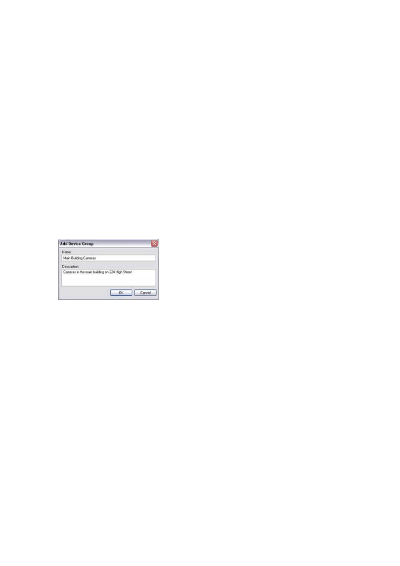
Add and configure an external IDP
1. In Management Client, select Tools > Options and open the External IDP tab.
2. In the External IDP section, select Add.
3. Enter the information for the external IDP. For more information about the information that is required,
see External IDP.
For information about how to register which claims from the external IDP that you want to use in the VMS, see
Register claims from an external IDP.
Devices - Groups
Add a device group
1. In the Overview pane, right-click the device type under which you want to create a device group.
2. Select Add Device Group.
3. In the Add Device Group dialog box, specify a name and description of the new device group:
The description appears when you pause the mouse pointer over the device group in the device group
list.
4. Click OK. A folder representing the new device group appears in the list.
5. Continue to specify which devices to include in a device group (see Specify which devices to include in a
device group on page 214).
Specify which devices to include in a device group
1. In the Overview pane, right-click the relevant device group folder.
2. Select Edit Device Group Members.
3. In the Select Group Members window, select one of the tabs to locate the device.
A device can be a member of more than one device group.
Administrator manual | XProtect® VMS 2023 R1
214 | Configuration
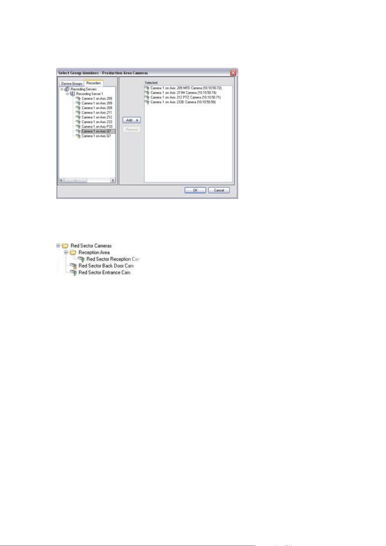
4. Select the devices you want to include, and click Add or double-click the device:
5. Click OK.
6. If you exceed the limit of 400 devices in one group, you can add device groups as subgroups under
other device groups:
Disabled Devices
Disabled devices are by default not displayed in the Overview pane.
To display all disabled devices, in the top of the Overview pane, click Filter to open the Filter tab and select
Show disabled devices.
To hide disabled devices again, clear Show disabled devices.
Specify common properties for all devices in a device group
With device groups, you can specify common properties for all devices within a given device group:
1. In the Overview pane, click the device group.
In the Properties pane, all properties which are available on all of the device group's devices are
listed and grouped on tabs.
2. Specify the relevant common properties.
On the Settings tab, you can switch between settings for all devices and settings for individual devices.
3. In the toolbar, click Save. The settings are saved on the individual devices, not in the device group.
Administrator manual | XProtect® VMS 2023 R1
215 | Configuration

Disabled devices
Disabled devices are by default not displayed in the Overview pane.
To display all disabled devices, in the top of the Overview pane, click Filter to open the Filter tab and select
Show disabled devices.
To hide disabled devices again, clear Show disabled devices.
Enable/disable devices via device groups
You can enable/disable devices only via the configured hardware. Unless manually enabled/disabled in the add
hardware wizard, camera devices are by default enabled and all other devices are by default disabled.
Disabled devices are by default not displayed in the Overview pane.
To display all disabled devices, in the top of the Overview pane, click Filter to open the Filter tab and select
Show disabled devices.
To hide disabled devices again, clear Show disabled devices.
To locate a device via the device groups to enable or disable:
1. In the Site Navigation pane, select the device.
2. In the Overview pane expand the relevant group and find the device.
3. Right-click the device, and select Go To Hardware.
4. Click the plus node to see all devices on the hardware.
5. Right-click the device you want to enable/disable, and select Enabled.
Devices - Camera settings
View or edit camera settings
1. In the Site Navigation pane, select Devices and then select Cameras.
2. Select the relevant camera in the Overview pane.
3. Open the Settings tab.
You can view or edit settings, such as:
l
Default frame rate
l
Resolution
l
Compression
l
The maximum number of frames between keyframes
l
On-screen date/time/text display for a selected camera, or for all cameras within a device group
Administrator manual | XProtect® VMS 2023 R1
216 | Configuration

The drivers for the cameras determine the content of the Settings tab. The drivers vary depending on the type
of camera.
For cameras that support more than one type of stream, for example MJPEG and MPEG-4/H.264/H.265, you can
use multi-streaming, see Manage multi-streaming on page 221.
Preview
When you change a setting, you can quickly verify the effect of your change if you have the Preview pane
enabled.
l
To enable Preview, click the View menu and then click Preview Window.
You cannot use the Preview pane to judge the effect of frame rate changes because the Preview pane's
thumbnail images use another frame rate defined in the Options dialog box.
Performance
If you change the settings for Max. frames between keyframes and Max. frames between keyframes mode,
it may lower the performance of some functionalities in XProtect Smart Client. For example, XProtect Smart
Client requires a keyframe to start up showing video, so a longer period between keyframes, prolongs the
XProtect Smart Client start up.
Enable and disable fisheye lens support
The fisheye lens support is disabled by default.
1. In the Site Navigation pane, select Devices and then select Cameras.
2. Select the relevant PTZ camera in the Overview pane.
3. On the Fisheye Lens tab, select or clear the Enable fisheye lens support check box.
Specify fisheye lens settings
1. On the Fisheye Lens tab, select the lens type.
2. Specify the physical position/orientation of the camera from the Camera position/orientation list.
3. Select a Registered Panomorph Lens (RPL) number from the ImmerVision Enables
®
panomorph RPL
number list.
This ensures the identification and correct configuration of the lens used with the camera. You usually
find the RPL number on the lens itself or on the box it came in. For details of ImmerVision, panomorph
lenses, and RPLs, see the Immervision website (https://www.immervisionenables.com/).
If you select the Generic dewarping lens profile, remember to configure the desired Field of view.
Administrator manual | XProtect® VMS 2023 R1
217 | Configuration
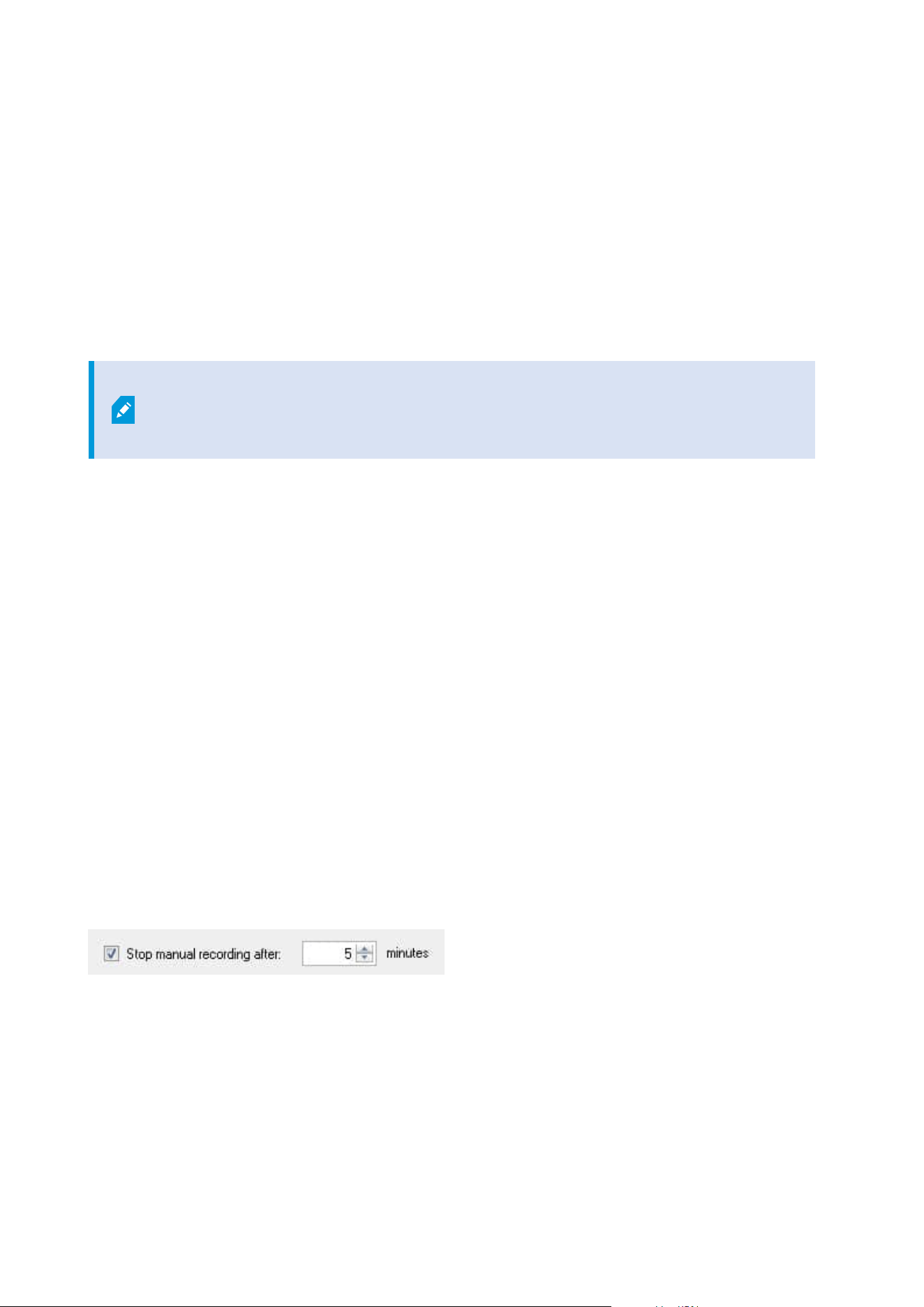
Devices - Recording
Enable/disable recording
Recording is by default enabled. To enable/disable recording:
1. In the Site Navigation pane, select Recording Servers.
2. Select the relevant device in the Overview pane.
3. On the Record tab, select or clear the Recording check box.
You must enable recording for the device before you can record data from the camera. A
rule that specifies the circumstances for a device to record does not work if you have
disabled recording for the device.
Enable recording on related devices
For camera devices, you can enable recording for related devices, for example, microphones that are
connected to the same recording server. It means that the related devices record when the camera records.
Recording on related devices are enabled by default for new camera devices, but you can disable and enable
as you want. For existing camera devices in the system, the check box is cleared by default.
1. In the Site Navigation pane, select Recording Servers.
2. Select the relevant camera device in the Overview pane.
3. On the Record tab, select or clear the Record on related devices check box.
4. On the Client tab, specify the devices that relate to this camera.
If you want to enable recording on related devices that are connected to another recording server, you must
create a rule.
Manage manual recording
Stop manual recording after is enabled by default with a recording time of five minutes. This is to ensure that
the system automatically stops all recordings started by the XProtect Smart Client users.
1. In the Site Navigation pane, select Devices.
2. Select the relevant device in the Overview pane.
3. On the Record tab, select or clear the Stop manual recording after check box.
Administrator manual | XProtect® VMS 2023 R1
218 | Configuration
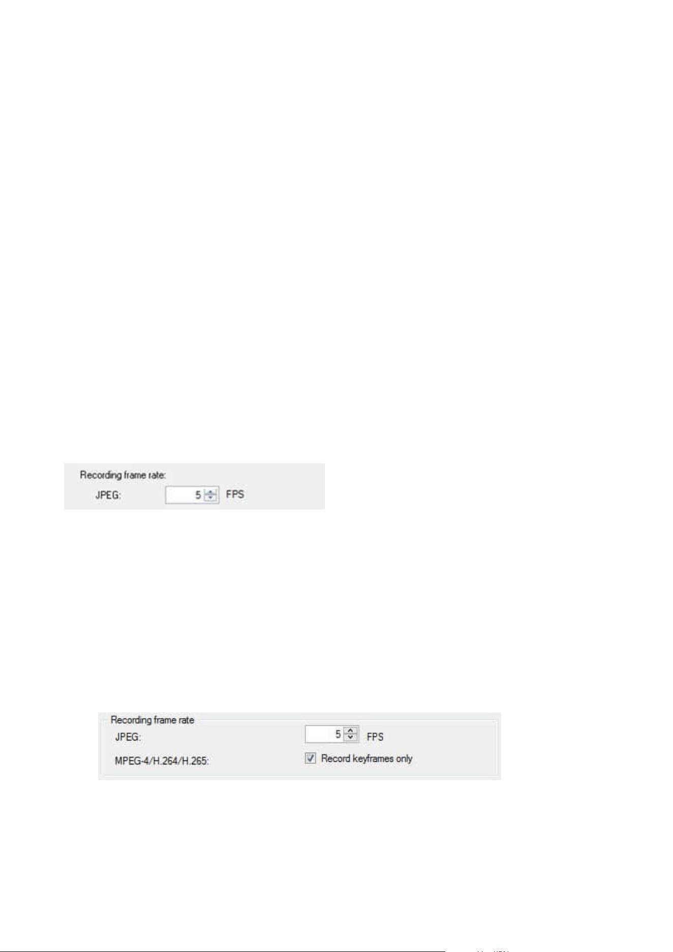
When you enable it, specify a recording time. The number of minutes you specify must be sufficiently large to
accommodate the requirements of the various manual recordings without overloading the system.
Add to roles:
You must grant the permission to start and stop manual recording to the client users on each camera in Roles
on the Device tab.
Use in rules:
The events you can use when you create rules related to manual recording are:
l
Manual Recording Started
l
Manual Recording Stopped
Specify recording frame rate
You can specify the recording frame rate for JPEG.
1. In the Site Navigation pane, select Devices.
2. Select the relevant device in the Overview pane.
3. On the Record tab, in the Recording frame rate: (JPEG) box, select or enter the recording frame rate (in
FPS, frames per second).
Enable keyframe recording
You can enable keyframe recording for MPEG-4/H.264/H.265 streams. It means that the system switches
between recording keyframes only and recording all frames depending on your rule settings.
You can, for example, let the system record keyframes when there is no motion in the view and switch to all
frames only in case of motion detection to save storage.
1. In the Site Navigation pane, select Devices.
2. Select the relevant device in the Overview pane.
3. On the Record tab, select the Record keyframes only check box.
4. Set up a rule that activates the function, see Actions and stop actions.
Administrator manual | XProtect® VMS 2023 R1
219 | Configuration

Enable recording on related devices
For camera devices, you can enable recording for related devices, for example, microphones that are
connected to the same recording server. It means that the related devices record when the camera records.
Recording on related devices are enabled by default for new camera devices, but you can disable and enable
as you want. For existing camera devices in the system, the check box is cleared by default.
1. In the Site Navigation pane, select Recording Servers.
2. Select the relevant camera device in the Overview pane.
3. On the Record tab, select or clear the Record on related devices check box.
4. On the Client tab, specify the devices that relate to this camera.
If you want to enable recording on related devices that are connected to another recording server, you must
create a rule.
Save and retrieve remote recording
To ensure that all remote recordings are saved in case of network issues, you can enable automatic retrieval of
recordings once connection is re-established.
1. In the Site Navigation pane, select Devices.
2. Select the relevant device in the Overview pane.
3. Under Remote recordings, select Automatically retrieve remote recordings when connection is
restored. This enables automatic retrieval of recordings once connection is re-established
The remote recording option is only available if the selected camera supports edge
storage or is a camera in a Milestone Interconnect setup.
The type of hardware selected determines where recordings are retrieved from:
l
For a camera with local recording storage, recordings are retrieved from the camera's local recording
storage
l
For a Milestone Interconnect remote system, recordings are retrieved from the remote systems'
recording servers
You can use the following functionality independently of the automatic retrieval:
l
Manual recording
l
The Retrieve and store remote recordings from <devices> rule
l
The Retrieve and store remote recordings between <start and end time> from <devices> rule
Administrator manual | XProtect® VMS 2023 R1
220 | Configuration
Delete recordings
1. In the Site Navigation pane, select Devices.
2. Select the relevant device in the Overview pane and select the Recording tab.
3. Click the Delete All Recordings button to delete all recordings for the device or device group.
This method can only be used if you have added all devices in the group to the same server. Protected data is
not deleted.
Devices - Streaming
Add a stream
1. On the Streams tab, click Add. This adds a second stream to the list.
2. In the Name column, edit the name of the stream. The name appears in XProtect Smart Client.
3. In the Live Mode column, select when live streaming is needed:
l
Always: the stream runs even if no XProtect Smart Client users request the stream
l
Never: the stream is off. Only use this for recording streams, for example, if you want recordings
in high quality and need the bandwidth
l
When needed: the stream starts when a user of XProtect Smart Client requests for it
4. In the Default column, select which stream is default.
5. In the Record column, select the check box if you want to record this stream or leave it cleared if you
only want to use it for live video.
6. Click Save.
If you set a stream to Default or Record, the stream is always running independent of
the Live Mode setting. Selecting When needed and Always have the same effect in the
system and if you select Never, the stream is running, but cannot be viewed live.
If you do not want the streams to run at all unless someone is viewing live video, you can
modify the Default Start Feed Rule to start on request with the predefined Live Client
Feed Requested event.
Manage multi-streaming
Viewing live video and playing back recorded video do not necessarily require the same video quality and
frame rate. You can have either one stream for live viewing and another stream for playback purposes or
multiple separate live streams with different resolution, encoding, and frame rate settings.
Administrator manual | XProtect® VMS 2023 R1
221 | Configuration

To change which stream to use for recording
For live streaming, you can set up and use as many live streams as the camera supports, but you can only
select one stream for recording at a time.
1. In the Site Navigation pane, select Devices.
2. Select the relevant camera in the Overview pane.
3. On the Streams tab, select the Record check box for the stream to be recorded.
Limit data transmission
You can set up a set of conditions to ensure that video streams only run when viewed by a client.
To manage streaming and limit unnecessary data transmission, streaming does not start when the following
conditions are met:
1. In the Site Navigation pane, select Devices.
2. Select the relevant camera in the Overview pane.
3. On the Streams tab, on the Live Mode list, select When needed.
4. On the Record tab, clear the Recording check box.
5. On the Motion tab, clear the Motion detection check box.
If these conditions are met, video streams will only run when viewed by a client.
Examples
Example 1, live and recorded video:
l
For viewing live video, your organization may prefer H.264 at a high frame rate
l
For playing back recorded video, your organization may prefer MJPEG at a lower frame rate to preserve
disk space
Example 2, local and remote live video:
l
For viewing live video from a local connected operating point, your organization may prefer H.264 at
a high frame rate to have the highest quality of video available
l
For viewing live video from a remotely connected operating point, your organization may prefer
MJPEG at a lower frame rate and quality to preserve network bandwidth
Example 3, adaptive streaming:
l
For viewing live video and decreasing the load on the CPU and GPU of the XProtect Smart Client
computer, your organization may prefer multiple high frame rate H.264/H.265 but with different
resolutions to match the resolution requested by XProtect Smart Client when using adaptive streaming.
For more information, see Smart Client Profiles (Client node) on page 450.
Administrator manual | XProtect® VMS 2023 R1
222 | Configuration
If you enable Live multicast on the camera's Client tab (see Client tab (devices)), it only
works on the default video stream.
Even when cameras support multi-streaming, individual multi-streaming capabilities may vary between
different cameras. See the camera's documentation for more information.
To see if a camera offers different types of streams, see Settings tab (devices).
Devices - Storage
Manage pre-buffering
Cameras, microphones and speakers support pre-buffering. For speakers, the streams are only sent when the
XProtect Smart Client user uses the Talk to speaker function. This means that depending on how your speaker
streams are triggered to be recorded there is little or no pre-buffering available.
In most cases, you set up speakers to record when the XProtect Smart Client user uses the Talk to speaker
function. In such cases, no speaker pre-buffer is available.
To use the pre-buffer function, the devices must be enabled and sending a stream to the
system.
Enable and disable pre-buffering
Pre-buffering is enabled by default with a pre-buffer size of three seconds and storage to the memory.
1. In the Site Navigation pane, select Devices.
2. Select the relevant device in the Overview pane.
3. On the Record tab, select or clear the Pre-buffer check box.
4. On the Client tab, specify the devices that relate to this camera.
Specify storage location and pre-buffer period
Temporary pre-buffer recordings are stored either in the memory or on the disk:
1. In the Site Navigation pane, select Devices.
2. Select the relevant device in the Overview pane and select the Record tab.
3. On the Location list, select Memory or Disk, and specify the number of seconds.
4. If you require a pre-buffer period of more than 15 seconds, select Disk.
Administrator manual | XProtect® VMS 2023 R1
223 | Configuration
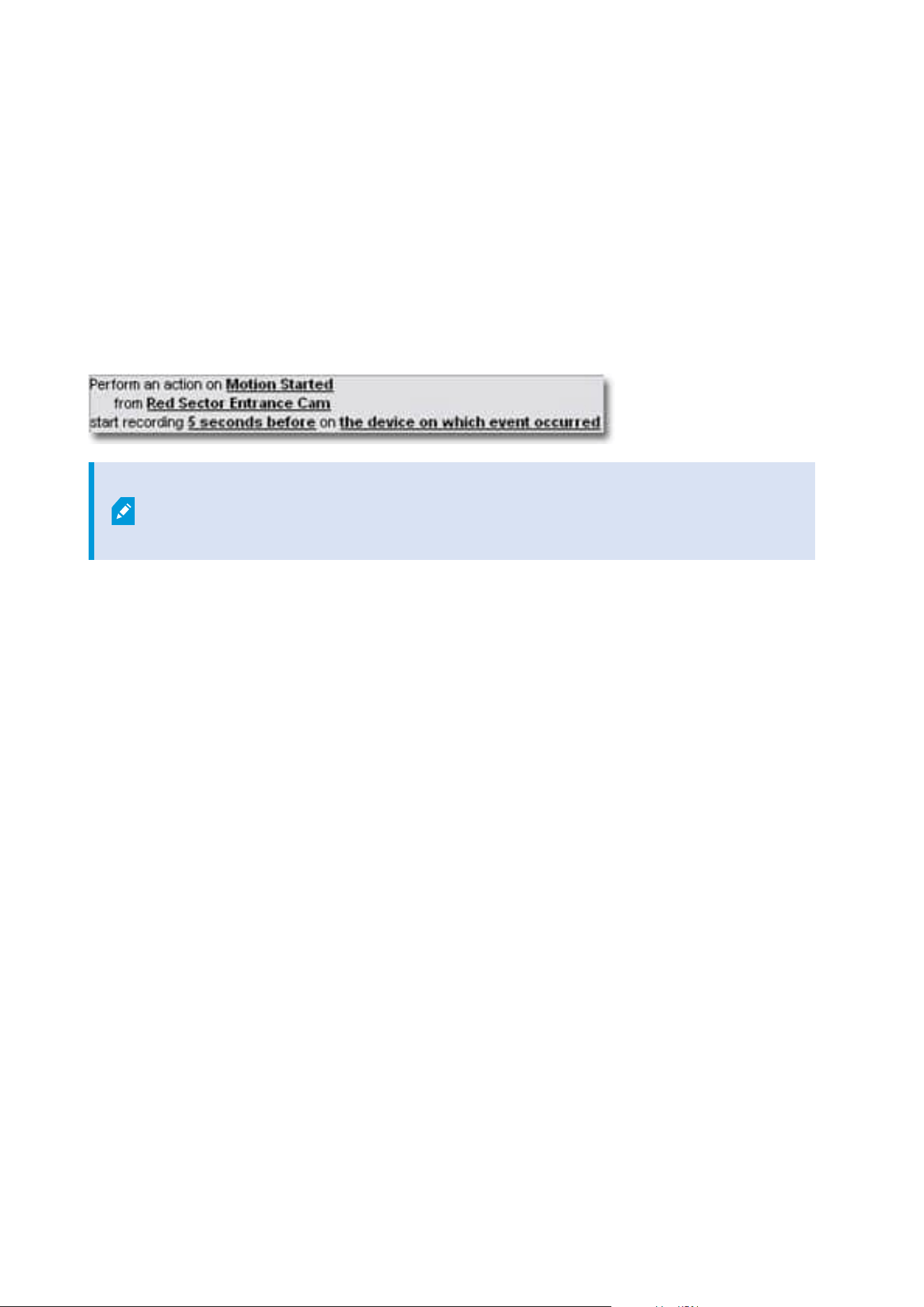
The number of seconds you specify must be sufficiently large to accommodate your requirements in the
various recording rules you define.
If you change the location to Memory, the system reduced the period to 15 seconds automatically.
Use pre-buffer in rules
When you create rules that trigger recording, you can select that recordings should start some time before the
actual event (pre-buffer).
Example: The below rule specifies that recording should start on the camera 5 seconds before motion is
detected on the camera.
To use the pre-buffer recording function in the rule, you must enable pre-buffering on
the device being recorded and you must set the pre-buffer length to at least the same
length as specified in the rule.
Monitor the status of databases for devices
1. In the Site Navigation pane, select Devices.
2. Select the relevant device in the Overview pane and select the Recording tab.
Under Storage, you can monitor and manage the databases for a device or a group of devices added to the
same recording server.
Above the table, you can see the selected database and its status. In this example, the selected database is the
default Local Default and the status is Recordings also located on other recording servers. The other server
is the recording server in building A.
Administrator manual | XProtect® VMS 2023 R1
224 | Configuration
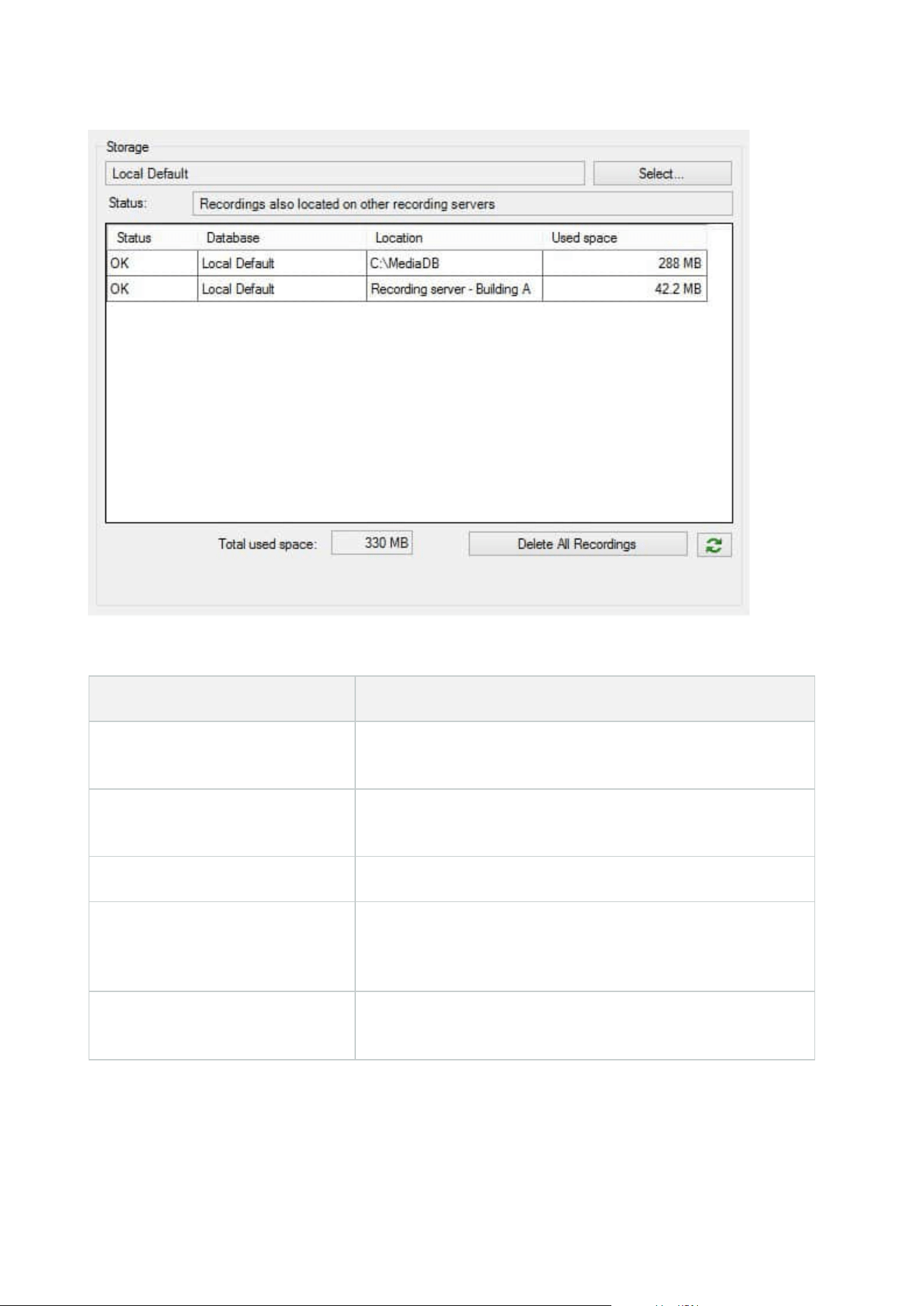
Possible statuses for selected database
Name Description
Recordings also located on other
recording servers
The database is active and running and has recordings located in
storages on other recording servers as well.
Archives also located in old storage
The database is active and running and has archives located in
other storages as well.
Active The database is active and running.
Data for some of the devices
chosen is currently moving to
another location
The database is active and running and the system is moving data
for one or more selected devices in a group from one location to
another.
Data for the device is currently
moving to another location
The database is active and running and the system is moving data
for the selected device from one location to another.
Administrator manual | XProtect® VMS 2023 R1
225 | Configuration
Name Description
Information unavailable in failover
mode
The system cannot collect status information about the database
when the database is in failover mode.
Further down in the window, you can see the status of each database (OK, Offline or Old Storage), the location
of each database and how much space each database uses.
If all servers are online, you can see the total spaced used for the entire storage in the Total used space field.
For information about configuration of storage, see Storage tab (recording server).
Move devices from one storage to another
When you select a new location to store recordings, the existing recordings will not be
moved. They will remain in the current location, with the conditions defined by the
configuration of the storage they belong to.
1. In the Site Navigation pane, select Devices.
2. Select the relevant device in the Overview pane and select the Recording tab.
3. Click Select under Storage to select a recording storage for your devices to record in.
The recordings will archive according to the configuration for the storage that you select.
Devices - Motion detection
Motion detection (explained)
Motion detection configuration is a key element in your system: Your motion detection configuration
determines when the system generates motion events and typically also when video is recorded.
Time spent on finding the best possible motion detection configuration for each camera helps you later avoid,
for example, unnecessary recordings. Depending on the physical location of the camera, it may be a good idea
to test motion detection settings under different physical conditions such as day/night and windy/calm
weather.
You can specify settings related to the amount of changes required in a camera's view in order for the change
to be regarded as motion. You can, for example, specify intervals between motion detection analysis and areas
of a view in which motion should be ignored. You can also adjust the accuracy of the motion detection and
thereby the load on system resources.
Administrator manual | XProtect® VMS 2023 R1
226 | Configuration
Image quality
Before you configure motion detection for a camera, Milestone recommends that you have configured the
camera's image quality settings, for example resolution, video codec and stream settings. You do this on the
Settings tab in the Properties window for the device. If you later change image quality settings, you should
always test any motion detection configuration afterwards.
Privacy masks
If you have defined areas with permanent privacy masks, there is no motion detection
within these areas.
Enable and disable motion detection
Specify the default setting of motion detection for cameras
1. On the Tools menu, click Options.
2. On the General tab, under When adding new camera devices automatically enable, select the Motion
detection check box.
Enable or disable motion detection for a specific camera
1. In the Site Navigation pane, select Devices and then select Cameras.
2. Select the relevant camera in the Overview pane.
3. On the Motion tab tab, select or clear the Motion detection check box.
When you disable motion detection for a camera, motion detection-related rules for the
camera do not work.
Enable or disable hardware acceleration
Automatic hardware accelerated video decoding for motion detection is the default setting when you add a
camera. The recording server is using GPU resources if they are available. This will reduce the CPU load during
video motion analysis and improve the general performance of the recording server.
To enable or disable hardware acceleration
1. In the Site Navigation pane, select Devices.
2. Select the relevant camera in the Overview pane.
3. On the Motion tab, under Hardware acceleration select Automatic to enable hardware acceleration or
select Off to disable the setting.
Administrator manual | XProtect® VMS 2023 R1
227 | Configuration
Use of GPU resources
Hardware accelerated video decoding for motion detection uses GPU resources on:
l
Intel CPUs that support Intel Quick Sync
l
NVIDIA
®
display adapters connected to your recording server
Load balancing and performance
The load balancing between the different resources is done automatically. In the System Monitor node you
can verify if the current motion analysis load on the NVIDIA GPU resources is within the specified limits from
the System Monitor Thresholds node. The NVIDIA GPU load indicators are:
l
NVIDIA decoding
l
NVIDIA memory
l
NVIDIA rendering
If the load is too high, you can add GPU resources to your recording server by installing
multiple NVIDIA display adapters. Milestone does not recommend the use of Scalable
Link Interface (SLI) configuration of your NVIDIA display adapters.
NVIDIA products have different compute capabilities.
Hardware accelerated video decoding for motion detection using NVIDIA GPUs requires
compute capability version 6.x (Pascal) or newer.
l
To find the compute capability version of your NVIDIA product, visit the NVIDIA website
(https://developer.nvidia.com/cuda-gpus/).
l
To see if video motion detection is hardware accelerated for a specific camera, enable logging on the
recoding server log file. Set level to Debug and diagnostics is logged to the DeviceHandling.log. The log
follows the pattern:
[time] [274] DEBUG – [guid] [name] Configured decoding: Automatic: Actual decoding: Intel/NVIDIA
The OS version of the recording server and CPU generation may impact performance of hardware accelerated
video motion detection. GPU memory allocation is often the bottleneck with older versions (typical limit is
between 0.5 GB and 1.7 GB).
Systems based on Windows 10 / Server 2016 and 6th generation CPU (Skylake) or newer can allocate 50% of
system memory to GPU and thereby removing or reducing this bottleneck.
6th generation Intel CPUs does provide hardware accelerated decoding of H.265, so the performance is
comparable with H.264 for these versions of CPU.
Administrator manual | XProtect® VMS 2023 R1
228 | Configuration
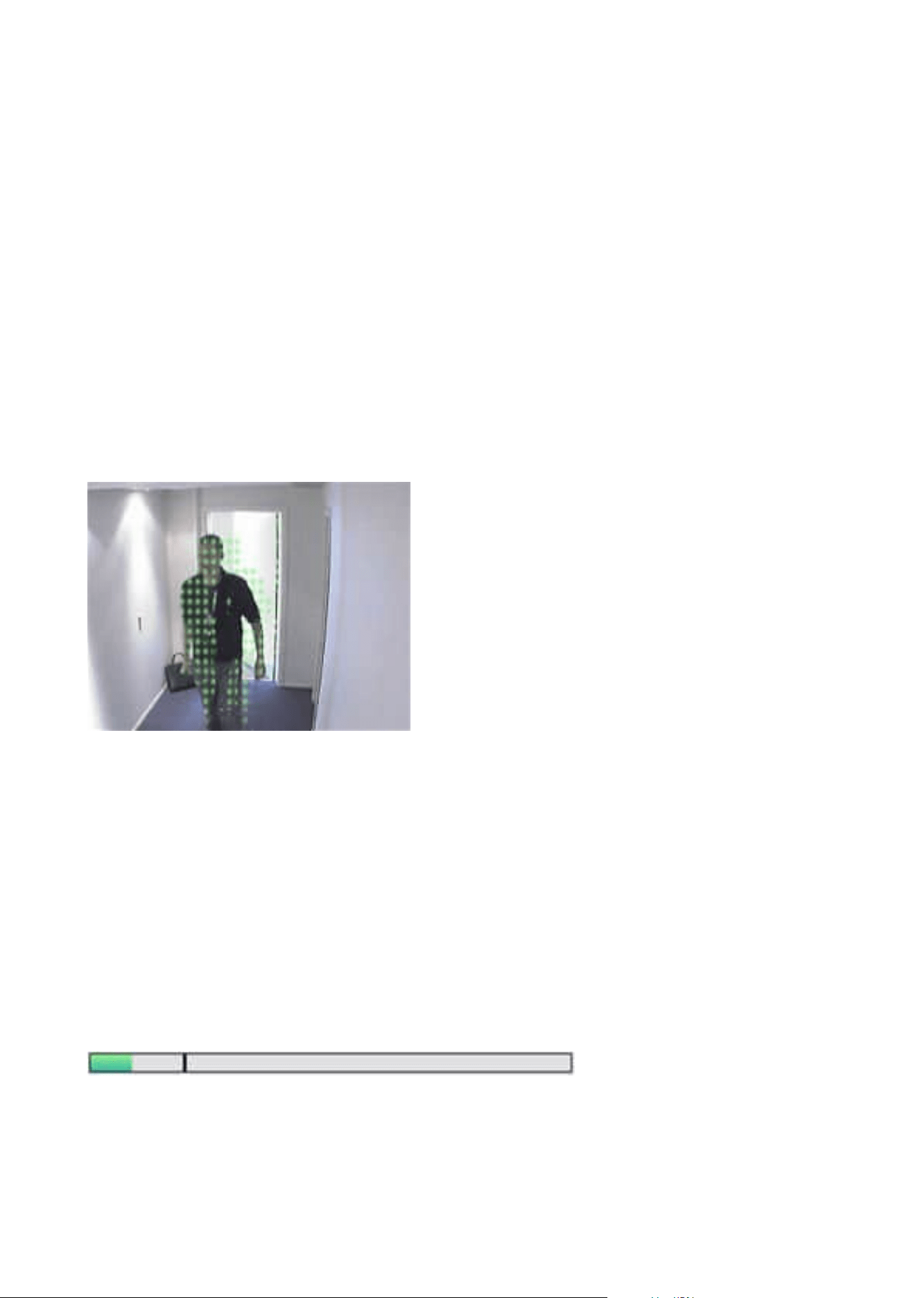
Enable manual sensitivity to define motion
The sensitivity setting determines how much each pixel in the image must change before it is regarded as
motion.
1. In the Site Navigation pane, select Devices, and then select Cameras.
2. Select the relevant camera in the Overview pane.
3. Select the Motion tab's Manual Sensitivity check box.
4. Drag the slider to the left for a higher sensitivity level, and to the right for a lower sensitivity level.
The higher the sensitivity level, the less change is allowed in each pixel before it is regarded as motion.
The lower the sensitivity level, the more change in each pixel is allowed before it is regarded as motion.
Pixels in which motion is detected are highlighted in green in the preview image.
5. Select a slider position in which only detections you consider motion are highlighted.
You can compare and set the exact sensitivity setting between cameras by the number in the right side of the
slider.
Specify threshold to define motion
The motion detection threshold determines how many pixels in the image must change before it is regarded
as motion.
1. Drag the slider to the left for a higher motion level, and to the right for a lower motion level.
2. Select a slider position in which only detections that you consider motion are detected.
The black vertical line in the motion indication bar shows the motion detection threshold: When detected
motion is above the selected detection threshold level, the bar changes color from green to red, indicating a
positive detection.
Administrator manual | XProtect® VMS 2023 R1
229 | Configuration
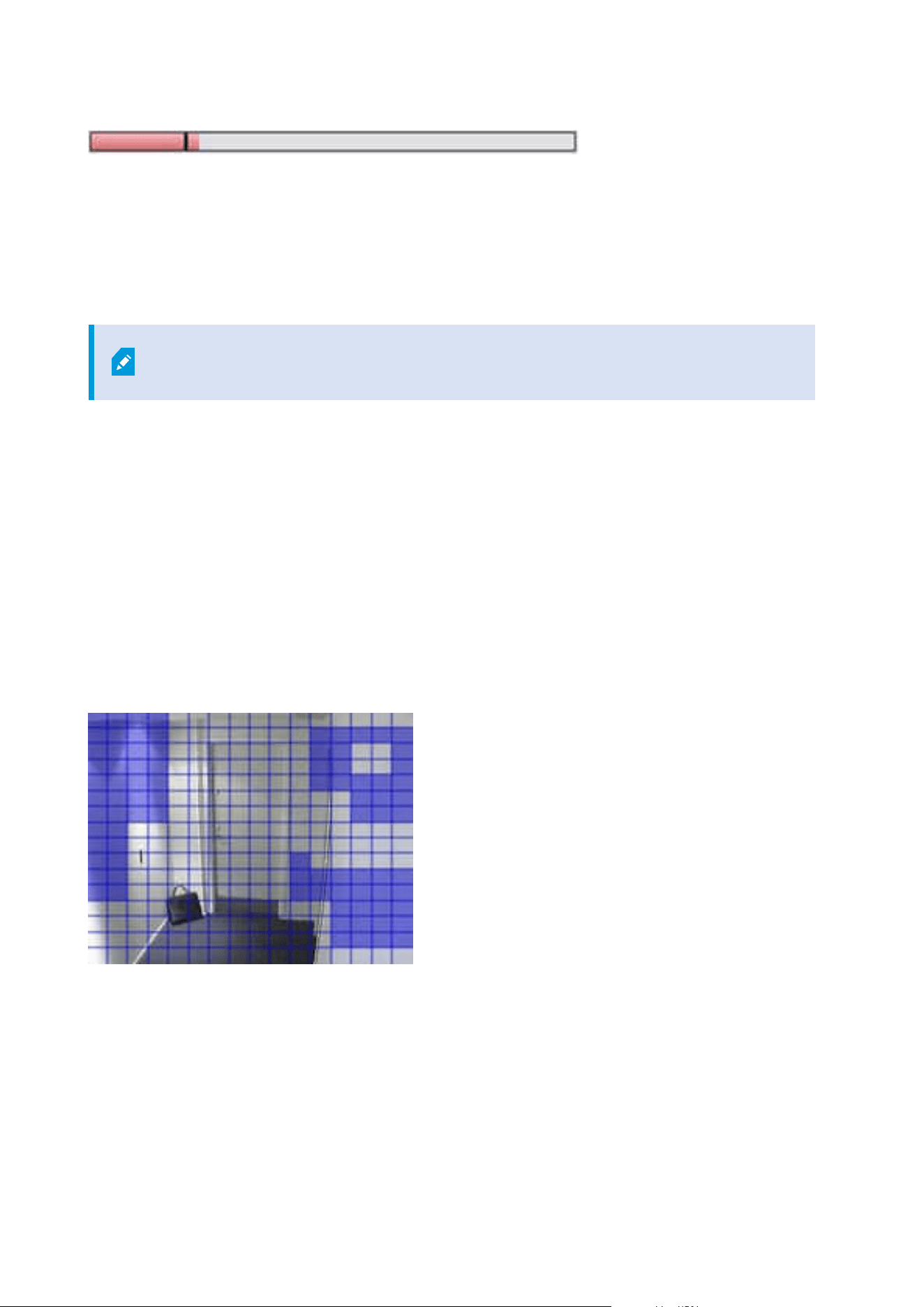
Motion indication bar: changes color from green to red when above the threshold, indicating a positive motion
detection.
Specify exclude regions for motion detection
You can configure all the settings for a group of cameras, but you would typically set the exclude regions per
camera.
Areas with permanent privacy masks, are also excluded from motion detection. Select
the Show privacy masks check box to display them.
Excluding motion detection from specific areas helps you avoid detection of irrelevant motion, for example if
the camera covers an area where a tree is swaying in the wind or where cars regularly pass by in the
background.
When you use exclude regions with PTZ cameras and you pan-tilt-zoom the camera, the excluded area does
not move accordingly because the area is locked to the camera image, and not the object.
1. To use exclude regions, select the Use exclude regions check box.
A grid divides the preview image into selectable sections.
2. To define exclude regions, drag the mouse pointer over the required areas in the preview image while
you press the left mouse button. Right mouse button clears a grid section.
You can define as many exclude regions as needed. Excluded regions appear in blue:
The blue exclude areas only appear in the preview image on the Motion tab, not in any other preview images
in the Management Client or access clients.
Administrator manual | XProtect® VMS 2023 R1
230 | Configuration

Devices - Preset camera positions
The Home preset position
You define a camera's Home preset position on the camera's homepage. The PTZ capabilities available on the
homepage depend on the camera.
Add a preset position (type 1)
To add a preset position for the camera:
Administrator manual | XProtect® VMS 2023 R1
231 | Configuration
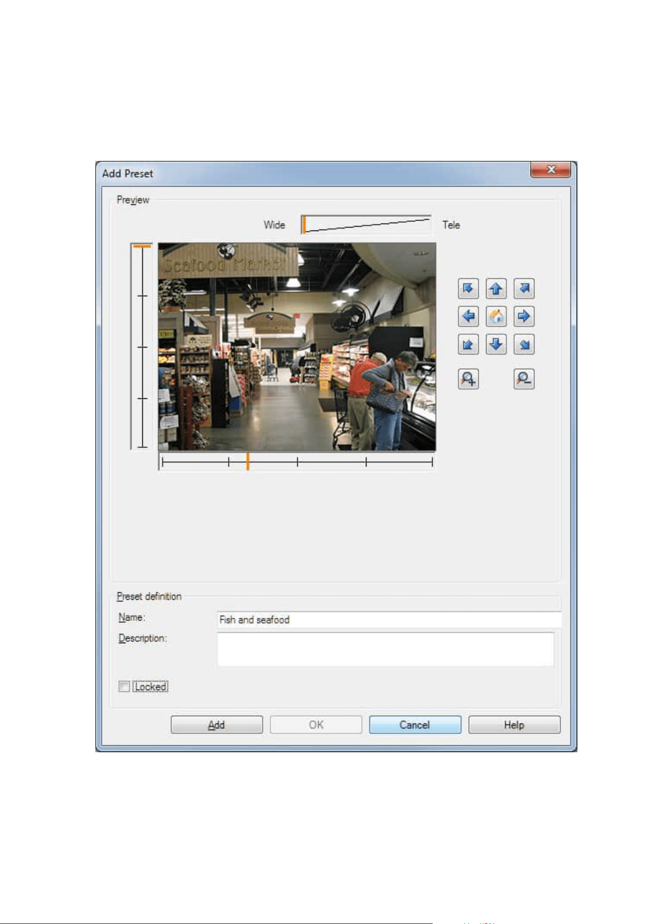
1. In the Site Navigation pane, select Devices and then select Cameras.
2. Select the relevant PTZ camera in the Overview pane.
3. On the Presets tab, click New. The Add Preset window appears:
Administrator manual | XProtect® VMS 2023 R1
232 | Configuration

4. The Add Preset window displays a live preview image from the camera. Use the navigation buttons
and/or sliders to move the camera to the required position.
5. Specify a name for the preset position in the Name field.
6. Optionally, enter a description of the preset position in the Description field.
7. Select Locked if you want to lock the preset position. Only users with sufficient permissions can unlock
the position afterwards.
8. Click Add to specify presets. Keep adding until you have the presets you want.
9. Click OK. The Add Preset window closes, and adds the position to the Presets tab's list of available
preset positions for the camera.
Use preset positions from the camera (type 2)
As an alternative to specifying preset positions in the system, you can specify preset positions for some PTZ
cameras on the camera itself. You can typically do this by accessing a product-specific configuration web page.
1. In the Site Navigation pane, select Devices and then select Cameras.
2. Select the relevant PTZ camera in the Overview pane.
3. On the Presets tab, select Use presets from device to import the presets into the system.
Any presets you have previously defined for the camera are deleted and affect any defined rules and
patrolling schedules as well as remove the presets available for the XProtect Smart Client users.
4. Click Delete to delete presets that your users do not need.
5. Click Edit if you want to change the display name of the preset (see Rename a preset position (type 2
only)).
6. If you later want to edit such device-defined presets, edit on the camera and then re-import.
Assign a camera's preset position as default
If required, you can assign one of a PTZ camera's preset positions as the camera's default preset position.
It can be useful to have a default preset position because it allows you to define rules that specify that the PTZ
camera should go to the default preset position under particular circumstances, for example after you have
operated the PTZ camera manually.
1. In the Site Navigation pane, select Devices and then select Cameras.
2. Select the relevant PTZ camera in the Overview pane.
3. On the Presets tab, under Preset positions, select the preset in your list of defined preset positions.
4. Select the Default preset check box below the list.
You can only define one preset position as the default preset position.
Administrator manual | XProtect® VMS 2023 R1
233 | Configuration

If you have selected Use default preset as PTZ home position in Options > General, the default preset
position will be used instead of PTZ camera’s defined home position.
Specify the default preset as the PTZ Home position
Management Client and XProtect Smart Client users with the necessary user permissions can set up the
system to use the default preset position instead of the home position of PTZ cameras with the Home button
in a client.
A default preset position must be defined for the camera. If a default preset position is not defined, nothing
will happen when activating the Home button in a client.
Enable setting the PTZ home position
1. Select Tools > Options.
2. On the General tab, in the Recording Server group, select Use default preset as PTZ home position.
3. Assign a preset position as the default preset position for the camera.
To assign a default preset position, see Assign a camera's preset position as default on page 233
See also System settings (Options dialog box) on page 365
Edit a preset position for a camera (type 1 only)
To edit an existing preset position defined in the system:
1. In the Site Navigation pane, select Devices, and then select Cameras.
2. Select the relevant camera in the Overview pane.
3. On the Presets tab, under Preset positions, select the preset position in the list of available preset
positions for the camera.
Administrator manual | XProtect® VMS 2023 R1
234 | Configuration
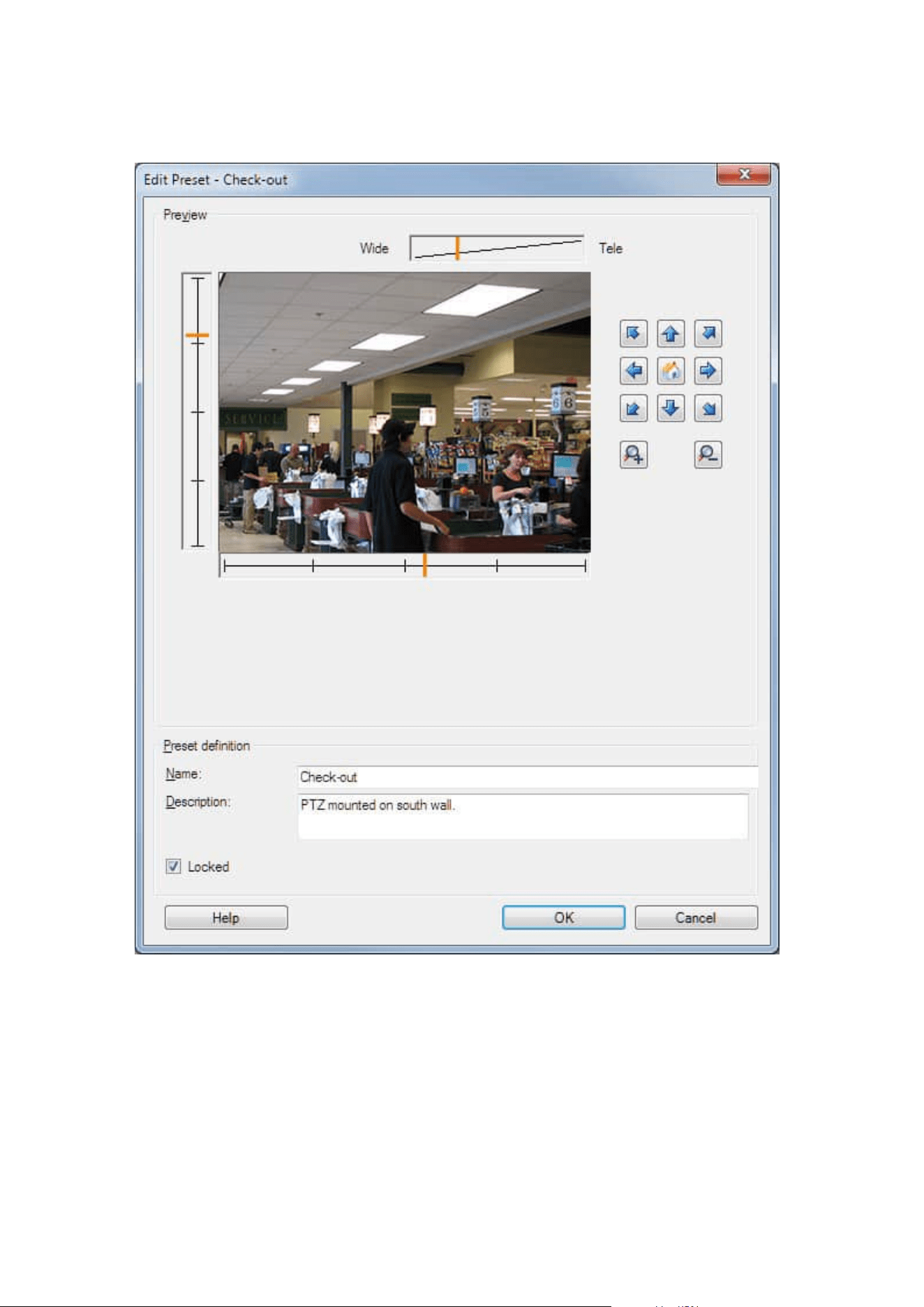
4. Click Edit. This opens the Edit Preset window:
5. The Edit Preset window displays live video from the preset position. Use the navigation buttons and/or
sliders to change the preset position as required.
6. Change the name/number and description of the preset position if needed.
7. Select Locked if you want to lock the preset position. Only users with sufficient permissions can unlock
the position afterwards.
Administrator manual | XProtect® VMS 2023 R1
235 | Configuration
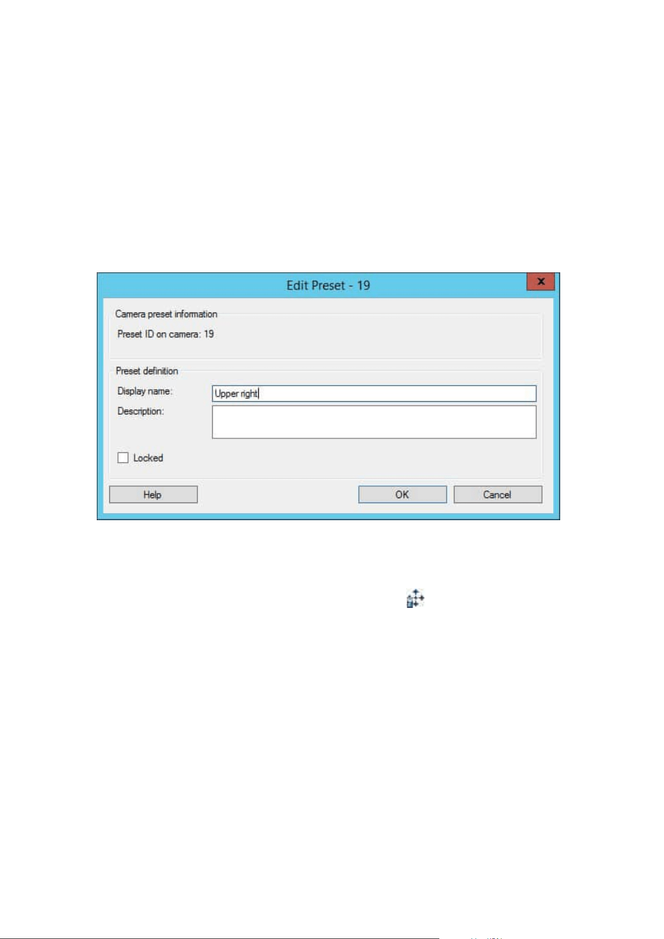
8. Click OK.
Rename a preset position for a camera (type 2 only)
To edit the name of a preset position defined in the camera:
1. In the Site Navigation pane, select Devices and then select Cameras.
2. Select the relevant PTZ camera in the Overview pane.
3. Select the preset position in the Presets tab's list of available presets for the camera.
4. Click Edit. This opens the Edit Preset window:
5. Change the name and add a description of the preset position if needed.
6. Select Locked if you want to lock the preset name. You can lock a preset name if you want to prevent
users in XProtect Smart Client or users with limited security permissions from updating the preset name
or deleting the preset. Locked presets are indicated with this icon
. Only users with sufficient
permissions can unlock the preset name afterwards.
7. Click OK.
Test a preset position (type 1 only)
1. In the Site Navigation pane, select Devices and then select Cameras.
2. Select the relevant PTZ camera in the Overview pane.
3. Select the preset position in the Presets tab's list of available preset positions for the camera.
4. Click Activate.
Administrator manual | XProtect® VMS 2023 R1
236 | Configuration

5. The camera moves to the selected preset position.
Devices - Patrolling
Patrolling profiles and manual patrolling (explained)
Patrolling profiles are the definitions of how patrolling should take place. This includes the order in which the
camera should move between preset positions and how long it should remain at each position. You can create
an unrestricted number of patrolling profiles and use them in your rules. For example, you may create a rule
specifying that one patrolling profile should be used during daytime opening hours and another during nights.
Manual patrolling
Before you apply a patrolling profile in a rule, for example, you can test the patrolling profile with manual
patrolling. You can also use manual patrolling to take over patrolling from another user or from a rule-
activated patrolling, provided that you have a higher PTZ priority.
If the camera is already patrolling or controlled by another user, you can only start manual patrolling if you
have a higher priority.
If you start a manual patrolling while the camera runs a rule-activated system patrolling, the system resumes
this patrolling when you stop your manual patrolling. If another user runs a manual patrolling, but you have a
higher priority and start your manual patrolling, the other user's manual patrolling is not resumed.
If you do not stop your manual patrolling yourself, it will continue until a rule-based patrolling or a user with a
higher priority takes over. When the rule-based system patrolling stops, the system resumes your manual
patrolling. If another user starts a manual patrolling, your manual patrolling stops, and will not be resumed.
When you stop your manual patrolling and you have defined an end position for your patrolling profile, the
camera returns to this position.
Add a patrolling profile
Before you can work with patrolling, you must specify at least two preset positions for
the camera in the Presets tab, see Add a preset position (type 1).
1. In the Site Navigation pane, select Devices and then select Cameras.
2. Select the relevant PTZ camera in the Overview pane.
3. On the Patrolling tab, click Add. The Add Profile dialog box appears.
4. In the Add Profile dialog box, specify a name for the patrolling profile.
5. Click OK. The button is disabled if the name is not unique.
Administrator manual | XProtect® VMS 2023 R1
237 | Configuration
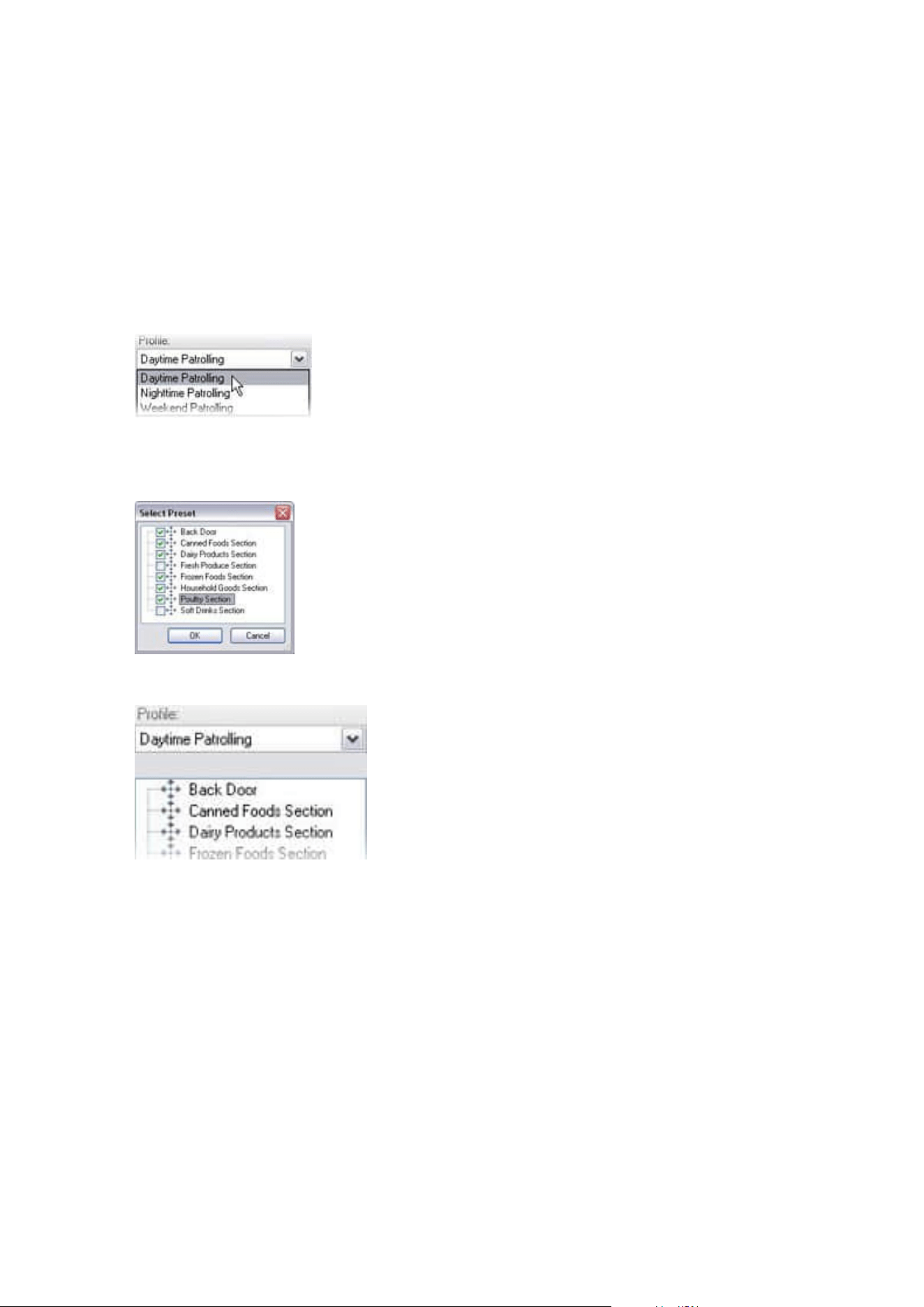
The new patrolling profile is added to the Profile list. You can now specify the preset positions and other
settings for the patrolling profile.
Specify preset positions in a patrolling profile
1. In the Site Navigation pane, select Devices and then select Cameras.
2. Select the relevant PTZ camera in the Overview pane.
3. On the Patrolling tab, select the patrolling profile in the Profile list:
4. Click Add.
5. In the Select PTZ Preset dialog box, select the preset positions for your patrolling profile:
6. Click OK. The selected preset positions are added to the list of preset positions for the patrolling profile:
7. The camera uses the preset position at the top of the list as the first stop when it patrols according to
the patrolling profile. The preset position in the second position from the top is the second stop, and so
forth.
Specify the time at each preset position
When patrolling, the PTZ camera by default remains for 5 seconds at each preset position specified in the
patrolling profile.
To change the number of seconds:
Administrator manual | XProtect® VMS 2023 R1
238 | Configuration
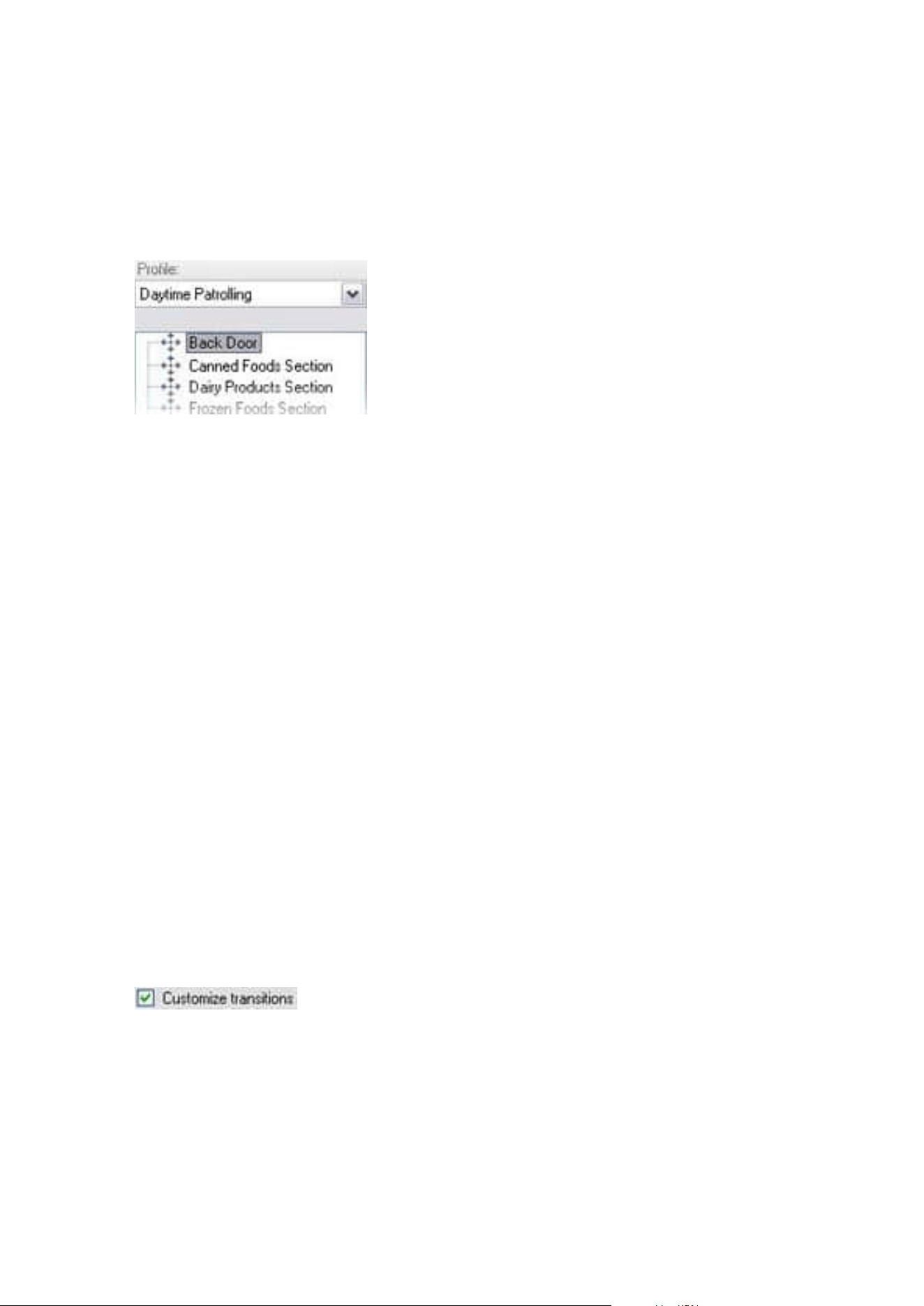
1. In the Site Navigation pane, select Devices and then select Cameras.
2. Select the relevant PTZ camera in the Overview pane.
3. On the Patrolling tab, select the patrolling profile in the Profile list.
4. Select the preset position for which you want to change the time:
5. Specify the time in the Time on position (sec) field.
6. If required, repeat for other preset positions.
Customize transitions (PTZ)
By default, the time required for moving the camera from one preset position to another, known as transition,
is estimated to be three seconds. During this time, motion detection is by default disabled on the camera,
because irrelevant motion is otherwise likely to be detected while the camera moves between the preset
positions.
You can only customize speed for transitions if your camera supports PTZ scanning and is of the type where
preset positions are configured and stored on your system's server (type 1 PTZ camera). Otherwise the Speed
slider is grayed out.
You can customize the following:
l
The estimated transition time
l
The speed with which the camera moves during a transition
To customize transitions between the different preset positions:
1. In the Site Navigation pane, select Devices and then select Cameras.
2. Select the relevant PTZ camera in the Overview pane.
3. On the Patrolling tab, in the Profile list, select the patrolling profile .
4. Select the Customize transitions check box.
Transition indications are added to the list of preset positions.
Administrator manual | XProtect® VMS 2023 R1
239 | Configuration
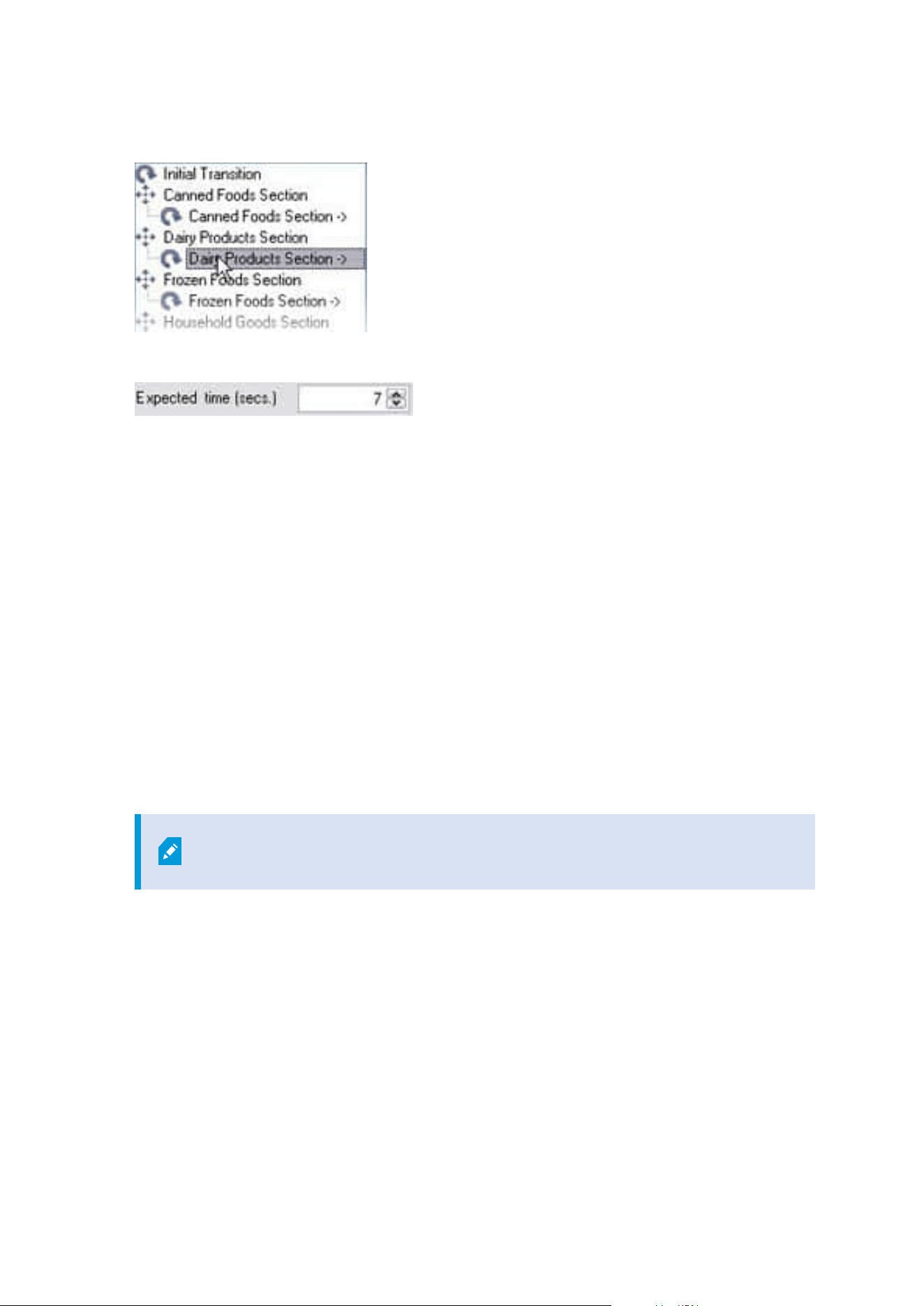
5. In the list, select the transition.
6. Specify the estimated transition time (in number of seconds) in the Expected time (sec) field.
7. Use the Speed slider to specify the transition speed. When the slider is in its rightmost position, the
camera moves with its default speed. The more you move the slider to the left, the slower the camera
moves during the selected transition.
8. Repeat as required for other transitions.
Specify an end position when patrolling
You can specify that the camera should move to a specific preset position when patrolling according to the
selected patrolling profile ends.
1. In the Site Navigation pane, select Devices and then select Cameras.
2. Select the relevant PTZ camera in the Overview pane.
3. On the Patrolling tab, in the Profile list, select the relevant patrolling profile.
4. Select the Go to specific position on finish check box. This opens the Select preset dialog box.
5. Select the end position and click OK.
You can select any of the camera's preset positions as the end position, you are
not limited to the preset positions used in the patrolling profile.
6. The selected end position is added to the profile list.
When patrolling according to the selected patrolling profile ends, the camera moves to the specified end
position.
Reserve and release PTZ sessions
Depending on your surveillance system, you can reserve PTZ sessions.
Administrator manual | XProtect® VMS 2023 R1
240 | Configuration
Administrators with security permissions to run a reserved PTZ session can run the PTZ camera in this mode.
This prevents other users from taking control over the camera. In a reserved PTZ session, the standard PTZ
priority system is disregarded to avoid that users with a higher PTZ priority interrupt the session.
You can operate the camera in a reserved PTZ session both from XProtect Smart Client and the Management
Client.
To reserve a PTZ session can be useful, if you need to make urgent updates or maintenance to a PTZ camera or
its presets without being interrupted by other users.
Reserve a PTZ session
1. In the Site Navigation pane, select Devices and then select Cameras.
2. Select the relevant PTZ camera in the Overview pane.
3. Select the PTZ session in the Presets tab, and click Reserved.
You cannot start a reserved PTZ session if a user with a higher priority than yours
controls the camera or if another user has already reserved the camera.
Release a PTZ session
The Release button allows you to release your current PTZ session so another user can control the camera.
When you click Release, the PTZ session ends immediately and will be available for the first user to operate the
camera.
Administrators assigned with the security permission Release PTZ session have the permissions to release
other users' reserved PTZ session at any time. This can, for example, be useful in occasions where you need to
maintain the PTZ camera or its presets, or if other users have accidentally blocked the camera in urgent
situations.
Specify PTZ session timeouts
Management Client and XProtect Smart Client users with the necessary user permissions can manually
interrupt the patrolling of PTZ cameras.
You can specify how much time should pass before regular patrolling is resumed for all PTZ cameras on your
system:
Administrator manual | XProtect® VMS 2023 R1
241 | Configuration

1. Select Tools > Options.
2. On the Options window's General tab, select the amount of time in the:
l
Timeout for manual PTZ sessions list (default is 15 seconds).
l
Timeout for pause patrolling sessions list (default is 10 minutes).
l
Timeout for reserved PTZ sessions list (default is 1 hour).
The settings apply for all PTZ cameras on your system.
You can change the timeouts individually for each camera.
1. In the Site Navigation pane, click Camera.
2. In the Overview pane, select the camera.
3. On the Presets tab, select the amount of time in the:
l
Timeout for manual PTZ session list (default is 15 seconds).
l
Timeout for pause patrolling session list (default is 10 minutes).
l
Timeout for reserved PTZ session list (default is 1 hour).
The settings apply for this camera only.
Devices - Events for rules
Add or delete an event for a device
Add an event
1. In the Overview pane, select a device.
2. Select the Events tab and click Add. This opens the Select Driver Event window.
3. Select an event. You can only select one event at a time.
4. If you want to see an entire list of all events, allowing you to add events that have already been added,
select Show already added events.
5. Click OK.
6. In the toolbar, click Save.
Delete an event
When you delete an event, it affects all rules that use the event.
Administrator manual | XProtect® VMS 2023 R1
242 | Configuration
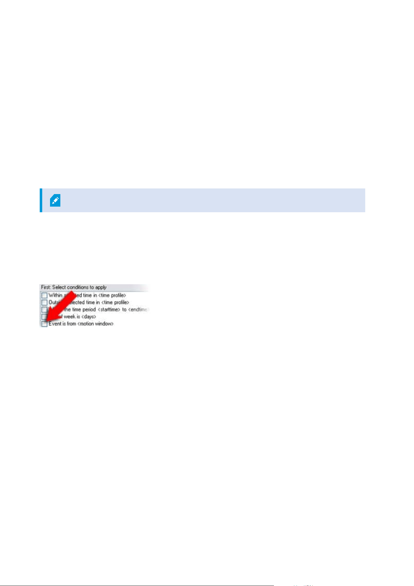
1. In the Overview pane, select a device.
2. Select the Events tab and click Delete.
Specify event properties
You can specify properties for each event you have added. The number of properties depends on the device
and the event. In order for the event to work as intended, you must specify some or all of the properties
identically on the device as well as on the [Events] tab.
Use several instances of an event
To be able to specify different properties for different instances of an event, you can add an event more than
once.
The following example is specific to cameras.
Example: You have configured the camera with two motion windows, called A1, and A2. You have added two
instances of the Motion Started (HW) event. In the properties of one instance, you have specified the use of
motion window A1. In the properties of the other instance, you have specified the use of motion window A2.
When you use the event in a rule, you can specify that the event should be based on motion detected in a
specific motion window for the rule to be triggered:
Devices - Privacy masks
Enable/disable privacy masking
The privacy masking feature is disabled by default.
To enable/disable the privacy masking feature for a camera:
1. In the Site Navigation pane, select Devices.
2. Select the relevant camera device in the Overview pane.
3. On the Privacy masking tab, select or clear Privacy masking check box.
Administrator manual | XProtect® VMS 2023 R1
243 | Configuration
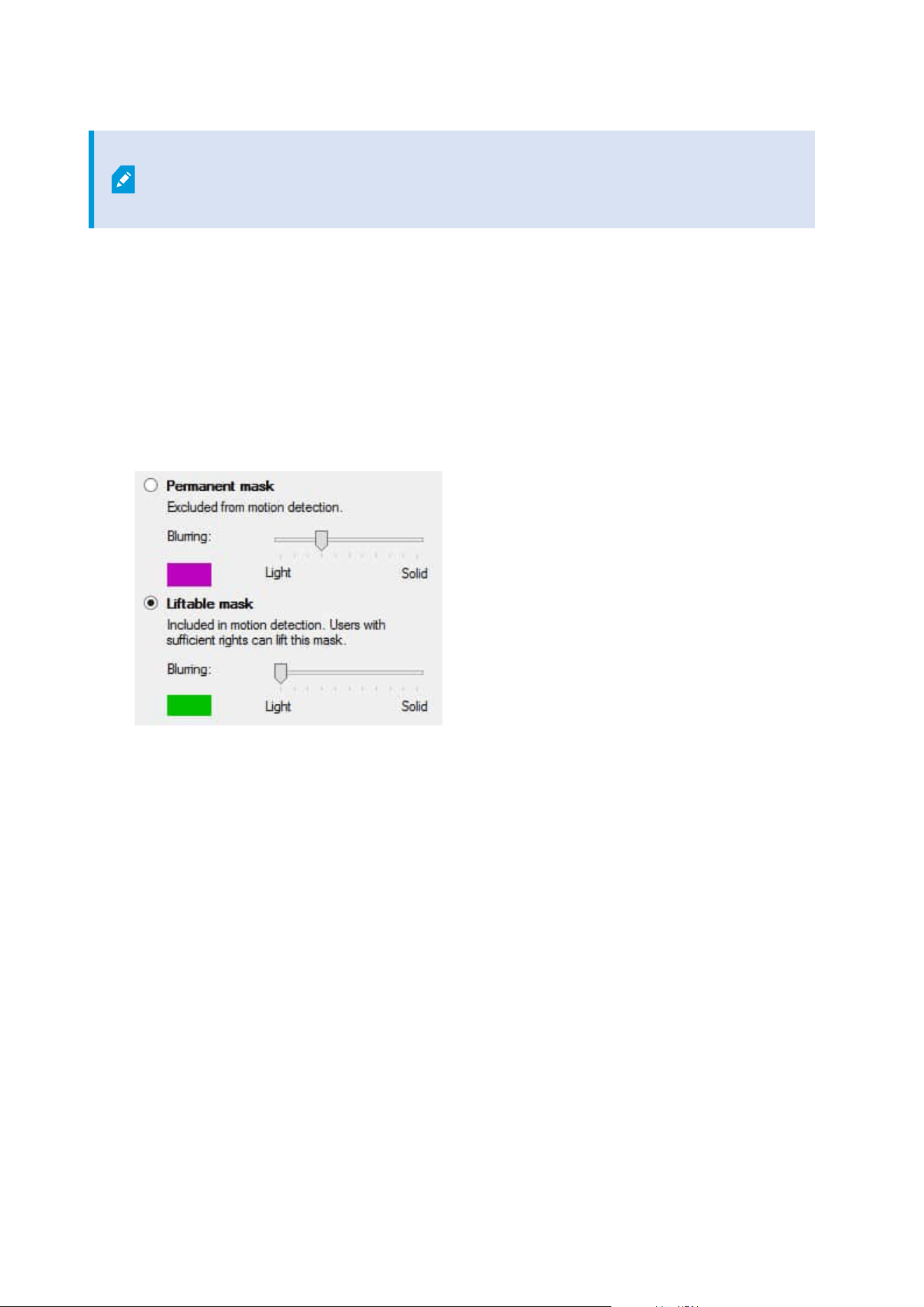
In a Milestone Interconnect setup, the central site disregards privacy masks defined in a
remote site. If you want to apply the same privacy masks, you must redefine it on the
central site.
Define privacy masks
When you enable the privacy masking feature on the Privacy masking tab, a grid is applied to the camera
preview.
1. In the Site Navigation pane, select Devices.
2. Select the relevant camera in the Overview pane.
3. On the Privacy masking tab, to cover an area with a privacy mask, first select Permanent mask or
Liftable mask to define if you want a permanent or liftable privacy mask.
4. Drag the mouse pointer over the preview. Left-click to select a grid cell. Right-click to clear a grid cell.
Administrator manual | XProtect® VMS 2023 R1
244 | Configuration
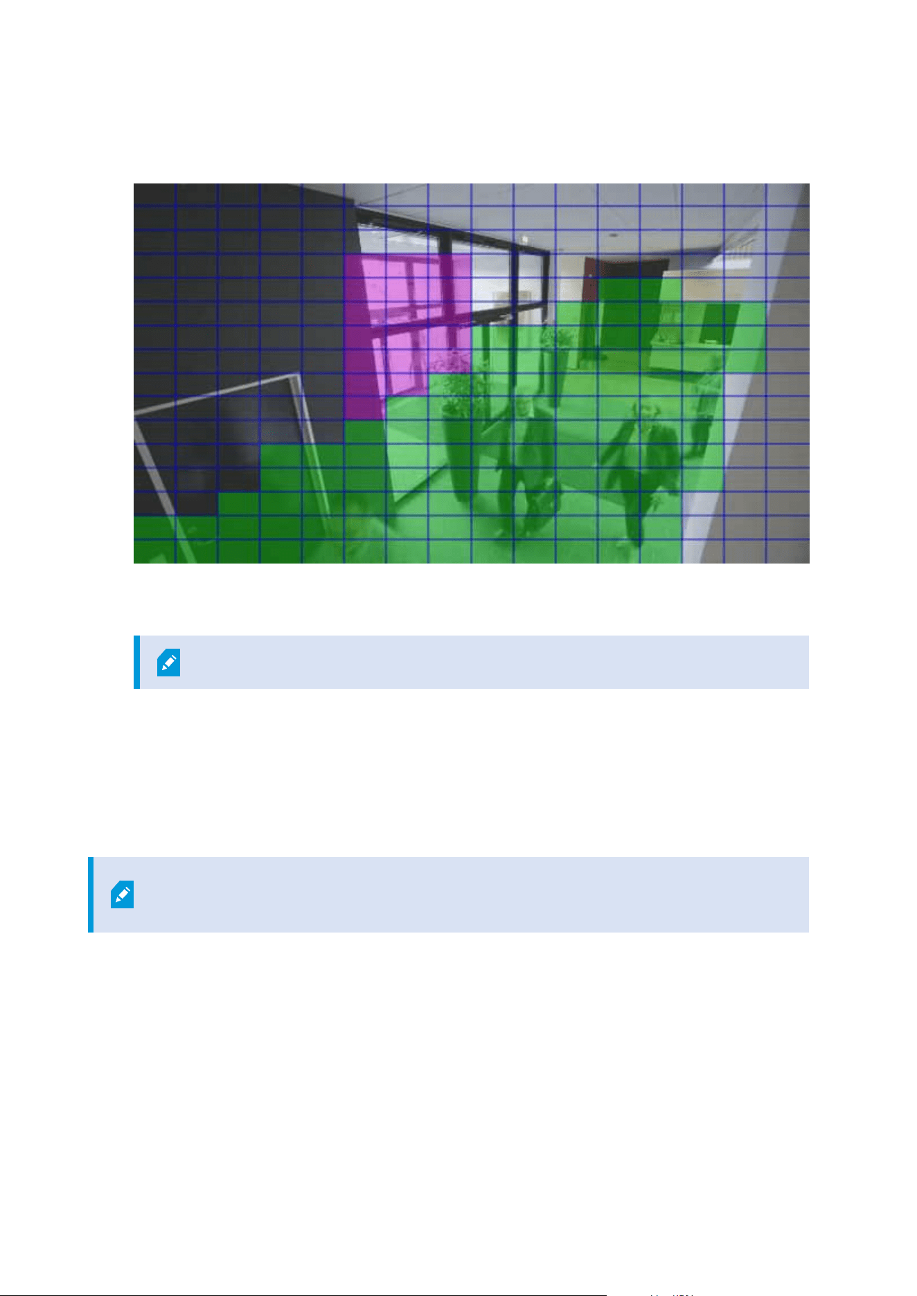
5. You can define as many privacy mask areas as needed. Areas with permanent privacy masks appear in
purple and areas with liftable privacy masks in green.
6. Define how the covering of the areas should appear in the video when shown in the clients. Use the
sliders to go from a light blurring to a full nontransparent mask.
Permanent privacy masks also appear on the Motion tab.
7. In XProtect Smart Client, check that the privacy masks appear as you defined.
Change the timeout for lifted privacy masks
By default, privacy masks are lifted for 30 minutes in XProtect Smart Client and afterwards applied
automatically, but you can change that.
When you change the timeout, remember to do it for the Smart Client profile associated
with the role that has the permission to lift privacy masks.
To change the timeout:
Administrator manual | XProtect® VMS 2023 R1
245 | Configuration
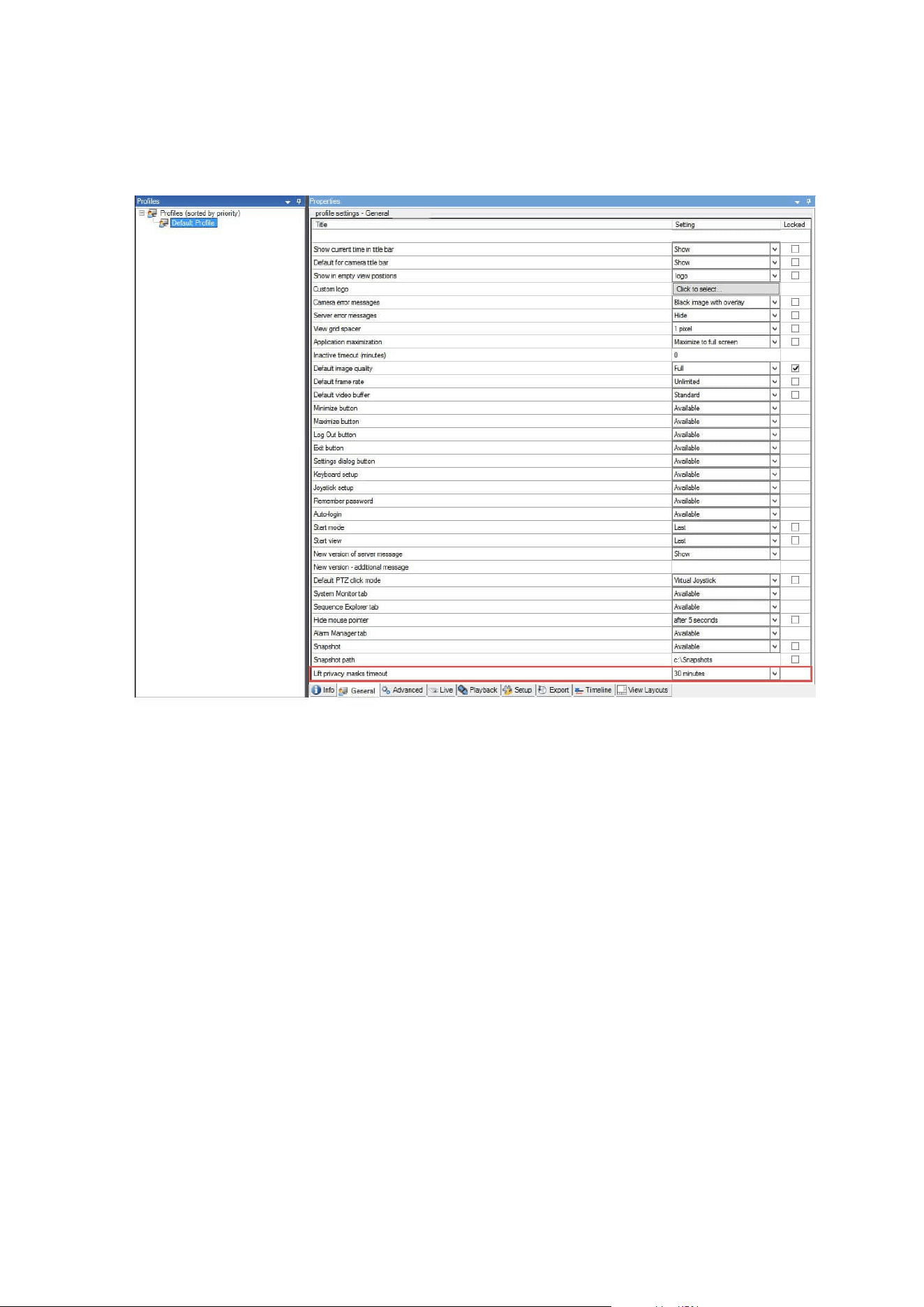
1. Under Smart Client Profiles, select the relevant Smart Client profile.
2. On the General tab, locate Lift privacy masks timeout.
3. Select between the values:
l
2 minutes
l
10 minutes
l
30 minutes
l
1 hour
l
2 hours
l
Until logged out
4. Click Save.
Give users permission to lift privacy masks
By default, no users have permissions to lift privacy masks in XProtect Smart Client.
To enable/disable the permission:
Administrator manual | XProtect® VMS 2023 R1
246 | Configuration
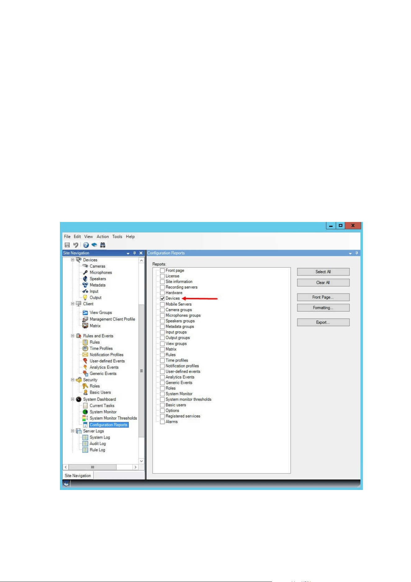
1. In the Site Navigation pane, select Security and then select Roles.
2. Select the role that you want to give permission to lift privacy masks.
3. On the Overall Security tab, select Cameras.
4. Select the Allow check box for the Lift privacy masks permission.
Users that you assign to this role, can lift privacy masks configured as liftable masks for himself/herself as well
as authorize the lift for other XProtect Smart Client users.
Create a report of your privacy masking configuration
The devices report include information about your cameras' current privacy masking settings.
To configure a report:
1. In the Site Navigation pane, select System Dashboard.
2. Under Configuration Reports, select the Devices report.
Administrator manual | XProtect® VMS 2023 R1
247 | Configuration
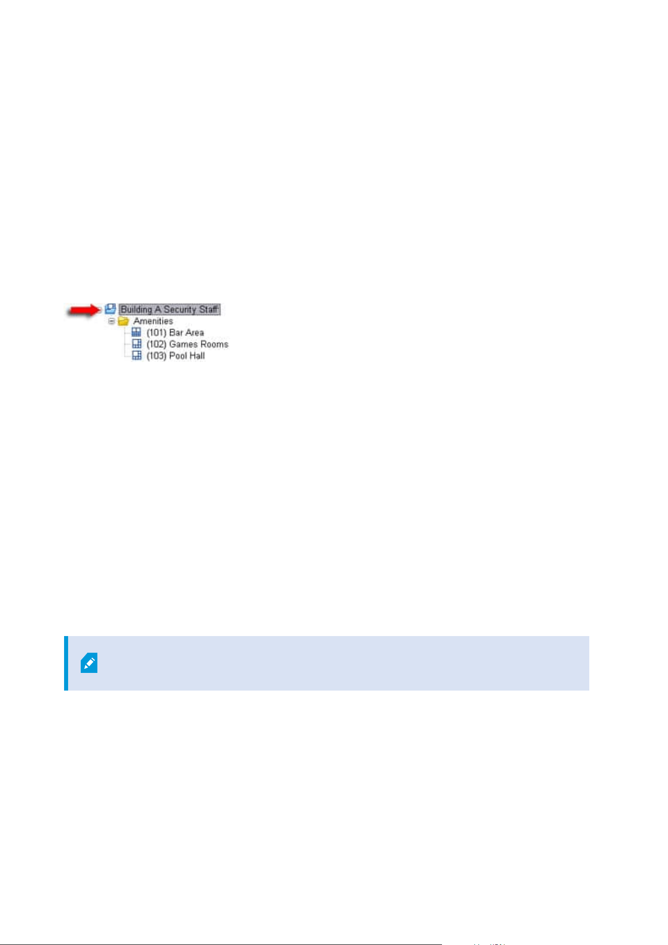
3. If you want to modify the report, you can change the front page and the formatting.
4. Click Export, and the system creates the report as a PDF file.
For more information about reports, see Print a report with your system configuration on page 282.
Clients
View groups (explained)
The way in which the system presents video from one or more cameras in clients is called a view. A view group
is a container for one or more logical groups of such views. In clients, a view group is presented as an
expandable folder from which users can select the group and the view they want to see:
Example from XProtect Smart Client: Arrow indicates a view group, which contains a logical group (called
Amenities), which in turn contains 3 views.
By default, each role you define in the Management Client is also created as a view group. When you add a role
in the Management Client, the role by default appears as a view group for use in clients.
l
You can assign a view group based on a role to users/groups assigned to the relevant role. You may
change these view group permissions by setting this up in the role afterwards
l
A view group based on a role carries the role's name.
Example: If you create a role with the name Building A Security Staff, it appears in XProtect Smart
Client as a view group called Building A Security Staff.
In addition to the view groups, you get when adding roles, you may create as many other view groups
as you like. You can also delete view groups, including those automatically created when adding roles
l
Even if a view group is created each time, you add a role, view groups do not have to correspond to
roles. You can add, rename or remove any of your view groups if required
If you rename a View group, client users already connected must log out and log in
again before the name change is visible.
Add a view group
1. Right-click View Groups, and select Add View Group. This opens the Add View Group dialog box.
2. Enter the name and an optional description of the new view group and click OK.
Administrator manual | XProtect® VMS 2023 R1
248 | Configuration

No roles can use the newly added view group until you have specified such permissions.
If you have specified which roles that can use the newly added view group, client users
that are already connected and who have the relevant roles must log out and log in
again before they can see the view group.
Smart Client profiles
Add and configure a Smart Client profile
You must create a Smart Client profile before you can configure it.
1. Right-click Smart Client Profiles.
2. Select Add Smart Client Profile.
3. In the Add Smart Client Profile dialog box, enter a name and description of the new profile and click OK.
4. In the Overview pane, click the profile you created to configure it.
5. Adjust settings on one, more or all of the available tabs and click OK.
Copy a Smart Client profile
If you have a Smart Client profile with complicated settings or permissions and need a similar profile, it might
be easier to copy an already existing profile and make minor adjustments to the copy than to creating a new
profile from scratch.
1. Click Smart Client Profiles, right-click the profile in the Overview pane, select Copy Smart Client
Profile.
2. In the dialog box that appears, give the copied profile a new unique name and description. Click OK.
3. In the Overview pane, click the profile you just created to configure it. This is done by adjusting settings
on one, more, or all of the available tabs. Click OK.
Create and set up Smart Client profiles, roles and time profiles
When you work with Smart Client profiles, it is important to understand the interaction between Smart Client
profiles, roles and time profiles:
l
Smart Client profiles deal with user permission settings in XProtect Smart Client
l
Roles deal with security settings in clients, MIP SDK and more
l
Time profiles deal with time aspects of the two profiles-types
Together these three features provide unique control and customizing possibilities with regards to XProtect
Smart Client user permissions.
Administrator manual | XProtect® VMS 2023 R1
249 | Configuration

Example: You need a user in your XProtect Smart Client setup who should only be allowed to view live video
(no playback) from selected cameras, and only during normal working hours (8.00 to 16.00). One way of setting
this up could be as follows:
1. Create a Smart Client profile, and name it, for example, Live only.
2. Specify the needed live/playback settings on Live only.
3. Create a time profile, and name it, for example, Daytime only.
4. Specify the needed time period on Daytime only.
5. Create a new role and name it, for example, Guard (Selected cameras).
6. Specify which cameras Guard (Selected cameras) can use.
7. Assign the Live only Smart Client profile and the Daytime only time profile to the Guard (Selected
cameras) role to connect the three elements.
You now have a mix of the three features creating the wanted result and allowing you room for easy fine-
tuning and adjustments. You can do the setup in a different order, for example, creating the role first and then
the Smart Client profile and the time profile, or any other order you prefer.
Set number of cameras allowed during search
You can configure how many cameras the operators can add to a search in XProtect Smart Client. The default
value is 100. If exceeding the camera limit, the operator receives a warning.
Administrator manual | XProtect® VMS 2023 R1
250 | Configuration

1. In XProtect Management Client, expand Client > Smart Client Profiles.
2. Select the relevant profile.
Administrator manual | XProtect® VMS 2023 R1
251 | Configuration

3. Click the General tab.
Administrator manual | XProtect® VMS 2023 R1
252 | Configuration
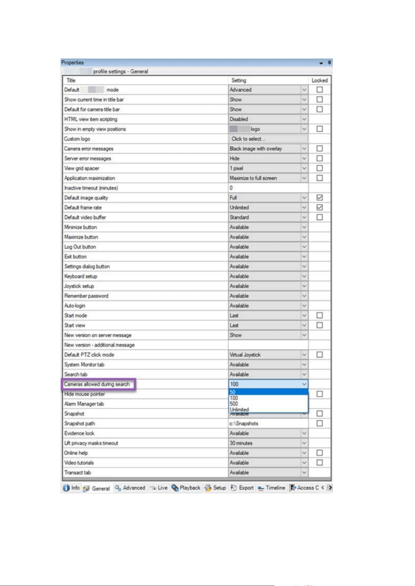
Administrator manual | XProtect® VMS 2023 R1
253 | Configuration

4. In the Cameras allowed during search, select one of these values:
l
50
l
100
l
500
l
Unrestricted
5. Save your changes.
Change the default export settings
When you install your XProtect VMSsystem, the default export settings that define the export options in
XProtect Smart Client are restricted to ensure the highest level of security. You can change these settings to
give operators more options.
Default settings
l
Only the XProtect format is available
l
Re-export is prevented
l
Exports are password-protected
l
256-bit AESencryption
l
Digital signatures are added
l
Not possible to export to MKV format or AVI format
l
Not possible to export still images
Steps:
Administrator manual | XProtect® VMS 2023 R1
254 | Configuration
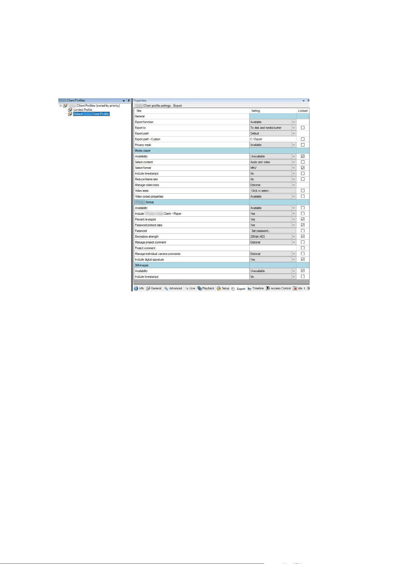
1. In XProtect Management Client, expand Client > Smart Client Profiles.
2. Select Default Smart Client Profile.
3. In the Properties pane, select the Export tab.
4. To make a restricted format available in XProtect Smart Client, find the setting and select Available.
5. To enable operators to change a setting in XProtect Smart Client, clear the Locked check box next to the
relevant setting.
6. If relevant, change other settings.
7. (optional) Log in to XProtect Smart Client to verify that your settings have been applied.
Management Client profiles
Add and configure a Management Client profile
If you do not want to use the default profile, you can create a Management Client profile before you can
configure it.
Administrator manual | XProtect® VMS 2023 R1
255 | Configuration

1. Right-click Management Client Profiles.
2. Select Add Management Client Profile.
3. In the Add Management Client Profile dialog box, enter a name and description of the new profile and
click OK.
4. In the Overview pane, click the profile you created to configure it.
5. On the Profile tab, select or clear functionality from the Management Client profile.
Copy a Management Client profile
If you have a Management Client profile with settings that you would like to reuse, you can copy an already
existing profile and make minor adjustments to the copy instead of creating a new profile from scratch.
1. Click Management Client Profile, right-click the profile in the Overview pane, select Copy
Management Client Profile.
2. In the dialog box that appears, give the copied profile a new unique name and description. Click OK.
3. In the Overview pane, click the profile and go to the Info tab or Profile tab to configure the profile.
Manage the visibility of functionality for a Management Client profile
Associate Management Client profiles with roles to limit the user interface to represent the functionality
available for each administrator role.
Associate a Management Client profile with a role
1. Expand the Security node and click Roles.
2. On the Info tab in the Role Settings window, associate a profile with a role. For more information, see
Info tab (roles).
Manage the overall access to system functionality for a role
Management Client profiles only handle the visual representation of system functionality, not the actual access
to it.
To manage the overall access to system functionality for a role:
1. Expand the Security node and click Roles.
2. Click the Overall Security tab and select the appropriate check boxes. For more information, see
Overall Security tab (roles) on page 495.
On the Overall Security tab, make sure to enable the Connect security permission in
order to grant all roles access to the Management Server.
Administrator manual | XProtect® VMS 2023 R1
256 | Configuration
Apart from the built-in administrator role, only users associated with a role that has
been granted Manage security permissions for the management server on the Overall
Security tab, can add, edit, and delete Management Client profiles.
Limit visibility of functionality for a profile
You can change settings for the visibility of all Management Client elements. By default,
the Management Client profile can see all functionality in the Management Client.
1. Expand the Client node and click Management Client Profiles.
2. Select a profile and click the Profile tab.
3. Clear the check boxes for the relevant functionality in order to remove the functionality visually from
the Management Client for any Management Client user with a role associated with this Management
Client profile.
Matrix
Matrix and Matrix recipients (explained)
Matrix is a feature for distributing video remotely.
A Matrix recipient is a computer with XProtect Smart Client, that is defined as a Matrix recipient in
Management Client.
If you use Matrix, you can push video from any camera on your system's network to any running Matrix
recipient.
To see a list of Matrix recipients added in the Management Client, expand Client in the Site Navigation pane,
then select Matrix. A list of Matrix configurations is displayed in the Properties pane.
In Management Client, you must add each Matrix recipient must be added to receive
Matrix-triggered video.
Define rules sending video to Matrix-recipients
To send video to Matrix-recipients you must include the Matrix recipient in a rule that triggers the video
transmission to the related Matrix-recipient. To do so:
1. In the Site Navigation pane, expand Rules and Events > Rules. Right-click Rules to open the Manage
Rule wizard. In the first step, select a rule type and in the second step, a condition.
2. In Manage Rule's step 3 (Step 3: Actions) select the Set Matrix to view <devices> action.
Administrator manual | XProtect® VMS 2023 R1
257 | Configuration

3. Click the Matrix link in the initial rule description.
4. In the Select Matrix Configuration dialog box, select the relevant Matrix-recipient, and click OK.
5. Click the devices link in the initial rule description and select from which cameras you would like to send
video to the Matrix-recipient, then click OK to confirm your selection.
6. Click Finish if the rule is complete or define if required additional actions and/or a stop action.
If you delete a Matrix-recipient, any rule that includes the Matrix-recipient stops
working.
Add Matrix recipients
To add an existing Matrix recipient in Management Client:
1. Expand Clients, then select Matrix.
2. Right-click Matrix Configurations and select Add Matrix.
3. Fill out the fields in the Add Matrix dialog box.
1. In the Address field enter the IP address or the host name of the required Matrix recipient.
2. In the Port field enter the port number used by the Matrix recipient installation.
4. Click OK.
You can now use the Matrix recipient in rules.
Your system does not verify that the specified port number or password is correct or
that the specified port number, password, or type corresponds with the actual Matrix
recipient. Make sure that you enter the correct information.
Send the same video to several XProtect Smart Client views
You can send the same video to Matrix positions in several of the XProtect Smart Client views, provided the
Matrix positions of the views share the same port number and password:
1. In XProtect Smart Client, create the relevant views and Matrix positions that share the same port
number and password.
2. In the Management Client, add the relevant XProtect Smart Client as a Matrix-recipient.
3. You may include the Matrix-recipient in a rule.
Administrator manual | XProtect® VMS 2023 R1
258 | Configuration
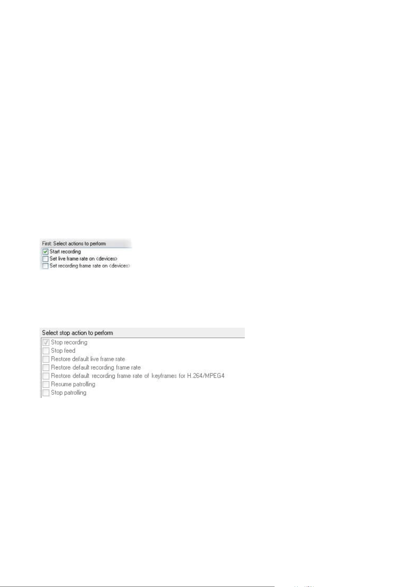
Rules and events
Add rules
When you add rules, you are guided by the wizard Manage Rule which only lists relevant options.
It ensures that required elements are not missing from a rule. Based on your rule's content, it automatically
suggests suitable stop actions, that is what should take place when the rule no longer applies, ensuring that
you do not unintentionally create a never-ending rule.
Events
When you add an event-based rule, you can select different types of events.
l
See Events overview to get an overview and a description of the event types that you can select.
Actions and stop actions
When you add rules, you can select different actions.
Some of the actions require a stop action. For example, if you select the action Start recording, recording
starts and potentially continues indefinitely. As a result, the action Start recording has a mandatory stop
action called Stop recording.
The Manage Rule wizard makes sure you specify stop actions when necessary:
Selecting stop actions. In the example, note the mandatory stop action (selected, dimmed), the non-relevant
stop actions (dimmed) and the optional stop actions (selectable).
l
See Actions and stop actions for an overview of start and stop actions that you can select.
Create a rule
1. Right-click the Rules item > Add Rule. This opens the Manage Rule wizard. The wizard guides you
through specifying the content of your rule.
2. Specify a name and a description of the new rule in the Name and Description fields respectively.
Administrator manual | XProtect® VMS 2023 R1
259 | Configuration
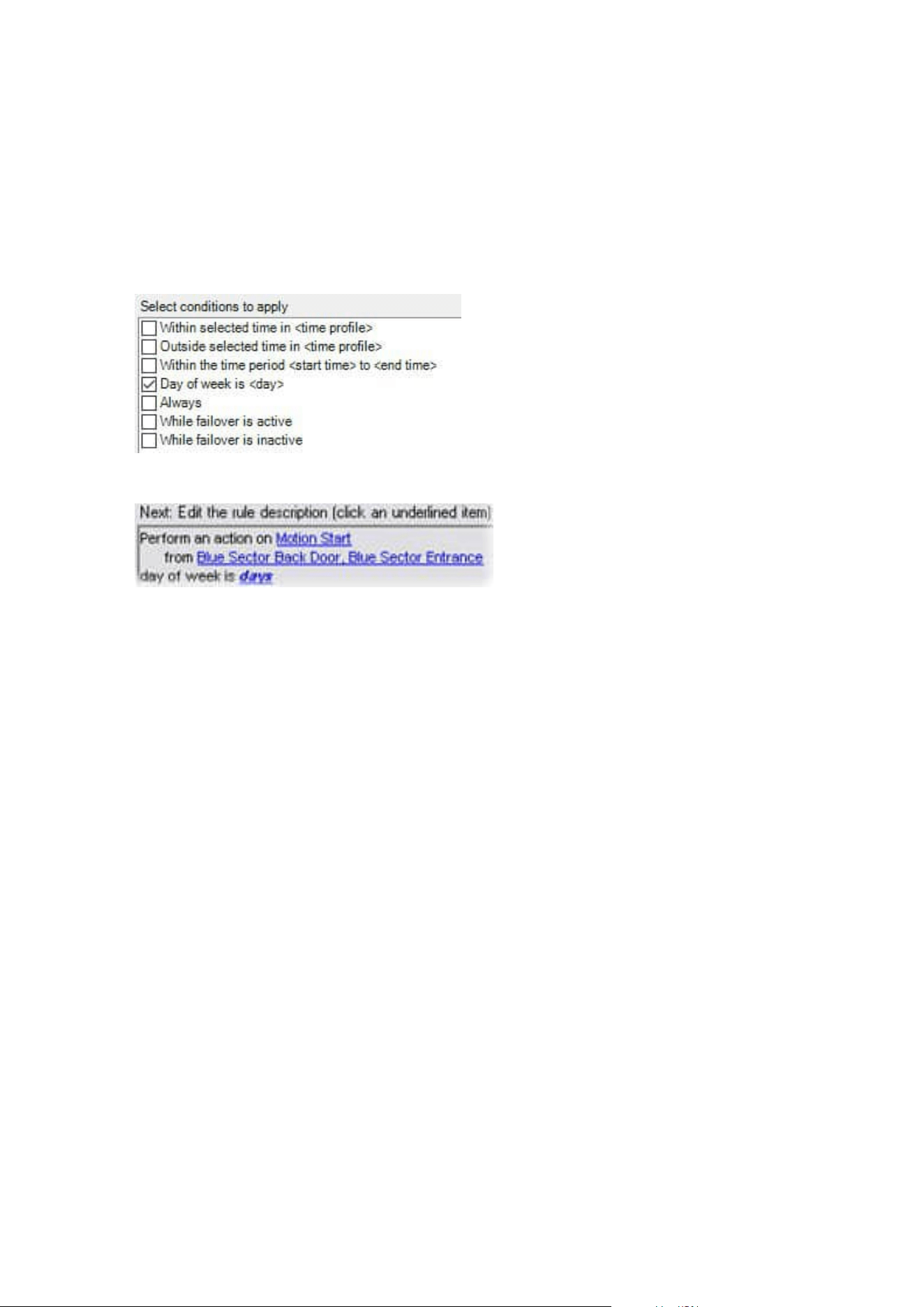
3. Select the relevant type of condition for the rule: either a rule which performs one or more actions
when a particular event occurs, or a rule which performs one or more actions when you enter a specific
period of time.
4. Click Next to go to the wizard's second step. On the wizard's second step, define further conditions for
the rule.
5. Select one or more conditions, for example Day of week is <day>:
Depending on your selections, edit the rule description in the lower part of the wizard window:
Click the underlined items in bold italics to specify their exact content. For example, clicking the days
link in our example lets you select one or more days of the week on which the rule should apply.
6. Having specified your exact conditions, click Next to move to the next step of the wizard and select
which actions the rule should cover. Depending on the content and complexity of your rule, you may
need to define more steps, such as stop events and stop actions. For example, if a rule specifies that a
device should perform a particular action during a time interval (for example, Thursday between 08.00
and 10.30), the wizard may ask you to specify what should happen when that time interval ends.
7. Your rule is by default active once you have created it if the rule's conditions are met. If you do not want
the rule to be active straight away, clear the Active check box.
8. Click Finish.
Validate rules
You can validate the content of an individual rule or all rules in one go. When you create a rule, the Manage
Rule wizard ensures that all of the rule's elements are valid.
When a rule has existed for some time, one or more of the rule's elements may have been affected by other
configuration, and the rule may no longer work. For example, if a rule is triggered by a particular time profile,
the rule does not work if you have deleted that time profile or if you no longer have permissions to it. Such
unintended effects of configuration may be hard to keep an overview of.
Administrator manual | XProtect® VMS 2023 R1
260 | Configuration
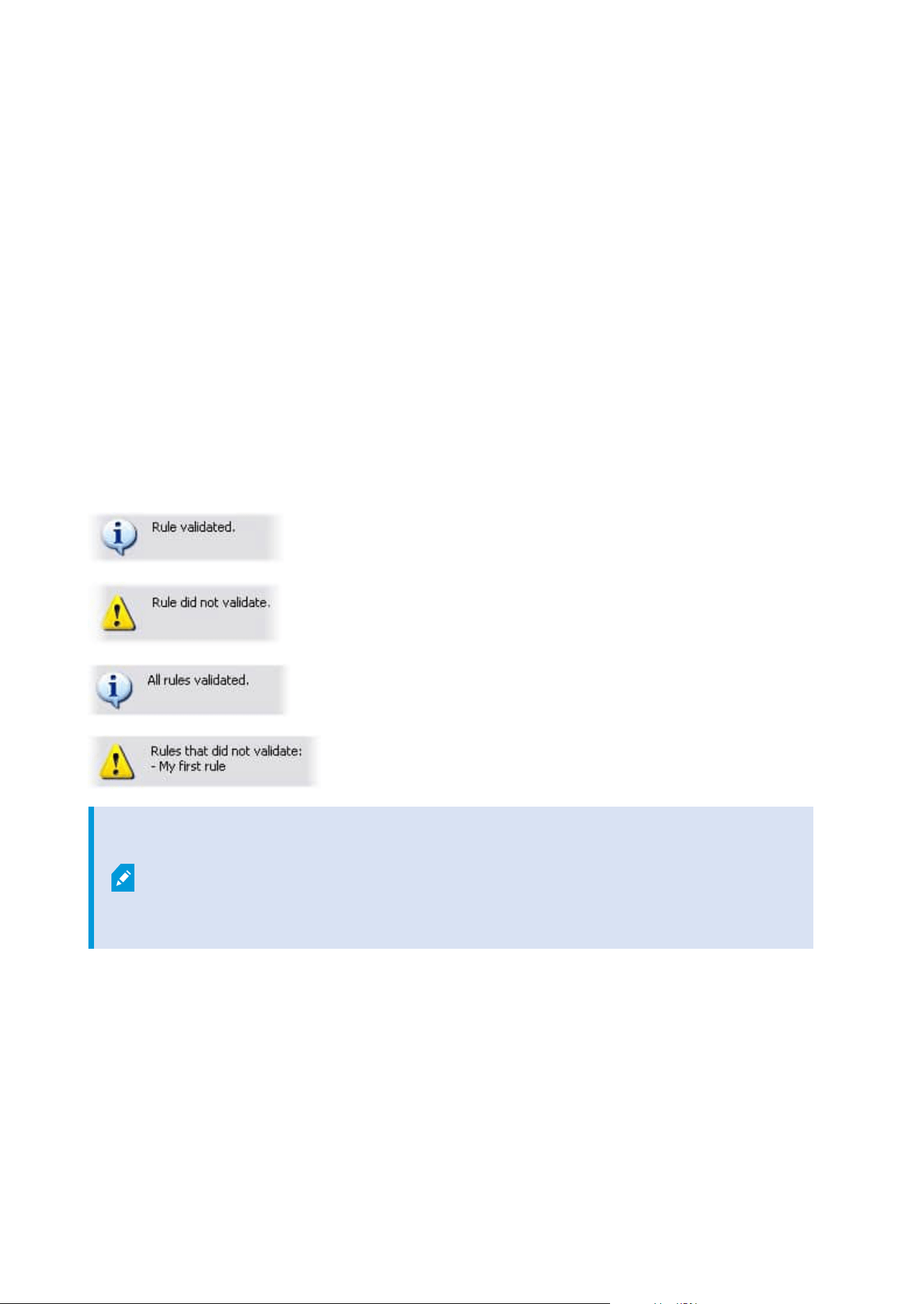
Rule validation helps you keep track of which rules have been affected. Validation takes place on a per-rule
basis and each rule is validated by themselves. You cannot validate rules against each other, for example in
order to see whether one rule conflicts with another rule, not even if you use the Validate All Rules feature.
Validate a rule
1. Click Rules and select the rule you want to validate.
2. Right-click the rule and click Validate Rule.
3. Click OK.
Validate all rules
1. Right-click the Rules item and then click Validate All Rules. .
2. Click OK.
A dialog box informs you whether the rule(s) validated successfully or not. If you chose to validate more than
one rule and one or more rules did not succeed, the dialog box lists the names of the affected rules.
You cannot validate whether configuration of requirements outside the rule itself may
prevent the rule from working. For example, a rule specifying that recording should take
place when motion is detected by a particular camera is validated if the elements in the
rule itself are correct, even if motion detection, which is enabled on a camera level, not
through rules, has not been enabled for the relevant camera.
Edit, copy and rename a rule
1. In the Overview pane, right-click the relevant rule.
2. Select either:
Edit Rule or Copy Rule or Rename Rule. The wizard Manage Rule opens.
Administrator manual | XProtect® VMS 2023 R1
261 | Configuration
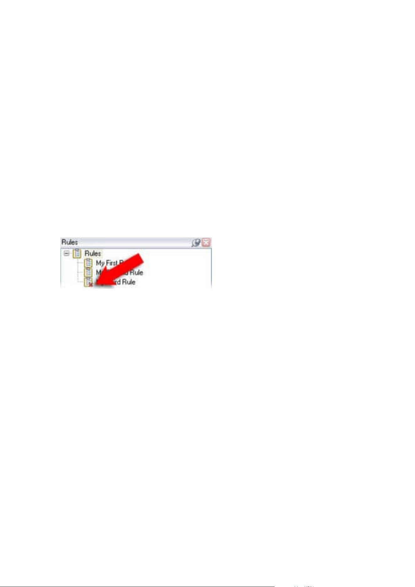
3. If you select Copy Rule, the wizard opens displaying a copy of the selected rule. Click Finish to create a
copy.
4. If you select Edit Rule, the wizard opens and you can enter changes. Click Finish to accept the changes.
5. If you select Rename Rule, you can rename the rule name text directly.
Deactivate and activate a rule
Your system applies a rule as soon as the rule's conditions apply which means it is active. If you do not want a
rule to be active, you can deactivate the rule. When you deactivate the rule, the system does not apply the rule
even if the rule's conditions apply. You can easily activate a deactivated rule later.
Deactivating a rule
1. In the Overview pane, select the rule.
2. Clear the Active check box in the Properties pane.
3. Click Save in the toolbar.
4. An icon with a red x indicates that the rule is deactivated in the Rules list:
Activating a rule
When you want to activate the rule again, select the rule, select the Activate check box, and save the setting.
Specify a time profile
1. In the Time Profiles list, right-click Time Profiles > Add Time Profile. This opens the Time Profile
window.
2. In the Time Profile window, enter a name for the new time profile in the Name field. Optionally, enter a
description of the new time profile in the Description field.
3. In the Time Profile window's calendar, select either Day View, Week View or Month View, then right-
click inside the calendar and select either Add Single Time or Add Recurring Time.
4. When you have specified the time periods for your time profile, click OK in the Time Profile window.
Your system adds your new time profile to the Time Profiles list. If at a later stage you wish to edit or
delete the time profile, you do that from the Time Profiles list as well.
Add a single time
When you select Add Single Time, the Select Time window appears:
Administrator manual | XProtect® VMS 2023 R1
262 | Configuration
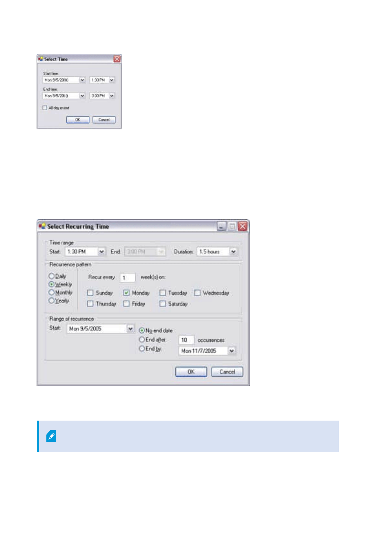
Time and date format may be different on your system.
1. In the Select Time window, specify Start time and End time. If the time is to cover whole days, select
the All day event box.
2. Click OK.
Add a recurring time
When you select Add Recurring Time, the Select Recurring Time window appears:
1. In the Select Time window, specify time range, recurrence pattern and range of recurrence.
2. Click OK.
A time profile can contain several periods of time. If you want your time profile to
contain further periods of time, add more single times or recurring times.
Administrator manual | XProtect® VMS 2023 R1
263 | Configuration
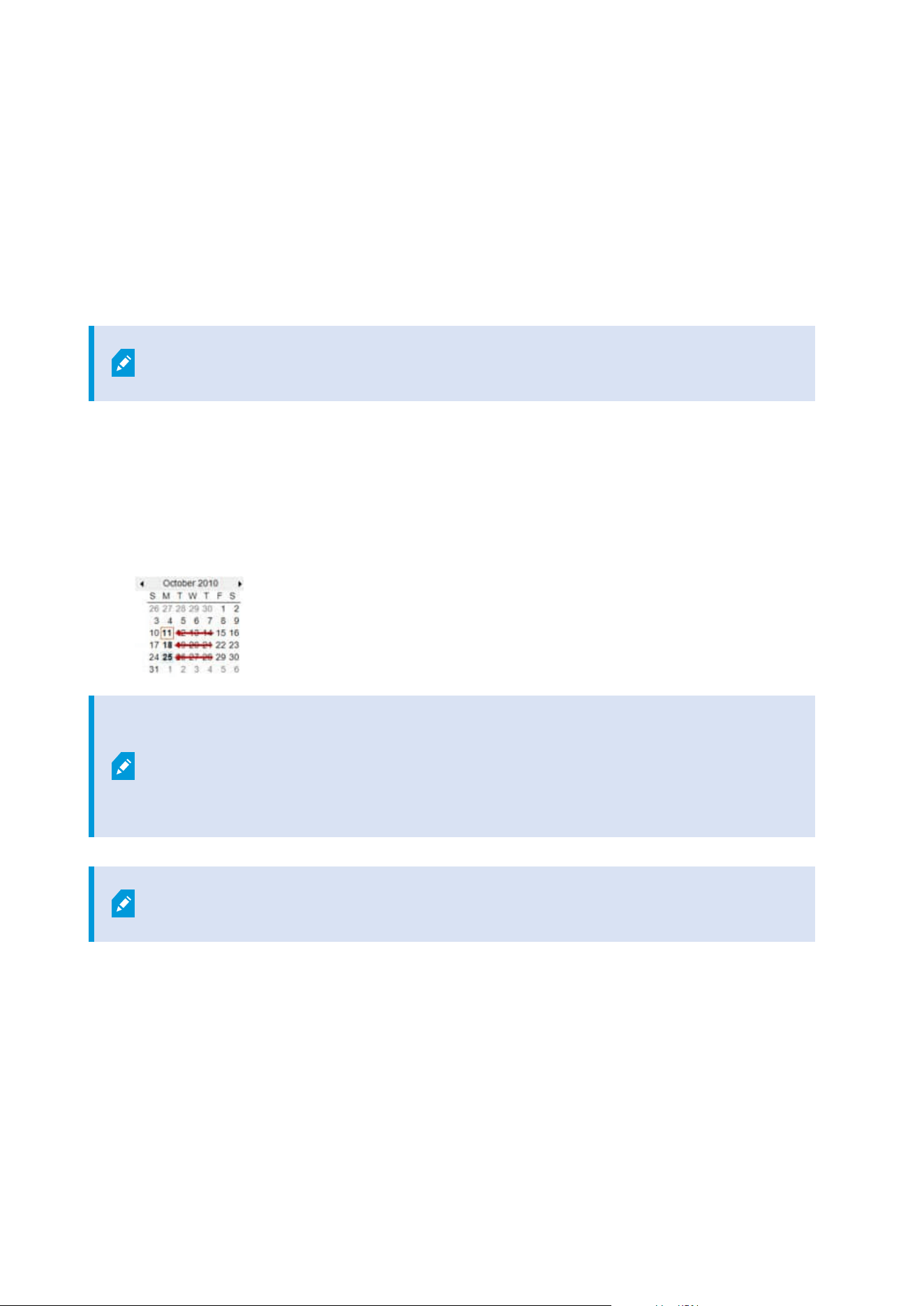
Recurring time
When you set an action to be executed on a detailed, recurring schedule.
For example:
l
Every week on Tuesday every 1 hour(s) between 15:00 and 15:30
l
On day 15 every 3 month(s) at 11:45
l
Every day every 1 hour(s) between 15:00 and 19:00
The time is based on the local time settings of the server on which Management Client is
installed.
Edit a time profile
1. In the Overview pane's Time Profiles list, right-click the relevant time profile, and select Edit Time
Profile. This opens the Time Profile window.
2. Edit the time profile as needed. If you have made changes to the time profile, click OK in the Time
Profile window. You return to the Time Profiles list.
In the Time Profile Information window, you can edit the time profile as needed.
Remember that a time profile may contain more than one time period, and that time
periods may be recurring. The small month overview in the top right corner can help you
get a quick overview of the time periods covered by the time profile, as dates containing
specified times are highlighted in bold.
In this example, the bold dates indicate that you have specified time periods on several
days, and that you have specified a recurring time on Mondays.
Administrator manual | XProtect® VMS 2023 R1
264 | Configuration
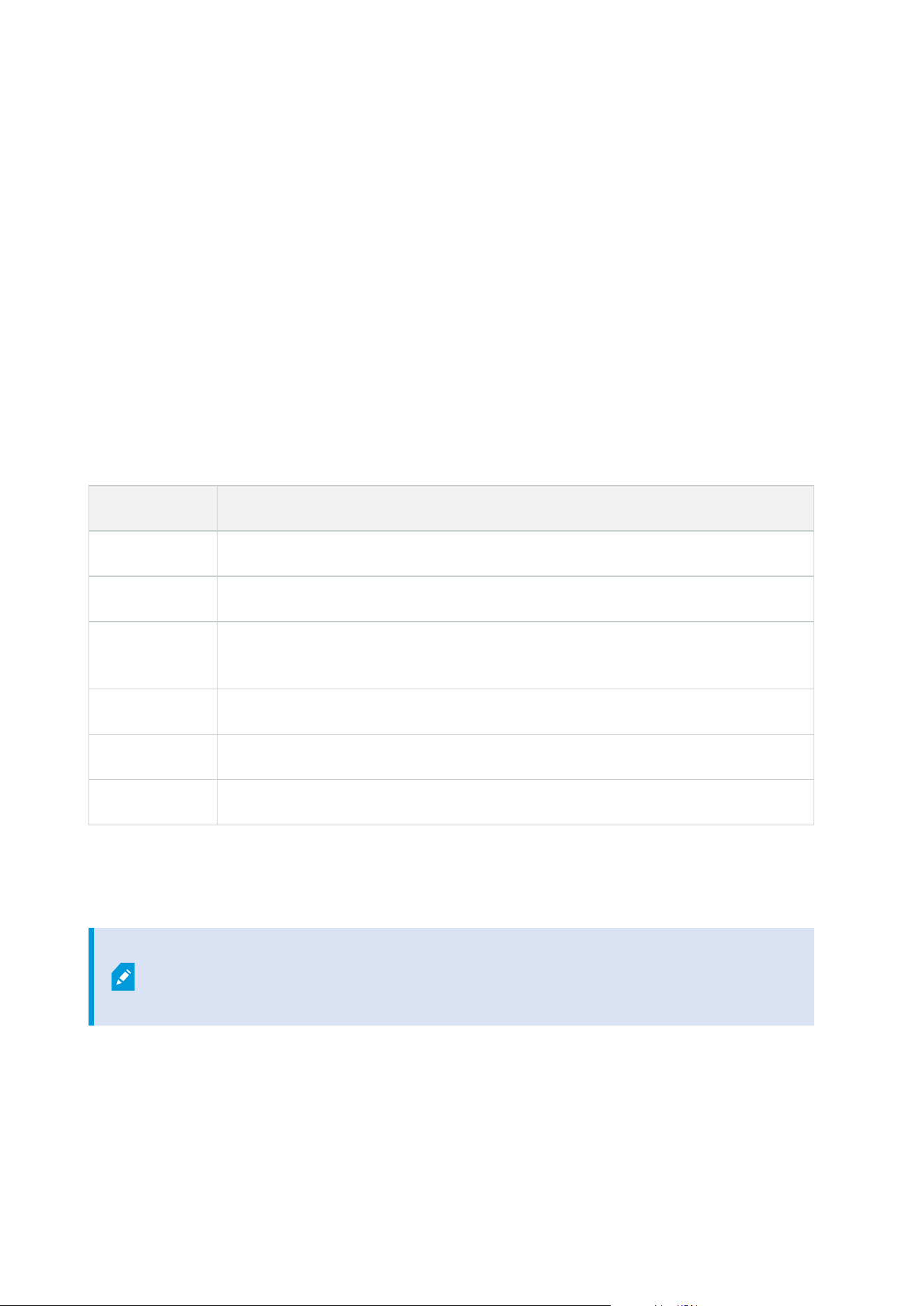
Create day length time profiles
1. Expand the Rules and Events folder > Time Profiles.
2. In the Time Profiles list, right-click Time Profiles, and select Add Day Length Time Profile.
3. In the Day Length Time Profile window, refer to the properties table below to fill in the needed
information. To deal with transition periods between lightness and darkness, you can offset activation
and deactivation of the profile. The time and the name of months are shown in the language used your
computer's language/regional settings.
4. To see the location of the entered geographic coordinates in a map, click Show Position in Browser.
This opens a browser where you can see the location.
5. Click OK.
Day length time profile properties
Name Description
Name The name of the profile.
Description A description of the profile (optional).
Geo
coordinates
Geographic coordinates indicating the physical location of the camera(s) assigned to
the profile.
Sunrise offset Number of minutes (+/-) by which activation of the profile is offset by sunrise.
Sunset offset Number of minutes (+/-) by which deactivation of the profile is offset by sunset.
Time zone Time zone indicating the physical location of the camera(s).
Add notification profiles
Before you can create notification profiles, you must specify mail server settings for
email notifications. For more information, see Requirements for creating notification
profiles.
Administrator manual | XProtect® VMS 2023 R1
265 | Configuration
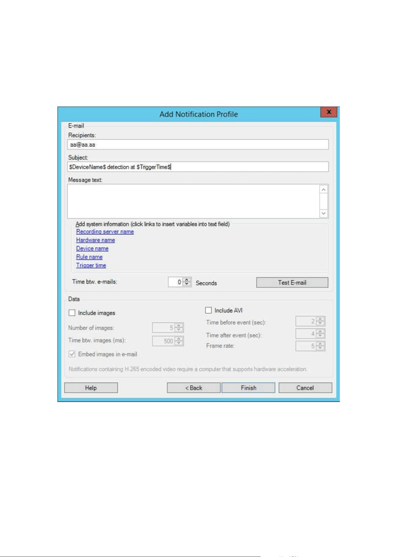
1. Expand Rules and Events, right-click Notification Profiles > Add Notification Profile. This opens the
Add Notification Profile wizard.
2. Specify name and description. Click Next.
3. Specify recipient, subject, message text and time between emails:
4. To send a test email notification to the specified recipients, click Test E-mail.
5. To include pre-alarm still images, select Include images, and specify number of images, time between
images and whether to embed images in emails or not.
6. To include AVI video clips, select Include AVI, and specify the time before and after event and frame
rate.
Administrator manual | XProtect® VMS 2023 R1
266 | Configuration
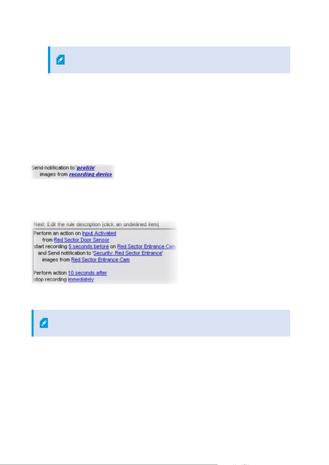
Notifications containing H.265 encoded video require a computer that supports
hardware acceleration.
7. Click Finish.
Trigger email notifications from rules
1. Right-click the Rules item, and then click > Add Rule or Edit rule.
2. In the Manage Rule wizard, click Next to go to the Select actions to perform list and select Send
notification to <profile>.
3. Select the relevant notification profile and select the cameras that recordings to include in the
notification profile's email notifications should come from.
You cannot include recordings in the notification profile's email notifications unless something is actually being
recorded. If you want still images or AVI video clips in the email notifications, verify that the rule specifies that
recording should take place. The following example is from a rule which includes both a Start recording action
and a Send notification to action:
Add a user-defined event
No matter how you want to use user-defined events, you must add each user-defined
event through the Management Client.
1. Expand Rules and Events > User-defined Events.
2. In the Overview pane, right-click Events > Add User-defined Event.
3. Enter a name for the new user-defined event, and click OK. The newly added user-defined event now
appears in the list in the Overview pane.
Administrator manual | XProtect® VMS 2023 R1
267 | Configuration

The user can now trigger the user-defined event manually in XProtect Smart Client if the user has permissions
to do so.
If you delete a user-defined event, this affects any rules in which the user-defined event
is in use. Also, a deleted user-defined event only disappears from XProtect Smart Client
when the XProtect Smart Client users log out.
Rename a user defined event
If you rename a user-defined event, already connected XProtect Smart Client users must
log out and log in again before the name change is visible.
1. Expand Rules and Events > User-defined Events.
2. In the Overview pane, select the user-defined event.
3. In the Properties pane, overwrite the existing name.
4. In the toolbar, click Save.
Add and edit an analytics event
Add an analytics event
1. Expand Rules and Events, right-click Analytics Events and select Add New.
2. In the Properties window, enter a name for the event in the Name field.
3. Enter a description text in the Description field if needed.
4. In the toolbar, click Save. You can test the validity of the event by clicking Test Event. You can
continually correct errors indicated in the test and run the test as many times as you want and from
anywhere in the process.
Edit an analytics event
1. Click an existing analytics event to view the Properties window, where you can edit relevant fields.
2. You can test the validity of the event by clicking Test Event. You can continually correct errors indicated
in the test and run the test as many times as you want and from anywhere in the process.
Edit analytics events settings
In the toolbar, go to the Tools > Options > Analytics Events tab to edit relevant settings.
Administrator manual | XProtect® VMS 2023 R1
268 | Configuration
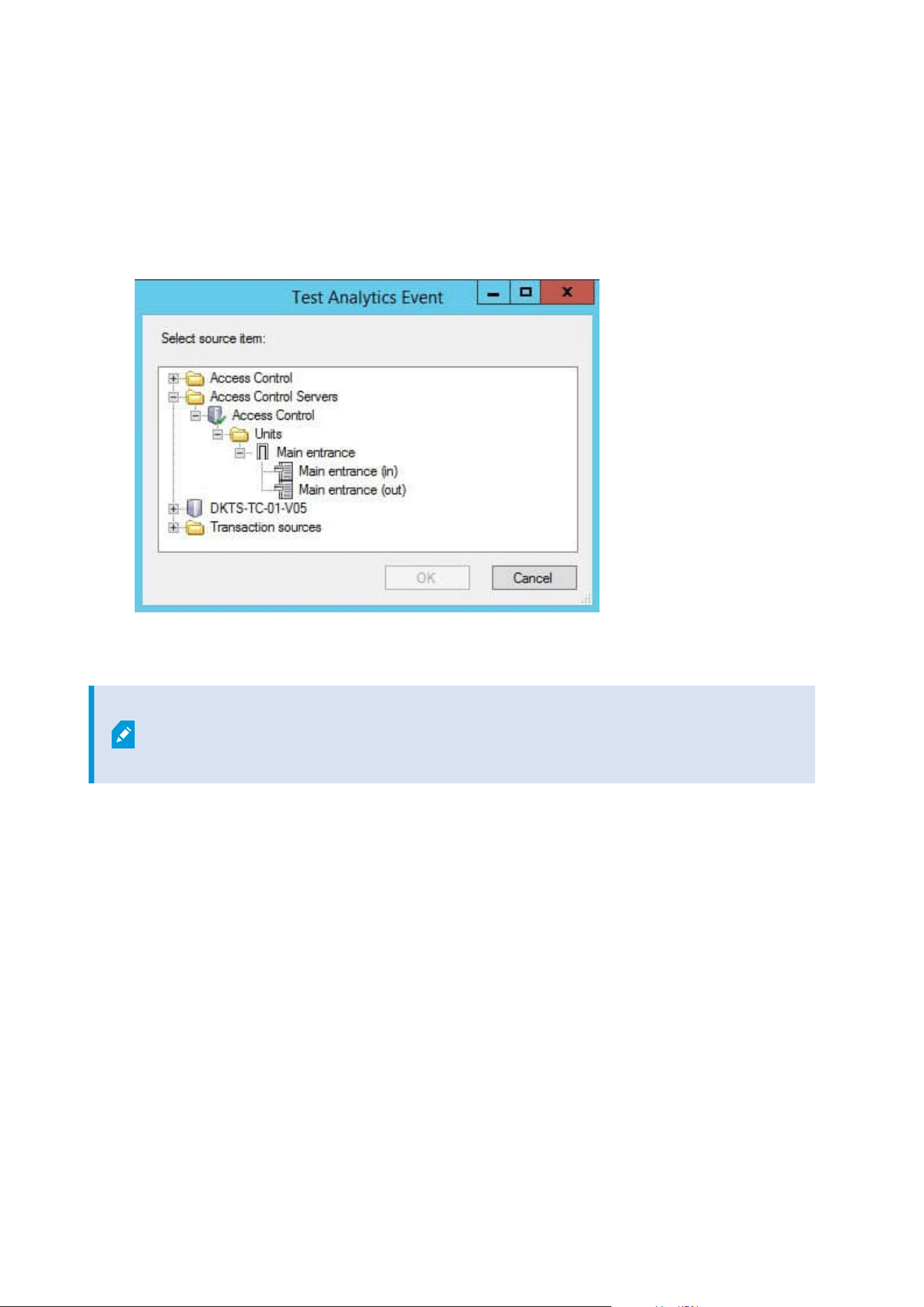
Test an analytics event
After you create an analytics event, you can test the requirements (see Test an analytics event on page 269), for
example that the analytics events feature has been enabled in Management Client.
1. Select an existing analytics event.
2. Intheproperties,clicktheTestEventbutton.Awindowappearsthatshowsallthepossiblesourcesofevents.
3. Select the source of your test event, for example a camera. The window is closed and a new window
appears that goes through four conditions that must be fulfilled for the analytics event to work.
As an additional test, in XProtect Smart Client you can verify that the analytics event was
sent to the event server. To do this, open XProtect Smart Client and view the event in the
Alarm Manager tab.
Add a generic event
You can define generic events to help the VMS recognize specific strings in TCP or UDP packets from an
external system. Based on a generic event, you can configure Management Client to trigger actions, for
example to start recording, or alarms.
Requirements
You have enabled generic events and specified the source destinations allowed. For more information, see
Generic Events tab (options) on page 381.
Administrator manual | XProtect® VMS 2023 R1
269 | Configuration

To add a generic event:
1. Expand Rules and Events.
2. Right-click Generic Events and select Add New.
3. Fill in the needed information and properties. For more information, see Generic Events and Data
sources (properties) on page 488.
4. (optional) To validate that the search expression is valid, enter a search string in the Check if
expression matches event string field that corresponds to the expected packages:
l
Match - the string can be validated against the search expression
l
No match - the search expression is invalid. Change it and try again
In XProtect Smart Client, you can verify whether your generic events have been received
by the event server. You do this in the Alarm List on the Alarm Manager tab by
selecting Events.
Authentication
Register claims from an external IDP
1. In Management Client, select Tools > Options and open the External IDP tab.
2. In the External IDP section, select Add.
3. In the Registered claims section, select Add.
4. Enter the information about the claim. For more information, see Register claims.
Map claims from an external IDP to roles in XProtect
On the external IDP site, the administrator must create claims consisting of a name and a value. Subsequently,
the claim is mapped to a role in the VMS, and the user's privileges will be determined by the role.
1. From the Site Navigation pane in Management Client, expand the Security node and select Roles.
2. Select a role, select the External IDP tab, and select Add.
3. Select an external IDP and a claim name and enter a claim value.
The claim name must be written exactly as the claim name coming from the
external IDP.
4. Select OK.
Administrator manual | XProtect® VMS 2023 R1
270 | Configuration
If an external IDP is deleted, all users connected to the VMS via the external IDP are also
deleted. All registered claims that are connected to the external IDP are removed and
any mappings to roles are removed as well.
Log in via an external IDP
You can log in to XProtect Smart Client, XProtect Management Client, XProtect Web Client, and XProtect Mobile
client using an external IDP.
1. Under Authentication in the login dialog box in XProtect Smart Client or XProtect Management Client,
select the external IDP and select Sign in. On your first login, you will be redirected to a web page
belonging to the external IDP.
2. Provide your user name and password and sign in. After you have signed in, you will return to the
XProtect client and you are logged in.
Under Tools > Options > External IDP, you can configure the name of the external IDP
that is shown on the Authentication list.
If the external IDP is disabled by, for example, a restore or a change of password, the
option to log in via an external IDP is not available on the Authentication list. Also, if the
external IDP is disabled, the client secret received from the external IDP disappears from
the Client secret field on the External IDP tab under Tools > Options.
Security
Add and manage a role
1. Expand Security and right-click Roles.
2. Select Add Role. This opens the Add Role dialog box.
3. Enter a name and description of the new role and click OK.
4. The new role is added to the Roles list. By default, a new role does not have any users/groups
associated with it, but it does have a number of default profiles associated.
5. To choose different Smart Client and Management Client profiles, evidence lock profiles or time
profiles, click the drop-down lists.
6. You can now assign users/groups to the role, and specify which of the system’s features they can
access.
Administrator manual | XProtect® VMS 2023 R1
271 | Configuration

For more information, see Assign/remove users and groups to/from roles on page 273 and Roles (Security
node) on page 492.
Copy, rename or delete a role
Copy a role
If you have a role with complicated settings and/or permissions and need a similar or almost similar role, it
might be easier to copy the already existing role and make minor adjustments to the copy than to creating a
new role from scratch.
1. Expand Security, click Roles, right-click the relevant role and select Copy Role.
2. In the dialog box that opens, give the copied role a new unique name and description.
3. Click OK.
Rename a role
If you rename a role, this does not change the name of the view group based upon the role.
1. Expand Security, and right-click Roles.
2. Right-click required role and select Rename Role.
3. In the dialog box that opens, change the name of the role.
4. Click OK.
Delete a role
1. Expand Security, and click Roles.
2. Right-click the unwanted role and select Delete Role.
3. Click Yes.
If you delete a role, this does not delete the view group based upon the role.
View effective roles
With the Effective Roles feature, you can view all roles of a selected user or group. This is practical if you are
using groups and it is the only way of viewing which roles a specific user is a member of.
1. Open the Effective Roles window by expanding Security, then right-clicking Roles and select Effective
Roles.
2. If you want information about a basic user, enter the name in the User name field. Click Refresh to
Administrator manual | XProtect® VMS 2023 R1
272 | Configuration

display the roles of the user.
3. If you use Windows users or groups in Active Directory, click the "..." browse button. Select object type,
enter the name, and click OK. The user's roles appear automatically.
Assign/remove users and groups to/from roles
To assign or remove Windows users or groups or basic users to/from a role:
1. Expand Security and select Roles. Then select the required role in the Overview pane:
2. In the Properties pane, select the Users and Groups tab at the bottom.
3. Click Add, select between Windows user or Basic user.
Assign Windows users and groups to a role
1. Select Windows user. This opens the Select Users, Computers and Groups dialog box:
2. Verify that the required object type is specified. If, for example, you need to add a computer, click
Object Types and mark Computer. Also verify that the required domain is specified in the From this
location field. If not, click Locations to browse for the required domain.
3. In the Enter the object names to select box, enter the relevant user names, initials, or other types of
identifier which Active Directory can recognize. Use the Check Names feature to verify that Active
Directory recognizes the names or initials that you have entered. Alternatively, use the "Advanced..."
function to search for users or groups.
4. Click OK. The selected users/groups are now added to the Users and Groups tab's list of users who you
have assigned the selected role. You can add more users and groups by entering multiple names
separated by a semicolon (;).
Assign basic users to a role
1. Select Basic User. This opens the Select Basic Users to add to Role dialog box:
2. Select the basic user(s) that you want to assign to this role.
3. Optional: Click New to create a new basic user.
4. Click OK. The selected basic user(s) are now added to the Users and Groups tab's list of basic users who
you have assigned the selected role.
Remove users and groups from a role
1. On the Users and Groups tab, select the user or group you want to remove and click Remove in the
lower part of the tab. You can select more than one user or group, or a combination of groups and
individual users, if you need to.
2. Confirm that you want to remove the selected user(s) or and group(s). Click Yes.
Administrator manual | XProtect® VMS 2023 R1
273 | Configuration
A user may also have roles through group memberships. When that is the case, you
cannot remove the individual user from the role. Group members may also hold roles as
individuals. To find out which roles users, groups, or individual group members have,
use the View Effective Roles function.
Create basic users
When you add a basic user to your system, you create a dedicated surveillance system user account with basic
user name and password authentication for the individual user. This is in contrast to the Windows user, added
through Active Directory.
When working with basic users, it is important to understand the difference between basic user and Windows
user.
l
Basic users are authenticated by a user name/password combination and are specific to a system.
Even if basic users have the same name and password, a basic user created at one federated site does
not have access to another federated site
l
Windows users are authenticated based on their Windows login and are specific to a machine
Configure login settings for basic users
You can define the login settings for basic users. This is done in a JSON file, located here: \\Program
Files\Milestone\Management Server\IIS\IDP\appsettings.json.
In that file, you can set the following parameters:
LoginSettings
"ExpireTimeInMinutes": 5
Define the length of time (in minutes) a login session will expire if the
user takes no action.
LockoutSettings
"LockoutTimeSpanInMinutes": 5 Define the length of time (in minutes) a user will be locked out.
"MaxFailedAccessAttempts": 5
Define the number of attempts a user will have to log in before being
locked out.
PasswordSettings
"RequireDigit": true
Define whether base digits (0 through 9) are required in the
Administrator manual | XProtect® VMS 2023 R1
274 | Configuration
password.
"RequireLowercase": true Define whether lowercase characters are required in the password.
"RequireNonAlphanumeric": true
Define whether special characters (~!@#$%^&*_-+=`|\(){}[]:;"'<>,.?/)
are required in the password.
"RequireUppercase": true Define whether uppercase characters are required in the password.
"RequiredLength": 8
Define the number of characters that are required in the password.
There is a minimum password length of {0} characters and a
maximum password length of 255 characters.
"RequiredUniqueChars": 1
Define the minimum number of unique characters that are required
in a password.
For example, if you set required unique characters to 2, then
passwords such as – aaaaaa, aa, a, b, bb, bbbbbbb – will be rejected.
Whereas – abab, abc, aaab, and so forth – will be accepted because
there are at least two unique characters in the password.
Increasing the number of unique characters in a password increases
password strength by avoiding repetitive sequences that are easily
guessed.
To create a basic user on your system:
1. Expand Security > Basic Users.
2. In the Basic Users pane, right-click and select Create Basic User.
3. Specify a user name and a password, and repeat it to be sure you have specified it correctly.
The password must meet the complexity as defined in the appsettings.json file
(see Configure login settings for basic users on page 274).
4. Specify if the basic user should change password on next login.
Administrator manual | XProtect® VMS 2023 R1
275 | Configuration

This is recommended. You should clear the check box only when creating basic
users that cannot change their password. These are for example system users,
used for plug-ins and server services authentication.
5. Specify the status of the basic user to be Enabled or Locked out.
6. Click OK to create the basic user.
View encryption status to clients
To verify if your recording server encrypt connections:
Administrator manual | XProtect® VMS 2023 R1
276 | Configuration

1. Open the Management Client.
2. In the Site Navigation pane, select Servers > Recording Servers. This opens a list of recording servers.
3. In the Overview pane, select the relevant recording server and go to the Info tab.
If encryption is enabled to clients and servers that retrieve data streams from the recording server, a
padlock icon appears in front of the local web server address and the optional web server address.
System Dashboard
View currently ongoing tasks on recording servers
The Current Tasks window shows an overview of ongoing tasks under a selected recording server. If you have
initiated a task that takes a long time and runs in the background, you can open the Current Tasks window to
see how the task progresses. A few examples of lengthy user-initiated tasks are firmware updates and
movement of hardware. You can see information about the task's start-time, estimated end-time, and
progress.
Administrator manual | XProtect® VMS 2023 R1
277 | Configuration

If the task is not progressing as expected, you can probably find the cause in your hardware or network. A few
examples are server not running, server error, too little bandwidth, or connection loss.
1. In the Site Navigation pane, select the System Dashboard > Current Tasks.
2. Select a recording server to see its current tasks.
The information shown in the Current Tasks window is not dynamically updated but is a snapshot of the
current tasks from the moment you opened the window. If you have had the window open for some time,
refresh the information by selecting the Refresh button in the lower right corner of the window.
System monitor (explained)
The system monitor functionality requires that the Data Collector service is running and
only works on computers that use a Gregorian (Western) calendar.
System monitor dashboard (explained)
On the System monitor dashboard, you can easily get an overview of your VMS system's well-being. The state
of your hardware is visually represented by tiles and their colors: green (running), yellow (warning), and red
(critical). The tiles can also have error or warning icons when one or more hardware pieces in a faulty state.
By default, the system displays tiles that represent all Recording servers, All servers, and All cameras. You
can customize the monitoring parameters of these default tiles and create new tiles. For example, you can set
up tiles to represent a single server, a single camera, a group of cameras, or a server group.
Monitoring parameters are, for example, CPU usage or memory available for a server. A tile monitors only the
monitoring parameters you have added to the tile. See Add a new camera or server tile on the System monitor
dashboard on page 280, Edit a camera or server tile on the System monitor dashboard on page 281, and
Delete a camera or server tile on the System monitor dashboard on page 281 for more information.
System monitor thresholds (explained)
System monitor thresholds allow you to define and adjust the thresholds when tiles on the System monitor
dashboard should visually indicate that your system hardware changes state. For example, when the CPU
usage of a server changes from a normal state (green) state to a warning state (yellow) or from a warning state
(yellow) to a critical state (red).
The system has default threshold values for all hardware of the same type so that you can start monitoring the
state of your system hardware from the moment your system is installed and you have added hardware. You
can also set up threshold values for individual servers, cameras, disks, and storage. To change threshold
values, see Edit thresholds for when hardware states should change on page 281.
To ensure that you do not see a Critical or Warning state in cases where the usage of or the load on your
system hardware reaches a high threshold value only for a second or similar, use Calculation interval. With
the correct calculation interval setting, you will not receive false-positive alerts about exceeded thresholds but
only alerts about sustained issues with, for example, CPU usage or memory consumption.
Administrator manual | XProtect® VMS 2023 R1
278 | Configuration

You can also set up rules (see Rules (explained)) to perform specific actions or activate alarms when a
threshold changes from one state to another.
View the current state of your hardware and troubleshoot if needed
On the System monitor dashboard, you can easily get an overview of your VMS system's well-being. The state
of your hardware is visually represented by tiles and their colors: green (running), yellow (warning), and red
(critical). The tiles can also have error or warning icons when one or more hardware pieces in a faulty state.
You can edit the thresholds for when your hardware is in one of the three states. For more information, see
Edit thresholds for when hardware states should change on page 281.
The System monitor dashboard answers questions like: Are all server services and cameras running? Are the
CPU usage and available memory on the different servers sufficient so everything is recorded and available for
viewing?
1. In the Site Navigation pane, select System Dashboard > System Monitor.
2. If all tiles are green and without warning or error icons, all monitoring parameters and all servers and
cameras represented by the tiles are fine and running.
If one or more tiles have a warning or error icon or are completely yellow or red, select one of these
tiles to troubleshoot.
3. In the hardware list with monitoring parameters (bottom of the window), find the hardware that is not
running. Place your mouse over the red cross sign next to the hardware to read what the problem is.
4. Optionally, select Details to the right side of the hardware to see how long the problem has been there.
Enable the collections of historical data to see the state of your hardware over time. For more
information, see Collect historical data of hardware states on page 280.
5. Find a way to fix the problem. For example, computer restart, server service restart, replacement of a
faulty hardware piece or other.
View the historical state of your hardware and print a report
With the System Monitor feature, you can easily get an overview of the well-being of your VMS system. Also,
over a longer period.
Are there periods where the CPU usage, bandwidth, or other hardware are challenged? Find the answer to this
with the System Monitor functionality and decide if you need to upgrade your hardware or buy new to avoid it
in the future.
Remember to enable the collection of historical data. See Collect historical data of hardware states on page 280.
1. In the Site Navigation pane, select System Dashboard > System Monitor.
2. In the System Monitor window, select a tile with the hardware you want to know the historical well-
being of, or from the lower part of the window, select a server or camera.
Administrator manual | XProtect® VMS 2023 R1
279 | Configuration
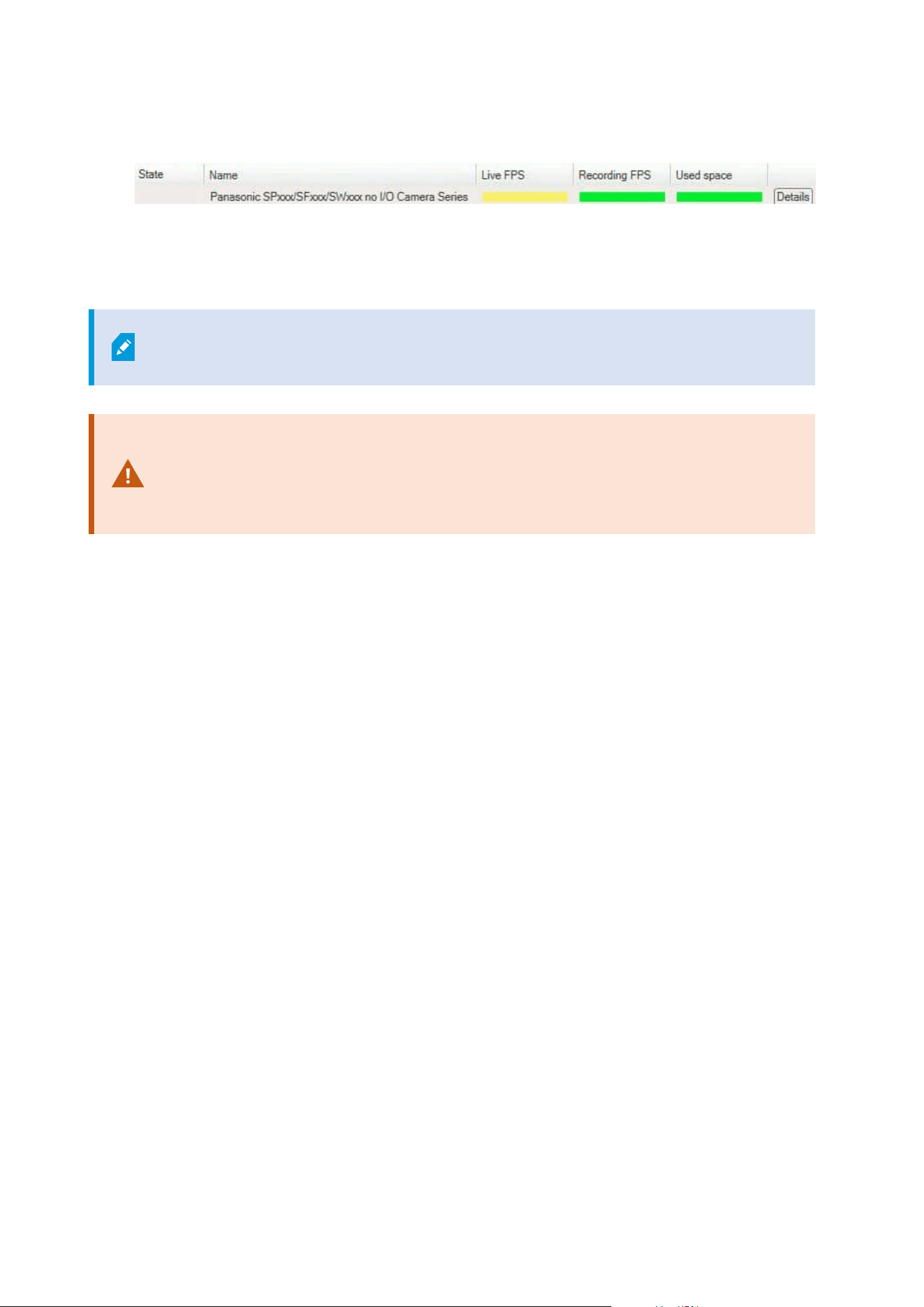
3. Select Details to the right side of the relevant server or camera.
4. For servers, select History to the right of the hardware that you want to investigate. For cameras, select
the link.
5. If you want to print a report, select the PDF icon.
You can only create historical reports with data from the recording server where the
device is currently located.
If you access the system monitor's details from a server operating system, you may
experience a message regarding Internet Explorer Enhanced Security Configuration.
Follow the instructions to add the System Monitor page to the Trusted sites zone
before proceeding.
Collect historical data of hardware states
You can enable the collection of historical data on the system's hardware to see graphs of the states of your
hardware over time and print a report. For more information, see View the historical state of your hardware
and print a report on page 279.
1. In the Site Navigation pane, select System Dashboard > System Monitor.
2. In the System Monitor window, select Customize.
3. In the Customize dashboard window that opens, select Collect historical data.
4. Select a sampling interval. The shorter the interval, the more load on the SQL Server database,
bandwidth, or other hardware. The sampling interval of historical data also determines how detailed
the graphs are.
Add a new camera or server tile on the System monitor dashboard
If you want to monitor your cameras or servers in smaller groups after their physical location, or if you want to
monitor some hardware with different monitoring parameters, you can add additional tiles to the System
Monitor window.
1. In the Site Navigation pane, select System Dashboard > System Monitor.
2. In the System Monitor window, select Customize.
3. In the Customize dashboard window that opens, select New under Server tiles or Camera tiles.
4. In the New server tile/New camera tile window, select the cameras or servers to monitor.
Administrator manual | XProtect® VMS 2023 R1
280 | Configuration

5. Under Monitoring parameters, select or clear check boxes for any parameters to add or remove from
the tile.
6. Select OK. The new server or camera tile is now added to the tiles displayed on your dashboard.
Edit a camera or server tile on the System monitor dashboard
If you want to monitor your cameras or servers with other monitoring parameters, you can adjust them.
1. In the Site Navigation pane, select System Dashboard > System Monitor.
2. In the System Monitor window, select Customize.
3. In the Customize dashboard window that opens, select the tile you want to change under Server tiles
or Camera tiles and select Edit.
4. In the Edit dashboard server/camera tile window, select all cameras or servers, a camera or server
group, or individual cameras or servers to change their monitoring parameters.
5. Under Monitoring parameters, select the monitoring parameters you want to monitor.
6. Select OK.
Delete a camera or server tile on the System monitor dashboard
If you no longer need to monitor the hardware represented by a tile, you can delete the tile.
1. In the Site Navigation pane, select System Dashboard > System Monitor.
2. In the System Monitor window, select Customize.
3. In the Customize dashboard window that opens, select the tile you want to change under Server tiles
or Camera tiles.
4. Select Delete.
Edit thresholds for when hardware states should change
You can edit the thresholds for when your hardware change between the three states on the System monitor
dashboard. For more information, see System monitor thresholds (explained) on page 278.
You can change thresholds for different types of hardware. For more information, see System Monitor
Thresholds (System Dashboard node) on page 541.
As a default, the system is set up to show threshold values for all units of the same hardware type, for
example, all cameras or servers. You can change these default threshold values.
You can also set up threshold values for individual servers or cameras or a subset of these to allow, for
example, that some cameras use a higher Live FPS or Recording FPS than other cameras.
Administrator manual | XProtect® VMS 2023 R1
281 | Configuration
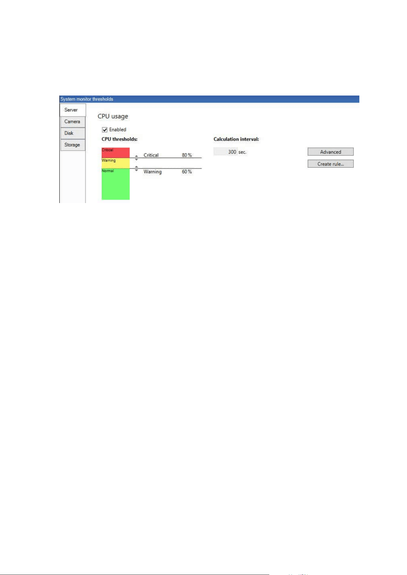
1. In the Site Navigation pane, select System Dashboard > System Monitor Thresholds.
2. Select the Enabled check box for the relevant hardware if you have not already enabled it. The figure
below shows an example.
3. Drag the threshold control slider up or down to increase or decrease the threshold value. There are two
sliders available for each hardware piece shown in the threshold control, separating the Normal,
Warning, and Critical states.
4. Enter a value for the calculation interval or keep the default value.
5. If you want to set values on individual pieces of hardware, select Advanced.
6. If you want to specify rules for certain events or within specific time intervals, select Create rule.
7. Once you have set the thresholds levels and calculation intervals, select File > Save from the menu.
View evidence locks in the system
Evidence Lock under the System Dashboard node shows an overview of all protected data on the current
surveillance system.
Find an evidence lock by filtering after, for example, who created it or when.
1. In the Site Navigation pane, select System Dashboard > Evidence Lock.
2. Get an overview and find the relevant evidence locks. You can filter after and sort the different
metadata related to the evidence locks.
All information shown in the Evidence Lock window is snapshots. Press F5 to refresh.
Print a report with your system configuration
You make many choices when you install and configure your VMS system, and you may need to document
these. Over time it is also hard to remember all the settings you have changed since the installation and initial
configuration - or just during the last couple of months. That is why it is possible to print a report with all your
configuration choices.
Administrator manual | XProtect® VMS 2023 R1
282 | Configuration

When you create a configuration report (PDF format), you can add any possible elements of your system to the
report. You can, for example, include licenses, device configuration, alarm configuration, and much more. You
can select the Exclude sensitive data option to create a GDPR compliant report (enabled by default). You can
also customize the font, the page setup, and the front page.
1. Expand System Dashboard and select Configuration Reports.
2. Select the elements that you want to include or exclude in your report.
3. Optional: If you have selected to include a frontpage, select Front Page to customize the information
on your front page. In the window that appears, fill in the needed info.
4. Select Formatting to customize your font, page size, and margins. In the window that appears, select
the wanted settings.
5. When you are ready to export, select Export and select a name and save location for your report.
Only users with administrator permissions in the VMS system can create configuration
reports.
Metadata
Show or hide metadata search categories and search filters
Users of XProtect Management Client with administrator permissions can show or hide the default Milestone
metadata search categories and search filters in XProtect Smart Client. By default, these search categories and
search filters are hidden. Showing them is useful if your video surveillance system meets the requirements (see
Metadata search requirements on page 548).
This setting affects all XProtect Smart Client users.
This setting does not affect the visibility of:
l
Other, non-metadata Milestone search categories and search filters, for example
Motion, Bookmarks, Alarms, and Events
l
Third-party search categories and search filters
1. In XProtect Management Client, in the Site Navigation pane, select Metadata Use >MetadataSearch.
2. In the MetadataSearch pane, select the search category that you want to change visibility settings for.
3. To enable the visibility of a search category or search filter, select the corresponding check box. To
disable the visibility of a search category or search filter, clear the check box.
Administrator manual | XProtect® VMS 2023 R1
283 | Configuration
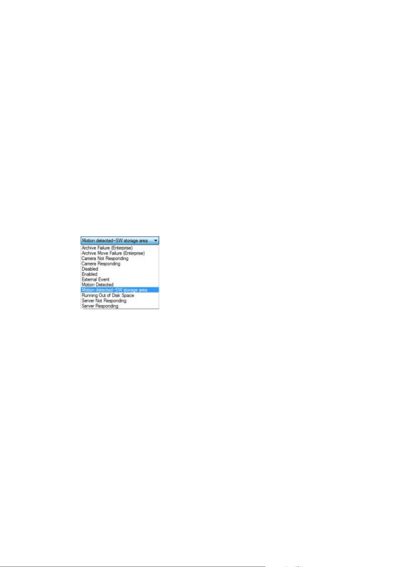
Alarms
Add an alarm
To define an alarm, you need to create an alarm definition, where you specify, for example, what triggers the
alarm, instructions on what the operator needs to do, and what or when the alarm stops. For detailed
information about the settings, see Alarm Definitions (Alarms node).
1. In the Site Navigation pane, expand Alarms, and right-click Alarm Definitions.
2. Select Add New.
3. Fill in these properties:
l
Name: Enter a name for the alarm definition. The name of the alarm definition appears
whenever the alarm definition is listed.
l
Instructions: You can write instructions for the operator who receives the alarm.
l
Triggering event: Use the drop-down menus to select an event type and an event message to
be used when the alarm is triggered.
A list of selectable triggering events. The one highlighted is created and customized using analytics
events.
l
Sources: Select the cameras or other devices that the event should originate from to trigger the
alarm. Your options depend on the type of event you have selected.
l
Time profile: If you want the alarm to be activated during a specific time interval, select the
radio button and then a time profile in the drop-down menu.
l
Event based: If you want the alarm definition to be activated by an event, select the radio button
and specify the event that will activate the alarm definition. You must also specify an event that
will deactivate the alarm definition.
4. In the Time limit drop-down menu, specify a time limit for when action is required by the operator.
5. In the Events triggered drop-down menu, specify which event to trigger when the time limit has
passed.
6. Specify additional settings, for example related cameras and initial alarm owner.
Administrator manual | XProtect® VMS 2023 R1
284 | Configuration
Enable encryption
Enable encryption to and from the management server
You can encrypt the two-way connection between the management server and the Data Collector affiliated
when you have a remote server of the following type:
l
Recording Server
l
Event Server
l
Log Server
l
LPR Server
l
Mobile Server
If your system contains multiple recording servers or remote servers, you must enable encryption on all of
them.
When you configure encryption for a server group, it must either be enabled with a
certificate belonging to the same CA certificate or, if the encryption is disabled, then it
must be disabled on all computers in the server group.
Prerequisites:
l
A server authentication certificate is trusted on the computer that hosts the management server
First, enable encryption on the management server.
Steps:
1. On a computer with a management server installed, open the Server Configurator from:
l
The Windows Start menu
or
l
The Management Server Manager by right-clicking the Management Server Manager icon on the
computer task bar
2. In the Server Configurator, under Server certificate, turn on Еncryption.
3. Click Select certificate to open a list with unique subject names of certificates that have a private key
and that are installed on the local computer in the Windows Certificate Store.
4. Select a certificate to encrypt communication between the recording server, management server,
failover server, and Data Collector server.
Administrator manual | XProtect® VMS 2023 R1
285 | Configuration
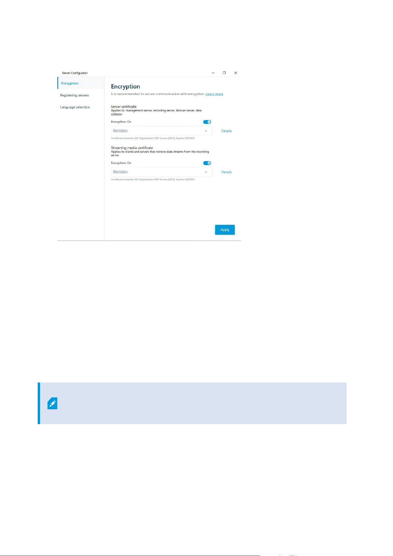
Select Details to view Windows Certificate Store information about the selected certificate.
5. Click Apply.
To complete the enabling of encryption, the next step is to update the encryption settings on each recording
server and each server that has a Data Collector (Event Server, Log Server, LPR Server, and Mobile Server).
For more information, see Enable server encryption for recording servers or remote servers on page 286.
Enable server encryption for recording servers or remote servers
You can encrypt the two-way connection between the management server and the recording server or other
remote servers that use the Data Collector.
If your system contains multiple recording servers or remote servers, you must enable encryption on all of
them.
For more information, see the certificates guide about how to secure your XProtect VMS installations.
When you configure encryption for a server group, it must either be enabled with a
certificate belonging to the same CA certificate or, if the encryption is disabled, then it
must be disabled on all computers in the server group.
Prerequisites:
l
You have enabled encryption on the management server, see Enable encryption to and from the
management server on page 285.
Administrator manual | XProtect® VMS 2023 R1
286 | Configuration
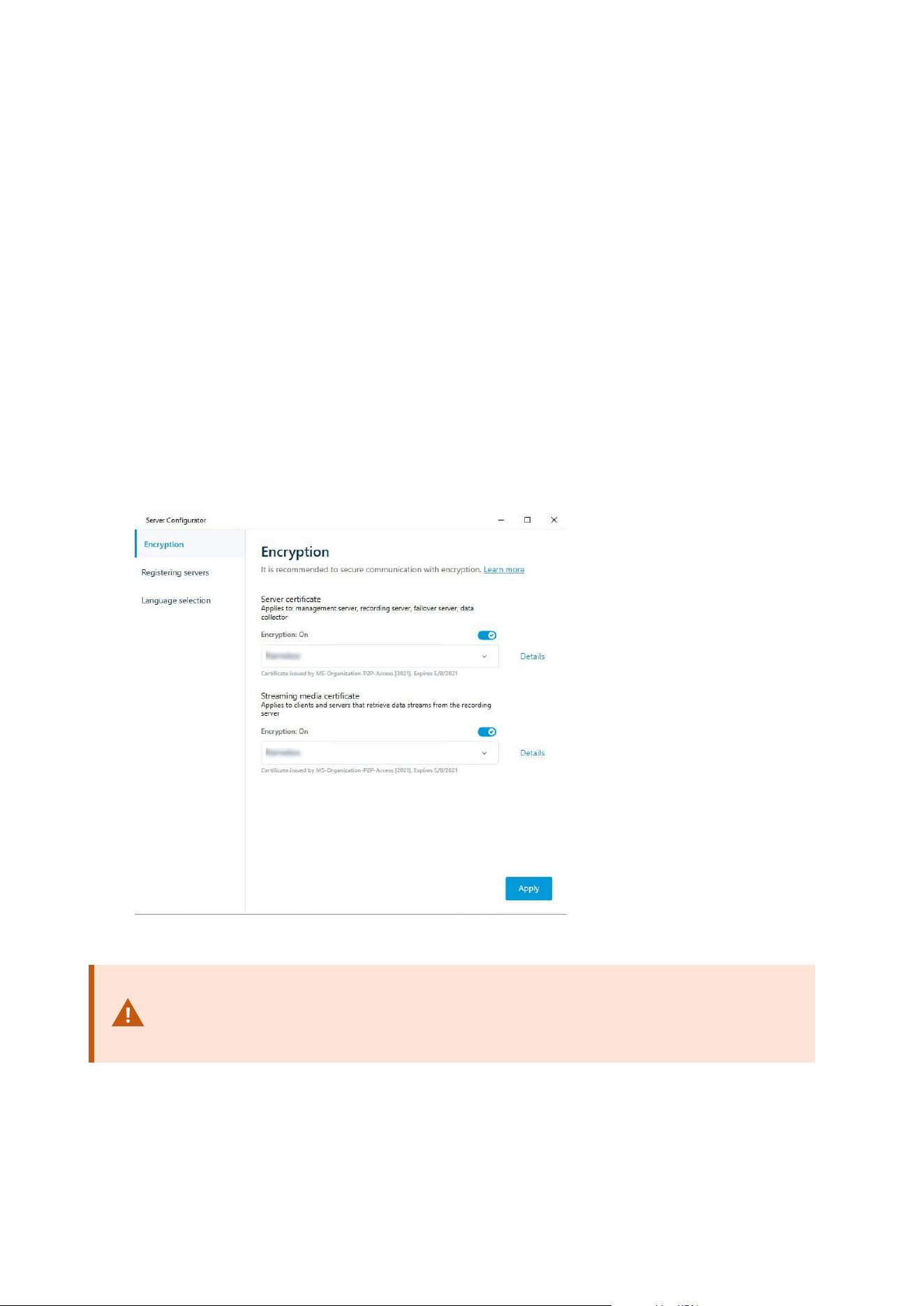
1. On a computer with a Management Server or Recording Server installed, open the Server Configurator
from:
l
The Windows Start menu
or
l
The server manager, by right-clicking the server manager icon on the computer task bar
2. In the Server Configurator, under Server certificate, turn on Еncryption.
3. Click Select certificate to open a list with unique subject names of certificates that have a private key
and that are installed on the local computer in the Windows Certificate Store.
4. Select a certificate to encrypt communication between the recording server, management server,
failover server, and data collector server.
Select Details to view Windows Certificate Store information about the selected certificate.
The Recording Server service user has been given access to the private key. It is required that this
certificate is trusted on all clients.
5. Click Apply.
When you apply certificates, the recording server will be stopped and restarted.
Stopping the Recording Server service means that you cannot record and view live video
while you are verifying or changing the recording server's basic configuration.
Administrator manual | XProtect® VMS 2023 R1
287 | Configuration

Enable event server encryption
You can encrypt the two-way connection between the event server and the components that communicate
with the event server, including the LPR Server.
When you configure encryption for a server group, it must either be enabled with a
certificate belonging to the same CA certificate or, if the encryption is disabled, then it
must be disabled on all computers in the server group.
Prerequisites:
l
A server authentication certificate is trusted on the computer that hosts the event server
First, enable encryption on the event server.
Steps:
1. On a computer with an event server installed, open the Server Configurator from:
l
The Windows Start menu
or
l
The Event Server by right-clicking the Event Server icon on the computer task bar
2. In the Server Configurator, under Event server and add-ons, turn on Encryption.
3. Click Select certificate to open a list with unique subject names of certificates that have a private key
and that are installed on the local computer in the Windows Certificate Store.
4. Select a certificate to encrypt communication between the event server and related add-ons.
Administrator manual | XProtect® VMS 2023 R1
288 | Configuration
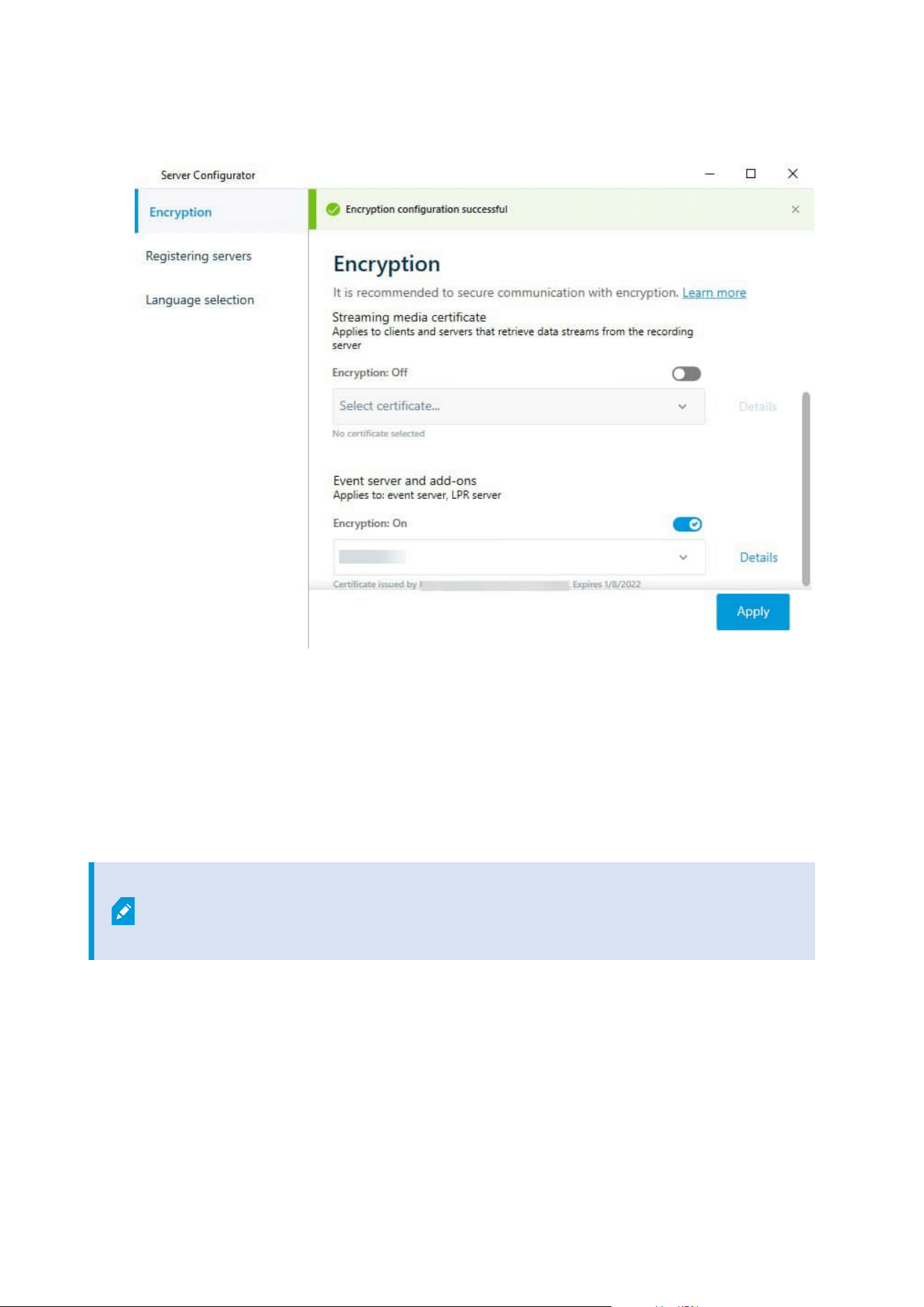
Select Details to view Windows Certificate Store information about the selected certificate.
5. Click Apply.
To complete the enabling of encryption, the next step is to update the encryption settings on each related add-
on LPR Server .
Enable encryption to clients and servers
You can encrypt connections from the recording server to clients and servers that stream data from the
recording server.
When you configure encryption for a server group, it must either be enabled with a
certificate belonging to the same CA certificate or, if the encryption is disabled, then it
must be disabled on all computers in the server group.
Prerequisites:
Administrator manual | XProtect® VMS 2023 R1
289 | Configuration

l
The server authentication certificate to be used is trusted on all computers running services that
retrieve data streams from the recording server
l
XProtect Smart Client and all services that retrieve data streams from the recording server must be
version 2019 R1 or later
l
Some third-party solutions created using MIP SDK versions earlier than 2019 R1 may need to be
updated
Steps:
1. On a computer with a recording server installed, open the Server Configurator from:
l
The Windows Start menu
or
l
The Recording Server Manager by right-clicking the Recording Server Manager icon on the
computer task bar
2. In the Server Configurator, under Streaming media certificate, turn on Еncryption.
3. Click Select certificate to open a list with unique subject names of certificates that have a private key
and that are installed on the local computer in the Windows Certificate Store.
4. Select a certificate to encrypt communication between the clients and servers that retrieve data streams
from the recording server.
Select Details to view Windows Certificate Store information about the selected certificate.
The Recording Server service user has been given access to the private key. It is required that this
Administrator manual | XProtect® VMS 2023 R1
290 | Configuration
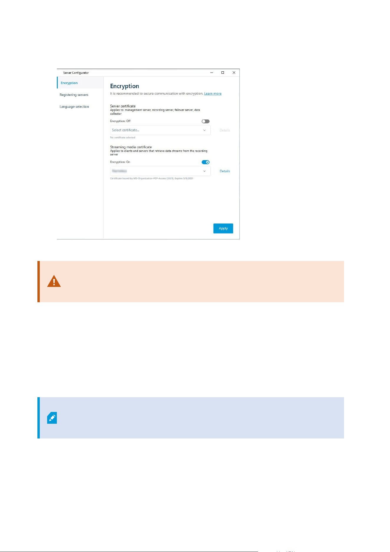
certificate is trusted on all clients.
5. Click Apply.
When you apply certificates, the recording server will be stopped and restarted.
Stopping the Recording Server service means that you cannot record and view live video
while you are verifying or changing the recording server's basic configuration.
To verify if the recording server uses encryption, see View encryption status to clients.
Enable encryption on the mobile server
To use an HTTPS protocol for establishing a secure connection between the mobile server and clients and
services, you must apply a valid certificate on the server. The certificate confirms that the certificate holder is
authorized to establish secure connections.
For more information, see the certificates guide about how to secure your XProtect VMS installations.
When you configure encryption for a server group, it must either be enabled with a
certificate belonging to the same CA certificate or, if the encryption is disabled, then it
must be disabled on all computers in the server group.
Administrator manual | XProtect® VMS 2023 R1
291 | Configuration

Certificates issued by CA (Certificate Authority) have a chain of certificates and on the
root of that chain is the CA root certificate. When a device or browser sees this
certificate, it compares its root certificate with pre-installed ones on the OS (Android,
iOS, Windows, etc.). If the root certificate is listed in the pre-installed certificates list, then
the OS ensures the user that the connection to the server is secure enough. These
certificates are issued for a domain name and are not free of charge.
Steps:
1. On a computer with a mobile server installed, open the Server Configurator from:
l
The Windows Start menu
or
l
The Mobile Server Manager by right-clicking the Mobile Server Manager icon on the computer
task bar
2. In the Server Configurator, under Mobile streaming media certificate, turn on Еncryption.
3. Click Select certificate to open a list with unique subject names of certificates that have a private key
and that are installed on the local computer in the Windows Certificate Store.
4. Select a certificate to encrypt the communication of XProtect Mobile client and XProtect Web Client with
the mobile server.
Select Details to view Windows Certificate Store information about the selected certificate.
The Mobile Server service user has been given access to the private key. It is required that this
Administrator manual | XProtect® VMS 2023 R1
292 | Configuration
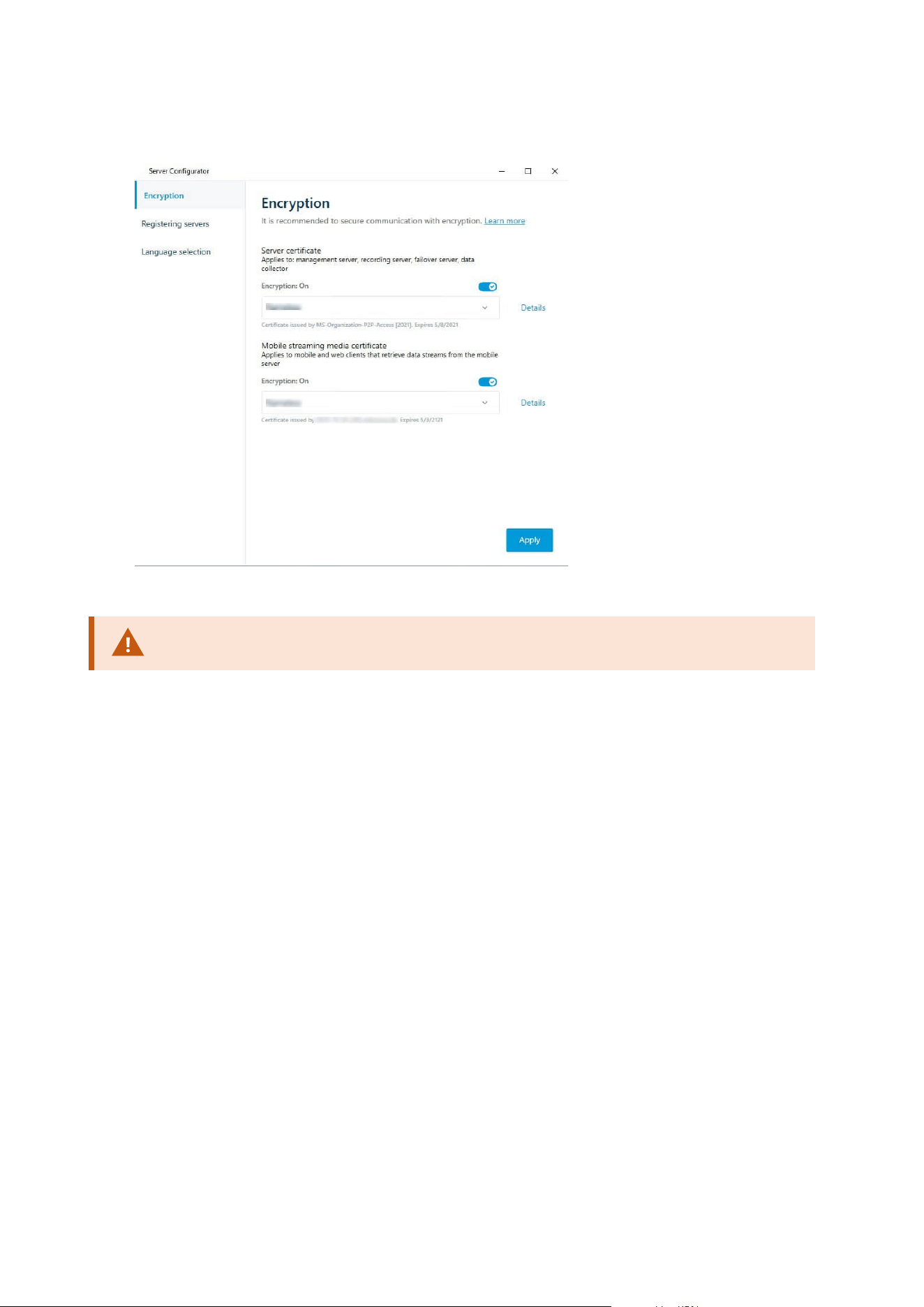
certificate be trusted on all clients.
5. Click Apply.
When you apply certificates, the Mobile Server service restarts.
Milestone Federated Architecture
Set up your system to run federated sites
To prepare your system for Milestone Federated Architecture, you must make certain choices when you install
the management server. Depending on how your IT infrastructure is set up, choose between three different
alternatives.
Alternative 1: Connect sites from the same domain (with a common domain user)
Before you install the management server, you must create a common domain user and configure this user as
the administrator on all servers involved in the federated site hierarchy. How you connect the sites depends on
the created user account.
Administrator manual | XProtect® VMS 2023 R1
293 | Configuration

With a Windows user account
1. Start the installation of the product on the server to be used as the management server and select
Custom.
2. Select to install the Management Server service using a user account. The selected user account must
be the administrator account used on all management servers. You must use the same user account
when you install the other management servers in the federated site hierarchy.
3. Finish the installation. Repeat steps 1-3 to install any other systems you want to add to the federated
site hierarchy.
4. Add site to hierarchy (see Add site to hierarchy on page 295).
With a Windows built-in user account (network service)
1. Start the installation of the product on the first server to be used as the management server and select
Single Computer or Custom. This installs the management server using a network service account.
Repeat this step for all the sites in your federated site hierarchy.
2. Log into the site that you want as your central site in the federated site hierarchy.
3. In the Management Client, expand Security > Roles > Administrators.
4. On the Users and Groups tab, click Add and select Windows User.
5. In the dialog box, select Computers as object type, enter the server name of the federated site and click
OK to add the server to the Administrator role of the central site. Repeat this step until you have added
all the federated sites in this way and exit the application.
6. Log into each federated site, and add the following servers to the Administrator role, in the same way
as above:
l
The parent site server.
l
The child site servers that you want to connect directly to this federated site.
7. Add site to hierarchy (see Add site to hierarchy on page 295).
Alternative 2: Connecting sites from different domains
To connect to sites across domains, make sure that the domains trust each other. You set up domains to trust
each other in the Microsoft Windows Domain configuration. When you have established trust between the
different domains on each site in the federated site hierarchy are placed, follow the same description as
described in Alternative 1. For more information about how to set up trusted domains, see the Microsoft
website (https://docs.microsoft.com/previous-versions/windows/it-pro/windows-2000-server/cc961481
(v=technet.10)/).
Administrator manual | XProtect® VMS 2023 R1
294 | Configuration
Milestone recommends Milestone Interconnect for creating connected multi-site
systems with multiple domains.
Alternative 3: Connect sites in workgroup(s)
When you connect sites inside workgroups, the same administrator account must be present on all servers you
want connected in the federated site hierarchy. You must define the administrator account before you install
the system.
1. Log into Windows using a common administrator account.
2. Start the installation of the product and click Custom.
3. Select to install the Management Server service using the common administrator account.
4. Finish the installation. Repeat steps 1-4 to install any other systems you want to connect. You must
install all of these systems using the common administrator account.
5. Add site to hierarchy (see Add site to hierarchy on page 295).
Milestone recommends Milestone Interconnect for creating connected multi-site
systems when the sites are not part of a domain.
You cannot mix domain(s) and workgroup(s). This means that you cannot connect sites
from a domain to sites from a workgroup and vice versa.
Add site to hierarchy
As you expand your system, you can add sites to your top site and to its child sites as long as the system is set
up correctly.
When adding a non-secure site to Milestone Federated Architecture, make sure that Allow non-secure
connections to the server is enabled under Tools > Options > General settings in Management Client.
1. Select the Federated Site Hierarchy pane.
2. Select the site to which you want to add a child site, right-click, and click Add Site to Hierarchy.
3. Enter the URL of the requested site in the Add Site to Hierarchy window and click OK.
4. The parent site sends a link request to the child site and after a while, a link between the two sites is
added to the Federated Site Hierarchy pane.
Administrator manual | XProtect® VMS 2023 R1
295 | Configuration

5. If you can establish the link to the child site without requesting acceptance from the child site
administrator, go to step 7.
If not, the child site has the awaiting acceptance
icon until the administrator of the child site has
authorized the request.
6. Make sure that the administrator of the child site authorizes the link request from the parent site (see
Accept inclusion in the hierarchy on page 296).
7.
The new parent/child link is established and the Federated Site Hierarchy pane is updated with the
icon for the new child site.
Accept inclusion in the hierarchy
When a child site has received a link request from a potential parent site where the administrator did not have
administrator permissions to the child site, it has the awaiting acceptance
icon.
To accept a link request:
1. Log into the site.
2. In the Federated Site Hierarchy pane, right-click the site and click Accept Inclusion in Hierarchy.
If the site runs the XProtect Expert version, you right-click the site in the Site Navigation pane.
3. Click Yes.
4. The new parent/child link is established and the Federated Site Hierarchy pane is updated with the
normal site
icon for the selected site.
Changes that you make to child sites located far from the parent site can take some time
to be reflected in the Federated Site Hierarchy pane.
Set site properties
You can view and, possibly, edit properties on your home site and its child sites.
Administrator manual | XProtect® VMS 2023 R1
296 | Configuration
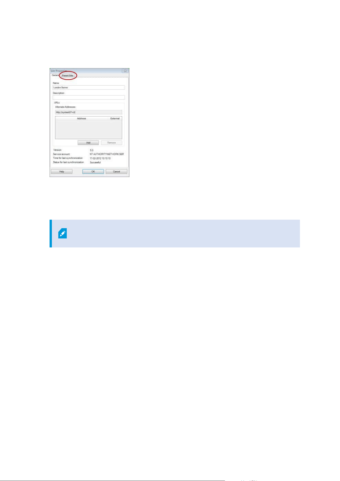
1. In the Management Client, in the Federated Site Hierarchy pane, select the relevant site, right-click,
and select Properties.
2. If needed, change the following:
General tab (see General tab on page 564)
Parent Site tab (see Parent Site tab on page 564) (available on child sites only)
Due to synchronization issues, any changes made to remote children might take
some time to be reflected in the Site Navigation pane.
Refresh site hierarchy
Regularly the system automatically synchronizes the hierarchy through all levels of your parent/child setup.
You can refresh it manually, if you want to see changes reflected instantly in the hierarchy, and do not want to
wait for the next automatic synchronization.
You need to be logged into a site to perform a manual refresh. Only changes saved by this site since the last
synchronization are reflected by a refresh. This means that changes made further down in the hierarchy might
not be reflected by the manual update, if the changes have not reached the site yet.
1. Log into the relevant site.
2. Right-click the top site in the Federated Site Hierarchy pane and click Refresh Site Hierarchy.
This will take a few seconds.
Log into other sites in the hierarchy
You can log into other sites and administrate these. The site you are logged into is your home site.
Administrator manual | XProtect® VMS 2023 R1
297 | Configuration

1. In the Federated Site Hierarchy pane, right-click the site that you want to log into.
2. Click Log into Site.
The Management Client for that site opens.
3. Enter login information and click OK.
4. After login is complete, you are ready to do your administrative tasks for that site.
Update site information of child sites
This section is only relevant if you use XProtect Corporateor XProtect Expert2014 or
newer.
In a large Milestone Federated Architecture setup with a lot of child sites, it is easy to lose the overview and it
can be difficult to find the contact information to the administrators of each child site.
Therefore, you can add additional information to each child site and this information is then available for the
administrators on the central site.
You can read the information about the site, when you pause your mouse over the site name in the Federated
Site Hierarchy pane. To update information about the site:
1. Log into the site.
2. Click Site Navigation pane and select Site Information.
3. Click Edit and add the relevant information in each category.
Detach a site from the hierarchy
When you detach a site from its parent site, the link between the sites are broken. You can detach sites from
the central site, from the site itself or its parent site.
1. In the Federated Site Hierarchy pane, right-click the site, and click Detach Site from Hierarchy.
2. Click Yes to update the Federated Site Hierarchy pane.
If the detached site has child sites, it becomes the new top site for this branch of the hierarchy, and the
normal site icon
changes to a top site icon.
3. Click OK.
The changes to the hierarchy are reflected after a manual refresh or an automatic synchronization.
Administrator manual | XProtect® VMS 2023 R1
298 | Configuration

Milestone Interconnect
Add a remote site to your central Milestone Interconnect site
You add remote sites to the central site with the Add Hardware wizard.
Requirements
l
Enough Milestone Interconnect camera licenses (see Milestone Interconnect and licensing on page 86).
l
Another configured and working XProtect system including a user account (basic users, local Windows
user or Windows Active Directory user) with permissions for the devices that the central XProtect
Corporate system should be able to access
l
Network connection between the central XProtect Corporate site and the remote sites with access or
port forwarding to the ports used on the remote sites
To add a remote site:
1. On the central site, expand Servers and select Recording Servers.
2. In the Overview pane, expand the relevant recording server and right-click.
3. Select Add Hardware to start the wizard.
4. On the first page select Address range scanning or Manual and click Next.
5. Specify user names and passwords. The user account must be predefined on the remote system. You
can add user names and passwords as needed by clicking Add. When ready, click Next.
6. Select the drivers to use when you scan. In this case choose between the Milestone drivers. Click Next.
7. Specify the IP addresses and port numbers you want to scan. Default is port 80. Click Next.
Wait while your system detects the remote sites. A status indicator shows the detection process. In case
of a successful detection, a Success message appears in the Status column. If you fail to add, you can
click the Failed error message to see why.
8. Choose to enable or disable successfully detected systems. Click Next.
9. Wait while your system detects hardware and collects device specific information. Click Next.
10. Choose to enable or disable successfully detected hardware and devices. Click Next.
11. Select a default group. Click Finish.
12. After installation, you can see the system and its devices in the Overview pane.
Depending on the user permissions for the selected user on the remote site, the central site gets access
to all cameras and functions or a sub-set of them.
Assign user permissions
You configure user permissions for an interconnected camera as you do with other cameras, by creating a role
and assigning access to functions.
Administrator manual | XProtect® VMS 2023 R1
299 | Configuration

1. On the central site, in the Site Navigation pane, expand Security and select Roles.
2. In the Overview pane, right-click the built-in administrator role and select Add Role (see Add and
manage a role).
3. Name the role and configure the settings on the Device tab (see Device tab (roles)) and the Remote
Recordings tab (see Remote recordings tab (roles)).
Update remote site hardware
If the configuration has been changed on a remote site, for example, added or removed cameras and events,
you must update the configuration on the central site to reflect the new configuration on the remote site.
1. On the central site, expand Servers and select Recording Servers.
2. In the Overview pane, expand the required recording server, select the relevant remote system. Right-
click it.
3. Select Update Hardware. This opens the Update hardware dialog box.
4. The dialog box lists all changes (devices removed, updated and added) in the remote system since your
Milestone Interconnect setup was established or refreshed last. Click Confirm to update your central
site with these changes.
Enable playback directly from remote site camera
If your central site is continuously connected with its remote sites, you can configure your system so that the
users playback the recordings directly from the remote sites. For more information, see Milestone
Interconnect setups (explained) on page 86.
1. On the central site, expand Servers and select Recording Servers.
2. In the Overview pane, expand the required recording server, select the relevant remote system. Select
the relevant interconnected camera.
3. In the Properties pane, select the Record tab, and select the Play back recordings from remote
system option.
4. In the toolbar, click Save.
In a Milestone Interconnect setup, the central site disregards privacy masks defined in a remote site. If you
want to apply the same privacy masks, you must redefine it on the central site.
Retrieve remote recordings from remote site camera
If your central site is not continuously connected with its remote sites, you can configure your system to store
remote recordings centrally and you can configure retrieval of remote recordings when the network
connection is optimal. For more information, see Milestone Interconnect setups (explained) on page 86.
To allow users to actually retrieve recordings, you must enable this permission for the relevant role (see Roles
(Security)).
Administrator manual | XProtect® VMS 2023 R1
300 | Configuration

To configure your system:
1. On the central site, expand Servers and select Recording Servers.
2. In the Overview pane, expand the required recording server, select the relevant remote system. Select
the relevant remote server.
3. In the Properties pane, select the Remote Retrieval tab and update the settings (see Remote Retrieval
tab on page 412).
If the network fails for some reason, the central site misses out on recording sequences. You can configure
your system to let the central site automatically retrieve remote recordings to cover the down-period, once the
network is reestablished.
1. On the central site, expand Servers and select Recording Servers.
2. In the Overview pane, expand the required recording server, select the relevant remote system. Select
the relevant camera.
3. In the Properties pane, select the Record tab, and select the Automatically retrieve remote recordings
when connection is restored option (see Save and retrieve remote recording).
4. In the toolbar, click Save.
As an alternative, you can use rules or start remote recording retrievals from XProtect Smart Client when
needed.
In a Milestone Interconnect setup, the central site disregards privacy masks defined in a remote site. If you
want to apply the same privacy masks, you must redefine it on the central site.
Configure your central site to respond to events from remote sites
You can use events defined on the remote sites to trigger rules and alarms on your central site and thereby
respond immediately to events from the remote sites. This requires that the remote sites are connected and
online. The number and type of events depend on the events configured and predefined in the remote sites.
The list of supported events is available on the Milestone website (https://www.milestonesys.com/).
You cannot delete predefined events.
Requirements:
l
If you want to use user-defined/manual events from the remote sites as triggering events, you must
first create these on the remote sites
l
Make sure that you have an updated list of events from the remote sites (see Update remote site
hardware on page 300).
Administrator manual | XProtect® VMS 2023 R1
301 | Configuration

Add a user-defined/manual event from a remote site:
1. On the central site, expand Servers and select Recording Servers.
2. In the Overview pane, select the relevant remote server and the Events tab.
3. The list contains the predefined events. Click Add to include user-defined or manual events from the
remote site in the list.
Use an event on a remote site to trigger an alarm on the central site:
1. On the central site, expand Alarms and select Alarm Definitions.
2. In the Overview pane, right-click Alarm Definitions and click Add New.
3. Enter values as needed.
4. In the Triggering Event field, you can select between the supported predefined and user-defined
events.
5. In the Sources field, select the remote server representing the remote site that you want alarms from.
6. Save the configuration when done.
Use an event on a remote site to trigger a rule-based action on the central site:
1. On the central site, expand Rules and Events and select Rules.
2. In the Overview pane, right-click Rules and click Add Rule.
3. In the wizard that appears, select Perform an action on <event>.
4. In the Edit the rule description area, click event and select between the supported predefined and
user-defined events. Click OK.
5. Click devices/recording server/management server and select the remote server representing the
remote site that you want the central site to start an action for. Click OK.
6. Click Next to get to the next wizard page.
7. Select the conditions that you want to apply for this rule. If you do not select any conditions, the rule
always applies. Click Next.
8. Select an action and specify the details in the Edit the rule description area. Click Next.
9. Select a stop criterion if required. Click Next.
10. Select a stop action if required. Click Finish.
Administrator manual | XProtect® VMS 2023 R1
302 | Configuration

Remote connect services
Remote connect services (explained)
Available functionality depends on the system you are using. See the complete feature
list, which is available on the product overview page on the Milestone website
(https://www.milestonesys.com/solutions/platform/product-index/).
The remote connect services feature contains the Axis One-click Camera Connection technology developed by
Axis Communications. It enables the system to retrieve video (and audio) from external cameras where
firewalls and/or router network configuration normally prevents initiating connections to such cameras. The
actual communication takes place via secure tunnel servers (ST servers). ST servers use VPN. Only devices that
hold a valid key work within a VPN. This offers a secure tunnel where public networks can exchange data in a
safe way.
Remote connect services allows you to
l
Edit credentials within the Axis Dispatch Service
l
Add, edit, and remove ST servers
l
Register/unregister and edit Axis One-click cameras
l
Go to the hardware related to the Axis One-Click camera
Install secure tunnel server environment for One-Click camera connection
Before you can use Axis One-click Camera Connection, you must first install a suitable ST server environment.
To work with secure tunnel server (ST server) environments and Axis One-click cameras, you must first contact
your system provider to obtain the needed user name and password for Axis Dispatch Services.
Requirements
l
Contact your system provider to obtain the needed user name and password for Axis Dispatch Services
l
Make sure your camera(s) support Axis Video Hosting System. Go to the Axis website to see supported
devices (https://www.axis.com/products/axis-guardian)
l
If needed, update your Axis cameras with the newest firmware. Go to the Axis website to download
firmware (https://www.axis.com/support/firmware)
1. On each camera's homepage, go to Basic Setup, TCP/IP, and select Enable AVHS and Always.
2. From your management server, go to the Milestone download page
(https://www.milestonesys.com/downloads/) and download the AXIS One-Click software. Run the
program to setup a suitable Axis secure tunnel framework.
Add or edit secure tunnel servers
Communication for remote connect services takes place via secure tunnel servers (ST servers).
Administrator manual | XProtect® VMS 2023 R1
303 | Configuration
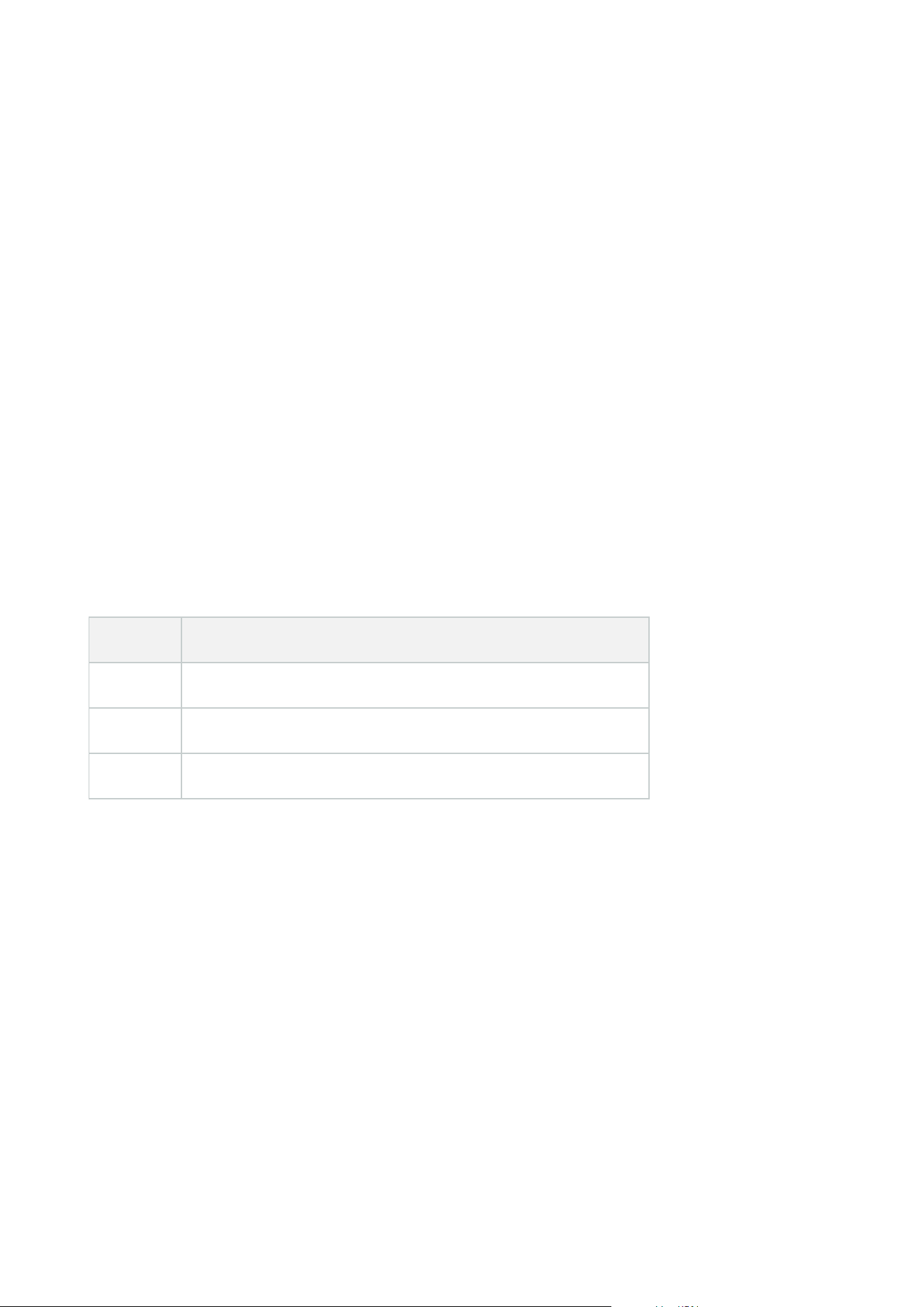
1. Do one of the following:
l
To add an ST server, right-click the Axis Secure Tunnel Servers top node, select Add Axis Secure
Tunnel Server
l
To edit an ST server, right-click it, select Edit Axis Secure Tunnel Server
2. In the window that opens, fill in the relevant information.
3. If you chose to use credentials when you installed the Axis One-Click Connection Component, select
the Use credentials check box and fill in the same user name and password as used for the Axis One-
Click Connection Component.
4. Click OK.
Register new Axis One-Click camera
1. To register a camera under an ST server, right-click it and select Register Axis One-Click Camera.
2. In the window that opens, fill in the relevant information.
3. Click OK.
4. The camera now appears under the relevant ST server.
The camera can have the following color coding:
Color Description
Red Initial state. Registered, but not connected to the ST server.
Yellow Registered. Connected to the ST server, but not added as hardware.
Green Added as hardware. May or may not be connected to the ST server.
When you add a new camera, its status is always green. The connection status is reflected by Devices on
Recording Servers in the Overview pane. In the Overview pane, you may group your cameras for an easier
overview. If you choose not to register your camera at the Axis dispatch service at this point, you can do so
later from the right-click menu (select Edit Axis One-Click Camera).
Smart maps
Geographic backgrounds (explained)
Before a user of XProtect Smart Client can select a geographic background, first you must configure the
geographic backgrounds in XProtect Management Client.
Administrator manual | XProtect® VMS 2023 R1
304 | Configuration
l
Basic world map - use the standard geographic background provided in XProtect Smart Client. It
requires no configuration. This map is intended for use as a general reference, and it does not contain
features such as country boundaries, cities, or other details. However, like the other geographic
backgrounds, it does contain geo-reference data
l
Bing Maps - connect to Bing Maps
l
Google Maps - connect to Google Maps
l
Milestone Map Service - connect to a free map provider. After you enable Milestone Map Service, no
further setup is needed.
See Enable Milestone Map Service
l
OpenStreetMap - connect to:
l
A commercial tile server of your own choice
l
Your own, online or local tile server
See Specify OpenStreetMap tile server
The Bing Maps and Google Maps options require access to the internet, and you must
purchase a key from Microsoft or Google.
Milestone Map Service requires internet access.
Unless you are using your own, local tile server, OpenStreetMap requires internet
access.
If you want the system to have a EU GDPR compliant installation, the following services
may not be used:
l
Bing Maps
l
Google Maps
l
Milestone Map Service
For more information about data protection and the usage data collection, see the
GDPRprivacy guide.
By default, Bing Maps and Google Maps display satellite imagery (Satellite). You can change the imagery in
XProtect Smart Client, for example to aerial or terrain, to see different details.
Administrator manual | XProtect® VMS 2023 R1
305 | Configuration
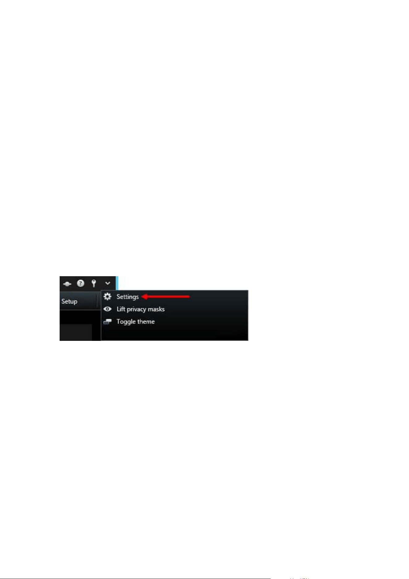
Enable Bing Maps or Google Maps in Management Client
You can make a key available to multiple users by entering it for a Smart Client profile in Management Client.
All users who are assigned to the profile will use this key.
Steps:
1. In Management Client, on the Site Navigation pane, click Smart Client Profiles.
2. In the Smart Client Profiles pane, select the relevant Smart Client profile.
3. In the Properties pane, click the Smart map tab:
l
For Bing Maps, enter your Basic Key or Enterprise Key in the Bing Maps key field
l
For Google Maps, enter your Maps Static APIkey in the Private key for Google Maps field
4. To prevent XProtect Smart Client operators from using a different key, select the Locked check box.
Enable Bing Maps or Google Maps in XProtect Smart Client
To allow XProtect Smart Client operators to use a different key than the key from the Smart Client profile, you
must enter the key in the settings in XProtect Smart Client.
Steps:
1. In XProtect Smart Client, open the Settings window.
2. Click Smart map.
3. Depending on the map service you want to use, do one of the following:
l
For Bing Maps, enter your key in the Bing Maps key field
l
For Google Maps, enter your key in the Private key for Google Maps field
Enable Milestone Map Service
Milestone Map Service is an online service that lets you connect to Milestone Systems's tile server. This tile
server uses a free, commercially available map service.
After you enable Milestone Map Service on your smart map, the smart map will use Milestone Map Service as
its geographic background.
Steps:
Administrator manual | XProtect® VMS 2023 R1
306 | Configuration
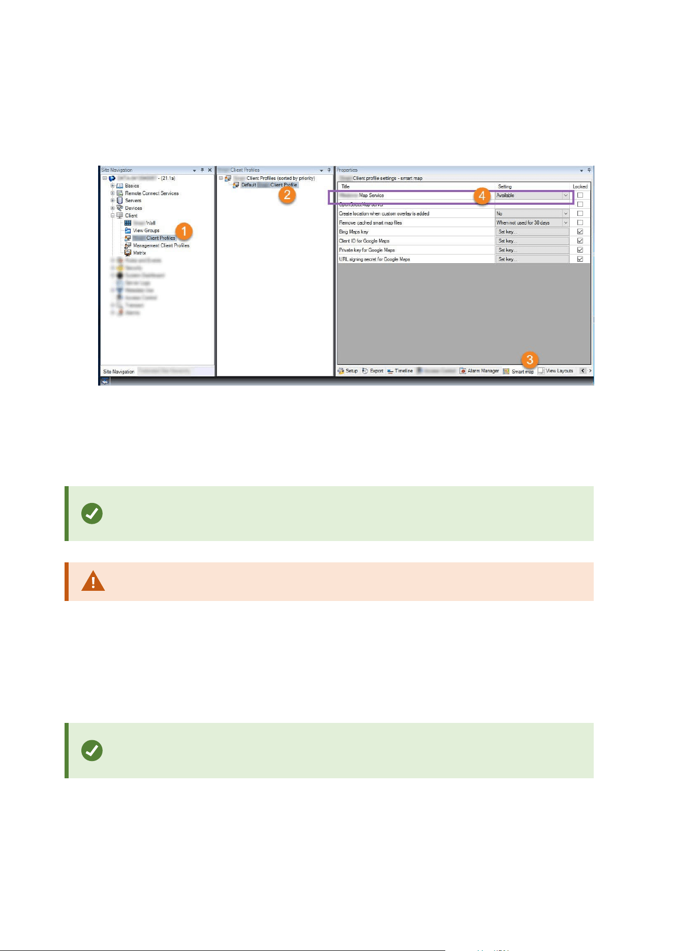
1. In the Site Navigation pane, expand the Client node and click Smart Client Profiles.
2. In the overview pane, select the relevant Smart Client profile.
3. In the Properties pane, click the Smart map tab.
4. In the Milestone Map Service field, select Available.
5. To enforce this setting in XProtect Smart Client, select the Locked check box. Then the XProtect Smart
Client operators cannot enable or disable Milestone Map Service.
6. Save the changes.
You can also enable Milestone Map Service in the Settings window in XProtect Smart
Client.
Milestone Map Service requires internet access.
Specify OpenStreetMap tile server
If you use the OpenStreetMap option as the geographic background for your smart map, you must specify
where the tiled images are retrieved from. You do this by specifying the tile server address, either a
commercial tile server or a local tile server, for example if your organization has its own maps for areas such as
airports or harbors.
You can also specify the tile server address in the Settings window in XProtect Smart
Client.
Steps:
Administrator manual | XProtect® VMS 2023 R1
307 | Configuration
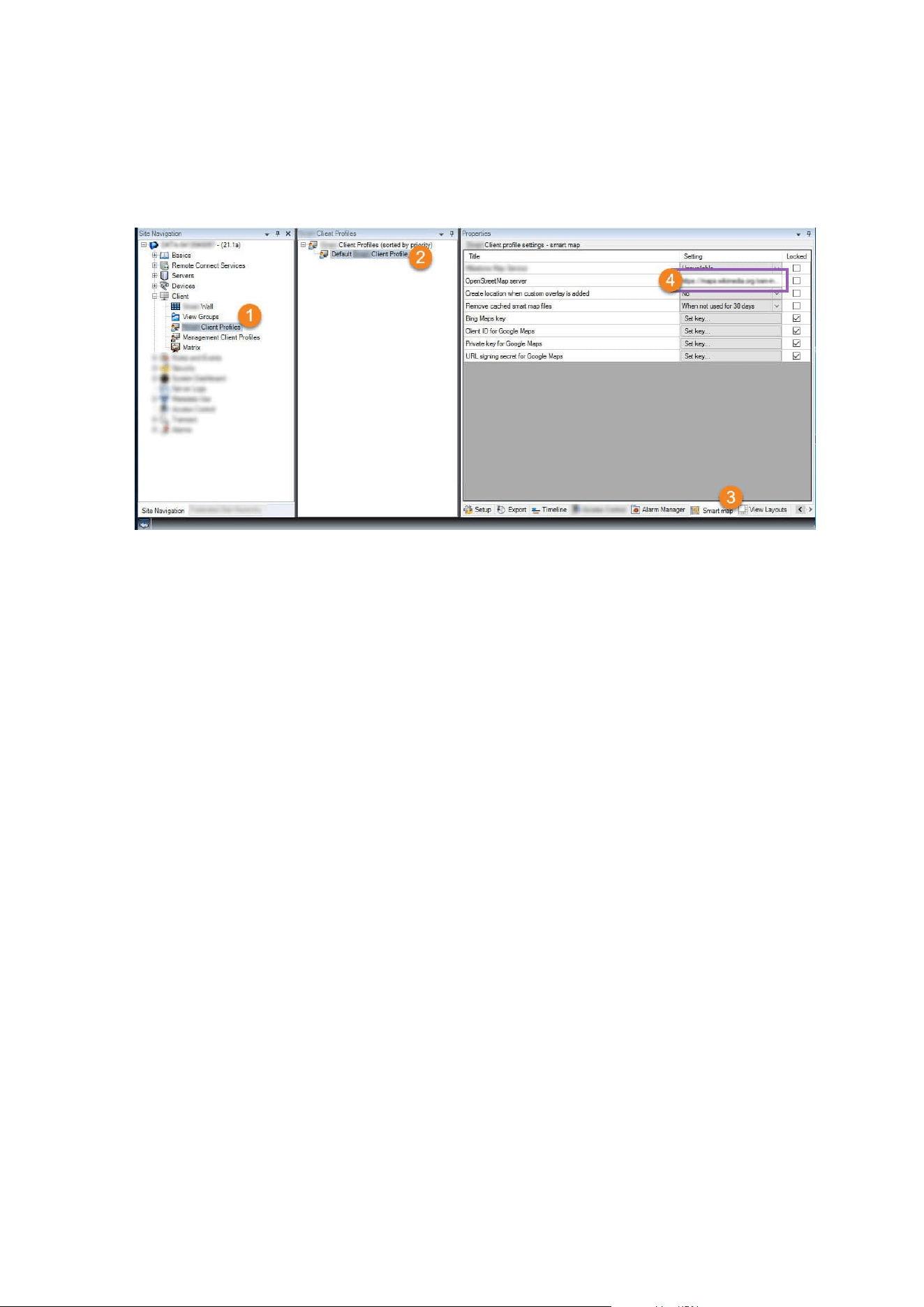
1. In the Site Navigation pane, expand the Client node and click Smart Client Profiles.
2. In the overview pane, select the relevant Smart Client profile.
3. In the Properties pane, click the Smart map tab.
4. In the OpenStreetMap server field, enter the address of the tile server.
5. To enforce this setting in XProtect Smart Client, select the Locked check box. Then the XProtect Smart
Client operators cannot change the address.
6. Save the changes.
Enable smart map editing
Operators can edit smart maps in XProtect Smart Client in setup mode only if editing is enabled in
Management Client. If not already enabled, you need to enable editing for each relevant Smart Client profile.
Steps:
Administrator manual | XProtect® VMS 2023 R1
308 | Configuration
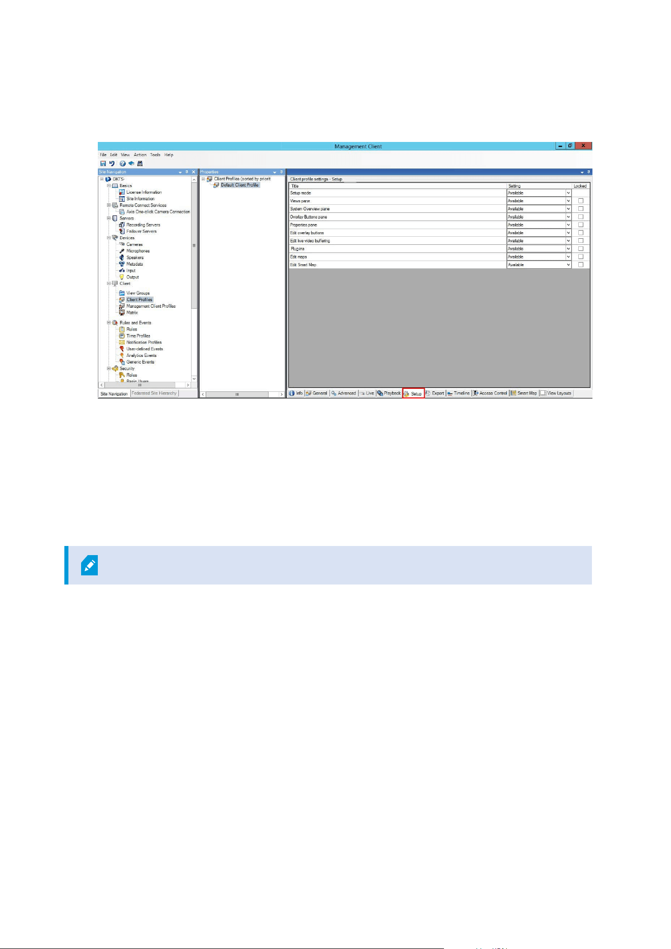
1. In the Site Navigation pane, expand the Client node.
2. Click Smart Client Profiles.
3. In the overview pane, select the relevant Smart Client profile.
4. In the Properties pane, click the Setup tab.
5. In the Edit smart map list, select Available.
6. Repeat these steps for each relevant Smart Client profile.
7. Save your changes. Next time users assigned to the Smart Client profile you selected log into XProtect
Smart Client, they will be able to edit smart maps.
To disable editing, in Edit smart map list, select Unavailable.
Enable editing devices on smart map
You must enable the editing of devices per role to allow operators to, for example:
l
Position an input device or a microphone on a smart map
l
Adjust the field of view of a camera on a smart map
Operators can be allowed to edit the following device types on smart maps:
l
Cameras
l
Input devices
l
Microphones
Administrator manual | XProtect® VMS 2023 R1
309 | Configuration

Requirements
Before you start, make sure that smart map editing has been enabled (see Enable smart map editing on page
308). You do this on the Smart Client profile that the role of the operator is associated with.
Steps:
1. Expand the Security node > Roles.
2. In the Roles pane, select the role that your operator is associated with.
3. To give the role editing permissions:
l
Select the Overall Security tab, and in the Role Settings pane, select the device type (for
example, Cameras or Input)
l
In the Allow column, select the Full control or Edit check box
4. Save the changes.
To enable the editing of individual devices, go to the Device tab and select the relevant
device.
Define device position and camera direction, field of view, depth (smart map)
To ensure that a device is positioned correctly on the smart map, you can set the geographic coordinates of
the device. For cameras, you can also set the direction, the field of view, and the viewing depth. Setting any of
the above will automatically add the device to the smart map the next time an operator loads the smart map in
XProtect Smart Client.
Steps:
1. In Management Client, expand the Devices node and select the device type (for example, Cameras or
Input).
2. In the Devices pane, select the relevant device.
Administrator manual | XProtect® VMS 2023 R1
310 | Configuration
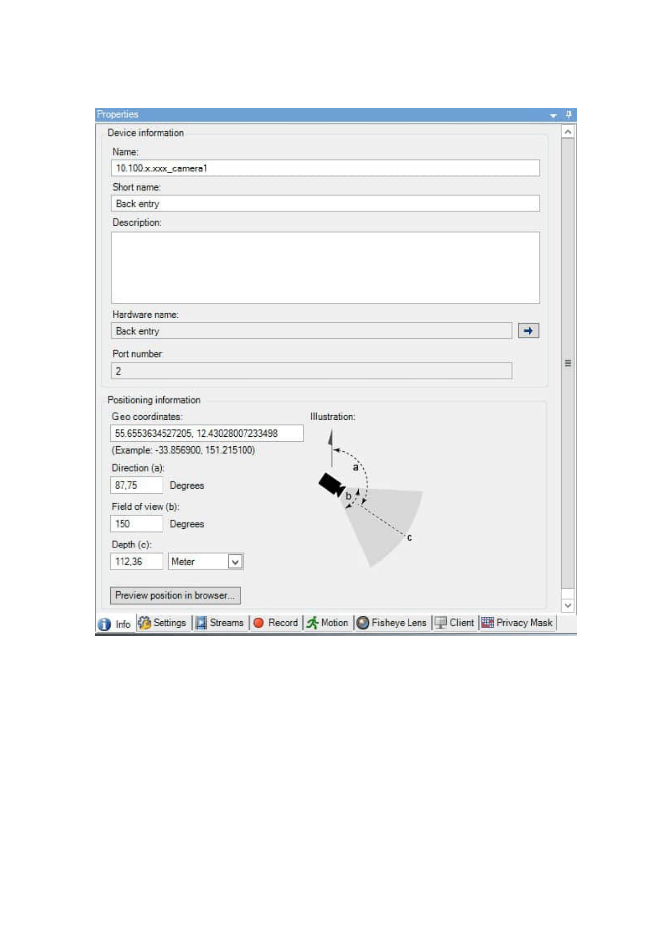
3. OntheInfotab,scrolldowntoPositioninginformation.
4. In the Geo coordinates field, specify the latitude and the longitude coordinates, in that order. Use a
period as a decimal separator, and use a comma to separate latitude and longitude.
l
For cameras:
1. In the Direction field, enter a value in the range of 0 and 360 degrees.
2. In the Field of view field, enter a value in the range of 0 and 360 degrees.
3. In the Depth field, enter the viewing depth, either in meters or in feet.
Administrator manual | XProtect® VMS 2023 R1
311 | Configuration

5. Save the changes.
You can also set the properties on the recording servers.
Configure smart map with Milestone Federated Architecture
When you use smart map in a Milestone Federated Architecture, all the devices from the connected sites
appear on the smart map. Follow the steps below to set up smart map in a federated architecture.
For general information about Milestone Federated Architecture, see Configuring
Milestone Federated Architecture on page 87.
1. Before connecting the top site with child sites, make sure that geographic coordinates have been
specified on all devices on all sites. Geographic coordinates are added automatically when a device is
positioned on the smart map in XProtect Smart Client, but you can also add them manually in
Management Client in the device properties. For more information, see Define device position and
camera direction, field of view, depth (smart map) on page 310.
2. You must add the Smart Client operators as Windows users on the parent site and all the federated
sites. At least on the top site, the Windows users must have smart map editing permissions. This allows
the users to edit the smart map for the top site and for all child sites. Next, you need to determine
whether the Windows users on the child sites need smart map editing permissions. In Management
Client, first you create the Windows users under Roles, and then you enable smart map editing. For
more information, see Enable smart map editing on page 308.
3. On the top site, add the child sites as Windows users to a role with administrator permissions. When
you specify the object type, select the Computers check box.
4. On each child site, add the top site as a Windows user to the same administrator role that is used on the
top site. When you specify the object type, select the Computers check box.
5. On the top site, make sure that you can view the Federated Site Hierarchy window. In Management
Client, go to View and select Federated Site Hierarchy. Add each of the child sites to the top site. For
more information, see Add site to hierarchy on page 295.
6. Now you can test that Milestone Federated Architecture works in XProtect Smart Client. Log in to the
top site as an administrator or as an operator, and open a view that contains the smart map. If the
setup has been done correctly, all devices from the top site and the child sites appear on the smart
map. If you log in to one of the child sites, you will see only the devices from that site and its child sites.
To edit devices on a smart map, for example the camera position and angle, users need
device editing permissions. For more information, see Enable editing devices on smart
map on page 309.
Administrator manual | XProtect® VMS 2023 R1
312 | Configuration
Maintenance
Backing up and restoring system configuration
Milestone recommends that you make regular backups of your system configuration as a disaster recovery
measure.
While it is rare to lose your configuration, it can happen under unfortunate circumstances. It is important that
you protect your backups, either through technical or organizational measures.
Backing up and restoring your system configuration (explained)
The system offers a built-in feature that backs up all the system configuration you can define in the
Management Client. The log server database and the log files, including audit log files, are not included in this
backup.
If your system is large, Milestone recommends that you define scheduled backups. This is done with the third-
party tool: Microsoft® SQL Server Management Studio. This backup includes the same data as a manual
backup.
During a backup, your system stays online.
Backing up your system configuration can take some time. Backup duration depends on:
l
Your system configuration
l
Your hardware
l
Whether you have installed the SQL Server, Event Server component and the Management Server
component on a single server or several servers
Each time you make a backup both manual and scheduled, the SQL database's transaction log file is flushed.
For additional information about how to flush the transaction log file see SQL database transaction log
(explained) on page 128.
Make sure that you know your system configuration password settings when creating a
backup.
For FIPS 140-2 compliant systems, with exports and archived media databases from
XProtect VMS versions prior to 2017 R1 that are encrypted with non FIPS-compliant
cyphers, it is required to archive the data in a location where it can still be accessed after
enabling FIPS. For detailed information on how to configure your XProtect VMS to run in
FIPS 140-2 compliant mode, see the FIPS 140-2 compliance section in the hardening
guide.
Administrator manual | XProtect® VMS 2023 R1
313 | Maintenance

Select shared backup folder
Before backing up and restoring any system configuration, you must set a backup folder for this purpose.
1. Right-click the notification area's Management Server service icon and select Select shared backup
folder.
2. In the window that appears, browse to the wanted file location.
3. Click OK twice.
4. If asked if you want to delete files in the current backup folder, click Yes or No depending on your
needs.
Back up system configuration manually
1. From the menu bar, select File > Backup Configuration.
2. Read the note in the dialog box and click Backup.
3. Enter a file name for the .cnf file.
4. Enter a folder destination and click Save.
5. Wait until the backup is finished and click Close.
All relevant system configuration files are combined into one single .cnf file that is saved
at a specified location. During the backup, all backup files are first exported to a
temporary system backup folder on the management server. You can select another
temporary folder by right-clicking the notification area's Management Server service
icon and by selecting Select shared backup folder.
Restore system configuration from a manual backup
Important information
l
Both the user who installs and the user who restores must be local administrator of the system
configuration SQL database on the management server and on the SQL Server
l
Except for your recording servers, your system is completely shut down for the duration of the restore,
which can take some time
l
A backup can only be restored on the system installation where it was created. Make sure that the setup
is as similar as possible to when the backup was made. Otherwise, the restore might fail
l
If prompted for a system configuration password during a restore, you must provide the system
configuration password that was valid at the time when the backup was created. Without this password,
you cannot restore your configuration from the backup
Administrator manual | XProtect® VMS 2023 R1
314 | Maintenance
l
If you do a backup of the SQL database and restore it on a clean SQL Server, then the raise errors from
the SQL database will not work and you will only receive one generic error message from the SQL
Server. To avoid that, first reinstall your XProtect system using the clean SQL Server and then restore
the backup on top of that
l
If restoring fails during the validation phase, you can start the old configuration again because you
have made no changes
If restoring fails elsewhere in the process, you cannot roll back to the old configuration
As long as the backup file is not corrupted, you can do another restore
l
Restoring replaces the current configuration. This means that any changes to the configuration since
last backup are lost
l
No logs, including audit logs, are restored
l
Once restoring has started, you cannot cancel it
Restoring
1. Right-click the notification area's Management Server service icon and select Restore Configuration.
2. Read the important note and click Restore.
3. In the file open dialog box, browse to the location of the system configuration backup file, select it, and
click Open.
The backup file is located on the Management Client computer. If the
Management Client is installed on a different server, copy the backup file to this
server before you select the destination.
4. The Restore Configuration window opens. Wait for the restore to finish and click Close.
System configuration password (explained)
You can choose to protect the overall system configuration by assigning a system configuration password.
After you assign a system configuration password, backups are protected by this password. The password
settings are stored on the computer that is running the management server in a secure folder. You will need
this password to:
l
Restore the configuration from a configuration backup that was created with password settings
different than the current password settings
l
Moving or installing the management server on another computer due to a hardware failure (recovery)
l
Configure an additional management server in a system with clustering
Administrator manual | XProtect® VMS 2023 R1
315 | Maintenance
The system configuration password can be assigned during installation or after
installation. The password must meet the Windows complexity requirements, which are
defined by the Windows policy for passwords.
It is important that system administrators save this password and keep it safe. If you
have assigned a system configuration password and you are restoring a backup, you
may be asked to provide the system configuration password. Without this password, you
cannot restore your configuration from the backup.
System configuration password settings
The system configuration password settings can be changed. In system configuration password settings, you
have these options:
l
Choose to password protect the system configuration by assigning a system configuration password
l
Change a system configuration password
l
Choose not to password protect the system configuration by removing any assigned system
configuration passwords
Change the system configuration password settings
When you change the password, it is important that system administrators save the
passwords that are associated with the different backups and keep the passwords safe.
If you are restoring a backup, you may be asked to provide the system configuration
password that was valid at the time the backup was created. Without this password, you
cannot restore your configuration from the backup.
After you change the password, and if your management server and event server are
installed on separate computers, you must enter the current system configuration
password on the event server, too. For more information, see Enter current system
configuration password (event server).
To apply the changes, you must restart the management server services.
Administrator manual | XProtect® VMS 2023 R1
316 | Maintenance

1. Locate the management server tray icon and make sure that the service is running.
2. Right-click the notification area's Management Server service icon and select Change system
configuration password settings.
3. The change system configuration password settings window appears.
Assign a password
1. Type the new password in the New password field.
2. Retype the new password in the Confirm new password field and select enter.
3. Read the notification and click yes to accept the change.
4. Wait for the confirmation of change and select Close.
5. To apply the changes, you must restart the management server services.
6. After the restart, make sure that the management server is running.
Remove password protection
If you do not need password protection, you can select to opt out:
1. Select the check box: I choose not to use a system configuration password and understand that the
system configuration will not be encrypted and click enter.
2. Read the notification and click yes to accept the change.
3. Wait for the confirmation of change and select Close.
4. To apply the changes, you must restart the management server services.
5. After the restart, make sure that the management server is running.
Enter the system configuration password settings (recovery)
If the file that is holding the password settings is deleted due to a hardware failure or other reasons, you will
need to provide the system configuration password settings to access the database that is holding the system
configuration. During installation on your new computer, you will be asked to enter the system configuration
password settings.
But if the file that is holding the password settings is deleted or corrupted, and the computer that is running
the management server has no other problems, you have the option to enter the system configuration
password settings:
1. Locate the management server tray icon.
2. Right-click the notification area's Management Server service icon and select Enter the system
configuration password.
3. The enter the system configuration password settings window appears.
Administrator manual | XProtect® VMS 2023 R1
317 | Maintenance

The system configuration is password-protected
1. Type the password in the password field and select Enter.
2. Wait for the password to be accepted. Select Close.
3. Make sure that the management server is running.
The system configuration is not password-protected
1. Select the check box: This system does not use a system configuration password and select enter.
2. Wait for the setting to be accepted. Select Close.
3. Make sure that the management server is running.
Manually backing up your system configuration (explained)
When you want to perform a manual backup of the management server's SQL database that contains your
system configuration, make sure that your system stays online. The default name of the management server's
SQL database is Surveillance.
Here are a few things to consider before you start the backup:
l
You cannot use a backup of the SQL database to copy system configurations to other systems
l
It can take some time to back up the SQL database. It depends on your system configuration, your
hardware, and on whether your SQL Server, management server and Management Client are installed
on the same computer
l
Logs, including audit logs, are stored in the log server's SQL database and are therefore not part of a
backup of the management server's SQL database. The default name of the log server's SQL database is
SurveillanceLogServerV2. You back up both SQL databases the same way.
Backing up and restoring the event server configuration (explained)
The content of your event server configuration is included when you back up and restore system
configuration.
The first time you run the event server, all its configuration files are automatically moved to the SQL database.
You can apply the restored configuration to the event server without needing to restart the event server, and
the event server can start and stop all external communication while the restoration of the configuration is
being loaded.
Scheduled backup and restore of system configuration (explained)
The management server stores your system's configuration in an SQL database. Milestone recommends that
you regularly make scheduled backups of this SQL database as a disaster recovery measure. While it is rare to
lose your system configuration, it can happen under unfortunate circumstances. Luckily, it takes only a minute,
and backups also have the added benefit that they flush your SQL database's transaction log.
Administrator manual | XProtect® VMS 2023 R1
318 | Maintenance

If you have a smaller setup and do not need scheduled backups, you can back up your system configuration
manually. For instructions, see Manually backing up your system configuration (explained) on page 318.
When you back up/restore your management server, make sure that the SQL database with the system
configuration is included in the backup/restore.
Requirements for using scheduled backup and restore
Microsoft® SQL Server Management Studio, a tool download-able for free from their website
(https://www.microsoft.com/downloads/).
Apart from managing SQL Servers and their databases, the tool includes some easy-to-use backup and
restoration features. Download and install the tool on your management server.
Back up system configuration with scheduled backup
1. From Windows' Start menu, launch Microsoft® SQL Server Management Studio.
2. When connecting, specify the name of the required SQL Server. Use the account under which you
created the SQL database.
1. Find the SQL database that contains your entire system configuration, including event server,
recording servers, cameras, inputs, outputs, users, rules, patrolling profiles, and more. The
default name of this SQL database is Surveillance.
2. Make a backup of the SQL database and make sure to:
l
Verify that the selected SQL database is the correct one
l
Verify that the backup type is full
l
Set the schedule for the recurrent backup. You can read more about scheduled and
automated backups on the Microsoft website (https://docs.microsoft.com/en-
us/sql/relational-databases/logs/the-transaction-log-sql-server?view=sql-server-2017
l
Verify that the suggested path is satisfactory or select alternative path
l
Select to verify backup when finished and to perform checksum before writing to
media
3. Follow the instructions in the tool to the end.
Also consider backing up the log server's SQL database with your logs by using the same method. The default
name for the log server's SQL database is SurveillanceLogServerV2.
Restore system configuration from a scheduled backup
Requirements
To prevent system configuration changes being made while you restore the system configuration SQL
database, stop the:
Administrator manual | XProtect® VMS 2023 R1
319 | Maintenance

l
Management Server service (see Managing server services on page 333)
l
Event Server service (can be done from Windows Services (search for services.msc on your machine.
Within Services, locate Milestone XProtect Event Server))
l
World Wide Web Publishing Service, also known as the Internet Information Service (IIS). Learn how to
stop the IIS (https://technet.microsoft.com/library/cc732317(WS.10).aspx/)
Open Microsoft® SQL Server Management Studio from Windows' Start menu.
In the tool do the following:
1. When connecting, specify the name of the required SQL Server. Use the user account under which the
SQL database was created.
2. Find the SQL database (the default name is Surveillance) that contains your entire system
configuration, including event server, recording servers, cameras, inputs, outputs, users, rules,
patrolling profiles, etc.
3. Make a restore of the SQL database and make sure to:
l
Select to back up from device
l
Select backup media type file
l
Find and select your backup file (.bak)
l
Select to overwrite the existing database
4. Follow the instructions in the tool to the end.
Use the same method to restore the log server's SQL database with your logs. The default name of the log
server's SQL database is SurveillanceLogServerV2.
The system does not work while the Management Server service is stopped. It is
important to remember to start all the services again once you have finished restoring
the database.
Back up log server's SQL database
Handle the log server's SQL database by using the method that you use when handling system configuration
as described earlier. The log server's SQL database contains all your system logs, including errors reported by
recording servers and cameras. The default name of the log server's SQL database is
SurveillanceLogServerV2.
The SQL database is located on the log server's SQL Server. Typically, the log server and the management
server have their SQL databases on the same SQL Server. Backing up the log server SQL database is not vital
since it does not contain any system configuration, but you may appreciate having access to system logs from
before the management server backup/restore.
Administrator manual | XProtect® VMS 2023 R1
320 | Maintenance

Backup and restore fail and problem scenarios (explained)
l
If, after your last system configuration backup, you have moved the event server or other registered
services such as the log server, you must select which registered service configuration you want for the
new system. You can decide to keep the new configuration after the system is restored to the old
version. You decide by looking at the host names of the services.
l
If your restore of the system configuration fails because the event server is not located at the specified
destination (for example, if you have chosen the old registered service setup), do another restore.
l
If you are restoring a configuration backup and entering a system configuration password that is
incorrect, you must provide the system configuration password that was valid at the time when the
backup was created.
Moving the management server
The management server stores your system configuration in an SQL database. If you are moving the
management server from one physical server to another, it is vital that you make sure that your new
management server also gets access to this SQL database. The system configuration SQL database can be
stored in two different ways:
l
Network SQL Server: If you are storing your system configuration in an SQL database on a SQL Server
on your network, you can point to the SQL database's location on that SQL Server when installing the
management server software on your new management server. In that case, only the following
paragraph about management server host name and IP address applies and you should ignore the rest
of this topic:
Management server host name and IP address: When you move the management server from one
physical server to another physical server, it is by far the easiest to give the new server the same
hostname and IP address as the old one. This is because the recording server automatically connects to
the hostname and IP address of the old management server. If you give the new management server a
new hostname and/or IP address, the recording server cannot find the management server and you
must manually stop each Recording Server service in your system, change their management server
URL, register the recording server again and when done, start the Recording Server service.
l
Local SQL Server: If you are storing your system configuration in an SQL database on a SQL Server on
the management server itself, it is important that you back up the existing management server's
system configuration SQL database before the move. By backing up the SQL database, and
subsequently restoring it on a SQL Server on the new management server, you avoid having to
reconfigure your cameras, rules, time profiles, etc. after the move
If you move the management server, you will need the current system configuration
password in order to restore the backup, see System configuration password (explained)
on page 315.
Administrator manual | XProtect® VMS 2023 R1
321 | Maintenance

Requirements
l
Your software installation file for installation on the new management server
l
Your software license file (.lic), that you received when you purchased your system and initially
installed it. You should not use the activated software license file which you have received after a
manual offline license activation. An activated software license file contains information about the
specific server on which the system is installed. Therefore, an activated software license file cannot be
reused when moving to a new server
If you are also upgrading your system software in connection with the move, you have received a new
software license file. Simply use this.
l
Local SQL Server users only: Microsoft® SQL Server Management Studio
l
What happens while the management server is unavailable? Unavailable management servers
(explained) on page 322)
l
Copy log server database (see Back up log server's SQL database on page 320)
Unavailable management servers (explained)
l
Recording servers can still record: Any currently working recording servers received a copy of their
configuration from the management server, so they can work and store recordings on their own while
the management server is down. Scheduled and motion-triggered recording therefore works, and
event-triggered recording works unless based on events related to the management server or any
other recording server because these go through the management server
l
Recording servers temporarily store log data locally: They automatically send log data to the
management server when it becomes available again:
l
Clients cannot log in: Client access is authorized through the management server. Without the
management server, clients cannot log in
l
Clients that are already logged in can remain logged in for up to four hours: When clients log
in, they are authorized by the management server and can communicate with recording servers
for up to four hours. If you can get the new management server up and running within four
hours, many of your users are not affected
l
No ability to configure the system: Without the management server, you cannot change the
system configuration
Milestone recommends that you inform your users about the risk of losing contact with the surveillance
system while the management server is down.
Move the system configuration
Moving your system configuration is a three step process:
Administrator manual | XProtect® VMS 2023 R1
322 | Maintenance
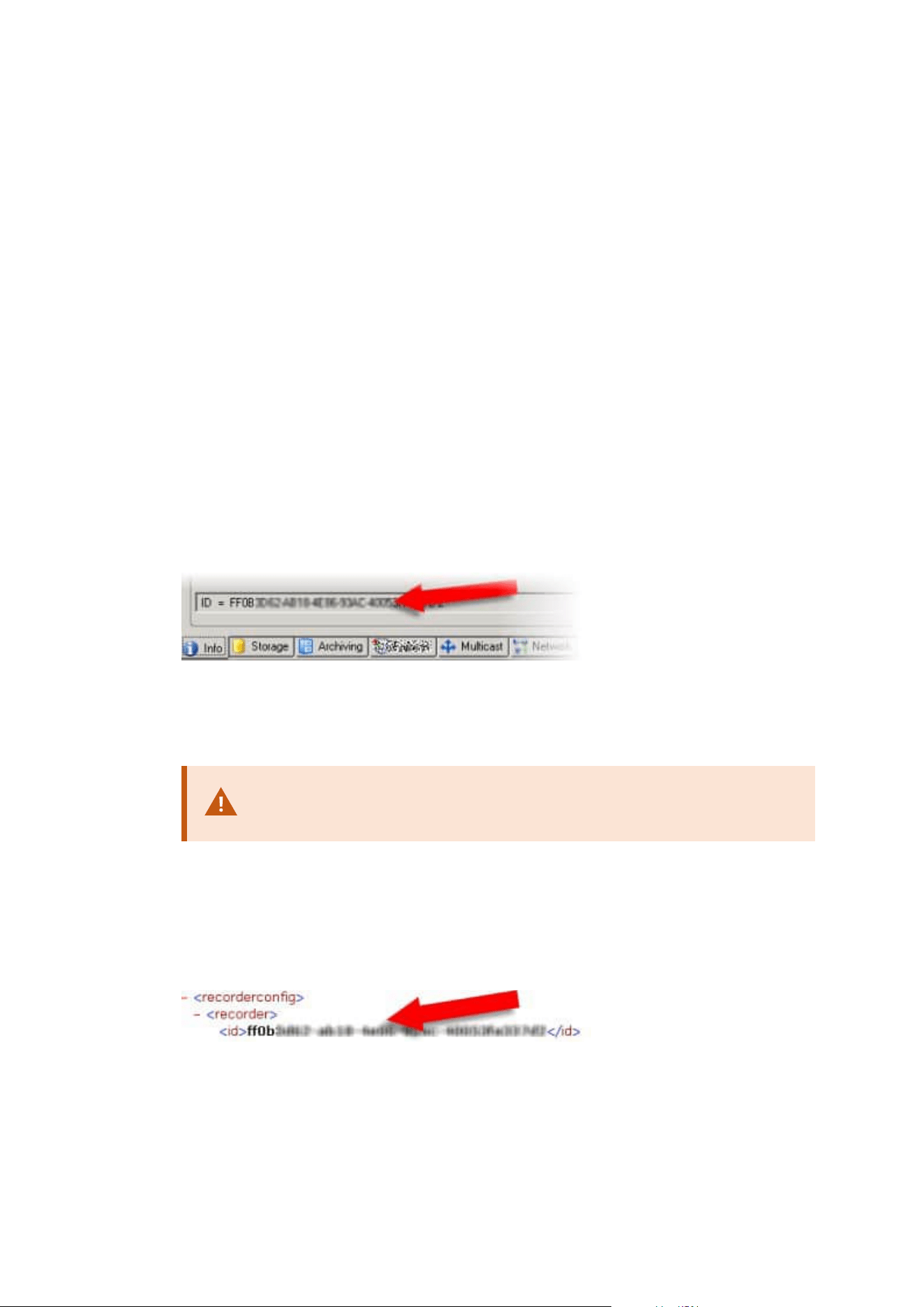
1. Make a backup of your system configuration. This is identical to making a scheduled backup. See also
Back up system configuration with scheduled backup on page 319.
2. Install the new management server on the new server. See scheduled backup, step 2.
3. Restore your system configuration to the new system. See also Restore system configuration from a
scheduled backup on page 319.
Replace a recording server
If a recording server is malfunctioning and you want to replace it with a new server that inherits the settings of
the old recording server:
1. Retrieve the recording server ID from the old recording server:
1. Select Recording Servers, then in the Overview pane select the old recording server.
2. Select the Storage tab.
3. Press and hold down the CTRL key on your keyboard while selecting the Info tab.
4. Copy the recording server ID-number in the lower part of the Info tab. Do not copy the term ID,
only the number itself.
2. Replace the recording server ID on the new recording server:
1. Stop the Recording Server service on the old recording server, then in Windows' Services set the
service's Startup type to Disabled.
It is very important that you do not start two recording servers with
identical IDs at the same time.
2. On the new recording server, open an explorer and go to C:\ProgramData\Milestone\XProtect
Recording Server or the path where your recording server is located.
3. Open the file RecorderConfig.xml.
4. Delete the ID stated in between the tags <id> and </id>.
5. Paste the copied recording server ID in between the tags <id> and </id>. Save the
Administrator manual | XProtect® VMS 2023 R1
323 | Maintenance

RecorderConfig.xml file.
6. Go to the registry: HKEY_LOCAL_MACHINE\SOFTWARE\Wow6432Node\VideoOS\Recorder\Installation.
7. Open RecorderIDOnMachine and change the old recording server ID with the new ID.
3. Register the new recording server on the management server. To do that, right- click the Recording
Server Manager tray icon and click Register. For more information, see Register a recording server on
page 185.
4. Restart the Recording Server service. When the new Recording Server service starts up, it has inherited
all settings from the old recording server.
Move hardware
You can move hardware between recording servers that belong to the same site. After a move, the hardware
and its devices run on the new recording server and new recordings are stored on this server. The move is
transparent to the client users.
The recordings on the old recording server remain there until:
l
The system deletes them when the retention time expires. Recordings that someone has protected with
Evidence Lock (see Evidence locks (explained) on page 70) is not deleted until the evidence lock's
retention time expires. You define the retention time for evidence locks when you create them.
Potentially the retention time never expires
l
You delete them from each device's new recording server on the Record tab
If you try to remove a recording server that still contains recordings, you receive a warning.
If you move hardware to a recording server that currently has no hardware added to it,
the client users must log out and log in to receive data from the devices.
You can use the move hardware feature to:
l
Load balance: If, for example, the disk on a recording server is overloaded, you can add a new
recording server and move some of your hardware
l
Upgrade: If you, for example, have to replace the server that hosts the recording server with a newer
model, you can install a new recording server and move the hardware from the old server to the new
server
l
Replace a defective recording server: If, for example, the server is offline and will never come online
again, you can move the hardware to other recording servers and thereby keep the system running. You
cannot access the old recordings. For more information, see Replace a recording server on page 323.
Administrator manual | XProtect® VMS 2023 R1
324 | Maintenance

Remote recordings
When you move hardware to another recording server, the system cancels ongoing or scheduled retrievals
from interconnected sites or edge storages on cameras. The recordings are not deleted, but the data is not
retrieved and saved in the databases as expected. You receive a warning if this is the case. For the XProtect
Smart Client user, who has started a retrieval when you initiate moving the hardware, the retrieval fails. The
XProtect Smart Client user is notified and can try again later.
If someone has moved hardware on a remote site, you must manually synchronize the central site with the
Update hardware option to reflect the new configuration of the remote site. If you do not synchronize, the
moved cameras remain disconnected on the central site.
Move hardware (wizard)
To move hardware from one recording server to another, run the Move hardware wizard. The wizard takes
you through the necessary steps to complete a move for one or more hardware devices.
Requirements
Before you start the wizard:
l
Make sure that the new recording server can access the physical camera via the network
l
Install a recording server that you want to move hardware to (see Installing through Download
Manager (explained) on page 156 or Install a recording server silently on page 165)
l
Install the same device pack versions on the new recording server that you run on the existing server
(see Device drivers (explained) on page 137)
To run the wizard:
1. In the Site Navigation pane, select Recording Servers.
2. In the Overview pane, right-click the recording server you want to move hardware from or right-click a
specific hardware device.
3. Select Move Hardware.
If the recording server that you move hardware from is disconnected, an error
message appears. You should only choose to move hardware from a
disconnected recording server if you are sure that it will never come online again.
If you move hardware anyway and the server comes back online, you risk an
unexpected behavior from the system due to having the same hardware running
on two recording servers for a period. Possible issues are, for example, license
errors or events that are not sent to the correct recording server.
4. If you started the wizard from the recording server level, the Select the hardware you want to move
page appears. Select the hardware devices you want to move.
Administrator manual | XProtect® VMS 2023 R1
325 | Maintenance
5. On the Select the recording server you want to move the hardware to page, select from the list of
recording servers installed on this site.
6. On the Select the storage you want to use for future recordings page, the storage usage bar
indicates the free space in the recording database for live recordings only, not the archives. The total
retention time is the retention period for both the recording database and the archives.
7. The system processes your request.
8. If the move was successful, click Close. If you select the new recording server in the Management
Client, you can see the moved hardware and now recordings are stored on this server.
If the move failed, you can troubleshoot the issue below.
In an interconnected system, you must manually synchronize the central site
after moving hardware on a remote site to reflect the changes you, or another
system administrator, made at the remote site.
Move hardware troubleshooting
If a move did not succeed, one of the following reasons can be the cause:
Error type Troubleshooting
The recording server is not connected
or in failover mode.
Make sure that the recording server is online. You may need to
register it.
If the server is in failover mode, wait and try again.
The recording server is not the latest
version.
Update the recording server so it runs the same version as the
management server.
The recording server could not be
found in the configuration.
Make sure that the recording server has not been removed.
Updating the configuration or
communication with the configuration
database failed.
Make sure that your SQL Server and database are connected
and running.
Stopping the hardware on the current
recording server failed
Maybe another process has locked the recording server, or the
recording server is in error mode.
Administrator manual | XProtect® VMS 2023 R1
326 | Maintenance

Error type Troubleshooting
Make sure that the recording server is running and try again.
The hardware does not exist.
Make sure that the hardware you try to move has not
simultaneously been removed from the system by another
user. The scenario is quite unlikely.
The recording server that hardware
was moved from is back online, but you
chose to ignore it when it was offline.
Most likely, you have accepted that the old recording server will
never get online again when you started the Move Hardware
wizard, but during the move, the server came online.
Start the wizard again and select No when you are asked to
confirm if the server comes online again.
The source recording storage is
unavailable.
You are trying to move hardware with devices configured with
a recording storage which is currently offline.
A recording storage is offline if the disk is offline or otherwise
unavailable.
Make sure that the recording storage is online and try again.
All recording storages on the target
recording server must be available.
You are trying to move hardware to a recording server where
one or more recording storages are currently offline.
Make sure that all recording storages on the target recording
server are online.
A recording storage is offline of the disk is offline or otherwise
unavailable.
Replace hardware
When you replace a hardware device on your network with another hardware device, you must know the IP
address, port, user name and password of the new hardware device.
If you have not enabled automatic license activation (see Automatic license activation
(explained) on page 110 and have used all device changes without activation (see Device
changes without activation (explained) on page 111), you must manually activate your
licenses after replacing hardware devices. If the new number of hardware devices
exceeds your total number of device licenses, you have to purchase new device licenses.
Administrator manual | XProtect® VMS 2023 R1
327 | Maintenance
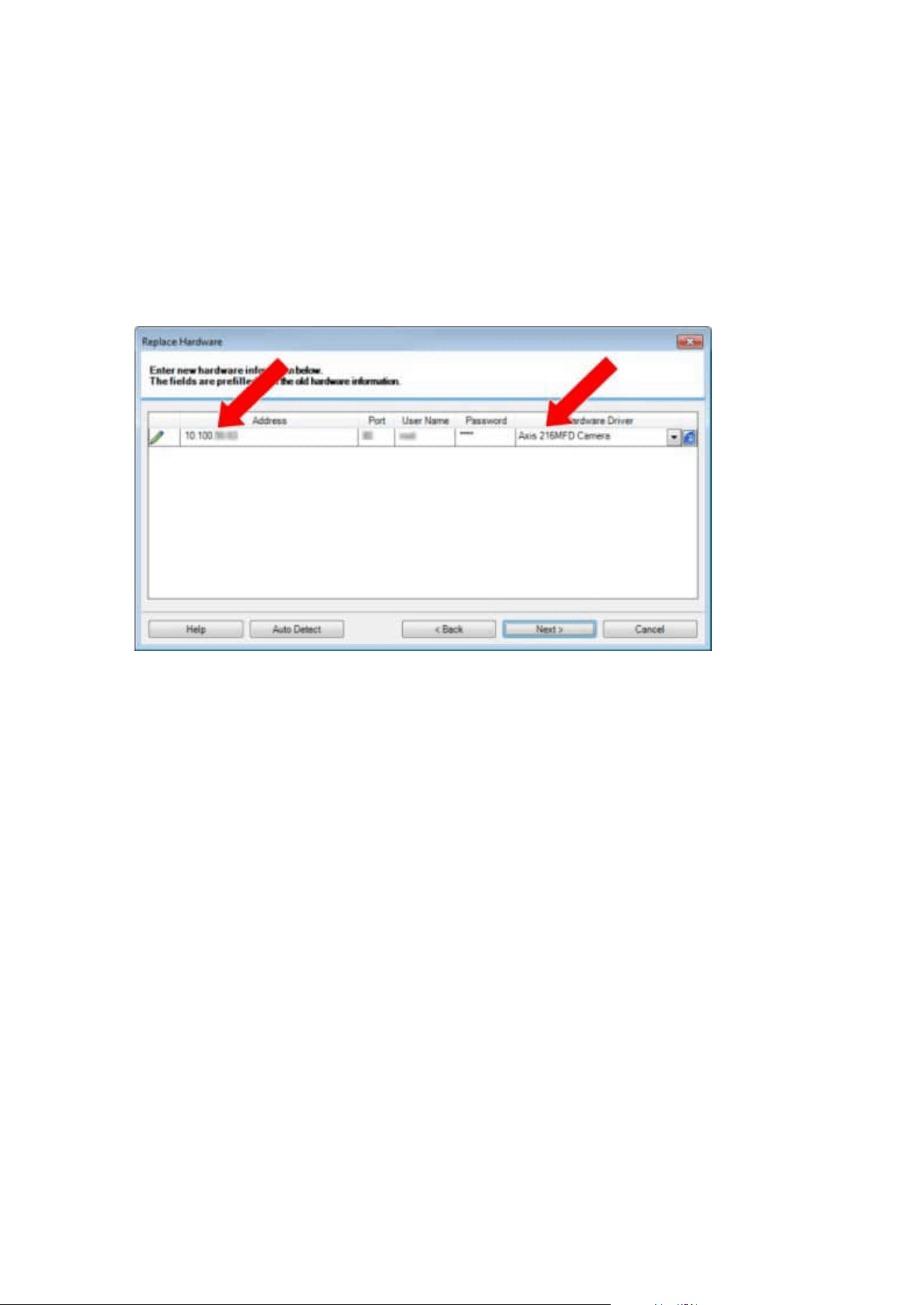
1. Expand the required recording server, right-click the hardware you want to replace.
2. Select Replace Hardware.
3. The Replace Hardware wizard appears. Click Next.
4. In the wizard, in the Address field (marked by red arrow in the image), enter the IP address of the new
hardware. If known, select the relevant driver from the Hardware Driver dropdown list. Otherwise
select Auto Detect. If port, user name or password data is different for the new hardware, correct this
before starting the auto detect process (if needed).
The wizard is pre-filled with data from the existing hardware. If you replace it with a similar hardware
device, you can reuse some of this data - for example, port and driver information.
Administrator manual | XProtect® VMS 2023 R1
328 | Maintenance
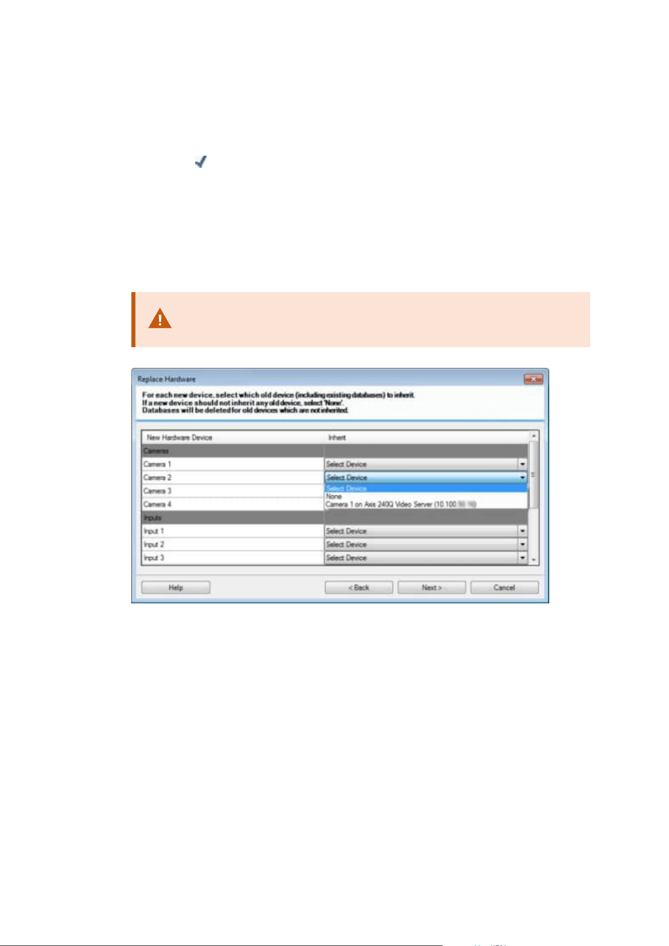
5. Do one of the following:
l
If you selected the required hardware device driver directly from the list, click Next
l
If you selected Auto Detect in the list, click Auto Detect, wait for this process to be successful
(marked by a
to the far left), click Next
This step is designed to help you map devices and their databases, depending on the number of
individual cameras, microphones, inputs, outputs and so on attached to the old hardware device
and the new respectively.
It is important to consider how to map databases from the old hardware device to databases of
the new hardware device. You do the actual mapping of individual devices by selecting a
corresponding camera, microphone, input, output or None in the right-side column.
Make sure to map all cameras, microphones, inputs, outputs, etc.
Contents mapped to None, are lost.
Administrator manual | XProtect® VMS 2023 R1
329 | Maintenance
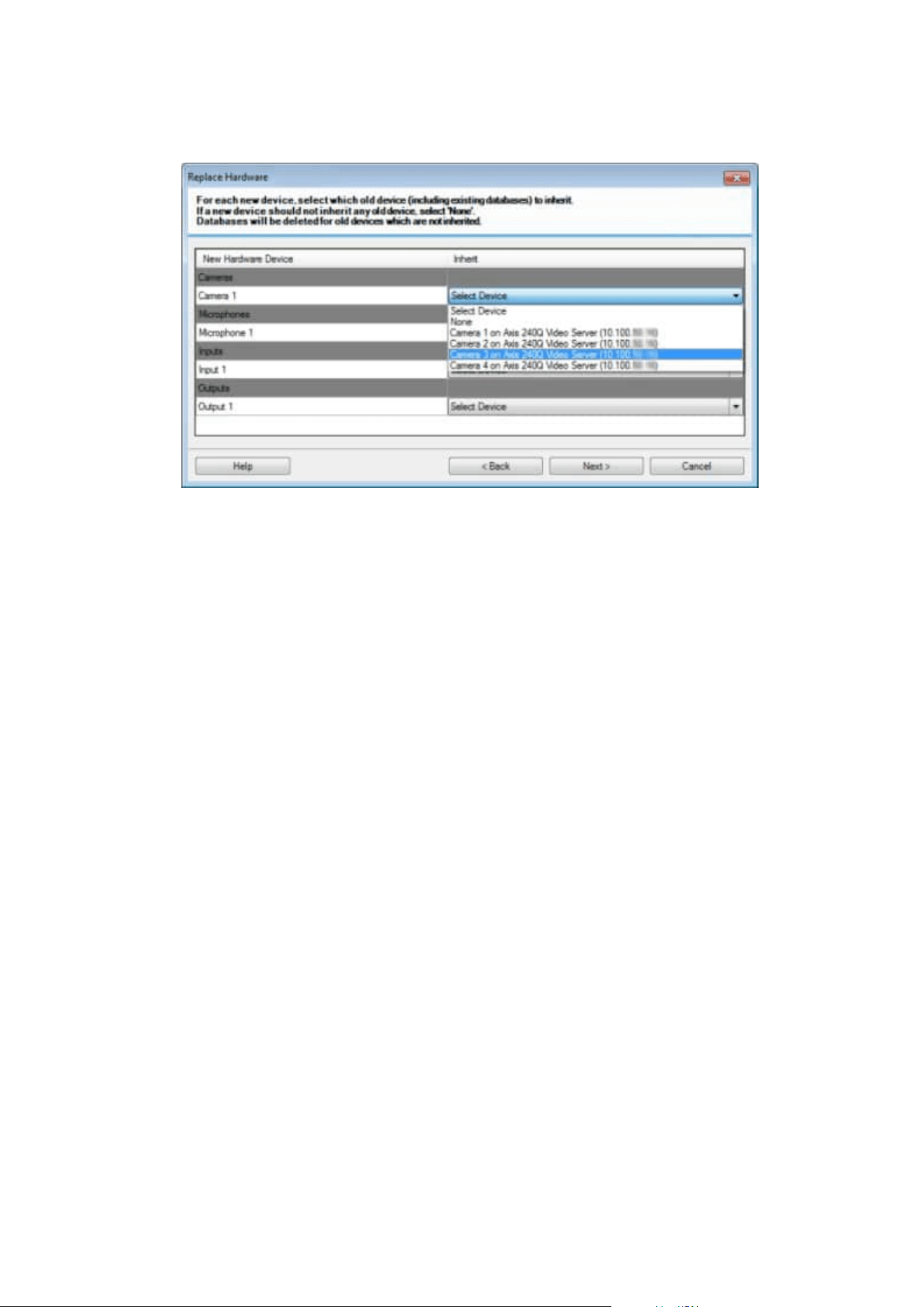
Example of the old hardware device having more individual devices than the new one:
Click Next.
6. You are presented with a list of hardware to be added, replaced or removed. Click Confirm.
7. Final step is a summary of added, replaced and inherited devices and their settings. Click Copy to
Clipboard to copy contents to the Windows clipboard or/and Close to end the wizard.
Update your hardware data
To make sure that your hardware device and the system are using the same firmware version, you need to
manually update the hardware data for the hardware device in the Management Client. Milestone
recommends that you update the hardware data after every firmware update to your hardware device.
To get the latest hardware data:
1. In the Site Navigation pane, select Recording Servers.
2. Expand the required recording server, then select the hardware that you want to get the latest
information for.
3. In the Properties pane on the Info tab, click the Update button in the Hardware data last updated
field.
4. The wizard checks if the system is running the latest firmware for the hardware.
Select Confirm to update the information in the Management Client. When the update is complete, The
current firmware version for the hardware device that is detected by the system appears in the
Firmware version field on the Info tab.
Administrator manual | XProtect® VMS 2023 R1
330 | Maintenance
Managing the SQL Server and databases
Changing the SQL Server and database addresses (explained)
When you install a system as a trial, or if you restructure a large installation, you may need to use a different
SQL Server and database.
You can change the address of the SQL Server and database used by the management server and by the event
server, and the address of the SQL Server and database used by the log server, the XProtect Incident Manager
server and the IDP server. The only limitation is that you cannot change the management server and the event
server's SQL addresses at the same time as the log server's SQL address. You can do it one after another.
You must change the SQL Server and database addresses locally on the computers where you have installed
the servers. If your management server and event server are installed on separate computers, you must
update the addresses on both computers.
You must copy the SQL databases before you proceed.
Change the log server's SQL Server and database
To change the SQL location for the Log Server, do the following:
Before making any changes to the registry, make a registry backup.
1. Ensure that the user running the Log Server application pool is the owner (DBO) of the log server
database.
2. Update the ConnectionString value in the Windows Registry to include the new location and name of
the log server. The value can be found and modified under:
HKEY_LOCAL_MACHINE\SOFTWARE\VideoOS\Server\ConnectionString:
3. Restart the Log Server via Windows Services.
The default database name is: SurveillanceLogServerV2.
Change the management server and the event server's SQL Server and
database
To change the SQL location for the management server and the event server, do the following:
Before making any changes to the registry, make a registry backup.
Administrator manual | XProtect® VMS 2023 R1
331 | Maintenance
1. Stop the services and ensure that the user running the management server and the event server is the
owner (DBO) of the database.
2. Update the ConnectionString values in the Windows Registry to include the new location and name of
the servers. The values can be found and modified under:
HKEY_LOCAL_MACHINE\SOFTWARE\VideoOS\Server\ConnectionString:
3. Restart the Management Server and the XProtect Event Server via Windows Services or from the tray
icons in the notification area.
The default database name is: Surveillance.
The connection strings are: ManagementServer and EventServer.
If the event server is running on a different computer, make the same change there. The event server and the
management server use the same database.
Change the XProtect Incident Manager server's SQL Server and database
Before making any changes to the registry, make a registry backup.
1. Stop the service and ensure that the user running the XProtect Incident Manager server is the owner
(DBO) of the database.
2. Update the ConnectionString value in the Windows Registry to include the new location and name of
the server. The values can be found and modified under:
HKEY_LOCAL_MACHINE\SOFTWARE\VideoOS\Server\ConnectionString:
3. Restart the Incident Manager from the IIS Manager.
The default database name is: Surveillance_IM.
Change the IDP server's SQL Server and database
Before making any changes to the registry, make a registry backup.
1. Stop the service and ensure that the user running the IDP server is the owner (DBO) of the database.
2. Update the ConnectionString value in the Windows Registry to include the new location and name of
the server. The values can be found and modified under:
HKEY_LOCAL_MACHINE\SOFTWARE\VideoOS\Server\ConnectionString:
3. Restart the IDP from the IIS Manager.
The default database name is: Surveillance_IDP.
Administrator manual | XProtect® VMS 2023 R1
332 | Maintenance
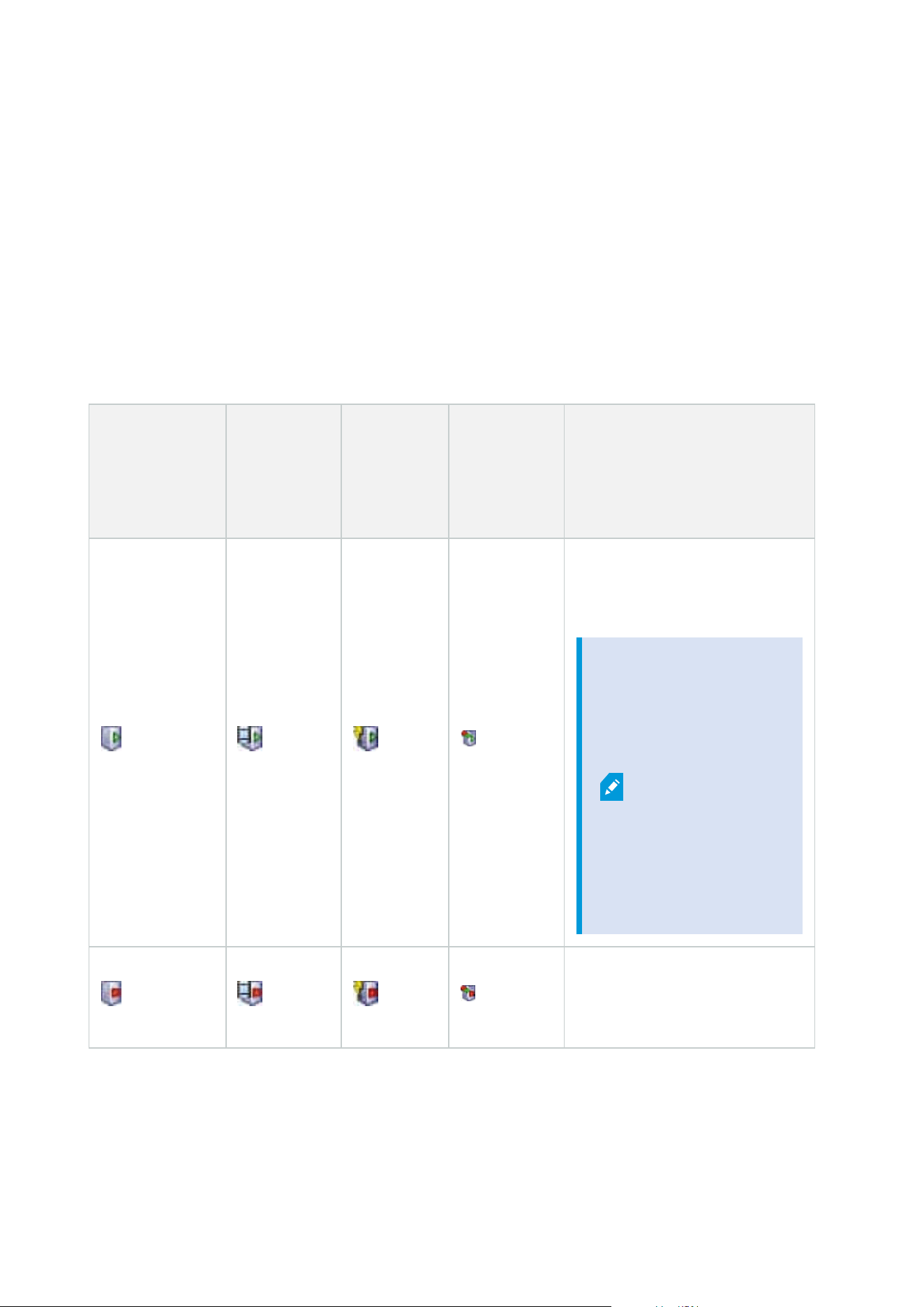
Managing server services
On the computer that runs server services, you find server manager tray icons in the notification area. Through
these icons, you can get information about the services and perform certain tasks. This includes, for example,
checking the state of the services, viewing logs or status messages, and starting and stopping the services.
Server manager tray icons (explained)
The tray icons in the table show the different states of the services running on the management server,
recording server, failover recording server, and event server. They are visible on the computers with the
servers installed, in the notification area:
Management
Server Manager
tray icon
Recording
Server
Managertray
icon
Event
Server
Manager
tray icon
Failover
Recording
Server
Manager
tray icon
Description
Running
Appears when a server service is
enabled and started.
If the
Failover
Recording
Server
service is
running, it
can take
over if the
standard
recording
servers
fails.
Stopped
Appears when a server service has
stopped.
Administrator manual | XProtect® VMS 2023 R1
333 | Maintenance
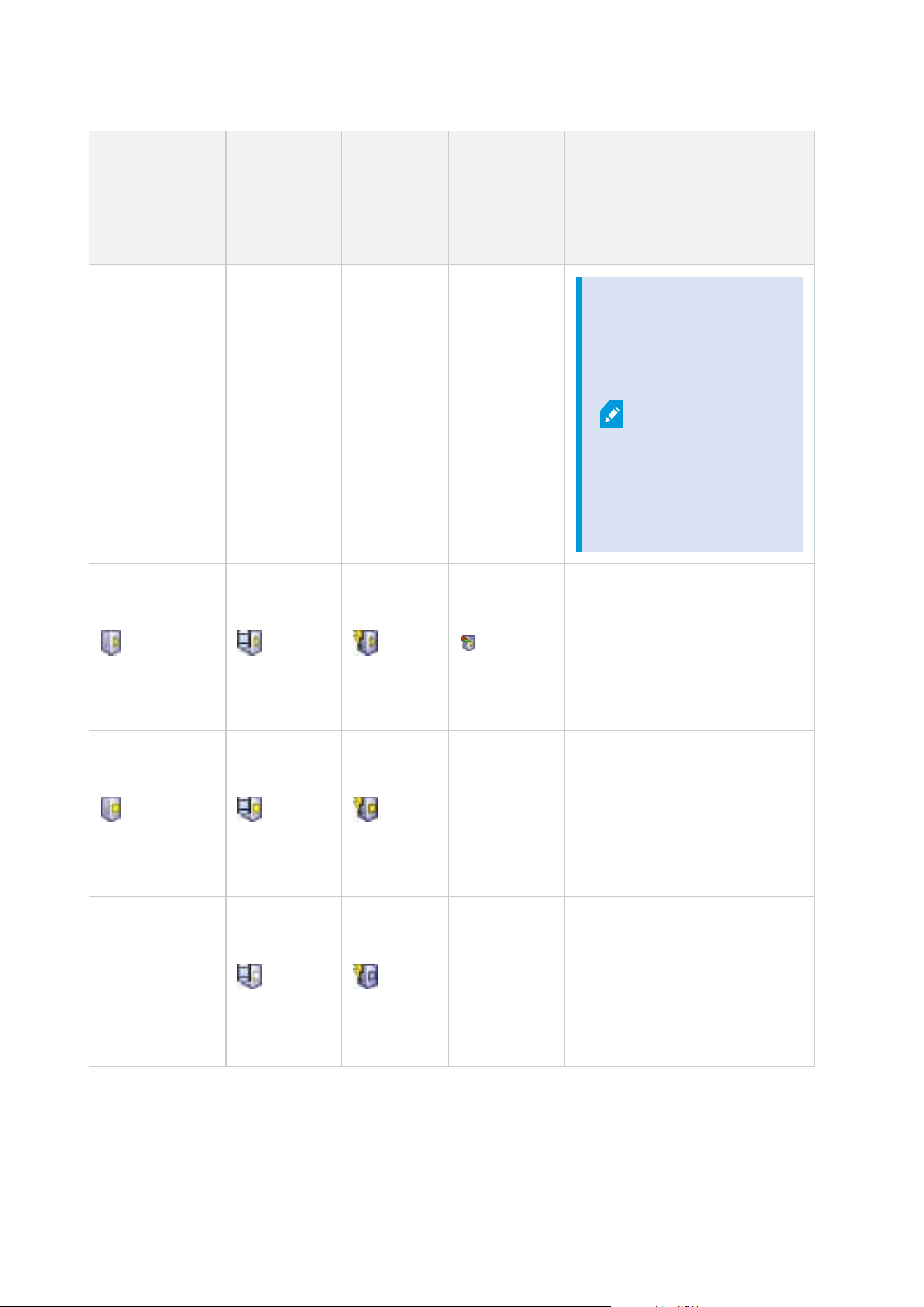
Management
Server Manager
tray icon
Recording
Server
Managertray
icon
Event
Server
Manager
tray icon
Failover
Recording
Server
Manager
tray icon
Description
If the
Failover
Recording
Server
service
stops, it
cannot take
over if the
standard
recording
server fails.
Starting
Appears when a server service is
in the process of starting. Under
normal circumstances, the tray
icon changes after a short while to
Running.
Stopping
Appears when a server service is
in the process of stopping. Under
normal circumstances, the tray
icon changes after a short while to
Stopped.
In indeterminate state
Appears when the server service
is initially loaded and until the first
information is received, upon
which the tray icon, under normal
circumstances, changes to
Administrator manual | XProtect® VMS 2023 R1
334 | Maintenance
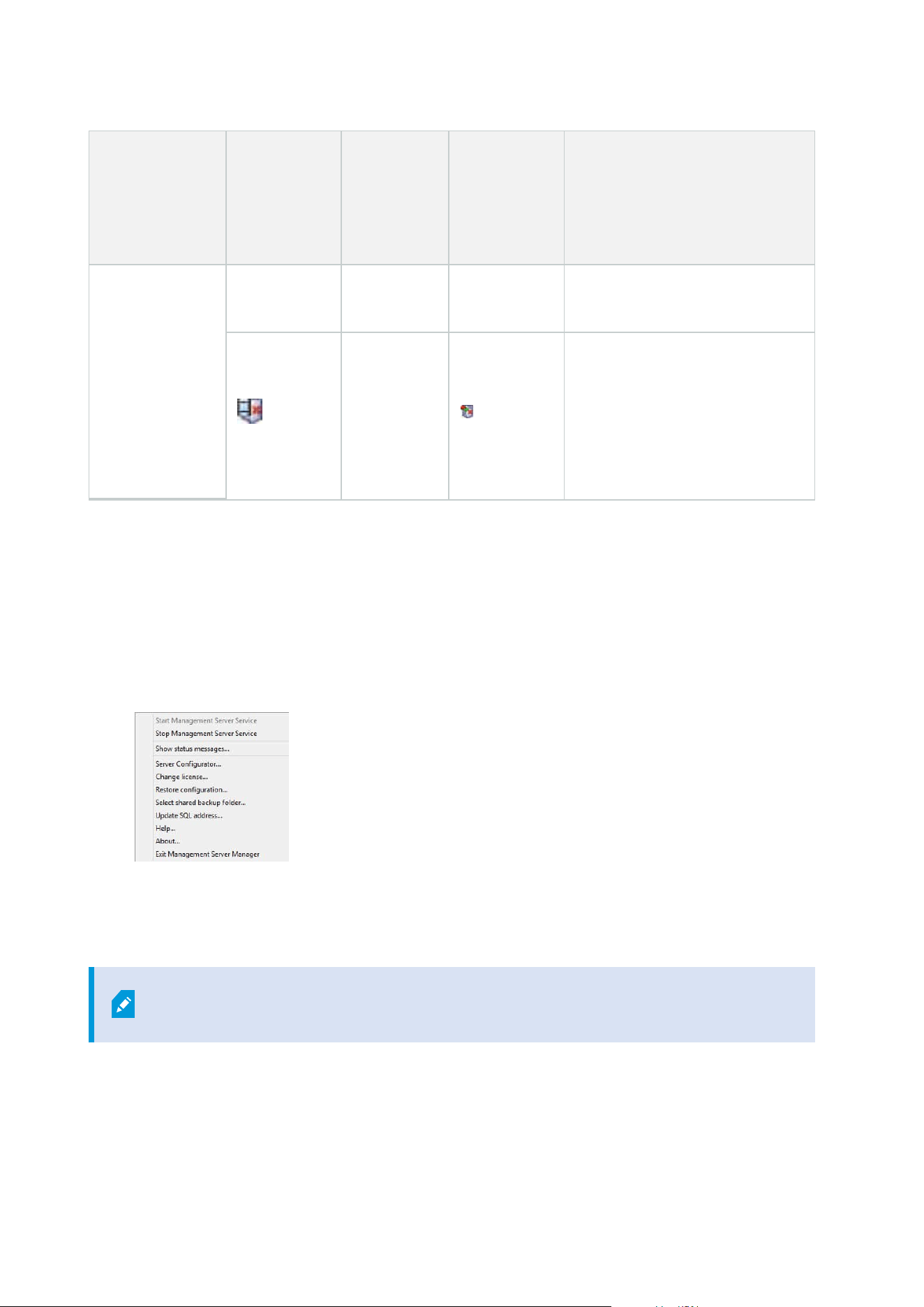
Management
Server Manager
tray icon
Recording
Server
Managertray
icon
Event
Server
Manager
tray icon
Failover
Recording
Server
Manager
tray icon
Description
Starting and afterwards to
Running.
Running offline
Typically appears when the
Recording Server or Failover
recording service is running but
the Management Server service is
not.
Start or stop the Management Server service
The Management Server Manager tray icon indicates the state of the Management Server service, for example
Running. Through this icon, you can start or stop the Management Server service. If you stop the
Management Server service, you cannot use the Management Client.
1. In the notification area, right-click the Management Server Manager tray icon. A context-menu appears.
2. If the service has stopped, click Start Management Server service to start it. The tray icon changes to
reflect the new state.
3. To stop the service, click Stop Management Server service.
For more information about the tray icons, see Server manager tray icons (explained) on
page 333.
Administrator manual | XProtect® VMS 2023 R1
335 | Maintenance
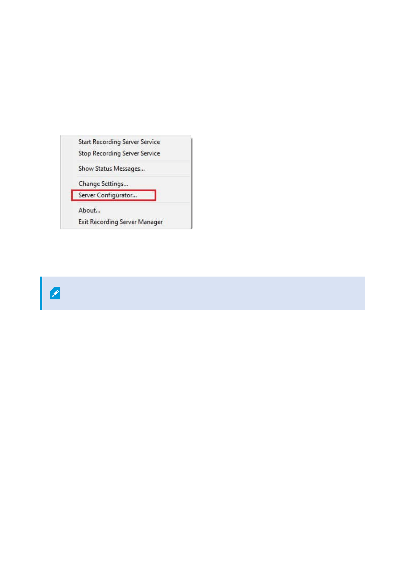
Start or stop the Recording Server service
The Recording Server Manager tray icon indicates the state of the Recording Server service, for example
Running. Through this icon, you can start or stop the Recording Server service. If you stop the Recording
Server service, your system cannot interact with devices connected to the server. This means you cannot view
live video or record video.
1. In the notification area, right-click the Recording Server Manager tray icon. A context-menu appears.
2. If the service has stopped, click Start Recording Server service to start it. The tray icon changes to
reflect the new state.
3. To stop the service, click Stop Recording Server service.
For more information about the tray icons, see Server manager tray icons (explained) on
page 333.
Administrator manual | XProtect® VMS 2023 R1
336 | Maintenance
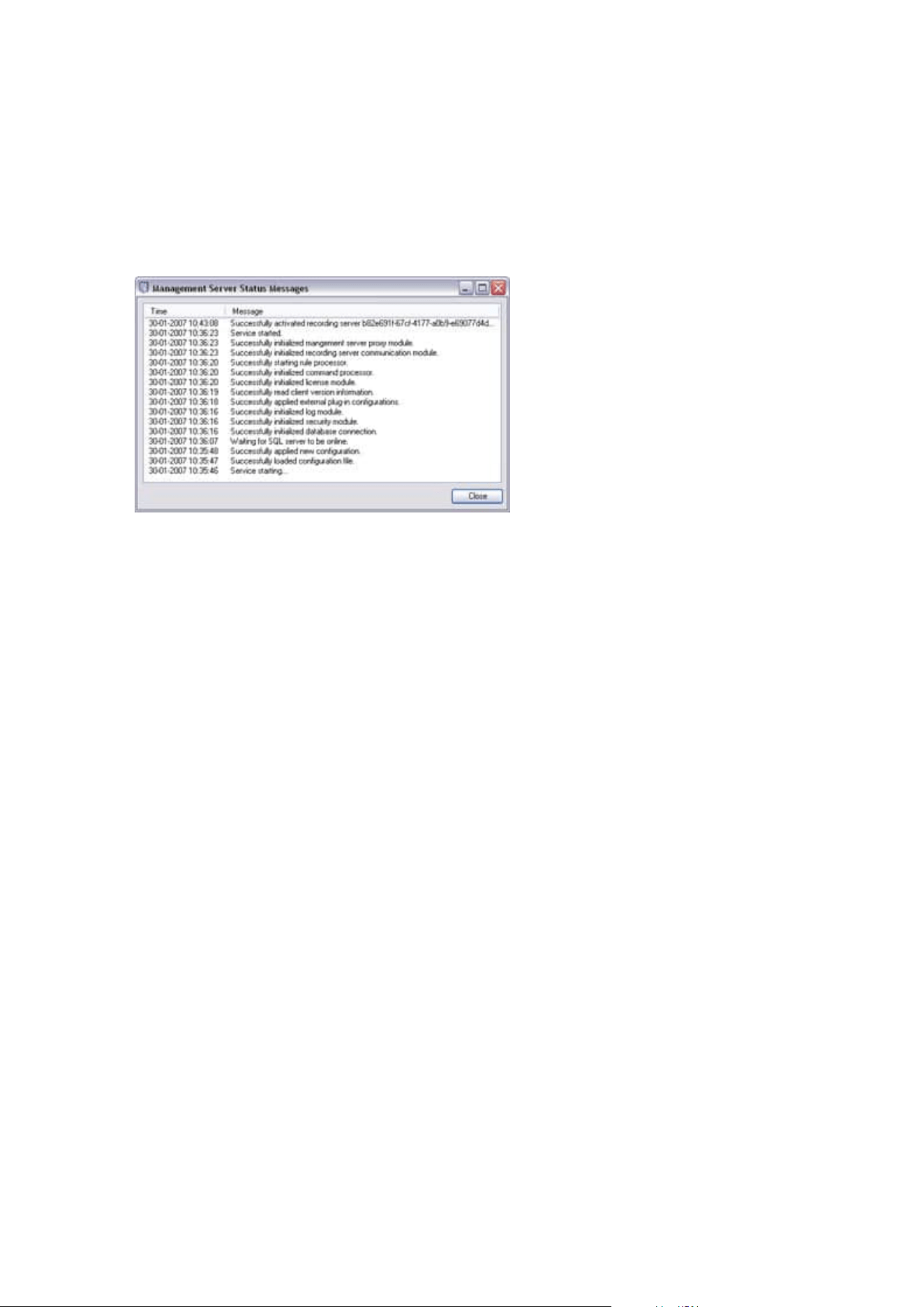
View status messages for Management Server or Recording Server
1. In the notification area, right-click the relevant tray icon. A context-menu appears.
2. Select Show Status Messages. Depending on the server type, either the Management Server Status
Messages or Recording Server Status Messages window appears, listing time-stamped status
messages:
Manage encryption with the Server Configurator
Use the Server Configurator to select certificates on local servers for encrypted communication and register
server services to make them qualified to communicate with the servers.
Open the Server Configurator from either the Windows startup menu, from the management server tray icon
or from the recording server tray icon. See Server Configurator (Utility) on page 385.
For more information, see the certificates guide about how to secure your XProtect VMS installations.
Start, stop, or restart the Event Server service
The Event Server Manager tray icon indicates the state of the Event Server service, for example Running.
Through this icon, you can start, stop, or restart the Event Server service. If you stop the service, parts of the
system will not work, including events and alarms. However, you can still view and record video. For more
information, see Stopping the Event Server service on page 338.
Administrator manual | XProtect® VMS 2023 R1
337 | Maintenance
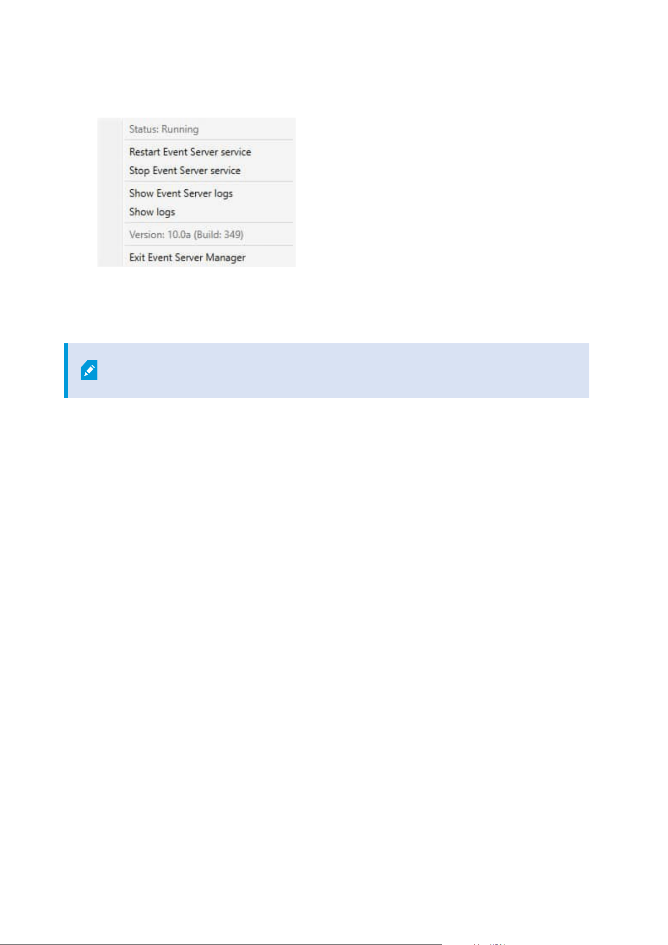
1. In the notification area, right-click the Event Server Manager tray icon. A context-menu appears.
2. If the service has stopped, click Start Event Server service to start it. The tray icon changes to reflect
the new state.
3. To restart or stop the service, click Restart Event Server service or Stop Event Server service.
For more information about the tray icons, see Server manager tray icons (explained) on
page 333.
Stopping the Event Server service
When installing MIP plug-ins in the Event Server, first you must stop the Event Server service and then,
afterward, restart it. While the service is stopped, many areas of the VMS system will not function:
l
No events or alarms are stored in the Event Server. However, system and device events still trigger
actions, for example start recording
l
Add-on products do not work in XProtect Smart Client and cannot be configured from the Management
Client.
l
Analytic events do not work
l
Generic events do not work
l
No alarms are triggered
l
In XProtect Smart Client, map view items, alarm list view items, and the Alarm Manager workspace do
not work
l
MIP plug-ins in the Event Server cannot run
l
MIP plug-ins in Management Client and XProtect Smart Client do not work correctly
View Event Server or MIP logs
You can view time-stamped information about Event Server activities in the Event Server log. Information
about third party integrations is logged in the MIP log in a sub-folder in the Event Server folder.
Administrator manual | XProtect® VMS 2023 R1
338 | Maintenance
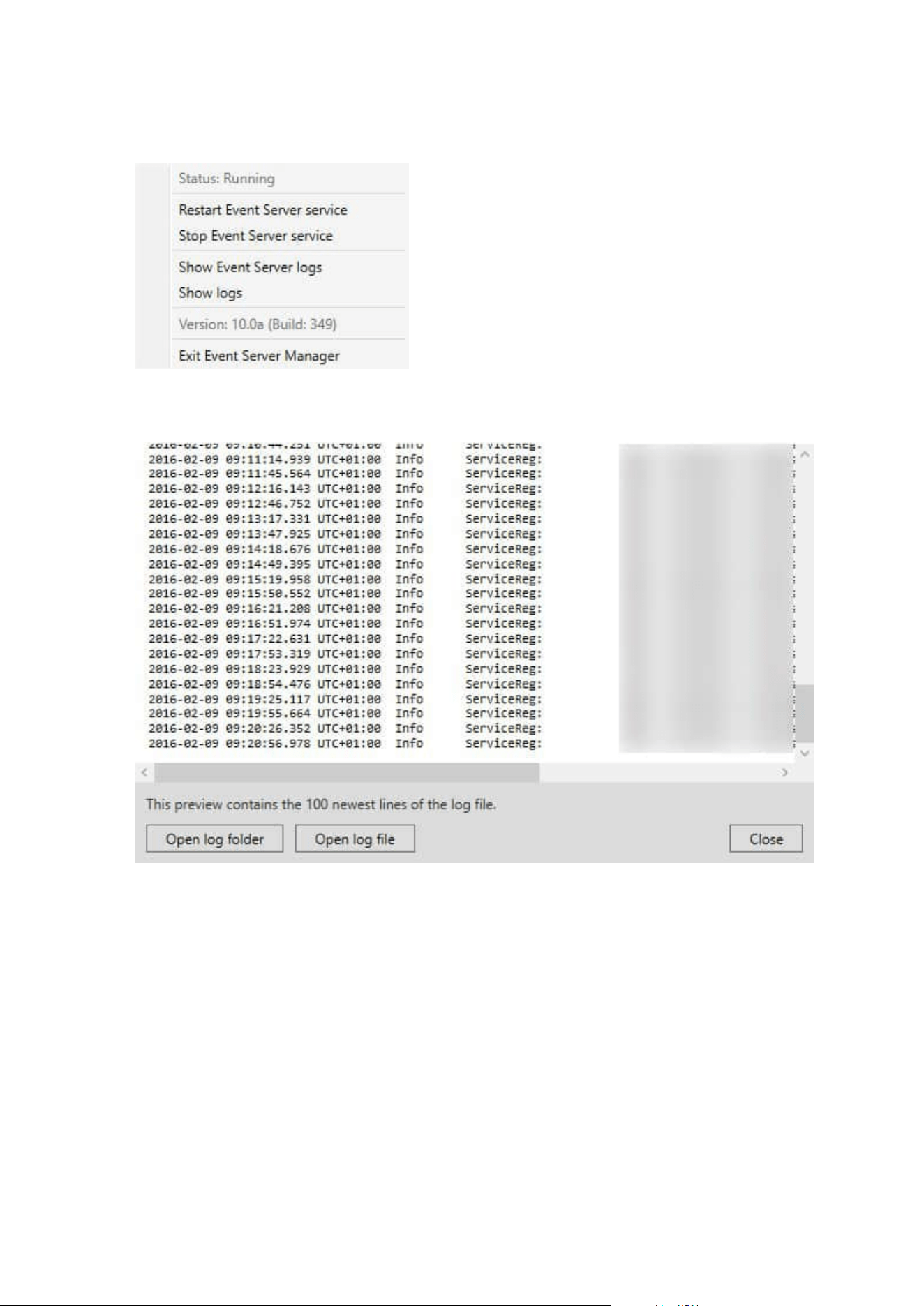
1. In the notification area, right-click the Event Server Manager tray icon. A context-menu appears.
2. To view the 100 most recent lines in the Event Server log, click Show Event Server Logs. A log viewer
appears.
1. To view the log file, click Open log file.
2. To open the log folder, click Open log folder.
3. To view the 100 most recent lines in the MIP log, go back to the context-menu and click Show MIP logs.
A log viewer is displayed.
Administrator manual | XProtect® VMS 2023 R1
339 | Maintenance
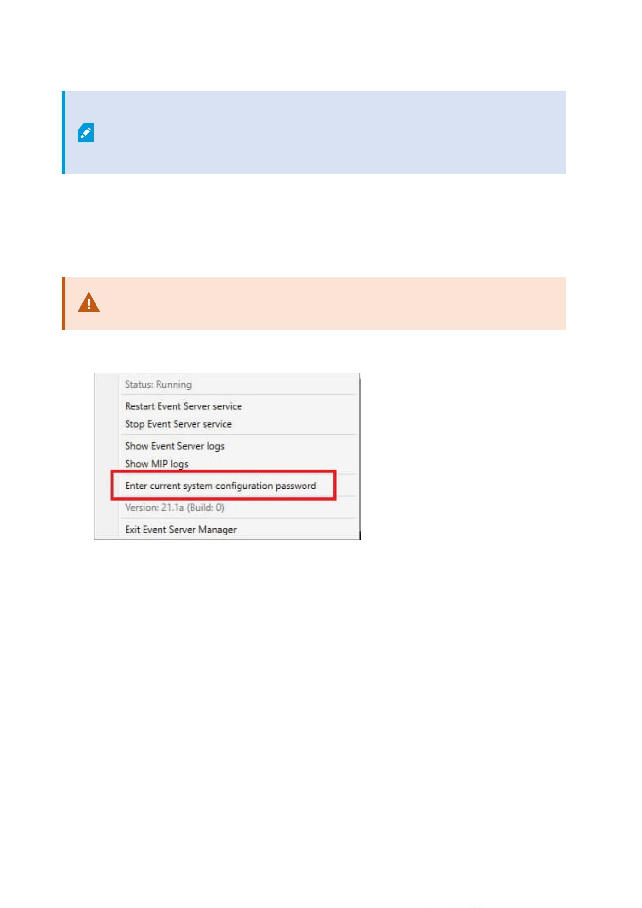
If someone removes the log file from the log directory, the menu items are grayed out.
To open the log viewer, first you need to copy the log file back into its folder:
C:\ProgramData\Milestone\XProtect Event Server\logs or C:\ProgramData\Milestone\XProtect
Event Server\logs\MIPLogs.
Enter current system configuration password
If the system configuration password has been changed in the management server, you must enter the
current system configuration password in the event server, too.
If you don't enter the current password in the event server, then system components,
such as access control, will stop working.
1. In the notification area, right-click the Event Server Manager tray icon. A context-menu appears.
2. To enter the current system configuration password, click Enter current system configuration
password. A window appears.
3. Enter the same system configuration password that has been entered in the management server.
Managing registered services
Occasionally, you have servers and/or services which should be able to communicate with the system even if
they are not directly part of the system. Some services, but not all, can register themselves automatically in the
system. Services that can automatically be registered are:
l
Event Server service
l
Log Server service
Automatically registered services are displayed in the list of registered services.
Administrator manual | XProtect® VMS 2023 R1
340 | Maintenance
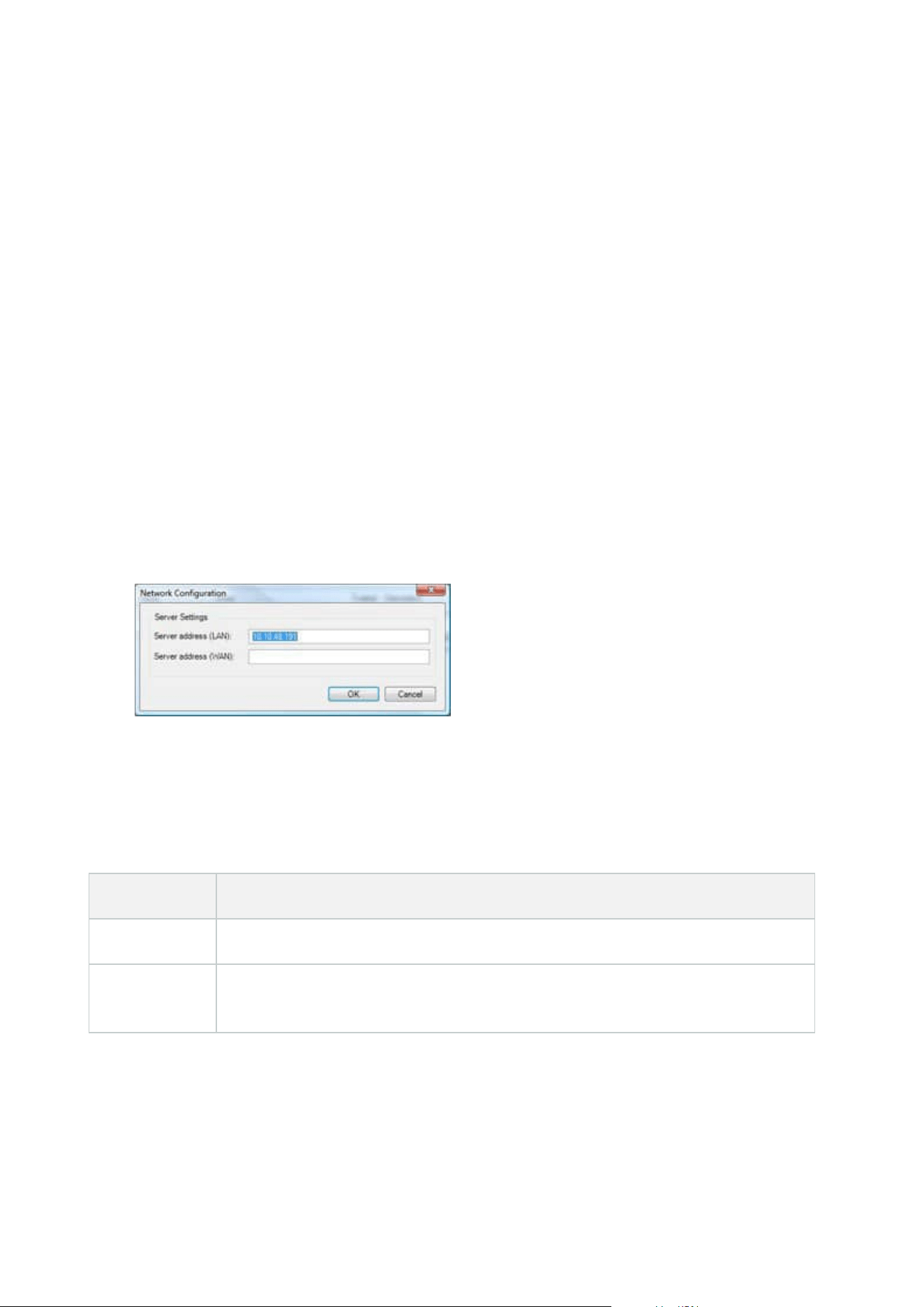
You can manually specify servers/services as registered services in the Management Client.
Add and edit registered services
1. In the Add/Remove Registered Services window, click Add or Edit, depending on your needs.
2. In the Add Registered Service or Edit Registered Service window (depending on your earlier selection),
specify or edit settings.
3. Click OK.
Manage network configuration
With the network configuration settings, you can specify the management server's server LAN and WAN
addresses so the management server and the trusted servers can communicate.
1. In the Add/Remove Registered Services window, click Network.
2. Specify the LAN and/or WAN IP address of the management server.
If all involved servers (both the management server and the trusted servers) are on your local network,
you can simply specify the LAN address. If one or more involved servers access the system through an
internet connection, you must also specify the WAN address.
3. Click OK.
Registered services properties
In the Add Registered Service or Edit Registered Service window, specify the following:
Component Requirement
Type Prefilled field.
Name
Name of the registered service. The name is only used for display purposes in the
Management Client.
Administrator manual | XProtect® VMS 2023 R1
341 | Maintenance

Component Requirement
URLs
Click Add to add the IP address or hostname of the registered service. If specifying a
hostname as part of a URL, the host must exist and be available on the network. URLs
must begin with http:// or https:// and must not contain any of the following characters:
< > & ' " * ? | [ ] ".
Example of a typical URL format: http://ipaddress:port/directory (where port and
directory are optional). You can add more than one URL if required.
Trusted
Select if the registered service should be trusted immediately (this is often the case, but
the option gives you the flexibility to add the registered service and then mark it as
trusted by editing the registered service later).
Changing the trusted state also changes the state of other registered services sharing
one or more of the URLs defined for the relevant registered service.
Description
Description of the registered service. The description is only used for display purposes
in the Management Client.
Advanced
When a service is advanced, it has specific URI schemes (for example, HTTP, HTTPS,
TCP, or UDP) that need to be set up for each host address you define. A host address
therefore has multiple endpoints, each with its own scheme, host address and IP port
for that scheme.
Removing device drivers (explained)
If you no longer require device drivers on your computer, you can delete the device packs from your system.
To do so, follow the standard Windows procedure for removing programs.
If you have multiple device packs installed and have problems deleting the files, you can use the script in the
device pack installation folder to delete them completely.
If you remove device drivers, the recording server and the camera devices cannot communicate any longer. Do
not remove device packs when you upgrade because you can install a new version on top of an old one. Only if
you uninstall the entire system may you remove the device pack.
Administrator manual | XProtect® VMS 2023 R1
342 | Maintenance
Remove a recording server
If you remove a recording server, all configuration specified in the Management Client is
removed for the recording server, including all of the recording server's associated
hardware (cameras, input devices, and so on).
1. Right-click the recording server you want to remove in the Overview pane.
2. Select Remove Recording Server.
3. If you are sure, click Yes.
4. The recording server and all of its associated hardware are removed.
Delete all hardware on a recording server
When you delete hardware, all recorded data related to the hardware is deleted
permanently.
1. Right-click the recording server on which you want to delete all hardware.
2. Select Delete All Hardware.
3. Confirm the deletion.
Changing the host name of the management server computer
If the management server is addressed by its fully qualified domain name (FQDN) or its host name, a change to
the host name of the computer will have implications within XProtect that must be considered and dealt with.
In general, a change of the host name of a management server should be planned for
carefully due to the amount of clean-up that might be required afterwards.
In the following sections you can get an overview of some of the implications of a change of a host name.
The validity of certificates
Certificates are used to encrypt communication between services, and the certificates are installed on all the
computers that run one or more of the XProtect services.
Depending on how certificates are created, they can be related to the computer they are installed on, and they
will only be valid as long as the computer name stays the same.
For more information about how to create certificates, see Introduction to certificates.
Administrator manual | XProtect® VMS 2023 R1
343 | Maintenance

If a computer name is changed, the certificates that are used may become invalid, and the XProtect VMS
cannot be started. To get the system up and running again, complete these steps:
l
Create new certificates and reinstall them on all of the computers in the environment.
l
Apply the new certificates, using the Server Configurator, on each of the computers to enable
encryption with the new certificates.
This will trigger the registration of the new certificates and get the system up and running again.
Loss of customer data properties for registered services
If you complete a registration using the Server Configurator after, for example, a change to the management
server address, any edits to information for the registered services will be overwritten. So, if you have changed
information for the registered services, the changes must be applied again for all the services that are
registered to the management server on the computer with the changed name.
The information that can be edited for registered services is located under Tools > Registered Services > Edit:
l
Trusted
l
Advanced
l
External flag
l
Any manually added URL
In Milestone Customer Dashboard, the host name will appear unchanged
Milestone Customer Dashboard is a free online tool for Milestone partners and resellers to manage and
monitor Milestone software installations and licenses.
A change of the name of the management server on a system that is connected to Milestone Customer
Dashboard will not automatically be reflected in Milestone Customer Dashboard.
The old host name will appear in Milestone Customer Dashboarduntil a new license activation is completed.
The name change, however, will not break anything in Milestone Customer Dashboard and once a new
activation takes place, the record is updated in the database with the new host name. For more information
about Milestone Customer Dashboard, see Milestone Customer Dashboard (explained).
A host name change can trigger the change of the SQL Server address
If an SQL Server is located on the same computer as the management server, and the name of this computer is
changed, the address of the SQL Server will change as well. This means that the SQL Server address will have
to be updated for components located on different computers as well as for components on the local
computer that use the computer name rather than localhost to connect to the SQL Server. This specifically
applies to the Event Server which uses the same database as the Management Server. It might also apply to
the Log Server which uses a different database but very likely on the same SQL server.
Administrator manual | XProtect® VMS 2023 R1
344 | Maintenance

For more information about how to update SQL addresses for the Event Server and the Management Server,
see Change the management server and event server's SQL addresses. The SQL server address for the Log
Server must be updated in the Windows Registry.
Host name changes in a Milestone Federated Architecture
Changes to the name of a computer that resides within a Milestone Federated Architecture setup will have the
following implications, and this applies both when sites are connected inside work groups and across domains.
The host of the site is the root node in the architecture
If you change the name of the computer that the central site within the architecture is running on, all child
nodes will be re-attached automatically to the new address. So in this case, a rename will not require any
actions.
The host of the site is a child node in the architecture
To avoid connection issues when changing the name of a computer that one or more federated sites are
running on, you must add an alternate address to the affected site, before the computer is renamed. The
affected site being the node whose host computer will be renamed. For more information about connection
issues due to unprepared or unpredicted host name changes and how to resolve the problems, see Issue: A
parent node in a Milestone Federated Architecture setup cannot connect to a child node.
The alternate address must be added in the Properties pane in either the Site Navigation or the Federated
Site Hierarchy pane. The following prerequisites must be met:
l
The alternate address must be added to be available before the host computer is renamed
l
The alternate address must reflect the future name of the host computer (when renamed)
See Set site properties for information about how to access the Properties pane.
To ensure the smoothest update possible, stop the Management Client on the node that
serve as a parent node to the one whose host name will change. Otherwise, stop and
restart the client after the computer has been renamed. For more information, see Start
or stop the Management Server service.
Also, make sure the alternate address you provided is reflected in the Federated Site
Hierarchy pane at your central site and if not, stop and restart the Management Client.
Once the host has been renamed, and you have restarted the computer, the federated site will automatically
switch to the new address.
Administrator manual | XProtect® VMS 2023 R1
345 | Maintenance

Managing server logs
The following are the types of server logs:
l
System log
l
Audit log
l
Rule-triggered logs
These are used to log the usage of the system. These logs are available in the Management Client under
Server logs.
For information about logs used for troubleshooting and investigating software errors, see Debug logs
(explained) on page 350.
Identify user activity, events, actions and errors
Use logs to get a detailed record of user activity, events, actions, and errors in the system.
To see logs in the Management Client, go to the Site Navigation pane and select Server Logs.
Log type What is logged?
System logs System-related information
Audit logs User activity
Rule-triggered logs
Rules in which users have specified the Make
new <log entry> action. For more information
about the <log entry> action, see Actions and
stop actions.
To see logs in a different language, see General tab (options) on page 366 under Options.
To export logs as comma-separated values (.csv) files, see Export logs.
To change log settings, see Server Logs tab (options) on page 369.
Filter Logs
In each log window, you can apply filters to see log entries from, for example, a specific time span, a device, or
a user.
Administrator manual | XProtect® VMS 2023 R1
346 | Maintenance
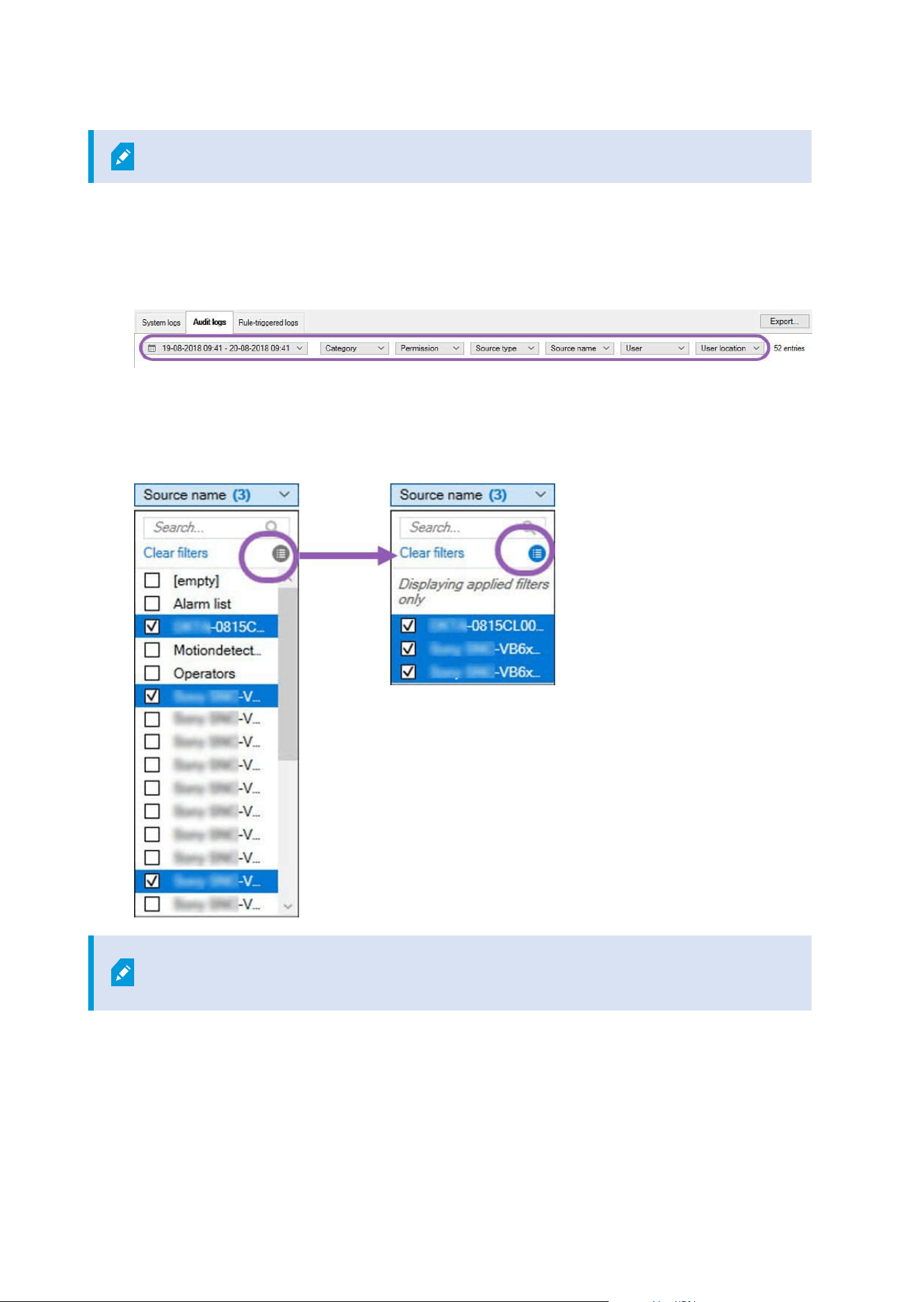
Filters are generated from the log entries that are currently visible in the user interface.
1. In the Site Navigation pane, select Server Logs. By default, the System logs tab appears.
To navigate between log types, select a different tab.
2. Under the tabs, select a filter group, for example, Category, Source type, or User.
A list of filters appears. A list of filters shows maximum 1000 filters.
3. Select a filter to apply it. Select the filter again to remove it.
Optional: In a list of filters, select Display applied filters only to see only the filters that you applied.
When you export logs, the contents of your export change depending on the filters that
you apply. For information about your export, see Export logs.
Administrator manual | XProtect® VMS 2023 R1
347 | Maintenance
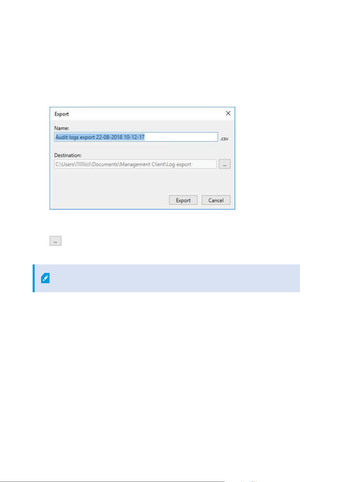
Export logs
Exporting logs helps you to, for example, save log entries beyond the log retention period. You can export logs
as comma-separated values (.csv) files.
To export a log:
1. Select Export in the upper-right corner. The Export window appears.
2. In the Export window, in the Name field, specify a name for the log file.
3. By default, exported log files are saved in your Log export folder. To specify a different location, select
to the right of the Destination field.
4. Select Export to export the log.
The contents of your export change depending on the filters that you apply. For
information about your export, see Filter logs.
Search logs
To search a log, use Search criteria in the top part of the log pane:
1. Specify your search criteria from the lists.
2. Click Refresh to make the log page reflect your search criteria. To clear your search criteria, and return
to viewing all of the log's content, click Clear.
You can double-click any row to have all details presented in a Log Details window. In this way you can also
read the log entries that contain more text than can be displayed in a single line.
Administrator manual | XProtect® VMS 2023 R1
348 | Maintenance

Change log language
1. At the bottom part of the log pane, in the Show log in list, select the wanted language.
2. The log is displayed in the selected language. Next time your open the log, it is reset to the default
language.
Allow 2018 R2 and earlier components to write logs
The 2018 R3 version of the log server introduces authentication for added security. This prevents 2018 R2 and
earlier components from writing logs to the log server.
Affected components:
l
XProtect Smart Client
l
XProtect LPR Plug-in
l
LPR Server
l
Access Control Plug-in
l
Event Server
l
Alarm Plug-in
If you're using the 2018 R2 or earlier version of any of the components listed above, you must decide whether
or not to allow the component to write logs to the new log server:
1. Select Tools > Options.
2. In the Options dialog box, at the bottom of the Server Logs tab, find the Allow 2018 R2 and earlier
components to write logs check box.
l
Select the check box to allow 2018 R2 and earlier components to write logs
l
Clear the check box to not allow 2018 R2 and earlier components to write logs
Administrator manual | XProtect® VMS 2023 R1
349 | Maintenance
Troubleshooting
Debug logs (explained)
Debug logs are used to identify defects and flaws in the system.
For information about logs used for system usage, see Managing server logs on page 346.
The following are the location of the log files in the XProtect installation:
l
C:\ProgramData\Milestone\IDP\Logs
This is accessible only to IIS user and administrators. If the IIS user is changed,
these permissions must be updated.
l
C:\ProgramData\Milestone\MIPSDK
l
C:\ProgramData\Milestone\XProtect Data Collector Server\Logs
l
C:\ProgramData\Milestone\XProtect Event Server\Logs
l
C:\ProgramData\Milestone\XProtect Log Server
l
C:\ProgramData\Milestone\XProtect Management Server\Logs
l
C:\ProgramData\Milestone\XProtect Mobile Server\Logs
l
C:\ProgramData\Milestone\XProtect Recording Server\Logs
l
C:\ProgramData\Milestone\XProtect Report Web Server\Logs
Issue: Change of SQL Server and database addresses prevents
database access
If the addresses to the SQL Server and database are changed, for example by changing the host name of the
computer running the SQL Server, the recording server's access to the database is lost.
Solution: Select Update SQL address tool from the Management Server Manager tray icon, and complete the
steps in the wizard to change the address.
For more information about changing the SQL Server and database addresses, see Managing the SQL server
and databases.
Administrator manual | XProtect® VMS 2023 R1
350 | Troubleshooting

Issue: Recording server startup fails due to port conflict
This issue can only appear if the Simple Mail Transfer Protocol (SMTP) service is running as it uses port 25. If
port 25 is already in use for, it may not be possible to start the Recording Server service. It is important that
port number 25 is available for the recording server's SMTP service.
SMTP Service: Verification and solutions
To verify whether SMTP Service is installed:
1. From Windows' Start menu, select Control Panel.
2. In the Control Panel, double-click Add or Remove Programs.
3. In the left side of the Add or Remove Programs window, click Add/Remove Windows Components.
4. In the Windows Components wizard, select Internet Information Services (IIS), and click Details.
5. In the Internet Information Services (IIS) window, verify whether the SMTP Service check box is
selected. If so, SMTP Service is installed.
If SMTP Service is installed, select one of the following solutions:
Solution 1: Disable SMTP Service, or set it to manual startup
This solution lets you start the recording server without having to stop the SMTP Service every time:
1. From Windows' Start menu, select Control Panel.
2. In the Control Panel, double-click Administrative Tools.
3. In the Administrative Tools window, double-click Services.
4. In the Services window, double-click Simple Mail Transfer Protocol (SMTP).
5. In the SMTP Properties window, click Stop, then set Startup type to either Manual or Disabled.
When set to Manual, the SMTP Service can be started manually from the Services window, or from a
command prompt using the command net start SMTPSVC.
6. Click OK.
Solution 2: Remove SMTP service
Removing the SMTP Service may affect other applications using the SMTP Service.
1. From Windows' Start menu, select Control Panel.
2. In the Control Panel window, double-click Add or Remove Programs.
3. In the left side of the Add or Remove Programs window, click Add/Remove Windows Components.
Administrator manual | XProtect® VMS 2023 R1
351 | Troubleshooting

4. In the Windows Components wizard, select the Internet Information Services (IIS) item, and click
Details.
5. In the Internet Information Services (IIS) window, clear the SMTP Service check box.
6. Click OK, Next, and Finish.
Issue: Recording Server goes offline when switching Management
Server cluster node
If you set up a Microsoft cluster for Management Server redundancy, the Recording Server or Recording
Servers may go offline when switching Management Server between the cluster nodes.
To correct this, do the following:
When doing configuration changes, on the Microsoft Failover Cluster Manager, pause
the control and monitoring of the service so the Server Configurator can make the
changes and start and/or stop the Management Server service. If you change the
failover cluster service startup type to manual, it should not result in any conflicts with
the Server Configurator.
On the Management Server computers:
1. Start the Server Configurator on each of the computers that have a management server installed.
2. Go to the Registration page.
3.
Click the pencil (
) symbol to make management server address editable.
4. Change the management server address to the URL of the cluster, for example http://MyCluster.
5. Click Register.
On computers that have components that use the Management Server (for example, Recording Server, Mobile
Server, Event Server, API Gateway):
1. Start the Server Configurator on each of the computers.
2. Go to the Registration page.
3. Change the management server address to the URL of the cluster, for example http://MyCluster.
4. Click Register.
Administrator manual | XProtect® VMS 2023 R1
352 | Troubleshooting

Issue: A parent node in a Milestone Federated Architecture setup
cannot connect to a child node
If you have renamed the host computer of a site that acts as a child node in a Milestone Federated
Architecture, a parent node will not be able to connect to it.
To reestablish the connection between parent node and site
l
Detach the affected site from its parent. For more information, see Detach a site from the hierarchy.
l
Re-attach the site using the new name of its host. For more information, see Add site to hierarchy.
To make sure that the changes are in effect, you might want to stop and restart the
Management Client on the node that serve as a parent node to the one whose host
name has been changed. For more information, see Start or stop the Management
Server service.
For more information about the implications of a host name change in a Milestone Federated Architecture
setup, see Host name changes in a Milestone Federated Architecture.
Administrator manual | XProtect® VMS 2023 R1
353 | Troubleshooting
Upgrade
Upgrade (explained)
When you upgrade, all components currently installed on the computer are upgraded. It is not possible to
remove installed components during an upgrade. If you want to remove installed components, use Windows’
Add and remove programs functionality before or after an upgrade. During the upgrade, all components,
except the management server database, are automatically removed and replaced. This includes the drivers of
your device pack.
The management server database contains the entire system configuration (recording server configurations,
camera configurations, rules, and so on). As long as you do not remove the management server database, no
reconfiguration of your system configuration is needed, even if you may want to configure some of the new
features in the new version.
Backward compatibility with recording servers from XProtect versions earlier than the
current version is limited. You can still access recordings on such older recording
servers, but to change their configuration, they must be of the same version as this
current one. Milestone recommends that you upgrade all recording servers in your
system.
When you upgrade including your recording servers, you are asked if you want to update or keep your video
device drivers. If you choose to update, it might take a few minutes for your hardware devices to make connect
to the new video device drivers after restart of your system. This is due to several internal checks on the newly
installed drivers.
If you upgrade from version 2017 R3 or earlier to version 2018 R1 or later, and if your
system has older cameras, you must manually download the device pack with legacy
drivers from the download page on our website
(https://www.milestonesys.com/downloads/). To see if you have cameras that use drivers
in the legacy device pack, visit this page on our website
(https://www.milestonesys.com/community/business-partner-tools/device-packs/).
If you upgrade from version 2018 R1 or earlier to version 2018 R2 or later, it is important
that you update all recording servers in your system with a security patch before you
upgrade. Upgrading without the security patch, will cause the recording servers to fail.
Administrator manual | XProtect® VMS 2023 R1
354 | Upgrade

The instructions for installing the security patch on your recording servers are available
on our website https://supportcommunity.milestonesys.com/s/article/XProtect-VMS-
NET-security-vulnerability-hotfixes-for-2016-R1-2018-R1/.
If you want to encrypt the connection between the management server and the
recording servers, all recording servers must be upgraded to 2019 R2 or newer.
Upgrade requirements
l
Have your software license file (see Licenses (explained) on page 108) (.lic) ready:
l
Service pack upgrade: During the installation of the management server, the wizard may ask
you to specify the location of the software license file. You can use both the software license file
you got after your purchase of your system (or latest upgrade) and the activated software
license file you got after your last license activation
l
Version upgrade: After you purchased the new version, you receive a new software license file.
During the installation of the management server, the wizard asks you to specify the location of
the new software license file
The system verifies the software license file before you can continue. Already added hardware devices
and other devices that require licenses will enter a grace period. If you have not enabled automatic
license activation (see Enable automatic license activation on page 115), remember to activate your
licenses manually before the grace period expires. If you do not have your software license file, contact
your XProtect reseller.
l
Have your new product version software ready. You can download it from the download page on the
Milestone website.
l
Make sure that you have backed up the system configuration (see Backing up and restoring your
system configuration (explained) on page 313)
The management server stores the system configuration in an SQL database. The SQL database can be
located in a SQL Server on the management server machine itself or in a SQL Server on the network.
If you use an SQL database in a SQL Server on your network, the management server must have
administrator permissions on the SQL Server whenever you want to create, move or upgrade the SQL
database. For regular use and maintenance of the SQL database, the management server only needs to
be SQL database owner.
l
If you plan to enable encryption during installation, you need to have the proper certificates installed
and trusted on relevant computers. For more information, see Secure communication (explained) on
page 138.
When you are ready to start the upgrade, follow the procedures in Upgrade best practices on page 357.
Administrator manual | XProtect® VMS 2023 R1
355 | Upgrade

Upgrade XProtect VMS to run in FIPS 140-2 compliant mode
From version 2020 R3, XProtect VMS is configured to run so that it uses only the FIPS 140-2-certified algorithm
instances.
For detailed information on how to configure your XProtect VMS to run in FIPS 140-2 compliant mode, see the
FIPS 140-2 compliance section in the hardening guide.
For FIPS 140-2 compliant systems, with exports and archived media databases from
XProtect VMS versions prior to 2017 R1 that are encrypted with non FIPS-compliant
cyphers, it is required to archive the data in a location where it can still be accessed after
enabling FIPS.
The following process describes what is necessary to configure XProtect VMS to run in FIPS 140-2 compliant
mode:
1. Disable the Windows FIPS security policy on all of the computers that are part of the VMS, including the
computer that hosts the SQL server.
When you upgrade, you cannot install XProtect VMS when FIPS is enabled on the Windows operating
system.
2. Ensure standalone third-party integrations can run on a FIPS enabled Windows operating system.
If a standalone integration is not FIPS 140-2 compliant, it cannot be run after you set Windows
operating system to operate in FIPS mode.
To prevent this:
l
Make an inventory of all your standalone integrations to XProtect VMS
l
Contact the providers of these integrations and ask if the integrations are FIPS 140-2 compliant
l
Deploy the FIPS 140-2 compliant standalone integrations
Administrator manual | XProtect® VMS 2023 R1
356 | Upgrade
3. Ensure that the drivers, and hence the communication to the devices, adhere to FIPS 140-2 compliance.
XProtect VMS is guaranteed and can enforce FIPS 140-2 compliant mode of operation if the following
criteria are met:
l
Devices use only compliant drivers to connect to XProtect VMS
See the FIPS 140-2 compliance section in the hardening guide for more information about
drivers that can assure and enforce compliance.
l
Devices use device pack version 11.1 or higher
Drivers from the legacy driver device packs cannot guarantee a FIPS 140-2 compliant connection.
l
Devices are connected over HTTPS and on either Secure Real-Time Transport Protocol (SRTP) or
Real Time Streaming Protocol (RTSP) over HTTPS for the video stream
Driver modules cannot guarantee FIPS 140-2 compliance of a connection
over HTTP. The connection may be compliant, but there is no guarantee
that it is in fact compliant.
l
The computer that is running the recording server runs Windows OS with FIPS mode enabled
4. Ensure that data in the media database is encrypted with FIPS 140-2 compliant ciphers.
This is done by running the media database upgrade tool. For detailed information on how to configure
your XProtect VMS to run in FIPS 140-2 compliant mode, see the FIPS 140-2 compliance section in the
hardening guide.
5. Before you enable FIPS on the Windows operating system, and after you have configured your XProtect
VMS system and ensured that all components and devices can run on a FIPS enabled environment,
update your existing hardware passwords in the XProtect Management Client.
To do this, in the Management Client, from the selected recording server in the Recording Servers
node, right-click and select Add Hardware. Progress through the Add hardware wizard. This will
update all the current credentials and encrypt them to be FIPS-compliant.
You can enable FIPS only after you have upgraded the entire VMS, including all clients.
Upgrade best practices
Read about upgrade requirements (see Upgrade requirements on page 355) including SQL database backup
before you start the actual upgrade.
Administrator manual | XProtect® VMS 2023 R1
357 | Upgrade
Device drivers are now split into two device packs: the regular device pack with newer
drivers and a legacy device pack with older drivers. The regular device pack is always
automatically installed with an update or upgrade. If you have older cameras that use
device drivers from the legacy device pack, and you do not have a legacy device pack
installed already, the system does not automatically install the legacy device pack.
If your system has older cameras, Milestone recommends that you check if the cameras
use drivers from the legacy device pack on this page
(https://www.milestonesys.com/community/business-partner-tools/device-packs/). To
check if you have the legacy pack installed already, look in the XProtect system folders. If
you need to download the legacy device pack, go to download page
(https://www.milestonesys.com/downloads/).
If your system is a Single Computer system, you can install the new software on top of the existing installation.
In a Milestone Interconnect or Milestone Federated Architecture system, you must start upgrading the central
site and afterward the remote sites.
In a distributed system, perform the upgrade in this order:
1. Upgrade the management server with the Custom option in the installer (see Install your system -
Custom option on page 151).
1. On the wizard page where you choose components, all management server components are
preselected.
2. Specify the SQL Server and database. Decide whether to keep the SQL database that you are
already using and to keep the existing data in the database.
When you start the installation, you lose the failover recording server
functionality (see Failover recording server (explained) on page 37).
If you enable encryption on the management server, the recording
servers are offline until they are upgraded, and you have enabled
encryption to the management server (see Secure communication
(explained) on page 138).
Administrator manual | XProtect® VMS 2023 R1
358 | Upgrade
2. Upgrade failover recording servers. From your management server's download web page (controlled by
the Download Manager), install Recording Server.
If you plan to enable encryption on the failover recording servers and you want to
retain the failover functionality, upgrade the failover recording server without
encryption and enable it after you have upgraded the recording servers.
At this point the failover server functionality works again.
3. If you plan to enable encryption from the recording servers or failover recording servers to the clients
and it is important that the clients can retrieve data during the upgrade, upgrade all clients and services
that retrieve data streams from the recording servers before you upgrade the recording servers. These
clients and services are:
l
XProtect Smart Client
l
Management Client
l
Management Server
l
XProtect Mobile server
l
XProtect Event Server
l
DLNA Server Manager
l
Milestone Open Network Bridge
l
Sites that retrieve data streams from the recording server through Milestone Interconnect
l
Some MIP SDK third-party integrations
4. Upgrade the recording servers. You can install recording servers using the installation wizard (see
Install a recording server through Download Manager on page 158) or silently (see Install a recording
server silently on page 165). The advantage of a silent install is that you can do it remotely.
If you enable encryption and the selected server authentication certificate is not
trusted on all relevant computers running, they lose connection. For more
information, see Secure communication (explained) on page 138.
Continue these steps for the other sites in your system.
Upgrade in a cluster
Make sure to have a backup of the database before updating the cluster.
Administrator manual | XProtect® VMS 2023 R1
359 | Upgrade

1. Stop the Management Server service on all management servers in the cluster.
2. Uninstall the management server on all servers in the cluster.
3. Use the procedure for installing multiple management servers in a cluster as described for install in a
cluster. Refer to Install in a cluster on page 169.
When installing, make sure to reuse the existing SQL Server and the existing SQL
database that currently stores the system configuration. The system configuration is
automatically upgraded.
Administrator manual | XProtect® VMS 2023 R1
360 | Upgrade

User interface details
Main window and panes
The Management Client window is divided into panes. The number of panes and layout depend on your:
l
System configuration
l
Task
l
Available functions
Below are some examples of typical layouts:
Administrator manual | XProtect® VMS 2023 R1
361 | User interface details
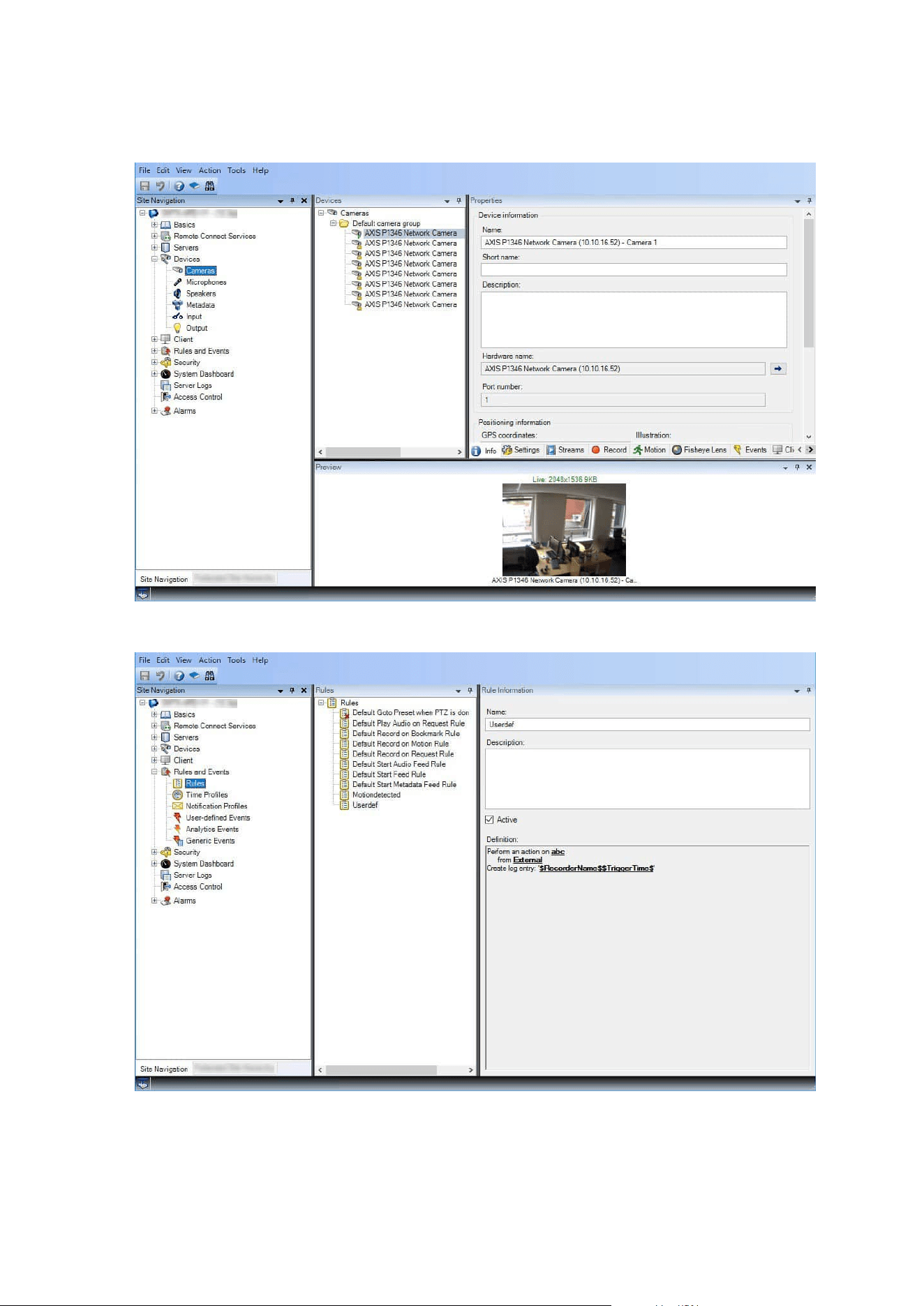
l
When you work with recording servers and devices:
l
When you work with rules, time and notification profiles, users, roles:
Administrator manual | XProtect® VMS 2023 R1
362 | User interface details
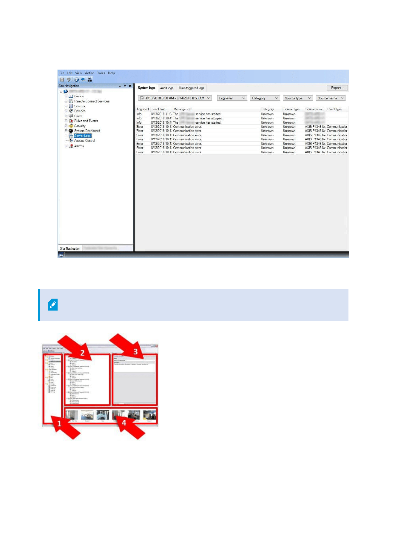
l
When you view logs:
Panes layout
The illustration outlines a typical window layout. You can customize the layout so it may
look different on your computer.
Administrator manual | XProtect® VMS 2023 R1
363 | User interface details

1. Site Navigation pane and Federated Site Hierarchy pane
2. Overview pane
3. Properties pane
4. Preview pane
Site Navigation pane
This is your main navigation element in the Management Client. It reflects the name, settings and
configurations of the site that you have logged into. The site name is visible at the top of the pane. The
features are grouped into categories that reflect the functionality of the software.
In the Site Navigation pane, you can configure and manage your system so it matches your needs. If your
system is not a single-site system, but includes federated sites, note that you manage these sites on the
Federated Site Hierarchy pane.
Available functionality depends on the system you are using. See the complete feature list, which is available
on the product overview page on the Milestone website
(https://www.milestonesys.com/solutions/platform/product-index/).
Federated Site Hierarchy pane
This is your navigation element that displays all Milestone Federated Architecture sites in a parent/child site
hierarchy.
You can select any site, log into it and the Management Client for that site launches. The site that you are
logged into, is always at the top of the hierarchy.
Overview pane
Provides an overview of the element you have selected in the Site Navigation pane, for example as a detailed
list. When you select an element in the Overview pane, it typically displays the properties in the Properties
pane. When you right-click elements in the Overview pane you get access to the management features.
Properties pane
Displays the properties of the element selected in the Overview pane. The properties appear on several
dedicated tabs:
Administrator manual | XProtect® VMS 2023 R1
364 | User interface details

Preview pane
The Preview pane appears when you work with recording servers and devices. It shows preview images from
the selected cameras or displays information about the state of the device. The example shows a camera
preview image with information about the resolution and data rate of the camera's live stream:
By default, the information shown with the camera preview images concerns live streams. This is displayed in
green text above the preview. If you want recording stream information instead (red text), select View > Show
Recording Streams in the menu.
Performance can be affected if the Preview pane displays preview images from many cameras at a high frame
rate. To control the number of preview images, and their frame rate, select Options > General in the menu.
System settings (Options dialog box)
In the Options dialog box, you can specify a number of settings related to the general appearance and
functionality of the system.
Available functionality depends on the system you are using. See the complete feature list, which is available
on the product overview page on the Milestone website
(https://www.milestonesys.com/solutions/platform/product-index/).
To access the dialog box, select Tools > Options.
Administrator manual | XProtect® VMS 2023 R1
365 | User interface details
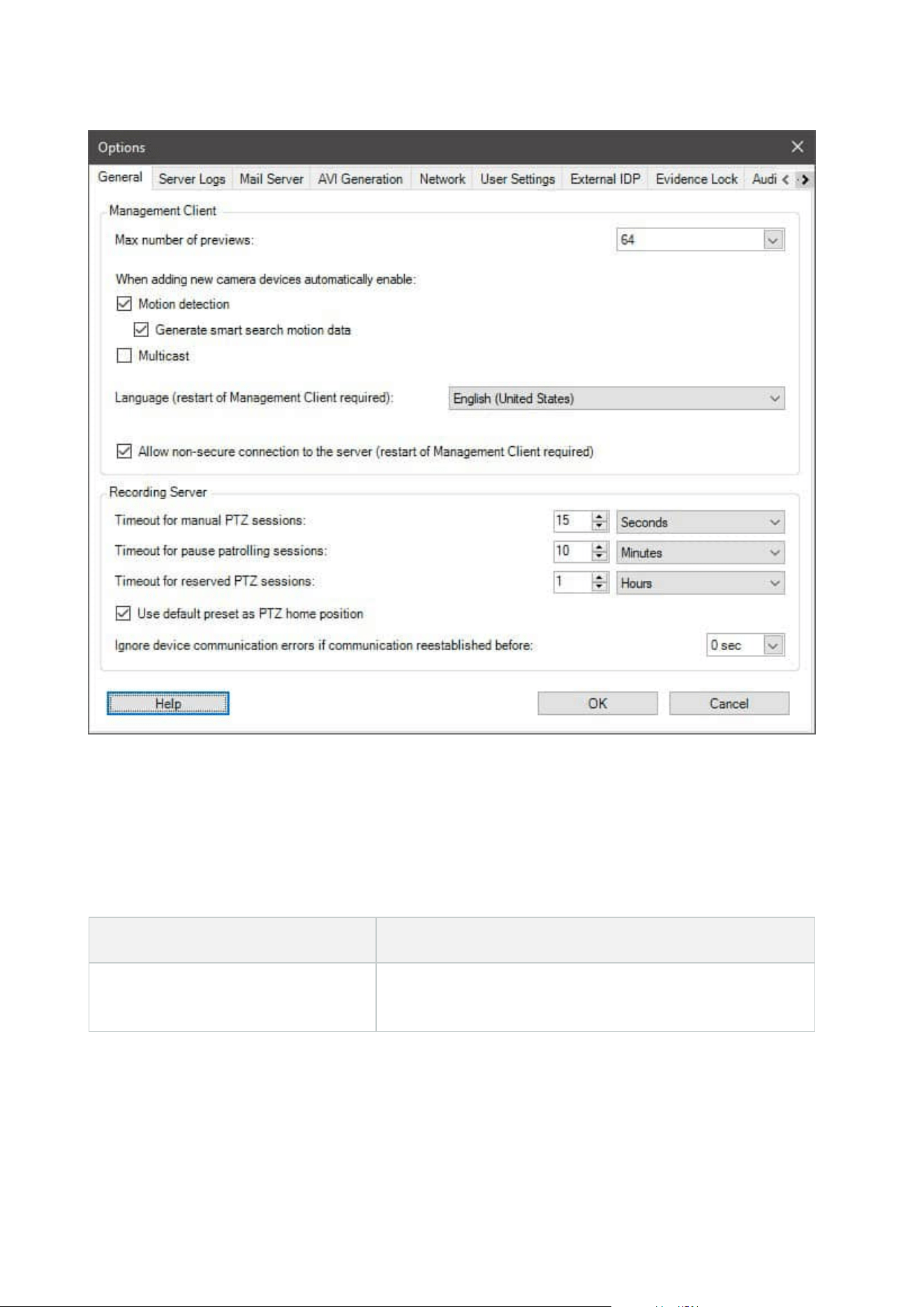
General tab (options)
On the General tab, you can specify general settings for the Management Client and the recording server.
Management Client
Name Description
Max number of previews
Select the maximum number of thumbnail images displayed in
the Preview pane. Default is 64 thumbnail images.
Administrator manual | XProtect® VMS 2023 R1
366 | User interface details

Name Description
Select Action > Refresh from the menu for the change to take
effect.
A large number of thumbnail images in combination with a
high frame rate may slow the system down.
When adding new camera devices
automatically enable: Motion
detection
Select the check box to enable motion detection on new
cameras, when you add them to the system with the Add
Hardware wizard.
This setting does not affect motion detection settings on
existing cameras.
You enable and disable motion detection for a camera on the
Motion tab for the camera device.
When adding new camera devices
automatically enable: Generate
motion data for smart search
Generation of motion data for smart search requires that
motion detection is enabled for the camera.
Select the check box to enable generation of smart search
motion data on new cameras, when you add them to the
system with the Add Hardware wizard.
This setting does not affect motion detection settings on
existing cameras.
You enable and disable the generation of smart search motion
data for a camera on the Motion tab for the camera device.
When adding new camera devices
automatically enable: Multicast
Select the check box to enable multicast on new cameras when
you add them with the Add Hardware wizard.
This setting does not affect multicast settings on existing
cameras.
You enable and disable live multicasting for a camera on the
Client tab for the camera device.
Language
Select the language of the Management Client.
Restart the Management Client to use the new language.
Allow non-secure connection to the
server
Select the check box to allow non-secure server connection by
HTTP protocol. (No users are prompted to allow non-secure
server connection).
Restart the Management Client to use this setting.
Administrator manual | XProtect® VMS 2023 R1
367 | User interface details

Recording server
Name Description
Timeout for manual
PTZ sessions
Client users with the necessary user permissions can manually interrupt the
patrolling of PTZ cameras. Select how much time should pass before regular
patrolling is resumed after a manual interruption. The setting applies for all PTZ
cameras on your system. Default setting is 15 seconds.
If you want individual timeouts on the cameras, you specify this on the Presets tab
for the camera.
Timeout for pause
patrolling sessions
Client users with a sufficient PTZ priority can pause patrolling on PTZ cameras.
Select how much time should pass before regular patrolling is resumed after a
pause. The setting applies for all PTZ cameras on your system. Default setting is 10
minutes.
If you want individual timeouts on the cameras, you specify this on the Presets tab
for the camera.
Timeout for
reserved PTZ
sessions
Set the default timeout period for reserved PTZ sessions. When a user runs a
reserved PTZ session, the PTZ camera cannot be used by others before it is
released either manually or when the period has timed out. Default setting is 1
hour.
If you want individual timeouts on the cameras, you specify this on the Presets tab
for the camera.
Use default preset
as PTZ home
position
Select this check box to use the default preset position instead of the home
position of PTZ cameras when activating the Home button in a client.
A default preset position must be defined for the camera. If a default preset
position is not defined, nothing will happen when activating the Home button in a
client.
By default, this check box is cleared.
To assign a default preset position, see Assign a camera's preset position as
default on page 233
Ignore device
communication
The system logs all communication errors on hardware and devices, but here you
select for how long a communication error must exist before the rule engine
Administrator manual | XProtect® VMS 2023 R1
368 | User interface details

Name Description
errors if
communication
reestablished
before
triggers the Communication Error event.
Server Logs tab (options)
On the Server Logs tab, you can specify settings for the system’s management server logs.
For more information, see Identify user activity, events, actions and errors.
Name Description
Logs
Select the log type that you want to configure:
l
System logs
l
Audit logs
l
Rule-triggered logs
Settings
Disable or enable the logs and specify the retention period.
Allow 2018 R2 and earlier components to write logs. For more information, see Allow 2018
R2 and earlier components to write logs.
For System logs, specify the level of messages that you want to log:
l
All (includes undefined messages)
l
Information, warnings, and errors
l
Warnings and errors
l
Errors (default setting)
For Audit logs, enable user access logging if you want the system to log all user actions in
XProtect Smart Client. These are, for example, exports, activating outputs, and viewing
cameras live or in playback.
Specify:
Administrator manual | XProtect® VMS 2023 R1
369 | User interface details

Name Description
l
The length of a playback sequence
This means that as long as the user plays back within this period, the system only
generates one log entry. When playing back outside the period, the system creates
a new log entry.
l
The number of records (frames) a user has seen before the system creates a log
entry
Mail Server tab (options)
On the Mail Server tab, you can specify the settings for your system's mail server.
For more information, see Notification profiles (explained).
Name Description
Sender e-mail
address
Enter the email address that you want to appear as the sender of email notifications for
Mail server
address
Enter the address of the SMTP mail server that sends e-mail notifications. Example:
mailserver.organization.org.
Mail server
port
The TCP port used for connecting to the mail server. Default port is 25 for unencrypted
connections, Encrypted connections typically use port 465 or 587.
Encrypt the
connection to
the server
If you want to secure the communication between the management server and the
SMTP mail server, select this check box.
The connection is secured using the STARTTLS email protocol command. In this mode,
the session begins on an unencrypted connectcion, then a STARTTLS command is issued
by the SMTP mail server to the management server to switch to secure communication
using SSL.
Server
requires login
If enabled, you must specify a user name and password for the users to log in to the
mail server.
Administrator manual | XProtect® VMS 2023 R1
370 | User interface details

AVI Generation tab (options)
On the AVI Generation tab, you can specify compression settings for the generation of AVI video clip files. The
settings are required if you want to include AVI files in e-mail notifications sent by rule-triggered notification
profiles.
See also Trigger email notifications from rules.
Name Description
Compressor
Select the codec (compression/decompression technology) that you want to
apply. To have more codecs available in the list, install them on the
management server.
Not all cameras support all codecs.
Compressionquality
(Not available for all codecs). Use the slider to select the degree of
compression (0-100) to be performed by the codec.
0 means no compression, generally resulting in high image quality and large
file size. 100 means maximum compression, generally resulting in low image
quality and small file size.
If the slider is not available, the compression quality is determined entirely by
the selected codec.
Keyframe every
(Not available for all codecs). If you want to use keyframes, select the check
box and specify the required number of frames between keyframes.
A keyframe is a single frame stored at specified intervals. The keyframe
contains the entire view of the camera, whereas the following frames contain
only the pixels that change. This helps greatly reduce the size of files.
If the check box is not available, or not selected, every frame contains the
entire view of the camera.
Data rate
(Not available for all codecs). If you want to use a particular data rate, select
the check box and specify the number of kilobytes per second.
The data rate specifies the size of the attached AVI file.
If the check box is not available, or not selected, the data rate is determined
by the selected codec.
Administrator manual | XProtect® VMS 2023 R1
371 | User interface details
Network tab (options)
On the Network tab, you can specify the IP addresses of the local clients, if the clients are to connect to the
recording server via the Internet. The surveillance system then recognizes them as coming from the local
network.
You can also specify the IP version of the system: IPv4 or IPv6. Default value is IPv4.
Bookmark tab (options)
Available functionality depends on the system you are using. See the complete feature
list, which is available on the product overview page on the Milestone website
(https://www.milestonesys.com/solutions/platform/product-index/).
On the Bookmarks tab, you can specify settings for bookmarks, their IDs and function in XProtect Smart Client.
Name Description
Bookmark ID prefix
Specify a prefix for all the bookmarks that is made by the users of XProtect Smart
Client.
Default bookmark
time
Specify the default start and end time of a bookmark is set in XProtect Smart
Client.
This setting needs to be aligned with:
l
The default bookmark rule, see Rules (Rules and Events node).
l
The pre-buffer period for each camera, see Manage pre-buffering.
To specify the bookmark permissions of a role, see Device tab (roles) on page 523.
User Settings tab (options)
On the User Settings tab, you can specify user preference settings, for example, if a message should be shown
when remote recording is enabled.
External IDP tab (options)
On the External IDP tab in Management Client, you can add and configure an external IDP and register claims
from the external IDP.
Administrator manual | XProtect® VMS 2023 R1
372 | User interface details
Name Description
Enabled The external IDP is by default enabled.
Name
The name for the external IDP. The name that you enter here appears in the
Authentication field in the log in window of your client.
Authentication
authority
The URL of the external IDP.
Add
Add and configure an external IDP. When you select Add, the External IDP dialog
box opens and you can enter the information for the configuration, see Configure
an external IDP below the table.
Edit Edit the configuration of the external IDP.
Remove
Remove the external IDP configuration.
If you remove an external IDP configuration, the users that
are authenticated via this external IDP will not be able to log
in to the XProtect VMS. If you add the external IDP again, new
users will be created on log in because the ID of the external
IDP has changed.
Configure an external IDP
l
To add an external IDP, select Add in the External IDP section and enter the information in the table
below:
Name Description
Name
The name for the external IDP that you enter here appears in the Authentication field in
the log in window of your client.
Client ID
and Client
secret
Must be obtained from the external IDP. The client ID and the client secret are needed to
communicate securely with the external IDP.
Administrator manual | XProtect® VMS 2023 R1
373 | User interface details

Name Description
Callback
path
Part of a URL for the authentication redirect flow to sign in users.
Users are signed in from a sign-in page that is hosted by the external IDP. When the
authentication process is completed, this path is invoked and the user is redirected to the
XProtect VMS.
The default value is “/signin-oidc”.
The redirect format
The URI of the callback path is constructed by the management server FQID together with
/idp/ and the callback path configured on the external provider.
Examples:
l
Redirect URI format for the XProtect Smart Client and the XProtect Management
Client: [schema]://[management server address]/idp/[callback path]
l
Redirect URI format for the XProtect Web Client and XProtect Mobile client: [redirect
Uri without “/index.html”]/idp/[callback path]
Note, that the "idp" part of the callback path is case sensitive and it must be entered in
lowercase letters.
Prompt for
login
Specify to the external IDP if the user should stay logged in or if a verification of the user is
required. Depending on the external IDP, the verification can include a password
verification or a full log-in.
Claim to
use to
create user
name
Optionally, specify which claim from the external IDP that should be used to generate a
unique user name for the auto-provisioned user in the VMS. For more information about
unique user names crated by claims, see Unique user names for external IDP users.
Scopes
Optionally, use scopes to limit the number of claims that you get from an external IDP. If
you know that the claims that are relevant for your VMS are in a specific scope, you can use
the scope to limit the number of claims that you get from the external IDP.
Register claims
When you have registered claims from the external IDP, you can map the claims to roles in the VMS to
determine the user privileges in the VMS. For more information, see Map claims from an external IDP.
l
To register claims from an external IDP, select Add in the Registered claims section and enter the
information in the table below:
Administrator manual | XProtect® VMS 2023 R1
374 | User interface details
Name Description
External
IDP
The name of the external IDP.
Claim name Name of the claim in free text. The name will be available when selecting a role.
Display
name
The display name of a claim.
Case
sensitive
Indicates whether the value of a claim is case sensitive.
Examples of values that are typically case sensitive:
- Textual representations of IDs such as a guid: F951B1F0-2FED-48F7-88D3-49EB5999C923
or OadFgrDesdFesff=
Examples of values that are typically not case sensitive:
- E-mail addresses
- Role names
- Group names
.
Add, Edit,
Remove
Register and maintain claims.
If you modify a claim at the external IDP web site, a new log in to
the XProtect client is required by the users. Say, that a user, Bob,
needs to be, for example, Operator. The claim is then added to Bob
at the external IDP web site, but if Bob is already logged in to
XProtect, he must complete a new login for the change to take
effect.
Add redirect URIs for the web clients
The redirect URI is the location where the user is redirected after a successful log in. The redirect URIs must be
an exact match of the addresses of the web clients. For example, you will not be able to log in via an external
IDP if you open XProtect Web Client from https://localhost:8082/index.html and the redirect URI for the web
clients you added is https://127.0.0.1:8082/index.html.
Administrator manual | XProtect® VMS 2023 R1
375 | User interface details
Name Description
URI
The URIof XProtect Web Client in the format https://[mobile server]:[port]/index.html.
The redirect URIs are not case sensitive.
Add, Edit,
Remove
Register and maintain redirect URIs.
When you remove URIs, you must keep at least one redirect URI for
the system to work.
Customer Dashboard tab (options)
On the Customer Dashboard tab, you can enable or disable Milestone Customer Dashboard.
Customer Dashboard is an online monitoring service that provides a graphical overview of the current status
of your system, including possible technical issues such as camera failures, to system administrators or other
people that have been given access to information about your system installation.
You can select or clear the check box to change your Customer Dashboard settings at any time.
Evidence Lock tab (options)
Available functionality depends on the system you are using. See the complete feature
list, which is available on the product overview page on the Milestone website
(https://www.milestonesys.com/solutions/platform/product-index/).
On the Evidence Lock tab, you define and edit evidence lock profiles and the duration your client users can
select to keep the data protected.
Name Description
Evidence
lock profiles
A list with defined evidence lock profiles.
You can add and remove existing evidence lock profiles. You cannot remove the default
evidence lock profile, but you can change its time options and its name.
Lock time
options
The duration the client users can select to lock evidence.
Available time options are hour(s), day(s), week(s), month(s), year(s), indefinite or user-
defined.
Administrator manual | XProtect® VMS 2023 R1
376 | User interface details

To specify the evidence lock access permissions of a role, see the Device tab (roles) on page 523 for role
settings.
Audio messages tab (options)
On the Audio messages tab, you can upload files with audio messages that are used for broadcasting
messages, triggered by rules.
The maximum number of uploaded files is 50 and the maximum size allowed for each file is 1 MB.
Name Description
Name
Provides the name of a message. You enter the name when you add a message. To
upload a message to the system, click Add.
Description
Provides a description of the message.
You enter the description when you add a message. You can use the description field to
describe the purpose or the actual message.
Add
Lets you upload audio messages to the system.
Supported formats are standard Windows audio file formats:
l
.wav
l
.wma
l
.flac
Edit Lets you modify the name and description, or you can replace the actual file.
Remove Delete the audio message from the list.
Play
Click this button to listen to the audio message from the computer that runs the
Management Client.
To create a rule that triggers playback of audio messages, see Add a rule.
To learn more about actions in general that you can use in rules, see Actions and stop actions.
Administrator manual | XProtect® VMS 2023 R1
377 | User interface details
Privacy settings tab
On the Privacy settings tab, you can enable or disable usage data collection in XProtect Mobile Server,
XProtect Mobile client, XProtect Web Client and XProtect Smart Client. Then, click OK.
By enabling usage data collection, you consent to Milestone Systems's use of technology
by Google as a third-party provider, with which data processing in the USA cannot be
excluded. For more information about data protection and the usage data collection, see
the GDPRprivacy guide.
Access Control Settings tab (options)
The use of XProtect Access requires that you have purchased a base license that allows
you to access this feature.
Name Description
Show development
property panel
If selected, additional developer information appears for Access Control >
General Settings.
This setting is only meant to be used by developers of access control
system integrations.
Analytics Events tab (options)
On the Analytics Events tab, you can enable and specify the analytics events feature.
Name Description
Enable Specify if you want to use analytics events. As default, the feature is disabled.
Port
Specify the port used by this feature. The default port is 9090.
Make sure that relevant VCA tool providers also use this port number. If you change
Administrator manual | XProtect® VMS 2023 R1
378 | User interface details
Name Description
the port number, remember to change the port number of the providers.
All network
addresses or
Specified network
addresses
Specify if events from all IP addresses/hostnames are allowed, or only events from
IP addresses/hostnames that are specified in the Address list (see below).
Address list
Specify a list of trusted IP addresses/hostnames. The list filters incoming data so
that only events from certain IP addresses/hostnames are allowed. You can use
both Domain Name System (DNS), IPv4 and IPv6 address formats.
You can add addresses to your list by manually entering each IP address or host
name, or by importing an external list of addresses.
l
Manual entering: Enter the IP address/hostname in the address list. Repeat
for each required address
l
Import: Click Import to browse for the external list of addresses. The
external list must be a .txt file and each IP address or host name must be on
a separate line
Alarms and Events tab (options)
On the Alarms and Events tab, you can specify settings for alarms, events and logs. Related to these settings,
see also Limit size of database on page 123.
Name Description
Keep closed alarms
for
Specify the number of days for storing alarms with the state Closed in the
database. If you set the value to 0, the alarm is deleted after it has been closed.
Administrator manual | XProtect® VMS 2023 R1
379 | User interface details
Name Description
Alarms always have timestamps. If the alarm is triggered by
a camera, the timestamp has an image from the time of the
alarm. The alarm information itself is stored on the event
server, while the video recordings corresponding to the
attached image are stored on the relevant surveillance
system server.
To be able to see the images of your alarms, keep video
recordings for at least as long as you intend to keep alarms
on the event server.
Keep all other
alarms for
Specify the number of days for storing alarms with the state New, In progress, or
On hold. If you set the value to 0, the alarm appears in the system, but will not be
stored.
Alarms always have timestamps. If the alarm is triggered by
a camera, the timestamp has an image from the time of the
alarm. The alarm information itself is stored on the event
server, while the video recordings corresponding to the
attached image are stored on the relevant surveillance
system server.
To be able to see the images of your alarms, keep video
recordings for at least as long as you intend to keep alarms
on the event server.
Keep logs for
Specify the number of days for keeping the event server logs. If you keep the logs
for longer periods of time, ensure that the machine where the event server is
installed has enough disk space.
Enable verbose
logging
To keep a more detailed log for event server communication, select the check box.
It will be stored for the number of days specified in the Keep logs for field.
Event types
Specify the number of days for storing events in the database. There are two ways
of doing this:
Administrator manual | XProtect® VMS 2023 R1
380 | User interface details
Name Description
l
You can specify the retention time for an entire event group. Event types
with the value Follow group will inherit the value of the event group
l
Even if you set a value for an event group, you can specify the retention
time for individual event types.
If the value is 0, the events will not be stored in the
database.
The external events (user-defined events, generic events,
and input events) are set to 0 by default, and you cannot
change that value. The reason is that these types of events
occur so frequently that storing them in the database may
cause performance issues.
Generic Events tab (options)
On the Generic Events tab, you can specify generic events and data source related settings.
For more information about how to configure actual generic events, see Generic events (explained).
Name Description
Data source
You can choose between two default data sources and define a custom data source.
What to choose depends on your third party program and/or the hard- or software you
want to interface from:
Compatible: Factory default settings are enabled, echoes all bytes, TCP and UDP, IPv4
only, port 1234, no separator, local host only, current code page encoding (ANSI).
International: Factory default settings are enabled, echoes statistics only, TCP only,
IPv4+6, port 1235, <CR><LF> as separator, local host only, UTF-8 encoding. (<CR><LF> =
13,10).
[Data source A]
Administrator manual | XProtect® VMS 2023 R1
381 | User interface details

Name Description
[Data source B]
and so on.
New Click to define a new data source.
Name Name of the data source.
Enabled Data sources are by default enabled. Clear the check box to disable the data source.
Reset
Click to reset all settings for the selected data source. The entered name in the Name
field remains.
Port The port number of the data source.
Protocol type
selector
Protocols which the system should listen for, and analyze, in order to detect generic
events:
Any: TCP as well as UDP.
TCP: TCP only.
UDP: UDP only.
TCP and UDP packages used for generic events may contain special characters, such as
@, #, +, ~, and more.
IP type
selector
Selectable IP address types: IPv4, IPv6 or both.
Separator
bytes
Select the separator bytes used to separate individual generic event records. Default for
data source type International (see Data sources earlier) is 13,10. (13,10 = <CR><IF>).
Echo type
selector
Available echo return formats:
l
Echo statistics: Echoes the following format: [X],[Y],[Z],[Name of generic event]
[X] = request number.
[Y] = number of characters.
[Z] = number of matches with a generic event.
[Name of generic event] = name entered in the Name field.
Administrator manual | XProtect® VMS 2023 R1
382 | User interface details
Name Description
l
Echo all bytes: Echoes all bytes
l
No echo: Suppresses all echoing
Encoding
type selector
By default, the list only shows the most relevant options. Select the Show all check box to
display all available encodings.
Allowed
external IPv4
addresses
Specify the IP addresses, that the management server must be able to communicate with
in order to manage external events. You can also use this to exclude IP addresses that
you do not want data from.
Allowed
external IPv6
addresses
Specify the IP addresses, that the management server must be able to communicate with
in order to manage external events. You can also use this to exclude IP addresses that
you do not want data from.
Component menus
Management Client menus
File menu
You can save changes to the configuration and exit the application. You can also back up your configuration,
see Backing up and restoring your system configuration (explained) on page 313.
Edit menu
You can undo changes.
View menu
Name Description
Reset Application
Layout
Reset the layout of the different panes in the Management Client to their default
settings.
Administrator manual | XProtect® VMS 2023 R1
383 | User interface details
Name Description
Preview Window
Toggle the Preview pane on and off when working with recording servers and
devices.
Show Recording
Streams
By default, the information shown with preview images in the Preview pane
concerns live streams of the cameras. If you want information about recording
streams instead, select Show Recording Streams.
Federated Site
Hierarchy
By default, the Federated Site Hierarchy pane is enabled.
Site Navigation By default, the Site Navigation pane is enabled.
Action menu
The content of the Action menu differs depending on the element you have selected in the Site Navigation
pane. The actions you can choose from are the same as when you right-click the element.
The pre-buffer period for each camera, see Manage pre-buffering.
Name Description
Refresh Is always available and reloads the requested information from the management server.
Tools menu
Name Description
RegisteredServices
Manage registered services.
See Managing registered services on page 340.
EffectiveRoles View all roles of a selected user or group.
Options
Opens the Options dialog box, which lets you define and edit global system
settings. For more information see System settings (Options dialog box) on
page 365.
Administrator manual | XProtect® VMS 2023 R1
384 | User interface details

Help menu
You can access the help system and information about the version of the Management Client.
Server Configurator (Utility)
Encryption tab properties
This tab allows you to specify the following properties:
In a cluster environment, you must set up your cluster and ensure that it is running
before you create certificates for all the computers in the cluster environment. After that
you can install the certificates and do the registration using the Server Configurator for
all the nodes in the cluster. For more information, see the certificates guide about how
to secure your XProtect VMS installations.
Name Description Task
Server
certificate
Select the certificate to be used to encrypt
the two-way connection between the
management server, data collectors, and
recording servers.
Enable encryption to and from the
management server
Enable server encryption for recording
servers or remote servers
Event server
and add-ons
Select the certificate to be used to encrypt
the two-way connection between the event
server and the components that
communicate with the event server,
including the LPR Server.
Enable event server encryption on page
288
Streaming
media
certificate
Select the certificate to be used to encrypt
communication between the recording
servers and all clients, servers, and
integrations that retrieve data streams
from the recording servers.
Enable encryption to clients and servers
Mobile
streaming
media
certificate
Select the certificate to be used to encrypt
communication between the mobile server
and the mobile and web clients that
retrieve data streams from the mobile
server.
Enable encryption on the mobile server
Administrator manual | XProtect® VMS 2023 R1
385 | User interface details
Registering servers
Name Description Task
Management
server address
The address of the management server typically
includes the hostname or the fully qualified
domain name (FQDN) of the computer.
By default, this address is only active from a
computer in the XProtect VMS where the
management server is not installed.
As a rule of thumb, the management server
address should not be changed from a computer
that has the management server installed.
However, if, for example, you use the Server
Configurator in a failover setup, you might have
to change the address from the management
server computer. This could be within a cluster
failover environment or in another failover setup
scenario.
l
To activate the Management server
address field from a computer with the
management server installed, click the
pen (
) symbol.
If you update the
management server
address, you need to
access each of the
computers that have
components installed and
update the management
server address with the
new address information.
Click for more information
about the implications of
changing the management
server address from a computer
that has the management
server installed:
Changing the host name of the
management server computer
Register
Register the servers that are running on the
computer with the designated management
server.
Register a recording server
Administrator manual | XProtect® VMS 2023 R1
386 | User interface details
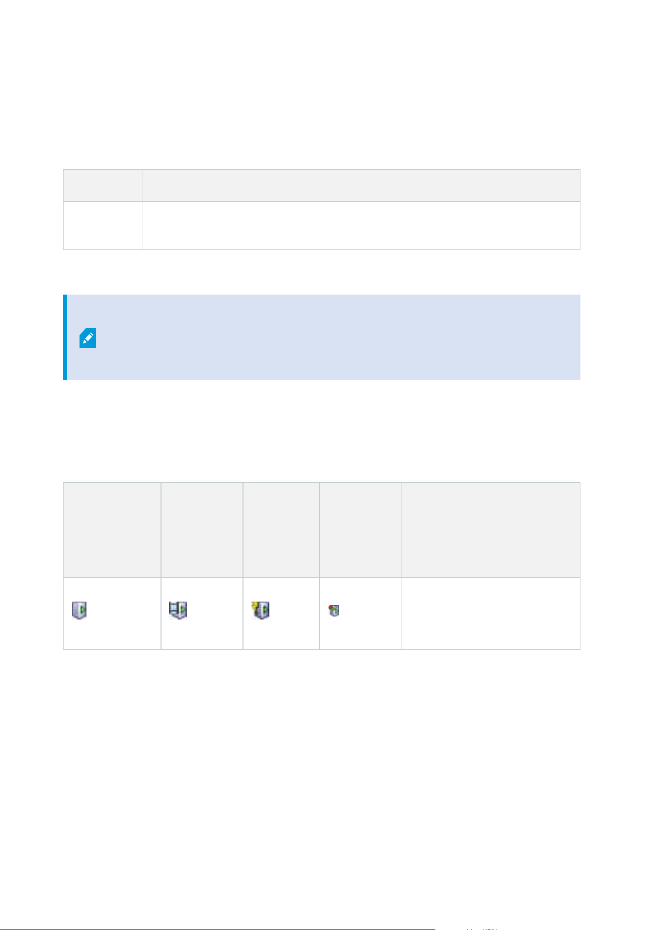
Language selection
Use this tab to select the language for the Server Configurator. The set of languages for the Server
Configurator corresponds to the set of languages for the Management Client.
Name Description
Choose
language
Choose the language of the user interface.
If you work in a failover cluster environment, it is recommended that you pause the
cluster before you start tasks in the Server Configurator. This is because the Server
Configurator may need to stop services while applying changes and the failover cluster
environment may interfere with this operation.
Tray icon status
The tray icons in the table show the different states of the services running on the servers in the XProtect VMS.
The icons are available on computers with the servers installed:
Management
Server Manager
tray icon
Recording
Server
Managertray
icon
Event
Server
Manager
tray icon
Failover
Recording
Server
Manager
tray icon
Description
Running
Appears when a server service is
enabled and started.
Administrator manual | XProtect® VMS 2023 R1
387 | User interface details
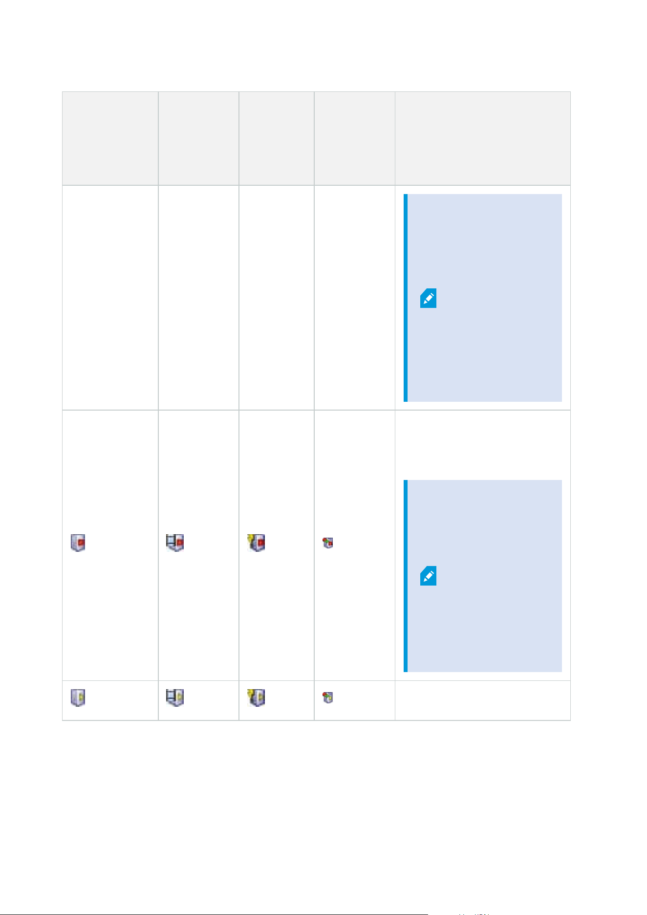
Management
Server Manager
tray icon
Recording
Server
Managertray
icon
Event
Server
Manager
tray icon
Failover
Recording
Server
Manager
tray icon
Description
If the
Failover
Recording
Server
service is
running, it
can take
over if the
standard
recording
servers
fails.
Stopped
Appears when a server service has
stopped.
If the
Failover
Recording
Server
service
stops, it
cannot take
over if the
standard
recording
server fails.
Starting
Administrator manual | XProtect® VMS 2023 R1
388 | User interface details
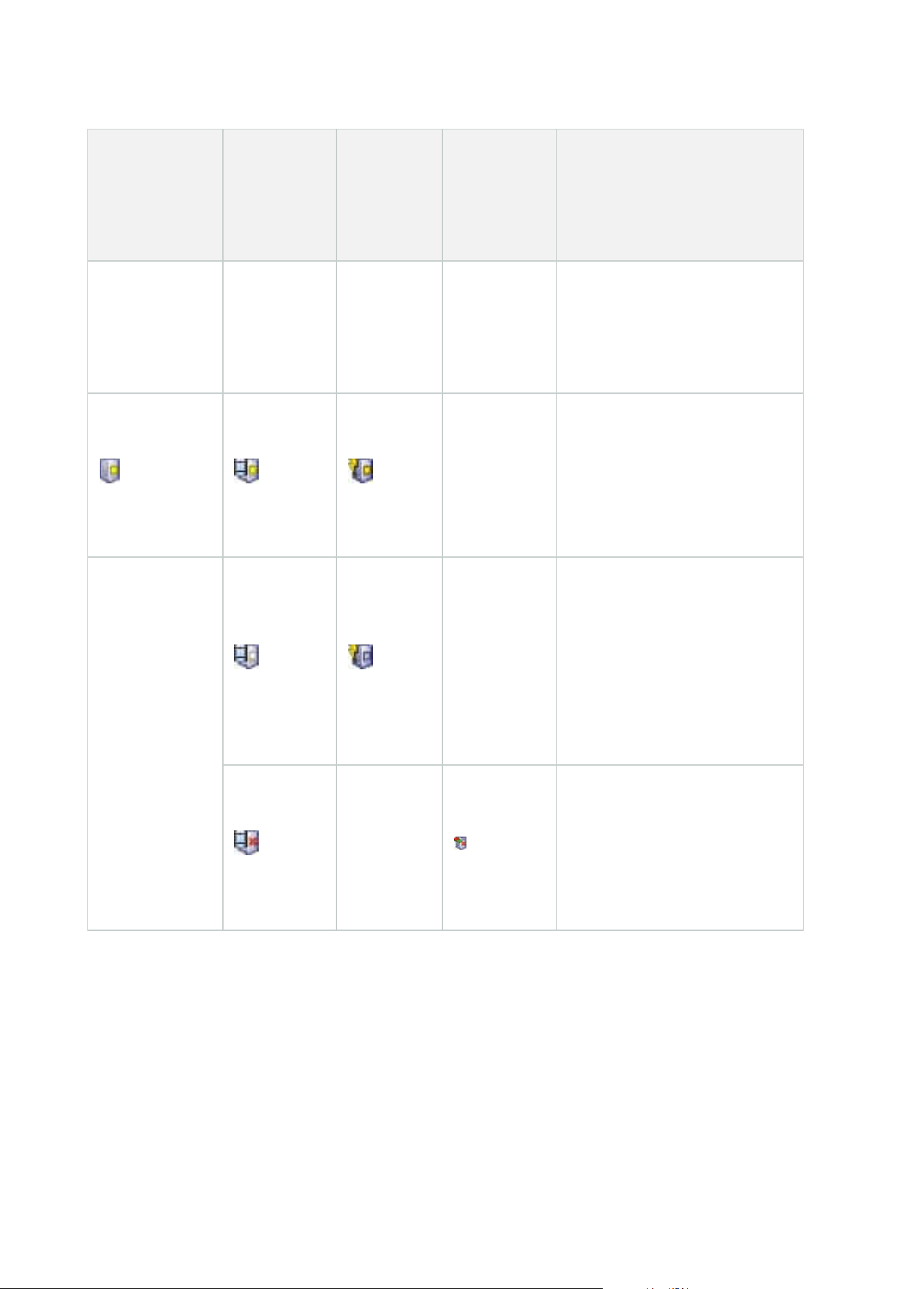
Management
Server Manager
tray icon
Recording
Server
Managertray
icon
Event
Server
Manager
tray icon
Failover
Recording
Server
Manager
tray icon
Description
Appears when a server service is
in the process of starting. Under
normal circumstances, the tray
icon changes after a short while to
Running.
Stopping
Appears when a server service is
in the process of stopping. Under
normal circumstances, the tray
icon changes after a short while to
Stopped.
In indeterminate state
Appears when the server service
is initially loaded and until the first
information is received, upon
which the tray icon, under normal
circumstances, changes to
Starting and afterwards to
Running.
Running offline
Typically appears when the
Recording Server or Failover
recording service is running but
the Management Server service is
not.
Starting and stopping services from tray icons
Right-click the icons in the notification area to open the tray icons where you can start and stop services.
Administrator manual | XProtect® VMS 2023 R1
389 | User interface details

l
Start or stop the Management Server service
l
Start or stop the Recording Server service
Management Server Manager (tray icon)
Use the menu items on the Management Server Manager tray icon to perform tasks from the Management
Server Manager.
Name Description
Start Management
Server and Stop
Management Server
Click the appropriate menu item to start or to stop the Management Server
service. If you stop the Management Server service, you cannot use the
Management Client.
The state of the service is reflected by the tray icon. For more information about
the states of the tray icons, see Server manager tray icons (explained).
Show status
messages
View a list of time-stamped status messages.
Change system
configuration
password settings
Assign or change a system configuration password. You can also choose not to
password protect the system configuration by removing any assigned system
configuration passwords.
Change the system configuration password settings
Enter the system
configuration
password
Enter a password. This applies if, for example, the file that is holding the
password settings is deleted or corrupted. For more information, see Enter the
system configuration password settings.
Configure failover
management server
Launch the configuration wizard for the failover management server or open
the Manage your configuration page to manage your existing configuration.
For more information about the failover cluster, see XProtect Management
Server Failover on page 36.
Server Configurator
Open the Server Configurator to register servers and manage encryption. For
more information about managing encryption, see Manage encryption with the
Server Configurator.
Change license
On the management server computer, change the software license code. You
would need to enter a new license code to, for example, upgrade your XProtect
Administrator manual | XProtect® VMS 2023 R1
390 | User interface details

Name Description
system. For more information, see Change the Software License Code.
Restore configuration
Open a dialog box from where you can restore the system configuration. Make
sure, you read the information in the dialog box, before you click Restore. For
more information, see Restore system configuration from a manual backup.
Select shared backup
folder
Set a backup folder to store your backup in, before you back up any system
configuration. For more information, see Select shared backup folder.
Update SQL address
Open a wizard to change the address of the SQL Server. In the rare event of a
host name change, the SQL Server address might need to be aligned with the
changes. For more information, see A host name change can trigger the change
of the SQL server address.
Basics node
License Information (Basics node)
In the License Information window, you can keep track of all licenses that share the same software license file
both on this site and on all other sites, your Milestone Care subscriptions and decide how you want to activate
your licenses.
To learn more about the various information and features available from the License Information window, see
License Information window on page 118.
Site Information (Basics node)
In a large Milestone Federated Architecture setup with a lot of child sites, it is easy to lose the overview and it
can be difficult to find the contact information to the administrators of each child site.
Therefore, you can add additional information to each child site and this information is then available for the
administrators on the central site.
It is possible to add the following information:
l
Site name
l
Address/location
l
Administrator(s)
l
Additional information
Administrator manual | XProtect® VMS 2023 R1
391 | User interface details

Remote Connect Services node
Axis One-click Camera Connection (Remote Connect Services node)
These are the Axis One-Click Camera connection properties.
Name Description
Camera password
Enter/edit. Provided with your camera at purchase. For further details, see
your camera's manual or go to the Axis website (https://www.axis.com/).
Camera user See details for Camera password.
Description Enter/edit a description for the camera.
External address Enter/edit the web address of the ST server to which the camera(s) connect.
Internal address
Enter/edit the web address of the ST server to which the recording server
connects.
Name If needed, edit the name of the item.
Owner authentication
key
See Camera password.
Passwords (for Dispatch
Server)
Enter password. Must be identical to the one received from your system
provider.
Passwords (for ST
server)
Enter password. Must be identical to the one entered when the Axis One-Click
Connection Component was installed.
Register/Unregister at
the Axis Dispatch
Service
Indicate whether you wish to register your Axis camera with the Axis dispatch
service. Can be done at time of setup or later.
Serial number
Hardware serial number as specified by the manufacturer. The serial number
is often, but not always, identical to the MAC address.
Use credentials
Select the check box if you decided to use credentials during the installation
Administrator manual | XProtect® VMS 2023 R1
392 | User interface details
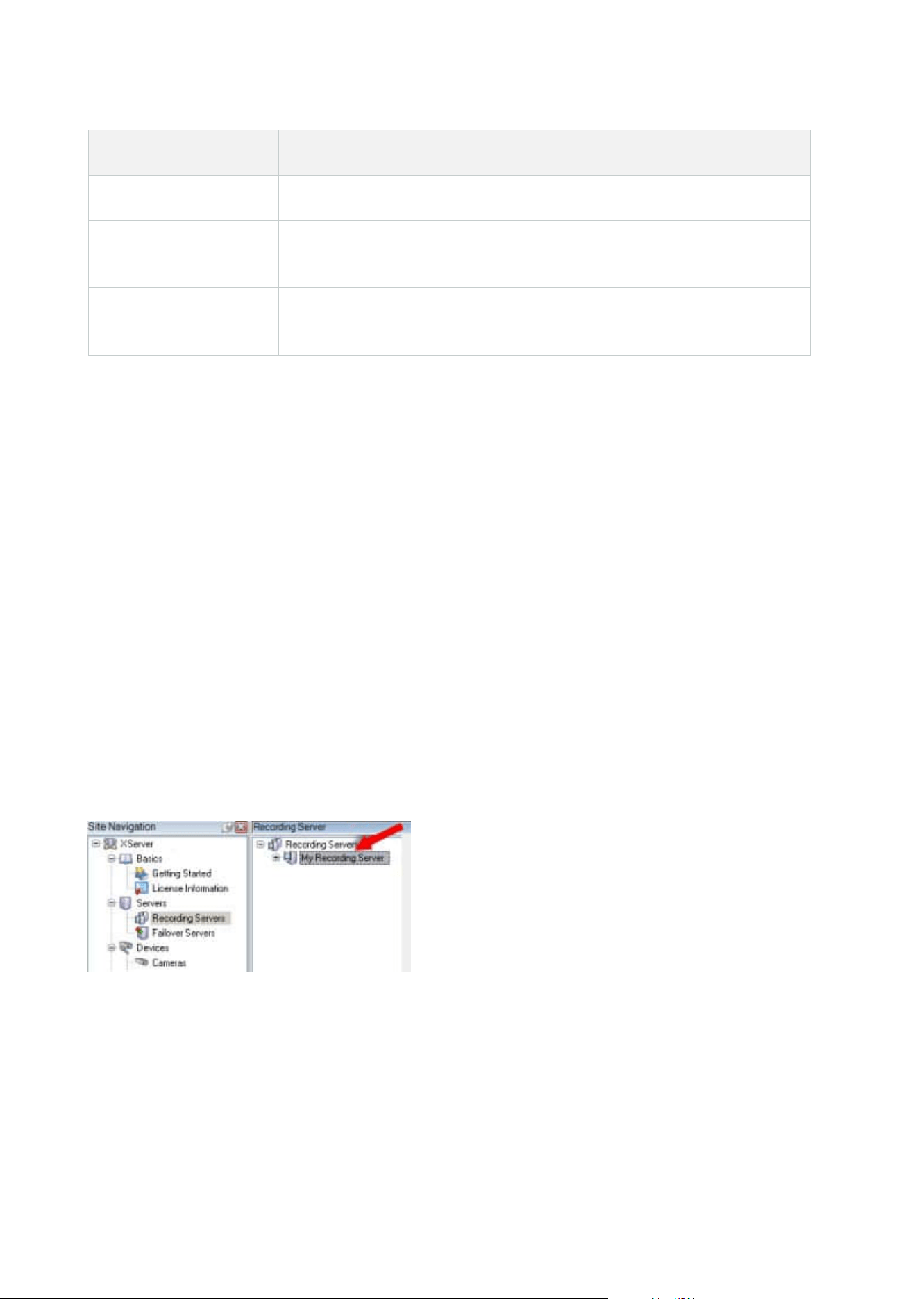
Name Description
of the ST server.
User name (for Dispatch
Server)
Enter a user name. The user name must be identical to the one received from
your system provider.
User name (for ST
server)
Enter user name. Must be identical to the one entered when the Axis One-
Click Connection Component was installed.
Servers node
Servers (node)
This section describes how to install and configure recording servers and failover recording servers. You also
learn how to add new hardware to the system and interconnect other sites.
l
Recording Servers (Servers node) on page 393
l
Failover Servers (Servers node) on page 406
Recording Servers (Servers node)
The system uses recording servers for recording of video feeds, and for communicating with cameras and
other devices. A surveillance system typically consists of several recording servers.
Recording servers are computers where you have installed the Recording Server software, and configured it to
communicate with the management server. You can see your recording servers in the Overview pane when
you expand the Servers folder and then select Recording Servers.
Backward compatibility with recording server versions older than this version of the management server is
limited. You can still access recordings on recording servers with older versions, but if you want to change their
configuration, make sure they match this version of the management server. Milestone recommends that you
upgrade all recording servers in your system to the same version as your management server.
Administrator manual | XProtect® VMS 2023 R1
393 | User interface details

Recording Server Settings window
When you right-click the Recording Server Manager tray icon and select Change settings, you can specify the
following:
Name Description
Address
IP address (example: 123.123.123.123) or host name (example: ourserver) of the
management server to which the recording server should be connected. This
information is necessary so that the recording server can communicate with the
management server.
Port
Port number to be used when communicating with the management server. Default
is port 9000. You can change this if you need to.
Web server port
Port number to be used for handling web server requests, for example for handling
PTZ camera control commands and for browse and live requests from XProtect Smart
Client. Default is port 7563. You can change this if you need to.
Alert server port
Port number to be used when the recording server listens for TCP information (some
devices use TCP for sending event messages). Default is port 5432 (disabled by
default). You can change this if you need to.
SMTP server
port
Port number to be used when the recording server listens for Simple Mail Transfer
Protocol (SMTP) information. SMTP is a standard for sending email messages
between servers. Some devices use SMTP for sending event messages or images to
the surveillance system server via email. Default is port 25, which you can enable and
disable. You can change the port number if you need to.
Encrypt
connections
from the
management
server to the
recording server
Before you enable encryption and select a server authentication certificate from the
list, make sure that you enable encryption on the management server first and that
the management server certificate is trusted on the recording server.
For more information, see Secure communication (explained) on page 138.
Encrypt
connections to
clients and
services that
Before you enable encryption and select a server authentication certificate from the
list, make sure that the certificate is trusted on all computers running services that
retrieve data streams from the recording server.
Administrator manual | XProtect® VMS 2023 R1
394 | User interface details

Name Description
stream data
XProtect Smart Client and all services that retrieve data streams from the recording
server must be upgraded to version 2019 R1 or later. Some third-party solutions
created using MIP SDK versions older than 2019 R1 may need to be updated.
For more information, see Secure communication (explained) on page 138.
To verify that your recording server uses encryption, see View encryption status to
clients on page 276.
Details View Windows Certificate Store information about the selected certificate.
Recording servers properties
Info tab (recording server)
On the Info tab, you can verify or edit the name and description of the recording server.
You can view the host name and addresses. The padlock icon in front of the web server address indicates
encrypted communication with the clients and services that retrieve data streams from this recording server.
Administrator manual | XProtect® VMS 2023 R1
395 | User interface details
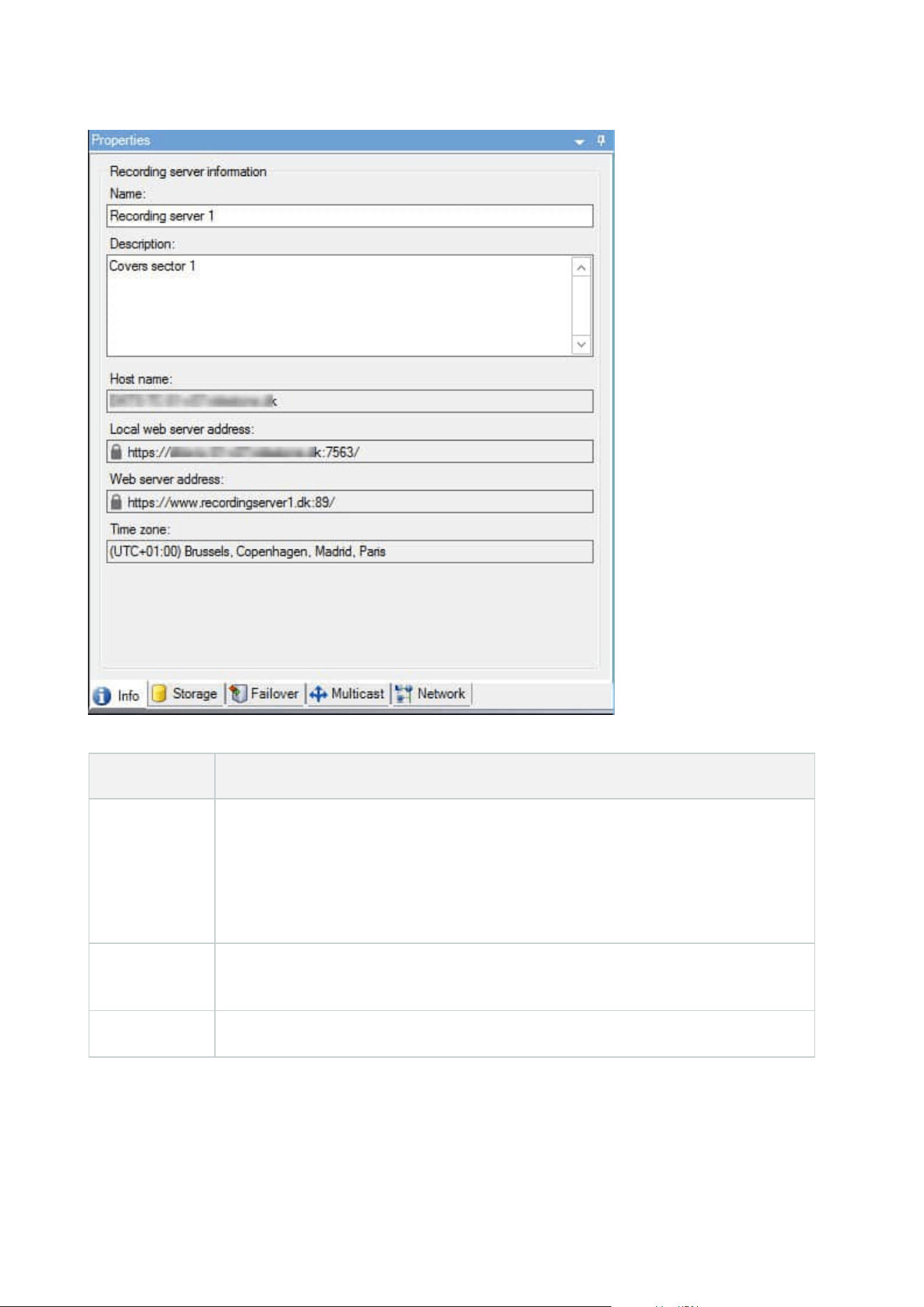
Name Description
Name
You can choose to enter a name for the recording server. The name is used in the
system and clients when the recording server is listed. The name does not have to be
unique.
When you rename a recording server, the name is changed globally in the Management
Client.
Description
You can choose to enter a description that appears in a number of listings within the
system. A description is not mandatory.
Host name Displays the recording server's host name.
Administrator manual | XProtect® VMS 2023 R1
396 | User interface details

Name Description
Local web
server address
Displays the local address of the recording server's web server. You use the local
address, for example, for handling PTZ camera control commands, and for handling
browsing and live requests from XProtect Smart Client.
The address includes the port number that is used for web server communication
(typically port 7563).
If you enable encryption to clients and servers that retrieve data streams from the
recording server, a padlock icon appears, and the address includes https instead of
http.
Web server
address
Displays the public address of the recording server's web server over the internet.
If your installation uses a firewall or NAT router, enter the address of the firewall or NAT
router so that clients that access the surveillance system on the internet can connect to
the recording server.
You specify the public address and port number on the Network tab.
If you enable encryption to clients and servers that retrieve data streams from the
recording server, a padlock icon appears, and the address includes https instead of
http.
Time zone Displays the time zone that the recording server is located in.
Storage tab (recording server)
On the Storage tab, you can set up, manage and view storages for a selected recording server.
For recording storages and archives, the horizontal bar shows the current amount of free space. You can
specify the behavior of the recording server in case recording storages become unavailable. This is mostly
relevant if your system includes failover servers.
If you are using Evidence lock, there will be a vertical red line showing the space used for evidence locked
footage.
Administrator manual | XProtect® VMS 2023 R1
397 | User interface details

Storage and Recording Settings properties
Available functionality depends on the system you are using. See the complete feature list, which is available
on the product overview page on the Milestone website
(https://www.milestonesys.com/solutions/platform/product-index/).
In the Storage and Recording Settings dialog box, specify the following:
Administrator manual | XProtect® VMS 2023 R1
398 | User interface details
Name Description
Name Rename the storage if needed. Names must be unique.
Path
Specify the path to the directory to which you save recordings in this storage. The
storage does not necessarily have to be located on the recording server computer.
If the directory does not exist, you can create it. Network drives must be specified by
using UNC (Universal Naming Convention) format, example: \\server\volume\directory\.
Retention
time
Specify for how long recordings should stay in the archive before they are deleted or
moved to the next archive (depending on archive settings).
The retention time must always be longer than the retention time of the previous
archive or the default recording database. This is because the number of retention days
specified for an archive includes all the retention periods stated earlier in the process.
Maximum
size
Select the maximum number of gigabytes of recording data to save in the recording
database.
Recording data in excess of the specified number of gigabytes is auto-moved to the first
archive in the list - if any is specified - or deleted.
When less than 5GB of space is free, the system always auto-
archives (or deletes if no next archive is defined) the oldest data in
a database. If less than 1GB space is free, data is deleted. A
database always requires 250MB of free space. If you reach this
limit (if data is not deleted fast enough), no more data is written to
the database until you have freed enough space. The actual
maximum size of your database is the amount of gigabytes you
specify, minus 5GB.
Signing
Enables a digital signature to the recordings. This means, for example, that the system
confirms that exported video has not been modified or tampered with when played
back.
The system uses the SHA-2 algorithm for digital signing.
Encryption
Select the encryption level of the recordings:
l
None
Administrator manual | XProtect® VMS 2023 R1
399 | User interface details

Name Description
l
Light (less CPU usage)
l
Strong (more CPU usage)
The system uses the AES-256 algorithm for encryption.
If you select Light, a part of the recording is encrypted. If you select Strong, the whole
recording is encrypted.
If you choose to enable encryption, you must also specify a password below.
Password
Enter a password for the users allowed to view encrypted data.
Milestone recommends that you use strong passwords. Strong passwords do not
contain words that can be found in a dictionary or are part of the user's name. They
include eight or more alpha-numeric characters, upper and lower cases, and special
characters.
Archive Settings properties
In the Archive Settings dialog box, specify the following:
Name Description
Name Rename the storage if needed. Names must be unique.
Path
Specify the path to the directory to which you save recordings in this storage. The
storage does not necessarily have to be located on the recording server computer.
If the directory does not exist, you can create it. Network drives must be specified by
using UNC (Universal Naming Convention) format, example: \\server\volume\directory\.
Retention
time
Specify for how long recordings should stay in the archive before they are deleted or
moved to the next archive (depending on archive settings).
The retention time must always be longer than the retention time of the previous archive
or the default recording database. This is because the number of retention days specified
Administrator manual | XProtect® VMS 2023 R1
400 | User interface details
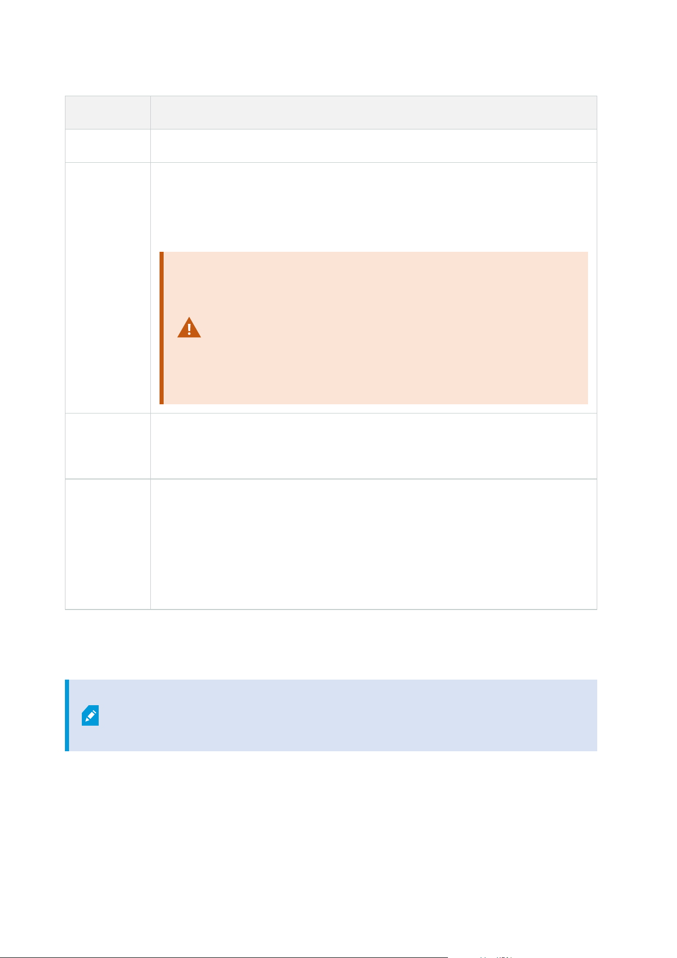
Name Description
for an archive includes all the retention periods stated earlier in the process.
Maximum
size
Select the maximum number of gigabytes of recording data to save in the recording
database.
Recording data in excess of the specified number of gigabytes is auto-moved to the first
archive in the list - if any is specified - or deleted.
When less than 5GB of space is free, the system always auto-
archives (or deletes if no next archive is defined) the oldest data in
a database. If less than 1GB space is free, data is deleted. A
database always requires 250MB of free space. If you reach this
limit (if data is not deleted fast enough), no more data is written to
the database until you have freed enough space. The actual
maximum size of your database is the amount of gigabytes you
specify, minus 5GB.
Schedule
Specify an archiving schedule that outlines the intervals with which the archiving process
should start. You can archive very frequently (in principle every hour all year round), or
very infrequently (for example, every first Monday of every 36 months).
Reduce
frame rate
To reduce FPS when archiving, select the Reduce frame rate check box and set a frame
per second (FPS).
Reduction of frame rates by a selected number of FPS makes your recordings take up
less space in the archive, but it also reduces the quality of your archive.
MPEG-4/H.264/H.265 reduces automatically to key-frames as a minimum.
0.1 = 1 frame per 10 seconds.
Failover tab (recording server)
Available functionality depends on the system you are using. See the complete feature
list, which is available on the product overview page on the Milestone website
(https://www.milestonesys.com/solutions/platform/product-index/).
If your organization uses failover recording servers, use the Failover tab to assign failover servers to recording
servers, see Failover tab properties.
Administrator manual | XProtect® VMS 2023 R1
401 | User interface details
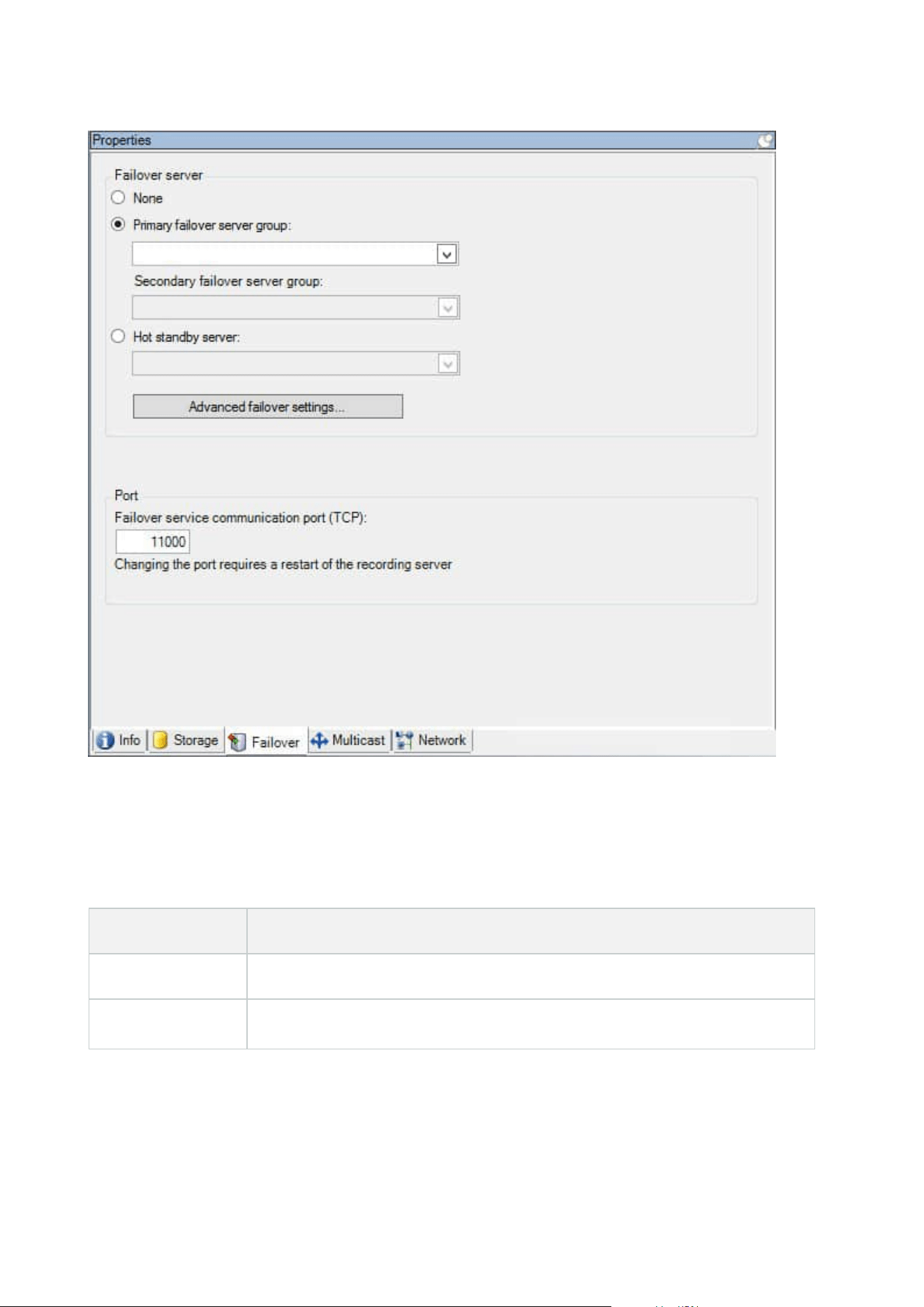
For details on failover recording servers, installation and settings, failover groups and their settings, see
Failover recording server (explained) on page 37.
Failover tab properties
Name Description
None Select a setup without failover recording servers.
Primary failover
Select a regular failover setup with one primary and possibly one secondary
Administrator manual | XProtect® VMS 2023 R1
402 | User interface details
Name Description
server group /
Secondary failover
server group
failover server group.
Hot standby server
Select a hot standby setup with one dedicated recording server as hot standby
server.
Advanced failover
settings
Opens the Advanced Failover Settings window:
l
Full Support: Enables full failover support for the device
l
Live Only: Enables only failover support for live streams on the device
l
Disabled: Disables failover support for the device
Failover service
communication
port (TCP)
By default, the port number is 11000. You use this port for communication
between recording servers and failover recording servers. If you change the port,
the recording server must be running and must be connected to the management
server.
Multicast tab (recording server)
Your system supports multicasting of live streams from recording servers. If multiple XProtect Smart Client
users want to view live video from the same camera, multicasting helps saving considerable system resources.
Multicasting is particularly useful if you use the Matrix functionality, where multiple clients require live video
from the same camera.
Multicasting is only possible for live streams, not for recorded video/audio.
If a recording server has more than one network interface card, it is only possible to use
multicast on one of them. Through the Management Client you can specify which one to use.
If you are using failover servers, remember to also specify the IP address of the network
interface card on the failover servers (see Multicast tab (failover server) on page 410).
Administrator manual | XProtect® VMS 2023 R1
403 | User interface details
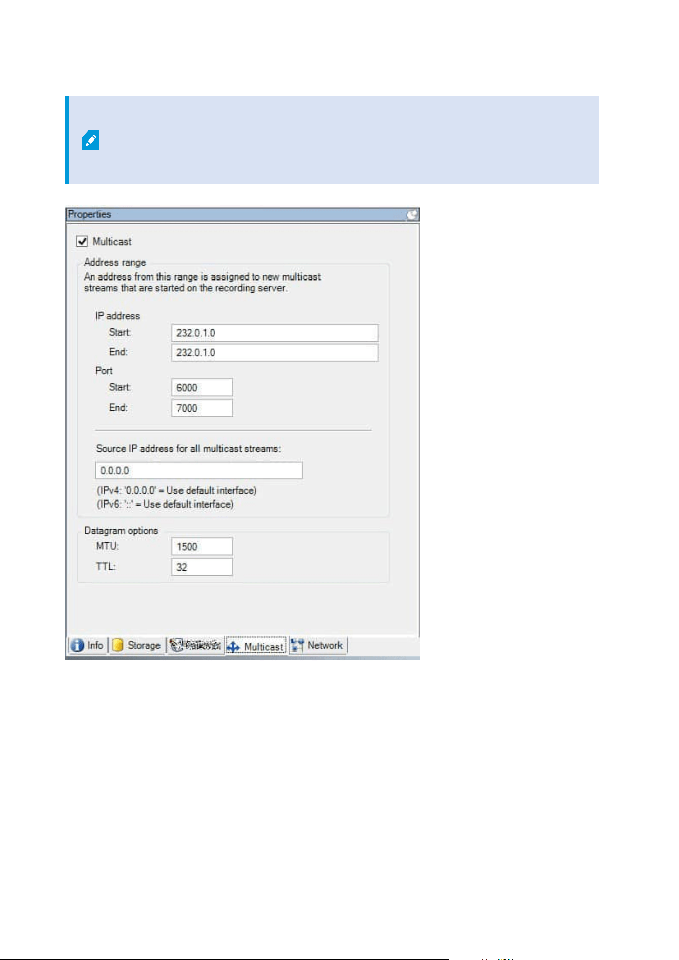
The successful implementation of multicasting also requires that you have set up your
network equipment to relay multicast data packets to the required group of recipients
only. If not, multicasting may not be different from broadcasting, which can significantly
slow down network communication.
Assign IP address range
Specify the range you want to assign as addresses for multicast streams from the selected recording server.
The clients connect to these addresses when the users view multicast video from the recording server.
Administrator manual | XProtect® VMS 2023 R1
404 | User interface details
For each multicast camera feed, the IP address and port combination must be unique (IPv4 example:
232.0.1.0:6000). You can either use one IP address and many ports, or many IP addresses and fewer ports. By
default, the system suggests a single IP address and a range of 1000 ports, but you can change this as
required.
IP addresses for multicasting must be within the range defined for dynamic host allocation by IANA. IANA is
the authority overseeing global IP address allocation.
Name Description
IP address
In the Start field, specify the first IP address in the required range. Then specify the last IP
address in the range in the End field.
Port
In the Start field, specify the first port number in the required range. Then specify the last
port number in the range in the End field.
Source IP
address for
all multicast
streams
You can only multicast on one network interface card, so this field is relevant if your
recording server has more than one network interface card or if it has a network interface
card with more than one IP address.
To use the recording server's default interface, leave the value 0.0.0.0 (IPv4) or :: (IPv6) in
the field. If you want to use another network interface card, or a different IP address on
the same network interface card, specify the IP address of the required interface.
l
IPv4: 224.0.0.0 to 239.255.255.255.
l
IPv6, the range is described on the IANA website (https://www.iana.org/).
Specify datagram options
Specify the settings for data packets (datagrams) transmitted through multicasting.
Name Description
MTU
Maximum Transmission Unit, the largest allowed physical data packet size (measured in
bytes). Messages larger than the specified MTU are split into smaller packets before they are
sent. The default value is 1500, which is also the default on most Windows computers and
Ethernet networks.
Administrator manual | XProtect® VMS 2023 R1
405 | User interface details
Name Description
TTL
Time To Live, the largest allowed number of hops a data packet should be able to travel
before it is discarded or returned. A hop is a point between two network devices, typically a
router. Default value is 128.
Network tab (recording server)
If you need to access the VMS with XProtect Smart Client over a public or untrusted
network, Milestone recommends that you use a secure connection through VPN. This
helps ensure that communication between XProtect Smart Client and the VMS server is
protected.
You define a recording server's public IP address on the Network tab.
Why use a public address?
Clients may connect from the local network as well as from the Internet, and in both cases the surveillance
system must provide suitable addresses so the clients can get access to live and recorded video from the
recording servers:
l
When clients connect locally, the surveillance system should reply with local addresses and port
numbers
l
When clients connect from the internet, the surveillance system should reply with the recording server's
public address. This is the address of the firewall or NAT (Network Address Translation) router, and
often also a different port number. The address and the port can then be forwarded to the server's local
address and port.
Failover Servers (Servers node)
Available functionality depends on the system you are using. See the complete feature
list, which is available on the product overview page on the Milestone website
(https://www.milestonesys.com/solutions/platform/product-index/).
A failover recording server is an extra recording server which takes over from the standard recording server if
this becomes unavailable. You can configure a failover recording server in two modes, as a cold standby
server or as a hot standby server.
Administrator manual | XProtect® VMS 2023 R1
406 | User interface details
You install failover recording servers like standard recording servers (see Install a failover recording server
through Download Manager on page 161). Once you have installed failover recording servers, they are visible
in the Management Client. Milestone recommends that you install all failover recording servers on separate
computers. Make sure that you configure failover recording servers with the correct IP address/host name of
the management server. The user permissions for the user account under which the Failover Server service
runs are provided during the installation process. They are:
l
Start/Stop permissions to start or stop the failover recording server
l
Read and Write access permissions to read or write the RecorderConfig.xml file
If a certificate is selected for encryption, then the administrator must grant read access permission to the
failover user on the selected certificate private key.
If the failover recording server takes over from a recording server that uses encryption,
Milestone recommends that you also prepare the failover recording server for using
encryption. For more information, see Secure communication (explained) on page 138
and Install a failover recording server through Download Manager on page 161.
You can specify what type of failover support you want on device-level. For each device on a recording server,
select full, live only or no failover support. This helps you prioritize your failover resources and, for example,
only set up failover for video and not for audio, or only have failover on essential cameras, not on less
important ones.
While your system is in failover mode, you cannot replace or move hardware, update the
recording server, or change device configurations such as storage settings or video
stream settings.
Cold standby failover recording servers
In a cold standby failover recording server setup, you group multiple failover recording servers in a failover
group. The entire failover group is dedicated to take over from any of several preselected recording servers, if
one of these becomes unavailable. You can create as many groups as you want (see Group failover recording
servers for cold standby on page 201).
Grouping has a clear benefit: when you later specify which failover recording servers should take over from a
recording server, you select a group of failover recording servers. If the selected group contains more than
one failover recording server, this offers you the security of having more than one failover recording server
ready to take over if a recording server becomes unavailable. You can specify a secondary failover server group
that takes over from the primary group if all the recording servers in the primary group are busy. A failover
recording server can only be a member of one group at a time.
Administrator manual | XProtect® VMS 2023 R1
407 | User interface details
Failover recording servers in a failover group are ordered in a sequence. The sequence determines the order in
which the failover recording servers will take over from a recording server. By default, the sequence reflects
the order in which you have incorporated the failover recording servers in the failover group: first in is first in
the sequence. You can change this if you need to.
Hot standby failover recording servers
In a hot standby failover recording server setup, you dedicate a failover recording server to take over from one
recording server only. Because of this, the system can keep this failover recording server in a "standby" mode
which means that it is synchronized with the correct/current configuration of the recording server it is
dedicated to and can take over much faster than a cold standby failover recording server. As mentioned, you
assign hot standby servers to one recording server only and cannot group it. You cannot assign failover
servers that are already part of a failover group as hot standby recording servers.
Failover recording server validation
To validate a merge of video data from the failover server to the recording server, you
must make the recording server unavailable by either stopping the recording server
service or shutting down the recording server computer.
Any manual interruption of the network that you can cause by pulling out the network
cable or blocking the network using a test tool is not a valid method.
Info tab properties (failover server)
Specify the following failover recording server properties:
Name Description
Name
The name of the failover recording server as it appears in the Management Client, logs
and more.
Description
An optional field that you can use to describe the failover recording server, for example
which recording server it takes over from.
Host name Displays the failover recording server's host name. You cannot change this.
Administrator manual | XProtect® VMS 2023 R1
408 | User interface details

Name Description
Local web
server address
Displays the local address of the failover recording server's web server. You use the
local address, for example, for handling PTZ camera control commands, and for
handling browsing and live requests from XProtect Smart Client.
The address includes the port number that is used for web server communication
(typically port 7563).
If the failover recording server takes over from a recording server that uses encryption,
you also need to prepare the failover recording server to use encryption.
If you enable encryption to clients and servers that retrieve data streams from the
recording server, a padlock icon appears, and the address includes https instead of
http.
Web server
address
Displays the public address of the failover recording server's web server on the
internet.
If your installation uses a firewall or NAT router, enter the address of the firewall or NAT
router so that clients that access the surveillance system on the internet can connect to
the failover recording server.
You specify the public address and port number on the Network tab.
If you enable encryption to clients and servers that retrieve data streams from the
recording server, a padlock icon appears, and the address includes https instead of
http.
UDP port
The port number used for communication between failover recording servers. Default
port is 8844.
Database
location
Specify the path to the database used by the failover recording server for storing
recordings.
You cannot change the database path while the failover recording server is taking over
from a recording server. The system applies the changes when the failover recording
server is no longer taking over from a recording server.
Enable this
failover server
Clear to disable the failover recording server (selected by default). You must disable
failover recording servers before they can take over from recording servers.
Administrator manual | XProtect® VMS 2023 R1
409 | User interface details
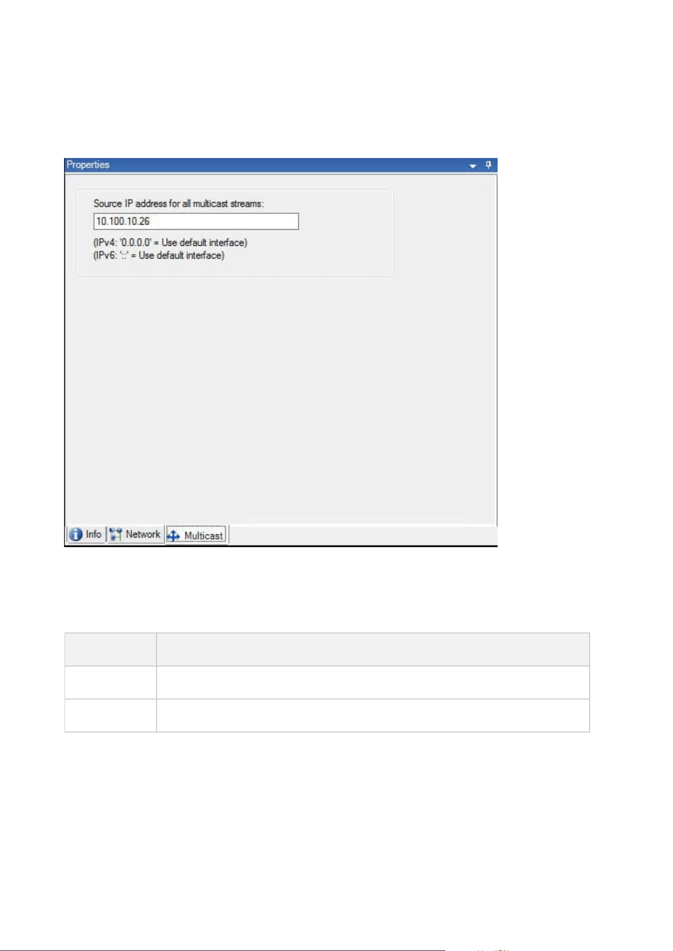
Multicast tab (failover server)
If you are using failover servers, and you have enabled multicasting of live streaming, you must specify the IP
address of the network interface card you are using, on both the recording servers and the failover servers.
For more information about multicasting, see Enable multicasting for the recording server on page 197.
Info tab properties (failover group)
Field Description
Name The name of the failover group as it appears in the Management Client, logs and more.
Description An optional description, for example the server's physical location.
Administrator manual | XProtect® VMS 2023 R1
410 | User interface details

Sequence tab properties (failover group)
Field Description
Specify the failover
sequence
Use Up and Down to set the wanted sequence of regular failover recording
servers within the group.
Remote server for Milestone Interconnect
Milestone Interconnect™ allows you to integrate a number of smaller, physically fragmented, and remote
XProtect installations with one XProtect Corporate central site. You can install these smaller sites, called
remote sites, on mobile units, for example, boats, busses or trains. This means that such sites do not need to
be permanently connected to a network.
Info tab (remote server)
Name Description
Name
The system uses the name whenever the remote server is listed in the system and
clients. The name does not have to be unique.
When you rename a server, the name is changed globally in the Management Client.
Description
Enter a description of the remote server (optional).
The description appears in a number of listings within the system. For example, when
pausing the mouse pointer over the hardware name in the Overview pane.
Model Displays the XProtect product installed at the remote site.
Version Displays the version of the remote system.
Software
license code
The software license code of the remote system.
Driver Identifies the driver that handles the connection to the remote server.
Address The host name or IP address of the hardware.
Administrator manual | XProtect® VMS 2023 R1
411 | User interface details
Name Description
IE
Opens the default home page of the hardware vendor. You can use this page for
administration of the hardware or system.
Remote
system ID
The unique system ID of the remote site used by XProtect to, for example, manage
licenses.
Settings tab (remote server)
On the Settings tab, you can view the name of the remote system.
Events tab (remote server)
You can add events from the remote system to your central site in order to create rules and thereby respond
immediately to events from the remote system. The number of events depend on the events configured in the
remote system. You cannot delete default events.
If the list appears to be incomplete:
1. Right-click the relevant remote server in the Overview pane and select Update Hardware.
2. The dialog box lists all changes (devices removed, updated and added) in the remote system since you
established or last refreshed the Milestone Interconnect setup. Click Confirm to update your central
site with these changes.
Remote Retrieval tab
On the Remote Retrieval tab, you can handle remote recording retrieval settings for the remote site in a
Milestone Interconnect setup:
Specify the following properties:
Name Description
Retrieve
recordings at
max
Determines the maximum bandwidth in Kbits/s to be used for retrieving recordings
from a remote site. Select the check box to enable limiting retrievals.
Retrieve
Determines that retrieval of recordings from a remote site are limited to a specific time
Administrator manual | XProtect® VMS 2023 R1
412 | User interface details
Name Description
recordings
between
interval.
Unfinished jobs at the end time continue until completion, so if the end time is critical,
you need to set it earlier to allow for unfinished jobs to complete.
If the system receives an automatic retrieval or request for retrieval from the XProtect
Smart Client outside the time interval, it is accepted, but not started until the selected
time interval is reached.
You can view pending remote recording retrieval jobs initiated by the users from System
Dashboard -> Current Tasks.
Retrieve on
devices in
parallel
Determines the maximum number of devices from which recordings are retrieved
simultaneously. Change the default value if you need more or less capacity depending
on your system's capabilities.
When you change the settings, it may take several minutes until the changes are reflected in the system.
None of the above applies to direct playback of remote recordings.
All cameras set to be played back directly is available for direct playback and use
bandwidth as needed.
Devices node
Devices (Devices node)
The devices appear in the Management Client when you add hardware with the Add Hardware wizard.
You can manage devices via the device groups if they have the same properties, see Device groups (explained)
on page 53.
You can also manage the devices individually.
Enabling/disabling and renaming of individual devices take place on the recording server hardware. See
Enable/disable devices via device groups.
For all other configuration and management of cameras, expand Devices in the Site Navigation pane, then
select a device:
Administrator manual | XProtect® VMS 2023 R1
413 | User interface details
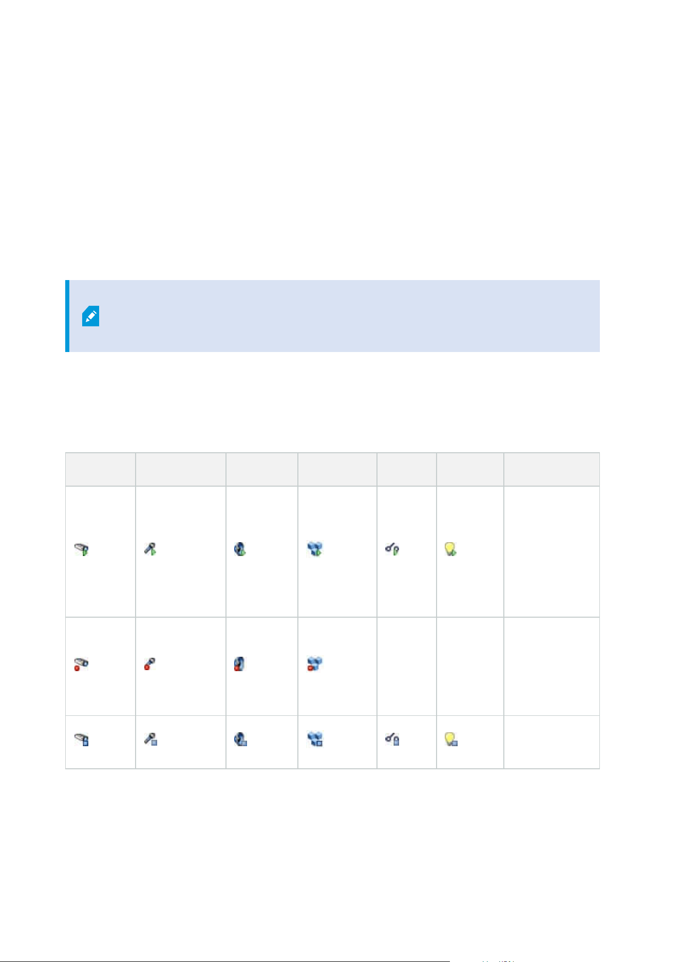
l
Cameras
l
Microphones
l
Speakers
l
Metadata
l
Inputs
l
Outputs
In the Overview pane, you group your cameras for an easy overview of your cameras. Initial grouping is done
as part of the Add hardware wizard.
For information about supported hardware, see the supported hardware page on the
Milestone website (https://www.milestonesys.com/support/tools-and-
references/supported-devices/).
Status icons of devices
When you select a device, information about the current status appears in the Preview pane.
The following icons indicate the status of the devices:
Camera Microphone Speaker Metadata Input Output Description
Device enabled
and retrieving
data: The
device is
enabled and
you retrieve a
live stream.
Device
recording: The
device is
recording data
on the system.
Device
Administrator manual | XProtect® VMS 2023 R1
414 | User interface details

Camera Microphone Speaker Metadata Input Output Description
temporarily
stopped or has
no feed: When
stopped, no
information is
transferred to
the system. If it
is a camera, you
cannot view live
video. A
stopped device
can still
communicate
with the
recording
server for
retrieving
events, setting
settings etc., as
opposed to
when a device
is disabled.
Devices
disabled:
Cannot be
started
automatically
through a rule
and cannot
communicate
with the
recording
server. If a
camera is
disabled, you
cannot view live
or recorded
video.
Administrator manual | XProtect® VMS 2023 R1
415 | User interface details
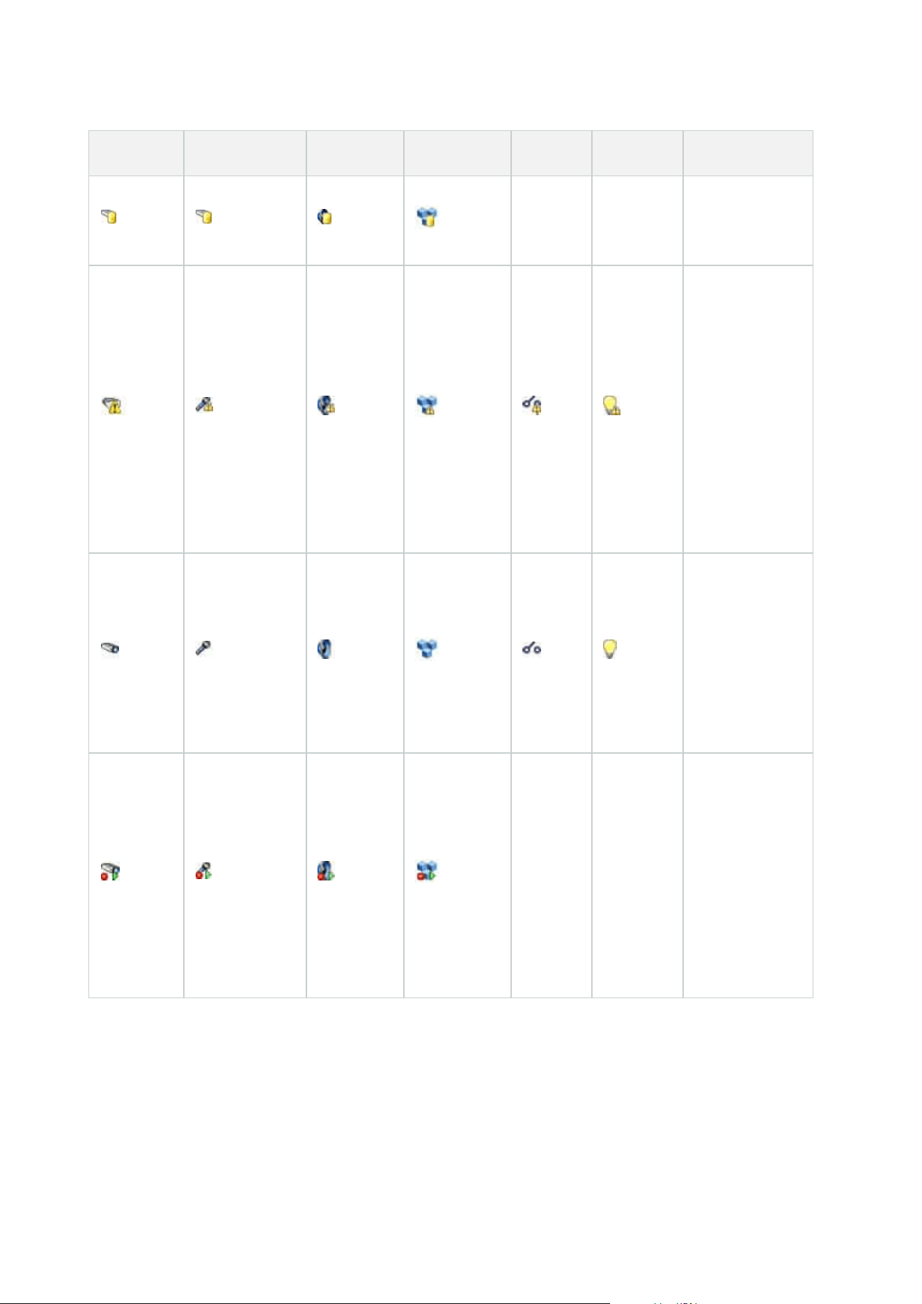
Camera Microphone Speaker Metadata Input Output Description
Device
database being
repaired.
Device requires
attention: The
device does not
function
correctly. Pause
the mouse
pointer over the
device icon to
get a
description of
the problem in
the tooltip.
Status
unknown:
Status of the
device is
unknown, for
example, if the
recording
server is offline.
Some icons can
be combined,
as in this
example where
Device enabled
and retrieving
data is
combined with
Device
recording.
Cameras (Devices node)
Camera devices are added automatically when you add hardware to the system and are by default enabled.
Administrator manual | XProtect® VMS 2023 R1
416 | User interface details

The system comes with a default start feed rule which ensures that video feeds from all connected cameras are
automatically fed to the system. The default rule can be deactivated and/or modified as required.
Follow this configuration order to complete the most typical tasks related to configuration of a camera device:
1. Configure camera settings, see Settings tab (devices.
2. Configure streams, see Streams tab (devices).
3. Configure motion, see Motion tab (devices).
4. Configure recording, see Record tab (devices) and Monitor the databases for devices.
5. Configure the remaining settings as needed.
Microphones (Devices node)
Microphone devices are added automatically when you add hardware to the system. They are by default
disabled, so you must enable them before use, either as part of the Add Hardware wizard or afterwards.
Microphones do not require separate licenses. You can use as many microphones as required on your system.
You can use microphones completely independently of cameras.
The system comes with a default start audio feed rule which ensures that audio feeds from all connected
microphones are automatically fed to the system. The default rule can be deactivated and/or modified as
required.
You can configure microphone devices on these tabs:
l
Info tab, see Info tab (devices)
l
Settings tab, see Settings tab (devices)
l
Record tab, see Record tab (devices)
l
Events tab, see Events tab (devices)
Speakers (Devices node)
Speaker devices are added automatically when you add hardware to the system. They are by default disabled,
so you must enable them before use, either as part of the Add Hardware wizard or afterwards. Speakers do
not require separate licenses. You can use as many speakers as required on your system.
You can use speakers completely independently of cameras.
The system comes with a default start audio feed rule that starts the device so the device is ready to send user
activated audio to the speakers. The default rule can be deactivated and/or modified as required.
You can configure speaker devices on these tabs:
l
Info tab, see Info tab (devices)
l
Settings tab, see Settings tab (devices)
l
Record tab, see Record tab (devices)
Administrator manual | XProtect® VMS 2023 R1
417 | User interface details

Metadata (Devices node)
The system comes with a default start feed rule which ensures that metadata feeds from all connected
hardware that supports metadata, are automatically fed to the system. The default rule can be deactivated
and/or modified as required.
You can configure metadata devices on these tabs:
l
Info tab, see Info tab (devices)
l
Settings tab, see Settings tab (devices)
l
Record tab, see Record tab (devices)
Input (Devices node)
You can use input devices completely independently of cameras.
Before you specify use of external input units on a device, verify that the device itself
recognize the sensor operation. Most devices can show this in their configuration
interfaces, or via Common Gateway Interface (CGI) script commands.
Input devices are added automatically when you add hardware to the system. They are by default disabled, so
you must enable them before use, either as part of the Add Hardware wizard or afterwards. Input devices do
not require separate licenses. You can use as many input devices as required on your system.
You can configure input devices on these tabs:
l
Info tab, see Info tab (devices)
l
Settings tab, see Settings tab (devices)
l
Events tab, see Events tab (devices)
Output (Devices node)
Output can be triggered manually from the Management Client and XProtect Smart Client.
Before you specify use of external output units on a device, verify that the device itself
can control the device attached to the output. Most devices can show this in their
configuration interfaces, or via Common Gateway Interface (CGI) script commands.
Output devices are added automatically when you add hardware to the system. They are by default disabled,
so you must enable them before use, either as part of the Add Hardware wizard or afterwards. Output devices
do not require separate licenses. You can use as many output devices as required on your system.
You can configure output devices on these tabs:
Administrator manual | XProtect® VMS 2023 R1
418 | User interface details
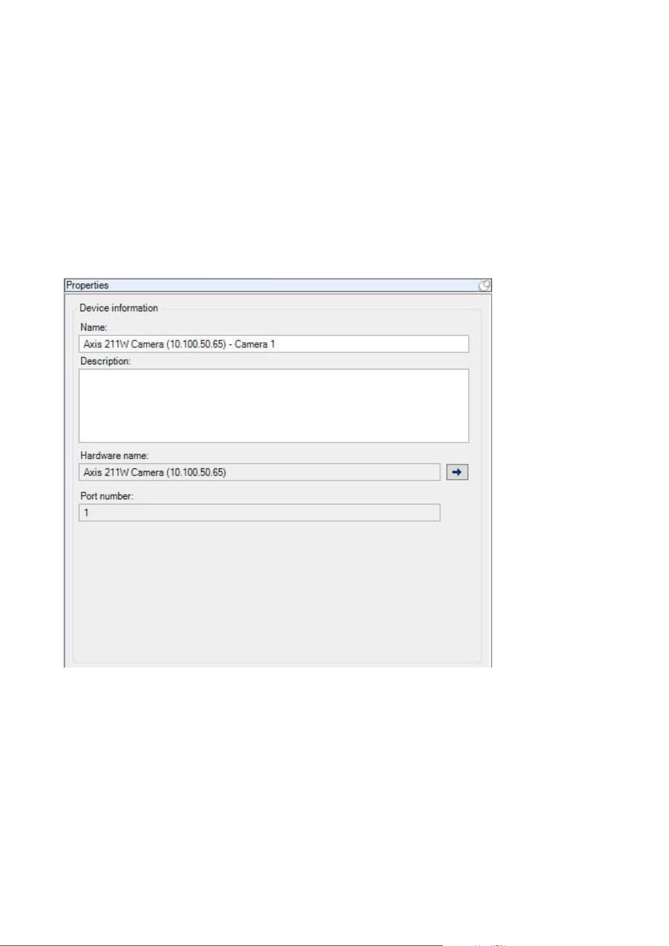
Info tab, see
l
Info tab, see Info tab (devices)
l
Settings tab, see Settings tab (devices)
Devices tabs
Info tab (devices)
On the Info tab, you can view and edit basic information about a device in a number of fields.
All devices have an Info tab.
Administrator manual | XProtect® VMS 2023 R1
419 | User interface details
Info tab properties
Name Description
Name
The name is used whenever the device is listed in the system and clients.
When you rename a device, the name is changed globally in the Management Client.
Description
Enter a description of the device (optional).
The description appears in a number of listings within the system. For example, when
you pause the mouse pointer over the name in the Overview pane.
Hardware
name
Displays the name of the hardware, with which the device is connected. The field is
non-editable from here, but you can change it by clicking Go To next to it. This takes
you to hardware information where you can change the name.
Port number
Displays the port on which the device is attached on the hardware.
For single-device hardware, the port number is typically 1. For multi-device hardware,
such as video servers with several channels, the port number typically indicates the
channel on which the device is attached, for example 3.
Short name
To apply a short name for the camera, enter it here. The maximum length of characters
is 128.
If you are using smart map, automatically the short name is displayed with the camera
on the smart map. Otherwise the full name is displayed.
Geo
coordinates
Enter the geographic location of the camera in the format latitude, longitude. The
value you enter determines the position of the camera icon on the smart map in
XProtect Smart Client.
The field is mainly for smart map and third party integrations.
Direction
Enter the viewing direction of the camera measured against a due north point on a
vertical axis. The value you enter determines the direction of the camera icon on the
smart map in XProtect Smart Client.
The default value is 0.0.
Administrator manual | XProtect® VMS 2023 R1
420 | User interface details
Name Description
The field is mainly for smart map and third party integrations.
Field of view
Enter the field of view in degrees. The value you enter determines the field of view of
the camera icon on the smart map in XProtect Smart Client.
The default value is 0.0.
The field is mainly for smart map and third party integrations.
Depth
Enter the depth of the camera in meters or feet. The value you enter determines the
depth of the camera icon on the smart map in XProtect Smart Client.
The default value is 0.0.
The field is mainly for smart map and third party integrations.
Preview
position in
browser
To verify that you have entered the correct geographic coordinates, click the button.
Google Maps will open in your standard Internet browser on the position you specify.
The field is mainly for smart map and third party integrations.
Settings tab (devices)
On the Settings tab, you can view and edit settings for a device in a number of fields.
All devices have a Settings tab.
The values appear in a table as changeable or read-only. When you change a setting to a non-default value, the
value appears in bold.
The content of the table depends on the device driver.
Allowed ranges appear in the information box below the settings table:
Administrator manual | XProtect® VMS 2023 R1
421 | User interface details
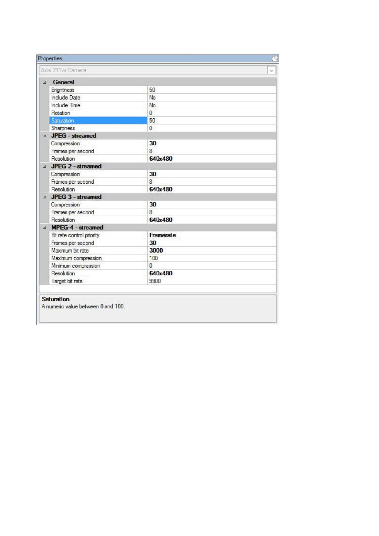
For more information about camera settings, see View or edit camera settings.
Streams tab (devices)
The following devices have a Streams tab:
l
Cameras
The Streams tab lists by default a single stream. It is the selected camera's default stream, used for live and
recorded video.
Administrator manual | XProtect® VMS 2023 R1
422 | User interface details
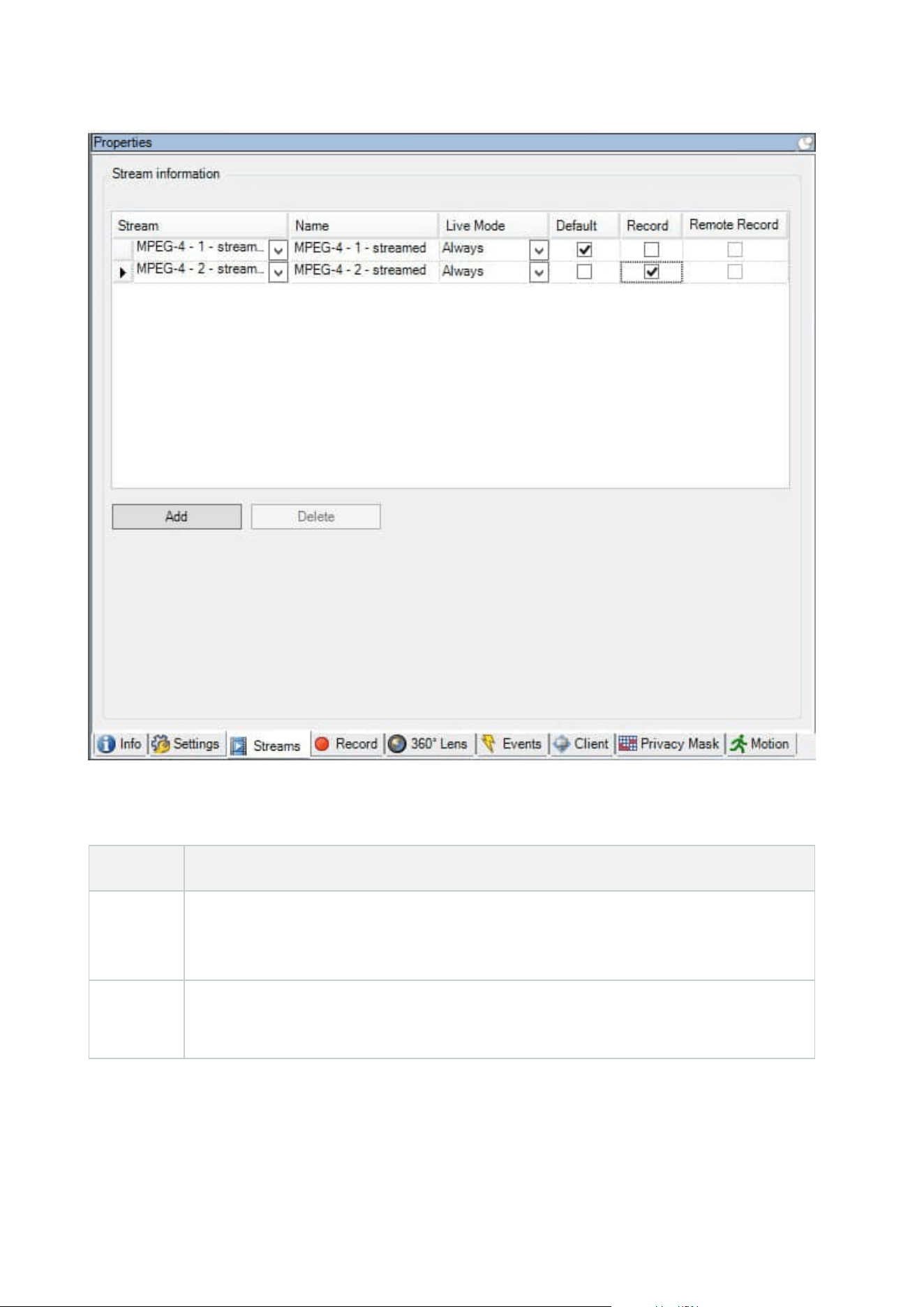
Tasks on the Streams tab
Name Description
Record
Select this check box to change which stream to use for recording. For live streaming, you
can set up and use as many live streams as the camera supports, but you can only select one
stream for recording at a time.
Add
Click to add a stream to the list.
Add a stream
Administrator manual | XProtect® VMS 2023 R1
423 | User interface details

Record tab (devices)
The following devices have a Record tab:
l
Cameras
l
Microphones
l
Speakers
l
Metadata
Recordings from a device are only saved in the database when you have enabled recording and the recording-
related rule criteria are met.
Parameters that cannot be configured for a device are grayed out.
Administrator manual | XProtect® VMS 2023 R1
424 | User interface details
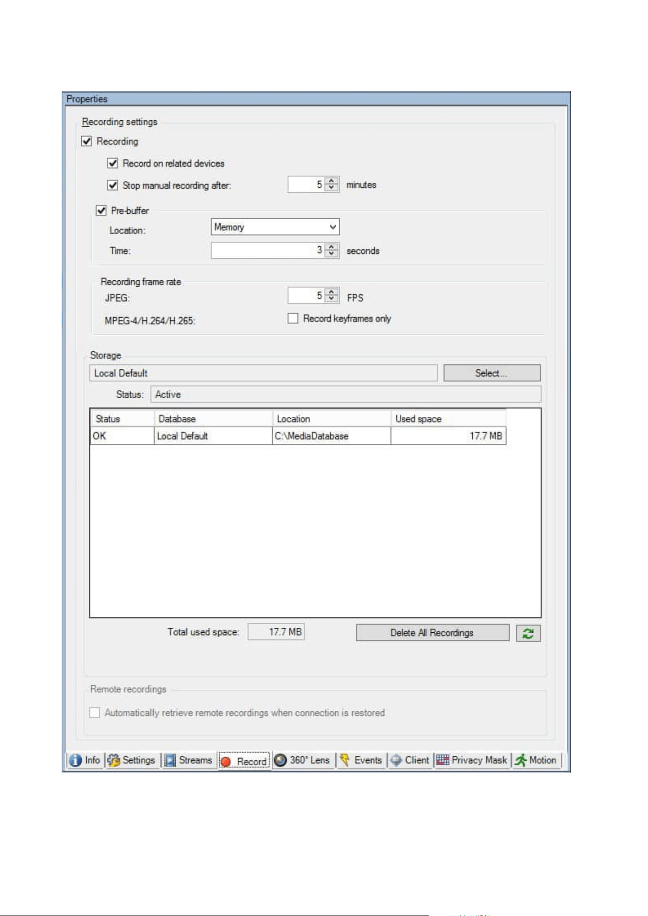
Administrator manual | XProtect® VMS 2023 R1
425 | User interface details

Tasks on the Record tab
Name Description
Recording
Enable/disable recording
Enable recording on related devices
Pre-buffer
Pre-buffering and storage of pre-buffer recordings
(explained)
Manage pre-buffering
Manage manual recording
Recording frame
rate
Specify recording frame rate
Enable keyframe recording
Storage Monitor the status of databases for devices
Select Move devices from one storage to another
Delete All
Recordings
Use this button if you have added all devices in the group to
the same server:
Delete recordings
Automatically
retrieve remote
recordings when
connection is
restored
Save and retrieve remote recording
Motion tab (devices)
The following devices have a Motion tab:
l
Cameras
On the Motion tab, you can enable and configure motion detection for the selected camera.
Administrator manual | XProtect® VMS 2023 R1
426 | User interface details
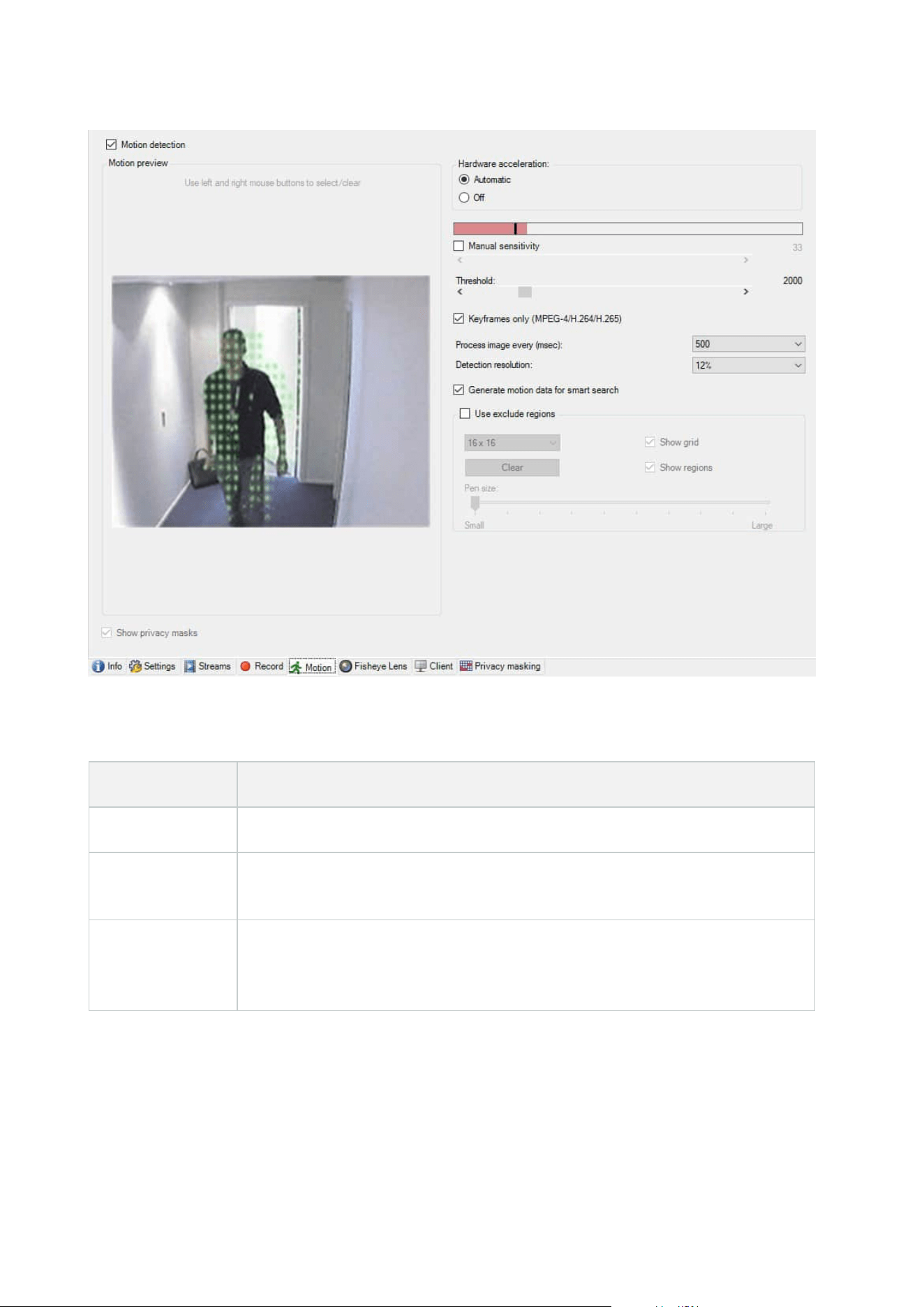
Tasks on the Motion tab
Name Description
Motion detection Enable and disable motion detection
Hardware
acceleration
Select Automatic to enable hardware acceleration or select Off to disable the
setting. For more information, see Enable or disable hardware acceleration.
Privacy masks
If you have defined areas with permanent privacy masks, you can select the Privacy
masks check box to display the privacy masks on the Motion tab. You define areas
with privacy masks on the Privacy masking tab (devices) on page 441.
Administrator manual | XProtect® VMS 2023 R1
427 | User interface details

Name Description
There is no motion detection within areas covered by
permanent privacy masks.
Manual
sensitivity
Determine how much each pixel in the image must change before it is regarded as
motion:
Enable manual sensitivity to define motion
Threshold
Determine how many pixels in the image must change before it is regarded as
motion:
Specify threshold to define motion
Keyframes only
(MPEG-
4/H.264/H.265)
Select this check box to do motion detection on keyframes only instead of on the
entire video stream. Only applies to MPEG-4/H.264/H.265.
Motion detection on keyframes reduces the amount of processing power used to
carry out the analysis.
Process image
every (msec)
Select an image processing interval in this list to determine how often the system
performs the motion detection analysis.
For example, every 1000 milliseconds are once every second. Default value is every
500 milliseconds.
The interval is applied if the actual frame rate is higher than the interval you set
here.
Detection
resolution
Select a detection resolution in this list to optimize motion detection performance.
Only the selected percentage of the image is analyzed, for example 25%. By
analyzing 25%, only every fourth pixel in the image is analyzed instead of all pixels.
Using optimized detection reduces the amount of processing power used to carry
out the analysis, but also means a less accurate motion detection.
Generate motion
data for smart
search
With this check box enabled, the system generates motion data for the images used
for motion detection. For example, if you select motion detection on keyframes only,
the motion data is also produced for keyframes only.
The extra motion data enables the client user, via the smart search function, to
Administrator manual | XProtect® VMS 2023 R1
428 | User interface details

Name Description
quickly search for relevant recordings based on motion in the selected area of the
image. The system does not generate motion data within areas covered by
permanent privacy masks, but only for areas with liftable privacy masks (see Motion
detection (explained)).
Motion detection threshold and exclude regions do not influence the generated
motion data.
l
Specify the default setting of generating smart search data for cameras
under Tools > Options > General.
Use exclude
regions
Exclude motion detection from specific areas of a camera view:
Specify exclude regions for motion detection
Presets tab (devices)
The following devices have a Presets tab:
l
PTZ cameras that support preset positions
On the Presets tab, you can create or import preset positions, for example:
l
In rules for making a PTZ (pan-tilt-zoom) camera move to a specific preset position when an event
occurs
l
In patrolling, for the automatic movement of a PTZ camera between a number of preset positions
l
For manual activation by the XProtect Smart Client users
You assign PTZ permission to roles on the Overall Security tab (see Overall Security tab (roles) on page 495) or
the PTZ tab (see PTZ tab (roles) on page 531).
Administrator manual | XProtect® VMS 2023 R1
429 | User interface details
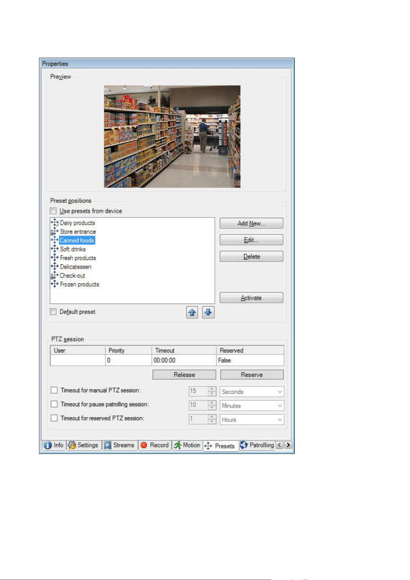
Administrator manual | XProtect® VMS 2023 R1
430 | User interface details

Tasks on the Presets tab
Name Description
New
Add a preset position for a camera in the system:
Add a preset position (type 1)
Use presets from
device
Add a preset position for a PTZ cameras on the camera
itself:
Use preset positions from the camera (type 2)
Default preset
Assign one of a PTZ camera's preset positions as the
camera's default preset position:
Assign a camera's default preset position as default
Edit
Edit an existing preset position defined in the system:
Edit a preset position for a camera (type 1 only)
Edit the name of a preset position defined in the camera:
Rename a preset position for a camera (type 2 only)
Locked
Select this check box to lock a preset position. You can
lock a preset position if you want to prevent users in
XProtect Smart Client or users with limited security
permissions from updating or deleting a preset. Locked
presets are indicated with this icon
.
You lock presets as part of adding (see
Add a preset
position (type 1)) and editing (see Edit a preset position
(type 1 only)).
Activate
Click this button to test a cameras preset position:
Test a preset position (type 1 only).
Reserve and
Release
Prevent other users from taking control over the camera
and release the reservation.
Administrators with security permissions to run a
Administrator manual | XProtect® VMS 2023 R1
431 | User interface details

Name Description
reserved PTZ session can run the PTZ camera in this
mode. This prevents other users from taking control over
the camera. With sufficient permissions, you can release
other users' reserved PTZ sessions:
Reserve and release PTZ sessions.
PTZ session
Monitor if the system is currently patrolling or a user has
taken control:
PTZ session properties on page 432.
View the status of PTZ cameras and manage timeouts for
cameras:
Specify PTZ session timeouts.
PTZ session properties
The PTZ session table shows the current status of the PTZ camera.
Name Description
User
Displays the user that has pressed the Reserved button and currently controls the PTZ
camera.
If a patrolling session is activated by the system, it displays Patrolling.
Priority
Displays the user's PTZ priority. You can only take over PTZ sessions from users with a
lower priority than you.
Timeout Displays the remaining time of the current PTZ session.
Reserved
Indicates if the current session is a reserved PTZ session or not:
l
True: Reserved
l
False: Not reserved
Administrator manual | XProtect® VMS 2023 R1
432 | User interface details

The check boxes in the PTZ session section enable you to change the following timeouts for each PTZ camera.
Name Description
Timeout for
manual PTZ
session
Specify the timeout period for manual PTZ sessions on this
camera if you want the timeout to be different from the default
period. You specify the default period in the Tools menu under
Options.
Timeout for
pause
patrolling
PTZ session
Specify the timeout period for pause patrolling PTZ sessions on
this camera if you want the timeout to be different from the
default period. You specify the default period in the Tools menu
under Options.
Timeout for
reserved PTZ
session
Specify the timeout period for reserved PTZ sessions on this
camera if you want the timeout to be different from the default
period. You specify the default period in the Tools menu under
Options.
Patrolling tab (devices)
The following devices have a Patrolling tab:
l
PTZ cameras
On the Patrolling tab, you can create patrolling profiles - the automatic movement of a PTZ (pan-tilt-zoom)
camera between a number of preset positions.
Before you can work with patrolling, you must specify at least two preset positions for the camera in the
Presets tab, see Add a preset position (type 1).
Patrolling tab, displaying a patrolling profile with customized transitions:
Administrator manual | XProtect® VMS 2023 R1
433 | User interface details
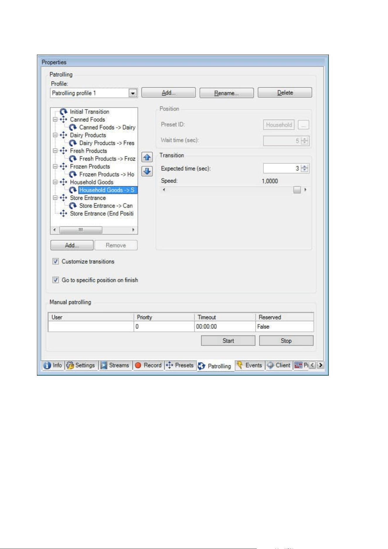
Administrator manual | XProtect® VMS 2023 R1
434 | User interface details
Tasks on the Patrolling tab
Name Description
Add Add a patrolling profile
Preset ID Specify preset positions in a patrolling profile
Wait time
(sec)
Specify the time at each preset position
Customize
transitions
Customize transitions (PTZ)
Go to specific
position on
finish
Specify an end position when patrolling
Manual
patrolling
Monitor if the system is currently patrolling or a user has taken control.
Start and Stop
Use the Start and Stop buttons to initiate and stop manual patrolling.
See Specify PTZ session timeouts for information about how to specify how much time
should pass before regular patrolling is resumed for all or for individual PTZ cameras.
Manual patrolling properties
The Manual patrolling table shows the current status of the PTZ camera.
Name Description
User
Displays the user who has either reserved the PTZ session or started a manual patrolling
and currently controls the camera.
If a patrolling session is activated by the system, it displays Patrolling.
Administrator manual | XProtect® VMS 2023 R1
435 | User interface details
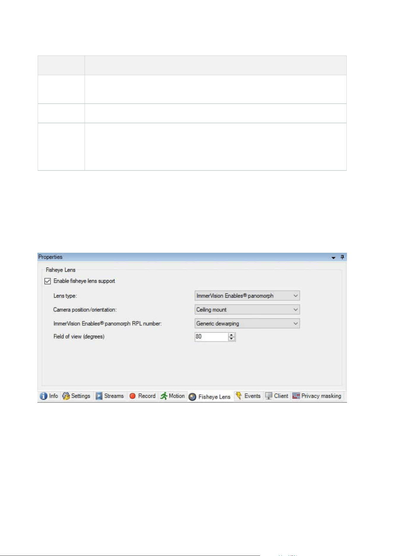
Name Description
Priority
Displays the user's PTZ priority. You can only take over PTZ sessions from users or
patrolling profiles with a lower priority than yours.
Timeout Displays the remaining time of the current reserved or manual PTZ sessions.
Reserved
Indicates if the current session is a reserved PTZ session or not.
l
True: Reserved
l
False: Not reserved
Fisheye lens tab (devices)
The following devices have a Fisheye Lens tab:
l
Fixed cameras with a fisheye lens
On the Fisheye Lens tab, you can enable and configure fisheye lens support for the selected camera.
Task on the Fisheye lens tab
Administrator manual | XProtect® VMS 2023 R1
436 | User interface details
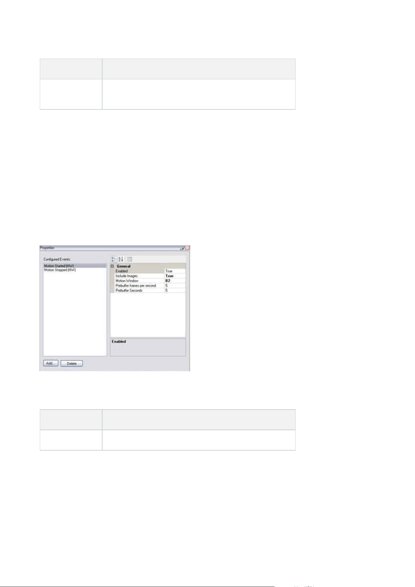
Name Description
Enable fisheye
lens support
Enable and disable fisheye lens support
Events tab (devices)
The following devices have an Events tab:
l
Cameras
l
Microphones
l
Inputs
In addition to the system's event, some devices can be configured to trigger events. You can use these events
when creating event-based rules in the system. Technically, they occur on the actual hardware/device rather
than on the surveillance system.
Tasks on the Events tab
Name Description
Add and Delete Add or delete an event for a device
Administrator manual | XProtect® VMS 2023 R1
437 | User interface details
Event tab (properties)
Name Description
Configured
events
Which events you may select and add in the Configured events list is determined
entirely by the device and its configuration. For some types of devices, the list is empty.
General
The list of properties depends on the device and the event. In order for the event to
work as intended, you must specify some or all of the properties identically on the
device as well as on this tab.
Client tab (devices)
The following devices have a Client tab:
l
Cameras
On the Client tab you can specify which other devices are viewed and heard when you use the camera in
XProtect Smart Client.
The related devices also record when the camera records, see Enable recording on related devices on page 220.
You can also enable Live multicast on the camera. It means that the camera multicasts live streams to the
clients via the recording server.
Multicast streams are not encrypted, even if the recording server uses encryption.
Administrator manual | XProtect® VMS 2023 R1
438 | User interface details
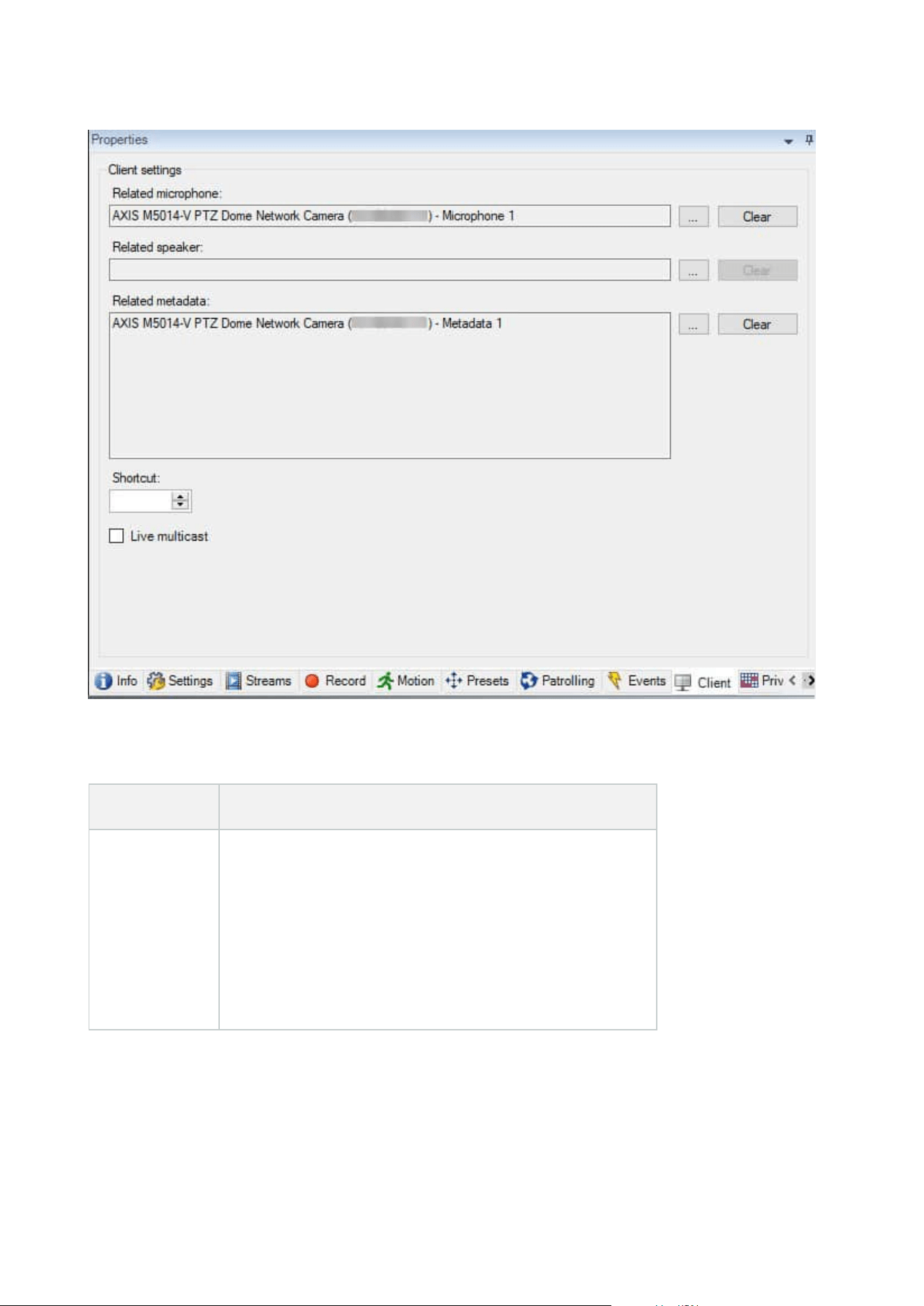
Client tab properties
Name Description
Related
microphone
Specify the microphone on the camera that XProtect Smart
Client users by default listen to audio. The XProtect Smart
Client user can manually select to listen to another
microphone if needed.
Specify the microphone that is related to the video push
camera for streaming video with audio.
The related microphones record when the camera records.
Administrator manual | XProtect® VMS 2023 R1
439 | User interface details
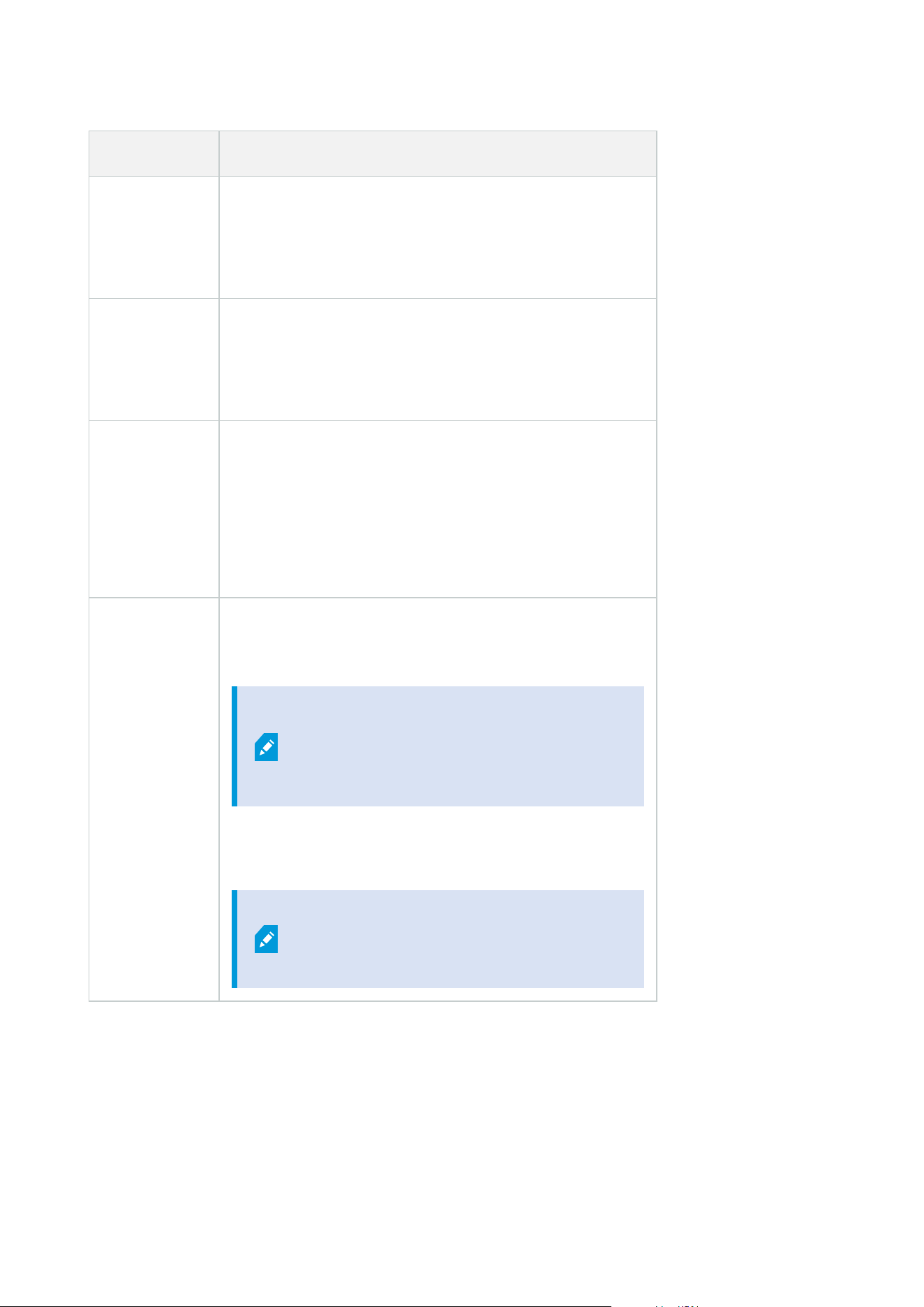
Name Description
Related
speaker
Specify through which speakers on the camera, that XProtect
Smart Client users speak by default. The XProtect Smart Client
user can manually select another speaker if needed.
The related speakers record when the camera records.
Related
metadata
Specify one or more metadata devices on the camera, that
XProtect Smart Client users receive data from.
The related metadata devices record when the camera
records.
Shortcut
To ease the selection of cameras for the XProtect Smart Client
users, define keyboard shortcuts to the camera.
l
Create each shortcut so it uniquely identifies the
camera
l
A camera shortcut number cannot be longer than four
digits
Live multicast
The system supports multicast of live streams from the
recording server to XProtect Smart Client. To enable multicast
of live streams from the camera, select the check box.
Live multicasting only works on the
stream that you have specified as the
camera's default stream on the Streams
tab.
You must also configure multicasting for the recording server.
See Enable multicasting for the recording server on page 197.
Multicast streams are not encrypted,
even if the recording server uses
encryption.
Administrator manual | XProtect® VMS 2023 R1
440 | User interface details
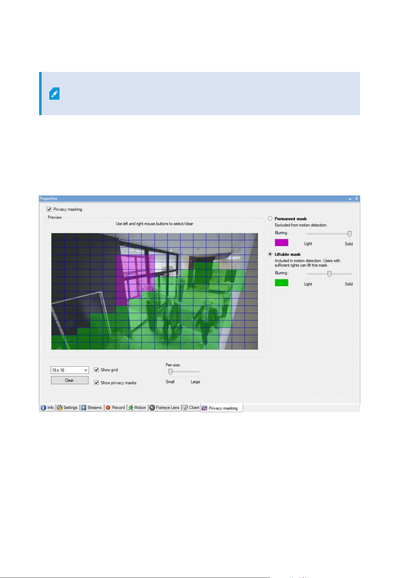
Privacy masking tab (devices)
Available functionality depends on the system you are using. See the complete feature
list, which is available on the product overview page on the Milestone website
(https://www.milestonesys.com/solutions/platform/product-index/).
XProtect Essential+ 2018 R1 and onwards does not support privacy masking, so if you upgrade from a system
with privacy masks applied, the masks will be removed.
The following devices have a Privacy masking tab:
l
Cameras
On the Privacy masking tab, you can enable and configure privacy protection for the selected camera.
Administrator manual | XProtect® VMS 2023 R1
441 | User interface details

Tasks on the Privacy masking tab
Name Description
Privacy masking
Enable/disable privacy masking
Privacy masking (explained)
Permanent
mask and
Liftable mask
Define, if you want a permanent or liftable privacy mask:
Define privacy masks
Tasks related to Privacy masking
Task Description
Change the timeout for lifted privacy masks for the
Smart Client profile associated with the role that has
the permission to lift privacy masks.
Change the timeout for lifted privacy masks
Enable or disable the permission to lift privacy masks
for a role.
Give users permission to lift privacy masks
Create a devices report with information about your
cameras' current privacy masking settings.
Create a report of your privacy masking
configuration
Privacy masking tab (properties)
Name Description
Grid size
The selected grid size determines the density of the grid, regardless whether the grid is
visible in the preview or not.
Administrator manual | XProtect® VMS 2023 R1
442 | User interface details

Name Description
Select between the values 8×8, 16×16, 32×32 or 64×64.
Clear Clears all privacy masks you have specified.
Show grid Select the Show grid check box to make the grid visible.
Show privacy
masks
When you select the Show privacy masks check box (default), permanent privacy masks
appear in purple in the preview and liftable privacy masks in green.
Milestone recommends that you keep the Show privacy masks box selected so that you
and your colleagues can see the current privacy protection configuration.
Pen size
Use the Pen size slider to indicate the size of the selections you wish to make when you
click and drag the grid to select regions. Default is set to small, which is equivalent to
one square in the grid.
Permanent
mask
Appears in purple in the preview on this tab and on the Motion tab.
Permanent privacy masks are always visible in XProtect Smart Client and cannot be
lifted. Can be used to cover areas of the video that never requires surveillance, like
public areas, where surveillance is not allowed. Motion detection is excluded from
permanent masks.
You specify the coverage of privacy masks as either solid or some level of blurred. The
coverage settings apply to both live and recorded video.
Liftable mask
Appears in green in the preview on this tab.
Liftable privacy masks can be lifted in XProtect Smart Client by users with sufficient user
permissions. By default, the privacy masks are lifted for 30 minutes, or until the user
apply them again. Be aware that the privacy masks are lifted on video from all the
cameras that the user has access to.
If the XProtect Smart Client user does not have the permission to lift privacy masks, the
system asks for a user with permission to authorize the lift.
You specify the coverage of privacy masks as either solid or a level of blurred. The
coverage settings apply to both live and recorded video.
Blurring
Use the slider to select the blurring level of the privacy masks in the clients or set the
coverage to solid.
Administrator manual | XProtect® VMS 2023 R1
443 | User interface details
Name Description
By default, the coverage of areas with permanent privacy masks are solid
(nontransparent). By default, liftable privacy masks are medium blurred.
You can inform the client users about the appearance of permanent and liftable privacy
masks, so they are able to distinguish.
Hardware Properties window
You have several options for adding hardware to each recording server in your system.
If your hardware is located behind a NAT-enabled router or a firewall, you may need to
specify a different port number and configure the router/firewall so it maps the port and
IP addresses that the hardware uses.
The Add Hardware wizard helps you detect hardware like cameras and video encoders on your network and
add them to the recording servers on your system. The wizard also helps you add remote recording servers for
Milestone Interconnect setups. Only add hardware to one recording server at a time.
Info tab (hardware)
For information about the Info tab for remote servers, see Info tab (remote server) on page 411.
Name Description
Name
Enter a name. The system uses the name whenever the hardware is listed in the system
and in the clients. The name does not have to be unique.
When you rename hardware, the name is changed globally in the Management Client.
Description
Enter a description of the hardware (optional). The description appears in a number of
listings within the system. For example, when moving the mouse pointer over the
hardware name in the Overview pane:
Administrator manual | XProtect® VMS 2023 R1
444 | User interface details
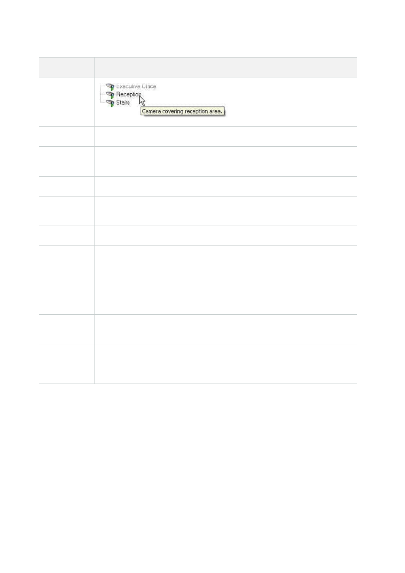
Name Description
Model Identifies the hardware model.
Serial number
Hardware serial number as specified by the manufacturer. The serial number is often,
but not always, identical to the MAC address.
Driver Identifies the driver that handles the connection to the hardware.
IE
Opens the default home page of the hardware vendor. You can use this page for
administration of the hardware.
Address The host name or IP address of the hardware.
MAC address
Specifies the Media Access Control (MAC) address of the system hardware. A MAC
address is a 12-character hexadecimal number uniquely identifying each piece of
hardware on a network.
Firmware
version:
The firmware version of the hardware device. To ensure that the system displays the
current version, run the Update hardware data wizard after every firmware update.
Password last
changed
The Password last changed field shows the time stamp of the latest password change
based on the local time settings of the computer that the password was changed from.
Hardware
data last
updated:
Time and date of the last update of the hardware data.
Settings tab (hardware)
On the Settings tab, you can verify or edit settings for the hardware.
Administrator manual | XProtect® VMS 2023 R1
445 | User interface details
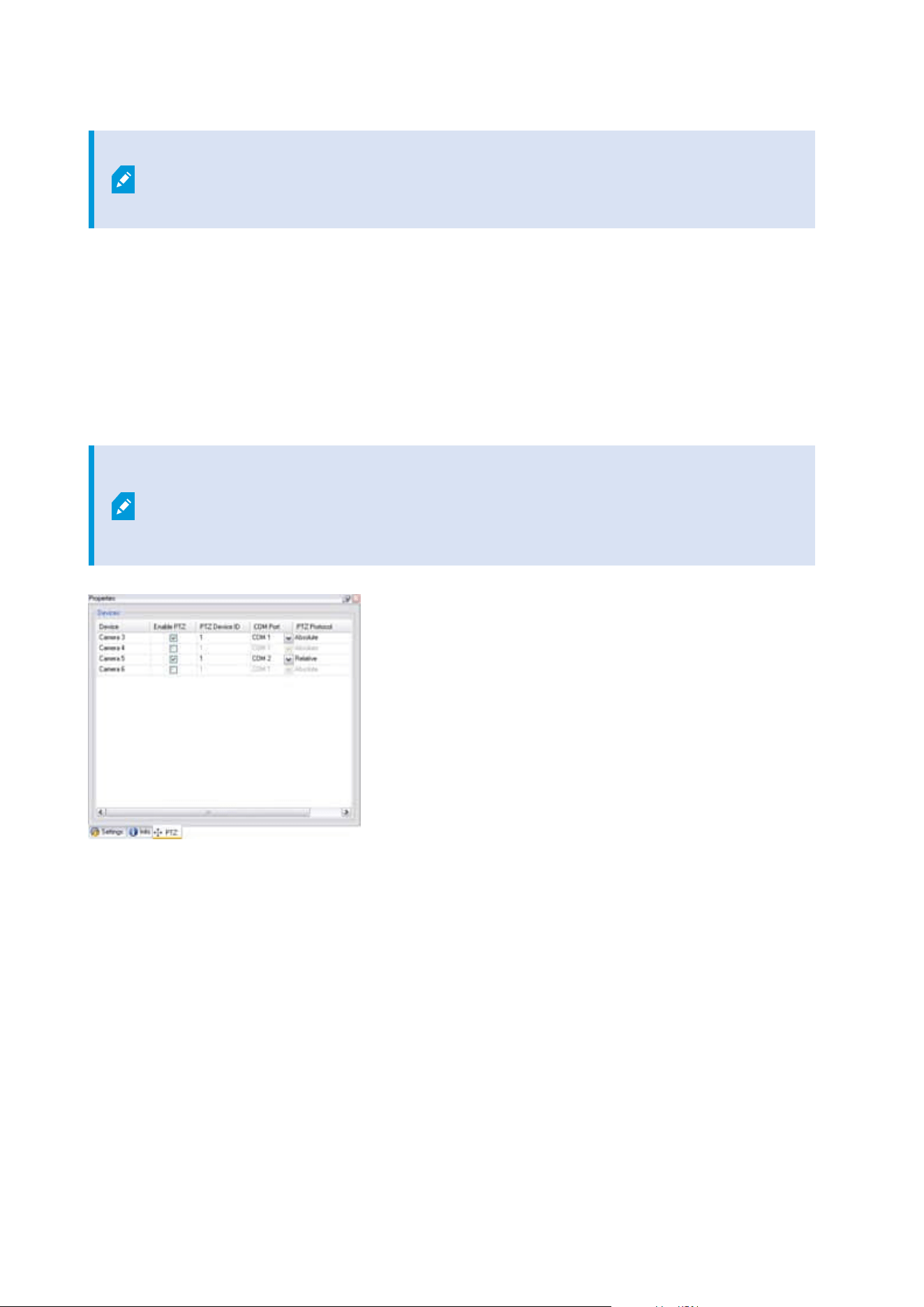
The content of the Settings tab is determined by the selected hardware, and varies
depending on the type of hardware. For some types of hardware, the Settings tab
displays no content at all or read-only content.
For information about the Settings tab for remote servers, see Settings tab (remote server) on page 412.
PTZ tab (video encoders)
On the PTZ tab, you can enable PTZ (pan-tilt-zoom) for video encoders. The tab is available if the selected
device is a video encoder or if the driver supports both non-PTZ and PTZ cameras.
You must enable the use of PTZ separately for each of the video encoder's channels on the PTZ tab before you
can use the PTZ features of the PTZ cameras attached to the video encoder.
Not all video encoders support the use of PTZ cameras. Even video encoders that
support the use of PTZ cameras may require configuration before the PTZ cameras can
be used. It is typically the installation of additional drivers through a browser-based
configuration interface on the device's IP address.
PTZ tab, with PTZ enabled for two channels on a video encoder.
Client node
Clients (node)
This article describes how to customize the user interface for operators in XProtect Smart Client and for system
administrators in the Management Client.
Administrator manual | XProtect® VMS 2023 R1
446 | User interface details
Smart Wall (Client node)
Smart Wall properties
Info tab
On the Info tab for a Smart Wall definition, you can add and edit Smart Wall properties.
Name Description
Name
The name of the Smart Wall definition. Displayed in XProtect Smart Client as the Smart
Wall view group name.
Description
A description of the Smart Wall definition. The description is only used internally in
XProtect Management Client.
Status text Display camera and system status information in camera view items.
No title bar Hide the title bar on all view items on the video wall.
Title bar Show the title bar on all view items on the video wall.
Presets tab
On the Presets tab for a Smart Wall definition, you can add and edit Smart Wall presets
1
.
Name Description
Add New
Add a preset to your Smart Wall definition.
Enter a name and description for the preset.
Edit Edit the name or description of a preset.
1
A predefined layout for one or more Smart Wall monitors in XProtect Smart Client. Presets determine which
cameras are displayed, and how content is structured on each monitor on the video wall.
Administrator manual | XProtect® VMS 2023 R1
447 | User interface details
Name Description
Delete Delete a preset.
Activate
Apply the preset on the Smart Wall monitors that are configured to use the preset. To
apply a preset automatically, you must create a rule that uses the preset.
Layout tab
On the Layout tab for a Smart Wall definition, you position the monitors, so their positions resemble the
mounting of the physical monitors on the video wall. The layout is also used in XProtect Smart Client.
Name Description
Edit Adjust the positioning of the monitors.
Movement
To move a monitor to a new position, select the monitor and drag it to the desired
position, or click one of the arrow buttons to move the monitor in the selected direction.
Zoom buttons
Zoom in or out of the Smart Wall layout preview to ensure you position the monitors
correctly.
Name The name of the monitor. The name is displayed in XProtect Smart Client.
Size The size of the physical monitor on the video wall.
Aspect ratio The height/width relationship of the physical monitor on the video wall.
Monitor properties
Info tab
On the Info tab for a monitor in a Smart Wall preset, you can add monitors and edit the monitor settings.
Administrator manual | XProtect® VMS 2023 R1
448 | User interface details
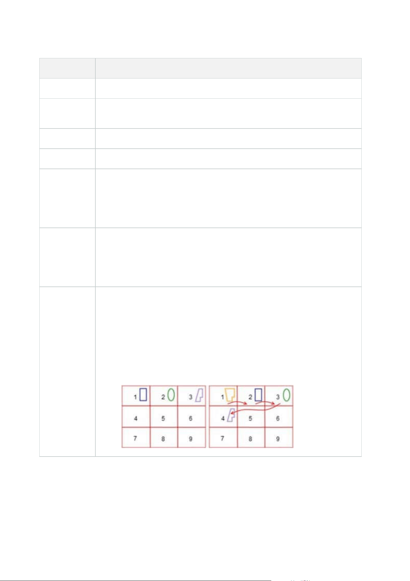
Name Description
Name The name of the monitor. The name is displayed in XProtect Smart Client.
Description
A description of the monitor. The description is only used internally in the XProtect
Management Client.
Size The size of the physical monitor on the video wall.
Aspect ratio The height/width relationship of the physical monitor on the video wall.
Empty preset
Defines what should be displayed on a monitor with an empty preset layout when a
new Smart Wall preset is triggered or selected in XProtect Smart Client:
l
Select Preserve to keep the current content on the monitor.
l
Select Clear to clear all content so nothing is displayed on the monitor.
Empty preset
item
Defines what should be displayed in an empty preset item when a new Smart Wall
preset is triggered or selected in XProtect Smart Client:
l
Select Preserve to keep the current content in the layout item.
l
Select Clear to clear the content so nothing is displayed in the layout item.
Element
insertion
Defines how cameras are inserted in the monitor layout when viewed in the XProtect
Smart Client:
l
Independent - only the content of the affected layout item changes, the rest of
the content in the layout remain the same.
l
Linked - the contents of the layout items are pushed from left to right. If, for
example, a camera is inserted in position 1, the previous camera of position 1 is
pushed to position 2, the previous camera of position 2 is pushed to position 3,
and so on. llustrated in this example:
Administrator manual | XProtect® VMS 2023 R1
449 | User interface details
Presets tab
On the Presets tab for a monitor in a Smart Wall preset, you can edit the view layout and content of the
monitor in the selected Smart Wall preset.
Name Description
Preset A list of Smart Wall presets for the selected Smart Wall definition.
Edit
Click Edit to edit the layout and the content of the selected monitor.
Double-click a camera to remove it.
Click Clear to define a new layout or to exclude the monitor in the Smart Wall preset so the
monitor is available for other content not controlled by the Smart Wall preset.
Click
to select the layout you want to use with your monitor, and click OK.
Smart Client Profiles (Client node)
Available functionality depends on the system you are using. See the complete feature
list, which is available on the product overview page on the Milestone website
(https://www.milestonesys.com/solutions/platform/product-index/).
The following tabs allow you to specify the properties of each Smart Client profile. You can lock the settings in
the Management Client if required, so the users of XProtect Smart Client cannot change them.
To manage Smart Client profiles in the system, expand Client and select Smart Client Profiles.
Info tab (Smart Client profiles)
This tab allows you to specify the following properties:
Tab Description
Info
Name and description, priority of existing profiles and an overview of which roles use the
profile.
If a user is a member of more than one role, each with their individual Smart Client profile, the
user gets the Smart Client profile with the highest priority.
Administrator manual | XProtect® VMS 2023 R1
450 | User interface details
General tab (Smart Client profiles)
This tab allows you to specify the following properties:
Tab Description
General
Settings such as show/hide and mini- and maximize menu settings, login/-out, startup,
timeout, info and messaging options, and enabling or disabling of certain tabs in XProtect
Smart Client.
The Camera error messages, Server error messages, and Live video error message
settings let you control if these error messages are displayed as an overlay, as a black
image with overlay, or if they are hidden.
The Live video stopped message is displayed in XProtect Smart Client when the camera
live feed is stopped. For example if the camera has stopped sending images even though
it's connected.
If you Hide the camera error messages, there is a risk that the
operator overlooks that the connection to a camera has been lost.
The Cameras allowed during search setting lets you control how many cameras operators
can add to searches in XProtect Smart Client. Setting a camera limit can help you prevent
overloading the system.
The Online help setting lets you to disable the help system in XProtect Smart Client.
The Video tutorials setting lets you disable the Video tutorials button in XProtect Smart
Client. The button redirects operators to the video tutorials page:
https://www.milestonesys.com/support/help-yourself/video-tutorials/
Advanced tab (Smart Client profiles)
This tab allows you to specify the following properties:
Tab Description
Advanced
Advanced settings such as maximum decoding threads, deinterlacing and time zone
Administrator manual | XProtect® VMS 2023 R1
451 | User interface details
Tab Description
settings.
Maximum decoding threads controls how many decoding threads are used to decode
video streams. It can help improve performance on multi-core computers in live as well
as playback mode. The exact performance improvement depends on the video stream. It
is mainly relevant if using heavily coded high-resolution video streams like H.264/H.265,
for which the performance improvement potential can be significant, and less relevant if
using, for example, JPEG or MPEG-4.
With deinterlacing, you convert video into a non-interlaced format. Interlacing
determines how an image is refreshed on a screen. The image is refreshed by first
scanning the odd lines in the image, then scanning the even lines. This allows a faster
refresh rate because less information is processed during each scan. However,
interlacing may cause flickering, or the changes in half of the image's lines may be
noticeable.
Adaptive streaming enables XProtect Smart Client to automatically select the live video
streams with the best match in resolution to the streams requested by the view item. This
decreases the load on the CPU and the GPU and thereby improves the decoding
capability and performance of the computer. This requires multi-streaming of live video
streams with different resolutions to be configured, see Manage multi-streaming.
Live tab (Smart Client profiles)
This tab allows you to specify the following properties:
Tab Description
Live
Availability of the live mode and other live features, camera playback, camera overlay buttons,
and bounding boxes, and also live-related MIP plug-ins.
Playback tab (Smart Client profiles)
This tab allows you to specify the following properties:
Administrator manual | XProtect® VMS 2023 R1
452 | User interface details

Tab Description
Playback
Availability of the playback mode and other playback features, layout of print reports,
independent playback, bookmarks, and bounding boxes, and also playback-related MIP
plug-ins.
Setup tab (Smart Client profiles)
This tab allows you to specify the following properties:
Tab Description
Setup
Availability of general setup/panes/buttons, setup-related MIP plug-in and permissions to edit
a map and to edit live video buffering.
Export tab (Smart Client profiles)
This tab allows you to specify the following properties:
Tab Description
Export
Paths, privacy masks, video and still image formats and what to include when exporting
these, export formats for XProtect Smart Client – Player and much more.
Timeline tab (Smart Client profiles)
This tab allows you to specify the following properties:
Tab Description
Timeline
Whether to include audio or not, visibility of indication of time and motion, and finally how
to handle playback gaps.
You can also select whether to show additional data or additional markers from other
sources.
Administrator manual | XProtect® VMS 2023 R1
453 | User interface details
Access Control tab (Smart Client profiles)
This tab allows you to specify the following properties:
Tab Description
Access
Control
Select if access request notifications should pop up on the XProtect Smart Client screen
when triggered by events.
Alarm Manager tab (Smart Client profiles)
This tab allows you to specify the following properties:
Tab Description
Alarm
Manager
Specify whether:
l
Desktop notifications for alarms should be displayed on the computers where
XProtect Smart Client is installed. The notifications appear only if XProtect Smart
Client is running - even if minimized
Desktop notifications for alarms appear only when the
alarms have certain priorities, for example Medium or High.
To configure which alarm priorities that trigger notifications,
go to Alarms > Alarm Data Settings > Alarm Data Levels.
For each required alarm priority, select the Enable desktop
notifications check box. See Alarms Data Settings (Alarms
node).
Administrator manual | XProtect® VMS 2023 R1
454 | User interface details
Tab Description
l
Alarms should play sound notifications on the computers where XProtect Smart
Client is installed. The sound notifications play only if XProtect Smart Client is
running - even if minimized
Sound notifications for alarms play only when a sound is
associated with the alarm. To associate sounds with alarms,
go to Alarms > Alarm Data Settings > Alarm Data Levels.
For each required alarm priority, select the sound to be
associated with the alarm. See Alarms Data Settings (Alarms
node).
Smart map tab (Smart Client profiles)
This tab allows you to specify the following properties:
Tab Description
Smart
map
Specify settings for the smart map feature.
You can specify whether:
l
Milestone Map Service is available for use as a geographic background
l
OpenStreetMaps is available for use as a geographic background
l
XProtect Smart Client will automatically create locations when a user adds a custom
overlay to the smart map.
You can also specify how often you want the system to delete data related to smart maps
from your computer. To help XProtect Smart Client display smart map faster, the client saves
map data in the cache on your computer. Over time this might slow down your computer.
Caching does not apply for Google Maps.
If you want to use Bing Maps or Google Maps as geographic backgrounds, enter a Bing Maps
API key, or a Maps Static APIkey from Google.
Administrator manual | XProtect® VMS 2023 R1
455 | User interface details
View Layout tab (Smart Client profiles)
This tab allows you to specify the following properties:
Management Client Profiles (Client node)
Available functionality depends on the system you are using. See the complete feature
list, which is available on the product overview page on the Milestone website
(https://www.milestonesys.com/solutions/platform/product-index/).
Info tab (Management Client Profiles)
On the Info tab, you can set the following for Management Client profiles:
Component Requirement
Name Enter a name for the Management Client profile.
Priority
Use the up and down arrows to set a priority for the Management Client
profile.
Description Enter a description for the profile. This is optional.
Roles using the
Management Client profile
This field shows the roles that you have associated with the Management
Client profile. You cannot edit this.
Profile tab (Management Client Profiles)
Available functionality depends on the system you are using. See the complete feature
list, which is available on the product overview page on the Milestone website
(https://www.milestonesys.com/solutions/platform/product-index/).
On the Profile tab, you can enable or disable the visibility of the following elements from the Management
Client's user interface:
Administrator manual | XProtect® VMS 2023 R1
456 | User interface details

Navigation
In this section, decide if an administrator user associated with the Management Client profile is allowed to see
the various features and functionality located in the Navigation pane.
Navigation
element
Description
Basics
Allows the administrator user associated with the Management Client profile to see
License Information and Site Information.
Remote
Connect
Services
Allows the administrator user associated with the Management Client profile to see Axis
One-click Camera Connection.
Servers
Allows the administrator user associated with the Management Client profile to see
Recording Servers and Failover Servers.
Devices
Allows the administrator user associated with the Management Client profile to see
Cameras, Microphones, Speakers, Metadata, Input and Output.
Client
Allows the administrator user associated with the Management Client profile to see
Smart Wall, View Groups, Smart Client Profiles, Management Client Profiles and
Matrix.
Rules and
Events
Allows the administrator user associated with the Management Client profile to see
Rules, Time Profiles, Notification Profiles, User-defined Events, Analytics Events and
Generic Events.
Security
Allows the administrator user associated with the Management Client profile to see
Roles and Basic Users.
System
Dashboard
Allows the administrator user associated with the Management Client profile to see
System Monitor, System Monitor Thresholds, Evidence Lock, Current Tasks and
Configuration Reports.
Server Logs
Allows the administrator user associated with the Management Client profile to see
system, audit, and rule-triggered logs.
Access
Control
Allows the administrator user associated with the Management Client profile to see
Access Control features, if you have added any access control system integrations or
plug-ins to your system.
Administrator manual | XProtect® VMS 2023 R1
457 | User interface details
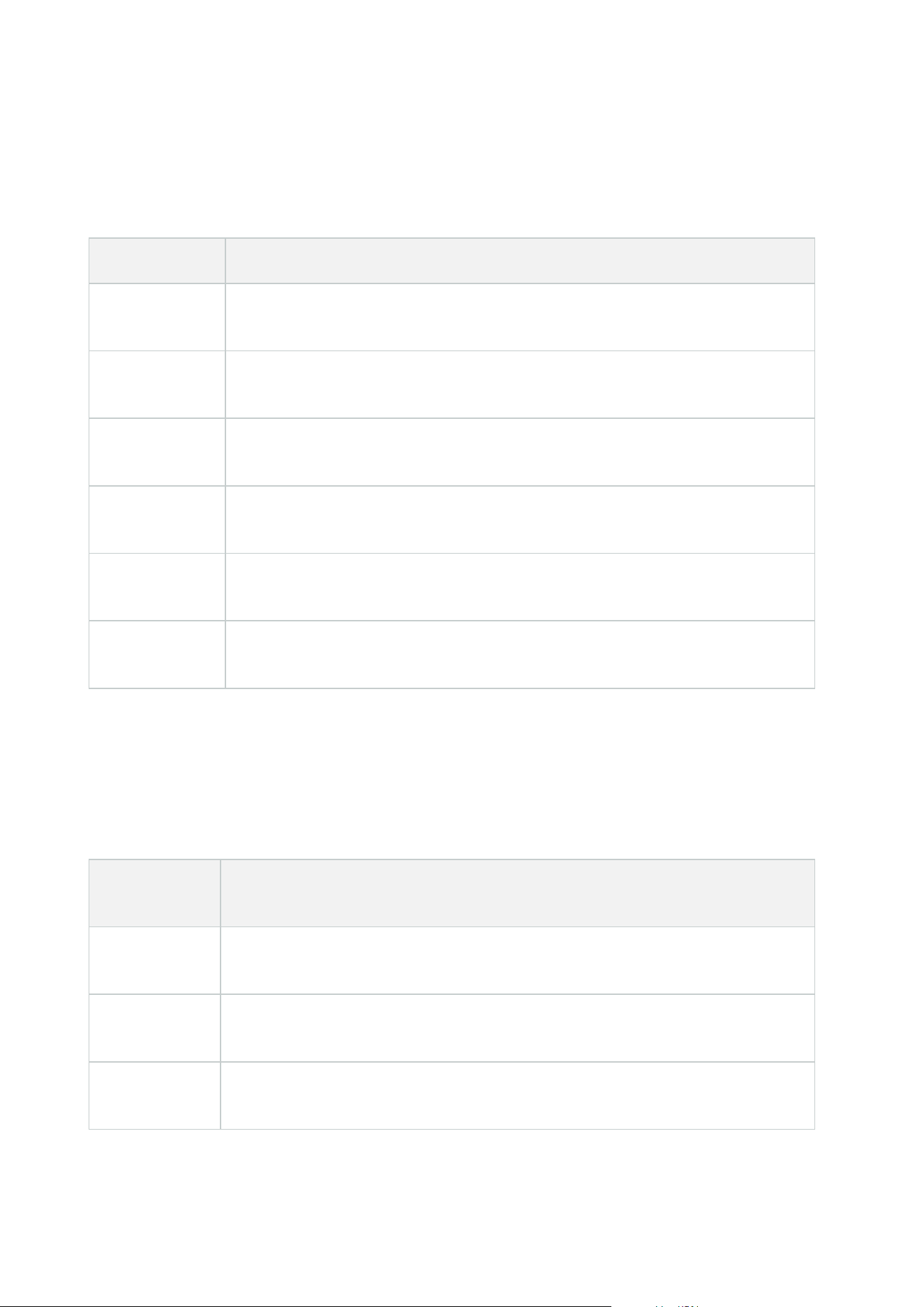
Details
In this section, decide if an administrator user associated with the Management Client profile is allowed to see
the various tabs for a specific device channel, for example the Settings tab or Record tab for cameras.
Device channel Description
Cameras
Allows the administrator user associated with the Management Client profile to see
some or all camera-related settings and tabs.
Microphones
Allows the administrator user associated with the Management Client profile to see
some or all microphone-related settings and tabs.
Speakers
Allows the administrator user associated with the Management Client profile to see
some or all speaker-related settings and tabs.
Metadata
Allows the administrator user associated with the Management Client profile to see
some or all metadata-related settings and tabs.
Input
Allows the administrator user associated with the Management Client profile to see
some or all input-related settings and tabs.
Output
Allows the administrator user associated with the Management Client profile to see
some or all output-related settings and tabs.
Tools Menu
In this section, decide if an administrator user associated with the Management Client profile is allowed to see
the elements that are part of the Tools menu.
Tool Menu
option
Description
Registered
Services
Allows the administrator user associated with the Management Client profile to see
Registered Services.
Effective Roles
Allows the administrator user associated with the Management Client profile to see
Effective Roles.
Options
Allows the administrator user associated with the Management Client profile to see
Options.
Administrator manual | XProtect® VMS 2023 R1
458 | User interface details

Federated Sites
In this section, decide if an administrator user associated with the Management Client profile is allowed to see
the Federated Site Hierarchy pane.
Rules and Events node
Rules (Rules and Events node)
Your system includes a number of default rules that you can use for basic features without setting anything up.
You can deactivate or modify the default rules as you need. If you modify or deactivate the default rules, your
system may not work as desired nor guarantee that video feeds or audio feeds are automatically fed to the
system.
Default rule Description
Go to Preset
when PTZ is
done
Ensures that PTZ cameras go to their respective default preset positions after you have
operated them manually. This rule is not enabled by default.
Even when you have enabled the rule, you must have defined default preset positions
for the relevant PTZ cameras in order for the rule to work. You do this on the Presets
tab.
Play Audio on
Request
Ensures that video is recorded automatically when an external request occurs.
The request is always triggered by a system integrating externally with your system,
and the rule is primarily used by integrators of external systems or plug-ins.
Record on
Bookmark
Ensures that video is recorded automatically when an operator sets a bookmark in
XProtect Smart Client. This is provided you have enabled recording for the relevant
cameras. Recording is enabled by default.
The default recording time for this rule is three seconds before the bookmark is set and
30 seconds after the bookmark is set. You can edit the default recording times in the
rule. The pre-buffer which you set on the Record Tab must match or be longer than the
pre-recording time.
Record on
Motion
Ensures that as long as motion is detected in video from cameras, the video is
recorded, provided recording is enabled for the relevant cameras. Recording is by
default enabled.
While the default rule specifies recording based on detected motion, it does not
Administrator manual | XProtect® VMS 2023 R1
459 | User interface details

Default rule Description
guarantee that the system records video, as you may have disabled individual cameras'
recording for one or more cameras. Even when you have enabled recording,
remember that the quality of recordings may be affected by individual camera's
recording settings.
Record on
Request
Ensures that video is recorded automatically when an external request occurs,
provided recording is enabled for the relevant cameras. Recording is enabled by
default.
The request is always triggered by a system integrating externally with your system,
and the rule is primarily used by integrators of external systems or plug-ins.
Start Audio
Feed
Ensures that audio feeds from all connected microphones and speakers are
automatically fed to the system.
While the default rule enables access to connected microphones' and speakers' audio
feeds immediately upon installing the system, it does not guarantee that audio is
recorded, as you must specify recording settings separately.
Start Feed
Ensures that video feeds from all connected cameras are automatically fed to the
system.
While the default rule enables access to connected cameras' video feeds immediately
upon installing the system, it does not guarantee that video is recorded, as cameras'
recording settings must be specified separately.
Start Metadata
Feed
Ensures that data feeds from all connected cameras are automatically fed to the
system.
While the default rule enables access to connected cameras' data feeds immediately
upon installing the system, it does not guarantee that data is recorded, as cameras'
recording settings must be specified separately.
Show Access
Request
Notification
Ensures that all access control events categorized as 'Access Request', will cause an
access request notification to pop up in XProtect Smart Client, unless the notification
function is disabled in the Smart Client profile.
Recreate default rules
If you accidentally delete any of the default rules, you can recreate them by entering the following content:
Administrator manual | XProtect® VMS 2023 R1
460 | User interface details

Default rule Text to enter
Goto preset
when PTZ is
done
Perform an action on PTZ Manual Session Stopped from All Cameras
Move immediately to default preset on the device on which event occurred
Play Audio on
Request
Perform an action on Request Play Audio Message from External
Play audio message from metadata on the devices from metadata with priority 1
Record on
Bookmark
Perform an action on Bookmark Reference Requested from All Cameras, All
Microphones, All Speakers start recording three seconds before on the device on which
event occurred
Perform action 30 seconds after stop recording immediately
Record on
Motion
Perform an action on Motion Started from All Cameras start recording three seconds
before on the device on which event occurred
Perform stop action on Motion Stopped from All Cameras stop recording three seconds
after
Record on
Request
Perform an action on Request Start Recording from External start recording
immediately on the devices from metadata
Perform stop action on Request Stop Recording from External stop recording
immediately
Start Audio
Feed
Perform an action in a time interval always start feed on All Microphones, All Speakers
Perform an action when time interval ends stop feed immediately
Start Feed
Perform an action in a time interval always start feed on All Cameras
Perform an action when time interval ends stop feed immediately
Start Metadata
Feed
Perform an action in a time interval always start feed on All Metadata
Perform an action when time interval ends stop feed immediately
Show Access
Request
Notification
Perform an action on Access request (Access Control Categories) from Systems [+ units]
Show built-in access request notification
Administrator manual | XProtect® VMS 2023 R1
461 | User interface details

Notification Profiles (Rules and Events node)
Specify the following properties for notification profiles:
Component Requirement
Name
Enter a descriptive name for the notification profile. The name appears later whenever
you select the notification profile during the process of creating a rule.
Description
(optional)
Enter a description of the notification profile. The description appears when you pause
your mouse pointer over the notification profile in the Overview pane's Notification
Profiles list.
Recipients
Enter the e-mail addresses to which the notification profile's e-mail notifications should
be sent. To enter more than one e-mail address, separate addresses with a semicolon.
Subject
Enter the text you want to appear as the subject of the e-mail notification.
You can insert system variables, such as Device name, in the subject and message text
field. To insert variables, click the required variable links in the box below the field.
Message text
Enter the text you want to appear in the body of the e-mail notifications. In addition to
the message text, the body of each e-mail notification automatically contains this
information:
l
What triggered the e-mail notification
l
The source of any attached still images or AVI video clips
Time between
e-mails
Specify required minimum time (in seconds) to pass between the sending of each e-
mail notification. Examples:
l
If specifying a value of 120, a minimum of 2 minutes pass between the sending
of each e-mail notification, even if the notification profile is triggered again by a
rule before the 2 minutes have passed
l
If specifying a value of 0, e-mail notifications is sent each time the notification
profile is triggered by a rule. This can potentially result in a very large number of
e-mail notifications being sent. If using the value 0, you should therefore
carefully consider whether you want to use the notification profile in rules which
are likely to be triggered frequently
Administrator manual | XProtect® VMS 2023 R1
462 | User interface details

Component Requirement
Number of
images
Specify the maximum number of still images you want to include in each of the
notification profile's e-mail notifications. Default is five images.
Time between
images (ms)
Specify the number of milliseconds you want between the recordings presented on the
included images. Example: With the default value of 500 milliseconds, the included
images show recordings with half a second between them.
Time before
event (sec.)
This setting is used to specify the start of the AVI file. By default, the AVI file contains
recordings from 2 seconds before the notification profile is triggered. You can change
this to the number of seconds you require.
Time after
event (sec.)
This setting is used to specify the end of the AVI file. By default, the AVI file ends 4
seconds after the notification profile is triggered. You can change this to the number of
seconds you require.
Frame rate
Specify the number of frames per second you want the AVI file to contain. Default is five
frames per second. The higher the frame rate, the higher the image quality and AVI file
size.
Embed images
in e-mail
If selected (default), images are inserted in the body of e-mail notifications. If not,
images are included in e-mail notifications as attached files.
Events overview
When you add an event-based rule in the Manage Rule wizard, you can select between a number of different
event types. In order for you to get a good overview, events you can select are listed in groups according to
whether they are:
Hardware:
Some hardware can create events themselves, for example to detect motion. You can use these as events but
you must configure them on the hardware before you can use them in the system. You may only be able to use
the events listed on some hardware as not all types of cameras can detect tampering or temperature changes.
Hardware - Configurable events:
Configurable events from hardware are automatically imported from device drivers. This means that they vary
from hardware to hardware and are not documented here. Configurable events are not triggered until you
have added them to the system and configured them on the Event tab for hardware. Some of the configurable
events also require that you configure the camera (hardware) itself.
Administrator manual | XProtect® VMS 2023 R1
463 | User interface details
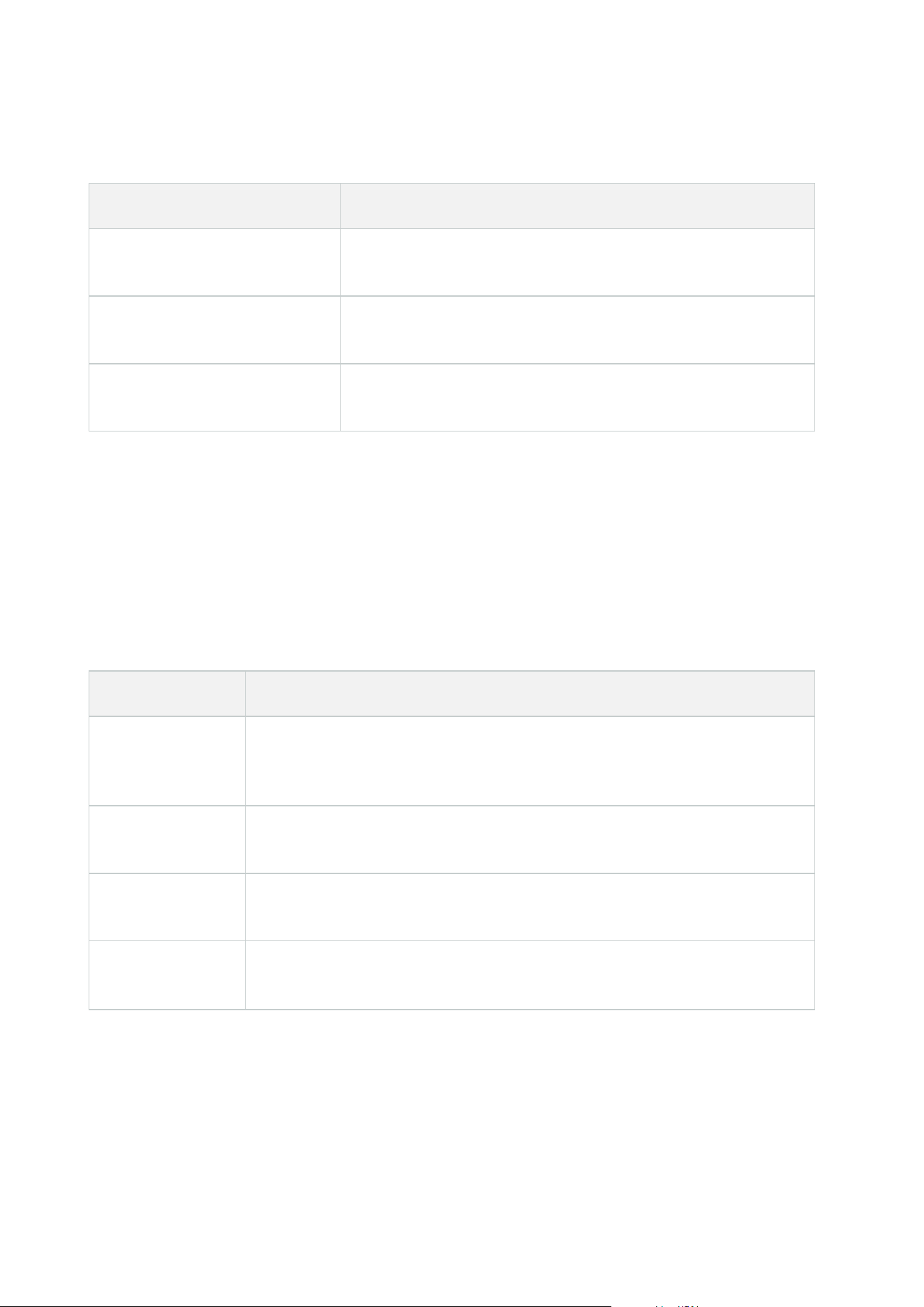
Hardware - Predefined events:
Event Description
Communication Error
(Hardware)
Occurs when a connection to the hardware is lost.
Communication Started
(Hardware)
Occurs when communication with the hardware is successfully
established.
Communication Stopped
(Hardware)
Occurs when communication with the hardware is successfully
stopped.
Devices - Configurable events:
Configurable events from devices are automatically imported from device drivers. This means that they vary
from device to device and are not documented here. Configurable events are not triggered until you have
added them to the system and configured them on the Event tab on a device.
Devices - Predefined events:
Event Description
Bookmark
Reference
Requested
Occurs when a bookmark is made in live mode in the clients. Also, a requirement
for using the Default record on bookmark rule.
Communication
Error (Device)
Occurs when a connection to a device is lost, or when an attempt is made to
communicate with a device, and the attempt is unsuccessful.
Communication
Started (Device)
Occurs when communication with a device is successfully established.
Communication
Stopped (Device)
Occurs when communication with a device is successfully stopped.
Administrator manual | XProtect® VMS 2023 R1
464 | User interface details

Event Description
Evidence Lock
Changed
Occurs when an evidence lock is changed for devices by a client user or via the MIP
SDK.
Evidence Locked
Occurs when an evidence lock is created for devices by a client user or via the MIP
SDK.
Evidence Unlocked
Occurs when an evidence lock is removed for devices by a client user or via the MIP
SDK.
Feed Overflow
Started
Feed overflow (media overflow) occurs when a recording server cannot process
received data as quickly as specified in the configuration and therefore is forced to
discard some recordings.
If the server is healthy, feed overflow usually happens because of slow disk writes.
You can resolve this either by reducing the amount of data written, or by
improving the storage system's performance. Reduce the amount of written data
by reducing frame rates, resolution or image quality on your cameras, but this may
degrade recording quality. If you are not interested in that, instead improve your
storage system's performance by installing extra drives to share the load or by
installing faster disks or controllers.
You can use this event to trigger actions that helps you avoid the problem, for
example, to lower the recording frame rate.
Feed Overflow
Stopped
Occurs when feed overflow (see Feed Overflow Started on page 465) ends.
Live Client Feed
Requested
Occurs when client users request a live stream from a device.
The event occurs upon the request even if the client user's request later turns out
to be unsuccessful, for example because the client user does not have the
permissions required for viewing the requested live feed or because the feed is for
some reason stopped.
Live Client Feed
Terminated
Occurs when client users no longer request a live stream from a device.
Manual Recording
Started
Occurs when a client user starts a recording session for a camera.
The event is triggered even if the device is already recording via rule actions.
Administrator manual | XProtect® VMS 2023 R1
465 | User interface details

Event Description
Manual Recording
Stopped
Occurs when a client user stops a recording session for a camera.
If the rule system also has started a recording session it continues recording even
after the manual recording is stopped.
Marked Data
Reference
Requested
Occurs when an evidence lock is made in playback mode in the clients or via the
MIP SDK.
An event is created that you can use in your rules.
Motion Started
Occurs when the system detects motion in video received from cameras.
This type of event requires that the system's motion detection is enabled for the
cameras to which the event is linked.
In addition to the system's motion detection, some cameras can detect motion
themselves and trigger the Motion Started (HW) event, but it depends on the
configuration of the camera hardware and in the system. See also Hardware -
Configurable events: on page 463.
Motion Stopped
Occurs when motion is no longer detected in received video. See also Motion
Started on page 466.
This type of event requires that the system's motion detection is enabled for the
cameras to which the event is linked.
In addition to the system's motion detection, some cameras can detect motion
themselves and trigger the Motion Stopped (HW) event, but it depends on the
configuration of the camera hardware and in the system. See also Hardware -
Configurable events: on page 463.
Output Activated
Occurs when an external output port on a device is activated.
This type of event requires that at least one device on your system supports output
ports.
Output Changed
Occurs when the state of an external output port on a device is changed.
This type of event requires that at least one device on your system supports output
ports.
Output
Deactivated
Occurs when an external output port on a device is deactivated.
Administrator manual | XProtect® VMS 2023 R1
466 | User interface details
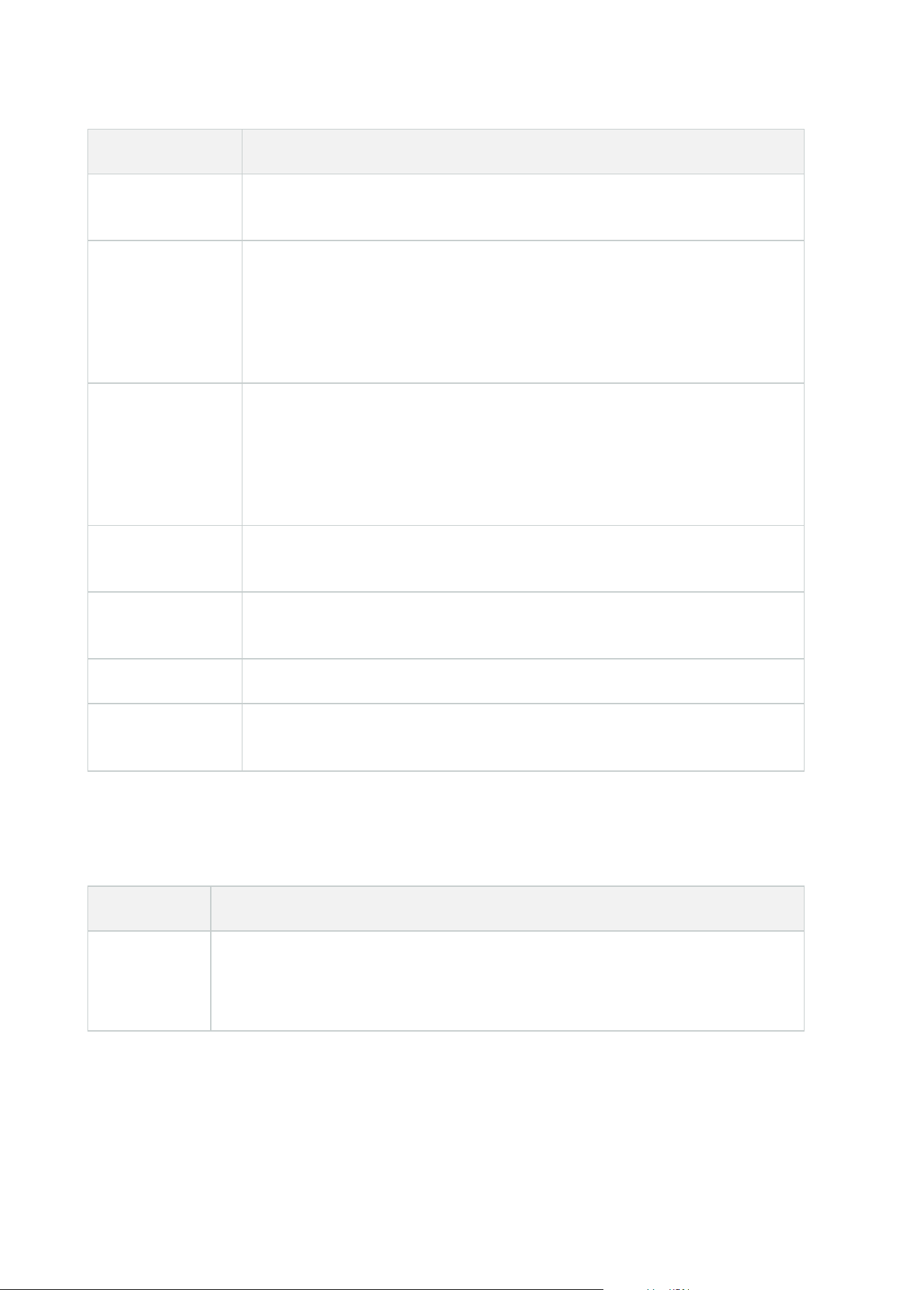
Event Description
This type of event requires that at least one device on your system supports output
ports.
PTZ Manual
Session Started
Occurs when a manually operated PTZ session (as opposed to a PTZ session based
on scheduled patrolling or automatically triggered by an event) is started on a
camera.
This type of event requires that the cameras to which the event is linked are PTZ
cameras.
PTZ Manual
Session Stopped
Occurs when a manually operated PTZ session (as opposed to a PTZ session based
on scheduled patrolling or automatically triggered by an event) is stopped on a
camera.
This type of event requires that the cameras to which the event is linked are PTZ
cameras.
Recording Started
Occurs whenever recording is started. There is a separate event for manual
recording started.
Recording Stopped
Occurs whenever recording is stopped. There is a separate event for manual
recording stopped.
Settings Changed Occurs when settings on a device are successfully changed.
Settings Changed
Error
Occurs when an attempt is made to change settings on a device, and the attempt is
unsuccessful.
External events - Predefined events:
Event Description
Request Play
Audio
Message
Activated when play audio messages are requested via the MIP SDK.
Through the MIP SDK a third-party vendor can develop custom plug-ins (for example,
integration to external access control systems or similar) for your system.
Administrator manual | XProtect® VMS 2023 R1
467 | User interface details

Event Description
Request Start
Recording
Activated when start recordings are requested via the MIP SDK.
Through the MIP SDK a third-party vendor can develop custom plug-ins (for example,
integration to external access control systems or similar) for your system.
Request Stop
Recording
Activated when stop recordings are requested via the MIP SDK.
Through the MIP SDK a third party vendor can develop custom plug-ins (for example,
integration to external access control systems or similar) for your system.
External events - Generic events:
Generic events allow you to trigger actions in the system by sending simple strings via the IP network to the
system. The purpose of generic events is to allow as many external sources as possible to interact with the
system.
External events - User-defined events:
A number of events custom made to suit your system may also be selectable. You can use such user-defined
events for:
l
Making it possible for client users to manually trigger events while viewing live video in the clients
l
Countless other purposes. For example, you may create user-defined events which occur if a particular
type of data is received from a device
See also User-defined events (explained) on page 77.
Recording servers:
Event Description
Archive Available
Occurs when an archive for a recording server becomes available after having
been unavailable. See also Archive Unavailable on page 468.
Archive Unavailable
Occurs when an archive for a recording server becomes unavailable, for
example if the connection to an archive located on a network drive is lost. In
such cases, you cannot archive recordings.
Administrator manual | XProtect® VMS 2023 R1
468 | User interface details

Event Description
You can use the event to, for example, trigger an alarm or a notification profile
so that an email notification is automatically sent to relevant people in your
organization.
Archive Not Finished
Occurs when an archive for a recording server is not finished with the last
archiving round when the next is scheduled to start.
Database Deleting
Recordings Before Set
Retention Size
Occurs when the retention time limit is reached before the database size limit.
Database Deleting
Recordings Before Set
Retention Time
Occurs when database size limit is reached before the retention time limit.
Database Disk Full -
Auto Archiving
Occurs when a database disk is full. A database disk is full when there is less
than 5GB of space is left on the disk:
The oldest data in a database is always auto-archived (or deleted if no next
archive is defined) when less than 5GB of space is free.
Database Disk Full -
Deleting
Occurs when a database disk is full and less than 1GB space is free. Data is
deleted even if a next archive is defined. A database always requires 250MB of
free space. If this limit is reached (if data is not deleted fast enough), no more
data is written to the database until enough space has been freed. The actual
maximum size of your database is the number of gigabytes you specify, minus
5GB.
Database Full - Auto
Archiving
Occurs when an archive for a recording server is full and needs to auto-archive
to an archive in the storage.
Database Repair
Occurs if a database becomes corrupted, in which case the system
automatically attempts two different database repair methods: a fast repair and
a thorough repair.
Database Storage
Available
Occurs when a storage for a recording server becomes available after having
been unavailable. See also Database Storage Unavailable on page 470.
You can, for example, use the event to start recording if it has been stopped by
a Database Storage Unavailable event.
Administrator manual | XProtect® VMS 2023 R1
469 | User interface details
Event Description
Database Storage
Unavailable
Occurs when a storage for a recording server becomes unavailable, for example
if the connection to a storage located on a network drive is lost. In such cases,
you cannot archive recordings.
You can use the event to, for example, stop recording, trigger an alarm or a
notification profile so an e-mail notification is automatically sent to relevant
people in your organization.
Failover encrypted
communication error
Occurs when there is an SSL communication error between the failover server
and monitored recording servers.
Failover Started
Occurs when a failover recording server takes over from a recording server. See
also Failover servers (node).
Failover Stopped
Occurs when a recording server becomes available again and can take over
from a failover recording server.
System monitor events
System monitor events are triggered by exceeded thresholds values configured in the System Monitor
Thresholds node. See also View the current state of your hardware and troubleshoot if needed on page 279.
This functionality requires that the Data Collector service is running.
System Monitor - Server:
Event Description
CPU usage critical Occurs when the CPU usage exceeds the critical CPU threshold.
CPU usage normal Occurs when the CPU usage falls back below the warning CPU threshold.
CPU usage warning
Occurs when the CPU usage exceeds the warning CPU threshold or falls back
below the critical CPU threshold.
Administrator manual | XProtect® VMS 2023 R1
470 | User interface details

Event Description
Memory usage
critical
Occurs when the memory usage exceeds the critical memory threshold.
Memory usage
normal
Occurs when the memory usage falls back below the warning memory
threshold.
Memory usage
warning
Occurs when the memory usage exceeds the warning memory threshold or falls
back below the critical memory usage threshold.
NVIDIA decoding
critical
Occurs when the NVIDIA decoding usage exceeds the critical NVIDIA decoding
threshold.
NVIDIA decoding
normal
Occurs when the NVIDIA decoding usage falls back below the warning NVIDIA
decoding threshold.
NVIDIA decoding
warning
Occurs when the NVIDIA decoding usage exceeds the warning NVIDIA decoding
threshold or falls back below the critical NVIDIA decoding threshold.
NVIDIA memory
critical
Occurs when the NVIDIA memory usage exceeds the critical NVIDIA memory
threshold.
NVIDIA memory
normal
Occurs when the NVIDIA memory usage falls back below the warning NVIDIA
memory threshold.
NVIDIA memory
warning
Occurs when the NVIDIA memory usage exceeds the warning NVIDIA memory
threshold or falls back below the critical NVIDIA memory threshold.
NVIDIA rendering
critical
Occurs when the NVIDIA rendering usage exceeds the critical NVIDIA rendering
threshold.
NVIDIA rendering
normal
Occurs when the NVIDIA rendering usage falls back below the warning NVIDIA
rendering threshold.
NVIDIA rendering
warning
Occurs when the NVIDIA rendering usage exceeds the warning NVIDIA
rendering threshold or falls back below the critical NVIDIA rendering threshold.
Service available
critical
Occurs when a server service stops running.
There are no threshold values for this event.
Administrator manual | XProtect® VMS 2023 R1
471 | User interface details

Event Description
Service available
normal
Occurs when a server service status changes to running.
There are no threshold values for this event.
System Monitor - Camera:
Event Description
Live FPS critical Occurs when the live FPS rate falls below the critical live FPS threshold.
Live FPS normal Occurs when the live FPS rate exceeds the warning live FPS threshold.
Live FPS warning
Occurs when the live FPS rate falls below the warning live FPS threshold or
exceeds the critical live FPS threshold.
Recording FPS critical
Occurs when the recording FPS rate falls below the critical recording FPS
threshold.
Recording FPS
normal
Occurs when the recording FPS rate exceeds the warning recording FPS
threshold.
Recording FPS
warning
Occurs when the recording FPS rate falls below the warning recording FPS
threshold or exceeds the critical recording FPS threshold.
Used space critical
Occurs when the storage used for recordings by a specific camera exceeds the
critical used space threshold.
Used space normal
Occurs when the storage used for recordings by a specific camera falls back
below the warning used space threshold.
Used space warning
Occurs when the storage used for recordings by a specific camera exceeds the
warning used space threshold or falls back below the critical used space
threshold.
Administrator manual | XProtect® VMS 2023 R1
472 | User interface details

System Monitor - Disk:
Event Description
Free space critical Occurs when the disk space usage exceeds the critical free space threshold.
Free space normal Occurs when the disk space usage falls below the warning free space threshold.
Free space warning
Occurs when the disk space usage exceeds the warning free space threshold or
falls back below the critical free space threshold.
System Monitor - Storage:
Event Description
Retention time
critical
Occurs when the system predicts that the storage will be filled up faster than the
critical retention time threshold value. For example, when data from video
streams is filling up the storage faster than expected.
Retention time
normal
Occurs when the system predicts that the storage will be filled up slower than the
warning retention time threshold value. For example, when data from video
streams is filling up the storage at the expected rate.
Retention time
warning
Occurs when the system predicts that the storage will be filled up faster than the
warning retention time threshold value or slower than the critical retention time
threshold value. For example, when data from video streams is filling up the
storage faster than expected due to more motion detected by the cameras
configured to record on motion.
Administrator manual | XProtect® VMS 2023 R1
473 | User interface details
Other:
Event Description
Automatic license activation failed
Occurs when online automatic license activation fails.
There are no thresholds values for this event.
Scheduled password change started Occurs when a scheduled password change starts.
Scheduled password change completed
successfully
Occurs when a scheduled password change completes
without errors.
Scheduled password change completed
with errors
Occurs when a scheduled password change completes
with errors.
Events from add-on products and integrations:
Events from add-on products and integrations can be used in the rule system, for example:
l
Analytics events can also be used in the rule system
Actions and stop actions
A set of actions and stop actions are available for rule creation in the Manage Rule wizard. You may have more
actions available if your system installation uses add-on products or vendor-specific plug-ins. For each type of
action, stop action information is listed if relevant.
Manage Rule Wizard
Action Description
Start recording
on <devices>
Start recording and saving data in the database from the selected devices.
When your select this type of action, the Manage Rule wizard prompts you to
specify:
When recording should start. This happens either immediately or a number of
seconds before the triggering event/beginning of the triggering time interval and on
which devices the action should take place.
Administrator manual | XProtect® VMS 2023 R1
474 | User interface details
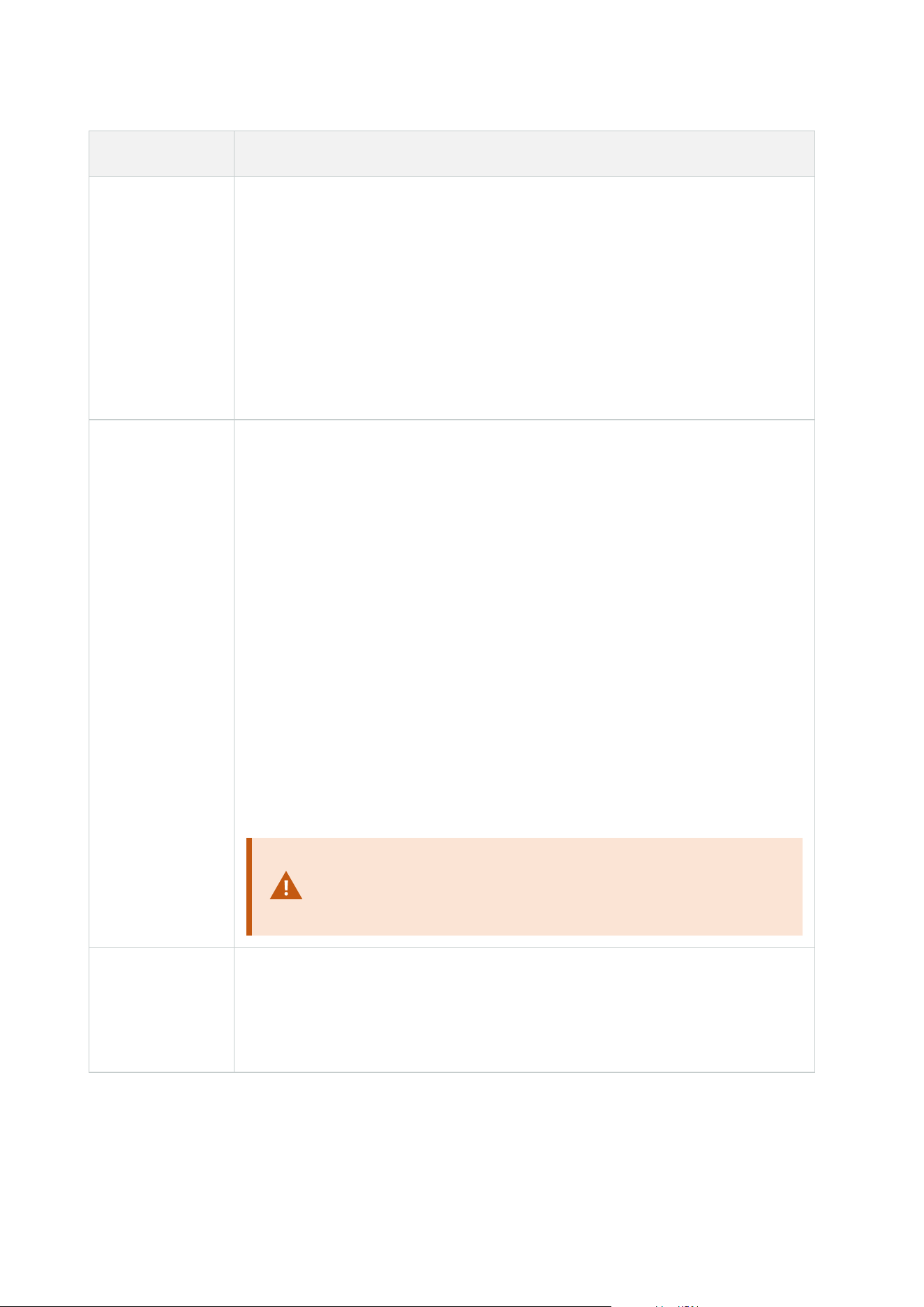
Action Description
This type of action requires that you have enabled recording on the devices to which
the action is linked. You can only save data from before an event or time interval if
you have enabled pre-buffering for the relevant devices. You enable recording and
specify pre-buffering settings for a device on the Record tab.
Stop action required: This type of action requires one or more stop actions. In one
of the following steps, the wizard automatically prompts you to specify the stop
action: Stop recording.
Without this stop action, recording would potentially continue indefinitely. You also
have the option of specifying further stop actions.
Start feed on
<devices>
Begin data feed from devices to the system. When the feed from a device is started,
data is transferred from the device to the system, in which case you may view and
record, depending on the data type.
When you select this type of action, the Manage Rule wizard prompts you to specify
on which devices to start the feeds. Your system includes a default rule which
ensures that feeds are always started on all cameras.
Stop action required: This type of action requires one or more stop actions. In one
of the following steps, the wizard automatically prompts you to specify the stop
action: Stop feed.
You can also specify further stop actions.
Using the mandatory stop action Stop feed to stop the feed from a device means
that data is no longer transferred from the device to the system, in which case live
viewing and recording of video, for example, is no longer possible. However, a
device on which you have stopped the feed can still communicate with the recording
server, and you can start the feed again automatically through a rule, as opposed to
when you manually have disabled the device.
While this type of action enables access to selected devices'
data feeds, it does not guarantee that data is recorded, as you
must specify recording settings separately.
Set <Smart Wall>
to <preset>
Sets the XProtect Smart Wall to a selected preset. Specify the preset on the Smart
Wall Presets tab.
No mandatory stop action: This type of action does not require a stop action.You
can specify optional stop actions to be performed on either an event or after a
Administrator manual | XProtect® VMS 2023 R1
475 | User interface details

Action Description
period of time.
Set <Smart Wall>
<monitor> to
show <cameras>
Sets a specific XProtect Smart Wall monitor to display live video from the selected
cameras on this site or any child site configured in Milestone Federated Architecture.
No mandatory stop action: This type of action does not require a stop action.You
can specify optional stop actions to be performed on either an event or after a
period of time.
Set <Smart Wall>
<monitor> to
show text
<messages>
Sets a specific XProtect Smart Wall monitor to display a user-defined text message of
up to 200 characters.
No mandatory stop action: This type of action does not require a stop action.You
can specify optional stop actions to be performed on either an event or after a
period of time.
Remove
<cameras> from
<Smart Wall>
monitor
<monitor>
Stop displaying video from a specific camera.
No mandatory stop action: This type of action does not require a stop action.You
can specify optional stop actions to be performed on either an event or after a
period of time.
Set live frame
rate on <devices>
Sets a particular frame rate to use when the system displays live video from the
selected cameras that substitutes the cameras' default frame rate. Specify this on
the Settings tab.
When you select this type of action, the Manage Rule wizard prompts you to specify
which frame rate to set, and on which devices. Always verify that the frame rate you
specify is available on the relevant cameras.
Stop action required: This type of action requires one or more stop actions. In one
of the following steps, the wizard automatically prompts you to specify the stop
action: Restore default live frame rate.
Without this stop action, the default frame rate would potentially never be restored.
You also have the option of specifying further stop actions.
Set recording
frame rate on
<devices>
Sets a particular frame rate to use when the system saves recorded video from the
selected cameras in the database, instead of the cameras' default recording frame
rate.
When you select this type of action, the Manage Rule wizard prompts you to specify
Administrator manual | XProtect® VMS 2023 R1
476 | User interface details

Action Description
which recording frame rate to set, and on which cameras.
You can only specify a recording frame rate for JPEG, a video codec with which each
frame is separately compressed into a JPEG image. This type of action also requires
that you have enabled recording on the cameras to which the action is linked. You
enable recording for a camera on the Record tab. The maximum frame rate you can
specify depends on the relevant camera types, and on their selected image
resolution.
Stop action required: This type of action requires one or more stop actions. In one
of the following steps, the wizard automatically prompts you to specify the stop
action: Restore default recording frame rate.
Without this stop action, the default recording frame rate would potentially never be
restored. You also have the option of specifying further stop actions.
Set recording
frame rate to all
frames for MPEG-
4/H.264/H.265 on
<devices>
Sets the frame rate to record all frames when the system saves recorded video from
the selected cameras in the database, instead of keyframes only. Enable the
recording keyframes only function on the Record tab.
When you select this type of action, the Manage Rule wizard prompts you to select
which devices the action should apply for.
You can only enable keyframe recording for MPEG-4/H.264/H.265. This type of action
also requires that you have enabled recording on the cameras to which the action is
linked. You enable recording for a camera on the Record tab.
Stop action required: This type of action requires one or more stop actions. In one
of the following steps, the wizard automatically prompts you to specify the stop
action:
Restore default recording frame rate of keyframes for MPEG-4/H.264/H.265
Without this stop action, the default setting would potentially never be restored. You
also have the option of specifying further stop actions.
Start patrolling
on <device>
using <profile>
with PTZ priority
<priority>
Begins PTZ patrolling according to a particular patrolling profile for a particular PTZ
camera with a particular priority. This is an exact definition of how patrolling should
be carried out, including the sequence of preset positions, timing settings, and
more.
If you have upgraded your system from an older version of the system, the old
values (Very Low, Low, Medium, High and Very High) have been translated as
follows:
Administrator manual | XProtect® VMS 2023 R1
477 | User interface details
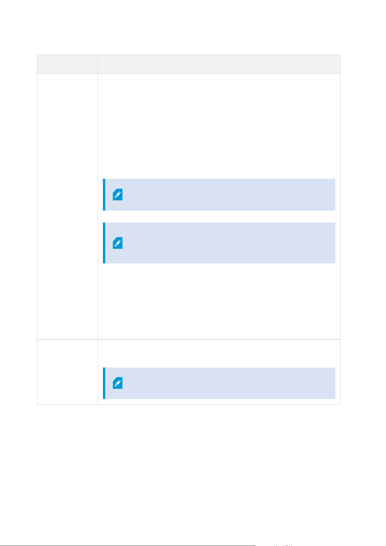
Action Description
l
Very Low = 1000
l
Low = 2000
l
Medium = 3000
l
High = 4000
l
Very High = 5000
When you select this type of action, the Manage Rule wizard prompts you to select a
patrolling profile. You can only select one patrolling profile on one device and you
cannot select several patrolling profiles.
This type of action requires that the devices to which the
action is linked are PTZ devices.
You must define at least one patrolling profile for the device
(s). You define patrolling profiles for a PTZ camera on the
Patrolling tab.
Stop action required: This type of action requires one or more stop actions. In one
of the following steps, the wizard automatically prompts you to specify the stop
action:
Stop patrolling
Without this stop action, patrolling would potentially never stop. You can also specify
further stop actions.
Pause patrolling
on <devices>
Pauses PTZ patrolling. When you select this type of action, the Manage Rule wizard
prompts you to specify the devices on which to pause patrolling.
This type of action requires that the devices to which the
action is linked are PTZ devices.
Administrator manual | XProtect® VMS 2023 R1
478 | User interface details
Action Description
You must define at least one patrolling profile for the device
(s). You define patrolling profiles for a PTZ camera on the
Patrolling tab.
Stop action required: This type of action requires one or more stop actions. In one
of the following steps, the wizard automatically prompts you to specify the stop
action: Resume patrolling
Without this stop action, patrolling would potentially pause indefinitely. You have
also the option of specifying further stop actions.
Move <device> to
<preset> position
with PTZ priority
<priority>
Moves a particular camera to a particular preset position - however always according
to priority. When selecting this type of action, the Manage Rule wizard prompts you
to select a preset position. Only one preset position on one camera can be selected.
It is not possible to select several preset positions.
This type of action requires that the devices to which the
action is linked are PTZ devices.
This action requires that you have defined at least one preset
position for those devices. You define preset positions for a
PTZ camera on the Presets tab.
No mandatory stop action: This type of action does not require a stop action.You
can specify optional stop actions to be performed on either an event or after a
period of time.
Move to default
preset on
<devices> with
PTZ priority
<priority>
Moves one or more particular cameras to their respective default preset positions -
however always according to priority. When you select this type of action, the
Manage Rule wizard prompts you to select which devices the action should apply
for.
Administrator manual | XProtect® VMS 2023 R1
479 | User interface details

Action Description
This type of action requires that the devices to which the
action is linked are PTZ devices.
This action requires that you have defined at least one preset
position for those devices. You define preset positions for a
PTZ camera on the Presets tab.
No mandatory stop action: This type of action does not require a stop action.You
can specify optional stop actions to be performed on either an event or after a
period of time.
Set device output
to <state>
Sets an output on a device to a particular state (activated or deactivated). When you
select this type of action, the Manage Rule wizard prompts you to specify which
state to set, and on which devices.
This type of action requires that the devices to which the action is linked each have at
least one external output unit connected to an output port.
No mandatory stop action: This type of action does not require a stop action.You
can specify optional stop actions to be performed on either an event or after a
period of time.
Create bookmark
on <device>
Creates a bookmark on live streaming or recordings from a selected device. A
bookmark makes it easy to retrace a certain event or period in time. Bookmark
settings are controlled from the Options dialog box. When you select this type of
action, the Manage Rule wizard prompts you to specify bookmark details and select
devices.
No mandatory stop action: This type of action does not require a stop action.You
can specify optional stop actions to be performed on either an event or after a
period of time.
Play audio
<message> on
<devices> with
<priority>
Plays back an audio message on selected devices triggered by an event. Devices are
mostly speakers or cameras.
This type of action requires that you have uploaded the message to the system on
Tools > Options > Audio messages tab.
You can create more rules to the same event and send different messages to each
device, but always according to priority. The priorities that control the sequence are
those set on the rule and on the device for a role on the Speech tab:
Administrator manual | XProtect® VMS 2023 R1
480 | User interface details

Action Description
l
If a message is played back and another message with the same priority is
sent to the same speaker, the first message will complete and then the
second one starts
l
If a message is played back and another message with a higher priority is
sent to the same speaker, the first message is interrupted and the second
one starts immediately
Send notification
to <profile>
Sends a notification, using a particular notification profile. When you select this type
of action, the Manage Rule wizard prompts you to select a notification profile, and
which devices to include pre-alarm images from. You can only select one notification
profile and you cannot select several notification profiles. A single notification profile
may contain several recipients.
You can also create more rules to the same event and send different notifications to
each of the notification profiles. You can copy and re-use the content of rules by
right-clicking a rule in the Rules list.
This type of action requires that you have defined at least one notification profile.
Pre-alarm images are only included if you have enabled the Include images option
for the relevant notification profile.
No mandatory stop action: This type of action does not require a stop action.You
can specify optional stop actions to be performed on either an event or after a
period of time.
Make new <log
entry>
Generates an entry in the rule log. When selecting this type of action, the Manage
Rule wizard prompts you to specify a text for the log entry. When you specify the log
text, you can insert variables, such as $DeviceName$, $EventName$, into the log
message.
No mandatory stop action: This type of action does not require a stop action.You
can specify optional stop actions to be performed on either an event or after a
period of time.
Start plug-in on
<devices>
Starts one or more plug-ins. When you select this type of action, the Manage Rule
wizard prompts you to select required plug-ins, and on which devices to start the
plug-ins.
This type of action requires that you have at least one or more plug-ins installed on
your system.
Administrator manual | XProtect® VMS 2023 R1
481 | User interface details
Action Description
No mandatory stop action: This type of action does not require a stop action.You
can specify optional stop actions to be performed on either an event or after a
period of time.
Stop plug-in on
<devices>
Stops one or more plug-ins. When you select this type of action, the Manage Rule
wizard prompts you to select required plug-ins, and on which devices to stop the
plug-ins.
This type of action requires that you have at least one or more plug-ins installed on
your system.
No mandatory stop action: This type of action does not require a stop action.You
can specify optional stop actions to be performed on either an event or after a
period of time.
Apply new
settings on
<devices>
Changes device settings on one or more devices. When you select this type of action,
the Manage Rule wizard prompts you to select relevant devices, and you can define
the relevant settings on the devices you have specified.
If you define settings for more than one device, you can only
change settings that are available for all of the specified
devices.
Example: You specify that the action should be linked to Device 1 and Device 2.
Device 1 has the settings A, B and C, and Device 2 has the settings B, C and D. In this
case, you can only change the settings that are available for both devices, namely
settings B and C.
No mandatory stop action: This type of action does not require a stop action.You
can specify optional stop actions to be performed on either an event or after a
period of time.
Set Matrix to
view <devices>
Makes video from the selected cameras appear on a computer capable of displaying
Matrix-triggered video such as a computer on which you have installed XProtect
Smart Client.
When you select this type of action, the Manage Rule wizard prompts you to select a
Matrix recipient, and one or more devices from which to display video on the
selected Matrix recipient.
Administrator manual | XProtect® VMS 2023 R1
482 | User interface details
Action Description
This type of action allows you to select only a single Matrix recipient at a time. If you
want to make video from the selected devices appear on more than one Matrix
recipient, you should create a rule for each required Matrix recipient or use the
XProtect Smart Wall feature. By right-clicking a rule in the Rules list, you can copy
and re-use the content of rules. This way, you can avoid having to create near-
identical rules from scratch.
As part of the configuration on the Matrix recipients
themselves, users must specify the port number and
password required for the Matrix communication. Make sure
that the users have access to this information. The users must
typically also define the IP addresses of allowed hosts from
which commands regarding display of Matrix-triggered video
is accepted. In that case, the users must also know the IP
address of the management server, or any router or firewall
used.
Send SNMP trap
Generates a small message which logs events on selected devices. The text of SNMP
traps is auto-generated and cannot be customized. It can contain the source type
and name of the device on which the event occurred.
No mandatory stop action: This type of action does not require a stop action.You
can specify optional stop actions to be performed on either an event or after a
period of time.
Retrieve and
store remote
recordings from
<devices>
Retrieves and stores remote recordings from selected devices (that support edge
recording) in a specified period before and after the triggering event.
This rule is independent of the Automatically retrieve remote recordings when
connection is restored setting.
No mandatory stop action: This type of action does not require a stop action.You
can specify optional stop actions to be performed on either an event or after a
period of time.
Retrieve and
store remote
recordings
between <start
Retrieves and stores remote recordings in a specified period from selected devices
(that support edge recording).
This rule is independent of the Automatically retrieve remote recordings when
connection is restored setting.
Administrator manual | XProtect® VMS 2023 R1
483 | User interface details

Action Description
and end time>
from <devices>
No mandatory stop action: This type of action does not require a stop action.You
can specify optional stop actions to be performed on either an event or after a
period of time.
Save attached
image
Ensures that when an image is received from the Images Received event (sent via
SMTP email from a camera), it is saved for future usage. In future, other events can
possibly also trigger this action.
No mandatory stop action: This type of action does not require a stop action.You
can specify optional stop actions to be performed on either an event or after a
period of time.
Activate
archiving on
<archives>
Starts archiving on one or more archives. When you select this type of action, the
Manage Rule wizard prompts you to select relevant archives.
No mandatory stop action: This type of action does not require a stop action.You
can specify optional stop actions to be performed on either an event or after a
period of time.
On <site> trigger
<user-defined
event>
Relevant mostly within Milestone Federated Architecture, but you can also use this in
a single site setup. Use the rule to trigger a user-defined event on a site, normally a
remote site within a federated hierarchy.
No mandatory stop action: This type of action does not require a stop action.You
can specify optional stop actions to be performed on either an event or after a
period of time.
Show <access
request
notification>
Lets you access request notifications pop up on the XProtect Smart Client screen
when the criteria for the triggering events are met. Milestone recommends that you
use access control events as triggering events for this action, because access request
notifications typically are configured for operating on related access control
commands and cameras.
This type of action requires that you have at least one access control plug-in installed
on your system.
No mandatory stop action: This type of action does not require a stop action.You
can specify optional stop actions to be performed on either an event or after a
period of time.
Set <camera> to
Cameras are assigned to the rule-based DLNA channel based on events. This type of
Administrator manual | XProtect® VMS 2023 R1
484 | User interface details
Action Description
<rule-based
DLNA channel>
action requires that you have a DLNA server installed on your system.
No mandatory stop action: This type of action does not require a stop action.You
can specify optional stop actions to be performed on either an event or after a
period of time.
Remove
<camera> from
<rule-based
DLNA channel>
Cameras are removed from the rule-based DLNA channel based on events. This type
of action requires that you have a DLNA server installed on your system.
No mandatory stop action: This type of action does not require a stop action.You
can specify optional stop actions to be performed on either an event or after a
period of time.
Remove current
camera from
<rule-based
DLNA channel>
The camera with the active stream is removed from the rule-based DLNA channel
based on events. This type of action requires that you have a DLNA server installed
on your system.
No mandatory stop action: This type of action does not require a stop action.You
can specify optional stop actions to be performed on either an event or after a
period of time.
Change the
password on
hardware devices
Changes the password of selected hardware devices to a randomly-generated
password based on the password requirements for that specific hardware device.
For a list of supported hardware devices, see Find hardware.
This action is only available when you set up a rule using the
Perform an action on a <recurring time> rule type.
The following events are available for the action:
l
Scheduled password change started on page 474
l
Scheduled password change completed successfully on page 474
l
Scheduled password change completed with errors on page 474
This type of action does not have a stop action.
You can view the progress of this action in the Current Tasks node. For more
information, seeView currently ongoing tasks on recording servers on page 277.
To view the action results - go to the Server Logs node, on the System logs tab. For
more information, see Server Logs tab (options) on page 369.
For more information, see System logs (tab).
Administrator manual | XProtect® VMS 2023 R1
485 | User interface details
Test Analytics Event (properties)
When you test the requirements of an analytics event, a window appears that checks four conditions and
provides possible error descriptions and solutions.
Condition Description Error messages and solutions
Changes
saved
If the event is new, is it saved?
Or if there are changes to the
event name, are these
changes saved?
Save changes before testing analytics event.
Solution/Explanation: Save changes.
Analytics
Events
enabled
Is the Analytics Event feature
enabled?
Analytics events have not been enabled.
Solution/Explanation: Enable the Analytics Events
feature. To do this, click Tools > Options > Analytics
Events and select the Enabled check box.
Address
allowed
Is the IP address/host name
of the machine sending the
event(s) allowed (listed on the
analytics events address list)?
The local host name must be added as allowed
address for the Analytics Event service.
Solution/Explanation: Add your machine to the
analytics events address list of allowed IP addresses or
host names.
Error resolving the local host name.
Solution/Explanation: The IP address or host name of
the machine cannot be found or is invalid.
Send
analytics
event
Did sending a test event to
the Event Server succeed?
See table below.
Each step is marked by either failed: or successful: .
Error messages and solutions for the condition Send analytics event:
Error message Solution
Event server not
Unable to find the event server on the list of registered services.
Administrator manual | XProtect® VMS 2023 R1
486 | User interface details

Error message Solution
found
Error connecting to
event server
Unable to connect to the event server on the stated port. The error occurs most
likely because of network problems, or the Event Server service has stopped.
Error sending
analytics event
The connection to the event server is established, but the event cannot be sent.
The error most likely occurs because of network problems, for example a time
out.
Error receiving
response from event
server
The event has been sent to the event server, but no reply received. The error
most likely occurs because of network problems or a port that is busy.
See the event server log, typically located at ProgramData\Milestone\XProtect
Event Server\Logs\.
Analytics event
unknown by event
server
The Event Server service does not know the event. The error most likely occurs
because the event or changes to the event have not been saved.
Invalid analytics
event received by
event server
The event format is incorrect.
Sender unauthorized
by event server
Most likely your machine is not on the list of allowed IP addresses or host
names.
Internal error in
event server
Event server error.
See the event server log, typically located at ProgramData\Milestone\XProtect
Event Server\Logs\.
Invalid response
received from Event
server
The response is invalid. Possibly the port is busy or there are network problems.
See the event server log, typically located at ProgramData\Milestone\XProtect
Event Server\Logs\.
Unknown response
from event server
The response is valid, but not understood. The error occurs possibly because of
network problems, or the port is busy.
See the event server log, typically located at ProgramData\Milestone\XProtect
Event Server\Logs\.
Unexpected error Please contact Milestone support for help.
Administrator manual | XProtect® VMS 2023 R1
487 | User interface details

Generic Events and Data sources (properties)
This feature only works if you have the XProtect event server installed.
Generic event (properties)
Component Requirement
Name
Unique name for the generic event. Name must be unique among all types of events,
such as user defined events, analytics events, and so on.
Enabled Generic events are by default enabled. Clear the check box to disable the event.
Expression
Expression that the system should look out for when analyzing data packages. You can
use the following operators:
l
( ): Used to ensure that related terms are processed together as a logical unit.
They can be used to force a certain processing order in the analysis
Example: The search criteria "(User001 OR Door053) AND Sunday" first processes the
two terms inside the parenthesis, then combines the result with the last part of the
string. So, the system first looks for any packages containing either of the terms
User001 or Door053, then takes the results and run through them in order to see
which packages also contain the term Sunday.
l
AND: With an AND operator, you specify that the terms on both sides of the
AND operator must be present
Example: The search criteria "User001 AND Door053 AND Sunday" returns a result
only if the terms User001, Door053 and Sunday are all included in your expression. It is
not enough for only one or two of the terms to be present. The more terms you
combine with AND, the fewer results you retrieve.
l
OR: With an OR operator, you specify that either one or another term must be
present
Example: The search criteria "User001 OR Door053 OR Sunday" returns any results
containing either User001, Door053 or Sunday. The more terms you combine with OR,
the more results you retrieve.
Expression
type
Indicates how particular the system should be when analyzing received data packages.
The options are the following:
Administrator manual | XProtect® VMS 2023 R1
488 | User interface details

Component Requirement
l
Search: In order for the event to occur, the received data package must contain
the text specified in the Expression field, but may also have more content
Example: If you have specified that the received package should contain the
terms User001 and Door053, the event is triggered if the received package
contains the terms User001 and Door053 and Sunday since your two required
terms are contained in the received package
l
Match: In order for the event to occur, the received data package must contain
exactly the text specified in the Expression field, and nothing else
l
Regular expression: In order for the event to occur, the text specified in the
Expression field must identify specific patterns in the received data packages
If you switch from Search or Match to Regular expression, the text in the Expression
field is automatically translated to a regular expression.
Priority
The priority must be specified as a number between 0 (highest priority) and 999999
(lowest priority).
The same data package may be analyzed for different events. The ability to assign a
priority to each event lets you manage which event should be triggered if a received
package matches the criteria for several events.
When the system receives a TCP and/or UDP package, analysis of the packet starts with
analysis for the event with the highest priority. This way, when a package matches the
criteria for several events, only the event with the highest priority is triggered. If a
package matches the criteria for several events with an identical priority, for example
two events with a priority of 999, all events with this priority is triggered.
Check if
expression
matches event
string
An event string to be tested against the expression entered in the Expression field.
Administrator manual | XProtect® VMS 2023 R1
489 | User interface details

Generic event data source (properties)
Component Requirement
Data source
You can choose between two default data sources and define a custom data source.
What to choose depends on your third party program and/or the hard- or software
you want to interface from:
Compatible: Factory default settings are enabled, echoes all bytes, TCP and UDP,
IPv4 only, port 1234, no separator, local host only, current code page encoding
(ANSI).
International: Factory default settings are enabled, echoes statistics only, TCP only,
IPv4+6, port 1235, <CR><LF> as separator, local host only, UTF-8 encoding.
(<CR><LF> = 13,10).
[Data source A]
[Data source B]
and so on.
New Click to create a new data source.
Name Name of the data source.
Enabled Data sources are by default enabled. Clear the check box to disable the data source.
Reset
Click to reset all settings for the selected data source. The entered name in the Name
field remains.
Port The port number of the data source.
Protocol type
selector
Protocols which the system should listen for, and analyze, in order to detect generic
events:
Any: TCP as well as UDP.
TCP: TCP only.
UDP: UDP only.
TCP and UDP packages used for generic events may contain special characters, such
as @, #, +, ~, and more.
Administrator manual | XProtect® VMS 2023 R1
490 | User interface details

Component Requirement
IP type selector Selectable IP address types: IPv4, IPv6 or both.
Separator bytes
Select the separator bytes used to separate individual generic event records. Default
for data source type International (see Data source on page 490) is 13,10. (13,10 =
<CR><IF>).
Echo type
selector
Available echo return formats:
l
Echo statistics: Echoes the following format: [X],[Y],[Z],[Name of generic
event]
[X] = request number.
[Y] = number of characters.
[Z] = number of matches with a generic event.
[Name of generic event] = name entered in the Name field
l
Echo all bytes: Echoes all bytes
l
No echo: Suppresses all echoing
Encoding type
selector
By default, the list only shows the most relevant options. Select the Show all check
box to display all available encoding options.
Show all See previous bullet.
Allowed external
IPv4 addresses
Specify the IP addresses, that the management server must be able to communicate
with in order to manage external events. You can also use this to exclude IP
addresses that you do not want data from.
Allowed external
IPv6 addresses
Specify the IP addresses, that the management server must be able to communicate
with in order to manage external events. You can also use this to exclude IP
addresses that you do not want data from.
Ranges can be specified in each of the four positions, like 100,105,110-120. As an
example, all addresses on the 10.10 network can be allowed by 10.10.[0-254].[0-254] or
by 10.10.255.255.
Administrator manual | XProtect® VMS 2023 R1
491 | User interface details
Webhooks (Rules and Events node)
In the Webhooks node, you can create, edit and delete webhook endpoints.
The following fields are available when creating and editing webhooks:
Field Description
Name
Enter a unique name of the webhook endpoint.
The webhook name cannot be empty.
Address
The URL of the web server or application you want to send event data to. If the URL of
the web server is updated, you must update the webhook URL in the webhook node.
Using HTTP through unsecure networks (like open internet) exposes all the events in
plain text.
Token
Enter a token which is used to help secure communication with other applications by
validating the source of the HTTP POST.
Using a token to hep secure communication is optional but recommended.
APIversion The version of the webhook plugin and API utilized for the webhook functionality.
Security node
Roles (Security node)
Info tab (roles)
Available functionality depends on the system you are using. See the complete feature
list, which is available on the product overview page on the Milestone website
(https://www.milestonesys.com/solutions/platform/product-index/).
On the Info tab of a role, you can set the following:
Administrator manual | XProtect® VMS 2023 R1
492 | User interface details
Name Description
Name Enter a name for the role.
Description Enter a description for the role.
Management Client
profile
Select a Management Client profile to associate with the role.
You cannot apply this to the default Administrators role.
Requires permissions to manage security on the
management server.
Smart Client profile
Select a Smart Client profile to associate with the role.
Requires permissions to manage security on the
management server.
Default time profile
Select a default time profile to associate with the role.
You cannot apply this to the default Administrators role.
Evidence lock profile Select an evidence lock profile to associate with the role.
Smart Client login
within time profile
Select a time profile for which the XProtect Smart Client user associated with
this role is allowed to log in.
If the XProtect Smart Client user is logged in when the period expires, he or she
is logged off automatically.
You cannot apply this to the default Administrators role.
Allow Smart Client
login
Select the check box to allow users associated with this role to log in to XProtect
Smart Client.
Access to Smart Client is not allowed by default. Clear the check box to deny
access to XProtect Smart Client.
Allow XProtect Mobile
client login
Select the check box to allow users associated with this role to log in to XProtect
Mobile client.
Administrator manual | XProtect® VMS 2023 R1
493 | User interface details
Name Description
Access to XProtect Mobile client is not allowed by default. Clear the check box to
deny access to XProtect Mobile client.
Allow XProtect Web
Client login
Select the check box to allow users associated with this role to log in to XProtect
Web Client.
Access to XProtect Web Client is not allowed by default. Clear the check box to
deny access to XProtect Web Client.
Login authorization
required
Select the check box to associate login authorization with the role. It means that
XProtect Smart Client or the Management Client asks for a second
authorization, typically by a superuser or manager, when the user logs in.
To enable administrators to authorize users, configure the management
server's Authorize Users permission on the Overall Security tab.
You cannot apply this to the default Administrators role.
Make users
anonymous during
PTZ sessions
Select the check box to hide the names of users associated with this role when
they control PTZ sessions.
User and Groups tab (roles)
On the User and Groups tab, you assign users and groups to roles (see Assign/remove users and groups
to/from roles on page 273). You can assign Windows users and groups or basic users (see Users (explained) on
page 61).
External IDP (roles)
On the External IDP tab, you can view existing claims and add new claims to roles.
Name Description
External
IDP
The name of the external IDP.
Claim
A variable that is defined in the external IDP.
Administrator manual | XProtect® VMS 2023 R1
494 | User interface details
Name Description
name
Claim value
The value of the claim, such as a group name, that can be used to assign the appropriate
role to the user.
Overall Security tab (roles)
Available functionality depends on the system you are using. See the complete feature
list, which is available on the product overview page on the Milestone website
(https://www.milestonesys.com/solutions/platform/product-index/).
On the Overall Security tab, you set up overall permissions for roles. For every component available in your
system, define access permissions for the roles by setting Allow or Deny. When a role is denied access to a
component, that component is not visible in the Overall Security tab to a user in that role.
The Overall Security tab is not available in the free XProtect Essential+.
You can define more access permissions for XProtect Corporate than for the other XProtect VMS products. This
is because you can only set up differentiated administrator permissions in XProtect Corporate, while you can
set up overall permissions for a role that uses XProtect Smart Client, XProtect Web Client, or XProtect Mobile
client in all products.
The overall security settings only apply to the current site.
If you associate a user with more than one role and select Deny on a security setting for one role and Allow for
another, the Deny permission overrules the Allow permission.
In the following, the descriptions show what happens on each individual permission for the different system
components if you select Allow for the relevant role. If you use XProtect Corporate, you can see which settings
are available only to your system under each system component.
For every system component or functionality, the full system administrator can use the Allow or Deny check
boxes to set up security permissions for the role. Any security permissions that you set up here are set up for
the whole system component or functionality. If, for example, you select the Deny check box on Cameras, all
cameras added to the system are unavailable for the role. In contrast, if you select the Allow check box, the
Administrator manual | XProtect® VMS 2023 R1
495 | User interface details
role can see all cameras added to the system. The result of selecting Allow or Deny on your cameras is that the
camera settings on the Device tab then inherit your selections on the Overall Security tab so that either all
cameras are either available or unavailable to the particular role.
If you want to set security permissions for individual cameras or similar, you can only set these individual
permissions on the tab of the relevant system component or functionality if you have not set any overall
permissions for the system component or functionality on the Overall Security tab.
The descriptions below also apply to the permissions that you can configure through the MIP SDKs.
If you want to switch your base license from XProtect Corporate to one of the other
products, make sure that you remove all security permissions that are available to only
XProtect Corporate. If you do not remove those permissions, you cannot complete the
switch.
Management Server
Available functionality depends on the system you are using. See the complete feature
list, which is available on the product overview page on the Milestone website
(https://www.milestonesys.com/solutions/platform/product-index/).
Security
permission
Description
Full control Enables the permission to manage all security entries on this part of the system.
Connect
Enables users to connect to the Management Server.
This permission is enabled by default.
You can temporarily deny connection permission on roles for maintenance
purposes, and then reapply access to the system.
This permission must be selected to allow access to the
system.
Administrator manual | XProtect® VMS 2023 R1
496 | User interface details
Security
permission
Description
Read
This permission is a highly privileged administrative
permission that gives significant access rights to the XProtect
VMS, including access to sensitive data such as credentials
configured in the system.
Enables the permission to access a wide range of functionality, including:
l
Logging in with the Management Client
l
List of current tasks
l
Server logs
It also enables access to:
l
Remote Connect Services
l
Smart Client Profiles
l
Management Client Profiles
l
Matrix
l
Time Profiles
l
Registered Servers and Service Registration API
This permission also reveals some sensitive information to the client:
l
Credentials for any configured external IDP
l
Credentials, IP-addresses, and other information for all cameras in the
XProtect VMS
l
Credentials for configured mail server
l
Credentials for any configured matrix
l
Credentials configured for the Interconnect feature
l
Credentials configured for license activation
This permission does not reveal credentials for users of the XProtect VMS. This
includes Basic Users, Windows users and users from external IDPs.
Edit Enables the permission to modify data in a wide range of functionality, including:
Administrator manual | XProtect® VMS 2023 R1
497 | User interface details
Security
permission
Description
l
Options
l
License Management
It also enables users to create, delete, and edit the following:
l
Remote Connect Services
l
Device groups
l
Matrix
l
Time Profiles
l
Notification Profiles
l
Registered Servers
Enables the permission to configure local IP ranges when
configuring the network on the recording server.
System Monitor Enables the permission to view the data of the System Monitor.
Status API
Enables the permission to perform queries on the Status API located on the
recording server. This means that the role with this permission enabled has access
to read the status of the items located on the recording server.
Manage
Federated site
hierarchy
Enables the permission to add and detach the current site to other sites in a
federated site hierarchy.
If you set this permission to allowed on the child site only, the
user can still detach the site from the parent site.
Backup
Configuration
Enables the permission to create backups of the system configuration using the
system's backup and restore functionality.
Authorize users
Enables the permission to authorize users when they are asked for a second login in
XProtect Smart Client or Management Client. You define if a role requires login
authorization on the Infotab.
Administrator manual | XProtect® VMS 2023 R1
498 | User interface details
Security
permission
Description
Manage security
Enables the permission to manage permissions for the Management Server.
It also enables users to create, delete, and edit the following features:
l
Roles
l
Basic users
l
Smart Client Profiles
l
Management Client Profiles
Recording Servers
Available functionality depends on the system you are using. See the complete feature
list, which is available on the product overview page on the Milestone website
(https://www.milestonesys.com/solutions/platform/product-index/).
Security
permission
Description
Full control Enables the permission to manage all security entries on this part of the system.
Edit
Enables the permission to edit properties on the recording servers, except for network
configuration settings that require edit permission on the management server.
Delete
Enables the permission to delete recording servers. To do this, you must also give the
user delete permissions on:
l
Hardware security group if you have added hardware to the recording server
If any of the devices on the recording server contains evidence
locks, you can only delete the recording server if it is offline.
Manage
hardware
Enables the permission to add hardware on recording servers.
Administrator manual | XProtect® VMS 2023 R1
499 | User interface details
Security
permission
Description
Manage
storage
Enables the permission to administrate storage containers on recording server, that is,
to create, delete, move, and empty storage containers.
Manage
security
Enables the permission to manage security permissions for recording servers.
Failover Servers
Available functionality depends on the system you are using. See the complete feature
list, which is available on the product overview page on the Milestone website
(https://www.milestonesys.com/solutions/platform/product-index/).
Security permission Description
Full control Enables the permission to manage all security entries on this part of the system.
Read
Enables the permission to see and access failover servers in the Management
Client.
Edit
Enables the permission to create, update, delete, move, and enable or disable
failover servers in the Management Client.
Manage security Enables the permission to manage security permissions for the failover servers.
Mobile Servers
Available functionality depends on the system you are using. See the complete feature
list, which is available on the product overview page on the Milestone website
(https://www.milestonesys.com/solutions/platform/product-index/).
Administrator manual | XProtect® VMS 2023 R1
500 | User interface details
Security
permission
Description
Full control Enables the permission to manage all security entries on this part of the system.
Read
Enables the permission to see and access mobile servers in the Management
Client.
Edit
Enables the permission to edit and delete mobile servers in the Management
Client.
Manage security Enables the permission to manage security permissions for the mobile servers.
Create Enables the permission to add mobile servers to the system.
Hardware
Available functionality depends on the system you are using. See the complete feature
list, which is available on the product overview page on the Milestone website
(https://www.milestonesys.com/solutions/platform/product-index/).
Security
permission
Description
Full control Enables the permission to manage all security entries on this part of the system.
Edit Enables the permission to edit properties on hardware.
Delete
Enables the permission to delete hardware.
If any of the hardware devices contains evidence locks, you can
only delete the hardware if the recording server is offline.
Driver
commands
Enables the permission to send special commands to the drivers and thereby control
features and configuration on the device itself.
Administrator manual | XProtect® VMS 2023 R1
501 | User interface details
Security
permission
Description
The Driver commands permission is for special developed MIP
plug-ins in the clients only. It does not control standard
configuration tasks.
View
passwords
Enables the permission to view passwords on hardware devices in the Edit Hardware
dialog box.
Manage
security
Enables the permission to manage security permissions for the hardware.
Cameras
Available functionality depends on the system you are using. See the complete feature
list, which is available on the product overview page on the Milestone website
(https://www.milestonesys.com/solutions/platform/product-index/).
Security
permission
Description
Full control Enables the permission to manage all security entries on this part of the system.
Read
Enables the permission to view camera devices in the clients and the Management
Client.
Edit
Enables the permission to edit properties for cameras in the Management Client. It
also enables users to enable or disable a camera.
View Live
Enables the permission to view live video from cameras in the clients and the
Management Client.
Playback
Enables the permission to play back recorded video from cameras in the clients and
the Management Client.
Administrator manual | XProtect® VMS 2023 R1
502 | User interface details

Security
permission
Description
Retrieve remote
recordings
Enables the permission to retrieve recordings in the clients from cameras on
remotes sites or from edge storages on cameras.
Read sequences
Enables the permission to read the sequence information related to, for example,
playing back recorded video in the clients.
Smart search Enables the permission to use the Smart search function in the clients.
Export Enables the permission to export recordings from the clients.
Create
bookmarks
Enables the permission to create bookmarks in recorded and live video in the clients.
Read bookmarks Enables the permission to search for and read bookmark details in the clients.
Edit bookmarks Enables the permission to edit bookmarks in the clients.
Delete
bookmarks
Enables the permission to delete bookmarks in the clients.
Create and
extend evidence
locks
Enables the permission to create and extend evidence locks in the clients.
Read evidence
locks
Enables the permission to search and read evidence locks in the clients.
Delete and
reduce evidence
locks
Enables the permission to delete or reduce evidence locks in the clients.
Start manual
recording
Enables the permission to start manual recording of video in the clients.
Stop manual
recording
Enables the permission to stop manual recording of video in the clients.
Administrator manual | XProtect® VMS 2023 R1
503 | User interface details

Security
permission
Description
AUX commands
Enables the permission to use auxiliary (AUX) commands on the camera from the
clients.
AUX commands offer users the control of, for example, wipers on a camera
connected via a video encoder. Camera-associated devices connected via auxiliary
connections are controlled from the client.
Manual PTZ
Enables the permission to use PTZ functions on PTZ cameras in the clients and the
Management Client.
Activate PTZ
presets or
patrolling
profiles
Enables the permission to move PTZ cameras to preset positions, start and stop
patrolling profiles, and pause a patrolling in the clients and the Management Client.
To allow this role to use other PTZ functions on the camera, enable the Manual PTZ
permission.
Manage PTZ
presets or
patrolling
profiles
Enables the permission to add, edit, and delete PTZ presets and patrolling profiles on
PTZ cameras in the clients and the Management Client.
To allow this role to use other PTZ functions on the camera, enable the Manual PTZ
permission.
Lock/unlock PTZ
presets
Enables the permission to lock and unlock PTZ presets in the Management Client.
This prevents or allows other users from changing preset positions in the clients and
in the Management Client.
Reserve PTZ
sessions
Enables the permission to set PTZ cameras in reserved PTZ session mode in the
clients and the Management Client.
In a reserved PTZ session, other users with higher PTZ priority are not able to take
over the control.
To allow this role to use other PTZ functions on the camera, enable the Manual PTZ
permission.
Release PTZ
sessions
Enables the permission to release other users' PTZ sessions from the Management
Client.
You can always release your own PTZ sessions - without this permission.
Delete Enables the permission to delete stored video recordings from the system via the
Administrator manual | XProtect® VMS 2023 R1
504 | User interface details
Security
permission
Description
recordings Management Client.
Lift privacy
masks
Enables the permission to temporarily lift privacy masks in XProtect Smart Client. It
also enables the permission to authorize other XProtect Smart Client users to lift
privacy masks.
Lifting privacy masks only applies to privacy masks configured
as liftable privacy masks in the Management Client.
Manage security
Enables the permission to manage security permissions in the Management Client
for the camera.
Microphones
Available functionality depends on the system you are using. See the complete feature
list, which is available on the product overview page on the Milestone website
(https://www.milestonesys.com/solutions/platform/product-index/).
Security
permission
Description
Full control Enables the permission to manage all security entries on this part of the system.
Read
Enables the permission to view microphone devices in the clients and the
Management Client.
Edit
Enables the permission to edit microphone properties in the Management Client.
It also allows users to enable or disable microphones.
Listen Live
Enables the permission to listen to live audio from speakers in the clients and the
Management Client.
Administrator manual | XProtect® VMS 2023 R1
505 | User interface details

Security
permission
Description
Playback
Enables the permission to play back recorded audio from microphones in the
clients.
Retrieve remote
recordings
Enables the permission to retrieve recordings in the clients from microphones on
remotes sites or from edge storages on cameras.
Read sequences
Enables the permission to read the sequence information related to, for example,
the Playback mode in the clients.
Export Enables the permission to export recordings from the clients.
Create
bookmarks
Enables the permission to create bookmarks in the clients.
Read bookmarks Enables the permission to search for and read bookmark details in the clients.
Edit bookmarks Enables the permission to edit bookmarks in the clients.
Delete
bookmarks
Enables the permission to delete bookmarks in the clients.
Create and
extend evidence
locks
Enables the permission to create or extend evidence locks in the clients.
Read evidence
locks
Enables the permission to search and read evidence lock details in the clients.
Delete and
reduce evidence
locks
Enables the permission to delete or reduce evidence locks in the clients.
Start manual
recording
Enables the permission to start manual recording of audio in the clients.
Stop manual
recording
Enables the permission to stop manual recording of audio in the clients.
Administrator manual | XProtect® VMS 2023 R1
506 | User interface details
Security
permission
Description
Delete recordings Enables the permission to delete stored recordings from the system.
Manage security
Enables the permission to manage security permissions in the Management Client
for microphones.
Speakers
Available functionality depends on the system you are using. See the complete feature
list, which is available on the product overview page on the Milestone website
(https://www.milestonesys.com/solutions/platform/product-index/).
Security
permission
Description
Full control Enables the permission to manage all security entries on this part of the system.
Read
Enables the permission to view speaker devices in the clients and the
Management Client.
Edit
Enables the permission to edit properties for speakers in the Management Client.
It also allows users to enable or disable speakers.
Listen live
Enables the permission to listen to live audio from speakers in the clients and the
Management Client.
Speak Enables the permission to speak through the speakers in the clients.
Playback Enables the permission to play back recorded audio from speakers in the clients.
Retrieve remote
recordings
Enables the permission to retrieve recordings in the clients from speakers on
remotes sites or from edge storages on cameras.
Read sequences
Enables the permission to use the Sequences feature while browsing recorded
Administrator manual | XProtect® VMS 2023 R1
507 | User interface details

Security
permission
Description
audio from speakers in the clients.
Export Enables the permission to export recorded audio from speakers in the clients.
Create
bookmarks
Enables the permission to create bookmarks in the clients.
Read bookmarks Enables the permission to search for and read bookmark details in the clients.
Edit bookmarks Enables the permission to edit bookmarks in the clients.
Delete
bookmarks
Enables the permission to delete bookmarks in the clients.
Create and
extend evidence
locks
Enables the permission to create or extend evidence locks to protect recorded
audio in the clients.
Read evidence
locks
Enables the permission to view recorded audio protected by evidence locks in the
clients.
Delete and
reduce evidence
locks
Enables the permission to delete or reduce evidence locks on protected audio in
the clients.
Start manual
recording
Enables the permission to start manual recording of audio in the clients.
Stop manual
recording
Enables the permission to stop manual recording of audio in the clients.
Delete recordings Enables the permission to delete stored recordings from the system.
Manage security
Enables the permission to manage security permissions in the Management Client
for speakers.
Metadata
Administrator manual | XProtect® VMS 2023 R1
508 | User interface details
Available functionality depends on the system you are using. See the complete feature
list, which is available on the product overview page on the Milestone website
(https://www.milestonesys.com/solutions/platform/product-index/).
Security
permission
Description
Full control Enables the permission to manage all security entries on this part of the system.
Read Enables the permission to receive metadata in the clients.
Edit
Enables the permission to edit metadata properties in the Management Client. It
also allows users to enable or disable metadata devices.
Live
Enables the permission to receive live metadata from metadata devices in the
clients.
Playback
Enables the permission to play back recorded data from metadata devices in the
clients.
Retrieve remote
recordings
Enables the permission to retrieve recordings in the clients from metadata devices
on remotes sites or from edge storages on cameras.
Read sequences
Enables the permission to read the sequence information related to, for example,
the Playback mode in the clients.
Export Enables the permission to export recordings in the clients.
Create and
extend evidence
locks
Enables the permission to create evidence locks in the clients.
Read evidence
locks
Enables the permission to view evidence locks in the clients.
Delete and
reduce evidence
locks
Enables the permission to delete or reduce evidence locks in the clients.
Administrator manual | XProtect® VMS 2023 R1
509 | User interface details

Security
permission
Description
Start manual
recording
Enables the permission to start manual recording of metadata in the clients.
Stop manual
recording
Enables the permission to stop manual recording of metadata in the clients.
Delete recordings Enables the permission to delete stored recordings from the system.
Manage security
Enables the permission to manage security permissions in the Management Client
for metadata.
Input
Available functionality depends on the system you are using. See the complete feature
list, which is available on the product overview page on the Milestone website
(https://www.milestonesys.com/solutions/platform/product-index/).
Security
permission
Description
Full control Enables the permission to manage all security entries on this part of the system.
Read
Enables the permission to view input devices in the clients and the Management
Client.
Edit
Enables the permission to edit properties for input devices in the Management
Client. It also enables users to enable or disable an input device.
Manage security
Enables the permission to manage security permissions in the Management Clientfor
input devices.
Output
Administrator manual | XProtect® VMS 2023 R1
510 | User interface details
Available functionality depends on the system you are using. See the complete feature
list, which is available on the product overview page on the Milestone website
(https://www.milestonesys.com/solutions/platform/product-index/).
Security
permission
Description
Full control Enables the permission to manage all security entries on this part of the system.
Read Enables the permission to view output devices in the clients.
Edit
Enables the permission to edit properties for output devices in the Management
Client. It also enables users to enable or disable an output device.
Activate Enables the permission to activate outputs in the clients.
Manage security
Enables the permission to manage security permissions in the Management Clientfor
output devices.
Smart Wall
Available functionality depends on the system you are using. See the complete feature
list, which is available on the product overview page on the Milestone website
(https://www.milestonesys.com/solutions/platform/product-index/).
Security
permission
Description
Full control
Enables the permission to manage all security permissions in XProtect Management
Client.
Read Enables the permission to view a video wall in XProtect Smart Client.
Edit
Enables the permission to edit properties for the Smart Wall definition in XProtect
Administrator manual | XProtect® VMS 2023 R1
511 | User interface details
Security
permission
Description
Management Client.
Delete
Enables the permission to delete existing Smart Wall definitions in XProtect
Management Client.
Operate
Enables the permission to activate and modify Smart Wall definitions, for example to
change and activate presets or apply cameras on views in XProtect Smart Client and
in XProtect Management Client.
You can associate Operate with time profiles that define when
the user permission applies.
Create Smart
Wall
Enables the permission to create new Smart Wall definitions in XProtect Management
Client.
Manage security
Enables the permission to manage security permissions in XProtect Management
Client for the Smart Wall definition.
Playback
Enables the permission to play back recorded data from a video wall in XProtect
Smart Client.
You can associate Playback with time profiles that define when
the user permission applies.
View Groups
Available functionality depends on the system you are using. See the complete feature
list, which is available on the product overview page on the Milestone website
(https://www.milestonesys.com/solutions/platform/product-index/).
Administrator manual | XProtect® VMS 2023 R1
512 | User interface details
Security
permission
Description
Full control Enables the permission to manage all security entries on this part of the system.
Read
Enables the permission to view View Groups in the clients and in the Management
Client. View groups are created in the Management Client.
Edit
Enables the permission to edit properties on the View Groups in the Management
Client.
Delete Enables the permission to delete View Groups in the Management Client.
Operate
Enables the permission to use View Groups in XProtect Smart Client, that is, to create
and delete subgroups and views.
Create view
group
Enables the permission to create View Groups in the Management Client.
Manage security
Enables the permission to manage security permissions in the Management Client
for View Groups.
User-defined Events
Available functionality depends on the system you are using. See the complete feature
list, which is available on the product overview page on the Milestone website
(https://www.milestonesys.com/solutions/platform/product-index/).
Security
permission
Description
Full control Enables the permission to manage all security entries on this part of the system.
Read Enables the permission to view user-defined events in the clients.
Edit
Enables the permission to edit properties on user-defined events in the
Administrator manual | XProtect® VMS 2023 R1
513 | User interface details
Security
permission
Description
Management Client.
Delete Enables the permission to delete user-defined events in the Management Client.
Trigger Enables the permission to trigger user-defined events in the clients.
Manage security
Enables the permission to manage security permissions in the Management
Clientfor user-defined events.
Create user-
defined event
Enables the permission to create new user-defined events in the Management
Client.
Analytics Events
Available functionality depends on the system you are using. See the complete feature
list, which is available on the product overview page on the Milestone website
(https://www.milestonesys.com/solutions/platform/product-index/).
Security
permission
Description
Full control Enables the permission to manage all security entries on this part of the system.
Read Enables the permission to view analytics events in the Management Client.
Edit
Enables the permission to edit properties on analytics events in the Management
Client.
Manage
security
Enables the permission to manage security permissions in the Management Client for
analytics events.
Generic Events
Administrator manual | XProtect® VMS 2023 R1
514 | User interface details
Security
permission
Description
Full control Enables the permission to manage all security entries on this part of the system.
Read
Enables the permission to view generic events in the clients and the Management
Client.
Edit
Enables the permission to edit properties on generic events in the Management
Client.
Manage
security
Enables the permission to manage security permissions in the Management Clientfor
generic events.
Matrix
Available functionality depends on the system you are using. See the complete feature
list, which is available on the product overview page on the Milestone website
(https://www.milestonesys.com/solutions/platform/product-index/).
Security
permission
Description
Full control Enables the permission to manage all security entries on this part of the system.
Read
Enables the permission to select and send video to the Matrix recipient from the
clients.
Edit Enables the permission to edit properties for a Matrix in the Management Client.
Delete Enables the permission to delete a Matrix in the Management Client.
Create Matrix Enables the permission to create a new Matrix in the Management Client.
Manage security
Enables the permission to manage security permissions in the Management Client
for all Matrix's.
Administrator manual | XProtect® VMS 2023 R1
515 | User interface details
Rules
Available functionality depends on the system you are using. See the complete feature
list, which is available on the product overview page on the Milestone website
(https://www.milestonesys.com/solutions/platform/product-index/).
Security
permission
Description
Full control Enables the permission to manage all security entries on this part of the system.
Read Enables the permission to view existing rules in the Management Client.
Edit
Enables the permission to edit properties for rules and to define rule behavior in the
Management Client.
It also requires that the user has read permissions on all the devices that are impacted
by the rule.
Delete
Enables the permission to delete rules from the Management Client.
It also requires that the user has read permissions on all devices that are impacted by
the rule.
Create rule
Enables the permission to create new rules in the Management Client.
It also requires that the user has read permissions on all devices that are impacted by
the rule.
Manage
security
Enables the permission to manage security permissions in the Management Client for
all rules.
Sites
Available functionality depends on the system you are using. See the complete feature
list, which is available on the product overview page on the Milestone website
(https://www.milestonesys.com/solutions/platform/product-index/).
Administrator manual | XProtect® VMS 2023 R1
516 | User interface details
Security
permission
Description
Full control Enables the permission to manage all security entries on this part of the system.
Read
Enables the permission to view other sites in the Management Client. Connected sites
are connected via Milestone Federated Architecture.
To edit properties, you need Edit permissions on the Management Server on each site.
Manage
security
Enables the permission to manage security permissions on all sites.
System Monitor
Available functionality depends on the system you are using. See the complete feature
list, which is available on the product overview page on the Milestone website
(https://www.milestonesys.com/solutions/platform/product-index/).
Security
permission
Description
Full control Enables the permission to manage all security entries on this part of the system.
Read Enables the permission to view system monitors in XProtect Smart Client.
Edit
Enables the permission to edit properties for system monitors in the Management
Client.
Manage
security
Enables the permission to manage security permissions in the Management Client for
all system monitors.
Metadata search
Administrator manual | XProtect® VMS 2023 R1
517 | User interface details

Available functionality depends on the system you are using. See the complete feature
list, which is available on the product overview page on the Milestone website
(https://www.milestonesys.com/solutions/platform/product-index/).
Security
permission
Description
Full control Enables the permission to manage all security entries on this part of the system.
Read
Enables the permission to view the Metadata Use functionality in Management
Client and its related settings, but does not enable the permission to change the
settings.
Edit the metadata
search
configuration
Enables the permission to enable or disable metadata search categories, for
example metadata for people or vehicles, in the Management Client.
Manage security Enables the permission to manage security permissions for metadata searches.
Search
Available functionality depends on the system you are using. See the complete feature
list, which is available on the product overview page on the Milestone website
(https://www.milestonesys.com/solutions/platform/product-index/).
Security
permission
Description
Read public
searches
Enables the permission to view and open saved public searches in XProtect Smart Client.
Create public
searches
Enables the permission to save newly configured searches as public searches in
XProtect Smart Client.
Administrator manual | XProtect® VMS 2023 R1
518 | User interface details
Security
permission
Description
Edit public
searches
Enables the permission to edit the details or the configuration of saved public searches
in XProtect Smart Client, for example the name, description, cameras, and search
categories.
Delete public
searches
Enables the permission to delete saved public searches.
Manage
security
Enables the permission to manage security permissions in the Management Client for
search.
Alarms
Available functionality depends on the system you are using. See the complete feature
list, which is available on the product overview page on the Milestone website
(https://www.milestonesys.com/solutions/platform/product-index/).
Security
permission
Description
Full control Enables the permission to manage all security entries on this part of the system.
Manage
Enables the permission to manage alarms in the Management Client. For example,
change priorities of alarms and re-delegate alarms to other users, acknowledge
alarms and change the state, for example, from New to Assigned, of several alarms at
the same time iew alarm definitions, alarm sounds, and alarm data settings.
Only when you set this to allowed does the Alarms and Events
tab in the Options dialog appear.
Edit Enables the permission to view alarms and print alarm reports.
Disable alarms Enables the permission to disable alarms.
Administrator manual | XProtect® VMS 2023 R1
519 | User interface details
Security
permission
Description
Receive
notifications
Enables the permission to receive notifications about alarms in XProtect Mobile clients
and XProtect Web Client.
Manage
security
Enables the permission to manage security permissions for alarms.
Create Enables the permission to create new alarm definitions in the Management Client.
Server Logs
Available functionality depends on the system you are using. See the complete feature
list, which is available on the product overview page on the Milestone website
(https://www.milestonesys.com/solutions/platform/product-index/).
Security permission Description
Full control
Enables the permission to manage all security entries on this part of the
system.
Read system log entries Enables the permission to see system log entries.
Read audit log entries Enables the permission to see audit log entries.
Read rule-triggered log
entries
Enables the permission to see rule-triggered log entries.
Read log configuration
Enables the permission to read log settings in Tools > Options > Server
Logs.
Update log configuration
Enables the permission to change log settings in Tools > Options >
Server Logs.
Manage security Enables the permission to manage security permissions for alarms.
Administrator manual | XProtect® VMS 2023 R1
520 | User interface details
Access Control
Available functionality depends on the system you are using. See the complete feature
list, which is available on the product overview page on the Milestone website
(https://www.milestonesys.com/solutions/platform/product-index/).
Security
permission
Description
Full control Enables the permission to manage all security entries on this part of the system.
Edit
Enables the permission to edit properties for the Access Control systems in the
Management Client.
Use access
control
Allows the user to use any access control-related features in the clients.
View cardholders
list
Allows the user to view the cardholders list on the Access Control tab in the clients.
Receive
notifications
Allows the user to receive notifications about access requests in the clients.
Manage security
Enables the permission to manage security permissions for all Access Control
systems.
LPR
If your system runs with XProtect LPR, specify the following permissions for the user:
Security
permission
Description
Full control Enables the permission to manage all security entries on this part of the system.
Use LPR Enables the permission to use any LPR-related features in the clients
Administrator manual | XProtect® VMS 2023 R1
521 | User interface details
Security
permission
Description
Manage
match lists
Enables the permission to add, import, modify, export, and delete match lists in the
Management Client.
Read match
lists
Enables the permission to view match lists.
Manage
security
Enables the permission to manage security permissions in the Management Client for
all Transaction definitions.
Transaction sources
Security
permission
Description
Full control Enables the permission to manage all security entries on this part of the system.
Read
Enables the permission to view properties for the Transaction sources in the
Management Client.
Edit
Enables the permission to edit properties for the Transaction sources in the
Management Client.
Delete Enables the permission to delete Transaction sources in the Management Client.
Create Enables the permission to create new Transaction sources in the Management Client.
Manage
security
Enables the permission to manage security permissions in the Management Client for
all Transaction sources.
Transaction definition
Administrator manual | XProtect® VMS 2023 R1
522 | User interface details
Security
permission
Description
Full control Enables the permission to manage all security entries on this part of the system.
Read
Enables the permission to view properties for the Transaction definitions in the
Management Client.
Edit
Enables the permission to edit properties for the Transaction definitions in the
Management Client.
Delete Enables the permission to delete Transaction definitions in the Management Client.
Create
Enables the permission to create new Transaction definitions in the Management
Client.
Manage
security
Enables the permission to manage security permissions in the Management Client for
all Transaction definitions.
MIP plug-ins
Through the MIP SDK, a third-party vendor can develop custom plug-ins for your system, for example,
integration to external access control systems or similar functionality.
Device tab (roles)
Available functionality depends on the system you are using. See the complete feature
list, which is available on the product overview page on the Milestone website
(https://www.milestonesys.com/solutions/platform/product-index/).
The Device tab lets you specify which features users/groups with the selected role can use for each device (for
example, a camera) or device group in XProtect Smart Client.
Remember to repeat for each device. You can also select a device group, and specify role permissions for all
the devices in the group in one go.
You can still select or clear such square-filled check boxes, but note that your choice in that case applies for all
devices within the device group. Alternatively, select the individual devices in the device group to verify exactly
which devices the relevant permission applies for.
Administrator manual | XProtect® VMS 2023 R1
523 | User interface details

Camera-related permissions
Specify the following permissions for camera devices:
Name Description
Read The selected camera(s) will be visible in the clients.
View live
Allows live viewing of video from the selected camera(s) in the clients.
For XProtect Smart Client, it requires that the role has been granted the permission
to view live video in the clients. This permission is granted as part of the application
permissions. Specify the time profile or leave the default value.
Playback >
Within time
profile
Allows playback of recorded video from the selected camera(s) in the clients. Specify
the time profile or leave the default value.
Playback > Limit
playback to
Allows playback of recorded video from the selected camera(s) in the clients. Specify
a playback limit or apply no restrictions.
Read sequences
Allows reading the sequence information related to, for example, the Sequence
explorer in the clients.
Smart search Allows the user to use the Smart search function in the clients.
Export Allows the user to export recordings from the clients.
Start manual
recording
Allows starting manual recording of video from the selected camera(s) in the clients.
Stop manual
recording
Allows stopping manual recording of video from the selected camera(s) in the clients.
Read bookmarks Allows search for and read bookmark details in the clients.
Edit bookmarks Allows editing bookmarks in the clients.
Create
bookmarks
Allows adding bookmarks in the clients.
Administrator manual | XProtect® VMS 2023 R1
524 | User interface details
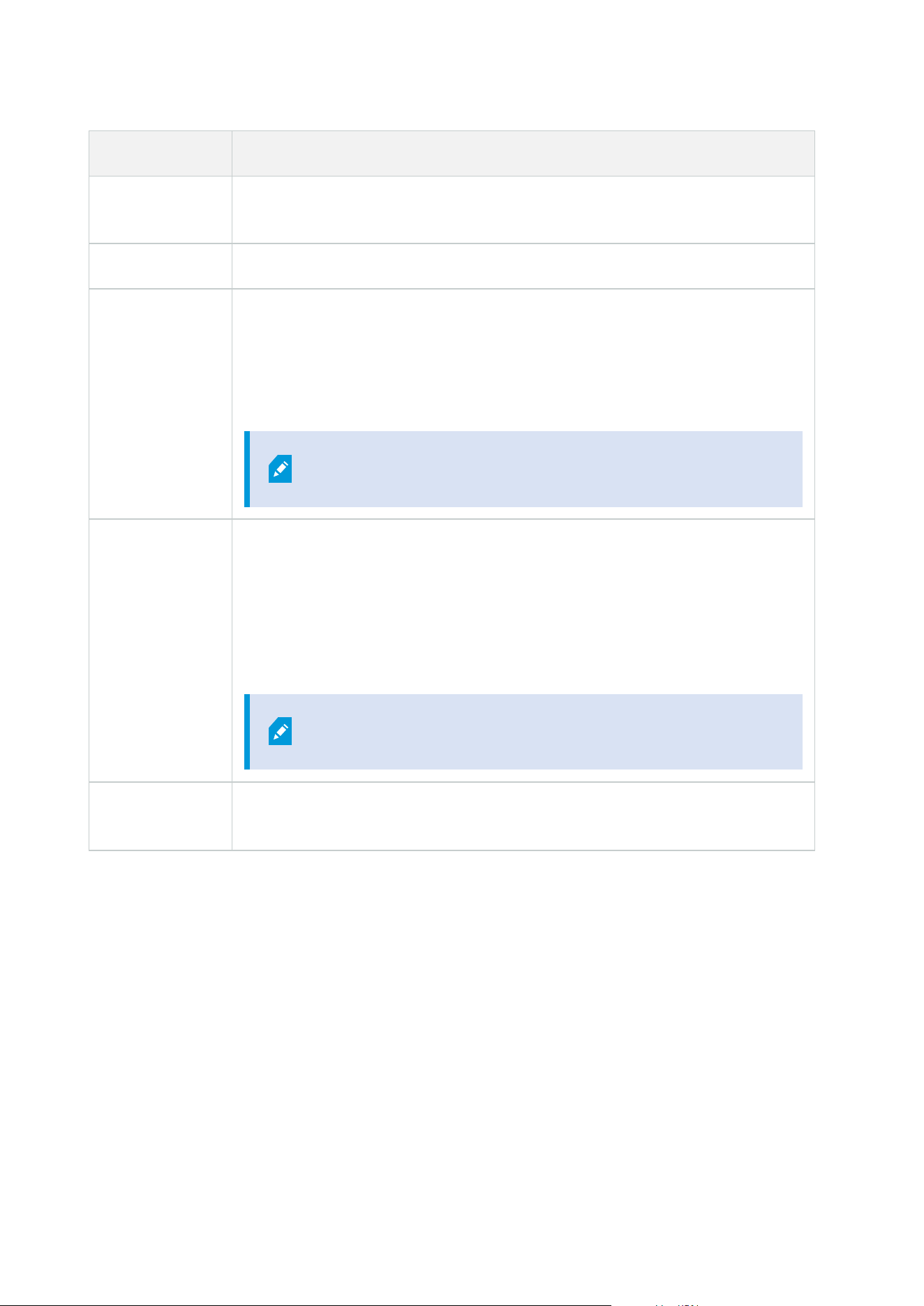
Name Description
Delete
bookmarks
Allows deleting bookmarks in the clients.
AUX commands Allows the use of auxiliary commands from the clients.
Create and
extend evidence
locks
Allows the client user to:
l
Add the camera to new or existing evidence locks
l
Extend the expiry time for existing evidence locks
l
Extend the protected interval for existing evidence locks
Requires user permissions to all devices included in the
evidence lock.
Delete and
reduce evidence
locks
Allows the client user to:
l
Remove the camera from existing evidence locks
l
Delete existing evidence locks
l
Shorten the expiry time for existing evidence locks
l
Shorten the protected interval for existing evidence locks
Requires user permissions to all devices included in the
evidence lock.
Read evidence
locks
Allows the client user to search for and read evidence lock details.
Microphone-related permissions
Specify the following permissions for microphone devices:
Administrator manual | XProtect® VMS 2023 R1
525 | User interface details

Name Description
Read The selected microphone(s) will be visible in the clients.
Listen live
Allows listening to live audio from the selected microphones in the clients.
For XProtect Smart Client, it requires that the role has been granted the permission
to view live video in the clients. This permission is granted as part of the application
permissions. Specify the time profile or leave the default value.
Playback >
Within time
profile
Allows playback of recorded audio from the selected microphone(s) in the clients.
Specify the time profile or leave the default value.
Playback > Limit
playback to
Allows playback of recorded audio from the selected microphone(s) in the clients.
Specify a playback limit or apply no restrictions.
Read sequences
Allows reading the sequence information related to, for example, the Sequence
explorer in the clients.
Export Allows the user to export recordings from the clients.
Start manual
recording
Allows starting manual recording of audio from the selected microphone(s) in the
clients.
Stop manual
recording
Allows stopping manual recording of audio from the selected microphone(s) in the
clients.
Read bookmarks Allows search for and read bookmark details in the clients.
Edit bookmarks Allows editing bookmarks in the clients.
Create
bookmarks
Allows adding bookmarks in the clients.
Delete
bookmarks
Allows deleting bookmarks in the clients.
Create and
extend evidence
Allows the client user to:
Administrator manual | XProtect® VMS 2023 R1
526 | User interface details
Name Description
locks
l
Add the microphone to new or existing evidence locks
l
Extend the expiry time for existing evidence locks
l
Extend the protected interval for existing evidence locks
Requires user permissions to all devices included in the
evidence lock.
Delete and
reduce evidence
locks
Allows the client user to:
l
Remove the microphone from existing evidence locks
l
Delete existing evidence locks
l
Shorten the expiry time for existing evidence locks
l
Shorten the protected interval for existing evidence locks
Requires user permissions to all devices included in the
evidence lock.
Read evidence
locks
Allows the client user to search for and read evidence lock details.
Speaker-related permissions
Specify the following permissions for speaker devices:
Name Description
Read The selected speaker(s) is visible in the clients.
Listen live
Allows listening to live audio from the selected speaker(s) in the clients.
For XProtect Smart Client, it requires that the role has been granted the permission
to view live video in the clients. This permission is granted as part of the application
permissions. Specify the time profile or leave the default value.
Administrator manual | XProtect® VMS 2023 R1
527 | User interface details
Name Description
Playback >
Within time
profile
Allows playback of recorded audio from the selected speaker(s) in the clients. Specify
the time profile or leave the default value.
Playback > Limit
playback to
Allows playback of recorded audio from the selected speaker(s) in the clients. Specify
a playback limit or apply no restrictions.
Read sequences
Allows reading the sequence information related to, for example, the Sequence
explorer in the clients.
Export Allows the user to export recordings from the clients.
Start manual
recording
Allows starting manual recording of audio from the selected speaker(s) in the clients.
Stop manual
recording
Allows stopping manual recording of audio from the selected speaker(s) in the
clients.
Read bookmarks Allows search for and read bookmark details in the clients.
Edit bookmarks Allows editing bookmarks in the clients.
Create
bookmarks
Allows adding bookmarks in the clients.
Delete
bookmarks
Allows deleting bookmarks in the clients.
Create and
extend evidence
locks
Allows the client user to:
l
Add the speaker to new or existing evidence locks
l
Extend the expiry time for existing evidence locks
l
Extend the protected interval for existing evidence locks
Requires user permissions to all devices included in the
evidence lock.
Administrator manual | XProtect® VMS 2023 R1
528 | User interface details
Name Description
Delete and
reduce evidence
locks
Allows the client user to:
l
Remove the speaker from existing evidence locks
l
Delete existing evidence locks
l
Shorten the expiry time for existing evidence locks
l
Shorten the protected interval for existing evidence locks
Requires user permissions to all devices included in the
evidence lock.
Read evidence
locks
Allows the client user to search for and read evidence lock details.
Metadata-related permissions
Specify the following permissions for metadata devices:
Name Description
Read
Enables the permission to see metadata devices and retrieve data from them in the
clients.
Edit
Enables the permission to edit metadata properties. It also allows users to enable or
disable metadata devices in the Management Client and via the MIP SDK.
View Live
Enables the permission to view live metadata from cameras in the clients.
For XProtect Smart Client, it requires that the role has been granted the permission
to view live video in the clients. This permission is granted as part of the application
permissions.
Playback
Enables the permission to play back recorded data from metadata devices in the
clients.
Administrator manual | XProtect® VMS 2023 R1
529 | User interface details
Name Description
Read sequences
Enables the permission to use the Sequences feature while browsing recorded data
from metadata devices in the clients.
Export
Enables the permission to export recorded audio from metadata devices in the
clients.
Create and
extend evidence
locks
Enables the permission to create and extend the evidence locks on metadata in the
clients.
Read evidence
locks
Enables the permission to view evidence locks on metadata in the clients.
Delete and
reduce evidence
locks
Enables the permission to delete or reduce evidence locks on metadata in the clients.
Start manual
recording
Enables the permission to start manual recording of metadata in the clients.
Stop manual
recording
Enables the permission to stop manual recording of metadata in the clients.
Input-related permissions
Specify the following permissions for input devices:
Name Description
Read The selected input(s) will be visible in the clients.
Output-related permissions
Specify the following permissions for output devices:
Administrator manual | XProtect® VMS 2023 R1
530 | User interface details

Name Description
Read
The selected output(s) will be visible in the clients. If visible, the output will be
selectable on a list in the clients.
Activate
The selected output(s) can be activated from the Management Client and the clients.
Specify the time profile or leave the default value.
PTZ tab (roles)
You set up permissions for pan-tilt-zoom (PTZ) cameras on the PTZ tab. You can specify the features
users/groups can use in the clients. You can select individual PTZ cameras or device groups containing PTZ
cameras.
Specify the following permissions for PTZ:
Name Description
Manual PTZ
Determines if the selected role can use PTZ functions and pause a patrolling on the
selected camera.
Specify a time profile, select Always, or leave the default value that follows the
default time profile defined on the Info tab for that role.
Activate PTZ
presets or
patrolling
profiles
Determines if the selected role can move the selected camera to preset positions,
start and stop patrolling profiles, and pause a patrolling.
Specify a time profile, select Always, or leave the default value that follows the
default time profile defined on the Info tab for that role.
To allow this role to use other PTZ functions on the camera, enable the Manual PTZ
permission.
PTZ Priority
Determines the priority of PTZ cameras. When several users on a surveillance system
want to control the same PTZ camera at the same time, conflicts may occur.
You can avoid such a situation by specifying a priority for use of the selected PTZ
camera(s) by users/groups with the selected role. Specify a priority from 1 to 32,000,
where 1 is the lowest priority. The default priority is 3,000. The role with the highest
priority number is the one who can control the PTZ camera(s).
Administrator manual | XProtect® VMS 2023 R1
531 | User interface details

Name Description
Manage PTZ
presets or
patrolling
profiles
Determines the permission to add, edit and delete PTZ presets and patrolling
profiles on the selected camera in both the Management Client and XProtect Smart
Client.
To allow this role to use other PTZ functions on the camera, enable the Manual PTZ
permission.
Lock/unlock PTZ
presets
Determines if the role can lock and unlock preset positions for the selected camera.
Reserve PTZ
sessions
Determines the permission to set the selected camera in reserved PTZ session mode.
In a reserved PTZ session other users or patrolling sessions with higher PTZ priority
are not able to take over the control.
To allow this role to use other PTZ functions on the camera, enable the Manual PTZ
permission.
Release PTZ
sessions
Determines if the selected role can release other users' PTZ sessions from the
Management Client.
You can always release your own PTZ sessions - without this permission.
Speech tab (roles)
Relevant only if you use speakers on your system. Specify the following permissions for speakers:
Name Description
Speak
Determine if users should be allowed to talk through the selected speaker(s). Specify the
time profile or leave the default value.
Speak
priority
When several client users want to talk through the same speaker at the same time, conflicts
may occur.
Solve the problem by specifying a priority for use of the selected speaker(s) by users/groups
with the selected role. Specify a priority from Very low to Very high. The role with the
highest priority is allowed use the speaker before other roles.
Should two users with the same role want to speak at the same time, the first come, first
served-principle applies.
Administrator manual | XProtect® VMS 2023 R1
532 | User interface details
Remote Recordings tab (roles)
Specify the following permissions for remote recordings:
Name Description
Retrieve
remote
recordings
Enables the permission to retrieve recordings in the clients from cameras, microphones,
speakers, and metadata devices on remotes sites or from edge storages on cameras.
Smart Wall tab (roles)
Through roles, you can grant your client users Smart Wall-related user permissions:
Name Description
Read Allows users to view the selected Smart Wall in XProtect Smart Client.
Edit Allows users to edit the selected Smart Wall in the Management Client.
Delete Allows users to delete the selected Smart Wall in the Management Client.
Operate
Allows users to apply layouts on the selected Smart Wall in XProtect Smart Client and to
activate presets.
Playback
Allows users to play back recorded data from the selected Smart Wall in XProtect Smart
Client.
External Event tab (roles)
Specify the following external event permissions:
Name Description
Read
Allows users to search for and view the selected external system event in the clients and the
Administrator manual | XProtect® VMS 2023 R1
533 | User interface details
Name Description
Management Client.
Edit Allows users to edit the selected external system event in the Management Client.
Delete Allows users to delete the selected external system event in the Management Client.
Trigger Allows users to trigger the selected external system event in the clients.
View Group tab (roles)
On the View Group tab, you specify which view groups the users and user groups with the selected role can
use in the clients.
Specify the following permissions for view groups:
Name Description
Read
Enables the permission to view the View Groups in the clients and in the Management
Client. View groups are created in the Management Client.
Edit Enables the permission to edit properties on View Groups in the Management Client.
Delete Enables the permission to delete View Groups in the Management Client.
Operate
Enables the permission to use View Groups in XProtect Smart Client, that is to create and
delete subgroups and views.
Servers tab (roles)
Specifying role permissions on the Servers tab is only relevant if your system works in a Milestone Federated
Architecture setup.
Administrator manual | XProtect® VMS 2023 R1
534 | User interface details
Name Description
Sites
Enables the permission to view the selected site in the Management Client. Connected sites
are connected via Milestone Federated Architecture.
To edit properties, you need Edit permissions on the Management Server on each site.
See Configuring Milestone Federated Architecture on page 87 for more information.
Matrix tab (roles)
If you have configured Matrix recipients on your system, you may configure Matrix role permissions. From a
client, you can send video to selected Matrix recipients. Select the users who can receive this on the Matrix tab.
The following permissions are available:
Name Description
Read
Determine if users and groups with the selected role can select and send video to the Matrix
recipient from the clients.
Alarms tab (roles)
If you use alarms in your system setup to provide central overview and control of your installation (including
any other XProtect servers), you can use the Alarms tab to specify the alarm permissions for users and groups
with the selected role they should have, for example, how to handle alarms in the clients.
Specify the following permissions for alarms:
Name Description
Manage
Enables the permission to manage alarms, for example changing priorities of alarms
and re-delegate alarms to other users, acknowledge alarms and change the state, for
example from New to Assigned, of several alarms at the same time.
View Enables the permission to view alarms and print alarm reports.
Administrator manual | XProtect® VMS 2023 R1
535 | User interface details

Name Description
Disable alarms Enables the permission to disable alarms.
Receive
notifications
Enables the permission to receive notifications about alarms in XProtect Mobile clients
and XProtect Web Client.
Access Control tab (roles)
When you add or edit basic users, Windows users or groups, specify access control settings:
Name Description
Use access control Allows the user to use any access control-related features in the clients.
View cardholders
list
Allows the user to view the cardholders list on the Access Control tab in the
clients.
Receive
notifications
Allows the user to receive notifications about access requests in the clients.
LPR tab (roles)
If your system runs with XProtect LPR, specify the following permissions for the users:
Name Description
Use LPR Enables the permission to use any LPR-related features in the clients.
Manage match
lists
Enables the permission to add, import, modify, export, and delete match lists in the
Management Client.
Read match
lists
Enables the permission to view match lists.
Administrator manual | XProtect® VMS 2023 R1
536 | User interface details

Incidents tab (roles)
If you have XProtect Incident Manager, you can specify the following permissions for your roles.
To give a Management Client administrator role the permissions to manage or view incident properties, select
the Incident properties node.
To give an operator of XProtect Smart Client permission to view your defined incident properties, select
Incident properties and give View permission. To give general permissions to manage or view incident
projects, select the Incident project node. Expand the Incident project node and select one or more sub-
nodes to give permissions for these additional specific features or capabilities.
Name Description
Manage
Permission to manage (view, create, edit, and delete) settings and properties related to a
feature or view a user interface element represented by the selected node in either
Management Client or XProtect Smart Client.
View
Permission to view (but not create, edit, and delete) the settings and properties related to a
feature, view defined incident properties, or view a user interface element represented by
the selected node in either Management Client or XProtect Smart Client.
MIP tab (roles)
Through the MIP SDK, a third-party vendor can develop custom plug-ins for your system, for example,
integration to external access control systems or similar functionality.
The settings you change depend on the actual plug-in. Find the custom settings for the plug-ins on the MIPtab.
Basic user (Security node)
When you add a basic user to your system, you create a dedicated surveillance system user account with basic
user name and password authentication for the individual user. This is in contrast to the Windows user, added
through Active Directory.
When working with basic users, it is important to understand the difference between basic user and Windows
user.
l
Basic users are authenticated by a user name/password combination and are specific to a system.
Even if basic users have the same name and password, a basic user created at one federated site does
not have access to another federated site
l
Windows users are authenticated based on their Windows login and are specific to a machine
Administrator manual | XProtect® VMS 2023 R1
537 | User interface details

System dashboard node
System Dashboard node
Under the System Dashboard node, you find different functionality to monitor your system and its various
system components.
Name Description
Current Task Get an overview of ongoing tasks on a selected recording server.
System Monitor Monitor the status of your servers and cameras by parameters you define.
System Monitor
Thresholds
Set threshold values for monitored parameters on server and monitor tiles used
in System Monitor.
Evidence Lock Get an overview of all protected data in the system.
Configuration
Reports
Print a report with your system configuration. You can decide what to include in
the report.
Current Tasks (System Dashboard node)
The Current Tasks window shows an overview of ongoing tasks under a selected recording server. If you have
initiated a task that takes a long time and runs in the background, you can open the Current Tasks window to
see how the task progresses. A few examples of lengthy user-initiated tasks are firmware updates and
movement of hardware. You can see information about the task's start-time, estimated end-time, and
progress.
The information shown in the Current Tasks window is not dynamically updated but is a snapshot of the
current tasks from the moment you opened the window. If you have had the window open for some time,
refresh the information by selecting the Refresh button in the lower right corner of the window.
System Monitor (System Dashboard node)
The System Monitor functionality provides you with a quick, visual overview of the current well-being of your
system's servers and cameras.
Administrator manual | XProtect® VMS 2023 R1
538 | User interface details
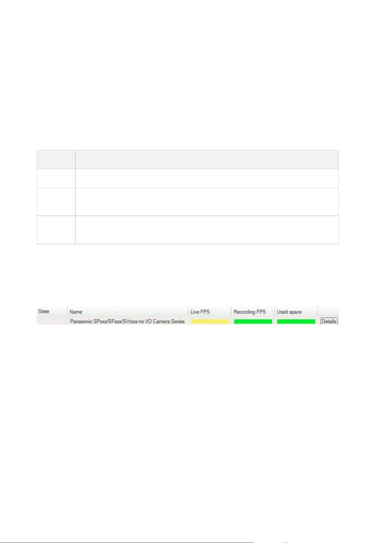
System monitor dashboard window
Tiles
The upper part of the System monitor dashboard window shows colored tiles that represent the state of your
system's server hardware and camera hardware.
The tiles change their state and thereby color based on threshold values set under System Monitor
Thresholds node. For more information, see System Monitor Thresholds (System Dashboard node) on page
541. Define the thresholds, so tile colors mean the following:
Tile color Description
Green Normal state. Everything is running normally.
Yellow
Warning state. One or more monitoring parameters is above the threshold value for the
Normal state.
Red
Critical state. One or more monitoring parameters is above the threshold value for the
Normal and Warning state.
Hardware list with monitoring parameters
If you click a tile, you can see the state of each selected monitoring parameter for each hardware represented
by the tile in the bottom part of the System monitor dashboard window.
Example: A camera's LIVE FPS monitoring parameters have reached the Warning state.
Customize dashboard window
Select Customize in the upper right corner of the window to open the Customize dashboard window.
In the Customize dashboard window, you can select which tile to create, edit or delete. When creating or
editing tiles, you can select which hardware and which monitoring parameters you want to monitor on the tile.
Details window
If you select a tile and then from the hardware list with monitoring parameters, select the Details button to the
right of a camera or server, you can -depending on the selected hardware - view system information and
create reports regarding:
Administrator manual | XProtect® VMS 2023 R1
539 | User interface details

Hardware Information
Management
server
Shows data about:
l
CPU Usage
l
Memory available
Select History to see the historical states of your hardware and
create a report on the above data.
Recording
server(s)
Shows data about:
l
CPU usage
l
Memory available
l
Disks
l
Storage
l
Network
l
Cameras
Select History to see the historical states of your hardware and
create a report on the above data.
Failover
recording
servers
Shows data about:
l
CPU usage
l
Memory available
l
Monitored recording servers
Select History to see the historical states of your hardware and
create a report on the above data.
Log servers,
events servers,
and more
Shows data about
l
CPU usage
l
Memory available
Select History to see the historical states of your hardware and
create a report on the above data.
Administrator manual | XProtect® VMS 2023 R1
540 | User interface details
Hardware Information
Cameras
Shows data about:
l
Storage
l
Used Space
l
Live FPS (Default)
l
Recording FPS
l
Live Video Format
l
Recording Video Format
l
Media Data Received (Kbit/s)
l
Memory available
Select the camera name to see its historical states and create a
report on:
l
Data received from camera
l
Camera disk usage
If you access the system monitor's details from a server operating system, you may
experience a message regarding Internet Explorer Enhanced Security Configuration.
Follow the instructions to add the System Monitor page to the Trusted sites zone
before proceeding.
System Monitor Thresholds (System Dashboard node)
System monitor thresholds allow you to define and adjust the thresholds when tiles on the System monitor
dashboard should visually indicate that your system hardware changes state. For example, when the CPU
usage of a server changes from a normal state (green) state to a warning state (yellow) or from a warning state
(yellow) to a critical state (red).
Administrator manual | XProtect® VMS 2023 R1
541 | User interface details

Example of thresholds between the three states
You can change thresholds for servers, cameras, disks, and storage, and all thresholds have some common
buttons and settings.
Common user interface elements
Buttons &
settings
Description Unit
Calculation
interval
Often there are short outages in the connection to your different hardware.
If you specify a calculation interval of 0 seconds, all these short outages will
trigger alerts about changes in hardware state. Therefore, define a
calculation interval of some length.
If you define a one (1) minute calculation internal, it means that you only get
alerts if the average value for the whole minute exceeds the threshold. With
the correct calculation interval setting, you will not receive false-positive
alerts but only alerts about sustained issues with, for example, CPU usage
or memory consumption.
To change the values of calculation intervals, see Edit thresholds for when
hardware states should change on page 281.
sec
Advanced
If you select the Advanced button, you can define thresholds and
calculation intervals for individual servers, cameras, disks, and storage. For
more information, see below.
-
Create rule
You can combine events from System Monitor and rules to trigger actions,
for example, when a server's CPU usage is critical, or a disk is running out of
free space.
For more information, see Rules and events (explained) on page 74 and Add
rules on page 259.
-
Administrator manual | XProtect® VMS 2023 R1
542 | User interface details

Server thresholds
Threshold Description Unit
CPU usage Thresholds for the CPU usage on the servers you monitor. %
Memory available Thresholds for RAM in use on the servers you monitor. MB
NVIDIA decoding Thresholds for the NVIDIA decoding usage on the servers you monitor. %
NVIDIA memory Thresholds for NVIDIA RAM in use on the servers you monitor. %
NVIDIA rendering Thresholds for the NVIDIA rendering usage on the servers you monitor. %
Camera thresholds
Threshold Description Unit
Live FPS
Thresholds for cameras' FPS in use when live video is shown on cameras you
monitor.
%
Recording
FPS
Thresholds for cameras' FPS in use when the system is recording video on
cameras, you monitor.
%
Used space Thresholds for the space used by cameras you monitor. GB
Disk thresholds
Threshold Description Unit
Free space Thresholds for available space on disks you monitor. GB
Administrator manual | XProtect® VMS 2023 R1
543 | User interface details

Storage thresholds
Threshold Description Unit
Retention
time
Threshold showing a prediction for when you run out of space on
your storage. The state shown is based on your system setup and is
updated twice a day.
Days
Evidence Lock (System Dashboard node)
Evidence Lock under the System Dashboard node shows an overview of all protected data on the current
surveillance system.
The following metadata is available for all evidence locks:
l
Start and end date for the protected data
l
The user who locked the evidence
l
When the evidence is no longer locked
l
Where the data is stored
l
The size of each evidence lock
All information shown in the Evidence Lock window is snapshots. Press F5 to refresh.
Configuration Reports (System Dashboard node)
You make many choices when you install and configure your VMS system, and you may need to document
these. Over time it is also hard to remember all the settings you have changed since the installation and initial
configuration - or just during the last couple of months. That is why it is possible to print a report with all your
configuration choices.
The following settings are available when creating and printing configuration reports:
Name Description
Reports A list of elements that is possible to include in a configuration report.
Select All Adds all elements in the Reports list to the configuration report.
Administrator manual | XProtect® VMS 2023 R1
544 | User interface details
Name Description
Clear All Removes all elements in the Reports list from the configuration report.
Front Page Customize the front page of the report.
Formatting Format the report.
Exclude
sensitive data
Removes personal data like user names, e-mail addresses, and other types of sensitive
data from the configuration report and makes it GDPR compliant.
Information about the license owner is always exclude from the report.
Export Select a save location for the report and create it as a PDF.
Server Logs node
Server Logs node
System logs (tab)
Each row in a log represents a log entry. A log entry contains a number of information fields:
Name Description
Log level Info, warning, or error.
Local time Timestamped in the local time of your system's server.
Message text The identification number for the logged incident.
Category The type of logged incident.
Source type
The type of equipment on which the logged incident occurred, for
example, server or device.
Source name The name of the equipment on which the logged incident occurred.
Event type The type of event represented by the logged incident.
Administrator manual | XProtect® VMS 2023 R1
545 | User interface details
Audit logs (tab)
Each row in a log represents a log entry. A log entry contains a number of information fields:
Name Description
Local time Timestamped in the local time of your system's server.
Message text Shows a description of the logged incident.
Permission The information about whether the remote user action was allowed (granted) or not.
Category The type of logged incident.
Source type
The type of equipment on which the logged incident occurred, for example, server or
device.
Source name The name of the equipment on which the logged incident occurred.
User The user name of the remote user causing the logged incident.
User location
The IP address or host name of the computer from which the remote user caused the
logged incident.
Rule-triggered logs (tab)
Each row in a log represents a log entry. A log entry contains a number of information fields:
Name Description
Local time Timestamped in the local time of your system's server.
Message text Shows a description of the logged incident.
Category The type of logged incident.
Source type
The type of equipment on which the logged incident occurred, for
Administrator manual | XProtect® VMS 2023 R1
546 | User interface details

Name Description
example, server or device.
Source name The name of the equipment on which the logged incident occurred.
Event type The type of event represented by the logged incident.
Rule name The name of the rule triggering the log entry.
Service name The name of the service on which the logged incident occurred.
Metadata Use node
Metadata and metadata search
To manage and configure metadata devices, see Show or hide metadata search
categories and search filters on page 283.
What is metadata?
Metadata is data about data, for example, data that describes the video image, the content or objects in the
image, or the location of where the image was recorded.
Metadata can be generated by:
l
The device itself delivering the data, for example a camera that is delivering video
l
A third-party system or integration via a generic metadata driver
Metadata search
Metadata search is any search for video recordings in XProtect Smart Client that uses search categories and
search filters related to metadata.
The default Milestone metadata search categories are:
l
Location
l
People
l
Vehicles
Administrator manual | XProtect® VMS 2023 R1
547 | User interface details

Metadata search requirements
To get search results, you need one of the following:
l
At least one device in your video surveillance system that can perform video analytics and is configured
correctly
l
A video processing service in your video surveillance system that generates metadata
In either case, metadata must be in the required metadata format.
For more information, see the documentation for integration of Metadata Search.
Access Control node
Access control properties
General Settings tab (Access Control)
Name Description
Enable
Systems are by default enabled, meaning that they are visible in XProtect Smart
Client for users with sufficient permissions and that the XProtect system receives
access control events.
You can disable a system, for example during maintenance, to avoid creating
unnecessary alarms.
Name
The name of the access control integration as it appears in the management
application and in the clients. You can overwrite the existing name with a new one.
Description Provide a description of the access control integration. This is optional.
Integration
plug-in
Shows the type of access control system selected during the initial integration.
Last
configuration
refresh
Shows the date and time of the last time the configuration was imported from the
access control system.
Refresh
configuration
Click the button when you need to reflect configuration changes made in the access
control system in XProtect, for example if you have added or deleted a door.
Administrator manual | XProtect® VMS 2023 R1
548 | User interface details

Name Description
A summary of the configuration changes from the access control system appears.
Review the list to ensure that your access control system is reflected correctly before
you apply the new configuration.
Operator login
required
Enable an additional login for the client users, if the access control system supports
differentiated user permissions. If you enable this option, the access control system
will not be available in XProtect Mobile client.
This option is only visible if the integration plug-in supports differentiated user
permissions.
The naming and content of the following fields are imported from the integration plug-in. Below are examples
of some typical fields:
Name Description
Address Enter the address of the server that hosts the integrated access control system.
Port Specify the port number on the server to which the access control system is connected.
User name
Enter the name of the user, as defined in the access control system, who should be
administrator of the integrated system in XProtect.
Password Specify the password for the user.
Doors and Associated Cameras tab (Access Control)
This tab provides mappings between door access points and cameras, microphones or speakers. You associate
cameras as part of the integration wizard, but you can change the setup at any time. Mappings to
microphones and speakers are implicit through the related microphone or speaker on the camera.
Administrator manual | XProtect® VMS 2023 R1
549 | User interface details

Name Description
Doors
Lists the available door access points defined in the access control system, grouped by
door.
For an easier navigation to the relevant doors, you can filter on the doors in your access
control system with the dropdown list box at the top.
Enabled: Licensed doors are by default enabled. You can disable a door to free a license.
License: Shows if a door is licensed or if the license has expired. The field is blank when
the door is disabled.
Remove: Click Remove to remove a camera from an access point. If you remove all
cameras, the check box for associated cameras is automatically cleared.
Cameras
Lists the cameras configured in the XProtect system.
Select a camera from the list and drag and drop it at the relevant access point to associate
the access point with the camera.
Access Control Events tab (Access Control)
Event categories allow you to group events. The configuration of event categories affects the behavior of
access control in the XProtect system and allows you to, for example, define an alarm to trigger a single alarm
on multiple event types.
Name Description
Access
Control Event
Lists the access control events imported from the access control system. The integration
plug-in controls default enabling and disabling of events. You can disable or enable
events any time after the integration.
When an event is enabled, it is stored in the XProtect event database and is, for example,
available for filtering in the XProtect Smart Client.
Source Type Shows the access control unit that can trigger the access control event.
Event
Category
Assign none, one or more event categories to the access control events. The system
automatically maps relevant event categories to the events during integration. This
enables a default setup in the XProtect system. You can change the mapping at any
Administrator manual | XProtect® VMS 2023 R1
550 | User interface details
Name Description
time.
Built-in event categories are:
l
Access denied
l
Access granted
l
Access request
l
Alarm
l
Error
l
Warning
Events and event categories defined by the integration plug-in also appear, but you can
also define your own event categories, see User-defined Categories.
If you change the event categories in XProtect Corporate, ensure
that the existing access control rules still work.
User-defined
Categories
Allows you to create, modify or delete user-defined event categories.
You can create event categories when the built-in categories do not meet your
requirements, for example, in connection with defining triggering events for access
control actions.
The categories are global for all integration systems added to the XProtect system. They
allow setting up cross-system handling, for example on alarm definitions.
If you delete a user-defined event category, you receive a warning if it is used by any
integration. If you delete it anyway, all configurations made with this category, for
example access control actions, do not work anymore.
Access Request Notification tab (Access Control)
You can specify access request notifications that appear on the XProtect Smart Client screen when a given
event occurs.
Administrator manual | XProtect® VMS 2023 R1
551 | User interface details
Name Description
Name Enter a name for the access request notification.
Add Access
Request
Notification
Click to add and define access request notifications.
To delete a notification, click X on the right-hand side.
If a user of XProtect Smart Client logs into a parent site in a
Milestone Federated Architecture hierarchy, access request
notifications from the child sites also appear in XProtect Smart
Client.
Access request
notification
details
Specify which cameras, microphones or speakers that appear in the access request
notifications when a given event occurs. Also specify the sound to alert the user when
the notification pops up.
Add command
Select which commands that should be available as buttons in the access request
notification dialogs in the XProtect Smart Client.
Related access request commands:
l
Enables all commands related to access request operations available on the
source unit. For example Open door
All related commands:
l
Enables all commands on the source unit
Access control command:
l
Enables a selected access control command
System command:
l
Enables a command predefined in the XProtect system
To delete a command, click X on the right-hand side.
Cardholders tab (Access Control)
Use the Cardholders tab to review information about cardholders in the access control system.
Administrator manual | XProtect® VMS 2023 R1
552 | User interface details

Name Description
Search cardholder Enter the characters of a cardholder name and it appears in the list, if it exists.
Name Lists the names of the cardholders retrieved from the access control system.
Type
Lists the type of cardholder, for example:
l
Employee
l
Guard
l
Guest
If your access control system supports adding/deleting pictures in the XProtect system, you can add pictures to
the cardholders. This is useful if your access control system does not include pictures of the cardholders.
Name Description
Select
picture
Specify the path to a file with a picture of the cardholder. This button is not visible if the
access control system manages the pictures.
Allowed file-formats are .bmp, .png, and .jpg.
Pictures are resized to maximize the view.
Milestone recommends that you use a quadratic picture.
Delete
picture
Click to delete the picture. If the access control system had a picture, then this picture is
shown after deletion.
Incidents node
Incident properties (Incidents node)
The following information describes settings that are related to XProtect Incident Manager.
You define all incident properties for your XProtect Smart Client operators on these tabs:
Administrator manual | XProtect® VMS 2023 R1
553 | User interface details
l
Types
l
Statuses
l
Categories
l
Category 1-5
All the incident properties have the following settings:
Name Description
Name
Incident property names do not have to be unique, but it is an advantage to use unique
and descriptive incident property names in many situations.
Description
An additional explanation of the defined incident property. For example, if you have
created a category named Location, its description could be Where did the incident
happen?
Transact node
Transaction Sources (Transact node)
The following table describes the properties for transaction sources.
For more information about adding a source, see Add transaction source (wizard).
Transaction sources (properties)
Name Description
Enable
If you want to disable the transaction source, clear this check box. The stream of
transaction data stops, but the data already imported remains on the event server. You
can still view transactions from a disabled transaction source in XProtect Smart Client
during its retention period.
Even a disabled transaction source requires a transaction source
license.
Administrator manual | XProtect® VMS 2023 R1
554 | User interface details

Name Description
Name If you want to change the name, enter a new name here.
Connector
You cannot change the connector you selected when you created the transaction
source. To select a different connector, you need to create a new transaction source,
and during the wizard, select the connector you want.
Transaction
definition
You can select a different transaction definition that defines how to transform the
transaction data received into transactions and transaction lines. This includes defining:
l
When a transaction begins and ends
l
How transactions are displayed in XProtect Smart Client
Retention
period
Specify, in days, for how long transaction data is maintained on the event server. The
default retention period is 30 days. When the retention period expires, automatically
the data is deleted. This is to avoid the situation, where the storage capacity of the
database is exceeded.
The minimum value is 1 day, whereas the maximum value is 1000 days.
TCP client
connector
If you selected TCP client connector, specify these settings:
l
Host name: enter the host name of the TCP server associated with the
transaction source
l
Port: enter the port name on the TCP server associated with the transaction
source
Serial port
connector
If you selected Serial port connector, specify these settings and make sure that they
match the settings on the transaction source:
l
Serial port: select the COM port
l
Baud rate: specify the number of bits transmitted per second
l
Parity: specify the method for detecting errors in the transmissions. By default,
None is selected
l
Data bits: specify the number of bits used to represent one character of data
l
Stop bits: specify the number of bits to indicate when a byte has been
transmitted. Most devices need 1 bit
l
Handshake: specify the handshaking method determining the communication
protocol between the transaction source and event server
Administrator manual | XProtect® VMS 2023 R1
555 | User interface details

Transaction Definitions (Transact node)
The following table describes the properties for definitions to be used for the transaction sources.
For more information about creating and adding transaction definitions, see Create and add transaction
definitions.
Transaction definitions (properties)
Name Description
Name Enter a name.
Encoding
Select the character set used by the transaction source, for example the cash register.
This helps XProtect Transact convert the transaction data to understandable text that
you can work with when configuring the definition.
If you select the wrong encoding, the data may appear as non-sense text.
Start collecting
data
Collect transaction data from the connected transaction source. You can use the data
to configure a transaction definition.
Wait for at least one, but preferably more, transactions to complete.
Stop collecting
data
When you have collected sufficient data to configure the definition, click this button.
Load from file
If you want to import data from an already existing file, click this button. Typically this
is a file that you have created previously in the file format .capture. It can be other file
formats. What is important here is that the encoding of the import file matches the
encoding selected for the current definition.
Save to file
If you want to save the collected raw data to a file, click this button. You can reuse it
later.
Match type
Select the match type to use to search for the start pattern and the stop pattern in the
collected raw data:
l
Use exact match: The search identifies strings that contain exactly what you
have entered in the Start pattern and Stop pattern fields
Administrator manual | XProtect® VMS 2023 R1
556 | User interface details

Name Description
l
Use wildcards: The search identifies strings that contain what you have entered
in the Start pattern and Stop pattern fields in combination with a wild card
symbol (*, #, ?)
* matches any number of characters. For example, if you have entered "Start
tra*tion", the search identifies strings that contain "Start transaction".
# matches exactly 1 digit. For example, if you have entered "# watermelon", the
search identifies strings that contain, for example, "1 watermelon".
? matches exactly 1 character. For example, you may use the search expression
"Start trans?ction" to identify strings that contain "Start transaction"
l
Use regular expression: Use this match type to identify strings that contain
specific notation methods or conventions, for example a date format or credit
card number. For more information, see the Microsoft website
(https://docs.microsoft.com/dotnet/standard/base-types/regular-expression-
language-quick-reference/)
Raw data
Transaction data strings from the connected transaction source are displayed in this
section.
Start pattern
Specify a start pattern to indicate where a transaction begins. Horizontal lines are
inserted in the Preview field to visualize where the transaction starts and ends, and
will help to keep individual transactions separated.
Stop pattern
Specify a stop pattern to indicate where a transaction ends. A stop pattern is not
mandatory, but is useful if the received data contains irrelevant information, such as
information about opening hours or special offers, between actual transactions.
If you do not specify a stop pattern, the end of the receipt is defined in terms of where
the next receipt starts. The start is determined by what is entered in the Start pattern
field.
Add filter
Use the Add filters button to point out the characters that you want to be omitted in
XProtect Smart Client or replaced by other characters or a line break.
Replacing characters is useful when the transaction source string contains control
characters for non-printing purposes. Adding line breaks is necessary to make receipts
in XProtect Smart Client resemble the original receipts.
Filter text
Displays the characters currently selected in the Raw data section. If you are aware of
Administrator manual | XProtect® VMS 2023 R1
557 | User interface details

Name Description
characters that you want to be omitted or replaced, but they do not occur in the
collected raw data string, you can enter the characters manually in the Character field.
If the character is a control character, you need to enter its hexadecimal byte value.
Use this format for the byte value: {XX} and {XX, XX,...} if a characters consists of more
bytes.
Action
For each filter you add, you should specify how the characters you have selected are
handled:
l
Omit: the characters you select are filtered out
l
Substitute: the characters you select are replaced with the characters you
specify
l
Add line break: the characters you select are replaced by a line break
Substitution
Enter the text to replace the characters selected. Only relevant if you have selected the
action Substitute.
Remove
control
characters that
are not defined
as filter text
Remove non-printing characters that were not already removed after adding filters.
In the Raw data pane and the Preview section, see how the transaction data strings
change when you enable or disable this setting.
Preview
Use the Preview section to verify that you have identified and filtered out unwanted
characters. The output you see here resembles what the real-life receipt looks like in
XProtect Smart Client.
Alarms node
Alarm Definitions (Alarms node)
When your system registers an event on your system, you can configure the system to generate an alarm in
XProtect Smart Client. You must define alarms before you can use them, and alarms are defined based on
events registered in your system servers. You can also use user-defined events for triggering alarms and use
the same event to trigger several different alarms.
Administrator manual | XProtect® VMS 2023 R1
558 | User interface details

Alarm definition settings:
Name Description
Enable By default, the alarm definition is enabled. To disable it, clear the check box.
Name
Alarm names do not have to be unique, but using unique and descriptive alarm names
are advantageous in many situations.
Instructions
Enter a descriptive text about the alarm and how to resolve the issue that caused the
alarm.
The text appears in XProtect Smart Client when the user handles the alarm.
Triggering
event
Select the event message to use when the alarm is triggered. Choose from two
dropdowns:
l
The first drop-down: Select the type of event, for example analytics event and
system events
l
The second drop-down: Select the specific event message to use. The messages
available are determined by the event type you selected in the first drop-down
menu
Sources
Specify the sources that the events originate from. Aside from cameras or other
devices, sources may also be plug-in defined sources, for example VCA and MIP. The
options depend on the type of event you have selected.
Alarm trigger:
Name Description
Time
profile
Select the Time profile radio button to specify the time interval during which the alarm
definition is active. Only the time profile you have defined under the Rules and Events node
are displayed in the list. If none are defined, only the Always option is available.
Event
based
If you want the alarm to be based on an event, select this radio button. Once selected,
specify the start and stop event. You can select hardware events defined on cameras, video
servers and input. See also Events overview. Also, global/manual event definitions can be
used. See also User-defined events (explained).
Administrator manual | XProtect® VMS 2023 R1
559 | User interface details
Operator action required:
Name Description
Time limit
Select a time limit for when operator action is required. The default value is 1 minute. The
time limit is not active before you have attached an event in the Events triggered drop-
down menu.
Events
triggered
Select which event to trigger when the time limit has passed.
Maps:
Name Description
Alarm Manager
view
Assign either a smart map or a map to the alarm when the alarm is listed in XProtect
Smart Client > Alarm Manager.
Smart map displays alarms if they are triggered by a device
and if the device is added to the smart map.
Other:
Name Description
Related cameras
Select up to 15 cameras to include in the alarm definition, even
if these cameras themselves do not trigger the alarm. This can
be relevant, for example, if you have selected an external event
message (such as a door being opened) as the source of your
alarm. By defining one or more cameras near the door, you can
attach the cameras' recordings of the incident to the alarm.
Administrator manual | XProtect® VMS 2023 R1
560 | User interface details

Name Description
Initial alarm owner Select a default user responsible for the alarm.
Initial alarm
priority
Select a priority for the alarm. Use these priorities in XProtect
Smart Client to determine the importance of an alarm.
Alarm category
Select an alarm category for the alarm, for example False
alarm or Need investigation.
Events triggered by
alarm
Define an event that the alarm can trigger in XProtect Smart
Client.
Auto-close alarm
If you want a particular event to automatically stop the alarm,
select this check box. Not all events can trigger alarms. Clear
the check box to disable the new alarm from the beginning.
Alarm assignable
to Administrators
Select the check box to include users with an administrator role
in the Assigned to list.
The Assigned to list is in the alarm details on the Alarm
Manager tab in XProtect Smart Client.
Clear the check box to filter out users with an administrator
role from the Assigned to list to shorten the list.
Alarm Data Settings (Alarms node)
When you configure alarm data settings, specify the following:
Alarm Data Levels tab
Priorities
Name Description
Level
Add new priorities with level numbers of your choosing or use/edit the default priority
levels (numbers 1, 2 or 3). These priority levels are used to configure the Initial alarm
priority setting.
Administrator manual | XProtect® VMS 2023 R1
561 | User interface details
Name Description
Name Enter a name for the entity. You can create as many as you like.
Sound
Select the sound to be associated with the alarm. Use one of the default sounds or add
more in Sound Settings.
Repeat sound
Decide whether the sound should play only once or repeatedly until in XProtect Smart
Client, the operator clicks the alarm in the alarm list.
Enable desktop
notifications
For each alarm priority, you can enable or disable desktop notifications. If you are
using an XProtect VMS that supports Smart Client profiles, you must also enable
notifications on the required Smart Client profiles. See Alarm Manager tab (Smart
Client profiles) on page 454.
States
Name Description
Level
In addition to the default state levels (numbers 1, 4, 9 and 11, which cannot be edited or
reused), add new states with level numbers of your choosing. These state levels are only
visible in the XProtect Smart Client's Alarm List.
Categories
Name Description
Level
Add new categories with level numbers of your choosing. These category levels are used to
configure the Initial alarm category setting.
Name Enter a name for the entity. You can create as many as you like.
Administrator manual | XProtect® VMS 2023 R1
562 | User interface details

Alarm List Configuration tab
Name Description
Available
columns
Use > to select which columns should be available in the XProtect Smart Client's Alarm List.
Use < to clear selection. When done, Selected columns should contain the items to be
included.
Reasons for Closing tab
Name Description
Enable
Select to enable that all alarms must be assigned a reason for closing before they can be
closed.
Reason
Add reasons for closing that the user can choose between when closing alarms. Examples
could be Solved-Trespasser or False Alarm. You can create as many as you like.
Sound Settings (Alarms node)
When you configure sound settings, specify the following:
Name Description
Sounds
Select the sound to be associated with the alarm. The list of sounds contains a number of
default Windows sounds. You can also add new sounds (.wav or .mp3).
Add Add sounds. Browse the sound file and upload one or several .wav or .mp3 files.
Remove
Remove a selected sound from the list of manually added sounds. Default sounds cannot
be removed.
Test Test the sound. In the list, select the sound. The sound plays once.
Administrator manual | XProtect® VMS 2023 R1
563 | User interface details
Federated Site Hierarchy
Federated site properties
This section describes the General tab and the Parent Site tab.
General tab
You can change some of the information related to the site that you are currently logged in to.
Name Description
Name Enter the name of the site.
Description Enter a site description.
URLs
Use the list to add and remove URL(s) for this site and indicate if they are external
or not. External addresses can be reached from outside the local network.
Version The version number of the site's management server.
Service account The service account under which the management server is running.
Time for last
synchronization
Time and date of the last synchronization of the hierarchy.
Status for last
synchronization
The status of the last synchronization of the hierarchy. It can be either Successful
or Failed.
Parent Site tab
This tab shows information about the parent site of the site that you are currently logged in to. The tab is not
visible if your site has no parent site.
Name Description
Name Shows the name of the parent site.
Administrator manual | XProtect® VMS 2023 R1
564 | User interface details

Name Description
Description Shows a description of the parent site (optional).
URLs
Lists URL(s) for the parent site and indicates if they are external or not. External
addresses can be reached from outside the local network.
Version The version number of the site's management server.
Service account The service account under which the management server is running.
Time for last
synchronization
Time and date of the last synchronization of the hierarchy.
Status for last
synchronization
The status of the last synchronization of the hierarchy. It can be either Successful
or Failed.
Administrator manual | XProtect® VMS 2023 R1
565 | User interface details

About Milestone
Milestone Systems is a leading provider of open platform video management software; technology that
helps the world see how to ensure safety, protect assets and increase business efficiency. Milestone
Systems enables an open platform community that drives collaboration and innovation in the development
and use of network video technology, with reliable and scalable solutions that are proven in more than
150,000 sites worldwide. Founded in 1998, Milestone Systems is a stand-alone company in the Canon
Group. For more information, visit https://www.milestonesys.com/.