
®
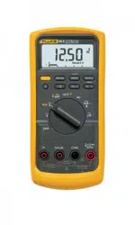
80 Series V
Digital Multimeter
Calibration Manual
PN 2102915
September 2004, Rev.1, 2/05
© 2004-2005 Fluke Corporation, All rights reserved. Printed in USA
All product names are trademarks of their respective companies.
1.888.610.7664 sales@GlobalTestSupply.com
Fluke-Direct.com

Lifetime Limited Warranty
Each Fluke 20, 70, 80, 170 and 180 Series DMM will be free from defects in material and workmanship for
its lifetime. As used herein, “lifetime” is defined as seven years after Fluke discontinues manufacturing the
product, but the warranty period shall be at least ten years from the date of purchase. This warranty does
not cover fuses, disposable batteries, damage from neglect, misuse, contamination, alteration, accident or
abnormal conditions of operation or handling, including failures caused by use outside of the product’s
specifications, or normal wear and tear of mechanical components. This warranty covers the original
purchaser only and is not transferable.
For ten years from the date of purchase, this warranty also covers the LCD. Thereafter, for the lifetime of
the DMM, Fluke will replace the LCD for a fee based on then current component acquisition costs.
To establish original ownership and prove date of purchase, please complete and return the registration
card accompanying the product, or register your product on. Fluke will, at its option, repair at no charge,
replace or refund the purchase price of a defective product purchased through a Fluke authorized sales
outlet and at the applicable international price. Fluke reserves the right to charge for importation costs of
repair/replacement parts if the product purchased in one country is sent for repair elsewhere.
If the product is defective, contact your nearest Fluke authorized service center to obtain return authorization
information, then send the product to that service center, with a description of the difficulty, postage and
insurance prepaid (FOB Destination). Fluke assumes no risk for damage in transit. Fluke will pay return
transportation for product repaired or replaced in-warranty. Before making any non-warranty repair, Fluke
will estimate cost and obtain authorization, then invoice you for repair and return transportation.
THIS WARRANTY IS YOUR ONLY REMEDY. NO OTHER WARRANTIES, SUCH AS FITNESS FOR A
PARTICULAR PURPOSE, ARE EXPRESSED OR IMPLIED. FLUKE SHALL NOT BE LIABLE FOR ANY
SPECIAL, INDIRECT, INCIDENTAL OR CONSEQUENTIAL DAMAGES OR LOSSES, INCLUDING LOSS
OF DATA, ARISING FROM ANY CAUSE OR THEORY. AUTHORIZED RESELLERS ARE NOT
AUTHORIZED TO EXTEND ANY DIFFERENT WARRANTY ON FLUKE’S BEHALF. Since some states do
not allow the exclusion or limitation of an implied warranty or of incidental or consequential damages, this
limitation of liability may not apply to you. If any provision of this warranty is held invalid or unenforceable by
a court or other decision-maker of competent jurisdiction, such holding will not affect the validity or
enforceability of any other provision.
2/02
1.888.610.7664 sales@GlobalTestSupply.com
Fluke-Direct.com

i
Table of Contents
Title Page
Introduction
........................................................................................................ 1
Contacting Fluke................................................................................................ 1
Precautions and Safety Information................................................................... 2
Electrical Symbols ............................................................................................. 4
Specifications..................................................................................................... 4
General Specifications................................................................................... 4
Detailed Specifications.................................................................................. 5
Basic Maintenance............................................................................................. 9
Cleaning the Meter ........................................................................................ 9
Opening the Meter Case ................................................................................ 9
Accessing the PCA and Replacing the LCD ................................................. 10
Reassembling the Meter Case........................................................................ 11
Replacing the Battery .................................................................................... 12
Testing Fuses and Current Circuitry.............................................................. 12
Replacing the Fuses....................................................................................... 13
Required Equipment .......................................................................................... 13
Performance Tests.............................................................................................. 14
Basic Operability Tests.................................................................................. 15
Testing the Fuses ........................................................................................... 15
Testing the Display........................................................................................ 15
Testing the Pushbuttons................................................................................. 17
Testing Meter Accuracy ................................................................................ 17
Testing the Inductive Pickup (88 Only) ........................................................ 19
Calibration Adjustment...................................................................................... 23
Calibration Adjustment Counter.................................................................... 23
Calibration Adjustment Password ................................................................. 23
Changing the Password ............................................................................. 23
Restoring the Default Password ................................................................ 24
Meter Buttons Used in the Calibration Steps ................................................ 25
Calibration Adjustment Procedure ................................................................ 25
Service and Parts................................................................................................ 27
1.888.610.7664 sales@GlobalTestSupply.com
Fluke-Direct.com

iii
List of Tables
Table Title Page
1. Electrical
Symbols ................................................................................................. 4
2.
Model 87 AC Voltage Function Specifications ..................................................... 5
3. Models 83 and 88 AC Voltage Function Specifications ........................................ 5
4. DC Voltage, Resistance, and Conductance Function Specifications ..................... 6
5. Temperature Specifications (87 and 88 Only) ....................................................... 6
6. Current Function Specifications............................................................................. 6
7. Capacitance and Diode Function Specifications .................................................... 7
8. Frequency Counter Specifications (Models 87 and 83) ......................................... 7
9. Frequency Counter Specifications (Model 88) ...................................................... 7
10. Frequency Counter Sensitivity and Trigger Levels................................................ 7
11. Electrical Characteristics of the Terminals............................................................. 8
12. MIN MAX Recording Specifications .................................................................... 8
13. Required Tools and Equipment.............................................................................. 14
14. Display Features..................................................................................................... 15
15. Accuracy Tests ....................................................................................................... 17
16. Calibration Adjustment Steps................................................................................. 26
17. 80 Series V Final Assembly ................................................................................... 27
1.888.610.7664 sales@GlobalTestSupply.com
Fluke-Direct.com

v
List of Figures
Figure Title Page
1. Opening the Meter, Battery and Fuse Replacement............................................... 10
2.
Removing LCD Mask to Access LCD................................................................... 11
3. Testing the Current Input Fuses ............................................................................. 13
4. Display Features..................................................................................................... 15
5. Setup for Inductive Pickup Test............................................................................. 21
6. Waveform for Inductive Pickup Test ..................................................................... 22
7. Restoring the Default Password ............................................................................ 24
8. 80 Series V Final Assembly ................................................................................... 28
1.888.610.7664 sales@GlobalTestSupply.com
Fluke-Direct.com

1
Introduction
XW Warning
To avoid shock or injury:
•
Read “Precautions and Safety Information” before
performing the verification tests or calibration adjustment
procedures documented in this manual.
• Do not perform the verification tests or calibration
adjustment procedures described in this manual unless you
are qualified to do so.
• The information provided in this manual is for the use of
qualified personnel only.
WCaution
•
The 80 Series V Digital Multimeters contains parts that can
be damaged by static discharge.
• Follow the standard practices for handling static sensitive
devices.
The 80 Series V Calibration M
anual provides the following information:
• Safety inform
ation
• Specifications
• Basic m
aintenance (cleaning, replacing the battery
and fuses)
• Performance test procedures
• Calibration adjustm
e
nt procedures
• Replaceable parts
For com
plete operating instructions, refer to the 80 Series V or 88 Series V Users
Manual.
1.888.610.7664 sales@GlobalTestSupply.com
Fluke-Direct.com

80 Series V
Calibration Manual
2
XWWarning
To avoid possible electric shock or personal injury, inspect the
test leads for damaged insulation or exposed metal. Check the
test leads for continuity. Replace damaged test leads before
using the Meter.
Precautions and Safety Information
In this manual, a Warning identifies conditions and actions that pose hazard(s) to the
user; a Caution identifies conditions and actions that may damage the Meter or the test
instruments.
XWWarning
To avoid possible electric shock or personal injury, follow these
guidelines:
•
Use this Meter only as specified in this manual or the
protection provided by the Meter might be impaired.
• Do not use the Meter if it is damaged. Before using the
Meter, inspect the case. Look for cracks or missing plastic.
Pay particular attention to the insulation surrounding the
connectors.
• Make sure the battery door is closed and latched before
operating the Meter.
• Replace the battery as soon as the battery indicator (M)
appears.
• Remove test leads from the Meter before opening the
battery door.
• Inspect the test leads for damaged insulation or exposed
metal. Check the test leads for continuity. Replace damaged
test leads before using the Meter.
• Do not apply more than the rated voltage, as marked on the
Meter, between the terminals or between any terminal and
earth ground.
• Never operate the Meter with the cover removed or the case
open.
• Use caution when working with voltages above 30 V ac rms,
42 V ac peak, or 60 V dc. These voltages pose a shock
hazard.
• Use only the replacement fuses specified in this manual.
• Use the proper terminals, function, and range for
measurements.
• Avoid working alone.
• When measuring current, turn off circuit power before
connecting the Meter in the circuit. Remember to place the
Meter in series with the circuit.
1.888.610.7664 sales@GlobalTestSupply.com
Fluke-Direct.com

Digital Multimeter
Precautions and Safety Information
3
• When making electrical connections, connect the common
test lead before connecting the live test lead; when
disconnecting, disconnect the live test lead before
disconnecting the common test lead.
• Do not use the Meter if it operates abnormally. Protection
may be impaired. When in doubt, have the Meter serviced.
• Do not operate the Meter around explosive gas, vapor, or
dust.
•
Use only a single 9 V battery, properly installed in the Meter
case, to power the Meter.
• When servicing the Meter, use only specified replacement
parts.
• When using probes, keep fingers behind the finger guards
on the probes.
• Do not use the Low Pass Filter option to verify the presence
of hazardous voltages. Voltages greater than what is
indicated may be present. Make a voltage measurement
without the filter to detect the possible presence of
hazardous voltage, then select the filter function.
XCaution
To avoid possible damage to the Meter or to the equipment
under test, follow these guidelines:
•
Disconnect circuit power and discharge all high-voltage
capacitors before testing resistance, continuity, diodes, or
capacitance.
• Before measuring current, check the Meter's fuses.
See " Testing the Fuses”.
1.888.610.7664 sales@GlobalTestSupply.com
Fluke-Direct.com
80 Series V
Calibration Manual
4
Electrical Symbols
Electrical symbols used on the Meter and in this manual are explained in Table 1.
Table 1. Electrical Symbols
B
AC (Alternating Current)
J
Earth ground
F
DC (Direct Current)
I
Fuse
X
Hazardous voltage.
P
Conforms to European Union directives
W
Risk of Danger. Important
information. See Manual.
$
Conforms to relevant Canadian
Standards Association directives
M
Battery
T
Double insulated
R
Continuity test or continuity beeper
tone.
E
Capacitance
t
Underwriters Laboratories
G
Diode
CAT III
IEC overvoltage category III
CAT III equipment is designed to
protect against transients in
equipment in fixed-equipment
installations, such as distribution
panels, feeders and short branch
circuits, and lighting systems in
large buildings.
CAT IV
IEC overvoltage category IV
CAT IV equipment is designed to protect
against transients from the primary
supply level, such as an electricity meter
or an overhead or underground utility
service.
s
Inspected and licensed by TÜV Product Services.
Specifications
General Specifications
Maximum Voltage between any Terminal and Earth Ground: 1000 V rms
W Fuse Protection for mA or µA inputs: 44/100 A, 1000 V FAST Fuse
W Fuse Protection for A input: 11 A, 1000 V FAST Fuse
Display: Digital: 6000 counts updates 4/sec; (Model 87 and 88 also has 19,999 counts in high-resolution mode).
Analog Bargraph: 33 segments, updates 40/sec. Frequency: 19,999 counts, updates 3/sec at > 10 Hz
Temperature: Operating: -20 °C to +55 °C; Storage: -40 °C to +60 °C
Altitude: Operating: 2000 m; Storage: 10,000 m
Temperature Coefficient: 0.05 x (specified accuracy)/ °C (< 18 °C or > 28 °C)
Electromagnetic Compatibility:
In an RF field of 3 V/m total accuracy = specified accuracy + 20 counts
Except: 600 µA dc range total accuracy=specified accuracy + 60 counts.
Temperature not specified.
Relative Humidity: 0 % to 90 % (0 °C to 35 °C); 0 % to 7 0% (35 °C to 55 °C)
Battery Type: 9 V zinc, NEDA 1604 or 6F22 or 006P
Battery Life: 400 hrs typical with alkaline battery (with backlight off)
Vibration: Per MIL-PRF-28800 for a Class 2 instrument
Shock: 1 Meter drop per IEC 61010-1:2001
Size (HxWxL): 1.25 in x 3.41 in x 7.35 in (3.1 cm x 8.6 cm x 18.6 cm)
Size with Holster and Flex-Stand: 2.06 in x 3.86 in x 7.93 in (5.2 cm x 9.8 cm x 20.1 cm)
Weight: 12.5 oz (355 g)
Weight with Holster and Flex-Stand: 22.0 oz (624 g)
Safety: Complies with ANSI/ISA S82.01-2004, CSA 22.2 No. 1010.1:2004 to 1000 V Overvoltage Category III, IEC
1.888.610.7664 sales@GlobalTestSupply.com
Fluke-Direct.com
Digital Multimeter
Specifications
5
664 to 600 V Overvoltage Category IV. UL listed to UL61010-1. Licensed by TÜV to EN61010-1.
Detailed Specifications
For all detailed specifications:
Accuracy is given as ±([% of reading] + [number of least significant digits]) at 18° C to
28° C, with relative humidity up to 90 %, for a period of one year after calibration.
For Model 87 in the 4 ½-digit mode, multiply the number of least significant digits
(counts) by 10. AC conversions are ac-coupled and valid from 3 % to 100 % of range.
Model 87 is true rms responding. AC crest factor can be up to 3 at full scale, 6 at half
scale. For non-sinusoidal wave forms add -(2 % Rdg + 2 % full scale) typical, for a crest
factor up to 3.
Table 2. Model 87 AC Voltage Function Specifications
Function Range Resolution Accuracy
45 - 65 Hz
30 - 200 Hz 200 - 440 Hz
440 Hz -
1 kHz
1 - 5 kHz 5 - 20 kHz
1
± (0.7 % + 4)
± (0.7 % + 2)
± (2.0 % + 4) ± (2.0 % + 20)600.0 mV
6.000 V
60.00 V
600.0 V
0.1 mV
0.001 V
0.01 V
0.1 V
± (2.0 % + 4)
3
unspecified
1000 V 1 V
± (1.0 % + 4)
unspecified unspecified
K
2,4
Low pass filter ± (0.7 % +
2) ± (1.0 % + 4)
+1 % + 4
-6 % - 4
5
unspecified
unspecified unspecified
1. Below 10 % of range, add 12 counts.
2.
The Meter is a true rms responding meter. When the input leads are shorted together in the ac functions, the Meter
may display a residual reading between 1 and 30 counts. A 30 count residual reading will cause only a 2-digit
change for readings over 3 % of range. Using REL to offset this reading may produce a much larger constant error
in later measurements.
3.
Frequency range: 1 kHz to 2.5 kHz.
4. A res
idual reading of up to 13 digits with leads shorted, will not affect stated accuracy abov
e 3 % of range.
5. Specification increases from -1% at 200 Hz to -6% at 440 Hz when filter is in use.
Table 3. Models 83 and 88 AC Voltage Function Specifications
Function Range Resolution Accuracy
50 Hz - 60 Hz
30 Hz - 1 kHz 1 kHz - 5 kHz
K
1
600.0 mV
6.000 V
60.00 V
600.0 V
1000 V
0.1 mV
0.001 V
0.01 V
0.1 V
1 V
± (0.5 % + 4)
± (0.5 % + 2)
± (0.5 % + 2)
± (0.5 % + 2)
± (0.5 % + 2)
± (1.0 % + 4)
± (1.0 % + 4)
± (1.0 % + 4)
± (1.0 % + 4)
± (1.0 % + 4)
± (2.0 % + 4)
± (2.0 % + 4)
± (2.0 % + 4)
± (2.0 % + 4)
2
unspecified
1. Below a reading of 200 counts, add 10 counts.
2. Frequency range: 1 kHz to 2.5 kHz.
For models 83 and 88, ac conversions are ac-coupled and are average- responding, rms-indicating.
1.888.610.7664 sales@GlobalTestSupply.com
Fluke-Direct.com
80 Series V
Calibration Manual
6
Table 4. DC Voltage, Resistance, and Conductance Function Specifications
Accuracy
Function Range Resolution
Model 83
Model 87 Model 88
L
6.000 V
60.00 V
600.0 V
1000 V
0.001 V
0.01 V
0.1 V
1 V
± (0.1 % + 1)
± (0.1 % + 1)
± (0.1 % + 1)
± (0.1 % + 1)
± (0.05 % + 1)
± (0.05 % + 1)
± (0.05 % + 1)
± (0.05 % + 1)
± (0.1 % + 1)
± (0.1 % + 1)
± (0.1 % + 1)
± (0.1 % + 1)
F
mV
600.0 mV 0.1 mV ± (0.3 % + 1) ± (0.1 % + 1) ± (0.3 % + 1)
e
nS
600.0 Ω
6.000 kΩ
60.00 kΩ
600.0 kΩ
6.000 MΩ
50.00 MΩ
60.00 nS
0.1 Ω
0.001 kΩ
0.01 kΩ
0.1 kΩ
0.001 MΩ
0.01 MΩ
0.01 nS
± (0.4 % + 2)
1
± (0.4 % + 1)
± (0.4 % + 1)
± (0.7 % + 1)
± (0.7 % + 1)
± (1.0 % + 3)
2
± (1.0 % + 10)
1
± (0.2 % + 2)
1
± (0.2 % + 1)
± (0.2 % + 1)
± (0.6 % + 1)
± (0.6 % + 1)
± (1.0 % + 3)
2
± (1.0 % + 10)
1
± (0.4 % + 2)
1
± (0.4 % + 1)
± (0.4 % + 1)
± (0.7 % + 1)
± (0.7 % + 1)
± (1.0 % + 3)
2
± (1.0 % + 10)
1
1. When using the REL ∆ function to compensate for offsets.
2. Add 0.5 % of reading when measuring above 30 MΩ in the 50 MΩ range, and 20 counts below 33 nS in the 60
nS range.
Table 5. Temperature Specifications (87 and 88 Only)
Temperature Resolution Accuracy
1,2
-200 °C to +1090 °C
-328 °F to +1994 °F
0.1 °C
0.1 °F
1 % + 10
1 % + 18
1. Does not include error of the thermocouple probe.
2. A
ccuracy specification assumes ambient temperature stable to
± 1 °C. For ambient temperature changes of ± 5 °C,
rated accuracy applies after 1 hour.
Table 6. Current Function Specifications
Accuracy
Function Range Resolution
Model 83
1
Model 87
2, 3
Model 88
1
Burden
Voltage
(typical)
mA
\
(45 Hz to
2 kHz)
mA
[
60.00 mA
400.0 mA
6
6.000 A
10.00 A
4
60.00 mA
400.0 mA
6
6.000 A
10.00 A
4
0.01 mA
0.1 mA
0.001 A
0.01 A
0.01 mA
0.1 mA
0.001 A
0.01 A
± (1.2 % + 2)
5
± (1.2 % + 2)
5
± (1.2 % + 2)
5
± (1.2 % + 2)
5
± (0.4 % + 4)
± (0.4 % + 2)
± (0.4 % + 4)
± (0.4 % + 2)
± (1.0 % + 2)
± (1.0 % + 2)
± (1.0 % + 2)
± (1.0 % + 2)
± (0.2 % + 4)
± (0.2 % + 2)
± (0.2 % + 4)
± (0.2 % + 2)
± (1.2 % + 2)
5
± (1.2 % + 2)
5
± (1.2 % + 2)
5
± (1.2 % + 2)
5
± (0.4 % + 4)
± (0.4 % + 2)
± (0.4 % + 4)
± (0.4 % + 2)
1.8 mV/mA
1.8 mV/mA
0.03 V/A
0.03 V/A
1.8 mV/mA
1.8 mV/mA
0.03 V/A
0.03 V/A
µA B
(45 Hz to
2 kHz)
µAF
600.0 µA
6000 µA
600.0 µA
6000 µA
0.1 µA
1 µA
0.1 µA
1 µA
± (1.2 % + 2)
5
± (1.2 % + 2)
5
± (0.4 % + 4)
± (0.4 % + 2)
± (1.0 % + 2)
± (1.0 % + 2)
± (0.2 % + 4)
± (0.2 % + 2)
± (1.2 % + 2)
5
± (1.2 % + 2)
5
± (0.4 % + 4)
± (0.4 % + 2)
100 µV/µA
100 µV/µA
100 µV/µA
100 µV/µA
1. AC conversion for Model 83 and 88 is ac coupled and calibrated to the rms value of a sine wave input.
2. AC conversions for Model 87 are ac coupled, true rms responding, and valid from 3 % to 100 % of range, except
400 mA range (5 % to 100 % of range) and 10 A range (15 % to 100 % or range).
3. Model 87 is a true rms responding meter. When the input leads are shorted together in the ac functions, the Meter
may
display a residual reading between 1 and 30 counts. A 30 count residual reading will cause only
a 2 digit
change for readings over 3 % of range. Using REL to offset this reading may produce a much larger constant
error in later measurements
4. W 10 A continuous up to 35 °C; < 20 minutes on, 5 minutes off at 35 °C to 55 °C. 20 A for 30 seconds maximum;
> 10 A unspecified.
5. Below a reading of 200 counts, add 10 counts.
6. 400 mA continuous; 600 mA for 18 hrs maximum.
1.888.610.7664 sales@GlobalTestSupply.com
Fluke-Direct.com
Digital Multimeter
Specifications
7
Table 7. Capacitance and Diode Function Specifications
Function Range Resolution Accuracy
E 10.00 nF
100.0 nF
1.000 µF
10.00 µF
100.0 µF
9999 µF
0.01 nF
0. 1 nF
0.001 µF
0.01 µF
0.1 µF
1 µ
F
± (1 % + 2)
1
± (1 % + 2)
1
± (1 % + 2)
± (1 % + 2)
± (1 % + 2)
± (1 % + 2)
G 3.000 V 0.001 V ± (2 % + 1)
1. With a film capacitor or better, using Relative mode to zero residual.
Table 8. Frequency Counter Specifications (Models 87 and 83)
Function Range Resolution Accuracy
Frequency
(0.5 Hz to 200 kHz,
pulse width > 2 µs)
199.99
1999.9
19.999 kHz
199.99 kHz
> 200 kHz
0.01 Hz
0.1 Hz
0.001 kHz
0.01 kHz
0.1 kHz
± (0.005 % + 1)
± (0.005 % + 1)
± (0.005 % + 1)
± (0.005 % + 1)
unspecified
Table 9. Frequency Counter Specifications (Model 88)
Function Range Resolution Accuracy
Pulse Width
Range (ms)
1
Resolution
(ms)
Frequency
2
(0.5 Hz to 200 kHz,
pulse width > 2 µs)
199.99
1999.9
19.999 kHz
199.99 kHz
> 200 kHz
0.01 Hz
0.1 Hz
0.001 kHz
0.01 kHz
0.1 kHz
± (0.01 % + 1)
± (0.01 % + 1)
± (0.01 % + 1)
± (0.01 % + 1)
unspecified
1999.9
5.00
0.500
0.0500
0.1
0.01
0.001
0.0001
RPM n 30 to 9,000 1 RPM ± 2 RPM
RPM o 60 to 12,000 1 RPM ± 2 RPM
% Duty Cycle
3
0.0 to 99.9% (0.5 Hz to 200 kHz, Pulse Width >2 µs)
Pulse Width
3
0.002 to 1999.9 ms (4 Hz to 200 kHz, Pulse Width >2 µs)
1. Pulse Width range is determined by the frequency of the signal.
2. Frequency measurements can be made on voltage or current inputs. The current inputs are always dc coupled.
3. For ri
se times >1 µs. Duty Cycle Accuracy: ±(0.2 % per kHz + 0.1%). Pulse Width Accuracy: ±
(0.002 ms + 3).
Table 10. Frequency Counter Sensitivity and Trigger Levels
Minimum Sensitivity (RMS Sine wave)
Input Range
1
5 Hz - 20 kHz 0.5 Hz - 200 kHz
Approximate Trigger Level
(DC Voltage Function)
600 mV dc
600 mV ac
6 V
60 V
600 V
1000 V
70 mV (to 400 Hz)
150 mV
0.3 V
3 V
30 V
100 V
70 mV (to 400 Hz)
150 mV
0.7 V
7 V (≤140 kHz)
70 V (≤14.0 kHz)
200 V (≤1.4 kHz)
40 mV
1.7 V
4 V
40 V
100 V
Duty Cycle Range Accuracy
0.0 to 99.9 % Within ± (0.2% per kHz + 0.1 %) for rise times < 1 µs.
1. Maximum input for specified accuracy = 10X Range or 1000 V.
1.888.610.7664 sales@GlobalTestSupply.com
Fluke-Direct.com
80 Series V
Calibration Manual
8
Table 11. Electrical Characteristics of the Terminals
Function
Overload
Protection
1
Input
Impedance
(nominal)
Common Mode
Rejection Ratio
(1 kΩ unbalance)
Normal Mode Rejection
L 1000 V rms 10 MΩ < 100 pF > 120 dB at dc,
50 Hz or 60 Hz
> 60 dB at 50 Hz or 60 Hz
F
mV
1000 V rms 10 MΩ < 100 pF > 120 dB at dc,
50 Hz or 60 Hz
> 60 dB at 50 Hz or 60 Hz
K 1000 V rms 10 MΩ < 100 pF
(ac-coupled)
> 60 dB, dc to 60 Hz
Full Scale Voltage Typical Short Circuit Current
Open Cir
cuit
Test Voltage
To 6.0 MΩ
50 MΩ or
60 nS
600 Ω 6 k 60 k 600 k 6 M 50 M
e 1000 V rms < 7.9 V dc < 4.1 V dc < 4.5 V dc 1 mA 100 µA 10 µA 1µA 1 µA 0.5 µA
G 1000 V rms < 3.9 V dc 3.000 V dc 0.6 mA typical
10
6
V Hz max
Table 12. MIN MAX Recording Specifications
Model Nominal Response Accuracy
83 100 ms to 80 % Specified accuracy ± 12 counts for changes > 200 ms in duration
(± 40 counts in ac with beeper on)
87, 88 100 ms to 80 %
(dc functions)
120 ms to 80 %
(ac functions)
250 µs (peak)
1
Specified accuracy ± 12 counts for changes > 200 ms in duration
Specified accuracy ± 40 counts for changes > 350 ms and inputs > 25 % of
range
Specified accuracy ± 100 counts for changes > 250 µs in duration
(add ± 100 counts for readings over 6000 counts)
(add ± 100 counts for readings in Low Pass mode)
1. For repetitive peaks: 1 ms for single events.
1.888.610.7664 sales@GlobalTestSupply.com
Fluke-Direct.com

Digital Multimeter
Basic Maintenance
9
Basic Maintenance
XWWarning
To avoid possible electric shock or personal injury:
•
Remove the test leads and any input signals before opening
the case or replacing the battery or fuses.
• Repairs or servicing covered in this manual should be
performed only by qualified personnel.
Cleaning the Meter
XWWarning
To avoid possible electric shock, personal injury, or damage to
the meter, never allow water inside the case.
WCaution
To avoid damaging the Meter, never apply abrasives, solvents,
aromatic hydrocarbons, chlorinated solvents, or methanol-
based fluids to the Meter.
Periodically wipe the Meter case with Fluke “MeterCleaner
TM
” or a damp cloth and mild
detergent.
Dirt or moisture in the A or mA µA input terminals can affect readings and can falsely
activate the Input Alert feature without the test leads being inserted. Such contamination
may be dislodged by turning the Meter over and, with all test leads removed, gently
tapping on the case.
Thoroughly clean the terminals as follows:
1. Turn the Meter off and rem
ove all test leads.
2. Soak a clean swab with isopropyl alcohol and work the swab around in each input
term
inal to remove contam
inates.
Opening the Meter Case
WCaution
To avoid unintended circuit shorting, always place the
uncovered Meter assembly on a protective surface. When the
case of the Meter is open, circuit connections are exposed.
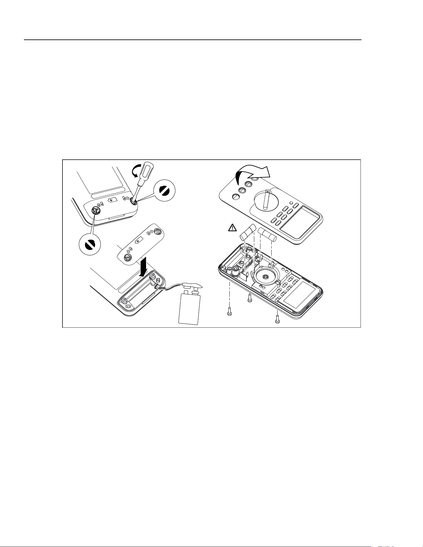
To open the Meter case, refer to Figure 1 and do the following:
1. Disconnect test leads from
any live source, turn the rotary knob to OFF, and rem
ove
the test leads from
the front term
inals.
2. Rem
ove the battery door by using a flat-blade screwdriver to turn the battery
door
screws 1/4-turn counterclockwise.
3. The case bottom
is secured to the case top by
three screws and two internal snaps (at
the LCD end). Using a Phillips-head screwdriver, remove the three screws.
1.888.610.7664 sales@GlobalTestSupply.com
Fluke-Direct.com
80 Series V
Calibration Manual
10
WCaution
To avoid damaging the Meter, the gasket that is sealed to the
bottom case, and is between the two case halves, must remain
with the case bottom. The case top lifts away from the gasket
easily. Do not damage the gasket or attempt to separate the
case bottom from the gasket.
4. Hold the Meter display
side up.
5. Pushing up from
the inside of the battery compartment, disengage the case top from
the gasket.
6. Gently
unsnap the case top at the display
end, see Figure 1.
F1
F2
ama12.eps
Figure 1. Opening the Meter, Battery and Fuse Replacement
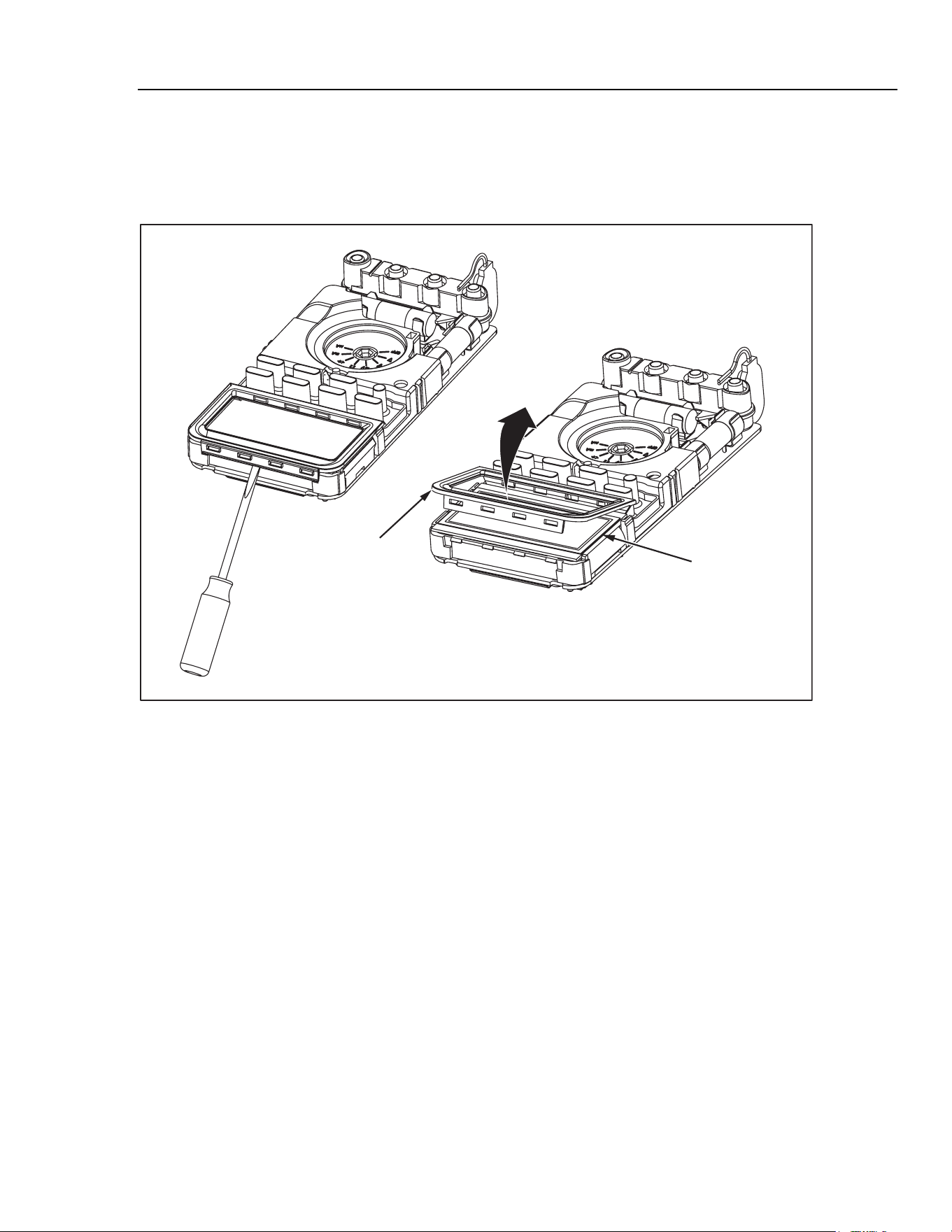
Accessing the PCA and Replacing the LCD
Once the case has been opened, the A1 Main PCA can easily be removed. The shields
disconnect from the PCA as follows:
1. Remove the five Phillips-head screw securing the top and bottom
shields to the PCA.
2. Rem
ove the top shield assembly
that also houses the LCD and lightpipe for the LCD
backlight.
3. To access the LCD, unsnap the LCD m
ask using a sm
all flat-blade screwdriver. The
LCD m
ay now be rem
oved. Refer to Figure 2.
Note
Two elastomeric connectors make electrical contact between the LCD and
the PCA. These connectors usually stick to the LCD when it is removed. If
the connectors are to be reused, do not handle them, as the electrical
contact points might become contaminated. Use tweezers to remove these
connectors.
4. To reinstall the connectors, replace the LCD and LCD m
ask and lay the top shield
face down. Install the elastomeric connector strips into the slots on the top shield.
1.888.610.7664 sales@GlobalTestSupply.com
Fluke-Direct.com
Digital Multimeter
Basic Maintenance
11
5. Place the PCA onto the top shield so that the screw holes align.
6. Place the bottom
shield onto the PCA and secure the assembly
with five Phillips-head
screws. Ensure that the shields are tightly
attached. Properly
fitted shields are
required for the Meter to perform to specifications.
LCD
LCD Mask
ama08f.eps
Figure 2. Removing LCD Mask to Access LCD
Reassembling the Meter Case
To reassemble the Meter case:
1. Verify that the rotary knob and circuit board switch are in the
OFF position, and that
the gasket rem
ains secured to the bottom
case.
2. Place the PCA into the bottom case.
3. Place the case top on the case bottom
.
4. To avoid damaging the battery wire, ensure the wire exits the middle of the battery
compartm
ent.
5. Properly
seat the case gasket and snap the
case halves together above the LCD end.
See Figure 1.
6. Reinstall the three case screws and the battery door.
7. Secure the battery
door by
turning the screw 1/4-turn clockwise.
8. Go to “Perform
ance Tests” later in this document, and perform
the procedures
described.
1.888.610.7664 sales@GlobalTestSupply.com
Fluke-Direct.com

80 Series V
Calibration Manual
12
Replacing the Battery
Replace the battery with a 9-V battery (NEDA A1604, 6F22, or 006P).
XWWarning
To avoid false readings, which could lead to possible electric
shock or personal injury, replace the battery as soon as the
battery indicator (b) appears. If the display shows “bAtt”
the
Meter will not function until the battery is replaced.
Replace the battery
as follows, refer to Figure 1:
1. Turn the rotary knob to OFF and remove the test leads from the term
inals.
2. Rem
ove the battery door by using a standard-blade screwdriver to turn the battery
door screws one-quarter turn counterclockwise.
3. Rem
ove the old battery
and replace it with a new one.
4. Align the battery
leads so that they not pinched between the battery
door and the case
bottom
.
5. Secure the door by
turning the screws one-quarter turn clockwise.
Testing Fuses and Current Circuitry
If a test lead is plugged into the mA/µA or A term
inal and the rotary knob is turned to a
non-current function, the Meter chirps and flashes “LEAd” if the fuse associated with that
current terminal is good. If the Meter does not chirp or flash “LEAd”, the fuse is bad and
must be replaced. Refer to Table 17 for the appropriate replacement fuse.
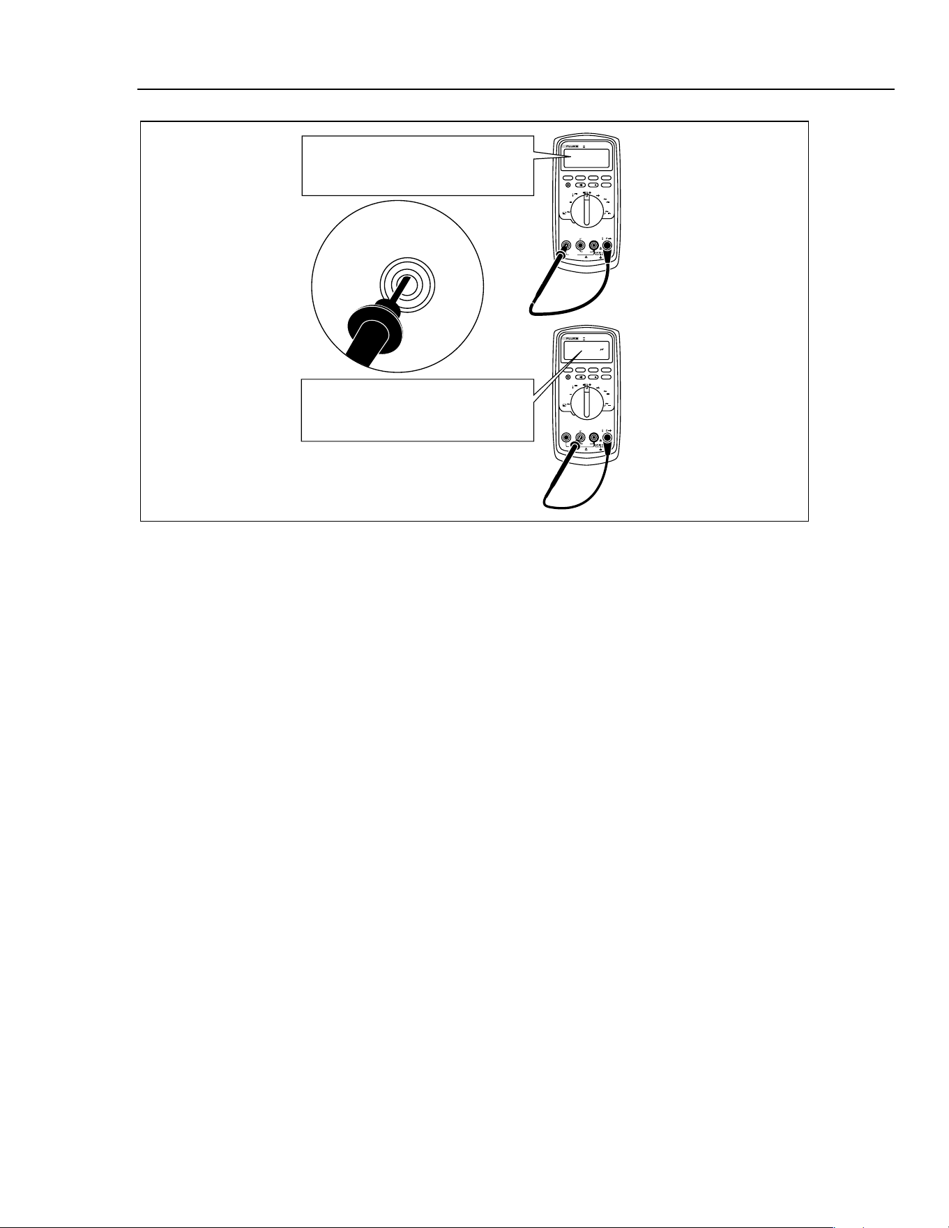
After replacing the fuse, use the following procedure to verify the integrity of the new
fuse and the current circuitry. Refer to Figure 3.
1. Turn the rotary knob to N
.
2. To test F2, insert a test lead into the I input terminal and touch the probe to
the A input terminal.
Note
The input receptacles contain split contacts. Be sure to touch the probe to
the half of the receptacle nearest the LCD.
3. The display
should indicate between 00.0 Ω and 00.5 Ω. If the display
reads OL,
replace the fuse and test again. If the display reads another value, further servicing is
required.
4. To test F1, m
ove the probe from the A input terminal to the mA/UA input term
inal.
5. The display
should read between 0.995 kΩ and 1.005 kΩ. If the display
reads OL,
replace the fuse and test again. If the display reads another value, further servicing is
required.
XWWarning
To avoid electrical shock or personal injury:
•
Remove the test leads and any input signals before
replacing the battery or fuses.
• Install ONLY specified replacement fuses with the
amperage, voltage, and speed ratings shown in Table 17.
1.888.610.7664 sales@GlobalTestSupply.com
Fluke-Direct.com
Digital Multimeter
Required Equipment
13
MIN MAX
RANGE
REL
Hz %
AutoHOLD
Peak MIN MAX
4½ DIGITS
1 Second
˚
C/
˚
F
OFF
mA
A
mV
V
V
A
A
mA
COM
V
400mA
FUSED
10A MAX
FUSED
A
TRUE RMS MULTIMETER
87
V
LOLO
MIN MAX
RANGE
REL
Hz %
AutoHOLD
Peak MIN MAX
4½ DIGITS
1 Second
˚
C/
˚
F
OFF
mA
A
mV
V
V
A
A
mA
COM
V
400mA
FUSED
10A MAX
FUSED
A
TRUE RMS MULTIMETER
87
V
LOLO
Good F2 fuse: 00.0 Ω to
00.5 Ω
Good F1 fuse: 0.995 kΩ to
1.005 kΩ
Replace fuse: OL
Replace fuse: OL
Touch top half
of input contacts
aom5f.eps
Figure 3. Testing the Current Input Fuses
Replacing the Fuses
To replace the fuse(s), perform the following procedure.
1.
To open the Meter, refer to “Opening the Meter Case”. See Figure 1.
2. Grasp the fuse in the center with needle nose pliers. Pull straight up on the fuse to
rem
ove it from
the fuse clips.
3. Install ONLY specified replacem
ent fuses with the am
perage, voltage, and speed
ratings shown in Table 17.
4. To close the Meter, refer to “Reassembling the Meter Case”.
Required Equipment
Required equipment for the performance tests is listed in Table 13. If the recommended
models are not available, equipment with equivalent specifications may be used.
XW Warning
• To avoid shock or injury, do not perform the verification
tests or calibration adjustment procedures described in this
manual unless you are qualified to do so.
• Repairs or servicing should be performed only by qualified
personnel.
1.888.610.7664 sales@GlobalTestSupply.com
Fluke-Direct.com

80 Series V
Calibration Manual
14
Table 13. Required Equipment
Equipment Required Characteristics Recommended Model
Calibrator AC Voltage Range: 0 - 1000 V ac
Accuracy: ± 0.12 %
Frequency Range: 60 - 20000 Hz
Accuracy: ± 3 %
DC Voltage Range: 0 - 1000 V dc
Accuracy: ± 0.012 %
Current Range: 350 µA - 2 A
Accuracy: AC (60 Hz to 1 kHz): ± 0.25 %
DC: ± 0.05 %
Frequency Source: 19.999 kHz - 199.99 kHz
Accuracy: ± 0.0025 %
Amplitude: 150 mV to 6V rms
Accuracy: ± 5 %
Fluke 5520A Multi-Product
Calibrator or equivalent
Range: 1 Ω - 100 MΩ
Accuracy: 0.065 %
Function Generator Frequency = 900 kHz
Amplitude = 8.3V
Burst mode = 1
Burst rate = 100Hz
Burst Phase = -90 degrees
HP33120
Fluke 80 AK
TC Adapter Accessory
K-type Fluke 80 AK
K-type Thermocouple K-type, mini-plug on both ends
Performance Tests
The following performance tests verify the complete operability of the Meter and check
the accuracy of each Meter function against the Meter’s specifications. Performance tests
should be performed annually to ensure that the Meter is within accuracy specifications.
Accuracy specifications are valid for a period of one year after calibration adjustment,
when measured at an operating temperature of 18 °C to 28 °C and at a maximum of 90 %
relative humidity.
To perform the following tests, it is not necessary to open the case. No adjustments are
necessary. Make the required connections, apply the designated inputs, and determine if
the reading on the Meter display falls within the acceptable range indicated.
Note
If the Meter fails any of these tests, it needs calibration adjustment or repair.
1.888.610.7664 sales@GlobalTestSupply.com
Fluke-Direct.com
Digital Multimeter
Performance Tests
15
Basic Operability Tests
Refer to the following sections to test the basic operability of the Meter.
Testing the Fuses
Refer to “Testing the Fuses”.
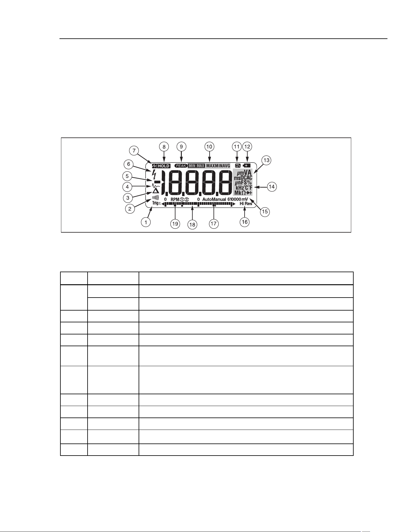
Testing the Display
Turn the Meter on while holding down D to view all segments of the display.
Compare the display with the appropriate examples in Figure 4 and Table 14.
ayi04.eps
Figure 4. Display Features
Table 14. Display Features
Number Feature Indication
Y
Polarity indicator for the analog bar graph.
A
TrigY
Positive or negative slope indicator for Hz/duty cycle triggering.
B X
The continuity beeper is on.
C W
Relative (REL) mode is active.
D g
Smoothing is active.
E
-
Indicates negative readings. In relative mode, this sign indicates that the
present input is less than the stored reference.
F
Z
Indicates the presence of a high voltage input. Appears if the input voltage is
30 V or greater (ac or dc). Also appears in low pass filter mode. Also appears
in cal, Hz, and duty cycle modes.
G
RS
AutoHOLD is active.
H
S
Display Hold is active.
I
p
Indicates the Meter is in Peak Min Max mode and the response time is 250 µs
J
m MAX
MIN AVG
Indicators for minimum-maximum recording mode.
K
K
Low pass filter mode.
1.888.610.7664 sales@GlobalTestSupply.com
Fluke-Direct.com
80 Series V
Calibration Manual
16
Table 13. Display Features (cont.)
Number Feature Indication
L
b
The battery is low. XWWarning: To avoid false readings, which could lead to
possible electric shock or personal injury, replace the battery as soon as the
battery indicator appears.
M
A, µA, mA
Amperes (amps), Microamp, Milliamp
V, mV
Volts, Millivolts
µF, nF
Microfarad, Nanofarad
nS
Nanosiemens
%
Percent. Used for duty cycle measurements.
e, Me, ke
Ohm, Megohm, Kilohm
Hz, kHz
Hertz, Kilohertz
AC DC
Alternating current, direct current
N
°C, °F
Degrees Celsius, Degrees Fahrenheit
O
610000 mV
Displays selected range
P
HiRes
The Meter is in high resolution
(Hi Res) mode. HiRes=19,999
Auto
The Meter is in autorange mode and automatically selects the range with the
best resolution.
Q
Manual
The Meter is in manual range mode.
R The number of segments is relative to the full-scale value of the selected
range. In normal operation 0 (zero) is on the left. The polarity indicator at the
left of the graph indicates the polarity of the input. The graph does not operate
with the capacitance, frequency counter functions, temperature, or peak min
max. For more information, see “Bar Graph”. The bar graph also has a zoom
function, as described under "Zoom Mode".
S
RPMon oconventional (4 cycle) Counts every other revolution.
nwaste spark of 2 cycle. Counts every revolution.
--
0L
Overload condition is detected.
Error Messages
bAtt
Replace the battery immediately.
diSC
In the capacitance function, too much electrical charge is present on the capacitor being tested.
EEPr
Err
Invalid EEPROM data. Have Meter serviced.
CAL
Err
Invalid calibration data. Calibrate Meter.
LEAd
WTest lead alert. Displayed when the test leads are in the A or mA/µA terminal and the selected
rotary switch position does not correspond to the terminal being used.
1.888.610.7664 sales@GlobalTestSupply.com
Fluke-Direct.com
Digital Multimeter
Performance Tests
17
Testing the Pushbuttons
To test the pushbuttons
1. Turn the Meter rotary knob to J
.
2. Press each button and note that the m
e
ter responds with a beep for each button
press.
3. Press and hold B a second tim
e to exit MIN MAX m
ode.
Testing Meter Accuracy
Perform
the accuracy test steps in Table 15.
Table 15. Accuracy Tests
Display Reading
Step
Test
Function
Range 5500A Output
83 and 88
87
1
600 mV 330 mV, 60 Hz 327.9 to 332.1 327.3 to 332.7
2
600 mV 600 mV, 13 kHz N/A 586.0 to 614.0
3
6 V 3.3 V, 60 Hz 3.281 to 3.319 3.275 to 3.325
4
6 V 3.3 V, 20 kHz N/A 3.214 to 3.386
5
60 V 33 V, 60 Hz 32.81 to 33.19 32.75 to 33.25
6
60 V 33 V, 20 kHz N/A 32.14 to 33.86
7
600 V 330 V, 60 Hz 328.1 to 331.9 327.5 to 332.5
8
600 V 330 V, 2.5 kHz N/A 323.0 to 337.0
9
1000 V 500 V, 60 Hz 495 to 505 494 to 506
10
K
AC Volts
1000 V 1000 V, 1 kHz 986 to 1014 986 to 1014
11
600 mV 150 mV, 99.95 kHz 99.93 to 99.97 99.93 to 99.97
12
K
Hz
AC Volts
Frequency
600 mV 150 mV, 199.50 kHz 199.48 to 199.52 199.48 to 199.52
13
6 V 0.7 V, 99.95 kHz 99.93 to 99.97 99.93 to 99.97
14
Sensitivity
60 V 7 V, 99.95 kHz 99.93 to 99.97 99.93 to 99.97
15
V Hz
Trigger level
6 V 3.4 V, 1 kHz Sq. Wave 999.8 to 1000.2 999.8 to 1000.2
16
V Hz
Duty Cycle
6 V 5 V, 1 kHz, DC offset 2.5 V
Sq. Wave
49.7% to 50.3 % 49.7 % to 50.3 %
17 6V 3.3 V dc
3.296 to 3.304
3.297 to 3.303
18 60 V 33 V dc
32.96 to 33.04
32.97 to 33.03
19 600 V 330 V dc
329.6 to 330.4
329.7 to 330.3
20
V
DC Volts
1000 V 1000 V dc
998 to 1002
998 to 1002
21 600 mV 33 mV dc
32.8 to 33.2
32.9 to 33.1
22
m
V
DC Volts
600 mV 330 mV dc
328.9 to 331.1
329.6 to 330.4
1.888.610.7664 sales@GlobalTestSupply.com
Fluke-Direct.com
80 Series V
Calibration Manual
18
Table 14. Accuracy Tests (cont.)
Display Reading
Step
Test
Function
Range 5500A Output
83 and 88 87
23 600 Ω 330 Ω ( Use 2 wire Comp)
1
328.5 to 331.5
329.1 to 330.9
24 6 kΩ 3.3 kΩ (Use 2 wire Comp)
1
3.286 to 3.314
3.292 to 3.308
25 60 kΩ 33 kΩ
32.86 to 33.14
32.92 to 33.08
26 600 kΩ 330 kΩ
327.6 to 332.4
327.9 to 332.1
27 6 MΩ 3.3 MΩ
3.276 to 3.324
3.279 to 3.321
28
e
Ohms
50 MΩ 30 MΩ
29.67 to 30.33
29.67 to 30.33
29
60 nS Open input - 0.30 to 0.30 - 0.30 to 0.30
30
nS
Conductance
60 nS 100 MΩ 9.60 to 10.40 9.60 to 10.40
31
G
Diode
6 V 3.0 V dc 2.939 to 3.061 2.939 to 3.061
32
?
AC Amps
6 A 3.0 A, 60 Hz 2.962 to 3.038 2.968 to 3.032
33
A
DC Amps
6 A 3.0 A 2.984 to 3.016 2.990 to 3.010
33B
A
DC Amps
10A
6
10A 9.94 to 10.06 9.96 to 10.04
34
60 mA 33 mA, 60 Hz 32.58 to 33.42 32.65 to 33.35
35
m
?
AC Milliamps
400 mA 330 mA, 60 Hz 325.8 to 334.2 326.5 to 333.5
36
60 mA 33 mA 32.83 to 33.17 32.89 to 33.11
37
m[
DC Milliamp
400 mA 330 mA 328.5 to 331.5 329.1 to 330.9
38
600 µA 330 µA, 60 Hz 325.8 to 334.2 326.5 to 333.5
39
U
?
AC
Microamps
6000 µA 3300 µA, 60 Hz
3258 to 3342 3265 to 3335
40
600 µA 330 µA 328.3 to 331.7 328.9 to 331.1
41
U[
DC
Microamps
6000 µA 3300 µA 3285 to 3315 3291 to 3309
42
10 nf Open input
2
0.21 to 0.31 0.21 to 0.31
43
100 nf 5 nf
5
04.7 to 05.3 04.7 to 05.3
44
E
Capacitance
100 µf 9.5 µf 09.2 to 09.8 09.2 to 09.8
45
1000 V 400 V, 400 Hz N/A 376 to 408
46
K
Low Pass
Filter
1000 V 400 V, 800 Hz
4
N/A 226 to 340
4
1.888.610.7664 sales@GlobalTestSupply.com
Fluke-Direct.com
Digital Multimeter
Performance Tests
19
Table 14. Accuracy Tests (cont.)
Display Reading
Step
Test
Function
Range 5500A Output
83 and 88 87
47
Max = 5.896 to 6.104
48
L
(87 and 88 only)
Peak Min/Max
6 V dc
8 Vpp, 2 kHz Sq.
Wave, DC offset 2 V
Min = -1.898 to -2.102
49
0 °C -1.0 to 1.0 -1.0 to 1.0
50
m
L
(87 and 88 only)
Temperature
3
100 °C 98.0 to 102.0 98.0 to 102.0
51
Press backlight button Backlight comes on
52
Press backlight button Backlight Intensifies
53
Backlight
Press backlight button Backlight off
1. Or short test leads and use REL to offset test lead resistance.
2. Remove test leads from unit.
3. To ensure accurate measurement, the Meter and thermocouple adapter must be at the same temperature. After
connecting the thermocouple adapter to the Meter allow for reading to stabalize before recording display reading.
4. The Meter accuracy is not specified at this input si
gnal frequency with Low-pass filter selected. The display reading
shown, check that the Low-pass filter
is active and follows an expected roll-off curve.
5. Use REL to compensate for internal Meter and l
ead capacitance. Test leads must be disconnected from the
calibrator before using REL.
6.
W 10 A continuous up to 35 °C; < 20 minutes on, 5 minutes off at 35 °C to 55 °C. 20 A for 30 seconds maximum;
> 10 A unspecified.
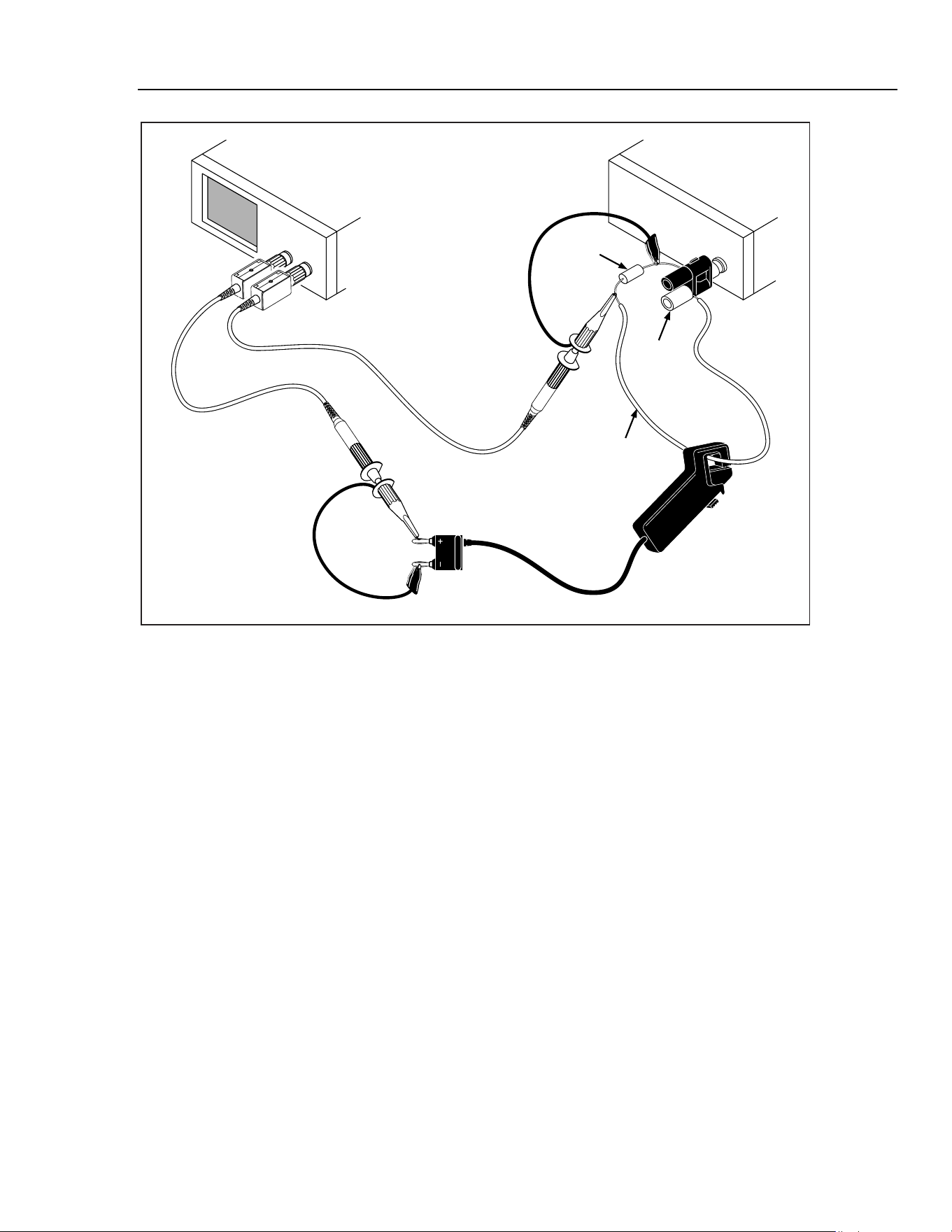
Testing the Inductive Pickup (88 Only)
To test the inductive pickup, a function generator output will simulate automobile spark
plug signals on a loop of wire containing a 10 e resistor. The pickup will be clamped to
the wire and output voltage from the pickup will be monitored by an oscilloscope.
Perform the following procedure to test the inductive pickup:
1. Solder a 10-inch piece of 14 AWG wire to one end of a 10 e
1 % resistor.
2. Connect the other end of the 10 e resistor to the terminal LOW output of the
function generator. Place the other end of the 14-AWG wire to the HIGH output of
the function generator. See Figure 5.
3. Connect a 10X scope probe from
channel 2
(dc-coupled) of the oscilloscope across
the 10 e resistor.
4. Clamp the inductive pickup to the wire loop on the HIGH side of the resistor as
shown in Figure 5.
Make sure that the jaws of the inductive pickup are closed com
pletely
, and that the
side of the inductive pickup that says "SPARK PLUG SIDE" points toward the
HIGH output of the function generator.
5. Connect a 10X scope probe from
channel 1
(dc-coupled) of the oscilloscope across
the output of the inductive pickup.
1.888.610.7664 sales@GlobalTestSupply.com
Fluke-Direct.com

80 Series V
Calibration Manual
20
6. Set up the function generator as follows:
Frequency
900 kHz
Am
plitude 8.3 V
Burst Mode
yes
Burst Count 1
Burst Rate 100 Hz
Burst Phase
-90 Degrees
7. Set the oscilloscope for 0.5 V/DIV @ 0.5 µs/DIV.
8. Trigger the waveform on channel 2.
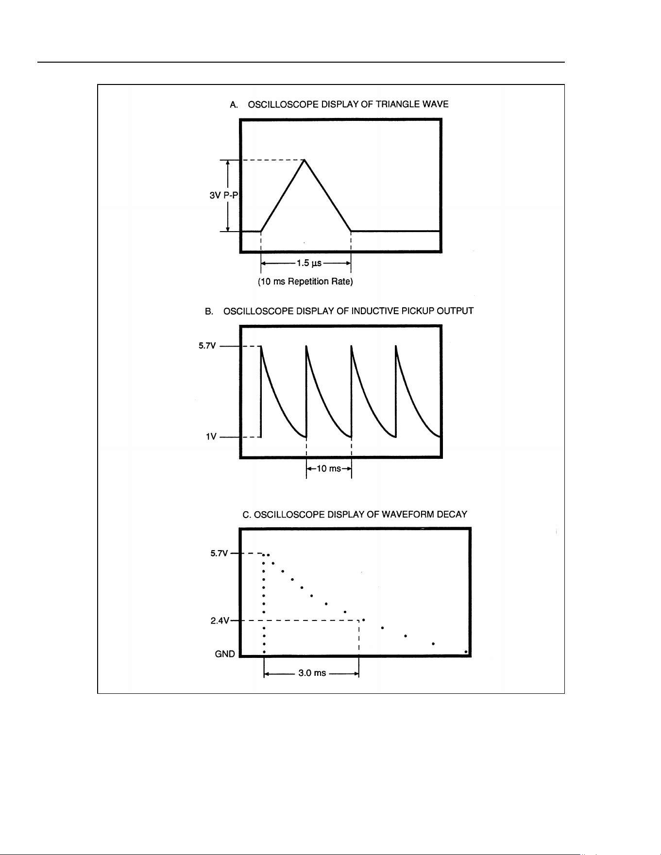
9. Adjust the amplitude of the function generator to produce a 3 VP-P triangle wave.
See Figure 6.
10. Set the oscilloscope for 1.0 V/DIV @ 5.0 m
s
/DIV.
11. Trigger the waveform on Channel 1.
12. Check that the peak voltage is greater than 5.7 V and decays to less than 1.0 V
between pulses. See Figure 6. Record
the peak value for later use.
13. Adjust the function generator output so the peak voltage is 6 V.
14. Set the scope for 1.0 m
s/DIV and trigger waveform
.
15. Check the am
plitude after 3.0 ms from the waveform peak, the voltage am
plitude is
2.4 V +0.5/-0.8 (1.6 V to 2.9 V). (See Figure 3-5(C).)
16.
Re-adjust the function generator output to obtain the value recorded in step 12.
17. Set the scope for 5.0 m
s
/DIV.
18. Turn the inductive pickup so that "SPARK PLUG SIDE" points along the wire
connected to the LOW output of the function generator. Check that the waveform is
less than 2 V.
1.888.610.7664 sales@GlobalTestSupply.com
Fluke-Direct.com
Digital Multimeter
Performance Tests
21
INDUCTIVE
PICKUP
SPARK PLUG SIDE
OSCILLOSCOPE
FUNCTION GENERATOR
CH1
CH2
10
RESISTOR
WIRE LOOP
(14 AWG)
OUTPUT
RED
aad08f.eps
Figure 5. Setup for Inductive Pickup Test
1.888.610.7664 sales@GlobalTestSupply.com
Fluke-Direct.com
80 Series V
Calibration Manual
22
aad09f.wmf
Figure 6. Waveform for Inductive Pickup Test
1.888.610.7664 sales@GlobalTestSupply.com
Fluke-Direct.com

Digital Multimeter
Calibration Adjustment
23
Calibration Adjustment
The Meter features closed-case calibration adjustment using known reference sources.
The Meter measures the applied reference source, calculates correction factors and stores
the correction factors in nonvolatile memory.
The following sections present the features and Meter pushbutton functions that can be
used during the Calibration Adjustment Procedure. Perform the Calibration Adjustment
Procedure should the Meter fail any performance test listed in Table 15.
Calibration Adjustment Counter
The Meter contains a calibration adjustment counter. The counter is incremented each
time a Calibration Adjustment Procedure is completed. The value in the counter can be
recorded and used to show that no adjustments have been made during a calibration
cycle.
Use the following steps to view the Meter's calibration counter.
1. While holding down B, turn the rotary knob from OFF to VAC
. The Meter
should display
“Z CAL
”.
2. Press D once to see the calibration counter. For example "n001".
3. Turn the rotary
knob to OFF
.
Calibration Adjustment Password
To start the Calibration Adjustm
ent Procedure, the correct 4-button password must be
entered. The password can be changed or reset to the default as described in following
paragraphs. The default password is “1234”.
Changing the Password
Use the following steps to change the Meter's password:
1. While holding down B, turn the rotary knob from OFF to VAC
. The Meter
display
s “Z CAL
”.
2. Press D once to see the calibration counter.
3. Press D again to start the password entry
. The Meter displays
"????".
4. The Meter buttons represent the digit indicated below when entering or changing the
password:
A = 1 B = 2 C = 3 D = 4
H = 5 E = 6 F = 7 G = 8
Press the 4 buttons to enter the old password. If changing the password for the first
tim
e, enter A (1) B (2) C (3) D
(4).
5. Press C to change the password. The Meter display
s
"----" if the old password is
correct. If the password is not correct, the Meter em
its a double beep, displays
"????"
and the password m
u
st be entered again. Repeat step 4.
6. Press the 4 buttons of the new password.
7. Press D to store the new password.
1.888.610.7664 sales@GlobalTestSupply.com
Fluke-Direct.com
80 Series V
Calibration Manual
24
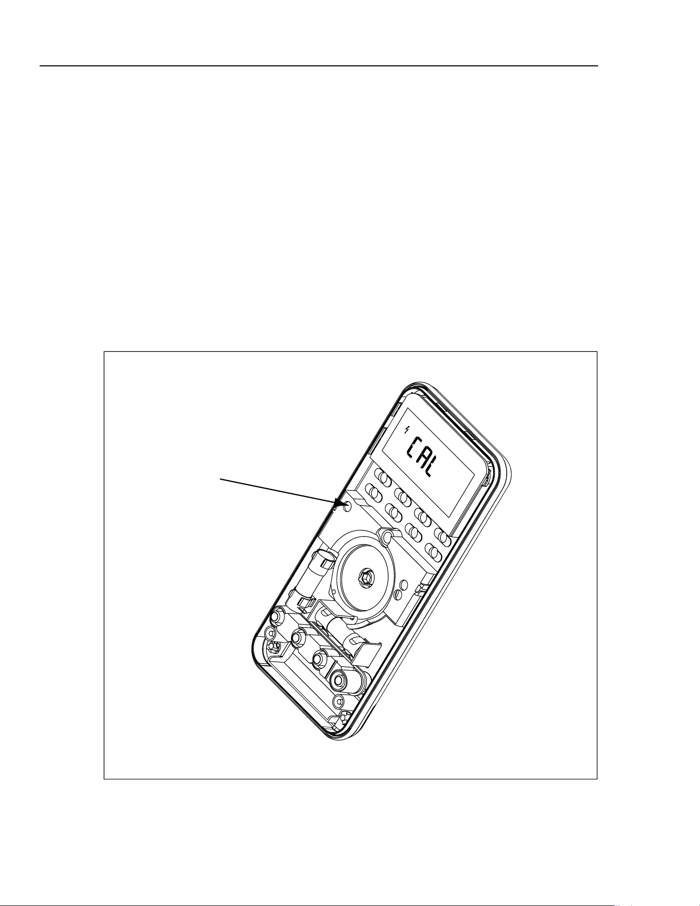
Restoring the Default Password
If the calibration password is forgotten, the default password (1234) can be restored using
the following steps.
1. While holding down B, turn the rotary knob from OFF to VAC
. The Meter
display
s “Z CAL
”.
2. Rem
ove the Meter's top case. Leave the PCA in the bottom
case. (See “Opening the
Meter Case”.)
XWWarning
To avoid electrical shock or personal injury, remove the test
leads and any input signal before removing the Meter's top
case.
3. Through an access hole provided in the top shield, short across the keyp
ads on the
PCA. See Figure 7. The Meter should beep. The default password is now restored.
4.
Replace the Meter'
s top case and turn the rotary knob to OFF. (See “Reassem
bling
the Meter Case).
Access Hole For
PCA Keypad
ama01f.eps
Figure 7. Restoring the Default Password
1.888.610.7664 sales@GlobalTestSupply.com
Fluke-Direct.com

Digital Multimeter
25
Meter Buttons Used in the Calibration Steps
The Meter buttons behave as follows when performing the Calibration Adjustment
Procedure. This may be of help determining why a calibration step is not accepted and for
determining the input value without referring to Table 16.
A
Press and hold to show the measured value. The measurement value is not
calibrated so it may not match the input value. This is normal.
B Press and hold to display the required input amplitude.
G Press and hold to display the frequency of the required input.
D
Press to store the calibration value and advance to the next step. This button
is also used to exit calibration mode after the calibration adjustment
sequence is complete.
Calibration Adjustment Procedure
Use the following steps to adjust the Meter's calibration. If the Meter is turned off before
completion of the adjustment procedure, the calibration constants are not changed.
1. While holding down B, turn the rotary knob from OFF to VAC
. The Meter
display
s “Z CAL
”.
2. Press D once to see the calibration counter.
3. Press D again to start the password entry. The Meter displays "????".
4. Press 4 buttons to enter the password.
5. Press D to go to the first calibration step. The Meter display
s
"C-01" if the
password is correct. If the password is not correct, the Meter emits a double beep,
display
s "????" and the password mu
st be entered again. Repeat step 4.
6. Using Table 16, apply
the input value listed for each calibration adjustme
nt step. For
each step, position the rotary
switch and apply the input to the term
inals as indicated
in the table.
7. After each input value is applied, press D to accept the value and proceed to the
next step (C-02 and so forth).
Notes
After pressing D, wait until the step number advances before changing
the calibrator source or turning the Meter rotary knob.
If the Meter rotary knob is not in the correct position, or if the measured
value is not within the anticipated range of the input value, the M
eter emits
a double beep and will not continue to the next step.
Some adjustment steps take longer to execute than others (10 to 15
seconds). For these steps, the Meter will beep when the step is complete.
Not all steps have this feature.
8. After the final step, the display
shows "End" to indicate that the calibration
adjustm
ent is complete. Press D to go to meter m
ode.
1.888.610.7664 sales@GlobalTestSupply.com
Fluke-Direct.com
80 Series V
Calibration Manual
26
Notes
Set the calibrator to Standby prior to changing the function switch position
and or after completing adjustment of each function.
If the calibration adjustment procedure is not completed correctly, the
Meter will not operate correctly.
Table 16. Calibration Adjustment Steps
Input Value
Function
(Switch Position)
Input Terminal
Adjustment
Step
Fluke 83-V and
88-V
Fluke 87-V
C-01 600.0 mV, 60 Hz 600.0 mV, 60 Hz
C-02 600.0 mV, 5 kHz 600.0 mV, 20 kHz
C-03 6.000 V, 60 Hz 6.000 V, 60 Hz
C-04 6.000 V, 5 kHz 6.000 V, 20 kHz
C-05 60.00 V, 60 Hz 60.00 V, 60 Hz
C-06 60.00 V, 5 kHz 60.00 V, 20 kHz
C-07 600.0 V, 60 Hz 600.0 V, 60 Hz
K
(AC Volts)
C-08 600.0 V, 5 kHz 600.0 V, 10 kHz
C-09 6.000 V 6.000 V
C-10 60.00 V 60.00 V
L
(DC Volts)
C-11 600.0 V 600.0 V
C-12 600.0 mV 600.0 mV
m
L
(DC Millivolts)
C-13 60.00 mV 60.00 mV
C-14 600.0 600.0
C-15 6.000 k 6.000 k
C-16 60.00 k 60.00 k
C-17 600.0 k 600.0 k
C-18 6.000 M 6.000 M
C-19 0.000 0.000
e
(Ohms)
C-20 50.0 M 50.0 M
O
(Diode Test)
I
C-21 3.000 V 3.000 V
C-22 6.000 A, 60 Hz 6.000 A, 60 Hz
A
(Amps)
A
C-23 6.000 A dc 6.000 A dc
C-24 60.00 mA, 60 Hz 60.00 mA, 60 Hz
C-25 400.0 mA, 60 Hz 400.0 mA, 60 Hz
C-26 60.00 mA dc 60.00 mA dc
mA
(Milliamps)
C-27 400.0 mA dc 400.0 mA dc
C-28
600.0 µA ac,
60 Hz
600.0 µA ac, 60 Hz
C-29 6000 µA, 60 Hz 6000 µA, 60 Hz
C-30 600.0 µA dc 600.0 µA dc
µA
(Microamps)
mA /UA
C-31 6000 µA dc 6000 µA dc
1.888.610.7664 sales@GlobalTestSupply.com
Fluke-Direct.com

Digital Multimeter
Service and Parts
27
Service and Parts
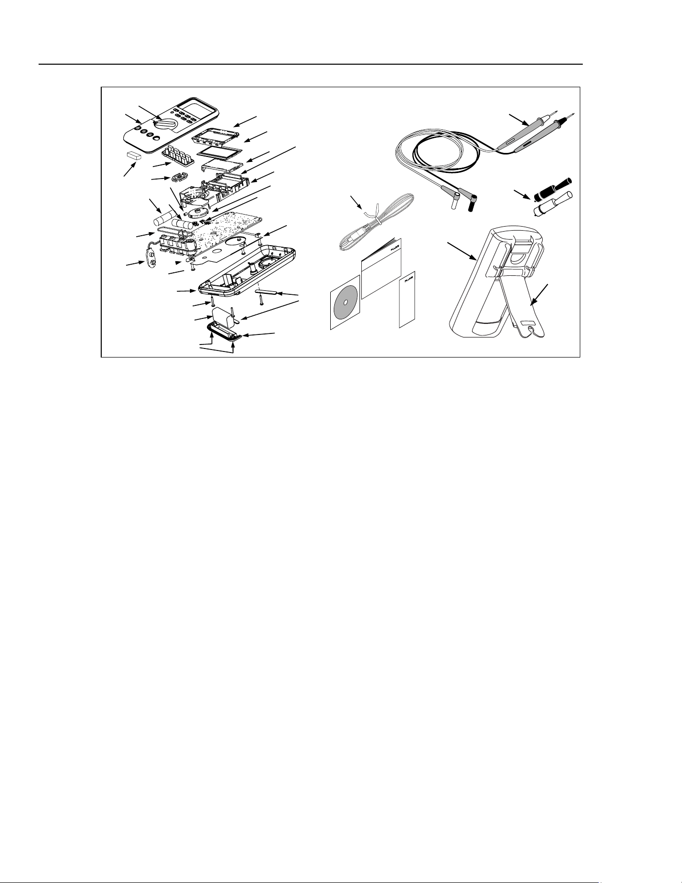
Replacement parts are shown in Table 17 and Figure 8. To order parts and accessories,
refer to “Contacting Fluke”.
Table 17. 80 Series V Final Assembly
Ref Des Description
Part
Number
Qty
AC72 Alligator Clip, Black 1670652 1
AC72 Alligator Clip, Red 1670641 1
BT1 Battery, 9 V 2139179 1
BT2 Cable Assy, 9 V Battery Snap 2064217 1
CR6 Lightpipe 2074057 1
F1W Fuse, 0.440 A, 1000 V, FAST 943121 1
F2W Fuse, 11 A, 1000 V, FAST 803293 1
H2-4 Screw, Case 832246 3
H5-9 Screw, Bottom Shield 448456 5
J1-2 Elastomeric Connector 817460 2
J3 Top Shield Contact 674853 1
MP10,
MP11
Foot, Non-Skid 824466 2
MP2 Shield, Top 2073906 1
MP4 Shield, Bottom 2074025 1
MP5 Case Top (PAD XFER) With Window (83-5) 2074002
MP5 Case Top (PAD XFER) with Window (87-5) 2073992 1
MP5 Case Top (PAD XFER) with Window (88-5) 2115202 1
MP6 Case Bottom 2073871 1
MP8 Knob, Switch (PAD XFER) 2100482 1
MP9 Detent, Knob 822643 1
MP13 Shock Absorber 828541 1
MP14 O-Ring, Input Receptacle 831933 1
MP15 Holster w/ Tilt Stand 2074033 1
MP22 Battery Door 2073938 1
MP27-
MP30
Contact RSOB 1567683 4
MP31 Mask, LCD (PAD XFER) (83-5) 2073961 1
MP31 Mask, LCD (PAD XFER) (87-5) 2073950 1
MP31 Mask, LCD (PAD XFER) (88-5) 2112410 1
MP41 Housing, RSOB 2073945 1
MP390-
391
Access Door Fastener 948609 2
NA Tiltstand 2074040 1
S2 Keypad 2105884 1
TL75 Test Lead Set 855742 1
TM1 80 Series V Getting Started Manual (Multi-language) 2101973 1
TM2 80 Series V Quick Reference Card 2101986 1
TM 2 88 V Quick Reference Card 2279006 1
TM3 CD ROM (Contains 80 Series V Users Manual ) 2101999 1
TM3 CD ROM (Contains 88 V Users Manual ) 2278999 1
TM4
(not
shown)
80 Series V Calibration Manual (this manual) 2102915 1
U5 LCD, 4.5 DIGIT,TN, Transflective, Bar Graph, OSPR80 2065213 1
MP81 80BK Thermocouple Assembly, K-Type, Beaded, Molded Dual Banana Plug,
Coiled
1273113 1
WTo ensure safety, use exact replacement only.
1.888.610.7664 sales@GlobalTestSupply.com
Fluke-Direct.com
80 Series V
Calibration Manual
28
H2-4 (3)
BT1
MP390-391
MP6
MP22
MP10-11
MP5
Holster
MP15
Alligator Clips
TM3
TM2
TL75
Test Lead Set
Tilt Stand
MP8
TM1
W
F2
F1
MP14
S2
MP31
U5
CR6
MP2
MP4
MP81
MP9
MP41
J1-2
MP27-30
J3
H5-9 (5)
MP66
AC72
MP13
BT2
aom015c.eps
Figure 8. 80 Series V Final Assembly
1.888.610.7664 sales@GlobalTestSupply.com
Fluke-Direct.com