

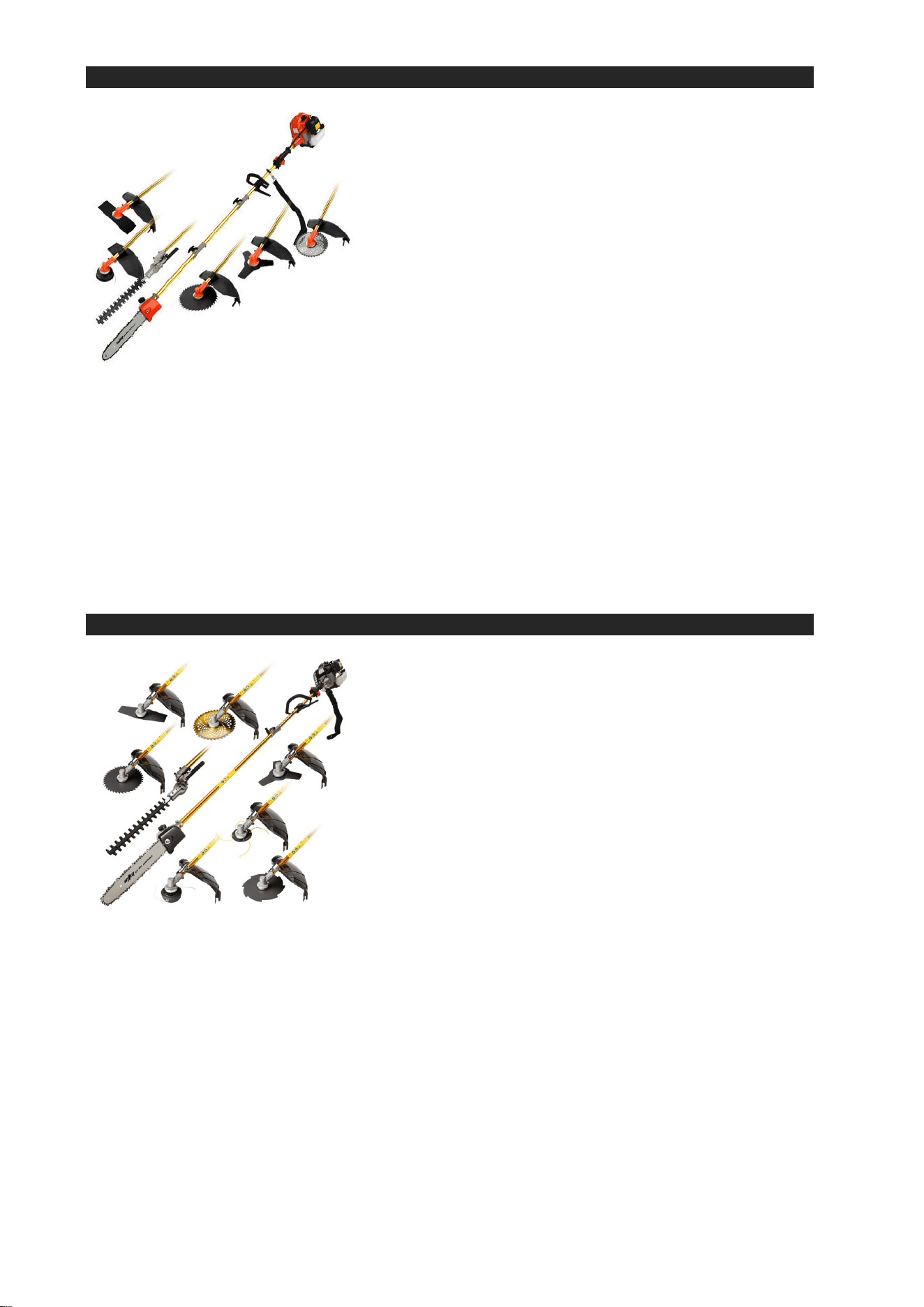
Pole Tool Range
User manual
WARNING!
Read and follow all safety warnings and
instructions carefully before using this
machine. Failure to follow the warnings
and instructions may result in electric
shock, fire and/or serious injury. Save this
manual for future reference.
ATTENTION!
Products covered by this manual will vary
in appearance, assembly, inclusions,
description and packaging.
NOTE!
This manual also covers backpack style
machines with a flexible shaft as well as
options / accessories that may not be
suitable for the machine you have
purchased.

Index
Index ................................................................................................................................................................... 1
Safety Warnings ................................................................................................................................................. 2
Parts Diagram .................................................................................................................................................... 5
Assembly ............................................................................................................................................................ 6
Assembly cont... ................................................................................................................................................. 7
Assembly cont... ................................................................................................................................................. 8
Assembly cont... ................................................................................................................................................. 9
Assembly cont... ............................................................................................................................................... 10
Assembly cont... ............................................................................................................................................... 11
Before Use ....................................................................................................................................................... 12
Starting the engine ........................................................................................................................................... 13
Starting the engine cont… ............................................................................................................................... 14
How to Attach Blades and Accessories ........................................................................................................... 17
Hedge Trimmer ................................................................................................................................................ 18
Pruning Chainsaw ............................................................................................................................................ 19
Maintenance ..................................................................................................................................................... 22
Maintenance cont... .......................................................................................................................................... 23
Transporting/Storage ....................................................................................................................................... 24
Troubleshooting ............................................................................................................................................... 25
Troubleshooting cont... .................................................................................................................................... 26
Specifications ................................................................................................................................................... 27

250816124100
2
2
Safety Warnings
It is important you read and
understand the instruction
manual before first use and
keep the manual in a safe
place for future reference.
Safety precautions must be
observed to reduce the risk of
personal injury when
operating this machine.
DANGER! Keep clear of power
lines, contact can cause death.
Like all power equipment this unit must
be handled carefully.
Do not expose yourself or others to danger.
Do not permit others to use this machine
unless they have read this manual and are
trained in its operation. Do not operate if
the equipment is damaged or in an
excessively worn state. To reduce fire
hazards keep the engine and silencer free
of debris, leaves or excessive lubricant. Do
not use any attachments or accessories
with the equipment other than the ones
recommended by the supplier. Serious
injury to the operator or bystanders can
result as well as cause damage to the
machine. Always use proper handles and /
or shoulder strap when using the
equipment. Do not use the unit if it is
damaged or poorly adjusted. Never
remove the machine’s guards. Serious
injury to the operator or bystanders could
result as well as damage to the machine.
Never leave the machine running and
unattended. Do not use this unit for any job
other than those for which it is intended as
described in this manual. During or after
operation of the engine, never touch hot
parts such as the muffler, the high voltage
wire or the spark plug. Do not operate the
machine in the rain or under wet
conditions. Always ensure all handles and
guards are fitted when using the machine.
Always keep the machine away from naked
flame or sparks. Always stop the engine
before cleaning / clearing a blockage or
checking, maintenance or working on the
machine.
Working at heights
Always use a scissor lift, never work on a
ladder or in a tree, never work on an
insecure support and never operate your
unit with one hand. Always be sure of a
safe and secure operating position
especially when working at heights.
Clothing and Equipment
Dress properly. Do not wear loose clothing
or jewellery which can be caught in moving
parts. Use of sturdy gloves, non-skid
footwear, and safety glasses is
recommended;
Always wear ear protection. Loud
noises for an extended period of
time may damage your hearing.
Total face and head protection
must be worn to reduce injury
from falling branches.
Wear no-slip heavy duty work
gloves to improve your grip on
the brush cutter handle. Gloves
also reduce the transmission of
machine vibration to your hands.
The dust, vapour and smoke
produced during operation may
be dangerous to health. If the
work area is very dusty or
smoky, wear a respirator.
Transporting the Machine
The engine should be turned off when the
machine is moved between areas and
when transporting or storing the machine.
Always turn off the engine. Always fit the
blade covers before carrying your tool.
When transporting in a vehicle: properly
secure your machine to prevent turnover,
fuel spillage and damage.
Fuelling
Petrol is an extremely
flammable fuel. Keep clear of
naked flames.
Do not spill any fuel. Do not smoke near
fuel or the machine. Always shut off the
engine before refuelling. Do not fuel a hot
engine – fuel may spill and cause a fire.
Open the fuel cap carefully to allow any
pressure build-up in the tank to release
slowly and avoid fuel spillage. Fuel your
machine only in well ventilated areas. If you
spill fuel, wipe the machine immediately –
if fuel gets on your clothing, change
immediately. To reduce the risk of serious
or fatal burn injuries, check for fuel
leakage. If fuel leakage is found, do not
start or run the engine until leak is fixed.
During Operation
Make sure you always have good balance
and secure footing. Always be aware of
your surroundings and stay alert for
possible hazards that you may not hear
due to the noise of the machine. Never
allow children to access the machine.
Avoid operating while people, especially
children are nearby. To reduce the risk of
injury, do not allow any other persons
within a radius of 25 meters of your own
position. To reduce the risk of damage to
property, also maintain this distance from
other objects (vehicles, windows).
After Finishing Work
Always clean dust and dirt off the machine
– do not use any grease solvents. Always
keep the machine clean, especially, the
fuel tank, its surroundings, and the air
cleaner. After the engine has stopped, the
muffler will still be hot. Never place the
machine in any places where there are
flammable materials such as dry grass,
combustible gases or combustible liquids
etc. Replace cutting tool covers.
Maintenance and Repairs
Service the machine regularly. Do not
attempt any maintenance or repair work
not described in the instruction manual.
Have all other work performed by a
servicing dealer. We recommend that you
have servicing and repair work carried out
exclusively by an authorised service
person. Before proceeding to adjust or
repair the machine, be sure to stop the
engine and detach the spark plug lead.
Never attempt to make engine adjustments
while the unit is strapped to the operator.
Always make engine adjustments with the
unit resting on a flat, clear surface.

250816124100
3

250816124100
4
4
250816124100
5
5
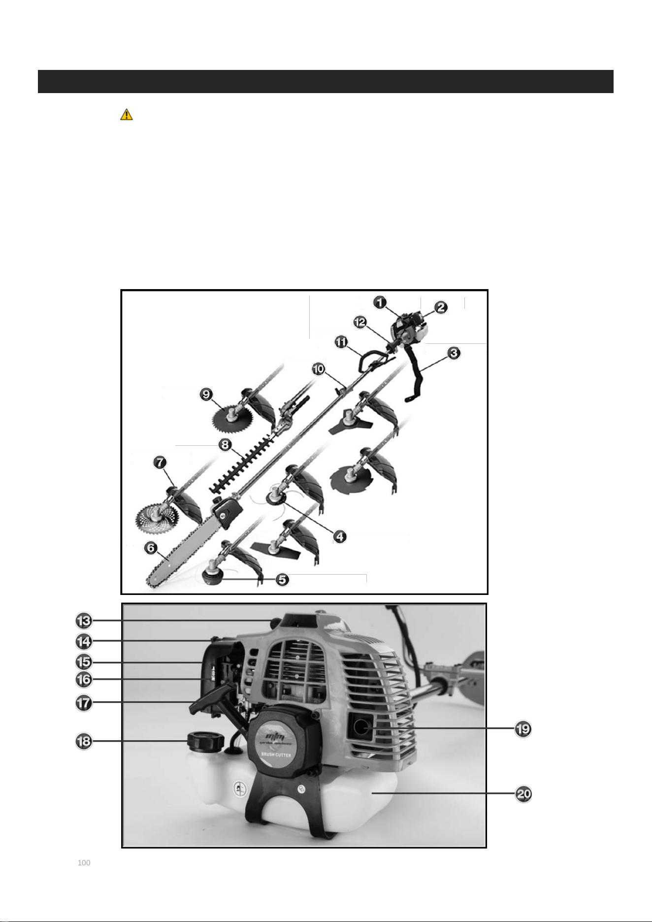
Parts Diagram
ATTENTION! Products covered by this manual will vary in
appearance, assembly, inclusions, description and
packaging.
1. Engine
2. Air Cleaner
3. Shoulder Harness
4. Single line cutter
5. Bump feeder
6. Pruning Chainsaw
7. Deflector Guard
8. Hedge Trimmer
9. Brush Cutter
10. Coupler join
11. Loop Handle
12. Throttle Trigger
13. Spark Plug
14. Air Filter fastener
15. Air filter housing
16. Choke
17. Pull Start cord & handle
18. Fuel filler cap
19. Exhaust outlet
20. Fuel Tank
250816124100
6
6
Assembly
The chainsaw may come with plastic spacers over or around the bar studs - the spacer is for
shipping purposes only and must be removed before mounting the chain bar. After removing
the chain brake cover, remove any spacers, then mount the chain bar as described. Failure to
remove any spacers before assembling and using the chainsaw will present an injury hazard,
damage the unit and will void the warranty.
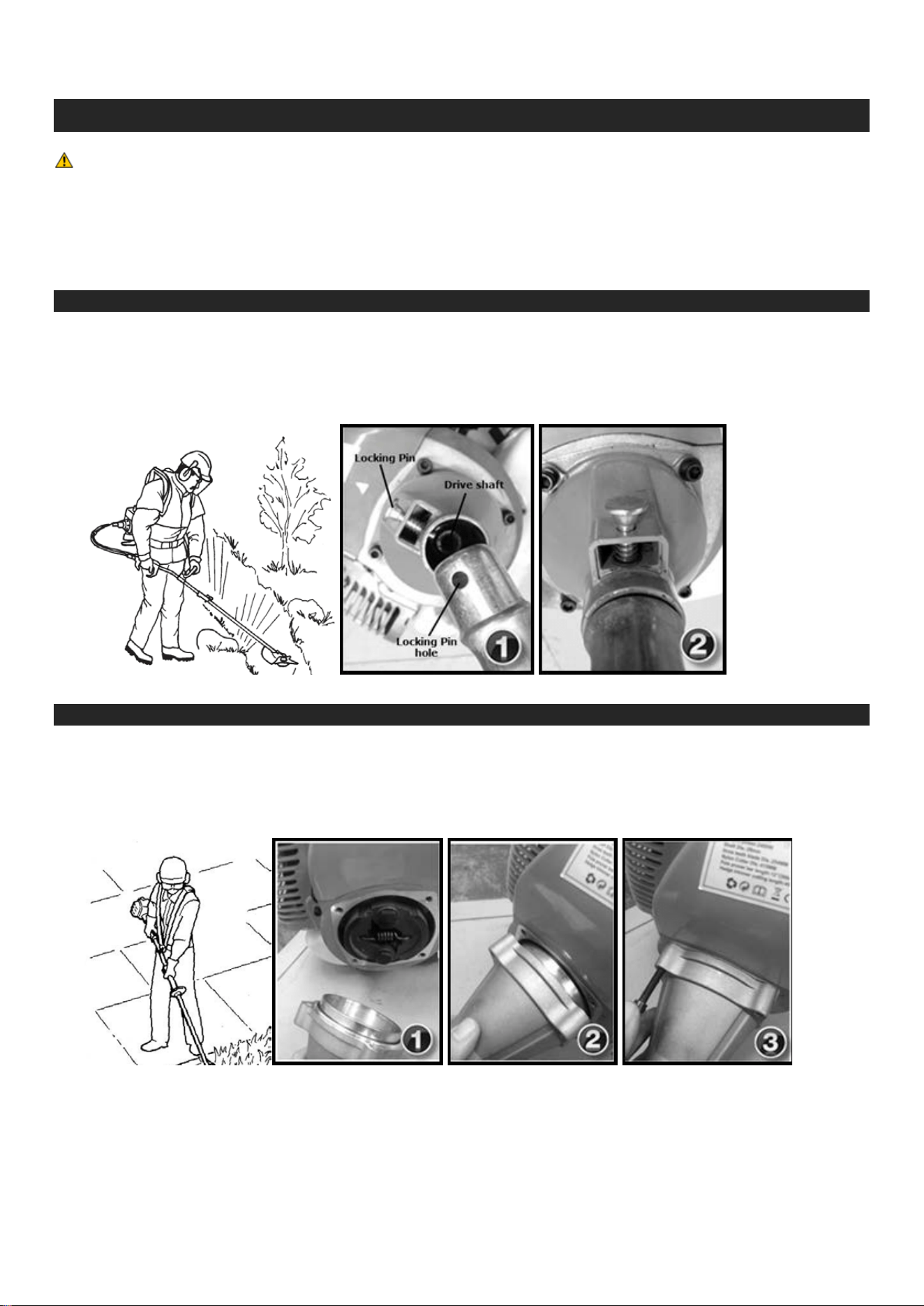
Connecting the engine – backpack type
1. Insert the shaft into the engine case while lifting the locking PIN
2. Push the shaft in all the way, release the locking PIN and slightly move / twist the shaft until the
locking PIN falls into the locking hole.
Connecting the engine – conventional type
1. Remove the bolts from the engine face and set aside.
2. Seat the shaft casing against the engine making sure to line up the axle spline.
3. Using the bolts set aside in step (1), bolt the housing firmly to the engine
(hand tight plus half a turn).
250816124100
7
7
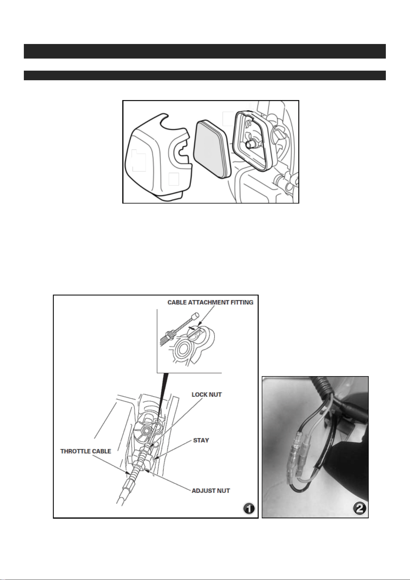
Assembly cont...
Connecting the throttle and switch
1. Remove the air cleaner cover.
2. Wind the “adjust nut” anti-clockwise away from the cable end (figure 1).
3. Wind the “lock nut” anti-clockwise away from the cable end.
4. Slide the “throttle cable” into and through the “stay”.
5. Connect the “throttle cable” end to the “cable attachment fitting”.
6. Wind the “lock nut” clockwise toward the holding plate till it is flush against the “stay”.
7. Using a spanner - tighten the throttle “adjust nut” until it locks against the “lock nut” and “stay”.
8. Connect the throttle switch wires (figure 2). Wire colours may or may not match, it does not matter
which way they are connected.
250816124100
8
8
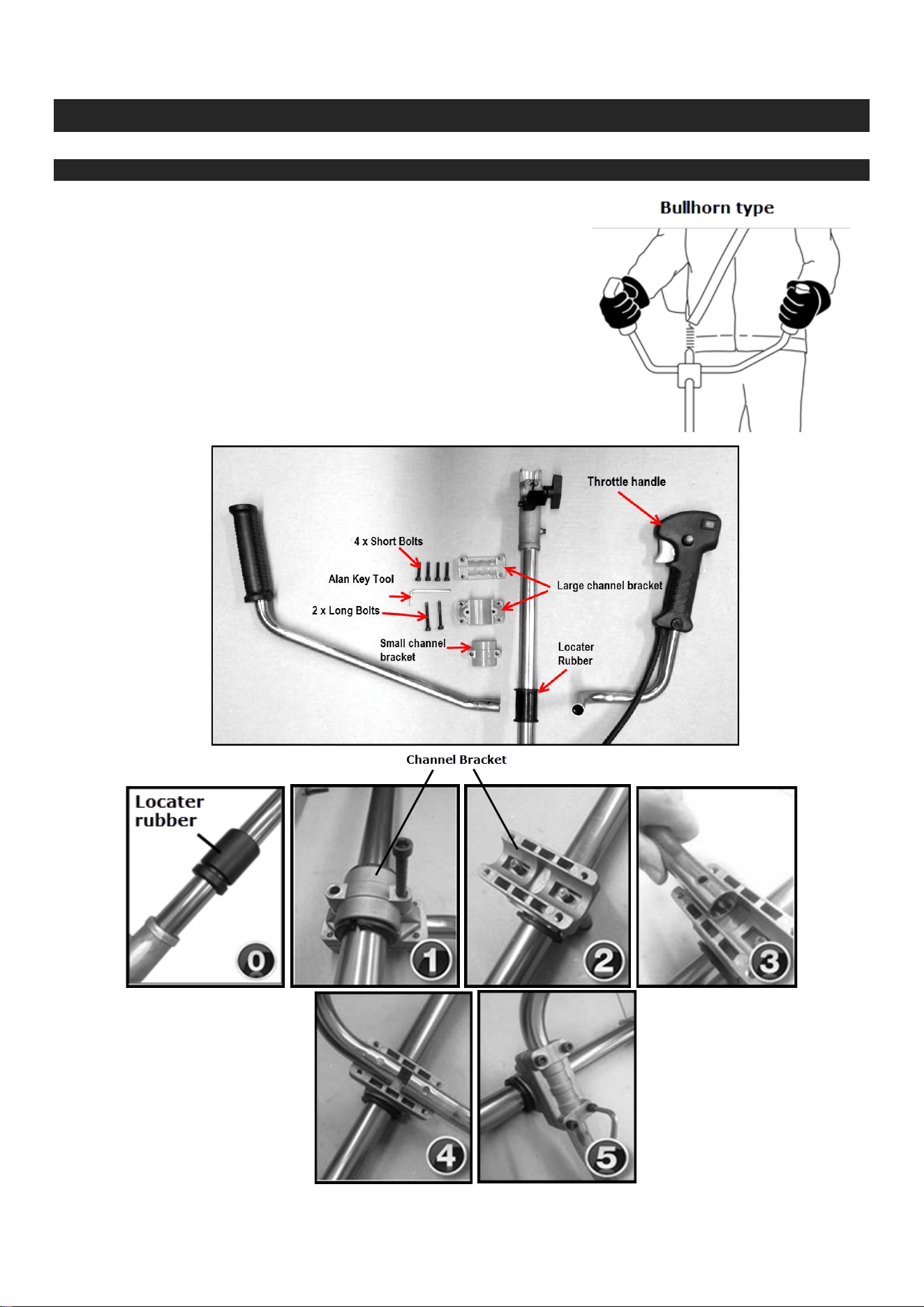
Assembly cont...
Assemble the Bullhorn type handle
1. Set the engine down on a flat surface in the upright position.
2. Locate the handle “locater rubber” (figure 0) in a position allowing
mounting of the handles in a comfortable location.
3. Firmly bolt the “small channel bracket” and “Large channel
bracket” base to the “Locator rubber” using the 2 long bolts and
an Alan Key (figures 1 & 2).
4. Position the two handle bars onto the protruding bolts (see
figures 3 & 4).
5. Bolt the large “channel bracket” clamp over the “channel bracket”
and handles using the “4 short bolts” and an “Alan key tool”
(figure 5).
250816124100
9
9
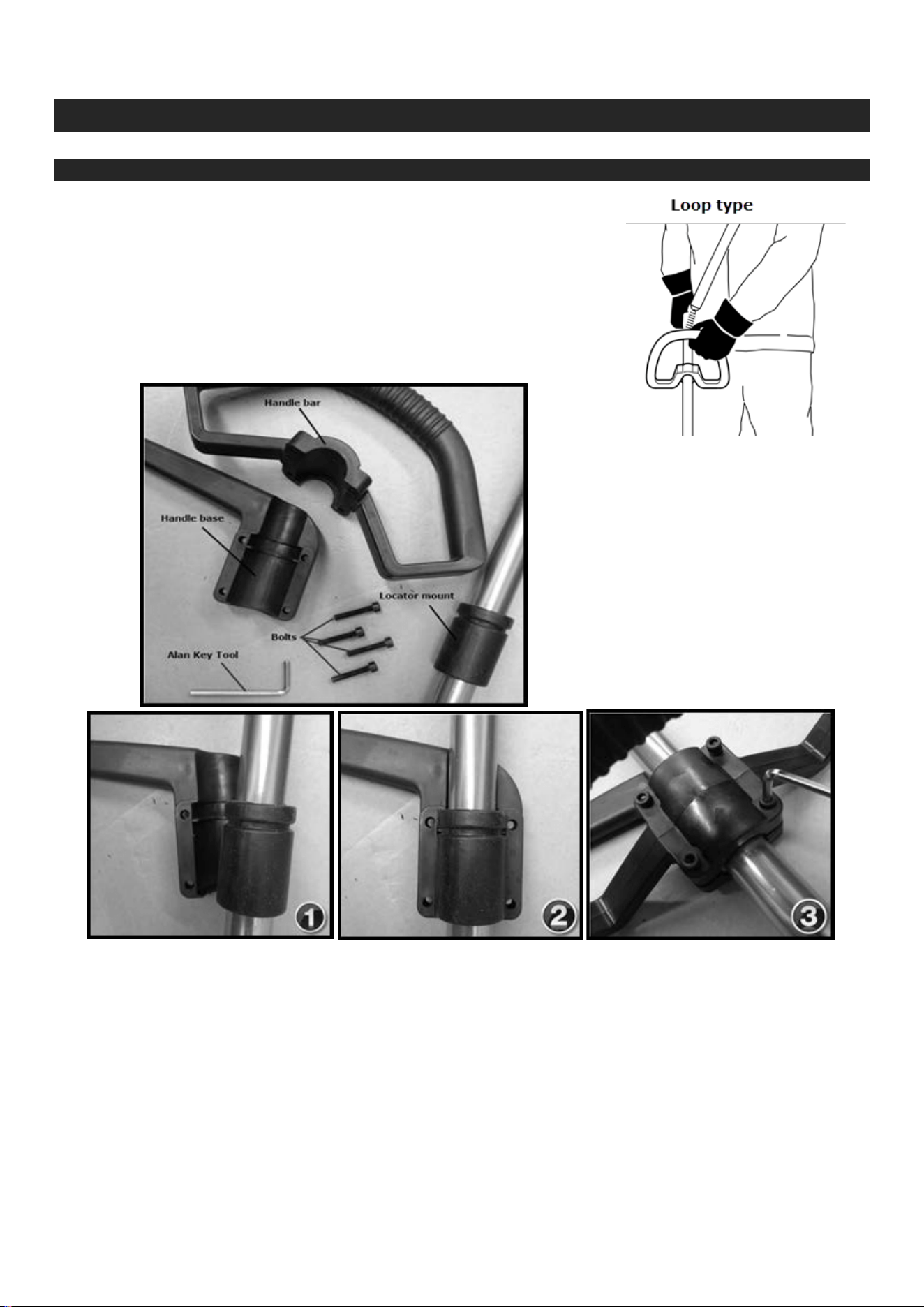
Assembly cont...
Fitting the Loop type handle
1. Set the engine down on a flat surface in the upright position.
2. Position the rubber “locator rubber” just below the throttle in a
position allowing mounting of the handles in a comfortable location.
3. Holding the handle base under the locator mount place the “handle
bar” over the base.
4. Firmly bolt the “handle bar” to the base using the 4 bolts and an
Alan Key. Screw each bolt down an even amount until the “handle
bar” does not flex or slide on the shaft.
250816124100
10
10
Assembly cont...
Fitting the deflector shield
1. Remove the two bolts and fixing plate form the deflector shield using an Alan key and set aside.
2. Place the deflector shield over the gear head (figure 5)
3. Secure the shield in place with the two bolts set aside earlier using the Alan key.
250816124100
11
11
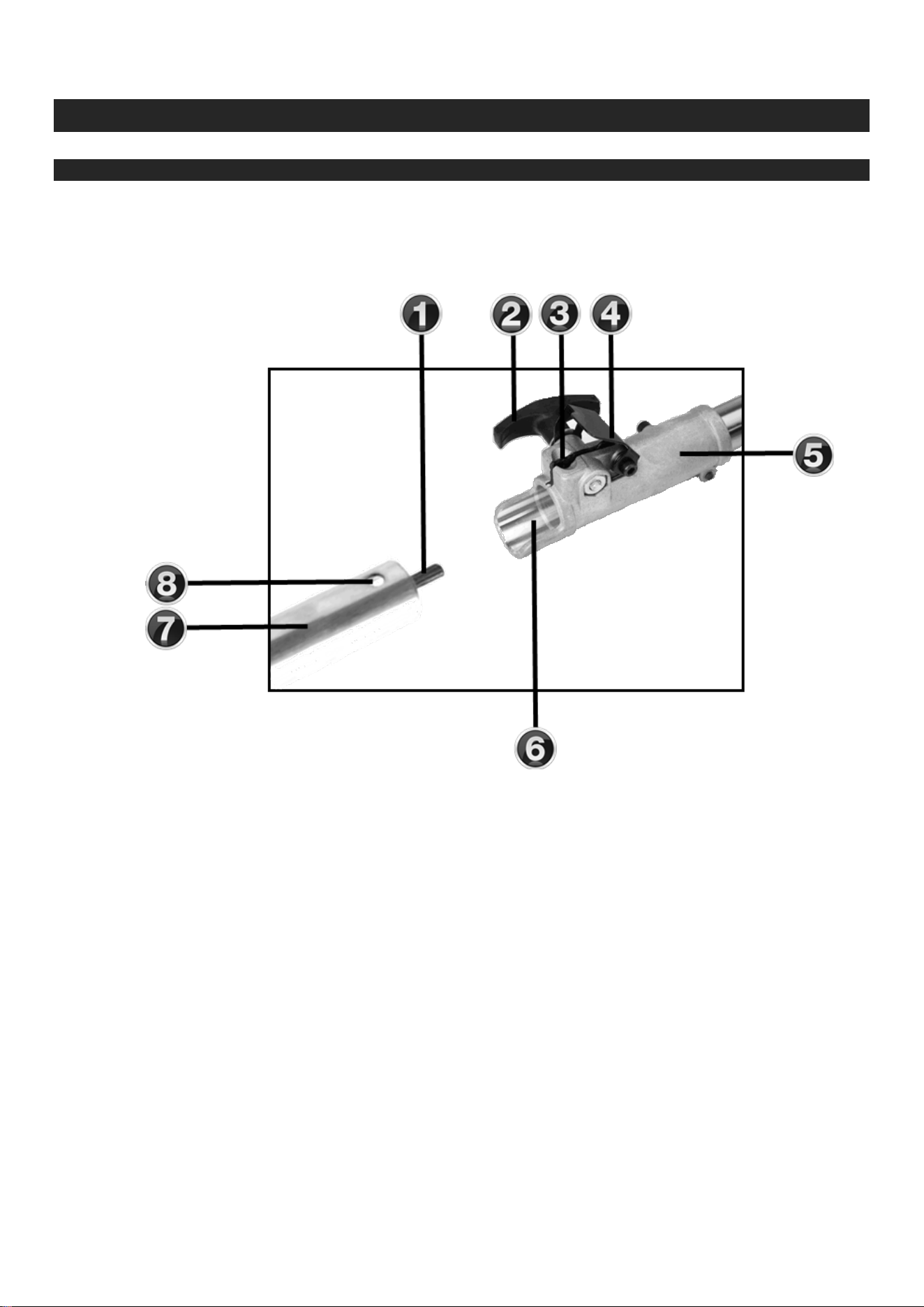
Assembly cont...
Removing and fitting pole extensions
1. Drive shaft / spindle
2. Coupler screw handle
3. Latch mechanism
4. Latch protector cover
5. Coupler section
6. Coupler receiver
7. Cutting head/extension
pole
8. Locating hole
1. Place the machine (5) and pole extension (7) on a clean, flat surface so both assemblies are end to
end.
2. Make sure the latch protector (4) and the locking hole (8) on the tube assembly are facing up.
3. Loosen the coupler screw handle (2) and lift the latch cover up if it doesn’t rise on its own.
4. Press the latch mechanism (3) and insert the Cutting head/extension (7) into the coupler receiver (6)
all the way.
5. Release the latch mechanism (3) and rock the Cutting head/extension (7) back and forth until the
latch (3) snaps into place.
6. When the two tube halves are locked together, push the latch protector (4) down and tighten the
coupler screw handle (2).

250816124100
12
12
Before Use
Adding Fuel
WARNING! Do not use fuel
substitutes such as ethanol
or methanol on your engine,
using such fuel will cause
damage and void any
applicable warranty.
ATTENION! Before refuelling
ensure the engine is
switched off and has cooled
ATTENTION! Two stroke
engines must be used with a
25:1 ratio of fuel to 2-stroke
oil mixture (refer to table
below)
NOTE! It is normal for smoke
to be emitted from a new
engine for the first 5 hours of
use while running in.
Two Stroke Engines
IMPORTANT! Use only
clean, fresh non-ethanol
95+ unleaded.
IMPORTANT! Do not
overfill the fuel tank.
IMPORTANT! Never use
stale or contaminated fuel
to mix with 2-stroke oil.
IMPORTANT! Do not let
dirt and water into the fuel
tank.
IMPORTANT! Tighten the
fuel filler cap securely after
adding fuel.
• Clean surface around fuel cap to prevent contamination.
• Loosen fuel cap slowly. Rest the cap on a clean surface.
• Carefully pour fuel into the tank. Avoid spillage.
• Prior to replacing the fuel cap, clean and inspect the gasket.
• Immediately replace fuel cap and hand tighten. Wipe up any fuel spillage.

250816124100
13
13
Starting the engine
CAUTION! The starter grip
can be drawn back very
quickly before you can release
it. This may pull your hand
forcefully toward the engine
and cause an injury.
CAUTION! Do not allow the
starter grip to snap back.
Return it slowly by hand.
WARNING! When starting the
engine, make sure the cutting
attachment is well clear of
bystanders, pets or objects.
The attachment may rotate
during start-up.
WARNING! The cutting
attachment will engage and
rotate as the engine starts and
accelerates.
CAUTION! The recoil starter
can be damaged by abuse.

250816124100
14
14
Starting the engine cont…
Starting a Flooded Engine
CAUTION! Incorrect spark plug installation can result in serious engine damage.
1. Pull the “spark plug cap” off the “spark plug”.
2. Using a spark plug wrench; remove the “spark plug” (turn
counter clockwise to remove).
3. Push the choke lever down.
4. Hold the throttle trigger all the way in (full throttle)
5. Pull the starter handle rapidly with your right hand to expel/clear
the excess fuel from the combustion chamber.
6. Clean the “spark plug” with a cloth to wipe away any excess
fuel or oil deposits.
7. Reinstall a “spark plug” and tighten it firmly; hand tight plus 1/3
a turn with the spark plug wrench.
8. Repeat the WARM ENGINE starting procedure above.
9. If the engine still fails to start, see the troubleshooting section
near the end of this manual.
Stopping the Engine
Warning! The cutting attachment continues to rotate for a short
period after the throttle is released or the engine is switched off
(flywheel effect).
Stop the engine by setting the “STOP SWITCH” to “OFF” position.

250816124100
15
15
Check and Adjust Idle Speed
1. Start the engine and leave it idle, for two or three minutes,
or until it warms up.
NOTE! The Mixture screw is the one with a spring
wrapped around it.
2. If the cutting attachment rotates rapidly while the engine is
idle, reduce idle speed by turning the idle screw counter
clockwise as necessary.
3. If the engine is stalling and won't idle, increase the idle
speed by turning the idle screw clockwise.

250816124100
16
16
Adjusting the Carburettor
WARNING! The
cutting attachment may
rotate when the engine is
at an idle speed.
Note! The engine will
return to idle speed after
the throttle trigger is
released.
Note! You may require
moderate level of
mechanical knowledge to
service your machine, if in
doubt please contact a
service centre.
Note! As a rule the
engine idle should be
turned down to a minimum
so that the gear head is
not spinning rapidly and
the engine is only “just”
running.
Return idle and mixture screws to factory setting
1. Remove all cutting accessories from the gear head.
2. Turn the Idle screw clockwise until it just begins to tighten (do not tighten it)
3. Turn the Idle screw counter clockwise by 9.5 turns.
4. Turn the Mixture screw clockwise until it just begins to tighten (do not tighten it)
5. Turn the Mixture screw counter clockwise by 3 turns.
6. Now start the engine.
7. Ensure the choke is down and the engine is warm.
8. Pull the throttle trigger in all the way (full throttle)
9. With the engine running at full throttle; turn the mixture screw clockwise until the engine is running at its
absolute fastest.
CRITICAL! Prevent engine damage once the engine is running at its fastest; turn the mixture screw
counter clockwise by ¼ of a turn.
10. For fine tuning of idle speed, attach a cutting head and adjust the idle screw to minimise cutting tool
movement while keeping the engine fast enough to run smoothly.
250816124100
17
17
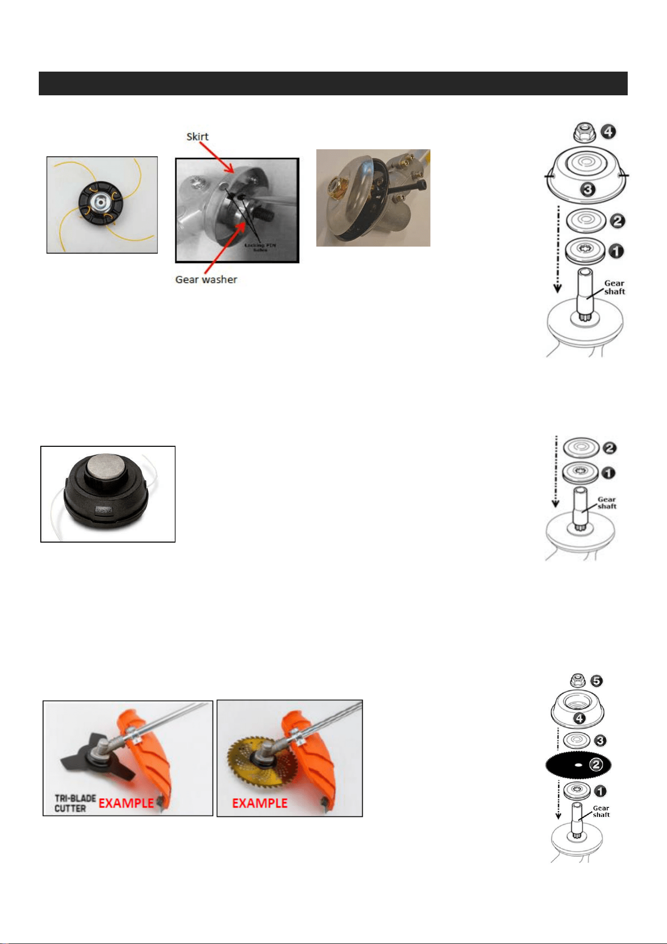
How to Attach Blades and Accessories
Single Line Cutter
Fig. 1
1. Place
the gear washer and washer over the shaft.
2. Align the holes in the skirt and gear washer and place a metal rod (screwdriver or
allen key) into the holes to secure them. (Fig. 1).
3. Place the Single Line Cutter and screw the bolt on anti-clockwise.
NOTE: This shaft and bolt uses a reverse thread to prevent attachments becoming loose and falling
when in use!
4. Screw the bolt on in the opposite direction (anti-clockwise)
5. Remove
metal rod from holes.
Bumper Head:
1. Place the gear washer and washer onto the shaft.
2. Align the holes in the skirt and gear washer and place a metal rod (screw driver or allen key). (Fig. 1)
3. Screw
the bumper head anti-clockwise directly onto the shaft.
NOTE: This shaft and bumper head uses a reverse thread to prevent attachments becoming loose and
falling when in use!
NOTE: Keep all remaining bolts and washers to install other cutting options (see following section on
Metal cutting blades).
Blades:
1. Place the gear washer and then the blade onto the shaft.
2. Place the blade onto the shaft and then the washer.
3. Align the holes in the skirt and gear washer and place a metal rod (screwdriver or allen
4. Bolt
3. Single Line
Cutter
2. Washer
1. Gear Washer
2. Washer
1. Gear Washer
5. Bolt
4. Cover Plate
3. Single Line Cutter
2. Washer
1. Gear Washer

250816124100
18
18
key) into the holes to secure them. (Fig 1)
4. Place the cover plate on the shaft and the screw on the bolt anti-clockwise.
NOTE: This shaft and bolt uses a reverse thread to prevent attachments becoming loose and falling
when in use!
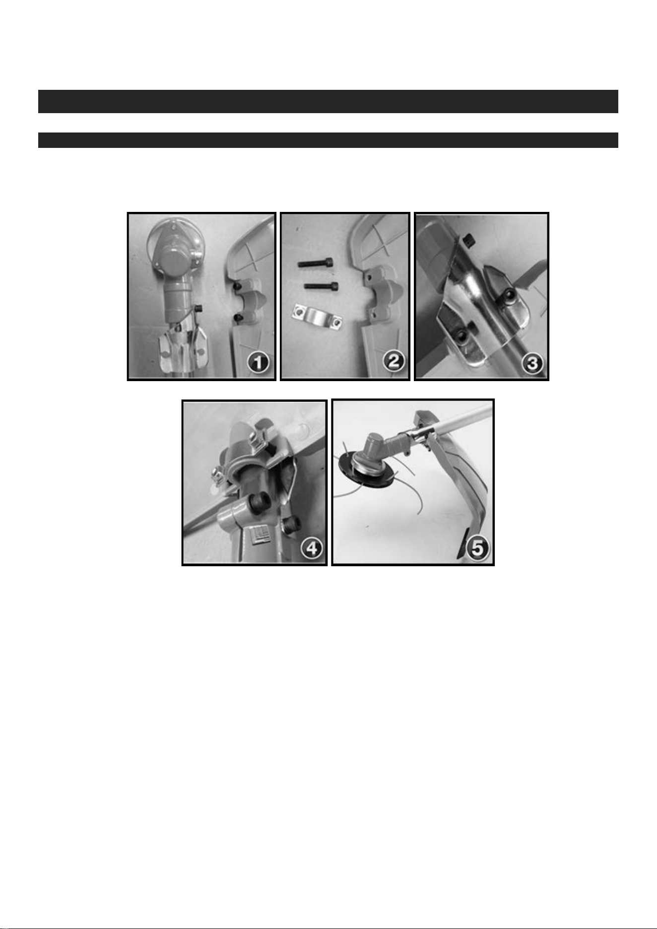
Hedge Trimmer
WARNING! The cutter blades are very sharp. Do not handle the cutter assembly unless the protective
blade cover is in place.
IMPORTANT! Make sure the “cutter bar” is locked in the storage/transport position (folded back) and
the protective cover is installed over the cutter blades when not in use.
1. With your right hand, grasp the handle, located immediately behind the hand guard. With your left
hand, grip the adjustment lever on the cutter assembly (figure 1).
2. With the index finger of your left hand, press the latch release. With your left thumb, press the latch
lock (figure 2-3).
3. The cutting blade may be set in various positions (figure 4).
4. Remove the cover from the cutter blade. The engine now may be started (refer to section “Starting
the Engine”).
250816124100
19
19
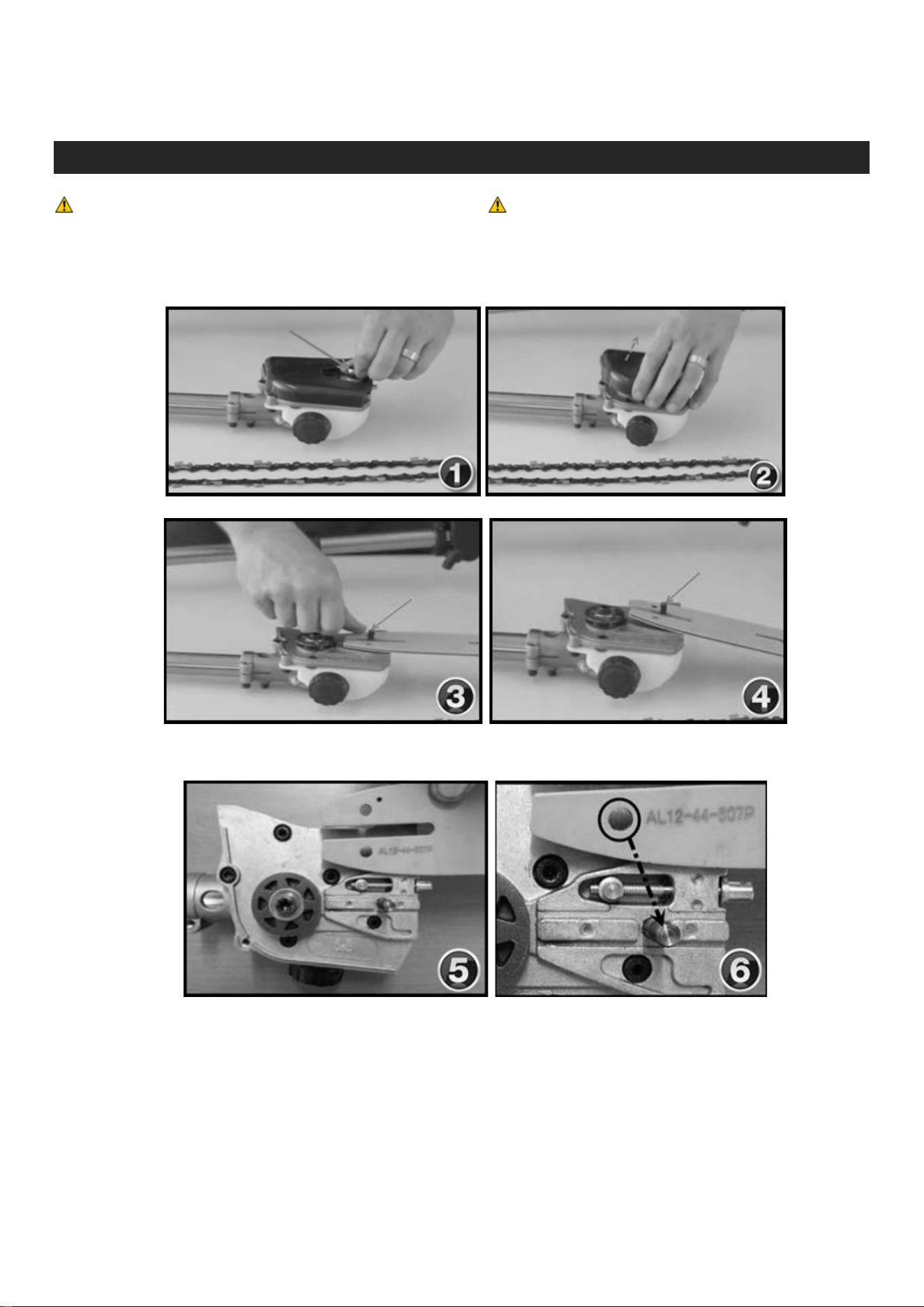
Pruning Chainsaw
WARNING! When not in use ALWAYS use the
protective chain cover.
WARNING! The Chain is extremely sharp.
Never touch the chain without using cut-proof
gloves.
1. Unscrew the 10mm “Main Nut” and remove the black/orange plastic cover.
2. Rest the chain bar on the gear assembly (figures 3-4) and let it sit there until the chain is attached.
3. Be sure to line up the PIN with the adjusting hole on the saw blade (figures 5-7)

250816124100
20
20
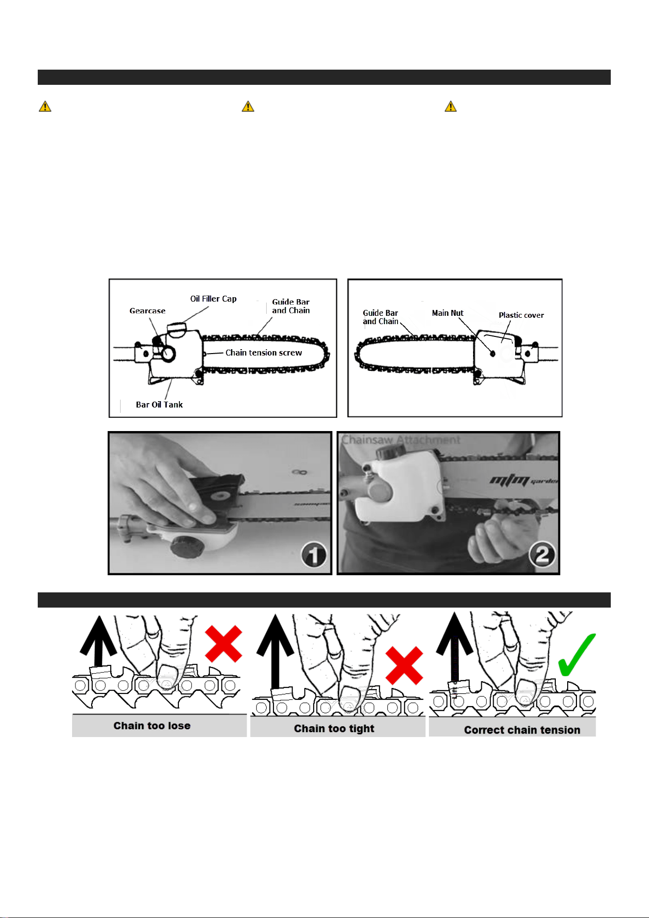
4. Wrap the chain around the drive gear then; while supporting the bar, wrap the chain around the rest
of the chain bar (figure 8)
5. Make sure the chain is seated properly on the chain bar all the way round, it should fit seamlessly.
6. Replace the black/orange plastic cover with the flat washer first followed by the spacer ring and then
the 10mm “Main Nut”. Leave the nut a little loose for now.
250816124100
21
21
Adjusting the chain using the chain tensioner
WARNING! Always use
protective, non-cut gloves
when touching the cutting
chain.
DANGER! Always
disconnect the “spark plug
lead” before touching the
cutting chain.
IMPORTANT! After
running a new chain for
5min the tension must be
re-checked. An old chain
must be checked every
15min of use.
1. Disconnect the “spark plug lead” before adjusting your chain.
2. Slightly loosen the 10mm “main nut” on the black/orange “plastic cover” (1) and tighten the chain
tensioner (2) with a flat bladed screw driver until the chain is tight enough to not jump off the “guide
bar”, the chain must have some give or stress on the machine will result.
How to tension the cutting chain (use non-cut gloves)
4. Using a pair of protective gloves pull the chain around the bar by hand and loosen the
adjustment if you feel tight spots.

250816124100
22
22
Perform a Snap Test
A quick way to measure the tension of a chainsaw chain is to perform what's known as a "snap test." A
properly tensioned chain will rapidly snap back into position around the top of the bar and show no signs of
sagging along the bottom of the bar.
1. Start by disconnecting the chainsaw's spark plug lead.
2. While holding the chainsaw in one hand, grasp the chain along the top centre of the chainsaw's bar
with two fingers of your other hand. (Always wear heavy gloves and protective eyewear when
performing this test.)
3. Lift the chain away from the bar and then quickly release it.
If the chain falls loosely into position along the top of the bar or sags along the bottom of the bar the
tension needs to be adjusted.
Maintenance
WARNING! Always wear gloves when working around the cutter assembly
1. Carefully remove any accumulating dirt or fragments from the muffler and fuel tank. Dirt build-up in
these areas can lead to engine overheating, fire, or premature wear.
2. Check for loose or missing screws or components.
3. Make sure the cutting attachment is free from dirt and securely fastened.
4. Check the entire machine for leaking fuel or grease.
5. Make sure nuts, bolts and screws (except carburettor adjusting screws) are tight.
6. Clean any fragments or dirt from the hedge trimmer cutter blades.
7. Lubricate the blades before use and after refuelling.
8. Check the cutters for damage or incorrect adjustment.
9. Make sure the cutter attachment is securely fastened.
10. Keep the spark plug and wire connections tight and clean.
11. Remove all dirt and debris from the engine, check the cooling fins and air cleaner for clogging, and
clean as necessary.
WARNING!
Before performing any
maintenance, repair, or cleaning
work on the unit, make sure the
engine and cutting attachment are
completely stopped. Disconnect
the spark plug wire before
performing service or maintenance
work.
WARNING!
Non-standard parts may not
operate properly with your unit and
may cause damage and lead to
personal injury.
WARNING!
Operating the engine without a
muffler or with a damaged muffler
installed can increase engine the
noise sufficiently and lead to
hearing loss.
Note!
This machine must never be
operated with a defective or
missing spark arrestor or muffler,
Make sure the muffler is well
secured and in good condition. A
damaged or damped muffler is a
fire hazard and may cause hearing
loss
.

250816124100
23
Maintenance cont...
250816124100
24
24
Transporting/Storage
CAUTION!
Fuel stored in the carburettor
for extended periods can
cause hard starting, and
could also lead to increased
service and maintenance
costs.
IMPORTANT!
Use only clean, fresh non-
ethanol 95+ unleaded.
IMPORTANT!
If the machine will not be
used for 30 days or longer,
use the following procedures
to prepare it for storage.
Clean external parts thoroughly and apply a light coating of oil to all metal surfaces.
1. Remove the spark plug and poor about 3ml of oil into the cylinder through the spark plug hole.
Slowly pull the recoil starter 2 or 3 times so oil evenly coat the interior of the engine. Reinstall
the spark plug.
2. Before storing the machine, repair or replace any worn or damage parts. Make sure the
protective covers are in place.
3. Blow dust / debris out of the air cleaner element using compressed air if available.
4. Store the machine in a clean, dry, dust-free area.
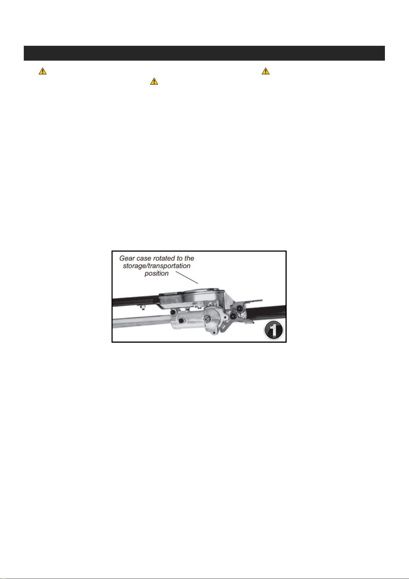
5. Always ensure the attachments / tools have the appropriate covers on any blades and hedge
trimmers are folded into the storage / transportation position (see figure 1 below)

250816124100
25
25
Troubleshooting
Does the engine
crank?
Good compression?
Engine still will not
start.
If ‘yes’
If ‘no’
If ‘yes’
Does the tank
contain fresh fuel
or the proper
grade
?
Is fuel visible and
moving in the
return line when
priming
?
(pole tools only
)
Is there spark at the
plug wire terminal?
Check the spark
plug.
If ‘yes’
If ‘yes’
If ‘yes’
If ‘yes’
A) Faulty recoil starter.
B) Fluid in the crankcase.
C) Internal damage.
A) Loose spark plug.
B)
Excess wear on cylinder
, piston
, rings
.
Fuel incorrect, stale, or contaminated; mixture incorrect.
Check for clogged fuel filter and/ or vent.
(
pole tools only
)
A) The ignition switch is in “OFF” position.
B
) Shorted ignition ground
.
C) Faulty ignition unit
.
A) If the plug is wet
, excess fuel may be in the cylinder.
B
) The plug is fouled or improperly gapped
.
C) The plug is damaged internally or the wrong size.
If ‘no’
If ‘no’
If ‘no’
If ‘no’
If ‘no’
If the engine still does not
start
, take the machine to
an authorised service
center.
Tighten and re-test.
If ‘no’
Refill with fresh fuel
/
oil
mixture
.
If ‘no’
Replace fuel filter or vent as
required and restart
.
(
pole tools only)
If ‘no’
Move switch to “ON” position
and restart.
If ‘no’
1
) Crank engine with the plug
removed, reinstall the plug and
restart.
2
) Clean and re-
gap the plug to
0.6mm-0.7
mm and restart.
If ‘no’
If ‘no’
If ‘yes’
Engine does not start

250816124100
26
26
Troubleshooting cont...
Is the engine
overheating
?
Engine is rough at
all speeds
.
May also
have black smoke
and / or unburned
fuel at the exhaust
.
Does Problem Persist?
If ‘
No’
Engine making a
knocking or pinging
sound.
If ‘
No
’
-
Operator is overworking the unit
.
-
Carburettor mixture is too lean
.
-
Fan
,
fan cover
, cylinder fins dirty or damaged
.
-
Carbon deposits on the piston or in the muffler
.
-
Clogged air cleaner element
.
-
Loose or damaged spark plug
.
-
Air Leakage or clogged fuel line
.
-
Water in the fuel
.
-
Piston seizure
.
- Faulty carburettor and / or diaphragm.
-
Overheating condition
.
-
Improper fuel
.
-
Carbon deposits in the combustion chamber
.
Take the machine
to an authorised service center.
- Clean or replace the air filter.
-
Tighten or replace the spark plug
.
Restart
.
-
Repair or replace fuel filter and /
or fuel line.
- Refill with fresh fuel /
oil mixture.
- Check fuel octane rating
; check for presence of
alcohol in the fuel
.
Refuel as necessary
.
Low Power
Cut at a slower rate
.
Consult with an authorised servicing dealer
.
Clean
, repair or replace as nessesary.

250816124100
27
27
Specifications
BMRG-BC-65CC7IN1
Manufacturer: Baumr-AG
Engine Type: 2-Stroke
Engine Displacement: 65cc
Engine Output: 4.1hp (peak)
Fuel Type: 95+ Non Ethanol 2-Stroke (25:1 Mix)
Shaft Type: 26mm outer / 8mm 9 spline drive.
Brush Cutter attachment
Gearbox Type: XB - Ball Bearing Commercial - Greasable
Arbor Size: 25.4mm (1 Inch) Anti-clockwise drive direction
Blade Options: 40T Gold Series Saw, 40T Saw, 8T Saw, 3T Slasher,
2T Lawn Edger.
BMRG-2IN1-65CC
Manufacturer: Baumr-AG
Engine Type: 2-Stroke
Engine Displacement: 65cc
Engine Output: 4.1hp (peak)
Fuel Type: 95+ Non Ethanol 2-Stroke (25:1 Mix)
Shaft Type: 26mm outer / 8mm 9 spline drive.
Chainsaw attachment
Bar Length / Type: 12" Sprocket Nose
Bar Oil Capacity / Type: 150mL “Chainsaw bar oil” or Similar
Chain Type: Low Kickback Premium Semi-Chisel
Chain Spec: 12", Pitch 3/8", Gauge 0.05, Links 44
Hedge Trimmer attachment
Gearbox Type: XH - Ball Bearing Commercial - Greasable
Blade Length / Type: 450 mm Dual Oscillating
Blades Material: Ultra-Hardened Knife Steel
Cutting Capacity: 450 mm - max 15mm Diameter
Degrees of Rotation: 270 - 12 incremental positions
.
250816124100
28
28
BMRG-MLT7-65CC
Manufacturer: Baumr-AG
Engine Type: 2-Stroke
Engine Displacement: 65cc
Engine Output: 4.1hp (peak)
Fuel Type: 95+ Non Ethanol 2-Stroke (25:1 Mix)
Shaft Type: 26mm outer / 8mm 9 spline drive.
Brush Cutter attachment
Gearbox Type: XB - Ball Bearing Commercial - Greasable
Arbor Size: 25.4mm (1 Inch) Anti-clockwise drive direction
Blade Options: 40T Gold Series Saw, 40T Saw, 8T Saw, 3T Slasher,
2T Lawn Edger.
Chainsaw attachment
Bar Length / Type: 12" Sprocket Nose
Bar Oil Capacity / Type: 150mL “Chainsaw bar oil” or Similar
Chain Type: Low Kickback Premium semi-Chisel
Chain Spec: 12", Pitch 3/8", Gauge 0.05, Links 44
BMRG-MLT9-65CC
Manufacturer: Baumr-AG
Engine Type: 2-Stroke
Engine Displacement: 65cc
Engine Output: 4.1 hp (peak)
Fuel Type: 95+ Non Ethanol 2-Stroke (25:1 Mix)
Shaft Type: 26mm outer / 8mm 9 spline drive.
Brush Cutter attachment
Gearbox Type: XB - Ball Bearing Commercial - Greasable
Arbor Size: 25.4mm (1 Inch) Anti-clockwise drive direction
Blade Options: 40T Gold Series Saw, 40T Saw, 8T Saw, 3T Slasher,
2T Lawn Edger.
Hedge Trimmer attachment
Gearbox Type: XH - Ball Bearing Commercial - Greasable
Blade Length / Type: 450 mm Dual Oscillating
Blades Material: Ultra-Hardened Knife Steel
Cutting Capacity: 450 mm - max 15mm Diameter
Degrees of Rotation: 270 - 12 incremental positions
.
Chainsaw attachment
Bar Length / Type: 12" Sprocket Nose
Bar Oil Capacity / Type: 150mL “Chainsaw bar oil” or Similar
Chain Type: Low Kickback Premium semi-Chisel
Chain Spec: 12", Pitch 3/8", Gauge 0.05, Links 44

250816124100
29
29
BMRG-PCS-65CC
Manufacturer: Baumr-AG
Engine Type: 2-Stroke
Engine Displacement: 65cc
Engine Output: 3.8hp (peak)
Fuel Type: 95+ Non Ethanol 2-Stroke (25:1 Mix)
Shaft Type: 26mm outer / 8mm 9 spline drive.
Chainsaw attachment
Bar Length / Type: 12" Sprocket Nose
Bar Oil Capacity / Type: 150mL “Chainsaw bar oil” or Similar
Chain Type: Low Kickback Premium Semi-Chisel
Chain Spec: 12", Pitch 3/8", Gauge 0.05, Links 44
MTM-BPACK-BCUTTER62CC
Manufacturer: Baumr-AG
Engine Type: 2-Stroke
Engine Displacement: 65cc
Engine Output: 4.1hp (peak)
Fuel Type: 95+ Non Ethanol 2-Stroke (25:1 Mix)
Shaft Type: Flexible 20mm outer / 6mm.
Brush Cutter attachment
Gearbox Type: XB - Ball Bearing Commercial - Greasable
Arbor Size: 25.4mm (1 Inch) Anti-clockwise drive direction
Blade Options: 40T Gold Series Saw, 40T Saw, 8T Saw, 3T Slasher,
2T Lawn Edger.
MTM-BRUSHCUT-62CC7IN1
Manufacturer: MTM
Engine Type: 2-Stroke
Engine Displacement: 62cc
Engine Output: 3.8hp (peak)
Fuel Type: 95+ Non Ethanol 2-Stroke (25:1 Mix)
Shaft Type: 26mm outer / 8mm 9 spline drive.
Brush Cutter attachment
Gearbox Type: XB - Ball Bearing Commercial - Greasable
Arbor Size: 25.4mm (1 Inch) Anti-clockwise drive direction
Blade Options: 40T Gold Series Saw, 40T Saw, 8T Saw, 3T Slasher,
2T Lawn Edger.

250816124100
30
30
MTMG-2IN1-62CC
Manufacturer: MTM
Engine Type: 2-Stroke
Engine Displacement: 62cc
Engine Output: 3.8hp (peak)
Fuel Type: 95+ Non Ethanol 2-Stroke (25:1 Mix)
Shaft Type: 26mm outer / 8mm 9 spline drive.
Hedge Trimmer attachment
Gearbox Type: XH - Ball Bearing Commercial - Greasable
Blade Length / Type: 450 mm Dual Oscillating
Blades Material: Ultra-Hardened Knife Steel
Cutting Capacity: 450 mm - max 15mm Diameter
Degrees of Rotation: 270 - 12 incremental positions
.
Chainsaw attachment
Bar Length / Type: 12" Sprocket Nose
Bar Oil Capacity / Type: 150mL “Chainsaw bar oil” or Similar
Chain Type: Low Kickback Premium Semi-Chisel
Chain Spec: 12", Pitch 3/8", Gauge 0.05, Links 44
MTMG-7IN1-62CC
Manufacturer: MTM
Engine Type: 2-Stroke
Engine Displacement: 62cc
Engine Output: 3.8hp (peak)
Fuel Type: 95+ Non Ethanol 2-Stroke (25:1 Mix)
Shaft Type: 26mm outer / 8mm 9 spline drive.
Brush Cutter attachment
Gearbox Type: XB - Ball Bearing Commercial - Greasable
Arbor Size: 25.4mm (1 Inch) Anti-clockwise drive direction
Blade Options: 40T Gold Series Saw, 40T Saw, 8T Saw, 3T Slasher,
2T Lawn Edger.
Hedge Trimmer attachment
Gearbox Type: XH - Ball Bearing Commercial - Greasable
Blade Length / Type: 450 mm Dual Oscillating
Blades Material: Ultra-Hardened Knife Steel
Cutting Capacity: 450 mm - max 15mm Diameter
Degrees of Rotation: 270 - 12 incremental positions
.
Chainsaw attachment
Bar Length / Type: 12" Sprocket Nose
Bar Oil Capacity / Type: 150mL “Chainsaw bar oil” or Similar
Chain Type: Low Kickback Premium Semi-Chisel
Chain Spec: 12", Pitch 3/8", Gauge 0.05, Links 44
250816124100
31
31
MTMG-MLT7-62CC
Manufacturer: MTM
Engine Type: 2-Stroke
Engine Displacement: 62cc
Engine Output: 3.8hp (peak)
Fuel Type: 95+ Non Ethanol 2-Stroke (25:1 Mix)
Shaft Type: 26mm outer / 8mm 9 spline drive.
Brush Cutter attachment
Gearbox Type: XB - Ball Bearing Commercial - Greasable
Arbor Size: 25.4mm (1 Inch) Anti-clockwise drive direction
Blade Options: 40T Gold Series Saw, 40T Saw, 8T Saw, 3T Slasher,
2T Lawn Edger.
Hedge Trimmer attachment
Gearbox Type: XH - Ball Bearing Commercial - Greasable
Blade Length / Type: 450 mm Dual Oscillating
Blades Material: Ultra-Hardened Knife Steel
Cutting Capacity: 450 mm - max 15mm Diameter
Degrees of Rotation: 270 - 12 incremental positions
.
Chainsaw attachment
Bar Length / Type: 12" Sprocket Nose
Bar Oil Capacity / Type: 150mL “Chainsaw bar oil” or Similar
Chain Type: Low Kickback Premium Semi-Chisel
Chain Spec: 12", Pitch 3/8", Gauge 0.05, Links 44
MTMG-MLT9-62CC
Manufacturer: MTM
Engine Type: 2-Stroke
Engine Displacement: 62cc
Engine Output: 3.8hp (peak)
Fuel Type: 95+ Non Ethanol 2-Stroke (25:1 Mix)
Shaft Type: 26mm outer / 8mm 9 spline drive.
Brush Cutter attachment
Gearbox Type: XB - Ball Bearing Commercial - Greasable
Arbor Size: 25.4mm (1 Inch) Anti-clockwise drive direction
Blade Options: 40T Gold Series Saw, 40T Saw, 8T Saw, 3T Slasher,
2T Lawn Edger.
Hedge Trimmer attachment
Gearbox Type: XH - Ball Bearing Commercial - Greasable
Blade Length / Type: 450 mm Dual Oscillating
Blades Material: Ultra-Hardened Knife Steel
Cutting Capacity: 450 mm - max 15mm Diameter
Degrees of Rotation: 270 - 12 incremental positions
.
Chainsaw attachment
Bar Length / Type: 12" Sprocket Nose
Bar Oil Capacity / Type: 150mL “Chainsaw bar oil” or Similar
Chain Type: Low Kickback Premium Semi-Chisel
Chain Spec: 12", Pitch 3/8", Gauge 0.05, Links 44

250816124100
32
32
MTM-PCS5IN1
Manufacturer: MTM
Engine Type: 2-Stroke
Engine Displacement: 62cc
Engine Output: 3.8hp (peak)
Fuel Type: 95+ Non Ethanol 2-Stroke (25:1 Mix)
Shaft Type: 26mm outer / 8mm 9 spline drive.
Brush Cutter attachment
Gearbox Type: XB - Ball Bearing Commercial - Greasable
Arbor Size: 25.4mm (1 Inch) Anti-clockwise drive direction
Blade Options: 40T Gold Series Saw, 40T Saw, 8T Saw, 3T Slasher,
2T Lawn Edger.
Hedge Trimmer attachment
Gearbox Type: XH - Ball Bearing Commercial - Greasable
Blade Length / Type: 450 mm Dual Oscillating
Blades Material: Ultra-Hardened Knife Steel
Cutting Capacity: 450 mm - max 15mm Diameter
Degrees of Rotation: 270 - 12 incremental positions
.
Chainsaw attachment
Bar Length / Type: 12" Sprocket Nose
Bar Oil Capacity / Type: 150mL “Chainsaw bar oil” or Similar
Chain Type: Low Kickback Premium Semi-Chisel
Chain Spec: 12", Pitch 3/8", Gauge 0.05, Links 44
MTM-PCS-62CC
Manufacturer: MTM
Engine Type: 2-Stroke
Engine Displacement: 62cc
Engine Output: 3.8hp (peak)
Fuel Type: 95+ Non Ethanol 2-Stroke (25:1 Mix)
Shaft Type: 26mm outer / 8mm 9 spline drive.
Chainsaw attachment
Bar Length / Type: 12" Sprocket Nose
Bar Oil Capacity / Type: 150mL “Chainsaw bar oil” or Similar
Chain Type: Low Kickback Premium Semi-Chisel
Chain Spec: 12", Pitch 3/8", Gauge 0.05, Links 44

250816124100
33
33
MTM-PCS8IN1
Manufacturer: MTM
Engine Type: 2-Stroke
Engine Displacement: 33cc
Engine Output: 1.5 hp (peak)
Fuel Type: 95+ Non Ethanol 2-Stroke (25:1 Mix)
Shaft Type: 26mm outer / 8mm 9 spline drive.
Brush Cutter attachment
Gearbox Type: XB - Ball Bearing Commercial - Greasable
Arbor Size: 25.4mm (1 Inch) Anti-clockwise drive direction
Blade Options: 40T Gold Series Saw, 40T Saw, 8T Saw, 3T Slasher,
2T Lawn Edger.
Hedge Trimmer attachment
Gearbox Type: XH - Ball Bearing Commercial - Greasable
Blade Length / Type: 450 mm Dual Oscillating
Blades Material: Ultra-Hardened Knife Steel
Cutting Capacity: 450 mm - max 15mm Diameter
Degrees of Rotation: 270 - 12 incremental positions
.
Chainsaw attachment
Bar Length / Type: 12" Sprocket Nose
Bar Oil Capacity / Type: 150mL “Chainsaw bar oil” or Similar
Chain Type: Low Kickback Premium Semi-Chisel
Chain Spec: 12", Pitch 3/8", Gauge 0.05, Links 44
PLTPCS62GMTMACAJ
Manufacturer: MTM
Engine Type: 2-Stroke
Engine Displacement: 62cc
Engine Output: 3.8hp (peak)
Fuel Type: 95+ Non Ethanol 2-Stroke (25:1 Mix)
Shaft Type: 26mm outer / 8mm 9 spline drive.
Chainsaw attachment
Bar Length / Type: 12" Sprocket Nose
Bar Oil Capacity / Type: 150mL “Chainsaw bar oil” or Similar
Chain Type: Low Kickback Premium Semi-Chisel
Chain Spec: 12", Pitch 3/8", Gauge 0.05, Links 44

250816124100
34
34
Appendix
© Copyright 2012 - Mills International Trading Pty Ltd.

Some experts believe the incorrect or prolonged use of almost any
product could cause
serious inju
ry or de
a
th. F
or inf
orm
ation th
at
may reduce your risk of serious injury or death consult thepoints
below and additionally, the information available at
www.datastreamserver.com/safety
- Consult all documentation, packaging and
product labelling be fore use. Note that some
products feature online documentation which
should be printed and kept with the p roduct.
- Check product for loose / broken / damaged /
missing parts, wear or leaks (if applicable) be fore
each use. Never use a product with loose / broken
/ damaged / missing parts, wear or leaks (if
applicable).
- Products must be inspected and serviced (if
applicable) by a qualified specialist every 6
months assuming average residential use by a
person of average weight and strength, ab ove
average technical aptitude, on a property
matching average metropolitan specification.
Intended use outside these guidelines could
indicate the product is not suitable for intended
use or may require more regular inspection or
servicing.
- Ensure all possible users of the p roduct have
completed an industry recognised training course
before being given access to the product.
- The product has been supplied by a general merchandise
retailer that may not be familiar with your specific applic ation or
your description of the application. Be sure to attain third party
approval for your application from a qualified specialist before use
regardless of prior assurances by the retailer or its representatives.
- This product is not intended for use where fail-safe operation is
required. As with any product (take an automobile, aircraft,
computer or ball point pen for example) there is always a small
chance of a technical issue that needs to be repaired or may
require replacement of the product or a part. If the possibility of
such failure and the associated time it takes to rectify could in any
situation inconvenience the user, business or employee or could
financially affect the user, business or employee then the product
is not suitable for your requirements. This p roduct is not for use
where incorrect operation or a failure of any kind, including but
not limited to a condition requiring product return, replacement,
service by a technician or replacement of parts could cause a
financial loss, loss of employee time or an in c
onvenience
requiring compensation.
- If this item has been purchased in error considering the points
above simply contact the retailer directly for details of their
returns policies if required.