ICC-500T
Programmable CO₂ Controller
Manual
PPM
%RH
PPM
%RH


Contents
Product Features-----------------------04
Safety Precautions ----------------------04
Technical Parameters ------------------05
S01 CO₂ Module ------------------------05
B01 CO₂ Module ------------------------06
Fault Codes and Trouble shooting Guide -06
Product Introduction --------------------07
Operation Instruction--------------------11

Safety Precautions
To ensure correct and safe use of this product,
please read the entire user manual before using this
product. Failure to abide by the recommendations in
this manual may result in functional impairment of
the product. Warnings in this manual provide
important safety information which should always be
observed:
● Do not subject the device to impacts or shocks,
as this may reduce the accuracy of the sensor.
● Do not place the device or power plug near heat
sources. Heating can result in deformity of the
product and creates a potential fire hazard.
● Do not open the CO₂ controller or touch any
exposed electronic circuits. This may result in
electrical shock.
● Power cord and adapter should be inserted into a
grounded outlet. Failure to use a grounded power
source may result in damage to the product and/or
serious injury even death to the user.
Product Features
● Plug and play, simple operation.
● Dual relays, are able to connect with the CO₂
regulator or generator and the exhaust fan
simultaneously.
● Dual readouts, displays the current measured CO₂
concentration and the set CO₂ concentration
simultaneously.
● CO₂ calibration.
● Programmable high/low CO₂ concentration alarm.
4

Technical Parameters
Brand: INKBIRD
● Model: ICC-500T
● Input Power: 100~240Vac 50/60Hz 10A MAX
● Output Power: 100~240Vac 50/60Hz 10A MAX
(two sockets)
● Disconnection Method: Type 1B
● Pollution Degree: 2
● Rated Impulse Voltage: 1500V
● Automatic Operation: 6000 cycles
● Ambient temperature:
Working Environment: room temperature
Storage Temperature: 0℃~60℃/32℉~140℉
Storage Humidity: 20~80%RH (No freezing or
condensation)
● Warranty Period: 2 years
S01 CO₂ Module
Widely applied in ventilation system, building
control and HVAC equipment
● Measurement Range: 0~9,999 ppm
● Sensing Method: NDIR
● Error: ± (30 ppm+3% MV)
● Response Time (63%): 20 seconds
● Working Temperature: 0℃~50℃/32℉~122℉
Working Humidity: 0~95%RH (non-condensing)
● Calibration Method: CO₂ reading calibration
(current CO₂ concentration Value + CO₂ calibration
value)
5

B01 CO₂ Module
Widely applied in agricultural and livestock
industries, greenhouses, industrial fields and
general ventilation HVAC
● Measurement Range: 0~9,999 ppm
● Sensing Method: NDIR
● Error: ± (30 ppm+5% MV)
● Response Time (90%): 120 seconds
● Working Temperature: 0℃~50℃/32℉~122℉
● Working Humidity: 0~95%RH (non-condensing)
● Calibration Method: CO₂ reading calibration
(current CO₂ concentration value + CO₂ calibration
value)
1 CO₂ Module Power on Instruction
When the CO₂ module is not inserted, the PV and SV
windows display “----”; when the CO₂ module is
inserted, the controller will take about 8 seconds to
identify. When the CO₂ module is identified to be
inserted, the PV window will display 8888 and blink,
the SV window will display the CO₂ concentration
setting. After 120 seconds, CO₂ module works
stably, and the PV window stops blinking and
displays the measured CO₂ concentration. Within
120 seconds, the buttons cannot be operated , the
indicators of WORK1 and WORK2 are off, and the
WORK1 and WORK2 have no output.
2 Button Instruction
2.1 Restore Factory Settings
Hold the button to power on, and the buzzer will
make a short beep, prompting users to restore all
parameters to factory default settings.
2.2 When TR=1 (Continuous Timer Mode) or 2
(Target Timer Mode), the operation starts from the
first stage of the CO₂ Concentration Setting by
default
When TR=1 or 2, hold the button to power on,
the buzzer will make a short beep. This alerts the
user that the controller will start from the first stage
of the CO₂ concentration setting for controlling.
2.3 Button Instruction in the Normal Working
Mode
2.3.1 TR=0 (Normal Mode)
Short press the button, then the PV window will
display HD, the SV window will display the WORK1
CO₂ Difference; short press the button again, the
PV window will display CD, the SV window will
display the WORK2 CO₂ Difference.
If there is no operation for 3 seconds, the device
will automatically exit the HD and CD mode and
return to the normal display mode, or you can press
the or button to quit the mode directly.
2.3.2 TR=1 (Continuous Timer Mode) or 2 (Target
Timer Mode)
Short press the button firstly, the PV window
will display HD, the SV window will display the
WORK1 CO₂ Difference. Short press the button
secondly, the PV window will display CD, the SV
window will display the WORK2 CO₂ Difference.
Short press the button thirdly, the PV window
will display SX (X=01~12), the SV window will
display the current stage CO₂ concentration
setting. Short press the button fourthly, the PV
window will display the unit of current time HX
(X=01~12), the SV window will display the current
remaining working time. Press the button
fifthly, the PV window will display whether the
current segment is in alarm status UX (X=01~12),
and the SV window will display the current alarm
state.
The device will automatically exit the HD and CD
mode and return to the normal display mode if
there’s no operation for 3 seconds, or you can press
the or button to quit the mode directly.
2.3.3 TR=1 (Continuous Timer Mode) or 2 (Target
Timer Mode)
Press and hold the button for 2 seconds to run
the Starting Segment Setting (SST) forcibly, and the
buzzer will make a short beep at the same time.
2.4 Instruction in the Normal Working Mode
Press the button to enter quick setting mode to
set the CO₂ concentration setting. When TR equals
0, the SV will display the CO₂ concentration setting
and blinks. Short press the or button to
increase or decrease the set value. Long press
the or button to increase or decrease the
set value quickly. Press the button again to
confirm the set value and exit the mode. When TR
equals 1 or 2, press the button to enter the
quick setting mode to set the current segment of
the CO₂ concentration setting, the SV screen will
display the current segment of the CO₂
concentration setting and it will blink, then press
the or button to increase or decrease the
set value. Long press the or button to
increase or decrease the set value quickly. Press
the button secondly to switch to current stage
control duration value, press the or button
to modify the time setting value. Press the
button thirdly to switch to whether to alarm after
the completion of the current segment, press
the or button to modify the setting value.
Press the button fourthly to confirm and exit
the mode. If there is no operation, it will exit the
mode after 30 seconds and save the set value
automatically.
2.5 Buttons Instruction in the Setting Mode
Press and hold the button for 2 seconds to
enter the setting mode. The PV window will display
the code of the first menu item CS, if TR equals 1
or 2, the PV window will display the code of the
second menu item HD, and the SV will display the
corresponding set value. Press the button to
scroll down through the menu items to save the
parameters of the previous menu item. Press
the or button to change the setting value.
If there is no operation for 180 seconds in the
setting mode, the device will exit the mode and
save the setting value automatically and then
Fault Codes and Trouble shooting Guide
No
1
2
3
Display
Content
---
Er1
Er2
Error Description
No CO₂ sensor inserted
Clock system error
Flash saves date error
Trouble shooting Guide
Insert the CO₂ sensor into
the product interface.
Unplug the AC adapter and
reconnect it. If the controller
still displays “Er1”, please
contact us.
Unplug the AC adapter and
reconnect it. If the controller
still displays “Er2”, please
contact us.
return to the normal working mode. You can also
hold the button for 2 seconds to quit the mode
and save the setting value directly.
3 Menu Instruction
3.1 Menu Setting Flowchart
6
Product Introduction
1 CO₂ Module Power on Instruction
When the CO₂ module is not inserted, the PV and SV
windows display “----”; when the CO₂ module is
inserted, the controller will take about 8 seconds to
identify. When the CO₂ module is identified to be
inserted, the PV window will display 8888 and blink,
the SV window will display the CO₂ concentration
setting. After 120 seconds, CO₂ module works
stably, and the PV window stops blinking and
displays the measured CO₂ concentration. Within
120 seconds, the buttons cannot be operated , the
indicators of WORK1 and WORK2 are off, and the
WORK1 and WORK2 have no output.
2 Button Instruction
2.1 Restore Factory Settings
Hold the button to power on, and the buzzer will
make a short beep, prompting users to restore all
parameters to factory default settings.
2.2 When TR=1 (Continuous Timer Mode) or 2
(Target Timer Mode), the operation starts from the
first stage of the CO₂ Concentration Setting by
default
When TR=1 or 2, hold the button to power on,
the buzzer will make a short beep. This alerts the
user that the controller will start from the first stage
of the CO₂ concentration setting for controlling.
2.3 Button Instruction in the Normal Working
Mode
2.3.1 TR=0 (Normal Mode)
Short press the button, then the PV window will
display HD, the SV window will display the WORK1
CO₂ Difference; short press the button again, the
PV window will display CD, the SV window will
display the WORK2 CO₂ Difference.
If there is no operation for 3 seconds, the device
will automatically exit the HD and CD mode and
return to the normal display mode, or you can press
the or button to quit the mode directly.
2.3.2 TR=1 (Continuous Timer Mode) or 2 (Target
Timer Mode)
Short press the button firstly, the PV window
will display HD, the SV window will display the
WORK1 CO₂ Difference. Short press the button
secondly, the PV window will display CD, the SV
window will display the WORK2 CO₂ Difference.
Short press the button thirdly, the PV window
will display SX (X=01~12), the SV window will
display the current stage CO₂ concentration
setting. Short press the button fourthly, the PV
window will display the unit of current time HX
(X=01~12), the SV window will display the current
remaining working time. Press the button
fifthly, the PV window will display whether the
current segment is in alarm status UX (X=01~12),
and the SV window will display the current alarm
state.
The device will automatically exit the HD and CD
mode and return to the normal display mode if
there’s no operation for 3 seconds, or you can press
the or button to quit the mode directly.
2.3.3 TR=1 (Continuous Timer Mode) or 2 (Target
Timer Mode)
Press and hold the button for 2 seconds to run
the Starting Segment Setting (SST) forcibly, and the
buzzer will make a short beep at the same time.
2.4 Instruction in the Normal Working Mode
Press the button to enter quick setting mode to
set the CO₂ concentration setting. When TR equals
0, the SV will display the CO₂ concentration setting
and blinks. Short press the or button to
increase or decrease the set value. Long press
the or button to increase or decrease the
set value quickly. Press the button again to
confirm the set value and exit the mode. When TR
equals 1 or 2, press the button to enter the
quick setting mode to set the current segment of
the CO₂ concentration setting, the SV screen will
display the current segment of the CO₂
concentration setting and it will blink, then press
the or button to increase or decrease the
set value. Long press the or button to
increase or decrease the set value quickly. Press
the button secondly to switch to current stage
control duration value, press the or button
to modify the time setting value. Press the
button thirdly to switch to whether to alarm after
the completion of the current segment, press
the or button to modify the setting value.
Press the button fourthly to confirm and exit
the mode. If there is no operation, it will exit the
mode after 30 seconds and save the set value
automatically.
2.5 Buttons Instruction in the Setting Mode
Press and hold the button for 2 seconds to
enter the setting mode. The PV window will display
the code of the first menu item CS, if TR equals 1
or 2, the PV window will display the code of the
second menu item HD, and the SV will display the
corresponding set value. Press the button to
scroll down through the menu items to save the
parameters of the previous menu item. Press
the or button to change the setting value.
If there is no operation for 180 seconds in the
setting mode, the device will exit the mode and
save the setting value automatically and then
return to the normal working mode. You can also
hold the button for 2 seconds to quit the mode
and save the setting value directly.
3 Menu Instruction
3.1 Menu Setting Flowchart
F
7
A
C
D
E
PPM
PPM
P1
P2
1 CO₂ Module Power on Instruction
When the CO₂ module is not inserted, the PV and SV
windows display “----”; when the CO₂ module is
inserted, the controller will take about 8 seconds to
identify. When the CO₂ module is identified to be
inserted, the PV window will display 8888 and blink,
the SV window will display the CO₂ concentration
setting. After 120 seconds, CO₂ module works
stably, and the PV window stops blinking and
displays the measured CO₂ concentration. Within
120 seconds, the buttons cannot be operated , the
indicators of WORK1 and WORK2 are off, and the
WORK1 and WORK2 have no output.
2 Button Instruction
2.1 Restore Factory Settings
Hold the button to power on, and the buzzer will
make a short beep, prompting users to restore all
parameters to factory default settings.
2.2 When TR=1 (Continuous Timer Mode) or 2
(Target Timer Mode), the operation starts from the
first stage of the CO₂ Concentration Setting by
default
When TR=1 or 2, hold the button to power on,
the buzzer will make a short beep. This alerts the
user that the controller will start from the first stage
of the CO₂ concentration setting for controlling.
2.3 Button Instruction in the Normal Working
Mode
2.3.1 TR=0 (Normal Mode)
Short press the button, then the PV window will
display HD, the SV window will display the WORK1
CO₂ Difference; short press the button again, the
PV window will display CD, the SV window will
display the WORK2 CO₂ Difference.
If there is no operation for 3 seconds, the device
will automatically exit the HD and CD mode and
return to the normal display mode, or you can press
the or button to quit the mode directly.
2.3.2 TR=1 (Continuous Timer Mode) or 2 (Target
Timer Mode)
Short press the button firstly, the PV window
will display HD, the SV window will display the
WORK1 CO₂ Difference. Short press the button
secondly, the PV window will display CD, the SV
window will display the WORK2 CO₂ Difference.
Short press the button thirdly, the PV window
will display SX (X=01~12), the SV window will
display the current stage CO₂ concentration
setting. Short press the button fourthly, the PV
window will display the unit of current time HX
(X=01~12), the SV window will display the current
remaining working time. Press the button
fifthly, the PV window will display whether the
current segment is in alarm status UX (X=01~12),
and the SV window will display the current alarm
state.
The device will automatically exit the HD and CD
mode and return to the normal display mode if
there’s no operation for 3 seconds, or you can press
the or button to quit the mode directly.
2.3.3 TR=1 (Continuous Timer Mode) or 2 (Target
Timer Mode)
Press and hold the button for 2 seconds to run
the Starting Segment Setting (SST) forcibly, and the
buzzer will make a short beep at the same time.
2.4 Instruction in the Normal Working Mode
Press the button to enter quick setting mode to
set the CO₂ concentration setting. When TR equals
0, the SV will display the CO₂ concentration setting
and blinks. Short press the or button to
increase or decrease the set value. Long press
the or button to increase or decrease the
set value quickly. Press the button again to
confirm the set value and exit the mode. When TR
equals 1 or 2, press the button to enter the
quick setting mode to set the current segment of
the CO₂ concentration setting, the SV screen will
display the current segment of the CO₂
concentration setting and it will blink, then press
the or button to increase or decrease the
set value. Long press the or button to
increase or decrease the set value quickly. Press
the button secondly to switch to current stage
control duration value, press the or button
to modify the time setting value. Press the
button thirdly to switch to whether to alarm after
the completion of the current segment, press
the or button to modify the setting value.
Press the button fourthly to confirm and exit
the mode. If there is no operation, it will exit the
mode after 30 seconds and save the set value
automatically.
2.5 Buttons Instruction in the Setting Mode
Press and hold the button for 2 seconds to
enter the setting mode. The PV window will display
the code of the first menu item CS, if TR equals 1
or 2, the PV window will display the code of the
second menu item HD, and the SV will display the
corresponding set value. Press the button to
scroll down through the menu items to save the
parameters of the previous menu item. Press
the or button to change the setting value.
If there is no operation for 180 seconds in the
setting mode, the device will exit the mode and
save the setting value automatically and then
return to the normal working mode. You can also
hold the button for 2 seconds to quit the mode
and save the setting value directly.
3 Menu Instruction
3.1 Menu Setting Flowchart
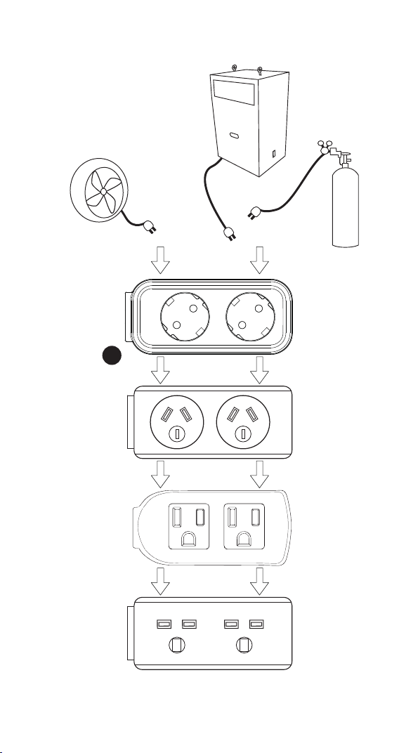
B
WORK2
Exhaust FAN
CO₂ Generator
CO₂ Regulator
WORK1
or
UK
US
AU
EU
8

A Dual Readouts
● PV: In normal mode, the PV window displays the
measured CO₂ concentration; in the setting mode,
the PV window displays the menu code
● SV: In normal mode, the SV window displays the
CO₂ concentration set value; in the setting mode, the
SV window displays the set value.
B Output (WORK1/WORK2)
● WORK1: the CO₂ regulator or generator
● WORK2: the exhaust fan
C Indicator
● The WORK1 indicator is on: WORK1 output
● The WORK2 indicator is on: WORK2 output
D Buttons
For details, see Chapter 2 “Button Instruction”
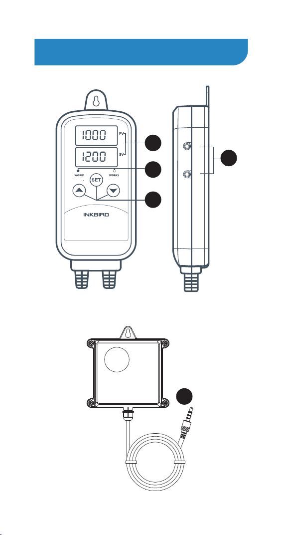
E CO₂ Module interface
CO₂ sensor module can be inserted into P1 or P2
interface
F CO₂ Module
Plugging the CO₂ module into the P1 or P2 interface
1 CO₂ Module Power on Instruction
When the CO₂ module is not inserted, the PV and SV
windows display “----”; when the CO₂ module is
inserted, the controller will take about 8 seconds to
identify. When the CO₂ module is identified to be
inserted, the PV window will display 8888 and blink,
the SV window will display the CO₂ concentration
setting. After 120 seconds, CO₂ module works
stably, and the PV window stops blinking and
displays the measured CO₂ concentration. Within
120 seconds, the buttons cannot be operated , the
indicators of WORK1 and WORK2 are off, and the
WORK1 and WORK2 have no output.
2 Button Instruction
2.1 Restore Factory Settings
Hold the button to power on, and the buzzer will
make a short beep, prompting users to restore all
parameters to factory default settings.
2.2 When TR=1 (Continuous Timer Mode) or 2
(Target Timer Mode), the operation starts from the
first stage of the CO₂ Concentration Setting by
default
When TR=1 or 2, hold the button to power on,
the buzzer will make a short beep. This alerts the
user that the controller will start from the first stage
of the CO₂ concentration setting for controlling.
2.3 Button Instruction in the Normal Working
Mode
2.3.1 TR=0 (Normal Mode)
Short press the button, then the PV window will
display HD, the SV window will display the WORK1
CO₂ Difference; short press the button again, the
PV window will display CD, the SV window will
display the WORK2 CO₂ Difference.
If there is no operation for 3 seconds, the device
will automatically exit the HD and CD mode and
return to the normal display mode, or you can press
the or button to quit the mode directly.
2.3.2 TR=1 (Continuous Timer Mode) or 2 (Target
Timer Mode)
Short press the button firstly, the PV window
will display HD, the SV window will display the
WORK1 CO₂ Difference. Short press the button
secondly, the PV window will display CD, the SV
window will display the WORK2 CO₂ Difference.
Short press the button thirdly, the PV window
will display SX (X=01~12), the SV window will
display the current stage CO₂ concentration
setting. Short press the button fourthly, the PV
window will display the unit of current time HX
(X=01~12), the SV window will display the current
remaining working time. Press the button
fifthly, the PV window will display whether the
current segment is in alarm status UX (X=01~12),
and the SV window will display the current alarm
state.
The device will automatically exit the HD and CD
mode and return to the normal display mode if
there’s no operation for 3 seconds, or you can press
the or button to quit the mode directly.
2.3.3 TR=1 (Continuous Timer Mode) or 2 (Target
Timer Mode)
Press and hold the button for 2 seconds to run
the Starting Segment Setting (SST) forcibly, and the
buzzer will make a short beep at the same time.
2.4 Instruction in the Normal Working Mode
Press the button to enter quick setting mode to
set the CO₂ concentration setting. When TR equals
0, the SV will display the CO₂ concentration setting
and blinks. Short press the or button to
increase or decrease the set value. Long press
the or button to increase or decrease the
set value quickly. Press the button again to
confirm the set value and exit the mode. When TR
equals 1 or 2, press the button to enter the
quick setting mode to set the current segment of
the CO₂ concentration setting, the SV screen will
display the current segment of the CO₂
concentration setting and it will blink, then press
the or button to increase or decrease the
set value. Long press the or button to
increase or decrease the set value quickly. Press
the button secondly to switch to current stage
control duration value, press the or button
to modify the time setting value. Press the
button thirdly to switch to whether to alarm after
the completion of the current segment, press
the or button to modify the setting value.
Press the button fourthly to confirm and exit
the mode. If there is no operation, it will exit the
mode after 30 seconds and save the set value
automatically.
2.5 Buttons Instruction in the Setting Mode
Press and hold the button for 2 seconds to
enter the setting mode. The PV window will display
the code of the first menu item CS, if TR equals 1
or 2, the PV window will display the code of the
second menu item HD, and the SV will display the
corresponding set value. Press the button to
scroll down through the menu items to save the
parameters of the previous menu item. Press
the or button to change the setting value.
If there is no operation for 180 seconds in the
setting mode, the device will exit the mode and
save the setting value automatically and then
return to the normal working mode. You can also
hold the button for 2 seconds to quit the mode
and save the setting value directly.
3 Menu Instruction
3.1 Menu Setting Flowchart
9

Operation Instruction
1 CO₂ Module Power on Instruction
When the CO₂ module is not inserted, the PV and SV
windows display “----”; when the CO₂ module is
inserted, the controller will take about 8 seconds to
identify. When the CO₂ module is identified to be
inserted, the PV window will display 8888 and blink,
the SV window will display the CO₂ concentration
setting. After 120 seconds, CO₂ module works
stably, and the PV window stops blinking and
displays the measured CO₂ concentration. Within
120 seconds, the buttons cannot be operated , the
indicators of WORK1 and WORK2 are off, and the
WORK1 and WORK2 have no output.
2 Button Instruction
2.1 Restore Factory Settings
Hold the button to power on, and the buzzer will
make a short beep, prompting users to restore all
parameters to factory default settings.
2.2 When TR=1 (Continuous Timer Mode) or 2
(Target Timer Mode), the operation starts from the
first stage of the CO₂ Concentration Setting by
default
When TR=1 or 2, hold the button to power on,
the buzzer will make a short beep. This alerts the
user that the controller will start from the first stage
of the CO₂ concentration setting for controlling.
2.3 Button Instruction in the Normal Working
Mode
2.3.1 TR=0 (Normal Mode)
Short press the button, then the PV window will
display HD, the SV window will display the WORK1
CO₂ Difference; short press the button again, the
PV window will display CD, the SV window will
display the WORK2 CO₂ Difference.
If there is no operation for 3 seconds, the device
will automatically exit the HD and CD mode and
return to the normal display mode, or you can press
the or button to quit the mode directly.
2.3.2 TR=1 (Continuous Timer Mode) or 2 (Target
Timer Mode)
Short press the button firstly, the PV window
will display HD, the SV window will display the
WORK1 CO₂ Difference. Short press the button
secondly, the PV window will display CD, the SV
window will display the WORK2 CO₂ Difference.
Short press the button thirdly, the PV window
will display SX (X=01~12), the SV window will
display the current stage CO₂ concentration
setting. Short press the button fourthly, the PV
window will display the unit of current time HX
(X=01~12), the SV window will display the current
remaining working time. Press the button
fifthly, the PV window will display whether the
current segment is in alarm status UX (X=01~12),
and the SV window will display the current alarm
state.
The device will automatically exit the HD and CD
mode and return to the normal display mode if
there’s no operation for 3 seconds, or you can press
the or button to quit the mode directly.
2.3.3 TR=1 (Continuous Timer Mode) or 2 (Target
Timer Mode)
Press and hold the button for 2 seconds to run
the Starting Segment Setting (SST) forcibly, and the
buzzer will make a short beep at the same time.
2.4 Instruction in the Normal Working Mode
Press the button to enter quick setting mode to
set the CO₂ concentration setting. When TR equals
0, the SV will display the CO₂ concentration setting
and blinks. Short press the or button to
increase or decrease the set value. Long press
the or button to increase or decrease the
set value quickly. Press the button again to
confirm the set value and exit the mode. When TR
equals 1 or 2, press the button to enter the
quick setting mode to set the current segment of
the CO₂ concentration setting, the SV screen will
display the current segment of the CO₂
concentration setting and it will blink, then press
the or button to increase or decrease the
set value. Long press the or button to
increase or decrease the set value quickly. Press
the button secondly to switch to current stage
control duration value, press the or button
to modify the time setting value. Press the
button thirdly to switch to whether to alarm after
the completion of the current segment, press
the or button to modify the setting value.
Press the button fourthly to confirm and exit
the mode. If there is no operation, it will exit the
mode after 30 seconds and save the set value
automatically.
2.5 Buttons Instruction in the Setting Mode
Press and hold the button for 2 seconds to
enter the setting mode. The PV window will display
the code of the first menu item CS, if TR equals 1
or 2, the PV window will display the code of the
second menu item HD, and the SV will display the
corresponding set value. Press the button to
scroll down through the menu items to save the
parameters of the previous menu item. Press
the or button to change the setting value.
If there is no operation for 180 seconds in the
setting mode, the device will exit the mode and
save the setting value automatically and then
return to the normal working mode. You can also
hold the button for 2 seconds to quit the mode
and save the setting value directly.
3 Menu Instruction
3.1 Menu Setting Flowchart
10

1 CO₂ Module Power on Instruction
When the CO₂ module is not inserted, the PV and SV
windows display “----”; when the CO₂ module is
inserted, the controller will take about 8 seconds to
identify. When the CO₂ module is identified to be
inserted, the PV window will display 8888 and blink,
the SV window will display the CO₂ concentration
setting. After 120 seconds, CO₂ module works
stably, and the PV window stops blinking and
displays the measured CO₂ concentration. Within
120 seconds, the buttons cannot be operated , the
indicators of WORK1 and WORK2 are off, and the
WORK1 and WORK2 have no output.
2 Button Instruction
2.1 Restore Factory Settings
Hold the button to power on, and the buzzer will
make a short beep, prompting users to restore all
parameters to factory default settings.
2.2 When TR=1 (Continuous Timer Mode) or 2
(Target Timer Mode), the operation starts from the
first stage of the CO₂ Concentration Setting by
default
When TR=1 or 2, hold the button to power on,
the buzzer will make a short beep. This alerts the
user that the controller will start from the first stage
of the CO₂ concentration setting for controlling.
2.3 Button Instruction in the Normal Working
Mode
2.3.1 TR=0 (Normal Mode)
Short press the button, then the PV window will
display HD, the SV window will display the WORK1
CO₂ Difference; short press the button again, the
PV window will display CD, the SV window will
display the WORK2 CO₂ Difference.
If there is no operation for 3 seconds, the device
will automatically exit the HD and CD mode and
return to the normal display mode, or you can press
the or button to quit the mode directly.
2.3.2 TR=1 (Continuous Timer Mode) or 2 (Target
Timer Mode)
Short press the button firstly, the PV window
will display HD, the SV window will display the
WORK1 CO₂ Difference. Short press the button
secondly, the PV window will display CD, the SV
window will display the WORK2 CO₂ Difference.
Short press the button thirdly, the PV window
will display SX (X=01~12), the SV window will
display the current stage CO₂ concentration
setting. Short press the button fourthly, the PV
window will display the unit of current time HX
(X=01~12), the SV window will display the current
remaining working time. Press the button
fifthly, the PV window will display whether the
current segment is in alarm status UX (X=01~12),
and the SV window will display the current alarm
state.
The device will automatically exit the HD and CD
mode and return to the normal display mode if
there’s no operation for 3 seconds, or you can press
the or button to quit the mode directly.
2.3.3 TR=1 (Continuous Timer Mode) or 2 (Target
Timer Mode)
Press and hold the button for 2 seconds to run
the Starting Segment Setting (SST) forcibly, and the
buzzer will make a short beep at the same time.
2.4 Instruction in the Normal Working Mode
Press the button to enter quick setting mode to
set the CO₂ concentration setting. When TR equals
0, the SV will display the CO₂ concentration setting
and blinks. Short press the or button to
increase or decrease the set value. Long press
the or button to increase or decrease the
set value quickly. Press the button again to
confirm the set value and exit the mode. When TR
equals 1 or 2, press the button to enter the
quick setting mode to set the current segment of
the CO₂ concentration setting, the SV screen will
display the current segment of the CO₂
concentration setting and it will blink, then press
the or button to increase or decrease the
set value. Long press the or button to
increase or decrease the set value quickly. Press
the button secondly to switch to current stage
control duration value, press the or button
to modify the time setting value. Press the
button thirdly to switch to whether to alarm after
the completion of the current segment, press
the or button to modify the setting value.
Press the button fourthly to confirm and exit
the mode. If there is no operation, it will exit the
mode after 30 seconds and save the set value
automatically.
2.5 Buttons Instruction in the Setting Mode
Press and hold the button for 2 seconds to
enter the setting mode. The PV window will display
the code of the first menu item CS, if TR equals 1
or 2, the PV window will display the code of the
second menu item HD, and the SV will display the
corresponding set value. Press the button to
scroll down through the menu items to save the
parameters of the previous menu item. Press
the or button to change the setting value.
If there is no operation for 180 seconds in the
setting mode, the device will exit the mode and
save the setting value automatically and then
return to the normal working mode. You can also
hold the button for 2 seconds to quit the mode
and save the setting value directly.
3 Menu Instruction
3.1 Menu Setting Flowchart
SET
SET
SET
SET
11
1 CO₂ Module Power on Instruction
When the CO₂ module is not inserted, the PV and SV
windows display “----”; when the CO₂ module is
inserted, the controller will take about 8 seconds to
identify. When the CO₂ module is identified to be
inserted, the PV window will display 8888 and blink,
the SV window will display the CO₂ concentration
setting. After 120 seconds, CO₂ module works
stably, and the PV window stops blinking and
displays the measured CO₂ concentration. Within
120 seconds, the buttons cannot be operated , the
indicators of WORK1 and WORK2 are off, and the
WORK1 and WORK2 have no output.
2 Button Instruction
2.1 Restore Factory Settings
Hold the button to power on, and the buzzer will
make a short beep, prompting users to restore all
parameters to factory default settings.
2.2 When TR=1 (Continuous Timer Mode) or 2
(Target Timer Mode), the operation starts from the
first stage of the CO₂ Concentration Setting by
default
When TR=1 or 2, hold the button to power on,
the buzzer will make a short beep. This alerts the
user that the controller will start from the first stage
of the CO₂ concentration setting for controlling.
2.3 Button Instruction in the Normal Working
Mode
2.3.1 TR=0 (Normal Mode)
Short press the button, then the PV window will
display HD, the SV window will display the WORK1
CO₂ Difference; short press the button again, the
PV window will display CD, the SV window will
display the WORK2 CO₂ Difference.
If there is no operation for 3 seconds, the device
will automatically exit the HD and CD mode and
return to the normal display mode, or you can press
the or button to quit the mode directly.
2.3.2 TR=1 (Continuous Timer Mode) or 2 (Target
Timer Mode)
Short press the button firstly, the PV window
will display HD, the SV window will display the
WORK1 CO₂ Difference. Short press the button
secondly, the PV window will display CD, the SV
window will display the WORK2 CO₂ Difference.
Short press the button thirdly, the PV window
will display SX (X=01~12), the SV window will
display the current stage CO₂ concentration
setting. Short press the button fourthly, the PV
window will display the unit of current time HX
(X=01~12), the SV window will display the current
remaining working time. Press the button
fifthly, the PV window will display whether the
current segment is in alarm status UX (X=01~12),
and the SV window will display the current alarm
state.
The device will automatically exit the HD and CD
mode and return to the normal display mode if
there’s no operation for 3 seconds, or you can press
the or button to quit the mode directly.
2.3.3 TR=1 (Continuous Timer Mode) or 2 (Target
Timer Mode)
Press and hold the button for 2 seconds to run
the Starting Segment Setting (SST) forcibly, and the
buzzer will make a short beep at the same time.
2.4 Instruction in the Normal Working Mode
Press the button to enter quick setting mode to
set the CO₂ concentration setting. When TR equals
0, the SV will display the CO₂ concentration setting
and blinks. Short press the or button to
increase or decrease the set value. Long press
the or button to increase or decrease the
set value quickly. Press the button again to
confirm the set value and exit the mode. When TR
equals 1 or 2, press the button to enter the
quick setting mode to set the current segment of
the CO₂ concentration setting, the SV screen will
display the current segment of the CO₂
concentration setting and it will blink, then press
the or button to increase or decrease the
set value. Long press the or button to
increase or decrease the set value quickly. Press
the button secondly to switch to current stage
control duration value, press the or button
to modify the time setting value. Press the
button thirdly to switch to whether to alarm after
the completion of the current segment, press
the or button to modify the setting value.
Press the button fourthly to confirm and exit
the mode. If there is no operation, it will exit the
mode after 30 seconds and save the set value
automatically.
2.5 Buttons Instruction in the Setting Mode
Press and hold the button for 2 seconds to
enter the setting mode. The PV window will display
the code of the first menu item CS, if TR equals 1
or 2, the PV window will display the code of the
second menu item HD, and the SV will display the
corresponding set value. Press the button to
scroll down through the menu items to save the
parameters of the previous menu item. Press
the or button to change the setting value.
If there is no operation for 180 seconds in the
setting mode, the device will exit the mode and
save the setting value automatically and then
return to the normal working mode. You can also
hold the button for 2 seconds to quit the mode
and save the setting value directly.
3 Menu Instruction
3.1 Menu Setting Flowchart
SET
SET
SET
SET
SET
SET
SET
12
1 CO₂ Module Power on Instruction
When the CO₂ module is not inserted, the PV and SV
windows display “----”; when the CO₂ module is
inserted, the controller will take about 8 seconds to
identify. When the CO₂ module is identified to be
inserted, the PV window will display 8888 and blink,
the SV window will display the CO₂ concentration
setting. After 120 seconds, CO₂ module works
stably, and the PV window stops blinking and
displays the measured CO₂ concentration. Within
120 seconds, the buttons cannot be operated , the
indicators of WORK1 and WORK2 are off, and the
WORK1 and WORK2 have no output.
2 Button Instruction
2.1 Restore Factory Settings
Hold the button to power on, and the buzzer will
make a short beep, prompting users to restore all
parameters to factory default settings.
2.2 When TR=1 (Continuous Timer Mode) or 2
(Target Timer Mode), the operation starts from the
first stage of the CO₂ Concentration Setting by
default
When TR=1 or 2, hold the button to power on,
the buzzer will make a short beep. This alerts the
user that the controller will start from the first stage
of the CO₂ concentration setting for controlling.
2.3 Button Instruction in the Normal Working
Mode
2.3.1 TR=0 (Normal Mode)
Short press the button, then the PV window will
display HD, the SV window will display the WORK1
CO₂ Difference; short press the button again, the
PV window will display CD, the SV window will
display the WORK2 CO₂ Difference.
If there is no operation for 3 seconds, the device
will automatically exit the HD and CD mode and
return to the normal display mode, or you can press
the or button to quit the mode directly.
2.3.2 TR=1 (Continuous Timer Mode) or 2 (Target
Timer Mode)
Short press the button firstly, the PV window
will display HD, the SV window will display the
WORK1 CO₂ Difference. Short press the button
secondly, the PV window will display CD, the SV
window will display the WORK2 CO₂ Difference.
Short press the button thirdly, the PV window
will display SX (X=01~12), the SV window will
display the current stage CO₂ concentration
setting. Short press the button fourthly, the PV
window will display the unit of current time HX
(X=01~12), the SV window will display the current
remaining working time. Press the button
fifthly, the PV window will display whether the
current segment is in alarm status UX (X=01~12),
and the SV window will display the current alarm
state.
The device will automatically exit the HD and CD
mode and return to the normal display mode if
there’s no operation for 3 seconds, or you can press
the or button to quit the mode directly.
2.3.3 TR=1 (Continuous Timer Mode) or 2 (Target
Timer Mode)
Press and hold the button for 2 seconds to run
the Starting Segment Setting (SST) forcibly, and the
buzzer will make a short beep at the same time.
2.4 Instruction in the Normal Working Mode
Press the button to enter quick setting mode to
set the CO₂ concentration setting. When TR equals
0, the SV will display the CO₂ concentration setting
and blinks. Short press the or button to
increase or decrease the set value. Long press
the or button to increase or decrease the
set value quickly. Press the button again to
confirm the set value and exit the mode. When TR
equals 1 or 2, press the button to enter the
quick setting mode to set the current segment of
the CO₂ concentration setting, the SV screen will
display the current segment of the CO₂
concentration setting and it will blink, then press
the or button to increase or decrease the
set value. Long press the or button to
increase or decrease the set value quickly. Press
the button secondly to switch to current stage
control duration value, press the or button
to modify the time setting value. Press the
button thirdly to switch to whether to alarm after
the completion of the current segment, press
the or button to modify the setting value.
Press the button fourthly to confirm and exit
the mode. If there is no operation, it will exit the
mode after 30 seconds and save the set value
automatically.
2.5 Buttons Instruction in the Setting Mode
Press and hold the button for 2 seconds to
enter the setting mode. The PV window will display
the code of the first menu item CS, if TR equals 1
or 2, the PV window will display the code of the
second menu item HD, and the SV will display the
corresponding set value. Press the button to
scroll down through the menu items to save the
parameters of the previous menu item. Press
the or button to change the setting value.
If there is no operation for 180 seconds in the
setting mode, the device will exit the mode and
save the setting value automatically and then
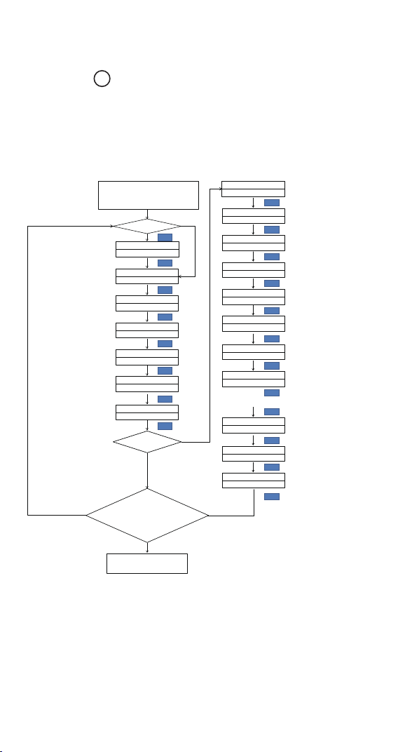
N
Y
CO₂ Concentration
Setting
TR = 0 ?
CS
1200ppm
HD
300ppm
Press "SET" Key for over 2
seconds to enter parameters
setting mode
WORK1 CO₂ Difference
WORK2 CO₂ Difference
High CO₂
Concentration Alarm
Low CO₂
Concentration Alarm
CO₂ Calibration
Alarm sound in
the alarm state
TR=0->Normal Mode
TR=1->Continuous Timer Mode
TR=2->Target Timer Mode
Y
Y
N
N
SET
SET
CD
300ppm
SET
AH
5000ppm
SET
AL
300ppm
SET
CA
0ppm
SET
ALM
ON
SET
SET
Unit of Time: D (day),
H (Hour), M (Minute)
UT
M
MD
1
Cycel Times Setting: 1~999,
MD=0 for infinite cycle
Manual or Automatic
Time Period Setting: 1~12
Starting Segment Setting
Segment1: CO₂
concentration setting
Segment1: Continuous
Control Time
Segment1: Alarm or not
Segment12: CO₂
Concentration Setting
Segment12: Continuous
Control Time
Segment12: Alarm or not
n: No Aleat
A: Alert
C: Confirm
S: Stop
SET
AT
0
SET
STT
1
SET
SST
1
SET
CS01
1200ppm
SET
H01
10
SET
U01
n
……
SET
SET
CS12
1200ppm
SET
H12
10
SET
U12
n
SET
SET
TR=1or2?
No button for 180 seconds
or Presss “SET” key for
over 2 second?
Working normally
return to the normal working mode. You can also
hold the button for 2 seconds to quit the mode
and save the setting value directly.
3 Menu Instruction
3.1 Menu Setting Flowchart
SET
13
3.2 Menu Setting Instruction
1 CO₂ Module Power on Instruction
When the CO₂ module is not inserted, the PV and SV
windows display “----”; when the CO₂ module is
inserted, the controller will take about 8 seconds to
identify. When the CO₂ module is identified to be
inserted, the PV window will display 8888 and blink,
the SV window will display the CO₂ concentration
setting. After 120 seconds, CO₂ module works
stably, and the PV window stops blinking and
displays the measured CO₂ concentration. Within
120 seconds, the buttons cannot be operated , the
indicators of WORK1 and WORK2 are off, and the
WORK1 and WORK2 have no output.
2 Button Instruction
2.1 Restore Factory Settings
Hold the button to power on, and the buzzer will
make a short beep, prompting users to restore all
parameters to factory default settings.
2.2 When TR=1 (Continuous Timer Mode) or 2
(Target Timer Mode), the operation starts from the
first stage of the CO₂ Concentration Setting by
default
When TR=1 or 2, hold the button to power on,
the buzzer will make a short beep. This alerts the
user that the controller will start from the first stage
of the CO₂ concentration setting for controlling.
2.3 Button Instruction in the Normal Working
Mode
2.3.1 TR=0 (Normal Mode)
Short press the button, then the PV window will
display HD, the SV window will display the WORK1
CO₂ Difference; short press the button again, the
PV window will display CD, the SV window will
display the WORK2 CO₂ Difference.
If there is no operation for 3 seconds, the device
will automatically exit the HD and CD mode and
return to the normal display mode, or you can press
the or button to quit the mode directly.
2.3.2 TR=1 (Continuous Timer Mode) or 2 (Target
Timer Mode)
Short press the button firstly, the PV window
will display HD, the SV window will display the
WORK1 CO₂ Difference. Short press the button
secondly, the PV window will display CD, the SV
window will display the WORK2 CO₂ Difference.
Short press the button thirdly, the PV window
will display SX (X=01~12), the SV window will
display the current stage CO₂ concentration
setting. Short press the button fourthly, the PV
window will display the unit of current time HX
(X=01~12), the SV window will display the current
remaining working time. Press the button
fifthly, the PV window will display whether the
current segment is in alarm status UX (X=01~12),
and the SV window will display the current alarm
state.
The device will automatically exit the HD and CD
mode and return to the normal display mode if
there’s no operation for 3 seconds, or you can press
the or button to quit the mode directly.
2.3.3 TR=1 (Continuous Timer Mode) or 2 (Target
Timer Mode)
Press and hold the button for 2 seconds to run
the Starting Segment Setting (SST) forcibly, and the
buzzer will make a short beep at the same time.
2.4 Instruction in the Normal Working Mode
Press the button to enter quick setting mode to
set the CO₂ concentration setting. When TR equals
0, the SV will display the CO₂ concentration setting
and blinks. Short press the or button to
increase or decrease the set value. Long press
the or button to increase or decrease the
set value quickly. Press the button again to
confirm the set value and exit the mode. When TR
equals 1 or 2, press the button to enter the
quick setting mode to set the current segment of
the CO₂ concentration setting, the SV screen will
display the current segment of the CO₂
concentration setting and it will blink, then press
the or button to increase or decrease the
set value. Long press the or button to
increase or decrease the set value quickly. Press
the button secondly to switch to current stage
control duration value, press the or button
to modify the time setting value. Press the
button thirdly to switch to whether to alarm after
the completion of the current segment, press
the or button to modify the setting value.
Press the button fourthly to confirm and exit
the mode. If there is no operation, it will exit the
mode after 30 seconds and save the set value
automatically.
2.5 Buttons Instruction in the Setting Mode
Press and hold the button for 2 seconds to
enter the setting mode. The PV window will display
the code of the first menu item CS, if TR equals 1
or 2, the PV window will display the code of the
second menu item HD, and the SV will display the
corresponding set value. Press the button to
scroll down through the menu items to save the
parameters of the previous menu item. Press
the or button to change the setting value.
If there is no operation for 180 seconds in the
setting mode, the device will exit the mode and
save the setting value automatically and then
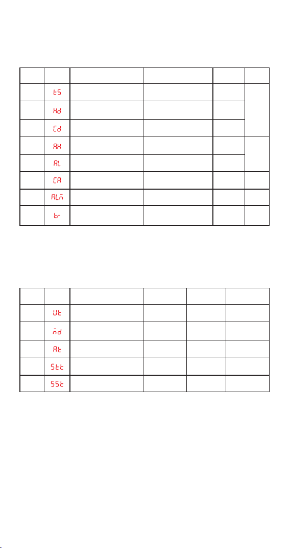
Menu
Items
CS
HD
CD
AH
AL
CA
ALM
TR
CO₂ Concentration Setting
WORK1 CO₂ Difference
WORK2 CO₂ Difference
High CO₂ Concentration
Alarm
Low CO₂ Concentration
Alarm
CO₂ Calibration
Alarm Sound in
the alarm state
Timer Mode
0~9999ppm
10~2000ppm
10~2000ppm
0~9999ppm
0~9999ppm
-500~500ppm
ON/OFF
0->Normal Mode,
1->Continuous Timer Mode,
2->Target Timer Mode
1200ppm
300ppm
300ppm
5000ppm
300ppm
0ppm
ON
0
See 4.1
See 4.2
See 4.3
See 4.4
See 4.6
Display
Content
Description Setting Range Default Set Note
3.2.1 Menu Setting Instruction when TR=1
(Continuous Timer Mode) or 2 (Target Timer Mode)
return to the normal working mode. You can also
hold the button for 2 seconds to quit the mode
and save the setting value directly.
3 Menu Instruction
3.1 Menu Setting Flowchart
Menu
Items
UT
MD
AT
STT
SST
Unit of time
Cycle Times Setting
Manual or Automatic Mode
Time Period Setting
Starting Segment Setting
D, H, M
0~999
0~1
1~12
1~12
D
1
0
1
1
D: Day; H: Hour;
M: Minute
See 4.6.5
for details
See 4.6.4
for details
0-> Manual
1-> Automatic
When MD=0,
infinite loop
Display
Content
Description Setting Range Default Set Note
14
1 CO₂ Module Power on Instruction
When the CO₂ module is not inserted, the PV and SV
windows display “----”; when the CO₂ module is
inserted, the controller will take about 8 seconds to
identify. When the CO₂ module is identified to be
inserted, the PV window will display 8888 and blink,
the SV window will display the CO₂ concentration
setting. After 120 seconds, CO₂ module works
stably, and the PV window stops blinking and
displays the measured CO₂ concentration. Within
120 seconds, the buttons cannot be operated , the
indicators of WORK1 and WORK2 are off, and the
WORK1 and WORK2 have no output.
2 Button Instruction
2.1 Restore Factory Settings
Hold the button to power on, and the buzzer will
make a short beep, prompting users to restore all
parameters to factory default settings.
2.2 When TR=1 (Continuous Timer Mode) or 2
(Target Timer Mode), the operation starts from the
first stage of the CO₂ Concentration Setting by
default
When TR=1 or 2, hold the button to power on,
the buzzer will make a short beep. This alerts the
user that the controller will start from the first stage
of the CO₂ concentration setting for controlling.
2.3 Button Instruction in the Normal Working
Mode
2.3.1 TR=0 (Normal Mode)
Short press the button, then the PV window will
display HD, the SV window will display the WORK1
CO₂ Difference; short press the button again, the
PV window will display CD, the SV window will
display the WORK2 CO₂ Difference.
If there is no operation for 3 seconds, the device
will automatically exit the HD and CD mode and
return to the normal display mode, or you can press
the or button to quit the mode directly.
2.3.2 TR=1 (Continuous Timer Mode) or 2 (Target
Timer Mode)
Short press the button firstly, the PV window
will display HD, the SV window will display the
WORK1 CO₂ Difference. Short press the button
secondly, the PV window will display CD, the SV
window will display the WORK2 CO₂ Difference.
Short press the button thirdly, the PV window
will display SX (X=01~12), the SV window will
display the current stage CO₂ concentration
setting. Short press the button fourthly, the PV
window will display the unit of current time HX
(X=01~12), the SV window will display the current
remaining working time. Press the button
fifthly, the PV window will display whether the
current segment is in alarm status UX (X=01~12),
and the SV window will display the current alarm
state.
The device will automatically exit the HD and CD
mode and return to the normal display mode if
there’s no operation for 3 seconds, or you can press
the or button to quit the mode directly.
2.3.3 TR=1 (Continuous Timer Mode) or 2 (Target
Timer Mode)
Press and hold the button for 2 seconds to run
the Starting Segment Setting (SST) forcibly, and the
buzzer will make a short beep at the same time.
2.4 Instruction in the Normal Working Mode
Press the button to enter quick setting mode to
set the CO₂ concentration setting. When TR equals
0, the SV will display the CO₂ concentration setting
and blinks. Short press the or button to
increase or decrease the set value. Long press
the or button to increase or decrease the
set value quickly. Press the button again to
confirm the set value and exit the mode. When TR
equals 1 or 2, press the button to enter the
quick setting mode to set the current segment of
the CO₂ concentration setting, the SV screen will
display the current segment of the CO₂
concentration setting and it will blink, then press
the or button to increase or decrease the
set value. Long press the or button to
increase or decrease the set value quickly. Press
the button secondly to switch to current stage
control duration value, press the or button
to modify the time setting value. Press the
button thirdly to switch to whether to alarm after
the completion of the current segment, press
the or button to modify the setting value.
Press the button fourthly to confirm and exit
the mode. If there is no operation, it will exit the
mode after 30 seconds and save the set value
automatically.
2.5 Buttons Instruction in the Setting Mode
Press and hold the button for 2 seconds to
enter the setting mode. The PV window will display
the code of the first menu item CS, if TR equals 1
or 2, the PV window will display the code of the
second menu item HD, and the SV will display the
corresponding set value. Press the button to
scroll down through the menu items to save the
parameters of the previous menu item. Press
the or button to change the setting value.
If there is no operation for 180 seconds in the
setting mode, the device will exit the mode and
save the setting value automatically and then
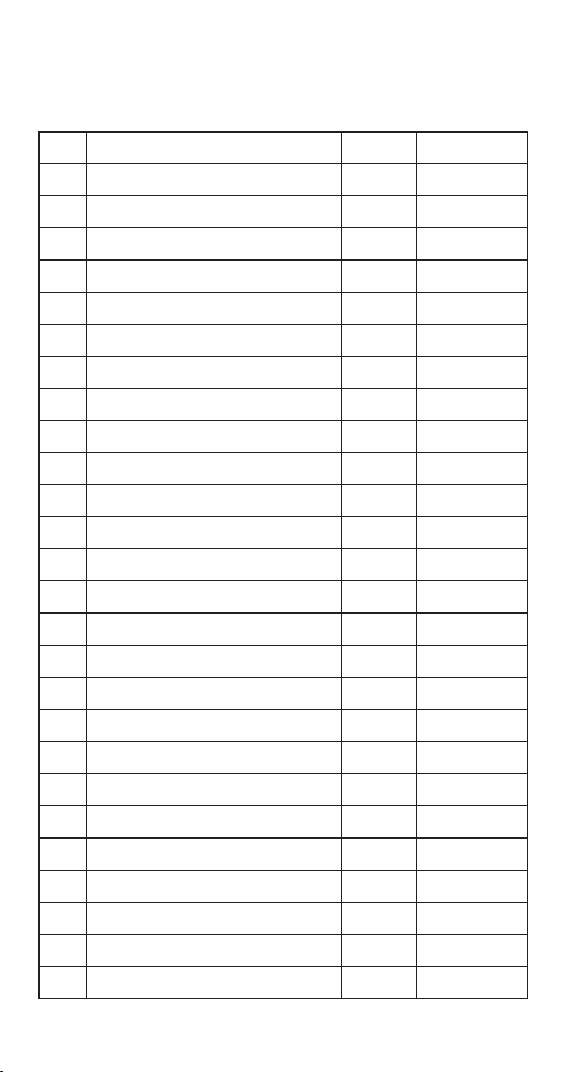
3.2.2 Menu Setting Instruction when the STT is 12
Menu
Items
S01
H01
U01
S02
H02
U02
S03
H03
The First Segment of the CO₂ Concentration Setting
The First Segment of the Continuous Control Time
Alarm or not after the First Segment
The Second Segment of the CO₂ Concentration Setting
The Second Segment of the Continuous Control Time
Alarm or not after the Second Segment
The Third Segment of the CO₂ Concentration Setting
The Third Segment of the Continuous Control Time
1200ppm
10 d: 1~90, H&M: 1~999
n
1200ppm
10
n
1200ppm
10
U03 Alarm or not after the Third Segment n
n=No Alert, A=Alert,
C=Confirm, S=Stop
d: 1~90, H&M: 1~999
n=No Alert, A=Alert,
C=Confirm, S=Stop
d: 1~90, H&M: 1~999
n=No Alert, A=Alert,
C=Confirm, S=Stop
d: 1~90, H&M: 1~999
n=No Alert, A=Alert,
C=Confirm, S=Stop
d: 1~90, H&M: 1~999
n=No Alert, A=Alert,
C=Confirm, S=Stop
d: 1~90, H&M: 1~999
n=No Alert, A=Alert,
C=Confirm, S=Stop
d: 1~90, H&M: 1~999
n=No Alert, A=Alert,
C=Confirm, S=Stop
d: 1~90, H&M: 1~999
d: 1~90, H&M: 1~999
n=No Alert, A=Alert,
C=Confirm, S=Stop
Description Default Set Note
S04
H04
U04
S05
H05
U05
S06
H06
The Fourth Segment of the CO₂ Concentration Setting
The Fourth Segment of the Continuous Control Time
Alarm or not after the Fourth Segment
The Fifth Segment of the CO₂ Concentration Setting
The Fifth Segment of the Continuous Control Time
Alarm or not after the Fifth Segment
The Sixth Segment of the CO₂ Concentration Setting
The Sixth Segment of the Continuous Control Time
1200ppm
10
n
1200ppm
10
n
1200ppm
10
U06 Alarm or not after the Sixth Segment n
S07
H07
U07
S08
H08
U08
S09
H09
The Seventh Segment of the CO₂ Concentration Setting
The Seventh Segment of the Continuous Control Time
Alarm or not after the Seventh Segment
The Eighth Segment of the CO₂ Concentration Setting
The Eighth Segment of the Continuous Control Time
Alarm or not after the Eighth Segment
The Ninth Segment of the CO₂ Concentration Setting
The Ninth Segment of the Continuous Control Time
1200ppm
10
n
1200ppm
10
n
1200ppm
10
return to the normal working mode. You can also
hold the button for 2 seconds to quit the mode
and save the setting value directly.
3 Menu Instruction
3.1 Menu Setting Flowchart
15

will return to the normal CO₂ concentration setting
control.
The CO₂ regulator or generator will be turned on when
the measured CO₂ concentration < 1200ppm (CS), the
CO₂ regulator or generator will be turned off when the
measured CO₂ concentration ≥ 1200 ppm (CS), then
the controller will return to the normal CO₂
concentration setting control.
4.1.2 Continuous Timer Mode When TR=1
The CS setting value will be invalid. The controller will
execute the command according to the setting values
of S01~S12, H01~H12, and U01~U12, the continuous
running time starts from Starting Segment Setting
(SST).
For more information about time-CO₂ Concentration
Setting control, please refer to 4.5
4.1.3 Target Timer Mode when TR=2
The CS setting value will be invalid. The controller will
execute the command according to the setting values
of S01~S12, H01~H12, and U01~U12, the continuous
running time starts counting only when the CO₂
concentration reaches the current segment of the CO₂
concentration setting (S01~S12), the SV window will
flash at a frequency of 0.5 Hz before the counting
start.
For more information about time-CO₂ Concentration
Setting control, please refer to 4.5
4.2 High and Low CO₂ Concentration Alarm (AH, AL)
When the measured CO₂ concentration ≥ High CO₂
Concentration Alarm (AH), the PV window will display
AH and the measured CO₂ concentration alternately
at the 1Hz frequency. If ALM=ON, the buzzer will
alarm “Bi-Bi-Biii“ until the measured CO₂
concentration < High CO₂ Concentration Alarm (AH),
then the buzzer will turn off and the device will revert
back to normal display and normal control. No
matter which button is pressed, the buzzer alarm
sound will be turned off only.
When the measured CO₂ concentration ≤ Low CO₂
Concentration Alarm (AL), the PV window will
display AL and the measured CO₂ concentration
alternately at the 1Hz frequency. If ALM=ON, the
buzzer will alarm “Bi-Bi-Biii” until the measured CO2
concentration > Low CO₂ Concentration Alarm (AL),
then the buzzer will turn off and the device will
revert back to normal display and normal control.
No matter which button is pressed, only the buzzer
alarm sound will be turned off.
4.3 CO₂ Calibration (CA)
When there is a difference between the measured
CO₂ concentration and the actual CO₂ concentration,
you can adjust the CO₂ concentration calibration to
make the measured value of the instrument
consistent with the actual value. The corrected CO2
concentration value=the measured CO₂
concentration+CO₂ calibration.
4.4 Whether the buzzer is turned on during
abnormal alarm (ALM)
Users can choose whether the buzzer sounds when
abnormal alarm occurs. When ON is selected, the
buzzer will sound when it is abnormal; when OFF is
selected, the buzzer will not sound when it is
abnormal.
4.5 The Time-CO₂ Concentration Setting
Parameters Instruction (MD, TR, UT, STT, SST,
S01~S12, H01~H12, U01~U12)
4.5.1 MD is the Cycle Times Setting of the
Time-CO₂ Concentration Setting, it runs from the
Starting Segment Setting (SST) to the Time Period
Setting (STT) in a cycle. If MD=0 means infinite
loop, MD=1~999 means the specific number of
loops executed.
The default value of MD is 1. Under the condition of
MD=1~999, after executing the cycle times, the
detailed status is described in 4.5.8.
4.5.2 TR is the parameter of whether the timer
function is enabled, 0 is off, 1 or 2 is on.
4.5.2.1 TR=0 (Normal Mode), CO₂ Concentration
Setting Normal Control Mode
No setting is required when the timer function is
not activated. All setting parameters after
parameter TR will not appear in the menu.
4.5.2.2 TR=1 (Continuous Timer Mode) & TR=2
(Target Timer Mode)
Users can set the Time-CO₂ Concentration Setting
parameters according to your own needs. At this
time, CS will be invalid and the system will control
according to the segment of the CO₂ concentration
setting (S01~S12).
The following table illustrates the differences
between TR=1 (Continuous Timer Mode) and TR=2
(Target Timer Mode):
4 Control Instrunction
If the controller works normally, the PV window will
display the measured CO₂ concentration, the SV
window will display the CO₂ concentration setting.
The controller will automatically identify and
convert the CO₂ regulator or generator and the
exhaust fan. WORK1 is the output of the CO₂
regulator or generator, and the WORK1 indicator is
the WORK1 output status indicator. WORK2 is the
output of the exhaust fan, and the WORK2 indicator
is the WORK2 output status indicator.
4.1 The CO₂ Concentration Setting Control
Instruction (CS, HD, CD, S01~S12)
4.1.1 The CO₂ Concentration Setting Control
Instruction when TR=0 (Normal Mode)
4.1.1.1 The normal CO₂ Concentration Setting
Control:
When the measured CO₂ concentration ≤ the CO₂
concentration setting (CS)-the WORK1 CO₂
Difference (HD), the WORK1 indicator is on, WORK1
has output and the CO₂ regulator or generator is
turned on. When the measured CO₂ concentration ≥
the CO₂ concentration setting (CS), WORK1 indicator
is off, the WORK1 has no output and indicates to turn
off of the CO₂ regulator or generator.
When the measured CO₂ concentration ≥ the CO₂
concentration setting (CS) + the WORK2 CO₂
Difference (CD), the WORK2 indicator is on, WORK2
has output, and an exhaust fan is turned on; when the
measured CO₂ concentration ≤ the CO₂ concentration
setting (CS), WORK2 indicator is off, WORK2 has no
output, turn off the exhaust fan.
For example, set CS=1200 ppm, HD=200 ppm,
CD=200 ppm, when and the measured CO₂
concentration ≥ 1400 ppm (CS+CD), the exhaust fan
will be turned on; When the measured CO₂
concentration ≤ 1200 ppm (CS), the exhaust fan will
be turned off.
When the measured CO₂ concentration ≤ 1000ppm
(CS-HD), the CO₂ regulator or generator will be
turned on; When the measured CO₂ concentration≥
1200ppm (CS), the CO₂ regulator or generator will be
turned off.
4.1.1.2 The special CO₂ Concentration Setting
Control:
When TR=0 (Normal Mode), if the controller is
powered on or exits the setting state, there is no need
to judge the WORK1 CO₂ Difference (HD) or the
WORK2 CO₂ Difference (CD). It can be directly
compared with the CO₂ Concentration Setting (CS).
For example: when powering on or exiting the setting,
CS=1200 ppm, HD=200 ppm, CD=200 ppm. The
exhaust fan will be turned on when the measured CO₂
concentration > 1200 ppm (CS) and the exhaust fan
will be turned off when the measured CO₂
concentration ≤ 1200 ppm (CS), then the controller
d: 1~90, H&M: 1~999
n=No Alert, A=Alert,
C=Confirm, S=Stop
d: 1~90, H&M: 1~999
n=No Alert, A=Alert,
C=Confirm, S=Stop
d: 1~90, H&M: 1~999
n=No Alert, A=Alert,
C=Confirm, S=Stop
n=No Alert, A=Alert,
C=Confirm, S=Stop
U09
S10
H10
U10
S11
H11
Alarm or not after the Ninth Segment
The Tenth Segment of the CO₂ Concentration Setting
The Tenth Segment of the Continuous Control Time
Alarm or not after the Tenth Segment
The Eleventh Segment of the CO₂Concentration Setting
The Eleventh Segment of the Continuous Control Time
n
1200ppm
10
n
1200ppm
10
U11 Alarm or not after the Eleventh Segment n
S12
H12
U12
The Twelfth Segment of the CO₂ Concentration Setting
The Twelfth Segment of the Continuous Control Time
Alarm or not after the Twelfth Segment
1200ppm
10
n
16

will return to the normal CO₂ concentration setting
control.
The CO₂ regulator or generator will be turned on when
the measured CO₂ concentration < 1200ppm (CS), the
CO₂ regulator or generator will be turned off when the
measured CO₂ concentration ≥ 1200 ppm (CS), then
the controller will return to the normal CO₂
concentration setting control.
4.1.2 Continuous Timer Mode When TR=1
The CS setting value will be invalid. The controller will
execute the command according to the setting values
of S01~S12, H01~H12, and U01~U12, the continuous
running time starts from Starting Segment Setting
(SST).
For more information about time-CO₂ Concentration
Setting control, please refer to 4.5
4.1.3 Target Timer Mode when TR=2
The CS setting value will be invalid. The controller will
execute the command according to the setting values
of S01~S12, H01~H12, and U01~U12, the continuous
running time starts counting only when the CO₂
concentration reaches the current segment of the CO₂
concentration setting (S01~S12), the SV window will
flash at a frequency of 0.5 Hz before the counting
start.
For more information about time-CO₂ Concentration
Setting control, please refer to 4.5
4.2 High and Low CO₂ Concentration Alarm (AH, AL)
When the measured CO₂ concentration ≥ High CO₂
Concentration Alarm (AH), the PV window will display
AH and the measured CO₂ concentration alternately
at the 1Hz frequency. If ALM=ON, the buzzer will
alarm “Bi-Bi-Biii“ until the measured CO₂
concentration < High CO₂ Concentration Alarm (AH),
then the buzzer will turn off and the device will revert
back to normal display and normal control. No
matter which button is pressed, the buzzer alarm
sound will be turned off only.
When the measured CO₂ concentration ≤ Low CO₂
Concentration Alarm (AL), the PV window will
display AL and the measured CO₂ concentration
alternately at the 1Hz frequency. If ALM=ON, the
buzzer will alarm “Bi-Bi-Biii” until the measured CO2
concentration > Low CO₂ Concentration Alarm (AL),
then the buzzer will turn off and the device will
revert back to normal display and normal control.
No matter which button is pressed, only the buzzer
alarm sound will be turned off.
4.3 CO₂ Calibration (CA)
When there is a difference between the measured
CO₂ concentration and the actual CO₂ concentration,
you can adjust the CO₂ concentration calibration to
make the measured value of the instrument
consistent with the actual value. The corrected CO2
concentration value=the measured CO₂
concentration+CO₂ calibration.
4.4 Whether the buzzer is turned on during
abnormal alarm (ALM)
Users can choose whether the buzzer sounds when
abnormal alarm occurs. When ON is selected, the
buzzer will sound when it is abnormal; when OFF is
selected, the buzzer will not sound when it is
abnormal.
4.5 The Time-CO₂ Concentration Setting
Parameters Instruction (MD, TR, UT, STT, SST,
S01~S12, H01~H12, U01~U12)
4.5.1 MD is the Cycle Times Setting of the
Time-CO₂ Concentration Setting, it runs from the
Starting Segment Setting (SST) to the Time Period
Setting (STT) in a cycle. If MD=0 means infinite
loop, MD=1~999 means the specific number of
loops executed.
The default value of MD is 1. Under the condition of
MD=1~999, after executing the cycle times, the
detailed status is described in 4.5.8.
4.5.2 TR is the parameter of whether the timer
function is enabled, 0 is off, 1 or 2 is on.
4.5.2.1 TR=0 (Normal Mode), CO₂ Concentration
Setting Normal Control Mode
No setting is required when the timer function is
not activated. All setting parameters after
parameter TR will not appear in the menu.
4.5.2.2 TR=1 (Continuous Timer Mode) & TR=2
(Target Timer Mode)
Users can set the Time-CO₂ Concentration Setting
parameters according to your own needs. At this
time, CS will be invalid and the system will control
according to the segment of the CO₂ concentration
setting (S01~S12).
The following table illustrates the differences
between TR=1 (Continuous Timer Mode) and TR=2
(Target Timer Mode):
4 Control Instrunction
If the controller works normally, the PV window will
display the measured CO₂ concentration, the SV
window will display the CO₂ concentration setting.
The controller will automatically identify and
convert the CO₂ regulator or generator and the
exhaust fan. WORK1 is the output of the CO₂
regulator or generator, and the WORK1 indicator is
the WORK1 output status indicator. WORK2 is the
output of the exhaust fan, and the WORK2 indicator
is the WORK2 output status indicator.
4.1 The CO₂ Concentration Setting Control
Instruction (CS, HD, CD, S01~S12)
4.1.1 The CO₂ Concentration Setting Control
Instruction when TR=0 (Normal Mode)
4.1.1.1 The normal CO₂ Concentration Setting
Control:
When the measured CO₂ concentration ≤ the CO₂
concentration setting (CS)-the WORK1 CO₂
Difference (HD), the WORK1 indicator is on, WORK1
has output and the CO₂ regulator or generator is
turned on. When the measured CO₂ concentration ≥
the CO₂ concentration setting (CS), WORK1 indicator
is off, the WORK1 has no output and indicates to turn
off of the CO₂ regulator or generator.
When the measured CO₂ concentration ≥ the CO₂
concentration setting (CS) + the WORK2 CO₂
Difference (CD), the WORK2 indicator is on, WORK2
has output, and an exhaust fan is turned on; when the
measured CO₂ concentration ≤ the CO₂ concentration
setting (CS), WORK2 indicator is off, WORK2 has no
output, turn off the exhaust fan.
For example, set CS=1200 ppm, HD=200 ppm,
CD=200 ppm, when and the measured CO₂
concentration ≥ 1400 ppm (CS+CD), the exhaust fan
will be turned on; When the measured CO₂
concentration ≤ 1200 ppm (CS), the exhaust fan will
be turned off.
When the measured CO₂ concentration ≤ 1000ppm
(CS-HD), the CO₂ regulator or generator will be
turned on; When the measured CO₂ concentration≥
1200ppm (CS), the CO₂ regulator or generator will be
turned off.
4.1.1.2 The special CO₂ Concentration Setting
Control:
When TR=0 (Normal Mode), if the controller is
powered on or exits the setting state, there is no need
to judge the WORK1 CO₂ Difference (HD) or the
WORK2 CO₂ Difference (CD). It can be directly
compared with the CO₂ Concentration Setting (CS).
For example: when powering on or exiting the setting,
CS=1200 ppm, HD=200 ppm, CD=200 ppm. The
exhaust fan will be turned on when the measured CO₂
concentration > 1200 ppm (CS) and the exhaust fan
will be turned off when the measured CO₂
concentration ≤ 1200 ppm (CS), then the controller
17

will return to the normal CO₂ concentration setting
control.
The CO₂ regulator or generator will be turned on when
the measured CO₂ concentration < 1200ppm (CS), the
CO₂ regulator or generator will be turned off when the
measured CO₂ concentration ≥ 1200 ppm (CS), then
the controller will return to the normal CO₂
concentration setting control.
4.1.2 Continuous Timer Mode When TR=1
The CS setting value will be invalid. The controller will
execute the command according to the setting values
of S01~S12, H01~H12, and U01~U12, the continuous
running time starts from Starting Segment Setting
(SST).
For more information about time-CO₂ Concentration
Setting control, please refer to 4.5
4.1.3 Target Timer Mode when TR=2
The CS setting value will be invalid. The controller will
execute the command according to the setting values
of S01~S12, H01~H12, and U01~U12, the continuous
running time starts counting only when the CO₂
concentration reaches the current segment of the CO₂
concentration setting (S01~S12), the SV window will
flash at a frequency of 0.5 Hz before the counting
start.
For more information about time-CO₂ Concentration
Setting control, please refer to 4.5
4.2 High and Low CO₂ Concentration Alarm (AH, AL)
When the measured CO₂ concentration ≥ High CO₂
Concentration Alarm (AH), the PV window will display
AH and the measured CO₂ concentration alternately
at the 1Hz frequency. If ALM=ON, the buzzer will
alarm “Bi-Bi-Biii“ until the measured CO₂
concentration < High CO₂ Concentration Alarm (AH),
then the buzzer will turn off and the device will revert
back to normal display and normal control. No
matter which button is pressed, the buzzer alarm
sound will be turned off only.
When the measured CO₂ concentration ≤ Low CO₂
Concentration Alarm (AL), the PV window will
display AL and the measured CO₂ concentration
alternately at the 1Hz frequency. If ALM=ON, the
buzzer will alarm “Bi-Bi-Biii” until the measured CO2
concentration > Low CO₂ Concentration Alarm (AL),
then the buzzer will turn off and the device will
revert back to normal display and normal control.
No matter which button is pressed, only the buzzer
alarm sound will be turned off.
4.3 CO₂ Calibration (CA)
When there is a difference between the measured
CO₂ concentration and the actual CO₂ concentration,
you can adjust the CO₂ concentration calibration to
make the measured value of the instrument
consistent with the actual value. The corrected CO2
concentration value=the measured CO₂
concentration+CO₂ calibration.
4.4 Whether the buzzer is turned on during
abnormal alarm (ALM)
Users can choose whether the buzzer sounds when
abnormal alarm occurs. When ON is selected, the
buzzer will sound when it is abnormal; when OFF is
selected, the buzzer will not sound when it is
abnormal.
4.5 The Time-CO₂ Concentration Setting
Parameters Instruction (MD, TR, UT, STT, SST,
S01~S12, H01~H12, U01~U12)
4.5.1 MD is the Cycle Times Setting of the
Time-CO₂ Concentration Setting, it runs from the
Starting Segment Setting (SST) to the Time Period
Setting (STT) in a cycle. If MD=0 means infinite
loop, MD=1~999 means the specific number of
loops executed.
The default value of MD is 1. Under the condition of
MD=1~999, after executing the cycle times, the
detailed status is described in 4.5.8.
4.5.2 TR is the parameter of whether the timer
function is enabled, 0 is off, 1 or 2 is on.
4.5.2.1 TR=0 (Normal Mode), CO₂ Concentration
Setting Normal Control Mode
No setting is required when the timer function is
not activated. All setting parameters after
parameter TR will not appear in the menu.
4.5.2.2 TR=1 (Continuous Timer Mode) & TR=2
(Target Timer Mode)
Users can set the Time-CO₂ Concentration Setting
parameters according to your own needs. At this
time, CS will be invalid and the system will control
according to the segment of the CO₂ concentration
setting (S01~S12).
The following table illustrates the differences
between TR=1 (Continuous Timer Mode) and TR=2
(Target Timer Mode):
4 Control Instrunction
If the controller works normally, the PV window will
display the measured CO₂ concentration, the SV
window will display the CO₂ concentration setting.
The controller will automatically identify and
convert the CO₂ regulator or generator and the
exhaust fan. WORK1 is the output of the CO₂
regulator or generator, and the WORK1 indicator is
the WORK1 output status indicator. WORK2 is the
output of the exhaust fan, and the WORK2 indicator
is the WORK2 output status indicator.
4.1 The CO₂ Concentration Setting Control
Instruction (CS, HD, CD, S01~S12)
4.1.1 The CO₂ Concentration Setting Control
Instruction when TR=0 (Normal Mode)
4.1.1.1 The normal CO₂ Concentration Setting
Control:
When the measured CO₂ concentration ≤ the CO₂
concentration setting (CS)-the WORK1 CO₂
Difference (HD), the WORK1 indicator is on, WORK1
has output and the CO₂ regulator or generator is
turned on. When the measured CO₂ concentration ≥
the CO₂ concentration setting (CS), WORK1 indicator
is off, the WORK1 has no output and indicates to turn
off of the CO₂ regulator or generator.
When the measured CO₂ concentration ≥ the CO₂
concentration setting (CS) + the WORK2 CO₂
Difference (CD), the WORK2 indicator is on, WORK2
has output, and an exhaust fan is turned on; when the
measured CO₂ concentration ≤ the CO₂ concentration
setting (CS), WORK2 indicator is off, WORK2 has no
output, turn off the exhaust fan.
For example, set CS=1200 ppm, HD=200 ppm,
CD=200 ppm, when and the measured CO₂
concentration ≥ 1400 ppm (CS+CD), the exhaust fan
will be turned on; When the measured CO₂
concentration ≤ 1200 ppm (CS), the exhaust fan will
be turned off.
When the measured CO₂ concentration ≤ 1000ppm
(CS-HD), the CO₂ regulator or generator will be
turned on; When the measured CO₂ concentration≥
1200ppm (CS), the CO₂ regulator or generator will be
turned off.
4.1.1.2 The special CO₂ Concentration Setting
Control:
When TR=0 (Normal Mode), if the controller is
powered on or exits the setting state, there is no need
to judge the WORK1 CO₂ Difference (HD) or the
WORK2 CO₂ Difference (CD). It can be directly
compared with the CO₂ Concentration Setting (CS).
For example: when powering on or exiting the setting,
CS=1200 ppm, HD=200 ppm, CD=200 ppm. The
exhaust fan will be turned on when the measured CO₂
concentration > 1200 ppm (CS) and the exhaust fan
will be turned off when the measured CO₂
concentration ≤ 1200 ppm (CS), then the controller
18

will return to the normal CO₂ concentration setting
control.
The CO₂ regulator or generator will be turned on when
the measured CO₂ concentration < 1200ppm (CS), the
CO₂ regulator or generator will be turned off when the
measured CO₂ concentration ≥ 1200 ppm (CS), then
the controller will return to the normal CO₂
concentration setting control.
4.1.2 Continuous Timer Mode When TR=1
The CS setting value will be invalid. The controller will
execute the command according to the setting values
of S01~S12, H01~H12, and U01~U12, the continuous
running time starts from Starting Segment Setting
(SST).
For more information about time-CO₂ Concentration
Setting control, please refer to 4.5
4.1.3 Target Timer Mode when TR=2
The CS setting value will be invalid. The controller will
execute the command according to the setting values
of S01~S12, H01~H12, and U01~U12, the continuous
running time starts counting only when the CO₂
concentration reaches the current segment of the CO₂
concentration setting (S01~S12), the SV window will
flash at a frequency of 0.5 Hz before the counting
start.
For more information about time-CO₂ Concentration
Setting control, please refer to 4.5
4.2 High and Low CO₂ Concentration Alarm (AH, AL)
When the measured CO₂ concentration ≥ High CO₂
Concentration Alarm (AH), the PV window will display
AH and the measured CO₂ concentration alternately
at the 1Hz frequency. If ALM=ON, the buzzer will
alarm “Bi-Bi-Biii“ until the measured CO₂
concentration < High CO₂ Concentration Alarm (AH),
then the buzzer will turn off and the device will revert
back to normal display and normal control. No
matter which button is pressed, the buzzer alarm
sound will be turned off only.
When the measured CO₂ concentration ≤ Low CO₂
Concentration Alarm (AL), the PV window will
display AL and the measured CO₂ concentration
alternately at the 1Hz frequency. If ALM=ON, the
buzzer will alarm “Bi-Bi-Biii” until the measured CO2
concentration > Low CO₂ Concentration Alarm (AL),
then the buzzer will turn off and the device will
revert back to normal display and normal control.
No matter which button is pressed, only the buzzer
alarm sound will be turned off.
4.3 CO₂ Calibration (CA)
When there is a difference between the measured
CO₂ concentration and the actual CO₂ concentration,
you can adjust the CO₂ concentration calibration to
make the measured value of the instrument
consistent with the actual value. The corrected CO2
concentration value=the measured CO₂
concentration+CO₂ calibration.
4.4 Whether the buzzer is turned on during
abnormal alarm (ALM)
Users can choose whether the buzzer sounds when
abnormal alarm occurs. When ON is selected, the
buzzer will sound when it is abnormal; when OFF is
selected, the buzzer will not sound when it is
abnormal.
4.5 The Time-CO₂ Concentration Setting
Parameters Instruction (MD, TR, UT, STT, SST,
S01~S12, H01~H12, U01~U12)
4.5.1 MD is the Cycle Times Setting of the
Time-CO₂ Concentration Setting, it runs from the
Starting Segment Setting (SST) to the Time Period
Setting (STT) in a cycle. If MD=0 means infinite
loop, MD=1~999 means the specific number of
loops executed.
The default value of MD is 1. Under the condition of
MD=1~999, after executing the cycle times, the
detailed status is described in 4.5.8.
4.5.2 TR is the parameter of whether the timer
function is enabled, 0 is off, 1 or 2 is on.
4.5.2.1 TR=0 (Normal Mode), CO₂ Concentration
Setting Normal Control Mode
No setting is required when the timer function is
not activated. All setting parameters after
parameter TR will not appear in the menu.
4.5.2.2 TR=1 (Continuous Timer Mode) & TR=2
(Target Timer Mode)
Users can set the Time-CO₂ Concentration Setting
parameters according to your own needs. At this
time, CS will be invalid and the system will control
according to the segment of the CO₂ concentration
setting (S01~S12).
The following table illustrates the differences
between TR=1 (Continuous Timer Mode) and TR=2
(Target Timer Mode):
4 Control Instrunction
If the controller works normally, the PV window will
display the measured CO₂ concentration, the SV
window will display the CO₂ concentration setting.
The controller will automatically identify and
convert the CO₂ regulator or generator and the
exhaust fan. WORK1 is the output of the CO₂
regulator or generator, and the WORK1 indicator is
the WORK1 output status indicator. WORK2 is the
output of the exhaust fan, and the WORK2 indicator
is the WORK2 output status indicator.
4.1 The CO₂ Concentration Setting Control
Instruction (CS, HD, CD, S01~S12)
4.1.1 The CO₂ Concentration Setting Control
Instruction when TR=0 (Normal Mode)
4.1.1.1 The normal CO₂ Concentration Setting
Control:
When the measured CO₂ concentration ≤ the CO₂
concentration setting (CS)-the WORK1 CO₂
Difference (HD), the WORK1 indicator is on, WORK1
has output and the CO₂ regulator or generator is
turned on. When the measured CO₂ concentration ≥
the CO₂ concentration setting (CS), WORK1 indicator
is off, the WORK1 has no output and indicates to turn
off of the CO₂ regulator or generator.
When the measured CO₂ concentration ≥ the CO₂
concentration setting (CS) + the WORK2 CO₂
Difference (CD), the WORK2 indicator is on, WORK2
has output, and an exhaust fan is turned on; when the
measured CO₂ concentration ≤ the CO₂ concentration
setting (CS), WORK2 indicator is off, WORK2 has no
output, turn off the exhaust fan.
For example, set CS=1200 ppm, HD=200 ppm,
CD=200 ppm, when and the measured CO₂
concentration ≥ 1400 ppm (CS+CD), the exhaust fan
will be turned on; When the measured CO₂
concentration ≤ 1200 ppm (CS), the exhaust fan will
be turned off.
When the measured CO₂ concentration ≤ 1000ppm
(CS-HD), the CO₂ regulator or generator will be
turned on; When the measured CO₂ concentration≥
1200ppm (CS), the CO₂ regulator or generator will be
turned off.
4.1.1.2 The special CO₂ Concentration Setting
Control:
When TR=0 (Normal Mode), if the controller is
powered on or exits the setting state, there is no need
to judge the WORK1 CO₂ Difference (HD) or the
WORK2 CO₂ Difference (CD). It can be directly
compared with the CO₂ Concentration Setting (CS).
For example: when powering on or exiting the setting,
CS=1200 ppm, HD=200 ppm, CD=200 ppm. The
exhaust fan will be turned on when the measured CO₂
concentration > 1200 ppm (CS) and the exhaust fan
will be turned off when the measured CO₂
concentration ≤ 1200 ppm (CS), then the controller
19

will return to the normal CO₂ concentration setting
control.
The CO₂ regulator or generator will be turned on when
the measured CO₂ concentration < 1200ppm (CS), the
CO₂ regulator or generator will be turned off when the
measured CO₂ concentration ≥ 1200 ppm (CS), then
the controller will return to the normal CO₂
concentration setting control.
4.1.2 Continuous Timer Mode When TR=1
The CS setting value will be invalid. The controller will
execute the command according to the setting values
of S01~S12, H01~H12, and U01~U12, the continuous
running time starts from Starting Segment Setting
(SST).
For more information about time-CO₂ Concentration
Setting control, please refer to 4.5
4.1.3 Target Timer Mode when TR=2
The CS setting value will be invalid. The controller will
execute the command according to the setting values
of S01~S12, H01~H12, and U01~U12, the continuous
running time starts counting only when the CO₂
concentration reaches the current segment of the CO₂
concentration setting (S01~S12), the SV window will
flash at a frequency of 0.5 Hz before the counting
start.
For more information about time-CO₂ Concentration
Setting control, please refer to 4.5
4.2 High and Low CO₂ Concentration Alarm (AH, AL)
When the measured CO₂ concentration ≥ High CO₂
Concentration Alarm (AH), the PV window will display
AH and the measured CO₂ concentration alternately
at the 1Hz frequency. If ALM=ON, the buzzer will
alarm “Bi-Bi-Biii“ until the measured CO₂
concentration < High CO₂ Concentration Alarm (AH),
then the buzzer will turn off and the device will revert
back to normal display and normal control. No
matter which button is pressed, the buzzer alarm
sound will be turned off only.
When the measured CO₂ concentration ≤ Low CO₂
Concentration Alarm (AL), the PV window will
display AL and the measured CO₂ concentration
alternately at the 1Hz frequency. If ALM=ON, the
buzzer will alarm “Bi-Bi-Biii” until the measured CO2
concentration > Low CO₂ Concentration Alarm (AL),
then the buzzer will turn off and the device will
revert back to normal display and normal control.
No matter which button is pressed, only the buzzer
alarm sound will be turned off.
4.3 CO₂ Calibration (CA)
When there is a difference between the measured
CO₂ concentration and the actual CO₂ concentration,
you can adjust the CO₂ concentration calibration to
make the measured value of the instrument
consistent with the actual value. The corrected CO2
concentration value=the measured CO₂
concentration+CO₂ calibration.
4.4 Whether the buzzer is turned on during
abnormal alarm (ALM)
Users can choose whether the buzzer sounds when
abnormal alarm occurs. When ON is selected, the
buzzer will sound when it is abnormal; when OFF is
selected, the buzzer will not sound when it is
abnormal.
4.5 The Time-CO₂ Concentration Setting
Parameters Instruction (MD, TR, UT, STT, SST,
S01~S12, H01~H12, U01~U12)
4.5.1 MD is the Cycle Times Setting of the
Time-CO₂ Concentration Setting, it runs from the
Starting Segment Setting (SST) to the Time Period
Setting (STT) in a cycle. If MD=0 means infinite
loop, MD=1~999 means the specific number of
loops executed.
The default value of MD is 1. Under the condition of
MD=1~999, after executing the cycle times, the
detailed status is described in 4.5.8.
4.5.2 TR is the parameter of whether the timer
function is enabled, 0 is off, 1 or 2 is on.
4.5.2.1 TR=0 (Normal Mode), CO₂ Concentration
Setting Normal Control Mode
No setting is required when the timer function is
not activated. All setting parameters after
parameter TR will not appear in the menu.
4.5.2.2 TR=1 (Continuous Timer Mode) & TR=2
(Target Timer Mode)
Users can set the Time-CO₂ Concentration Setting
parameters according to your own needs. At this
time, CS will be invalid and the system will control
according to the segment of the CO₂ concentration
setting (S01~S12).
The following table illustrates the differences
between TR=1 (Continuous Timer Mode) and TR=2
(Target Timer Mode):
4 Control Instrunction
If the controller works normally, the PV window will
display the measured CO₂ concentration, the SV
window will display the CO₂ concentration setting.
The controller will automatically identify and
convert the CO₂ regulator or generator and the
exhaust fan. WORK1 is the output of the CO₂
regulator or generator, and the WORK1 indicator is
the WORK1 output status indicator. WORK2 is the
output of the exhaust fan, and the WORK2 indicator
is the WORK2 output status indicator.
4.1 The CO₂ Concentration Setting Control
Instruction (CS, HD, CD, S01~S12)
4.1.1 The CO₂ Concentration Setting Control
Instruction when TR=0 (Normal Mode)
4.1.1.1 The normal CO₂ Concentration Setting
Control:
When the measured CO₂ concentration ≤ the CO₂
concentration setting (CS)-the WORK1 CO₂
Difference (HD), the WORK1 indicator is on, WORK1
has output and the CO₂ regulator or generator is
turned on. When the measured CO₂ concentration ≥
the CO₂ concentration setting (CS), WORK1 indicator
is off, the WORK1 has no output and indicates to turn
off of the CO₂ regulator or generator.
When the measured CO₂ concentration ≥ the CO₂
concentration setting (CS) + the WORK2 CO₂
Difference (CD), the WORK2 indicator is on, WORK2
has output, and an exhaust fan is turned on; when the
measured CO₂ concentration ≤ the CO₂ concentration
setting (CS), WORK2 indicator is off, WORK2 has no
output, turn off the exhaust fan.
For example, set CS=1200 ppm, HD=200 ppm,
CD=200 ppm, when and the measured CO₂
concentration ≥ 1400 ppm (CS+CD), the exhaust fan
will be turned on; When the measured CO₂
concentration ≤ 1200 ppm (CS), the exhaust fan will
be turned off.
When the measured CO₂ concentration ≤ 1000ppm
(CS-HD), the CO₂ regulator or generator will be
turned on; When the measured CO₂ concentration≥
1200ppm (CS), the CO₂ regulator or generator will be
turned off.
4.1.1.2 The special CO₂ Concentration Setting
Control:
When TR=0 (Normal Mode), if the controller is
powered on or exits the setting state, there is no need
to judge the WORK1 CO₂ Difference (HD) or the
WORK2 CO₂ Difference (CD). It can be directly
compared with the CO₂ Concentration Setting (CS).
For example: when powering on or exiting the setting,
CS=1200 ppm, HD=200 ppm, CD=200 ppm. The
exhaust fan will be turned on when the measured CO₂
concentration > 1200 ppm (CS) and the exhaust fan
will be turned off when the measured CO₂
concentration ≤ 1200 ppm (CS), then the controller
UX (X=01~12)Stage X (N=1~12)
Stage1
Stage2
Stage3
SX (X=01~12)(ppm)
400
500
600
HX (X=01~12)(Minutes)
10
7
12
20
The different reaction times are shown in the
following table:
Time [minutes] CO₂ [ppm] Stage CO₂ [ppm]
0 300 1 300
1 320 1 320
2 340 1 340
3 360 1 360
4 380 1 380
5 400 1 400
6 400 1 400
7 400 1 400
8 400 1 400
9 400 1 400
10 400 1 400
11 420 2 400
12 440 2 400
13 460 2 400
14 480 400
15 500 2 420
16 500 2 440
17 500 2 460
18 520 3 480
19 540 3 500
20 560 3 500
21 580 3 500
22 600 3 500
23 600 3 500
24 600 3 500
25 600 3 500
26 600 3 520
27 600 3 540
28 600 3 560
29 600 3 580
30 600
31 600
32 600
33 600
34 600
35 600
36 600
37 600
38 600
39 600
40
1
1
1
1
1
1
1
1
1
1
2
2
2
2
2
2
2
3
3
3
3
3
3
3
3
3
3
3600
TR=1 Continuous Timer mode TR=2 Target Timer mode
21

0
100
200
300
400
500
600
700
1 3 5 7 9 11 13 15 17 19 21 23 25 27 29 31 33 35 37 39 41 43
4.5.5 SST is the Starting Segment Setting of the
Time-CO₂ Concentration Setting. Users can choose
which segment to start controlling according to your
needs.
4.5.6 S01~S12 are the CO₂ concentration setting of
the Time- CO₂ Concentration Setting. When TR=1 or
2, the segment of the CO₂ concentration setting
(S01~S12) will replace the CO₂ concentration
setting (CS) as the condition parameter of the CO₂
concentration setting control.
4.5.7 H01~H12 are the continuous control time of
the Time-CO₂ Concentration Setting. The controller
will enter the next period of Time-CO₂ Concentration
Setting control after the duration of the current
period is completed. When the setting unit is day
(d), the setting range is 1 to 90; when the setting
unit is hour (H) or minute (M), the setting range is 1
to 999.
4.5.8 U01~U12 are the states of Alarm or not after
the completion of Segment. Set “n”=No Alert;
“A”=Alert; “C”=Confirm; “S”=Stop.
4.5.8.1 UX=n: If the current segment is set to “n”,
the controller will enter the next time period control;
if the cycle number MD is executed, all output
controls will be closed, the PV window will display
the measured CO₂ concentration, and SV window
will display End. Enter the setting state, re-set
parameters or save directly. After exiting, the End
state will be cleared.
4.5.8.2 UX=A: If the current segment is set to “A”,
when the duration is completed, it enters the next
time period control. The PV window displays the
previous segment UX (X=01~12) and the measured
CO₂ concentration at the of 0.5Hz frequency
It can be seen from the graph that the controller is
in continuous time mode (see the blue line) when
TR=1, and the period control time H01~H03 is
continuously timed (0…10, 11…17, 18…29), the total
time is 29 minutes; the controller is in the target
time mode (see the red line) when TR=2, and the
period control time H01~H03 starts from the time
when the current CO2 measurement value reaches
the current segment of the CO2 concentration
setting (5...14, 19…25, 30…41), the total time is 41
minutes.
4.5.3 UT is Unit of Time setting parameter. Users
can set the time unit to day, hour or minute
according to your needs.
4.5.4 STT is the Time Period Setting of the
time-CO₂ Concentration Setting. Users can set
different time periods to control different CO₂
concentration setting as required. Users can set up
to 12 time periods to control 12 different CO₂
concentration settings.
The above table illustrates the differences between
continuous clock mode and target clock mode,
which can also be expressed by the following
graph:
alternately, the SV window displays “A” and the
current segment of the CO₂ concentration setting at
the 0.5Hz frequency alternately. The buzzer sounds a
short alarm every 2 seconds. If the cycle number MD
is executed, all output controls will be turned off. The
PV window will display the current segment UX
(X=01~12), SV window will display “A” and the PV
window will display the measured CO₂ concentration,
SV window will display END at the 0.5Hz frequency
alternately. Pressing any key, the PV window displays
the measured CO₂ concentration, and the SV window
displays End. Press any button to cancel the buzzer
alarm. Enter the setting state, re-set parameters or
save directly. After exiting, the End state will be
cleared.
4.5.8.3 UX=C: If the current segment is set to “C”,
when the duration is completed, it will still control
according to the current segment of CO₂
concentration setting. The PV window displays the
current segment UX (X=01~12) and the measured
CO₂ concentration at the of 0.5Hz frequency
alternately, the SV window displays C and the current
segment of the CO₂ concentration setting at the
0.5Hz frequency alternately. The buzzer sounds a
short alarm every 2 seconds. If the cycle number MD
is executed, all output controls will be turned off. The
PV window will display the current stage UX
(X=01~12), SV window will display “C” and the PV
window will display the measured CO₂ concentration,
SV window will display END at the 0.5Hz frequency
alternately. Pressing any key, the PV window displays
the measured CO₂ concentration, and the SV window
displays End. Press and key to cancel the buzzer
alarm. Enter the setting state, re-set parameters or
save directly. After exiting, the End state will be
cleared.
4.5.8.4 UX=S: If the current segment is set to “S”,
when the duration is completed, all output controls
are turned off. The PV window displays the current
segment UX (X=01~12) and the measured CO₂
concentration at the of 0.5Hz frequency alternately,
the SV window displays “S” and the current stage of
the CO₂ concentration at the 0.5Hz frequency
alternately. The buzzer sounds a short alarm every 2
seconds. The controller cannot turn off the alarm and
enter the next stage control until the user presses
any key. If the cycle number MD is executed, all
output controls will be turned off. The PV window will
display the current segment UX (X=01~12), SV
window will display S and the PV window will display
the measured CO₂ concentration, SV window will
display END at the 0.5Hz frequency alternately.
Pressing any key, the PV window displays the
measured CO₂ concentration, and the SV window
displays End. Press any button to cancel the buzzer
alarm. Enter the setting state, re-set parameters or
save directly. After exiting, the End state will be
cleared.
4.6 Manual or Automatic Mode (AT)
AT is the power on operation mode after power off.
AT=0 (Manual mode): When the power is turned on
again after power off, the controller will turn off all
outputs, the PV window will flash, and the buzzer will
beep once per second, prompting users to reset the
parameters. After users reset the parameters, the
controller will resume working.
AT=1 (Automatic mode): When the power is turned
on again after power off, when TR=1 and UX
(X=01~12) is “n” or “A”, the controller will
automatically calculate the time from power off to on
according to the running time of H01~H12 and the
running state of U01~U12. The period of time after
power is on, and it runs to the corresponding stage.
Such as, setting TR=1, S01 of Stage1=400 ppm,
H01=4H, U01=n, S02 of Stage2=500 ppm, H02=6H,
U02=A; when the controller executes stage1 for 2
hours, the power is cut off for 3 hours, at this time,
The controller will execute the default time of 2+3=5
hours, the controller will execute stage2, and the
running time has only 5 hour left.
Time [min]
CO₂
concentration
(ppm)
Continuous Mode vs. Target Mode
CS = C
CS = T
22

4.5.5 SST is the Starting Segment Setting of the
Time-CO₂ Concentration Setting. Users can choose
which segment to start controlling according to your
needs.
4.5.6 S01~S12 are the CO₂ concentration setting of
the Time- CO₂ Concentration Setting. When TR=1 or
2, the segment of the CO₂ concentration setting
(S01~S12) will replace the CO₂ concentration
setting (CS) as the condition parameter of the CO₂
concentration setting control.
4.5.7 H01~H12 are the continuous control time of
the Time-CO₂ Concentration Setting. The controller
will enter the next period of Time-CO₂ Concentration
Setting control after the duration of the current
period is completed. When the setting unit is day
(d), the setting range is 1 to 90; when the setting
unit is hour (H) or minute (M), the setting range is 1
to 999.
4.5.8 U01~U12 are the states of Alarm or not after
the completion of Segment. Set “n”=No Alert;
“A”=Alert; “C”=Confirm; “S”=Stop.
4.5.8.1 UX=n: If the current segment is set to “n”,
the controller will enter the next time period control;
if the cycle number MD is executed, all output
controls will be closed, the PV window will display
the measured CO₂ concentration, and SV window
will display End. Enter the setting state, re-set
parameters or save directly. After exiting, the End
state will be cleared.
4.5.8.2 UX=A: If the current segment is set to “A”,
when the duration is completed, it enters the next
time period control. The PV window displays the
previous segment UX (X=01~12) and the measured
CO₂ concentration at the of 0.5Hz frequency
It can be seen from the graph that the controller is
in continuous time mode (see the blue line) when
TR=1, and the period control time H01~H03 is
continuously timed (0…10, 11…17, 18…29), the total
time is 29 minutes; the controller is in the target
time mode (see the red line) when TR=2, and the
period control time H01~H03 starts from the time
when the current CO2 measurement value reaches
the current segment of the CO2 concentration
setting (5...14, 19…25, 30…41), the total time is 41
minutes.
4.5.3 UT is Unit of Time setting parameter. Users
can set the time unit to day, hour or minute
according to your needs.
4.5.4 STT is the Time Period Setting of the
time-CO₂ Concentration Setting. Users can set
different time periods to control different CO₂
concentration setting as required. Users can set up
to 12 time periods to control 12 different CO₂
concentration settings.
alternately, the SV window displays “A” and the
current segment of the CO₂ concentration setting at
the 0.5Hz frequency alternately. The buzzer sounds a
short alarm every 2 seconds. If the cycle number MD
is executed, all output controls will be turned off. The
PV window will display the current segment UX
(X=01~12), SV window will display “A” and the PV
window will display the measured CO₂ concentration,
SV window will display END at the 0.5Hz frequency
alternately. Pressing any key, the PV window displays
the measured CO₂ concentration, and the SV window
displays End. Press any button to cancel the buzzer
alarm. Enter the setting state, re-set parameters or
save directly. After exiting, the End state will be
cleared.
4.5.8.3 UX=C: If the current segment is set to “C”,
when the duration is completed, it will still control
according to the current segment of CO₂
concentration setting. The PV window displays the
current segment UX (X=01~12) and the measured
CO₂ concentration at the of 0.5Hz frequency
alternately, the SV window displays C and the current
segment of the CO₂ concentration setting at the
0.5Hz frequency alternately. The buzzer sounds a
short alarm every 2 seconds. If the cycle number MD
is executed, all output controls will be turned off. The
PV window will display the current stage UX
(X=01~12), SV window will display “C” and the PV
window will display the measured CO₂ concentration,
SV window will display END at the 0.5Hz frequency
alternately. Pressing any key, the PV window displays
the measured CO₂ concentration, and the SV window
displays End. Press and key to cancel the buzzer
alarm. Enter the setting state, re-set parameters or
save directly. After exiting, the End state will be
cleared.
4.5.8.4 UX=S: If the current segment is set to “S”,
when the duration is completed, all output controls
are turned off. The PV window displays the current
segment UX (X=01~12) and the measured CO₂
concentration at the of 0.5Hz frequency alternately,
the SV window displays “S” and the current stage of
the CO₂ concentration at the 0.5Hz frequency
alternately. The buzzer sounds a short alarm every 2
seconds. The controller cannot turn off the alarm and
enter the next stage control until the user presses
any key. If the cycle number MD is executed, all
output controls will be turned off. The PV window will
display the current segment UX (X=01~12), SV
window will display S and the PV window will display
the measured CO₂ concentration, SV window will
display END at the 0.5Hz frequency alternately.
Pressing any key, the PV window displays the
measured CO₂ concentration, and the SV window
displays End. Press any button to cancel the buzzer
alarm. Enter the setting state, re-set parameters or
save directly. After exiting, the End state will be
cleared.
4.6 Manual or Automatic Mode (AT)
AT is the power on operation mode after power off.
AT=0 (Manual mode): When the power is turned on
again after power off, the controller will turn off all
outputs, the PV window will flash, and the buzzer will
beep once per second, prompting users to reset the
parameters. After users reset the parameters, the
controller will resume working.
AT=1 (Automatic mode): When the power is turned
on again after power off, when TR=1 and UX
(X=01~12) is “n” or “A”, the controller will
automatically calculate the time from power off to on
according to the running time of H01~H12 and the
running state of U01~U12. The period of time after
power is on, and it runs to the corresponding stage.
Such as, setting TR=1, S01 of Stage1=400 ppm,
H01=4H, U01=n, S02 of Stage2=500 ppm, H02=6H,
U02=A; when the controller executes stage1 for 2
hours, the power is cut off for 3 hours, at this time,
The controller will execute the default time of 2+3=5
hours, the controller will execute stage2, and the
running time has only 5 hour left.
23

4.5.5 SST is the Starting Segment Setting of the
Time-CO₂ Concentration Setting. Users can choose
which segment to start controlling according to your
needs.
4.5.6 S01~S12 are the CO₂ concentration setting of
the Time- CO₂ Concentration Setting. When TR=1 or
2, the segment of the CO₂ concentration setting
(S01~S12) will replace the CO₂ concentration
setting (CS) as the condition parameter of the CO₂
concentration setting control.
4.5.7 H01~H12 are the continuous control time of
the Time-CO₂ Concentration Setting. The controller
will enter the next period of Time-CO₂ Concentration
Setting control after the duration of the current
period is completed. When the setting unit is day
(d), the setting range is 1 to 90; when the setting
unit is hour (H) or minute (M), the setting range is 1
to 999.
4.5.8 U01~U12 are the states of Alarm or not after
the completion of Segment. Set “n”=No Alert;
“A”=Alert; “C”=Confirm; “S”=Stop.
4.5.8.1 UX=n: If the current segment is set to “n”,
the controller will enter the next time period control;
if the cycle number MD is executed, all output
controls will be closed, the PV window will display
the measured CO₂ concentration, and SV window
will display End. Enter the setting state, re-set
parameters or save directly. After exiting, the End
state will be cleared.
4.5.8.2 UX=A: If the current segment is set to “A”,
when the duration is completed, it enters the next
time period control. The PV window displays the
previous segment UX (X=01~12) and the measured
CO₂ concentration at the of 0.5Hz frequency
It can be seen from the graph that the controller is
in continuous time mode (see the blue line) when
TR=1, and the period control time H01~H03 is
continuously timed (0…10, 11…17, 18…29), the total
time is 29 minutes; the controller is in the target
time mode (see the red line) when TR=2, and the
period control time H01~H03 starts from the time
when the current CO2 measurement value reaches
the current segment of the CO2 concentration
setting (5...14, 19…25, 30…41), the total time is 41
minutes.
4.5.3 UT is Unit of Time setting parameter. Users
can set the time unit to day, hour or minute
according to your needs.
4.5.4 STT is the Time Period Setting of the
time-CO₂ Concentration Setting. Users can set
different time periods to control different CO₂
concentration setting as required. Users can set up
to 12 time periods to control 12 different CO₂
concentration settings.
alternately, the SV window displays “A” and the
current segment of the CO₂ concentration setting at
the 0.5Hz frequency alternately. The buzzer sounds a
short alarm every 2 seconds. If the cycle number MD
is executed, all output controls will be turned off. The
PV window will display the current segment UX
(X=01~12), SV window will display “A” and the PV
window will display the measured CO₂ concentration,
SV window will display END at the 0.5Hz frequency
alternately. Pressing any key, the PV window displays
the measured CO₂ concentration, and the SV window
displays End. Press any button to cancel the buzzer
alarm. Enter the setting state, re-set parameters or
save directly. After exiting, the End state will be
cleared.
4.5.8.3 UX=C: If the current segment is set to “C”,
when the duration is completed, it will still control
according to the current segment of CO₂
concentration setting. The PV window displays the
current segment UX (X=01~12) and the measured
CO₂ concentration at the of 0.5Hz frequency
alternately, the SV window displays C and the current
segment of the CO₂ concentration setting at the
0.5Hz frequency alternately. The buzzer sounds a
short alarm every 2 seconds. If the cycle number MD
is executed, all output controls will be turned off. The
PV window will display the current stage UX
(X=01~12), SV window will display “C” and the PV
window will display the measured CO₂ concentration,
SV window will display END at the 0.5Hz frequency
alternately. Pressing any key, the PV window displays
the measured CO₂ concentration, and the SV window
displays End. Press and key to cancel the buzzer
alarm. Enter the setting state, re-set parameters or
save directly. After exiting, the End state will be
cleared.
4.5.8.4 UX=S: If the current segment is set to “S”,
when the duration is completed, all output controls
are turned off. The PV window displays the current
segment UX (X=01~12) and the measured CO₂
concentration at the of 0.5Hz frequency alternately,
the SV window displays “S” and the current stage of
the CO₂ concentration at the 0.5Hz frequency
alternately. The buzzer sounds a short alarm every 2
seconds. The controller cannot turn off the alarm and
enter the next stage control until the user presses
any key. If the cycle number MD is executed, all
output controls will be turned off. The PV window will
display the current segment UX (X=01~12), SV
window will display S and the PV window will display
the measured CO₂ concentration, SV window will
display END at the 0.5Hz frequency alternately.
Pressing any key, the PV window displays the
measured CO₂ concentration, and the SV window
displays End. Press any button to cancel the buzzer
alarm. Enter the setting state, re-set parameters or
save directly. After exiting, the End state will be
cleared.
4.6 Manual or Automatic Mode (AT)
AT is the power on operation mode after power off.
AT=0 (Manual mode): When the power is turned on
again after power off, the controller will turn off all
outputs, the PV window will flash, and the buzzer will
beep once per second, prompting users to reset the
parameters. After users reset the parameters, the
controller will resume working.
AT=1 (Automatic mode): When the power is turned
on again after power off, when TR=1 and UX
(X=01~12) is “n” or “A”, the controller will
automatically calculate the time from power off to on
according to the running time of H01~H12 and the
running state of U01~U12. The period of time after
power is on, and it runs to the corresponding stage.
Such as, setting TR=1, S01 of Stage1=400 ppm,
H01=4H, U01=n, S02 of Stage2=500 ppm, H02=6H,
U02=A; when the controller executes stage1 for 2
hours, the power is cut off for 3 hours, at this time,
The controller will execute the default time of 2+3=5
hours, the controller will execute stage2, and the
running time has only 5 hour left.
24

4.5.5 SST is the Starting Segment Setting of the
Time-CO₂ Concentration Setting. Users can choose
which segment to start controlling according to your
needs.
4.5.6 S01~S12 are the CO₂ concentration setting of
the Time- CO₂ Concentration Setting. When TR=1 or
2, the segment of the CO₂ concentration setting
(S01~S12) will replace the CO₂ concentration
setting (CS) as the condition parameter of the CO₂
concentration setting control.
4.5.7 H01~H12 are the continuous control time of
the Time-CO₂ Concentration Setting. The controller
will enter the next period of Time-CO₂ Concentration
Setting control after the duration of the current
period is completed. When the setting unit is day
(d), the setting range is 1 to 90; when the setting
unit is hour (H) or minute (M), the setting range is 1
to 999.
4.5.8 U01~U12 are the states of Alarm or not after
the completion of Segment. Set “n”=No Alert;
“A”=Alert; “C”=Confirm; “S”=Stop.
4.5.8.1 UX=n: If the current segment is set to “n”,
the controller will enter the next time period control;
if the cycle number MD is executed, all output
controls will be closed, the PV window will display
the measured CO₂ concentration, and SV window
will display End. Enter the setting state, re-set
parameters or save directly. After exiting, the End
state will be cleared.
4.5.8.2 UX=A: If the current segment is set to “A”,
when the duration is completed, it enters the next
time period control. The PV window displays the
previous segment UX (X=01~12) and the measured
CO₂ concentration at the of 0.5Hz frequency
It can be seen from the graph that the controller is
in continuous time mode (see the blue line) when
TR=1, and the period control time H01~H03 is
continuously timed (0…10, 11…17, 18…29), the total
time is 29 minutes; the controller is in the target
time mode (see the red line) when TR=2, and the
period control time H01~H03 starts from the time
when the current CO2 measurement value reaches
the current segment of the CO2 concentration
setting (5...14, 19…25, 30…41), the total time is 41
minutes.
4.5.3 UT is Unit of Time setting parameter. Users
can set the time unit to day, hour or minute
according to your needs.
4.5.4 STT is the Time Period Setting of the
time-CO₂ Concentration Setting. Users can set
different time periods to control different CO₂
concentration setting as required. Users can set up
to 12 time periods to control 12 different CO₂
concentration settings.
alternately, the SV window displays “A” and the
current segment of the CO₂ concentration setting at
the 0.5Hz frequency alternately. The buzzer sounds a
short alarm every 2 seconds. If the cycle number MD
is executed, all output controls will be turned off. The
PV window will display the current segment UX
(X=01~12), SV window will display “A” and the PV
window will display the measured CO₂ concentration,
SV window will display END at the 0.5Hz frequency
alternately. Pressing any key, the PV window displays
the measured CO₂ concentration, and the SV window
displays End. Press any button to cancel the buzzer
alarm. Enter the setting state, re-set parameters or
save directly. After exiting, the End state will be
cleared.
4.5.8.3 UX=C: If the current segment is set to “C”,
when the duration is completed, it will still control
according to the current segment of CO₂
concentration setting. The PV window displays the
current segment UX (X=01~12) and the measured
CO₂ concentration at the of 0.5Hz frequency
alternately, the SV window displays C and the current
segment of the CO₂ concentration setting at the
0.5Hz frequency alternately. The buzzer sounds a
short alarm every 2 seconds. If the cycle number MD
is executed, all output controls will be turned off. The
PV window will display the current stage UX
(X=01~12), SV window will display “C” and the PV
window will display the measured CO₂ concentration,
SV window will display END at the 0.5Hz frequency
alternately. Pressing any key, the PV window displays
the measured CO₂ concentration, and the SV window
displays End. Press and key to cancel the buzzer
alarm. Enter the setting state, re-set parameters or
save directly. After exiting, the End state will be
cleared.
4.5.8.4 UX=S: If the current segment is set to “S”,
when the duration is completed, all output controls
are turned off. The PV window displays the current
segment UX (X=01~12) and the measured CO₂
concentration at the of 0.5Hz frequency alternately,
the SV window displays “S” and the current stage of
the CO₂ concentration at the 0.5Hz frequency
alternately. The buzzer sounds a short alarm every 2
seconds. The controller cannot turn off the alarm and
enter the next stage control until the user presses
any key. If the cycle number MD is executed, all
output controls will be turned off. The PV window will
display the current segment UX (X=01~12), SV
window will display S and the PV window will display
the measured CO₂ concentration, SV window will
display END at the 0.5Hz frequency alternately.
Pressing any key, the PV window displays the
measured CO₂ concentration, and the SV window
displays End. Press any button to cancel the buzzer
alarm. Enter the setting state, re-set parameters or
save directly. After exiting, the End state will be
cleared.
4.6 Manual or Automatic Mode (AT)
AT is the power on operation mode after power off.
AT=0 (Manual mode): When the power is turned on
again after power off, the controller will turn off all
outputs, the PV window will flash, and the buzzer will
beep once per second, prompting users to reset the
parameters. After users reset the parameters, the
controller will resume working.
AT=1 (Automatic mode): When the power is turned
on again after power off, when TR=1 and UX
(X=01~12) is “n” or “A”, the controller will
automatically calculate the time from power off to on
according to the running time of H01~H12 and the
running state of U01~U12. The period of time after
power is on, and it runs to the corresponding stage.
Such as, setting TR=1, S01 of Stage1=400 ppm,
H01=4H, U01=n, S02 of Stage2=500 ppm, H02=6H,
U02=A; when the controller executes stage1 for 2
hours, the power is cut off for 3 hours, at this time,
The controller will execute the default time of 2+3=5
hours, the controller will execute stage2, and the
running time has only 5 hour left.
25

4.5.5 SST is the Starting Segment Setting of the
Time-CO₂ Concentration Setting. Users can choose
which segment to start controlling according to your
needs.
4.5.6 S01~S12 are the CO₂ concentration setting of
the Time- CO₂ Concentration Setting. When TR=1 or
2, the segment of the CO₂ concentration setting
(S01~S12) will replace the CO₂ concentration
setting (CS) as the condition parameter of the CO₂
concentration setting control.
4.5.7 H01~H12 are the continuous control time of
the Time-CO₂ Concentration Setting. The controller
will enter the next period of Time-CO₂ Concentration
Setting control after the duration of the current
period is completed. When the setting unit is day
(d), the setting range is 1 to 90; when the setting
unit is hour (H) or minute (M), the setting range is 1
to 999.
4.5.8 U01~U12 are the states of Alarm or not after
the completion of Segment. Set “n”=No Alert;
“A”=Alert; “C”=Confirm; “S”=Stop.
4.5.8.1 UX=n: If the current segment is set to “n”,
the controller will enter the next time period control;
if the cycle number MD is executed, all output
controls will be closed, the PV window will display
the measured CO₂ concentration, and SV window
will display End. Enter the setting state, re-set
parameters or save directly. After exiting, the End
state will be cleared.
4.5.8.2 UX=A: If the current segment is set to “A”,
when the duration is completed, it enters the next
time period control. The PV window displays the
previous segment UX (X=01~12) and the measured
CO₂ concentration at the of 0.5Hz frequency
It can be seen from the graph that the controller is
in continuous time mode (see the blue line) when
TR=1, and the period control time H01~H03 is
continuously timed (0…10, 11…17, 18…29), the total
time is 29 minutes; the controller is in the target
time mode (see the red line) when TR=2, and the
period control time H01~H03 starts from the time
when the current CO2 measurement value reaches
the current segment of the CO2 concentration
setting (5...14, 19…25, 30…41), the total time is 41
minutes.
4.5.3 UT is Unit of Time setting parameter. Users
can set the time unit to day, hour or minute
according to your needs.
4.5.4 STT is the Time Period Setting of the
time-CO₂ Concentration Setting. Users can set
different time periods to control different CO₂
concentration setting as required. Users can set up
to 12 time periods to control 12 different CO₂
concentration settings.
alternately, the SV window displays “A” and the
current segment of the CO₂ concentration setting at
the 0.5Hz frequency alternately. The buzzer sounds a
short alarm every 2 seconds. If the cycle number MD
is executed, all output controls will be turned off. The
PV window will display the current segment UX
(X=01~12), SV window will display “A” and the PV
window will display the measured CO₂ concentration,
SV window will display END at the 0.5Hz frequency
alternately. Pressing any key, the PV window displays
the measured CO₂ concentration, and the SV window
displays End. Press any button to cancel the buzzer
alarm. Enter the setting state, re-set parameters or
save directly. After exiting, the End state will be
cleared.
4.5.8.3 UX=C: If the current segment is set to “C”,
when the duration is completed, it will still control
according to the current segment of CO₂
concentration setting. The PV window displays the
current segment UX (X=01~12) and the measured
CO₂ concentration at the of 0.5Hz frequency
alternately, the SV window displays C and the current
segment of the CO₂ concentration setting at the
0.5Hz frequency alternately. The buzzer sounds a
short alarm every 2 seconds. If the cycle number MD
is executed, all output controls will be turned off. The
PV window will display the current stage UX
(X=01~12), SV window will display “C” and the PV
window will display the measured CO₂ concentration,
SV window will display END at the 0.5Hz frequency
alternately. Pressing any key, the PV window displays
the measured CO₂ concentration, and the SV window
displays End. Press and key to cancel the buzzer
alarm. Enter the setting state, re-set parameters or
save directly. After exiting, the End state will be
cleared.
4.5.8.4 UX=S: If the current segment is set to “S”,
when the duration is completed, all output controls
are turned off. The PV window displays the current
segment UX (X=01~12) and the measured CO₂
concentration at the of 0.5Hz frequency alternately,
the SV window displays “S” and the current stage of
the CO₂ concentration at the 0.5Hz frequency
alternately. The buzzer sounds a short alarm every 2
seconds. The controller cannot turn off the alarm and
enter the next stage control until the user presses
any key. If the cycle number MD is executed, all
output controls will be turned off. The PV window will
display the current segment UX (X=01~12), SV
window will display S and the PV window will display
the measured CO₂ concentration, SV window will
display END at the 0.5Hz frequency alternately.
Pressing any key, the PV window displays the
measured CO₂ concentration, and the SV window
displays End. Press any button to cancel the buzzer
alarm. Enter the setting state, re-set parameters or
save directly. After exiting, the End state will be
cleared.
4.6 Manual or Automatic Mode (AT)
AT is the power on operation mode after power off.
AT=0 (Manual mode): When the power is turned on
again after power off, the controller will turn off all
outputs, the PV window will flash, and the buzzer will
beep once per second, prompting users to reset the
parameters. After users reset the parameters, the
controller will resume working.
AT=1 (Automatic mode): When the power is turned
on again after power off, when TR=1 and UX
(X=01~12) is “n” or “A”, the controller will
automatically calculate the time from power off to on
according to the running time of H01~H12 and the
running state of U01~U12. The period of time after
power is on, and it runs to the corresponding stage.
Such as, setting TR=1, S01 of Stage1=400 ppm,
H01=4H, U01=n, S02 of Stage2=500 ppm, H02=6H,
U02=A; when the controller executes stage1 for 2
hours, the power is cut off for 3 hours, at this time,
The controller will execute the default time of 2+3=5
hours, the controller will execute stage2, and the
running time has only 5 hour left.
26

4.5.5 SST is the Starting Segment Setting of the
Time-CO₂ Concentration Setting. Users can choose
which segment to start controlling according to your
needs.
4.5.6 S01~S12 are the CO₂ concentration setting of
the Time- CO₂ Concentration Setting. When TR=1 or
2, the segment of the CO₂ concentration setting
(S01~S12) will replace the CO₂ concentration
setting (CS) as the condition parameter of the CO₂
concentration setting control.
4.5.7 H01~H12 are the continuous control time of
the Time-CO₂ Concentration Setting. The controller
will enter the next period of Time-CO₂ Concentration
Setting control after the duration of the current
period is completed. When the setting unit is day
(d), the setting range is 1 to 90; when the setting
unit is hour (H) or minute (M), the setting range is 1
to 999.
4.5.8 U01~U12 are the states of Alarm or not after
the completion of Segment. Set “n”=No Alert;
“A”=Alert; “C”=Confirm; “S”=Stop.
4.5.8.1 UX=n: If the current segment is set to “n”,
the controller will enter the next time period control;
if the cycle number MD is executed, all output
controls will be closed, the PV window will display
the measured CO₂ concentration, and SV window
will display End. Enter the setting state, re-set
parameters or save directly. After exiting, the End
state will be cleared.
4.5.8.2 UX=A: If the current segment is set to “A”,
when the duration is completed, it enters the next
time period control. The PV window displays the
previous segment UX (X=01~12) and the measured
CO₂ concentration at the of 0.5Hz frequency
It can be seen from the graph that the controller is
in continuous time mode (see the blue line) when
TR=1, and the period control time H01~H03 is
continuously timed (0…10, 11…17, 18…29), the total
time is 29 minutes; the controller is in the target
time mode (see the red line) when TR=2, and the
period control time H01~H03 starts from the time
when the current CO2 measurement value reaches
the current segment of the CO2 concentration
setting (5...14, 19…25, 30…41), the total time is 41
minutes.
4.5.3 UT is Unit of Time setting parameter. Users
can set the time unit to day, hour or minute
according to your needs.
4.5.4 STT is the Time Period Setting of the
time-CO₂ Concentration Setting. Users can set
different time periods to control different CO₂
concentration setting as required. Users can set up
to 12 time periods to control 12 different CO₂
concentration settings.
alternately, the SV window displays “A” and the
current segment of the CO₂ concentration setting at
the 0.5Hz frequency alternately. The buzzer sounds a
short alarm every 2 seconds. If the cycle number MD
is executed, all output controls will be turned off. The
PV window will display the current segment UX
(X=01~12), SV window will display “A” and the PV
window will display the measured CO₂ concentration,
SV window will display END at the 0.5Hz frequency
alternately. Pressing any key, the PV window displays
the measured CO₂ concentration, and the SV window
displays End. Press any button to cancel the buzzer
alarm. Enter the setting state, re-set parameters or
save directly. After exiting, the End state will be
cleared.
4.5.8.3 UX=C: If the current segment is set to “C”,
when the duration is completed, it will still control
according to the current segment of CO₂
concentration setting. The PV window displays the
current segment UX (X=01~12) and the measured
CO₂ concentration at the of 0.5Hz frequency
alternately, the SV window displays C and the current
segment of the CO₂ concentration setting at the
0.5Hz frequency alternately. The buzzer sounds a
short alarm every 2 seconds. If the cycle number MD
is executed, all output controls will be turned off. The
PV window will display the current stage UX
(X=01~12), SV window will display “C” and the PV
window will display the measured CO₂ concentration,
SV window will display END at the 0.5Hz frequency
alternately. Pressing any key, the PV window displays
the measured CO₂ concentration, and the SV window
displays End. Press and key to cancel the buzzer
alarm. Enter the setting state, re-set parameters or
save directly. After exiting, the End state will be
cleared.
4.5.8.4 UX=S: If the current segment is set to “S”,
when the duration is completed, all output controls
are turned off. The PV window displays the current
segment UX (X=01~12) and the measured CO₂
concentration at the of 0.5Hz frequency alternately,
the SV window displays “S” and the current stage of
the CO₂ concentration at the 0.5Hz frequency
alternately. The buzzer sounds a short alarm every 2
seconds. The controller cannot turn off the alarm and
enter the next stage control until the user presses
any key. If the cycle number MD is executed, all
output controls will be turned off. The PV window will
display the current segment UX (X=01~12), SV
window will display S and the PV window will display
the measured CO₂ concentration, SV window will
display END at the 0.5Hz frequency alternately.
Pressing any key, the PV window displays the
measured CO₂ concentration, and the SV window
displays End. Press any button to cancel the buzzer
alarm. Enter the setting state, re-set parameters or
save directly. After exiting, the End state will be
cleared.
4.6 Manual or Automatic Mode (AT)
AT is the power on operation mode after power off.
AT=0 (Manual mode): When the power is turned on
again after power off, the controller will turn off all
outputs, the PV window will flash, and the buzzer will
beep once per second, prompting users to reset the
parameters. After users reset the parameters, the
controller will resume working.
AT=1 (Automatic mode): When the power is turned
on again after power off, when TR=1 and UX
(X=01~12) is “n” or “A”, the controller will
automatically calculate the time from power off to on
according to the running time of H01~H12 and the
running state of U01~U12. The period of time after
power is on, and it runs to the corresponding stage.
Such as, setting TR=1, S01 of Stage1=400 ppm,
H01=4H, U01=n, S02 of Stage2=500 ppm, H02=6H,
U02=A; when the controller executes stage1 for 2
hours, the power is cut off for 3 hours, at this time,
The controller will execute the default time of 2+3=5
hours, the controller will execute stage2, and the
running time has only 5 hour left.
INKBIRD TECH.C.L.
Factory address: 6th Floor, Building 713, Pengji Liantang Industrial
Area, NO.2 Pengxing Road, Luohu Disctrict, Shenzhen, China
Office address: Room 1803, Guowei Building, NO.68 Guowei Road,
Xianhu Community, Liantang, Luohu District, Shenzhen, China
V2.0