

IN CASE OF ANY QUERY/ISSUE WITH THE PRODUCT PLEASE REACH OUT TO US AT
SUPPORT@VTACEXPORTS.COM V-TAC HOUSE, KELPATRICK ROAD, SLOUGH, BERKSHIRE, SL1 6BW, UK.
INSTRUCTION MANUAL
LED BULKHEAD
INTRODUCTION & WARRANTY
Thank you for selecting and buying V-TAC product. V-TAC will serve you the best. Please read these instructions
carefully before starting the installation and keep this manual handy for future reference. If you have any another
query, please contact our dealer or local vendor from whom you have purchased the product. They are trained
and ready to serve you at the best. The warranty does not apply to damage caused by incorrect installation
or abnormal wear and tear. The company gives no warranty against damage to any surface due to incorrect
removal and installation of the product. The products are suitable for 10-12 Hours Daily operation. Usage of
product for 24 Hours a day would void the warranty. This product is warranted for manufacturing defects only.
TECHNICAL DATA
SENSOR SPECIFICATIONS
EMERGENCY SPECIFICATIONS
MODEL SKU
BEAM
ANGLE
CRI DF
LIFE SPAN
(HOURS)
INPUT
VOLTAGE
MATERIAl DIMENSION WARRANTY
VT-8603 801-24 110° >80 0.9 30,000 AC:200-240V, 50Hz PC 320x100mm 5 Year
VT-8613 804-24 110° >80 0.9 30,000 AC:200-240V, 50Hz PC 320x100mm 5 Year
VT-8623 806-24 110° >80 0.9 30,000 AC:200-240V, 50Hz PC 320x100mm 3 Year
VT-8633 812-24 110° >80 0.9 30,000 AC:200-240V, 50Hz PC 320x100mm 3 Year
MODEL
EMERGENCY
OPERATION
TIME
EMERGENCY
STANDBY WATTS
BATTERY
CHARGING
CURRENT
BATTERY
DISCHARGING
CURRENT
BATTERY TYPE
TEST
BUTTON
CHARGING
INDICATOR
VT-8623 >3 Hours >1.2 Watts 250mA 410mA LiFePO
4
, 3.2V, 2Ah With Green LED
MODEL
DETECTION
ANGLE
DETECTION
DISTANCE
DETECTION
RANGE MAX.
HOLD TIME
DAYLIGHT
SENSOR
MANUAL
OVERRIDE
DETECTION
MOTION SPEED
VT-8613
VT-8633
360° If Ceiling
Mounting
120° If Wall
mounting
3-6 M D6Mx3M
5s, 30s,90s,
3min,20min,30min
Day, 2LUX,10LUX-
,25LUX Optional
Available by
dial switch
0.5-3m/s
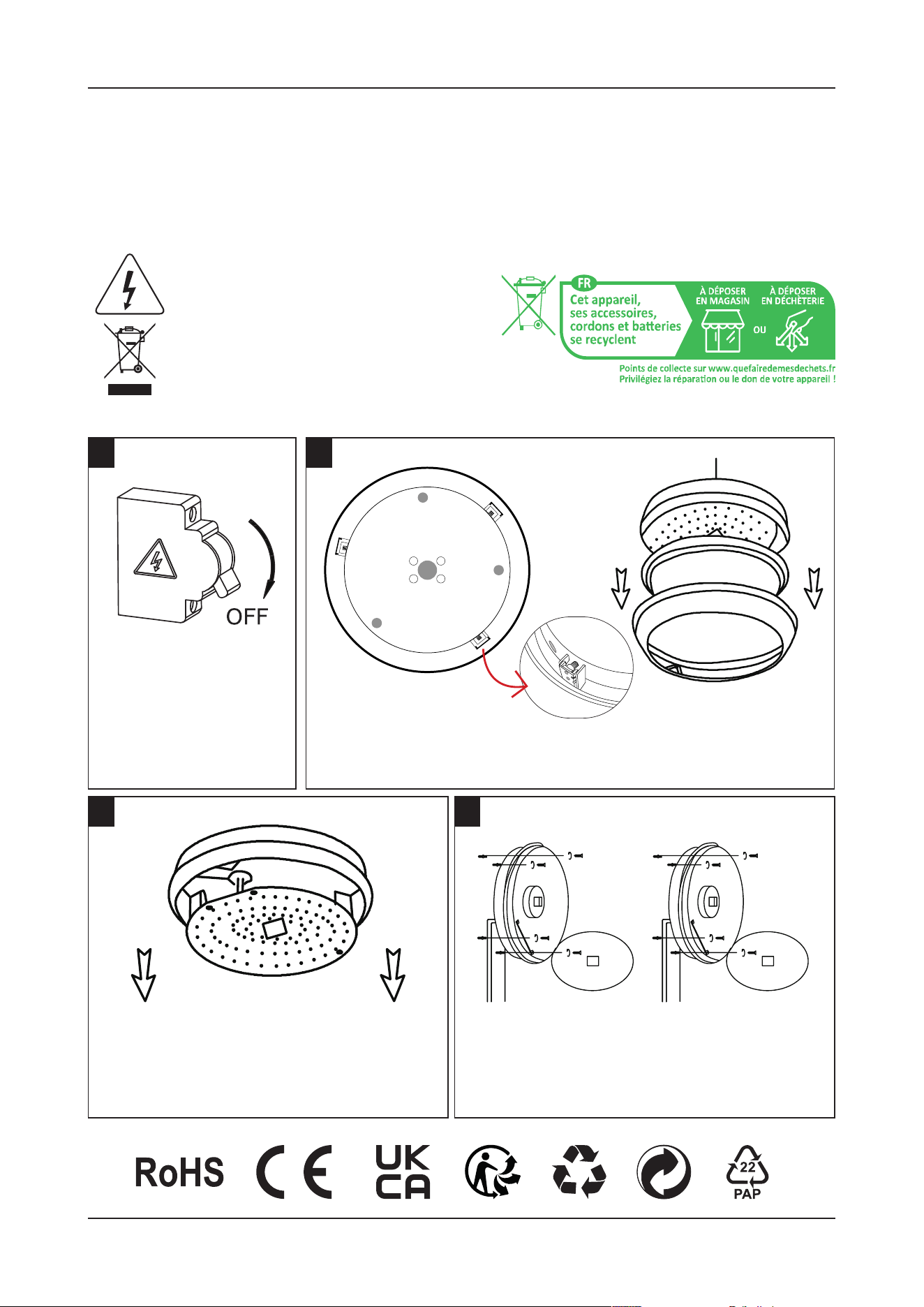
INSTALLATION INSTRUCTIONS
1
3 4
2
Switch OFF the power
before starting the
installation.
Carefully press and unlock the screw
on the led hinged tray and hold the
tray at an upward 90Degree position.
Hold the product upside down.
Hold the product in place, mark & drill the holes
into the wall and nail the alligator into the hole.
Feed the supply cable into the luminaire through
the cable entry hole
Remove the cover by holding the luminaire upside down. Press 3
clips on the sides and pull the base upwards to open and set aside.
• Please make sure to turn o the power before starting the installation.
• Installation must be performed by a qualified person.
• The light source of this luminaire is not replaceable, when the light source reaches its end of life
the whole luminaire should be replaced.
• If the external flexible cable or cord of this luminaire is damaged, it shall be exclusively replaced
by the manufacturer or his service agent or a similar qualified person in order to avoid a hazard.
WARNING
This marking indicates that this
product should not be disposed
of with other household wastes.
Caution, Risk of electric shock
INSTRUCTIONS FOR CHANGING COLOR &
POWER (AVAILABLE ON DRIVER)
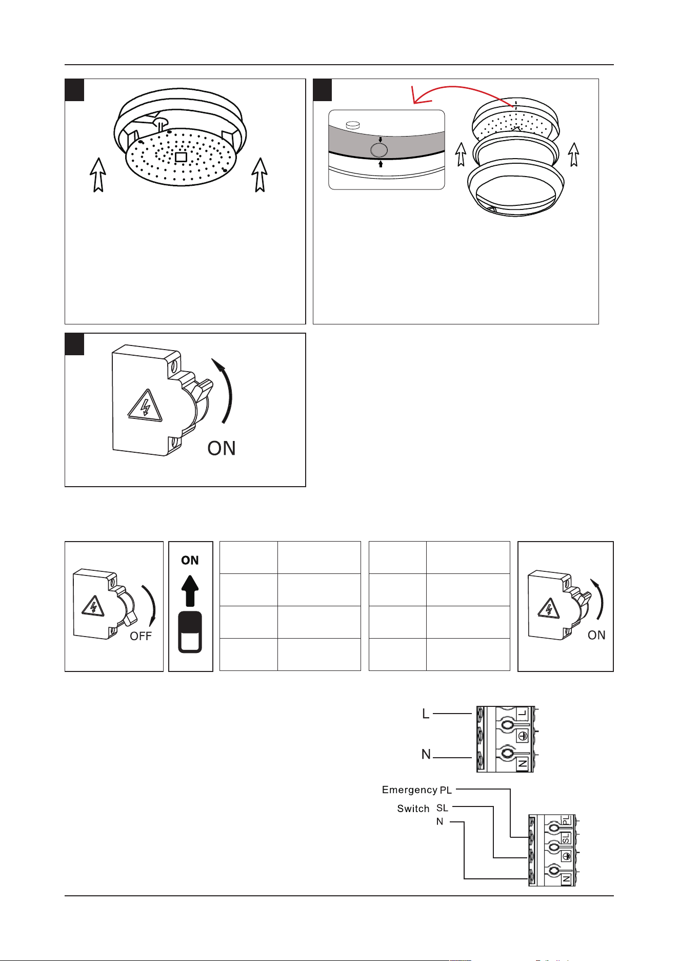
PRE-INSTALL EMERGENCY FUNCTION TEST
5
7
6
• Once the base is installed, carefully
put back the hinged tray by pushing
it forward.
• Hold the tray with the base and
twist the screw to lock it back.
• Connect the AC cable according to the diagram.
• Press the test button on the driver. The emergency
function will be activated, and the charging indi-
cation will be o.
• Disconnect the battery pack, the charging indicat-
ed LED o.
NOTE: Aer installation, allow 36 hours to ensure full
battery charge and then interrupt the supply.
Switch ON the power to test the light.
• Carefully close the cover by aligning with
the marked arrows on the base ( Locate
the Side conduit) and the cover to avoid
breakage while closing.
• Push down from all 3 sides to properly
secure the 3 clips on the sides.
CCT
ON 3000K (Y)
ON 4000K (WY)
ON 6400K (W)
POWER
ON 20W
ON 16W
ON 8W
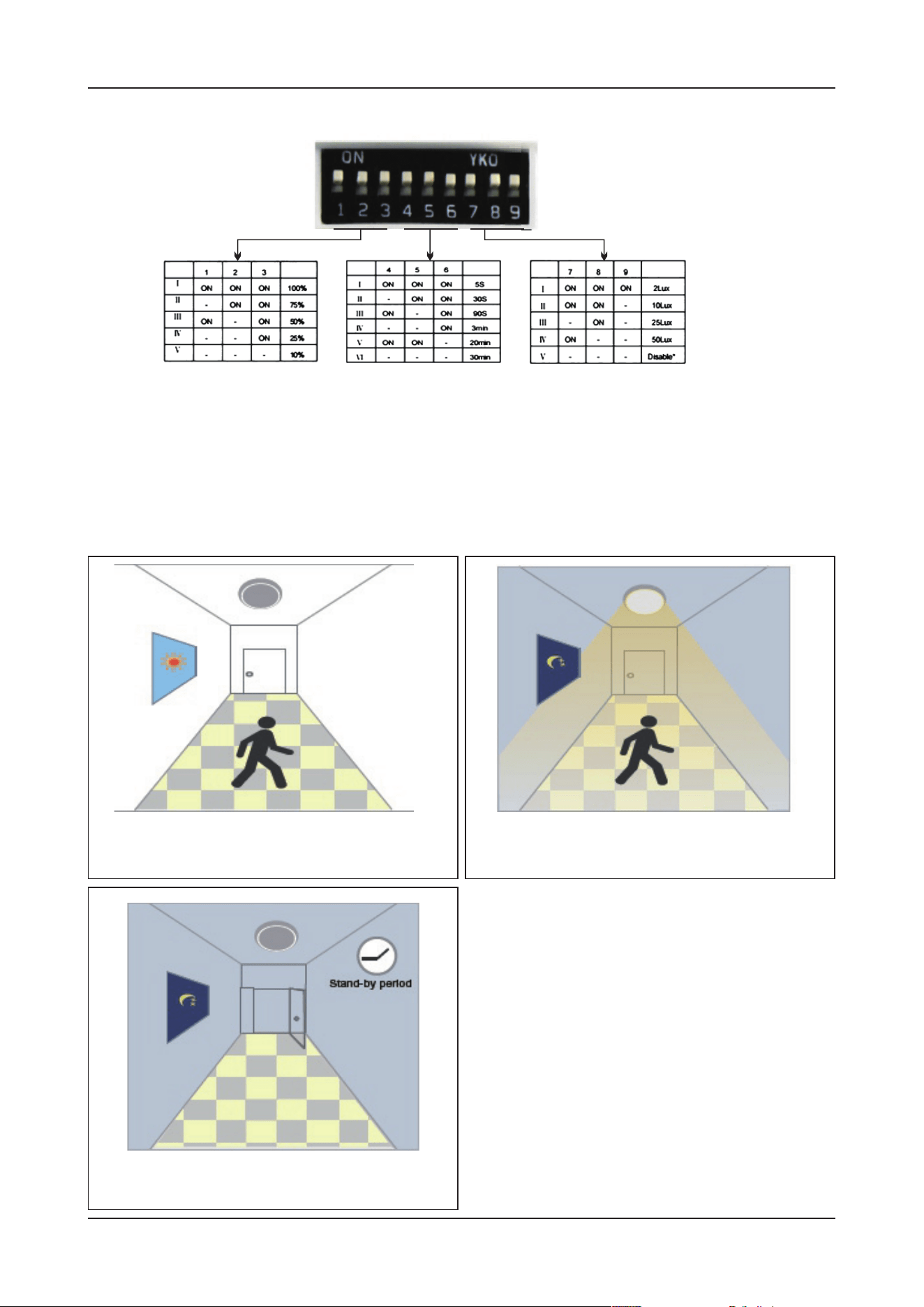
SENSOR SETTINGS
APPLICATION
[FUNCTION DEMO - DIMMABLE CONTROL/CORRIDOR FUNCTION]
FIG 1 FIG 2 FIG 3
• Detection Area - It can be adjusted by combining DIP switches for specific application [FIG 1].
• Hold Time - Time period during which the light will be ON aer the last detection [FIG 2].
• Daylight Threshold - Daylight sensor priors motion sensor. Set Threshold for Specific needs. If
disabled, only motion sensor will work [FIG 3].
When motion is detected, but the daylight is
sucient, the light will remain OFF.
Aer a stand-by period, the light will
switch OFF.
When motion is detected, and the daylight
is insucient, the light will be ON.