
VIVOTEK - Built with Reliability
2 - User's Manual
Table of Contents
Chapter One Hardware Installation and Initial Conguration ...................................................................................... 7
Introducing the Network Video Recorder ............................................................................................................... 7
Special Features ............................................................................................................................................. 8
Safety .............................................................................................................................................................. 8
Chassis Dimensions .................................................................................................................................... 9
Physical Description ........................................................................................................................................... 10
Topology ............................................................................................................................................................... 11
Hardware Installation .......................................................................................................................................... 12
Interface Connections ......................................................................................................................................... 13
Initial Conguration - via a Local Console ............................................................................................................ 14
Initial Conguration - via a Web Console (Optional) ............................................................................................ 17
LED Indicators ...................................................................................................................................................... 19
Power Up and Power Down ................................................................................................................................. 20
Section One Management over a Local Console ...................................................................................................... 21
Chapter Two Introduction to the Local Console Interface .......................................................................................... 21
2-1. How to Begin ................................................................................................................................................. 23
2-2. Operation on a Camera View Cell ................................................................................................................. 27
2-2-1. PTZ Panel ........................................................................................................................................... 27
2-2-2. Digital Zoom Panel ............................................................................................................................. 31
2-2-3. Others ................................................................................................................................................. 32
2-2-4. Right-click Commands ........................................................................................................................ 33
Chapter Three Conguation Using the Local Console .............................................................................................. 34
The Main Control Portal ....................................................................................................................................... 34
3-1. Layout .................................................................................................................................................... 34
3-2. Settings .................................................................................................................................................. 35
3-2-1. Settings - Overview ...................................................................................................................... 35
3-2-2. Settings - Camera - Management................................................................................................ 36
3-3-1. Settings–Camera–Media ............................................................................................................. 44
3-3-2. Settings - System - Information ................................................................................................... 51
3-3-2. Settings - System - Maintenance ................................................................................................. 52
3-3-3. Settings - System - Display .......................................................................................................... 53
3-4. Settings - User ................................................................................................................................ 54
3-4-1. Login / Logout .............................................................................................................................. 55
3-5. Settings - Network ........................................................................................................................... 56
Settings - Network - IP ........................................................................................................................... 56
Settings - DDNS ..................................................................................................................................... 57
Settings - Service ................................................................................................................................... 58
3-6. HTTPS certicate .................................................................................................................................. 62
3-7. User ....................................................................................................................................................... 63
Settings–User-Login / Logout................................................................................................................. 65
3-8. Information ............................................................................................................................................. 66
Section Two Management over a Web Console ....................................................................................................... 67

VIVOTEK - Built with Reliability
4 - User's Manual
Revision History
* Rev. 1.0: Initial release.
Some low quality Ethernet cables with smaller core diameter can seriously reduce the
transmission rate. Use CAT5e or CAT6 cables with a wire gauge of 24AWG for Receiver’s uplink
port. A thicker core 24 AWG network cable can oer less resistance than a 26 AWG or 28 AWG
network cable.
Use shielded cables in high noise environments where cross talk and EMI can occur.
IMPORTANT:
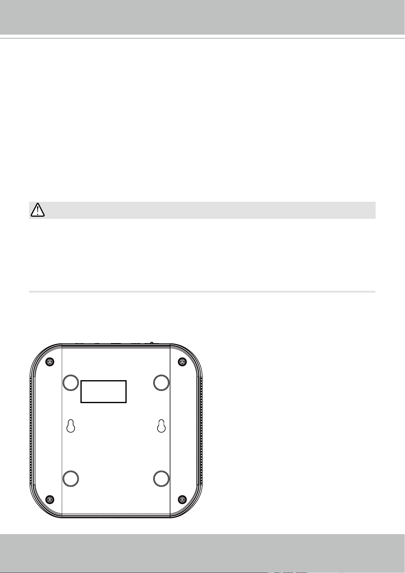
The product name tag and MAC address is here.
VIVOTEK - Built with Reliability
User's Manual - 5
Technology License Notice
Notices from HEVC Advance:
THIS PRODUCT IS SOLD WITH A LIMITED LICENSE AND IS AUTHORIZED TO BE USED ONLY
IN CONNECTION WITH HEVC CONTENT THAT MEETS EACH OF THE THREE FOLLOWING
QUALIFICATIONS: (1) HEVC CONTENT ONLY FOR PERSONAL USE; (2) HEVC CONTENT THAT
IS NOT OFFERED FOR SALE; AND (3) HEVC CONTENT THAT IS CREATED BY THE OWNER OF
THE PRODUCT. THIS PRODUCT MAY NOT BE USED IN CONNECTION WITH HEVC ENCODED
CONTENT CREATED BY A THIRD PARTY, WHICH THE USER HAS ORDERED OR PURCHASED
FROM A THIRD PARTY, UNLESS THE USER IS SEPARATELY GRANTED RIGHTS TO USE THE
PRODUCT WITH SUCH CONTENT BY A LICENSED SELLER OF THE CONTENT. YOUR USE OF
THIS PRODUCT IN CONNECTION WITH HEVC ENCODED CONTENT IS DEEMED ACCEPTANCE OF
THE LIMITED AUTHORITY TO USE AS NOTED ABOVE.
H.264
THIS PRODUCT IS LICENSED UNDER THE AVC PATENT PORTFOLIO LICENSE FOR THE
PERSONAL AND NON-COMMERCIAL USE OF A CONSUMER TO (i) ENCODE VIDEO IN
COMPLIANCE WITH THE AVC STANDARD ("AVC VIDEO") AND/OR (ii) DECODE AVC VIDEO
THAT WAS ENCODED BY A CONSUMER ENGAGED IN A PERSONAL AND NON-COMMERCIAL
ACTIVITY AND/OR WAS OBTAINED FROM A VIDEO PROVIDER LICENSED TO PROVIDE AVC
VIDEO. NO LICENSE IS GRANTED OR SHALL BE IMPLIED FOR ANY OTHER USE. ADDITIONAL
INFORMATION MAY BE OBTAINED FROM MPEG LA, L.L.C. SEE HTTP://WWW.MPEGLA.COM
VIVOTEK - Built with Reliability
6 - User's Manual
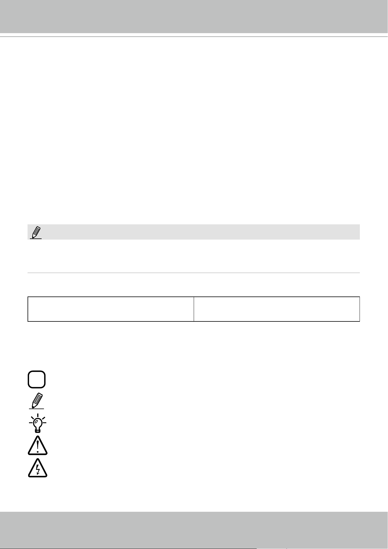
Symbols and Statements in this Document
i
INFORMATION: provides important messages or advices that might help prevent inconvenient
or problem situations.
NOTE: Notices provide guidance or advices that are related to the functional integrity of the
machine.
Tips: Tips are useful information that helps enhance or facilitate an installation, function, or
process.
WARNING! or IMPORTANT: These statements indicate situations that can be dangerous or
hazardous to the machine or you.
Electrical Hazard: This statement appears when high voltage electrical hazards might occur
to an operator.
Read Before Use
The use of surveillance devices may be prohibited by law in your country. The Network Video
Receiver is not only a high-performance web-ready camera but can also be part of a flexible
surveillance system. It is the user’s responsibility to ensure that the operation of such devices is
legal before installing this unit for its intended use.
It is important to first verify that all contents received are complete according to the Package
Contents listed below. Take note of the warnings in the Quick Installation Guide before the
Network Video Receiver is installed; then carefully read and follow the instructions in the
Installation chapter to avoid damage due to faulty assembly and installation. This also ensures
the product is used properly as intended.
The Network Video Receiver is a network device and its use should be straightforward for those
who have basic networking knowledge. It is designed for various applications including video
sharing, general security/surveillance, etc. The Configuration chapter suggests ways to best
utilize the Network Video Receiver and ensure proper operations. For creative and professional
developers, the URL Commands of the Network Video Receiver section serves as a helpful
reference to customizing existing homepages or integrating with the current web server.
Package Contents
■ RX9502
■ Power adapter
■ Mouse
■ Quick Installation Guide
The operating system and management software are installed on a ash memory mounted
on the main board. Except for the plug-ins for the onscreen control, there is no need to install
software.
NOTE:

VIVOTEK - Built with Reliability
User's Manual - 7
Chapter One Hardware Installation and
Initial Conguration
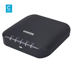
Introducing the Network Video Recorder
VIVOTEK’s RX9502 is an H.265 Single-Channel Ultra-HD Video Receiver. Delivering high-
quality and detailed images, it is equipped for up to 32-CH network cameras and a maximum
network camera resolution of 8-Megapixels. The machine can drive an HD monitor directly via
HDMI, and supports decode options of 4K 30 fps, four H.265 1080p 120 fps, nine H.265 720p
270 fps, or sixteen H.265 D1 480 fps. The machine offers a more cost-effective and PC alterna-
tive solution with no costly VMS client fee, no HDD noise and no failure issues. It is suitable for
standalone viewers through local viewing. Secured and simplified IT management reduce the
requirement for end user training, further reducing long-term costs.
Space-saving, Flexible Installation
Compact size with fanless design for any small scale video surveillance installation, the model
is perfect for a single display application that requires space-saving solutions. For more fexible
installation, it supports, wall or desktop mount options.
Various Split-window Layout & Fisheye Dewarp Support
The machine provides various split modes for layout display (1x1, 2x2, 3x3, 1P+3, 2P+3, 1M+5,
1P+6, 3V, 1M+12, 1M+31, 4x4) and supports VIVOTEK’s fisheye camera Fisheye Dewarp func-
tion, which provides multiple de-warping modes to ensure the correct angle of video view and
detailed information for fexible usage.

VIVOTEK - Built with Reliability
8 - User's Manual
Safety
Connect the system to an earthed main power outlet.
Never open the housing of the power supply unit.
Install and operate the system only in a dry, weather-proof location.
Observe the following safety factors:
•
Is there visible damage to the system or power cord?
•
Is the system operating correctly?
•
Has the system been exposed to rain or moisture?
•
Has the system been in a long storage under harsh conditions or exposed to
unconforming stress?
The relevant electrical engineering regulations must be complied with at all times during the
installation.
Ensure that all maintenance and repair work is handled by qualified personnel such as
electrical engineers or network specialists.
Read this manual before installing or operating the system. The documentation contains
important safety instructions about permitted uses.
The rated AC input is: 100-240V~ 1A, 60-50Hz; the max. consumption: 11W (DC12V, 0.9A)
If a fault occurs, disconnect the power cord from the power supply.
Do not install the system close to heaters or other heat sources. Avoid locations with direct
sunlight.
All ventilation openings must not be blocked.
Use only the cables shipped with system or use appropriate cables that can withstand elec-
tromagnetic interference.
Special Features
● Runs on embedded Linux ● Fisheye Dewarp
● 1 x HDMI for local display up to 4K resolution ● Supports cameras of up to 20MP resolution
● Up to 32 Channel IP Camera Input ● ONVIF Compliance (Project Support Func-
tion)
● 1 x Gigabit RJ45 uplink Ethernet port; ● Supports Various Split-window Layout Dis-
play Modes
● 2 x USB Port (1 in Front / 1 USB 3.0 in Back) ● Snapshot / Export Media
● Size: 198 mm (W) x 200 mm (D) x 47 mm (H) ● PiP Video Control
● One Button Auto Setup ● Configuration Backup / Restore
● Compatible with VIVOTEK VSS Central Management Software*
VIVOTEK - Built with Reliability
User's Manual - 9
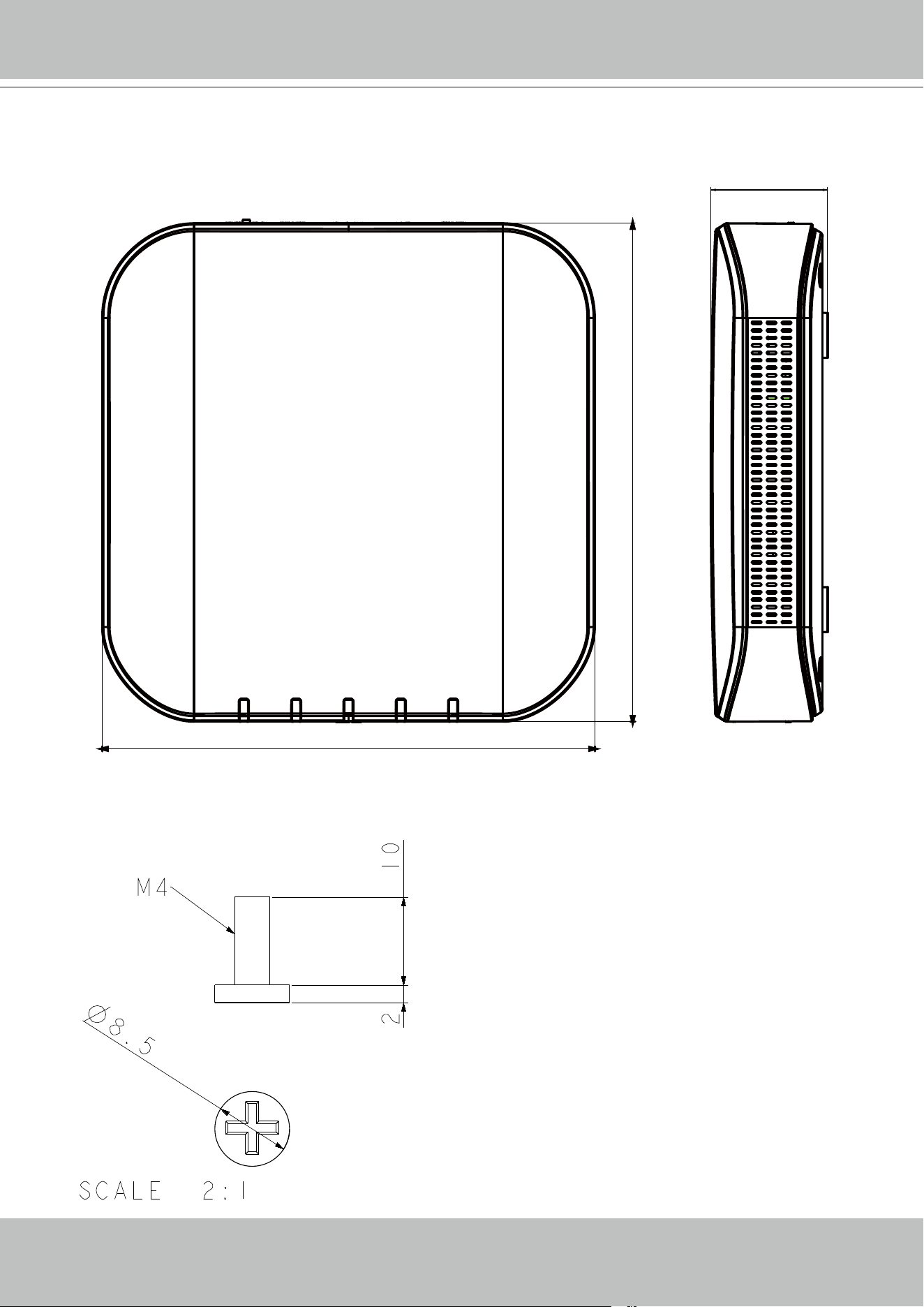
Chassis Dimensions
198
200
47
M4x10 for wall-mounting
VIVOTEK - Built with Reliability
User's Manual - 11
IMPORTANT:
It is important to leave a clearance of 10cm around the chassis. The clearance is required to
ensure an adequate airow through the chassis to ventilate heat.
2
To ensure normal operation, maintain ambient airow. Do not block the airow around chassis
such as placing the system in a closed cabinet.
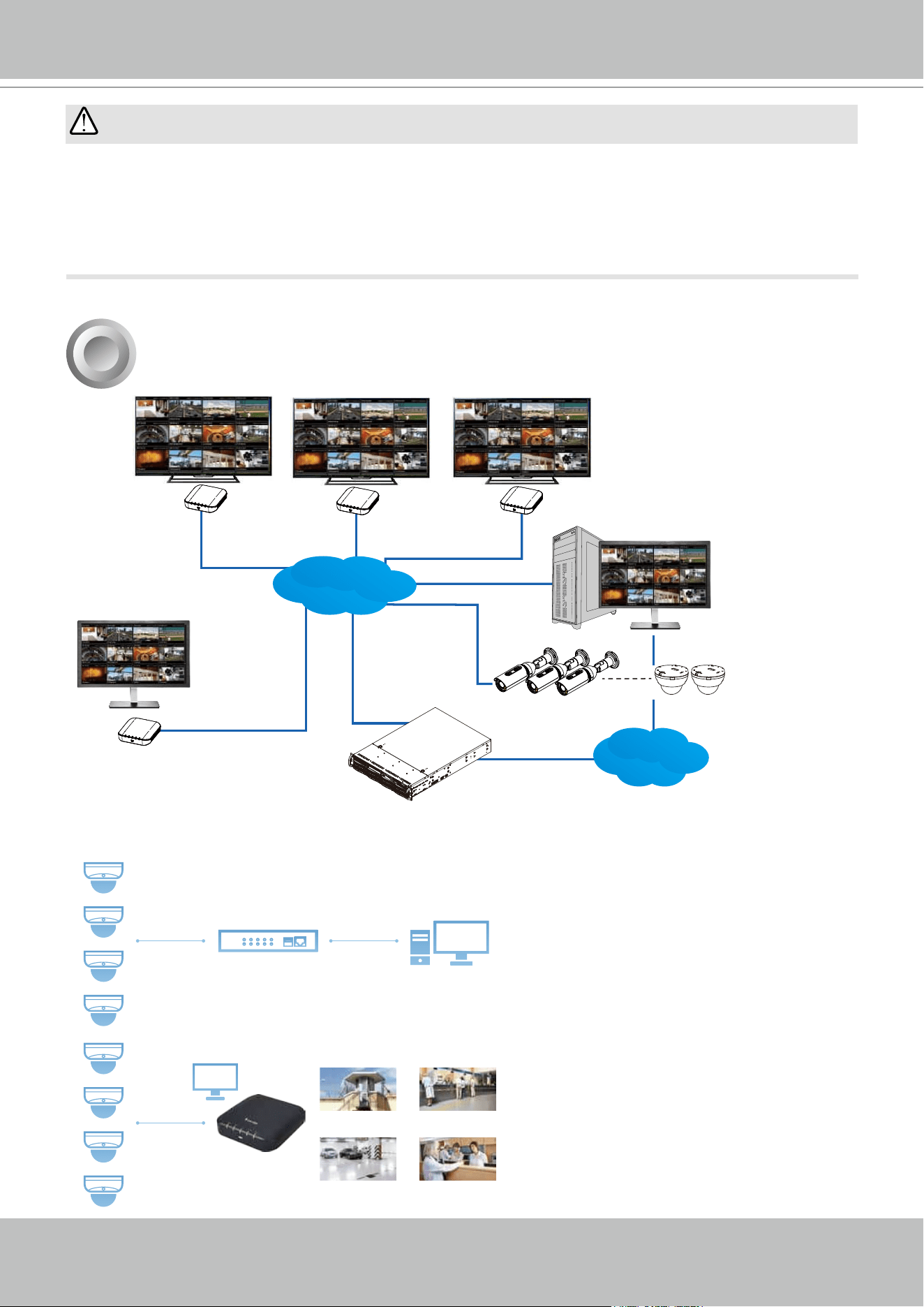
Topology
Camera 01
Camera 02
Camera 04
Camera 05
Camera 07
Camera 08
Camera 09
Camera 06
Camera 09
LAN/WAN
Surveillance center
TV wall
CMS
station
IP cameras
NVR
Remote site
Camera 01
Camera 02
Camera 04
Camera 05
Camera 07
Camera 08
LAN
NVR
Server Center Control Center
VSS
Guard Station
Sub Center
Parking Station
RX9502
Banking
Public Area
Hospital
Management
Live Monitoring
VIVOTEK - Built with Reliability
12 - User's Manual
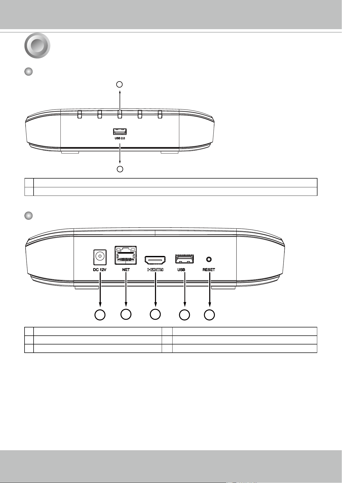
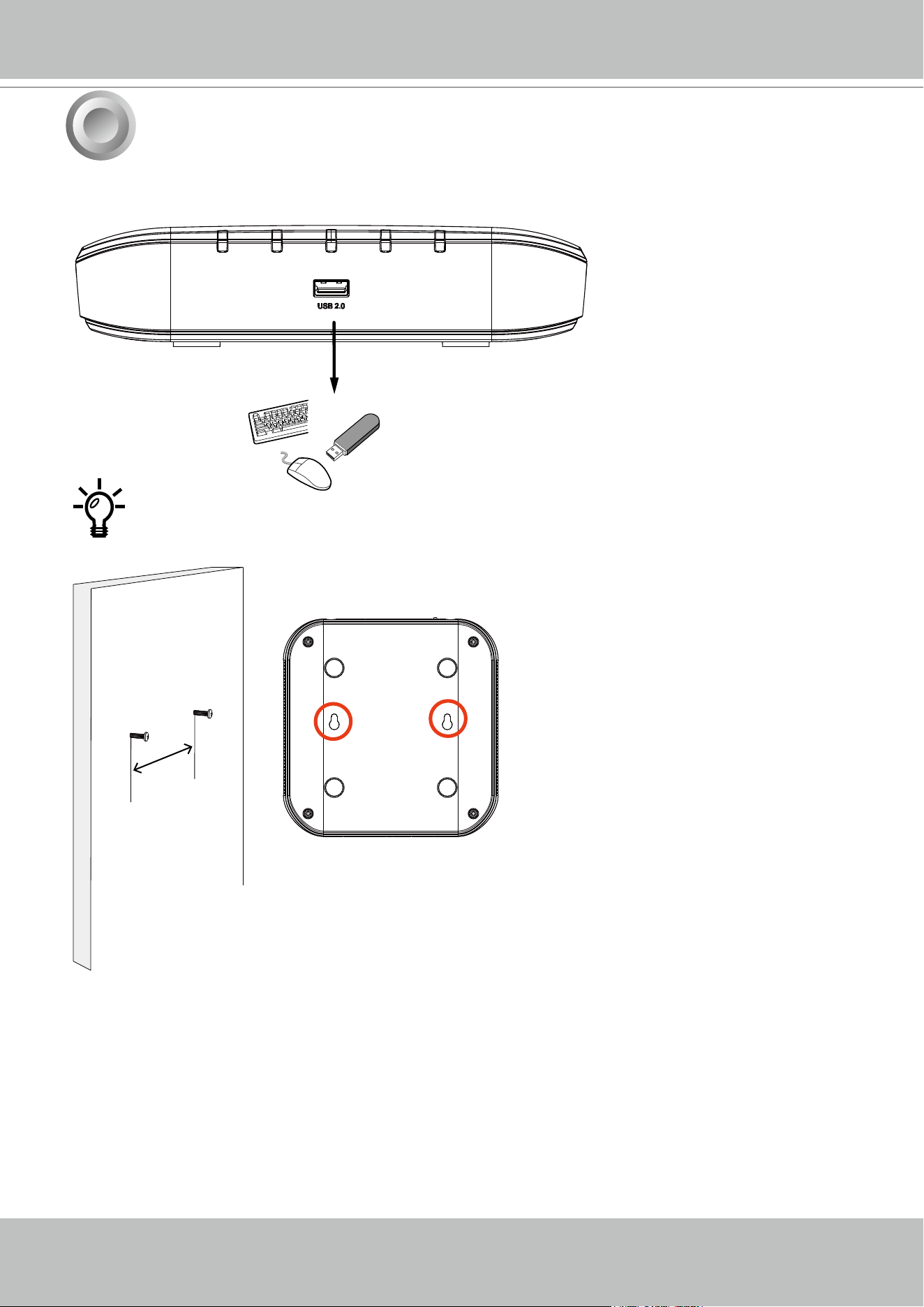
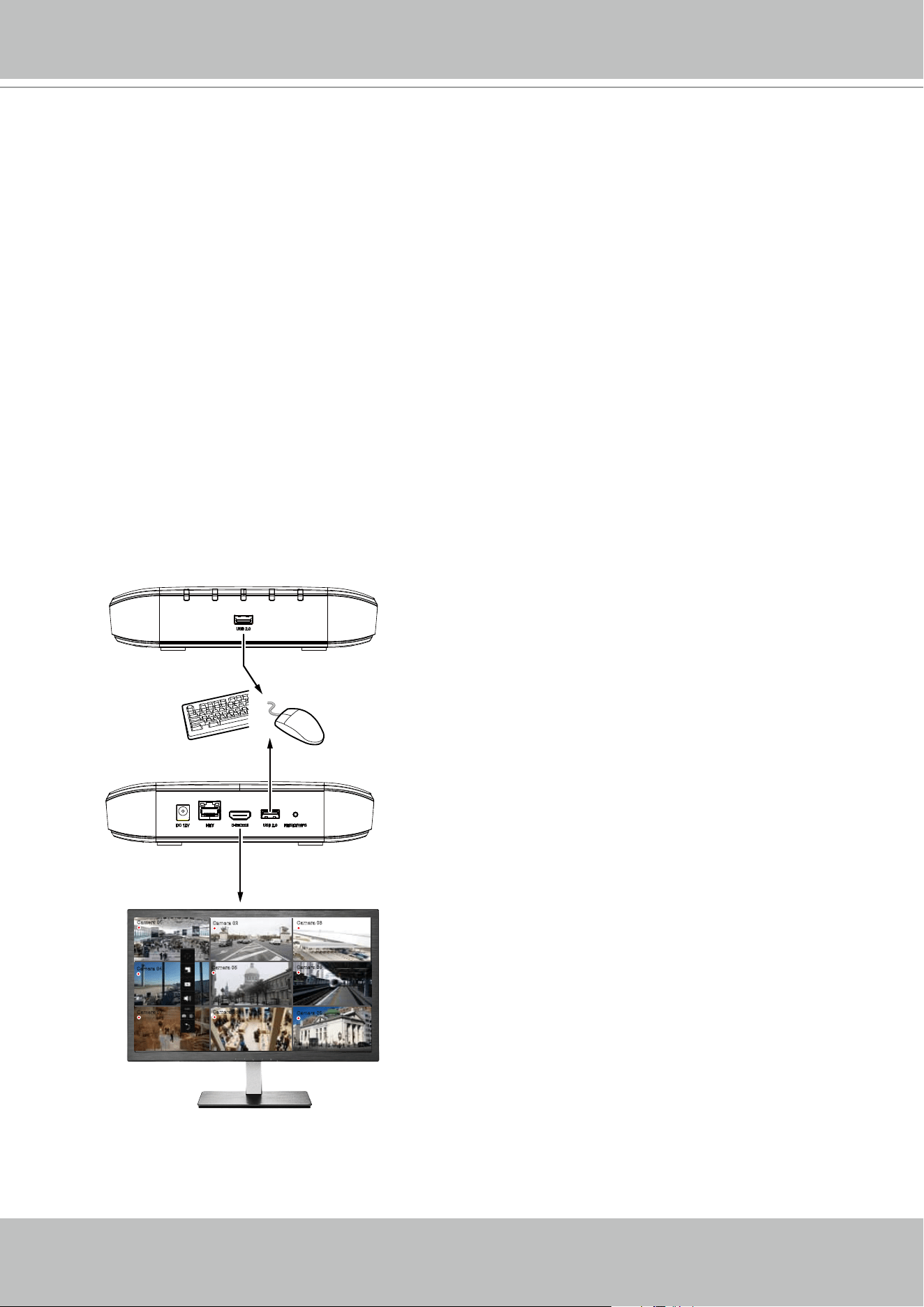
1. Connect a mouse and/or keyboard to the USB connectors at the front or the rear of the re-
ceiver.
104mm
If you prefer to hang the Receiver on wall, drill and install two screws 104mm apart.
3
Hardware Installation
VIVOTEK - Built with Reliability
User's Manual - 13
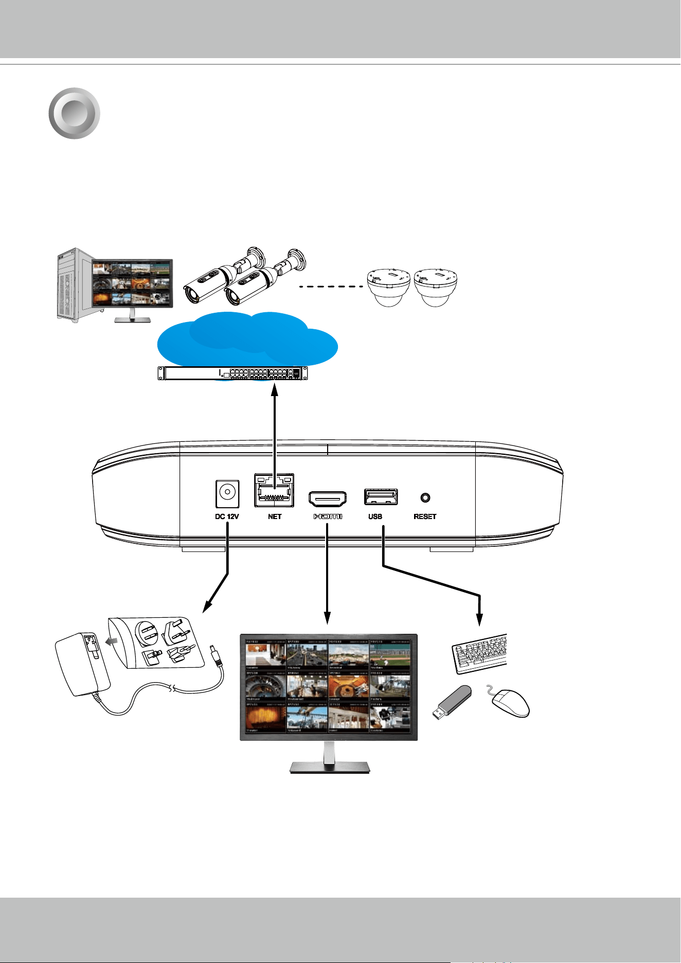
1. Connect to a monitor using an HDMI cable.
2. Connect CAT5e or better-quality Ethernet cable to the network.
3. Connect USB devices such as mouse, keyboard, or USB thumb drive (formatted in FAT for-
mat), or UPS.
4. Connect the power adaptor to the power mains and the system.
4
Interface Connections
Pressing the Reset button for longer than 10 seconds will restore the factory detaults.
AC100~240V
50/60Hz, 0.9A
LAN/WAN
USB 3.0
Camera 01
Camera 02
Camera 04
Camera 06
Camera 05
Camera 07
Camera 08
Camera 09
Camera 01
Camera 02
Camera 04
Camera 05
Camera 07
Camera 08
3.0
VIVOTEK - Built with Reliability
14 - User's Manual
5
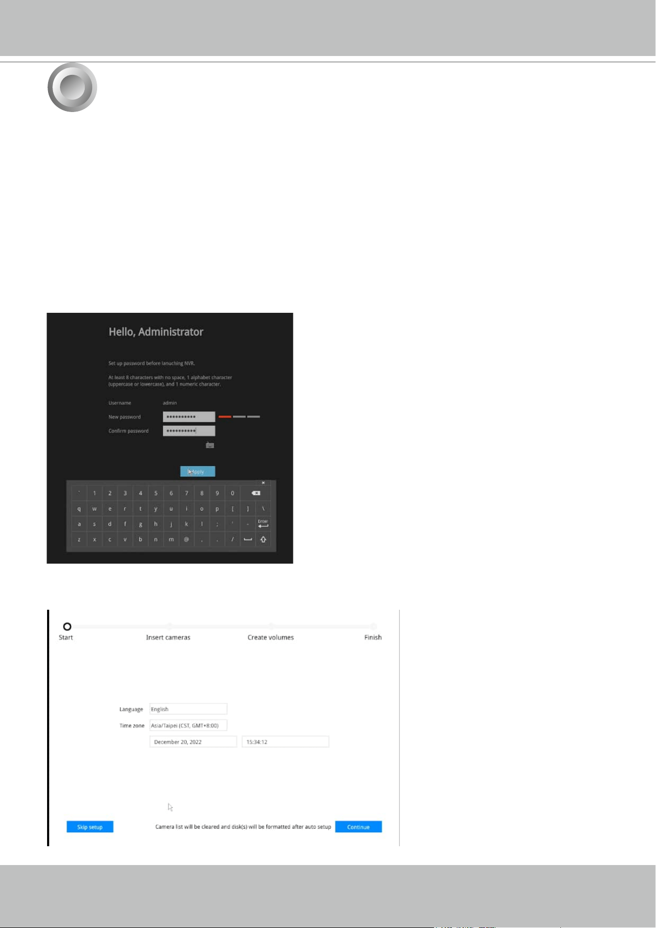
2. Select the UI language, Time zone, and current date and time. Click on the Continue button
to proceed.
A local console requires the following:
1. A monitor or TV is connected via an HDMI cable.
2. A mouse and/or a keyboard are connected to the system.
3. It is presumed that the system has not been congured yet. The Installation wizard only
appears for an uncongured machine or one that was restored to its default.
Follow the onscreen messages to complete the initial conguration:
1. When started for the rst time, the system will prompt for the forceful conguration of a
password. This ensures security from malicious network attack.
The applicable alpha-numeric characters are [0-9][a-z][A-Z][!][$][%][-][.][@][^][_][~], with a
max. length of 64 characters.
Click the Apply button when the new password is
accepted.
Initial Conguration - via a Local Console
VIVOTEK - Built with Reliability
User's Manual - 15
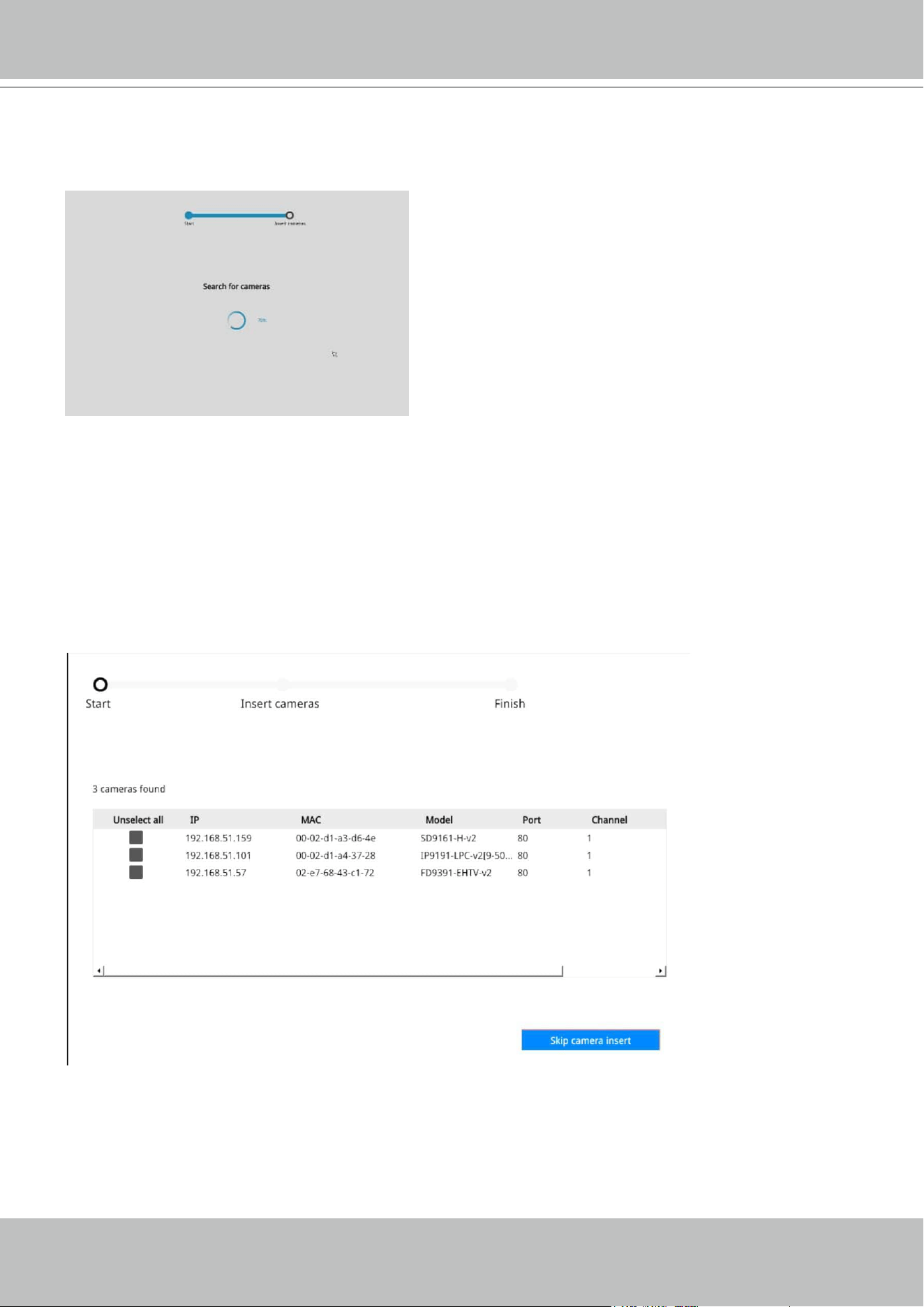
3. The system will then start to scan the local subnet for connected cameras.
4. All cameras detected on the network will be automatically listed. If necessary, deselect the
cameras you want to exclude from the conguration.
Cameras properly installed in the same subnet should all be listed. If you cannot nd a
camera, examine its network connections or network conguration.
VIVOTEK - Built with Reliability
16 - User's Manual
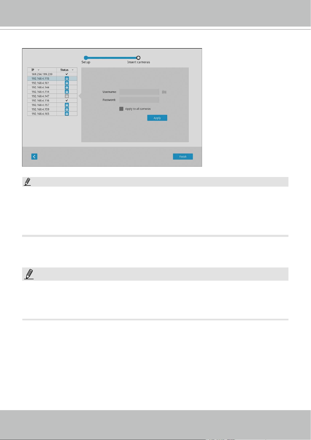
Although the system supports MAC Binding, the system should be able to detect VIVOTEK's
cameras within the network regardless of the presence of a DHCP server. Ideally, cameras
and the Receiver should reside in the same subnet. If a camera's IP is changed for some
reasons, the system should be able to detect its new IP.
NOTE:
1. The resolution and fps (frame rate per second) of stream 1 may vary depending on the
specications of dierent cameras.
2. Up to two clients viewing 2x 720P streams is acceptable. If more clients are simultaneously
viewing more video streams, the machine can be stressed.
NOTE:
Enter the credentials for each selected cameras on screen. Click Finish to proceed.
VIVOTEK - Built with Reliability
User's Manual - 17
6
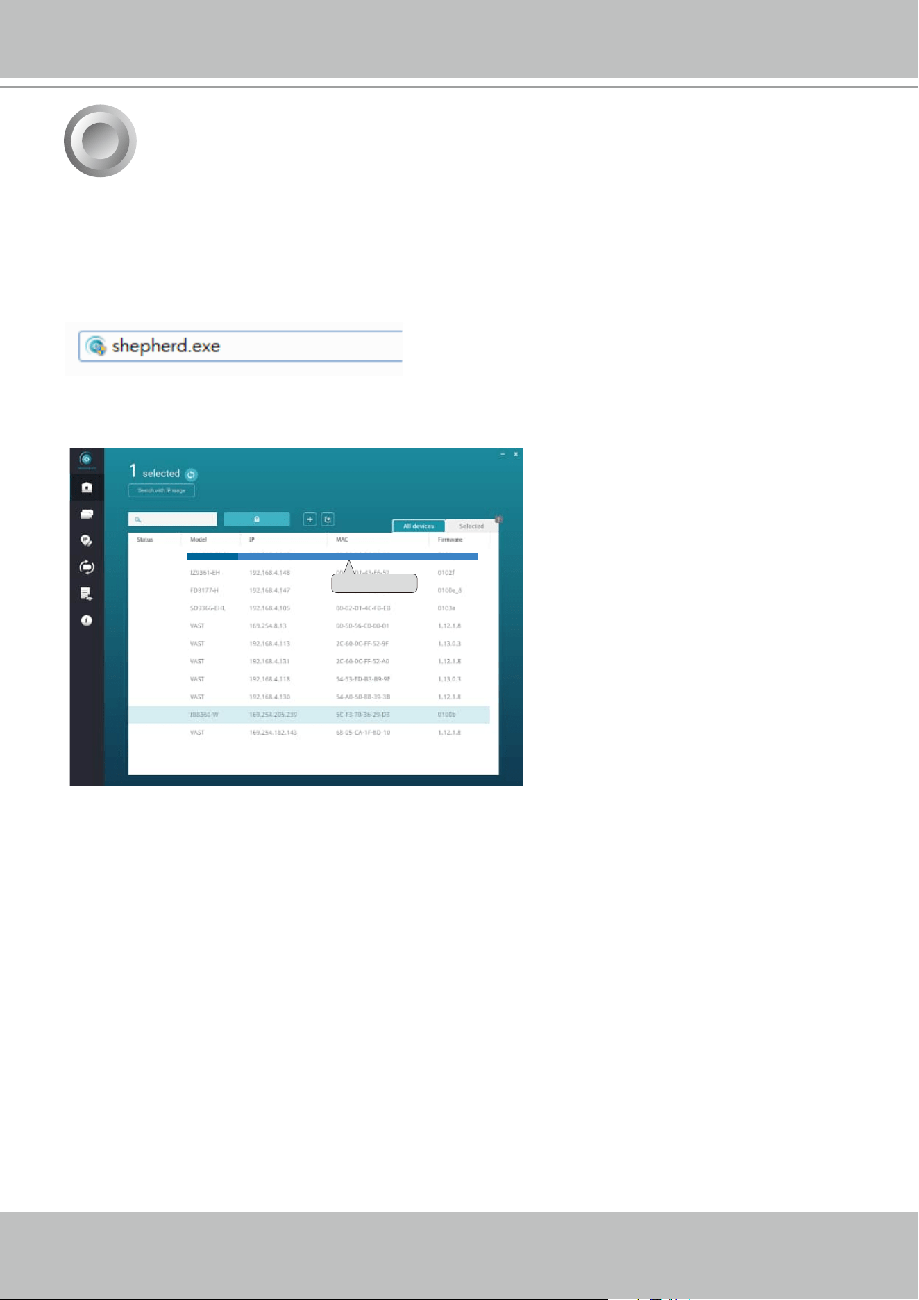
2. From a management computer, download and execute the Shepherd utility software. Follow
the onscreen instructions to complete the installation.
1. Connec the power cord to start the Receiver. Wait for the system status LED to light green.
3. Start the Shepherd utility. The Shepherd utility will discover the Receiver located in the same
subnet.
0002D1730202
IB8360-W 192.168.4.151 00-02-D1-73-02-02
RX9502
Initial Conguration - via a Web Console (Optional)
4. Double-click on the RX9502 entry to start a web session with the Receiver system.
VIVOTEK - Built with Reliability
18 - User's Manual
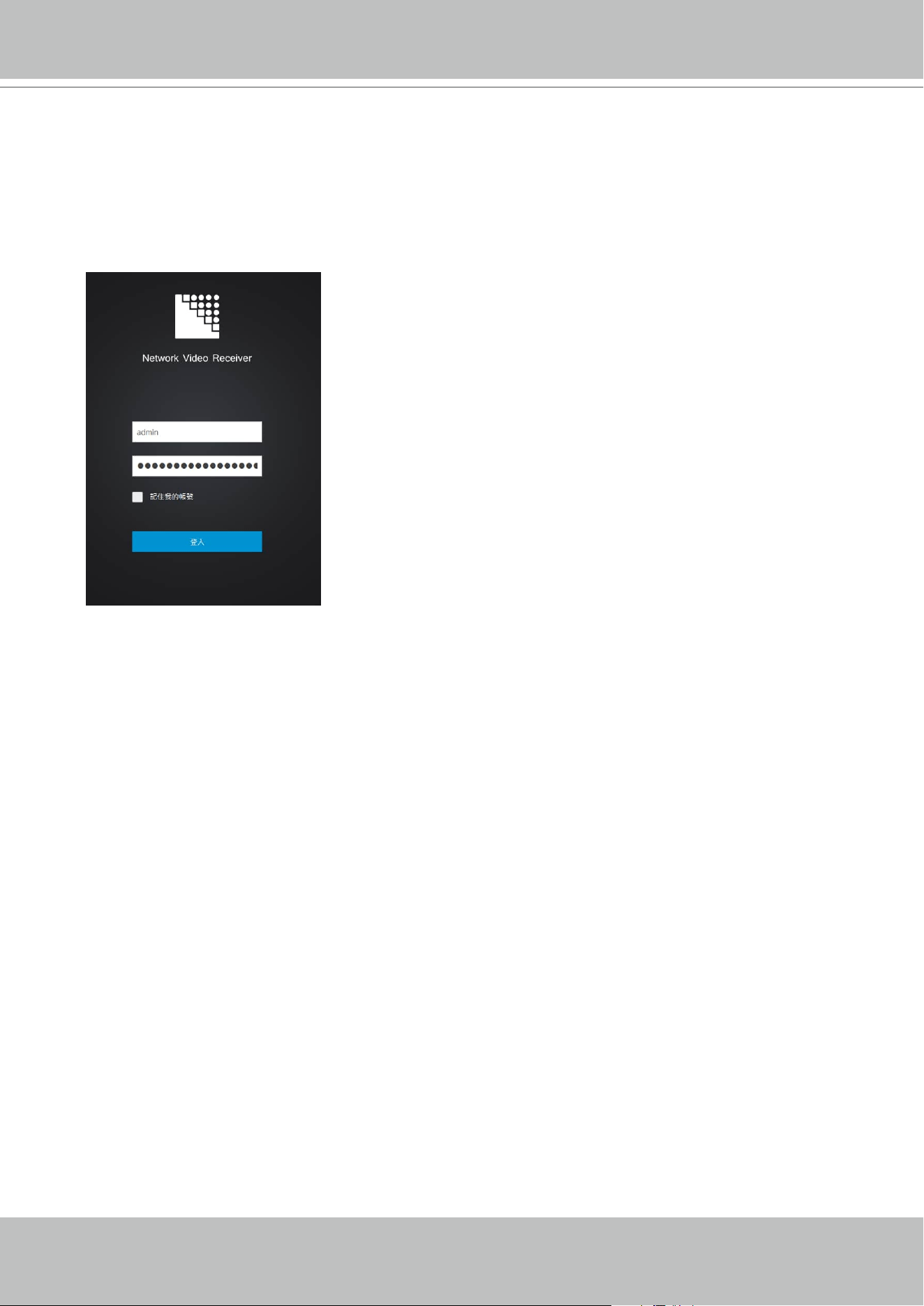
5. If you have congured a user name and password on the local console, use them to log in.
Ideally, the initial conguration is performed via the local console. Expand the menu on the
right of the Login button. Select and click on the Settings button to begin your conguration.
6. Refer to the later discussions for the rest of the conguration procedure.
If accessed for the rst time and no password has been congured, enter admin and admin
as user name and password.
VIVOTEK - Built with Reliability
User's Manual - 19
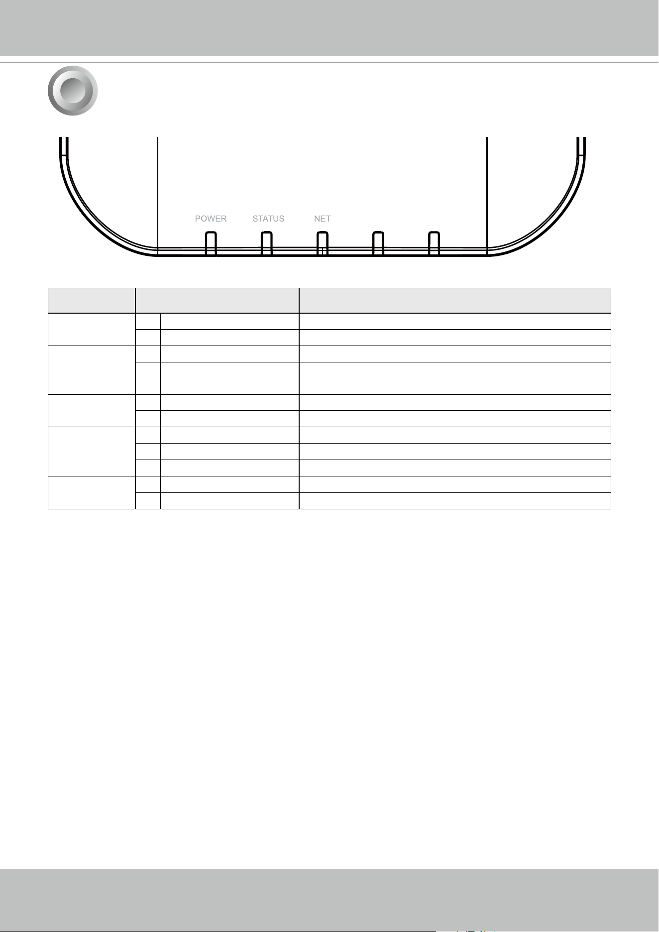
LED Indicators
7
CAMERA RESET
Name Behavior Denitions
1. Power
1 OFF Powered down.
2 Solid
Green Device is up and running.
2. Status 1 Green solid System is ready.
2 Blinking Red every 1
second
Firmware or device pack is being updated.
3. NET 1 OFF The Ethernet port is disconnected.
2
Orange blinking Data is being transmitted and received.
4. Camera 1 Solid Green All congured cameras are online.
2 Solid
Red One or more congued cameras is disconnected.
3 OFF No camera is connected.
5. Reset 1 Blinking Blue Reset or Restore to default is taking place.
2 OFF Normal status.
VIVOTEK - Built with Reliability
20 - User's Manual
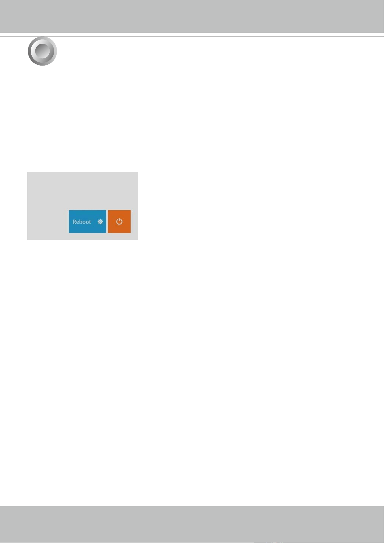
To power up and power down,
On the initial conguration:
Connect the power adapter between the system and power outlet.
After the initial connection,
Press the software power down button on the management session to power down. the system
should start ushing the cached contents in system memory and gracefully shut down.
Once powered down, you need to re-connect the power cord to start the Receiver again.
Power Up and Power Down
8
VIVOTEK - Built with Reliability
User's Manual - 21
Section One
Management over a
Local Console
Chapter Two
Introduction to the Local Console Interface
Camera 01
Camera 02
Camera 03
Camera 04
Camera 06
Camera 05
Camera 07
Camera 08
Camera 09
VIVOTEK - Built with Reliability
22 - User's Manual
By default, a live view appears on an HDMI monitor. The interface architecture of the local
console is illustrated as follows:
LiveView Main screen
Main control portals
Layout
Settings
Camera
System
Information
Maintenance
Display
User
Network
Overview (camera connection & storage)
Digital zoom
PTZ
Snapshot
Deselect camera
Config. portal
Camera portal
Information
Audio
Virtual keypad
When a view cell is selected
Management
Media
Image
PTZ settings
Customer support
Login / Logout
User
IP
DDNS
Service
HTTP certificate
Due to the limitation of system resources, the sheye dewarp (1R & 1P modes) can only take
place on one view cell, for one sheye camera.
IMPORTANT:
VIVOTEK - Built with Reliability
User's Manual - 23
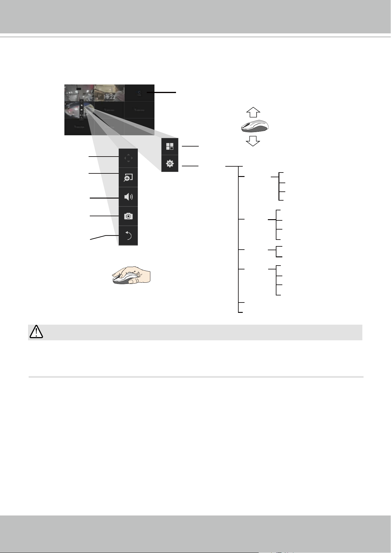
2-1. How to Begin
1. How to access the Conguration Portal?
Make sure a mouse is attached to your Receiver. Move your mouse cursor, and the
Conguration Portal will appear on screen. For all the congurable options available through
this portal, please refer to Chapter 3 on page 34.
2. How to access the Camera Portal?
Single click to select a view cell, the Camera Portal will appear. The system automatically
detects the characteristics of an individual camera when you select a view cell.
This portal appears with a camera that supports mechanical PTZ.
This portal appears with a camera that does not support mechanical PTZ.
You can also hide these portal toolbar. Right-click on the LiveView screen to
display the option.
Here are some operation steps using the tool bar:
1. Single-click to select a view cell and bring out the tool bar.
2. Double-click to expand a view cell to the full view.
3. Double-click again to shrink the view cell to the original size.
Tips:
VIVOTEK - Built with Reliability
24 - User's Manual
PTZ control panel for ordinary
PTZ type
PTZ control panel for joystick type PTZ
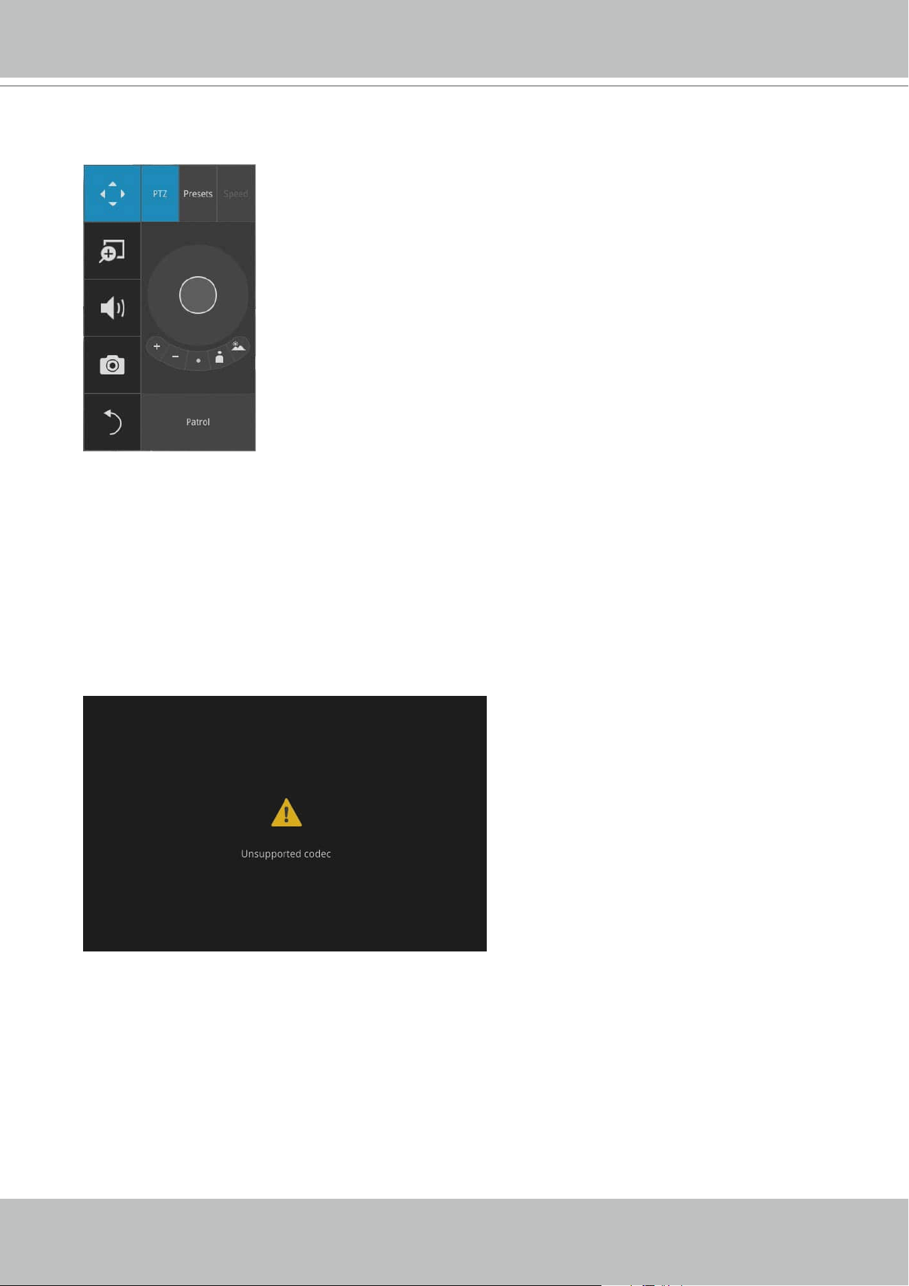
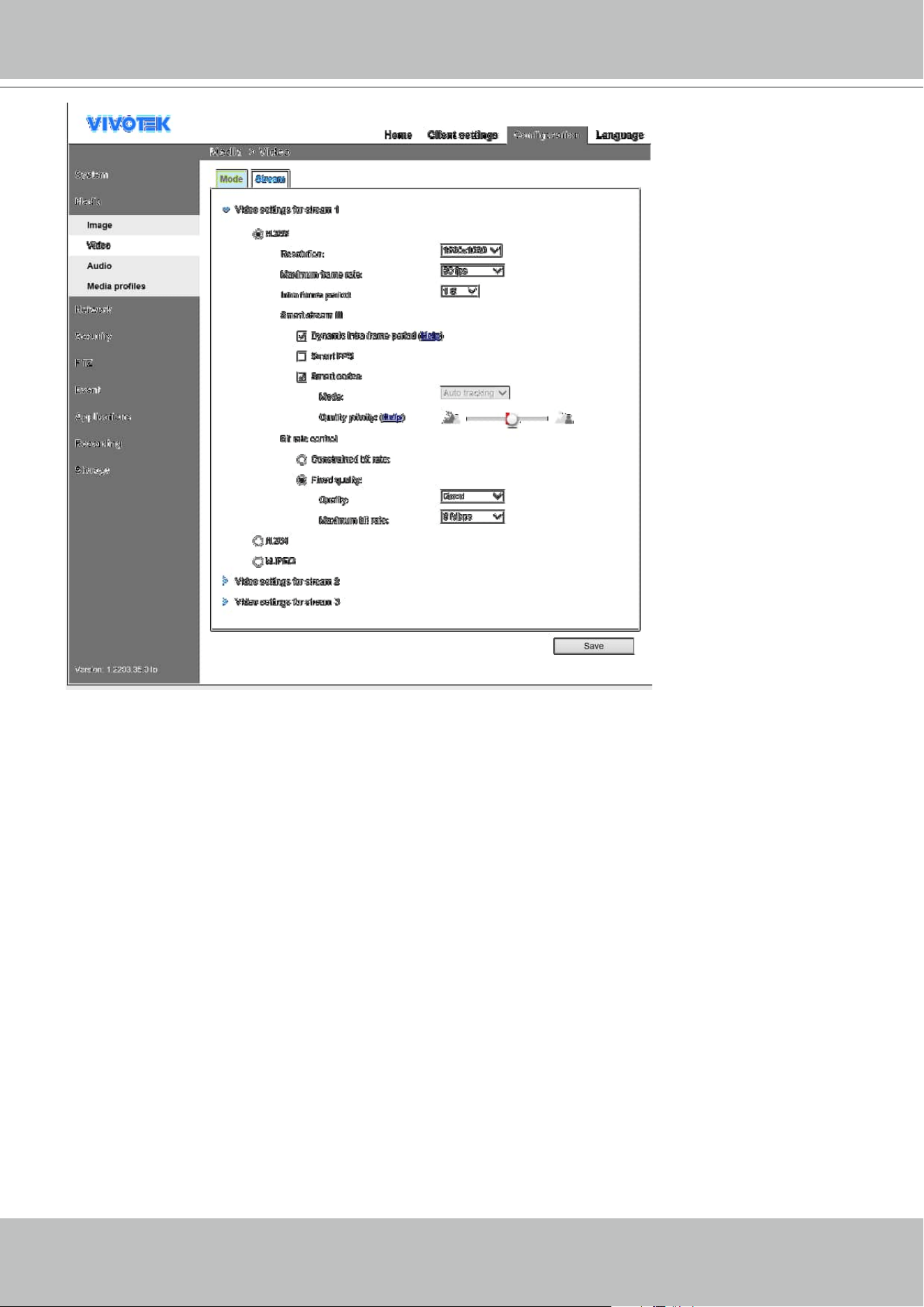
5. Why live view is unavailable?
The default live view receives a camera's stream #2. If a camera's stream #2 is congured using
MPEG-4 as the video codec, the following message will prompt.
You can use the Shepherd utility to locate the camera and open a web console with the camera.
Go to the Conguration > Media > Video window to congure the video codec of stream #2
into H.264 or H.265.
VIVOTEK - Built with Reliability
User's Manual - 25
VIVOTEK - Built with Reliability
26 - User's Manual
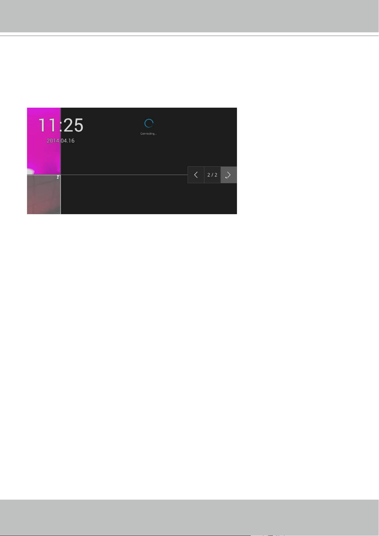
6. How do I move to another layout page?
Move your cursor to the right hand side of your screen. The page turner buttons will appear as
shown below.
For example, if you have 8 cameras placed on 2 2x2 layout pages, use these buttons to visit
dierent pages.
7. Why the onscreen tool bars disappear after some time?
The system comes with idle modes. Below are the applicable conditions:
1. Live view: if no management activities occur for 5 seconds, the tool bars disappear from
screen. When in the idle mode, mouse cursor and tool bars will disappear. Moving the mouse
cursor will re-activate the screen.
2. Settings page: If left unattended for 10 minutes, system will automatically log out. The
system will prompt for user credentials if a user tries to access the Settings page again.
VIVOTEK - Built with Reliability
User's Manual - 27
2-2. Operation on a Camera View Cell
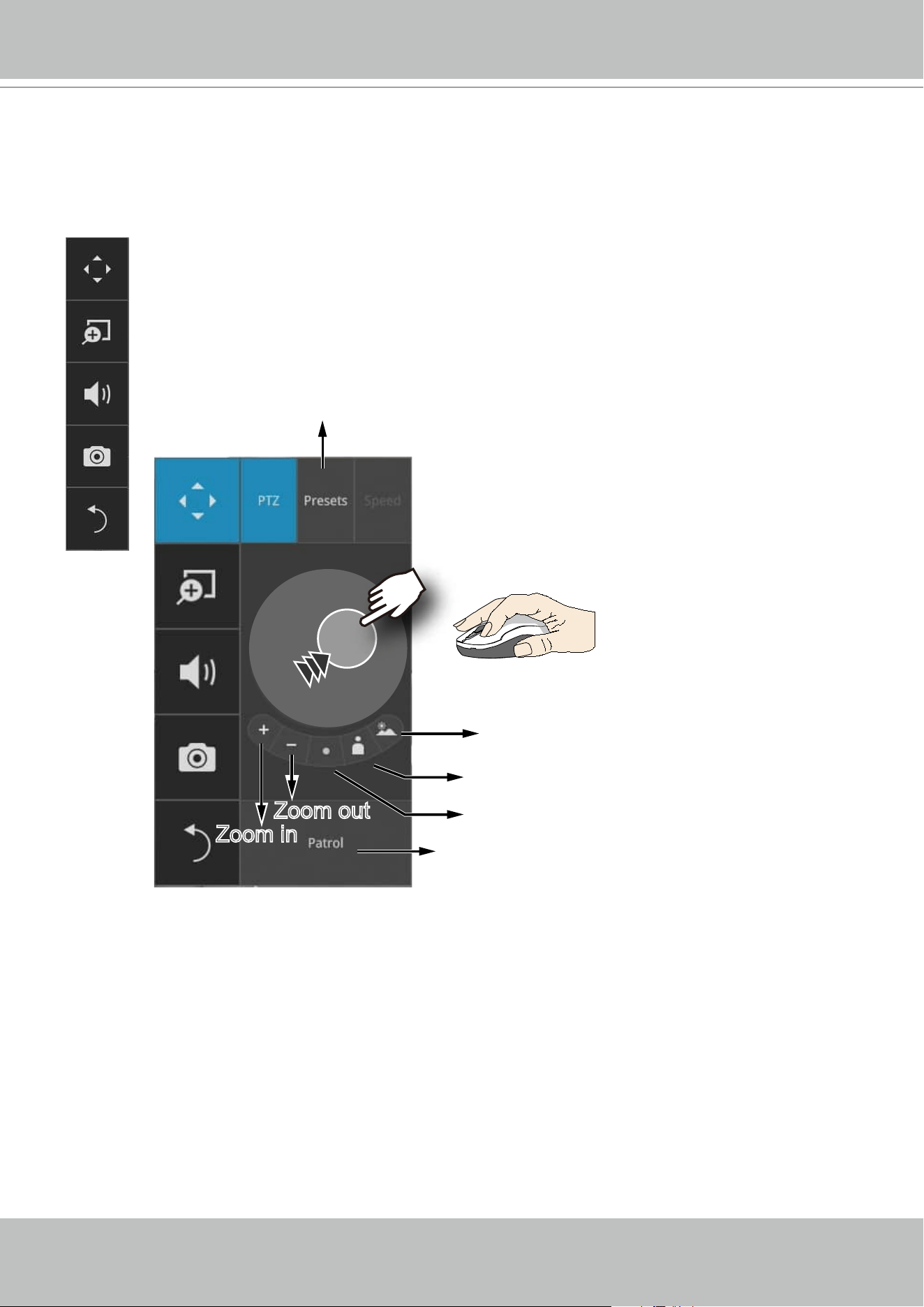
Once you selected a camera, click on the PTZ button on a camera portal.
2-2-1. PTZ Panel
List of preset positions
Focus far
Focus near
Starts patrol
Home
Zoom out
Zoom in
The PTZ panel will prompt. Below are the description of its functions:
1. PTZ control: Click and drag the nudget in the center towards the direction you wish
to move to.
2. Focus: Click on the Focus near and Focus far buttons to adjust camera focus.
3. Home: Click to move the camera lens towards the default home position.
4. Zoom: Use the Zoom in and Zoom out buttons to adjust the camera's zoom ratio.
5. Presets: If you congured preset positions, a list of preset positions will appear.
6. Patrol: If you congured preset positions into a patrolling tour, click on this button
and the camera will proceed with patrolling through preset points.
Note that on a speed dome camera, the farther you pull the nugget away from the
center, the faster the lens moves. This works like speed control.
The following apply when a camera view cell is selected.
VIVOTEK - Built with Reliability
28 - User's Manual
This portal appears with a sheye camera. The PiP and PTZ buttons will then
be disabled for a sheye camera.
Due to the limitation of system resources, the sheye dewarp (1R & 1P) can only take
place on one view cell, for one sheye camera.
IMPORTANT:
VIVOTEK - Built with Reliability
User's Manual - 29
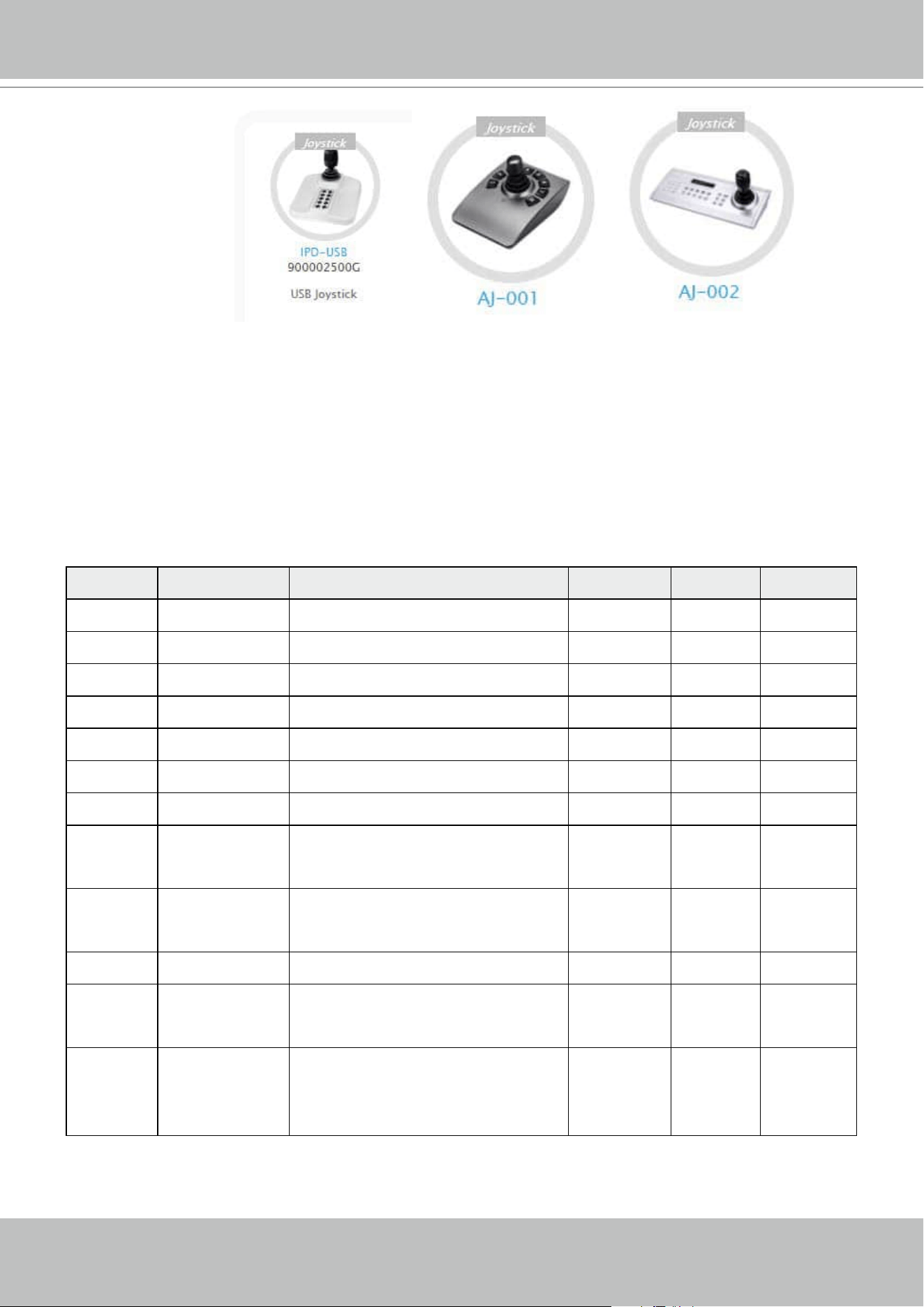
Joystick support
The joystick related operations are listed below:
1. Pan: Continuous move is supported. (joystick X-axis movement)
2. Tilt: Continuous move is supported. (joystick Y-axis movement)
3. Zoom: Continuous move is supported. To zoom in, move joystick Z-axis clockwise. To zoom
out, move joystick Z-axis counter-clockwise.
The Receiver supports VIVOTEK's IPD-USB( 3-axis, 12 buttons), AJ-001(3-axis, 8 buttons), and
AJ-002 (3-axis , 29 buttons) joysticks.
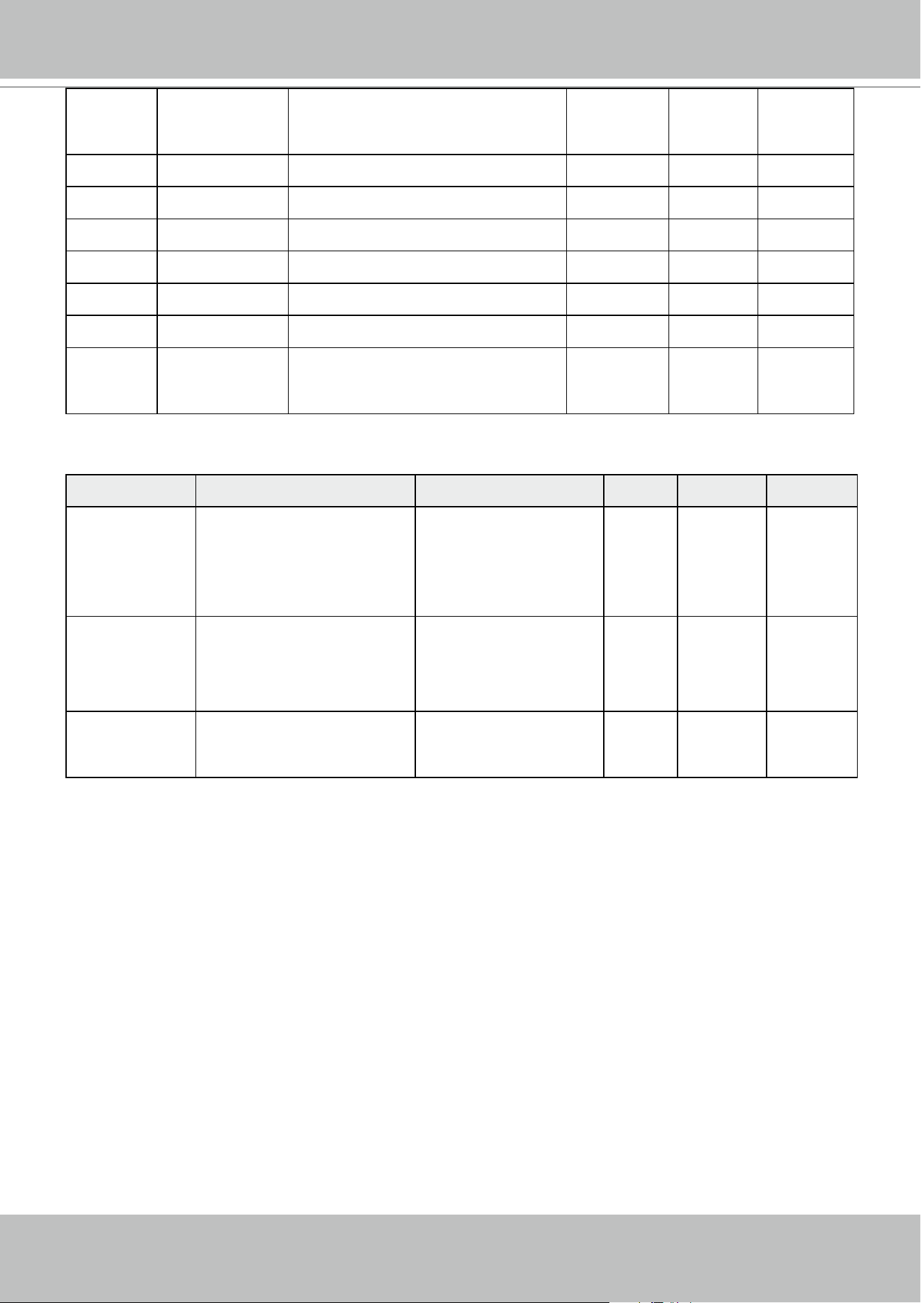
The default button functionality are described below:
Button Function Note Live Setting Playback
1 Pan V V -
2 Patrol Supports the rst patrol V V -
3 Stop V V -
4 Home V V -
5 Focus Near V V -
6 Focus Far V V -
7 Snapshot V V
8 Preset V
V (PTZ
setting/
Motion only
-
9 ~ 17,19 Number 0~9 V
V (PTZ
setting/
Motion only
V
18 ESC V V V
20 Enter V
V (PTZ
setting/
Motion only
21 Full screen When a view cell is selected,
also applies in the Playback.
Press the second time to return
to previous state.
V - V
VIVOTEK - Built with Reliability
30 - User's Manual
22 Manual
Recording
Press once to start manual
recording. Press the second time
to stop.
V - -
23 Change Layout Consecutively changes layout V - V
24 Rewind - - V
25 Pause - - V
26 Play - - V
27 Speed Up - - V
28 Slow down - - V
29 Change focus
view
In live view/playback layout, will
move from top left to lower right,
from view cell to view cell.
V - V
Multi-key Combinations
Button Function NOTE Live Setting Playback
Number+
Enter
Turns a channel into full
view (AJ002 only)
None responsive if
unconfigured channel
number is entered;
e.g., 9+Enter on an
8-CH Receiver.
V - V
Preset+
Number +
Enter
On a PTZ camera view
cell, moves to a preset
position (AJ002 only)
None responsive if
unconfigured position
number is entered
V
V (PTZ
setting/
Motion only
-
Preset +
Number
On a PTZ camera view
cell, moves to a preset
position (AJ001)
None responsive if
unconfigured position
number is entered
V
V (PTZ
setting/
Motion only
-
VIVOTEK - Built with Reliability
User's Manual - 31
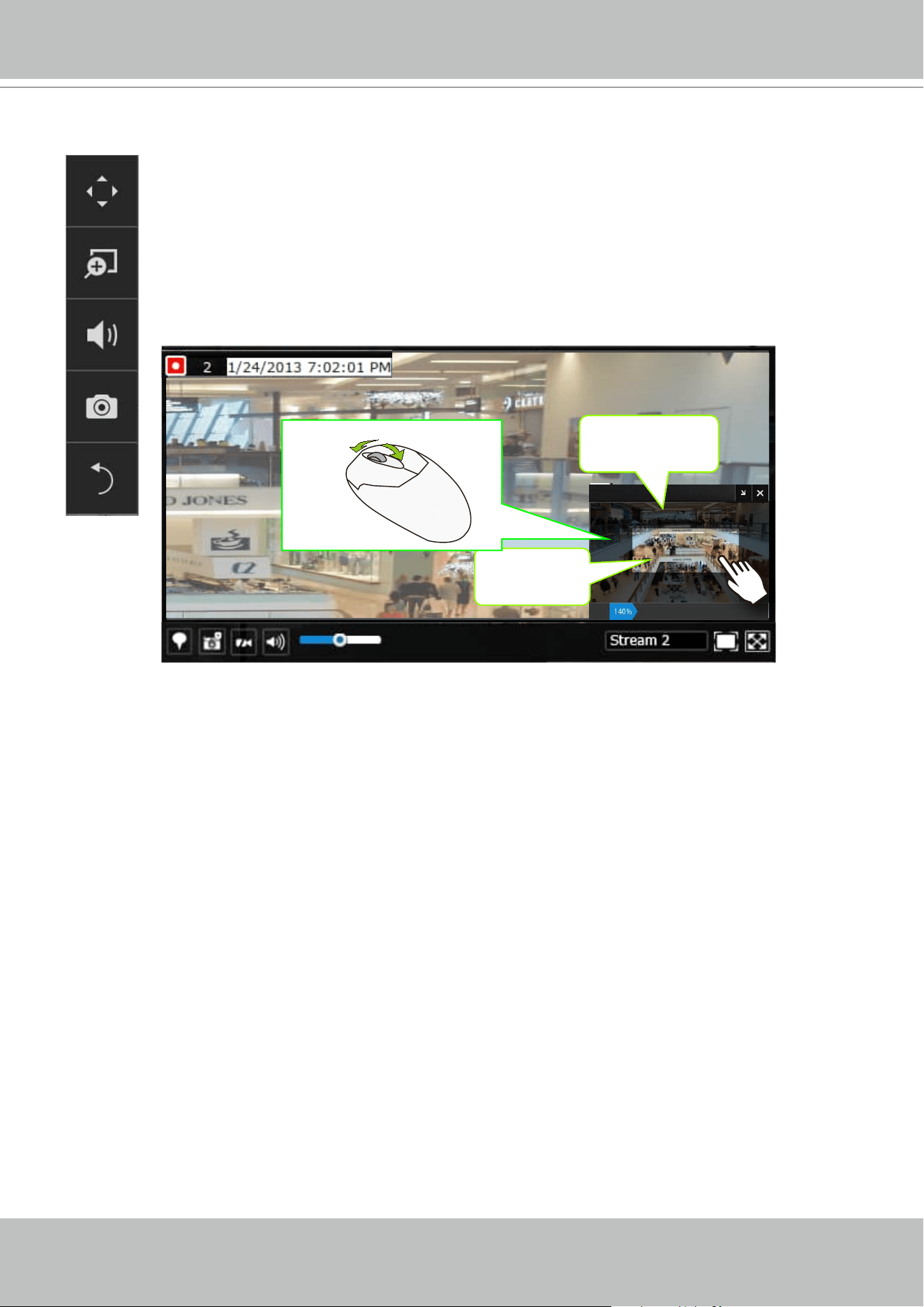
2-2-2. Digital Zoom Panel
Digital zoom is a function that allows an operator to zoom in or zoom out on a live
video.
When activated, a Global view window will appear at the lower right of the view cell
as shown below. You can display only a portion of the complete video frame as an
area of your interest. Using a click and drag on the ROI window, you can instantly
move to other areas within the video frame. Use the zoom ratio pull bar at the bottom
to change the zoom ratio. You may also move the ROI around by clicks and drags.
Global view
ROI
Zoom In Zoom Out
Note that not every camera supports the PiP function.
VIVOTEK - Built with Reliability
32 - User's Manual
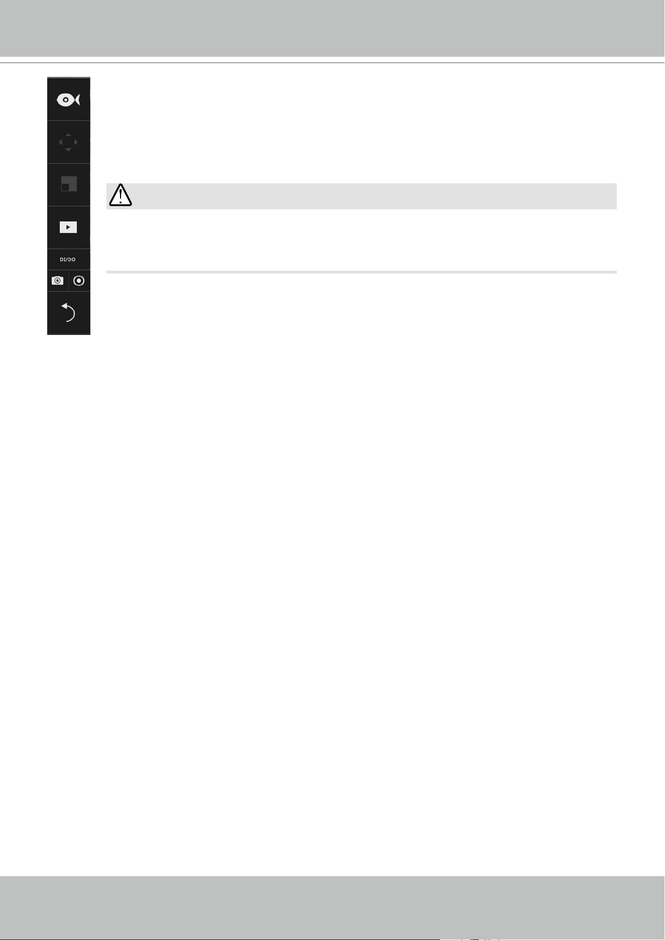
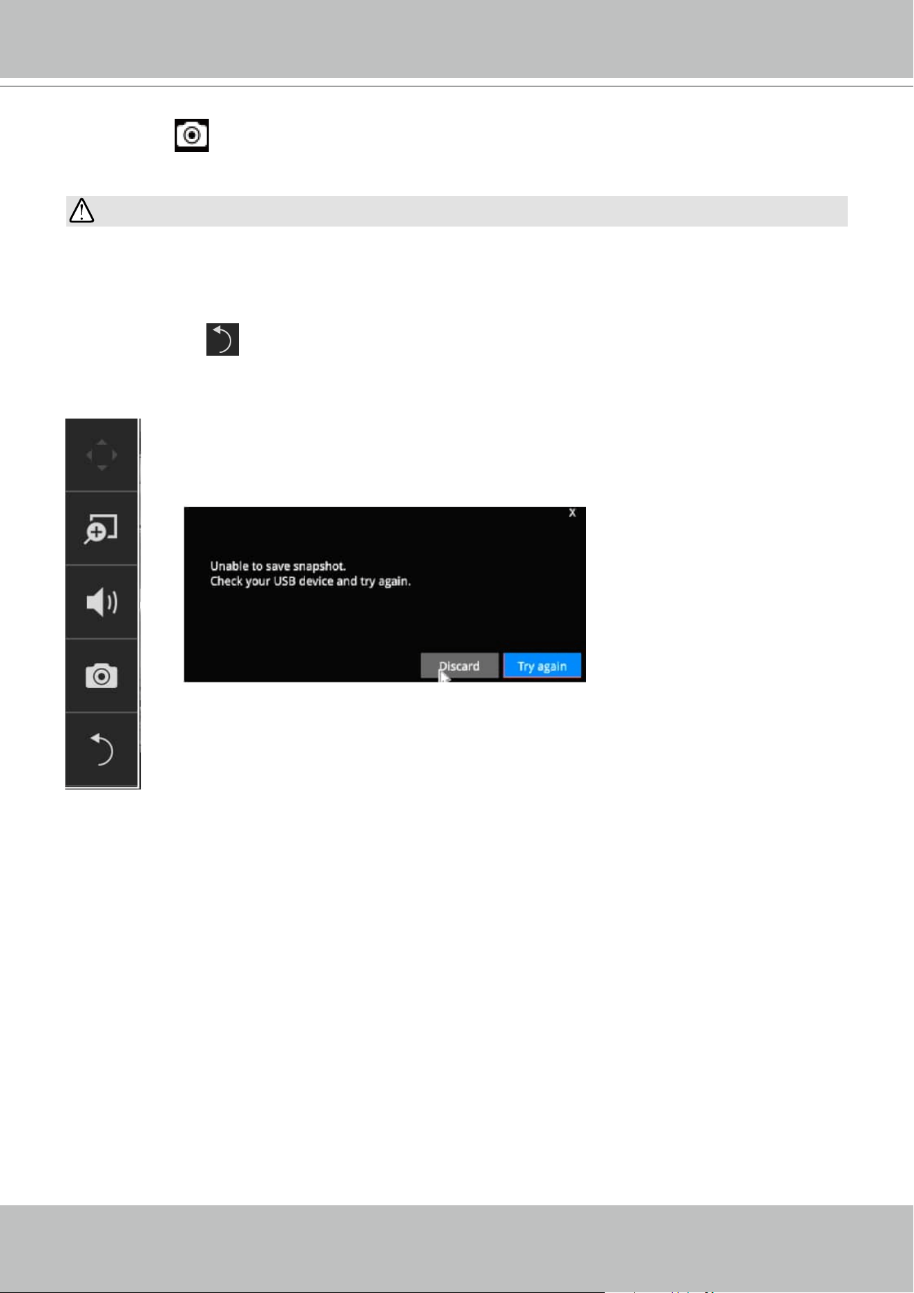
2-2-3. Others
1. Snapshot : is used to take a snapshot from the camera currently selected. Note that this
function only saves the snapshot (in JPEG) to a USB thumb drive.
The USB thumb drive has to be one that is formatted in FAT format.
2. Return button
: Click to return to the LiveView window.
IMPPORTANT:
VIVOTEK - Built with Reliability
User's Manual - 33
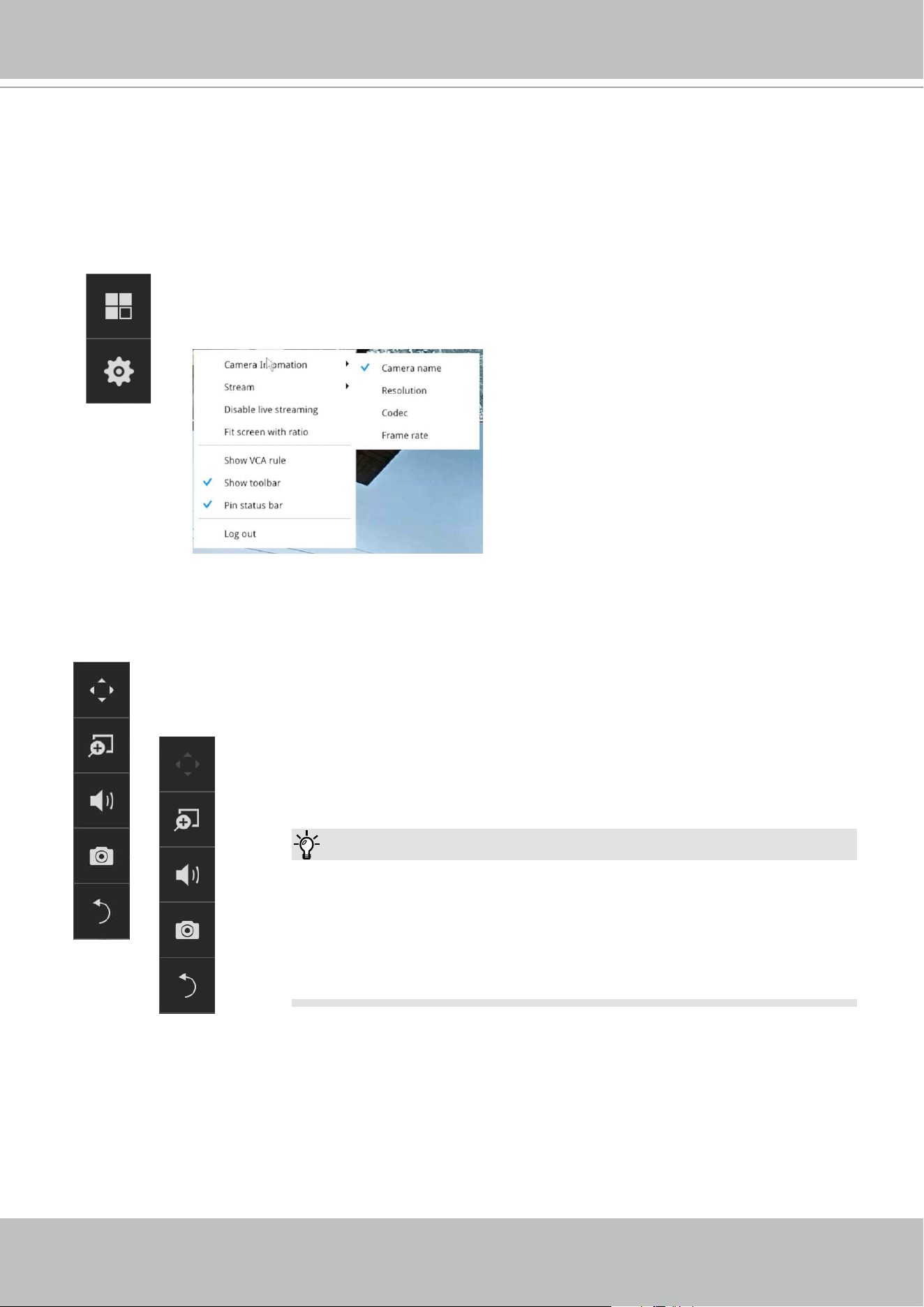
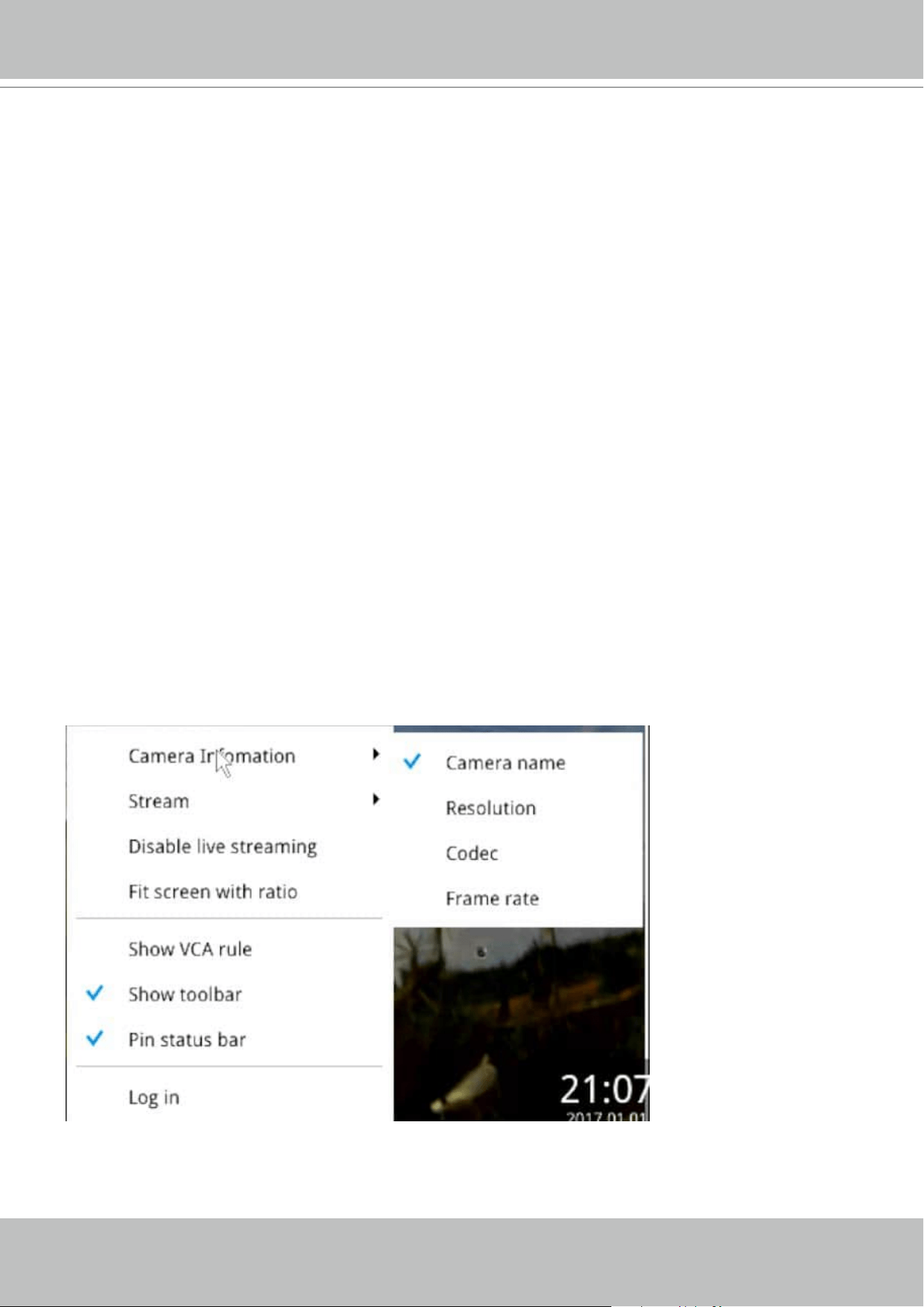
2-2-4. Right-click Commands
Left-click to select a camera. Right-click to display the selection menu.
1. Camera information: Click to display camera name, resolution, codec, or frame rate on the
view cell. The information will display on the upper left corner of a view cell.
2. Stream: Default is enabled. The Auto adaptive stream automatically polls a video stream of
a smaller resolution (changing the resolution of stream #2) in order to reduce the streaming
eorts. For example, when a view cell is placed in a 3x3 monitor layout, it may not be
necessary to stream the video in its full resolution. In a full view, the system displays a video
in its full resolution. Due to the size of view cells on your monitor, when in a multi-cell layout,
the system automatically polls the camera for a smaller resolution stream.
The Auto adaptive stream feature can be disabled if you prefer consistent display resolution.
3. Disable live streaming: Use this to disable the current live streaming.
4. Fit screen with ratio: The Receiver server automatically optimizes the display camera view
cells. However, you can still select this option to display the camera's original aspect ratio: for
example, the original video feed can be 4:3. Without the t screen, every camera's image will
be expanded to ll the view cell.
5. Show VCA rule: If you have congured the video analytics rules on the camera, enable this
to display the VCA rules detection lines and zones.
6. Show tool bar: You can hide the tool bars by deselecting this option.
7. Pin status bar: You can hide the time stamp bars by deselecting this option.
8. Log in: Log in to enable system conguration.
VIVOTEK - Built with Reliability
34 - User's Manual
Chapter Three
Conguation Using the Local Console
The Main Control Portal
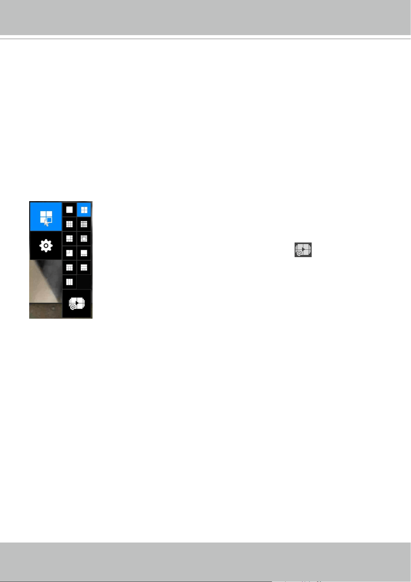
3-1. Layout
The rst functional button is Layout. You can select the 1x1, 2x2, 3x3, 4x4,
1M+5, 1M+12, 1M+31, 1P+3, 1P+6, 2P+3, 3V layout as the screen display.
If you select the single view layout, the rotation button
will appear.
Click the rotation button below to let the system swap the display of dierent
cameras by every 10 seconds. The rotation speed is congurable via Settings
> System > Display.
Move your mouse cursor across the screen to display the portal.
VIVOTEK - Built with Reliability
User's Manual - 35
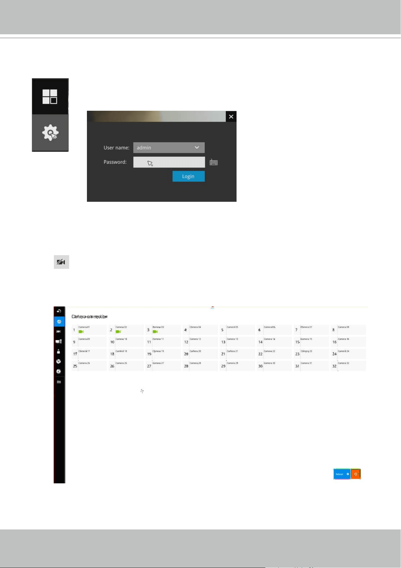
3-2. Settings
Click the Settings button to start the camera and system settings window. A
conrm box will prompt. Enter User name and Password to proceed.
The system will default to the overview page displaying the camera connection statuses.
An empty position will be left in blank, and a disconnected camera will be indicated as
.
The Reboot, and Power-down buttons are also available on this page.
3-2-1. Settings - Overview
VIVOTEK - Built with Reliability
36 - User's Manual
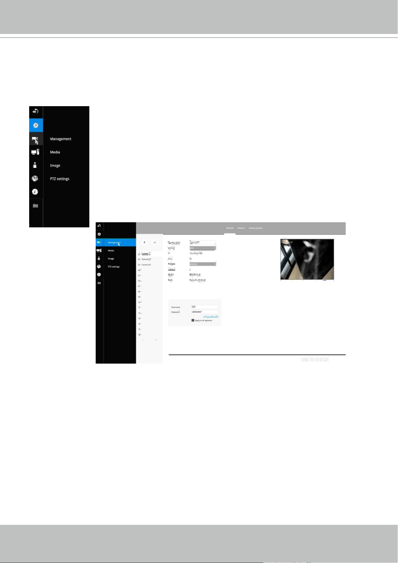
On the camera Management page, you can congure the following:
1. Recruit or disband cameras.
2. Assign User name and Password, or apply the credentials to all cameras in
your conguration.
3. Change the Network settings.
4. Change the cameras' positions on the layout screen.
3-2-2. Settings - Camera - Management
The Camera menu provides access to Management, Media, Image, Motion detection, and
PTZ settings pages.
VIVOTEK - Built with Reliability
User's Manual - 37
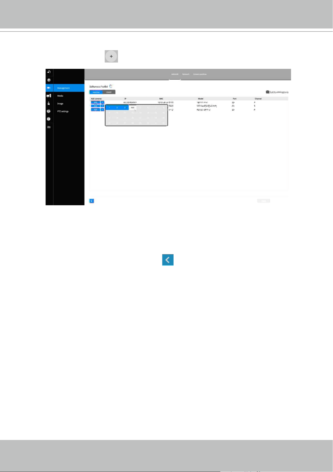
To recruit cameras:
1. Click on the Add button. A list of cameras in the same subnet will appear.
2. Click the Add button, the camera will be placed at an unoccupied position. You may
also expand the menu on the side of the Add button to select a position number.
3. When a camera is added, it should appear on the graphical placement below.
4. Click the Apply button after you added cameras.
5. You may click the page back button
to return to the previous window.
VIVOTEK - Built with Reliability
38 - User's Manual
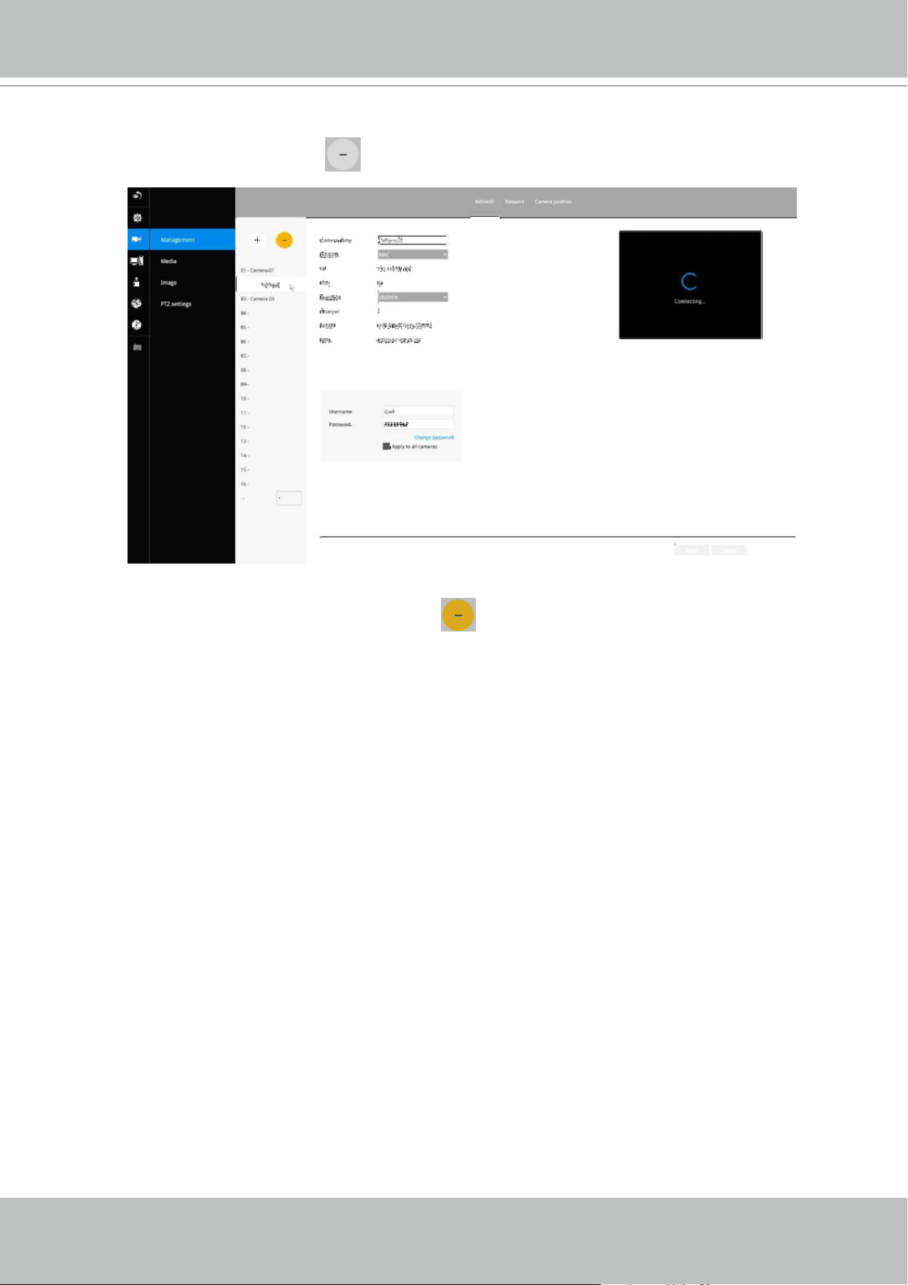
To disband cameras:
1. Click on the Remove button. A list of cameras in your conguration will appear.
2. The Remove button will turn yellow . Mouse over to the camera you want to
remove, and its entry will display the Remove message.
3. Click on the Remove message. The camera should then disappear from the camera
list. The live stream coming from that camera will also be discontinued.
VIVOTEK - Built with Reliability
User's Manual - 39
Note the following when using RTSP connections:
1. RTSP cameras do not support event recording in the Schedule settings.
2. RTSP cameras do not support FTP, Camera DO, and PTZ as the Alarm
action.
3. RTSP cameras do not support camera's related settings such as Network,
Video, Audio, and Display congurations.
4. RTSP cameras will be indicated by an RTSP tag in the device list.
5. RTSP cameras do not support Motion detection conguration.
6. RTSP cameras can not be selected as an alarm trigger.
For legacy cameras, the receiver supports RTSP connections since rmware
release revision 2.6.x.
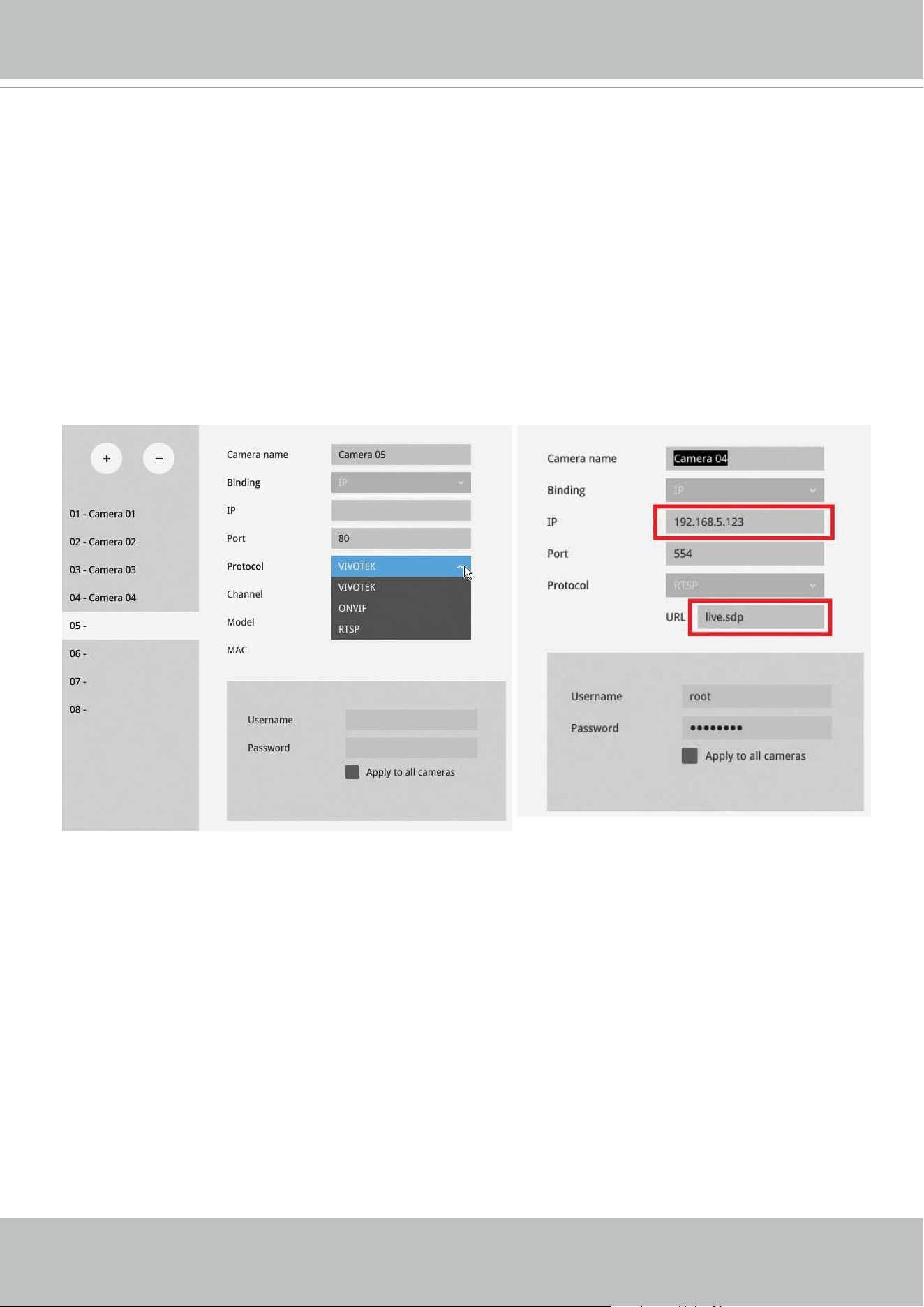
To manually add a legacy camera,
1. Select an empty camera entry,
2. Click the Add button,
3. Select RTSP as the protocol.
4. The original rtsp address is: rtsp://<ip address>:<rtsp port>/<access name
for stream 1 to 3>. For example, when the access name for stream 1 is set
to live.sdp:
rtsp://192.168.5.151:554/live.sdp.
However, you only need to enter
IP address and "live.sdp" in the URL eld.
The system automatically lls in the other parameters.
VIVOTEK - Built with Reliability
40 - User's Manual
In Media > Stream managemeent page, the related Video, Audio, and stream
conguration for RTSP cameras can not be edited. The RSTP cameras will
be tagged.
VIVOTEK - Built with Reliability
User's Manual - 41
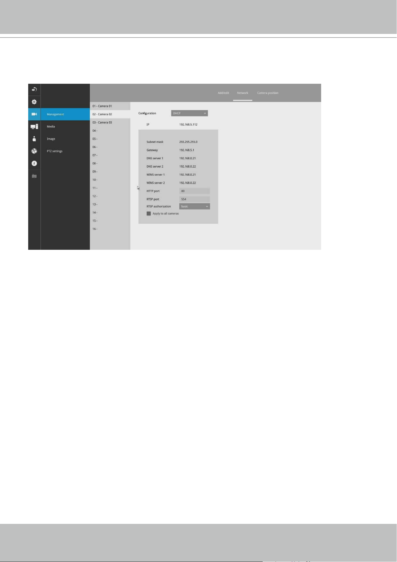
Network
On the Network tabbed window, you can congure the network type, IP address, and the
connection ports for video streaming.
You can select DHCP as the method for cameras to acquire IP addresses, or you can manually
congure static IPs for a single or all cameras. Using static IPs is recommended. Although the
Receiver can remember the MAC addresses of cameras, if IPs are changed under the DHCP
conguration, your Receiver may still fail to connect the cameras. Please consult your network
administrator for details about network settings.
It is usually not necessary to change port numbers for the HTTP and RTSP ports unless there is
a conict in your network environment.
VIVOTEK - Built with Reliability
42 - User's Manual
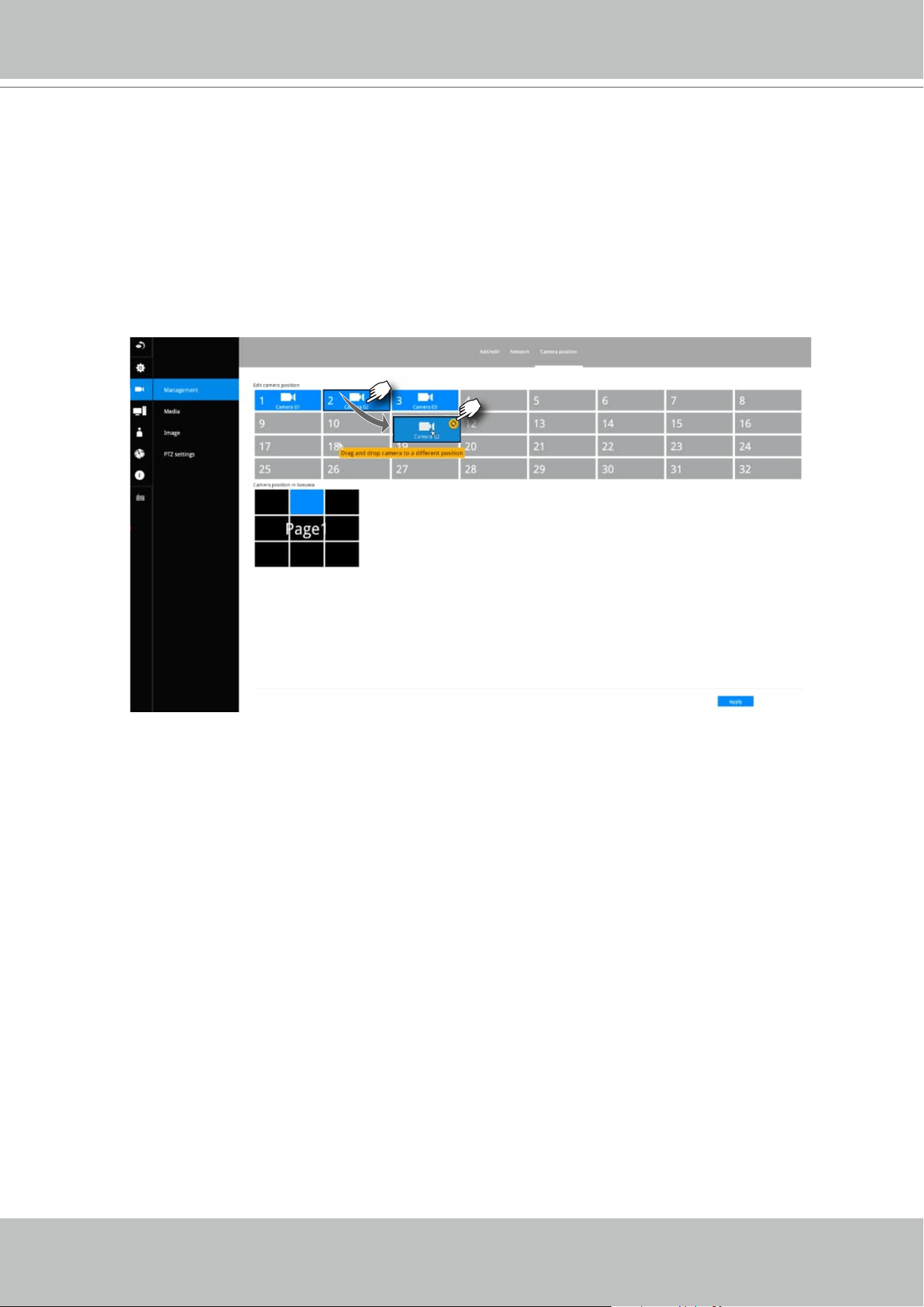
Camera position
To change a camera's position on the Liveview layout, click and drag a camera to an
unpopulated position. Note that you cannot swap the positions of two cameras by
dragging a camera onto a position already populated by the other. Also, the camera
index number on the management list is not aected by the change of positions.
Click the Apply button for the conguration change to take eect. The position screen
displays the current layout on the Liveview screen.
VIVOTEK - Built with Reliability
User's Manual - 43
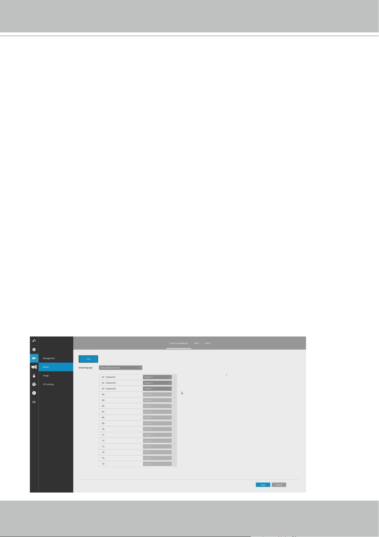
3-3-1. Settings–Camera–Media
The Main stream is set for higher video resolution & Network bandwidth use. The Sub
stream requires lower video resolution & Network bandwidth. Users can not associate
individual camera stream with either the Main or Sub stream.
• Main stream: the 1st stream of camera with H.265/1080p /4Mbps/max frame rate.
• Sub stream: the 2nd stream of camera with H.264/360P/1Mbps/max frame rate
• If the connected camera does not support the values described above, the Receiver will
take the value close to the specications (resolution/ bitrate)
• The Main stream is applied with 2x2 or other layout of a larger view cell.
• The Sub stream is applied with 3x3 or other layouts of a smaller view cell.
On a local console, the P (Panoramic or M (Middle) view cell will display the Main stream.
For Playback:
Only the Main stream is selected for live display. The exported clip le should be the same
as selected as the stream type. The Main stream will be the default.
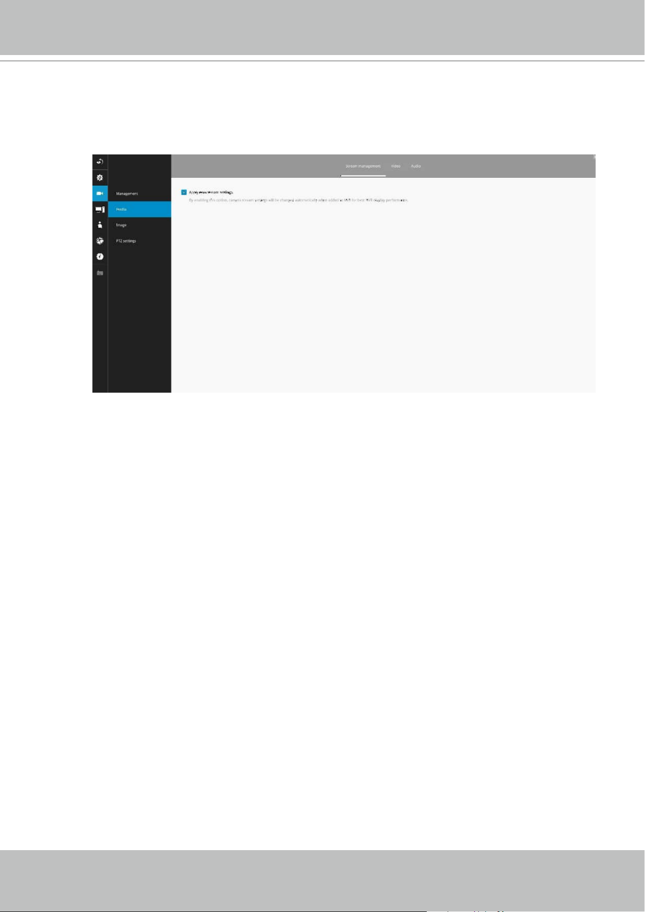
The receiver automatically changes camera stream settings when cameras are added.
If users want to manually congure camera stream setting, they can disable this function.
The default for the automatic conguration is,
• Main stream: H.265 1080p
• Sub stream: H.264 360p
On a web console, the Main stream is displayed on a 1x1 layout. The Sub stream is
displayed on other layouts.

VIVOTEK - Built with Reliability
44 - User's Manual
The receiver adaptively selects to display a video stream of a dierent resolution when it is
displaying on a smaller view cell or a full screen.
.
VIVOTEK - Built with Reliability
User's Manual - 45
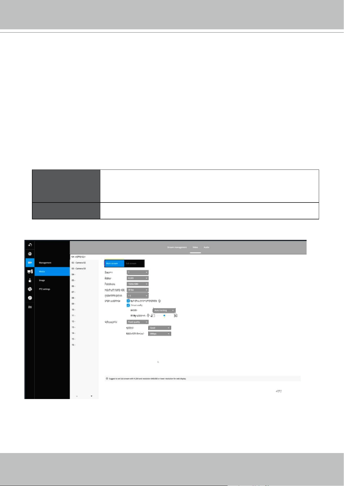
Video
The Video window allows you to congure all video streams (the no. of stream available can be
dierent for dierent models). You can congure the following:
1. Codec: video compression codec in H.264, MPEG-4, or MJPEG. Note that MPEG-4 is not
supported for Liveview.
2. Frame size: video resolution. Note that due to the limited CPU resources, you may not be
able to change the resolution to a very high value, e.g., 5MP in the 1920x1920 resolution.
3. Maximum frame rate: the highest frame rate.
4. Intra frame period: How often an I-frame will be inserted into the video stream.
5. Smart Stream II: Some newer camera models come with Smart Stream features. Please refer
to the next page for detailed information.
6. Video quality: You may either select Constant bit rate or Fixed Quality as the dening rules for
video transmission:
Constant bit rate Places a packet size threshold on video frames; This guarantees
the frame rate per second performance, yet image quality can
be compromised if bandwidth is not sucient in your network
environment.
Fixed Quality Guaranteed video quality, and to ensure image quality, some frames
may be dropped when bandwidth is not sucient.
When done with the conguration, click the Apply button.
VIVOTEK - Built with Reliability
46 - User's Manual
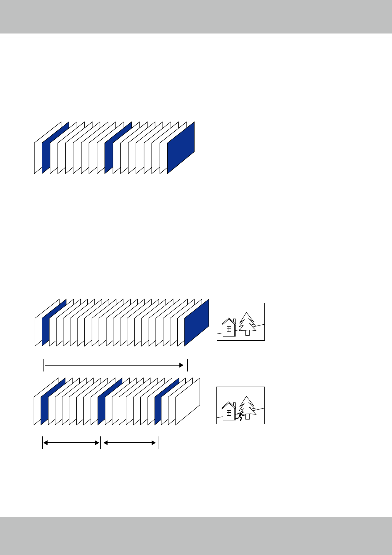
■ Dynamic Intra frame period
High quality motion codecs, such as H.265, utilize the redundancies between video frames to deliver
video streams at a balance of quality and bit rate.
The encoding parameters are summarized and illustrated below. The I-frames are completely self-
referential and they are largest in size. The P-frames are predicted frames. The encoder refers to the
previous I- or P-frames for redundant image information.
P I P P P P P P P P P P P P P P P P P P P I
P I P P P P P P P I P P P P P P P I
Static scene
Activities
P P P
P I P P P P P P P I P P P P P P P I
By dynamically prolonging the intervals for I-frames insertion to up to 10 seconds, the bit rates
required for streaming a video can be tremendously reduced. When streaming a video of a
static scene, the Dynamic Intra frame feature can save up to 53% of bandwidth. The amount of
bandwidth thus saved is also determined by the activities in the eld of view. If activities occur
in the scene, rmware automatically shortens the I-frame insertion intervals in order to maintain
image quality. In the low light or night conditions, the sizes of P-frames tend to be enlarged due
to the noises, and hence the bandwidth saving eect is also reduced.
Streaming a typical 2MP scene normally requires 3~4Mb/s of bandwidth. With the Dynamic Intra
frame function, the bandwidth for streaming a medium-trac scene can be reduced to 2~3Mb/s,
and during the no-trac period of time, down to 500kb/s.
H.264/265 Frame Types
Dynamic Intra Frame w/
static scenes
Dynamic Intra Frame w/
activities in scenes
VIVOTEK - Built with Reliability
User's Manual - 47
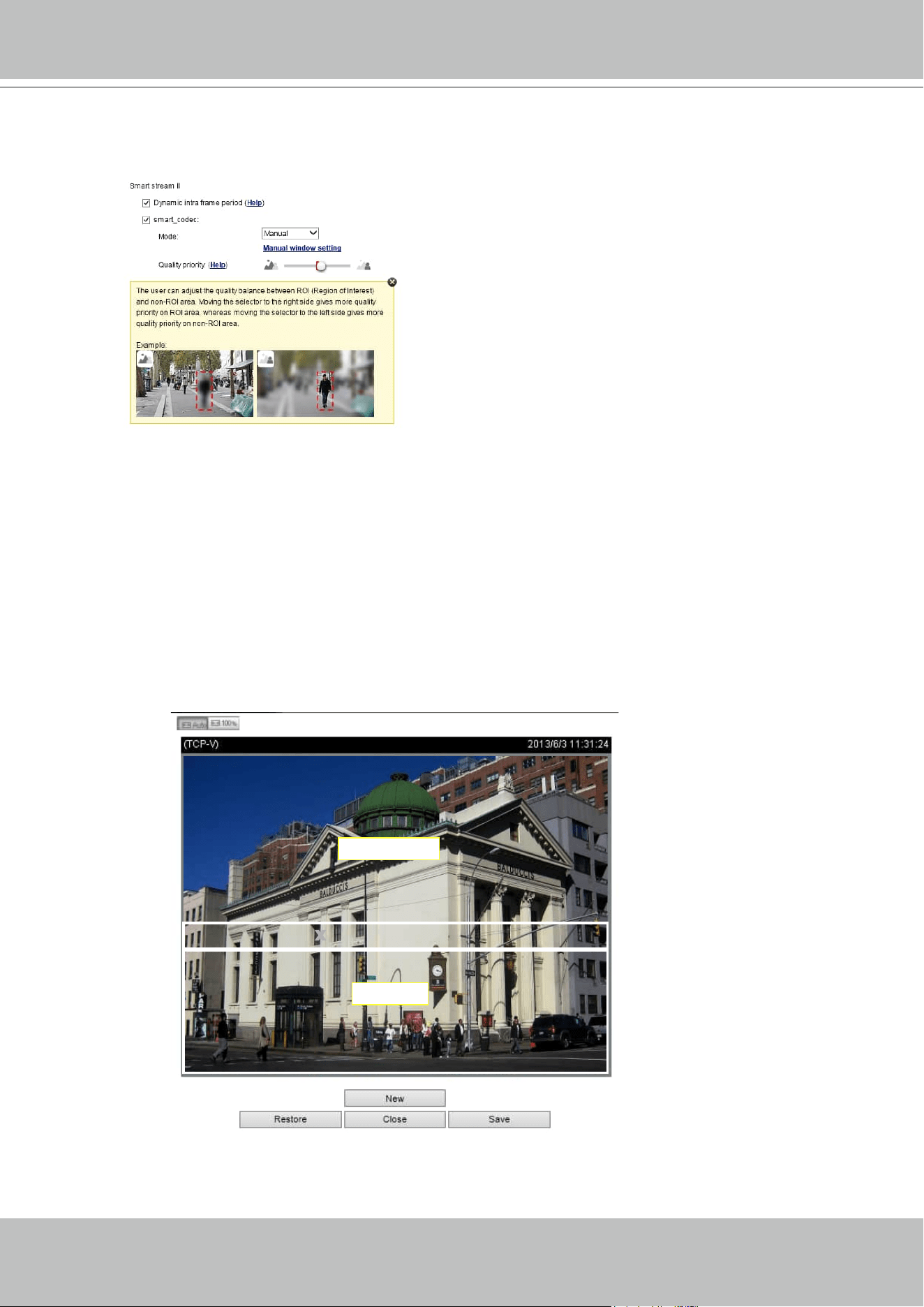
■
Smart codec eectively reduces the quality of the whole or the non-interested areas on a
screen and therefore reduces the bandwidth consumed.
X
ROI_0
X
ROI_0
ROI
non-interested
You can manually specify the video quality for the foreground and the background areas.
Select an operation mode if Smart codec is preferred.
- Auto tracking: The Auto mode congures the whole screen into the non-interested area.
The video quality of part of the screen returns to normal when one or more objects
move in that area. The remainder of the screen where there are no moving objects
(no pixel changes) will still be transmitted in low-quality format.
- Manual: The Manual mode allows you to congure 3 ROI windows (Region of Interest,
with Foreground quality) on the screen. Areas not included in any ROI windows
will be considered as the non-interested areas. The details in the ROI areas will be
transmitted in a higher-quality video format.
As illustrated below, the upper screen may contain little details of your interest,
while the sidewalk on the lower screen is included in an ROI window.
Slide bar to the right - higher quality in the ROI
areas
Slide bar to the left - higher quality in the non-ROI
areas.
VIVOTEK - Built with Reliability
48 - User's Manual
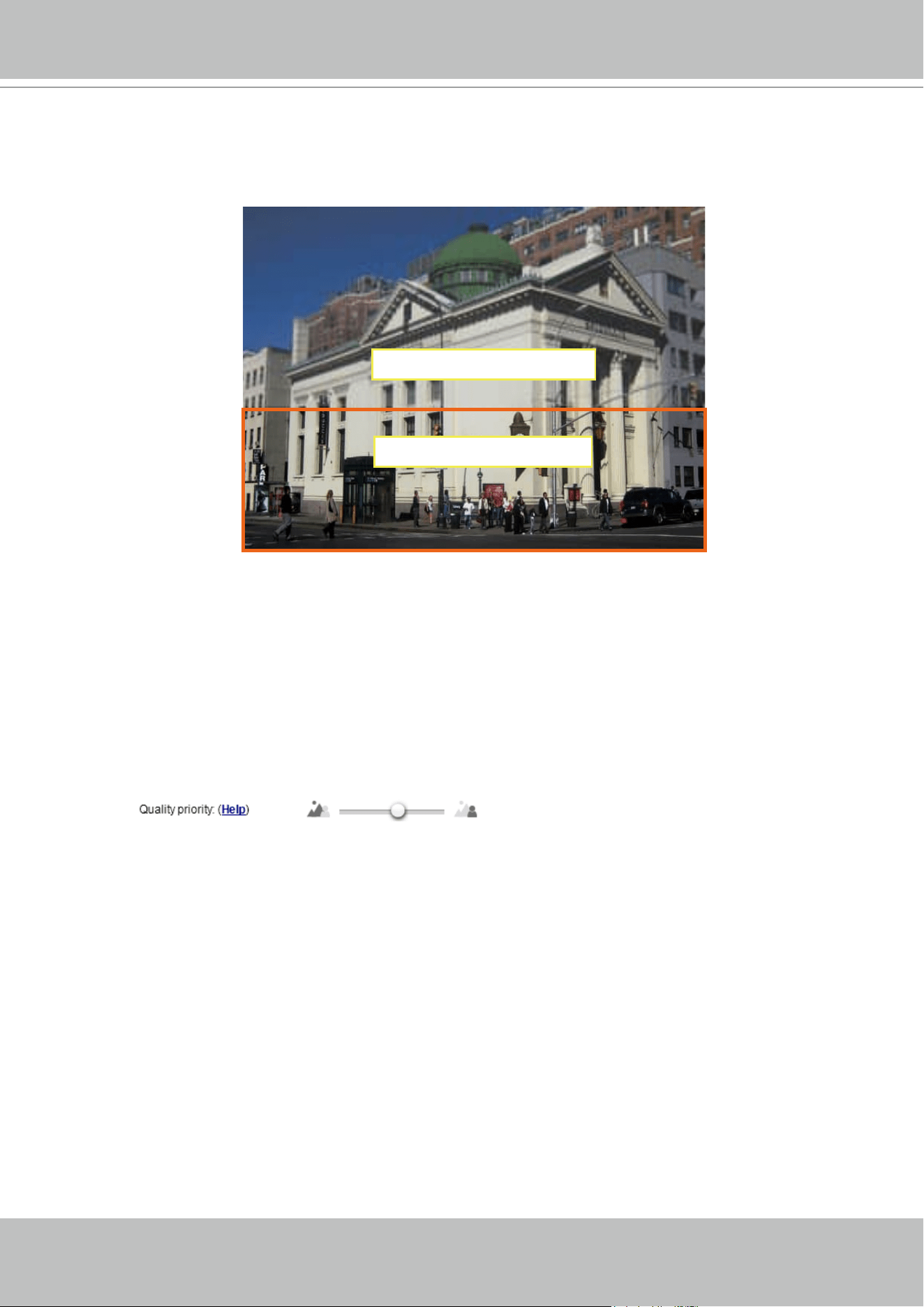
ROI: higher-quality
non-ROI: lower-quality
As the result, the lower screen is constantly displayed in high details,
while the upper half is transmitted using a lower-quality format. Although
the upper half is transmitted using a lower quality format, you still have an
awareness of what is happening on the whole screen.
- Hybrid: The major difference between the “Manual” mode and the “Hybrid”
mode is that:
In the “Hybrid“ mode, any objects entering the non-interested area will
restore the video quality of the moving objects and the area around
them. The video quality of the associated non-interested area is
immediately restored to normal to cover the moving objects.
In the “Manual” mode, the non-interested area is always transmitted
using a low-quality format regardless of the activities inside.
You should also select the Maximum bit rate from the pull-down menu as the
threshold to contain the bandwidth consumption for both the high- and low-
quality video sections in a smart stream.
- Quality priority: Use the slide bar to tune the quality contrast between the ROI
and non-interested areas.
The farther the slide bar button is to the right, the higher the image
quality of the ROI areas. On the contrary, the farther the slide bar button
to the left, the higher the image quality of the non-interested area.
In this way, you may set up an ROI window as a privacy mask by
covering a protected area using an ROI window, while the remaining
screen become the non-interested area. You may then configure the
non-interested area to have a high image quality, or vice versa.
VIVOTEK - Built with Reliability
User's Manual - 49
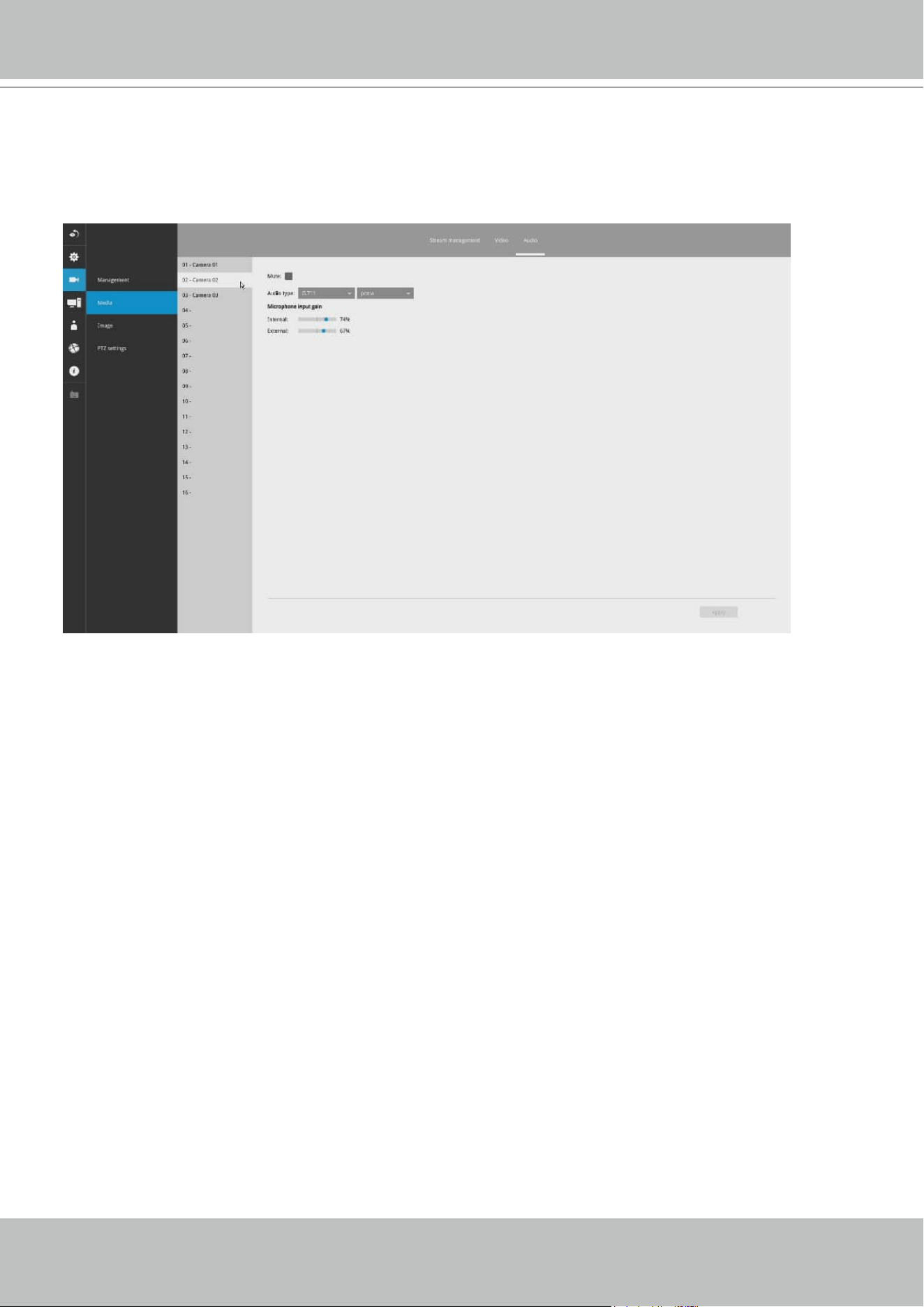
Audio
The Audio window allows you to congure all audio codec, sampling rate, and Microphone input
gains. Depending on design of the camera models, some codecs may not be available. Also,
there are cameras that come without embedded mircrophones.
VIVOTEK - Built with Reliability
50 - User's Manual
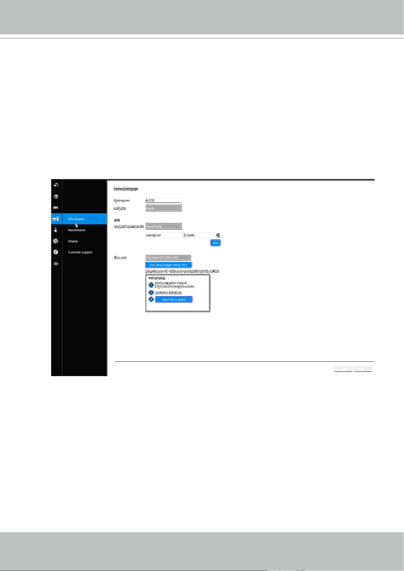
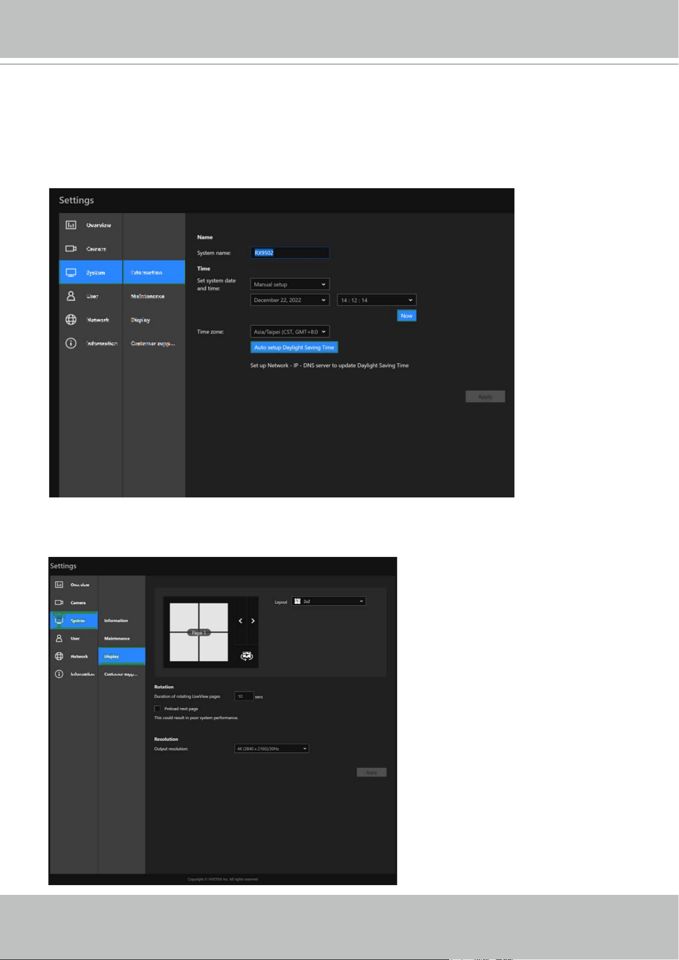
On this window, you can congure the following:
1. Change the system name.
2. Select the UI text language.
3. Congure system time, time zone, and if you are connected to a DNS server where
Auto Daylight Saving time can be applied, you can acquire the associated setting from
a server within your network.
4. Click the Apply button for the conguration to take eect.
Note that if NTP time server conguration (Auto) is preferred, the system will automatically
congure all cameras to be listening to the system, and therefore to the same time server.
3-3-2. Settings - System - Information
VIVOTEK - Built with Reliability
User's Manual - 51
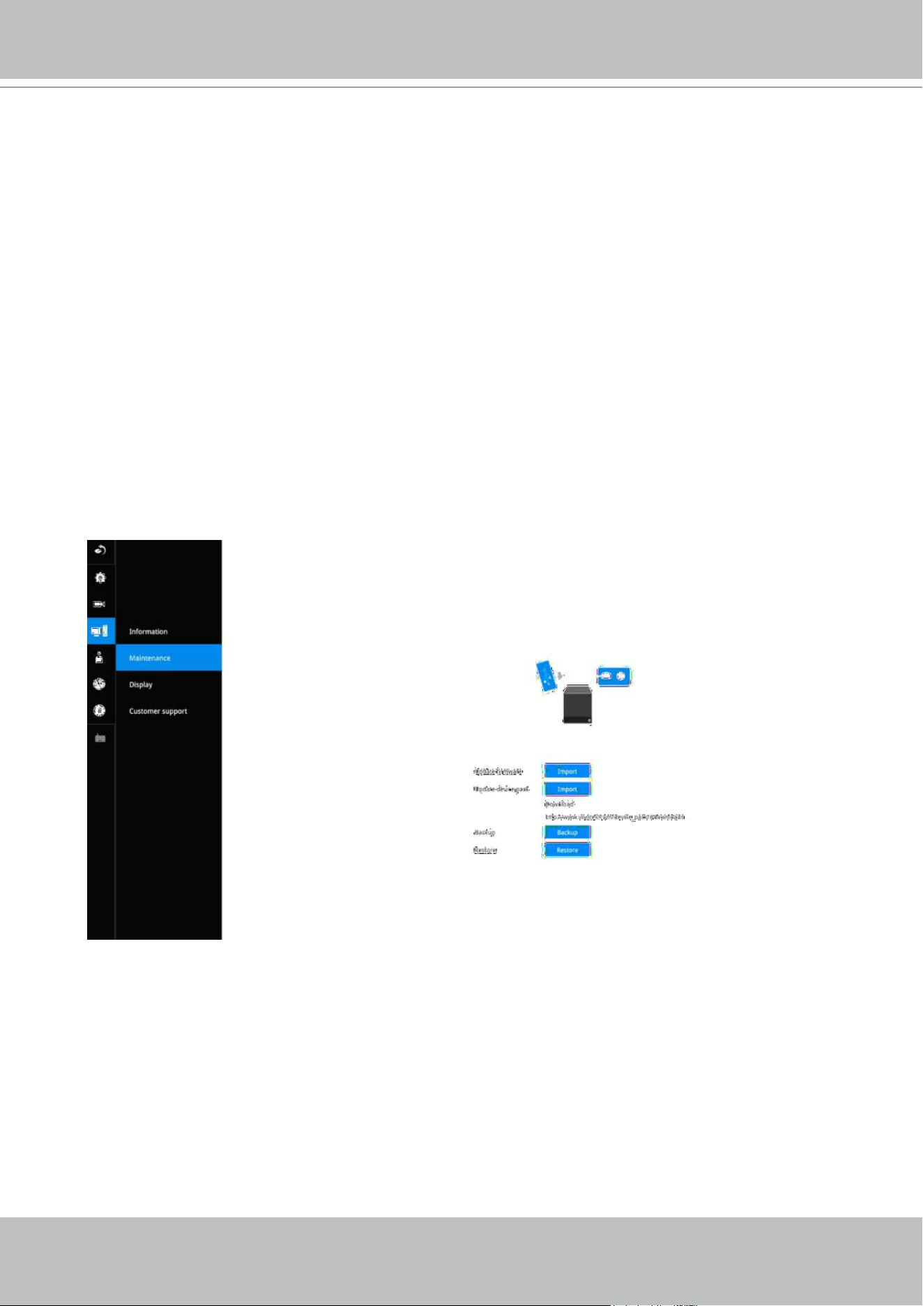
3-3-2. Settings - System - Maintenance
If the need arises for updating system rmware, acquire the update from VIVOTEK's technical
support or download site. Locate the rmware binaries, and click the Import button. The upgrade
should take several minutes to complete. Note that during the upgrade, the live display task will
be interrupted.
On this window, you can perform 4 maintenance tasks:
1. Update rmware - Download rmware and save it to a USB drive in the FAT format, attach
the USB device to the Receiver for rmware upgrade.
2. Update device pack - A device pack allows you to import associated congurations and
parameters for new camera models so that these cameras can be integrated into your
Receiver conguration. The information in the device pack is related to some tunable
parameters.
Note that the backup action does not involve the following:
1. Recorded videos and database,
2. Alarm records, bookmarks, and bookmarked footages.
Select a location for your backup le, then click Save to complete the process. If you back up
to a USB thumb drive, that thumb drive must be formatted using the FAT format.
4. Restore - If you have a previously-saved prole, you can restore your previous conguration.
Click the Restore button.
A le location window will prompt. Locate the backup le, and click Open. The Restore
process will take several minutes to complete, and system operation will be interrupted during
the process.
3. Backup - You can backup your system conguration using the Backup function. Click Backup,
a message window will prompt. Click Save to preserve your system congurations.
VIVOTEK - Built with Reliability
52 - User's Manual
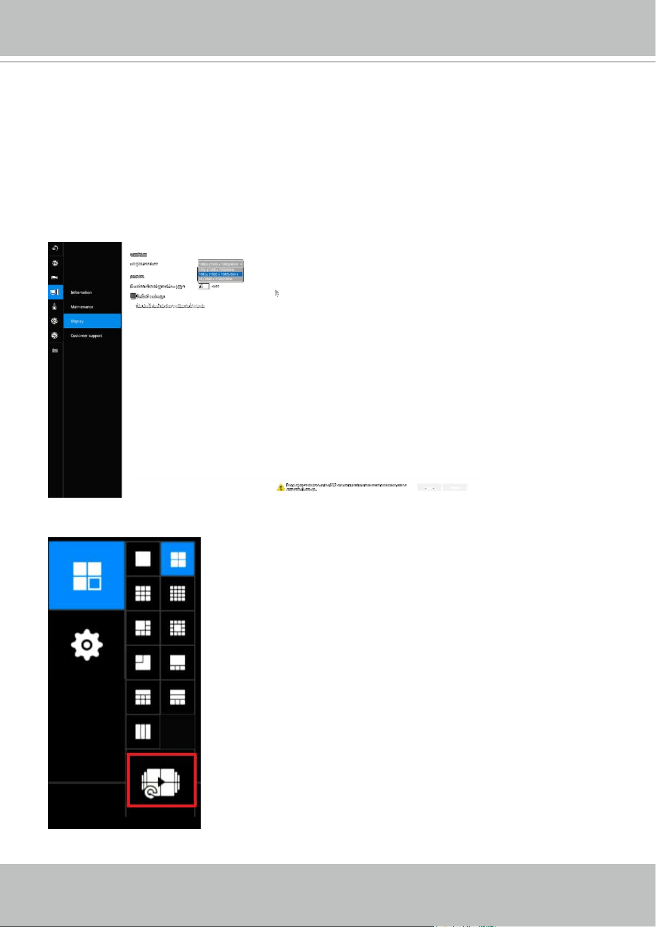
3-3-3. Settings - System - Display
On this page, you can congure the system to consecutively display (rotate) cameras' view cells
on the Liveview window. For example, if you have 8 cameras in 2 2x2 layouts, the rotation can
let you see the live views of all cameras by every few seconds.
You can also enable or disable the Alarm notication.
Output resolution: If your monitor or TV supports the 4K resolution, you can select the 4K
resolution at the frame rate of 30fps. This setting depends on the maximum resolution of your
display device.
To enable the rotate function, click on the rotate button on the layout panel.

VIVOTEK - Built with Reliability
User's Manual - 53
3-4. Settings - User
The User window allows you to change the administrator's password.
1. By default, there is only one user type: Administrator.
2. The administrator users can access all cameras recruited in the conguration.
You can create new users using the add button, and create credentials and designate the
access rights to individual cameras.
It is highly recommended to change the default password to prevent unauthorized access to the
system.
IMPORTANT:
The max. number of characters for the administrator password is 64, with the combination of
alphabetic and numeric characters including [0-9][a-z][A-Z][_][ ][-][.][,][@].

VIVOTEK - Built with Reliability
54 - User's Manual
3-4-1. Login / Logout
Login
1.
Login required to view live streaming: If selected, users will be required to enter his/her
credentials before displaying a live view. If not selected, the Receiver displays live view rst.
Login will be required when performing specic tasks, such as entering the Settings page.
Auto Logout should also be enabled when the receiver can be left unattended for an extended
period of time. Default is 10 minutes.
Camera views will be available for users according to their privilege settings as designated in
the User account conguration. Some camera views will be available for some users, while
others are not.
2. Move authorized cameras to the beginning of live view (regular users only): For users who
have access to specic cameras only, he will be required to enter his credentials before
viewing a live view.
Logout
1. Enable auto logout: By default, a user is logged out automatically after being idle for 10
minutes. If not selected, the Receiver will not log out automatically. A user can only log out
manually.
VIVOTEK - Built with Reliability
User's Manual - 55
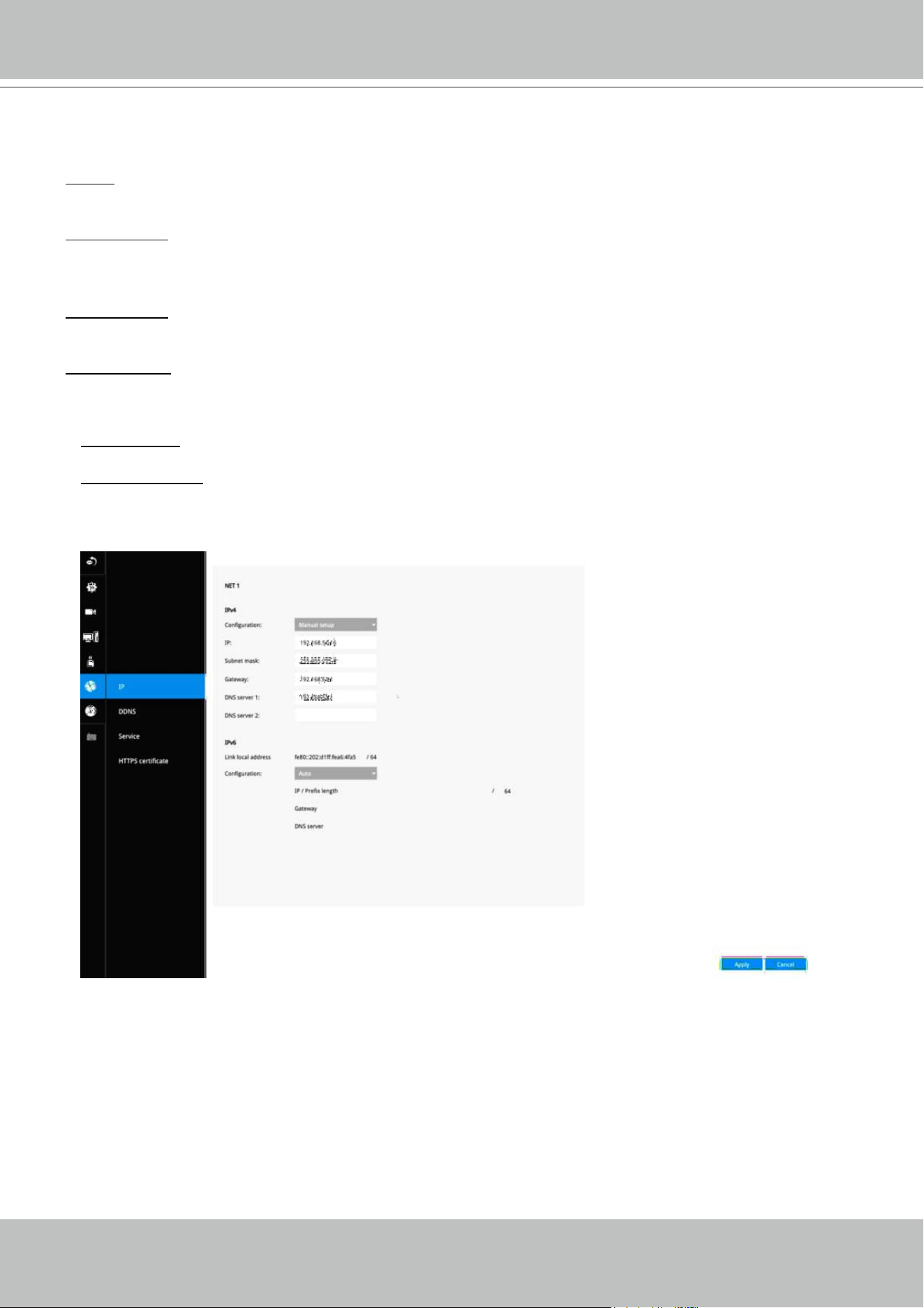
Settings - Network - IP
Primary DNS: The primary domain name server that translates hostnames into IP addresses.
Secondary DNS: Secondary domain name server that backups the Primary DNS.
DHCP: Default is selected, the server obtains an available dynamic IP address assigned by the DHCP
server each time the system is connected to the LAN.
Manual setup: Select this option to manually assign a static IP address to the Network Camera.
Enter the Static IP, Subnet mask, Default router, and Primary DNS provided by your ISP.
Subnet mask: This is used to determine if the destination is in the same subnet. The default value is
“255.255.255.0”.
Default router: This is the gateway used to forward frames to destinations in a dierent subnet. Invalid
router setting will fail the transmission to destinations in dierent subnet.
When nished with the network settings, click on the Apply button.
3-5. Settings - Network
VIVOTEK - Built with Reliability
56 - User's Manual
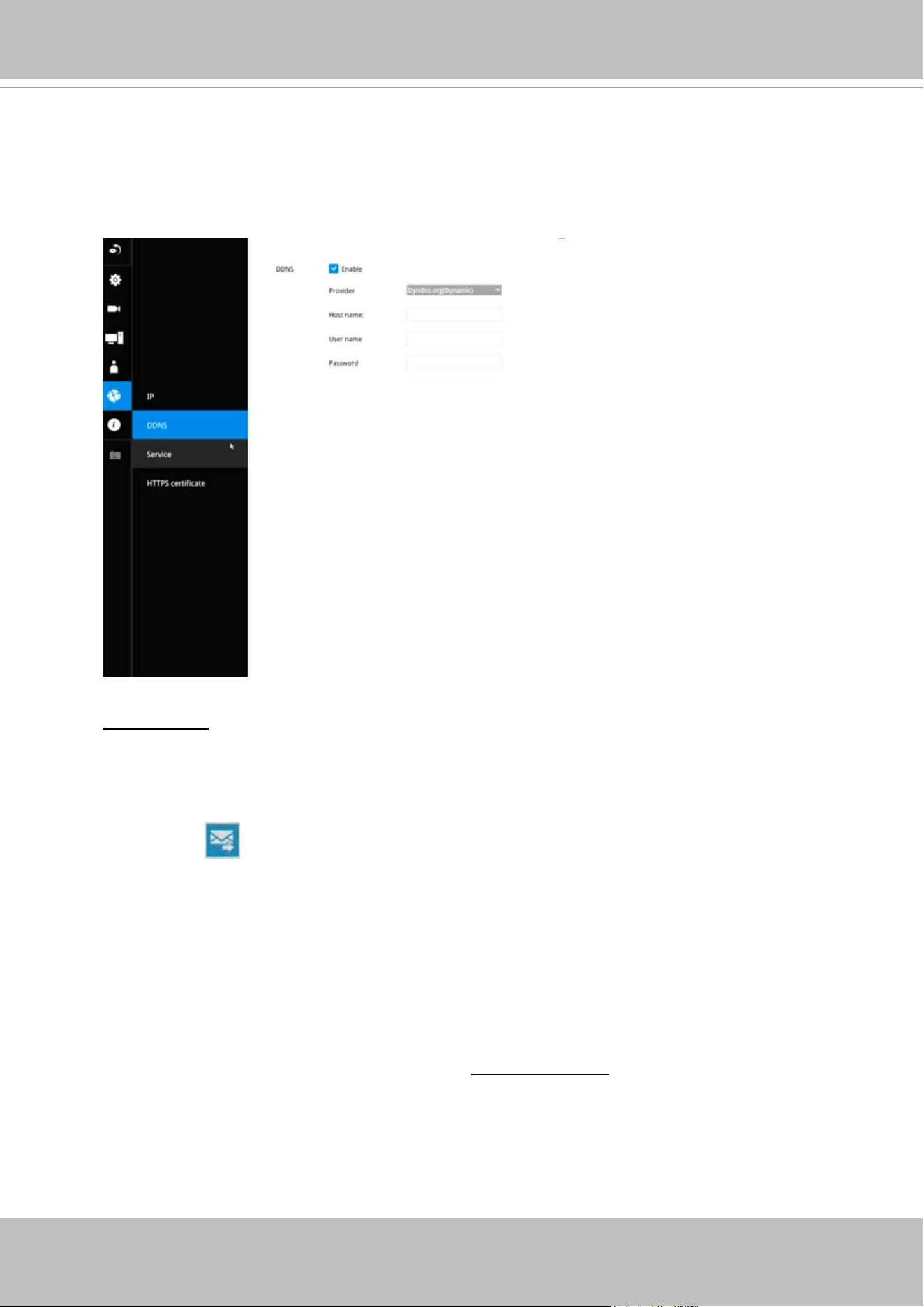
Settings - DDNS
VIVOTEK provides Dyndns.org, as a free DDNS dynamic domain name service for users who
want access from the internet or a domain name service for the Receiver. VIVOTEK maintains
a database of product MAC addresses for the service, and you can apply one domain name for
each Receiver system.
DDNS Enable: Select this checkbox to enable the DDNS setting.
Enter a Host name, Email address, and password twice, and then click Apply to proceed.
Make sure you have internet access.
Click the Register button. The terms of service agreement window is selected from a checkbox at the
bottom. Click
to read the license agreement terms.
When completed, a conrm message will prompt. You will also receive a conrm Email. You can
now access your Receiver system using the xxxx.Dyndns.org domain name address. Note that
access from the Internet should be routed to the private IP assigned to your Receiver, using
methodologies such as port forwarding, etc.
The acceptable characters for email address are: [0-9][a-z][A-Z][!][#][$][%][‘][*][+][-][/][=][?]
[^][_][`][{][|][}][~][.]. Two successive periods, [..], are not acceptable. The address filed can
accommodate up to 256 characters.
Use only alphabetic and numeric characters for the password. The maximum number of
characters is 64.
VIVOTEK - Built with Reliability
User's Manual - 57
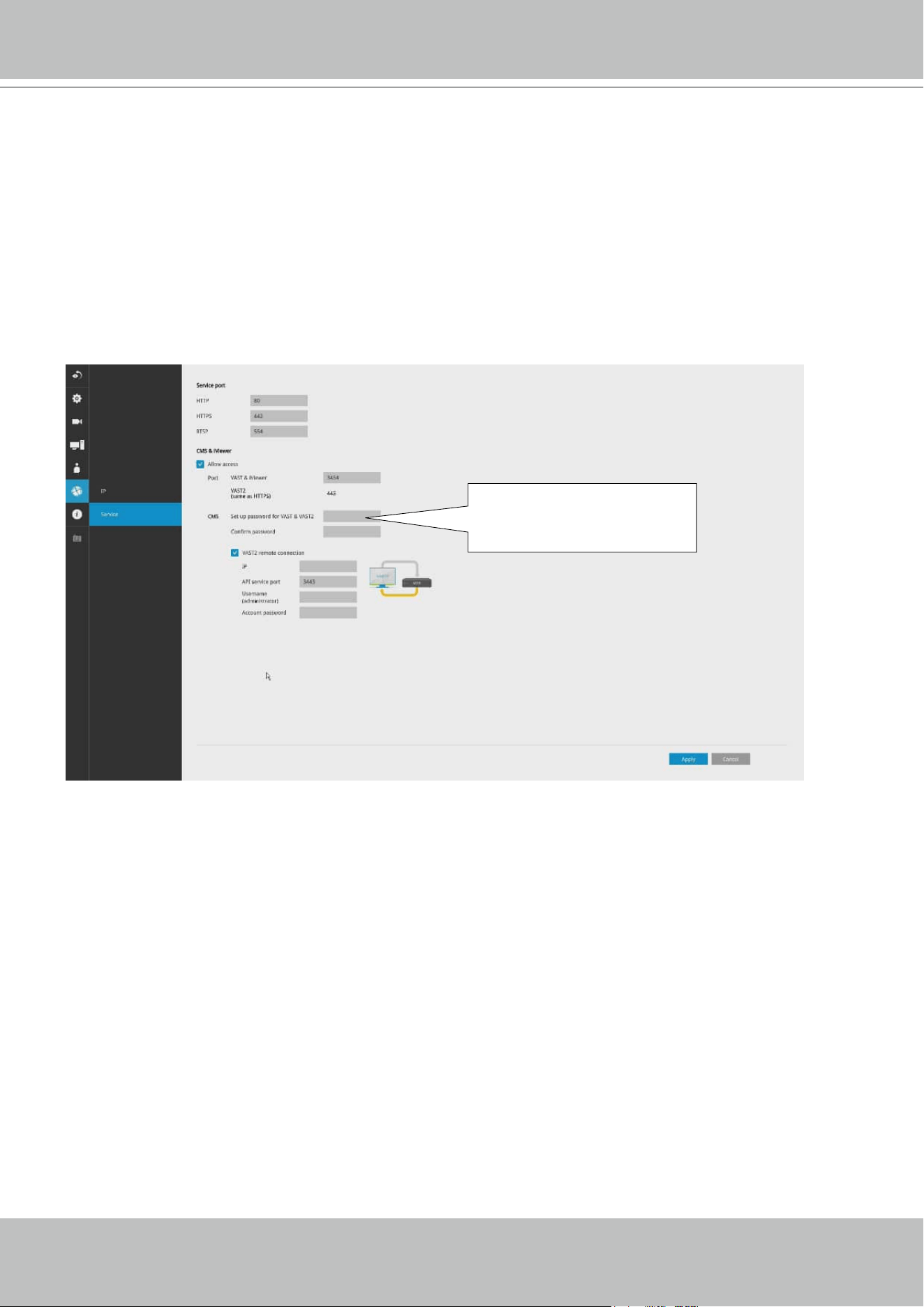
Settings - Service
By default, the Receiver service and video streaming are accessed via HTTP port 80 and
RTSP port 554. You can designate a dierent port number if the need arises. Usually it is not
necessary to change these ports. HTTPS encrypted connection is enabled by default.
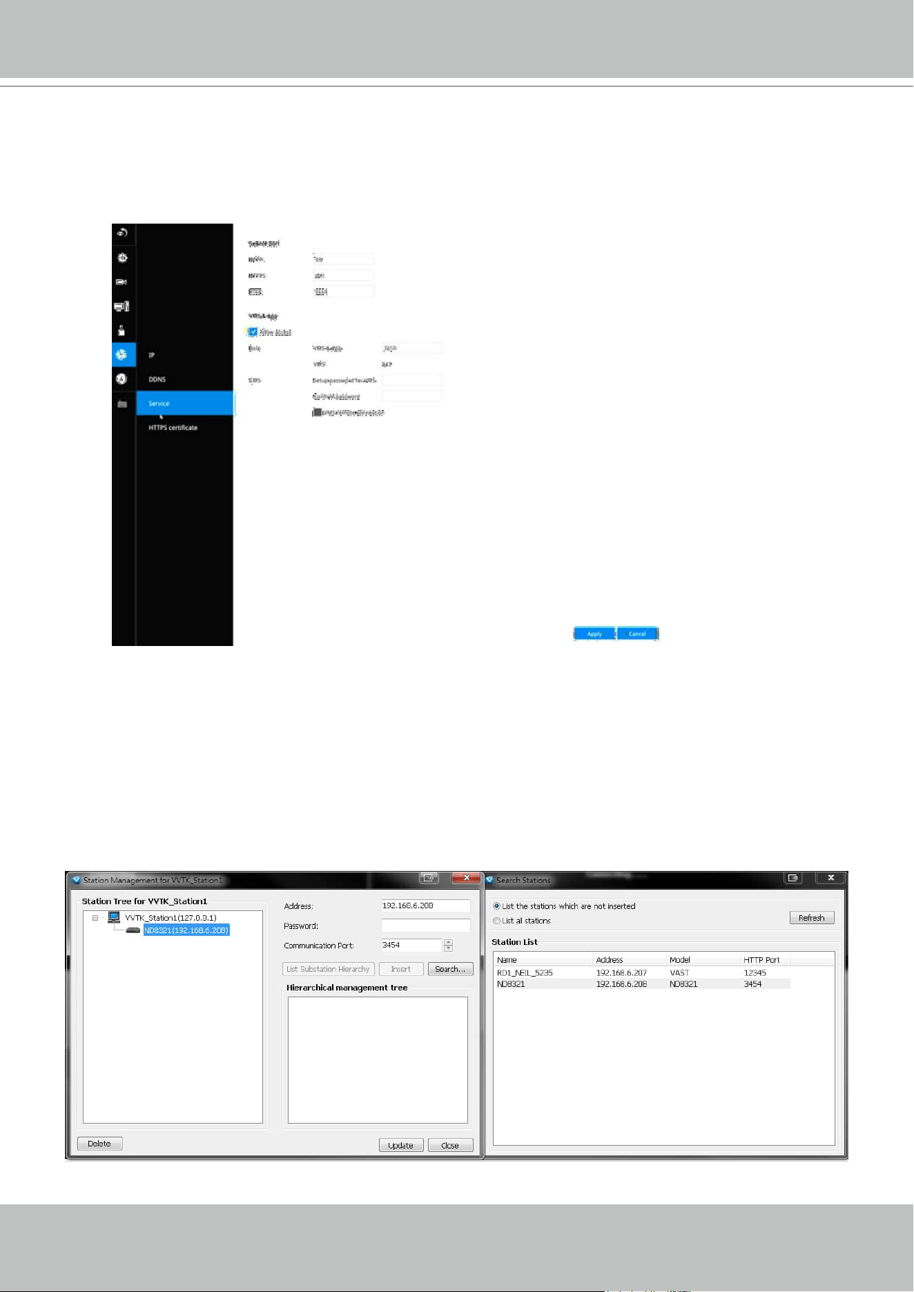
Instead of a web console, you can also access the Receiver and the subordinate cameras
using VIVOTEK's VSS software. The Receiver can be managed as one of the sub-stations in a
hierarchical device structure.
Set up a password for access from the VSS server before you can join the Receiver to a VSS
centralized management conguration. For access from the iViewer, you log in using the same
user name and password for the login to the Receiver.
Below is the screen showing the sub-station recruitment process from a VSS server.
VIVOTEK - Built with Reliability
58 - User's Manual
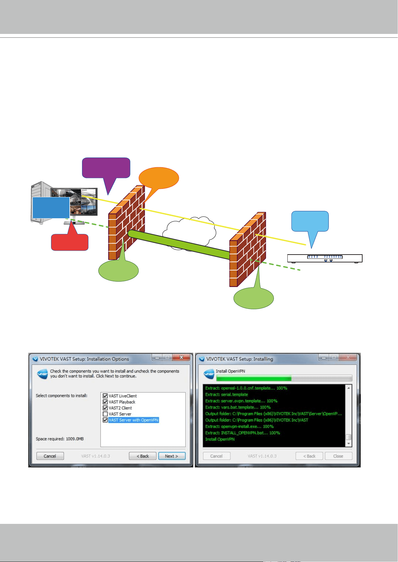
NAT-traversal with OpenVPN
You can select the "VSS Server with OpenVPN" option when installing the VSS server. A remote
connection from Receiver via a 3G/4G/LTE network can be made through an OpenVPN tunnel.
When the OpenVPN option is selected, an OpenVPN server will be installed with the VSS server.
HMAC authentication and TLS encryption over an encrypted UDP connection are made effortlessly us-
ing the traversal methodology.
The sample installation screens are shown below:
VSS
Camera 01
Camera 02
Camera 03
Camera 04
Camera 06
Camera 05
Camera 07
Camera 08
Camera 09
Internet
HTTPS connection
OpenVPN tunnel
Port
Forwarding
Establish
VPN tunnel
Port
Forwarding
Register
Substation
Fetch CA/
Cert/Key
RESTful
API Server
Tunnel
message
NVR
VSS auto connection

VIVOTEK - Built with Reliability
User's Manual - 59
With a remote VSS instance that needs to access the Receiver via the Internet, you can enter
its public IP address and credentials. The Receiver runs an Open VPN client that makes remote
connection via the RESTful (Repretational State Transfer) API (Application Programming
Interface) service to a VPN server running on the remote site. The applicable service port
number ranges from 1 to 65534. Default is 3443. The Receiver automatically registers with CA
cert key and becomes with sub-station over a VPN tunnel. Once set, the VSS can automatically
connects the Receiver.
A public IP or domain name must be congured on the VSS server for the access through the
Internet. The IP or domain name can contain alpha-numeric characters [0-9][a-z][A-Z][-]. [-] can
not be the beginning or the ending character.
Note that on the side of the VSS server making connection via the OpenVPN, the server/client
conguration should be properly congured. On the mobile Receiver, a proper gateway setting
should be made for VPN connection.
For the server conguration, the conguration le is placed in:
C:\Program Files (x86)\VIVOTEK Inc\VSS\Server\OpenVPN\cong\server\server.ovpn
You can edit your VPN IP subnet parameters according to your network conguration. The
contents of the editable text le looks like this:
port 3939
proto udp
dev tun
ca ca.crt
cert server.crt
key server.key
dh dh.pem
server 10.6.0.0 255.255.0.0
topology subnet
client-to-client
client-config-dir "C:\\Program Files (x86)\\VIVOTEK Inc\\VSS\\Server\\OpenVPN\\
ccd"
keepalive 10 30
cipher AES-256-CBC
max-clients 50000
persist-key
persist-tun
status openvpn-status.log
log-append openvpn.log
verb 3
mute 20
sndbuf 262144
rcvbuf 262144
tls-server
VIVOTEK - Built with Reliability
60 - User's Manual
To authorize access to NVR
from VAST
To authorize access to NVR
from VSS
Enter the OpenVPN DNS domain name and the credentials on the Receiver network service
conguration page.
A public IP or domain name must be congured on the VSS server for the access through the
Internet. The IP or domain name can contain alpha-numeric characters [0-9][a-z][A-Z][-]. Hyphen
[-] can not be the beginning or the ending character.
Note that the receiver and VSS server should have a similar time setting when exchanging
certicate information. Otherwise, the mutual handshake authentication process may fail.
VIVOTEK - Built with Reliability
User's Manual - 61
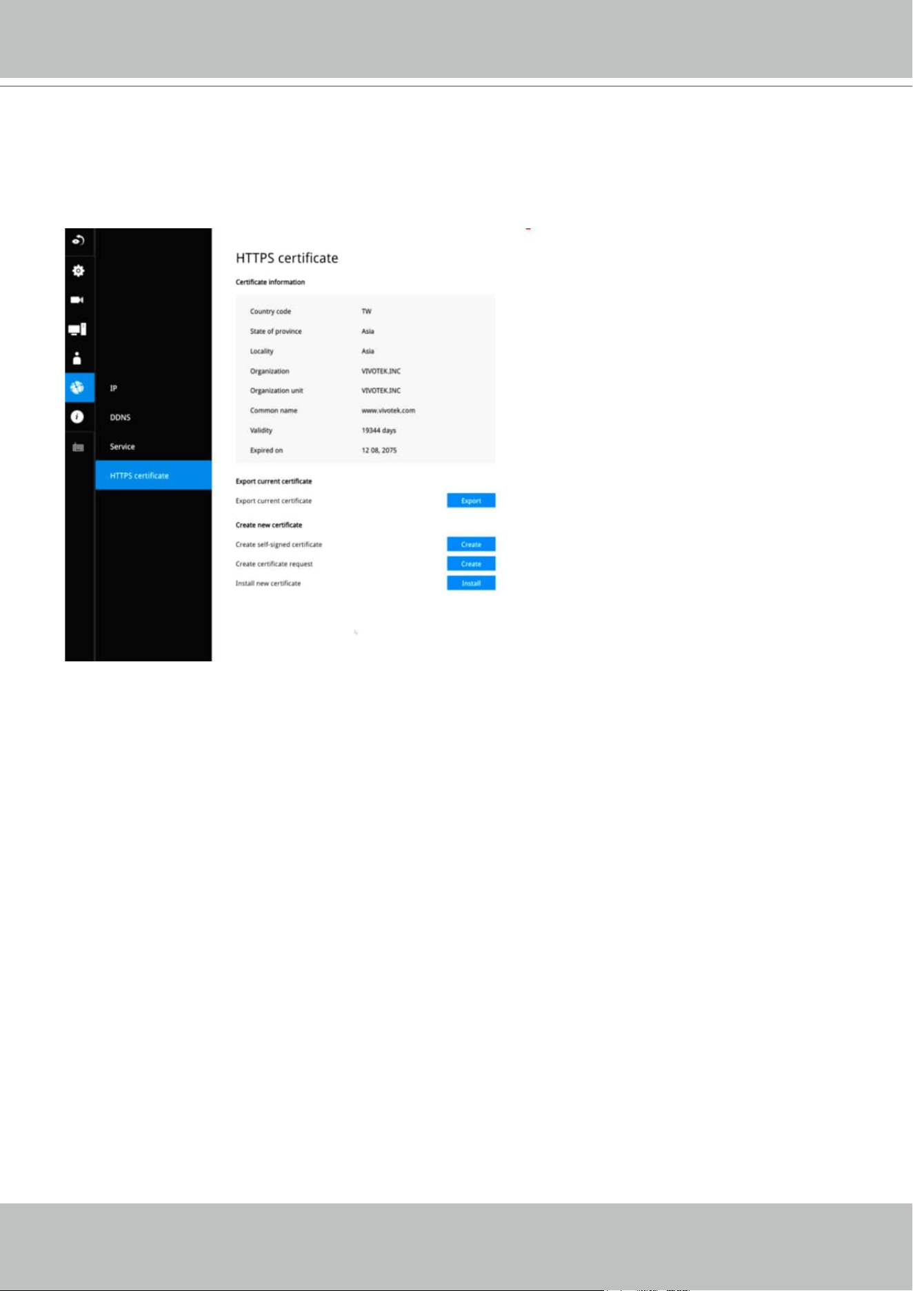
3-6. HTTPS certicate
This window allows the export, import, and to create an HTTPS certicate for secure connection
to the receiver.
VIVOTEK - Built with Reliability
62 - User's Manual
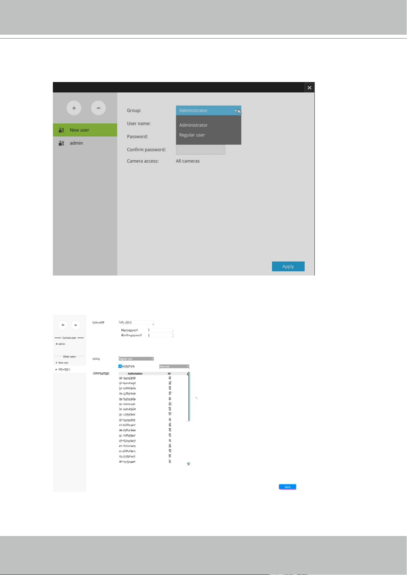
3-7. User
The User window allows you to create more users, to change user password, and place
limitations on users' privileges and administration rights. Up to 16 users can be created,
including the default administrator.
1. By default, there are two user groups: Administrator and Regular user.
2. The regular users cannot access the Settings window, meaning that regular users can not
add or remove cameras, make changes to alarm, network, and all other system settings.
When users try to access the Settings window, the login window prohibits regular users to log
in. There is simply no regular user's name on the login window.
3. The administrator users can access all cameras recruited in the conguration; while the
regular users can be congured to have access to some or all cameras.
4. The system blocks out the video feeds from users who are denied of the access to particular
cameras.
The default administrator name and password are: admin and admin. It is highly recommended
to change the default password to prevent unauthorized access to the system.
IMPORTANT:
VIVOTEK - Built with Reliability
User's Manual - 63
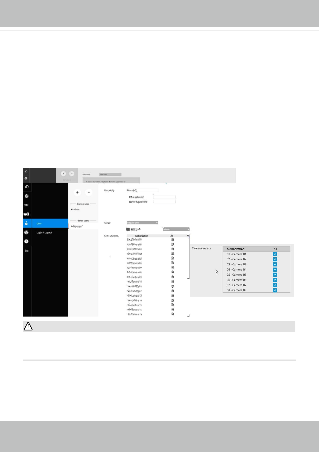
To create or edit users,
1. Select a User group by unfolding its pull-down menu. Select either an Administrator or
regular user as the user group.
2. Enter the User name and password. The max. number of characters for a user name is
64, with alphabetic and numeric characters including [0-9][a-z][A-Z][_][ ][-][.][,][@]. The
max. number for password is also 64.
VIVOTEK - Built with Reliability
64 - User's Manual
3. If you are creating a regular user with limited access to cameras, deselect the checkboxes by
the cameras to deny the user access.
4. Click Apply to close the conguration window. Repeat the process to create more users.
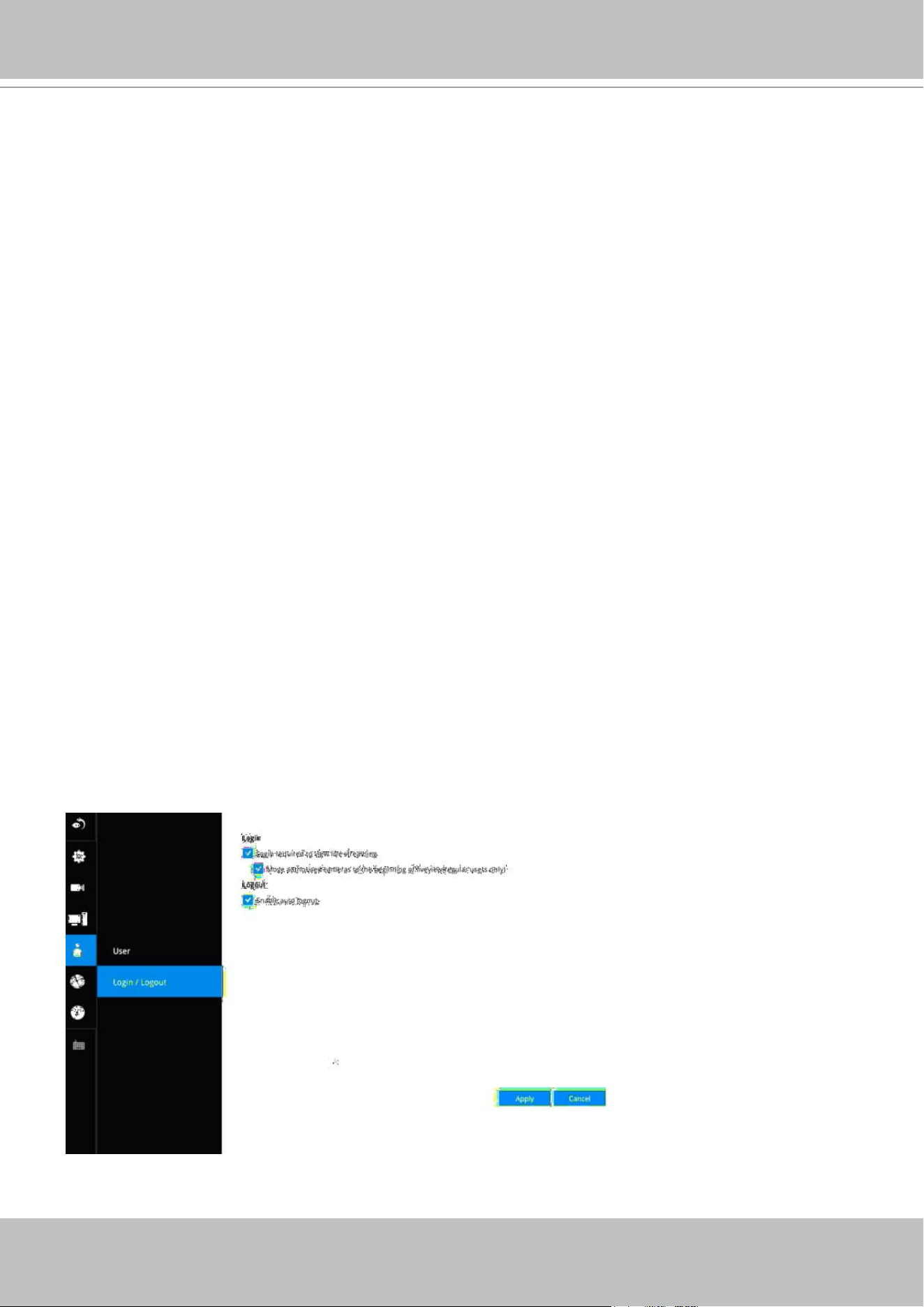
Settings–User-Login / Logout
Logout
1. Enable auto logout: By default, a user is logged out automatically after being idle for 10
minutes. If not selected, the Receiver will not log out automatically. A user can only log out
manually.
Login
1.
Login required to view live streaming: If selected, users will be required to enter his/her
credentials before displaying a live view. If not selected, the Receiver displays live view rst.
Login will be required when performing specic tasks, such as entering the Settings page.
Auto Logout should also be enabled when the Receiver can be left unattended for an
extended period of time. Default is 10 minutes.
Camera views will be available for users according to their privilege settings as designated in
the User account conguration. Some camera views will be available for some users, while
others are not.
2.
Move authorized cameras to the beginning of live view (regular users only): For users who
have access to specic cameras only, he will be required to enter his credentials before
viewing a live view.
VIVOTEK - Built with Reliability
User's Manual - 65
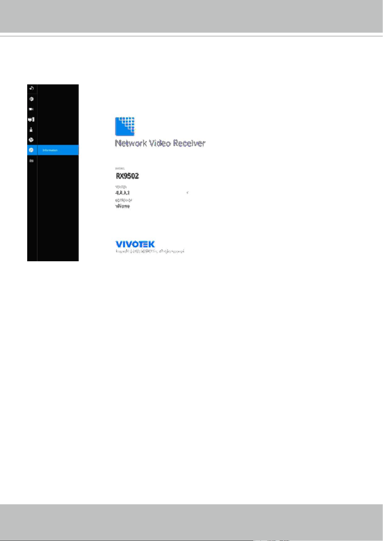
3-8. Information
This window shows the revision number of the rmware running on this machine.
VIVOTEK - Built with Reliability
66 - User's Manual
Section Two
Management over a Web Console
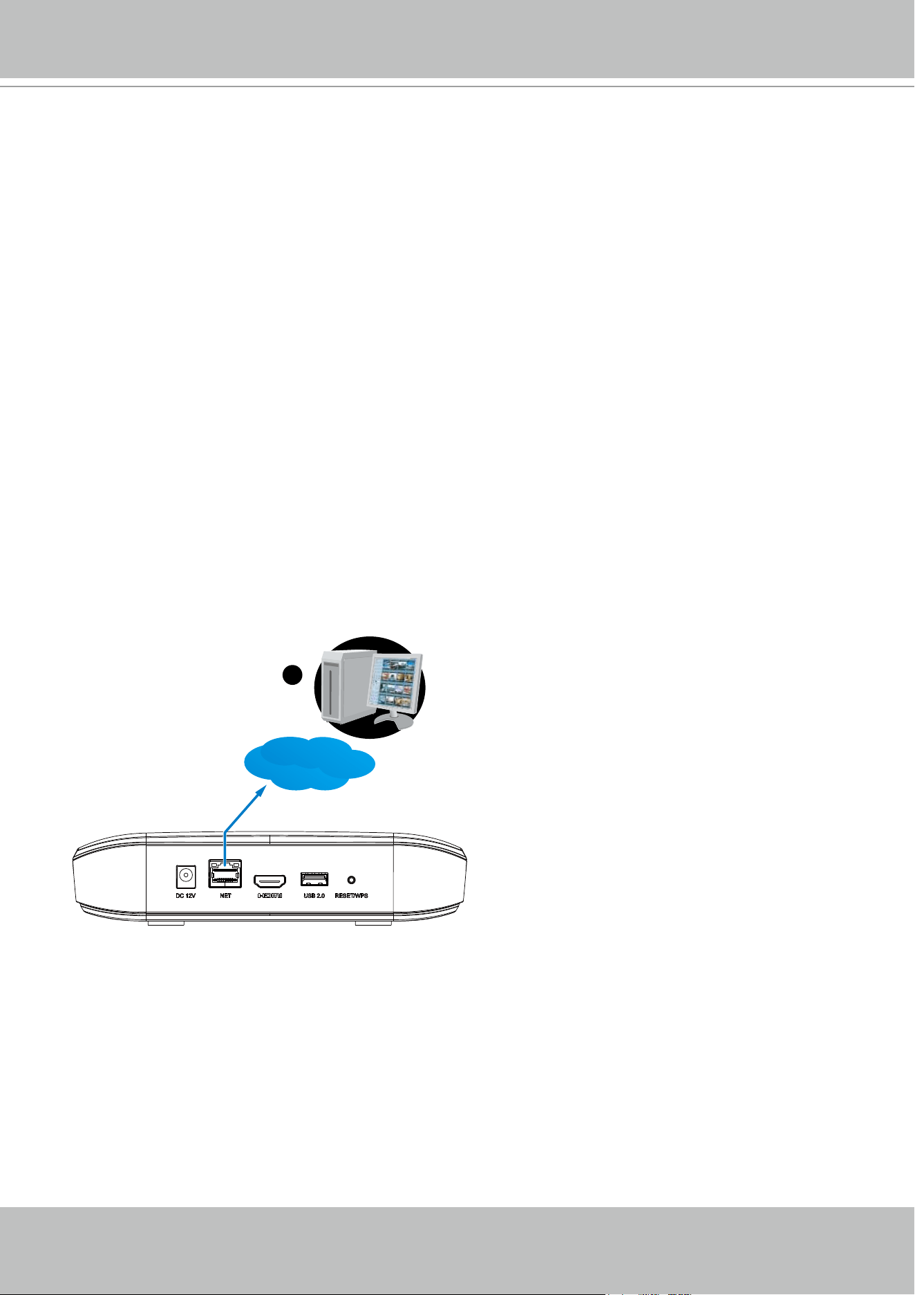
There are two dierent interfaces on the system:
1. One is connecting mouse and keyboard, and an HDMI cable to a TV or monitor. The local
management thus made is described in Section One of this manual.
2. The other is accessed through the Ethernet connection. The management interface via a web
console is identical to the local console. Please refer to the previous discussion for details.
In addition to this, only the Settings page is accessible via the web console. Live view is not
available through the Ethernet connection.
1
Web console
LAN / WAN
Since the Setting pages are identical, the following pages will be omitted. Please refer to page
35 for the description of the same details in System Settings via a local console.
VIVOTEK - Built with Reliability
User's Manual - 67
Some minor dierences between the web console and local console exist. One is the Restore
Factory default function. It is only available on the web console.
On the chassis, you can press the Restore/WPS button for longer than 10 seconds to restore
system defaults.
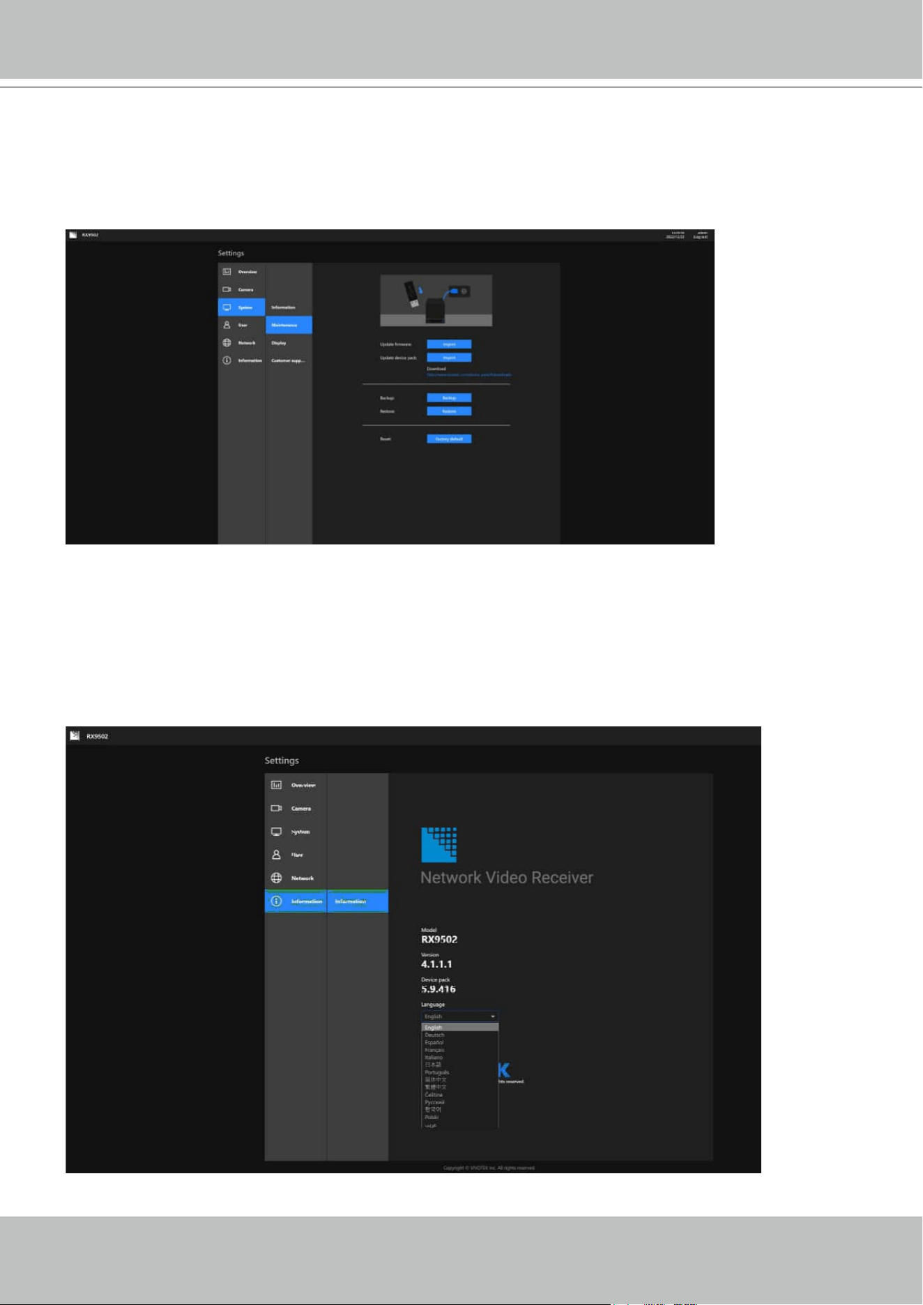
Enter the Information page to change the language used on the conguration interface.
VIVOTEK - Built with Reliability
68 - User's Manual
Another dierence is the ability to enter a system name using languages other than English.
The Receiver's system name also supports the use of other lanaguages. This is only achievable
through a web console.
The following characters are not supported:
[>][<][)][(]["][%][;][#][&][+][-][\]
On the System > Display page, you can congure the display layout, and change the output
resolution. Note that the output resolution is determined by the capability of your TV or monitor.
VIVOTEK - Built with Reliability
User's Manual - 69
Information on Disposal for Users of Waste Electrical & Electronic
Equipment (private households)
This symbol on the products and/or accompanying documents means that used
electrical and electronic products should not bemixed with general household
waste.
For proper treatment, recovery and recycling, please take these products to
designated collection points, where they will beaccepted on a free of charge
basis. Alternatively, in some countries you may be able to return your products to
your local retailerupon the purchase of an equivalent new product.
Disposing of this product correctly will help to save valuable resources and prevent
any potential negative effects on humanhealth and the environment which could
otherwise arise from inappropriate waste handling. Please contact your local
authorityfor further details of your nearest designated collection point.
Penalties may be applicable for incorrect disposal of this waste, in accordance with
national legislation.
For business users in the European Union
If you wish to discard electrical and electronic equipment, please contact your dealer
or supplier for further information.
Information on Disposal in other Countries outside the European Union
This symbol is only valid in the European Union.If you wish to discard this product,
please contact your local authorities or dealer and ask for the correct method of
disposal.
Safety and Compatibility
Federal Communications Commission (FCC) Statement
This Equipment has been tested and found to comply with the limits for a Class A
digital device, pursuant to Part 15 of the FCC rules. These limits are designed to
provide reasonable protection against harmful interference when the equipment is
operated in a commercial environment. This equipment generates, uses and can
radiate radio frequency energy and, if not installed and used in accordance with the
instructions, may cause harmful interference to radio communications. Operation of
this equipment in a residential area is likely to cause harmful interference in which
case the user will be required to correct the interference at his own expense.
Warning:
[A shielded-type power cord is required in order to meet FCC emission limits and also
to prevent interference to the nearby radio and television reception. It is essential that
only the supplied power cord be used. ]
[Use only shielded cables to connect I/O devices to this equipment.]
You are cautioned that changes or modications not expressly approved by the party
responsible for compliance could void your authority to operate the equipment.
[ ]: depend on EUT condition.
VIVOTEK - Built with Reliability
70 - User's Manual
Japan VCCI Class A statement
ACA (Australian Communications Authority)
CAUTION
RISK OF EXPLOSION IF BATTERY IS REPLACED
BY AN INCORRECT TYPE.
DISPOSE OF USED BATTERIES ACCORDING TO THE INSTRUCTIONS