
20V SV20 BRUSHLESS CORDLESS NUT
RIVETER - BODY ONLY
MODEL NO: CP20VNR
Thank you for purchasing a Sealey product. Manufactured to a high standard, this product will, if used according to these
instructions, and properly maintained, give you years of trouble free performance.
IMPORTANT: PLEASE READ THESE INSTRUCTIONS CAREFULLY. NOTE THE SAFE OPERATIONAL REQUIREMENTS, WARNINGS & CAUTIONS. USE
THE PRODUCT CORRECTLY AND WITH CARE FOR THE PURPOSE FOR WHICH IT IS INTENDED. FAILURE TO DO SO MAY CAUSE DAMAGE AND/OR
PERSONAL INJURY AND WILL INVALIDATE THE WARRANTY. KEEP THESE INSTRUCTIONS SAFE FOR FUTURE USE.
CP20VNR Issue 1 21/11/23
Original Language Version
© Jack Sealey Limited
Refer to
instructions
Wear eye
protection
Wear ear
protection
Wear safety
footwear
1. SAFETY
1.1. GENERAL SAFETY
9 WARNING!- Read all safety warnings, instructions, illustrations and specications provided with this power tool. Failure to follow all
instructions listed below may result in electric shock, re and/or serious injury.
9 Save all warning and instructions for future reference.
9 Keep work area clean and well lit. Cluttered or dark area invites accidents.
8 DO NOT operate power tools in explosive atmospheres, such as in the presence of ammable liquids, gases or dust. Power tools
create sparks which may ignite the dust or fumes.
9 Keep children, bystanders and pets away whilst operating a power tool. Distractions can cause you to lose control.
9 Stay alert, watch what you are doing and use common sense when operating a power tool.
8 DO NOT use a power tool whilst you are tired or under the inuence of drugs, alcohol, or medication. A moment inattention whilst
operating power tools may result in serious injury.
9 Use personal protective equipment. Always wear eye protection. Protective equipment such as dust mask, non-skid safety shoes,
hard hat or hearing protection use for appropriate conditions will reduce personal injuries.
9 Prevent unintentional starting. Ensure the switch is in the o position before connecting to power source and/or battery pack,
picking up or carrying the tool. Carrying power tools with your ngers on the switch or energising power tools that have the switch
on invites accidents.
9 Remove any adjusting key or wrench before turning the power tool on. A wrench or a key left attached to a rotating part of the
power tool may result in personal injury.
9 Remove battery pack from the tool before making any adjustments, changing accessories, or storing power tools.
8 DO NOT overreach. Keep proper footing and balance at all times. This enables better control of the power tool in unexpected
situations.
8 DO NOT wear loose clothing, jewellery and dress properly. Keep your hair and clothing away from moving parts. Loose clothes,
jewellery or long hair can be caught in moving parts.
8 DO NOT let familiarity gained from frequent use of tools allow you to become complacent and ignore tool safety principles. A
careless action can cause severe injury within a fraction of a second.
8 DO NOT force the power tool. Use the correct power tool for your application. The correct power tool will do the job better and safer
at the rate for which it was designed.
8 DO NOT use the power tool if the switch does not turn it on and o. Any power tool that cannot be controlled with the switch is
dangerous and must be repaired.
9 Store idle power tools out of the reach of children and DO NOT allow persons unfamiliar with these power tools or these
instructions to operate the power tool. Power tools are dangerous in the hands of untrained users.
9 Maintain power tools and accessories. Have your power tool serviced by a qualied repair person using only identical replacement
parts. This will ensure the safety of the power tool is maintained. Check for misalignment or biding of the moving parts, breakage of
parts and any other condition that may aect the power tool’s operation. If damaged, have the power tool repaired before use.
9 Many accidents are caused by poorly maintained power tools.
9 Use the power tool, accessories and tool bits etc, in accordance with these instructions, taking into account the working conditions
and the work to be performed. Use of the power tool for operations dierent from those intended could results in a hazardous
situation.
9 Keep handles and grasping surfaces dry, clean and free from oil and grease. Slippery handles and grasping surfaces DO NOT
allow for safe handling and control of the tool in unexpected situation.
9 Hold the power tool by insulated gripping surfaces, when performing an operation where the fastener may contact hidden wiring.
Fasteners contacting a “live” wire may make exposed metal parts of the power tool “live” and could give the operator
an electric shock
9 Avoid body contact with earthed or grounded surfaces, such as pipes, radiators, ranges and refrigerators. There is an increased
risk of electric shock if your body is earthed or grounded.
8 DO NOT expose power tools to rain or wet conditions. Water entering a power tool will increase the risk of electric shock.
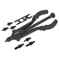
2. INTRODUCTION
Suitable for aluminium rivet nuts with a pulling force of up to 4000N. Three selectable power settings to help preserve the battery by only
supplying the force required. Quick release mechanism which allows for speedy mandrel changes. LED battery level indicator. Supplied with
seven sets of threaded mandrels from M3 to M12 and fast charge mains charger. Requires compatible 20V battery and mains charger, sold
separately.
3. SPECIFICATION
Battery: ..................20V 2Ah - 6Ah Lithium-ion (not included)
Blind Rivet Type: ................................................... Aluminium
Consumable Parts: CP20VBP2 - 2Ah Battery, CP20VBP4 - 4Ah Battery, CP20VBP6 - 6Ah Battery
Maximum Pulling Force: ...............................................4000N
Nozzle Size(s): .....................M3, M4, M5, M6, M8, M10, M12
4. OPERATION
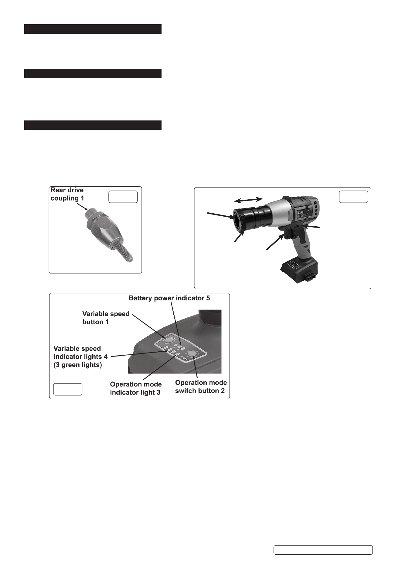
4.1. ATTACHING A THREADED MANDREL
4.1.1. Select correct size threaded mandrel required to suit nut rivet.
4.1.2. Remove rear drive coupling (g 1 - 1) from threaded mandrel (g 2 - 2) and secure onto hexagon drive shaft inside the quick release
mechanism (g 2 - 1).
4.1.3. Pull back the quick release mechanism (g 2 - 1) and insert the threaded mandrel into the quick release mechanism ensuring that it
locates onto the rear drive coupling.
4.1.4. Release the quick release mechanism to lock threaded mandrel in place.
4.2. REMOVING THE THREADED MANDREL
4.2.1. Pull back the quick release mechanism (g 2 - 1) and remove the threaded mandrel and rear drive coupling (g 1 - 1).
4.2.2. Release the quick release mechanism.
4.3. USING THE NUT RIVETING GUN
The nut riveter has two modes: Manual Operation and Intelligent Automatic Operation.
NOTE: The nut riveting gun is suitable for ALUMINIUM rivet nuts only. Using the nut riveting gun with nut inserts other than
aluminium nut inserts, will damage the threaded mandrel and invalidate the warranty.
NOTE: Prior to using the nut riveter, it may be practical to practise using the nut riveter on a test piece.
WARNING! Ensure that the direction switch (g 2 - 4) is fully pushed through from the right side (direction arrow pointing towards
quick release mechanism) to left side. If the direction switch is pushed in the other direction the nut riveting function will not operate.
4.4. MANUAL OPERATION MODE
4.4.1. Press the operation mode switch button (g 3- 2) and the operation mode indicator light (g 3 - 3) will turn on permanently.
4.4.2. Pull the trigger (g 2 - 3) and the nut riveting will begin.
4.4.3. When the nut riveting process is complete, release the trigger and the threaded mandrel (g 3 - 2) will reverse out of the nut insert.
NOTE: The time required to complete the nut riveting is determined by the thickness of the riveted material and size of the nut insert.
4.5. INTELLIGENT AUTOMATIC OPERATION MODE
This operation can be used when there is a quantity of nut riveting to be completed on the same material thickness and nut inserts.
4.5.1. Complete the rst nut riveting operation as detailed in section 4.7.
4.5.2. Press the operation mode switch button (g 3- 2) and the operation mode indicator light (g 3 - 3) will ash.
4.5.3. The nut riveter will retain the last nut riveting settings.
g.2
Quick Release
Mechanism - 1
Direction
Switch - 4
Trigger - 3
Threaded
Mandrel
Location
2
g.1
g.3
Original Language Version
© Jack Sealey Limited
CP20VNR Issue 1 21/11/23

Original Language Version
© Jack Sealey Limited
4.5.4. For the remaining nut inserts, pull the trigger (g 3 - 3) and the nut riveting operation will complete automatically.
4.5.5. To switch back to manual operation mode press the operation mode switch button (g 3 - 2) and the operation mode indicator light
(g 3 - 3) will turn on permanently.
4.6. VARIABLE SPEED OPERATION
4.6.1. To select the speed required press the variable speed button (g 3 -1) once for low speed (one green light), twice for mid speed
(two green lights) and three times for maximum speed (three green lights).
NOTE: Variable speed is not available if nut riveter is in automatic operation mode.
4.7. TRIGGER OPERATION
4.7.1. The rotational speed can be controlled by the trigger (g 2 - 3). Pull the trigger slightly for low rotational speed. To increase the
speed pull further on the trigger.
4.8. BATTERY POWER INDICATOR
4.9. When all the battery indicator lights (g 3 - 5) are on, the battery is at full charge.
5. MAINTENANCE
WARNING: Ensure battery is removed before performing any maintenance or making adjustments, changing accessories, or storing
power tools. Such preventive safety measures reduce the risk of starting the power tool accidentally.
5.1. Have your power tool serviced by a qualied repair person using only identical replacement parts. This will ensure that the safety of
the power tool is maintained.
5.2. Never service damaged battery packs. Service of battery packs should only be performed by the manufacturer or authorised service
providers.
5.3. Use a clean cloth to remove dirt, dust oil, grease etc.
8 DO NOT use solvents to clean the nut riveter.
WARNING! – Risk of Hand Arm Vibration Injury.
This tool may cause Hand Arm Vibration Syndrome if its use is not managed adequately.
This tool is subject to the vibration testing section of the Machinery Directive 2006/42/EC.
This tool is to be operated in accordance with these instructions.
Measured vibration emission value (a): 0.079 m/s²
Uncertainty value (k): 1.5 m/s²
Please note that the application of the tool to a sole specialist task may produce a different average vibration emission. We
recommend that a specific evaluation of the vibration emission is conducted prior to commencing with a specialist task.
A health and safety assessment by the user (or employer) will need to be carried out to determine the suitable duration of use for each
tool.
NB: Stated Vibration Emission values are type-test values and are intended to be typical.
Whilst in use, the actual value will vary considerably from and depend on many factors.
Such factors include; the operator, the task and the inserted tool or consumable.
NB: ensure that the length of leader hoses is sufficient to allow unrestricted use, as this also helps to reduce vibration.
The state of maintenance of the tool itself is also an important factor, a poorly maintained tool will also increase the risk of Hand Arm
Vibration Syndrome.
Health surveillance.
We recommend a programme of health surveillance to detect early symptoms of vibration injury so that management procedures can
be modified accordingly.
Personal protective equipment.
We are not aware of any personal protective equipment (PPE) that provides protection against vibration injury that may result from the
uncontrolled use of this tool. We recommend a sufficient supply of clothing (including gloves) to enable the operator to remain warm
and dry and maintain good blood circulation in fingers etc. Please note that the most effective protection is prevention, please refer to
the Correct Use and Maintenance section in these instructions. Guidance relating to the management of hand arm vibration can be
found on the HSC website www.hse.gov.uk - Hand-Arm Vibration at Work.
The declared vibration total value(s) and the declared noise emission value(s) have been measured in accordance with a standard test
method and may be used for comparing one tool with another.
The declared vibration total values and the declared noise emission values may also be used in a preliminary assessment of exposure.
The vibration and noise emissions during actual use of the power tool can dier from the declared values depending on the ways in
which the tool is used, especially what kind of workpiece is processed.
The need to identify safety measures to protect the operator that are based on an estimation of exposure in the actual condition of use.
CP20VNR Issue 1 21/11/23

Sealey Group, Kempson Way, Suffolk Business Park, Bury St Edmunds, Suffolk. IP32 7AR
01284 757500 sales@sealey.co.uk www.sealey.co.uk
ENVIRONMENT PROTECTION
Recycle unwanted materials instead of disposing of them as waste. All tools, accessories and packaging should be sorted, taken to
a recycling centre and disposed of in a manner which is compatible with the environment. When the product becomes completely
unserviceable and requires disposal, drain any fluids (if applicable) into approved containers and dispose of the product and fluids
according to local regulations.
BATTERY REMOVAL
Under the Waste Batteries and Accumulators Regulations 2009, Jack Sealey Ltd are required to inform potential purchasers of products
containing batteries (as defined within these regulations), that they are registered with Valpak’s registered compliance scheme. Jack
Sealey Ltd’s Batteries Producer Registration Number (BPRN) is BPRN00705.
Note: It is our policy to continually improve products and as such we reserve the right to alter data, specifications and component parts without prior
notice.
Important: No Liability is accepted for incorrect use of this product.
Warranty: Guarantee is 12 months from purchase date, proof of which is required for any claim.
Original Language Version
© Jack Sealey Limited
CP20VNR Issue 1 21/11/23