Loading ...
Loading ...
Loading ...
41-11/32
13+1-3/16
52-11/16
8-7/8
23-5/8
14-9/16
3
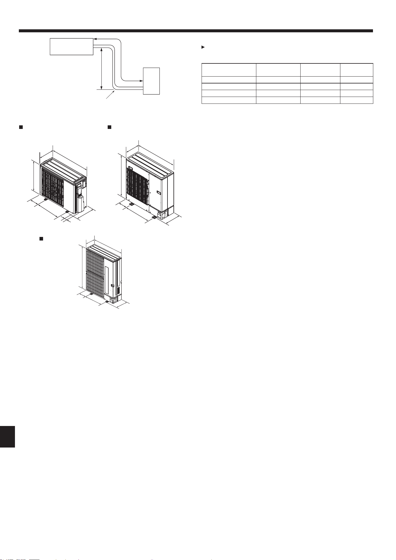
2.1. Refrigerant pipe (Fig. 2-1)
Check that the difference between the heights of the indoor and outdoor
units, the length of refrigerant pipe, and the number of bends in the pipe are
within the limits shown below.
Models
APipe length
(one way)
BHeight
difference
C
Number of
bends (one way)
PUZ-A12, A18 Max. 30 m, 100 ft Max. 30 m, 100 ft Max. 15
PUZ-A24, A30, A36, A42 Max. 50 m, 165 ft *1 Max. 30 m, 100 ft Max. 15
PUY-A12, A18 Max. 50 m, 165 ft Max. 30 m, 100 ft Max. 15
PUY-A24, A30, A36, A42 Max. 69 m, 225 ft *1 Max. 30 m, 100 ft Max. 15
*1. If outdoor unit is connected to the A-COIL indoor unit (PAA-A18, 24, 30, 36, 42),
pipe length is “Max. 30 m, 100 ft”.
• Height difference limitations are binding regardless of which unit, indoor or out-
door, is positioned higher.
D Indoor unit
E Outdoor unit
2.2. Choosing the outdoor unit installation location
• Avoid locations exposed to direct sunlight or other sources of heat.
• Select a location from which noise emitted by the unit will not inconvenience neigh-
bors.
• Select a location permitting easy wiring and pipe access to the power source and
indoor unit.
• Avoid locations where combustible gases may leak, be produced, ow, or accumu-
late.
• Note that water may drain from the unit during operation.
• Select a level location that can bear the weight and vibration of the unit.
• Avoid locations where the unit can be covered by snow. In areas where heavy
snow fall is anticipated, special precautions such as raising the installation location
or installing a hood on the air intake must be taken to prevent the snow from block-
ing the air intake or blowing directly against it. This can reduce the airow and a
malfunction may result.
• Avoid locations exposed to oil, steam, or sulfuric gas.
• Use the transportation handles of the outdoor unit to transport the unit. If the unit is
carried from the bottom, hands or ngers may be pinched.
2.3. Outline dimensions (Outdoor unit) (Fig. 2-2)
Fig. 2-1
A
B
E
D
C
Fig. 2-2
31-7/8
11-13/16+29/32
24-13/16
6-3/32
19-11/16
2-15/32
13
37 -13/32
13+1-3/16
37-1/8
6- 7/8
23-5/8
14-9/16
A12, A18
A36, A42
(inch)
(inch)
(inch)
A24, A30
2. Installation location
en
BG79U896H14_01en.indd 3 2021/10/22 15:52:13
004
Loading ...
Loading ...
Loading ...