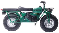
OWNER’S MANUAL
INCLUDES ILLUSTRATED PARTS GUIDE
Copyright 2019 Rokon International Inc. Printed in the U.S.A. ROKON and its logo are
registered trademarks.
Rev 8
2
©2019 Rokon International Inc. Printed in U.S.A. ROKON® and its logo are registered trademarks
INTRODUCTION
Thank you for choosing ROKON. Welcome to the fun and exciting world of 2x2 all terrain
motorcycles! For over 60 years ROKON has been producing the world’s most capable off road
vehicle. Now it’s your turn to feel the adventure and independence that can exclusively be
found on the only “true” all-terrain vehicle on planet Earth! This manual will familiarize you
with operation of your new ROKON. It also contains periodic maintenance procedures and a
comprehensive troubleshooting guide. Enclosed you will also find important safety information,
warranty information and a detailed parts guide that can be used to identify and order
replacement components.
Congratulations on your purchase! By studying this manual and following the procedures
outlined within you will be rewarded with years of reliable service and exceptional Go-
Anywhere performance that thousands of owners have already come to enjoy!
THIS MANUAL SHOULD REMAIN WITH THE VEHICLE IF IT IS SOLD OR TRANSFERRED
3
©2019 Rokon International Inc. Printed in U.S.A. ROKON® and its logo are registered trademarks
IMPORTANT HEALTH AND SAFETY INFORMATION
-The engine exhaust from this product contains chemicals known to the state of California to
cause cancer, birth defects or other reproductive harm.
-Exhaust fumes are poisonous and can cause loss of consciousness and death within a short
time. Always operate your machine in an area with adequate ventilation. DO NOT operate
indoors.
-Gasoline and gasoline vapor is flammable and should always be handled with extreme care.
Avoid areas of open flame or where other potentially high heat sources may exist when
handling gasoline. Avoid inhaling gasoline vapor. If swallowed do not induce vomiting, seek
immediate medical attention. If inhaled remove yourself to an area of fresh air. Seek medical
attention if dizziness, headache, nausea or trouble breathing occur. Avoid contact with the
skin. If skin contact is suspected wash effected area thoroughly with soap and water
immediately. Seek medical attention if a rash or blister develops. Avoid eye contact, if eye
contact is suspected flush with plenty of cold water. Seek medical attention immediately. If
your clothes become contaminated with gasoline, change your clothes as soon as possible
and store contaminated garments away from open flame or other heat sources until they can
be cleaned.
-Ensure that all equipment is properly grounded prior to handling gasoline containers. Avoid
static discharge from the body by touching a metal structure or known ground location.

4
©2019 Rokon International Inc. Printed in U.S.A. ROKON® and its logo are registered trademarks
HOW TO USE THIS MANUAL
FAILURE TO PROPERLY FOLLOW THE INSTRUCTIONS AND WARNINGS OUTLINED IN THIS
MANUAL CAN RESULT IN SERIOUS INJURY OR DEATH
Important or particularly notable information contained within this manual are distinguished by
the following notations:
ALERT – Notifies you of potential injury hazards, obey messages that follow this notation to
avoid possible injury or death.
WARNING – Indicates a hazardous situation which if not avoided will result in serious injury or
death.
NOTICE – Indicates cautions that should be taken to avoid damage to the machine or other
property.
TIP – Provides information that can make a procedure easier.
IMPORTANT NOTICES
The laws regarding proper operation of your ROKON will differ depending on the model you
have purchased as well as which state you reside in.
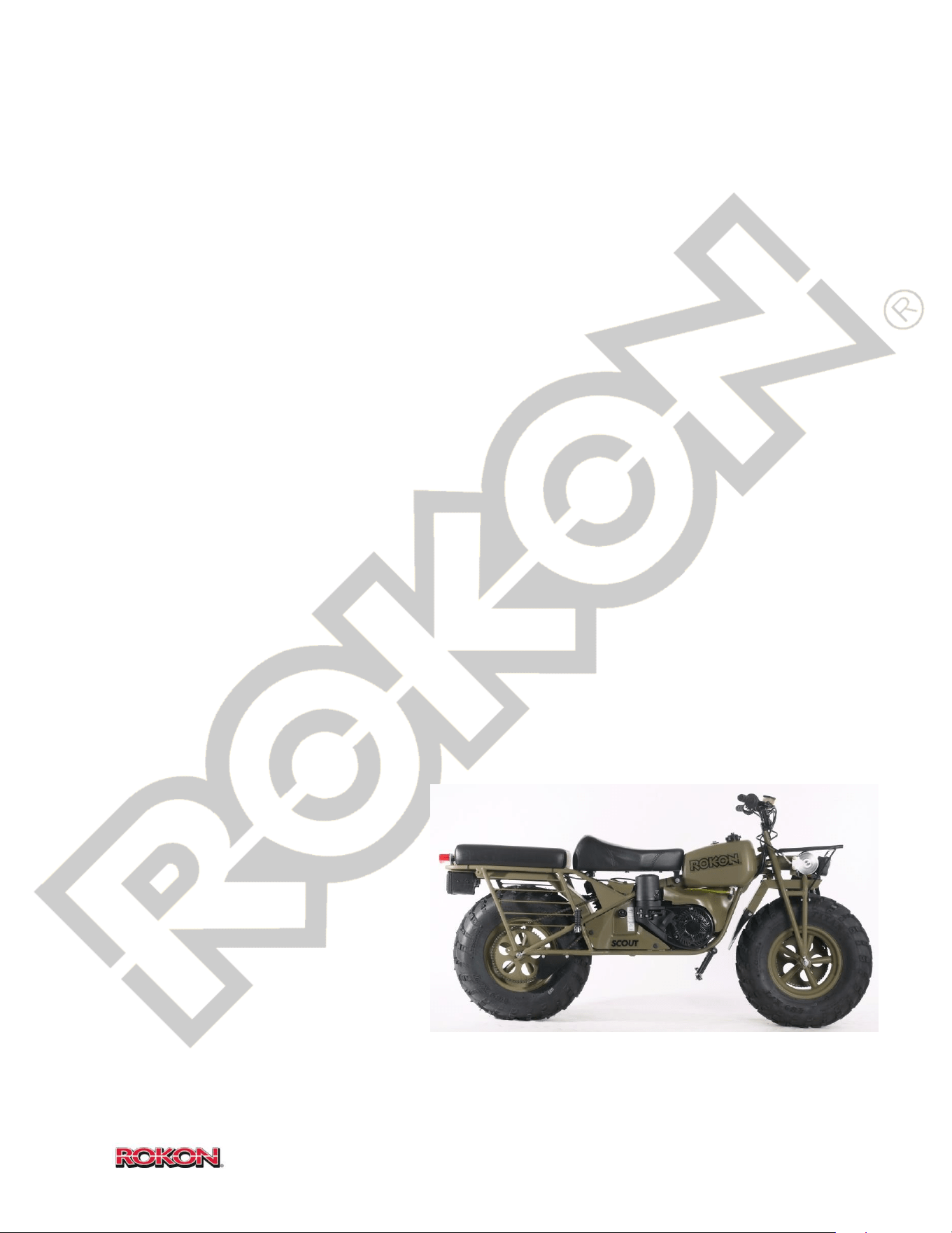
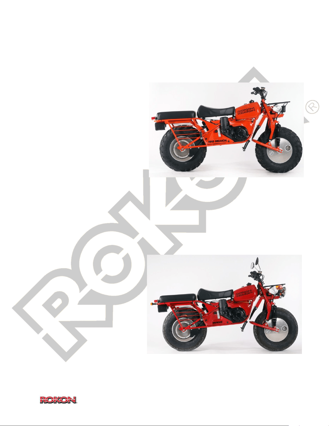
ROKON Scout and Trail-Breaker are designated for OFF ROAD USE ONLY and should never be
operated on any public roadway.
ROKON Ranger is produced with limited on-road capabilities. Rangers are equipped with street
legal equipment including turn signals, mirrors, horn, and high/low beam headlight. In addition,
RANGER VIN number formats and EPA certifications differ from those found on the Scout and
the Trail-Breaker. More information regarding proper public roadway operation can be found in
the street legal section (section 11).
Check your local riding laws before riding your new ROKON.
This machine complies with all applicable Federal off-road noise level, spark arrestor and EPA
laws and regulations in effect at the time of manufacture. Modifications may void compliance.

5
©2019 Rokon International Inc. Printed in U.S.A. ROKON® and its logo are registered trademarks
TABLE OF CONTENTS
Page#
1. Location of warning and specification labels 6
2. Safety Information 7
3. Description 9
4. Specifications 12
5. Unpacking and assembly 14
6. Instruments and control functions 15
7. Pre-operation checks 20
8. Starting 22
9. Operation 23
10. Fording/Floating 26
11. Street Legal Operation 27
12. Cleaning, storage and transportation 29
13. Removal of access/maintenance panels 31
14. Periodic Maintenance and adjustment chart/instructions 33
15. Troubleshooting Guide 43
16. Component removal/installation guide 57
17. Illustrated parts guide 65
18. Wiring Diagrams 100
19. Warranty information 103
20. Emissions control system information 104
21. Maintenance record/notes
6
©2019 Rokon International Inc. Printed in U.S.A. ROKON® and its logo are registered trademarks
1. LOCATION OF WARNING AND SPECIFICATION LABELS
Locate the following warning and information labels and familiarize yourself with their location.
1. Canadian off-highway vehicle label (Canadian machines only)
2. Oil fill warning
3. VIN label (Vehicle Identification Number) Left side below seat
4. EPA Compliance label (on front fender)
5. Street legal compliance label (Ranger only, on front fender)
6. Canadian off-highway compliance label (Canadian machines only, on front fender)
7. Shifting instructions
8. Engine specifications (includes engine serial number)
Locate and record you ROKON’s identification information. Verify that these numbers match
the VIN and Engine Number as listed on your Manufacturers Statement of Origin. Doing so
makes ordering replacement parts easy and also provides a reference if your vehicle is stolen.
VIN # ________________________________________________________________
ENGINE # ___________________________________________________________

7
©2019 Rokon International Inc. Printed in U.S.A. ROKON® and its logo are registered trademarks
2. SAFETY INFORMATION
A ROKON IS A MOTOR VEHICLE AND CAN BE HAZARDOUS TO OPERATE
A ROKON handles differently from other two wheeled motorcycles, a collision or fall can occur
if you fail to take proper precautions or ride in terrain and conditions that exceed your abilities.
SEVERE INJURY OR DEATH can result if you do not follow these instructions:
- Read this manual and all warning labels.
- Never operate this machine in areas that exceed your capabilities as a rider.
- Children under 16 years of age should not operate this vehicle.
- Do not operate your ROKON on a public roadway or street unless it is designed to do so.
- Never operate a ROKON without wearing an approved motorcycle helmet that properly fits
you. You should also wear boots, eye protection, long pants and a long sleeve shirt.
- Never operate a ROKON under the influence of drugs or alcohol.
- Never operate a ROKON at speeds that exceed your abilities or that are inappropriate for the
terrain you are riding in.
- DO NOT attempt jumps, wheelies, or other stunts.
- Always inspect your ROKON each time you use it to make sure it is in safe operating condition.
- NEVER leave your ROKON in gear when you are not seated on it or when it is unattended.
- Keep both hands on the handlebars at all times during operation, keep feet on foot peg cleats
while moving unless they are required to keep you upright while stationary or moving slowly.
- Ride slowly and use extra caution when operating in unfamiliar terrain.
- Do not operate in excessively rough, loose or slippery conditions until you attain the skills
necessary to control the ROKON in such terrain.
- Never operate the ROKON on hills too steep for the machine or your abilities. Practice on
smaller hills and inclines first.
- ROKON brakes function independently from one another; as such the majority of braking must
be done with the front. Excessive rear braking can result in loss of control. Familiarize yourself
8
©2019 Rokon International Inc. Printed in U.S.A. ROKON® and its logo are registered trademarks
with proper braking pressures to allow reasonable stopping distance without locking/skidding
the rear tire.
- Follow proper procedures for descending hills; never go downhill at high speeds.
- Never operate the ROKON in fast flowing water or in water that exceeds recommended
fording depth. (See section 10)
- Maintain proper tire pressures as described in this manual.
- DO NOT exceed stated load capacities for your ROKON. Always secure cargo prior to riding,
allow for additional braking distance as gross vehicle weight increases.
- Never attempt to change speed ranges while in motion or while the engine is above idle
speed.
- Always make sure your ROKON is in Neutral prior to starting.
- DO NOT attempt to adjust factory settings to idle speed, belt tension/torque converter or
brake system without being advised to by a ROKON factory representative.
- DO NOT refuel your ROKON while it is running or hot from riding.
- Use caution while refueling; avoid spilling fuel on hot exhaust pipes or heat shields.
- Keep your ROKON away from heat sources or open flames while refueling.
- Ground all fueling equipment prior to refueling your ROKON.
9
©2019 Rokon International Inc. Printed in U.S.A. ROKON® and its logo are registered trademarks
3. DESCRIPTION
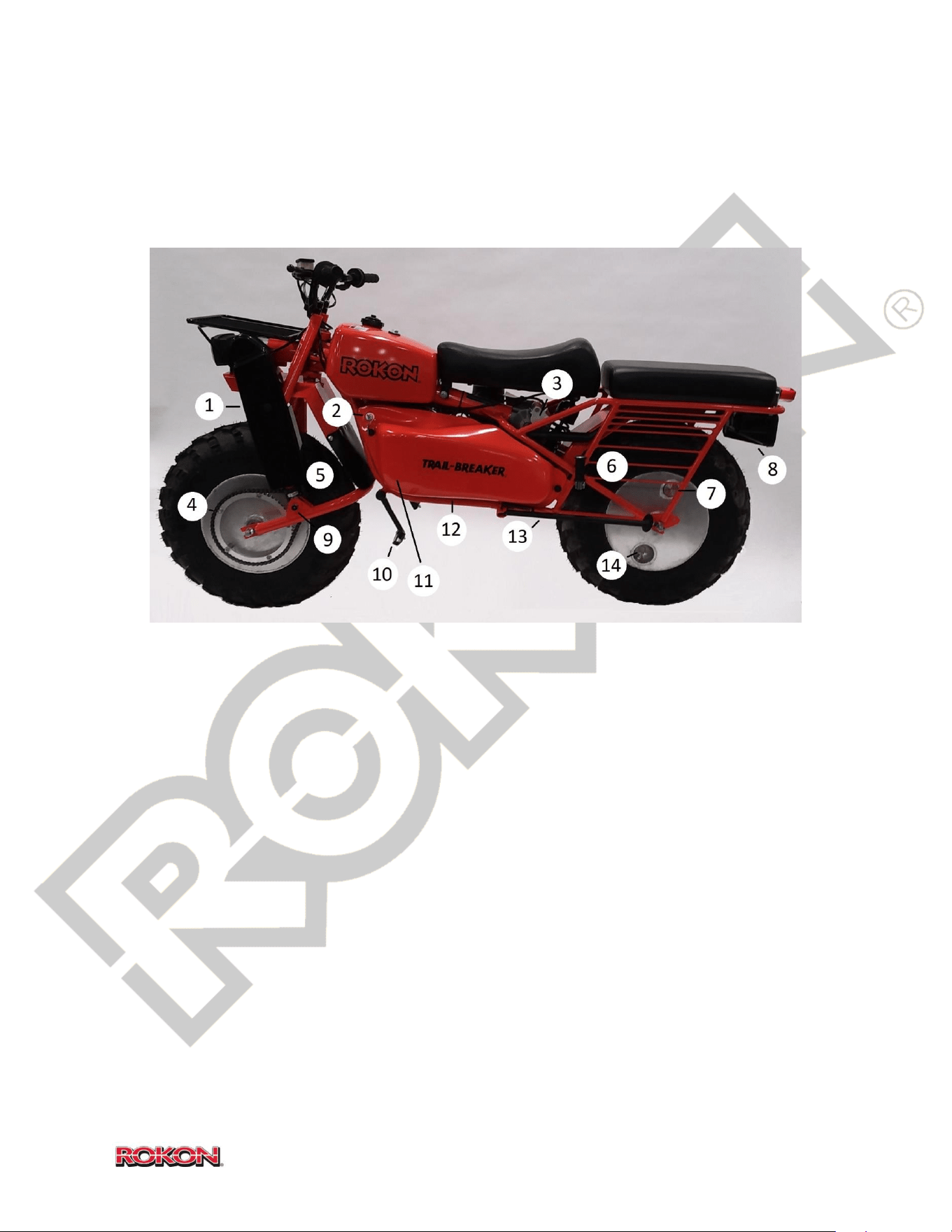
LEFT SIDE
1. Front chain guard
2. Key Switch
3. Rear brake
4. Front Horizontal chain (not
present on scout)
5. Front Vertical chain
6. Passenger foot peg
7. Wheel fill plug
8. Muffler
9. Autograb grease fitting (not
present on Scout)
10. Operator foot peg
11. Oil fill/check plug (beneath
cover)
12. CVT housing cover
13. Kickstand
14. Rear tire air valve
10
©2019 Rokon International Inc. Printed in U.S.A. ROKON® and its logo are registered trademarks
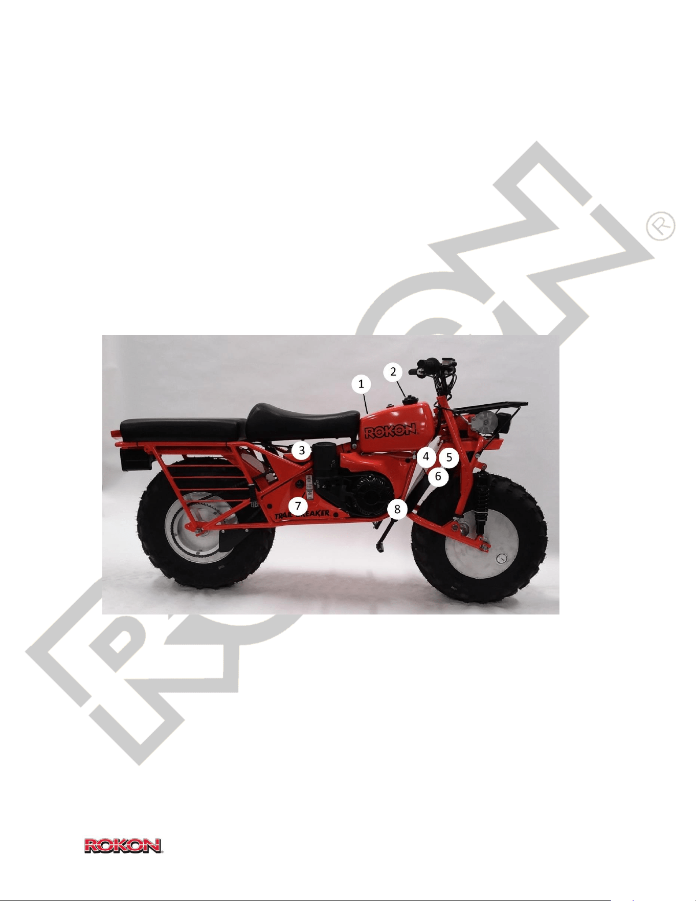
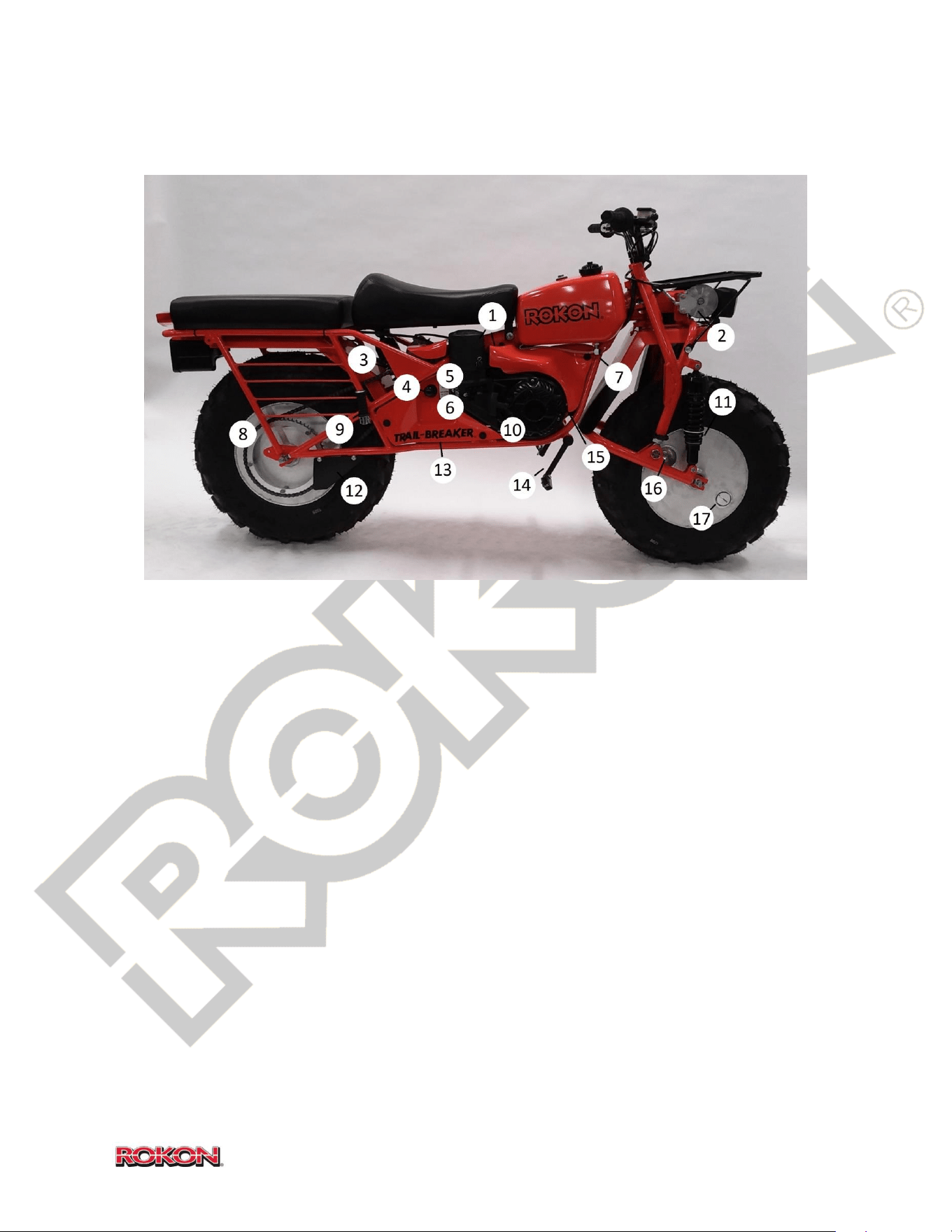
RIGHT SIDE
1. Air cleaner housing
2. Front Brake
3. Seat shock absorber
4. Speed range selector
5. Choke lever
6. Carburetor on-off valve
7. Fuel tank on-off valve
8. Rear chain
9. Passenger foot peg
10. Pull start handle
11. Autograb shock absorber (not
present on Scout)
12. Rear chain guard
13. Battery cover
14. Operator foot peg
15. Fuse holder location
16. Front tire air valve
17. Wheel fill plug
11
©2019 Rokon International Inc. Printed in U.S.A. ROKON® and its logo are registered trademarks
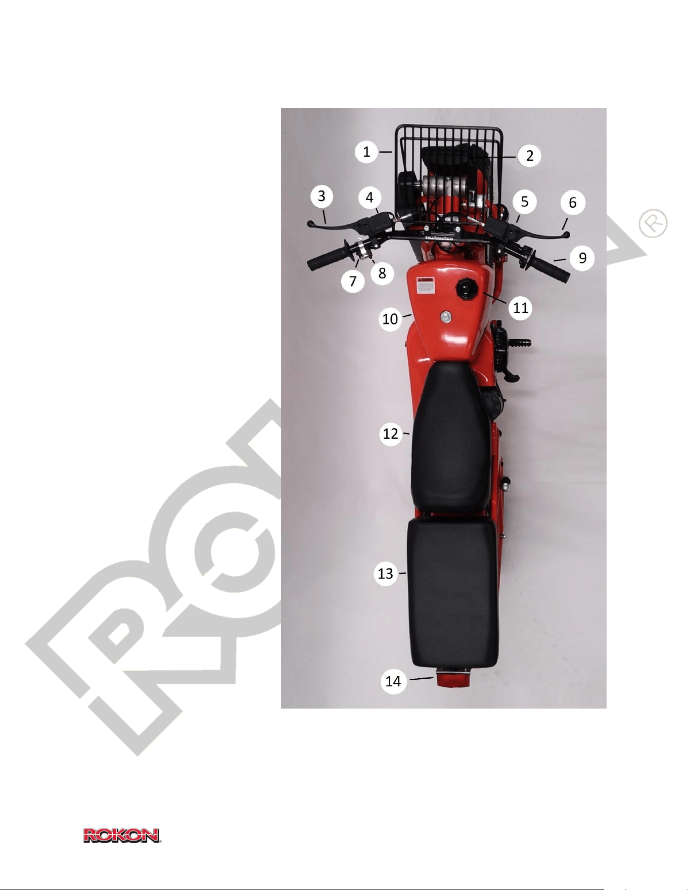
TOP
1. Front cargo rack
2. Headlight
3. Rear brake lever
4. Rear Brake reservoir
5. Front brake reservoir
6. Front brake lever
7. Headlight switch
8. Engine kill button
9. Throttle grip
10. Fuel Tank
11. Fuel fill cap
12. Operator Seat
13. Passenger seat
14. Tail marker/brake
light
12
©2019 Rokon International Inc. Printed in U.S.A. ROKON® and its logo are registered trademarks
4. SPECIFICATIONS
COMMON TO ALL MODELS
Drive System Full time, Front and Rear wheel drive
Engine Kohler, single cylinder, four stroke, air cooled
Displacement 208cc
Power Output 7 HP at 3,600 RPM
Peak Torque 12.4(9.1) Nm(ft. lb.) @ 2800 rpm
Power Transmission Automatic torque converter into a three-gear range selector
Power Take Off 7 HP, speed proportional to throttle setting
Fuel Tank Capacity 2.69 US gal (10.0 L)
Fuel Unleaded gasoline (87 Octane or higher)
Fuel Consumption 0.33 gal/hr (211g/PS h)
Brakes Floating Disc type, hydraulic front and rear
Starter Electric and pull start (automatic recoil with compression release)
Ignition Electronic Magneto
Electrical 12 Volt AGM sealed battery
Exhaust Muffler and U.S. Forestry approved spark arrestor
Carburetor Fixed Main Jet Carburetor (Optional High Altitude Jet Available)
Grade Capability 60 percent
GVWR 600 lbs. (272 kg)
SCOUT
Speed Range 1st gear 0-16 MPH (24 kph) 2nd gear 0-20 MPH (32 kph) 3rd gear 0-32 MPH (51 kph)
Wheels 12 Inch Steel Spoke
Tires 8 x 12 x 25" tubeless set at 7 PSI
Wheel Base 51 Inches (129.5 cm)
Ground Clearance 13 Inches (33 cm)
Height Over Seat 30 Inches (76.2 cm)
Height Over Handlebar 39 Inches (99.1 cm)
Width 30 Inches (76.2 cm)
Length 79 Inches (200.7 cm)
Weight 218 lbs. (98.8 kg)
Fordable Water Depth 20 Inches (50.8 cm)
13
©2019 Rokon International Inc. Printed in U.S.A. ROKON® and its logo are registered trademarks
TRAIL-BREAKER
Speed Range 1st gear 0-16 MPH (24 kph) 2nd gear 0-20 MPH (32 kph) 3rd gear 0-32 MPH (51 kph)
Wheels 12 aluminum drum wheels with 2.69 US gal (10.0 L) fluid capacity
Tires 8 x 12 x 25" tubeless set at 7 PSI
Wheel Base 51 Inches (129.5 cm)
Ground Clearance 15 Inches (38.1 cm)
Height Over Seat 32 Inches (81.3 cm)
Height Over Handlebar 41 Inches (104 cm)
Width 30 Inches (76.2 cm)
Length 79 Inches (200.7 cm)
Weight 218 lbs. (98.8 kg)
Fordable Water Depth 22 Inches (55.9 cm)
Suspension Travel 6 Inches (15.2cm)
RANGER
Speed Range 1st gear 0-18 MPH (29 kph) 2nd gear 0-25 MPH (40 kph) 3rd gear 0-35 MPH (56 kph)
Wheels 12 aluminum drum wheels with 2.69 US gal (10.0 L) fluid capacity
Tires 8 x 12 x 25" tubeless set at 10 PSI
Wheel Base 51 Inches (129.5 cm)
Ground Clearance 15 Inches (38.1 cm)
Height Over Seat 32 Inches (81.3 cm)
Height Over Handlebar 41 Inches (104 cm)
Width 30 Inches (76.2 cm)
Length 79 Inches (200.7 cm)
Weight 222 lbs. (100 kg)
Fordable Water Depth 22 Inches (55.9 cm)
Suspension Travel 6 Inches (15.2 cm)
14
©2019 Rokon International Inc. Printed in U.S.A. ROKON® and its logo are registered trademarks
5. UNPACKING AND ASSEMBLY
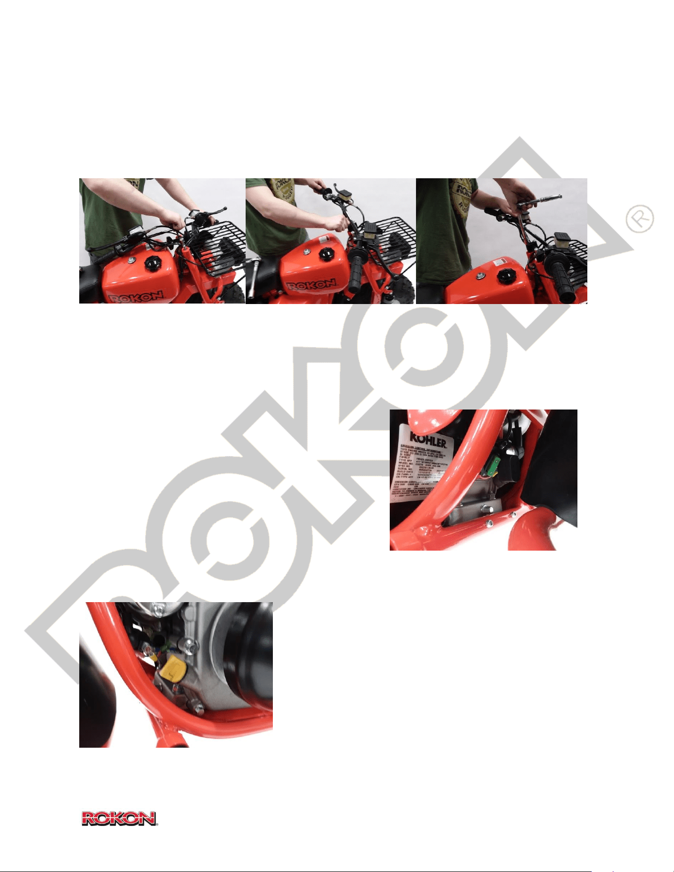
Your ROKON comes almost fully assembled with the exception of the handlebars. They must be
re-attached to the top of the front end. Remove the two 9/16” handlebar bolts that are
threaded into the front end for shipment.
Straighten out the handlebars and align them to the front end. Be sure not to twist the control
cables or hoses in the wrong direction. Using a 9/16” socket or wrench, tighten the handlebar
bolts to secure the handlebars in place. Torque handlebar bolts to 15 – 20 ft.-lbs.
Locate the keys and fuse in your manual packet. Insert the fuse into the rubber inline fuse
holder located beneath the electric starter. Close the lid
to protect the fuse from dirt and moisture. Insert the
key into the ignition switch.
In certain circumstances ROKON may opt to disconnect
the negative battery lead prior to shipment. If this has
been done, simply remove any insulator tape from your
negative battery lead and reattach it to the negative
battery terminal. (8mm wrench or socket required).
Add .6 QT of SAE 10W-30 engine oil to your engine via the
forward fill/check plug. NOTICE There is no oil in the
engine at the time of shipment; you MUST add oil prior to
first startup of the engine.
Check tire pressure; verify a pressure of 7psi for off-road
models and 10-12psi for street legal. Front tire pressure
MUST be set equally to or slightly lower than rear.
15
©2019 Rokon International Inc. Printed in U.S.A. ROKON® and its logo are registered trademarks
6. INSTRUMENTS AND CONTROL FUNCTIONS
FUEL SYSTEM CONTROLS
Fuel Tank shut-off valve – Located on the bottom
right side of the fuel tank. When open (down
position), gasoline is allowed to flow from the fuel
tank to the carburetor. Close this valve when storing
or transporting your ROKON.
Choke lever – Located beneath the air filter housing,
Choke function is used to start a cold engine and
should not be operated while riding. To apply the
choke, push the choke lever to the rear position until
engine starts. Once engine is running the choke can
be turned off by returning the lever to the forward
position.
Carburetor fuel shut-off valve – Located on the right side of the bike below the choke lever.
When open (forward position), gasoline is allowed to flow from the fuel line into the float bowl
of the carburetor. Close this valve when storing or transporting your ROKON.
Throttle – Engine speed is increased by twisting the
throttle grip on the right side of the handlebar
counter-clockwise. When released, engine speed will
return to idle.
16
©2019 Rokon International Inc. Printed in U.S.A. ROKON® and its logo are registered trademarks
BRAKE SYSTEM CONTROLS
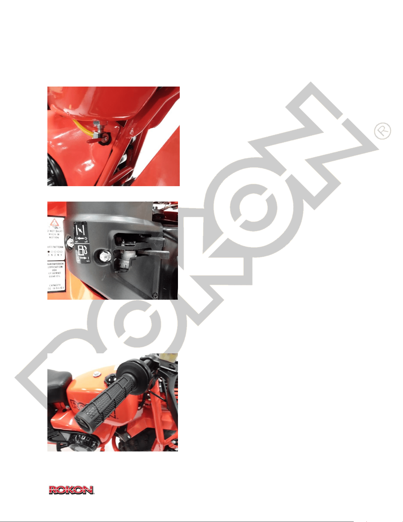
Front Brake – The front brake lever is located on the
right side of the handlebars. When brake pressure is
applied the front brake will slow or stop the entire
driveline. (See Safety Information page 7)
Rear Brake – Located on the left side of the handlebars.
When brake pressure is applied the rear brake slows or
stops the rear tire but allows the front driveline to
rotate independently. (See Safety Information page 7)
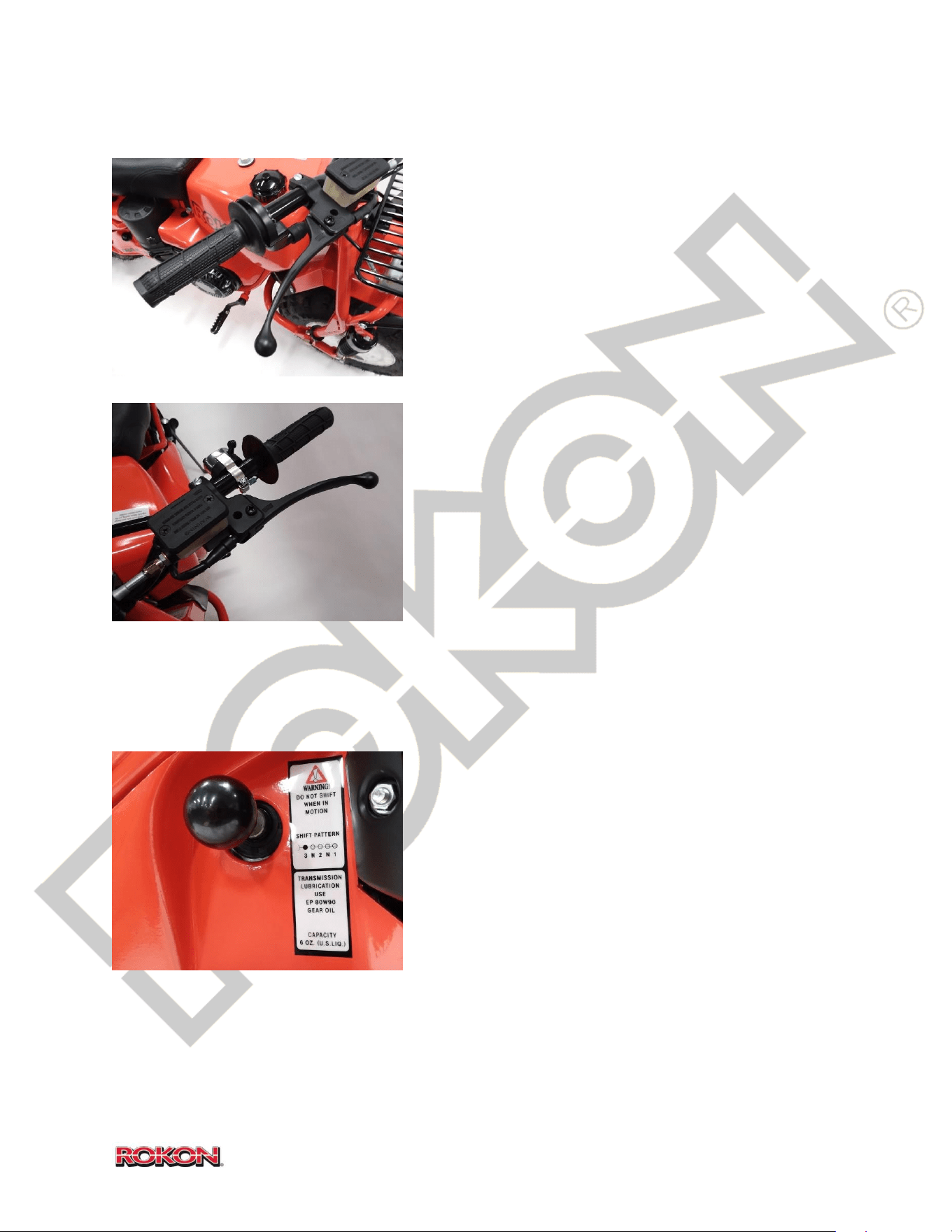
SPEED RANGE CONTROL
Speed range selector knob – Located on the right side
of the bike beneath the right side of the operator seat,
this knob engages the desired speed range and allows
you to select a neutral position. There are five positions
for selecting speed ranges and neutral.
1
st
Gear (low range) Knob is pulled all the way out
Neutral Pos#1 In one position from 1
st
2
nd
Gear (mid-range) Knob is in the middle position or two positions in from 1
st
17
©2019 Rokon International Inc. Printed in U.S.A. ROKON® and its logo are registered trademarks
Neutral Pos#2 In three positions from 1
st
3
rd
Gear (high range) knob is pushed all the way in
NOTICE the bike MUST be motionless and idling normally prior to selecting a speed range.
TIP The knob will sometimes feel stuck when you attempt to select a speed range, if this
happens the gears must be synchronized. In order to do this, it is recommended that you rock
the bike gently back and forth while applying pressure to the selector knob until it slides into
the desired position.
WARNING ALWAYS ensure that your ROKON is in NEUTRAL prior to starting. Failure to do so
can result in unintended movement upon starting.
ELECTRICAL SYSTEM CONTROLS
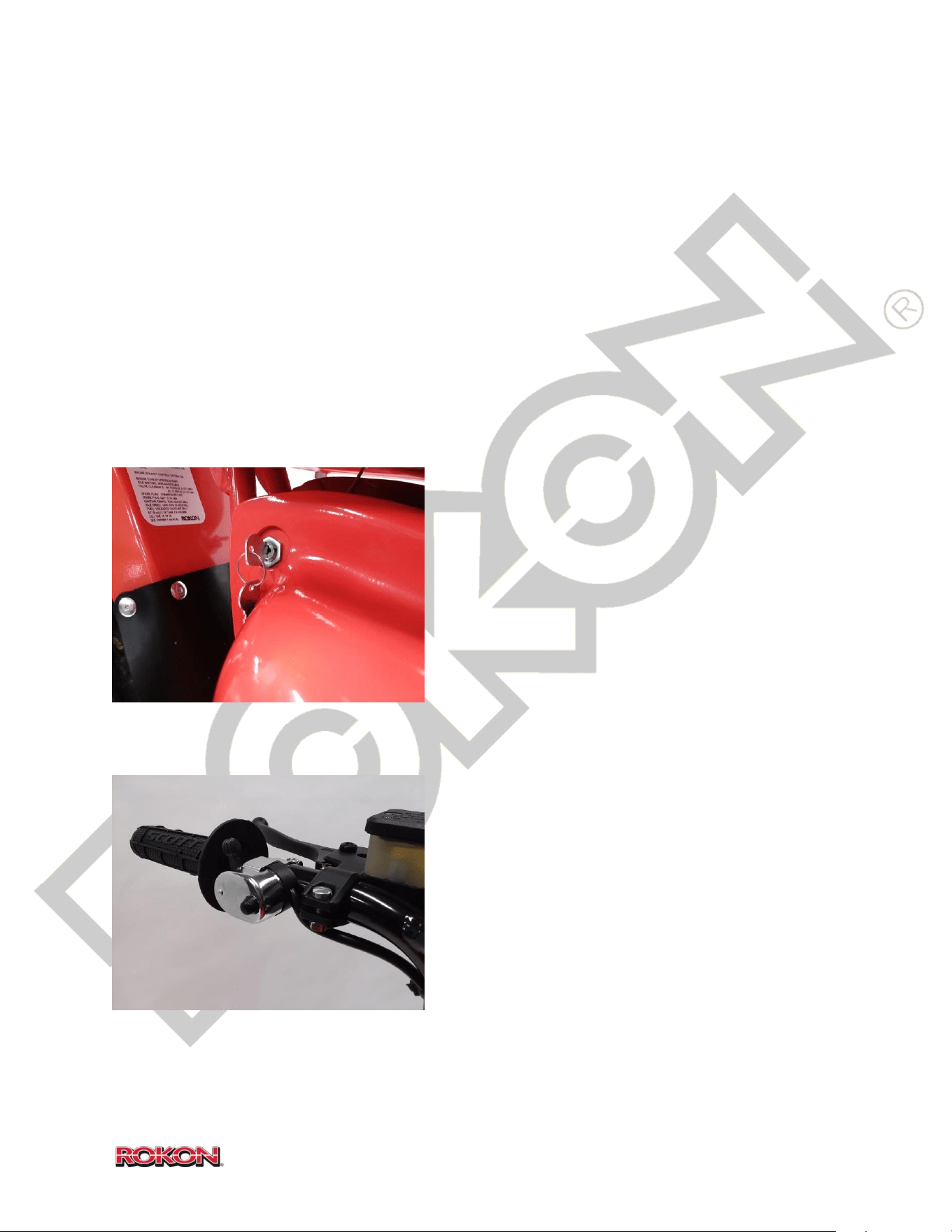
Key switch – The ignition key switch is located
beneath the fuel tank on the left side of the bike. It
has three positions, OFF, RUN, and START. In the OFF
position the kill circuit is grounded and the engine
will not run. The key can be removed from the bike
in this position. In the RUN position, the electrical
system is energized and ignition system is on.
Optional accessories will be energized in this
position. The start position is a momentary position
that engages the electric starter and starts the engine. NOTICE Do not rotate the key to this
position while the engine is running.
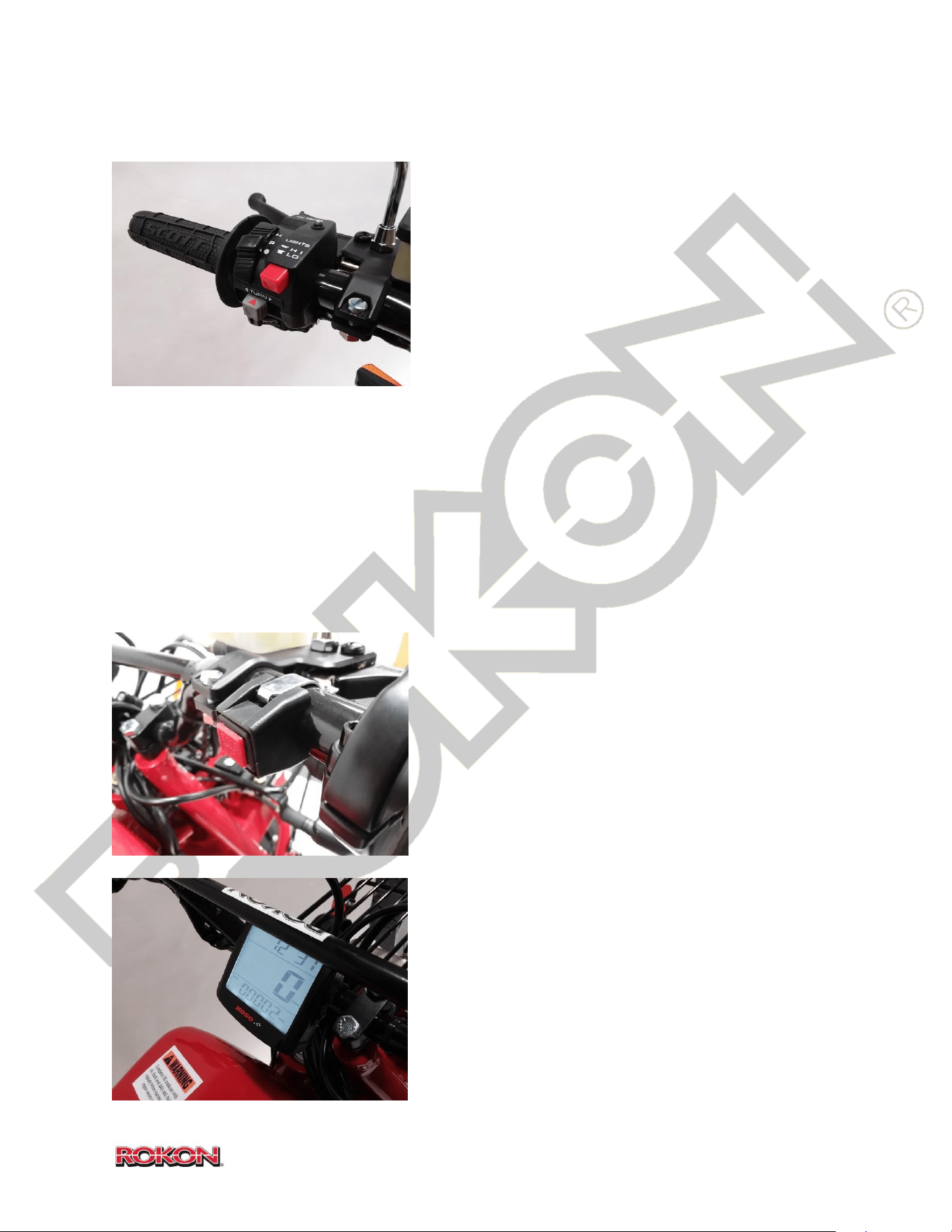
Headlight switch/Kill Button – Located on the left
side of the handlebars, the headlight switch turns
the headlight and rear marker light on and off. There
is also a momentary kill circuit button which can be
used to quickly and easily shut the bike’s engine off.
Hold kill button until engine stops completely.
NOTICE Shutting off the engine in this manner will
not turn off lights or optional accessories. Rotate key
switch to OFF position when you are finished riding
to prevent battery depletion.
Brake light switches – With key switch in the “Run” position, switches illuminate the brake light
when either brake handle is squeezed.
18
©2019 Rokon International Inc. Printed in U.S.A. ROKON® and its logo are registered trademarks
OPTIONAL ELECTRICAL COMPONENTS AND INSTRUMENTS
Street Legal Multifunction Switch – Installed in place
of the headlight switch/kill button on street legal
models, this switch performs multiple tasks.
-Parking lamp selector; P position illuminates rear
marker only, H position illuminates headlight. NOTICE
this switch MUST be in the P or H position in order for
the bike to start and run.
-High/low beam headlight button changes the beam of
the headlight; indicator lamp tells you when high beam is illuminated.
-Horn switch energizes the horn.
-Kill button shuts off the engine, hold kill button until engine stops completely.
-Turn signal operation; push switch to desired direction to illuminate flashing turn signals. Push
switch in to stop signal.
Street Legal right side kill button – Located on the
right side of the handlebars on street legal models, this
momentary switch serves as an extra kill button to
shut off the bike’s engine. Hold kill button until engine
stops completely.
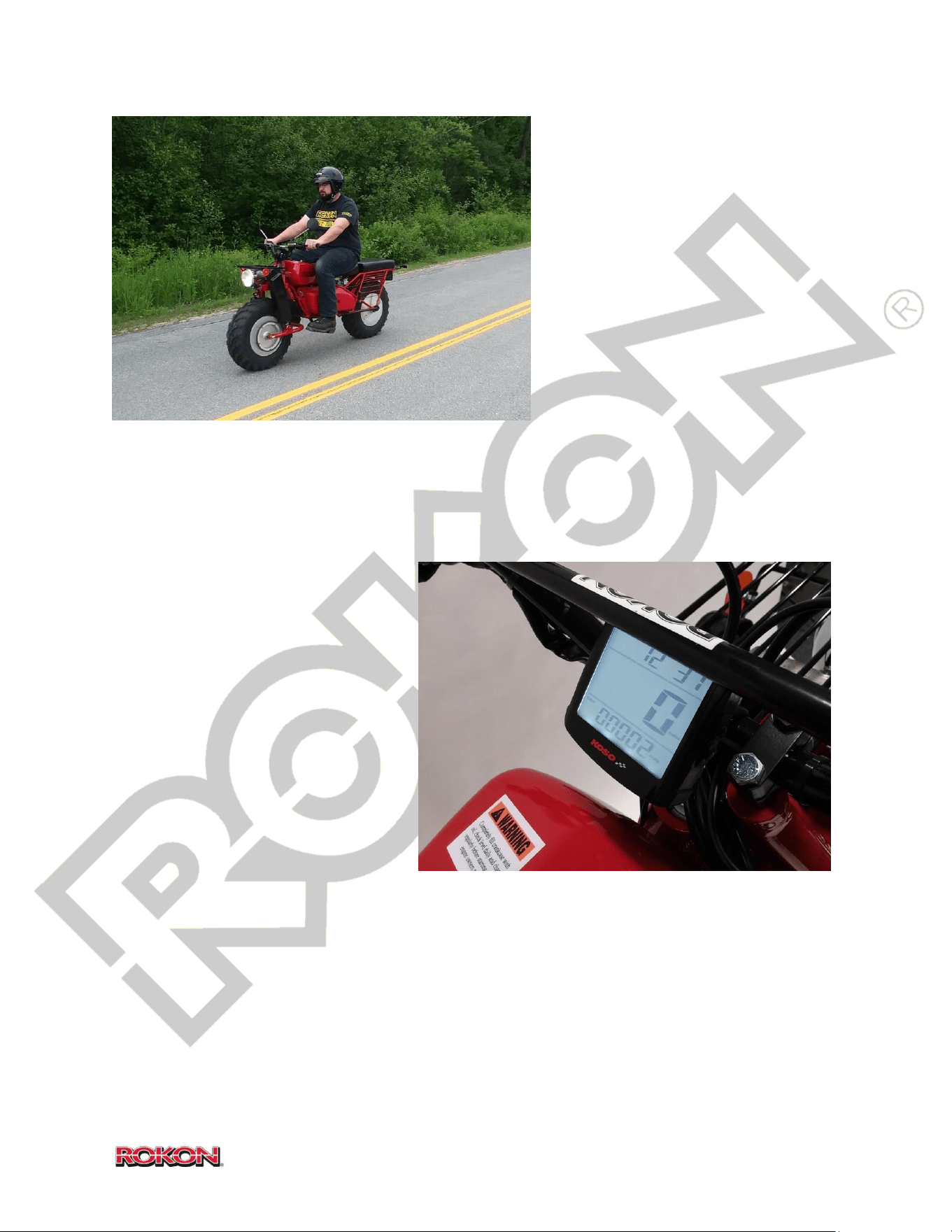
Speedometer – Installed at the center of the
handlebars on street legal models. This unit displays
current speed, distance traveled, time of day and other
information. (See street legal section for further
information regarding the speedometer).
19
©2019 Rokon International Inc. Printed in U.S.A. ROKON® and its logo are registered trademarks
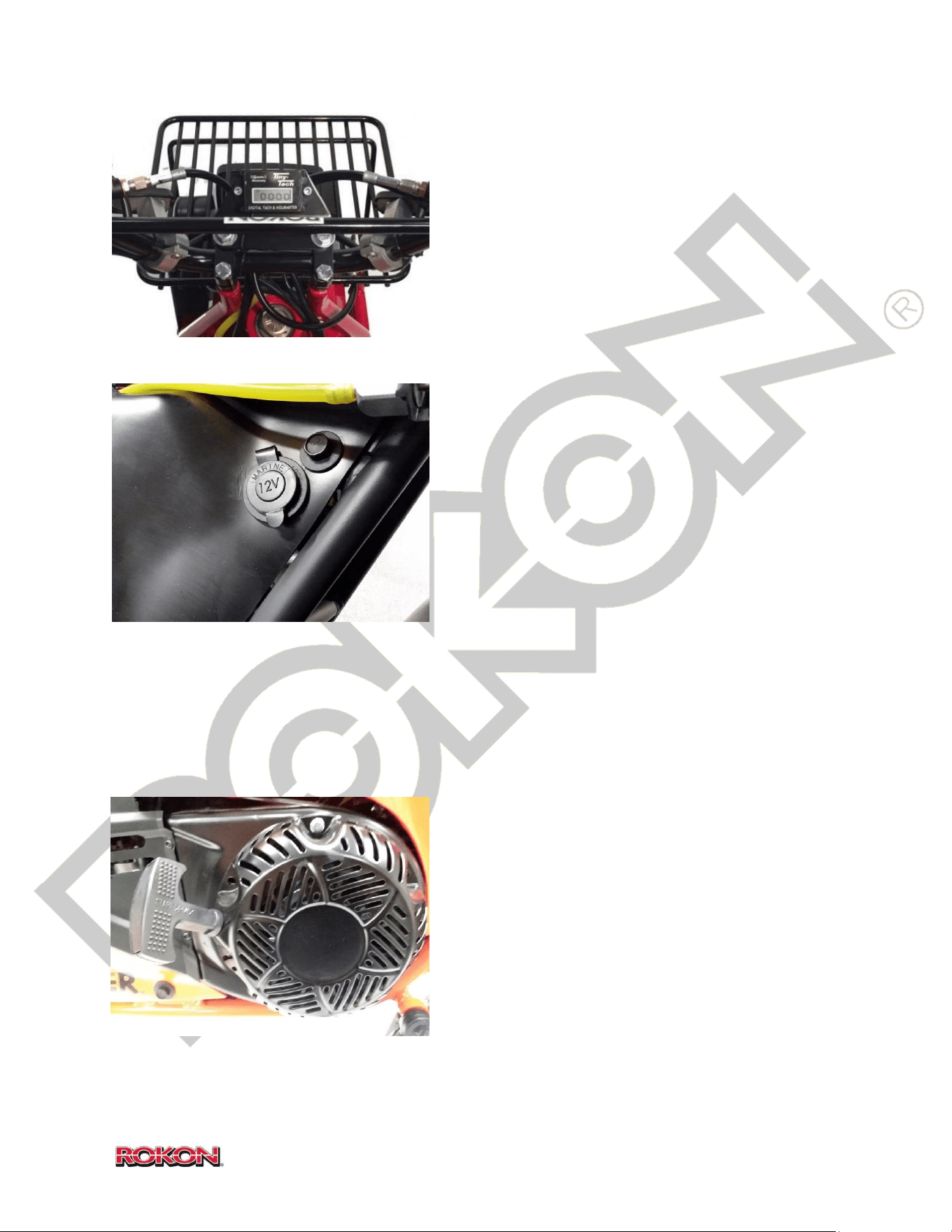
Tach/Hour meter – The optional Tachometer/Hour
meter is installed at the center of the handlebars. It
displays total running hours when the engine is off
and RPMs when the engine is running. This unit
cannot be adjusted or reset.
Power Point – The optional auxiliary DC power
socket is located on the right side of the bike
beneath the fuel tank shut-off valve. It is energized
with the key switch in the “Run” position and can be
used to power accessories such as spot lights,
radios, GPS units and cell phone chargers. (12V DC
10A 120W)
OTHER CONTROLS
Pull starter – In the event that you find your battery
has died or is weak; the pull starter can be used to
start the engine. The engine is equipped with an
automatic compression release to make starting
easy. NOTICE take care not to pull the rope all the
way out while attempting to start the engine.

20
©2019 Rokon International Inc. Printed in U.S.A. ROKON® and its logo are registered trademarks
7. PRE-OPERATION CHECKS
ALERT
FAILURE TO INSPECT YOUR ROKON PRIOR TO OPERATION INCREASES THE POSSIBILITY OF AN
ACCIDENT OR EQUIPMENT DAMAGE. ALWAYS INSPECT YOUR ROKON EACH TIME YOU USE IT
TO ENSURE IT IS IN SAFE OPERATING CONDITION.
Fuel tank – Check fuel level and make sure you have a sufficient amount prior to riding. Inspect
fuel condition, check for debris or moisture in the fuel tank. NOTICE Using very old or dirty
gasoline can cause the bike to run rough and can also clog the fuel system preventing proper
fuel flow or atomization. Always use fresh gasoline or fuel that has been treated with a quality
stabilizer.
Engine oil – Check the level and condition of your engine oil. The oil capacity is .6 QT of 10W-
30; check the level from the FORWARD dipstick/plug. Remove the plug and wipe the excess,
reinsert the dipstick into the tube to check the oil level. DO NOT thread the dipstick into the
tube to check level. Ensure that it is at or near the “FULL” line indicated by the dipstick. Always
check your oil with the bike in a level position. TIP You can use a block of wood beneath the
kickstand foot to stand the bike upright while you check the oil. Examine oil condition, very dark
oil or oil with small metal debris present should be changed. Excessive amounts foul smelling,
thin oil indicates a sticking carburetor float/needle and contamination of engine oil by gasoline.
If this condition is present the problem should be addressed immediately.
Miter Box and Transmission oil - The miter box should have 2.5 oz. of EP 80W-90 gear lube oil.
The transmission takes 6 oz. of EP 80W-90 gear lube oil. The transmission has a fill/check plug
near the bottom of the case. There is no fill/check level for the miter box so measure before
filling. Over filling of either the miter box or transmission will result in seal leakage. TIP A zip tie
can be used to dip the miter box and transmission to determine oil level and condition.
Brakes – Evaluate the brake system by squeezing both brake levers and confirming that there is
movement and adequate resistance. A spongey or soft feeling in the brake levers can indicate a
leaking system, worn brake pucks, or air in the line or caliper. Inspect brake discs to make sure
they float freely on the drive shafts. Stuck or seized brake discs can cause brakes to drag,
overheat, lock or become noisy. Inspect brake pucks to ensure there is sufficient friction
material. If irregular wear is present or if cracking or chunking of the pucks is detected they
should be replaced immediately.
Throttle – Check the twist grip throttle to make sure there is minimal end play or looseness.
Make sure operation is smooth and without excessive resistance. Ensure that the throttle
completely returns to idle position once released.

21
©2019 Rokon International Inc. Printed in U.S.A. ROKON® and its logo are registered trademarks
Drive Chains – Inspect all drive chains for excessive looseness and wear. Deflection
specification, lubrication and alignment guidelines are outlined in the chain adjustment
procedure in section 14. Ensure that chains remain properly lubricated and free of foreign
contaminants. Note any popping or grinding noises coming from the chains as this may be a
sign of an improperly adjusted chain or misaligned sprocket.
Wheels and Tires – Check for proper tire pressure (5-7 off road, 7-10 on road) do not exceed
tire manufacturer pressure recommendation. NOTICE Rear tire pressure must never exceed
that of the front, driveline damage will occur. Examine the tires for excessive or irregular wear.
Check for the presence of foreign objects such as nails or other debris that may have
penetrated tires causing leaks. Make sure that tire beads are fully seated on wheels. TIP If you
suspect a tire is leaking air you can coat the tire in a soapy water mixture. Leaks will be easily
identified by the presence of soapy bubbles forming around the affected area.
Battery – Verify that your battery is in its proper location and is held down via the retaining
bracket. Make sure it is not sitting loosely in the frame and that the positive terminal is clear of
any electrically conductive material.
Lighting – It is important to verify that all lights installed on your ROKON are functioning
properly. Being visible to other operators and having a working headlight at night are essential
aspects of safe ROKON operation. Check headlight, tail marker and brake light prior to
operating. On street legal versions, verify that your turn signals are illuminating properly and
flashing at an appropriate interval.
Drive Belt – Every ROKON is equipped with a CVT (Constantly Variable Transmission) which
consists of a front torque converter, belt and rear variable pulley. Examine your drive belt for
signs of irregular wear or overheating. Check belt tension for excessive looseness. Make sure
your belt and CVT faces stay clean and free of foreign contaminants. Inspect for the buildup of
excessive belt debris on the frame, engine and inside CVT housing cover.
Steering and Universal joint – Turn your handlebars all the way to the left and right multiple
times. Verify that you are able to steer all the way to the stop points without interference from
hoses, wires or cables. The front end should move smoothly from left to right without
resistance, a hesitation or inconsistent feeling can be an indication of a stuck Universal joint or
a failing steering head bearing.
Fairings and other hardware – Check for the presence of all covers and fairing hardware prior
to operating your ROKON, it is never advised to operate your machine without all covers and
chain guards in place.
22
©2019 Rokon International Inc. Printed in U.S.A. ROKON® and its logo are registered trademarks
8. STARTING
It’s important to familiarize yourself with all control functions, operational checks and safety
warnings before operating your ROKON. Make sure you wear all required safety gear and
familiarize yourself with the terrain you will be riding in.
Starting – Check for proper engine oil level and adequate fuel level prior to starting the engine.
Verify that the speed range selector is in a neutral position. You can check that the bike is in
neutral by rocking it forward and back and feeling for resistance. Any resistance will indicate
that the bike is in gear. You can also check to see if the rear pulley located behind the CVT cover
is rotating while you move the bike. If it does not rotate the bike is in neutral.
Once you have confirmed that the bike is not in gear you can prime your fuel system. Rotate
your fuel tank on-off valve to the ON (down) position. Next, move your carburetor on-off valve
to the ON (forward) position. You should now see fuel flowing through the line to the
carburetor. Leave your choke in the ON (rearward) position for cold engine starting.
Turn your key to the RUN position. Ensure
that your battery has adequate voltage by
turning on the headlight and verifying strong
illumination. On Street Legal models, the
headlight switch MUST be in the “P” or “H”
position in order for the bike to start! It is
strongly advised that first starts be done by
hand using the pull starter. If for any reason a
reservoir of liquid fuel, water or oil exists on
the top of the piston it can cause a condition
known as hydro-lock. Pull starting an engine
that has liquid on top of the piston greatly decreases the possibility of causing irreversible
damage to internal engine components. Place your left hand on the throttle and twist it about a
1/3
rd
of the way. Grasp the starter handle with your right hand and pull until the engine starts.
Once the engine is running, immediately reach down and move the choke to the OFF (forward)
position.
After the initial start, the engine can be started by rotating the key to the START position
(engage choke for a cold engine) until the engine starts. Be sure to immediately release the key
from the START position once engine is running. Do not engage electric starter for more than 8
seconds at a time. If engine fails to start after 3 attempts wait for 3 minutes before attempting
to start again.

23
©2019 Rokon International Inc. Printed in U.S.A. ROKON® and its logo are registered trademarks
It may take up to several minutes for a new bike to idle normally. Idles are set relatively low by
the factory because as the engine wears in, the idle speed will increase on its own. Stay with
the bike applying enough throttle to keep it running until the bike begins to idle on its own.
9. OPERATION
Selecting the proper speed range – Determining the appropriate speed range for the type of
riding you will be doing is absolutely essential. Understanding which speed ranges are the best
for certain tasks can prevent premature damage of the CVT pulleys and drive belt.
TIP – When attempting to change gear ranges it is not uncommon for the selector knob to feel
stuck or bound. If this should happen, DO NOT attempt to force the selector into gear. Instead
gently rock the bike forward and back as you apply pressure to the selector knob. Once the
gears are aligned, the selector will slide easily into place.
1
st
This speed range is for heavy duty tasks such as going up very steep inclines or riding with a
passenger. Use this speed range any time you are towing an implement, trailer or any other
heavy load.
2
nd
The most commonly used speed range, 2
nd
gear is the most appropriate for general
purpose use. This speed range provides a respectable amount of top-end speed also having
sufficient low-end torque to perform well over many off-road obstacles.
3
rd
The high range of the gear box is intended only for quick transport of a relatively unloaded
machine over smooth and level surfaces. NOTICE Improper use of 3
rd
range such as
overloading, towing or extensive use over harsh or steep terrain can limit the lifespan of your
drive belt and can also result in severe damage to the CVT system.
ALERT DO NOT leave an unmounted bike in gear; select a neutral range prior to dismounting.
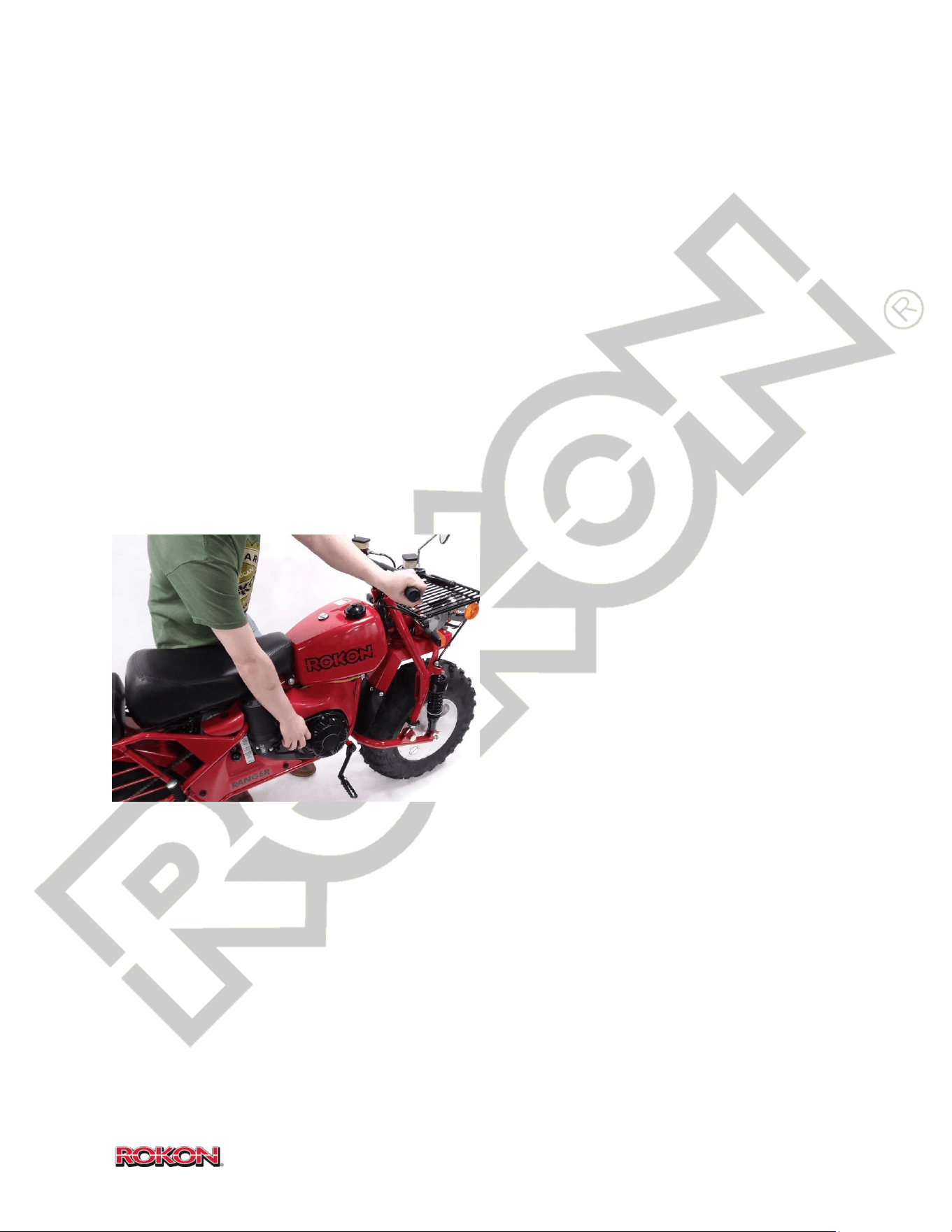
Riding basics – Once the engine is running smoothly, mount the seat and settle into a
comfortable stance for best balance and control function reach. Be sure that both feet can be
planted flat on the ground for the best possible controllability.
Select your desired gear range and gently apply throttle until you are riding in a balanced and
controlled manner. Spend some time familiarizing yourself with the handling characteristics of
the ROKON on a smooth, level surface prior to attempting more complex terrain.
24
©2019 Rokon International Inc. Printed in U.S.A. ROKON® and its logo are registered trademarks
Put the ball of the foot, rather than the instep on the
footrest. Pre-plan your route before attempting to
negotiate difficult terrain. Lean into the hill when climbing
switch backs.
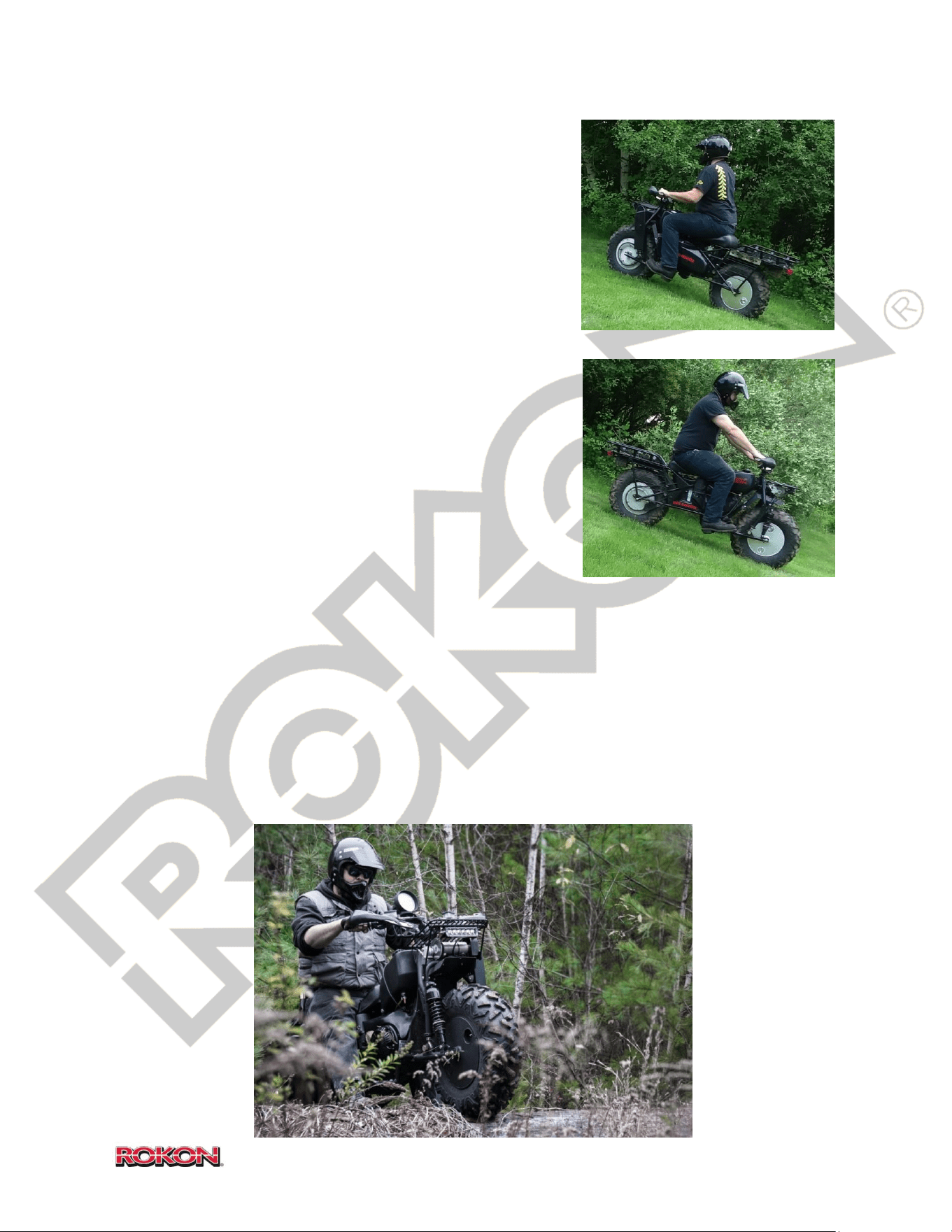
Traversing a sloping surface requires you to properly
position your weight to maintain proper balance. As you
travel across or up a slope, lean your body in the uphill
direction. It may be necessary to correct the steering when
riding on loose surfaces by pointing the front wheel slightly
uphill. When riding on slopes, be sure not to make sharp
turns either up or down hill, which could cause the ROKON
to turn over and potentially cause the operator and/or
passenger injury.
When riding downhill, shift your weight as far to the rear
and uphill side as possible. Use low gear. Whenever
possible ride straight downhill. Use good judgement on
limitations of grade angle. Turn into corners with the rear
brake only, so as not to slide the front wheel and lose steering control. Keep throttle slightly
engaged to utilize engine compression braking through the CVT system.
A ROKON handles much differently from a dirt bike or ATV. Both wheels are driven
simultaneously with the same amount of power and torque. The rear wheel is not designed to
freewheel or spin independently from the front. For this reason, attempting jumps or other
stunts may result in roll pin breakage or severe driveline damage. Avoid spinning both tires at a
high rate of speed in a low traction area before coming in contact with a high traction area
(example: rapidly spinning both tires on ice before reaching bare ground or shore).
25
©2019 Rokon International Inc. Printed in U.S.A. ROKON® and its logo are registered trademarks
Storing/Transporting Fluid in Drum Wheels – If your bike is equipped with Drum Wheels, you
can utilize them for the storing and transportation of liquids such as extra gasoline or potable
water. If gasoline is to be stored in a wheel, it is imperative that in only be used for gasoline for
the remainder of its lifetime. WARNING NEVER store drinking water in a wheel that has
previously been used to transport gasoline.
REFER TO HEALTH AND SAFETY INFORMATION AT THE BEGINNING OF THIS MANUAL BEFORE
HANDLING GASOLINE.
The fluid storage capacity of each wheel is 2.5 U.S. Gallons (9.5 Liters). To fill a wheel, rotate the
filler neck to the uppermost position and remove the fill cap. TIP Use a wide tipped flat head
screwdriver to remove the cap, the ROKON spark plug wrench can be used for this purpose.
NOTICE DO NOT overfill the wheel, particularly when storing Gasoline. Vapors must be given
room to expand. DO NOT transport or store liquid with water contents in freezing
temperatures.
Fill the wheel until the fluid is just below the fill cap threads. Reinstall fill cap and make sure it is
fully seated. To vent, loosen plug slowly when it is rotated to the topmost position.
TIP When extracting fluids from a wheel, the use of a hand transfer pump is recommended.
(ROKON hand pump shown, PN 109004).
26
©2019 Rokon International Inc. Printed in U.S.A. ROKON® and its logo are registered trademarks
10. FORDING AND FLOATING
WARNING Water crossings can be extremely hazardous, do not attempt to ford or float your
bike across swift moving bodies of water or areas where tidal currents may be present. Never
attempt water crossings that exceed your abilities as a rider.
Fording - The ROKON can be used to cross slow moving shallow water of up to a maximum of
22 inches in depth. Before entering the water, choose your path carefully. Enter where there is
no sharp drop off, and avoid rocks or other obstacles which may be slippery or unstable. Drive
slowly and carefully. Try to avoid changing course in the middle of a stream or you may find
that slippery rocks and changing currents might throw you off balance.
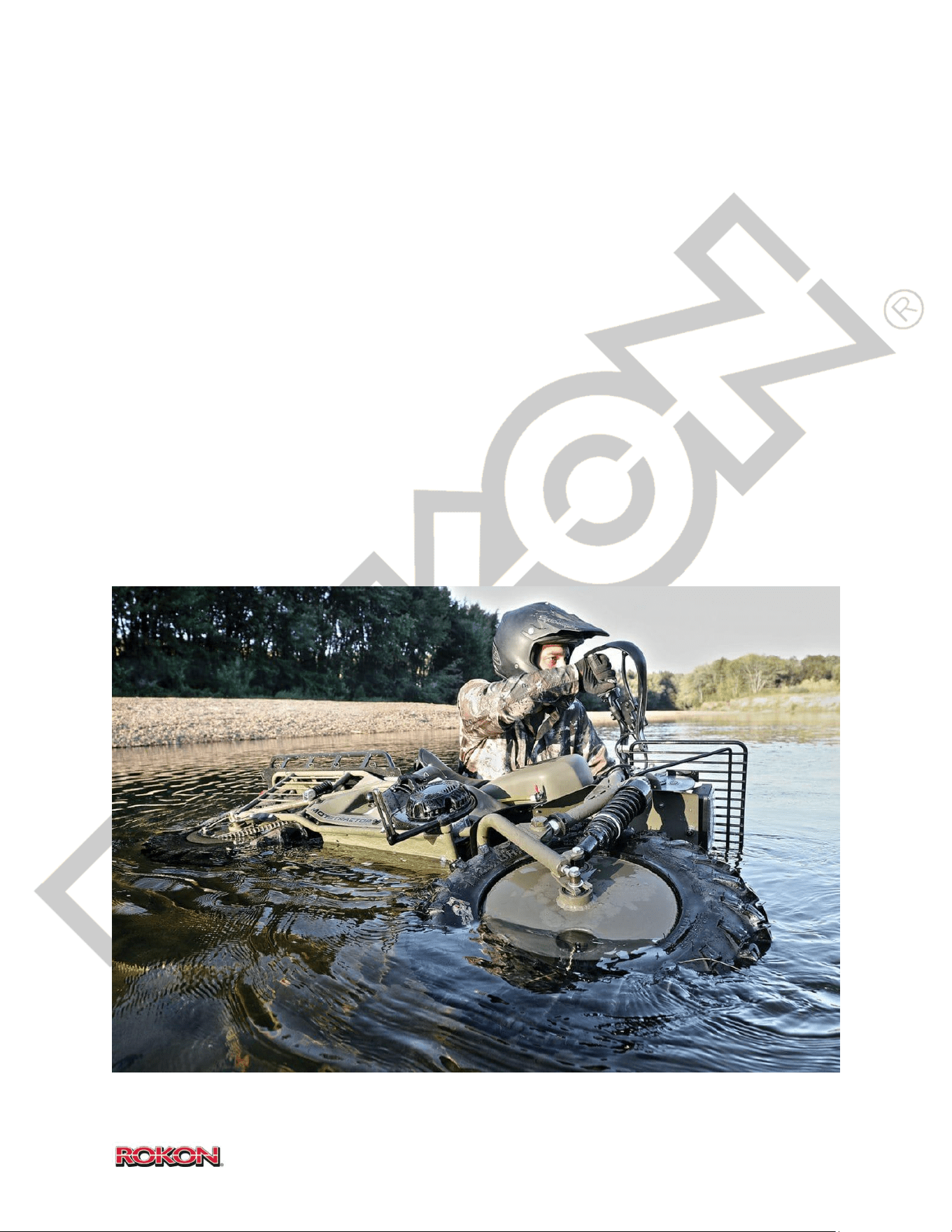
Floating - If the water body is over 22” in depth, shut the bike off and float your machine across
(EMPTY drum wheels only). Keep the air intake out of the water to avoid flooding the
combustion chamber. Always float the bike with the right hand side above water (as shown in
picture below). Immediately pull start bike once crossing is completed to ensure a clear
combustion chamber.

27
©2019 Rokon International Inc. Printed in U.S.A. ROKON® and its logo are registered trademarks
11. STREET LEGAL OPERATION
WARNING
ROKON RANGERS HAVE AN INCREASED SPEED CAPABILITY THAT ALLOWS THEM TO ATTAIN A
TOP SPEED OF APPROXIMATELY 35MPH WITH A COMBINED 200LB RIDER AND CARGO LOAD
(TOTAL VEHICLE WEIGHT BEARS UPON TOP SPEED). ALTHOUGH ROKON RANGER CAN BE
REGISTERD AS A MOTORCYCLE, IT IS STRONGLY ADVISED THAT IT BE RESTRICTED TO USE ON
ROADS WITH SPEED LIMITS NO GREATER THAN 35MPH.
THE STREET LEGAL CAPABILITY OF THE ROKON IS INTENDED FOR SHORT DISTANCES ON
SECONDARY ROADS ONLY.
NEVER OPERATE ON RESTRICTED ACCESS HIGHWAYS. ALWAYS OBEY THE LAWS OF THE ROAD
PERTAINING TO MOTORCYCLE OPERATION IN YOUR STATE.
DO NOT OPERATE A STREET LEGAL ROKON ON A PUBLIC ROADWAY WITHOUT POSSESSING
THE PROPER LICENSE AS REQUIRED IN YOUR STATE.
Before You Ride – It is very important to analyze traffic and weather conditions prior to taking
your RANGER on the street.
Understand that your machine will handle much differently on paved surfaces than it does off
road.
Always wear DOT approved safety gear and whenever possible take steps to make yourself as
visible as possible, it is advised that you wear brightly colored apparel or reflective materials
even if you are riding in daylight.
DO NOT remove factory installed reflectors or reflective safety material.
Inspect your bike to verify that all signaling equipment including horn and turn signals are
functioning properly.
Ride with your headlight on at all times whenever you are riding on the street.
Riding in traffic – Select the proper speed range while riding on the street so as not to impede
regular traffic flow.
Maintain a reasonable distance between you and the vehicle in front of you.
Be aware of your surroundings at all times. In addition to use of side view mirrors, it is very
important to also perform shoulder checks before changing lanes or merging.
28
©2019 Rokon International Inc. Printed in U.S.A. ROKON® and its logo are registered trademarks
Remember that soft shoulders rumble
strips and unpaved roadways can be
hazardous to any motorcycle
operating on a public road. Always
stay to the left of the center of your
lane to avoid road debris and oil slicks,
paired riding or “lane splitting” with
another motorcycle is not advised and
may be illegal in some states.
Speedometer Adjustment – Pressing the top button on the right side of the speedometer will
switch the top display from current time to electrical system voltage.
Pressing the bottom button will cycle
the bottom display from odometer,
trip odometers, hours, and most
recent maximum speed.
By holding down the top button
alone, you will switch the display
between a 12 hour and a 24 hour
clock.
By holding down the bottom button
alone, you will switch the
measurement units between
Kilometer and Miles.
All settings regarding tire circumference and sensor quantity are set by the factory.
Adjustments can be made to time of day, illumination settings and unit of measure if needed.
By holding down both buttons together on the right side of the speedometer, you will enter the
adjustment mode. The top button will allow you to cycle through adjustable settings while the
bottom button will perform the required changes.

29
©2019 Rokon International Inc. Printed in U.S.A. ROKON® and its logo are registered trademarks
12. CLEANING, STORAGE AND TRANSPORTATION
Cleaning – Keeping your ROKON clean is an essential part of periodic maintenance and can
greatly extend the lifespan of your machine. Before cleaning your ROKON, be sure to cover your
air filter or air cleaner housing to prevent moisture from entering your carburetor or
combustion chamber.
Avoid the use of excessively high pressure nozzles or sprayers that can potentially cause
damage to sensitive areas such as gasket seams, electrical connections, decals and gearbox
vents. Do not spray high pressure water on drive chains. Rinse your machine thoroughly paying
close attention to the bottom of the frame and the inside of the fenders. Use soapy, warm
water on a clean sponge or brush to clean your ROKON. Rinse off and dry machine thoroughly
using a clean terry cloth.
Standard automotive cleaner waxes can be used to polish painted surfaces and plastic fairings.
Apply and remove wax according to manufactures recommendations. DO NOT leave excess wax
buildup on plastic surfaces. Care must be taken to prevent wax from contacting decals, mud
flaps, brake hoses and vinyl seat material. Avoid cleaners that are known to damage plastic and
painted surfaces. DO NOT apply cosmetic cleaners of any kind to brake discs.
Seats can be cleaned with a light duty vinyl or leather cleaner. DO NOT use cleaners that leave
an oily residue on seats, foot pegs or hand grips.
Storage – It’s important to ensure that your bike is stored correctly after each use. Make sure
that your ROKON is clean and dry before storing. Store in a dry location, out of direct sunlight
and free of invasive critters. Use a weatherproof cover if you intend to store your machine
outdoors.
If you intend to store your machine for a period of 3 months or more, additional steps must be
taken to ensure that is ready to use when removed from storage. Fill your fuel tank with fresh
gasoline. Add a high quality fuel stabilizer that is rated for long term storage and helps prevent
ethanol breakdown. Follow mixture instructions outlined by the manufacturer. Start and run
your machine for a period of at least 15 minutes, this will ensure that fresh fuel and stabilizer
has made its way into the carburetor. Once you have placed your ROKON in its storage location,
shut off both fuel tank and carburetor fuel flow valves. Disconnect the negative battery lead, if
machine will be stored in temperatures below 32 degrees, remove battery from bike entirely
and store it in a climate controlled environment. NOTICE – DO NOT store battery on a bare
concrete floor. Keep out of reach of children. It is recommended that you apply electrical tape
over exposed battery terminals while in storage to prevent accidental arcing or discharging.
30
©2019 Rokon International Inc. Printed in U.S.A. ROKON® and its logo are registered trademarks
Transportation – When transporting your ROKON, care must be taken to prevent damage to
the machine and ensure that it arrives at its destination safely.
If you are loading your ROKON into a pickup truck or van, use a ramp or set of ramps that were
designed specifically for this purpose. NEVER use boards, blocks or other homemade devices for
this task. Make sure the ramp you have selected has a rated capacity capable of handling the
full weight of the machine and any accessories that may be installed. (See the Specifications
section to determine the weight of your machine). WARNING DO NOT attempt to ride your bike
up a loading ramp, place your machine in neutral and push it up the ramp. Get someone to
assist you with this task if required. NOTICE Prior to transporting your ROKON, move the fuel
valves on the fuel tank and carburetor to the “OFF” position to prevent engine flooding or
hydro-locking.
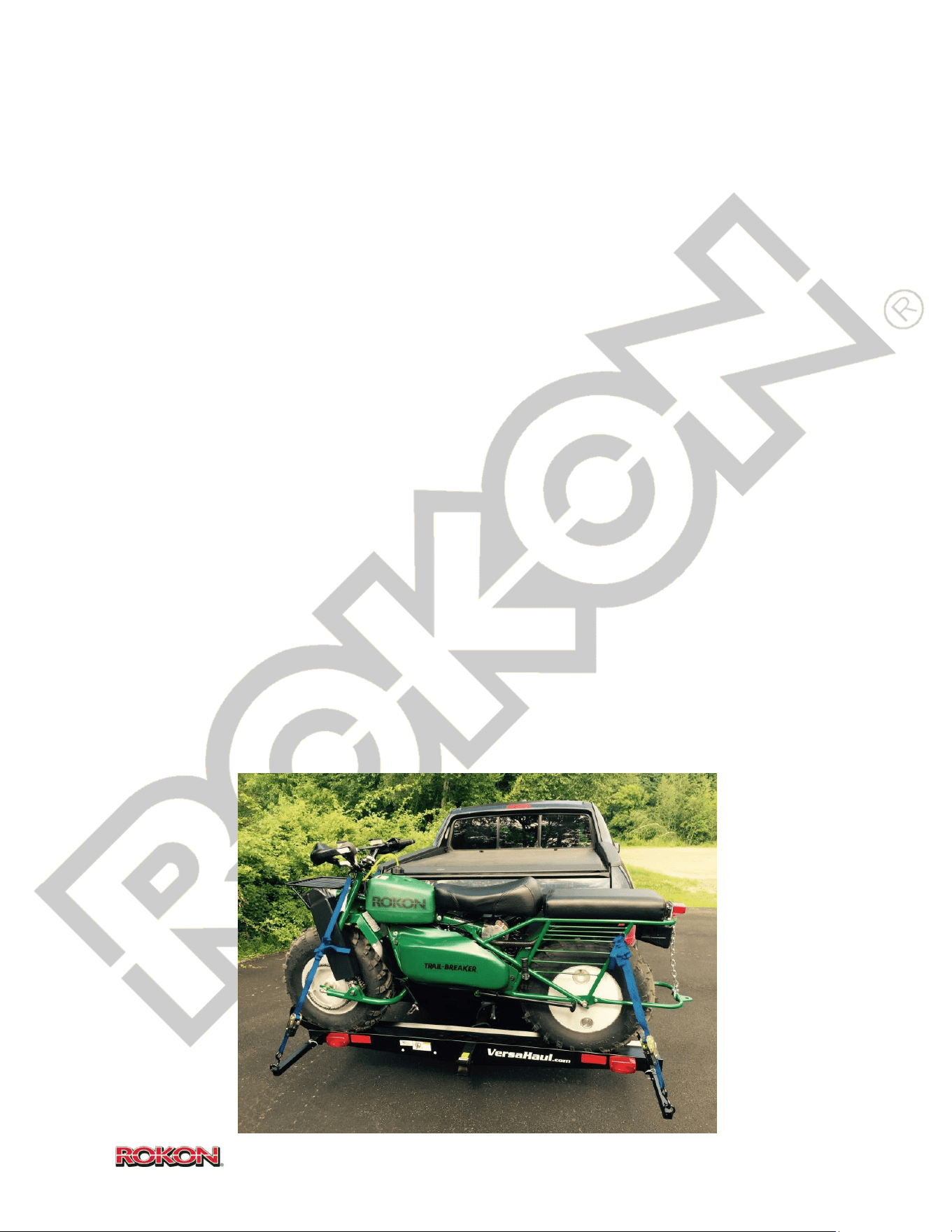
When securing your machine down to the surface of a trailer, truck bed or cargo area; the use
of ratchet straps, turnbuckles or lever binders is recommended. Cam buckles or “cinch straps”
can also be used. TIP Use two binders on the front of your machine and two binders on the rear
for best possible retention. Attach one end of each binding device to either inside corner of the
handlebars and the other ends as low as possible on either side of the cargo deck. Tighten
binders until the bike is in a fully upright position and suspension (if equipped) is compressed.
Attach the ends of the remaining binders to the rear section of the frame and the other ends as
low as possible on the cargo deck. Avoid pinching wiring and brake hoses with binding
equipmet.
If you are using a “Wheel-Free” hitch tube carrier, follow the instructions provided to you by
the manufacturer for loading and binding. NOTICE DO NOT exceed the rated capacity of the
carrier or your vehicle.
31
©2019 Rokon International Inc. Printed in U.S.A. ROKON® and its logo are registered trademarks
13. REMOVAL OF ACCESS / MAINTENANCE PANELS
WARNING
NEVER OPERATE YOUR ROKON WITHOUT ALL ACCESS PANELS AND CHAIN GUARDS IN PLACE.
DO NOT REMOVE ACCESS PANELS WHILE BIKE IS RUNNING.
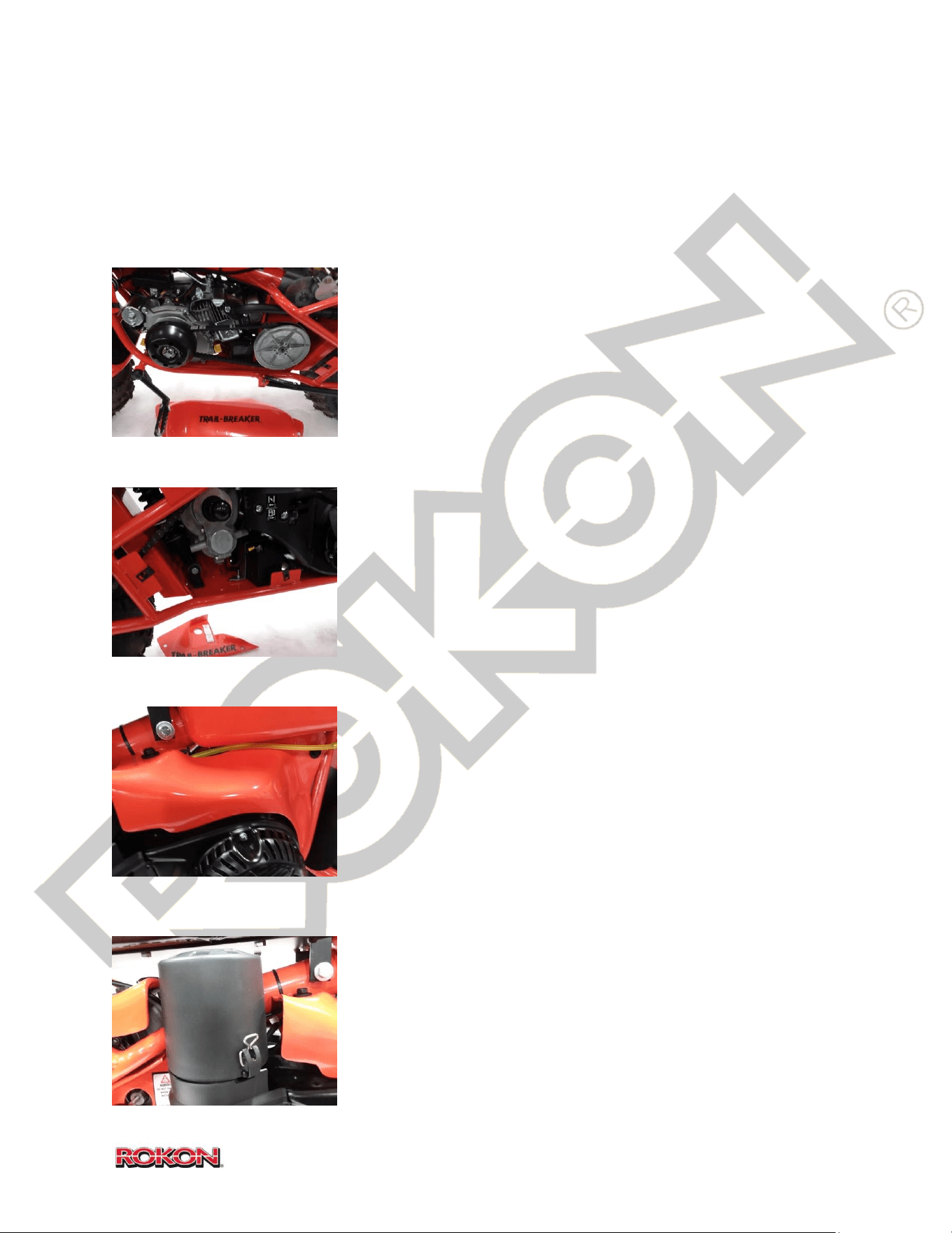
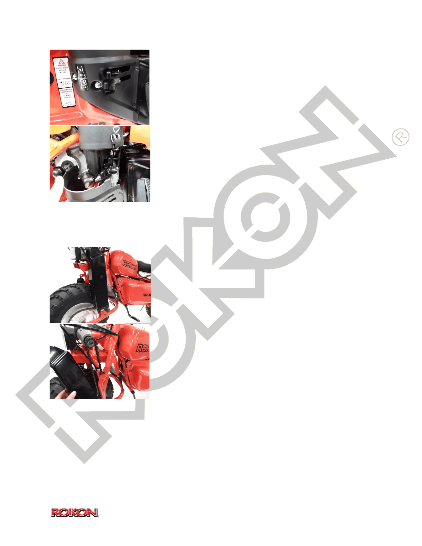
CVT Housing Cover (Left side) – Rotate key switch to the “OFF”
position and remove key. Remove the two ½”bolts retaining the
cover to the bike. Remove cover.
Battery access cover (Right side, bottom) – Place the gear
selector knob in first gear position (all the way out). Remove the
two ½”bolts retaining the cover to the bike. Remove cover.
Electrical access cover (Right side, above engine) – Remove the
two ½”bolts retaining the cover to the bike. Remove cover. On
Power Point equipped bikes, disconnect power and ground
wires leading to Power Point to completely remove cover from
bike.
Air Cleaner cover – Release the retaining clip holding the air
cleaner cover to the base. Rotate housing clockwise until rear
retaining tab is free. Remove cover.
32
©2019 Rokon International Inc. Printed in U.S.A. ROKON® and its logo are registered trademarks
Carburetor cover – Move the carburetor fuel lever to the “OFF”
(rearward) position, move the choke lever to the “ON”
(rearward) position. Remove the two 10mm nuts and the two T-
20 screws retaining the cover to the engine. Remove cover. TIP
It is easier to remove the carburetor cover once the battery
access cover has also been removed.
Front chain guard – Remove the ½” bolt retaining the guard to
the front end. Remove guard. TIP This procedure is the same for
Autograb and standard front ends.
33
©2019 Rokon International Inc. Printed in U.S.A. ROKON® and its logo are registered trademarks
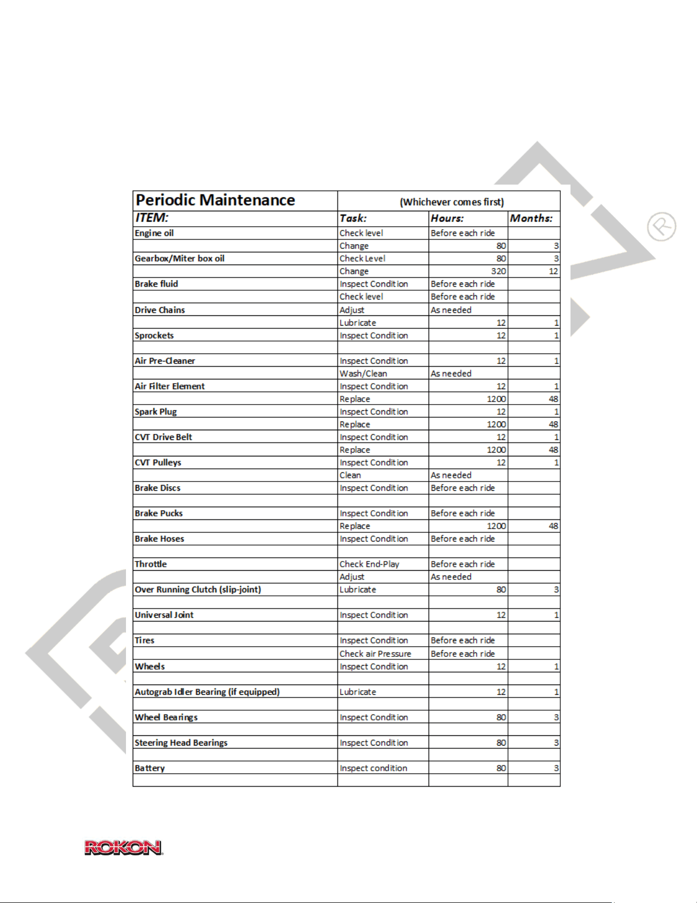
14. PERIODIC MAINTENANCE AND ADJUSTMENTS
In order to ensure the safety of the rider and protect the longevity of your ROKON, it’s
important to perform routine care and maintenance as described in the table below. Most of
these procedures that follow are very simple and can be easily performed by the owner.
34
©2019 Rokon International Inc. Printed in U.S.A. ROKON® and its logo are registered trademarks
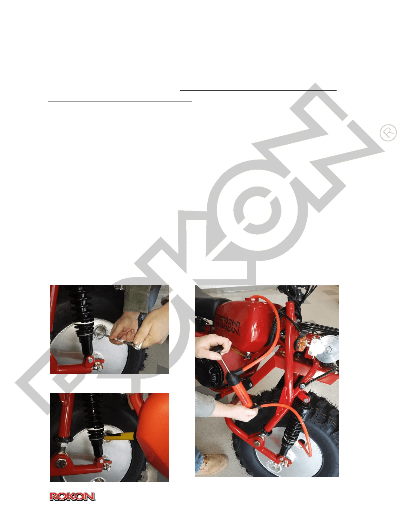
Drive Chain Adjustment – Chain adjustments will be one of the most frequent service items
required on your ROKON. It is important to examine the chain tension and sprocket alignment
before every ride. Failure to do so can result in the chains slipping off the drive sprockets or
even chain breakage. The following is a procedure for chain adjustment and sprocket
alignment.
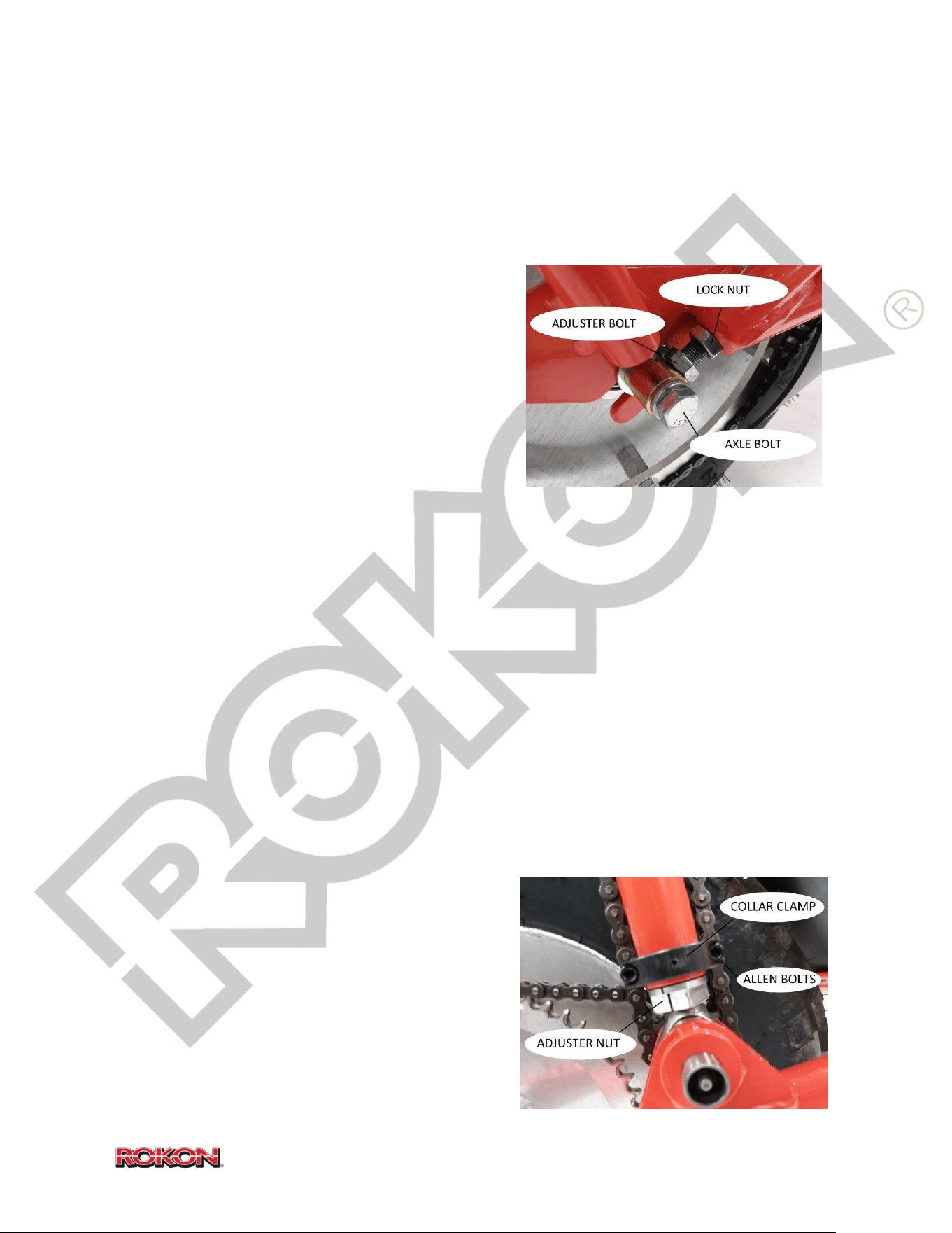
Symptom: Rear chain or Scout front chain loose
1. Using a 9/16” wrench, loosen adjuster bolt
lock nuts on frame tube ends or fork ends
(two 9/16” wrenches will be required).
2. Loosen axle bolts slightly.
3. Rotate both sides’ adjuster bolts
alternately counter-clockwise to tighten
the chain, maintain consistent revolutions
(or fractional revolutions) on both adjusters to reach desired chain tension. (about
3/4” – 1/2” deflection at center is acceptable)
4. Tighten adjuster bolt lock nuts and axle bolts. Verify that spacer is contacting adjuster.
Symptom: Rear sprockets or Scout front sprockets misaligned
1. Raise the bike so that the tire is at least six inches off the ground, support it securely.
2. Loosen the adjuster bolt lock nut on the non-sprocket side. Loosen non-sprocket side
axle bolt.
3. Adjust non-sprocket side adjuster bolt in or out (as required) periodically rotating the
tire forward until chain is running smoothly and centered on both sprockets.
4. Tighten adjuster bolt lock nuts and axle bolts.
5. Upon completion of alignment, review chain adjustment procedure.
Symptom: Vertical chain loose (Autograb)
1. Loosen collar clamps using a 3/16” Allen
wrench.
2. Using a 7/8” (or adjustable) wrench, rotate
aluminum adjuster nuts at bottom of tubes
counter-clockwise alternately to tighten the
chain, maintain consistent revolutions (or
fractional revolutions) on both nuts to reach
35
©2019 Rokon International Inc. Printed in U.S.A. ROKON® and its logo are registered trademarks
desired chain tension. (about 1/2” deflection at center is acceptable)
NOTICE Vertical chain sprocket alignment is set by the factory; altering this alignment is not
advised. Adjust for tension only.
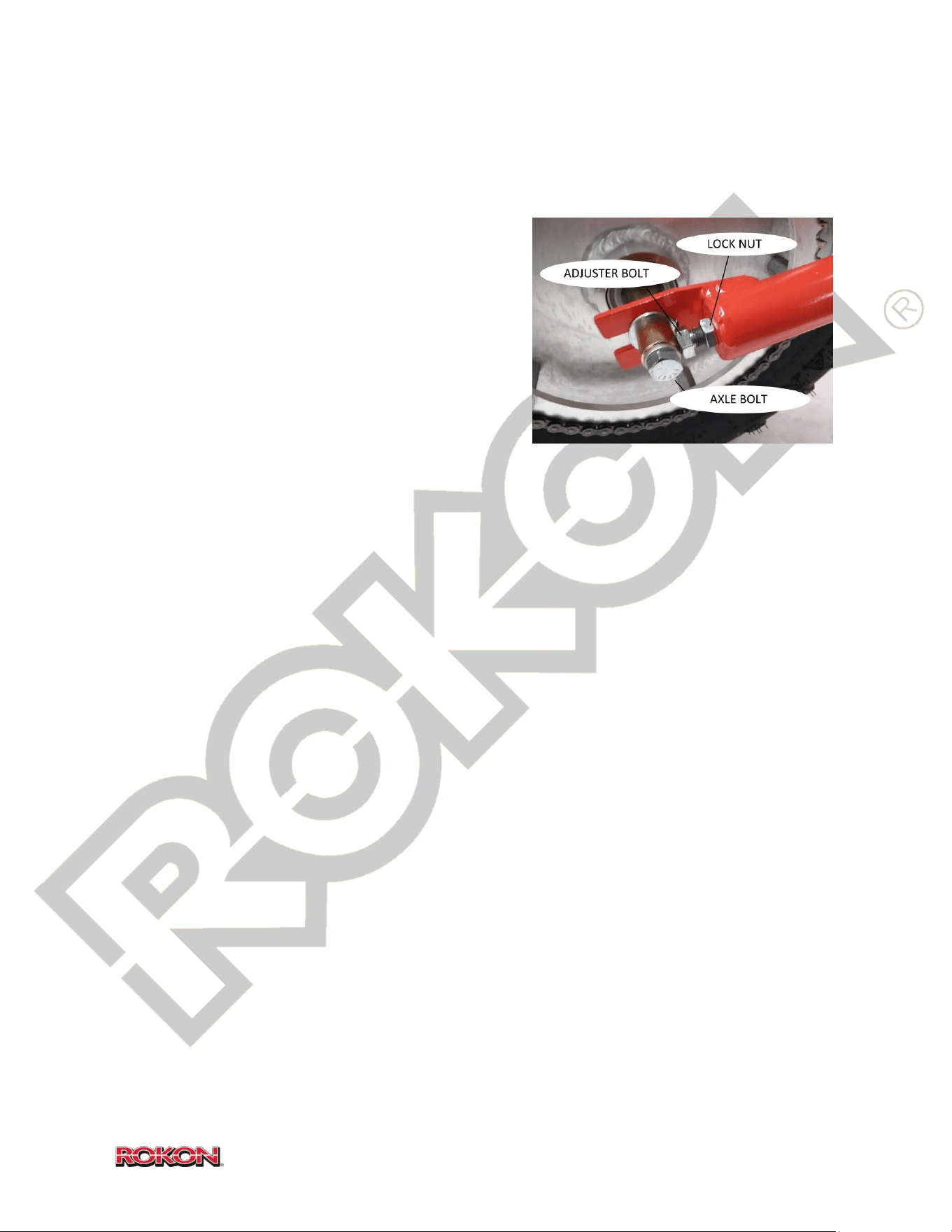
Symptom: Horizontal chain loose (Autograb)
1. Using a 9/16” wrench, loosen adjuster bolt
lock nuts on swing arm tube ends (two 9/16”
wrenches will be required).
2. Loosen axle bolts slightly.
3. Rotate both sides’ adjuster bolts alternately
counter-clockwise to tighten the chain,
maintain consistent revolutions (or fractional
revolutions) on both adjusters to reach
desired chain tension. (about 1/4” deflection at center is acceptable)
4. Tighten adjuster bolt lock nuts and axle bolts.
Symptom: Horizontal sprockets misaligned (Autograb)
1. Raise the front of the bike so that the tire is at least six inches off the ground, support
it securely.
2. Loosen adjuster bolt lock nut on right side (shock side). Loosen right side axle bolt.
3. Adjust right side adjuster bolt in or out (as required) periodically rotating front tire
forward until chain is running smoothly and centered on both sprockets.
4. Tighten adjuster bolt lock nuts and axle bolts.
5. Upon completion of alignment, review chain adjustment procedure.
Keep chains well lubricated and free of foreign material, failure to do so can result in premature
chain wear and breakage. There are many different chain lubricants available and the one you
chose will depend on your environment. Be sure to choose a lubricant that is tacky enough to
remain on the chain without slinging off at speed. Replace with #40 Roller chain.
36
©2019 Rokon International Inc. Printed in U.S.A. ROKON® and its logo are registered trademarks
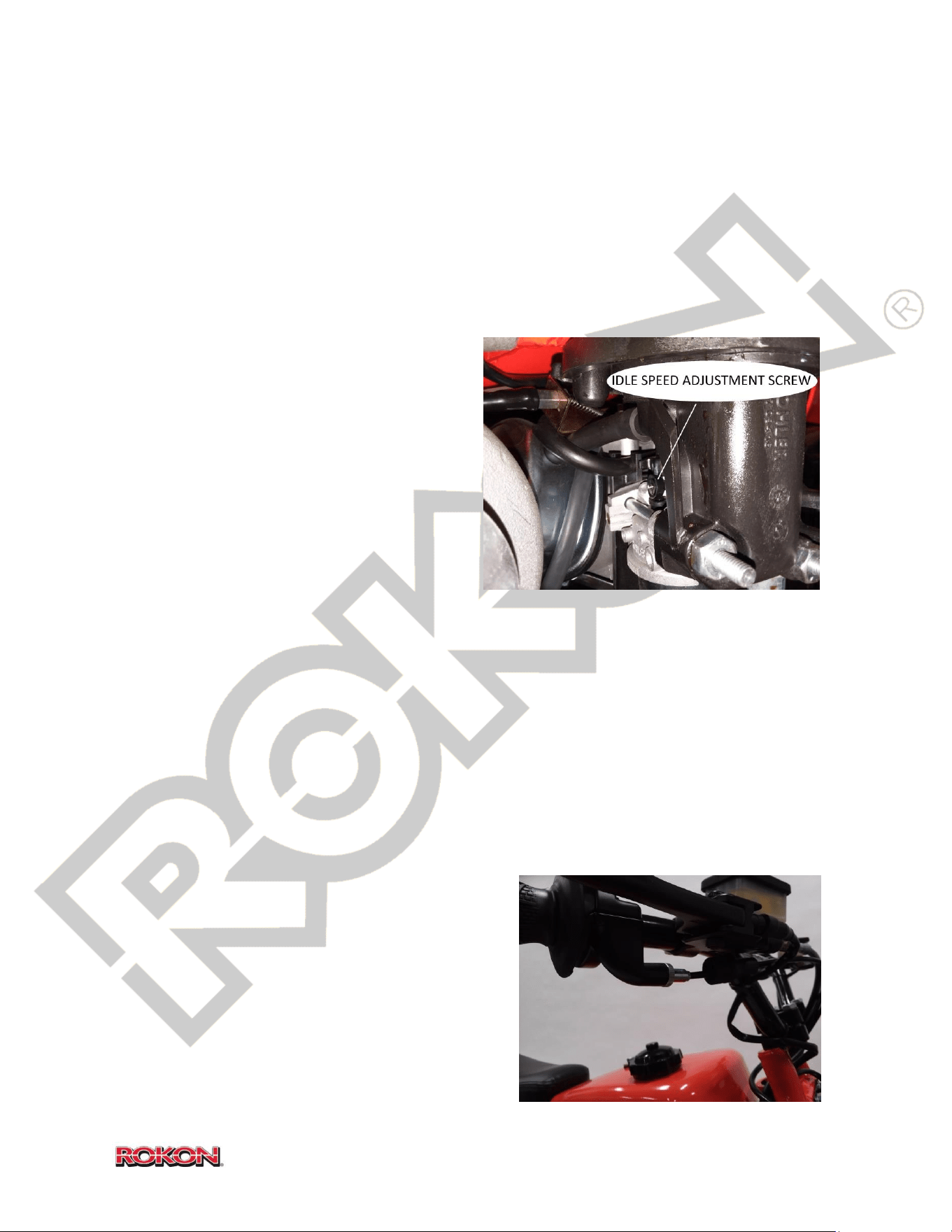
Idle Speed Adjustment – ROKON sets all idles specifically according to each bike. Idles are set
after a 15 minute warm-up period and are all set at approximately 200 feet above sea-level.
Elevation, relative humidity, ambient temperature and oil viscosity can all affect idle speed. It is
important to understand that no adjustments to the idle should be attempted on any bike
unless the engine has been properly broken-in for a period of at least 3 hours. Out-of-the-box
adjustments may be required if you live in an area with a nominal elevation above 4000 feet.
Seasonal idle adjustments may also be required depending on temperature.
NOTICE Do not attempt to adjust idle unless
engine has been warmed for 10 – 15 minutes
and has still failed to idle normally.
1. Remove carburetor cover.
2. Locate idle adjustment screw on rear of
carburetor above fuel bowl.
3. To increase idle speed, rotate idle
adjustment screw clockwise. Rotate
counter-clockwise to decrease.
TIP Use a small right-angle driver with a
Phillips head.
Idle is too LOW if engine is stalling after warm-up.
Idle is too HIGH if the clutch can be heard engaging or if the transmission makes a clicking or
grinding sound when a gear change is attempted.
NOTICE A high idle that results in a clicking noise from the transmission WILL result in
premature failure of driveline components. If possible, set idle on the low side to avoid this.
Throttle end-play adjustment – Throttle end-play is
set by the factory to provide you with optimal
throttle response and proper throttle release spring
tension. As your machine ages, it may be necessary
to adjust throttle end-play to make up for excess
throttle “dead zone” and improve throttle
response.
37
©2019 Rokon International Inc. Printed in U.S.A. ROKON® and its logo are registered trademarks
NOTICE DO NOT use throttle end-play adjustment to adjust idle speed.
1. Slide dust boot off of throttle cable adjuster.
2. Loosen lock nut.
3. Rotate inner adjuster collar until excess end-play is removed. DO NOT adjust beyond the
point of increasing engine speed governed by idle speed screw.
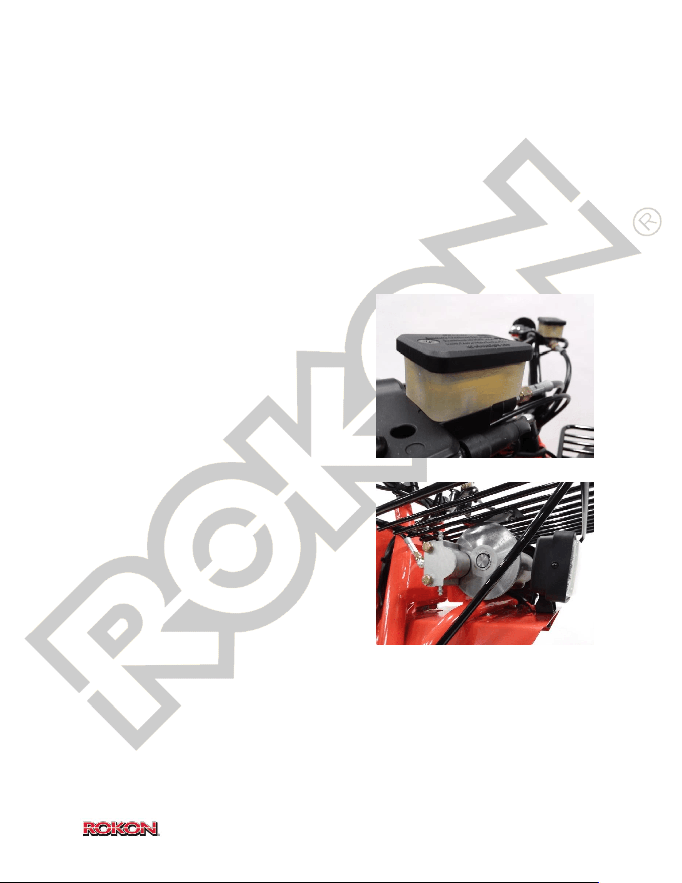
Brake System Maintenance – The brake system on all ROKON models is a relatively
maintenance-fee setup. It is important however to perform periodic checks to ensure that it is
working properly and is free of foreign contaminants.
NOTICE Use ONLY DOT-3 or 4 brake fluid in all
ROKON brake systems.
1. Inspect reservoirs for proper fluid level and
condition. Check reservoirs for leaks and
ensure that fill caps are properly seated.
2. Inspect brake lines for leaks, cracking,
kinking or other damage.
3. Inspect calipers for leaks or damage.
4. Inspect brake pucks for irregular wear.
If hydraulic brakes feel spongey, “bleeding” them
may help. Do not pressure bleed with more than 5
PSI.
1. Orient handlebars to ensure brake
reservoirs are level. Remove cover of
malfunctioning brake reservoir and fill with
hydraulic fluid to maximum line.
(Throughout bleeding process, do not allow
fluid to drop below minimum line.) Replace cover but leave loose to allow reservoir to
vent during bleeding.
2. Find the corresponding brake caliper to the reservoir you have filled. Loosen upper
bleeder screw on caliper.
3. Grasp brake lever and slowly engage brake to bleed. Air bubbles and hydraulic fluid
will flow out of the loosened bleeder screw.
38
©2019 Rokon International Inc. Printed in U.S.A. ROKON® and its logo are registered trademarks
4. Before brake lever is fully seated, re-tighten bleeder screw on caliper. Allow brake
lever to reset to resting position.
5. Refill brake reservoir as necessary.
6. Repeat steps 1-5 until bleeder screw is releasing a constant flow of hydraulic fluid
with no air bubbles. Brake handle will feel firm when bleeding is complete.
7. Tighten reservoir cover until it is sealed and seated.
The floating brake disc must be free to move axially so that the moveable puck will push against
the fixed puck. Otherwise, unequal wear or bending of the disc will result. Lubricate the shafts
and keys where the brake discs ride with anti-seize. Proper clearance between the puck and the
disc is .010” minimum per side to a maximum of .030” per side when new. Discs must be free of
dirt and grease for maximum life and braking action.
Replacement of the brake “pucks” or friction material is performed as follows:
1. Be sure no pressure is applied to the caliper during puck replacement.
2. Use a ½” wrench and/or socket to remove the two SAE grade 8 hex bolts. This will
dismount and disassemble the caliper, exposing the Pucks for replacement.
3. Remove the flat head screws that hold the Pucks in place on each side of the caliper.
Remove Pucks from Housing and Dead Side Housing.
4. Place new Pucks into Housings. Replace flat head screws; tighten to hold Pucks in
place. (Note: Screw head will fit into recessed area of Puck. Be sure only friction material
will contact disc when reassembled.)
5. Reassemble caliper and mount as before.
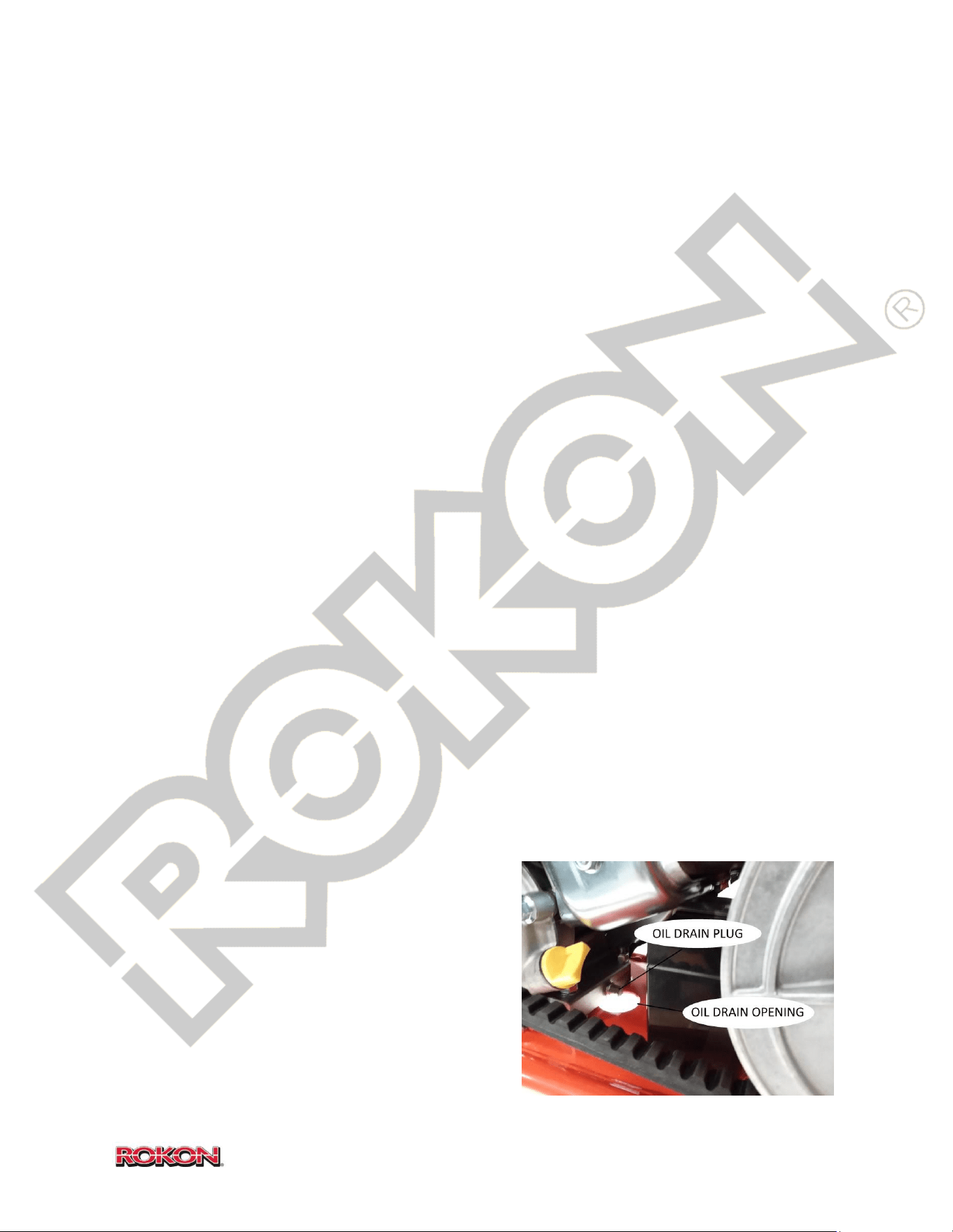
Changing the oil – Oil changes should be performed
every 6 months (more often if bike experiences
frequent extended usage).
1. Set bike in a level position. TIP You can
set the bike in a level position by placing
a block of wood beneath the kickstand
foot.
2. Remove the CVT housing cover.
39
©2019 Rokon International Inc. Printed in U.S.A. ROKON® and its logo are registered trademarks
3. Place a container beneath the frame drain hole.
4. Using a 10mm wrench, remove the oil
drain plug at the back of the engine. Be
careful not to lose the sealing washer
on the drain plug.
5. Once all old oil has been drained,
replace drain plug. DO NOT over-
torque.
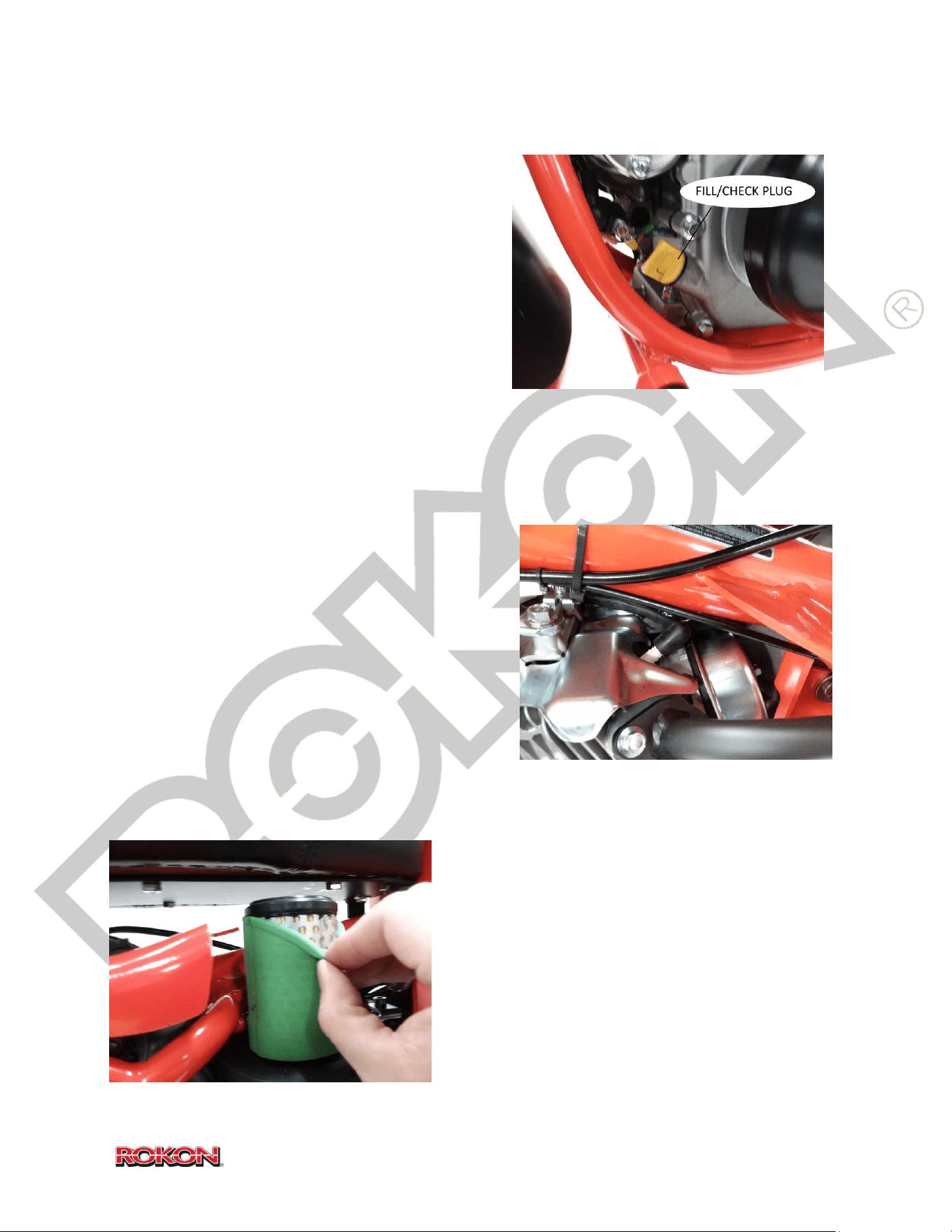
6. Refill with .6 QT of fresh 10W-30 engine
oil from the FORWARD fill/check hole.
7. Start engine and check for leaks.
Replacing or cleaning the spark plug – ALERT Use caution servicing the spark plug while the
engine is hot.
TIP to ensure quick and easy removal of the spark
plug, a purpose-built ROKON spark plug wrench is
highly recommended (PN 108059).
It is important to inspect the spark plug every 100
hours of operation. When replacing or cleaning the
spark plug, make sure you set the gap on the plug
to .76 mm or .030 in. Replace with Champion
RC12YC or equivalent.
Air filter inspection and replacement – NOTICE Operation of the engine without the air cleaner
in place can lead to severe engine damage.
It is recommended that the air cleaner be inspected
before each ride. It is also advised that the pre-
cleaner element be washed regularly as needed.
Remove the pre cleaner from the paper element
filter and wash with warm water detergent. Rinse
thoroughly until all traces of detergent is gone.
Allow to dry completely before reinstalling over
paper element. Replace paper element every 100
hours (more frequently if excessively dusty
conditions are present).
40
©2019 Rokon International Inc. Printed in U.S.A. ROKON® and its logo are registered trademarks
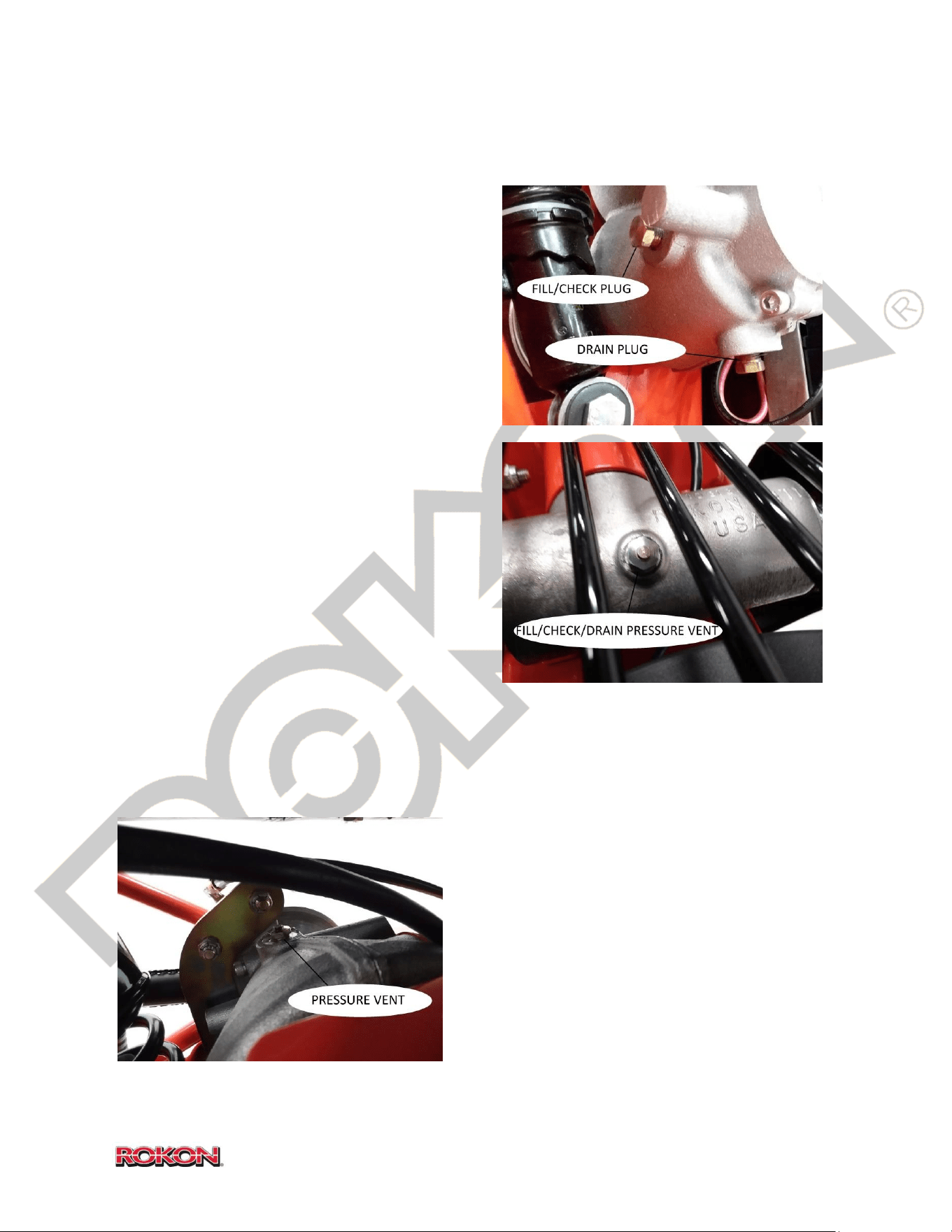
Changing miter box and transmission oil – The transmission and miter box oil should be
checked every 3 months. It should be changed annually.
There is a check plug on the rear of the
transmission that can be removed to verify oil
level and condition. Drain the transmission oil by
removing the drain plug at the bottom of the
transmission case.
The miter box has a single fill/check/vent plug on
top of the housing that can be used for filling and
checking. Draining of miter box oil can be
accomplished by using an automotive fluid
extractor with a narrow, rigid tube. Alternatively,
the miter box can be removed from the front end
and drained upside-down.
TIP You can use a zip tie to dip the miter box to
verify condition and level.
Atop both the miter box and transmission is a
vented plug, it is important to make sure this
vent is moving properly by pulling the tip out and
verifying that the internal spring seats it back in
place. Failure of this vent can lead to internal pressurization of the gear box and seal leakage.
Use EP 80W-90 gear oil in both the miter box and transmission.
Miter Box capacity – 2.5oz
Transmission capacity – 6oz
NOTICE DO NOT OVERFILL Seal leakage will occur.
41
©2019 Rokon International Inc. Printed in U.S.A. ROKON® and its logo are registered trademarks
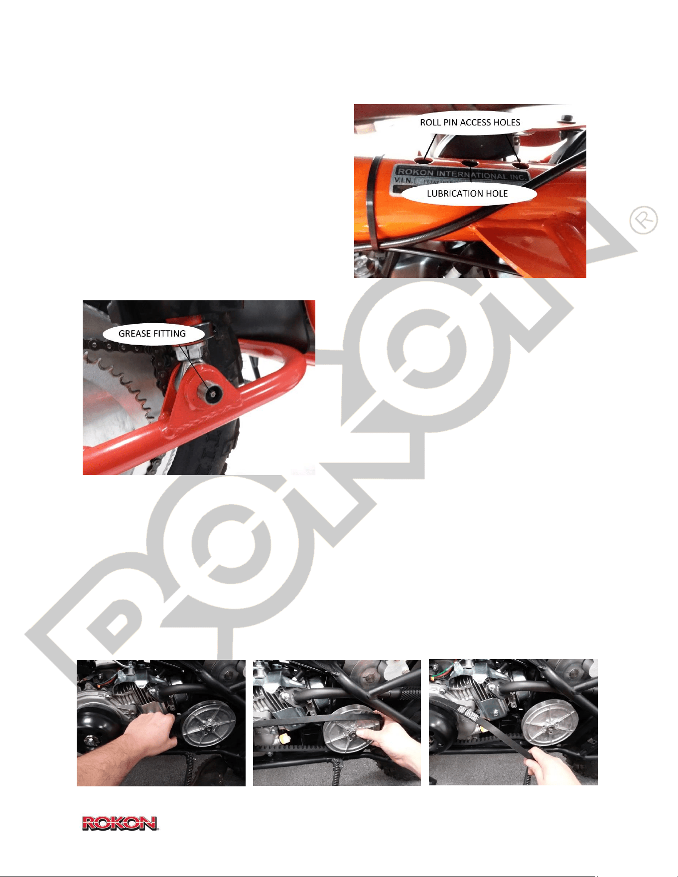
Over-running clutch lubrication – The over-running clutch (or slip joint) is an essential
component to the operation of a ROKON. It
allows the front wheel to rotate faster than the
rear when riding through a sharp turn on a hard
surface. If kept properly lubricated, this
component will work seamlessly and will require
very little maintenance. Locate the inspection
and lubrication holes in the main frame tube
under the front seat. Lubricate the over-running
clutch with a few drops of 80W-90 gear oil into
the inspection hole every six months.
Autograb idler sprocket bearing lubrication
(Ranger and Trail-Breaker only) – There is one
grease fitting on Ranger and Trail-Breaker models,
it is located on the left side of the bike at the end
of the idler sprocket shaft. It is recommended that
this grease point gets at least one pump of #2
Lithium grease every 20 hours (more often when
frequently exposed to deep mud or water
crossings).
Belt Replacement – The drive belt should be inspected for wear and proper tension regularly.
Replacement should be determined based on wear. To replace, firmly grasp the belt and tug it
up and down until the faces of the rear driven pulley separate slightly and allow for additional
belt slack. Once the belt is loose it can be removed by prying one edge off the top of the rear
pulley and rotating the pulley clockwise until the belt walks itself out of the groove. Installation
of a new belt is performed by seating the belt in place on the torque converter (forward pulley)
and starting the belt seat at the top of the rear pulley. Firmly grasp the rear pulley and rotate it
clockwise until the belt walks itself into place and seats fully in the groove of the rear pulley.
42
©2019 Rokon International Inc. Printed in U.S.A. ROKON® and its logo are registered trademarks
Tire inspection and pressure check – ALERT it is highly advised that any tire replacement or
repairs be performed by an experienced tire technician.
Inspect tires before each ride. Note the condition of the tread and check for the presence of
foreign objects that may have punctured the tire.
Tire pressures should be set between 5-7psi off road and 7-10psi on road. NOTICE Under no
circumstances should the front tire pressure exceed that of the rear, driveline damage will
result. DO NOT exceed tire manufacturer’s recommended pressure setting.
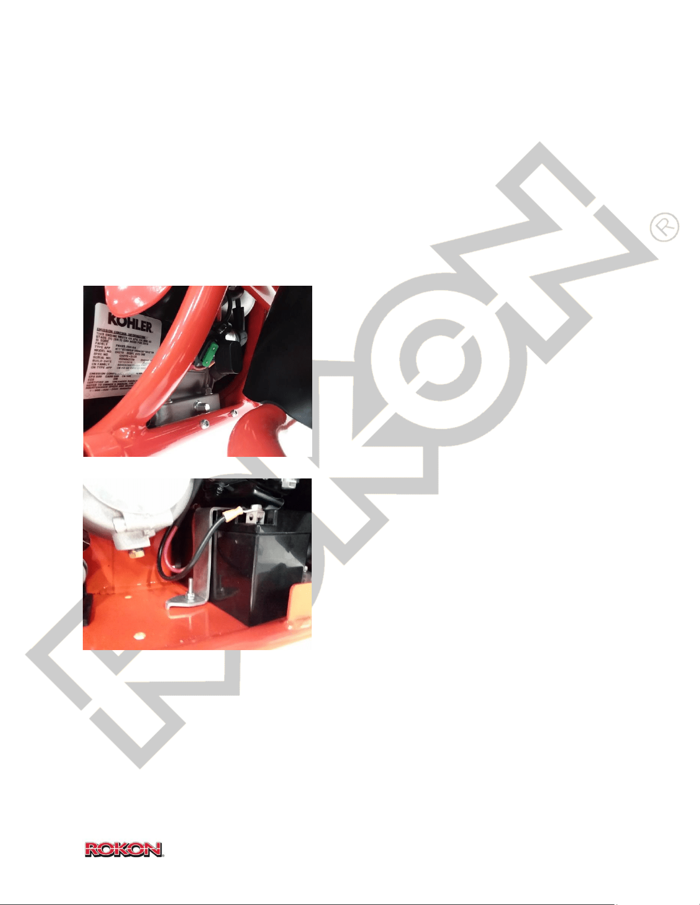
Fuse Replacement – Replace fuse with standard 25
amp ATO blade type fuse. Fuse holder is located on
the front of the engine beneath the starter solenoid.
Replacing the battery – ALERT ALWAYS disconnect
the negative battery terminal before attempting to
remove the battery from its hold-down location.
The battery condition should be checked regularly by
verifying the output voltage. It should remain
between 11 and 13 volts. Voltage can be checked
with a voltage meter or multi meter, on street legal
models, the voltage can be checked via the
speedometer.
If you suspect your battery is in need of replacement, disconnect negative battery terminal and
remove the battery hold-down bracket. Remove the battery from the bike and disconnect
positive terminal. Replace with a quality AGM battery of the same group size and dimensions.
TIP A battery tender can be used to prolong the life of your battery and ensure consistent
cranking amperage during periods of inactivity. Refer to battery tender manufacturer
recommendations to find a unit that is right for your application.
43
©2019 Rokon International Inc. Printed in U.S.A. ROKON® and its logo are registered trademarks
15. TROUBLESHOOTING GUIDE
This section is for diagnosing and addressing potential problems with your ROKON. It is strongly
suggested that the user consult this guide prior to contacting the factory should you have a
problem. Many of the problems outlined within are relatively simple to address and reading
this guide can prevent unnecessary purchase and replacement of parts that may be in perfect
working order. Should you need help diagnosing a problem or replacing a component, our
technical support team is ready to assist you. Call the factory at (603) 335-3200, tech support
hours are Mon-Fri 8AM to 4PM EST. You can also email your troubleshooting questions to
[email protected] and one of our technical advisors will respond as soon as possible.
Please refer to the warranty information in sections 19 and 20 prior to addressing problems.
Troubleshooting Index
SUBJECT PAGE#
Engine 44
Fuel/Air System 46
Transmission and Driveline 47
Miter Box and Universal Joint 48
Chain Drive 49
CVT System (Clutch, Belt and Rear Pulley) 50
Brakes 51
Electrical and Ignition System 53
Handling and Performance 55

44
©2019 Rokon International Inc. Printed in U.S.A. ROKON® and its logo are registered trademarks
TROUBLESHOOTING GUIDE
ENGINE (See also KOHLER CH270 manual)
Symptom: Fails to start but does rotate (see also FUEL/AIR SYSTEM) *Causes listed in order of probability
- If pull starting, Key switch is not turned to “on” position
- If street legal, headlight switch is not in the P or H position
- Little or no fuel flow (see FUEL/AIR SYSTEM)
- Choke lever in incorrect position (a cold engine will need to be choked while a warm engine may not)
- Little or no throttle is being applied for startup (twist throttle grip 1/3 of the way open when starting)
- Excess fuel in combustion chamber (flooded engine)
- Poor fuel condition
- Weak, inconsistent or no ignition spark (see ELECTRICAL AND IGNITION SYSTEM)
- Intake passage obstructed
- Excess oil has collected on top of piston (can occur after the bike has been on its side)
- Low compression (Internal problem)
Symptom: Will not start or rotate
- Liquid fuel or oil in combustion chamber (Hydro locked from flooding, overturned bike or stuck float)
- Electric starter gear has failed to disengage
- Foreign object is jammed against flywheel/starter teeth
- Water in combustion chamber (Hydro locked from water fording/crossing)
- Significant internal engine problem
Symptom: Starts but does not stay running (see also FUEL/AIR SYSTEM)
- Choke lever in incorrect position (move choke lever to “off” position after engine has started)
- Engine cold; apply 1/3 throttle while running for 1 minute to warm (repeat as necessary)
- Idle speed is too low (see IDLE ADJUSTMENT in section 14)
- Inadequate fuel flow (see FUEL/AIR SYSTEM)
- Poor fuel condition
- Weak or inconsistent ignition spark (see ELECTRICAL AND IGNITION SYSTEM)
- Clogged/dirty air filter or intake passage obstructed
- Improper carburetor jet installed for operating altitude
- Low oil level or incorrect viscosity is preventing smooth engine operation
- Low compression (spark plug may not be fully seated / head gasket, valve or piston ring failure)
Symptom: Idle is too high
- Idle setting is incorrect (see IDLE ADJUSTMENT in section 14)
- Throttle endplay improperly adjusted
- Air filter is not seated correctly, or intake passage is drawing too much air
- Improper carburetor jet for operating altitude installed
Symptom: Misses or backfires
- Choke lever in incorrect position (move choke lever to “off” position after engine has started)
- Poor fuel condition
- Inadequate fuel flow (see FUEL/AIR SYSTEM)
- Weak or inconsistent ignition spark (see ELECTRICAL AND IGNITION SYSTEM)
- Excess fuel in combustion chamber (flooded engine)
- Ignition timing incorrectly set
- Low compression (Internal problem)

45
©2019 Rokon International Inc. Printed in U.S.A. ROKON® and its logo are registered trademarks
Symptom: Overheating *Causes listed in order of probability
- Machine is being over-worked or improperly used
- Blocked/dirty cooling fins or obstructed cooling passages
- Improper speed range selected for riding conditions
- Low oil level or incorrect viscosity is preventing smooth engine operation
- Improper carburetor jet installed for operating altitude
- Inconsistent ignition spark (see ELECTRICAL AND IGNITION SYSTEM)
- Stuck brake caliper/ drive line failure is creating additional load on engine
- Low compression (Internal problem)
Symptom: Lacking power or stalling under load
- Little or no fuel flow (see FUEL/AIR SYSTEM)
- Improper speed range selected for riding conditions
- Excessive throttle cable end-play (see section 14)
- Poor fuel condition
- Weak or inconsistent ignition spark (see ELECTRICAL AND IGNITION SYSTEM)
- Air filter is not seated correctly, or intake passage is drawing too much air
- Clogged/dirty air filter or intake passage obstructed
- Machine is being over-worked or improperly used
- Inadequate engine lubrication
- Improper carburetor jet installed for operating altitude
- Stuck brake caliper/ drive line failure is creating additional load on engine
- Low compression (internal problem)
Symptom: Excessive smoke from exhaust
- Engine is cold
- Choke lever in incorrect position (move choke lever to “off” position after engine has started)
- Poor fuel condition
- Clogged/dirty air filter or intake passage obstructed
- Weak or inconsistent ignition spark (see ELECTRICAL AND IGNITION SYSTEM)
- Excess fuel in combustion chamber (flooded engine)
- Oil introduced into combustion chamber or inside exhaust (can occur after the bike has overturned)
- Improper carburetor jet for operating altitude installed
- Internal engine problem
Symptom: Smoking (other)
- Engine block /cooling fins are wet or dirty
- Engine overheating
- Foreign contaminants or plastic/rubber components are burning/melting on hot engine surface
- Electrical component has shorted or failed (see ELECTRICAL AND IGNITION SYSTEM)
- Oil viscosity incorrect, oil is contaminated with fuel
- Leaking exhaust gasket
- Head gasket or piston ring failure
Symptom: Excessive or irregular noise
- Leaking exhaust system or gasket
- Foreign object is contacting flywheel/starter teeth or pull starter cup
- Low oil level or incorrect viscosity
- Air filter is not seated correctly, or intake passage is drawing too much air
- Machine is being over-worked or improperly used
- Improper speed range selected for riding conditions
- Stuck brake caliper/ drive line failure is creating additional load on engine
- Significant internal engine problem

46
©2019 Rokon International Inc. Printed in U.S.A. ROKON® and its logo are registered trademarks
Symptom: Leaking oil *Causes listed in order of probability
- Engine oil fill cap(s) not tight, O ring is missing or is contaminated with debris
- Drain plug not tight or is missing sealing washer
- Leaking from exhaust or carburetor after bike has over turned (top end is full of oil)
- Oil reservoir is overfilled
- Oil viscosity is incorrect
- Clogged crankcase ventilation tube
- Block side cover bolts loose
- Block side cover gasket failure
- Crankshaft oil seal failure
- Valve cover gasket failure
- Head gasket failure
FUEL/AIR SYSTEM (See also KOHLER CH270 manual)
Symptom: Fuel is not flowing adequately from fuel tank valve
- Inadequate fuel level
- Tank valve is in incorrect position (must be in down position in order for fuel to flow)
- Tank valve is only partially open (must be 90 degrees down from the “off” position)
- Carburetor valve is in “off” position (both valves must be “on” in order for fuel to flow from the tank)
- Fill cap vent is clogged or obstructed
- Screen inside fuel tank has become clogged
- Defective fuel tank valve
Symptom: Fuel flow is not stopped by moving fuel tank valve to the “off” position
- Defective fuel tank valve
Symptom: Fuel is not flowing adequately between tank valve and carburetor
- Fuel filter has become clogged
- Fuel line clogged or deteriorated
Symptom: Fuel is not entering float bowl at an adequate rate
- Carburetor fuel valve is in “off” position
- Carburetor fuel valve is only partially open
- Defective carburetor fuel valve
- Carburetor fuel passage has become clogged
Symptom: Float bowl is filled with debris or solid material
- Poor fuel condition
- Crystallization of ethanol present in fuel has occurred (usually after a long period of inactivity)
- Defective or deteriorated fuel filter
- Deteriorated fuel line
Symptom: Engine is filling with fuel or oil is contaminated with fuel
- Fuel float or needle is stuck allowing fuel to pass into the engine in liquid form
- Engine has been run for an extended period with choke partially or fully “on”
- Bike has been left with both fuel valves in the “on” position
- Clogged/dirty air filter or intake passage obstructed
- Improper carburetor jet for operating altitude installed
Symptom: Air filter is becoming contaminated with fuel
- Liquid fuel has filled the intake passage (can occur if the bike has overturned or the float becomes stuck)
- Internal engine problem

47
©2019 Rokon International Inc. Printed in U.S.A. ROKON® and its logo are registered trademarks
Symptom: Engine is running too rich with choke in the “off” position *Causes listed in order of probability
- Poor fuel quality
- Clogged/dirty air filter or intake passage obstructed
- Improper carburetor jet for operating altitude installed
Symptom: Engine is running too lean with choke in the “off” position
- Poor fuel quality
- Little or no fuel flow (see FUEL/AIR SYSTEM)
- Improper carburetor jet for operating altitude installed
- Air filter is not seated correctly, carburetor gaskets missing, loose carburetor or air cleaner base
Symptom: Carburetor is leaking gasoline
- Fuel line is not fully seated on input nipple
- Liquid fuel has filled the intake passage (can occur if the bike has fallen over or the float becomes stuck)
- Float bowl O ring is deteriorated or has failed
- Float bowl retaining screw O ring has deteriorated or has failed
- Float bowl drain plug O ring has deteriorated or has failed
- Defective carburetor fuel valve
TRANSMISSION AND DRIVELINE
Symptom: Grinding sound or lurching motion when changing gears
- Idle is set too high (see IDLE ADJUSTMENT in section 14)
- The gear change is being attempted while or too soon after the throttle is being applied
- The gear change is being attempted while the bike is moving
- Idler bearing on forward CVT pulley is stuck or has failed (see CVT SYSTEM)
- Forward CVT pulley is stuck open and not releasing the belt (see CVT SYSTEM)
- Low gear oil level or incorrect viscosity is preventing smooth gearbox operation
Symptom: Unable to change gears
- Idle is set too high (see IDLE ADJUSTMENT in section 14)
- The gear change is being attempted while or too soon after the throttle is being applied
- The gear change is being attempted while the bike is moving
- Idler bearing on forward CVT pulley is stuck or has failed (see CVT SYSTEM)
- Forward CVT pulley is stuck open and not releasing the belt (see CVT SYSTEM)
- Low gear oil level or incorrect viscosity is preventing smooth gearbox operation
- Defective shift control rod detent bearing/ spring
- Shift gear selector key is broken or out of place
- Shift gear selector shaft has failed
Symptom: Shift gear selector knob moves but has decreased or no effect
- Defective shift control rod detent bearing/ spring
- Shift gear selector key is worn, broken or out of place
- Shift gear selector shaft has failed
Symptom: Does not stay in gear
- Defective shift control rod detent bearing/ spring
- Shift gear selector key is worn, broken or out of place
- Main gears on selector shaft are worn or broken
- Shift gear selector shaft has failed
Symptom: No rear wheel drive
- Broken shear pin on rear output sprocket

48
©2019 Rokon International Inc. Printed in U.S.A. ROKON® and its logo are registered trademarks
*Causes listed in order of probability
Symptom: No front wheel drive (see also MITER BOX AND UNIVERSAL JOINT)
- Broken shear pin on forward output shaft at slip joint
- Broken shear pin on main drive shaft at slip joint
- Broken shear pin on forward output miter gear(s) (inside transmission)
- Broken or worn miter gear(s)
- Defective or worn slip joint
Symptom: Bucking or vibrations present when bike is cornering (see also MITER BOX AND UNIVERSAL JOINT)
- Defective or worn slip joint
- Broken or worn miter gear(s)
Symptom: Transmission overheating
- Low gear oil level or incorrect viscosity is preventing smooth gearbox operation
- Gearbox vent is clogged or defective
- Machine is being over-worked or improperly used
- Stuck brake caliper/ drive line failure is creating additional load on gearbox
- Failure of internal components is causing excessive friction
Symptom: Transmission leaking
- Gearbox is overfilled with oil
- Gearbox vent is clogged or defective
- Oil viscosity is incorrect
- Foreign material has penetrated the area between a shaft and an oil seal lip
- An oil seal has deteriorated or has failed
- Silicone case sealer has deteriorated or has failed
Symptom: Excessive or irregular noise (see also MITER BOX AND UNIVERSAL JOINT)
- Low gear oil level or incorrect viscosity is preventing smooth gearbox operation
- Stuck brake caliper/ drive line failure is creating additional load on gearbox
- Failure of internal components is causing excessive noise
Symptom: Seized, locked
- Stuck brake caliper/ drive line failure is creating additional load on gearbox
- Gearbox has run out of oil and internal components have been overheated
- Failure of internal components is preventing proper rotation
MITER BOX AND UNIVERSAL JOINT
Symptom: No front wheel drive (see also TRANSMISSION AND DRIVELINE)
- Broken shear pin on forward output sprocket
- Broken shear pin on input shaft at universal joint
- Broken shear pin on miter gear(s) (inside miter box)
- Broken or worn miter gear(s)
Symptom: Bucking or vibrations present when bike is cornering (see also TRANSMISSION AND DRIVELINE)
- Universal joint is failing to move smoothly on the main drive shaft (must slide freely in and out)
- Defective or worn universal joint
- Broken or worn miter gear(s)

49
©2019 Rokon International Inc. Printed in U.S.A. ROKON® and its logo are registered trademarks
Symptom: Overheating *Causes listed in order of probability
- Low gear oil level or incorrect viscosity is preventing smooth miter box operation
- Miter box vent is clogged or defective
- Machine is being over-worked or improperly used
- Failure of internal components is causing excessive friction
Symptom: Leaking
- Miter box is overfilled with oil
- Miter box vent is clogged or defective
- Oil viscosity is incorrect
- Foreign material has penetrated the area between a shaft and an oil seal lip
- An oil seal has deteriorated or has failed
Symptom: Excessive or irregular noise (see also TRANSMISSION AND DRIVELINE)
- Low gear oil level or incorrect viscosity is preventing smooth miter box operation
- Stuck brake caliper/ drive line failure is creating additional load on gearbox
- Failure of internal components is causing excessive noise
CHAIN DRIVE
Symptom: Excessively loose (see DRIVE CHAIN ADJUSTMENT in section 14)
- Chain has stretched (readjust according to procedure in section 14)
- Improperly adjusted chain tensioner bolt or nut (see DRIVE CHAIN ADJUSTMENT in section 14)
- Chain requires the removal of a link
- Chain is worn beyond use and requires replacement
Symptom: Excessively tight (see DRIVE CHAIN ADJUSTMENT in section 14)
- Improperly adjusted chain tensioner bolt or nut (see DRIVE CHAIN ADJUSTMENT in section 14)
- Foreign material stuck in sprocket grooves or between chain rollers
- Loose axle bolt has caused chain to tighten beyond adjustment position
Symptom: Excessive or irregular noise
- Chains are too loose or too tight (see above)
- Sprockets misaligned (see DRIVE CHAIN ADJUSTMENT in section 14)
- Lack of lubrication or improper chain lubricant applied
- Foreign material stuck in sprocket grooves or between chain rollers
- Chain is worn beyond use and requires replacement
- Sprocket hardware loose (drum wheel only)
Symptom: Fails to maintain proper tension
- Improperly adjusted chain tensioner bolt, lock nut or tube nut
- Sprockets misaligned (see DRIVE CHAIN ADJUSTMENT in section 14)
- Lack of lubrication or improper chain lubricant applied
- Loose axle bolt has caused chain to tighten or loosen beyond adjustment position
- Foreign material stuck in sprocket grooves or between chain rollers
- Chain is worn beyond use and requires replacement
- Miter box or gear box mounting hardware loose
- Sprocket hardware loose (drum wheel only)
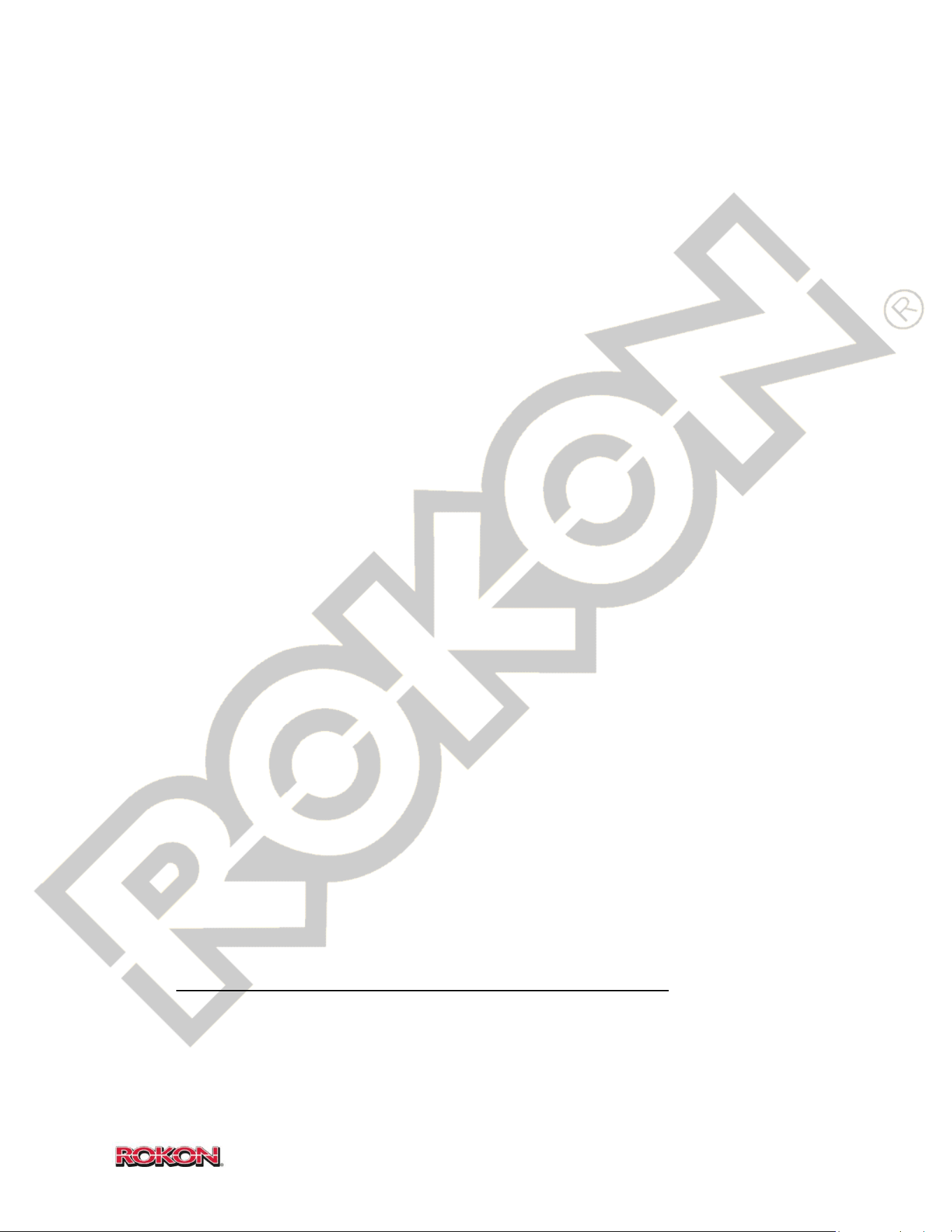
50
©2019 Rokon International Inc. Printed in U.S.A. ROKON® and its logo are registered trademarks
*Causes listed in order of probability
Symptom: Fails to stay on sprocket (derailment)
- Sprockets misaligned (see DRIVE CHAIN ADJUSTMENT in section 14)
- Loose axle bolt has caused chain to tighten or loosen beyond adjustment position
- Foreign material stuck in sprocket grooves or between chain rollers
- Lack of lubrication or improper chain lubricant applied
- Chain requires the removal of a link
- Chain is worn beyond use and requires replacement
- Miter box or gear box mounting hardware loose
- Sprocket is bent or has damaged teeth
Symptom: Chain separates or breaks
- Lack of lubrication or improper chain lubricant applied
- Foreign material stuck in sprocket grooves or between chain rollers
- Master link has failed and requires replacement
- Chain is worn beyond use and requires replacement
- Sprocket is bent or has damaged teeth
Symptom: Chains rusty or dry
- Lack of lubrication or improper chain lubricant applied
CVT SYSTEM (CLUTCH, BELT AND REAR PULLEY)
Symptom: Loose belt
- Belt worn and in need of replacement
- Secondary pulley has failed to close completely
- Engine has moved out of position and requires readjustment / alignment
Symptom: Tight belt
- Primary pulley has failed to fully disengage
- Engine has moved out of position and requires readjustment / alignment
Symptom: Dark residue or buildup on friction faces of pulley(s)
- Belt is being overheated by misuse or by selecting the improper speed range
- Excessive moisture or contaminants present on belt surface
- Belt worn and in need of replacement
Symptom: Burning rubber or plastic smell
- Belt is being overheated by misuse or by selecting the improper speed range
- Primary pulley is being overheated by misuse or by selecting the improper speed range
- Excessive moisture or contaminants present on belt surface
- Belt worn and in need of replacement
- Drive line failure is creating additional load on CVT system (see TRANSMISSION AND DRIVELINE)
- Secondary pulley has failed to close completely
Symptom: Chattering or clicking sound emitted by primary drive pulley
- Chattering or clicking noise is normal as pulley approaches engagement speed
- Foreign objects, dirt or debris inside primary pulley
- Chattering or clicking throughout power band indicates failure of internal components on primary pulley
- Primary pulley ramp plate retaining hardware loose

51
©2019 Rokon International Inc. Printed in U.S.A. ROKON® and its logo are registered trademarks
Symptom: Squealing *Causes listed in order of probability
- Belt is being overheated by misuse or by selecting the improper speed range
- Excessive moisture or contaminants present on belt surface
- Belt worn and in need of replacement
- Primary pulley has failed to fully engage
- Drive line failure is creating additional load on CVT system (see TRANSMISSION AND DRIVELINE)
- Secondary pulley has failed to close completely
Symptom: Primary pulley fails to fully engage
- Foreign objects, dirt or debris inside primary pulley
- Failure of internal components on primary pulley
- Primary is unable to fully engage under load due to misuse or by selecting the improper speed range
- Secondary pulley has failed to open completely
Symptom: Secondary fails to open fully
- Foreign objects, dirt or debris inside secondary pulley
- Failure of main bushing on secondary pulley
- Secondary is unable to fully engage under load due to misuse or by selecting the improper speed range
- Primary pulley has failed to fully engage
Symptom: Belt is spinning too fast while at idle
- Idle is set too high (see IDLE ADJUSTMENT in section 14)
- Idler bearing on primary pulley is stuck, contaminated with debris or has failed
- Engine has moved out of position and requires readjustment / alignment
- Primary pulley is stuck in engagement position and not releasing the belt
Symptom: Belt wears unevenly
- Belt is being overheated by misuse or by selecting the improper speed range
- Excessive moisture or contaminants present on belt surface
- Engine has moved out of position and requires readjustment / alignment
Symptom: Ineffective or decreased performance after fording/floating
- Belt is wet, allow time to dry
- Excessive contaminants present on belt surface
- Foreign objects, dirt or debris inside pulleys
BRAKES
Symptom: Excessive or irregular noise
- Foreign contaminants, debris or moisture on brake puck surface
- Brake disc is not moving freely on shaft or key
- Flash rust or corrosion on brake disc
- Brake pucks worn and in need of replacement
- Brake caliper is not disengaging completely
Symptom: Lacking brake lever pressure (spongey)
- Air in brake system; bleed according to procedure outlined in section 14
- Caliper piston is open and needs to be pumped back to closed position (pump brake lever)
- Fluid is leaking from the system or a bleeder screw is open
- Brake fluid level is low
- Brake pucks are worn and in need of replacement
- Faulty brake caliper
- Faulty master cylinder

52
©2019 Rokon International Inc. Printed in U.S.A. ROKON® and its logo are registered trademarks
*Causes listed in order of probability
Symptom: Front brake ineffective
- Air in brake system; bleed according to procedure outlined in section 14
- Fluid is leaking from the system
- Brake fluid level is low
- Brake pucks are worn and in need of replacement
- A bleeder screw is open
- Faulty brake caliper
- Faulty master cylinder
- Broken shear pin on front output shaft
Symptom: Rear brake ineffective
- Air in brake system; bleed according to procedure outlined in section 14
- Fluid is leaking from the system
- Brake fluid level is low
- Brake pucks are worn and in need of replacement
- A bleeder screw is open
- Faulty brake caliper
- Faulty master cylinder
- Broken shear pin on rear output sprocket
Symptom: Locked up (bike will not move when pushed or is hard to push)
- Brake disc is not moving freely on shaft or key
- Foreign contaminants, debris or moisture on brake puck surface
- Brake pucks have broken or fallen out of place
- Faulty brake caliper
- Faulty master cylinder
- Drive line failure (see TRANSMISSION AND DRIVELINE)
Symptom: Disc will not move freely on shaft
- Flash rust or corrosion on brake disc
- Lack of lubrication has seized brake disc to the shaft (lubricate with anti-seize)
- Shaft or key is corroded or damaged
Symptom: Pulsation feedback is present in brake lever
- Flash rust or corrosion on brake disc
- Foreign contaminants, debris or moisture on brake disc surface
- Brake disc is not moving freely on shaft or key
- Worn or warped brake disc
Symptom: Leaking caliper
- A bleeder screw is open
- Faulty bleeder screw
- Piston O-ring has deteriorated or has failed
Symptom: Leaking hose or fitting
- Loose fitting
- Bronze sealing washer (at master cylinder) has deteriorated or has failed
- Thread sealant (at caliper) has deteriorated or has failed
- Fitting has failed
- Hose has been punctured, has become deteriorated or has failed

53
©2019 Rokon International Inc. Printed in U.S.A. ROKON® and its logo are registered trademarks
Symptom: Leaking master cylinder *Causes listed in order of probability
- Reservoir is over-filled with brake fluid
- Reservoir cap is not fully tightened
- Diaphragm has deteriorated or has failed
- O-ring at master cylinder reservoir has deteriorated or has failed
- Faulty master cylinder
Symptom: Deteriorated master cylinder diaphragm
- Poor quality or incorrect grade brake fluid
- Dirty or contaminated brake fluid
ELECTRICAL AND IGNITION SYSTEM (See also KOHLER CH270 manual)
Symptom: No electrical voltage (key “on” or “off”)
- Battery dead
- Blown fuse
- Battery disconnected
- Fault caused by exposed or disconnected wire
Symptom: Low electrical voltage
- Battery is not sufficiently charged
- Battery is not holding a sufficient charge
- Battery is not receiving a proper charge from the stator or voltage regulator
Symptom: Continually blowing fuses
- Incorrectly rated fuse installed
- Accessory plugged into power point (if equipped) exceeds the amperage demand of the fuse
- User installed aftermarket accessory (if equipped) exceeds the amperage demand of the fuse
- Fault caused by a failed or malfunctioning electrical component (lights, starter, key switch, accessory)
- Fault caused by exposed or disconnected wire
Symptom: Battery will not hold charge
- Battery is old or defective
- Parasitic discharge, caused by exposed wire or accessory that has a full time electrical draw
- Not receiving proper voltage output from regulator
- Not receiving proper voltage output from the stator
Symptom: Battery will hold an external charge but is not being recharged by bike
- Blown fuse
- Poor battery ground
- Not receiving proper voltage output from regulator
- Not receiving proper voltage output from the stator
Symptom: Nothing happens when key is rotated to “Start” position
- Battery is not sufficiently charged or is dead
- Blown fuse
- Fault caused by exposed or disconnected wire
- Faulty ignition switch
- Faulty starter relay
- Faulty starter
- Engine will not rotate (see ENGINE)

54
©2019 Rokon International Inc. Printed in U.S.A. ROKON® and its logo are registered trademarks
Symptom: Electric starter slow or fails to start engine *Causes listed in order of probability
- Battery is not sufficiently charged
- Battery is old or defective
- Faulty starter
- Engine is not rotating freely (see ENGINE)
Symptom: Headlight inoperable
- Blown fuse
- Battery dead
- Key switch is not in the “on” position
- Defective headlight bulb
- Poor main harness ground
- Defective headlight switch
- Defective key switch
- Fault caused by exposed or disconnected wire
Symptom: Tail/Marker light inoperable
- Blown fuse
- Battery dead
- Key switch is in the”off” position
- Defective taillight bulb
- Poor tail light ground
- Defective headlight switch
- Defective key switch
- Fault caused by exposed or disconnected wire
Symptom: Brake light does not illuminate when levers are squeezed
- Defective taillight bulb
- Poor tail light
- Defective brake light switch
- Fault caused by exposed or disconnected wire
Symptom: Pressing kill button and/or rotating key to the “off” position fails to shut engine off
- Poor main harness ground
- Poor engine harness ground
- Fault caused by exposed or disconnected wire
- Defective handlebar kill button
- Defective street legal multifunction switch (if equipped)
- Defective key switch
Symptom: Turn signals fail to flash or flash erratically (Street legal)
- Faulty flasher unit
- Defective turn signal bulb
- Incorrect turn signal bulb installed
- Poor main harness ground
- Fault caused by exposed or disconnected wire
- Defective street legal multifunction switch
Symptom: Horn inoperable or emits irregular sound (Street legal)
- Body of horn is contacting structure of bike and preventing proper sound emittance
- Horn power lead is exposed or disconnected
- Poor main harness ground
- Defective horn
- Defective street legal multifunction switch

55
©2019 Rokon International Inc. Printed in U.S.A. ROKON® and its logo are registered trademarks
*Causes listed in order of probability
Symptom: Speedometer inoperable or is not reading correct speed (Street legal)
* For additional speedometer troubleshooting, refer to speedometer directions in manual packet
- Blown fuse
- Pickup sensor requires adjustment
- Dirt or debris on pickup sensor
- Damaged or disconnected sensor cable
- Poor main harness ground
- Exposed or disconnected speedometer full time power lead
- Exposed or disconnected speedometer switched power lead
- Defective pickup sensor
- Defective speedometer
Symptom: Power point inoperable (Optional)
- Key switch is in the “off” position
- Blown fuse
- Device or accessory inoperative
- Fault caused by exposed or disconnected wire
- Poor power point ground
- Moisture or debris inside power point is preventing good contact
- Defective power point
Symptom: Tach/Hour meter displaying erratic or inconsistent RPMs (Optional)
- Fault caused by exposed or disconnected wire
- Poor tach/hourmeter ground
- Weak or inconsistent ignition spark
- Incorrect or faulty tach/hourmeter
Symptom: Weak, inconsistent or no ignition spark
- Key switch is in the “off” position
- If street legal, headlight switch is not in the P or H position
- Fouled or dirty spark plug
- Spark plug gap incorrect (see section 14)
- Spark plug is worn and in need of replacement
- Deteriorated spark plug boot
- Poor contact between ignition wire and spark plug
- Deteriorated ignition wire
- Fault caused by exposed or disconnected wire (kill switch wires, tach/hourmeter wire)
- Ignition coil air gap is set incorrectly
- Defective ignition coil
- Defective handlebar kill button
- Defective street legal multifunction switch
- Defective or broken flywheel ignition magnet
HANDLING AND PERFORMANCE
Symptom: Bike bucks or hesitates
- Front tire pressure is lower than the rear (see section 14 for correct tire pressure settings)
- Defective or worn slip joint
- Engine problem (see ENGINE)
- CVT system problem (see CVT SYSTEM)
- Transmission or driveline problem (see TRANSMISSION AND DRIVELINE)

56
©2019 Rokon International Inc. Printed in U.S.A. ROKON® and its logo are registered trademarks
Symptom: Bike pulls to the right or left at speed *Causes listed in order of probability
- Tire pressure is set too low (see section 14 for correct tire pressure settings)
- Axle is adjusted too far to the left or right
Symptom: Steering feels hard or sticks
- Universal joint is failing to move smoothly on the main drive shaft (must slide freely in and out)
- Defective or worn slip joint (see also TRANSMISSION AND DRIVELINE)
- Damaged or worn steering head bearing
Symptom: Steering does not seem to reach its maximum angle (left or right)
- Wires, hoses or control cables are being pinched between fuel tank and front end
- Damaged or worn steering head bearing
- Universal joint is failing to move smoothly on the main drive shaft (must slide freely in and out)
Symptom: Suspension seems too stiff/too soft
- Shocks should be adjusted to suit rider comfort
- Inappropriate tire pressure set for riding conditions
Symptom: Left/Right vibration in handlebars while riding at speed
- Inappropriate tire pressure set for riding conditions
- Imbalanced tire
- Chain problem (see CHAIN DRIVE)
- Front drive problem (see MITER BOX AND UNIVERSAL JOINT)
- Tire is worn and in need of replacement
- Tire is not fully seated on rim
Symptom: Up/Down vibration while riding at speed
- Inappropriate tire pressure set for riding conditions
- Imbalanced tire
- Chain problem (see CHAIN DRIVE)
- Transmission or driveline problem (see TRANSMISSION AND DRIVELINE)
- Tire is worn and in need of replacement
- Tire is not fully seated on rim

57
©2019 Rokon International Inc. Printed in U.S.A. ROKON® and its logo are registered trademarks
16. COMPONENT REMOVAL / INSTALLATION GUIDE
Please refer to the warranty information in sections 19 and 20 prior to removing components.
FUEL TANK (please see health and safety information before attempting this procedure)
Removal
1. Move fuel tank valve to the “off’ position
2. Disconnect fuel line from the fuel tank valve (use a rag or container to catch any fuel that remains in the
fuel line).
3. Remove fuel tank retaining bolt (top of fuel tank, ¾” bolt head) and washers.
4. Gently remove fuel tank from bike, avoid pinching wires or cables against front end.
OPERATOR SEAT/SHOCK
Removal
1. Remove forward 9/16” retaining bolts connecting seat plate to frame on either side.
2. Remove 7/16” retaining nuts connecting lower seat shock mount to frame. (on “retro-seat” equipped
bikes, remove rear mounting bolt from left side mounting tab).
3. Carefully remove seat and shock assembly from bike.
PASSENGER SEAT
Removal
1. Remove four 7/16” retaining bolts from underside of seat (forward-left bolt may require a thin open-
ended 7/16” wrench).
2. Remove seat from bike
WHEELS/TIRES
Removal
1. Ensure that bike is in Neutral
2. Raise and secure the bike using an ATV jack so that both tires are completely off the ground.
3. Loosen drive chain (see chain adjustment procedure in section 14).
4. Locate and remove master-link from drive chain using a narrow flat head screw driver.
5. Remove drive chain from sprockets
6. Loosen axle retaining bolts and carefully remove wheel/tire assembly from bike.
Installation
1. Unscrew axle retaining bolts so that a sufficient amount of space exists between outside washer/spacer
and axle edge.
2. Install wheel/tire assembly in place sliding axle retaining bolts into mounting forks.
3. Using two 9/16” wrenches, snug both axle bolts simultaneously (do not tighten fully).
4. Reinstall chain over sprockets and reconnect ends using master-link.
5. Follow chain adjustment and sprocket alignment procedure outlined in section 14.
CVT PULLEYS
Forward pulley (clutch) removal
1. Remove belt using procedure outlined in section 14.
2. Remove ½” retaining bolt and locking tab.

58
©2019 Rokon International Inc. Printed in U.S.A. ROKON® and its logo are registered trademarks
3. Gently pull edges of fixed (inner) pulley face away from the engine. TIP (It may be necessary to pry
between fixed pulley face and engine block with a crowbar or large screwdriver. If this is required, avoid
the outer edge of the inner pulley face and instead try to pry from the hub).
4. Gently remove clutch from engine.
Installation
1. Clean engine crankshaft end and lubricate with anti-seize.
2. Install clutch on shaft.
3. Install retaining bolt, make sure locking tab is oriented properly and bend corners over bolt to prevent
rotation. (the use of a new locking tab is recommended)
4. Reinstall belt.
Rear Pulley removal
1. Remove belt using procedure outlined in section 14.
2. Loosen rear pulley set screws (3) around the hub using an Allen wrench.
3. Gently pull edges of movable (inner) pulley face away from the transmission. TIP (It may be necessary to
pry between the hub and the bike’s frame with a prybar or large screwdriver. If this is required, avoid the
outer edge of the inner pulley face and instead try to pry from the hub).
4. Gently remove rear pulley from transmission.
Installation
1. Clean transmission input shaft and lubricate with anti-seize.
2. Install rear pulley on shaft, seat to retaining ring.
3. Tighten rear pulley set screws (3) around the hub using an Allen wrench.
4. Reinstall belt.
MITER BOX
Removal
1. Unplug and remove headlight from front fender
2. Remove chain guard
3. Loosen front drive chain (see chain adjustment procedure in section 14)
4. Separate drive chain by removing the master-link and remove the chain from the sprockets.
5. Remove the brake caliper by first removing the two ½” bolts and lock nuts. Move caliper out of the way
NOTICE DO NOT disconnect brake line.
6. Remove brake disc by sliding it off of the shaft.
7. Remove the two miter box retaining bolts (1/2”) holding the miter box to the fork.
8. Gently slide the miter box and universal joint forward and out of the front end tube.
Installation
1. Align the universal joint key slot to the corresponding key on the main drive shaft.
TIP using a cardboard toilet paper roll around the universal joint during installation can aide the alignment
process; just be sure to remove it with a knife once the miter box has been properly installed.
2. Seat the miter box in place and reinstall the retaining bolts.
3. Clean and lubricate brake disc shaft with anti-seize and reinstall brake disc.
4. Reinstall brake caliper, pump brake lever to rebuild brake pressure before use.
5. Reinstall drive chain and connect ends using the master-link.
6. Adjust chains according to the procedure in section 14.
7. Reinstall chain guard.
8. Reinstall headlight.

59
©2019 Rokon International Inc. Printed in U.S.A. ROKON® and its logo are registered trademarks
TRANSMISSION
Removal
1. Place the transmission in 3
rd
range (all the way in).
2. Remove operator seat and shock (see OPERATOR SEAT/SHOCK) or rear cargo rack (if equipped).
3. Remove rear CVT pulley (see CVT PULLEYS).
4. Loosen rear chain (see chain adjustment procedure in section 14).
5. Move rear chain out of the way, support it against frame.
6. Rotate driveline so that the rear spring pin on the slip-joint is aligned with the rear spring pin hole. (see
slip-joint image in section 14 entitled ‘Over-running clutch lubrication’) TIP this can be accomplished by
rolling the bike forward or back until aligned.
7. Using a spring pin punch, drive the spring pin out of the slip joint from the top down.
8. Remove the 3 transmission retaining bolts from the frame mounting plate and the forward retaining bolt
from the upper gusset by the air cleaner (all ½” hardware).
9. Move brake caliper and bracket out of the way NOTICE DO NOT disconnect brake line.
10. Gently slide the transmission back and out of the main frame tube. TIP if the transmission does not slide
easily out of the main frame tube, a rubber mallet can be used to break it free. NOTICE DO NOT strike the
transmission case with a hard faced hammer.
11. Maneuver the transmission out of the frame. TIP place a towel or blanket on the rear fender to prevent
scratching or scuffing.
Installation
1. Place the transmission in 3
rd
range (all the way in).
2. Clean and lubricate brake disc shaft with anti-seize and reinstall brake disc.
3. Maneuver the transmission into place within the frame of the bike. TIP place a towel or blanket on the
rear fender to prevent scratching or scuffing.
4. Gently slide the transmission forward into the main frame tube ensuring that the forward output shaft
fully seats into the slip-joint boss.
5. Rotate driveline so that the rear spring pin hole on the slip-joint is aligned with the corresponding hole on
the transmissions forward output shaft. TIP this can be accomplished by rolling the bike forward or back
until aligned.
6. Using a spring pin punch, install the spring pin connecting the slip joint to the forward output shaft.
7. Position the brake caliper over the disc and align bracket holes with transmission mounting holes.
8. Reinstall the 3 transmission retaining bolts through the frame mounting plate and the forward retaining
bolt through the upper gusset by the air cleaner. Pump brake lever to rebuild brake pressure before use.
9. Reinstall drive chain and connect ends using the master-link. Readjust according to procedure outlined in
section 14.
10. Reinstall rear CVT pulley (see CVT PULLEYS).
11. Reinstall operator seat and shock.
DRIVELINE
Removal
1. Remove fuel tank (see FUEL TANK).
2. Remove operator seat (see OPERATOR SEAT)
3. Remove passenger seat (see PASSENGER SEAT).
4. Remove rear wheel (see WHEELS/TIRES).
5. Remove rear fender (see FENDERS).
6. Remove transmission (see TRANSMISSION).
7. Remove miter box (see MITER BOX).
8. Remove the two 7/16” carrier bearing retainer bolts from the frame (in front of the fuel tank post).
9. Slide the driveline out from the rear of the main frame tube.

60
©2019 Rokon International Inc. Printed in U.S.A. ROKON® and its logo are registered trademarks
TIP It is possible to remove the transmission and driveline as a single unit once the rear fender and wheel have
been removed.
Installation
1. Slide driveline into the rear of the main frame tube.
2. Align the carrier bearing block bolt holes with the corresponding holes in the main frame tube. TIP a small
screw driver or pick can be used to line up bolt holes.
3. Loosely install the two 7/16” carrier bearing retainer bolts DO NOT tighten yet.
4. Install transmission (see TRANSMISSION)
5. Tighten carrier bearing retainer bolts.
6. Install miter box (see MITER BOX).
7. Install rear fender.
8. Install rear wheel (see WHEELS/TIRES).
9. Install passenger seat.
10. Install operator seat.
11. Install fuel tank
BRAKES
Master Cylinder removal
1. Place the bike in an upright and level position
2. Remove the throttle grip, hand grip and any other accessories on the handlebar.
TIP Do not alter the position of the throttle end-play adjuster when removing the throttle grip.
3. Disconnect the brake light switch.
4. Separate the brake hose from the master cylinder by removing the 7/16” hose fitting. Use a rag to catch
any brake fluid that leaks from the hose or the brake fluid reservoir. Place the hose in an upright position
to prevent excessive fluid loss.
5. Remove the screw and retaining nut clamping the master cylinder to the handlebar.
6. Gently pry open the retaining clamp using a flat head screwdriver and slide the master cylinder assembly
off of the handlebar.
Installation
1. Gently pry open the retaining clamp using a flat head screwdriver and slide the master cylinder assembly
onto the handlebar.
2. Install the screw and retaining nut clamping the master cylinder to the handlebar.
3. Connect the brake hose to the master cylinder.
4. Perform brake bleeding procedure outlined in section 14.
5. Reinstall throttle grip, hand grips and any other accessories mounted to the handlebar.
Caliper removal
1. Grasp the brake disc and pull it towards the live side of the caliper (the side with the bleeder screws) to
open the caliper.
2. Note hardware orientation and remove the two ½” bolts and nuts holding the caliper to the front
end/brake bracket.
3. Slide the caliper off the disc and remove it from the bike.
4. Separate the brake hose from the caliper by removing the 7/16” hose fitting. Use a rag to catch any brake
fluid that leaks from the hose or the caliper. Place the hose in an upright position to prevent excessive
fluid loss.
5. If servicing brake pucks, use a narrow flat head screw driver to remove the brake puck retaining screws.
Installation
1. Connect the brake hose to the caliper.

61
©2019 Rokon International Inc. Printed in U.S.A. ROKON® and its logo are registered trademarks
2. Slide the caliper over the disc and line up the mounting holes with the bracket/front end holes.
3. Install the two ½” bolts, nuts and associated washers
4. Perform brake bleeding procedure outlined in section 14.
MUFFLER/EXHAUST PIPE
Removal
1. Loosen the two 10mm head pipe retaining bolts.
2. Remove the two ½” muffler retaining nuts from behind the muffler.
3. Lower the muffler from the retaining studs and slide the muffler assembly off of the head pipe and out of
the frame.
4. Remove the two 10mm head pipe retaining bolts.
5. Remove the head pipe from the engine.
Installation
1. Install the head pipe on the engine and loosely install the two 10mm head pipe retaining bolts (do not
tighten yet).
2. Insert the muffler assembly into the frame and slide the exhaust pipe over the head pipe.
3. Install the muffler mounting tabs onto the retaining studs and install the two 1/2” retaining nuts.
4. Completely tighten the 10mm head pipe retaining bolts.
FENDERS
Front Fender removal
1. Disconnect and remove the headlight.
2. Remove the 3 fender retaining screws/nuts from the front end.
3. Remove the fender from the front end.
Rear Fender removal
1. Remove the rear wheel (see WHEELS/TIRES)
2. Remove the muffler assembly (see MUFFLER/EXHAUST PIPE)
3. Remove the passenger seat (see PASSENGER SEAT)
4. Remove the two muffler mounting bolts and nuts.
5. Remove the six fender retaining screws and nuts.
6. Remove the fender from the bike.
Installation
1. Line the fender up with the mounting holes in the frame.
2. Install the six fender mounting screws and nuts.
3. Install the two muffler mounting bolts and nuts.
4. Install the passenger seat.
5. Install the muffler assembly (see MUFFLER/EXHAUST PIPE).
7. Install the rear wheel (see WHEELS/TIRES).
CARBURETOR/INTAKE PASSAGE
(Please see health and safety information before attempting this procedure)
Removal
1. Move both fuel valves to the “Off” position.
2. Remove the air cleaner cover and air filter (see section 13).
3. Remove the carburetor cover (see section 13).
4. Using a 13mm socket, remove the two carburetor/intake passage retaining nuts.

62
©2019 Rokon International Inc. Printed in U.S.A. ROKON® and its logo are registered trademarks
5. Remove the intake passage. TIP separate the PCV ventilation hose from the intake housing instead of the
valve cover, this makes reinstallation much easier.
6. Separate the fuel line from the carburetor fuel inlet nipple. Use a rag to catch any fuel that remains in the
fuel line.
7. Note the position of the throttle cable clamp on the throttle cable and loosen the clamp screw.
8. Remove the throttle cable from the cable clamp and pull it through the throttle arm.
9. Remove the carburetor from the engine.
Installation
1. Install the carburetor onto the intake mounting studs. Ensure that all gaskets are present, clean and
properly oriented. Ensure that choke lever is present an in its proper position.
2. Insert the throttle cable through the return spring and the throttle arm hole.
3. Insert the throttle cable through the retaining clamp ensuring that it is positioned where it was prior to
removal.
4. Tighten the cable clamp screw.
5. Check throttle end-play, adjust if necessary (see end-play adjustment procedure outlined in section 14).
6. Install the fuel line over the fuel inlet nipple.
7. Install the intake passage; be sure to reconnect the PCV hose.
8. Install the two 13mm retaining nuts.
9. Install the carburetor cover.
10. Install the air filter and air cleaner cover.
PULL STARTER/COOLING DUCT
Pull starter removal
1. Remove the 3 8mm pull starter bolts.
2. Remove the pull starter assembly.
Cooling duct removal
1. Remove the carburetor cover (see section 13).
2. Remove the two 10mm bolts from the bottom of the cooling duct housing.
3. Remove the two 10mm nuts from the top of the cooling duct housing.
4. Remove the cooling duct housing.
FLYWHEEL (see also KOHLER CH270 Manual)
Removal
1. Remove the cooling duct (see PULL STARTER/COOLING DUCT)
2. Remove the flywheel retaining nut, pull starter cup and cooling fins.
3. Note the position of the ignition coil and remove the two 10mm ignition coil retaining bolts. Remove the
ignition coil.
4. Use a puller to separate the flywheel from the crankshaft.
5. Remove the flywheel.
Installation
1. Install the flywheel onto the crankshaft.
2. Install the cooling fins, pull starter cup and flywheel retaining nut.
3. Torque flywheel nut to 655 In-lbs.
4. Install the ignition coil, set air gap to .010.
5. Install the cooling duct/pull starter.

63
©2019 Rokon International Inc. Printed in U.S.A. ROKON® and its logo are registered trademarks
ELECTRIC STARTER
Removal
1. Disconnect the negative battery terminal from the battery.
2. Disconnect the positive battery lead and control wire from starter relay.
3. Remove the cooling duct (see PULL STARTER/COOLING DUCT)
4. Remove the flywheel (see FLYWHEEL)
5. Remove the 2 10mm electric starter mounting bolts.
6. Remove the starter.
HANDLEBARS
Removal
1. Remove/disconnect throttle grip.
2. Remove/disconnect brake master cylinders (see BRAKES).
3. Remove/disconnect kill/headlight switch (see ELECTRICAL COMPONENTS)
4. Disconnect the brake light switches from master cylinders.
5. Remove the two handlebar-to-fork mounting bolts. (rearmost bolts that thread into the fork tubes)
6. Remove handlebar from front end.
FRONT END (Autograb and Standard)
Removal
1. Remove front wheel (see WHEELS/TIRES).
2. Remove front fender (see FENDERS).
3. Remove front brake caliper (see BRAKES).
4. Remove miter box (see MITER BOX).
5. Remove handlebars (see HANDLEBARS).
6. Remove the two 1 1/8” front end mounting bolts.
7. Remove the front end from the bike.
Installation
1. Line the front end steering bearings up with the holes in the steering head.
2. Install the two 1 1/8” front end mounting bolts, torque to 200 ft-lbs.
3. Install handlebars.
4. Install miter box (see MITER BOX).
5. Install front brake caliper (see BRAKES)
6. Install front fender.
7. Install front wheel. (see WHEELS/TIRES)
ELECTRICAL COMPONENTS
(Disconnect negative battery lead prior to performing these procedures)
Headlight removal
1. Disconnect electrical leads.
2. Remove mounting nut from stud.
3. Remove headlight.
Tail light removal
1. Disconnect electrical leads.
2. Remove mounting screws/nuts.
3. Remove tail light assembly.

64
©2019 Rokon International Inc. Printed in U.S.A. ROKON® and its logo are registered trademarks
Headlight/kill switch removal
1. Remove Philips head screw from retainer clamp.
2. Separate retaining clamps from housing.
3. Open housing and loosen cable retaining screws.
4. Remove wires from switch assembly.
Key/Ignition switch removal
1. Remove battery cover, disconnect negative battery lead.
2. Remove key from switch.
3. Remove CVT housing cover (see section 13).
4. Disconnect main engine electrical harness from back of switch, remove ground plug.
5. Remove switch retaining nut and lock washer from key switch housing.
6. Remove key switch from bike.
Voltage Regulator removal
1. Remove the electrical access cover (see section 13).
2. Disconnect the two A/C leads from the outer terminals.
3. Disconnect the D/C lead from the center terminal.
4. Remove the two 7/16” voltage regulator retaining bolts.
5. Remove voltage regulator.
Stator removal (see also KOHLER CH270 Manual)
1. Remove cooling duct (see PULLSTARTER/COOLING DUCT)
2. Remove flywheel (see FLYWHEEL)
3. Disconnect two A/C leads from outer terminals on voltage regulator.
4. Remove the four 10mm stator retaining bolts.
5. Remove the stator.
Main Harness removal
1. Remove fuel tank (see FUEL TANK)
2. Remove operator seat (see OPERATOR SEAT)
3. Remove passenger seat (see PASSENGER SEAT)
4. Loosen miter box mounting bolts and slide miter box forward (see MITER BOX)
5. Disconnect brake switch leads.
6. Disconnect headlight/kill switch leads.
7. Disconnect headlight leads, slide headlight leads out from between fork and miter box.
8. Disconnect tail light leads.
9. Disconnect main power lead (below fuel tank).
10. Disconnect main ground lead (by air cleaner).
11. Cut any zip ties retaining harness to the frame and remove the main harness.
Power Point removal (if equipped)
1. Remove electrical access cover (see section 13).
2. Disconnect power leads to power point.
3. Remove plastic retaining nut on back of power point.
4. Remove power point.

65
©2019 Rokon International Inc. Printed in U.S.A. ROKON® and its logo are registered trademarks
17. ILLUSTRATED PARTS GUIDE
INDEX OF ILLUSTRATIONS
SECTION PAGE NOMENCLATURE
17-1 66 Chain/Links
17-2 67 Decals
17-3 68 Electrical
17-4 69 Street Legal Components
17-5 71 Engine and components
17-6 74 Frame and components
17-7 76 Standard Front Fork (Scout)
17-8 77 Autograb Front Fork (Trail-Breaker and Ranger)
17-9 79 Front Cargo Rack
17-10 80 Fuel Tank
17-11 81 Exhaust system
17-12 82 Handlebars and Brakes
17-13 84 Brake Caliper
17-14 85 Operator Seat
17-15 86 Passenger Seat
17-16 87 CVT Drive Pulley (Clutch)
17-17 88 CVT Driven Pulley (Rear Pulley)
17-18 89 Transmission External
17-19 90 Transmission Internal
17-20 93 Miter Box
17-21 94 Driveline
17-22 95 Wheel (Aluminum Drum)
17-23 96 Wheel (Steel Spoke)
17-24 97 Tow Bars
17-25 98 Rear Cargo Rack
17-26 99 Sidecar
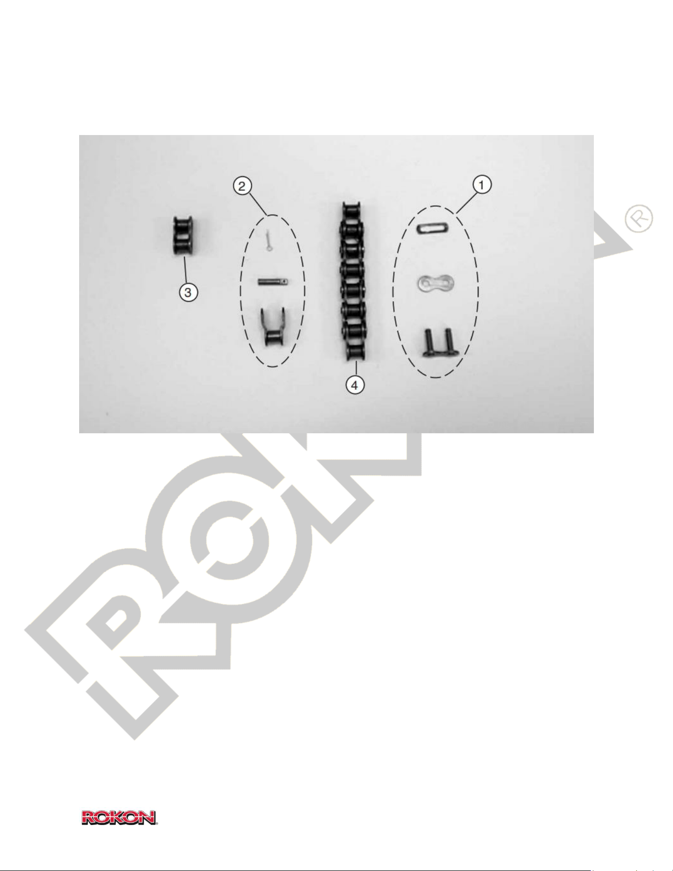
66
©2019 Rokon International Inc. Printed in U.S.A. ROKON® and its logo are registered trademarks
17-1 CHAIN/LINKS
ITEM PART NUMBER DESCRIPTION QTY
1 100356 Master Link 2 - 3
2 100355 Offset Link AS NEEDED
3 100354 Full Link AS NEEDED
4 108984 Chain Length AS NEEDED
NS 101568A Front Chain 107P 1 (Scout Only)
NS 101570A Rear Chain 117P 1
NS 108946 Chain, Horizontal 1 (Autograb)
NS 108947 Chain, Vertical 1 (Autograb)
NS 101576 Chain, Ranger Rear 119P 1
NS 101575 Chain, Ranger Vertical 1
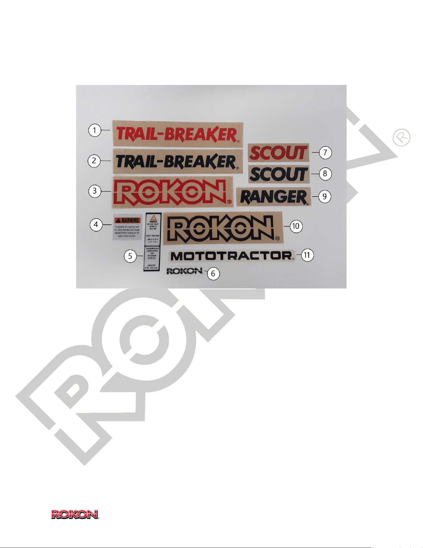
67
©2019 Rokon International Inc. Printed in U.S.A. ROKON® and its logo are registered trademarks
17-2 DECALS
ITEM PART NUMBER DESCRIPTION QTY
1 108040 Decal, TRAIL-BREAKER in Red 2
2 108039 Decal, TRAIL-BREAKER in Black 2
3 108044 Decal, ROKON in Red 2
4 108988 Decal, Oil Warning 1
5 101626 Decal, Shift Instructions 1
6 108972 Decal, Handlebar, ROKON 1
7 108043 Decal, SCOUT in Red 2
8 101595 Decal, SCOUT in Black 2
9 108041 Decal, RANGER in Black 2
10 108045 Decal, ROKON in Black 2
11 103138 Decal, MOTOTRACTOR 2
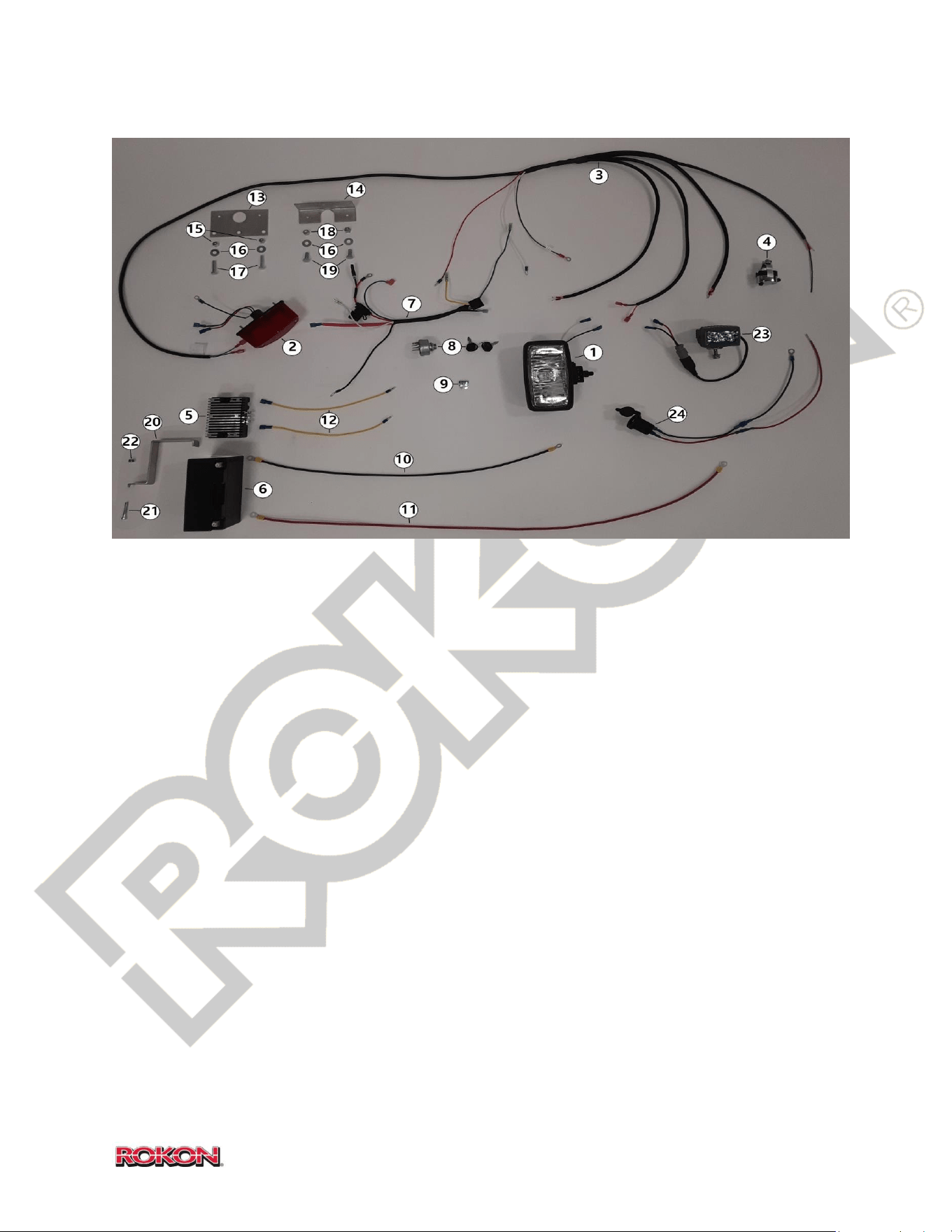
68
©2019 Rokon International Inc. Printed in U.S.A. ROKON® and its logo are registered trademarks
17-3 ELECTRICAL
ITEM PART NUMBER DESCRIPTION QTY
1 104313 Head Light 1
2 104315 Tail Light 1
3 108179 Wiring Harness 7HP 1
4 100191 Kill Button & Headlight On/Off 1
5 108126 Voltage Regulator 1
6 MK7BBS Battery AGM 1
7 KOH1717618-S 7HP Engine Harness 1
8 KOH2509937-S Ignition Switch (Includes Keys) 1
9 KOH 33-034 Fuse, 25 Amp 1
10 120023 Battery Lead, Negative 1
11 120022 Battery Lead, Positive 1
12 120024 Lead, Voltage regulator 2
13 101135 Tail Light Bracket 1
14 101136 Tail Light Bracket, Cargo Rack 1
15 100169 Lock Nut 2
16 100255 Washer 2
17 100170A Bolt 2
18 100551 Lock Nut 2
19 100848 Bolt 2
20 108274 Battery Hold-Down 1
21 108963 Bolt, 10 – 32 x 1 ¼ 1
22 100037 Lock Nut, 10 – 32 1
23 108920 LED Headlight (Optional)
24 109009 Power Point (Optional)
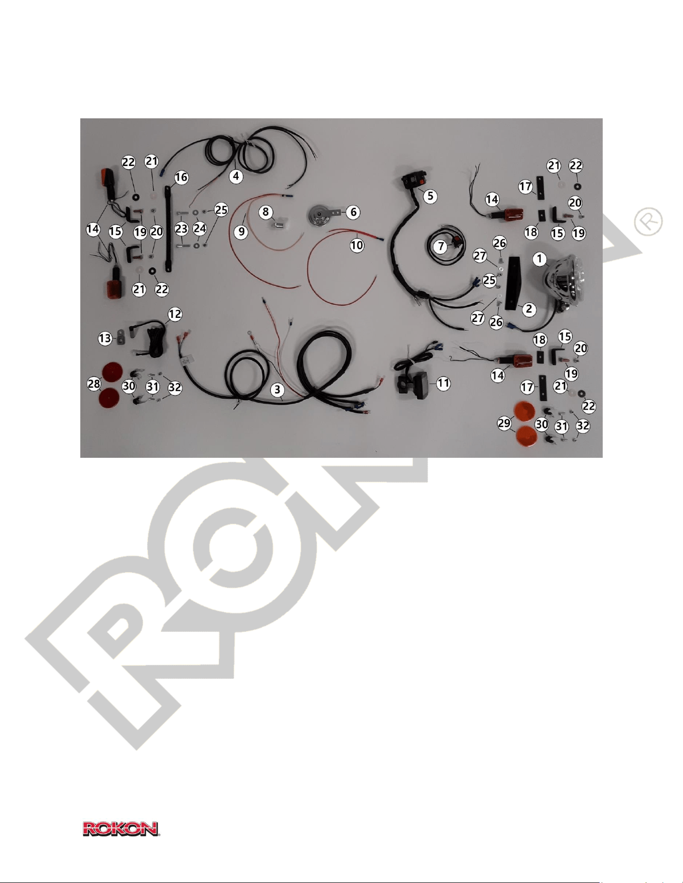
69
©2019 Rokon International Inc. Printed in U.S.A. ROKON® and its logo are registered trademarks
17-4 STREET LEGAL COMPONENTS (RANGER ONLY)
ITEM PART NUMBER DESCRIPTION QTY
1 104314 Head Light, Hi/Lo 1
2 104317 Bracket, Hi/Lo Head Light 1
3 104318 Wiring Harness, 7HP Ranger 1
4 104319 Turn Signal Harness, Ranger 1
5 KS12-0050 Street Legal Multifunction Switch 1
6 108971 Horn 1
7 EM46-50430 Kill Button, Right Side 1
8 FLA552 Flasher Unit 1
9 104320 Harness, Flasher 1
10 104321 Harness, Speedometer/Horn 1
*Continued

70
©2019 Rokon International Inc. Printed in U.S.A. ROKON® and its logo are registered trademarks
17-4 (Continued)
ITEM PART NUMBER DESCRIPTION QTY
11 103191 Speedometer/Odometer 1
12 103193 Speedometer/Odometer Sensor 1
13 103194 Speedometer Sensor Bracket 1
14 108942 Turn Signal Light (set of 2) 2
15 103195 Turn Signal Mount 4
16 103196 Rear Turn Signal Bracket 1
17 103197 Front Turn Signal Bracket, Lower 2
18 103198 Front Turn Signal Bracket, Upper 2
19 100038 Bolt, 5/16-18 4
20 100171 Lock Nut, 5/16-18 4
21 103199 Washer, Nylon 4
22 103200 Washer, Spring 4
23 100170 Bolt, ¼-28 x 1 ½ 2
24 100255 Washer, Flat 2
25 100169 Lock Nut, ¼-28 4
26 100167 Bolt, ¼-28 x ½ 2
27 100165 Washer, Flat 2
28 108975 Reflector, Red (set of 2) 1
29 108976 Reflector, Amber (set of 2) 1
30 FAS SPN CLAMP 11/16 Reflector Mounting Clamp 4
31 108964 Cap Screw, 10-32 x ½ 4
32 100037 Lock Nut, 10-32 4
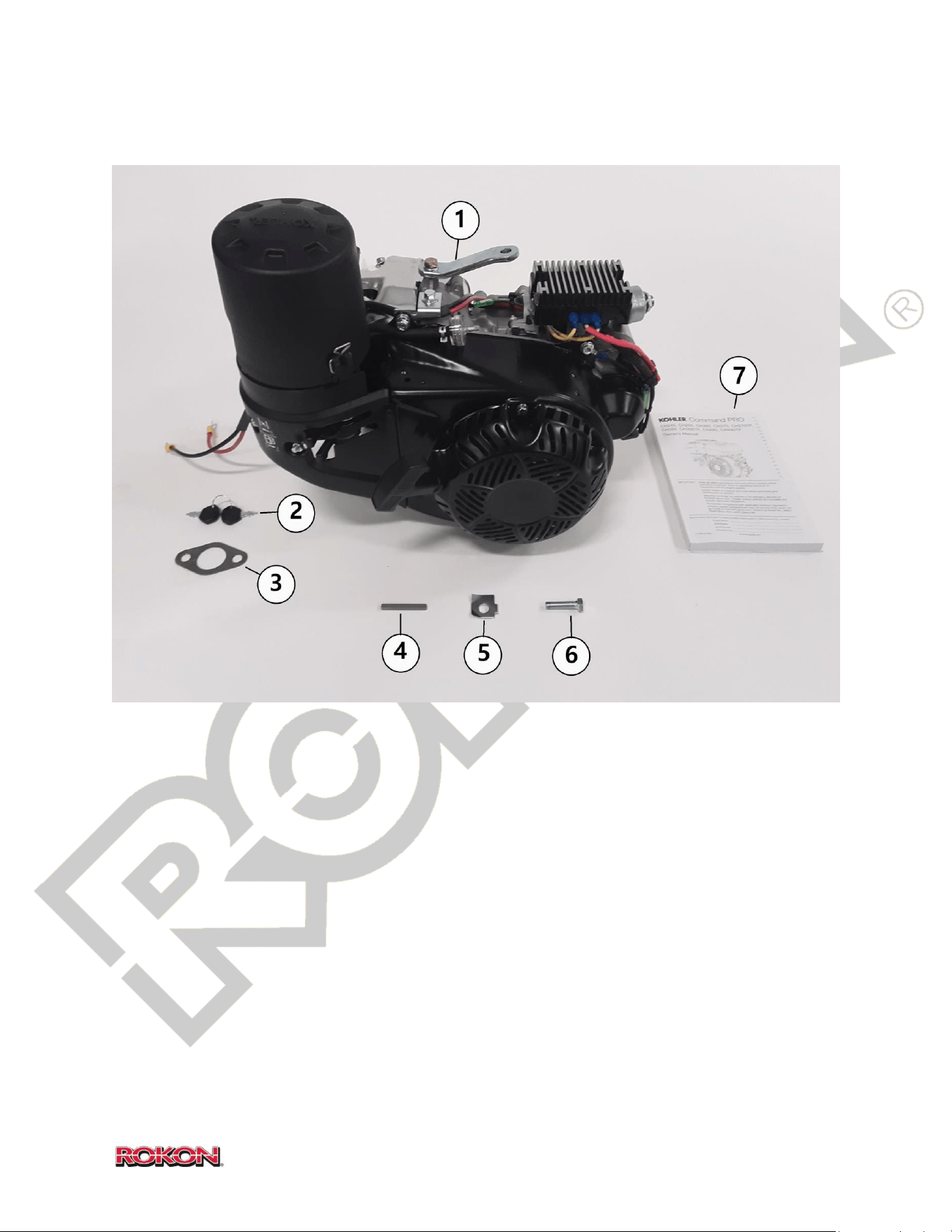
71
©2019 Rokon International Inc. Printed in U.S.A. ROKON® and its logo are registered trademarks
17-5 ENGINE AND COMPONENTS
ITEM PART NUMBER DESCRIPTION QTY
1 KOHCH270 7HP Engine Complete 1
2 KOH4834001-S1 Ignition Key (sold individually) 2
3 KOH1704103-S Exhaust Gasket 1
4 KOH1434001-S Key, Crank, 7HP 1
5 108983 Locking Clip 1
6 108123 Clutch Bolt 1
7 KOH7HPMAN 7HP Engine Manual 1
*Continued
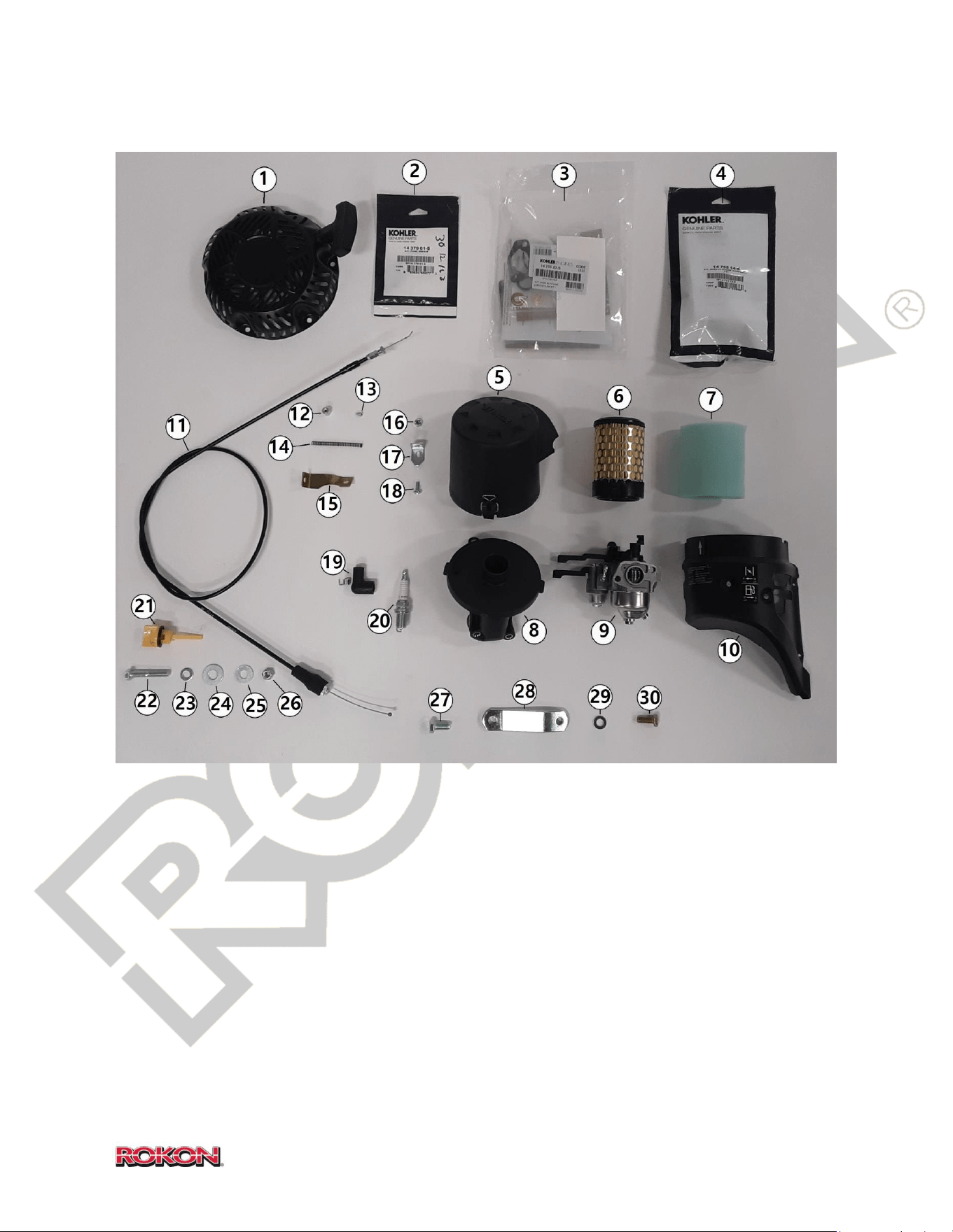
72
©2019 Rokon International Inc. Printed in U.S.A. ROKON® and its logo are registered trademarks
17-5 (Continued)
ITEM PART NUMBER DESCRIPTION QTY
1 KOH1716502-S 7HP Recoil Assembly 1
2 KOH1437901-S Pawl Repair Kit
3 KOH1475523-S Kit, High Altitude, 8K+
4 KOH1475514-S Kit, High Altitude, 4-8K
5 KOH1709641-S Air Filter Cover 1
6 KOH1708307-S Air Filter 1
7 KOH1708312-S Air Pre-Cleaner 1
*Continued

73
©2019 Rokon International Inc. Printed in U.S.A. ROKON® and its logo are registered trademarks
17-5 (Continued)
ITEM PART NUMBER DESCRIPTION QTY
8 KOH1709423-S Air Filter Base 1
9 KOH1785322-S Carburetor 7HP 1
10 KOH1709604-S Carburetor Cover 1
11 107037 Throttle Cable 7HP 1
12 110058 Cable Holder 7HP 1
13 100459 Screw, PH 6/32 x 1/4 1
14 100559 Throttle Spring 1
15 110054 Throttle Bracket 1
16 100037 Lock Nut, 10-32 1
17 108246 Air Filter Cover Retaining Tab 1
18 100034 Screw, PH 1
19 K-705-2 Sparky 1
20 100369K7 Spark Plug 7HP 1
21 KOH1703808-S Dipstick, 7HP 2
22 108967 Bolt, 8-1.25 4
23 108965 Washer, Flat 8mm 4
24 100208 Washer, Flat 3/8 8
25 100202 Washer, Flat 5/16 4
26 108966 Lock Nut, 8-1.25 4
27 100572 Bolt, 3/8-24 1
28 109000 Head Steady, Kohler 1
29 100255 Washer, Flat 1
30 108943 Bolt, Head steady 1
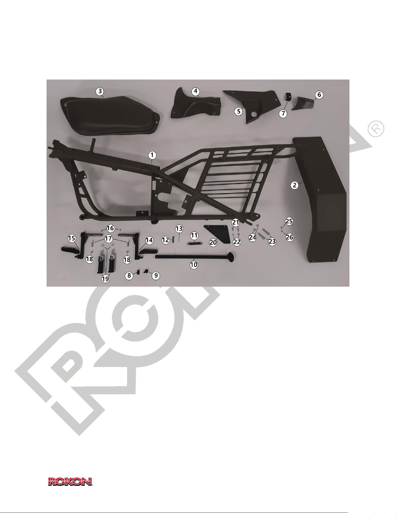
74
©2019 Rokon International Inc. Printed in U.S.A. ROKON® and its logo are registered trademarks
17-6 FRAME AND COMPONENTS
ITEM PART NUMBER DESCRIPTION QTY
1 105066 Frame Assembly Kohler 7HP 1
2 110049 Rear Fender Kohler 7HP 1
3 108994 Fairing, LHS 1
4 108995 Fairing, RHS Front 1
5 108996B Fairing, RHS Bottom 1
6 108996T Fairing, RHS Top 1
7 108927 RHS Top Fairing Mounting Tab 1
8 101630 Receptacle Nut, Fairing 7
9 101629 Mounting Bolt, Fairing 7
*Continued

75
©2019 Rokon International Inc. Printed in U.S.A. ROKON® and its logo are registered trademarks
17-6 (Continued)
ITEM PART NUMBER DESCRIPTION QTY
10 100386 Kickstand 1
11 100223 Kickstand Spring 1
12 100285 Clevis Pin, 5/16 x 1 3/8 1
13 100290 Cotter Pin, 1/8 x 3/4 1
14 108144A Foot Rest RHS Cleated 1
15 108146A Foot Rest LHS Cleated 1
16 108962 Screw, 10-32 x 1/4 2
17 108123 Bolt, 5/16 – 24 x 1 ½ 2
18 100551 Lock Nut, 5/16 – 24 2
19 100343 Passenger Foot Rest Assembly (set of 2) 1
20 101572 Rear Chain Guard 1
21 100126 Screw PH, ¼ - 20 x 5/8 2
22 100165 Washer, Flat 2
23 100573 Wheel Adjuster Bolt, 3/8 – 24 x 1 ¾ 2
24 100036 Nut, 3/8 – 24 Jam 2
25 100034 Fender Mounting Screw, PH 10 – 32 ¼ 6
26 100037 Fender mounting Lock Nut, 10- 32 6
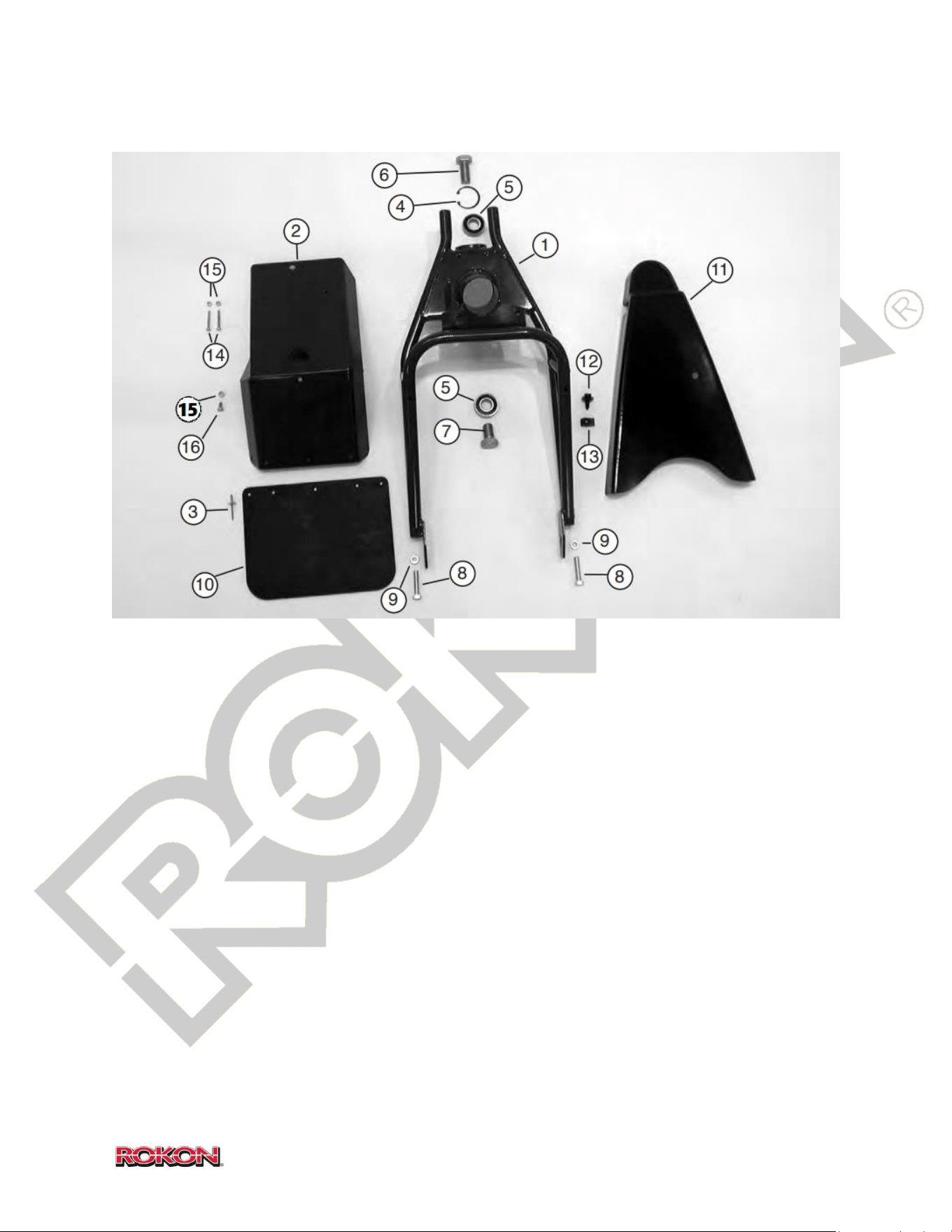
76
©2019 Rokon International Inc. Printed in U.S.A. ROKON® and its logo are registered trademarks
17-7 STANDARD FRONT FORK (SCOUT)
ITEM PART NUMBER DESCRIPTION QTY
1 107003A Front Fork 1
2 100453 Front Fender 1
3 100935 Pop Rivet 5
4 103136 Snap Ring 1
5 100772 Bearing 2
6 107026 Upper Fork Bolt 1
7 107025 Lower Fork Bolt 1
8 100573 Wheel Adjuster Bolt 3/8-24 x 1 ¾ 2
9 100036 Hex Nut Jam 3/8-24 2
10 100427 Front Mud Flap 1
11 108106 Front Chain Guard 1
12 101629 Mounting Bolt, Fairing 1
13 101630 Receptacle Nut, Fairing 1
14 108963 Screw, 10-32 x 1 ¼ 2
15 100037 Lock Nut, 10-32 3
16 100034 Screw, 10-32 x 1/2 1
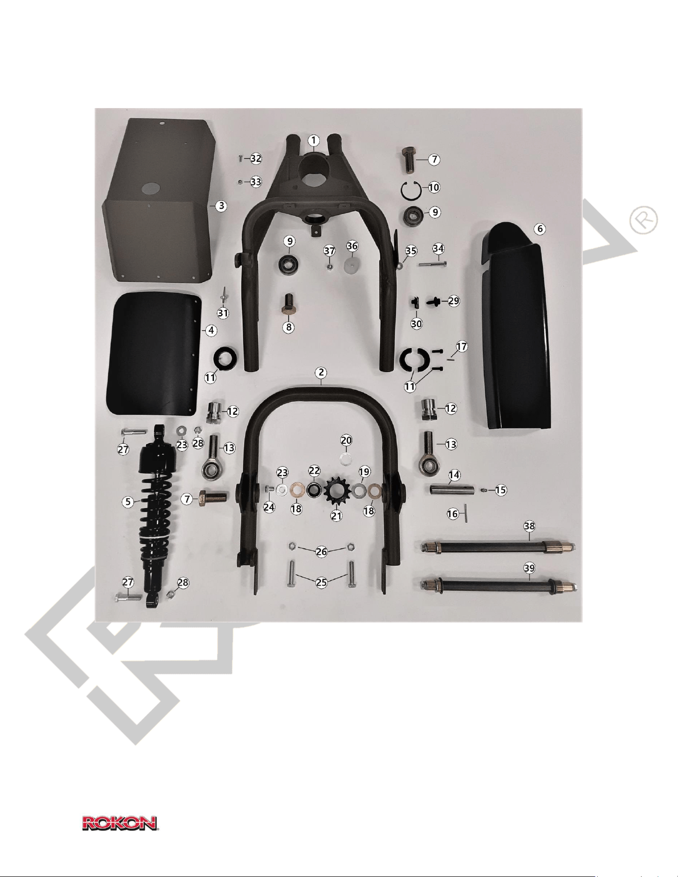
77
©2019 Rokon International Inc. Printed in U.S.A. ROKON® and its logo are registered trademarks
17-8 AUTOGRAB FRONT FORK (TRAIL-BREAKER AND RANGER)
ITEM PART NUMBER DESCRIPTION QTY
1 108303 Fork, Front Suspension 1
2 108311 Swing Arm Tube 1
3 100453 Front Fender 1
4 100427 Front Mud Flap 1
5 109002-S2 Shock absorber 1
6 108299 Front Chain Guard, Suspension 1
7 107026 Upper Fork/Swing Arm Bolt 2
8 107025 Lower Fork Bolt 1

78
©2019 Rokon International Inc. Printed in U.S.A. ROKON® and its logo are registered trademarks
17-8 (Continued)
ITEM PART NUMBER DESCRIPTION QTY
9 100772 Bearing 2
10 103136 Snap Ring 1
11 108320 Collar Clamp Assembly 2
12 108319 Adjuster Nut, Rod End 2
13 108335 Spherical Rod End 2
14 108309 Idler Shaft 1
15 108327 Grease Fitting 1
16 108322 Dowel Pin, 1/8 x 1 ½ 1
17 108321 Roll Pin, 1/8 x ½ 2
18 108336 Thrust Bearing 2
19 300080C Spacer 1
20 101615 Shim, ¾ ID x .005 AS NEEDED
21 108308 Double Sprocket 1
22 108323 Needle Bearing 1
23 100202 Washer, Flat 2
24 108326 Bolt, 3/8 – 24 x ½ 1
25 100573 Wheel Adjuster Bolt 3/8-24 x 1 ¾ 2
26 100036 Hex Nut Jam 3/8-24 2
27 101181 Bolt, 3/8 – 24 x 1 ¾ 2
28 100212 Lock Nut, 3/8 – 24 2
29 101629 Mounting Bolt, Fairing 1
30 101630 Receptacle Nut, Fairing 1
31 100935 Pop Rivet 5
32 100034 Screw, 10-32 x 1/2 3
33 100037 Lock Nut, 10-32 3
34 101529 Bolt, 5/16 – 18 1
35 100255 Washer, Flat 2
36 110059 Chain Guide Roller 1
37 100171 Lock Nut, 5/16 – 18 1
38 108932 Axle Kit, Suspension, Drum Wheel
39 108931 Axle Kit, Suspension, Spoke Wheel
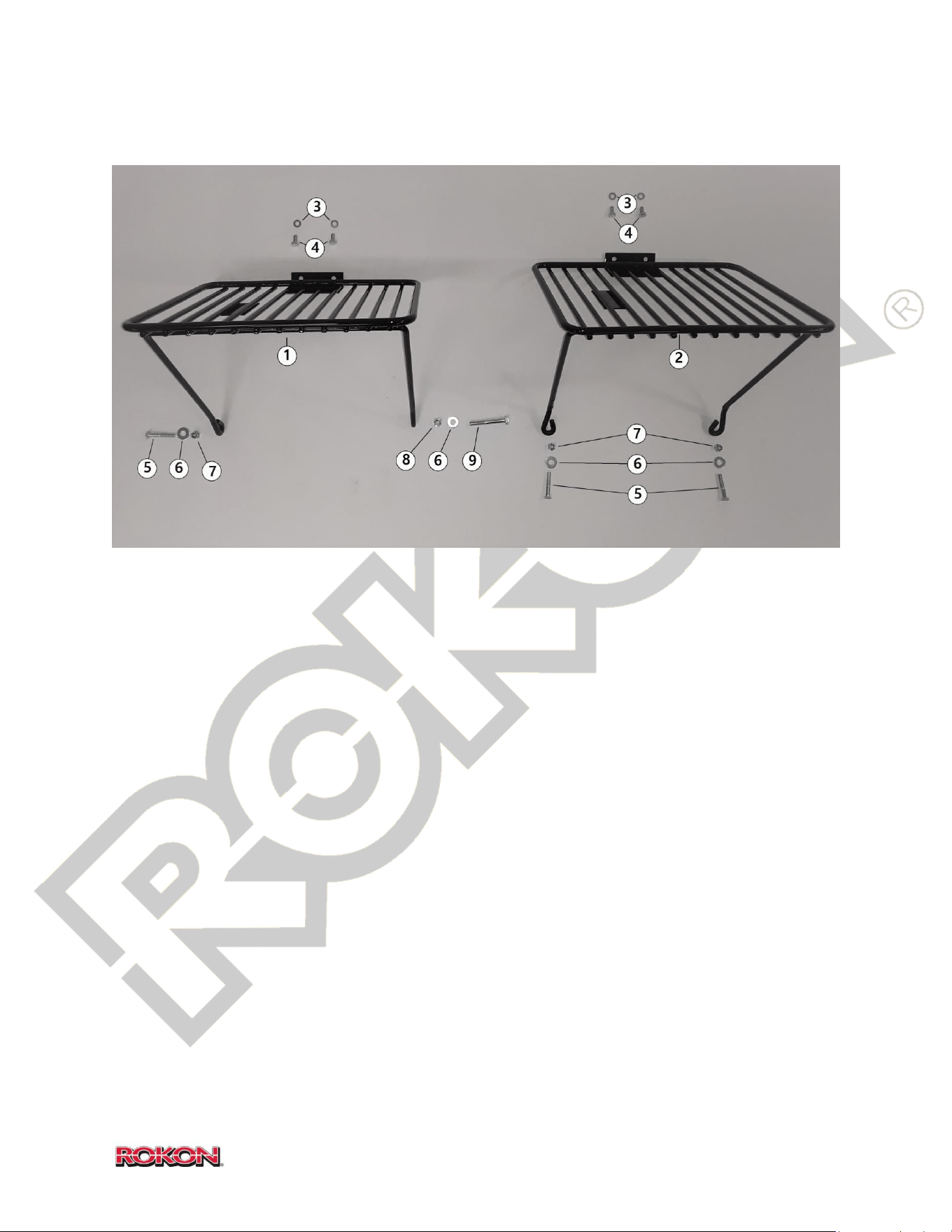
79
©2019 Rokon International Inc. Printed in U.S.A. ROKON® and its logo are registered trademarks
17-9 FRONT CARGO RACK
ITEM PART NUMBER DESCRIPTION QTY
1 110015 Front Cargo Rack (Trail-Breaker & Ranger) 0-1
2 100423 Front Cargo Rack (Scout) 0-1
3 100281 Washer, ¼ Lock 2
4 100167 Bolt, ¼-28 x ½ 2
5 100170 Bolt, ¼-28 x 1 ½ 1 - 2
6 100255 Washer, Flat 2
7 100169 Lock Nut, ¼-28 2
8 100171 Lock Nut, 5/16 - 18 (Autograb ONLY) 1
9 101529 Bolt, 5/16 - 18 (Autograb ONLY) 1
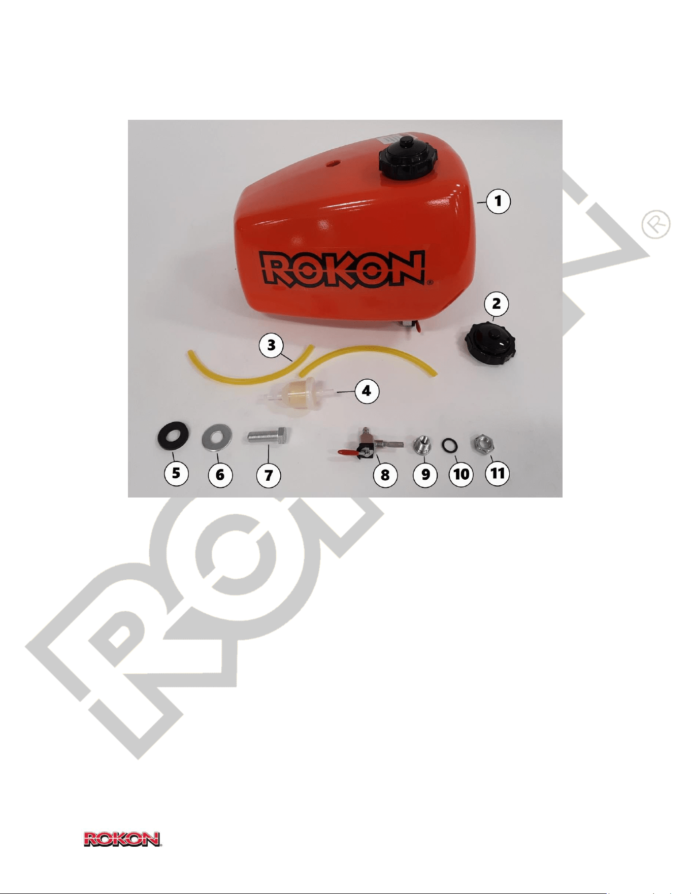
80
©2019 Rokon International Inc. Printed in U.S.A. ROKON® and its logo are registered trademarks
17-10 FUEL TANK
ITEM PART NUMBER DESCRIPTION QTY
1 103139 Fuel Tank Assembly, Steel 1
2 102847 Fuel Cap, Steel Tank 1
3 100122 Fuel Line Set (set of 2) 1
4 102766 Fuel Filter 1
5 101969 Rubber Fuel Tank Washer 1
6 102589 Flat Washer 1
7 101971 Bolt, ½-20 x 1 ½ 1
8 101295 Fuel Tank Shut-Off Valve 1
9 102590 Fuel Tank Fitting 1
10 102594 O-Ring Fuel Tank 1
11 102593 Nut, 9/16-18
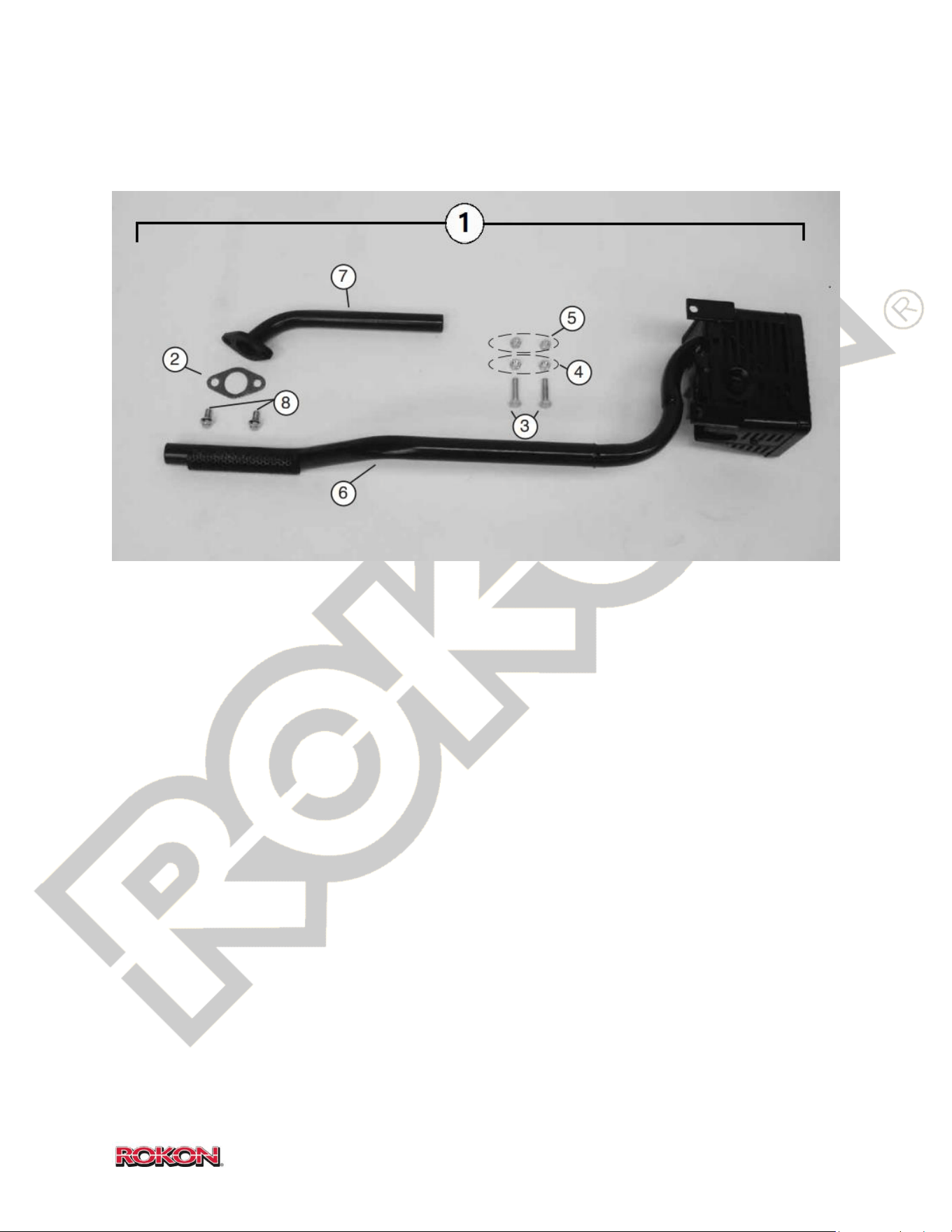
81
©2019 Rokon International Inc. Printed in U.S.A. ROKON® and its logo are registered trademarks
17-11 EXHAUST SYSTEM
ITEM PART NUMBER DESCRIPTION QTY
1 108237 Exhaust Assembly 7HP (Complete) 1
2 KOH1704109-S Gasket, Muffler 7HP 1
3 108123 Bolt, 5/16-24 x 1 ¼ 2
4 100211 Nut, 5/16 – 24 2
5 100551 Lock Nut, 5/16 – 24 2
6 108239A Exhaust, Muffler section 1
7 108239B Exhaust, Head Pipe 1
8 KOH25086224-S Head Pipe Bolt 2
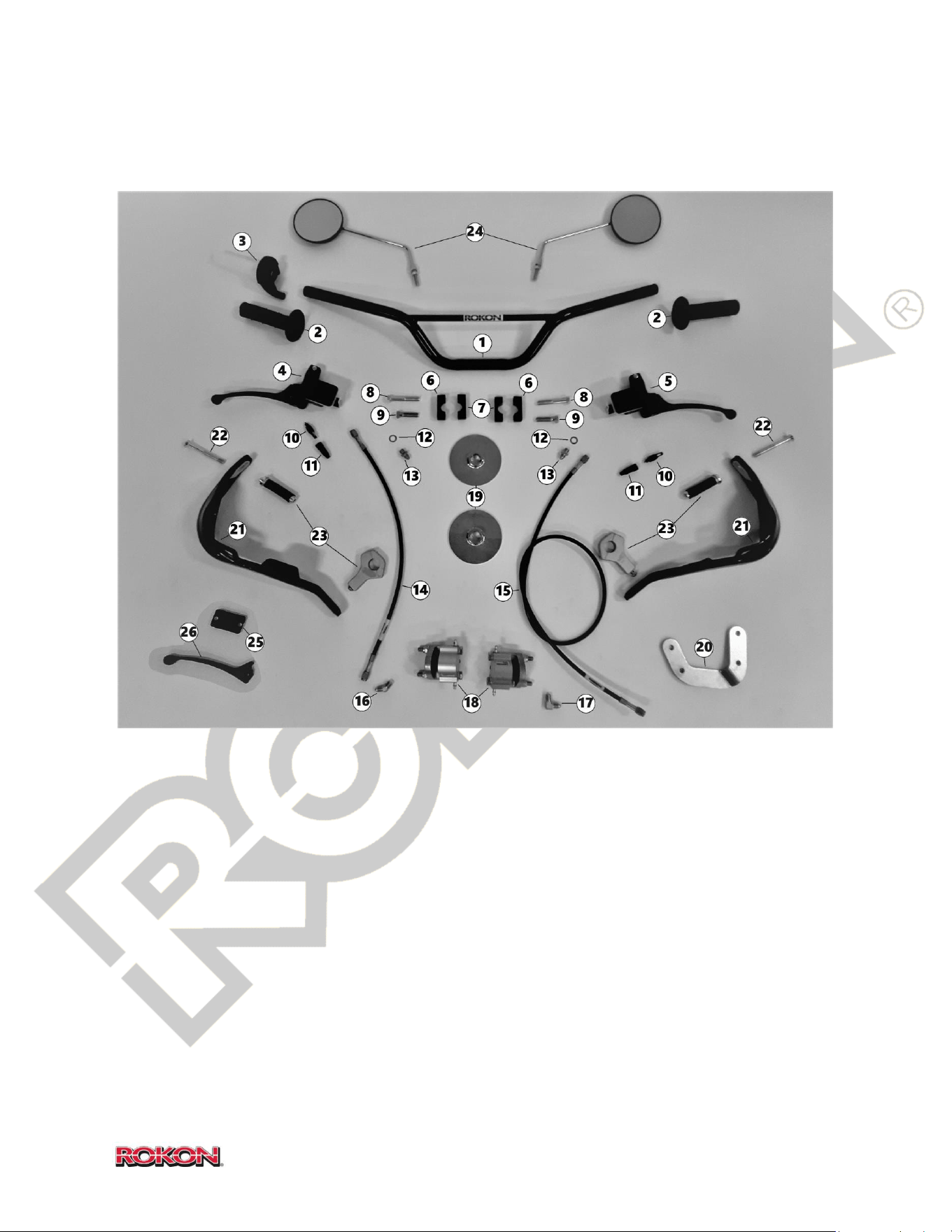
82
©2019 Rokon International Inc. Printed in U.S.A. ROKON® and its logo are registered trademarks
17-12 HANDLEBARS AND BRAKES
ITEM PART NUMBER DESCRIPTION QTY
1 100466 Handlebar 1
2 100071 Grip Set (Includes both grips) 1
3 103113 Throttle Twist Grip 1
4 108958 Front Brake Master Cylinder (Right) 1
5 108957 Rear Brake Master Cylinder (Left) 1
6 108115 Handle Bar Clamp, Upper 2
7 108116 Handle Bar Clamp, Lower 2
8 108986 Bolt, 3/8 – 24 x 2 ¼ 2
*Continued

83
©2019 Rokon International Inc. Printed in U.S.A. ROKON® and its logo are registered trademarks
17-12 (Continued)
ITEM PART NUMBER DESCRIPTION QTY
9 108985 Bolt, 3/8 – 24 x 1 ½ 2
10 104309 Brake Light Switch 2
11 107033 Brake Light Switch Dust Boot 2
12 GR44516 Master Cylinder Sealing Washer (copper) 2
13 GR306-03-31SZ1 Brake Hose Adapter Fitting (straight) 2
14 108960 Front Brake Hose 1
15 108961 Rear Brake Hose 1
16 GR823-03102 Brake Hose Adapter Fitting (45deg) 1
17 GR822-03DE Brake Hose Adapter Fitting (90deg) 1
18 108013 Brake Caliper Hydraulic 2
19 100610 Brake Disc 2
20 110032 Rear Brake Caliper Bracket 7HP 1
21 109019 Brush Busters (Complete, Optional) 1
22 108997 Brush Buster end bolt
23 109019H Brush Buster Hardware Kit
24 MIRROR Mirror, Set of 2 (Optional) 1
25 0413380 Brake Reservoir Diaphragm (Universal L/R) 2
26 100823 Brake Lever (Universal L/R) 2
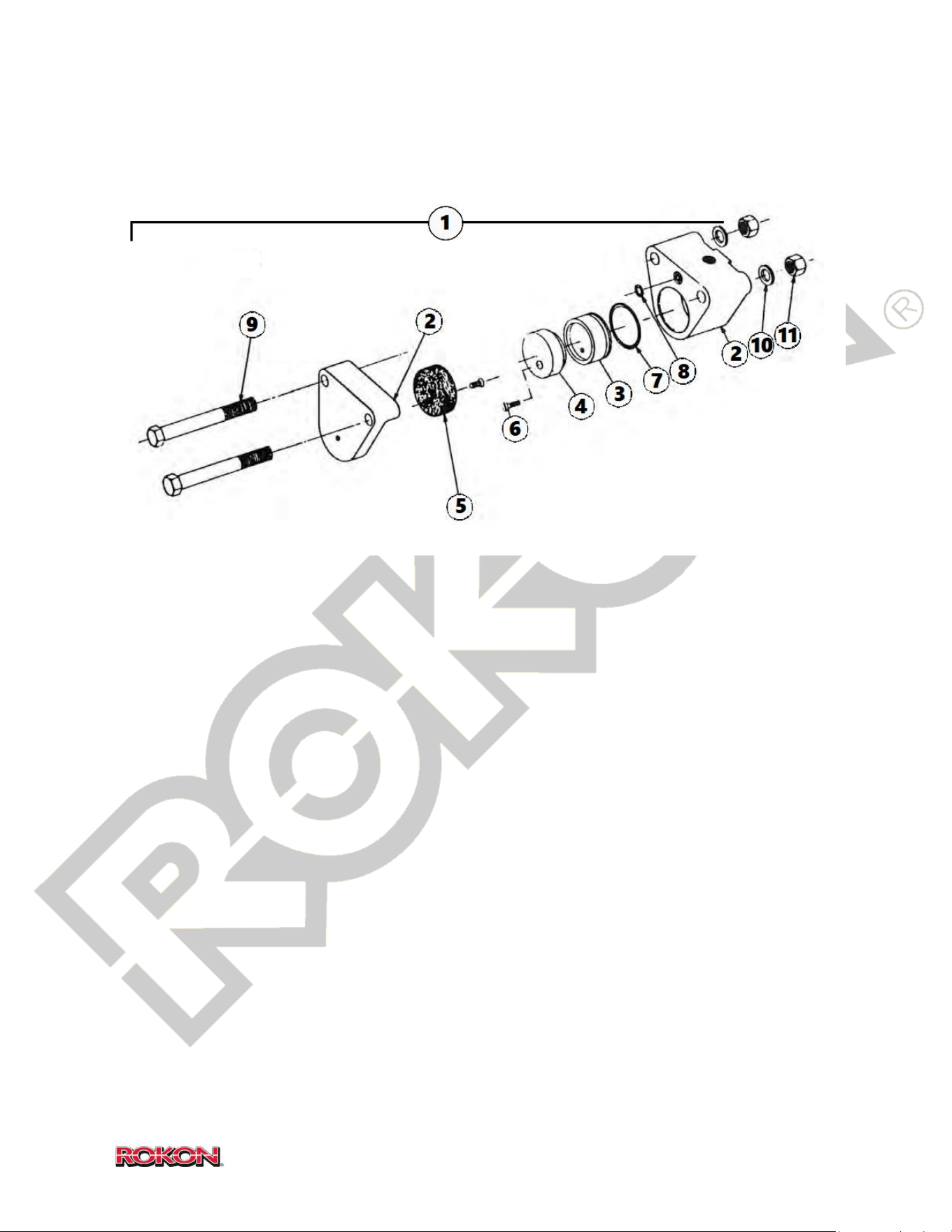
84
©2019 Rokon International Inc. Printed in U.S.A. ROKON® and its logo are registered trademarks
17-13 BRAKE CALIPER
ITEM PART NUMBER DESCRIPTION QTY
1 108013 Brake Caliper Assembly 2
2 0708-1001 Caliper Housing 2
3 0701-1062 Piston 2
4 108033 Brake Puck Live Side 2
5 108030 Brake Puck Dead Side 2
6 0701-1006 Screw, Brake Puck Retainer 2
7 0701-1004 O-Ring, Piston 2
8 0701-1003 O-Ring, Buna-N 2
9 3030-1007 Housing Bolt 4
10 0701-1007 Washer 4
11 0701-1008 Lock Nut 4
12 100481 Brake Puck Set (Includes 4 and 5)
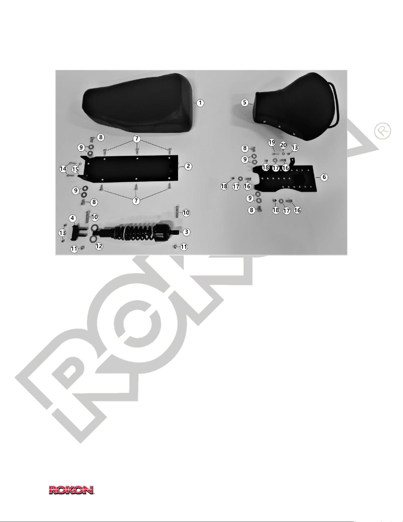
85
©2019 Rokon International Inc. Printed in U.S.A. ROKON® and its logo are registered trademarks
17-14 OPERATOR SEAT
ITEM PART NUMBER DESCRIPTION QTY
1 100452 Front Seat, Saddle Style 1
2 108063 Seat Base Plate 1
3 109002-S2 Seat Shock Absorber 1
4 108062 Lower Shock Mount 1
5 100136 Front Seat, Retro (optional) 1
6 110067 Retro Seat Base Plate (optional) 1
7 101629S Lag Bolt 6
8 100572 3/8 – 24 x 5/8 2
9 100208 Washer, ½ Flat 4
10 101181 Bolt, 3/8 – 24 x 1 ¾ 2
11 100212 Lock Nut, 3/8 – 24 2
12 300090C Washer, Flat 2
13 100169 Lock Nut, ¼ - 28 1-2
14 100277 Bolt, ¼ - 20 x 1 2
15 100281 Lock Washer, ¼ 2
16 100848 Bolt, 5/16 – 24 3
17 100202 Washer, 3/8 Flat 3
18 100551 Lock Nut, 5/16 – 24 3
19 100166 Bolt, ¼ - 28 x 1 1
20 100255 Washer, Flat 1-4
NS 100452-Camo Front Seat, Camouflage (Optional)
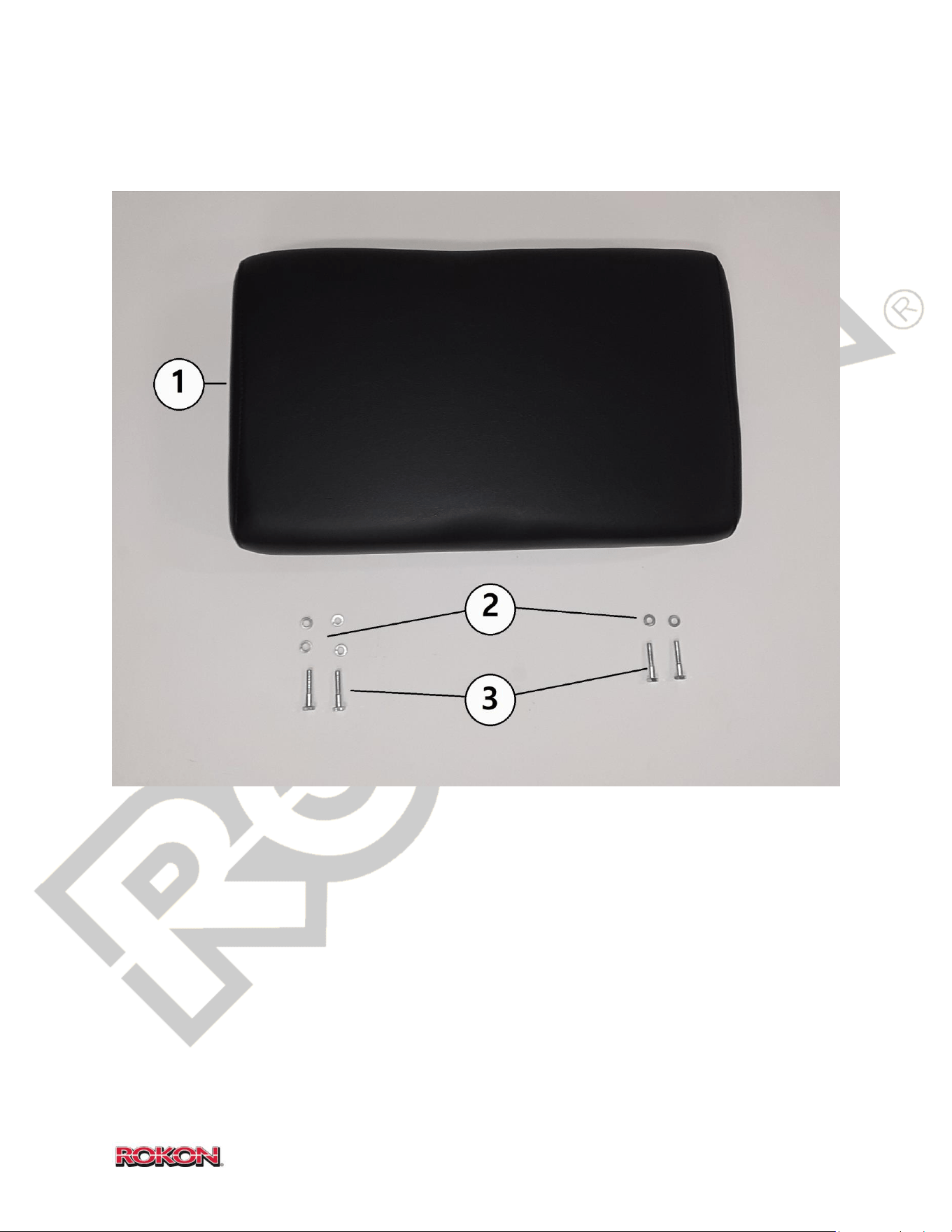
86
©2019 Rokon International Inc. Printed in U.S.A. ROKON® and its logo are registered trademarks
17-15 PASSENGER SEAT
ITEM PART NUMBER DESCRIPTION QTY
1 100340 Rear Seat 1
2 100281 Lock Washer, 1/4 6
3 105037 Bolt, ¼ - 20 x 1 3/8 4
NS 100340-C Rear Seat, Camouflage (Optional)
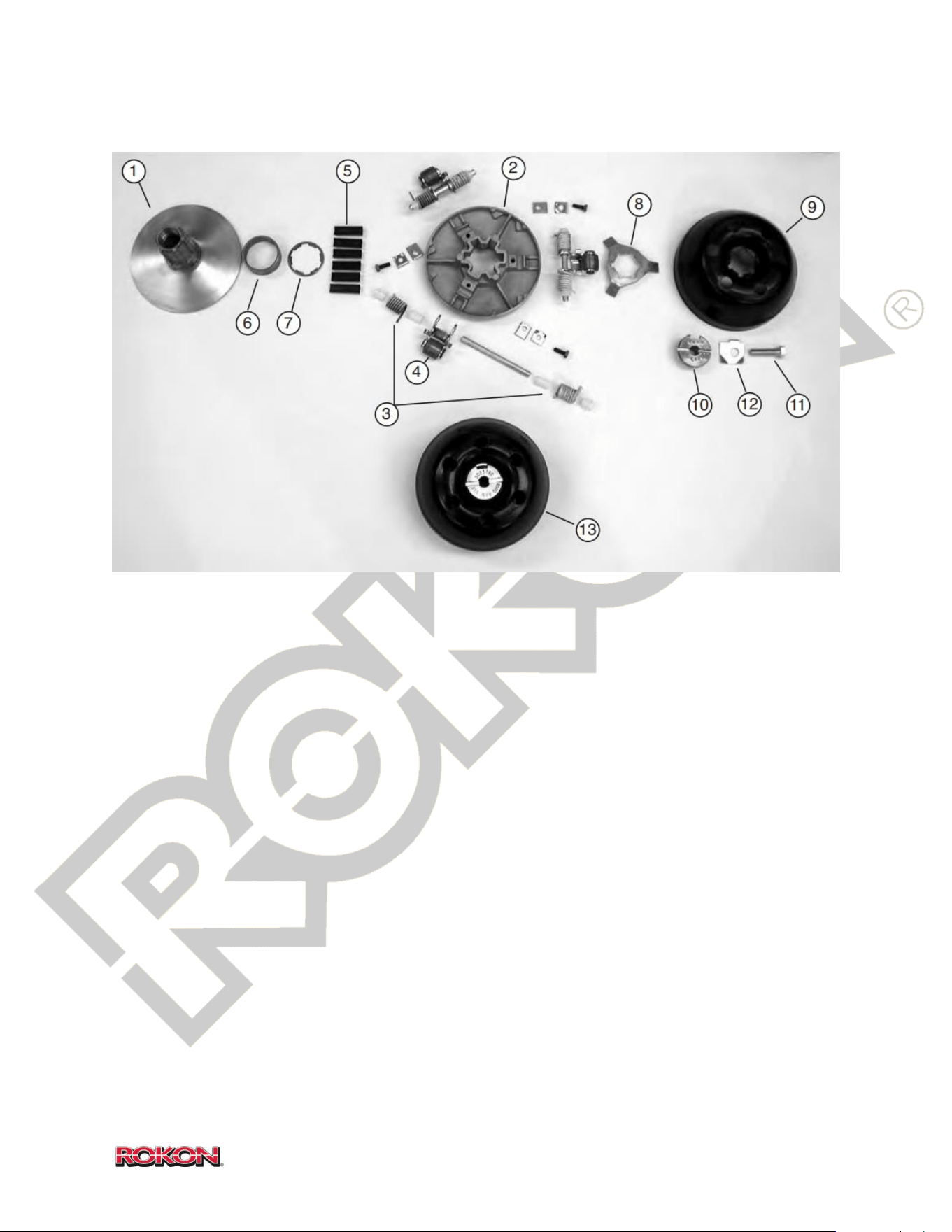
87
©2019 Rokon International Inc. Printed in U.S.A. ROKON® and its logo are registered trademarks
17-16 CVT DRIVE PULLEY (CLUTCH)
ITEM PART NUMBER DESCRIPTION QTY
1 703209 Fixed Face, Drive Pulley 1
2 601319 Movable Face, Drive Pulley 1
3 690144K Pivot Pin Kit (Includes Pins and Bushings) 1
4 690146K Roller Kit (Includes Rollers and Arms) 1
5 703128 Liner Spline 6
6 703116 Bearing, Idler 1
7 703127 Spline Washer 1
8 703129 Retractor Plate 1
9 703151 Ramp Plate 1
10 703211 Ramp Plate Retaining Bolt 1
11 108123 Clutch Mounting Bolt 1
12 108983 Locking Clip 1
13 100885 CVT Drive Pulley (Complete) 1
NS HOF302221A Spring Kit (Includes all 6 springs) 1
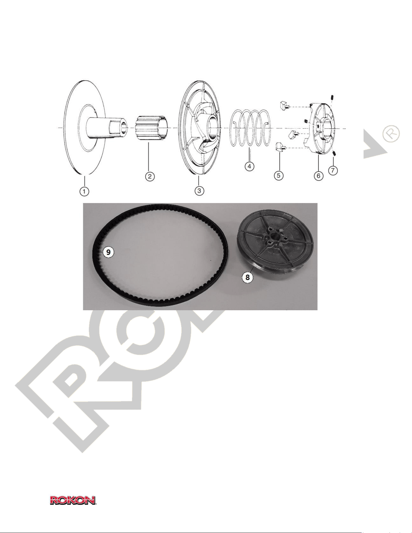
88
©2019 Rokon International Inc. Printed in U.S.A. ROKON® and its logo are registered trademarks
17-17 CVT DRIVEN PULLEY
ITEM PART NUMBER DESCRIPTION QTY
1 601311 Hub, Fixed Face, Driven Pulley 1
2 703110 Bearing 1
3 703109 Movable Face, Driven Pulley 1
4 703111 Spring 1
5 703305 Button Shoe Ramp 3
6 601406 Torque Bracket 1
7 901709 Set Screw, ¼ - 20 x 3/8 3
8 100884 CVT Driven Pulley (Complete) 1
9 108137 CVT Drive Belt 1
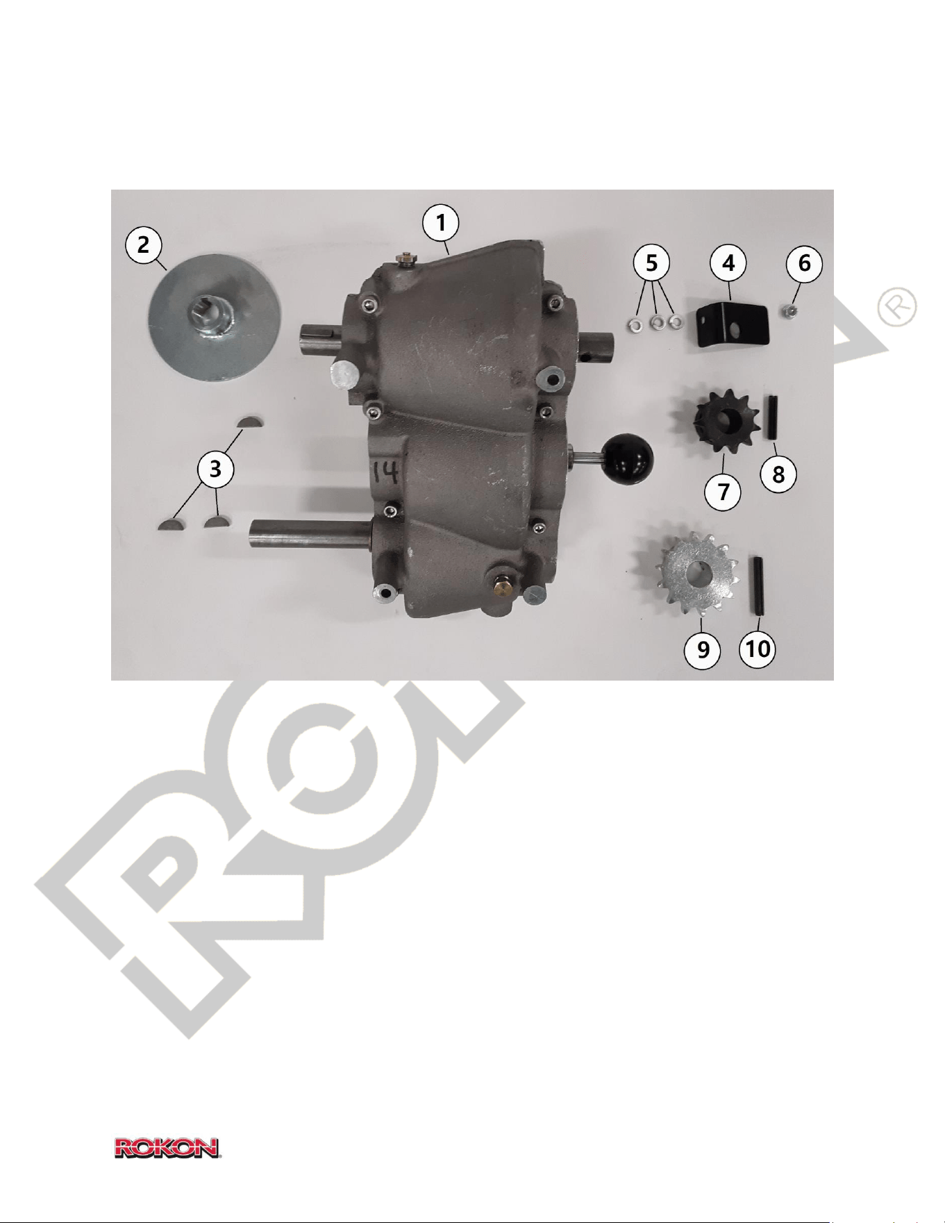
89
©2019 Rokon International Inc. Printed in U.S.A. ROKON® and its logo are registered trademarks
17-18 TRANSMISSION EXTERNAL
ITEM PART NUMBER DESCRIPTION QTY
1 103140 Transmission Assembly 1
2 100610 Brake Disc 1
3 100043 Woodruff Key, #9 3
4 108927 RHS Top Fairing Mounting Tab 1
5 100281 Lock Washer, ¼ 3
6 108997 Lock Nut, ¼ - 20 1
7 100040 Sprocket, 11 tooth 1
8 100270 Roll Pin, ¼ x 1 3/8 1
9 108257 Sprocket, 14 tooth (Ranger Only) 1
10 100272 Roll Pin, ¼ x 1 ¾ (Ranger Only) 1
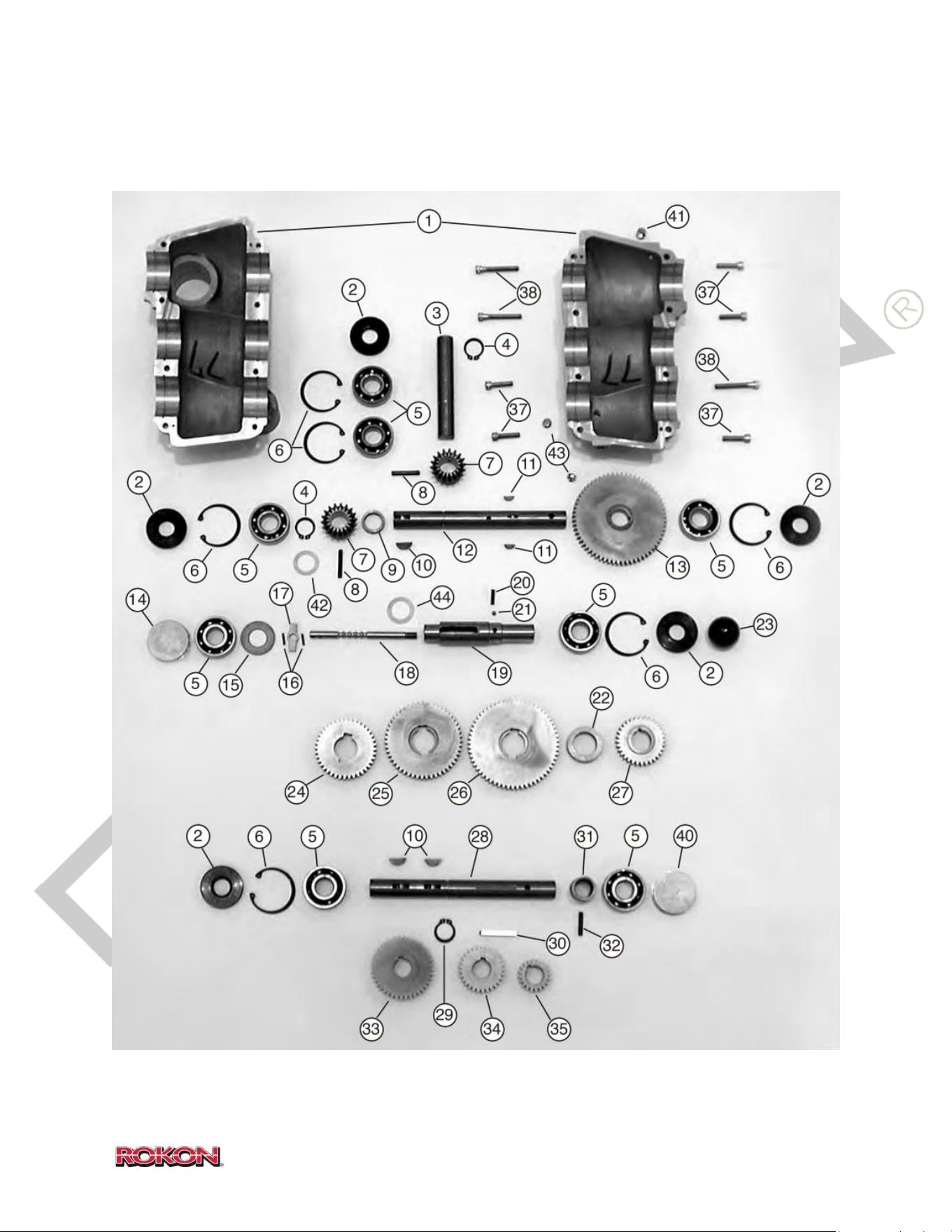
90
©2019 Rokon International Inc. Printed in U.S.A. ROKON® and its logo are registered trademarks
17-19 TRANSMISSION INTERNAL
*Continued

91
©2019 Rokon International Inc. Printed in U.S.A. ROKON® and its logo are registered trademarks
17-19 (Continued)
ITEM PART NUMBER DESCRIPTION QTY
1 103141 Transmission Casting Machined (2 halves) 1
2 101523 Oil Seal 5
3 103142 Shaft Front Output 1
4 103134 Snap Ring 2
5 100158 Bearing 8
6 103136 Snap Ring 6
7 100160 Miter Gear 2
8 100045 Roll Pin, 3/16 x 1 1/4 2
9 101519 Spacer 1
10 100043 Woodruff Key #9 3
11 101506 Key #3 3
12 103143 Shaft Rear Output 1
13 101517 Gear 64T Drive 1
14 105082-2 End Cap 1
15 101511 Spacer 1
16 101637 Roll Pin, 3/32 x 1/2 2
17 101633 Gear Selector 1
18 101634 Shift Rod 1
19 101632 Selector Shaft 1
20 101528 Spring 1
21 101527 Ball 1
22 101530 Spacer 1
23 101541 Shift Knob 1
24 101631-3 Gear 40T 1
25 101631-2 Gear 51T 1
*Continued

92
©2019 Rokon International Inc. Printed in U.S.A. ROKON® and its logo are registered trademarks
17-19 (Continued)
ITEM PART NUMBER DESCRIPTION QTY
26 101631-1 Gear 60T 1
27 101516 Gear 32T 1
28 107039 Shaft Input 1
29 101505 Snap Ring 1
30 101548 Key Straight Cut 1
31 101510 Spacer 1
32 100047 Roll Pin, 3/16 x 1 1
33 101509-3 Gear 40T 1
34 101509-2 Gear 29T 1
35 101509-1 Gear 20T 1
36 100163 Plug 2
37 101525 Bolt, ¼ - 20 X 1 1
38 101524 Bolt, ¼ - 20 X 1 3/4 1
39 101939 Dowel Pin 2
40 105082-1 End Cap 1
41 108987 Pressure Relief Valve 1
42 101615 Shim .005 AS NEEDED
43 100163 Plug, Drain/Check/Fill 2
44 101598 Shim (1x1.5) .010 1
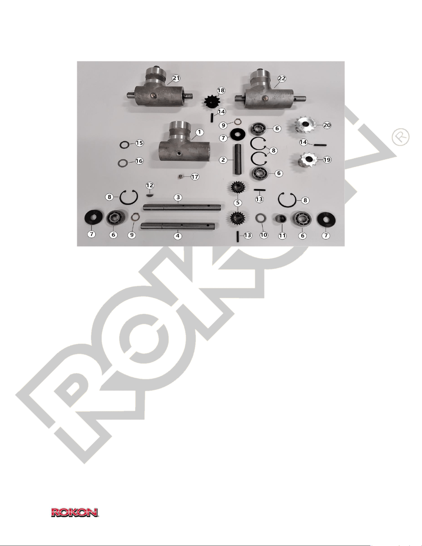
93
©2019 Rokon International Inc. Printed in U.S.A. ROKON® and its logo are registered trademarks
17-20 MITER BOX
ITEM PART NUMBER DESCRIPTION QTY
1 103130 Miter Box Case 1
2 108053 Input Shaft 1
3 110071 Output Shaft (Trail-Breaker & Ranger) 0-1
4 103132 Output Shaft (Scout) 0-1
5 100160 Miter Gear 2
6 100158 Bearing 4
7 101523 Oil Seal 3
8 103136 Snap Ring, Case ID 4
9 101505 Snap Ring, Shaft OD 2
10 100853 Spacer 1
11 100108 Spacer 1
12 100043 Woodruff Key #9 1
13 100045 Roll Pin, 3/16 x 1 ¼ 2
14 100270 Roll Pin, ¼ x 1 3/8 1
15 101615 Shim, ¾ ID x .005 AS NEEDED
16 101616 Shim, ¾ ID x .010 AS NEEDED
17 108987 Pressure Vent/Fill Plug 1
18 100040 Sprocket, 11T (Scout) 0-1
19 108331 Sprocket, 11T Extended (Trail-Breaker) 0-1
20 110050 Sprocket, 14T Extended (Ranger) 0-1
21 103131 Miter Box Assembly (Standard Fork) 0-1
22 103135 Miter Box Assembly (Autograb) 0-1
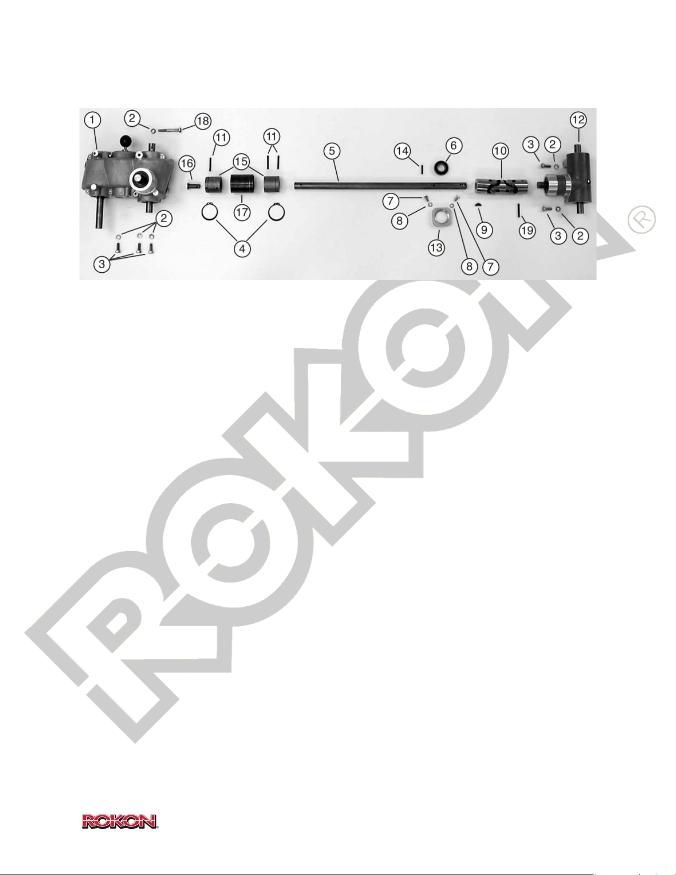
94
©2019 Rokon International Inc. Printed in U.S.A. ROKON® and its logo are registered trademarks
17-21 DRIVELINE
ITEM PART NUMBER DESCRIPTION QTY
1 103140 Transmission Assembly 1
2 100039 Lock Washer, 5/16 6
3 100038 Bolt, 5/16 – 18 x 7/8 5
4 100307 Snap Ring 2
5 108079 Drive Shaft 1
6 100314 Drive Line Bearing 1
7 100167 Bolt, 1/4-28 x 1/2 2
8 100281 Lock Washer, 1/4 2
9 100043 Woodruff Key #9 1
10 108054 Universal Joint 1
11 100046 Roll Pin, 3/16 x 1 1/2 3
12 103131 Miter Box Assembly (Scout Model Shown) 1
13 100312 Bearing Retainer Drive Line Support 1
14 100047 Roll Pin, 3/16 x 1 1
15 101655 Drive Line Boss 2
16 101656 Retaining Pin 1
17 100002 Overrunning Clutch Spring 1
18 101529 Bolt, 5/16-18 x 2 1/4 1
19 100045 Roll Pin, 3/16 x 1 1/4 1
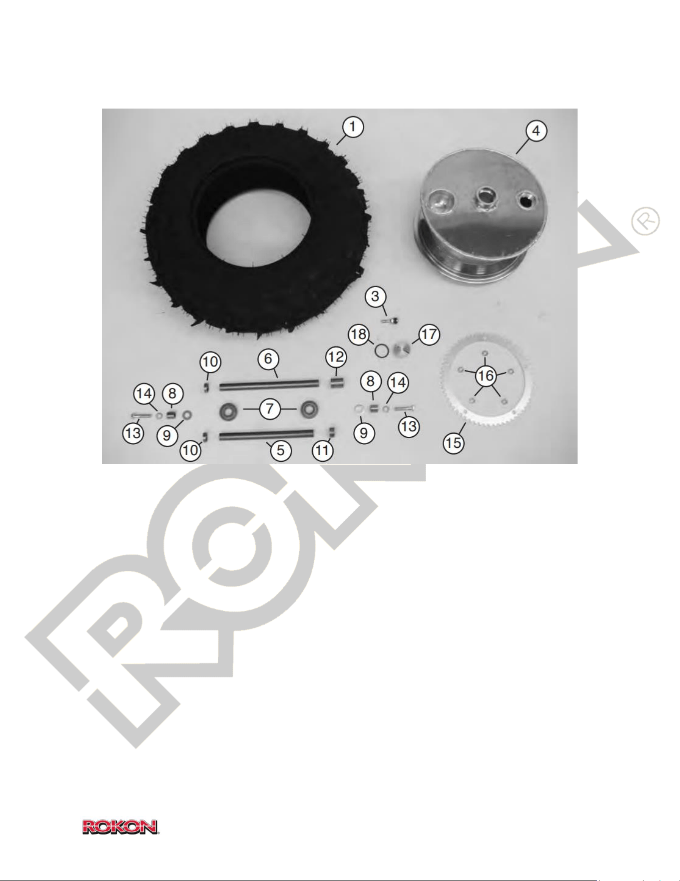
95
©2019 Rokon International Inc. Printed in U.S.A. ROKON® and its logo are registered trademarks
17-22 WHEEL (ALUMINUM DRUM)
ITEM PART NUMBER DESCRIPTION QTY
1 100840 Tire, 8 x 12 Maxxis 2.0 2
2 100846 Tire, Grim Reaper Radial (Not Shown) 2
3 100542 Valve Stem 12” Drum 2
4 108156A Aluminum Wheel 12” 2
5 100405 Axle, Scout front + All Rears 2-1
6 108329 Axle, Front Suspension (Trail-Breaker + Ranger) 1
7 100772 Bearing 4
8 100522 Axle Spacer 4
9 100208 Washer, Flat 4
10 100756 Spacer Dead Side 2
11 100758 Spacer Sprocket Side 2
12 108330 Spacer, Autograb Sprocket Side 1
13 101181 Bolt, 3/8-24 x 1 3/4 4
14 100288 Lock washer, 3/8 4
15 108112 Sprocket 60T 2
16 100036 Nut, 3/8 – 24 Jam 10
17 100523 Plug 2
18 100516 O Ring 2
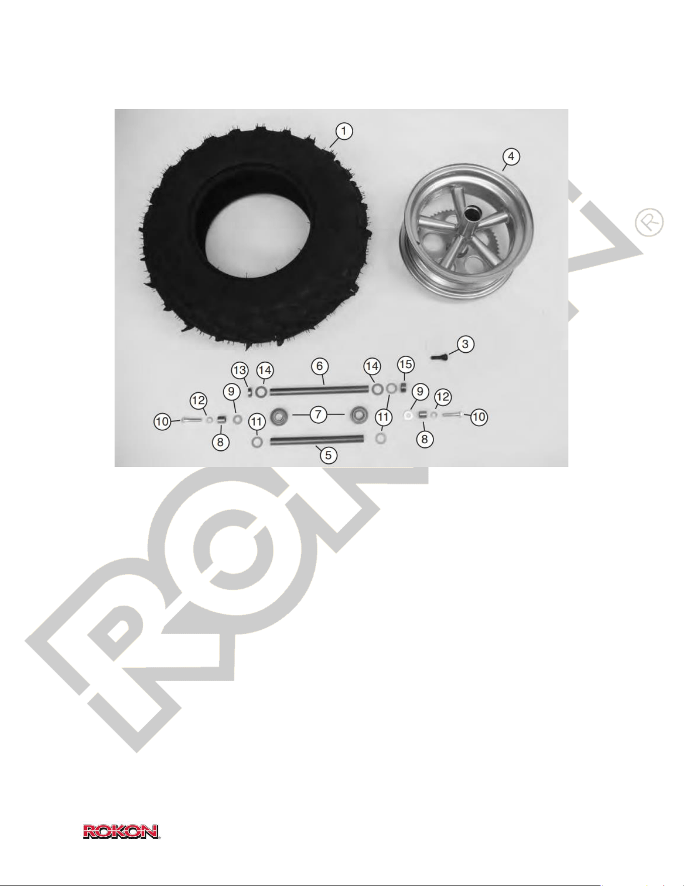
96
©2019 Rokon International Inc. Printed in U.S.A. ROKON® and its logo are registered trademarks
17-23 WHEEL (STEEL SPOKE)
ITEM PART NUMBER DESCRIPTION QTY
1 100836 Tire 8 x 12 Titan 489 XT 2
2 100846 Tire, Grim Reaper Radial (Not Shown) 2
3 100541 Valve Stem 12” Steel Wheel 2
4 100116 Wheel 12” Steel 2
5 100405 Axle, Scout front + All Rears 2-1
6 108329 Axle, Front Suspension (Trail-Breaker + Ranger) 1
7 100772 Bearing 2
8 100522 Axle Spacer 2
9 100208 Washer, Flat 2
10 101181 Bolt, 3/8-24 x 1 3/4 2
11 100853 Shim, ¾ 2
12 100288 Lock washer, 3/8 2
13 100756 Spacer, Dead Side 1
14 300090C Washer, ¾ 2
15 100758 Spacer, Sprocket Side 1
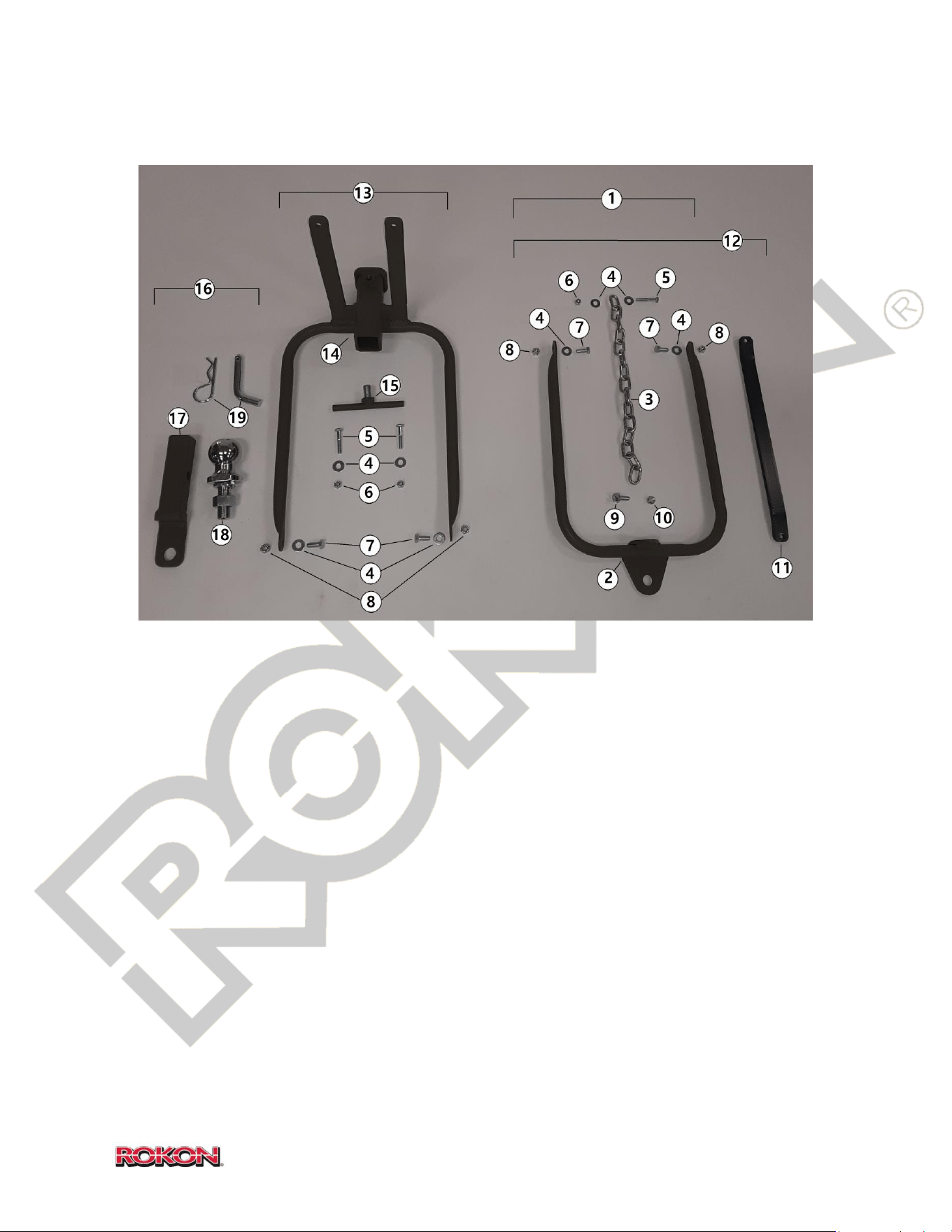
97
©2019 Rokon International Inc. Printed in U.S.A. ROKON® and its logo are registered trademarks
17-24 TOW BARS (OPTIONAL)
ITEM PART NUMBER DESCRIPTION QTY
1 100893 Tow Bar Kit Soft (Includes 2-10)
2 100349 Tow Bar 1
3 100007 Chain 1
4 100255 Washer, Flat 4
5 100170 Bolt, ¼ - 28 x 1 ½ 1-2
6 100169 Lock Nut, ¼ - 28 1-2
7 100848 Bolt, 5/16 – 24 x ¾ 2
8 100551 Lock Nut, 5/16 – 24 2
9 108943 Bolt, M8 x 1.25 -3/4 1
10 108966 Lock Nut, M8 x 1.25 1
11 103181 Rigid Tow Bar 1
12 100895 Tow Bar Kit Rigid (Includes 2-11)
13 100896 Receiver Tow Bar Kit (Includes 4,5,6,7,8,14,15)
14 100891 Receiver Tow Bar (1 ¼ Receiver Tube) 1
15 100890 Anti-Sway Tensioner Bolt 1
16 100897 Ball Insert Kit for 100896 (Includes 17,18,19)
17 105023 1 ¼ Ball Mount Insert 1
18 105029C Trailer Ball 1
19 105025 Pin + Clip, Insert Retainer 1
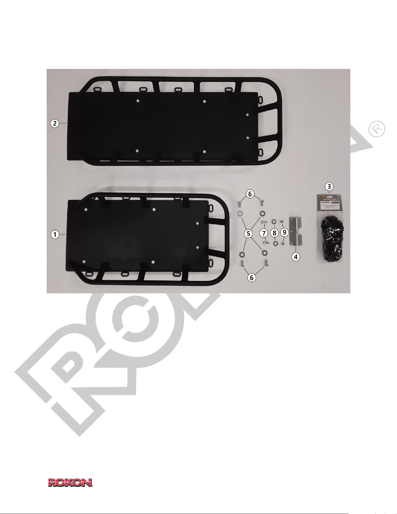
98
©2019 Rokon International Inc. Printed in U.S.A. ROKON® and its logo are registered trademarks
17-25 REAR CARGO RACK (OPTIONAL)
ITEM PART NUMBER DESCRIPTION QTY
1 109018 Rear Cargo Rack 1
2 109020 *Extended Rear Cargo Rack (Mototractor) 1
3 108948 Cargo Netting 1
4 101136 Tail Light Bracket, Cargo Rack 1
5 100208 Washer, Flat 4
6 101572 Bolt, 3/8 – 24 4
7 100848 Bolt, 5/16 – 24 x ¾ 2
8 100202 Washer, Flat 2
9 100551 Lock Nut, 5/16 – 24 2
*Extended Rear Cargo Rack can only be used in conjunction with the Retro Seat Assembly (See section 17-14)
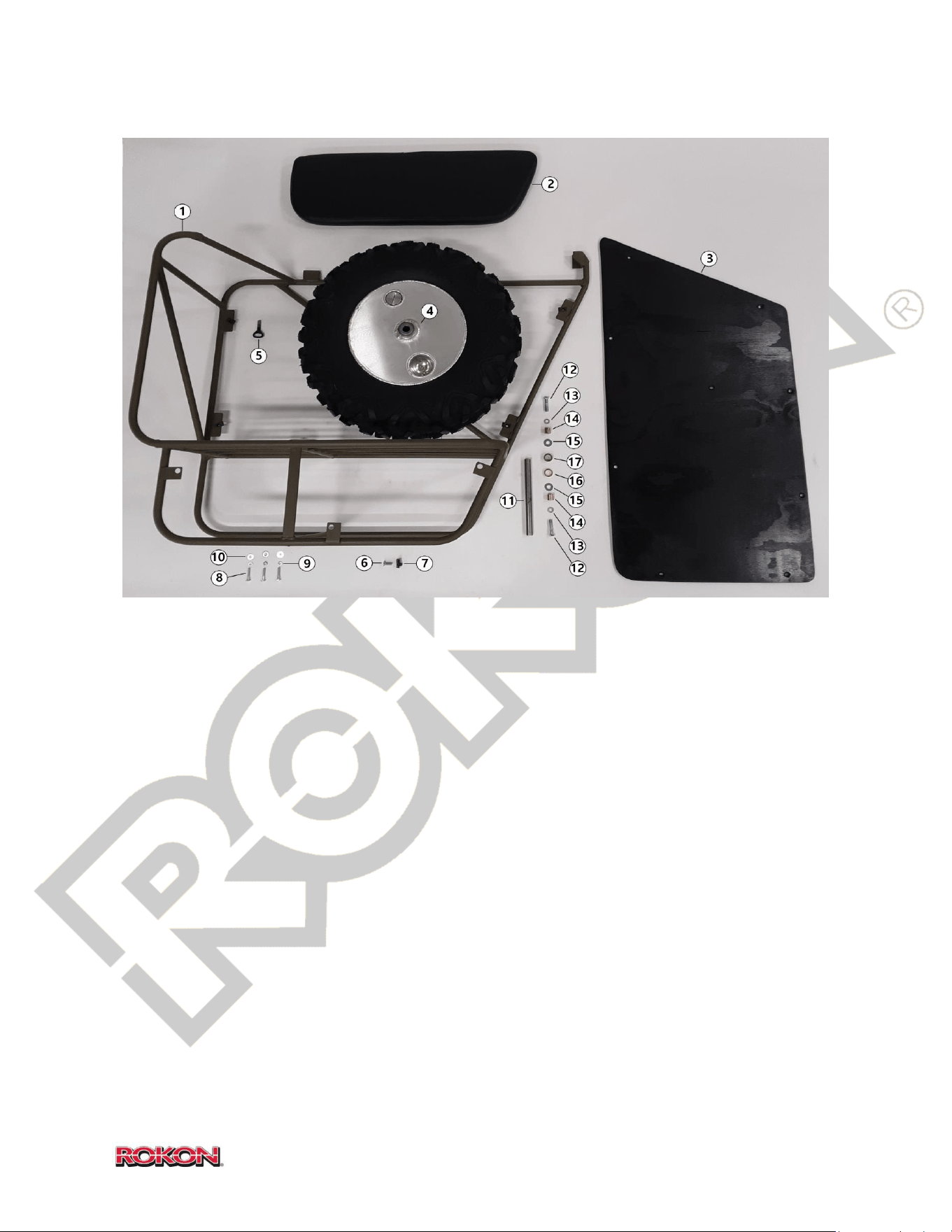
99
©2019 Rokon International Inc. Printed in U.S.A. ROKON® and its logo are registered trademarks
17-26 SIDECAR (OPTIONAL)
ITEM PART NUMBER DESCRIPTION QTY
1 108156F Sidecar Frame 1
2 100454 Sidecar Seat 1
3 108156D Decking, Sidecar 1
4 108157 *Drum Wheel, Sidecar (No Sprocket) 1
5 104167 Thumb Bolt, 3/8 – 24 x 1 ¾ 1
6 FHA05C016Z Deck Retaining Bolt, 9
7 101630 Receptacle Nut, Deck 9
8 105037 Bolt, ¼ - 20 x 1 3/8 3
9 100281 Lock Washer, 1/4 3
10 100255 Washer, Flat 3
11 100405 Axle 1
12 101181 Bolt, 3/8-24 x 1 3/4 2
13 100288 Lock washer, 3/8 2
14 100522 Axle Spacer 2
15 100208 Washer, Flat 2
16 100756 Spacer, Fill Side 2
17 100758 Spacer, Flat Side 2
ALL ABOVE 104166 Sidecar Assembly
NS 100454MB Sidecar Seat, Camouflage
NS 100116S *Spoke Wheel, Sidecar (No Sprocket) 1
*See sections 17-22 & 17-23 for wheel assembly details, sidecar wheel has no sprocket.
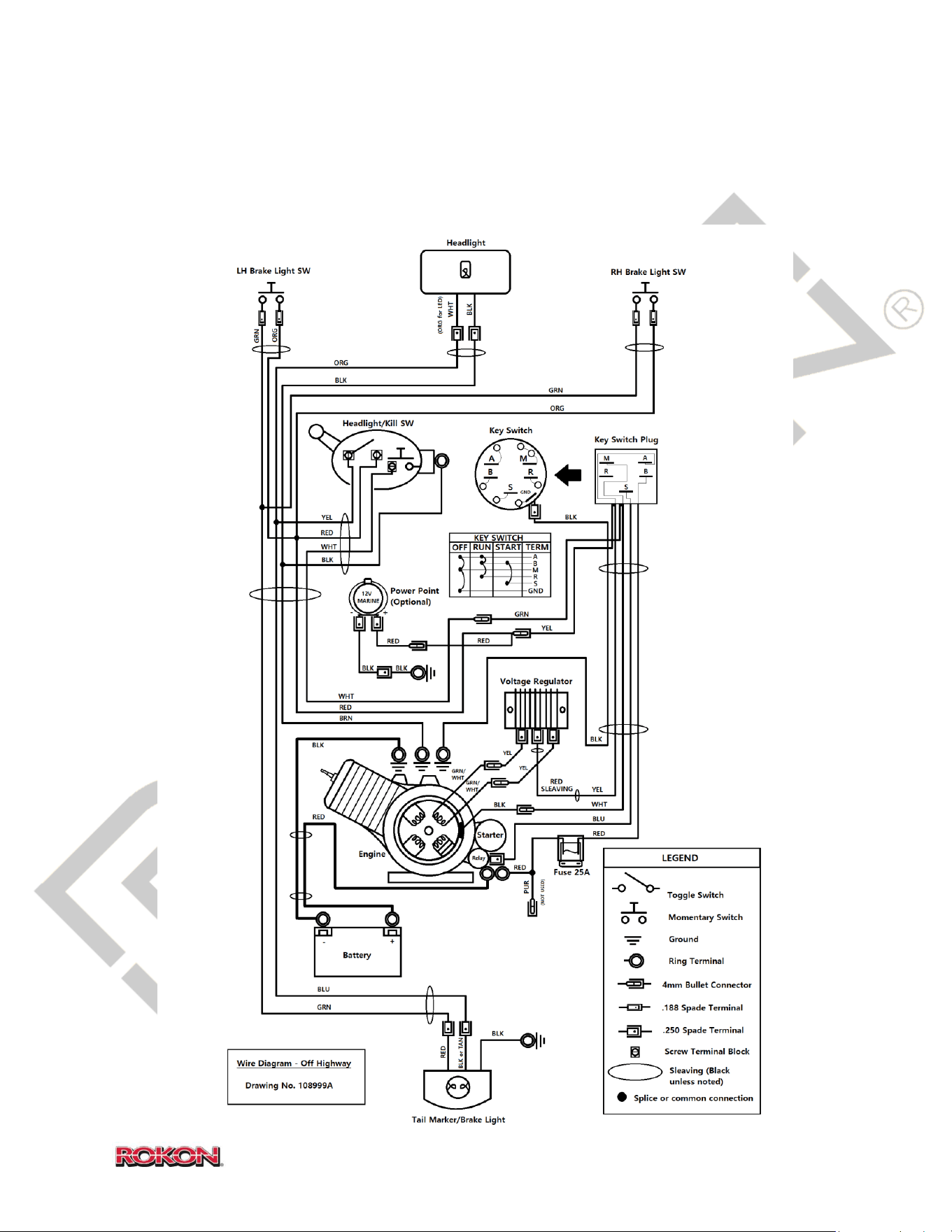
100
©2019 Rokon International Inc. Printed in U.S.A. ROKON® and its logo are registered trademarks
18. WIRING DIAGRAMS
Off – Highway, SCOUT and TRAIL-BREAKER
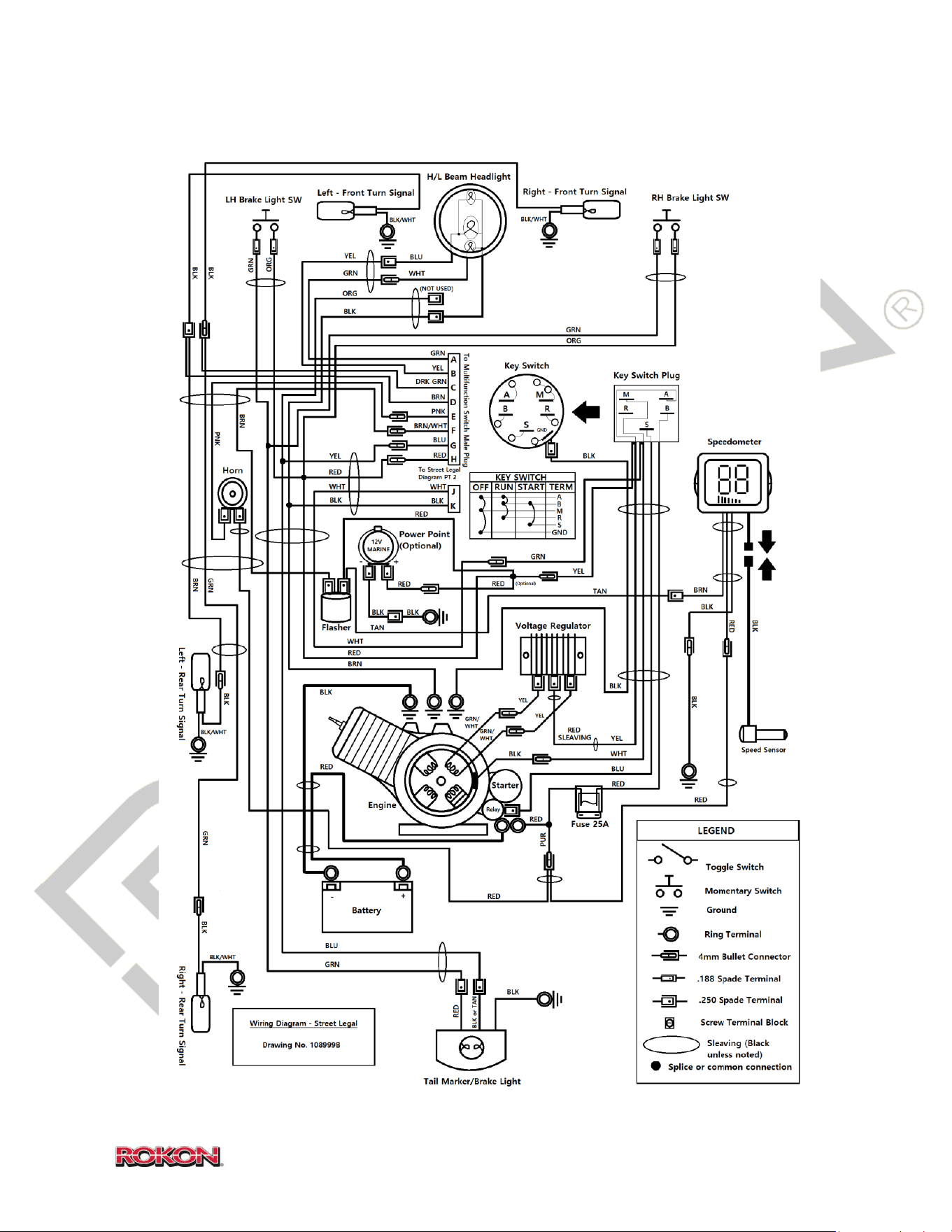
101
©2019 Rokon International Inc. Printed in U.S.A. ROKON® and its logo are registered trademarks
Street Legal RANGER PART 1
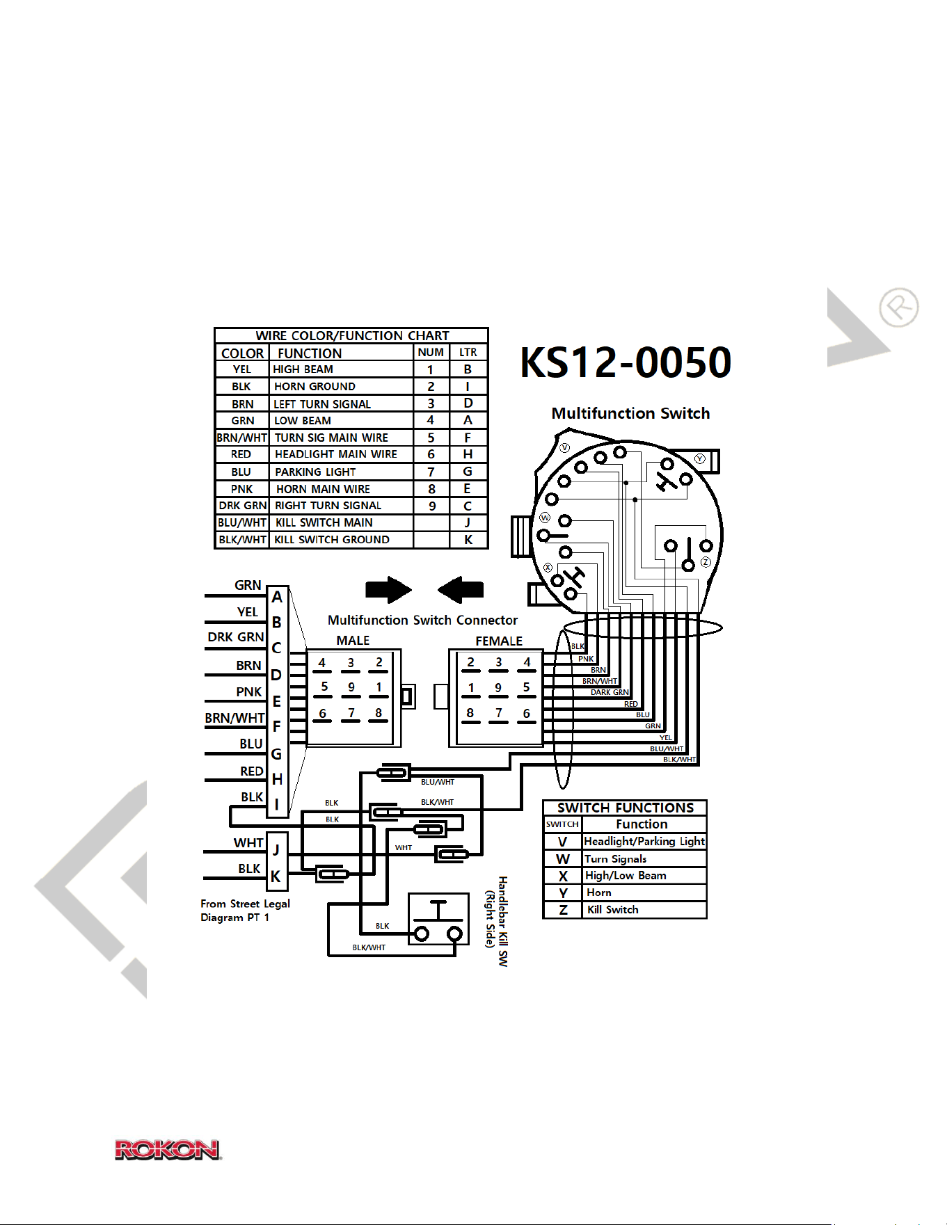
102
©2019 Rokon International Inc. Printed in U.S.A. ROKON® and its logo are registered trademarks
WIRING DIAGRAMS (Continued)
Street Legal RANGER PART 2
103
19. WARRANTY INFORMATION
ROKON WARRANTY SYSTEM
ROKON International Inc. warranties to the original purchaser, new ROKON Utility Vehicles
to be free of defects that are the result of faulty workmanship or material, for a period of
one year from the date of purchase for new year model ROKONs only. In the case of
competition machines, no warranty is expressed or implied. The entire risk to the quality
and performance of competition machines is with the buyer.
Warranty will be honored through any authorized ROKON dealer or the factory. To validate
warranty, Purchaser must: Complete and return Warranty Registration Card to ROKON
International Inc. within ten (10) days of purchase.
Notify ROKON of any and all defects made within ten (10) days of malfunction and make
machine immediately available for inspection at a place to be determined by ROKON.
Have warranty service performed by an authorized ROKON agent as directed by ROKON.
Warranty will not cover:
Parts replaced as a result of normal wear. (ie. spark plugs, tires, tubes, and so forth)
Parts subject to misuse, neglect, or modification.
Parts damaged as a result of accident or collision.
Machines used for rental and/or lease.
Machines used in competitive events.
Machine abuse.
ROKON International Inc.’s liability shall be limited to that set forth herein, and no other
claims for consequential damage or injury to person or property will be admissible. All other
conditions and warranties, statutory or otherwise, and whether expressed or implied,
including, but not limited to, implied warranties of merchantability or fitness for a particular
use, are hereby excluded. This implied warranty exclusion is not applicable in states having
laws to the contrary.
104
20. EMISSIONS CONTROL SYSTEM INFORMATION
Rokon International Inc. – Emission Control System Warranty Statement
YOUR WARRANTY RIGHTS AND OBLIGATIONS
The U.S. Environmental Protection Agency and Rokon International Inc. (hereinafter “Rokon”), are pleased to
explain the emission control system warranty on your Off-Road Motorcycle. New off-road motor vehicles
must be designed, built and equipped to meet U.S. EPA Federal and California anti-smog standards. Rokon
must warrant the emission control system on your vehicle for 5,000 km, or at least 30 months, whichever
comes first, provided that there has been no abuse, neglect or improper maintenance of your vehicle. This
off-road motorcycle was designed to meet the emission standards for 10,000 km, or five years, whichever
comes first.
Your emission control system may include parts such as the carburetor or fuel injection system, the ignition
system, catalytic converter and engine computer, if it is equipped. Also included may be hoses, belts,
connectors and other emission-related assemblies.
Where a warrantable condition exists, Rokon will repair your vehicle at no cost to you, including diagnosis,
parts and labor.
If an emission-related part on your vehicle is defective, the part will be repaired or replaced by Rokon. This is
your emission control system DEFECTS WARRANTY.
NOTICE! Use of any Rokon brand vehicle in any type of competitive event completely and absolutely voids
this and all other warranties offered by Rokon.
OWNER’S WARRANTY RESPONSIBILITIES
As the vehicle owner, you are responsible for the performance of the required maintenance listed in your
owner’s manual. Rokon recommends that you retain all receipts covering maintenance on your vehicle, but
Rokon cannot deny warranty solely for the lack of receipts or for your failure to ensure the performance of all
scheduled maintenance.
You are responsible for presenting your vehicle to the Rokon dealer as soon as a problem exists. The warranty
repairs should be completed in a reasonable amount of time, not to exceed 30 days.
As the vehicle owner, you should be aware that Rokon may deny your warranty coverage if your vehicle or a
part has failed due to abuse, neglect, improper maintenance or unapproved modifications.
If you use your vehicle in any type of competitive event, this warranty is immediately and completely void.
If you have any questions regarding your warranty rights and responsibilities, you should contact Rokon
International Inc., 50 Railroad Avenue, Rochester, NH 03839, Phone: 603-335-3200, or the U.S. Environmental
Protection Agency at 2000 Traverwood Drive, Ann Arbor, MI 48105.
105
Rokon International Inc. - Limited Warranty on Emission Control System
YOUR WARRANTY RIGHTS AND OBLIGATIONS
Rokon warrants that each new Rokon brand off-road motorcycle:
A. is designed, built and equipped so as to conform at the time of initial retail purchase with all applicable
regulations of the United States Environmental Protection Agency, and the California Air Resources Board;
and
B. is free from defects in material and workmanship which cause such vehicle to fail to conform to
applicable regulations of the United States Environmental Protection Agency or the California Air Resources
Board for the periods specified above.
I. Coverage. Warranty defects shall be remedied during customary business hours at any authorized
Rokon dealer located within the United States of America in compliance with the Clean Air Act and
applicable regulations of the United States Environmental Protection Agency and the California Air
Resources Board. Any part or parts replaced under this warranty shall become the property of
Rokon.
II. Limitations This Emission Control System Warranty shall not cover any of the following:
A. Repair or replacement as a result of
(1) accident,
(2) misuse,
(3) repairs improperly performed or replacements improperly installed,
(4) use of replacement parts or accessories not conforming to specifications set forth by Rokon,
which adversely affect performance and/or
(5) use in competitive racing or related events.
B. Inspections, replacement of parts and other services and adjustments required for required
maintenance.
C. Any vehicle equipped with an odometer or hour meter on which the odometer mileage or hour meter
reading has been changed so that actual mileage cannot be readily determined.
III. Limited Liability
A. The liability of Rokon under this Emission Control System Warranty is limited solely to the
remedying of defects in material or workmanship by an authorized Rokon dealer at its place of
business during customary business hours. This warranty does not cover inconvenience or loss of use
of the vehicle or transportation of the vehicle to or from the Rokon dealer. Rokon shall not be liable
for any other expenses, loss or damage, whether direct, indidental, consequential or exemplary
arising in connection with the sale or use of or inability to use the Rokon brand vehicle for any
purpose. Some states do not allow the exclusion or limitation of any incidental or consequential
damages, so the above limitations may not apply to you.
106
Rokon International Inc. - Limited Warranty on Emission Control System
B. No express emission control system warranty is given by Rokon, except as specifically set forth herein.
Any emission control system warranty implied by law, including any warranty of merchantability or fitness
for a particular purpose, is limited to the express emission control system warranty terms stated in this
warranty. The foregoing statements of warranty are exclusive and in lieu of all other remedies. Some
states do not allow limitations on how long an implied warranty lasts, so the avove limitations may not
apply to you.
C. No dealer is authorized to modify this Limited Emission Control System Warranty issued by Rokon.
IV. LEGAL RIGHTS. This warranty gives you specific legal rights, and you may also have other rights which
vary from state to state.
V. This warranty is in addition to the Rokon limited vehicle warranty.
VI. ADDITIONAL INFORMATION. Any replacement part that is equivalent in performance and durability may
be used in the performance of any maintenance or repairs. However, Rokon are not liable for these parts.
The owner is responsible for the performance of all required maintenance. Such maintenance may be
performed at a service establishment or by any individual. The warranty period begins on the date the OFMC
is delivered to an ultimate purchaser.
If you have any questions regarding your warranty rights and responsibilities, you should contact Rokon
International Inc., at the address and phone number listed below, or the U.S. Environmental Protection
Agency at 2000 Traverwood Drive, Ann Arbor, MI 48105.
Rokon International Inc.
50 Railroad Avenue
Rochester, NH 03839
Phone: 603-335-3200
Fax: 603-335-4400
Toll Free: 800-593-2369

21. MAINTENANCE RECORDS/NOTES
________________________________________________________________
________________________________________________________________
________________________________________________________________
________________________________________________________________
________________________________________________________________
________________________________________________________________
________________________________________________________________
________________________________________________________________
________________________________________________________________
________________________________________________________________
________________________________________________________________
________________________________________________________________
________________________________________________________________
________________________________________________________________
________________________________________________________________
________________________________________________________________
________________________________________________________________
________________________________________________________________
________________________________________________________________
________________________________________________________________
________________________________________________________________
________________________________________________________________

________________________________________________________________
________________________________________________________________
________________________________________________________________
________________________________________________________________
________________________________________________________________
________________________________________________________________
________________________________________________________________
________________________________________________________________
________________________________________________________________
________________________________________________________________
________________________________________________________________
________________________________________________________________
________________________________________________________________
________________________________________________________________
________________________________________________________________
________________________________________________________________
________________________________________________________________
________________________________________________________________
________________________________________________________________
________________________________________________________________
________________________________________________________________
________________________________________________________________
________________________________________________________________
____________________________________________________________