
KA3000 Series User Manual
Multiple Channel digital control and
programmable DC power supply
User Manual
SHENZHEN KORAD TECHNOLOGY CO., LTD.
Address:F3, Building A4, District B, Songbai Industrial Park,
Guangming New District, Shenzhen, 518106, P.R.China.
Tel: 86-755-61535026 Fax: 86-755-61535025
E-mail: adam@koradtechnology.com
www.koradtechnology.com
www.korad.com.cn
1
SAFETY SYMBOLS
This chapter contains important safety instructions that you
must follow when operating the KA3000- Series and when
keeping it in storage. Read the following before any operation
to insure your safety and to keep the best condition for the
KA3000- Series.
Safety Symbols
These safety symbols may appear in this manual or on the series.
WARNING
DANGER High Voltage。
Earth (ground) Terminal
!
KA3000-Series User Manual
Saf ety Gui del ines
•Avoid severe im pacts or rough handli ng th at leads to
damage.
•Do not disassemble unless you are quali fie d as
service personnel.
AC INPU T
•AC Inut Vol tage : 110V / 120 V / 220 V / 230 V , 50 / 60 Hz
•Conn ect the pr ot ec tive gr oun di ng co ndu ct or of the AC
power co rd to an ear th gr oun d, to avoid electrica l
shock.
FUSE
•To ens ur e fire protection, repl ace the fus e onl y with the sp ec ified typ e
and rat ing.
•Disc onn ec t the power co rd bef ore fuse repl ac em ent .
•Mak e su re the cause of fus e bl owout is fixe d bef or e fus e repl acement .
!
•Do not discharge sta tic ele ctr icity .
•Do not block or obstruct th e cooli ng fa n vent opening.
!
!
!
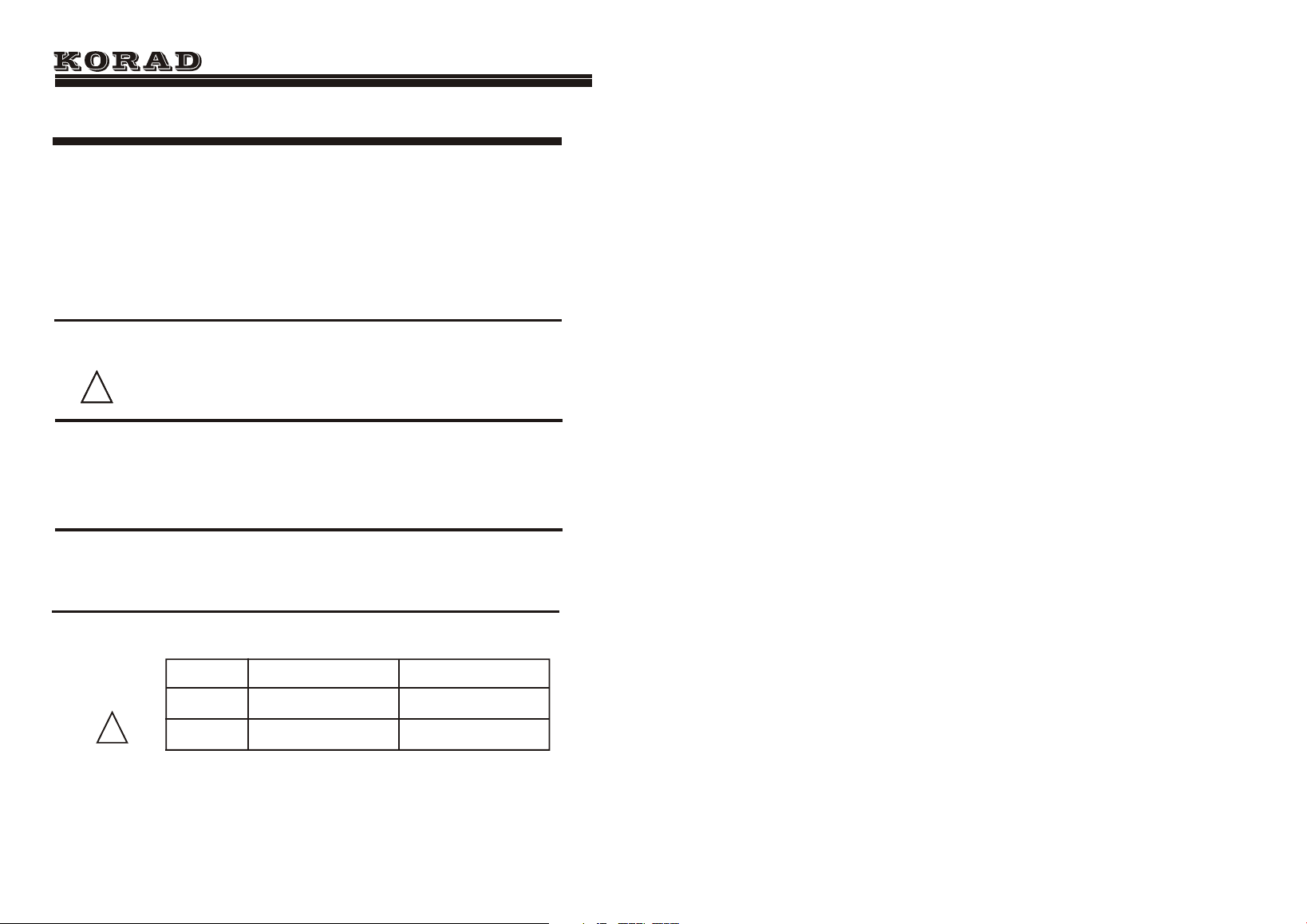
!
Mode l
KA330 3
KA330 5
110V/ 120 V
220 V/230 V
T8A /250 V(20X5m m)
T10A/250V( 20X5mm)
T4A /250 V(20x 5mm)
T5A /250 V(20x 5mm)
SAFETY INSTRUCTION
Operation
Environment
•Location: Indoor, no direct sunlight, dust free,
almost non-conductive pollution (note below)
•Relative Humidity: < 80%
•Altitude: < 2000m
•Temperature: 0-40℃
Storage
environment
•Location: Indoor
•Relative Humidity: < 70%
•Temperature: -10-70℃−
KA3000-Series User Manual
2
3
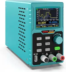
Main Features
● 4digit displays, and accurate outputs
● Parameters settings on Overcurrent
Protection and Overvoltage Protection
● 5 groups of memories for fast recall
● Shutdown memory function
● Software calibration
● Keyboard Lock
● Low-speed and stepless-speed fan
● Overtemperature Protection
Introduction
KA3000-Series User Manual
Voltage Rise
Reaction Time
≤100mS
≤100mS
≤100mS
≤100mS
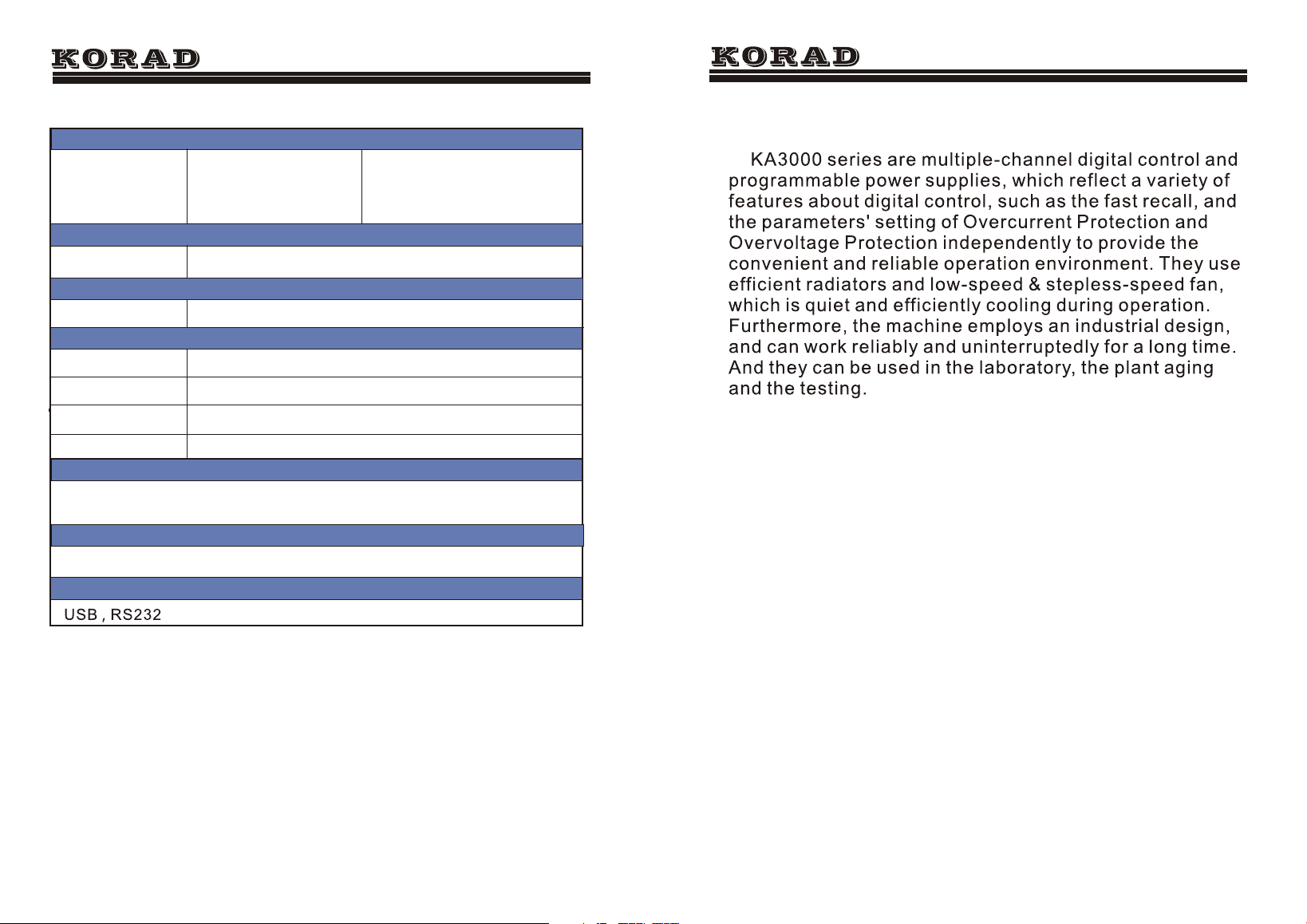
252(W)*135(H)*370(D), KA3303x6.5kg, KA3305 x 9.1kg
(10% Rated load)
(10% Rated load)
Voltage Drop
Accessories
User manual 1 PC, power cord 1PC
Weight and Dimensions(mm)
Load Regulation of Parallel
Voltage
≤0.1%+0.1V
Load Regulation of Series
Voltage
CH3 Specifications
Voltage Range
Current Range
≤0.1%+0.1V
5V
3A
Voltage Accuracy
±50mV
Load Regulation
±50mV
KA3000-Series User Manual
14
USB cable 1PC, Software CD X 1(only for programmable models KA3303P , KA3305P
)
Interfaces
4
POWER
CH1
CH1
V
A
A
V
CV
CV
ON
ON
M2
M5
M4
M3
M1
M2
M5
M4
M3
M1
SER
PARA
KA330 3P PROGRAMMABLE DC POWER SUPPLY
OCP
OVP
SET
SET
CC
CC
CH2
On Off
OVP
OCP
CH1
PUSH(V)
FIN/COAR SE
PUSH(V)
FIN/COAR SE
Push/Hold
LOCK/UNLOCK
Push/Hold
FIN/COARSE
SER/NI DEP
SER/NI DEP
CH1 0-30 V
GND
GND
GND
CH1 0-30 V
CH1 5V3A
-
-
+
+
+
-
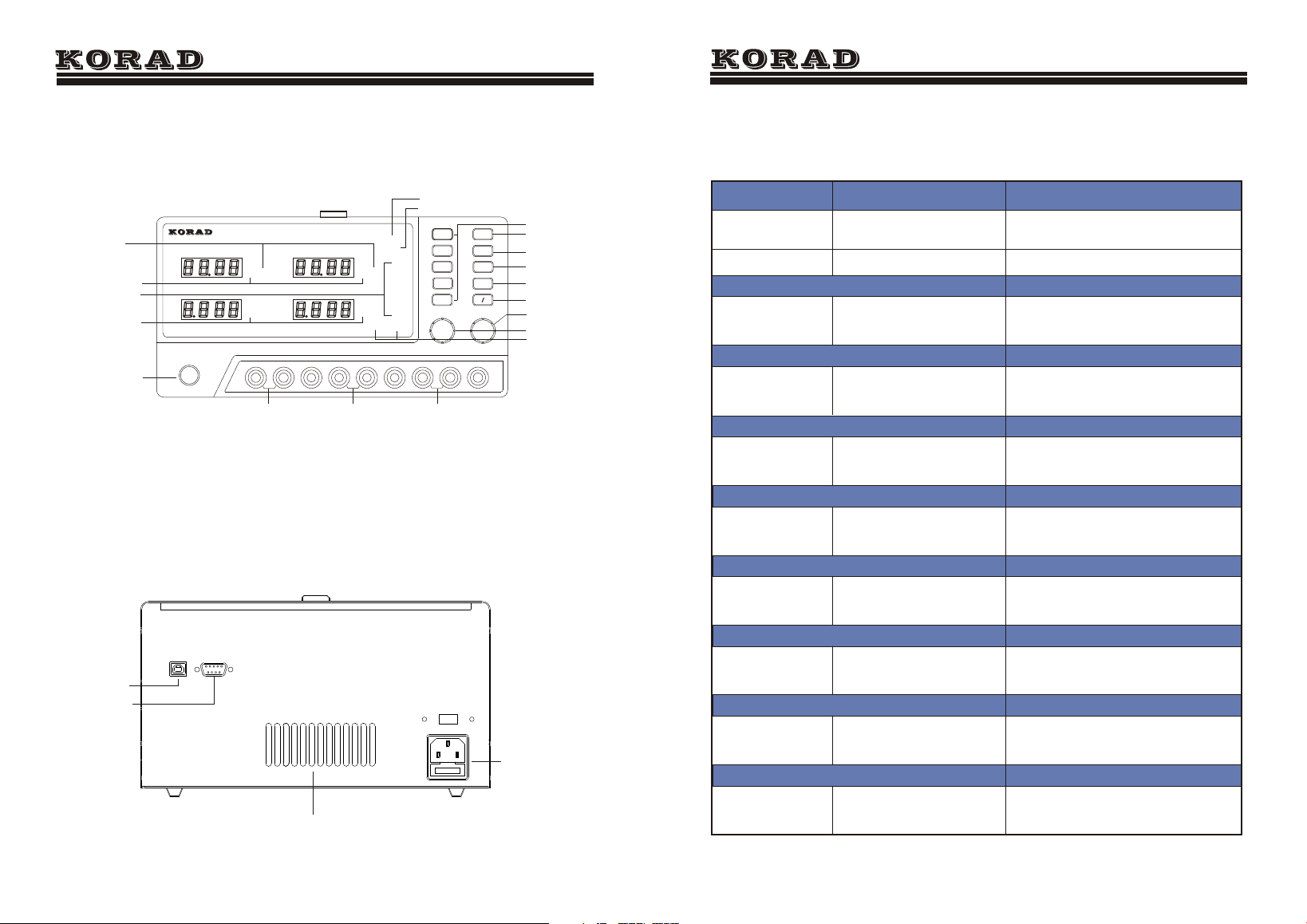
CH1 Output terminal
CH2 Output terminal
Ch3 Output terminal
Memory Indicator
Power Button
Front Panel Overview
KA3000-Series User Manual
Output Indicator
Constant Voltage
Indicator
Constant Current
Indicator
Series and Parallel
Ovet_voltage
protect on/off
Ovet_current
protect on/off
Output On/Off
Fast-recall Buttons
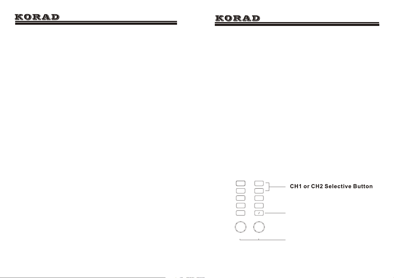
CH1Selective Button
CH2Selective Button
Current
Adjustment Knob
Current
Adjustment Knob
USB interface
Rs232 interface
Power Socket
the ventilation hole
Ovet_current SET
Ovet_voltage SET
KA3000-Series User Manual
Specifications
0- 3A
0- 5A
0- 30V
0- 30V
≤0.01% +3mv
≤0.01% +3mv
≤0.5%+20mV
≤1mVrms
≤3mArms
≤2mVrms
≤3mArms
≤150pp m
10mV
10mV
≤150ppm
≤150ppm
≤0.01%+ 5mv
≤0.01%+ 3mv
≤0.5%+ 20mV
≤150pp m
≤0.1% +5mA
≤0.1% +3mA
≤0.5% +5mA
≤150pp m
1mA
1mA
≤150ppm
≤150ppm
≤0.1%+ 10mA
≤0.1%+ 3mA
≤0.5%+ 10mA
≤150pp m
10mV
10mV
1mA
1mA
Models
KA3303 KA3305
Note: The speci below are tested under the conditions of
temperature 25℃+-5℃ and the warm-up for 20 minutes.
Load Regulation
Line Regulation
Setup Resolution
Setup Accuracy(25℃+-5℃)
Ripple(20-20M)
Temp. Coefficient
Read Back Accuracy
Read Back Temp. Coefficient
Current Range
Voltage Range
Voltage
Current
Voltage
Current
Voltage
Current
Voltage
Current
Voltage
Current
Voltage
Current
Voltage
Current
Voltage
Current
fications
13
5
Function Introduction
1. The Operation and Outputs of Voltage and Current
1. Press the button CH1 and then the CH1 display
indicator blinks; press CH1 again and then some voltage
digit on the channel 1 blinks. At this time, the voltage value
can be set by adjusting the voltage adjustment knob. Then
press the button CH1 again while the voltage digit is
blinking to switch into the current digit blinking, when the
current value can be set by adjusting the current adjustment
knob. Furthmore, when the voltage or current digit blinks,
press the voltage or current adjustment knob and the
blinking digit (i.e. the adjusting digit) can be changed.
2. After the voltage and current values are set, press the
button ON/OFF to turn on the output, when the ON indicator
on the display will be switched on; press the button ON/OFF
again to turn off the output and at this time the ON indicator
will be switched off.
KA3000-Series User Manual
M2
M5
M4
M3
M1
CH2
On Off
OVP
OCP
CH1
PUSH(V)
FIN/COARSE
PUSH(V)
FIN/COARSE
Push/Hold
LOCK/UNLOCK
Push/Hold
FIN/COARSE
SER/NIDEP
SER/NIDEP
Output On/Off
Press to set the adjusting digit
KA3000-Series User Manual
13.TRACK<NR1>
Description:Sets the output of the power
supply working on indepent or tracking
mode. NR1: 0= INDEP, 1= SER, 2= PARA
Example :TRACK1
12
6
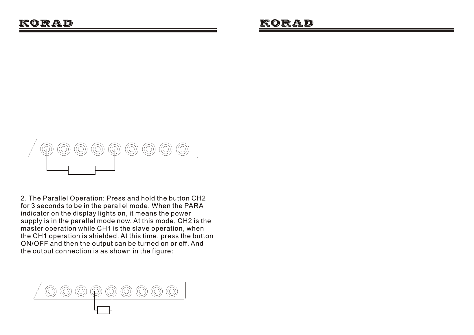
2. The Series and Parallel Operation
1. The Series Operation: Press and hold the button CH1 for
3 seconds to be in the series mode. When the SER
indicator on the display lights on, it means the power
supply is in the series mode now. At this mode, CH2 is the
master operation while CH1 is the slave operation, when
the CH1 operation is shielded. At this time, press the button
ON/OFF and then the output can be turned on or off. And
the output connection is as shown in the figure:
KA3000-Series User Manual
CH1 0-30V
GND
GND
GND
CH1 0-30V
CH1 5V3A
-
-
+
+
+
-
CH1 0-30V
GND
GND
GND
CH1 0-30V
CH1 5V3A
-
-
+
+
+
-
R
R
7. OUT<Boolean>
Description:Turns on or off the output.
Boolean:0 OFF,1 ON
Example: OUT1 Turns on the output
8. STATUS?
Description:Returns the POWER SUPPLY status.
Contents 8 bits in the following format
Bit Item Description
0 CH1 0=CC mode, 1=CV mode
1 CH2 0=CC mode, 1=CV mode
2,3,4,5 N/A
6 Output 0=Off, 1=On
7 N/AN/A
9. *IDN?
Description:Returns the KA3305P identification.
Example *IDN?
Contents KORAD KA3305P V2.0 (Manufacturer, model
name,).
10. RCL<NR1>
Description:Recalls a panel setting.
NR1 1 5: Memory number 1 to 5
Example RCL1 Recalls the panel setting stored in
memory number 1
11. SAV<NR1>
Description:Stores the panel setting.
NR1 1 5: Memory number 1 to 5
Example : SAV1 Stores the panel setting in memory
number 1
12. OCP<NR1>
Description:Over current
Example :OCP1 OCP OPEN
KA3000-Series User Manual
11

KA3000-Series User Manual
3. Recall to output
In any state, just press the buttons M1- M5 and then the
according memories can be recalled.
4. The Operation of Overcurrent Protection
7
Press and hold the button “OCP” for 3 seconds
to enter the mode of OCP setting, when the
indicator “OCP SET” lights on. And the current
values on both CH1 and CH2 display the OCP
values accordingly. By adjusting the current knob,
the OCP value can be changed. Press and hold the
button “OCP” again for 3 seconds to exit.
Furthermore, press the button “OCP” to switch
on the Overcurrent Protection (OCP) mode and the
indicator “OCP” is turned on; press the button “
OCP” again to shut down the OCP mode and the
indicator “OCP” will be turned off. When the OCP
mode is on, if the current value on the load or the
setting current is more than that in the OCP SET,
the output will be cut off.
KA3000 Series Remote Control Syntax V2.0
Command format :VSET<X>:<NR2>
1. VSET: command header
2. X: output channel
3. : separator
4. NR2: parameter
Command Details:
1. ISET<X>:<NR2>
Description: Sets the output current.
Example:ISET1:2.225
Response time 50ms
Sets the CH1 output current to 2.225A
2. ISET<X>?
Description: Returns the output current setting.
Example: ISET1?
Returns the CH1 output current setting.
3. VSET<X>:<NR2>
Description:Sets the output voltage.
Example VSET1:20.50
Sets the CH1 voltage to 20.50V
4. VSET<X>?
Description:Returns the output voltage setting.
Example VSET1?
Returns the CH1 voltage setting
5. IOUT<X>?
Description:Returns the actual output current.
Example IOUT1?
Returns the CH1 output current
6. VOUT<X>?
Description:Returns the actual output voltage.
Example VOUT1?
KA3000-Series User Manual
10
KA3000-Series User Manual
8
5.The Overvoltage Protection (OVP) Setting and Switching on
Press and hold the button “OVP” for 3 seconds to
enter the mode of OVP setting, when the indicator
“OVP SET” lights on. And the voltage values on both
CH1 and CH2 display the OVP values accordingly. By
adjusting the voltage knob, the OVP value can be
changed. Press and hold the button “OVP” again for
3 seconds to exit. Furthermore, press the button
“OVP” to switch on the Overvoltage Protection
(OVP) mode and the indicator “OVP” is turned on;
press the button “OVP” again to shut down the OVP
mode and the indicator “OVP” will be turned off.
When the OVP mode is on, if the voltage value on the
load or the setting voltage is more than that in the
OVP SET, the output will be cut off.
6. Keyboard Lock
Press and hold the voltage adjustment knob for 3 seconds,
and then the front panel will be locked; press and hold it
again for 3 seconds, and then it will be unlocked.
7. Beep ON/OFF
Press and hold the current adjustment knob for 3 seconds,
and then the beep will be turned off. Press and hold it again
for 3 seconds, it will be turned on.
COM setting Set up the COM port inside the PC according to the
following list.
• Baud rate: 9600
• Parity bit: None
• Data bit: 8
• Stop bit: 1
• Data flow control: None
Run this query command via the terminal
application such as MTTTY (Multi-threaded TTY).
*DIN?
This should return the identification information:
Manufacturer, model name, software version.
KORAD KA3305P Vx.xx
Functionality
check
KA3305P DC POWER SUPPLY
PC
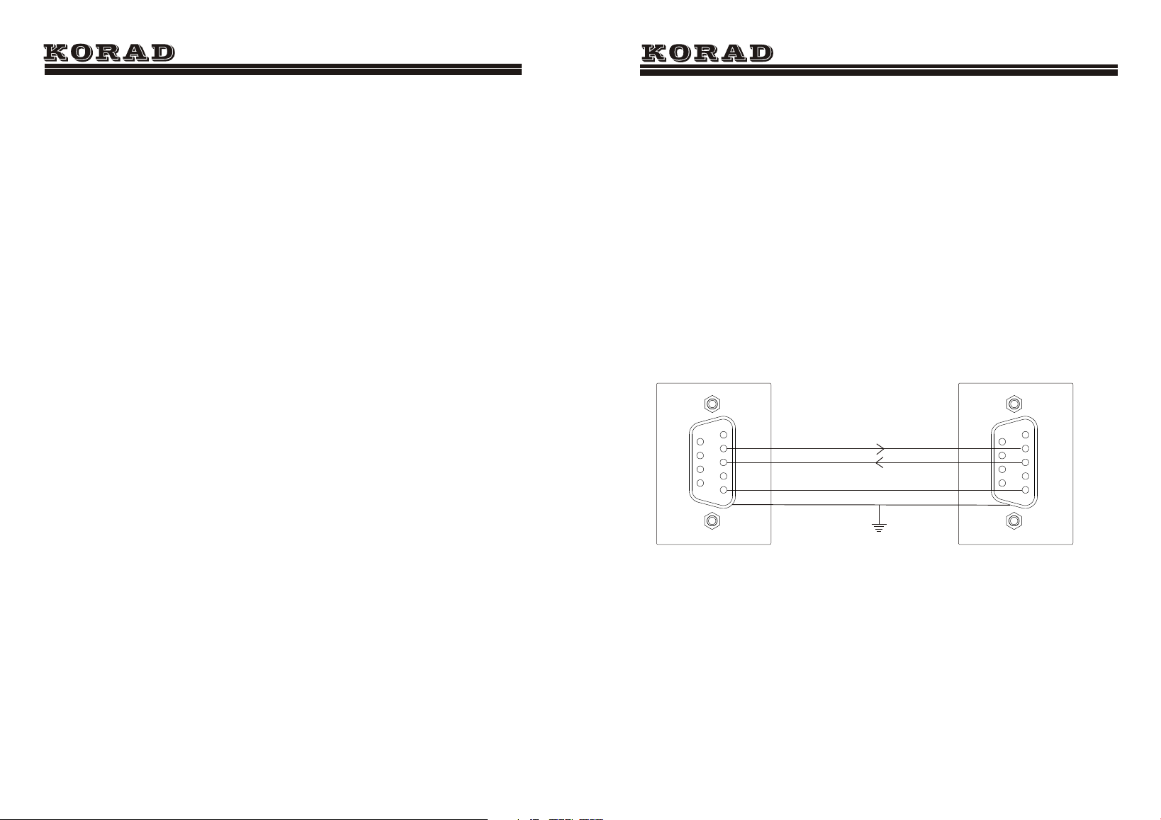
2
3
5
2
3
5
The Definition of Interface Rs232
KA3000-Series User Manual
9