
WELDING HELMET AUTO DARKENING
SHADE 11
MODEL NO: S01000.V2
Thank you for purchasing a Sealey product. Manufactured to a high standard, this product will, if used according to these instructions,
and properly maintained, give you years of trouble free performance.
IMPORTANT: PLEASE READ THESE INSTRUCTIONS CAREFULLY. NOTE THE SAFE OPERATIONAL REQUIREMENTS, WARNINGS & CAUTIONS. USE
THE PRODUCT CORRECTLY AND WITH CARE FOR THE PURPOSE FOR WHICH IT IS INTENDED. FAILURE TO DO SO MAY CAUSE DAMAGE AND/OR
PERSONAL INJURY AND WILL INVALIDATE THE WARRANTY. KEEP THESE INSTRUCTIONS SAFE FOR FUTURE USE.
1. SAFETY
WARNING! This helmet is not suitable for use with laser welding or CUTTING or for overhead welding applications.
9 Ensure all workshop safety rules, regulations and conditions are complied with when using welding equipment. The helmet will not offer
protection against misuse of workshop tools, equipment, or accessories.
9 Maintain the helmet in good condition and protect cartridge from liquid and dirt contact. Regularly replace the protective lens and
replace any damaged or worn parts. Use genuine parts only. Unauthorised parts may be dangerous and will invalidate the warranty.
9 Ensure the front cover window is securely in place before use.
9 Fit the helmet and adjust the head band so the helmet will sit as low and near to your face as possible,
9 Use helmet only in temperatures ranging from -10°C to 60°C.
9 Remove ill fitting clothing, remove ties, watches, rings and other loose jewellery.
9 Maintain correct balance and footing.
9 Ensure the floor is clear from obstructions, not slippery and wear non-slip shoes.
9 Keep children and unauthorised persons away from the working area.
WARNING! The helmet will only protect the eyes and face from radiation and sparks. It will not protect against explosive devices or
corrosive liquids.
8 DO NOT use helmet for any purpose for which it is not designed.
8 DO NOT use helmet unless you have been instructed in its use by a qualified person.
8 DO NOT open or tamper with the shade cartridge.
8 DO NOT get the helmet wet or use in damp or wet locations.
8 DO NOT leave work place with helmet in lowered position, as bright light source may darken cartridge unexpectedly.
8 DO NOT place the helmet on a hot surface.
8 DO NOT use helmet without front cover window fitted. To do so will invalidate your warranty.
9 Clean and store the helmet in a safe, dry, childproof location.
WARNING! The materials of the helmet may, when coming into contact with the wearer’s skin, cause an allergic reaction to
susceptible individuals.
WARNING! Before welding always inspect the cartridge filter to ensure that it is not damaged. To test the filter prior to welding, direct
the front of the cartridge filter to a bright light source which will cause the lens to darken. Then using your hand rapidly
cover and uncover the sensor. The filter should lighten momentarily then return to a dark state.
WARNING! DO NOT use the helmet if damaged or you suspect it may be faulty. (Contact Sealey stockist).
▲ DANGER! DO NOT USE if, at any time, the face plate in the cartridge FAILS to darken when exposed to a welding spark.
Remove cartridge and return to your Sealey stockist for checking.
9 Continued use of the product knowing that the auto darkening feature is NOT FUNCTIONING may DAMAGE YOUR
EYES and CAUSE BLINDNESS.
2. i INTRODUCTION
Shade 11 welding helmet. Complies to BS EN 379, BS EN 175 and DIN standards. Features automatic switching from light to dark on striking arc.
Fitted with adjustable sensitivity and delay controls for switching light to dark. Deluxe contoured helmet with fully adjustable headband featuring
front pad for added comfort. Suitable for MIG, TIG and arc welding.
3. i SPECIFICATION
Model no: ............................................................. S01000.V2
Grinding function ................................................................no
Operating temperature ...................................-10°C to +60°C
Operating time Light/Dark ............................................ 0.1ms
Power ....................................................... Lithium cell battery
Shade active ...................................................................... 11
Shade inactive .....................................................................3
Viewing area ........................................................ 91 x 39mm
Refer to
instruction
manual
Original Language Version
© Jack Sealey Limited
S01000.V2 Issue 4 (F) 27/03/24
4. OPERATION
WARNING! Before using the helmet for welding ensure you have read and understood the safety instructions in Section 1.
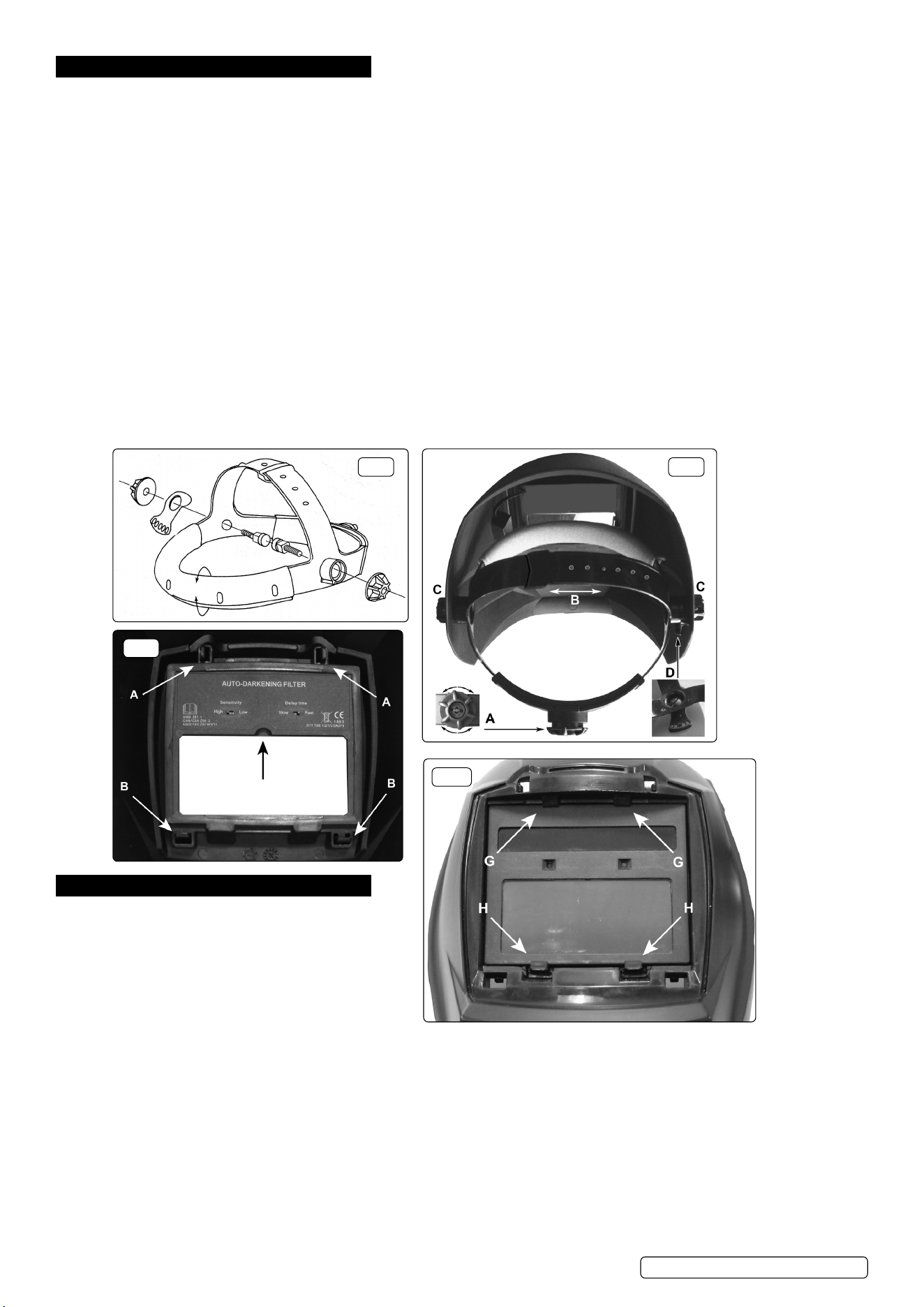
4.1. Assembletheheadbandparts(seeg.1)intothemaskasindicateding.2.Beforethemaskcanbeusedtheheadbandmustbe
adjustedtottheuserproperly.
4.2. ADJUSTING THE FIT OF THE HELMET
The overall circumference of the headband can be made larger or smaller by pushing in and rotating the knob on the back of the
headband(Seeadjustment‘A’ing.2).Thiscanbedonewhilstwearingthehelmetandallowsjusttherighttensiontobesettokeep
thehelmetrmlyontheheadwithoutitbeingtootight.
4.3. If the headband is riding too high or too low on your head adjust the strap which passes over the top of your head. To do this release
the end of the band by pushing the locking pip out of the hole in the band. Slide the two portions of the band to a greater or lesser
widthasrequiredandpushthelockingpipthroughthenearesthole(Seeadjustment‘B’ing.2).
4.4. Testthetoftheheadbandbyliftingupandclosingdownthehelmetafewtimeswhilstwearingit.Iftheheadbandmoveswhilsttilting
re-adjust it until it is stable.
4.5. ADJUSTING HELMET TILT
If the cartridge window is not aligned with the eyes when the helmet is in the lowered position adjust the tilt of the helmet in relation to
theheadband.Referringtog.2loosentheknob‘C’adjacenttothetiltplate‘D’.Liftthetiltplateoffthexedpegwithinthehelmetand
rotate it to the required position and allow one of the holes in the plate to drop back over the peg. Retighten the clamp knob ‘C’.
4.6. SELECTING DELAY TIME/RESPONSE TIME
The delay time in which it takes the lens to change from dark to light or vice versa can be set to ‘slow’ or ‘fast.’ The switch is on the
insideofthecartridge,(seeg.3.)
4.7. SENSITIVITY
Fornormalambientlightconditionssetthesensitivityknobtothehighsetting(g.3).
For conditions where there is an excess of light, which may affect the performance of the lens, move the switch to the low setting.
5. MAINTENANCE
5.1. CHANGING THE SHADE CARTRIDGE
5.1.1. All components clip into the front of the helmet as
showning.4above,(shownwithoutfrontcover.)
5.1.2. Toaccessthecartridgerstlyremovethefrontcover
by releasing the four clips accessible on the inside of
the helmet above and below the cartridge.
5.1.3. Releasethetopclipsrst(see‘A’ing.3)bypressing
them inwards and forwards. Then release the bottom
clips(see‘B’ing.3)bypressingthemdownwardsandforwards.Liftoffthefrontcover.
5.1.4. Referringtog.4,pushdownwardsonthetwoclips‘H’whilstpushingthebottomedgeofthecartridgeoutwardsfrominsidethe
helmet. When it is free from the lower clips pull the cartridge downwards and forwards to free it from the upper retainers. (See ‘G’ in
g.4.)
5.2. FITTING THE NEW CARTRIDGE
(Part No: S01000.03)
5.2.1. Takethenewshadecartridgeandhookthetopedgeundertheupperretainers‘G’.Pushrmlyonthebottomedgeofthecartridgeso
thatitsnapsintoplacebehindthetwoclips‘H’.
5.2.2. Placethefrontcover‘A’ontothefrontofthehelmetsothatthecoverclipspassintothematchingholesinthehelmet.Pressrmlyon
thetopofthecovertoengagethetopclipsthenpressrmlyatthebaseofthecovertoengagethelowerclips.
5.3 REPLACING THE OUTER PROTECTIVE COVER LENS
(Part No:S01000.01)
Remove the front cover as described in sections 5.1.1 and 5.1.2.
fig.1 fig.2
fig.3
fig.4
Original Language Version
© Jack Sealey Limited
S01000.V2 Issue 4 (F) 27/03/24
5.2.3. Remove the lens from the back of the front cover by lifting one vertical edge and sliding the whole lens sideways until it releases from
itsretainingpoints.Thelenswillexsufcientlytoallowyoutodothis.
5.2.4. Flex the new lens and slide it in from one side under the retaining points until it is in position. Ensure that it laps over the inside of the
lens opening on either side.
5.3. REPLACING THE CARTRIDGE PROTECTIVE LENS
(Part No: S01000.02)
5.3.1. The protective cartridge lens that can be seen on the inside of the helmet should be replaced if damaged. The lens is held in place at
its four corners.
5.3.2. Toremovethelensplaceyourngertipintothescoopjustbelowthecartridgecontrols(seeg.3)andexthelensupwardsuntilthe
upper corners release. Lift out the lens.
5.3.3. Take the new lens and place one vertical edge under the corner retainers in the lens recess. Flex the lens in the middle and tuck the
other end into the corner retainers.
5.4. CLEANING
5.4.1. Clean helmet by wiping with a soft cloth. Clean cartridge surfaces regularly. DO NOT use solvent based cleaners. Clean sensors and
solar cells with methylated spirit using a clean cloth and wipe dry with a lint-free cloth.
6. TROUBLESHOOTING
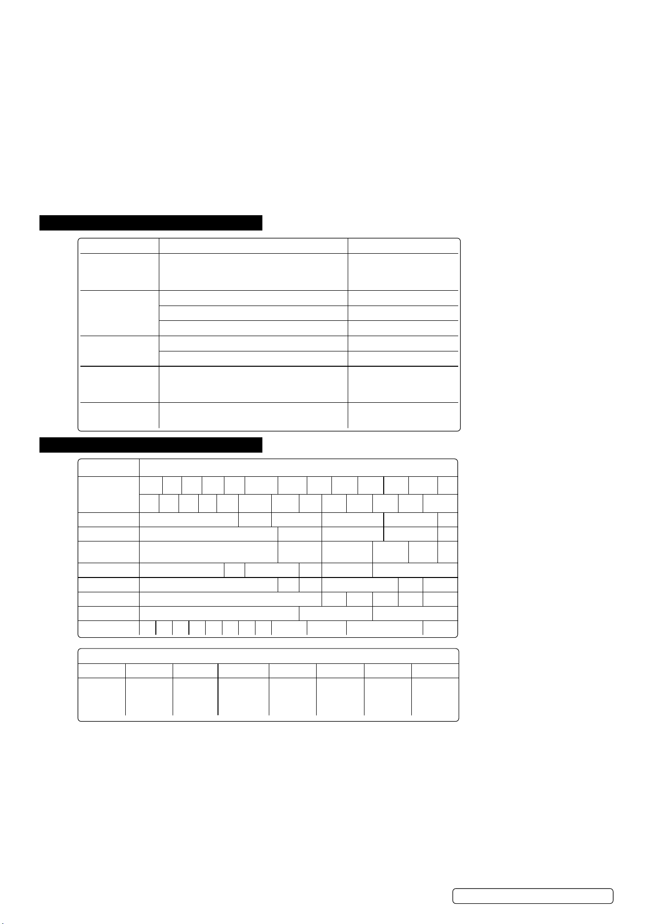
7. SHADE GUIDE TABLES
Problem Cause Solution
Irregular darkening
or dimming.
The headband may have been unevenly set on
the two sides of the helmet (unequal distances
from the eyes to the shade cartridge).
Readjust the distance of
the shade cartridge.
Shade cartridge
does not darken or
ickers.
The sensors are soiled or obstructed. Clean.
Front cover lens oiled or damaged. Clean or replace.
Welding current too low. Adjust weld amps.
Poor vision. Operative lenses and/or shade cartridge soiled. Check, clean or replace.
Insufcientbackgroundlighting. Adjust light.
Slow response. Operating temperature too low.
DO NOT use at
temperatures below -10
o
C
(14
o
F).
Welding helmet
slips. Headbandadjustmentsincorrect. Refer to section 4.
CURRENT (AMPERES)
WELDING
PROCESS
0.5 2.5 10 20 40 60 125 175 225 275 350 450
1.0 5.0 15 30 50 100 150 200 250 300 400 500
Covered Electrode Shade 9 S10 Shade 11 Shade 12 Shade 13 S14
MIG Plate Welding Shade 10 Shade 11 Shade 12 Shade 13 S14
MIG Sheet
Welding
Shade 10 Shade 11 Shade 12 S13 S14 S15
TIG Shade 9 S10 Shade 11 S12 Shade 13 Shade 14
MAG Shade 10 S11 S12 Shade 13 S14 S15
Arc Gouging Shade 10 S11 S12 S13 S14 S15
Plasma Cutting Shade 11 Shade 12 Shade 13
Plasma Welding 4 5 6 7 8 9 10 11 S12 Shade 13 Shade 14 S15
Meaning of the markings on the filter:
4 9 13 SEALEY 1 3 1 379
Light state
scale no.
Lightest dark
state scale
no.
Darkest
state scale
no.
Manufacturers
identification.
Optical class. Diffusion of
light class.
Variation in
luminence
transmittance
class.
Number of
the applied
standard.
Original Language Version
© Jack Sealey Limited
S01000.V2 Issue 4 (F) 27/03/24

Original Language Version
© Jack Sealey Limited
S01000.V2 Issue 4 (F) 27/03/24
This document has been drawn up according to Regulation (EU) 2016/425 as amended to apply to GB for Personal Protective
Equipment. The declaration of conformity can be accessed at www.sealey.co.uk.
Note: It is our policy to continually improve products and as such we reserve the right to alter data, specifications and component parts without prior
notice. Please note that other versions of this product are available. If you require documentation for alternative versions, please email or call
our technical team on technical@sealey.co.uk or 01284 757505.
Important: No Liability is accepted for incorrect use of this product.
Warranty: Guarantee is 12 months from purchase date, proof of which is required for any claim.
ENVIRONMENT PROTECTION
Recycle unwanted materials instead of disposing of them as waste. All tools, accessories and packaging should be
sorted, taken to a recycling centre and disposed of in a manner which is compatible with the environment. When
theproductbecomescompletelyunserviceableandrequiresdisposal,drainanyuids(ifapplicable)intoapproved
containersanddisposeoftheproductanduidsaccordingtolocalregulations.
REGISTER YOUR
PURCHASE HERE
EU | Sealey EU Ltd, Farney Street, Carrickmacross, Co. Monaghan, A81 PK68 Ireland
UK | Sealey Group, Kempson Way, Suffolk Business Park, Bury St Edmunds, Suffolk. IP32 7AR
01284 757500 sales@sealey.co.uk www.sealey.co.uk